Embed Size (px)
Citation preview

Vision of Building Simulation
Michael WetterSimulation Research Group
January 26, 2013
1
Informatics

2
We believe that simulation tools should not constrain the user in what systems can be analyzed and optimized.
Our approach is rooted in a separation of data, model, and solvers.This allows using state-of-the-art technologies whose development required skills typically not found in the buildings community.
It turns out that that this leads to natural model formulations that allow modeling controls, transferring BIM to simulation, deploying code to hardware, ...

Needs
3
Schematically define any
building,
HVAC & control system
to be
simulated, optimized, analyzed and operated

Schematically define any
building,
HVAC & control system
to be
simulated, optimized, analyzed and operated
Needs
4
BIMSchematiceditor User-extensible
component & system library, in exchangeable standard format
simulationcode
optimizationcode
integration with code compliance, visualization, ...
code generation for HIL and building control systems
Modern symbolic & numerical routines for hybrid, stiff, sparse systems of differential algebraic equations
Special-purpose GUI
PDE and ray-tracing parallel code
Manufacturer catalog

Separation of concern
5
Solves the equationsModeling Computation
C*der(T) = Q_flow;0 = T - TBoundary;
a:=2;b:=2*a;
Graphical modeling - input/output free - block-diagram - state machines - bond-graphs
Acausal equations
Algorithmic code
Code for time-domain simulation
Code for optimization
Code for real-time operation
Limited memory and storage.Constraints on computing time.
Differentiation for gradient.Symbolic processing for collocation.
Code for co-simulation as FMU
Provide API for model discovery andthat returns xk+1=f(xk, tk)
Code for model exchange as FMU
Provide API for model discovery and that expose right-hand-side of dx(t)/dt=f(x(t),t)
Related efforts within the building simulation community include ENET (Low and Sowell, 1982), SPANK (Sowell et al., 1986), SPARK (Buhl et al., 1993) and the Neutral Model Format NMF (Sahlin and Powell, 1989).
external "C"y=someCFunction(x);
C interface
Specifies the system
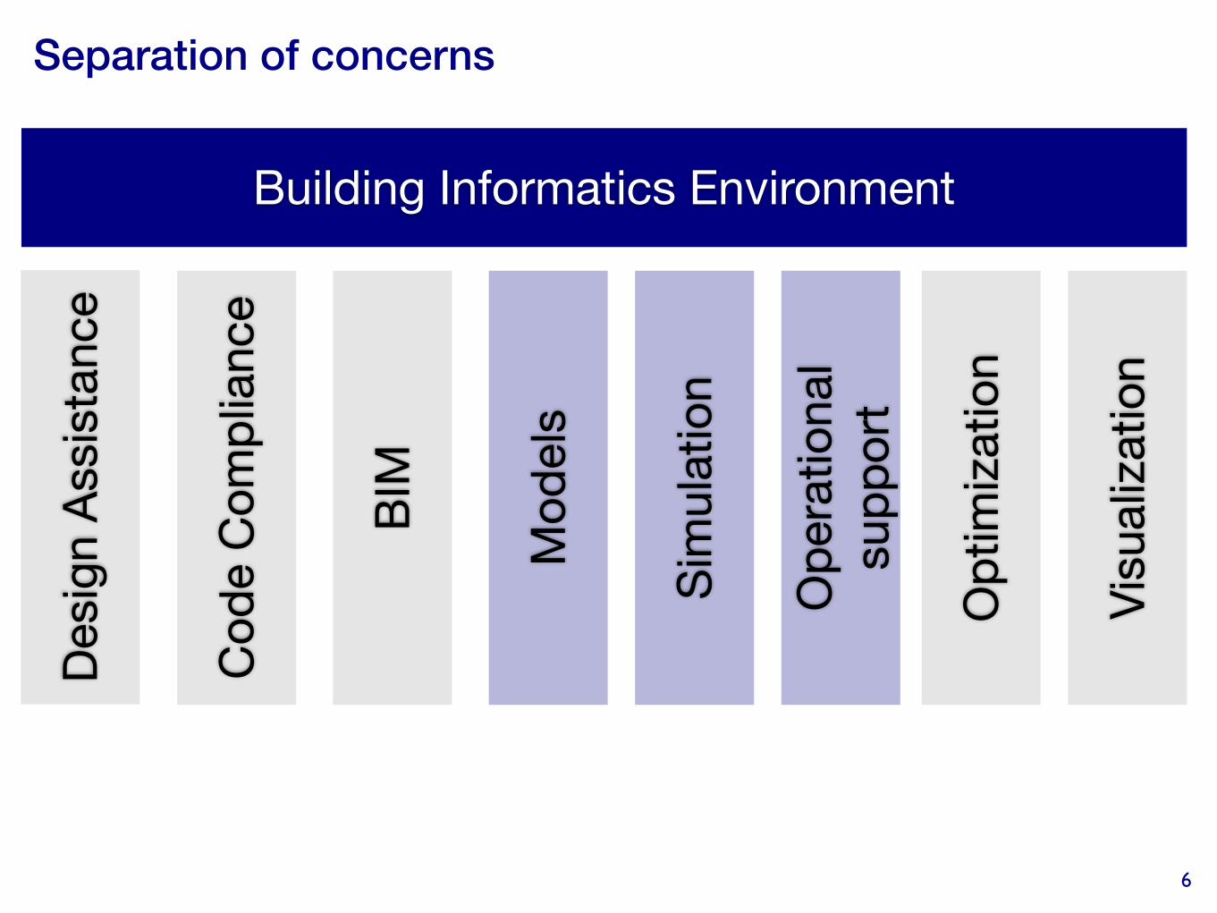
Separation of concerns
6
Building Informatics Environment
Desi
gn A
ssis
tanc
e
Cod
e C
ompl
ianc
e
BIM
Mod
els
Sim
ulat
ion
Ope
ratio
nal
supp
ort
Opt
imiza
tion
Visu
aliza
tion

Opportunities
7
Domain-specific libraries
Modeling language &
tool API
Advanced solvers GUIs
MathBuildingscience
Controls Computerscience
Collaborate ....and integrate

Adopting open standards allows reusing technologies that can be shared across industries
8
Functional Mockup Interface
ITEA project, 30 partners, > 175 person years, > 28 Mill. € budget, July 2008 - June 2011.
First version published in 2010. Supported by 38 tools.
Modelica
Open modeling language, started in 1996.
Free Modelica Standard Library: 2190 models and functions.

Modularization and encapsulation leads to transparency
9
connector HeatPort_a "Thermal port for 1-dim. heat transfer" Modelica.SIunits.Temperature T "Port temperature"; flow Modelica.SIunits.HeatFlowRate Q_flow "Heat flow rate (positive if flowing from outside into the component)";end HeatPort_a;
model HeatCapacitor "Lumped thermal element storing heat"
parameter Modelica.SIunits.HeatCapacity C "Heat capacity"; Modelica.SIunits.Temperature T "Temperature of element"; Interfaces.HeatPort_a port "Connector for (T, Q_flow)";
equation T = port.T; C*der(T) = port.Q_flow;end HeatCapacitor;
a.port.T = b.port.T0 = a.port.Q_flow + b.port.Q_flow
a b
connect(a.port, b.port);

Acausal models allow graphical coupling of controls, algebraic equations, differential equations and state machines in schematic editor
10
ordinary differential equation
algebraic equation
state graph
algorithmic code for controls
state events
spatially discretized PDE
acausal schematic diagram (w. flow reversal)
block-diagram

Acausal models map directly to physical systems.
11

Models can be encapsulated and exported for real-time applications
12
FMU C
Models of process & controls
(Rapid prototyping, design of experiments,analysis)
Exchange formats
Real-time applications
(Control and monitoring, e.g., MPC algorithms, as part of energy information systems)

LBNL distributes free open-source Modelica “Buildings” library with 300+ models and functions
Air-based HVAC systems. Hydronic heating systems. Chiller plants.
Natural ventilation, multizone air exchange, contaminant transport.
Room heat transfer,incl. window (TARCOG).
Renewables (2013).Embedded Python (2013).District energy systems (2013/2014).
13http://simulationresearch.lbl.gov/modelica

The “Buildings” library has been used across a wide range of applicationsControl development& verification
14
Workforce training throughLearnHPB emulator
FDD
Standards development Hardware-in-the-loop Rapid prototypingRoom$
absorbed,$$incident$solar$irradia1on$
Virtual$test$cell$(Modelica)$
Report$on$actual$state$of$room$&$
blind$
For$each$Blind$posi1on$
Measured$data$
ti+1 = ti +Δt
Control$signals$
Save$state$$variables$
Hea1ng$and$$cooling$loads$
Boundary$$condi1ons$
Physical$test$cell$
Find$op1mal$blind$
posi1on$
RayDtracing$(Radiance)$
Synchronize$1me$

Building Controls Virtual Test Bed allows run-time data exchange among simulators and control systems
HVAC & controlsModelica
wireless networksPtolemy II
lightingRadiance
building energyEnergyPlus
Building Controls Virtual Test Bed http://simulationresearch.lbl.gov/bcvtbFree open-source middle-ware based on UC Berkeley’s Ptolemy II program.
real-time datawww+xml
controlsSimulink controls & data analysis
MATLAB
building energyTRNSYS
implementedin next release
building automationBACnet
building energyESP-r
BCVTB
hardware in the loopA/D
co-simulationFMU
15

The Functional Mockup Interface allows export and import of simulators for co-simulation and hardware-in-the-loop
16
EnergyPlus
Modelica
MATLAB/SimulinkBCVTB
National InstrumentsVeriStand
(Incomplete list of tools, see https://www.fmi-standard.org/tools for 38 tools that support FMU).

The Functional Mockup Interface allows export and import of simulators for co-simulation and hardware-in-the-loop
17
Rapid virtual prototyping.Path towards embedded computing.
Whole building energy analysis.Reuse of 500,000 lines of code.

WUFIPlus links to Modelica models of heating systems through the Functional Mockup Unit
18
varying variables must be declared as input within the Modelica code. Their causality must be set to Input. If parameters appear in if-statements in sub-models, the model must be re-compiled for a change of their value. In the exported and compiled FMU such a parameter is automatically set to constant and the value is firmly anchored. Changing the value of constants within the FMU is not possible. If-statements are often responsible for discontinuities and events. They should be avoided during the mod-el design process because they increase the computa-tion time [7]. However, to set a parameter of an if-statement in the compiled FMU, a workaround is to define the parameter as input. There are more than one HVAC configurations with different devices and different parameters and, con-sequently, many FMUs. WUFI®Plus has to interact with the HVAC system configuration, which is cho-sen by the user of the software. A FMU adapter (Figure 2) is written in the object-oriented language C++ to manage dynamic FMU instantiation, initiali-zation, set inputs, obtain outputs and execute time steps. Therefore, the adapter receives information about the different kinds of configurations and their parameters (their value references).
Figure 2: Communication between building model and heating systems As mentioned, the building model and the HVAC models have to interact with each other. Some results of one are needed as input for the other. Two differ-ent insertion algorithms were investigated and are discussed below.
3.1 Iterative approach
As described before, WUFI®Plus uses an iterative process to simulate the interior temperature and moisture for defined zones. Also airflow is calculat-ed iteratively. For short computation times there is a solver designed for fast convergence of these values with only a few iterations. Indeed, the HVAC sys-tems influence the indoor climate. The first approach was to use the existing heat and moisture balance
algorithm. The HVAC system receives, for example, the indoor set point temperature and the actual tem-perature of a zone and a time step and delivers the possible heat flow to the zone. If the heat balance is not satisfied, the current temperature will be in- or decreased and the HVAC system must iterate (Figure 3).
Figure 3: Flow chart - iterative approach The advantage of this approach is to use the estab-lished flexible balance system. The HVAC model can be coupled in a fast way with only a few modifi-cations of the WUFI®Plus algorithm. However, this method requires repeating and discarding of FMU time steps. Therefore the parameter newStep of fmiDoStep(..) can be set to fmiFalse if the capa-bility flag canRejectSteps of the FMU is true. Until now this feature is not supported by the exported FMU. This is specific to Dymola and might not be the case for other simulation environments. Howev-er, in the analyzed case the missing feature is a prob-lem for the implementation of the iterative approach. If a time step is regarded as an entire simulation, a workaround could be to re-initialize the FMU for every time and iteration step. In order to retain all information, all time varying variables must be stored after a step and re-stored as initialization val-ues for the next step. To repeat a step, the values of the last step are used. This could be time and memory consuming. Furthermore, some states of the model, which cannot be stored in the cache, may change during a time step. A further issue of this coupling approach is that the iteration might end in a continuous loop. The heat supply system models are designed to deliver a heat
Matthias Pazold, Sebastian Burhenne, Jan Radon, Sebastian Herkel …
DOI Proceedings of the 9th International Modelica Conference 951 10.3384/ecp12076949 September 3-5, 2012, Munich, Germany
Source: Pazold et al., 2012, http://dx.doi.org/10.3384/ecp12076949

19
Annex 60
New generation computational tools for building and community energy systems
based on the Modelica and Functional Mockup Interface standards
Duration: 2012-2017
Operating agents: Michael Wetter (LBNL) and Christoph van Treeck (RWTH Aachen, Germany).
Participation:30 institutes from
Austria, Belgium, China, France, Germany, Ireland, the Netherlands, Sweden and the USA,
and possibly Switzerland.

Annex 60
20
Building and community energy gridsDesigned & operated as integrated, robust, performance-based system.
Energy and control systems modeling libraryModelica.Free and open-source.Standardized interfaces.Buildings, districts, controls.
Co-simulation & model-exchange tools and interfacesFunctional Mockup Interface standard.FMI interfaces in existing simulators.Co-simulation algorithms.
BIM translators
Standardized model data exchange.Modelica/BIM interfaces.
Multiple scales
Multiple disciplines
Multiple domains
Multiple tools
International Energy Agency
Energy Conservation in Buildings and Community Systems Programme - ECBCS
Energy Conservation in Buildings and Community Systems Programme (ECBCS)
An Introduction
International Energy Agency
Standardized language, APIs and data models
Applications on building design, district design, model-use during operationDissemination

In summary, modeling gets closer to the physical and logical systems: Declare model and generate code
• Increased level of abstraction.
• Models are expressed in a modeling language, not as simulation code.
• Inter-disciplinary collaboration.
• These points allow modeling of phenomena and new use cases that are outside the capabilities of today’s building simulation programs.
Links
• www.modelica.org
• www.fmi-standard.org
• simulationresearch.lbl.gov
21