Embed Size (px)
Citation preview
FACTA UNIVERSITATIS Series: Working and Living Environmental Protection Vol. 5, No 1, 2008, pp. 59 - 72
INFLUENCE OF ULTRASONIC TRANSDUCER ACOUSTIC IMPEDANCES AND DIMENSIONS ON
ITS INPUT ELECTRICAL IMPEDANCE
UDC 534.6:550.837
Dragan Mančić, Milan Radmanović, Zoran Petrušić, Goran Stančić
Faculty of Electronic Engineering, University of Niš, Serbia e-mail: [email protected]; [email protected];
[email protected]; [email protected]
Abstract. In this paper the influence of the loads on all contour surfaces of an ultrasonic sandwich transducer on its input electrical impedance is considered. Additionally, input electrical impedance is analyzed as a function of all the dimensions of the sandwich transducer constitutive parts. The three-dimensional matrix model of ultrasonic sandwich transducers, recently proposed by the authors, has been used. In the analysis of the complete power ultrasonic sandwich transducers, these influences are for the first time considered in the presented way.
Key Words: Ultrasonic transducer, Electrical impedance, Acoustic impedance
1. INTRODUCTION
Langevin's ultrasonic sandwich transducers, widely used in ultrasonic cleaning and welding systems, are complex and composite structures composed of piezoelectric ce-ramic elements and metal rings and discs, pre-stressed by a metal bolt. Modeling of the ultrasonic sandwich transducers is a complex problem, from both a mechanical and elec-trical point of view [1]. Modeling of the transducer has been significantly advanced with the introduction of adequate models of component (constituent) parts. New and better models of piezoelectric ceramic rings (made of PZT ceramic) as well as models of trans-ducer metal component parts (a duraluminium emitter, reflector and a bolt made of steel) contribute to a more precise prediction of the transducer behaviour.
Three-dimensional matrix models of piezoelectric ceramic (piezoceramic) rings and metal discs, previously realized by the authors [2,3], enabled obtaining adequate models of symmetric and asymmetric ultrasonic sandwich transducers, used in many powerful ultrasound applications [4,5].
Received November 7, 2008
D. MANČIĆ, M. RADMANOVIĆ, Z. PETRUŠIĆ, G. STANČIĆ 60
By applying the three-dimensional matrix model of pre-stressed asymmetric ultrasonic sandwich transducer [5], its electric input impedance dependence on acoustic load at all contour surfaces is analyzed in this paper. In addition, input electric impedance is ana-lyzed as a function of the dimension of all the component parts of a sandwich transducer. These dependences are for the first time considered in such a way in the analysis of the complete power ultrasonic sandwich transducer.
2. THREE-DIMENSIONAL MODEL OF TRANSDUCERS
The model of an asymmetric transducer, already described by the authors [5], is pre-sented in Figure 1a, while Figure 1b represents the shape of the most frequently used asymmetric ultrasonic transducer, with the corresponding parts marked the same way as in Figure 1a. The model of the ultrasonic sandwich transducer is obtained by the appropriate connecting of corresponding mechanical accesses (inputs, ports) of all the transducer component parts, taking into account the actual existing contacts of the surfaces repre-sented by these inputs.
Under the condition that the outer contour surfaces of transducer component parts are loaded by surrounding environment acoustic impedances of different values Zi that are small for the unloaded surface and vice versa, and with alternating voltage applied to the electric inputs, it is possible to determine any transfer function of interest for the given system. Of course, the most important characteristic which can be achieved by this way of modeling is the input electric impedance of the ultrasonic sandwich transducer.
3. NUMERICAL RESULTS
In order to present the possibilities of the proposed model for ultrasonic sandwich trans-ducer analysis, as in the case of the piezoceramic rings [2], it is possible to analyze changes of the input transducer impedance in the function of the frequency and specific transducer pa-rameters, that is, in the function of different dimensions of the constituent elements and different acoustic impedances that load the external surfaces. Thereat is the analysis of a concrete sand-wich transducer with 5mm thick PZT8 rings and with fundamental resonant frequency of 41.6kHz, whose dimensions, according to the symbols from Figure 1b, are the following: l1=l2=5mm, 2a1=2a2=38mm, 2b1=2b2=15mm, l3=l11=18mm, l8=l9=8mm, l5=l7=11.2mm, l4=l6=0, l10=l1+l2+l7, 2b6=2b5=2a8=12.8mm, 2a7=12.8mm, 2a3=2a4=2a5=2a6=40mm, 2b3=2b4=2b7=8mm, 2a9=2a10=2a11=8mm. Because of the mutual coupling of the oscilla-tions, it cannot be claimed for a specific resonant mode of a transducer that it originates from the radial or thickness mode of only one transducer constituent element, i.e., that it is deter-mined by only one of its dimensions. Resonant modes of the transducer depend on the coupling of several specific modes, that is, they simultaneously depend on several dimensions, but it is now obvious which dimensions of the constituent transducer parts affect the observed resonant mode the most.
Influence of Ultrasonic Transducer Acoustic Impedances and Dimensions ... 61
Fig. 1. Design and model of the asymmetrical ultrasonic sandwich transducer. Metal ending parts are made of different materials, usually duraluminium (emitter) and steel (reflector)
steel PZT ceramic
duraluminium
(b)
D. MANČIĆ, M. RADMANOVIĆ, Z. PETRUŠIĆ, G. STANČIĆ 62
3.1 Analysis of the influence of the metal emitter parameters First, in Figure 2, we have presented the dependence of the input impedance of this
transducer in the function of frequency and emitter length, if the emitter length increases by 30mm from the primary length of 18mm. The impedance characteristic of this transducer contains six main resonant modes in the observed frequency range. In all these analyses the most important factor is the behavior of the lowest resonant modes, especially the first mode, which is the operating resonant mode of the transducer. From Figure 2 it is obvious that at a small increase of the emitter length, frequency decrease of the first, and especially the sec-ond and the sixth resonant mode occurs, while frequencies of the third, fourth, and fifth mode do not depend on this change. At great emitter lengths, resonant frequencies of the second, fourth, and sixth mode do not depend on the emitter length, while the frequencies of the first, third, and fifth mode are functions of the emitter length. At great emitter lengths, between the third and the fourth mode, another resonant mode occurs. Accordingly, only the first mode is the true thickness resonant mode, because it depends on the emitter length in the entire observed range. Based on the analysis according to the proposed model, it can, therefore, be assumed that if the emitter length was increased, the fundamental resonant fre-quency would decline, but the approaching of the first and the second mode would be per-formed, which is unfavorable, as the second mode is undesirable in the vicinity of the fun-damental resonant mode. The presence of the undesirable (parasite) modes in the vicinity of the operating frequency may significantly affect the quality of ultrasonic cleaning or weld-ing. According to the form of the presented modes, if the emitter length was smaller than the initial length, the first and the second mode would also be approached, thus the adopted emitter length of 18mm is optimal, and then the distance between the first and the second resonant mode is the greatest. The second resonant mode is, accordingly, largely determined by the emitter length, yet does not depend on that dimension.
Fig. 2. Change of the input impedance of a transducer in the function of frequency and
emitter length l3+l4
Influence of Ultrasonic Transducer Acoustic Impedances and Dimensions ... 63
There is an inverse situation in the case of change of the emitter cross-section, and that case is presented in Figure 3, which shows the input impedance change in the function of frequency and outer diameter of the emitter, which changes in the range from 14mm to 40mm. In that case, the resonant frequencies of the second, fourth, and sixth mode de-crease with the increase of the outer emitter diameter, while the frequencies of the first, third, and fifth mode do not change under the effect of this change. The thickness mode does not depend on this change almost at all, which was expected, and on the other hand, the behavior of the fourth and the sixth mode shows that these modes depend mostly on the radial dimensions of the emitter. By decreasing the outer diameter of the emitter, the first and the second resonant mode are separated, which is desirable from the excitation aspect, but thereby the cross-section of the emitter in relation to the ceramic is decreased, which limits the transducer possibilities.
Fig. 3. Change of the input impedance of a transducer in function of the frequency and outer diameter of the emitter 2a3=2a4
A similar analysis may be performed in the case of the observed transducer with con-stant dimensions, with an emitter of 18mm, if different acoustic loads are connected to the operating emitter end and to the external cylindrical emitter surface. The characteristics of the input transducer impedance in that case are presented in Figures 4 and 5.
D. MANČIĆ, M. RADMANOVIĆ, Z. PETRUŠIĆ, G. STANČIĆ 64
Fig. 4. Change of the input impedance of a transducer in function of the frequency and
acoustic load Z4b on the plane surface of the emitter
Fig. 5. Change of the input impedance of a transducer in the function of frequency and
acoustic load Z3=Z4a on the external cylindrical emitter surface
Influence of Ultrasonic Transducer Acoustic Impedances and Dimensions ... 65
Based on the application of the proposed model, it is obvious that the second undesirable resonant mode will decrease during emitter loading in operating conditions (Figure 4), and it will not affect the fundamental resonant mode, so this too is a confirmation of the proper transducer design. This dependence on acoustic load on the operating surface also shows that the first, second, and sixth modes depend on the emitter characteristics in the thick-ness direction. In Figure 2, the second and the third resonant mode are at a mutually suffi-cient distance at great emitter lengths, while they are close at small emitter lengths. The dependence presented in Figure 4 also confirms the strong mutual coupling of these modes, for the initial emitter length of 18mm, because at high loading of the emitter, the second mode disappears and approaches the third resonant mode, where it affects its form. According to Figure 5, the high mechanical load on the cylindrical surface of the emitter shows that the greatest change is in the fourth resonant mode, while there is a sig-nificant change in the second and the sixth resonant mode, which is analogous to the con-clusions obtained based on Figure 3.
3.2 Analysis of influence of the metal reflector parameters
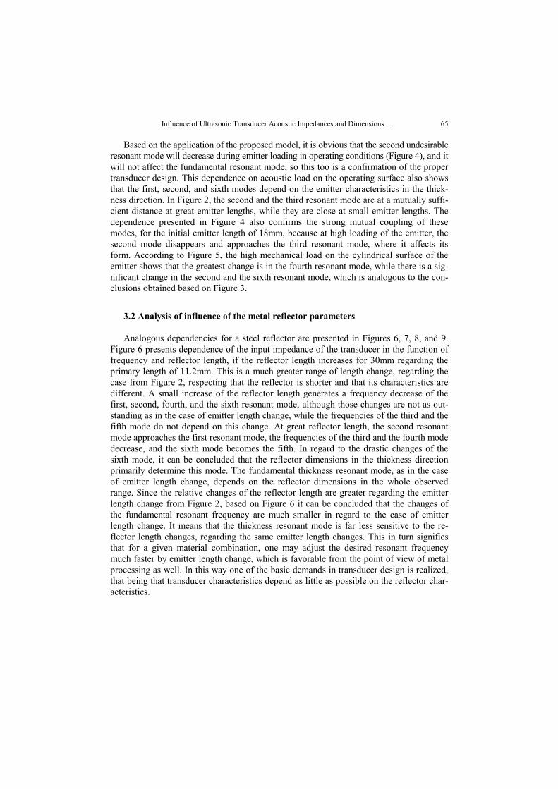
Analogous dependencies for a steel reflector are presented in Figures 6, 7, 8, and 9. Figure 6 presents dependence of the input impedance of the transducer in the function of frequency and reflector length, if the reflector length increases for 30mm regarding the primary length of 11.2mm. This is a much greater range of length change, regarding the case from Figure 2, respecting that the reflector is shorter and that its characteristics are different. A small increase of the reflector length generates a frequency decrease of the first, second, fourth, and the sixth resonant mode, although those changes are not as out-standing as in the case of emitter length change, while the frequencies of the third and the fifth mode do not depend on this change. At great reflector length, the second resonant mode approaches the first resonant mode, the frequencies of the third and the fourth mode decrease, and the sixth mode becomes the fifth. In regard to the drastic changes of the sixth mode, it can be concluded that the reflector dimensions in the thickness direction primarily determine this mode. The fundamental thickness resonant mode, as in the case of emitter length change, depends on the reflector dimensions in the whole observed range. Since the relative changes of the reflector length are greater regarding the emitter length change from Figure 2, based on Figure 6 it can be concluded that the changes of the fundamental resonant frequency are much smaller in regard to the case of emitter length change. It means that the thickness resonant mode is far less sensitive to the re-flector length changes, regarding the same emitter length changes. This in turn signifies that for a given material combination, one may adjust the desired resonant frequency much faster by emitter length change, which is favorable from the point of view of metal processing as well. In this way one of the basic demands in transducer design is realized, that being that transducer characteristics depend as little as possible on the reflector char-acteristics.
D. MANČIĆ, M. RADMANOVIĆ, Z. PETRUŠIĆ, G. STANČIĆ 66
Fig. 6. Change of the input impedance of a transducer in the function of frequency and
reflector length l5+l6
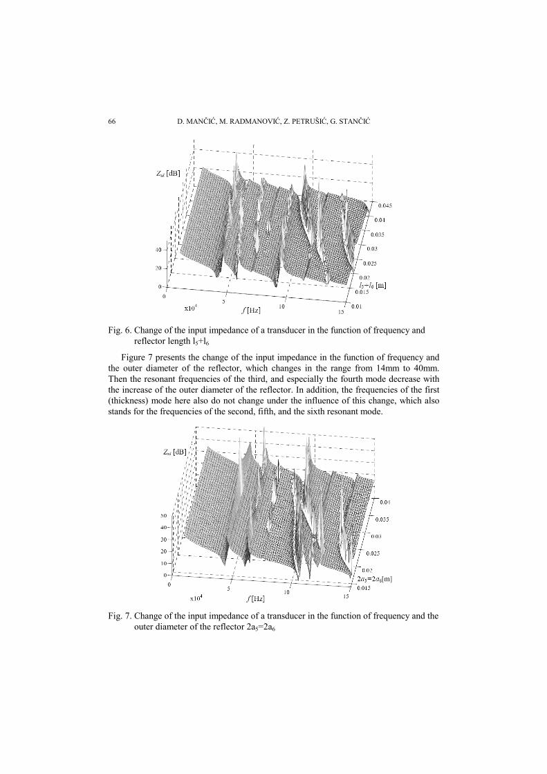
Figure 7 presents the change of the input impedance in the function of frequency and the outer diameter of the reflector, which changes in the range from 14mm to 40mm. Then the resonant frequencies of the third, and especially the fourth mode decrease with the increase of the outer diameter of the reflector. In addition, the frequencies of the first (thickness) mode here also do not change under the influence of this change, which also stands for the frequencies of the second, fifth, and the sixth resonant mode.
Fig. 7. Change of the input impedance of a transducer in the function of frequency and the
outer diameter of the reflector 2a5=2a6
Influence of Ultrasonic Transducer Acoustic Impedances and Dimensions ... 67
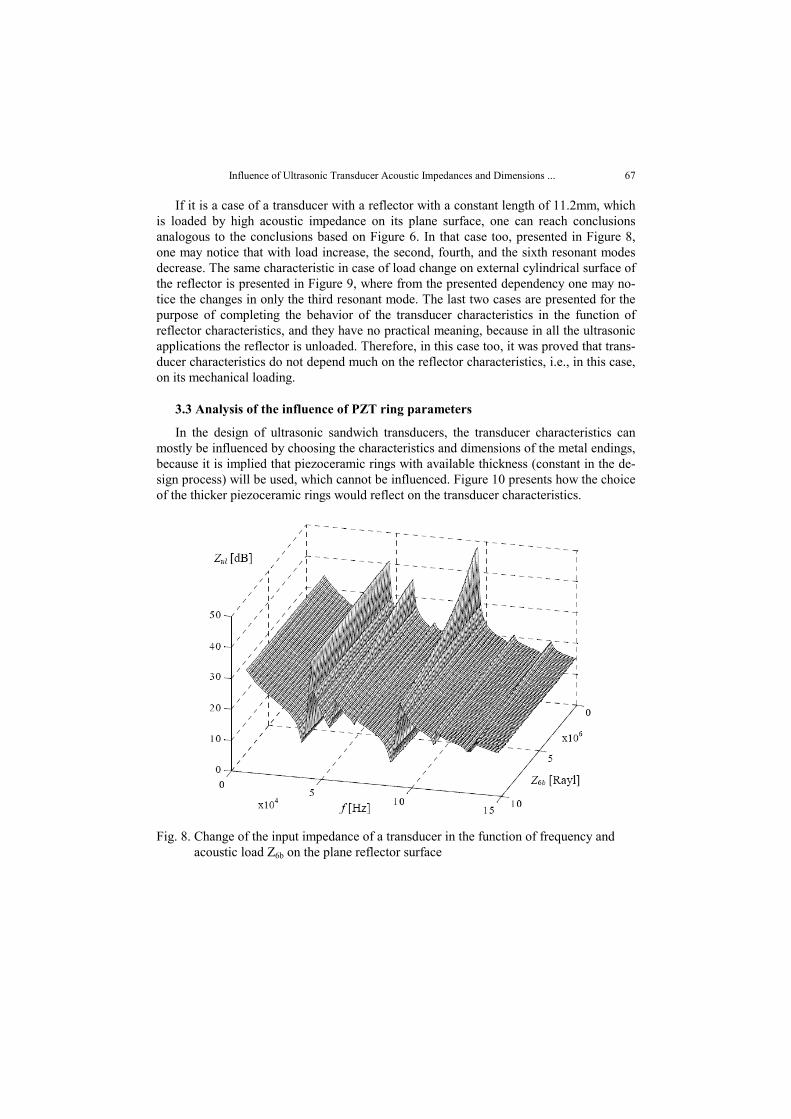
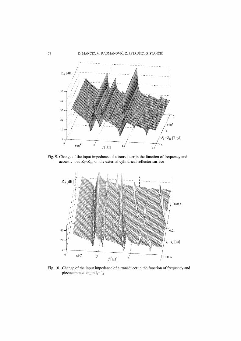
If it is a case of a transducer with a reflector with a constant length of 11.2mm, which is loaded by high acoustic impedance on its plane surface, one can reach conclusions analogous to the conclusions based on Figure 6. In that case too, presented in Figure 8, one may notice that with load increase, the second, fourth, and the sixth resonant modes decrease. The same characteristic in case of load change on external cylindrical surface of the reflector is presented in Figure 9, where from the presented dependency one may no-tice the changes in only the third resonant mode. The last two cases are presented for the purpose of completing the behavior of the transducer characteristics in the function of reflector characteristics, and they have no practical meaning, because in all the ultrasonic applications the reflector is unloaded. Therefore, in this case too, it was proved that trans-ducer characteristics do not depend much on the reflector characteristics, i.e., in this case, on its mechanical loading.
3.3 Analysis of the influence of PZT ring parameters
In the design of ultrasonic sandwich transducers, the transducer characteristics can mostly be influenced by choosing the characteristics and dimensions of the metal endings, because it is implied that piezoceramic rings with available thickness (constant in the de-sign process) will be used, which cannot be influenced. Figure 10 presents how the choice of the thicker piezoceramic rings would reflect on the transducer characteristics.
Fig. 8. Change of the input impedance of a transducer in the function of frequency and
acoustic load Z6b on the plane reflector surface
D. MANČIĆ, M. RADMANOVIĆ, Z. PETRUŠIĆ, G. STANČIĆ 68
Fig. 9. Change of the input impedance of a transducer in the function of frequency and
acoustic load Z5=Z6a, on the external cylindrical reflector surface
Fig. 10. Change of the input impedance of a transducer in the function of frequency and
piezoceramic length l1= l2
Influence of Ultrasonic Transducer Acoustic Impedances and Dimensions ... 69
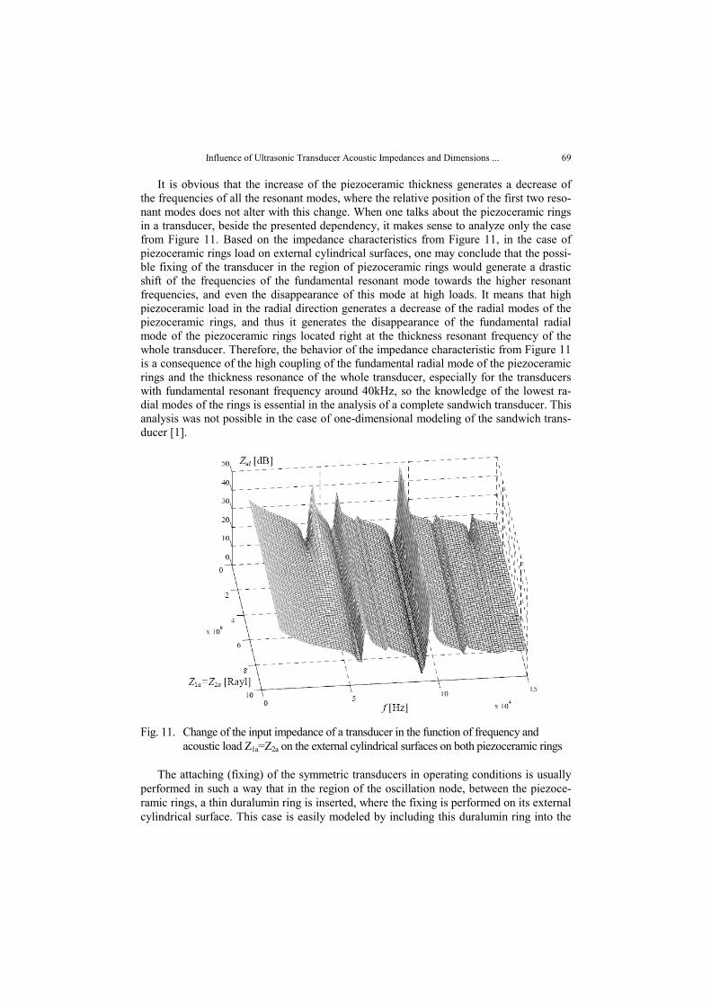
It is obvious that the increase of the piezoceramic thickness generates a decrease of the frequencies of all the resonant modes, where the relative position of the first two reso-nant modes does not alter with this change. When one talks about the piezoceramic rings in a transducer, beside the presented dependency, it makes sense to analyze only the case from Figure 11. Based on the impedance characteristics from Figure 11, in the case of piezoceramic rings load on external cylindrical surfaces, one may conclude that the possi-ble fixing of the transducer in the region of piezoceramic rings would generate a drastic shift of the frequencies of the fundamental resonant mode towards the higher resonant frequencies, and even the disappearance of this mode at high loads. It means that high piezoceramic load in the radial direction generates a decrease of the radial modes of the piezoceramic rings, and thus it generates the disappearance of the fundamental radial mode of the piezoceramic rings located right at the thickness resonant frequency of the whole transducer. Therefore, the behavior of the impedance characteristic from Figure 11 is a consequence of the high coupling of the fundamental radial mode of the piezoceramic rings and the thickness resonance of the whole transducer, especially for the transducers with fundamental resonant frequency around 40kHz, so the knowledge of the lowest ra-dial modes of the rings is essential in the analysis of a complete sandwich transducer. This analysis was not possible in the case of one-dimensional modeling of the sandwich trans-ducer [1].
Fig. 11. Change of the input impedance of a transducer in the function of frequency and
acoustic load Z1a=Z2a on the external cylindrical surfaces on both piezoceramic rings
The attaching (fixing) of the symmetric transducers in operating conditions is usually performed in such a way that in the region of the oscillation node, between the piezoce-ramic rings, a thin duralumin ring is inserted, where the fixing is performed on its external cylindrical surface. This case is easily modeled by including this duralumin ring into the
D. MANČIĆ, M. RADMANOVIĆ, Z. PETRUŠIĆ, G. STANČIĆ 70
model in Figure 1. By analyzing the load of this ring in a radial direction, on the external cylindrical surface, one may show that, in contrast to the previous case, in this case the changes of the fundamental resonant frequency of the transducer are negligible.
4. DISCUSSION
With this model it is possible to determine any transfer function of the transducer, where besides the input electric impedance, the transfer function Fi/V is most often deter-mined where Fi denotes the surface force on the observed mechanical access. Also, it is possible to perform an analysis of the sensitivity of the specific transducer characteristics to the values of the piezoelectric and elastic constants of the piezoceramic rings, as well as to the values of the metal ring parameters and bolts. In addition, as in the case of the piezoceramic rings, here too it is possible to determine the effective electromechanical coupling factor keff in the function of frequency and specific dimensions of the constituent parts for any resonant mode of the sandwich transducer. This possibility is very important, because based on the previous analysis, it is obvious that with the proposed model one may obtain a transducer with a particular resonant frequency using several length combi-nations of transducer constituent parts. However, since it is important to obtain a trans-ducer with keff, as large as possible, only some dimension combinations will enable the greatest possible ability of converting electric into the mechanical energy. Based on the previous analysis, it is possible to perform the design of an ultrasonic sandwich transducer by the proposed model for any required resonant frequency, but not for any dimension of the ratio of transducer constituent parts, yet only for those dimension combinations that allow for the largest possible emitted ultrasonic power. Therefore, using this model one may easily predict what those dimensions are.
Based on all the mentioned considerations, it is possible to make an easy selection of materials and dimensions of the sandwich transducer constituent parts. Thus, using this model it is possible to evaluate very quickly the quality of every ultrasonic transducer that should be realized.
In contrast to the former approaches in transducer design, in the input impedance analysis much attention is dedicated here to the form and the position of the higher reso-nant modes, and to the influence of the specific parameters on their behavior. The first reason for such an approach is the need for the higher, parasite modes, to have the small-est possible influence on the resonant frequency, that is, to be at the greatest possible dis-tance from it. This model enabled the determination of which length or diameter, and which constituent part, should be changed in order to realize the desired separation of modes. The second reason for analysis of the higher resonant modes is that during long practice of the transducer production, based on the form of the higher resonant modes, it was noticed that an inadequate choice of some transducer elements leads to an irregular form of some of the higher resonant modes. The analysis using the proposed model may show which dimension, and which element it is about, based on the influence of that ele-ment on the observed resonant mode. If some higher resonant mode is damped because of a design error, and if this may be noticed in the static measuring conditions applied in this analysis, regardless of whether that resonant mode is isolated from other modes, it will certainly be reflected on the characteristics of the fundamental resonant mode in dynamic operating conditions as well, regardless of whether the impedance characteristics in the
Influence of Ultrasonic Transducer Acoustic Impedances and Dimensions ... 71
vicinity of the thickness mode is satisfactory in static measuring terms. By applying this model one may determine the cause of such irregularities in the realized transducer. Dur-ing the realization of numerous transducers it was noticed that the influence of the reflec-tor on the transducer characteristics was small, so by changing the emitter characteristics, the adjusting of the resonant frequency was most often performed. This model confirmed that assumption, based on the previously performed analyses. In ultrasonic technique, the design of the transducers with entirely new frequencies and characteristics was seldom approached, due to the impossibility of analysis of different parameter influence, which is now enabled by the proposed three-dimensional model. Usually designs were finished by copying those transducers that showed satisfying characteristics in practice. This model unfolds great possibilities in solving this problem during designing new transducers.
The previous analysis of the impedance characteristics on dimensions in thickness and radial direction shows that a model is realized by means of which one may very quickly perform a synthesis, and evaluate the quality of every sandwich transducer that could be realized, which was the goal of the analysis in this paper. An ideal model, which would take into account all the parameters, boundary conditions, all the existing resonant modes, and state which the sandwich transducer characteristics depend on, cannot be realized at all, so this analysis is focused on obtaining a complete, if possible, but simple model, which, although approximate, takes into consideration as many initial parameters as pos-sible. It was showed that, although the transducer characteristics depend on many pa-rameters, the length (thickness) of the transducer constituent parts had the greatest influ-ence. In contrast to the finite element method, which is complicated for such a parameter analysis, the proposed three-dimensional model is simple. However, although the model is simple, the calculations performed to determine specific transducer characteristics are very complicated, as in the case of the determination of the transducer characteristics in this paper, or in determination of the characteristics of the piezoceramic and metal rings from the previous papers [2, 3], and this holds either for the three-dimensional model, or for the some numerical method [1]. These calculations are not presented in detail, but the procedures how certain characteristics are obtained are described, and the end results of these calculations are contained in the computer programs enclosed in literature [1]. With this model, one very quickly obtains backup information about the directions of the change of different characteristics by varying the specific parameters, which was the basic purpose of modeling in this paper, aimed at assisting the designers of new systems.
5. CONCLUSION
Most ultrasonic transducer models do not take into account the influence of the com-ponent parts dimensions and acoustic loads on the surfaces on their resonant frequency characteristics. Or if these influences are considered, sufficient attention is not paid. The fact that these influences are not negligible is shown in this paper. The analysis of a trans-ducer's component elements dimension and corresponding acoustic load in the radial and thickness direction influence on the input electric impedance is carried out in this paper for the case of axisymmetrical ultrasonic sandwich transducer oscillating. The extensive capability of the developed matrix model of an ultrasonic transducer for the analysis of resonant frequency characteristics is confirmed once more, as proved in numerous cases before.
D. MANČIĆ, M. RADMANOVIĆ, Z. PETRUŠIĆ, G. STANČIĆ 72
REFERENCES
1. M.Radmanović, D.Mančić, Design and modeling of the power ultrasonic transducers, Niš, Faculty of Electronic Engineering, 2004.
2. D.Mančić, M.Radmanović, “Piezoceramic ring loaded on each face: a three-dimensional approach”, Journal of Technical Acoustics, Vol. 2, pp. 1.1-1.7, 2002.
3. D.Mančić, M.Radmanović, “Three-dimensional matrix model of the metal rings and disks”, 49th Sympo-sium for ETRAN, Vol. II, pp. 435-438, Budva, 2005.
4. D.Mančić, M.Radmanović, “3D matrix model of the symmetrical ultrasonic sandwich transducer”, 12th International Symposium on Power Electronics Ee 2003, Novi Sad, Serbia, pp. 1-5, 2003.
5. D.Mančić, M.Radmanović, Z.Petrušić, “3D model of the asymmetrical ultrasonic sandwich transducer”, 13th International Symposium on Power Electronics Ee 2005, Novi Sad, Serbia, pp. 1-5, 2005.
UTICAJ AKUSTIČKOG OPTEREĆENJA I DIMENZIJA ULTRAZVUČNOG PRETVARAČA
NA NJEGOVU ULAZNU ELEKTRIČNU IMPEDANSU
Dragan Mančić, Milan Radmanović, Zoran Petrušić, Goran Stančić
U ovom radu razmatran je uticaj akustičkog opterećenja na svim konturnim površinama ultrazvučnog sendvič pretvarača, na njegovu ulaznu električnu impedansu. Pored toga, ulazna električna impedansa analizirana je i u funkciji dimenzija svih sastavnih delova sendvič pretvarača. Primenjen je 3D matrični model ultrazvučnih sendvič pretvarača koji su autori ranije predložili. Ovi uticaji su po prvi put razmatrani na prikazani način u analizi kompletnih snažnih ultrazvučnih sendvič pretvarača.
Ključne reči: Ultrazvučni pretvarač, Electrična impedansa, Akustička impedansa


![Presentation P3121 english V5-01 [Kompatibilitätsmodus] · • Wireless LAN Ultrasonic Search Units • Coupling wedge. • Ultrasonic transducer • RF transducer cable. Hardness](https://img.dokumen.tips/doc/110x75/5baf026609d3f22d458ba836/presentation-p3121-english-v5-01-kompatibilitaetsmodus-wireless-lan-ultrasonic.jpg)