Embed Size (px)
Citation preview

1
INF5490 RF MEMS
LN03: Modeling, design and analysis
Spring 2008, Oddvar SøråsenDepartment of Informatics, UoO

2
Today’s lecture
• MEMS functional operation– Transducer principles– Sensor principles
• Methods for RF MEMS modeling– 1. Simple mathematical models– 2. Converting to electrical equivalents– (3. Analyzing using Finite Element Methods)
• LN04

3
Transducers for (RF) MEMS
• Electromechanical transducers– Transforming
electrical energy mechanical energy• Transducer principles
– Electrostatic– Electromagnetic– Electro thermal– Piezoelectric

4
Transducer principles• Electrostatic transducers
– Principle: Forces exist between electric charges• ”Coulombs law”
– Stored energy when mechanical or electrical work is performed on the unit can be converted to the other form of energy
– The most used form of electromechanical energy conversion
– Fabrication is simple
– Often implemented using a capacitor with movable plates• Vertical movement: parallel plates• Horizontal movement: Comb structures

5
Electrostatic transducers• + Beneficial due to simplicity• + Actuation controlled by voltage
• voltage charge attractive force movement
• + Movement gives current• movement variable capacitor current when voltage is
constant: Q = V C and i = dQ/dt = V dC/dt
• ÷ Need environmental protection (dust)• Packaging required (vacuum)
• ÷ Transduction mechanism is non-linear• Gives distortions (force is not proportional to voltage)• Solution: small signal variations around a DC voltage

6
Transducer principles, contd.
• Electromagnetic transducers– Magnetic windings pull the element
• Electro thermal actuators– Different thermal expansions on different
locations due to temperature gradients• Large deflections can be obtained• Slow

7
Transducer principles, contd.• Piezoelectric transducers
– In some anisotropic crystalline materials the charges will be displaced when stressed electric field
• stress = ”mechanical stress” (Norw: “mekanisk spenning)– Similarly, strain results when an electric field is
applied• strain = ”mechanical strain” (Norw: “mekanisk tøyning”)
– Ex. PZT (lead zirconate titanates) – ceramic materials
• (Electrostrictive transducers– Mechanical deformation by electric field
• Magnetostrictive transducers– Deformation by magnetic field)

8
Comparing different transducer principles

9
Sensor principles
• Piezoresistive detection
• Capacitive detection
• Piezoelectric detection
• Resonance detection

10
Sensor principles
• Piezoresistive detection– Resistance varies due to external
pressure/stress– Used in pressure sensors
• deflection of membrane– Piezoresistors placed on membrane where
strain is maximum– Resistor value is proportional to strain– Performance of piezoresistive micro sensors
is temperature dependent

11
Pressure sensor
Senturia
12
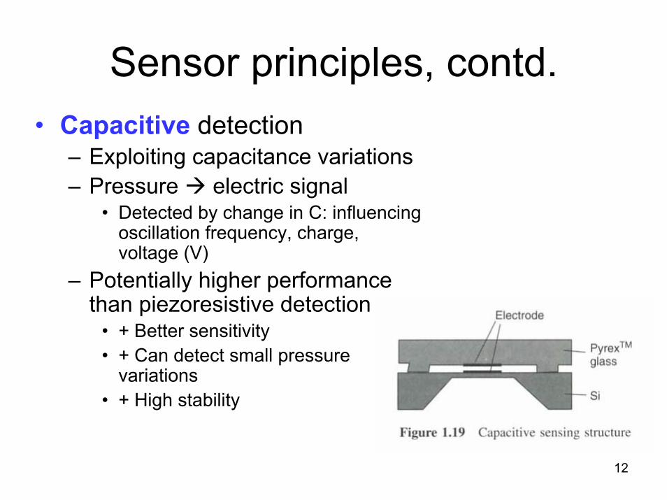
Sensor principles, contd.• Capacitive detection
– Exploiting capacitance variations– Pressure electric signal
• Detected by change in C: influencing oscillation frequency, charge, voltage (V)
– Potentially higher performance than piezoresistive detection
• + Better sensitivity• + Can detect small pressure
variations• + High stability

13
Sensor principles, contd.
• Piezoelectric detection– Electric charge distribution changed due to
external force electric field current
• Resonance detection– Analogy: stress variation on a string gives
strain and is changing the “natural”resonance frequency

14
Methods for modeling RF MEMS
• 1. Simple mathematical models– Ex. parallel plate capacitor
• 2. Converting to electrical equivalents
• 3. Analysis using Finite Element Methods

15
1. Simple mathematical models• Use equations, formulas describing the physical
phenomena– Simplification, approximations – Explicit solutions for simple problems
• linearization around a bias point– Numerical solution of the set of equations
• Typical differential equations
• + Gives the designer insight/ understanding – How the performance changes by parameter
variations– May be used for initial estimates
16
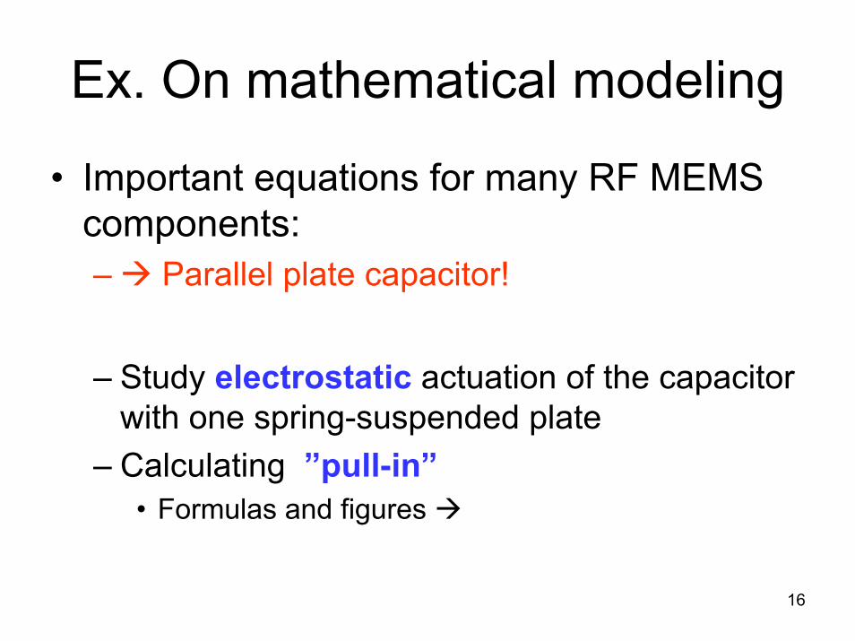
Ex. On mathematical modeling
• Important equations for many RF MEMS components: – Parallel plate capacitor!
– Study electrostatic actuation of the capacitor with one spring-suspended plate
– Calculating ”pull-in”• Formulas and figures

17
ElectrostaticsElectric force between charges: Coulombs law
+ q - q
F
r
221
041
rqqF ⋅=
πε
0qFE =Electric field = force pr. unit charge
b
b
aaba UUldFW −=⋅= ∫→Work done by a force = change in potential energy
0qUV =Potential, V = potential energy pr. unit charge
∫ ⋅=−b
aba ldEVVVoltage = potential difference

18
Capacitance
abVQC =
abV
+ Q
- Q
a
bE
A
d
Definition of capacitance
Surface charge density = σ Voltage
00
1εε
σ⋅==
AQE d
AQdEVab ⋅=⋅=
0ε
dA
VQCab
0ε==
Energy stored in a capacitor, C, that is charged to a voltage V0 at a current
dtdVCQi == &
20
020
0 2210
VdACVdvvCdt
dtdvCvdtivU
V ε==⋅=⋅⋅=⋅⋅= ∫∫ ∫

19
Parallel plate capacitor
Attractive force between plates
2
22
2)
2(
dAVV
dA
ddUF εε
=∂∂
−=∂∂
−=

20
Movable capacitor plate
• Assumptions for calculations:– Suppose air between plates– Spring attached to upper plate
• Spring constant: k– Voltage is turned on
• Electrostatic attraction– At equilibrium
• Forces up and forces down are in balance

21
Force balance
k = spring constant
deflection from start position
d0 = gap at 0V and zero spring straind = d0 – zz=d0 – d
Force on upper plate at V and d:
= 0 at equilibrium

22
Two equilibrium positions
ς = 1 – d/d0 Senturia

23
Stability
Suppose the gap decreases
• How the forces develop when d decreases– Suppose a small perturbation in the gap at constant voltage
If the upward force also deceases, the system is UNSTABLE!

24
Stability, contd.
Stability condition:
Pull-in when:

25
Pull-in
Pull-in when:

26
Pull-in
Senturia

27
2. Converting to electrical equivalents
• Mechanical behavior can be modeled using electrical circuit elements– Mechanical structure simplifications equivalent
electrical circuit• ex. spring/mass R, C, L
– Possible to “interconnect” electrical and mechanical energy domains
• Simplified modeling and co-simulation of electronic and mechanical parts of the system
– Proper analysis-tools can be used• Ex. SPICE

28
Converting to electrical equivalents, contd.
• We will discuss:– Needed circuit theory– Conversion principles
• effort - flow– Example of conversion
• Mechanical resonator
– In a future lecture:• Co-existence and coupling between various
energy domains

29
Circuit theory
• Basic circuit elements: R, C, L• Current and voltage equations for basic
elements (low frequency)– Ohms law, C and L-equations
• V = RI, I = C dV/dt, V = L dI/dt– Laplace transformation
• From differential equations to algebraic (s-polynomial)• Complex impedances: R, 1/sC, sL
• Kirchhoffs equations– Σ current into nodes = 0, Σ voltage in a loop = 0

30
Effort - flow• Electrical circuits are described by a set of
variables: conjugate power variables– Voltage V: across or effort variable– Current I: through or flow variable– An effort variable drives a flow variable through an
impedance, Z
• Circuit element is modeled as a 1-port with terminals
– Same current (f = flow) in and out and through the element• Positive flow into a terminal defining a positive effort

31
Energy-domains, analogies
• Various energy domains exist– Electric, elastic, thermal, for liquids etc.
• For every energy domain it is possible to define a set of conjugate power variables that may be used as basis for lumped component modeling using equivalent circuits elements
• Table 5.1 Senturia ->

32
Ex. of conjugate power variables

Conjugate power variables: e,f
• Assume conversion between energy domains were the energy is conserved!
• Properties– e * f = power– e / f = impedance
• Generalized displacement represents the state, f. ex. position or charge
– e * q = energy∫ +=t
t
tqdttftq0
)()()( 0)()( tqtf &=
33

34
Generalized momentum
∫ +=t
t
tpdttetp0
)()()( 0
– Mechanics: “impulse”• F*dt = mv – mv0
– General: p * f = energy

35
Ex.: Mechanical energy domainforce
velocity
position
momentum
force x time
work/time = power
force*distance = work =energy
energy

36
Ex.: Electrical energy domain
voltage
current
charge
power
energy

37
e V - convention• Senturia and Tilmans use the
e V –convention• Ex. electrical and mechanical circuits
– e V (voltage) equivalent to F (force)– f I (current) equivalent to v (velocity)– q Q (charge) equivalent to x (position)– e * f = ”power” injected into the element
H. Tilmans, Equivalent circuit representation of electromagnetical transducers:I. Lumped-parameter systems, J. Micromech. Microeng., Vol. 6, pp 157-176, 1996

38
Other conventions• Different conventions exist for defining through-
or across-variables
*alternativt

39
Generalized circuit elements• One-port circuit elements
– R, dissipating element– C, L, energy-storing elements– Elements can have a general function!
• Can be used in various energy domains

40
Generalized capacitance
Compare with a simplified case:- a linear capacitor
definition of C

41
Generalized capacitance, contd.
Capacitance is associated with stored potential energy
Co-energy:

42
Energy stored in parallel plate capacitor
CQdq
CqdqeQW
Q Q
2)(
2
0 0
=⋅=⋅= ∫ ∫Energy:
∫ ∫ =⋅⋅=⋅=V V CVdvvCdeqVW0 0
2*
2)(Co-energy:
)()(* QWVW = for linear capacitance

43
Mechanical spring
Hook´s law: xkF ⋅=
Compare with capacitor 2121)( Q
CQW ⋅⋅=
displacementdisplacement
Qx1
1/C equivalent to k
Stored energy

44
”Compliance”
• ”Compliance” = ”inverse stiffness”
• Stiff spring small capacitor• Soft spring large capacitor
kCspring
1=

45
Generalized inductanceEnergy also defined as:
Energy = stored kinetic energy

46
Ex.: Electrical inductor
Co-energy:

47
Analogy between mass (mechanical inertance) and inductance L
A mechanical system has linear momentum: p = mv
Flow:
Co-energy:

48
Analogy between m and L
Compare with:
L is equivalent to m
m = L inertance
Mechanical inertance = mass mis analog to inductance L

49
Interconnecting elements
• e V follows two basic principles
– Elements that share a common flow, and hence a common variation of displacement, are connected in series
– Elements that share a common effort are connected in parallel

50
Ex. of interconnection:
”Direct transformation”

51

52

53

54
mk
LC== 00 ,1 ωω
System without damping (b=0, R=0)

55
System without damping, contd.

56
With damping

57
Damped system, contd.

58

59
What is the meaning of ”damping time”?
Power
initial conditions

60
Q-factor and damping time
General equation
mechanical electrical

61
Amplitude at resonance for forced vibrations