Embed Size (px)
Citation preview

Industrial Wastewater: Permitted and Prohibited Discharge Reference Department: Environmental Protection Program: Industrial Wastewater Owner: Program Manager, Darrin Gambelin Authority: ES&H Manual, Chapter 43, Industrial Wastewater SLAC’s industrial wastewater permits are explicit about the type and amount of wastewater that can enter the sanitary sewer, and all 20 permitted discharges are described in this exhibit. The permits are also explicit about which types of discharges are prohibited, and these are itemized as well. Any industrial wastewater discharges not listed below must first be cleared with the industrial wastewater (IW) program manager before discharge to the sanitary sewer. Any prohibited discharge must be managed by the Waste Management (WM) Group. (See Industrial Wastewater: Discharge Characterization Guidelines.1)
Permitted Industrial Discharges Each of the twenty industrial wastewater discharges currently named in SLAC’s permits is listed below by their permit discharge number (left column) and each is described in terms of process description, location, flow, characterization, and point of discharge on the page number listed on the right.
1 Metal Finishing Pretreatment Facility 4 2 Former Hazardous Waste Storage Area Dual Phase Extraction 5 3 Low-conductivity Water from Cooling Systems 6 4 Cooling Tower Blowdown 8 5 Monitoring Well Purge Water 10 6 Rainwater from Secondary Containments 11
1 Industrial Wastewater: Discharge Characterization Guidelines (SLAC-I-750-0A16T-007), http://www-
group.slac.stanford.edu/esh/eshmanual/references/iwGuideDischarge.pdf
1 Feb 2007 (updated 1 Feb 2007) SLAC-I-750-0A16T-006-R000 1 of 28

Industrial Wastewater: Permitted and Prohibited Discharge Reference 7 Groundwater from Underground Sumps and Vaults 12 8 Soapy Low-conductivity Water 14 9 Low-conductivity Water from Wet-blasting Operation 15 10 Low-conductivity Water from Klyston Tubes 16 11 Test Stand Cooling Water 17 12 Chiller Flushing 18 13 Former Solvent Underground Storage Tank Groundwater Treatment Facility 19 14 Steam Cleaning Pad and Oil-Water Separator at Motor Pool 20 15 Photographic Processing 22 16 Cafeteria 23 17 Metallography Neutralization Tanks 24 18 Backflushing of Sand Filters for Vacuum-Pump Cooling System 26 19 Klystron Tube Washer 27 20 Precision Bench Grinding of Bulk Silicon 28
Prohibited Discharges SLAC’s permit stipulates that no discharge may enter the sanitary sewer that may cause
• Danger to human life or safety • Fire or explosion • Introduction of hazardous waste to be discharged to the sanitary sewer • Odors, air pollution, or any noxious, toxic, or malodorous gas or substance, or gas
producing substances • Flow obstruction or injury to the sewerage facilities • Interference or overloading of the wastewater treatment or reclamation process, or
sewerage facilities, or excessive costs, or use of a disproportionate share of the capacity of the sewerage facilities
• A detrimental environmental impact or nuisance, e.g., any discharge containing detectable levels of polychlorinated biphenyls
• Dilution of a discharge of waste or wastewater as a substitute for adequate treatment • Inhibition of maintenance or operation of the sewerage facilities • Any adverse action that impacts the ability of the sewage treatment plant to protect
the San Francisco Bay
1 Feb 2007 (updated 1 Feb 2007) SLAC-I-750-0A16T-006-R000 2 of 28

Industrial Wastewater: Permitted and Prohibited Discharge Reference
For help in characterizing any potential hazard and how best to discharge, treat, or remove it, contact the IW program manager.
Itemized SLAC Permitted Discharges Details for permitted discharges follow on the following pages.
1 Feb 2007 (updated 1 Feb 2007) SLAC-I-750-0A16T-006-R000 3 of 28

Industrial Wastewater: Permitted and Prohibited Discharge Reference
1 Metal Finishing Pretreatment Facility
Description The Metal Finishing Pretreatment Facility (MFPF) pretreats
• All wastewaters associated with the Plating Shop operations. Operations and equipment include: process tanks (including cyanide room tanks), air scrubbers, laboratory sinks, effluent from the regeneration of de-ionized water, and steam-cleaning runoff.
• Non-hazardous wastewaters generated by flushing heat-exchanger and cooling system piping. The metal content determines if pretreatment is required.
• Solutions from the regeneration of de-ionized water • Miscellaneous non-hazardous wastewaters that require pH adjustment or reduction of
metals concentrations in order to meet permit limits. Flow Period
Estimated Gallons
Daily (avg. daily flow July ‘02-June ‘03)
4,000
Weekly (5day) 20,000
Monthly 100,000
Annual 1,200,000
Location Building 38, west of the Heavy Fabrication Building (Building 26) and east of the Plating Shop (Building 25) and the Chemical Storage Area (Building 36)
Flow The MFPF operates continuously during normal business hours, typically for an 8-hour shift, and may be operated off-hours as needed. Along with analytical results, monthly averages and maximum flow per month are reported to the South Bayside System Authority (SBSA) every six months in the required semiannual self-monitoring report.
Characterization Industrial wastewater containing low concentrations of metals, pre-treated to meet all mandatory wastewater discharge permit requirements.
Point of Discharge Treated wastewater overflows a weir at the top of the clarifier. This flow is hard-plumbed to the sanitary sewer at the north end of the MFPF.
1 Feb 2007 (updated 1 Feb 2007) SLAC-I-750-0A16T-006-R000 4 of 28

Industrial Wastewater: Permitted and Prohibited Discharge Reference
2 Former Hazardous Waste Storage Area Dual Phase Extraction
Description The Former Hazardous Waste Storage Area (FHWSA) Dual Phase Extraction System (DPE) is designed to reduce the concentrations of VOCs and SVOCs in soil, groundwater and soil vapor at the FHWSA site and reduce lateral migration of impacted groundwater. The DPE system utilizes 19 groundwater/soil vapor extraction wells and four vacuum-enhanced groundwater extraction wells. Extracted groundwater is treated by an air stripper and discharged after treatment into the sanitary sewer. Extracted soil vapors are discharged unabated to the atmosphere under a permit issued by the BAAQMD.
Location Near Building 15
Flow Maximum Process Flow / Period Gallons
Daily 15,120
Quarterly 232,050
Annually 928,200
The system operates 24 hrs a day, sevens days a week
Characterization: Treated groundwater from a former hazardous waste storage area
Point of Discharge: The FHWSA is located in an enclosure near Building 15. It discharges to the Alpine Road sanitary sewer line.
1 Feb 2007 (updated 1 Feb 2007) SLAC-I-750-0A16T-006-R000 5 of 28

Industrial Wastewater: Permitted and Prohibited Discharge Reference
3 Low-conductivity Water from Cooling Systems
Description Operation of SLAC’s electron accelerator generates considerable heat, which is absorbed by low conductivity water (LCW) circulating through flanges, jackets, and pipes around the accelerator tube in closed-loop configurations. The heat is later transferred from the LCW in closed-loop systems to domestic water open-air cooling systems, and is ultimately dissipated to the atmosphere by evaporation in induced-draft cooling towers. The accelerator and its support equipment are served by numerous independent cooling systems throughout SLAC.
LCW is generated at the deionized water plant in Building 461. Domestic water is processed by an ion-exchange system that maintains the conductivity at or below 8 meg-ohms, resulting in relatively high-purity water. Flow Gallons
Daily 350
Weekly (5day) 1750
Monthly 7000
Annual 84,000
SLAC has approximately 130 circulating systems, ranging in capacity from several hundred gallons to 50,000 gallons. Systems are frequently drained for maintenance and installation of new equipment. A system of average size holds approximately 2000 gallons. Typically, a section requiring maintenance or repair can be valved off, allowing only a small part of the system to be drained.
A storage tank network is in place to contain spilled or leaking water from cooling systems in the Klystron Gallery. The network comprises ten 350-gallon plastic tanks installed along the north side of the Gallery. Each tank is sampled for radioanalysis prior to discharge.
Location LCW systems are located throughout SLAC.
Flow
Characterization LCW contains very low concentrations of heavy metals; primarily copper from the piping. This discharge may contain extremely low levels of radioactivity which are
1 Feb 2007 (updated 1 Feb 2007) SLAC-I-750-0A16T-006-R000 6 of 28

Industrial Wastewater: Permitted and Prohibited Discharge Reference within state and federal regulations for discharge into the sanitary sewer. Each batch of potentially radioactive LCW is sampled for radioanalysis prior to discharge to ensure compliance with all applicable discharge requirements.
Point of Discharge Because this is a facility-wide activity, discharge locations are to the sanitary sewer connection closest to the system or section being drained.
1 Feb 2007 (updated 1 Feb 2007) SLAC-I-750-0A16T-006-R000 7 of 28

Industrial Wastewater: Permitted and Prohibited Discharge Reference
4 Cooling Tower Blowdown
Description LCW circulates through the cooling water system, drawing heat from various sources such as air conditioners and experimental equipment, and expelling the heat at cooling towers. The LCW remains contained in pipes and is cooled with circulated domestic water via counter-current heat exchangers. The circulated domestic water within the tower’s bulk water system becomes heated and evaporates, which concentrates the amount of dissolved solids and increases the problems of corrosion, scaling and fouling.
The Conventional and Experimental Facilities (CEF) Department apply water treatment chemicals to control the problems of corrosion, scaling and bio-fouling. Corrosion affects the metal pipes and components of the system. Sulfuric acid is used to adjust the pH of the alkaline domestic water used at SLAC. Scaling affects the transfer pipes and pumps, hindering the efficiency of the system. Variables such as hardness, pH, temperature and alkalinity determine the amount of scaling and each must be controlled. The chemicals are dispensed using an automated system to minimize both handling and quantities of additives required. Both CEF and ESH maintain material safety data sheets (MSDSs) for these chemicals, which are specifically formulated to break down soon after application.
Flow Gallons
Daily 13,000
Weekly (7 days)
90,000
Monthly 420,000
Annual 5,000,000 Location
CT-101 is located along the Loop Road south of Building 44 (Test Laboratory). CT-1701 is located south of End Station B, adjacent to the Research Yard along the Klystron Gallery, CT-1200 is at Sector 1 (west end of the linac), CT-1201 is at Sector 9, and CT-1202 is at Sector 22 (just west of I-280). CT-015 is a small unit for local use and is located behind Building 15. The newest cooling tower, CT-404, is located in the northeast corner of the Research Yard, adjacent to Beam Dump East.
Flow SLAC discharges blowdown water from the cooling towers to the sanitary sewer. Blowdown volume and frequency are dependent on research activities, climatic conditions, and the characteristics of the makeup water.
1 Feb 2007 (updated 1 Feb 2007) SLAC-I-750-0A16T-006-R000 8 of 28

Industrial Wastewater: Permitted and Prohibited Discharge Reference Characterization Blowdown water with elevated concentrations of suspended and dissolved solids, and low concentrations of chemicals added to inhibit corrosion, scaling, and fouling of cooling-system piping.
Point of Discharge Each of the seven cooling towers is connected to the sanitary sewer.
1 Feb 2007 (updated 1 Feb 2007) SLAC-I-750-0A16T-006-R000 9 of 28
Industrial Wastewater: Permitted and Prohibited Discharge Reference
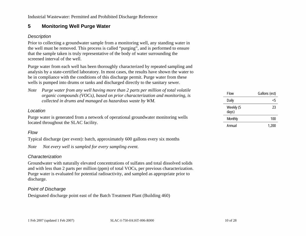
5 Monitoring Well Purge Water
Description Prior to collecting a groundwater sample from a monitoring well, any standing water in the well must be removed. This process is called “purging”, and is performed to ensure that the sample taken is truly representative of the body of water surrounding the screened interval of the well.
Purge water from each well has been thoroughly characterized by repeated sampling and analysis by a state-certified laboratory. In most cases, the results have shown the water to be in compliance with the conditions of this discharge permit. Purge water from these wells is pumped into drums or tanks and discharged directly to the sanitary sewer.
Note Purge water from any well having more than 2 parts per million of total volatile organic compounds (VOCs), based on prior characterization and monitoring, is collected in drums and managed as hazardous waste by WM.
Flow Gallons (est)
Daily <5
Weekly (5 days)
23
Monthly 100
Annual 1,200
Location Purge water is generated from a network of operational groundwater monitoring wells located throughout the SLAC facility.
Flow Typical discharge (per event): batch, approximately 600 gallons every six months
Note Not every well is sampled for every sampling event.
Characterization Groundwater with naturally elevated concentrations of sulfates and total dissolved solids and with less than 2 parts per million (ppm) of total VOCs, per previous characterization. Purge water is evaluated for potential radioactivity, and sampled as appropriate prior to discharge.
Point of Discharge Designated discharge point east of the Batch Treatment Plant (Building 460)
1 Feb 2007 (updated 1 Feb 2007) SLAC-I-750-0A16T-006-R000 10 of 28

Industrial Wastewater: Permitted and Prohibited Discharge Reference
6 Rainwater from Secondary Containments
Description Rainwater collects in many types of secondary containment installed around onsite electrical equipment, storage tanks, chemical storage areas, and others structures. These containments are monitored for rainwater accumulation and evacuated by a vacuum truck with a 2,000-gallon tank. The water is processed through a non-hazardous water treatment unit, which uses activated carbon canisters to remove organics and solids and is equipped with a 100-micron prefilter. The water is then discharged into the reservoir of Cooling Tower 1701 for re-use in cooling operations.
Location Secondary containment through SLAC Flow Gallons
Daily 415
Weekly (7 days)
2,083
Monthly 8,333
Annual 100,000
Flow Flow is highly seasonal, depending primarily on rainfall. The regulatory wet season is October 1 through May 31. Individual containment capacities range from several gallons to several thousand gallons. A typical “significant” rain event – defined as delivering more than 0.1 inch of rainfall – produces an estimated 10,000 to 20,000 gallons of containment water. As noted above, the following values are for discharge of treated effluent into the cooling-tower system, not directly into the sanitary sewer.
Characterization Non-hazardous treated rainwater accumulated in secondary containments and potentially exposed to PCBs, metals, petroleum hydrocarbons, and other contaminants. Other non-hazardous water batches (for example, water used to decontaminate sampling equipment) may be processed through the treatment unit as appropriate for re-use in the cooling tower.
Point of Discharge East side of Cooling Tower 1701, south of Research Yard
1 Feb 2007 (updated 1 Feb 2007) SLAC-I-750-0A16T-006-R000 11 of 28

Industrial Wastewater: Permitted and Prohibited Discharge Reference
7 Groundwater from Underground Sumps and Vaults
Description SLAC has many underground buildings, vaults, and other structures that extend below the elevation of the groundwater table, at least during the wet season. Groundwater entering these structures either flows directly into the sanitary sewer, or is pumped out and processed through the non-hazardous water treatment unit prior to re-use in Cooling Tower 1701.
Tunnels Groundwater collects in sumps in tunnels, and must be removed continually to protect sensitive electronic equipment.
Flow Gallons
Daily 18,000
Weekly (7 days)
126,000
Monthly 504,000
Annual 6,048,000
Vaults Accumulated groundwater is removed from electrical vaults and other structures as needed, usually to facilitate access for repair work or to allow, for example, cable pulling to occur.
Location Primary underground structures include the linear accelerator (linac), the SLAC Linear Collider (SLC), the Positrion-Electron Project (PEP) and the Stanford Positron-Electron Asymmetric Ring (SPEAR) at the Stanford Synchrotron Research Laboratory (SSRL). In addition, numerous underground tunnels and electrical utility vaults exist throughout the site.
Flow
Characterization Groundwater with elevated concentrations of sulfates, total dissolved solids, and calcium hardness. Samples are collected regularly for radioanalysis to monitor this flow.
1 Feb 2007 (updated 1 Feb 2007) SLAC-I-750-0A16T-006-R000 12 of 28

Industrial Wastewater: Permitted and Prohibited Discharge Reference Point of Discharge Because this is a facility-wide activity, discharge locations are to the sanitary sewer connection closest to the sump or vault being drained.
1 Feb 2007 (updated 1 Feb 2007) SLAC-I-750-0A16T-006-R000 13 of 28

Industrial Wastewater: Permitted and Prohibited Discharge Reference
8 Soapy Low-conductivity Water
Description Operational testing of klystron pulse tanks uses ionized water as an electrical load. Soap is added to low-conductivity water (LCW) to form ionized water. Adjustment of the load impedance is a trial and error process accomplished by varying the relative proportions of soap and LCW. Periodically, the solution of soapy LCW is partially drained from the tank in order to balance the system.
Location Building 44 (Test Lab), just outside Room 165
Flow Flow Gallons
Daily 15
Weekly (5 days)
75
Monthly 300
Annual 3600
Characterization A solution of LCW containing between five and 20 percent Arm and Hammer baking soda laundry detergent
Point of Discharge Hard-plumbed connection to the sanitary sewer in southeast region of Building 44
1 Feb 2007 (updated 1 Feb 2007) SLAC-I-750-0A16T-006-R000 14 of 28

Industrial Wastewater: Permitted and Prohibited Discharge Reference
9 Low-conductivity Water from Wet-blasting Operation
Description Radio-frequency (RF) windows in klystrons are made by brazing aluminum oxide (Al2O3) to copper ring in a stainless-steel housing. The RF windows are cleaned periodically in a wet-blaster, using a mixture of LCW and Al2O3. The wet-blaster contains approximately 50 gallons of LCW in a semi-closed, re-circulating system. The LCW reservoir must be drained and replaced every one to two months, depending on usage. The drained LCW is discharged to the sanitary sewer.
In addition, every three to six months both the LCW and the Al2O3 are drained, and the blaster itself is cleaned. The Al2O3 is allowed to settle out of the water and is disposed of as hazardous waste after the water is decanted from the bucket. Settling is performed after each use, as well. The LCW is discharged to the sanitary sewer. Flow Gallons
Daily 0.2
Weekly (5 days)
1
Monthly 5
Annual 60
Location Building 23, Room 101-B; southeast of Building 44 (Test Lab)
Flow
Characterization LCW with traces of Al2O3, copper and stainless steel
Point of Discharge Sink in Building 123
1 Feb 2007 (updated 1 Feb 2007) SLAC-I-750-0A16T-006-R000 15 of 28

Industrial Wastewater: Permitted and Prohibited Discharge Reference
10 Low-conductivity Water from Klyston Tubes
Description Klystron tube assemblies are routinely modified and repaired. One gallon LCW circulates in the lower pulse tank of each klystron in a closed-loop re-circulating system. Upon disassembly of a pulse tank, the LCW is drained. As a precaution, any klystron removed from a Radioactive Materials Management Area (RMMA) is surveyed for radioactivity prior to disassembly. However, klystron water has never shown detectable radioactivity. Should radioactivity be detected, the Radiation Protection Department (RP) will coordinate disposal of the water in accordance with applicable state and federal regulations. Approximately one tank per day is disassembled and drained.
Location Flow Gallons
Daily 0.6
Weekly (5 days)
3
Monthly 12
Annual 144
Tanks are disassembled in Rooms 165 and 170 in Building 44 (Test Lab).
Flow
Characterization Non-radioactive, uncontainment low-conductivity water (LCW)
Point of Discharge Sink in Building 44, Room 170
1 Feb 2007 (updated 1 Feb 2007) SLAC-I-750-0A16T-006-R000 16 of 28

Industrial Wastewater: Permitted and Prohibited Discharge Reference
11 Test Stand Cooling Water
Description Fully dressed klystron and other research and development units are operationally tested after assembly before being returned to service. Low-conductivity water (LCW) is circulated through each unit under pressure in a closed-loop cooling system. When the cooling system is not in use, some LCW is drained in order to relieve pressure on the gauging system.
Location Building 44 (Test Lab).
Flow Flow Gallons
Daily 0.4
Weekly (5 days)
2
Monthly 8
Annual 100
Characterization LCW
Point of Discharge Hard-plumbed connection to sanitary sewer in central western area inside Building 44
1 Feb 2007 (updated 1 Feb 2007) SLAC-I-750-0A16T-006-R000 17 of 28

Industrial Wastewater: Permitted and Prohibited Discharge Reference
12 Chiller Flushing
Description Chilled water is used at SLAC for various purposes, but primarily to cool research and operational equipment. Two large chillers are housed in Building 23 (the Central Utility Building) and supply the facility with chilled water. The chillers’ copper piping system is cleaned once or twice each year, and the spent solution is discharged to the sanitary sewer.
Location Building 23 (Central Utility Building)
Flow Flow Gallons
Daily 5
Weekly (5 days)
25
Monthly 100
Annual 1,200
Characterization Domestic water. The characterization data show this discharge to be well within permit limits for metals and pH.
Point of Discharge Floor drain in Building 23, underneath chiller
1 Feb 2007 (updated 1 Feb 2007) SLAC-I-750-0A16T-006-R000 18 of 28

Industrial Wastewater: Permitted and Prohibited Discharge Reference
13 Former Solvent Underground Storage Tank Groundwater Treatment Facility
Description A low-flow pump-and-treat facility operates near the site of a former solvent underground storage tank (FSUST) along the west side of Building 35. (Spent organic solvents were once pumped into the FSUST, which deteriorated over time and released contents to the surrounding soil.) The pump-and-treat facility removes volatile and semi-volatile organic compounds from groundwater. Extracted groundwater is filtered through canisters of granular activated carbon and then discharged to the sanitary sewer. Effluent from the system is sampled and analyzed on a quarterly basis.
Location Flow Gallons
Daily 250
Weekly (7 days)
1,750
Monthly 7,000
Annual 91,250
Building 35 (Plant Maintenance and Utility Shops Buildings)
Flow
Characterization Treated groundwater with very low levels of volatile organic compounds (VOCs)
Point of Discharge Hard-plumbed connection to sanitary sewer
1 Feb 2007 (updated 1 Feb 2007) SLAC-I-750-0A16T-006-R000 19 of 28

Industrial Wastewater: Permitted and Prohibited Discharge Reference
14 Steam Cleaning Pad and Oil-Water Separator at Motor Pool
Description Motor pool personnel wash vehicles and equipment and steam-clean parts on an unroofed concrete pad adjacent to Building 81 (General Services Building). This facility provides centralized cleaning services for the entire range of vehicles used on-site, which includes mobile cranes, forklifts and other heavy equipment, passenger cars, and trucks.
The steam-cleaning unit (VNG4-20021B) uses only domestic water and soap or detergent. Its flow capacity is 3.9 gallons per minute. Steam cleaning and stormwater run off from the steam cleaning pad flow into a below-grade sump via the central slot drain. The sump is connected to the oil-water separator (OWS).
The sewer-discharge OWS (Alpha-3100D) is equipped with an ozone generator, a polishing sheen filter pack, an oil surface skimmer, and a 600 gallon polyethylene clarifier/settling tank. Run-off from the pad is pumped from the sump into the settling tank to remove particulates, then processed through the OWS, and finally discharged to the sanitary sewer. The OWS unit is serviced periodically. The accumulated sludge is disposed of as hazardous waste.
Maximum Process Flow / Period Gallons
Daily 500
Weekly (5 days)
2500
Monthly 10,400
Annual (50 weeks)
125,000
Location The steam cleaning pad and oil-water separator unit is located outside, adjacent to south-east corner of Building 81, immediately south of the motor-pool vehicle service bays.
Flow Maximum daily process flow from the steam cleaning pad was estimated to be approximately 500 gallons per day based on information provided by Fleet Services and the following assumptions:2
2 Storm run-off also enters this system but is not included as process water. SLAC meteorological data
indicate that maximum rainfall intensity over a 5-day work week could produce up to approximately 1,000 gallons of runoff from the steam cleaning pad:
Maximum rainfall recorded at SLAC = 7.9 inches per with a 5-day period (Feb. 3 -7, 1998) = 0.13 feet per day
1 Feb 2007 (updated 1 Feb 2007) SLAC-I-750-0A16T-006-R000 20 of 28

Industrial Wastewater: Permitted and Prohibited Discharge Reference • Steam-cleaning delivery rate = 3.9 gpm • Maximum cleaning time per vehicle = 30 minutes • Water used per vehicle = 117 gallons • Maximum daily use of wash pad = 2 hours per day • Maximum discharge per day = 468 gallons per day (gpd)
Characterization Domestic water containing mild detergent and trace amounts of oil and metals.
Point of Discharge Treatment unit is hard-plumbed sanitary sewer connection at Building 081.
Wash pad area (40’ x 25’) = 1000 square feet Maximum storm run off (0.13 ft. x 1000 sq. ft.) = 130 cubic feet per day = 972.5 gpd
1 Feb 2007 (updated 1 Feb 2007) SLAC-I-750-0A16T-006-R000 21 of 28

Industrial Wastewater: Permitted and Prohibited Discharge Reference
15 Photographic Processing
Description X-ray films are developed at an on-site photographic processing laboratory for the Stanford Synchrotron Research Laboratory (SSRL). The process uses domestic water and involves a series of alternating baths and rinses.
Immediately after being exposed, photographic print paper is dipped in the following sequence: developer solution, first rinse, fixer solution, final rinse. Both rinse trays are fed by a constant stream of domestic water when in use, which discharges to the sanitary sewer via the lab sink. Spent fixer is collected and removed for off-site disposal, while spent developer is discharged to the sanitary sewer. Small quantities of the developer and fixer solutions are removed during rinsing, and so enter the sanitary sewer with the rinse effluent. Flow Period
Estimated Gallons
Daily 5
Weekly (5 days)
25
Monthly 100
Annual 1,200
Approximately 90% of the fixer used is recovered, with only 10% being discharged to the sanitary sewer in the rinse water.
Location SSRL Building 120, ground floor
Flow Approximately 10 gallons per hour when lab is in use
Characterization Domestic water with low concentrations of photographic fixer and higher concentrations of developer
Point of Discharge Sink in Building 120
1 Feb 2007 (updated 1 Feb 2007) SLAC-I-750-0A16T-006-R000 22 of 28

Industrial Wastewater: Permitted and Prohibited Discharge Reference
16 Cafeteria
Description The on-site cafeteria produces wastewater associated with food preparation and dishwashing. This water passes through a grease trap before entering the sanitary sewer. The grease trap is inspected every 4 to 6 weeks by field personnel from the West Bay Sanitary District (WBSD).
Location Cafeteria (Building 42)
Flow
Flow Period Gallons
Daily 300
Weekly (5 days)
1,500
Monthly 6,000
Annual 72,000
Characterization Domestic water mixed with food waste
Point of Discharge Sink and dishwasher drain in the cafeteria (Building 42)
1 Feb 2007 (updated 1 Feb 2007) SLAC-I-750-0A16T-006-R000 23 of 28
Industrial Wastewater: Permitted and Prohibited Discharge Reference
17 Metallography Neutralization Tanks
Description Metallographic sample preparation normally requires a specific sequence of operations which includes sectioning, mounting, grinding, polishing, cleaning and etching. The metallography neutralization tanks are used in the etching process step. Samples are cleaned with two types of commercially available dishwashing soap and tap water. In most cases, chemical etching is required because a polished specimen will not exhibit its microstructure because incident light is uniformly reflected. Only features which exhibit differences greater than 10% reflectivity can be viewed without etching.
Chemical etching of metallic specimens involve oxidation and reduction reactions. Standard acids and bases are used to make the etching solution. Metals in contact with the solution have a tendency to become ionized by releasing or losing electrons into solution. Metallic elements react individually according to their electron affinity. Some elements, preceding hydrogen on the electromotive activity scale, are attacked by acids alone. All elements following hydrogen cannot be attacked without the addition of an oxidizing agent. Thus, microstructure elements are attacked at different rates and this produces differential etching which produces microstructure contrast.
The etching procedure, performed inside a fume hood, uses a small amount of acid mixture (primarily sulfuric acid, <1 ml/sample) on a cotton ball to wipe the metal sample (copper, stainless or aluminum). After a few seconds, etching is stopped with flowing tap water in the sink. The cotton ball goes to hazardous waste disposal. Ethanol (<1ml/sample) is sprayed onto the wet sample and blown dry with nitrogen gas in the fume hood. The rinse water effluent from the sink passes through a neutralization tank prior to entering the sanitary sewer. The effluent pH is monitored quarterly, immediately downstream of the tank using semi-quantitative litmus paper.
According to the written procedure provided by the metallography laboratory, each tank is inspected quarterly and limestone chips are added as necessary to ensure that the height of the chips is above the water level.
1 Feb 2007 (updated 1 Feb 2007) SLAC-I-750-0A16T-006-R000 24 of 28

Industrial Wastewater: Permitted and Prohibited Discharge Reference Location The laboratory fume hood is located downstairs in Building 040, G140. The tanks are at two locations:
1. Primary location: south end of room G144, serving the fume-hood sink in G140
2. Secondary location: northwest corner of room G144 (rarely used, in conjunction with a second fume hood in G144)
Flow
Characterization Effluent from this process may contain metal particles and dissolved metal. Effluent from the neutralization tank is sampled on a monthly basis while under running water, simulating the process used in the laboratory. The effluent contained low levels of metals (in the parts per billion range) and had a pH between 6.5 and 8.5 after pre-treatment. Flow Period
Estimated Gallons
Daily 1
Weekly (5 days)
5
Monthly 20
Annual (50 weeks)
250
Oxygen-free electrolytic copper (OFE) is the primary metal analyzed in the metallographic laboratory, but occasionally stainless steel or aluminum is prepared. The effluent stream of a chemical etching process will contain ionized metals in solution similar in composition to the metal being etched. The waste stream should contain trace amounts Cu 2+, Fe 3+, Al 3+, Cr 3+, Ni 2+, and Mn 2+.
A log is maintained documenting the monthly neutralization bed inspections and maintenance. The log record contains the inspection date, pH value, and other pertinent comments.
Point of Discharge Hooded sinks discharge to neutralization tanks (G140 and G144). Neutralization tanks are hard plumbed to the sanitary sewer.
1 Feb 2007 (updated 1 Feb 2007) SLAC-I-750-0A16T-006-R000 25 of 28
Industrial Wastewater: Permitted and Prohibited Discharge Reference
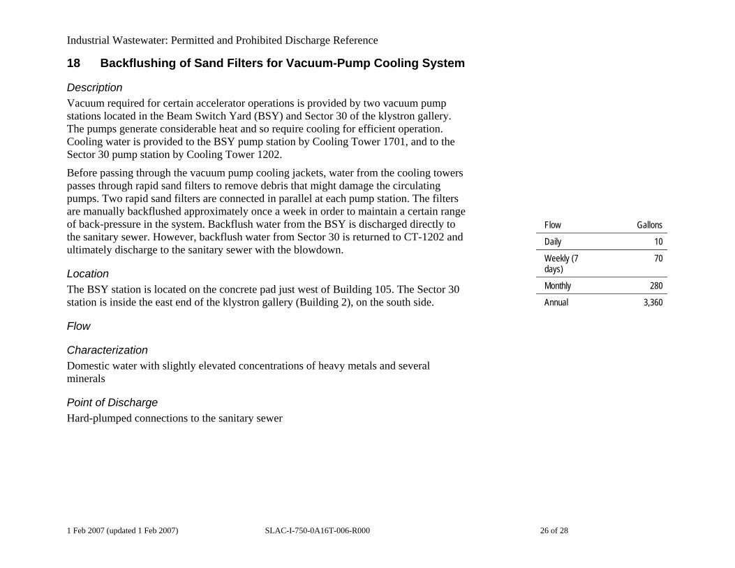
18 Backflushing of Sand Filters for Vacuum-Pump Cooling System
Description Vacuum required for certain accelerator operations is provided by two vacuum pump stations located in the Beam Switch Yard (BSY) and Sector 30 of the klystron gallery. The pumps generate considerable heat and so require cooling for efficient operation. Cooling water is provided to the BSY pump station by Cooling Tower 1701, and to the Sector 30 pump station by Cooling Tower 1202.
Before passing through the vacuum pump cooling jackets, water from the cooling towers passes through rapid sand filters to remove debris that might damage the circulating pumps. Two rapid sand filters are connected in parallel at each pump station. The filters are manually backflushed approximately once a week in order to maintain a certain range of back-pressure in the system. Backflush water from the BSY is discharged directly to the sanitary sewer. However, backflush water from Sector 30 is returned to CT-1202 and ultimately discharge to the sanitary sewer with the blowdown.
Flow Gallons
Daily 10
Weekly (7 days)
70
Monthly 280
Annual 3,360
Location The BSY station is located on the concrete pad just west of Building 105. The Sector 30 station is inside the east end of the klystron gallery (Building 2), on the south side.
Flow
Characterization Domestic water with slightly elevated concentrations of heavy metals and several minerals
Point of Discharge Hard-plumped connections to the sanitary sewer
1 Feb 2007 (updated 1 Feb 2007) SLAC-I-750-0A16T-006-R000 26 of 28

Industrial Wastewater: Permitted and Prohibited Discharge Reference
19 Klystron Tube Washer
Description The following process describes the cleaning of the ceramic high-voltage seal at the bottom of a klystron tube:
1. Remove klystron bottom, which is essentially a 15-gallon tank filled with mineral oil.
2. Wipe excess oil from outside of high-voltage seal of gun assembly with citrus-based solvent on rag.
3. Spray outside of high-voltage seal with a turpine surfactant-mixture aerosol (“Cut-Through”).
4. Using crane, place high-voltage gun assembly in washer: a 30-gallon tank equipped with spray nozzles. Flow Gallons
Daily 30
Weekly (5 days)
150
Monthly 600
Annual 7,200
5. Mix a small amount of mild detergent into 15 gallons of hot LCW and circulate through jets in washer for several minutes.
The cleaning tank effluent is tested for PCBs and, if none are detected, discharged to the sanitary sewer.
Location Building 44 (Test Lab)
Flow
Characterization Domestic water containing low concentrations of mineral oil and various water-based cleaning agents within mandatory wastewater discharge permit requirements.
Point of Discharge Hard-plumped connections in Building 44
1 Feb 2007 (updated 1 Feb 2007) SLAC-I-750-0A16T-006-R000 27 of 28

Industrial Wastewater: Permitted and Prohibited Discharge Reference
20 Precision Bench Grinding of Bulk Silicon
Description The discharge water from the precision bench grinding of bulk silicon crystal (for use in the X-Ray Monochromators at SSRL) has only been used for cooling, and carries no added process chemicals. A 5-micron in-line filter removes any particulates before discharge. The filter is cleaned at approximately six-month intervals or when the filter begins to back up into the grinder.
Location Building 137 Room 111 (SSRL X-Ray Laboratory) Annual Usage ~500 gallons
Flow The flow is approximately 10 gallons an hour (maximum). It is difficult to estimate daily or weekly usage, but a figure of 50 hours a year is a conservative estimate.
Characterization Filtered tap water that meets the mandatory wastewater discharge permit requirements
Point of Discharge Permanent connection in Building 137, Room 111
1 Feb 2007 (updated 1 Feb 2007) SLAC-I-750-0A16T-006-R000 28 of 28