Embed Size (px)
Citation preview

INDUSTRIAL ROTARY SCREW
10B Series Open25, 30, 40 HP Standard & 24KT
PARTS LIST
Part Number 02250049---583eSu lla ir C orp ora tion
AIR COMPRESSOR

AIR CARESEMINAR TRAINING
Sullair Air Care Seminars are 3---day courses that provide hands---on instructionin the proper operation, maintenance and service of Sullair equipment.Individual seminars on Industrial compressors and compressor electricalsystems are presented at regular intervals throughout the year at a dedicatedtraining facility at Sullair’s corporate headquarters in Michigan City, Indiana.
Instruction includes discussion of the function and installation of Sullair serviceparts, troubleshooting of the most common problems, and actual equipmentoperation. The seminars are recommended for maintenance and servicepersonnel.
For detailed course outlines, schedule and cost information contact:
Sullair Corporate Training Department1---800---348---2722 or 219---879---5451 (ext. 1867)
--- Or Write ---Sullair Corporation3700 E. Michigan Blvd.Michigan City, IN 46360Attn: Service Training Department

TABLE OF CONTENTS
Section 1ILLUSTRATIONS PAGE
AND PARTS LIST 1 1.1 PROCEDURE FOR ORDERING PARTS
1 1.2 RECOMMENDED SPARE PARTS LIST
2 1.3 MOTOR, COMPRESSOR, FRAME AND PARTS
6 1.4 AIR INLET SYSTEM
8 1.5 COMPRESSOR COOLING AND LUBRICATION SYSTEM ---AIR---COOLED (25---40HP)
12 1.6 COMPRESSOR COOLING AND LUBRICATION SYSTEM ---WATER---COOLED (25 & 30HP)
14 1.7 COMPRESSOR COOLING AND LUBRICATION SYSTEM ---WATER---COOLED (40HP)
16 1.8 COMPRESSOR DISCHARGE SYSTEM
20 1.9 ELECTRICAL BOX
22 1.10 PNEUMATIC CONTROLS
26 1.11 INSTRUMENT PANEL --- OPEN AND ENCLOSURE OPTION
28 1.12 AIR---COOLED AFTERCOOLING OPTION (25 AND 30HP)
30 1.13 WATER---COOLED AFTERCOOLING OPTION(25 AND 30HP)
32 1.14 WATER---COOLED AFTERCOOLING OPTION ( 40HP)
34 1.15 WATER---COOLED AND AIR---COOLEDENCLOSURE AND PARTS OPTION
36 1.16 HEAVY DUTY FILTER OPTION
38 1.17 OPTIONAL AIR TANK --- 120 AND 200 GALLON
40 1.18 DECAL GROUP

NOTES

Section 1ILLUSTRATIONS AND PARTS LIST
1
1.1 PROCEDURE FOR ORDERING PARTSParts should be ordered from the nearest Sullair Representative or the Representative from whom the com-pressor was purchased. If for any reason parts cannot be obtained in this manner, contact the factory directlyat the address or phone numbers listed below.
Whenorderingparts always indicate theSerial Number of the compressor. This canbe obtained from theBillof Lading for the compressor or from the Serial Number Plate located on the compressor.
SULLAIR CORPORATIONSubsidiary of Sundstrand Corporation3700 East Michigan BoulevardMichigan City, Indiana 46360
Telephone: (219) 879--5451See Toll -- free Number BelowFAX: (219) 874--1273
SULLAIR CORPORATIONParts Distribution Division and Service Department1625 E. Second StreetMichigan City, Indiana 46360
Telephone: 1--800--348--2722 or(219) 879--5451
FAX: (219) 874--1835 (Parts)FAX: (219) 874--1805 (Service)
1.2 RECOMMENDED SPARE PARTS LIST
DESCRIPTION KIT NUMBER QUANTITY
element for main fluid filter 250025---521 250025--525 (std. & 24KT) 2repair kit for separator element 250034---111 250034--112 (std.) 1
250034--114 (24KT) 1repair kit for separator element 250034---113 250034--114 (std. & 24KT) 1replacement element for air filter 410036 042445 (std. & 24KT) 1repair kit for pressure regulator 250017---280 250019--453 (std. & 24KT) 1repair kit for solenoid valve 250017---993 250018--970 (std. & 24KT) 1replacement coil for solenoid valve 250017---993 250018--971 (std. & 24KT) 1replacement gasket for flexible coupling 040033 040517 (std.) 1replacement gasket for flexible coupling 250007---544 250007--559 (24KT) 1repair kit for return line strainer 241771 241772 (std. & 24KT) 1repair kit for thermal valve 250025---620 250025--621 (std. & 24KT) 1repair kit for air inlet valve 250025---654 250019--451 (std. & 24KT) 1seal kit for minimum pressure valve 241581 250026--758 (std. & 24KT) 1repair kit for blowdown valve 250025---655 250031--772 (std. & 24KT) 1repair kit for shaft seal 001836--007 (std. & 24KT) 1repair kit for separator/trap 040847 044374 (std. & 24KT) 1replacement spring for check valve 049905 250003--657 1SRF 1/4000 fluid (5 gallons) 250019--662 (std.) 124KT fluid (5 gallons) 046850--001 (24KT) 1Sullube 32 fluid (5 gallons) 250022--669 1
PLEASE NOTE: WHEN ORDERING PARTS, INDICATE SERIAL NUMBER OF COMPRESSOR

Section 1ILLUSTRATIONS AND PARTS LIST
2
1.3 MOTOR, COMPRESSOR, FRAME AND PARTS

Section 1ILLUSTRATIONS AND PARTS LIST
3
1.3 MOTOR, COMPRESSOR, FRAME AND PARTS
key standard 24KTnumber description part number part number quantity
1 base, motor/compressor 013569 013569 12 nameplate, serial number 040052 040052 13 rivet, pop !@8” x !@2” 843102---050 843102---050 44 washer, springlock --- regulating !@2” 837508---125 837508---125 45 nut, hex !@2”---13 824208---448 824208---448 46 angle, compressor mounting (25,30HP) 250038---863 250038---863 1
Sangle, compressor mounting (40HP) 250004---580 250004---580 17 capscrew, hex head gr5 !@2” x 1!@2”” 828608---150 828608---150 28 capscrew, hex head gr5 #@8” x 1!@4” 828606---125 828606---125 7
Scapscrew, hex head gr5 #@8” x 1#@4” 828606---175 828606---175 19 capscrew, hex head gr5 #@8” x 2!@2” 828606---250 828606---250 210 capscrew, hex head gr5 %@16” x 1#@4” 828605---175 828605---175 111 coupling, hub (25, 30HP) 045673 045673 1
S coupling, hub (40HP) 250004---639 250004---639 112 element, drive coupling (25, 30HP) 045672 045672 1
S element, drive coupling (40HP) 250004---638 250004---638 113 hub, motor (25, 30HP) 045671 045671 1
S hub, motor (40HP) 250004---640 250004---640 114 washer, springlock --- regulating #@8” 837506---094 837506---094 1515 capscrew, hex head gr5 #@8” x 1!@4” 828606---125 828606---125 716 plate, motor/compressor (40HP) 225980 225980 117 adapter, motor (25, 30HP) 250038---448 250038---448 1
Sadapter, motor (40HP) 231977 231977 118 nut, hex #@8”---16 824206---337 824206---337 619 motor, 25HP 250029---985 250029---985 1
S motor, 30HP 250029---986 250029---986 1S motor, 40HP 250029---987 250029---987 1
20 shim set, motor 020293 020293 121 nut, hex plated %@16” x 18” 825305---283 825305---283 122 lug, Scrulug 849215---025 849215---025 123 washer, springlock !@2” (25,30HP) 837508---125 837508---125 1
Swasher, springlock regular %@8” 837510---156 837510---156 424 capscrew, ferry head !@2”---13 x 1!@4”
(25,30HP) 828408---125 828408---125 4Scapscrew, ferry head %@8” x 1!@2” (40HP) 828410---150 828410---150 4
(Continued on Page 5)
PLEASE NOTE: WHEN ORDERING PARTS, INDICATE SERIAL NUMBER OF COMPRESSOR

Section 1ILLUSTRATIONS AND PARTS LIST
4
1.3 MOTOR, COMPRESSOR, FRAME AND PARTS

Section 1ILLUSTRATIONS AND PARTS LIST
5
1.3 MOTOR, COMPRESSOR, FRAME AND PARTS (Continued)
key standard 24KTnumber description part number part number quantity
25 compressor unit, 10B Series(I) --- --- 126 adapter, SAE 5 250009---542 250009---542 127 grille, coupling guard (25,30HP) 250038---863 250038---863 228 screw, ser washer %@16” x #@4” (25,30HP) 829705---075 829705---075 629 washer, !@2” 837208---112 837208---112 230 washer, #@8” 838206---071 838206---071 1
(I) There is an exchange program whereby a remanufactured compressor unit can be obtained fromSullair distributors or the factory at less cost than the owner could repair the unit. For informationregarding the unit exchange program, contact your nearest Sullair representative or the Sullair Cor-poration.
The shaft seal is not considered part of the compressor unit in regard to the 2 year warranty. Thenormal Sullair parts warranty applies. For shaft seal repairs, order shaft seal repair kit no.001836---007.
PLEASE NOTE: WHEN ORDERING PARTS, INDICATE SERIAL NUMBER OF COMPRESSOR

Section 1ILLUSTRATIONS AND PARTS LIST
6
1.4 AIR INLET SYSTEM

Section 1ILLUSTRATIONS AND PARTS LIST
7
1.4 AIR INLET SYSTEM
key standard 24KTnumber description part number part number quantity
1 air filter assembly (I) 410036 410036 1(includes Items 2, 3, 4, 5)
2 nut, wing !@4”---20 824815---004 824815---004 13 hood, air filter 043392 043392 14 element, air filter 042445 042445 15 base, filter 017966 017966 16 nipple, pipe !@8” x 3” 823102---030 823102---030 17 coupling, pipe galvanized !@8” 803215---005 803215---005 28 connector, tube start !@8”mnpt x !@4”t 813604---125 813604---125 19 tubing, plastic !@4”od 250024---745 250024---745 2!@2 ft10 capscrew, hex gr5 %@8”---11 x 1!@4” 828610---125 828610---125 411 washer, springlock %@8” 837510---156 837510---156 412 valve, air inlet 2!@2” (II) 250025---654 250025---654 113 connector, tube---el !@8”mpt x !@4”t 813704---125 813704---125 114 o---ring, 3!@2” x !@8” 826502---238 826502---238 115 elbow, pipe galvanized !@8” 801515---005 801515---005 116 indicator, air filter maintenance 045757 045757 117 washer, flat #@8” 838206---071 838206---071 1
(I) For maintenance on air filter assembly no. 410036, order replacement element no. 042445.
(II) For maintenance on air inlet valve no. 250025---654, order repair kit no. 250019---451.
PLEASE NOTE: WHEN ORDERING PARTS, INDICATE SERIAL NUMBER OF COMPRESSOR

Section 1ILLUSTRATIONS AND PARTS LIST
8
1.5 COMPRESSOR COOLING AND LUBRICATION SYSTEM -- AIR--COOLED (25--40HP)

Section 1ILLUSTRATIONS AND PARTS LIST
9
1.5 COMPRESSOR COOLING AND LUBRICATION SYSTEM -- AIR--COOLED (25--40HP)
key standard 24KTnumber description part number part number quantity
1 elbow, 90_ #@4” x #@4” (25, 30HP) 810512---075 810512---075 6S elbow, 90_ #@4” x #@4” (40HP) 810512---075 810512---075 5
2 elbow, tube---m #@8” x !@2” (40HP) 810506---050 810506---050 13 screw, hex head ser washer %@16” x #@4”
(25, 30HP) 829705---075 829705---075 12Sscrew, hex head ser washer %@16” x #@4”(40HP) 829705---075 829705---075 18
4 nut, hex ser washer plated %@16”---18(25, 30HP) 825305---283 825305---283 7Snut, hex ser washer plated %@16”---18(40HP) 825305---283 825305---283 13
5 brace, cooler/starter 250018---605 250018---605 16 nut, hex locking plated %@16”---18
(25, 30HP) 825505---166 825505---166 4Snut, locking #@8”---16 (40HP) 825506---198 825506---198 4
7 fan, cooling (25, 30HP) 042492 042492 1S fan, cooling (40HP) 249012 249012 1
8 guard, fan 225962 225962 19 hub, fan (25, 30HP) 023350 023350 1
S hub, fan (40HP) 231981 231981 110 capscrew, ferry %@16” x 1!@2” (25, 30HP) 828405---150 828405---150 4
S capscrew, ferry #@8” x 1#@4” (40HP) 828406---175 828406---175 411 elbow, 90_ reducing 1” x #@4”(25, 30HP) 801604---030 801604---030 112 nipple, pipe 1!@4” x 6” 822120---060 822120---060 113 nipple, close 1” (25, 30HP) 822216---000 822216---000 214 elbow, 90_ reducing 1!@4 x #@4” 801605---030 801605---030 115 tube, fluid stop 232823 232823 116 elbow, 45_ pipe #@4” 801415---030 801415---030 117 nipple, pipe #@4” x 2!@2” 822112---025 822112---025 118 elbow, tube---m #@8” x #@8” (40HP) 810506---038 810506---038 119 tubing, copper #@8” (40HP) 840115---006 840115---006 2 ft.20 nipple, close #@4” (25, 30HP) 822212---000 822212---000 2
S nipple, close #@4” (40HP) 822212---000 822212---000 321 connector, tube #@4” x #@4” (25, 30HP) 810212---075 810212---075 2
Sconnector, tube #@4” x #@4” (40HP) 810212---075 810212---075 422 tee, reducing #@4” x !@2” x #@4” (25, 30HP) 802203---023 802203---023 1
Stee, reducing #@4” x !@2” x #@4” (40HP) 802203---023 802203---023 223 nipple, close !@2” 822208---000 822208---000 1
(continued on page 11)
PLEASE NOTE: WHEN ORDERING PARTS, INDICATE SERIAL NUMBER OF COMPRESSOR

Section 1ILLUSTRATIONS AND PARTS LIST
10
1.5 COMPRESSOR COOLING AND LUBRICATION SYSTEM -- AIR--COOLED (25--40HP)
Section 1ILLUSTRATIONS AND PARTS LIST
11
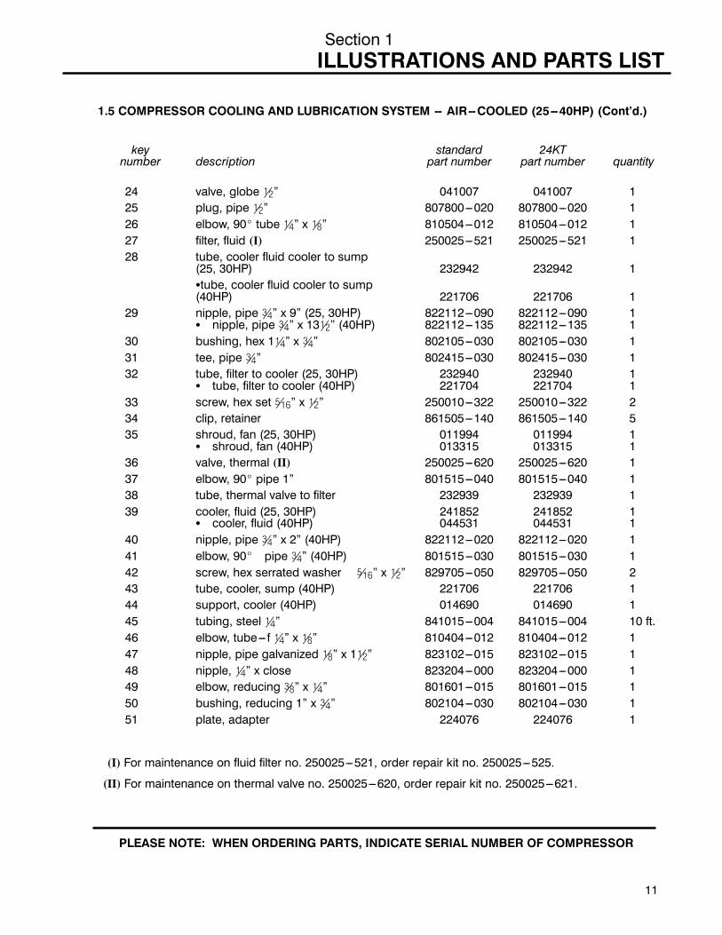
1.5 COMPRESSOR COOLING AND LUBRICATION SYSTEM -- AIR--COOLED (25--40HP) (Cont’d.)
key standard 24KTnumber description part number part number quantity
24 valve, globe !@2” 041007 041007 125 plug, pipe !@2” 807800---020 807800---020 126 elbow, 90_ tube !@4” x !@8” 810504---012 810504---012 127 filter, fluid (I) 250025---521 250025---521 128 tube, cooler fluid cooler to sump
(25, 30HP) 232942 232942 1Stube, cooler fluid cooler to sump(40HP) 221706 221706 1
29 nipple, pipe #@4” x 9” (25, 30HP) 822112---090 822112---090 1S nipple, pipe #@4” x 13!@2” (40HP) 822112---135 822112---135 1
30 bushing, hex 1!@4” x #@4” 802105---030 802105---030 131 tee, pipe #@4” 802415---030 802415---030 132 tube, filter to cooler (25, 30HP) 232940 232940 1
S tube, filter to cooler (40HP) 221704 221704 133 screw, hex set %@16” x !@2” 250010---322 250010---322 234 clip, retainer 861505---140 861505---140 535 shroud, fan (25, 30HP) 011994 011994 1
S shroud, fan (40HP) 013315 013315 136 valve, thermal (II) 250025---620 250025---620 137 elbow, 90_ pipe 1” 801515---040 801515---040 138 tube, thermal valve to filter 232939 232939 139 cooler, fluid (25, 30HP) 241852 241852 1
S cooler, fluid (40HP) 044531 044531 140 nipple, pipe #@4” x 2” (40HP) 822112---020 822112---020 141 elbow, 90_ pipe #@4” (40HP) 801515---030 801515---030 142 screw, hex serrated washer %@16” x !@2” 829705---050 829705---050 243 tube, cooler, sump (40HP) 221706 221706 144 support, cooler (40HP) 014690 014690 145 tubing, steel !@4” 841015---004 841015---004 10 ft.46 elbow, tube--- f !@4” x !@8” 810404---012 810404---012 147 nipple, pipe galvanized !@8” x 1!@2” 823102---015 823102---015 148 nipple, !@4” x close 823204---000 823204---000 149 elbow, reducing #@8” x !@4” 801601---015 801601---015 150 bushing, reducing 1” x #@4” 802104---030 802104---030 151 plate, adapter 224076 224076 1
(I) For maintenance on fluid filter no. 250025---521, order repair kit no. 250025---525.
(II) For maintenance on thermal valve no. 250025---620, order repair kit no. 250025---621.
PLEASE NOTE: WHEN ORDERING PARTS, INDICATE SERIAL NUMBER OF COMPRESSOR

Section 1ILLUSTRATIONS AND PARTS LIST
12
1.6 COMPRESSOR COOLING AND LUBRICATION SYSTEM -- WATER--COOLED (25 AND 30HP)

Section 1ILLUSTRATIONS AND PARTS LIST
13
1.6 COMPRESSOR COOLING AND LUBRICATION SYSTEM -- WATER--COOLED (25 AND 30HP)
key standard 24KTnumber description part number part number quantity
1 switch, pressure water 250017---992 250017---992 12 cover, motor shaft 012266 012266 13 nipple, pipe #@4” x 2!@2” 822112---025 822112---025 14 elbow, 45_ #@4” 801415---030 801415---030 15 elbow, 90_ tube #@4” x #@4” 810512---075 810512---075 36 tube, fluid stop 232823 232823 17 elbow, tube !@4” x !@8” 810504---012 810504---012 28 tubing, copper !@4” 840115---004 840115---004 5 ft.9 elbow, 90_ tube !@4” x !@4” 810504---025 810504---025 110 elbow, reducing 1” x #@4” 801604---030 801604---030 211 nipple, pipe 1” x 2!@2” 822216---025 822216---025 212 locknut, conduit !@2” 847200---050 847200---050 113 elbow, reducing 1!@4” x #@4” 801605---030 801605---030 114 filter, fluid (I) 250025---521 250025---521 115 bushing, hex 1!@4” x #@4” 802105---030 802105---030 116 connector, tube #@4” x #@4” 810212---075 810212---075 317 tube, filter/cooler 221703 221703 118 cooler, fluid 043096 043096 119 nut, hex ser washer plated %@16”---18 825305---283 825305---283 420 nipple, close #@4” 822212---000 822212---000 221 tee, reducing #@4” x !@2” x #@4” 802203---023 802203---023 122 nipple, close !@2” 822208---000 822208---000 123 valve, globe !@2” 041007 041007 124 plug, pipe !@2” 807800---020 807800---020 125 tube, cooler/sump 221705 221705 126 screw, hex ser washer %@16” x #@4” 829705---075 829705---075 427 screw, hex 8.8M10 x 75mm 828010---075 828010---075 228 tee, reducing 1” x !@2” x 1” 802204---024 802204---024 129 tie wrap, plastic 843200---025 843200---025 230 nipple, pipe 1” x 6” 822116---060 822116---060 131 bushing, hex !@2” x !@4” 802102---010 802102---010 132 tee, reducing #@4” x !@2” x !@2” 802203---022 802203---022 133 nipple, pipe !@2” x 1!@2” 822108---015 822108---015 234 union, pipe !@2” 802515---020 802515---020 135 valve, water regulator !@2” 041265 041265 136 nipple, pipe 1!@4” x 6” 822120---060 822120---060 1
(continued on Page 15)
(I) For maintenance on fluid filter no. 250025---521, order repair kit no. 250025---525.
PLEASE NOTE: WHEN ORDERING PARTS, INDICATE SERIAL NUMBER OF COMPRESSOR

Section 1ILLUSTRATIONS AND PARTS LIST
14
1.6 COMPRESSOR COOLING AND LUBRICATION SYSTEM -- WATER--COOLED (25 AND 30HP)

Section 1ILLUSTRATIONS AND PARTS LIST
15
1.6 COMPRESSOR COOLING AND LUBRICATION SYSTEM -- WATER--COOLED (25 AND 30HP)(Cont’d.)
key standard 24KTnumber description part number part number quantity
37 washer, flat #@8” 838206---071 838206---071 238 tube, steel #@4” 16 gauge 841115---012 841115---012 1!@2 ft39 nipple, !@8” x close 823202---000 823202---000 140 elbow, !@4” x !@8” FNPT 810404---012 810404---012 141 screw, %@16” x !@2” 829705---050 829705---050 2
PLEASE NOTE: WHEN ORDERING PARTS, INDICATE SERIAL NUMBER OF COMPRESSOR

Section 1ILLUSTRATIONS AND PARTS LIST
16
1.7 COMPRESSOR COOLING AND LUBRICATION SYSTEM -- WATER--COOLED (40HP)

Section 1ILLUSTRATIONS AND PARTS LIST
17
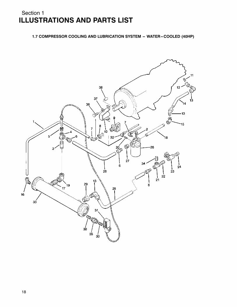
1.7 COMPRESSOR COOLING AND LUBRICATION SYSTEM -- WATER--COOLED (40HP)
key standard 24KTnumber description part number part number quantity
1 tubing, copper !@4” 840115---004 840115---004 6 ft.2 washer, plain b---regular #@8” 837206---071 837206---071 203 nipple, pipe 1” x 4” 822116---040 822116---040 14 tee, reducing 1” x #@4” x #@4” 802204---033 802204---033 15 bushing, hex #@4” x !@2” 802103---020 802103---020 16 connector, tube #@4” x #@4” 810212---075 810212---075 37 elbow, 90_ tube !@4” x !@8” 810504---012 810504---012 28 locknut, conduit !@2” 847200---050 847200---050 19 switch, water pressure 250017---992 250017---992 110 cover, motor shaft 014996 014996 111 nipple, pipe #@4” x 2!@2” 822112---025 822112---025 112 elbow, 45_ pipe #@4” 801415---030 801415---030 113 elbow, 90_ tube #@4” x #@4” 810512---075 810512---075 314 tube, fluid stop/unit 232823 232823 115 elbow, reducing 1!@4” x #@4” 801605---030 801605---030 116 elbow, 90_ tube !@4” x #@8” 810504---038 810504---038 117 nipple, close 1!@2” x close 822224---000 822224---000 118 nipple, pipe 1” x 6” 822120---060 822120---060 119 elbow, reducing 1!@2” x 1” 801606---040 801606---040 120 plate, support 227158 227158 121 tee, reducing #@4” x !@2” x #@4” 802203---023 802203---023 122 nipple, close !@2” 822208---000 822208---000 123 valve, globe !@2” 041007 041007 124 plug, pipe !@2” steel 807800---020 807800---020 125 tube, sump/oil cooler 227076 227076 126 filter, fluid (I) 250025---521 250025---525 127 bushing, reducing 1!@4” x #@4” 802105---030 802105---030 128 tube, oil cooler/filter 227074 227074 129 bushing, hex 1!@2” x #@4” 802106---030 802106---030 130 nipple, pipe #@4” x 3” 822112---030 822112---030 131 valve, water regulator #@4” 041266 041266 132 clamp, retaining 4!@2” 041983 041983 233 heat exchanger 4” x 24” 042657 042657 134 nipple, close #@4” 822212---000 822212---000 335 union, #@4” 802515---030 802515---030 136 screw, 8.8M10 x 75mm 828010---075 828010---075 2
(continued on Page 19)
(I) For maintenance on fluid filter no. 250025---521, order repair kit no. 250025---525.
PLEASE NOTE: WHEN ORDERING PARTS, INDICATE SERIAL NUMBER OF COMPRESSOR
Section 1ILLUSTRATIONS AND PARTS LIST
18
1.7 COMPRESSOR COOLING AND LUBRICATION SYSTEM -- WATER--COOLED (40HP)

Section 1ILLUSTRATIONS AND PARTS LIST
19
1.7 COMPRESSOR COOLING AND LUBRICATION SYSTEM -- WATER--COOLED (40HP) (Cont’d.)
key standard 24KTnumber description part number part number quantity
37 washer, flat #@8” 838206---071 838206---071 238 tube, steel #@4” 16 gauge 841115---012 841115---012 1!@2 ft39 screw, %@16” x !@2” 829705---050 829705---050 240 elbow, !@4” x !@8” FNPT 810404---012 810404---012 141 nipple, !@8” x close 823202---000 823202---000 1
PLEASE NOTE: WHEN ORDERING PARTS, INDICATE SERIAL NUMBER OF COMPRESSOR

Section 1ILLUSTRATIONS AND PARTS LIST
20
1.8 COMPRESSOR DISCHARGE SYSTEM

Section 1ILLUSTRATIONS AND PARTS LIST
21
1.8 COMPRESSOR DISCHARGE SYSTEM
key standard 24KTnumber description part number part number quantity
1 switch, pressure 10---250# spot open 250017---991 250017---991 12 locknut, conduit !@2” 847200---050 847200---050 23 valve, check !@4” (I) 049905 049905 14 connector, tube---m !@4” x !@8” 810204---012 810204---012 15 tubing, steel !@4” 20 gauge 841115---004 841115---004 6 ft.6 connector, !@2” 846400---050 846400---050 17 conduit, !@2” 846215---050 846215---050 38 elbow, 90_ conduit 846600---050 846600---050 19 coupling, conduit 250007---179 250007---179 110 probe, temperature (24KT) --- 046867 1
S probe, temperature (std.) 040588 --- 111 tee, reducing 1!@2” x !@2” x 1!@2” 802206---026 802206---026 112 nipple, close 1!@2” x close (25 & 30HP) 822224---000 822224---000 1
S nipple, close 1!@2” x 3” (40HP) 822124---030 822124---030 113 elbow, tube 90_ !@4” x !@8” 810504---012 810504---012 214 tee, tube !@4” x !@4” 810904---025 810904---025 115 tee, reducing !@2” x !@4” x !@2” 802202---012 802202---012 116 nipple, close !@2” 822208---000 822208---000 117 valve, pressure relief !@2” 250006---938 250006---938 118 connector, tube---m 1” x 1” 810216---100 810216---100 119 bushing, reducing hex 1!@4” x 1” 802105---040 802105---040 120 valve, minimum pressure (II) 241581 241581 121 connector, flex !@4” x !@4” 020169 020169 122 tube, return line 220700 220700 123 strainer, v--- type (III) 241771 241771 124 glass, oil sight 046559 046559 125 coupling, flexible (std.) (IV) 040033 --- 1
S coupling, flexible (24KT) (V) --- 250007---544 126 nipple, pipe 1!@4” x 2!@2” 822120---025 822120---025 127 capscrew, hex gr5 !@2”---13 x 1!@4” 828608---125 828608---125 828 washer, springlock !@2” 837508---125 837508---125 829 elbow, tube---m 90_ !@4” x !@4” 810504---025 810504---025 1
(continued on Page 23)
(I) For maintenance on check valve no. 049905, order replacement spring no. 250003---657.
(II) For maintenance on minimum pressure valve no. 241581, order seal kit no. 250026---758.
(III) For maintenance on v---type strainer no. 241771, order repair kit no. 241772.
(IV) For maintenance on flexible coupling no. 040033, order gasket kit no. 040517.
(V) For maintenance on flexible coupling no. 250007---544, order gasket kit no. 250007---559.
PLEASE NOTE: WHEN ORDERING PARTS, INDICATE SERIAL NUMBER OF COMPRESSOR

Section 1ILLUSTRATIONS AND PARTS LIST
22
1.8 COMPRESSOR DISCHARGE SYSTEM

Section 1ILLUSTRATIONS AND PARTS LIST
23
1.8 COMPRESSOR DISCHARGE SYSTEM (continued)
key standard 24KTnumber description part number part number quantity
30 nipple, half 1!@2” x 5!@2” 822824---055 822824---055 131 tank, sump 047070 047070 132 element, separator (25 & 30HP) (II) 250034---111 250034---113 1
S element, separator (40HP) (I) (II) 250034---111 250034---113 133 gauge, temperature 2” 042582 042582 134 cap, fluid fill 040029 040029 135 adapter, fill cap 020044 020044 136 tee, reducing 1” x 1” x 1!@2” 802204---046 802204---046 137 glass, sight 041327 041327 138 capscrew, hex head gr8 !@2”x1!@2”
(25,30HP) 828608---150 828608---150 2Scapscrew, !@2”---13 x 2!@4” (40HP) 828608---225 828608---225 2
39 nipple, close !@4” 6aw galv 823204---000 823204---000 240 washer, springlock !@2” 837508---125 837508---125 241 nut, hex !@2”---13 824208---448 824208---448 242 washer, !@2” flat 838208---112 838208---112 243 spacer (40HP) 232684 232684 129
(I) For maintenance on separator element (std.) no. 250034---111, order repair kitno. 250034---112.
(II) For maintenance on separator element (24KT) no. 250034---113, order repair kitno. 250034---114.
PLEASE NOTE: WHEN ORDERING PARTS, INDICATE SERIAL NUMBER OF COMPRESSOR

Section 1ILLUSTRATIONS AND PARTS LIST
24
1.9 ELECTRICAL BOX

Section 1ILLUSTRATIONS AND PARTS LIST
25
1.9 ELECTRICAL BOX
key standard 24KTnumber description part number part number quantity
1 gasket, motor/starter mount (25 & 30HP) 250030---147 250030---147 1S gasket, motor/starter mount (40HP) 405159 405159 1
2 washer, #10 external tooth 838402---025 838402---025 23 adaptor, motor (25 & 30HP) 250027---818 250027---818 1
S adaptor, motor (40HP) 250027---890 250027---890 14 gasket, starter 220790 220790 25 nut, hex %@16”---18 825305---283 825305---283 76 screw, %@16”---18 x #@4” (25, 30HP) 829705---075 829705---075 7
Sscrew, %@16”---18 x #@4” (40HP) 829705---075 829705---075 57 adapter, motor/starter (25, 30HP) 250021---278 250021---278 18 bar, 1” x 2” x 3” (40HP) 040632 040632 29 screw, serrated washer %@16”---18 x #@4”
(25, 30HP) 829705---075 829705---075 2Sscrew, serrated washer %@16”---18 x 1!@2”(40HP) 829705---150 829705---150 2
10 hourmeter, 2!@2” 120V 60Hz 042988 042988 111 gasket, hourmeter 410353 410353 112 nameplate, START 250023---049 250023---049 113 pushbutton, START assembly 250016---351 250016---351 114 nameplate, STOP 250023---050 250023---050 115 pushbutton, STOP assembly 250016---350 250016---350 116 lug, scrulug 4 str 1/0 str %@16” 849215---025 849215---025 117 wrap, tie plastic 26m !@16” x 1#@4” 843200---025 843200---025 218 starter, N3 open 052362 052362 1
S starter, N4 open 052036 052036 119 transformer, 380/416V 250028---878 250028---878 1
S transformer, 208V 250028---872 250028---872 1S transformer, 230/460V 250028---721 250028---721 1S transformer, 600V 250028---884 250028---884 1
20 plug, hole !@2” 045689 045689 221 clip, plastic 041632 041632 222 control, temperature (KT only) --- 409270 123 screw, #@8” x 16 x #@4” (25, 30HP) 828606---075 828606---075 424 washer, #@8” springlock (25, 30HP) 837506---094 837506---094 425 washer, %@16” external tooth 838405---034 838405---034 626 track, snap mounting 250024---522 250024---522 127 screw, 8---32 x !@2” 835601---050 635601---050 2
PLEASE NOTE: WHEN ORDERING PARTS, INDICATE SERIAL NUMBER OF COMPRESSOR
Section 1ILLUSTRATIONS AND PARTS LIST
26
1.10 PNEUMATIC CONTROLS

Section 1ILLUSTRATIONS AND PARTS LIST
27
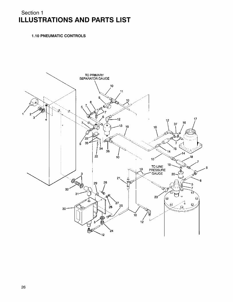
1.10 PNEUMATIC CONTROLS
key standard 24KTnumber description part number part number quantity
1 valve, solenoid !@4” 3---way (I) 250017---993 250017---993 12 bushing, conduit plastic !@2” 848815---050 848815---050 13 locknut, conduit !@2” 847200---050 847200---050 44 nut, hex serrated washer %@16” 825305---283 825305---283 25 elbow, pipe 90_ !@4” 803515---010 803515---010 46 nipple, pipe !@4” x 4!@2” 823104---045 823104---045 17 nipple, pipe !@4” x close 823204---000 823204---000 88 tee, pipe !@4” 804415---010 804415---010 19 strainer, v--- type (II) 241771 241771 110 tubing, steel !@4” 841015---004 841015---004 6 ft.11 tee, tube---m !@4” x !@4” x !@4” 810804---025 810804---025 112 elbow, tube---m !@4” x !@4” 810504---025 810504---025 313 valve, pressure regulator (III) 250017---280 250017---280 114 connector, tube---m !@4” x !@4” 810204---025 810204---025 215 valve, check !@4” 049905 049905 116 orifice, pipe plug !@4” 232874 232874 117 valve, air inlet 2!@2” (IV) 250025---654 250025---654 118 valve, blowdown !@4” (V) 250025---655 250025---655 119 bushing, reducing !@4” x !@8” 807600---005 807600---005 120 silencer, !@8” 043196 043196 121 tee, tube union !@4” 811404---025 811404---025 122 screw, 8---32 x #@8” 835601---038 835601---038 223 elbow, tube---m !@4” x !@8” 810504---012 810504---012 124 nipple, chase conduit !@2” 847815---050 847815---050 125 screw, 10---32 x !@2” 831702---050 831702---050 226 washer, springlock #10 838502---047 838502---047 227 nut, 10---32 825801---130 825801---130 228 screw, hex serrated washer %@16” x #@4” 829705---075 829705---075 229 bracket, pressure switch 250018---146 250018---146 130 switch, pressure 040694 040694 1
(continued on Page 29)
(I) For maintenance on solenoid valve no. 250017---993, order repair kit no. 250018---970.
(II) For maintenance on v---type strainer no. 241771, order repair kit no. 241772.
(III) For maintenance on pressure regulator valve no. 250017---280, order repair kit no. 250019---453.
(IV) For maintenance on air inlet valve no. 250025---654, order repair kit no. 250019---451.
(V) For maintenance on blowdown valve no. 250025---655, order repair kit no. 250031---772.
PLEASE NOTE: WHEN ORDERING PARTS, INDICATE SERIAL NUMBER OF COMPRESSOR

Section 1ILLUSTRATIONS AND PARTS LIST
28
1.10 PNEUMATIC CONTROLS

Section 1ILLUSTRATIONS AND PARTS LIST
29
1.10 PNEUMATIC CONTROLS (continued)
key standard 24KTnumber description part number part number quantity
31 elbow, corner pull 90_ !@2” 846915---050 846915---050 132 nipple, conduit !@2” x !@2” 250007---169 250007---169 333 bracket, solenoid valve support 250030---037 250030---037 134 screw, tc--- f pan #10---24 x !@2” 835602---050 835602---050 235 washer, loc ext #10 838402---025 838402---025 436 tee, tube m---run !@4” x !@4” 810904---025 810904---025 137 pipe, cross !@4” 803315---010 803315---010 1
PLEASE NOTE: WHEN ORDERING PARTS, INDICATE SERIAL NUMBER OF COMPRESSOR

Section 1ILLUSTRATIONS AND PARTS LIST
30
1.11 INSTRUMENT PANEL -- OPEN AND ENCLOSURE OPTION

Section 1ILLUSTRATIONS AND PARTS LIST
31
1.11 INSTRUMENT PANEL -- OPEN AND ENCLOSURE OPTION
key standard 24KTnumber description part number part number quantity
1 gauge, temperature 042582 042582 12 gauge, air pressure 250005---185 250005---185 23 gauge, separator maintenance 250003---798 250003---798 14 gauge, fluid filter maintenance 250003---799 250003---799 15 panel, instrument (open) 250003---873 250003---873 16 connector, tube--- f !@4” x !@8” 810104---012 810104---012 57 tee, tube--- f run !@4” x !@8” 811004---012 811004---012 18 nut, hex serrated washer plated %@16”---18 825305---283 825305---283 29 screw, hex serrated washer %@16” x #@4” 829705---075 829705---075 210 tubing, steel !@4” 840115---004 840115---004 1011 label, instrument panel 250004---977 250004---977 1
PLEASE NOTE: WHEN ORDERING PARTS, INDICATE SERIAL NUMBER OF COMPRESSOR

Section 1ILLUSTRATIONS AND PARTS LIST
32
1.12 AIR--COOLED AFTERCOOLING OPTION (25 AND 30HP)

Section 1ILLUSTRATIONS AND PARTS LIST
33
1.12 AIR--COOLED AFTERCOOLING OPTION (25 AND 30HP)
key standard 24KTnumber description part number part number quantity
1 screw, hex head ser wash %@16” x #@4” 829705---075 829705---075 62 panel, cooler adapter 224076 224076 13 nut, retainer “J” %@16”---18 861405---092 861405---092 44 nut, hex serrated wash plated %@16”---18 825305---283 825305---283 25 elbow, 1” x #@4” mnpt (25, 30HP) 810516---075 810516---075 2
Selbow, 90_ tube 1” x 1” (40HP) 810516---100 810516---100 26 tube, aftercooler/check valve (25, 30HP) 221700 221700 1
S tube, aftercooler/check valve (40HP) 250026---954 250026---954 17 connector, tube 1” x 1” 810216---100 810216---100 28 bushing, hex 1!@4” x 1” 802105---040 802105---040 19 bushing, hex 2” x 1” 802108---040 802108---040 110 separator/trap (I) 040847 040847 111 elbow, reducing 2” x 1!@2” 801608---060 801608---060 112 bracket, mount trap 021481 021481 113 washer, springlock regular !@2” 837508---125 837508---125 214 nut, hex !@2”---13 824208---448 824208---448 215 capscrew, hex head gr5 !@2” x 1!@2” 828608---150 828608---150 216 tube, aftercooler/separator (25, 30HP) 232968 232968 1
S tube, aftercooler/separator (40HP) 250026---955 250026---955 117 aftercooler, (25, 30HP) 407106 407106 1
S aftercooler, (40HP) 241852 241852 1
(I) For maintenance on separator/trap no. 040847, order repair kit no. 044374.
PLEASE NOTE: WHEN ORDERING PARTS, INDICATE SERIAL NUMBER OF COMPRESSOR

Section 1ILLUSTRATIONS AND PARTS LIST
34
1.13 WATER--COOLED AFTERCOOLING OPTION (25 AND 30HP)

Section 1ILLUSTRATIONS AND PARTS LIST
35
1.13 WATER--COOLED AFTERCOOLING OPTION (25 AND 30HP)
key standard 24KTnumber description part number part number quantity
1 bracket, mount trap 021481 021481 12 separator/trap (I) 040847 040847 13 heat exchanger 043096 043096 14 tube, aftercooler/oil cooler 221699 221699 15 tube, aftercooler/separator 250026---956 250026---956 16 tube, MPV/aftercooler 232829 232829 17 elbow, 90_ pipe 1” 801515---040 801515---040 18 elbow, reducing 2” x 1!@2” 801608---060 801608---060 19 bushing, hex 1!@4” x 1” 802105---040 802105---040 110 bushing, hex 2” x 1” 802108---040 802108---040 111 connector, tube %@8” x !@2” 810210---050 810210---050 212 connector, tube 1” x 1” 810216---100 810216---100 313 elbow, 90_ tube 1” x 1” 810516---100 810516---100 114 nipple, pipe 1” x 5” 822116---050 822116---050 115 nut, hex !@2”---13 824208---448 824208---448 216 nut, hex serrated washer %@16”---18 825305---283 825305---283 417 capscrew, hex gr5 !@2” x 1!@2” 828608---150 828608---150 218 screw, hex serrated washer %@16” x #@4” 829705---075 829705---075 419 washer, springlock regular !@2” 837508---125 837508---125 220 cap, inlet---outlet 044244 044244 121 cap, reversing 044245 044245 122 gasket, inlet---outlet 044242 044242 123 gasket, reversing cap 044243 044243 124 bushing, reducing #@4” x !@2” 802103---020 802103---020 2
(I) For maintenance on separator/trap no. 040847, order repair kit no. 043374.
PLEASE NOTE: WHEN ORDERING PARTS, INDICATE SERIAL NUMBER OF COMPRESSOR

Section 1ILLUSTRATIONS AND PARTS LIST
36
1.14 WATER--COOLED AFTERCOOLING OPTION (40HP)

Section 1ILLUSTRATIONS AND PARTS LIST
37
1.14 WATER--COOLED AFTERCOOLING OPTION (40HP)
key standard 24KTnumber description part number part number quantity
1 washer, flat #@8” 838206---071 838206---071 42 tube, MPV/aftercooler 227075 227075 13 connector, tube 1” x1” 810216---100 810216---100 34 bushing, hex 1!@4” x 1” 802105---040 802105---040 15 bushing, hex 1!@2” x 1” 802106---040 802106---040 26 bushing, hex 1” x #@4” 802104---030 802104---030 17 connector, tube #@4” x #@4” 810212---075 810212---075 18 tube, separator/aftercooler 227077 227077 19 bushing, hex 2” x 1” 802108---040 802108---040 110 separator/trap (I) 040847 040847 1
S heater (optional) 245572 245572 111 elbow, reducing 2” x 1!@2” 801608---060 801608---060 112 bracket, mount trap 021481 021481 113 washer, springlock regular !@2” 837508---125 837508---125 414 nut, hex !@2”---13 824208---448 824208---448 215 capscrew, hex head gr5 !@2” x 1!@2” 828608---150 828608---150 216 tube, aftercooler/oil cooler 227078 227078 117 elbow, #@4” x #@4” mnpt 810212---075 810212---075 118 nut, %@16”---18 825305---283 825305---283 419 gasket, reversing cap 044221 044221 120 heat exchanger 043062 043062 121 elbow, tube 1” x 1” 810516---100 810516---100 122 cap, inlet---outlet 044229 044229 123 cap, reversing 044228 044228 124 gasket, inlet---outlet cap 044220 044220 125 screw, %@16” x #@4” 829705---075 829705---075 4
(I) For maintenance on separator/trap no. 040847, order repair kit no. 044374.
PLEASE NOTE: WHEN ORDERING PARTS, INDICATE SERIAL NUMBER OF COMPRESSOR

Section 1ILLUSTRATIONS AND PARTS LIST
38
1.15 WATER--COOLED AND AIR--COOLED ENCLOSURE AND PARTS -- OPTION

Section 1ILLUSTRATIONS AND PARTS LIST
39
1.15 WATER--COOLED AND AIR--COOLED ENCLOSURE AND PARTS -- OPTION
key standard 24KTnumber description part number part number quantity
1 panel, roof 250018---316 250018---316 22 panel, fiberglass 5” x 35!@2” 049889---035 049889---035 43 grill, cooler (air---cooled) 242095 242095 14 nut, retainer “J” %@16”---18 u---clip 861505---140 861505---140 145 screw, hex serrated washer %@16” x #@4”
(air---cooled) 829705---075 829705---075 40S screw, hex serrated washer %@16” x #@4”(water---cooled) 829705---075 829705---075 36
6 panel, access 014620 014620 27 panel, fiberglass 15!@4” x 32!@2”
(air---cooled) 049889---005 049889---005 6S panel, fiberglass 15!@4” x 32!@2”(water---cooled) 049889---005 049889---005 7
8 weatherstrip, felt 043502 043502 75 ft.9 panel, enclosure center 224585 224585 310 guard, fan 13” 241579 241579 111 washer, springlock regular !@4” (AC) 837504---062 837504---062 6
Swasher, springlock regular !@4” (WC) 837504---062 837504---062 1212 capscrew, hex head gr5 !@4”---20 x 1”
(air---cooled) 829104---100 829104---100 6S capscrew, hex head gr5 !@4”---20 x 1”(water---cooled) 829104---100 829104---100 12
13 panel, end 02250043---677 02250043---677 114 fan, enclosure 241580 241580 115 nut, hex !@4”---20 824204---226 824204---226 416 rivet, tubular !@4”---20 049824 049824 817 nut, hex !@2”---13 824208---448 824208---448 418 panel, fiberglass 13” x 36!@2” 049889---012 049889---012 419 panel, enclosure --- right hand 224583 224583 220 nut, hex serrated washer pltd %@16”---18
(air---cooled) 825305---283 825305---283 28nut, hex serrated washer pltd %@16”---18(water---cooled) 825305---283 825305---283 24
21 panel, enclosure --- left hand 224584 224584 222 frame, enclosure 014790 014790 123 panel, cooler end (air---cooled) 014812 014812 124 clamp, speed !@4” (air---cooled) 043194 043194 425 latch, door (air---cooled) 049764 049764 3
latch, door (water---cooled) 049764 049764 526 panel, access 250018---708 250018---708 127 panel, enclosure front 250003---872 250003---872 128 capscrew, hex head gr5 !@2” x 1!@2” 828608---150 828608---150 429 washer, springlock regular !@2” 837508---125 837508---125 430 nut, retainer (air---cooled) 861405---092 861405---092 4
PLEASE NOTE: WHEN ORDERING PARTS, INDICATE SERIAL NUMBER OF COMPRESSOR

Section 1ILLUSTRATIONS AND PARTS LIST
40
1.16 HEAVY DUTY FILTER OPTION

Section 1ILLUSTRATIONS AND PARTS LIST
41
1.16 HEAVY DUTY FILTER OPTION
key standard 24KTnumber description part number part number quantity
1 nipple, close 2!@2” 822240---000 822240---000 12 elbow, reducing 2!@2” x 2” (25, 30HP) 801610---080 801610---080 1
S elbow, pipe 90_ 2!@2” (40HP) 801515---100 801515---100 13 nipple, half 2” x 3” (25, 30HP) 822832---030 822832---030 1
S nipple half 2!@2” x 3” (40HP) 822840---030 822840---030 14 clamp, hose 1&@8” x 2#@4” (25, 30HP) 040083 040083 2
S clamp, hose 3” (40HP) 040343 040343 25 elbow, rubber (25, 30HP) 044634 044634 1
S elbow, rubber (40HP) 041960 041960 16 indicator, air filter maintenance 045757 045757 17 support, air filter (25, 30HP) 250042---848 250042---848 1
S bracket, air filter (40HP) 015718 015718 18 filter, air (25, 30HP) (I) 043333 043333 1
S filter, air (40HP) (II) 040595 040595 19 screw, hex serrated washer %@16” x #@4” 829705---075 829705---075 210 band, mounting (25, 30HP) 043370 043370 1
S band, mounting (40 HP) 040598 040598 111 nut, hex serrated washer plated %@16”---16 825305---283 825305---283 212 capscrew, hex head gr5 #@8” x 1!@4”
(25, 30HP) 828606---125 828606---125 213 washer, springlock regular #@8”
(25, 30 HP) 837506---094 837506---094 214 nut, hex #@8”---16 (25, 30HP) 824206---337 824206---337 2
(I) For maintenance on air filter no. 043333, order replacement element no. 043334.
(II) For maintenance on air filter no. 040595, order replacement element no. 040596.
PLEASE NOTE: WHEN ORDERING PARTS, INDICATE SERIAL NUMBER OF COMPRESSOR

Section 1ILLUSTRATIONS AND PARTS LIST
42
1.17 OPTIONAL AIR TANK -- 120 AND 200 GALLON

Section 1ILLUSTRATIONS AND PARTS LIST
43
1.17 OPTIONAL AIR TANK -- 120 AND 200 GALLON
key standard 24KTnumber description part number part number quantity
1 tank, receiver (120 gallon) 042878 042878 1tank, receiver (200 gallon) 042877 042877 1
2 nipple, pipe 1!@4” x close 822220---000 822220---000 13 tee, side outlet 1!@4” 802715---050 802715---050 14 bushing, hex 1!@4” x !@2” 802105---020 802105---020 15 valve, pressure relief 043041 043041 16 bushing, hex 1!@4” x !@4” 802105---010 802105---010 17 nipple, close !@4” 823204---000 823204---000 18 gauge, pressure 040691 040691 19 elbow, pipe !@4” 90_ 803515---010 803515---010 110 tee, pipe #@4” 802415---030 802415---030 111 bushing, hex #@4” x #@8” 802103---015 802103---015 112 bushing, hex 1!@4” x 1” 802105---040 802105---040 213 elbow, pipe #@4” 45_ 801415---030 801415---030 114 trap, automatic #@4” 042034 042034 115 nipple, close #@8” xs 822206---000 822206---000 116 plug, pipe 1!@4” 802815---050 802815---050 417 nipple, close #@4” 822212---000 822212---000 318 elbow, pipe #@4” 801515---030 801515---030 119 nipple, pipe #@4” x 8” 822112---080 822112---080 120 valve, globe 042733 042733 121 plug, pipe #@8” 807800---015 807800---015 1
(ALL NON--AFTER COOLED COMPRESSORS)22 hose, assembly 1” x 40”
(25/30/40HP ac and wc) 248369 248369 123 elbow, 37_ flare 90_m #@4” x 1”
(25/30HP ac) 860216---075 860216---075 1elbow, 37_ flare 90_m 1” x 1”(25/30HP wc and 40HP ac) 860216---100 860216---100 1
PLEASE NOTE: WHEN ORDERING PARTS, INDICATE SERIAL NUMBER OF COMPRESSOR

Section 1ILLUSTRATIONS AND PARTS LIST
44
1.18 DECAL GROUP
1
2 34
5
6
7
8
9
10

Section 1ILLUSTRATIONS AND PARTS LIST
45
1.18 DECAL GROUP
key standard 24KTnumber description part number part number quantity
1 decal, airanteed 2 year ---white 043067 043067 12 sign, warning sever fan 049855 049855 23 sign, warning sever fan port 049965 049965 14 sign, danger electrocution 049850 049850 15 decal, rotation 250021---286 250021---286 16 decal, 460 volt 040631 040631 17 decal, grounding lug 045433 045433 18 decal, compressor fluid Sullube---32 250023---361 250023---361 19 decal, SRF 1/4000 fluid 250022---839 250022---839 110 decal, 10---B---40HP maintenance kit 250034---136 250034---136 1
(Continued on Page 47)
PLEASE NOTE: WHEN ORDERING PARTS, INDICATE SERIAL NUMBER OF COMPRESSOR

Section 1ILLUSTRATIONS AND PARTS LIST
46
1.18 DECAL GROUP
1112
1314
15
16
1718
2019

Section 1ILLUSTRATIONS AND PARTS LIST
47
1.18 DECAL GROUP (Continued)
key standard 24KTnumber description part number part number quantity
11 sign, warning compressor oil fill cap 049685 049685 112 sign, danger air breathing 250027---935 250027---935 113 sign, warning “food grade” lube 250003---144 250003---144 114 sign, warning ground fault 049852 049852 115 decal, danger high voltage 042218 042218 116 decal, water inlet/outlet 049873 049873 117 decal, water in 250019---107 250019---107 118 decal, water out 250019---108 250019---108 119 decal, rotation 250021---564 250021---564 120 decal, water drain 250022---810 250022---810 121 decal, Sullair 16#@4” --- white (not shown) 250014---057 250014---057 122 decal, logo --- white (not shown) 040087A 040087A 1
PLEASE NOTE: WHEN ORDERING PARTS, INDICATE SERIAL NUMBER OF COMPRESSOR

NOTES

NOTES

Printed in U.S.A.
Specifications Subject ToChange Without Prior Notice
WORLDWIDE SALES AND SERVICE
SULLAIR CORPORATION
3700 E. Michigan Blvd. Michigan City, Indiana 46360---9990Telephone (219) 879---5451
A SUBSIDIARY OF SUNDSTRAND CORPORATION
R