Embed Size (px)
Citation preview

1
Industrial Case Study of ElectronicDesign, Cost and Schedule Integration
Sheryl Staub1, Martin Fischer2 and Melody Spradlin3
1Project Engineer, Hathaway/Dinwiddie Construction GroupSanta Clara, CA 95054-2419, USA
Graduate Research Assistant, Dept. of Civil & Env. Eng.,Stanford University, Stanford, CA 94305-4020, USA
2 Assistant Professor, Dept. of Civil & Env. Eng.,Stanford University, Stanford, CA 94305-4020, USA
3Project Manager, Hathaway/Dinwiddie Construction GroupSanta Clara, CA 95054-2419, USA
ABSTRACT
Even though most documents are generated electronically, today’s project management processes arestill characterized by a largely manual exchange of information based on paper documents. Projectteams could benefit from software technology that has been developed to integrate design, cost, andschedule information. Some of these benefits include the automatic generation of quantity take-offsdirectly from design drawings, improved visualization of construction schedules, improvedcoordination of construction disciplines, and improved communication between design andconstruction. This technology has existed for some time and research has shown that it is technicallyfeasible. However, we are not aware of a project team that has accomplished design, cost andschedule integration in a collaborative environment on an actual construction project. The SequusPharmaceuticals Pilot Plant is a project where a project team has implemented design, cost, andschedule integration and it forms the basis of our case study. On this bio-tech facility, a design-buildteam consisting of a design firm, a General Contractor, and three subcontractors has jointly developeda common 3D model from the very start of the project to link with cost estimating and schedulingsoftware. The electronic integration of design and cost information was accomplished through theCAD-estimate link developed by Ketiv and Timberline. Design and schedule integration (4D, 3D +time) was accomplished through Jacobus Technology's Schedule Simulator. This case has providedus the opportunity to investigate the status of commercial design, cost and schedule integrationsoftware and to understand the resource requirements necessary to accomplish these tasks on an actualproject. This study suggests that owners, designers and builders of facilities will need to develop newskills and implement organizational changes to take advantage of the benefits offered by thistechnology and to stay competitive in this changing market. Specifically, general contractors will needto learn how to manipulate 3D CAD models, work more closely with the designers in designdevelopment, and provide input on how to model designs in 3D so that the CAD models are moreusable by constructors. Subcontractors will also need to learn design software, as they will beperforming more detailed design, working more closely with the architects and engineers through thedesign process, and addressing coordination issues early in design development. Designers will needto focus more on the overall design and coordination of design tasks and less on detailed design.Finally, owners will need to bring a project team together early in the project to capitalize on thebenefits of this technology.
2
INTRODUCTION
Current estimating and planning processes are limited by the lack of integration between electronicdesign and construction information. A significant part of the estimating process involves thecalculation of quantities, which is currently performed manually by scaling off two-dimensional paperdrawings. But why do estimators perform this task manually when this information already exists andis available in the electronic design drawings? Additionally, construction schedules are created toshow the sequence for how construction operations are to proceed. Yet how can constructionschedules convey this message when commonly used scheduling tools don’t represent designinformation and the associated spatial requirements explicitly? Integration of design, cost andschedule information is necessary to improve the estimating and planning processes and to reduce theinefficiencies that result from the current fragmentation between design and construction information.
New software technologies have been developed that will help project teams to integrate design, costand schedule information. Such integration will allow construction professionals to automate quantitytakeoffs, thus shortening estimating time and eliminating the duplication of effort that exists in currentestimating practices. Integrating design and schedule information (4D CAD, 3D plus time) allowsproject teams to visualize the construction process and virtually build a proposed facility on thecomputer screen [Cleveland 1989, Collier and Fischer 1996, Williams 1996]. This 4D animationhelps a project team to evaluate the constructability of a proposed construction sequence prior toconstruction, communicate the intent of the construction schedule, and coordinate sub-trades. Thesoftware described has existed for some time. Several firms are using parts of this software internally,and many people have speculated about its benefit to project teams [Nevins et al 1991, Teicholz andFischer 1994, Wickard et al 1989]. We are not aware of a project where multiple firms havecollaborated using an integrated suite of project management software. We have used such softwarefor design and construction planning for the Pilot Plant for Sequus Pharmaceuticals, located in MenloPark, California.
At the start of this project, a project team was created with the explicit goal of using existing softwareto perform design, cost and schedule integration throughout all phases of project development. Theproject team consisted of the following companies: the design firm Flad & Associates, the GeneralContractor Hathaway/Dinwiddie Construction Group (Hathaway), the plumbing subcontractorRountree Plumbing, the HVAC subcontractor Paragon Mechanical, and the electrical subcontractorRosendin Electric. This project team jointly developed a common 3D model from the very start of theproject to link with cost estimating and scheduling software. The integration of design and costinformation was accomplished through the CAD-estimate link developed by Ketiv and Timberline.Design and schedule integration (4D, 3D + time) was accomplished through Jacobus Technology'sSchedule Simulator.
In this paper, we describe the efforts of the project team to perform design, cost and scheduleintegration on the Sequus Pharmaceuticals Pilot Plant. Specifically, we will discuss the following:
• the software used and how it functions,• the steps required to integrate electronic design, cost and schedule information,• the benefits and shortcomings of the software,• the changing roles of each discipline.
3
We will start by describing the current methods engineers and construction professionals use togenerate estimates and schedule sequences illustrating the inefficiencies that are created by the lack ofintegration between design and construction information.
CURRENT PRACTICES
Creating and Using EstimatesCurrently, there is a tremendous amount of effort required to transfer and interpret design information.Designers generate hundreds of pages of design drawings and several books of specifications for thecontractors to analyze, estimate and schedule. However, the current method of transferringinformation requires general contractors and subcontractors to calculate quantities manually.Information that designers put into the drawings cannot be reused directly because the informationtransmitted from designers to estimators is not in a usable, electronic form. Calculating quantities is acritical part of the estimating and planning processes, as it effects material and labor costs, and activitydurations. Yet the contractors do not have electronic access to this design information, giving rise toinefficiencies in the estimating process that increase estimating time and decrease accuracy. Design-cost integration software takes advantage of existing electronic design information, and provides theopportunity for contractors to automate part of the estimating process, to validate the completeness oftheir estimates, and to evaluate the cost impact of different design options quickly.
Creating and Using SchedulesA major task for construction planners is to determine the sequence of construction activities sothat resources are allocated appropriately and coordination of sub-trades is optimized. Currentproject management practice uses CPM (Critical Path Method) schedules to represent thecompletion of a facility design over time. CPM schedules show the dependencies betweenactivities, but they do not provide a link between the three dimensions of space and the forthdimension of time. Yet the interdependency between this information is critical for evaluating,monitoring, and coordinating the construction process. To improve coordination, generalcontractors often use architectural design drawings and overlay the different sub-trades' designsto coordinate the spatial needs of each discipline. While it brings the disciplines’ designperspectives together, this approach still abstracts the 3rd spatial dimension and the timedimension of construction work. 4D-CAD (3D + time) is a tool that allows constructors to linkdesign and sequencing information explicitly and to evaluate the spatial needs of each disciplineover time, thus improving communication and coordination between sub-trades.
In the next section, we will discuss the Sequus Project and the process by which information wastransferred between members of the project team.
THE SEQUUS PROJECT
Sequus Pharmaceuticals is a biopharmaceutical company located in Menlo Park, California. In1997, management started exploring options to expand the company and build a Pilot Plant onsite in Menlo Park. The Pilot Plant was to be constructed in an existing unoccupied warehouse

4
adjacent to their office building. The available space was 20,000 square feet, which was going tobe broken down into office space, manufacturing space, process development space, and futureexpansion space. The final design has 3,440 square feet of office space, 3,100 square feet ofmanufacturing space, 2,900 square feet of process development space, and 4,800 square feet offuture expansion space. The manufacturing space is made up of two compounding labs, adecontamination lab, buffer preparation with a weight room and air lock, and support areas. Theprocess development area is made up of two process development labs, a decontamination lab,gowning areas, and support areas. Figure 1 shows the 2D view of the 3D architectural modeldeveloped by Flad & Associates.
The general contractor assembled a design-build team based on each company’s experience withusing 3D CAD technology on past construction projects and the team’s experience in working witheach other. A common goal for each member of the project team was to explore the use of existingsoftware to integrate CAD technology with cost and scheduling software. Figure 2 shows thesoftware that will be utilized to perform design, cost and schedule integration.
Figure 1: Architectural Layout of Sequus Project
AutoCAD(Autodesk)
Schedule Simulator(Jacobus Technology)
Multi-Pipe(UHP Process
Piping)
Archt(Ketiv)
PrecisionEstimating
(Timberline)
Project(Microsoft)
Figure 2: Software Used to Perform Design, Cost and Schedule Integration

5
This was the first time that each member of the project team built a 3D CAD model in a collaborativeenvironment. As such, it required a completely new way to transfer information among the differentdisciplines. Figure 3 shows how the design information was transferred and shared between thedifferent disciplines on the Sequus Project.
Designing in a collaborative environment and utilizing design, cost and schedule integration softwareforced the project team to work together from the very start of design and to share informationthroughout all phases of design development. The general contractor was the party responsible fororchestrating and monitoring this process. The implications of this process will be discussed in latersections of this paper.
In the next section, we will discuss the steps required to perform software-based design-cost anddesign-schedule integration.
DESIGN-COST INTEGRATION
Process DescriptionTo perform design-cost integration, we linked estimating items and work packages from Timberline'sPrecision Estimating database with graphical objects created using AutoCAD R13 and Ketiv's ArchtArchitectural Drawing software package. Figure 4 shows an overview of this process: work packagesare attached to the CAD Model, quantity takeoffs are calculated from within the CAD environmentafter all the work packages have been attached to CAD design elements, and estimating items are thenrevised if necessary. This process is repeated until the user is satisfied with the results.
Flad &Associates
HathawayConstruction
RosendinElectric
ParagonMechanical
RountreePlumbing
HathawayConstruction
Designer G.C.
Subs
G.C.
Figure 3: The Transfer of Design Information on the Sequus Project

6
Process DetailsIn Precision Estimating, the user initially performs setup procedures which structure the estimatingitems and work packages so that they can be linked with the appropriate CAD dimension. The link iscreated by matching "Precision variables" with "AutoCAD variables". Precision variables reside inthe item or work package formula and define the unit of measure that will be used in the unit costcalculation, such as wall length or area. CAD variables are the dimensions of the graphical objects,such as length and thickness. To perform this link successfully, the user must have an understandingof the CAD Model and how the graphical objects have been drawn so that the correct CAD variablesare selected. The table below shows the most commonly used CAD objects and the associateddimensions that can be extracted:
Table 1: Supported CAD Dimension TypesCAD Object CAD Dimension Extracted
3D Solid VolumeCircle, or Closed Polyline Area of object, Diameter of circlePolyline with Thickness ThicknessLine Length
In addition, Ketiv objects include XDATA that can also be extracted through the Precision link, suchas “Wall Height” and “Wall Length”.
Figure 4: Overview of Design-Cost Integration
7
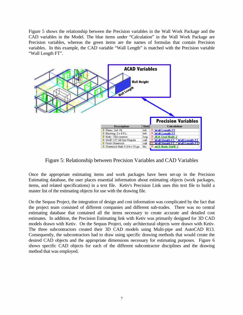
Figure 5 shows the relationship between the Precision variables in the Wall Work Package and theCAD variables in the Model. The blue items under “Calculation” in the Wall Work Package arePrecision variables, whereas the green items are the names of formulas that contain Precisionvariables. In this example, the CAD variable “Wall Length” is matched with the Precision variable“Wall Length FT”.
Once the appropriate estimating items and work packages have been set-up in the PrecisionEstimating database, the user places essential information about estimating objects (work packages,items, and related specifications) in a text file. Ketiv's Precision Link uses this text file to build amaster list of the estimating objects for use with the drawing file.
On the Sequus Project, the integration of design and cost information was complicated by the fact thatthe project team consisted of different companies and different sub-trades. There was no centralestimating database that contained all the items necessary to create accurate and detailed costestimates. In addition, the Precision Estimating link with Ketiv was primarily designed for 3D CADmodels drawn with Ketiv. On the Sequus Project, only architectural objects were drawn with Ketiv.The three subcontractors created their 3D CAD models using Multi-pipe and AutoCAD R13.Consequently, the subcontractors had to draw using specific drawing methods that would create thedesired CAD objects and the appropriate dimensions necessary for estimating purposes. Figure 6shows specific CAD objects for each of the different subcontractor disciplines and the drawingmethod that was employed.
Figure 5: Relationship between Precision Variables and CAD Variables

8
Five steps detail the effort required to perform design-cost integration on the Sequus PharmaceuticalsPilot Plant:
1. Add items to general contractor's estimating database for all the disciplines, including crewproduction rates whenever possible. To capitalize on the benefits of design-cost integration, it wasimportant to have detailed cost information for all the disciplines. The average duration to createthis database was three hours for each subcontractor. The estimating item detail varied dependingon the breakdown of work for each subcontractor. For example, the HVAC subcontractor oftenadded labor, fabrication and material costs, while the general contractor added items with unitcosts. A total of 314 items were added to the estimating database, with a breakdown bysubcontractor as follows: HVAC – 80 items, Piping – 183 items, Electrical – 30 items, andGeneral Contractor – 21 items.
2. Add formulas to estimating items added in step 1. This part is critical because the Precisionvariables identified in the formula will be linked with the CAD variables when the estimate iscreated. The total duration to complete this task was 12 hours.
Figure 6: CAD Objects and Associated Drawing Methods

9
3. Create work packages and item tables by grouping items created in step 1. The total duration tocomplete this task was 12 hours.
4. Attach work packages and items to each CAD Model. The Architectural Model contains 117entities, the HVAC Model contains 185 entities, the Electrical Model contains 1,564 entities, andthe Piping Model contained 3,139 entities. The amount of time necessary to attach work packagesand items to each model depended completely on the complexity of the 3D CAD model. Forexample, the process for the general contractor only took about 2 hours total. The Piping Model,on the other hand, took about 8 hours to complete. Figure 7 shows the steps and user- interface toattach work packages or items in Ketiv.
5. Create estimates and troubleshoot. The total duration to complete this task was about 10 hours. Ofthe 314 estimate items created, about 75% were created such that the dimensional quantities wereextracted from the 3D CAD Model, while the remaining 25% required only a count of specificobjects in the CAD Model.
Performing design-cost integration on the Sequus Project was particularly challenging because theCAD-estimate link was specifically designed for CAD objects drawn with Ketiv; and Hathaway'sPrecision database had to be set up. However, as the project team applies this technology on moreprojects and their estimating database becomes more complete, the time it takes to perform thisprocess will diminish and the benefits will increase accordingly.
Figure 7: Steps to Add Estimating Records

10
EVALUATION OF DESIGN-COST INTEGRATION SOFTWARE
This case study demonstrates the many benefits that design-cost integration software will provideto each discipline. The benefits range from cost and time savings to improved flexibility incalculating the cost impact of different what-if scenarios. In addition, this case study shows thecurrent limitations of the technology and exposes potential problems that arise when trying toimplement this technology in a collaborative environment.
Benefits• The quantities are automatically calculated and inserted into the estimate. As shown in
Figure 3, after the user attaches work packages to the CAD model, quantities areautomatically calculated and estimates are automatically created while in the CADenvironment. This automation can eliminate most of the process of calculating quantities,which is often the most time consuming part of the estimating process. To estimate a projectof this size would typically take Hathaway about 40 hours to complete. Using this automatedprocess, the project manager at Hathaway believes estimating time could be reduced by 25%.
• What-if scenarios can be handled quickly. Users can quickly explore and compare the costimpact of different design alternatives and changes to material specifications. For example,on the Sequus Project, the project manager for the general contractor wanted to know the costimpact of a design change that widened the clean corridor. To perform this analysis, shesimply had to move the wall in the CAD model, stretch the floor and the ceiling to cover theincreased area, and then regenerate the estimate. In another instance, the general contractorwanted to know the cost impact of a specification change that required a different wall finish.To perform this analysis, she had to select the new estimating item, regenerate the pi.txt fileand attach the new items in Ketiv. The project manager at Hathaway believes that using thisautomated process will reduce the time for doing what if scenarios by 50%.
• Ketiv provides electronic verification that all objects in the CAD model have been includedin the estimate. On the Sequus Project, the general contractor wanted to verify that all of theCAD objects were actually covered in the estimate. For verification, she simply had to usethe Ketiv option to identify “All Objects Not Having a Record”. This command highlightedall the objects in the CAD model that did not have an estimating item attached, providing aquick verification that the project manager’s estimate was complete.
Shortcomings• The software can only extract certain types of information from the CAD model. For
example, as shown in Table 1, the only dimension that can be extracted from a 3D solid isvolume. This limitation forced the HVAC and electrical subcontractors to draw some objectsin a specific way in order to get the appropriate dimension for the estimating item, as shownin Figure 6.
• The user must always select the estimating item that is associated with each CAD object.Ideally, estimating items would be selected automatically based on a specific CADdimension. For example, estimating items could be automatically selected for different pipeobjects based on the pipe diameter.
• Only one work package can be attached to each object in the CAD Model. This limitationbecomes an issue when a CAD object is associated with multiple estimating items that arenot typically included in the same work package. For example, a typical wall work package

11
might include framing, insulation, and drywall costs, but not painting. To calculate thequantities for painting automatically, the user would need to include painting in the wallwork package or create a separate paint object in the CAD model.
Calculating quantities is often the most time consuming task in the estimating process. Sincequantities are currently calculated manually, there is no easy way for the estimator to validate theaccuracy of the quantities, confirm the completeness of the estimate, or quickly assess the costimpact of design and specification changes. The Sequus Project has demonstrated that design-cost integration software can be a valuable tool throughout the lifecycle of a project. Electronicintegration of design and cost information can help project team members to evaluate the costimpact of many design and specification alternatives, to validate the completeness of theirestimates, and to automatically calculate material quantities. In addition, we believe thesebenefits will likely increase as CAD modeling software improves, as 3D CAD modelingbecomes more commonplace, and the standardization of design objects becomes morewidespread.
DESIGN-SCHEDULE INTEGRATION
Process DescriptionTo perform design-schedule integration (4D CAD, 3D + time), we linked schedule activities createdusing Microsoft Project with graphical objects that were created using AutoCAD and Ketiv's ArchtArchitectural Drawing software. Figure 8 shows an overview of this process. First, the user finalizedthe content of the Schedule Model and the CAD Model in their respective programs. Then, the userexported each model in a format that was compatible with Jacobus Technology's Schedule Simulator.After each model was imported into Jacobus Technology’s Schedule Simulator, the user created a 4Dmodel by linking the CAD objects with the Schedule objects.
Figure 8: Overview of Design-Schedule Integration

12
Process DetailsThe user initially performs setup procedures that structure the CAD Model so that it can beautomatically linked with the Schedule Model. First, the layering within the CAD Model mustbe structured such that it corresponds to the breakdown of work that exists in the ScheduleModel. Second, the activity names within the Schedule Model should be identical to the layernames in the CAD Model to support rapid/automatic linking of schedule activities and CADobjects. After this structuring is complete, the user simply needs to execute a queue file thatautomatically creates the link between the Schedule Model and the CAD Model by matching theactivity names with the layer names.
On the Sequus Project, the following steps were required to accomplish the integration of design andschedule information:
1. Obtain detailed schedules from each of the three subcontractors and general contractor.2. Modify schedules and integrate the four different schedules into one schedule. This process
involved modifying each schedule to reflect zoning, both in the activity names and precedencerelationships, and to develop the sequencing between sub-trades. It also required changing all theactivity names to correspond with the layer names. There are a total of 77 activities and 112precedence relationships. The total duration to complete this task was eight hours.
3. Change CAD layer names to correspond with schedule activity names. This involves twoseparate processes. The first process relates to zoning. The layer name and corresponding objectshad to be modified to reflect work proceeding in zones. This involved creating new layers,renaming old layers and moving objects to the appropriate layer. The second step in the processinvolved changing the layer and layer name for various objects. For example, in the electricaldrawing, there were two separate layers for wiring for lighting and wiring for power. Forscheduling purposes, one wants to distinguish wiring by whether it is in the ceiling or in the wall.Therefore, the corresponding layers and objects had to be changed to “wall rough-in” and “ceilingrough-in”. The Architectural Model contained 117 entities, started out with 7 layers and ended upwith 22 layers. The HVAC Model contained 185 entities, started out with 6 layers and ended upwith 9 layers. The Electrical Model contained 1,564 entities, started out with 9 layers and endedup with 17 layers. The Piping Model contained 3,139 entities, started out with 9 layers and endedup with 22 layers. The total duration to complete this task was 12 hours.
4. Write queue file that creates schedule groups based on the layer names and links schedule groupsto activity objects. The user has to create schedule groups to link CAD objects to activity objectswhen using Jacobus Technology’s Schedule Simulator. The linking of activity objects withschedule groups is based on the “task_name” of the schedule object and the “name” of theschedule group.
The process of creating a 4D CAD model for the Sequus Project required the user to make severalchanges to each of the CAD models. This is primarily because most CAD systems do not representthe constructor’s perspective. In other words, CAD designs are created without any thought abouthow the designed objects will go together as they are constructed. We believe that this limitation willcontinue to diminish as CAD systems become more object-oriented and design objects become morestandardized.
13
EVALUATION OF DESIGN-SCHEDULE INTEGRATION SOFTWARE
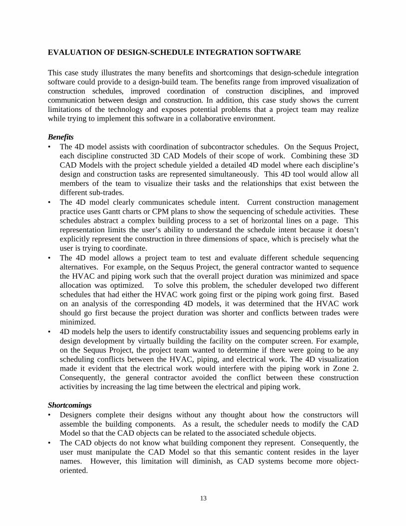
This case study illustrates the many benefits and shortcomings that design-schedule integrationsoftware could provide to a design-build team. The benefits range from improved visualization ofconstruction schedules, improved coordination of construction disciplines, and improvedcommunication between design and construction. In addition, this case study shows the currentlimitations of the technology and exposes potential problems that a project team may realizewhile trying to implement this software in a collaborative environment.
Benefits• The 4D model assists with coordination of subcontractor schedules. On the Sequus Project,
each discipline constructed 3D CAD Models of their scope of work. Combining these 3DCAD Models with the project schedule yielded a detailed 4D model where each discipline’sdesign and construction tasks are represented simultaneously. This 4D tool would allow allmembers of the team to visualize their tasks and the relationships that exist between thedifferent sub-trades.
• The 4D model clearly communicates schedule intent. Current construction managementpractice uses Gantt charts or CPM plans to show the sequencing of schedule activities. Theseschedules abstract a complex building process to a set of horizontal lines on a page. Thisrepresentation limits the user’s ability to understand the schedule intent because it doesn’texplicitly represent the construction in three dimensions of space, which is precisely what theuser is trying to coordinate.
• The 4D model allows a project team to test and evaluate different schedule sequencingalternatives. For example, on the Sequus Project, the general contractor wanted to sequencethe HVAC and piping work such that the overall project duration was minimized and spaceallocation was optimized. To solve this problem, the scheduler developed two differentschedules that had either the HVAC work going first or the piping work going first. Basedon an analysis of the corresponding 4D models, it was determined that the HVAC workshould go first because the project duration was shorter and conflicts between trades wereminimized.
• 4D models help the users to identify constructability issues and sequencing problems early indesign development by virtually building the facility on the computer screen. For example,on the Sequus Project, the project team wanted to determine if there were going to be anyscheduling conflicts between the HVAC, piping, and electrical work. The 4D visualizationmade it evident that the electrical work would interfere with the piping work in Zone 2.Consequently, the general contractor avoided the conflict between these constructionactivities by increasing the lag time between the electrical and piping work.
Shortcomings• Designers complete their designs without any thought about how the constructors will
assemble the building components. As a result, the scheduler needs to modify the CADModel so that the CAD objects can be related to the associated schedule objects.
• The CAD objects do not know what building component they represent. Consequently, theuser must manipulate the CAD Model so that this semantic content resides in the layernames. However, this limitation will diminish, as CAD systems become more object-oriented.

14
• A schedule needs to exist before a 4D model can be built. Many team members would havelike to create the schedule right in the 4D system.
• To link the CAD Model and Schedule Model requires significant understanding of howJacobus creates objects and classes from the CAD and Schedule Models.
Avoiding spatial conflicts during construction is a key concern for all disciplines of a projectteam. Significant efforts are pursued to make sure conflicts are avoided and crews are able towork productively. These efforts include the creation of detailed construction schedules, weeklycoordination meetings, and the use of overlays of subcontractor design drawings. Although thesemethods can be helpful, they fail to explicitly show the physical relationships betweensubcontractor work and the spatial requirements of each trade as construction progresses. Theuse of 4D CAD on the Sequus project has demonstrated that this tool effectively represents thespatial needs of each discipline simultaneously, allows a project team to evaluate differentsequencing alternatives, exposes potential constructability issues, and improves thecommunication and coordination between sub-trades.
ORGANIZATIONAL IMPACTS
The implementation of design, cost and schedule integration technologies are likely to changethe roles of each discipline in the design and construction process. This study suggests thatowners, designers and builders of facilities will need to develop new skills and implementorganizational changes to take advantage of the benefits offered by this technology and to staycompetitive in this changing market.
OwnersOwners could benefit from the use of design, cost and schedule integration software for thedesign and construction of new facilities and for retrofit work. Potential benefits includeimproved visualization of construction schedules and the ability to quickly assess the cost impactof different design and specification changes. These benefits will be realized if owners are ableto bring a project team together early in the design process. In our experience, it is critical forthe successful integration of design, cost and schedule information to have a project teamassembled from the very start of the project so that team members can share design informationthroughout the design process. The project team needs to develop detailed 3D CAD modelscollaboratively. As for the actual construction, there is no single entity that has all the expertiseto build a complete and accurate 3D model. This collaborative process will require extensivecommunication and assurances that each member is on the same page. At the end of the project,the detailed 3D CAD model can be transferred to the owner to assist in facility maintenance andoperations.
The representative for Sequus Pharmaceuticals selected this project team partly because of thebenefits offered by this technology. The main selling points from his perspective were the rapidresponse to what-if scenarios and the improved cost and time control. In addition, he felt that thedetailed 3D CAD models developed would help to avoid conflicts during construction resultingin lower construction costs. Finally, he thinks the detailed 3D CAD models could be used after
15
construction for validation, maintenance and operation, and budgeting for future remodels orexpansion.
Architects and EngineersDesigners working in a project team performing design, cost and schedule integration will spendmore time orchestrating the collaborative design process and less time performing detaileddesign. They will establish the overall design process, develop the design specifications, andwork collaboratively with all members of the project team. They will work closely with thegeneral contractor in design development because the general contractor will provide input onhow to build the CAD model so that the appropriate CAD dimensions can be extracted fordesign-cost integration and so that a 4D model can be built quickly. Designers also need to workclosely with subcontractors who perform detailed design for their disciplines.
The project architect for Flad worked closely with Hathaway in the development of thearchitectural design. This collaboration allowed Hathaway to utilize the design information toperform design-cost integration. Hathaway provided input that included suggestions on how tomodel certain CAD objects and what objects to include in the CAD model. For example,Hathaway advised Flad to draw polylines for the ceiling and flooring so that the area could beextracted for estimating purposes. Flad would need to include this information when designingin the traditional process, but through collaboration was able to create design information thatallowed the constructors to better utilize the design.
Flad also benefited from Ketiv's modeling capabilities. They were able to include specificationsin the CAD objects themselves. In the traditional process, there is no link between the designedobject and its specification. This linking allows the designer to better control the design processand manage design changes. In addition, Flad utilized Ketiv's 3D modeling capabilities.Traditionally, Flad would have created 2D plans and 2D elevations separately. There would beno link between the plans and elevations. Designing in 3D allowed Flad to create plans andelevations in one step. This link was particularly useful when the design changed, as Flad couldmake all modifications in one model.
General ContractorsGeneral contractors will need to change certain business practices and develop new skills to takeadvantage of the benefits that design, cost and schedule integration software provides. Generalcontractors will need training in CAD software so that they are able to manipulate CAD modelsand interpret how the CAD objects have been drawn. In addition, to perform design-costintegration, general contractors will provide input to designers so that the CAD objects are drawna certain way and the appropriate CAD dimension is extracted for each estimating item. Finally,general contractors are likely to become the keeper of the models, as illustrated by Figure 3.Design information will be transferred by the designer to the general contractor and then fromthe general contractor to all the subcontractors. This flow of information will continuethroughout the project as design changes are incorporated and propagated.
The project manager for Hathaway believes that the total estimating time could be reduced by25% by using design-cost integration and the time to determine the cost impact of some what-ifscenarios could be reduced by 50%. Hathaway compared estimating methods for the Sequus
16
Project by creating an estimate using traditional methods and creating an estimate using theCAD-estimate link. The two estimates were within 5% in terms of total cost. In addition, acomparison of the two estimates showed that there was a quantity takeoff error in the estimatecreated using traditional methods. Furthermore, estimates created using the CAD-estimate linkprovide a record as to how the quantities were derived. The project manager that created theestimate using traditional methods had left the company and there were no records that showedwhat was included in some of the estimating items or how the quantities were derived.Therefore, Hathaway believes the benefits offered by this technology justify further commitmentand plans on using this technology on future projects.
The 3D models also helped the project manager of Hathaway to better understand the designintent. In current practice, builders of facilities use 2D plans and sections to deduce the 3Ddesign. This process often leads to misinterpretation and differing perspectives within a projectteam. By having all members of a project team design in 3D from the very start of the project,there is more assurance that all disciplines have a common perspective of the final product. Inaddition, the 3D models can be utilized to create a 4D model of the facility design. The projectmanager for the Sequus Project feels that 4D models will be particularly useful in coordinatingconstruction tasks and communicating the intent of the construction schedule.
SubcontractorsSubcontractors will work collaboratively with architects and engineers in the development ofdetailed designs for their disciplines. They will become more active in the early phases of designdevelopment as the architect and engineer develop the specifications and schematics that formthe basis for the subcontractor's design. They are interested in being in control of the detaileddesign information so they can use it to automate the fabrication of components. However, weforesee that the subcontractors’ detailed design will still require the approval of the architect andengineer through the shop drawing process. As a result, subcontractors will need to developCAD modeling capabilities and would benefit from CAD software that is specifically designedfor their discipline. Some subcontractors are already benefiting from 3D CAD modelingsoftware for fabrication as well. In addition, since subcontractors will become more active in thedesign process, they will also be able to assist the general contractor in the coordination of all thesubcontractor trades throughout the project delivery process.
Rountree Plumbing understands the benefits of linking design and cost information but believesthat this process should be accomplished in-house. On the Sequus Project, we created a centralestimating database that included all the disciplines' estimating items, and the General Contractorperformed the integration. Ideally, Rountree would perform this integration in-house by linkingtheir estimating software (QuickPen) with their CAD software (Multi-Pipe). Unfortunately,there currently is no link electronic between QuickPen and Multi-Pipe.
Rountree Plumbing has much experience in 3D modeling and believes it offers substantialbenefits. They have used 3D models on past projects to assist in coordination with other trades,to plan daily work activities, and for fabrication. Rountree Plumbing also believes that 4Dmodeling will further assist in coordination with other subcontractors and will allow them toassist general contractors in the coordination process.
17
Rountree Plumbing has already witnessed some changes in their roles in the project team and inthe way they manage their construction tasks. They are performing more detailed design asevidenced by their experience in 3D modeling on past projects. On these projects, they receivedschematic designs from the Engineer and created detailed 3D CAD models independently. Theyhave also trained some managers in CAD modeling so the field crews can use the models to plandaily work tasks and to perform fabrication.
CONCLUSIONS
Integrating design, cost, and schedule information can help a project team to improve theefficiency of the planning and estimating processes. Design-cost integration supports theautomatic calculation of material quantities, thus shortening estimating time and eliminating theduplication of effort that exists in current estimating practices. In addition, it allows a projectteam to quickly evaluate the cost impact of different design and specification alternatives, andprovides electronic validation that all the items in the CAD model have been included in theestimate. Integrating design and schedule information allows construction professionals tovisualize the construction process and evaluate the constructability of a proposed constructionsequence. The Sequus Project team has successfully performed design, cost and scheduleintegration and demonstrated the status of this software and the resource requirements necessaryto accomplish these tasks on an actual project. This study shows that owners, designers andbuilders of facilities will need to develop new skills and implement organizational changes totake advantage of the benefits offered by this technology. Whenever possible, electronicinformation should be created by the party that derives the most benefits from a complete andaccurate 3D model. Therefore, owners will need to bring a project team together early in theproject to capitalize on the benefits of this technology. Designers will need to focus more on theoverall design and coordination of design tasks and less on detailed design. General contractorswill need to learn to manipulate 3D CAD models, work more closely with the designers indesign development, and provide input on design representation so that the designs are moreusable for the constructor. Subcontractors will also need to learn design software, as they will beperforming more detailed design, working more closely with the architects and engineersthroughout the design process, and addressing coordination issues early in design development.In summary, this study has demonstrated that electronic design, cost, and schedule integration ispossible with today’s off-the-shelf software products. The resulting benefits include fasterestimating time, fewer takeoff errors, better documentation and reproducibility of the estimatingprocess, and the ability to release a construction schedule electronically with the whole projectteam prior to construction.

18
ACKNOWLEDGEMENTS
In addition to the companies mentioned in this report, we would like to thank Mazzetti &Associates for their financial support of this study.
We would also like to thank the following software vendors for their software donations andtechnical support:• Autodesk – AutoCAD R14: http://www.autodesk.com• Jacobus Technology – Schedule Simulator: http://www.jacobus.com• Ketiv Technologies - Archt: http://www.ketiv.com• Microsoft – Project: http://www.microsoft.com• Timberline – Precision Estimating: http://www.timberline.com
REFERENCES
Cleveland, A.B. Jr. (1989). Real-Time Animation of Construction Activities, Proc. of ConstructionCongress I - Excellence in the Constructed Project. San Francisco, CA: ASCE, 238-243.
Collier, E. and Fischer, M.(1996). Visual-Based Scheduling: 4D Modeling on the San Mateo CountyHealth Center, Proceedings of the Third Congress on Computing in Civil Engineering, JorgeVanegas and Paul Chinowsky (Eds.), ASCE, Anaheim, CA, June 17-19, 1996, 800-805.
Nevins, D.P., et al. (1991). Graphical Database for Construction Planning and Cost Control,Construction Congress '91, Cambridge, MA, USA. Preparing for Construction in the 21stCentury Construction Congress '91. ASCE, 266-271.
Teicholz, P., and Fischer, M. (1994). Strategy for Computer Integrated Construction Technology,Journal of Construction Engineering and Management, 1994. ASCE, 120(1), 117-131.
Wickard, D.A., et al. (1989). Construction CAE: Integration of CAD, Simulation, Planning andCost Control, Proceedings of the 51st American Power Conference 1989, Chicago, IL, USA.Proceedings of the American Power Conference v 51, Chicago, IL, USA, 983-987.
Williams, M. (1996). Graphical Simulation for Project Planning: 4D-Planner, Computing inCivil Engineering: Proceedings of the Third Congress held in conjunction with A/E/CSystems '96, Anaheim, California, ASCE.