Embed Size (px)
Citation preview

Industrial and Off-HighwayAmericardan Universal Driveshafts
A L T R A I N D U S T R I A L M O T I O N

1 www.ameridrives.com P-7420-AC 3/18
Ameridrives designs, sources, manufactures and tests
a complete driveshaft product offering with industry
leading performance that includes genuine Spicer
Universal Joints, patented INTER-SEALED slip sections,
wing style (including the former Twin Disc line), and DIN
style designs. If you have a driveshaft need, we will
meet that need by providing a product of the highest
quality, and highest value in its class.
We Offer • Authorized Spicer Components upon Request
• DIN or SAE Designs
• Wing Style Designs
• Closed Eye Designs
• Custom or Standard Solutions
• Complete Assemblies or Individual Components
• Custom Design and Manufacturing
• Complete Rebuild Services of any Shaft
Configuration
Call Today With Your Application Requirements And We Will • Select the appropriate joint, slip, and shaft
length based on your application
• Design a solution and quote
• Upon receipt of your order source or
manufacture the components
• Assemble, weld, test and ship to you
Visit us on the web at:
WWW.AMERIDRIVES.COM
Altra Industrial Motion
Altra is a leading global designer and manufacturer of quality power transmission and motion control products utilized on a wide variety of industrial drivetrain applications. Altra clutches and brakes, couplings, gearing and PT component product lines are marketed under the industries most well known manufacturing brands. Each brand is committed to the guiding principles of operational excellence, continuous improvement and customer satisfaction. Highly-engineered Altra solutions are sold in over 70 countries and utilized in a variety of major industrial markets, including food processing, material handling, packaging machinery, mining, energy, automotive, primary metals, turf and garden and many others.
Altra’s leading brands include Ameridrives, Bauer Gear Motor, Bibby Turboflex, Boston Gear, Delroyd Worm Gear, Formsprag Clutch, Guardian Couplings, Huco, Industrial Clutch, Inertia Dynamics, Kilian, Lamiflex Couplings, Marland Clutch, Matrix, Nuttall Gear, Stieber, Stromag, Svendborg Brakes, TB Wood’s, Twiflex, Warner Electric, Warner Linear and Wichita Clutch.
VISIT US ON THE WEB AT ALTRAMOTION.COM

P-7420-AC 3/18 www.ameridrives.com 30
Data Form
General Machinery Application Data for Selection and Design
Customer: ______________________________________________
Contact Name: __________________________________________
Applications: ___________________________________________
Inquiry No.: _________________________________________________
No. of Units: ________________________________________________
Phone: _____________________________________________________
Fax: ________________________________________________________
Complete the following information for your application:1. Motor Horsepower______________________________________2. Motor RPM (Min. and Max.)______________________________3. Required Service Factor_________________________________4. Operating RPM__________________________________________5. Reducer Ratio__________________________________________6. Normal Operating Torque ________________________________7. Shaft Separation (Min. and Max.)__________________________8. Required Shaft Axial Slide _________________________________9. Operating Angle________________________________________9a. Operating Offset_______________________________________
10. No Load Angle________________________________________10a. No Load Offset_________________________________________11. Horizontal Application___________________________________11a. Vertical Application_____________________________________12. Drive End Bore & Keyway________________________________ 13. Driven End Bore & Keyway_______________________________ 14. Diameter Limitations______________________________________ 15. Desired B-10 Life Hours___________________________________
Comments or special conditions such as: Ambient temperature, atmospheric, etc.: _________________________________________ ________________________________________________________________________________________________________________________________________________________________________________________________________________________________________
Note: If bolting to existing drive and driven flanges, please specify flange diameter, pilot diameter, bolt circle, number of bolts and
bolt size: ________________________________________________________________________________________________________________________________________________________________________________________________________________________________
Space provided below for sketch.
CAUTION:This product will be selected based on the information supplied to Ameridrives by the Purchaser. Complete and accurate information will help to minimize errors and misapplications. Further, it is the responsibility of the Purchaser to assure the interface connection between couplings and connected equipment (flanges, bolting, keys, hydraulic fits, etc.), are capable of handling anticipated loads. Ameridrives will not be responsible for errors due to inaccurate or incomplete information supplied to Ameridrives.
1802 Pittsburgh AvenueErie, PA. 16502-1943 Phone: 814-480-5000Fax: 814-453-5891www.ameridrives.com

P-7420-AC 3/18 www.ameridrives.com 2
Table of Contents Introduction .......................................................................................1, 2
Advantages & Applications ................................................................3, 4
Design Features & Selection ..............................................................5-10
2000 Series .......................................................................................11-13
3000 & 5000 Series ..........................................................................14-21
Wing Bearing Series ..........................................................................22-25
Custom Slip Lengths .........................................................................26
Kinematics & Reference Data ............................................................27-29
Application Data Sheet ......................................................................30
Ameridrives1802 Pittsburgh Avenue • Erie, PA. 16502814-480-5000 • Fax: 814-453-5891www.ameridrives.com
3 www.ameridrives.com P-7420-AC 3/18
Advantages and Design Typical Applications
Advantages and Features• High torque capacity
• Long bearing life
• High operating angle capability
• One piece yoke and bearing housing construction
• Eliminates unnecessary bolted connections and serrations in yokes
• Heat treated alloy steel components
• Ideal loading across entire bearing length due to balanced deflection between yokes and cross
• Replaceable inner bearing race on size U3440 and larger significantly reducing cross-maintenance expenses
• Available in four basic types
• Technical support and engineering services available
• Extensive repair facility
• Special sizes and designs available upon request
• Large sizes available
Typical ApplicationsFollowing is a partial list of applications for the Ameridrives Universal Joint:
Metals Industry(Steel, Aluminum, Copper and Brass)
Agitators
Balancing Machines
Blowers and Fans
Compressors
Conveyors
Cooling Tower Fans
Cranes and Hoists
Crushers
Farming Equipment
Generators
Glass Manufacturing
Lumber Mills
Marine Propulsion
Mining Equipment
Oil and Gas – Drilling – Pumps
Packaging
Paper Mills – Calender Drives – Sizing and Press Rolls – Couch Rolls – Process Pumps
Plastic Manufacturing – Melt Pumps
Printing Presses
Pumps – Irrigation – Lift – Sewage
Railway Drives
Rubber Processing – Mixers – Calenders
Shredders
Textile Equipment
Bar and Rod Mills
Cold Reduction
Continuous Casters
Hot Strip Mills
Levelers
Payoff Reels – Pinch Rolls – Coilers – Brush Rolls – Bridles – Flatteners – Slitters
Pipe Mills
Runout Tables – Piercers – Transfer Cars – Structural Mills
Scale Breakers
Shears
Side Trimmers
Straighteners
Temper Mills
Tension Reels
Tube Mills
Vertical Edgers
Wire Mills

P-7420-AC 3/18 www.ameridrives.com 4
Design Variations Custom Applications
CAT24
B A
Short Travel Capability
Long Travel Capability With Expansion and CV Joint
Torsionally Dampened Driveshafts
5 www.ameridrives.com P-7420-AC 3/18
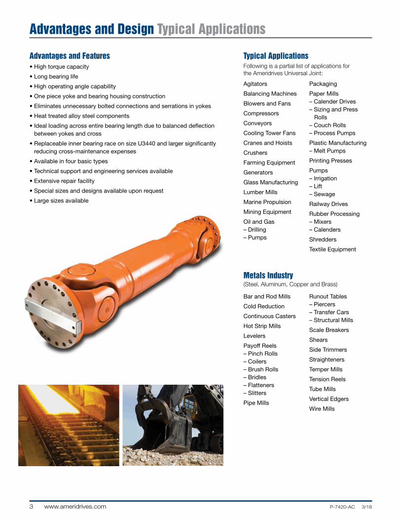
Design Features Round Bearing
2000 Series
Sizes U2131-U2155: Needle bearing design. Bearing caps are retained by snap rings.
Sizes U2160-U2188: Needle bearing design. Bearing caps are retained by bolts.
Sizes U2192: Uses two rows of roller bearings. Bearing caps are retained by snap rings. Lube fitting in center of cross.
Authorized Spicer Components upon Request

P-7420-AC 3/18 www.ameridrives.com 6
Design Features Round Bearing
Inner Bearing Race for U3440-U3800 – Replaceable inner bearing race manufactured from bearing steel fits over forged alloy cross in select sizes. This design provides long bearing life and permits for economical replacement of bearing assemblies.
Radius Shoulder Trunnions – Shoulder has generous radius at base of cross trunnion to reduce stress concentrations.
Double-Lip Seal – Abrasion resistant multi-lip extruder type seals to insure integrity of the bearing lube reservoir. 4 Point lubrication with lube fittings on each bearing housing.
Thrust Bearings – Each cap has a filled nylon compound thrust washer to prevent steel on steel contact of the trunnion to minimize friction and prevent galling under heavy loads. Filled nylon thrust bearings automatically adjust themselves to compensate for minor deflections.
Crowned Rollers – Eliminates stress concentrations at the ends of the rollers. The reduction in stress contributes significantly to increased bearing (B10) life. Three rows of rollers are used to distribute load over length of trunnion.
Zero Clearance Assembly – Cross and bearing assembled for zero radial clearance for optimum thrust and radial bearing performance and elimination of radial whirl associated with vibrations.
Contoured Bearing Caps – Allows for longer cross journals for increased torque and bearing capacity.
Flanges – Commonly supplied with face pad or hirth flanges to provide a backlash free connection capable of transmitting high torques.
Straight Roller Crowned Roller
Stress
Stress
Straight Roller Crowned Roller
Stress
Stress
Cross
Lube Fitting
RetainingRing
SpringWasher
Crowned Rollers
Retainer Ring
Lip Seal
Plug
Bearing Housing
ThrustWasher
AlloyCross
InnerRace
Lip Seal
RetainingRing
Crowned Rollers
Retainer Ring
ReducerLubeFitting
Bearing Housing
ThrustWasher
SpringWasher
Higher TorqueU3055 - U3390 / U5225 - U5800
AmericardanU3440 - U3800
Straight Roller Crowned Roller
Stress
Stress
Straight Roller Crowned Roller
Stress
Stress
Sizes U3055-U3100: Needle bearing design. Lube fitting in center of cross.
Sizes U3115-U3200: Uses two rows of roller bearings. Bearing caps are retained by snap rings. Lube fitting in center of cross.
Sizes U3225-U3390, U5225 - U5390: Uses two rows of roller bearings. Bearing caps are retained by snap rings. Lube fittings in center bearing cap is optional.
Sizes U3440-U3920, U5440 - U6200: Uses three or more rows of roller bearings. Includes replaceable inner races in the bearing assemblies. Bearing caps are retained by large snap rings. Lube fittings are in each bearing cap.

7 www.ameridrives.com P-7420-AC 3/18
Design Features Wing Bearing
RelievedEnd Roller
Straight Roller
Stre
ss
Stre
ss
Tapered-Shoulder Trunnions – Shoulder is tapered at base of the cross trunnions to reduce bending stresses. This construction also protects the seal from accidental damage during assembly.
Double-Lip Seal – Provides positive protection against grease leakage.
Thrust Bearings – Each cap has a 30% glass filled nylon compound thrust bearing to prevent steel-on-steel contact of trunnions to minimize friction and prevent galling under heavy loads. Glass-filled nylon bearings automatically adjust themselves to compensate for minor deflections.
Accurately-Guided Roller Bearings – A standard and exclusive feature. Cage prevents skewing by holding each roller parallel to the axis of the trunnion. Each roller thus carries its full share of the bearing load.
Also, this type bearing retains more grease.
Permanent Grease Feature – Proven successful over years of service in crawler tractor, off-highway trucks and front-end loader applications, Ameridrives now offers this feature to all users. Cross and bearing assemblies are sealed for the normal life of the U-joint driveshaft. This prevents dirt and contamination from entering cross and bearing assemblies through the grease gun from poorly maintained servicing equipment and there is no longer a need to grease an inaccessible U-joint buried beneath shrouds and guards.
“Relieved End” Rollers – Rollers are slightly tapered to eliminate stress concentration normally encountered at the ends (see sketch). The more uniform stress pattern thereby gained adds appreciably to bearing life.
• Accurately guided roller bearings have hardened steel phosphate coated cages.• .0001" roller manufacturing tolerance for improved bearing life.• 8620 Vacuum De-Gassed Steel Bearing Caps
and Crosses. Clean steel improves fatigue properties.
• Improved thrust bearing-glass filled nylon compound material.
2C - 15C J170 - J1200

P-7420-AC 3/18 www.ameridrives.com 8
Custom Slip Design
Ameridrives offers a wide array of custom slip designs to fit your unique needs and long travel applications. Long travel slip assemblies are made possible by the inverted spline allowing extended slip lengths far beyond the limits of other designs. Our patented Inter-Sealed® design is the most versatile with options of having a self-lubricating coating on the splines to reduce axial loads and prevent premature wear. A positive full contact seal ensures that the grease remains inside and the contaminants remain out. For more information regarding custom slip lengths please contact an Ameridrives application engineer.
9 www.ameridrives.com P-7420-AC 3/18
Selection Information Speed Limits
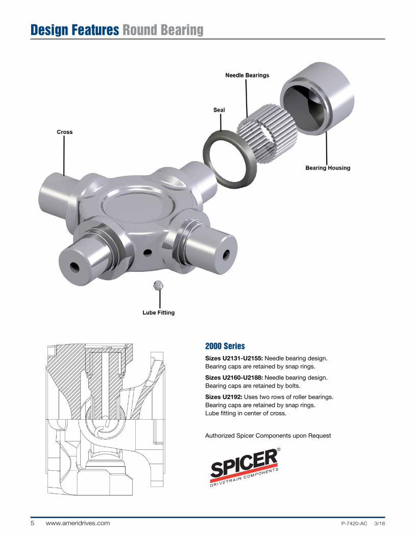
I. Speed Limit Based on Limits of Mass Acceleration When universal joints are operated at any angle greater than zero, the center section of the universal joint always runs irregularly, being accelerated and decelerated twice in every revolution. The maximum values of mass acceleration torque arising here are dependent on the operating speed and angle of deviation ß and upon the moment of inertia of the center shaft section [ RPM x A ].
To ensure smooth running of the universal joint, the mass acceleration torque must not be allowed to exceed the limits shown in Table 1.
II. Speed Limit Based on Lateral Critical Speed In applications where long lengths of shafts are required, the speed is restricted by the lateral critical speed of the center section. This speed is a function of the center tube diameter wall thickness, and the effective length. The maximum operating speed must be less than the lateral critical speed Nc shown in Table 2.
NOTE: Allowable Operating Speed = Nc x .75.
In many applications, operation at 1/2 critical speed will also create unacceptable vibration. For these applications the operating speed should be 8% above or below 50% of the maximum indicated.
For flange-to-flange lengths greater than shown, or if allowable speed is exceeded, contact Ameridrives.
III. Balancing All standard universal joints under 300 RPM are supplied unbalanced. Between 300-850 RPM they are balanced if required. Consult factory for further information. Over 850 RPM all universal joints are normally supplied balanced. Please consult the factory for special balancing requirements.
Table 1
Table 2
The speed limits on this page are only a guide. The actual limits are determined by the characteristics of the system in which the universal joint is installed.
2188-3175
2131-3200
32003225
3225
2188-3175
2131-3200
32003225
3225

P-7420-AC 3/18 www.ameridrives.com 10
Selection ProcedureSee page 30 for Application Data sheets for easy selection.
Types of torque ratings are given for each joint size.
Endurance torque (Tdw) is the normal rating for fully reversing torque based on material strength.
Bearing Life torque (BL) is the bearing life rating of the universal joint. This torque is based on the B-10 life of the universal joint bearings. The life torque values listed are based on 5000 hours B-10 bearing life at 3° misalignment and 100 RPM. B-10 life is defined as the minimum life expectancy for a 90% probability of survival. Typically the average actual operating life of the bearings is 5X the calculated B-10 life.
Peak torque (TK) is the maximum allowable torque based on the yield strength capacity of the joint.
The torque ratings are based on material strength. When approaching these limits the capacity of the desired flange connection should be verified. When the selection torque (Ts) approaches the endurance torque (Tdw) or when the maximum torque approaches the peak torque capacity (TK) of the universal joint, integral face pads are recommended. The number of pads and bolts are customized on a per application basis. Hirth radial teeth are also available on a per application basis.
Universal Joint Selection I. Calculate application torque (Ta) and
selection torque (Ts).
Ta = HP x 63025
N
Ta = KW x 9550
N
N = Speed (RPM)
Ts = Selection Torque = Ta x Service Factor
Ts must be less than Tdw for reversing torque applications or Tow for one way pulsating torque applications.
II. Check to see if life is sufficient.
Lh = 1.5 x 10⁶
[ Bl]
A x N
T
Where: Lh = B-10 Life in Hours A = Operating Angle in Degrees N = Speed (RPM) BL = Life Torque Ta = Application Torque
III. Duty Cycle: In applications where the torque, speed and operating angle vary predictably during a typical load cycle or operational sequence, a duty cycle can be determined. First the load cycle must be analyzed and divided into groups of fixed combinations of torque, speed and operating angle. These groups represent percentages of the total operating time of the load cycle. Life expectancy can then be calculated using Miner’s Theory, which takes into account the cumulative effect resulting from operating at varying conditions.
The total life expectancy can be calculated using the following equation:
Total Life 1Expectancy
= N1 + N2 + N3 + . . . +
Nm
— — — —
L1 L2 L3 Lm
Where:
N1 = fraction of total, time at operating condition 1
L1 = life expectancy at operating condition 1 (hours)
m = total number of operating conditions
IV. Determine Peak Torque conditions. Tk must exceed the maximum operating torque.
V.I Other considerations: There are many other items that can determine the size of a universal joint. These include:
1. Diameter and length limitations.
2. Bore size.
3. Equipment restrictions on forces and moments.
4. Speed limits (see Tables 1 and 2) a. due to mass acceleration as a
function of misalignment
4. b. critical speed of center shaft
Telescopic splines are available on ST and FT designs. The splined axial travel sections are required to accomodate movement of the driven end such as a roll position change or axle jounce. SF and FF shaft are properly selected for applications where the roll end has relatively small movements of the driven side along with a clearance or slip fit roll end connection. The amount of required axial movement can be calculated by multiplying the centerline to centerline of the universal joint yokes by 1 minus the cosine of the operating angle for each position.
Nitrided or coated splines are available on request.
Longer or shorter travel is available. Consult Ameridrives.
310
( lb. x in. )
( Nm )
( )
11 www.ameridrives.com P-7420-AC 3/18
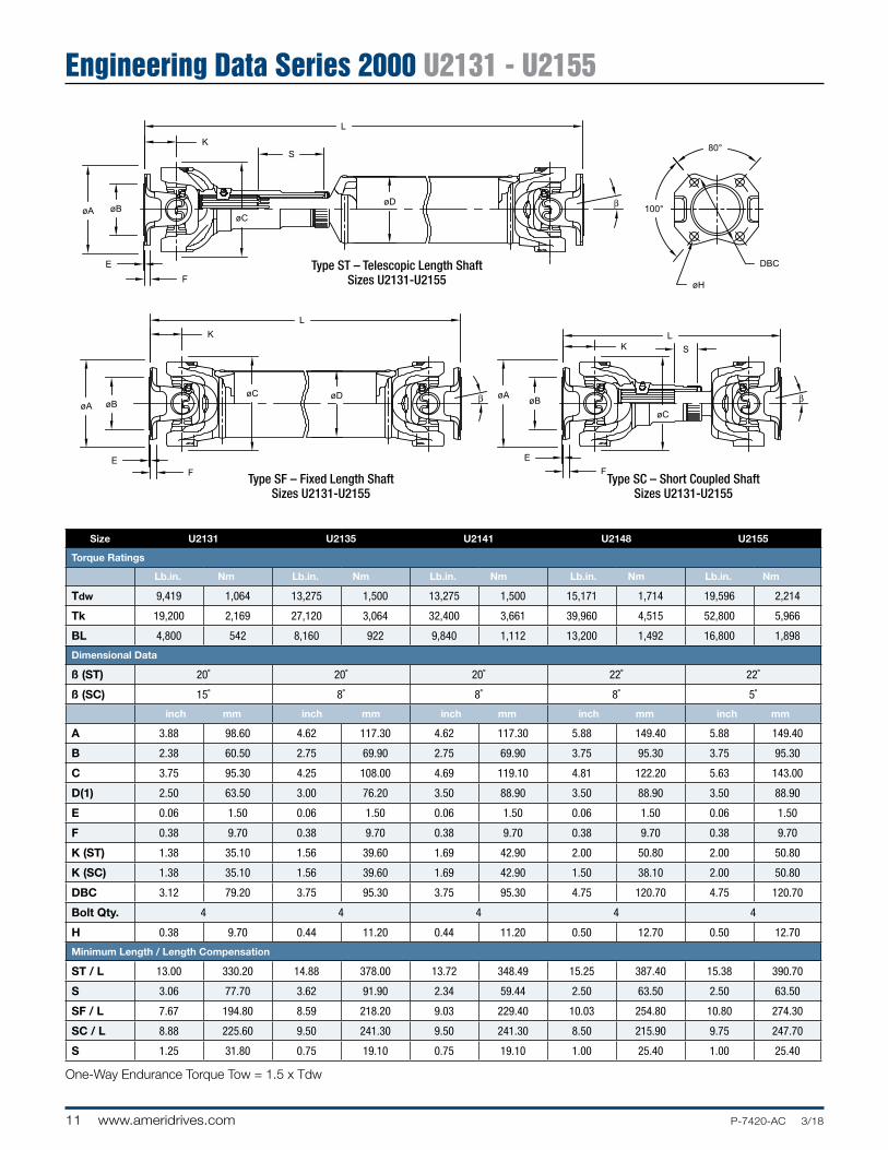
Engineering Data Series 2000 U2131 - U2155
L
KS
øBøC
øA
E
F
øD100°
80°
DBC
øH
L
øA øB
EF
øC
K
øAøB
E
F
øC
LK
øD
β
β β
S
Type SF – Fixed Length ShaftSizes U2131-U2155
Type SC – Short Coupled ShaftSizes U2131-U2155
Type ST – Telescopic Length ShaftSizes U2131-U2155
Size U2131 U2135 U2141 U2148 U2155
Torque Ratings
Lb.in. Nm Lb.in. Nm Lb.in. Nm Lb.in. Nm Lb.in. Nm
Tdw 9,419 1,064 13,275 1,500 13,275 1,500 15,171 1,714 19,596 2,214
Tk 19,200 2,169 27,120 3,064 32,400 3,661 39,960 4,515 52,800 5,966
BL 4,800 542 8,160 922 9,840 1,112 13,200 1,492 16,800 1,898
Dimensional Data
ß (ST) 20˚ 20˚ 20˚ 22˚ 22˚
ß (SC) 15˚ 8˚ 8˚ 8˚ 5˚
inch mm inch mm inch mm inch mm inch mm
A 3.88 98.60 4.62 117.30 4.62 117.30 5.88 149.40 5.88 149.40
B 2.38 60.50 2.75 69.90 2.75 69.90 3.75 95.30 3.75 95.30
C 3.75 95.30 4.25 108.00 4.69 119.10 4.81 122.20 5.63 143.00
D(1) 2.50 63.50 3.00 76.20 3.50 88.90 3.50 88.90 3.50 88.90
E 0.06 1.50 0.06 1.50 0.06 1.50 0.06 1.50 0.06 1.50
F 0.38 9.70 0.38 9.70 0.38 9.70 0.38 9.70 0.38 9.70
K (ST) 1.38 35.10 1.56 39.60 1.69 42.90 2.00 50.80 2.00 50.80
K (SC) 1.38 35.10 1.56 39.60 1.69 42.90 1.50 38.10 2.00 50.80
DBC 3.12 79.20 3.75 95.30 3.75 95.30 4.75 120.70 4.75 120.70
Bolt Qty. 4 4 4 4 4
H 0.38 9.70 0.44 11.20 0.44 11.20 0.50 12.70 0.50 12.70
Minimum Length / Length Compensation
ST / L 13.00 330.20 14.88 378.00 13.72 348.49 15.25 387.40 15.38 390.70
S 3.06 77.70 3.62 91.90 2.34 59.44 2.50 63.50 2.50 63.50
SF / L 7.67 194.80 8.59 218.20 9.03 229.40 10.03 254.80 10.80 274.30
SC / L 8.88 225.60 9.50 241.30 9.50 241.30 8.50 215.90 9.75 247.70
S 1.25 31.80 0.75 19.10 0.75 19.10 1.00 25.40 1.00 25.40
One-Way Endurance Torque Tow = 1.5 x Tdw
P-7420-AC 3/18 www.ameridrives.com 12
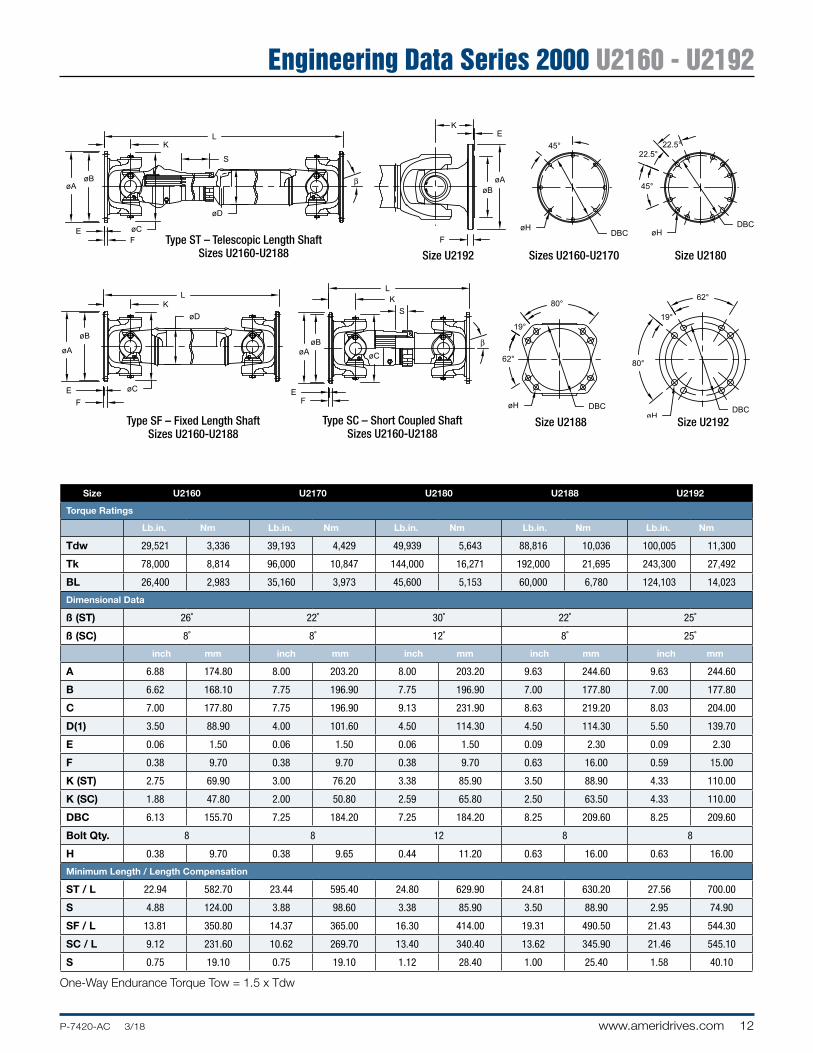
Engineering Data Series 2000 U2160 - U2192
øBøA
EF
LK
S
øA
øB
E
F
KL
øD
øC
øC
øAøB
K
øC
EF
øD
L
S
45°
DBCøH
45°
22.5°22.5°
DBCøH
DBCøH
62°
19°
80°
19°
80°
62°
DBCøH
K
øAøB
F
E
β
β
Type SC – Short Coupled ShaftSizes U2160-U2188
Type SF – Fixed Length ShaftSizes U2160-U2188
Type ST – Telescopic Length ShaftSizes U2160-U2188 Size U2192 Sizes U2160-U2170 Size U2180
Size U2188 Size U2192
Size U2160 U2170 U2180 U2188 U2192
Torque Ratings
Lb.in. Nm Lb.in. Nm Lb.in. Nm Lb.in. Nm Lb.in. Nm
Tdw 29,521 3,336 39,193 4,429 49,939 5,643 88,816 10,036 100,005 11,300
Tk 78,000 8,814 96,000 10,847 144,000 16,271 192,000 21,695 243,300 27,492
BL 26,400 2,983 35,160 3,973 45,600 5,153 60,000 6,780 124,103 14,023
Dimensional Data
ß (ST) 26˚ 22˚ 30˚ 22˚ 25˚
ß (SC) 8˚ 8˚ 12˚ 8˚ 25˚
inch mm inch mm inch mm inch mm inch mm
A 6.88 174.80 8.00 203.20 8.00 203.20 9.63 244.60 9.63 244.60
B 6.62 168.10 7.75 196.90 7.75 196.90 7.00 177.80 7.00 177.80
C 7.00 177.80 7.75 196.90 9.13 231.90 8.63 219.20 8.03 204.00
D(1) 3.50 88.90 4.00 101.60 4.50 114.30 4.50 114.30 5.50 139.70
E 0.06 1.50 0.06 1.50 0.06 1.50 0.09 2.30 0.09 2.30
F 0.38 9.70 0.38 9.70 0.38 9.70 0.63 16.00 0.59 15.00
K (ST) 2.75 69.90 3.00 76.20 3.38 85.90 3.50 88.90 4.33 110.00
K (SC) 1.88 47.80 2.00 50.80 2.59 65.80 2.50 63.50 4.33 110.00
DBC 6.13 155.70 7.25 184.20 7.25 184.20 8.25 209.60 8.25 209.60
Bolt Qty. 8 8 12 8 8
H 0.38 9.70 0.38 9.65 0.44 11.20 0.63 16.00 0.63 16.00
Minimum Length / Length Compensation
ST / L 22.94 582.70 23.44 595.40 24.80 629.90 24.81 630.20 27.56 700.00
S 4.88 124.00 3.88 98.60 3.38 85.90 3.50 88.90 2.95 74.90
SF / L 13.81 350.80 14.37 365.00 16.30 414.00 19.31 490.50 21.43 544.30
SC / L 9.12 231.60 10.62 269.70 13.40 340.40 13.62 345.90 21.46 545.10
S 0.75 19.10 0.75 19.10 1.12 28.40 1.00 25.40 1.58 40.10
One-Way Endurance Torque Tow = 1.5 x Tdw

13 www.ameridrives.com P-7420-AC 3/18
Companion Flange Dimensions U2131 - U2192
2000 SERIES
3000 SERIES
CLEARANCEBOLT REMOVAL
CLEARANCEBOLT REMOVAL
DESIGN 2
D2
d2 B
DESIGN 1
D1 d1
A
B
DESIGN 3DESIGN 2
D2
TO SUITd2
A
BB
DESIGN 1
D1 d1
A
B
CAT19
C
TE1
E1
E1
C
TE1
CE1
T
L1L2
Design 1 Design 2
Size U2131 U2135/U2141 U2148/U2155 U2160 U2170 U2180 U2188/U2192
Inch mm Inch mm Inch mm Inch mm Inch mm Inch mm Inch mm
A 3.88 98.60 4.63 117.60 5.88 149.40 6.88 174.80 8.00 203.20 8.00 203.20 9.63 244.60
B 2.38 60.50 2.75 69.90 3.75 95.30 6.62 168.10 7.75 196.90 7.75 196.90 7.00 177.80
E 0.08 2.00 0.08 2.00 0.08 2.00 0.04 1.00 0.04 1.00 0.04 1.00 0.11 2.80
F 0.38 9.70 0.50 12.70 0.38 9.70 0.38 9.70 0.38 9.70 0.50 12.70 0.38 9.70
L1 2.00 50.80 2.00 50.80 2.50 63.50 3.50 88.90 4.00 101.60 4.00 101.60 4.50 114.30
D1 2.44 62.00 2.88 73.20 3.75 95.30 5.25 133.40 6.38 162.10 6.38 162.10 6.88 174.80
d1 1.69 42.90 1.88 47.80 2.44 62.00 3.12 88.90 4.00 101.60 4.00 101.60 4.50 114.30
L2 2.50 63.50 3.00 76.20 3.50 88.90 5.00 127.00 6.00 152.40 6.00 152.40 6.00 152.40
d2 2.38 60.50 2.75 69.90 3.75 95.30 4.75 120.70 5.50 139.70 5.50 139.70 6.50 165.10
P-7420-AC 3/18 www.ameridrives.com 14
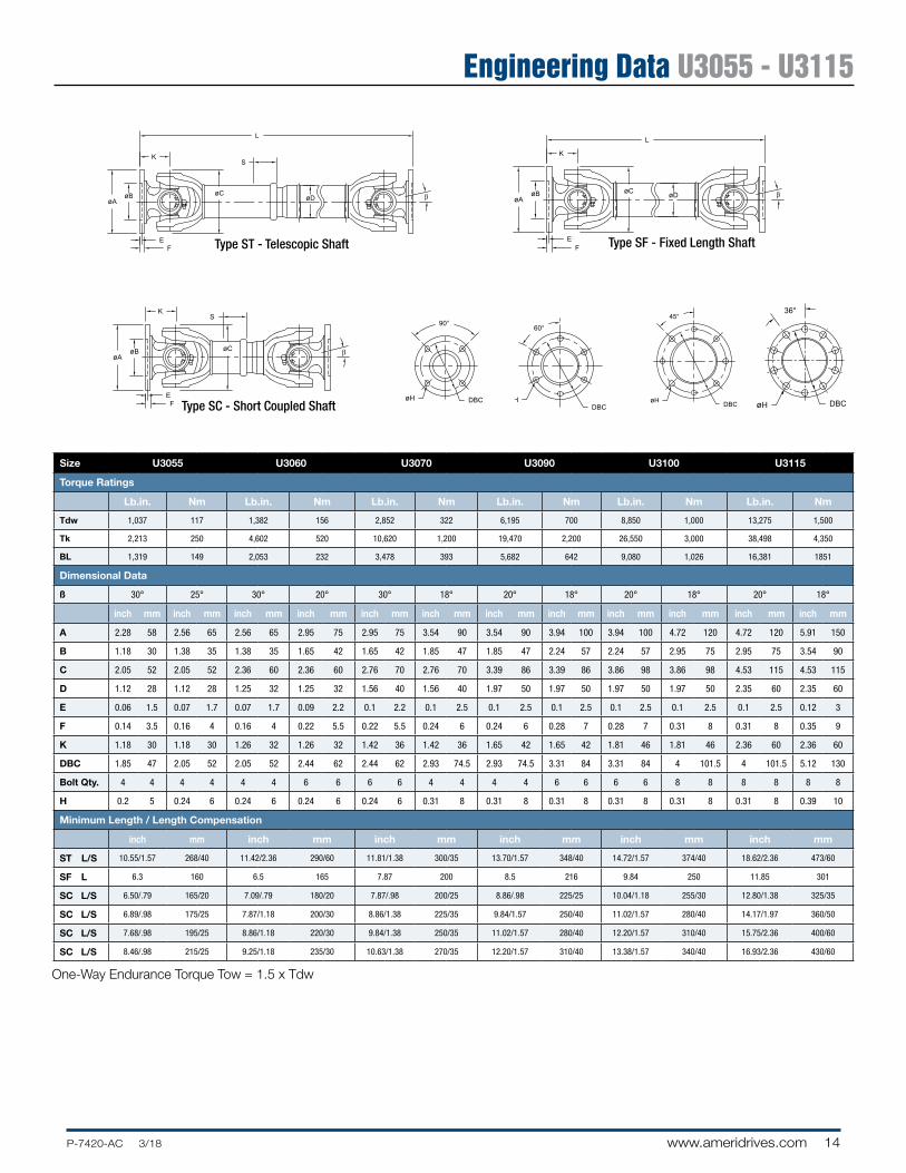
Engineering Data U3055 - U3115
øAøB
FE
K
L
S
øDøC
DBCøH
60°
øAøB
K
øC
EF
øD
L
øAøB
K
EF
øC
90°
DBCøH
45°
DBCøH
β
β
S
β
øAøB
FE
K
L
S
øDøC
DBCøH
60°
øAøB
K
øC
EF
øD
L
øAøB
K
EF
øC
90°
DBCøH
45°
DBCøH
β
β
S
β
øAøB
FE
K
L
S
øDøC
DBCøH
60°
øAøB
K
øC
EF
øD
L
øAøB
K
EF
øC
90°
DBCøH
45°
DBCøH
β
β
S
β
øAøB
FE
K
L
S
øDøC
DBCøH
60°
øAøB
K
øC
EF
øD
L
øAøB
K
EF
øC
90°
DBCøH
45°
DBCøH
β
β
S
β
øAøB
EF
K
øC
S
L
øD
FE
øAøB
K
øC
L
øD
øCøBøA
K
EF
L
S
øH DBC
36°45°
øH DBC
β
β
β
øAøB
FE
K
L
S
øDøC
DBCøH
60°
øAøB
K
øC
EF
øD
L
øAøB
K
EF
øC
90°
DBCøH
45°
DBCøH
β
β
S
β
øAøB
FE
K
L
S
øDøC
DBCøH
60°
øAøB
K
øC
EF
øD
L
øAøB
K
EF
øC
90°
DBCøH
45°
DBCøH
β
β
S
β
Type ST - Telescopic Shaft Type SF - Fixed Length Shaft
Type SC - Short Coupled Shaft
Size U3055 U3060 U3070 U3090 U3100 U3115
Torque Ratings
Lb.in. Nm Lb.in. Nm Lb.in. Nm Lb.in. Nm Lb.in. Nm Lb.in. Nm
Tdw 1,037 117 1,382 156 2,852 322 6,195 700 8,850 1,000 13,275 1,500
Tk 2,213 250 4,602 520 10,620 1,200 19,470 2,200 26,550 3,000 38,498 4,350
BL 1,319 149 2,053 232 3,478 393 5,682 642 9,080 1,026 16,381 1851
Dimensional Data
ß 30° 25° 30° 20° 30° 18° 20° 18° 20° 18° 20° 18°
inch mm inch mm inch mm inch mm inch mm inch mm inch mm inch mm inch mm inch mm inch mm inch mm
A 2.28 58 2.56 65 2.56 65 2.95 75 2.95 75 3.54 90 3.54 90 3.94 100 3.94 100 4.72 120 4.72 120 5.91 150
B 1.18 30 1.38 35 1.38 35 1.65 42 1.65 42 1.85 47 1.85 47 2.24 57 2.24 57 2.95 75 2.95 75 3.54 90
C 2.05 52 2.05 52 2.36 60 2.36 60 2.76 70 2.76 70 3.39 86 3.39 86 3.86 98 3.86 98 4.53 115 4.53 115
D 1.12 28 1.12 28 1.25 32 1.25 32 1.56 40 1.56 40 1.97 50 1.97 50 1.97 50 1.97 50 2.35 60 2.35 60
E 0.06 1.5 0.07 1.7 0.07 1.7 0.09 2.2 0.1 2.2 0.1 2.5 0.1 2.5 0.1 2.5 0.1 2.5 0.1 2.5 0.1 2.5 0.12 3
F 0.14 3.5 0.16 4 0.16 4 0.22 5.5 0.22 5.5 0.24 6 0.24 6 0.28 7 0.28 7 0.31 8 0.31 8 0.35 9
K 1.18 30 1.18 30 1.26 32 1.26 32 1.42 36 1.42 36 1.65 42 1.65 42 1.81 46 1.81 46 2.36 60 2.36 60
DBC 1.85 47 2.05 52 2.05 52 2.44 62 2.44 62 2.93 74.5 2.93 74.5 3.31 84 3.31 84 4 101.5 4 101.5 5.12 130
Bolt Qty. 4 4 4 4 4 4 6 6 6 6 4 4 4 4 6 6 6 6 8 8 8 8 8 8
H 0.2 5 0.24 6 0.24 6 0.24 6 0.24 6 0.31 8 0.31 8 0.31 8 0.31 8 0.31 8 0.31 8 0.39 10
Minimum Length / Length Compensation
inch mm inch mm inch mm inch mm inch mm inch mm
ST L/S 10.55/1.57 268/40 11.42/2.36 290/60 11.81/1.38 300/35 13.70/1.57 348/40 14.72/1.57 374/40 18.62/2.36 473/60
SF L 6.3 160 6.5 165 7.87 200 8.5 216 9.84 250 11.85 301
SC L/S 6.50/.79 165/20 7.09/.79 180/20 7.87/.98 200/25 8.86/.98 225/25 10.04/1.18 255/30 12.80/1.38 325/35
SC L/S 6.89/.98 175/25 7.87/1.18 200/30 8.86/1.38 225/35 9.84/1.57 250/40 11.02/1.57 280/40 14.17/1.97 360/50
SC L/S 7.68/.98 195/25 8.86/1.18 220/30 9.84/1.38 250/35 11.02/1.57 280/40 12.20/1.57 310/40 15.75/2.36 400/60
SC L/S 8.46/.98 215/25 9.25/1.18 235/30 10.63/1.38 270/35 12.20/1.57 310/40 13.38/1.57 340/40 16.93/2.36 430/60
One-Way Endurance Torque Tow = 1.5 x Tdw

15 www.ameridrives.com P-7420-AC 3/18
Engineering Data 3000 U3125 - U3200
øAøB
FE
K
L
S
øDøC
DBCøH
60°
øAøB
K
øC
EF
øD
L
øAøB
K
EF
øC
90°
DBCøH
45°
DBCøH
β
β
S
β
øAøB
FE
K
L
S
øDøC
DBCøH
60°
øAøB
K
øC
EF
øD
L
øAøB
K
EF
øC
90°
DBCøH
45°
DBCøH
β
β
S
β
øAøB
FE
K
L
S
øDøC
DBCøH
60°
øAøB
K
øC
EF
øD
L
øAøB
K
EF
øC
90°
DBCøH
45°
DBCøH
β
β
S
β
øAøB
EF
K
øC
S
L
øD
FE
øAøB
K
øC
L
øD
øCøBøA
K
EF
L
S
øH DBC
36°45°
øH DBC
β
β
β
øAøB
FE
K
L
S
øDøC
DBCøH
60°
øAøB
K
øC
EF
øD
L
øAøB
K
EF
øC
90°
DBCøH
45°
DBCøH
β
β
S
β
øAøB
FE
K
L
S
øDøC
DBCøH
60°
øAøB
K
øC
EF
øD
L
øAøB
K
EF
øC
90°
DBCøH
45°
DBCøH
β
β
S
β
Type ST - Telescopic Shaft Type SF - Fixed Length Shaft
Type SC - Short Coupled Shaft
øAøB
FE
K
L
S
øDøC
DBCøH
60°
øAøB
K
øC
EF
øD
L
øAøB
K
EF
øC
90°
DBCøH
45°
DBCøH
β
β
S
β
Size U3125 U3140 U3155 U3160 U3175 U3200
Torque Ratings
Lb.in. Nm Lb.in. Nm Lb.in. Nm Lb.in. Nm Lb.in. Nm Lb.in. Nm
Tdw 15,930 1,800 22,125 2,500 35,400 4,000 39,825 4,500 64,605 7,300 100,005 11,300
Tk 47,348 5,350 62,393 7,050 94,253 10,650 115,050 13,000 193,815 21,900 309,750 35,000
BL 22,037 2,490 30,842 3,485 40,462 4,572 51,596 5,830 71,614 8,092 124,100 14,023
Dimensional Data
ß 20° 18° 20° 20° 20° 20° 30° 30° 30° 30° 30° 25°
inch mm inch mm inch mm inch mm inch mm inch mm inch mm inch mm inch mm inch mm inch mm inch mm
A 4.72 120.00 5.91 150.00 5.91 150.00 7.09 180.00 5.91 150.00 7.09 180.00 6.50 165.00 7.09 180.00 7.09 180.00 8.86 225.00 8.86 225.00 9.84 250.00
B 2.95 75.00 3.54 90.00 3.54 90.00 4.33 110.00 3.54 90.00 4.33 110.00 3.74 95.00 4.33 110.00 4.33 110.00 5.51 140.00 5.51 140.00 5.51 140.00
C 4.92 125.00 4.92 125.00 5.43 138.00 5.43 138.00 5.91 150.00 5.91 150.00 6.22 158.00 6.22 158.00 7.01 178.00 7.01 178.00 8.03 204.00 8.03 204.00
D 2.76 70.00 2.76 70.00 3.15 80.00 3.15 80.00 3.54 90.00 3.54 90.00 3.94 100.00 3.94 100.00 4.33 110.00 4.33 110.00 5.51 140.00 5.51 140.00
E 0.10 2.50 0.12 3.00 0.12 3.00 0.14 3.60 0.12 3.00 0.14 3.60 0.12 3.00 0.14 3.60 0.14 3.60 0.20 5.00 0.20 5.00 0.24 6.00
F 0.35 9.00 0.35 9.00 0.39 10.00 0.39 10.00 0.47 12.00 0.47 12.00 0.47 12.00 0.47 12.00 0.55 14.00 0.59 15.00 0.59 15.00 0.71 18.00
K 2.36 60.00 2.36 60.00 2.56 65.00 2.56 65.00 2.95 75.00 2.95 75.00 3.39 86.00 3.39 86.00 3.78 96.00 3.78 96.00 4.33 110.00 4.33 110.00
DBC 4.00 101.50 5.12 130.00 5.12 130.00 6.12 155.50 5.12 130.00 6.12 155.50 5.51 140.00 6.12 155.50 6.12 155.50 7.72 196.00 7.72 196.00 8.58 218.00
Bolt Qty. 8 8 8 8 8 8 8 8 8 8 8 8 8 8 8 8 10 10 8 8 8 8 8 8
H 0.39 10.00 0.39 10.00 0.47 12.00 0.47 12.00 0.47 12.00 0.55 14.00 0.63 16.00 0.63 16.00 0.63 16.00 0.63 16.00 0.63 16.00 0.71 18.00
Minimum Length / Length Compensation
inch mm inch mm inch mm inch mm inch mm inch mm
ST L/S 19.33/2.36 491/60 21.65/4.33 550/110 27.95/4.33 710/110 25.98/4.33 660/110 29.13/4.33 740/110 32.68/5.51 830/140
SF L 12.09 307 13.58 345 16.73 425 16.93 430 18.31 465 20.47 520
SC L/S 13.58/1.38 345/35 14.17/1.57 360/40 15.75/1.97 400/50 15.75/1.57 400/40 18.50/2.17 470/55 21.65/1.57 550/40
SC L/S 14.76/1.97 375/50 15.75/3.15 400/80 18.31/3.15 465/80 17.32/1.97 440/50 19.69/2.36 500/60 23.62/2.17 600/55
SC L/S 16.54/2.36 420/60 18.11/3.15 460/80 21.46/1.57 545/40 19.49/1.77 495/45 22.05/1.77 560/45 25.59/3.15 650/80
SC L/S 17.72/2.36 450/60 — — 23.03/3.15 585/80 21.85/3.15 555/80 23.62/2.36 600/60 28.35/4.33 720/110
SC L/S — — — — 25.20/4.33 640/110 — — — — — —
One-Way Endurance Torque Tow = 1.5 x Tdw

P-7420-AC 3/18 www.ameridrives.com 16
Engineering Data 3000 U3225 - U3390
Size U3225 U3250 U3285 U3315 U3350 U3390
Torque Ratings
Lb.in. Nm Lb.in. Nm Lb.in. Nm Lb.in. Nm Lb.in. Nm Lb.in. Nm
Tdw 233,800 26,400 265,400 30,000 414,200 46,800 661,600 74,800 979,500 110,700 1,400,000 158,200
Tk 464,800 52,500 538,000 60,800 862,000 97,400 1,348,000 152,300 2,067,000 233,600 2,750,000 310,700
BL 170,800 19,300 248,100 28,000 364,400 41,200 507,400 57,300 733,800 82,900 989,500 111,800
Dimensional Data
ß 15° 15° 15° 15° 15° 15°
inch mm inch mm inch mm inch mm inch mm inch mm inch mm inch mm inch mm inch mm inch mm inch mm
A 8.86 225 9.84 250 9.84 250 11.22 285 11.22 285 12.4 315 12.4 315 13.78 350 13.78 350 15.35 390 15.35 390 17.13 435
B 4.13 105 5.51 140 4.13 105 6.89 175 4.92 125 6.89 175 5.12 130 8.66 220 6.1 155 9.84 250 6.69 170 11.02 280
C 8.86 225 8.86 225 9.84 250 9.84 250 11.22 285 11.22 285 12.4 315 12.4 315 13.78 350 13.78 350 15.35 390 15.35 390
D 6 152 6 152 6.5 165 6.5 165 7.75 197 7.75 197 8.75 222 8.75 222 10 254 10 254 10.5 267 10.5 267
E 0.2 5 0.24 6 0.24 6 0.28 7 0.28 7 0.28 7 0.31 8 0.31 8 0.31 8 0.31 8 0.31 8 0.39 10
F 0.63 16 0.71 18 0.98 25 0.79 20 1.06 27 0.87 22 1.26 32 0.98 25 1.38 35 1.26 32 1.57 40 1.57 40
K 4.92 125 4.92 125 5.51 140 5.51 140 6.3 160 6.3 160 7.09 180 7.09 180 7.64 194 7.64 194 8.46 215 8.46 215
DBC 7.72 196 8.58 218 8.58 218 9.65 245 9.65 245 11.02 280 11.02 280 12.2 310 12.2 310 13.58 345 13.58 345 15.16 385
Bolt Qty. 8 8 8 8 8 8 8 8 8 8 8 8 10 10 10 10 10 10 10 10 10 10 10 10
H 0.63 16 0.71 18 0.75 19 0.79 20 0.83 21 0.87 22 0.91 23 0.87 22 0.91 23 0.94 24 0.98 25 1.06 27
X 1.26 32 – – 1.57 40 – – 1.57 40 – – 1.57 40 – – 1.97 50 – – 2.76 70 – –
Y 0.35 9.00 – – 0.49 13.00 – – 0.59 15.00 – – 0.59 15.00 – – 0.63 16.00 – – 0.71 18.00 – –
Minimum Length
inch mm inch mm inch mm inch mm inch mm inch mm
ST L 36.42 925 39.79 1010 46.85 1190 51.77 1315 55.51 1410 60.24 1530
S 5.51 140 5.51 140 5.51 140 5.51 140 5.91 150 6.5 165
SF S 22.44 570 24.61 625 28.35 720 31.69 805 33.66 855 37.6 955
FT L 43.31 1100 46.06 1170 47.64 1210 53.15 1350 57.68 1465 62.99 1600
S 5.51 140 5.51 140 5.51 140 5.51 140 5.91 150 6.5 165
FF L 19.69 500 22.05 560 25.2 640 28.35 720 30.55 776 33.86 860
One-Way Endurance Torque Tow = 1.5 x Tdw
Type FF - Fixed Length Shaft Type FT - Telescopic Shaft
Intergral Face Pad
45°
22.5°
ØH
ØDBC
45°
22.5°
ØH
ØDBC
ØH
ØDBC
ØH
ØDBC
36°
30°
30°
ØC
K
L
S
EF
ØBØA
X
Y
ØC
K
L
EF
ØBØA
X
Y
ØC
LK S
ØA ØB
FE
X
Y
ØC
LK
ØA ØB
FE
X
Y
°
ØD
ØD
ØD
ØD
°
°
°
45°
22.5°
ØH
ØDBC
45°
22.5°
ØH
ØDBC
ØH
ØDBC
ØH
ØDBC
36°
30°
30°
ØC
K
L
S
EF
ØBØA
X
Y
ØC
K
L
EF
ØBØA
X
Y
ØC
LK S
ØA ØB
FE
X
Y
ØC
LK
ØA ØB
FE
X
Y
°
ØD
ØD
ØD
ØD
°
°
°
45°
22.5°
ØH
ØDBC
45°
22.5°
ØH
ØDBC
ØH
ØDBC
ØH
ØDBC
36°
30°
30°
ØC
K
L
S
EF
ØBØA
X
Y
ØC
K
L
EF
ØBØA
X
Y
ØC
LK S
ØA ØB
FE
X
Y
ØC
LK
ØA ØB
FE
X
Y
°
ØD
ØD
ØD
ØD
°
°
°
45°
22.5°
ØH
ØDBC
45°
22.5°
ØH
ØDBC
ØH
ØDBC
ØH
ØDBC
36°
30°
30°
ØC
K
L
S
EF
ØBØA
X
Y
ØC
K
L
EF
ØBØA
X
Y
ØC
LK S
ØA ØB
FE
X
Y
ØC
LK
ØA ØB
FE
X
Y
°
ØD
ØD
ØD
ØD
°
°
°
10 Bolt Flange Design
45°
22.5°
ØH
ØDBC
45°
22.5°
ØH
ØDBC
ØH
ØDBC
ØH
ØDBC
36°
30°
30°
ØC
K
L
S
EF
ØBØA
X
Y
ØC
K
L
EF
ØBØA
X
Y
ØC
LK S
ØA ØB
FE
X
Y
ØC
LK
ØA ØB
FE
X
Y
°
ØD
ØD
ØD
ØD
°
°
°
8 Bolt Flange Design
45°
22.5°
ØH
ØDBC
45°
22.5°
ØH
ØDBC
ØH
ØDBC
ØH
ØDBC
36°
30°
30°
ØC
K
L
S
EF
ØBØA
X
Y
ØC
K
L
EF
ØBØA
X
Y
ØC
LK S
ØA ØB
FE
X
Y
ØC
LK
ØA ØB
FE
X
Y
°
ØD
ØD
ØD
ØD
°
°
°
8 Bolt Flange Designwith Face Key
45°
22.5°
ØH
ØDBC
45°
22.5°
ØH
ØDBC
ØH
ØDBC
ØH
ØDBC
36°
30°
30°
ØC
K
L
S
EF
ØBØA
X
Y
ØC
K
L
EF
ØBØA
X
Y
ØC
LK S
ØA ØB
FE
X
Y
ØC
LK
ØA ØB
FE
X
Y
°
ØD
ØD
ØD
ØD
°
°
°
10 Bolt Flange Designwith Face Key
45°
22.5°
ØH
ØDBC
45°
22.5°
ØH
ØDBC
ØH
ØDBC
ØH
ØDBC
36°
30°
30°
ØC
K
L
S
EF
ØBØA
X
Y
ØC
K
L
EF
ØBØA
X
Y
ØC
LK S
ØA ØB
FE
X
Y
ØC
LK
ØA ØB
FE
X
Y
°
ØD
ØD
ØD
ØD
°
°
°
Hirth Radial Tooth Connection
Type SF -Fixed Length ShaftType ST - Telescopic Shaft

17 www.ameridrives.com P-7420-AC 3/18
Engineering Data 3000 U3440 - U3800
Size U3440 U3490 U3550 U3620 U3720 U3760 U3800
Torque Ratings
Lb.in. Nm Lb.in. Nm Lb.in. Nm Lb.in. Nm Lb.in. Nm Lb.in. KNm Lb.in. Nm
Tdw 2,382,000 269,000 3,170,000 358,000 5,253,000 594,000 6,660,000 753,000 9,800,000 1,107,000 11,700,000 1,322,000 13,670,000 1,545,000
Tk 4,890,000 553,000 7,180,000 811,000 11,000,000 1,243,000 15,000,000 1,695,000 20,000,000 2,260,000 23,900,000 2,701,000 27,900,000 3,153,000
BL 1,665,000 188,000 2,126,000 240,000 2,994,000 338,000 4,224,000 477,000 7,077,000 800,000 8,248,000 932,000 9,555,000 1,060,000
1,672,791 189 1,956,014 221 2,920,746 330 3,876,626 438 7,045,192 796 8,222,341 929 9,549,953 1079Dimensional Data
ß 15º 15º 15º 15º 15º 15º 15º
inch mm inch mm inch mm inch mm inch mm inch mm inch mm
A 17.13 435 18.90 480 21.65 550 24.41 620 28.35 720 29.92 760 31.50 800
C 17.32 440 19.29 490 21.65 550 24.41 620 28.35 720 29.92 760 31.50 800
D 12.12 308 14.00 356 16.50 419 17.76 451 21.77 553 23.27 591 24.76 629
F 1.69 42.9 1.75 44.5 2.00 50.8 2.12 53.8 2.25 57.2 2.38 60.5 2.50 63.5
K 10.24 260 10.63 270 12.01 305 13.39 340 16.44 417.6 17.35 440.7 18.27 464.1
Minimum Length
inch mm inch mm inch mm inch mm inch mm inch mm inch mm
FT L 73.82 1875 78.35 1990 90.55 2300 95.47 2425 108.27 2750 113.50 2883 117.01 2972
S 7.52 191 7.52 191 9.49 241 9.49 241 10.00 254 10.98 279 10.98 279
FF L 40.94 1040 42.52 1080 48.03 1220 53.54 1360 65.76 1670.4 69.40 1762.8 73.09 1856.4
One-Way Endurance Torque Tow = 1.5 x Tdw
Face Key Intergral Face Pad Hirth Radial Tooth Connection
Type FF - Fixed Length Shaft Type FT - Telescopic Shaft
Type SF - Fixed Length Shaft Type ST - Telescopic Shaft
ØA
K
L
ØD
ØC
K
L
ØD
ØC
K
L
ØC
K
L
ØC
ØD
S
ØD
S
F
F
F
F
ØA
ØA
ØA
ØA
K
L
ØD
ØC
K
L
ØD
ØC
K
L
ØC
K
L
ØC
ØD
S
ØD
S
F
F
F
F
ØA
ØA
ØA
ØA
K
L
ØD
ØC
K
L
ØD
ØC
K
L
ØC
K
L
ØC
ØD
S
ØD
S
F
F
F
F
ØA
ØA
ØA
ØA
K
L
ØD
ØC
K
L
ØD
ØC
K
L
ØC
K
L
ØC
ØD
S
ØD
S
F
F
F
F
ØA
ØA
ØA

P-7420-AC 3/18 www.ameridrives.com 18
Companion Flange Dimensions3000 SeriesSizes U3055-U3920
FE1
E1
E1F
B
A
d1D1
B
B
A
d2
To Suit
A
Design 1SF
Design 2SLF
Design 3
FE1
E1
E1F
B
A
d1D1
B
B
A
d2
To Suit
A
Design 1SF
Design 2SLF
Design 3
FE1
E1
E1F
B
A
d1D1
B
B
A
d2
To Suit
A
Design 1SF
Design 2SLF
Design 3
Size U3055 U3060 U3070 U3090 U3100 U3115
inch mm inch mm inch mm inch mm inch mm inch mm inch mm inch mm inch mm inch mm inch mm inch mm
A 2.28 58.0 2.56 65.0 2.56 65.0 2.95 75.0 2.95 75.0 3.54 90.0 3.54 90.0 3.94 100.0 3.94 100.0 4.72 120.0 4.72 120.0 5.91 150.0
B 1.18 30.0 1.38 35.0 1.38 35.0 1.65 42.0 1.65 42.0 1.85 47.0 1.85 47.0 2.24 57.0 2.24 57.0 2.95 75.0 2.95 75.0 3.54 90.0
E1 0.06 1.4 0.06 1.6 0.06 1.6 0.07 1.9 0.07 1.9 0.09 2.4 0.09 2.4 0.09 2.4 0.09 2.4 0.09 2.4 0.09 2.4 0.09 2.4
F - - - - - - - - - - 0.25 6.4 0.25 6.4 0.31 7.9 0.31 7.9 0.38 9.7 0.38 9.7 0.44 11.2
L1 - - - - - - - - - - 2.00 50.8 2.00 50.8 2.00 50.8 2.00 50.8 3.00 76.2 3.00 76.2 4.00 101.6
D1 - - - - - - - - - - 2.12 53.8 2.12 53.8 2.31 58.7 2.31 58.7 3.30 83.8 3.30 83.8 4.31 109.5
d1 - - - - - - - - - - 1.25 31.8 1.25 31.8 1.62 41.1 1.62 41.1 2.25 57.2 2.25 57.2 2.88 73.2
L2 2.00 50.8 2.00 50.8 2.00 50.8 2.25 57.2 2.25 57.2 2.50 63.5 2.50 63.5 3.00 76.2 3.00 76.2 4.00 101.6 4.00 101.6 5.00 127.0
d2 1.18 30.0 1.38 35.0 1.38 35.0 1.65 42.0 1.65 42.0 1.85 47.0 1.85 47.0 2.24 57.0 2.24 57.0 2.75 70.0 2.75 70.0 3.38 86.0
Size U3125 U3140 U3155 U3160 U3175 U3200
inch mm inch mm inch mm inch mm inch mm inch mm inch mm inch mm inch mm inch mm inch mm inch mm
A 4.72 120.0 5.91 150.0 5.91 150.0 7.09 180.0 5.91 150.0 7.09 180.0 6.50 165.0 7.09 180.0 7.09 180.0 8.86 225.0 8.86 225.0 9.84 250.0
B 2.95 75.0 3.54 90.0 3.54 90.0 4.33 110.0 3.54 90.0 4.33 110.0 3.74 95.0 4.33 110.0 4.33 110.0 5.51 140.0 5.51 140.0 5.51 140.0
E1 0.09 2.4 0.09 2.4 0.09 2.4 0.09 2.4 0.09 2.4 0.09 2.4 0.09 2.4 0.09 2.4 0.09 2.4 0.16 4.0 0.16 4.0 0.20 5.0
F 0.38 9.7 0.44 11.2 0.44 11.2 0.50 12.7 0.44 11.2 0.50 12.7 0.50 12.7 0.50 12.7 0.50 12.7 0.62 15.7 0.62 15.7 0.75 19.1
L1 3.00 76.2 4.00 101.6 4.00 101.6 4.00 101.6 4.00 101.6 4.00 101.6 3.00 76.2 4.00 101.6 4.00 101.6 5.50 139.7 5.50 139.7 5.91 150.0
D1 3.30 83.8 4.31 109.5 4.31 109.5 5.10 129.5 4.31 109.5 5.10 129.5 4.31 109.5 5.10 129.5 5.10 129.5 6.59 167.4 6.59 167.4 7.48 190.0
d1 2.25 57.2 2.88 73.2 2.88 73.2 3.44 87.4 2.88 73.2 3.44 87.4 2.88 73.2 3.44 87.4 3.44 87.4 4.44 112.8 4.44 112.8 4.92 125.0
L2 4.00 101.6 5.00 127.0 5.00 127.0 4.50 114.3 5.00 127.0 4.50 114.3 3.00 76.2 4.50 114.3 4.50 114.3 7.25 184.2 7.25 184.2 8.27 210.0
d2 2.75 69.9 3.38 85.9 3.38 85.9 4.13 104.9 3.38 85.9 4.13 104.9 3.53 89.7 4.13 104.9 4.13 104.9 5.25 133.4 5.25 133.4 6.50 165.0
Size U3225 U3250 U3285 U3315 U3350 U3390
inch mm inch mm inch mm inch mm inch mm inch mm inch mm inch mm inch mm inch mm inch mm inch mm
A 8.86 225.0 9.84 250.0 9.84 250.0 11.22 285.0 11.22 285.0 12.40 315.0 12.40 315.0 13.78 350.0 13.78 350.0 15.35 390.0 15.35 390.0 17.13 435.0
B 4.13 105.0 5.51 140.0 5.51 140.0 6.89 175.0 4.92 125.0 6.89 175.0 5.12 130.0 8.66 220.0 6.10 155.0 9.84 250.0 6.69 170.0 11.02 280.0
E1 0.16 4.0 0.20 5.0 0.20 5.0 0.24 6.0 0.24 6.0 0.24 6.0 0.24 6.0 0.28 7.0 0.28 7.0 0.28 7.0 0.28 7.0 0.35 9.0
F 0.98 25.0 0.98 25.0 0.98 25.0 1.06 27.0 1.06 27.0 1.26 32.0 1.26 32.0 1.38 35.0 1.38 35.0 1.57 40.0 1.57 40.0 1.65 42.0
L1 4.92 125.0 5.91 150.0 5.91 150.0 6.89 175.0 6.89 175.0 8.07 205.0 8.07 205.0 9.06 230.0 9.06 230.0 10.04 255.0 10.04 255.0 11.22 285.0
D1 6.10 155.0 7.48 190.0 7.48 190.0 8.41 213.6 8.41 213.6 9.65 245.0 9.65 245.0 10.83 275.0 10.83 275.0 12.01 305.0 12.01 305.0 12.20 310.0
d1 4.13 105.0 4.92 125.0 4.92 125.0 5.51 140.0 5.51 140.0 6.46 164.0 6.46 164.0 7.24 184.0 7.24 184.0 8.07 205.0 8.07 205.0 8.27 210.0
L2 7.28 185.0 8.27 210.0 8.27 210.0 9.37 238.0 9.37 238.0 10.24 260.0 10.24 260.0 11.22 285.0 11.22 285.0 12.20 310.0 12.20 310.0 10.83 275.0
d2 5.91 150.0 6.50 165.0 6.50 165.0 7.48 190.0 7.48 190.0 8.27 210.0 8.27 210.0 8.98 228.0 8.98 228.0 10.04 255.0 10.04 255.0 11.61 295.0
Size U3440 U3490 U3550 U3620 U3680 U3720 U3760 U3800 U3860 U3920
inch mm inch mm inch mm inch mm inch mm inch mm inch mm inch mm inch mm inch mm
A 17.32 440.0 19.28 490.0 21.62 550.0 24.41 620.0 26.77 680.0 28.35 720.0 29.92 760.0 31.50 800.0 33.85 860.0 36.22 920.0
B 13.00 330.0 13.50 343.0 16.00 406.0 18.00 457.0 19.00 482.6 20.00 508.0 21.00 533.0 22.00 559.0 24.00 610.0 25.00 635.0
T 1.69 43.0 2.25 57.0 2.00 51.0 2.22 56.0 2.22 56.39 2.25 57.0 2.50 64.0 5.20 132.0 2.62 67.0 2.75 70.0
E1 0.31 8.0 0.38 10.0 0.38 10.0 0.38 10.0 0.50 12.7 0.50 13.0 0.50 13.0 0.50 13.0 0.50 13.0 0.62 16.0
C 6.00 152.0 6.50 165.0 6.50 165.0 7.50 191.0 7.50 190.5 7.50 191.0 8.00 203.0 8.00 203.0 8.50 216.0 8.50 216.0
D1 12.25 311.0 14.38 365.0 16.50 419.0 18.50 470.0 20.50 520.7 22.50 572.0 24.00 610.0 25.50 648.0 27.88 708.0 30.00 762.0
d1 8.25 210.0 10.00 254.0 11.25 286.0 12.75 324.0 14.00 355.6 15.50 394.0 16.50 419.0 17.50 445.0 19.00 483.0 20.50 521.0
d2 11.62 295.0 12.88 327.0 14.75 375.0 16.75 425.0 18.38 466.85 19.50 495.0 20.63 524.0 21.62 549.0 23.25 591.0 25.00 635.0
FL2L1
19 www.ameridrives.com P-7420-AC 3/18
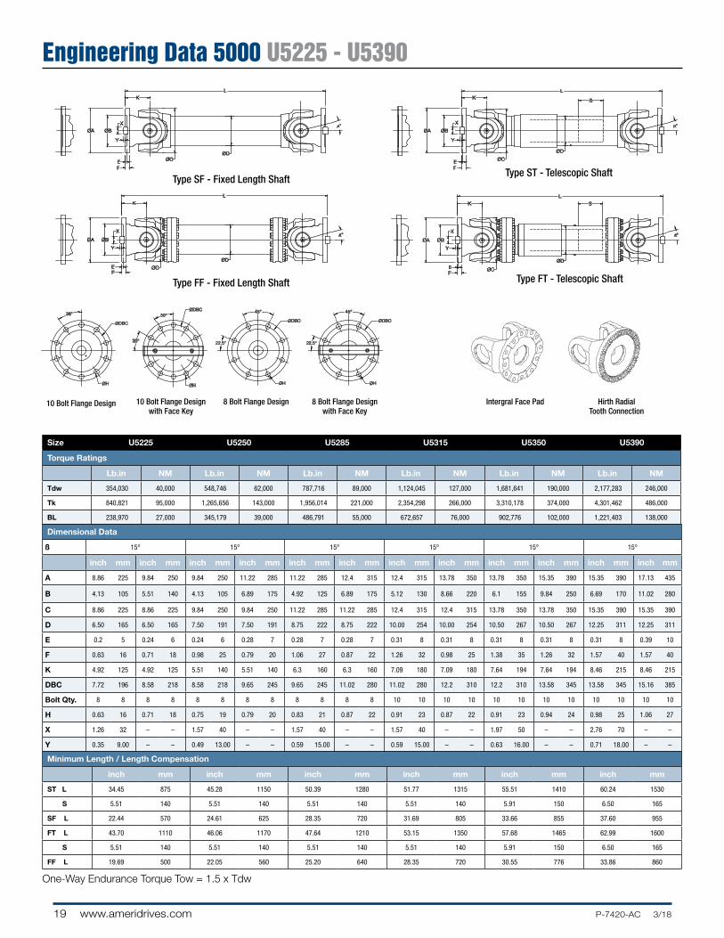
Engineering Data 5000 U5225 - U5390
One-Way Endurance Torque Tow = 1.5 x Tdw
Type FF - Fixed Length Shaft Type FT - Telescopic Shaft
45°
22.5°
ØH
ØDBC
45°
22.5°
ØH
ØDBC
ØH
ØDBC
ØH
ØDBC
36°
30°
30°
ØC
K
L
S
EF
ØBØA
X
Y
ØC
K
L
EF
ØBØA
X
Y
ØC
LK S
ØA ØB
FE
X
Y
ØC
LK
ØA ØB
FE
X
Y
°
ØD
ØD
ØD
ØD
°
°
°
45°
22.5°
ØH
ØDBC
45°
22.5°
ØH
ØDBC
ØH
ØDBC
ØH
ØDBC
36°
30°
30°
ØC
K
L
S
EF
ØBØA
X
Y
ØC
K
L
EF
ØBØA
X
Y
ØC
LK S
ØA ØB
FE
X
Y
ØC
LK
ØA ØB
FE
X
Y
°
ØD
ØD
ØD
ØD
°
°
°
45°
22.5°
ØH
ØDBC
45°
22.5°
ØH
ØDBC
ØH
ØDBC
ØH
ØDBC
36°
30°
30°
ØC
K
L
S
EF
ØBØA
X
Y
ØC
K
L
EF
ØBØA
X
Y
ØC
LK S
ØA ØB
FE
X
Y
ØC
LK
ØA ØB
FE
X
Y
°
ØD
ØD
ØD
ØD
°
°
°
45°
22.5°
ØH
ØDBC
45°
22.5°
ØH
ØDBC
ØH
ØDBC
ØH
ØDBC
36°
30°
30°
ØC
K
L
S
EF
ØBØA
X
Y
ØC
K
L
EF
ØBØA
X
Y
ØC
LK S
ØA ØB
FE
X
Y
ØC
LK
ØA ØB
FE
X
Y
°
ØD
ØD
ØD
ØD
°
°
°
10 Bolt Flange Design
45°
22.5°
ØH
ØDBC
45°
22.5°
ØH
ØDBC
ØH
ØDBC
ØH
ØDBC
36°
30°
30°
ØC
K
L
S
EF
ØBØA
X
Y
ØC
K
L
EF
ØBØA
X
Y
ØC
LK S
ØA ØB
FE
X
Y
ØC
LK
ØA ØB
FE
X
Y
°
ØD
ØD
ØD
ØD
°
°
°
8 Bolt Flange Design
45°
22.5°
ØH
ØDBC
45°
22.5°
ØH
ØDBC
ØH
ØDBC
ØH
ØDBC
36°
30°
30°
ØC
K
L
S
EF
ØBØA
X
Y
ØC
K
L
EF
ØBØA
X
Y
ØC
LK S
ØA ØB
FE
X
Y
ØC
LK
ØA ØB
FE
X
Y
°
ØD
ØD
ØD
ØD
°
°
°
8 Bolt Flange Designwith Face Key
45°
22.5°
ØH
ØDBC
45°
22.5°
ØH
ØDBC
ØH
ØDBC
ØH
ØDBC
36°
30°
30°
ØC
K
L
S
EF
ØBØA
X
Y
ØC
K
L
EF
ØBØA
X
Y
ØC
LK S
ØA ØB
FE
X
Y
ØC
LK
ØA ØB
FE
X
Y
°
ØD
ØD
ØD
ØD
°
°
°
10 Bolt Flange Designwith Face Key
45°
22.5°
ØH
ØDBC
45°
22.5°
ØH
ØDBC
ØH
ØDBC
ØH
ØDBC
36°
30°
30°
ØC
K
L
S
EF
ØBØA
X
Y
ØC
K
L
EF
ØBØA
X
Y
ØC
LK S
ØA ØB
FE
X
Y
ØC
LK
ØA ØB
FE
X
Y
°
ØD
ØD
ØD
ØD
°
°
°
Intergral Face Pad Hirth Radial Tooth Connection
Type SF - Fixed Length ShaftType ST - Telescopic Shaft
Size U5225 U5250 U5285 U5315 U5350 U5390
Torque Ratings
Lb.in NM Lb.in NM Lb.in NM Lb.in NM Lb.in NM Lb.in NM
Tdw 354,030 40,000 548,746 62,000 787,716 89,000 1,124,045 127,000 1,681,641 190,000 2,177,283 246,000
Tk 840,821 95,000 1,265,656 143,000 1,956,014 221,000 2,354,298 266,000 3,310,178 374,000 4,301,462 486,000
BL 238,970 27,000 345,179 39,000 486,791 55,000 672,657 76,000 902,776 102,000 1,221,403 138,000
Dimensional Data
ß 15° 15° 15° 15° 15° 15°
inch mm inch mm inch mm inch mm inch mm inch mm inch mm inch mm inch mm inch mm inch mm inch mm
A 8.86 225 9.84 250 9.84 250 11.22 285 11.22 285 12.4 315 12.4 315 13.78 350 13.78 350 15.35 390 15.35 390 17.13 435
B 4.13 105 5.51 140 4.13 105 6.89 175 4.92 125 6.89 175 5.12 130 8.66 220 6.1 155 9.84 250 6.69 170 11.02 280
C 8.86 225 8.86 225 9.84 250 9.84 250 11.22 285 11.22 285 12.4 315 12.4 315 13.78 350 13.78 350 15.35 390 15.35 390
D 6.50 165 6.50 165 7.50 191 7.50 191 8.75 222 8.75 222 10.00 254 10.00 254 10.50 267 10.50 267 12.25 311 12.25 311
E 0.2 5 0.24 6 0.24 6 0.28 7 0.28 7 0.28 7 0.31 8 0.31 8 0.31 8 0.31 8 0.31 8 0.39 10
F 0.63 16 0.71 18 0.98 25 0.79 20 1.06 27 0.87 22 1.26 32 0.98 25 1.38 35 1.26 32 1.57 40 1.57 40
K 4.92 125 4.92 125 5.51 140 5.51 140 6.3 160 6.3 160 7.09 180 7.09 180 7.64 194 7.64 194 8.46 215 8.46 215
DBC 7.72 196 8.58 218 8.58 218 9.65 245 9.65 245 11.02 280 11.02 280 12.2 310 12.2 310 13.58 345 13.58 345 15.16 385
Bolt Qty. 8 8 8 8 8 8 8 8 8 8 8 8 10 10 10 10 10 10 10 10 10 10 10 10
H 0.63 16 0.71 18 0.75 19 0.79 20 0.83 21 0.87 22 0.91 23 0.87 22 0.91 23 0.94 24 0.98 25 1.06 27
X 1.26 32 – – 1.57 40 – – 1.57 40 – – 1.57 40 – – 1.97 50 – – 2.76 70 – –
Y 0.35 9.00 – – 0.49 13.00 – – 0.59 15.00 – – 0.59 15.00 – – 0.63 16.00 – – 0.71 18.00 – –
Minimum Length / Length Compensation
inch mm inch mm inch mm inch mm inch mm inch mm
ST L 34.45 875 45.28 1150 50.39 1280 51.77 1315 55.51 1410 60.24 1530
S 5.51 140 5.51 140 5.51 140 5.51 140 5.91 150 6.50 165
SF L 22.44 570 24.61 625 28.35 720 31.69 805 33.66 855 37.60 955
FT L 43.70 1110 46.06 1170 47.64 1210 53.15 1350 57.68 1465 62.99 1600
S 5.51 140 5.51 140 5.51 140 5.51 140 5.91 150 6.50 165
FF L 19.69 500 22.05 560 25.20 640 28.35 720 30.55 776 33.86 860

P-7420-AC 3/18 www.ameridrives.com 20
Engineering Data 5000 U5440 - U5800
Size U5440 U5490 U5550 U5620 U5720 U5760 U5800
Torque Ratings
Lb.in NM Lb.in NM Lb.in NM Lb.in NM Lb.in NM Lb.in NM Lb.in NM
Tdw 3,389,835 383,000 4,487,327 507,000 6,611,506 747,000 9,850,878 1,113,000 15,772,026 1,782,000 17,763,444 2,007,000 22,702,159 2,565,000
Tk 6,682,312 755,000 8,841,893 999,000 13,045,997 1,474,000 19,462,786 2,199,000 31,119,217 3,516,000 35,031,245 3,958,000 44,784,766 5,060,000
BL 1,876,358 212,000 2,566,716 290,000 3,566,850 403,000 5,044,924 570,000 7,726,700 873,000 8,930,401 1,009,000 10,302,266 1,164,000
Dimensional Data
ß 10º 10º 10º 10º 10º 10º 10º
inch mm inch mm inch mm inch mm inch mm inch mm inch mm
A 17.13 435 18.90 480 21.65 550 24.41 620 28.35 720 29.92 760 31.50 800
C 17.32 440 19.29 490 21.65 550 24.41 620 28.35 720 29.92 760 31.50 800
D 14.00 356 14.02 356 16.50 419 21.54 547 22.01 559 24.02 610 24.02 610
F 1.69 42.9 1.75 44.5 2.00 50.8 2.12 53.8 2.25 57.2 2.38 60.5 2.50 63.5
K 10.24 260 10.63 270 12.01 305 13.39 340 16.44 417.6 17.35 440.7 18.27 464.1
Minimum Length / Length Compensation
inch mm inch mm inch mm inch mm inch mm inch mm inch mm
ST L 64.57 1640 68.50 1740 77.56 1970 83.86 2130 95.67 2430 100.00 2540 108.27 2750
S 7.52 191 7.52 191 9.49 241 9.49 241 10.00 254 10.98 279 10.98 279
SF L 44.49 1130 46.06 1170 52.36 1330 57.87 1470 70.47 1790 74.41 1890 78.35 1990
FT L 73.82 1875 78.35 1990 90.55 2300 95.47 2425 108.27 2750 113.78 2890 117.32 2980
S 7.52 191 7.52 191 9.49 241 9.49 241 10.00 254 10.98 279 10.98 279
FF L 40.94 1040 42.52 1080 48.03 1220 53.54 1360 65.75 1670 69.41 1763 73.07 1856
One-Way Endurance Torque Tow = 1.5 x Tdw
Type FF - Fixed Length ShaftType FT - Telescopic Shaft
Type SF - Fixed Length Shaft Type ST - Telescopic Shaft
ØA
K
L
ØD
ØC
K
L
ØD
ØC
K
L
ØC
K
L
ØC
ØD
S
ØD
S
F
F
F
F
ØA
ØA
ØA
Face Key Intergral Face Pad Hirth Radial Tooth Connection
ØA
K
L
ØD
ØC
K
L
ØD
ØC
K
L
ØC
K
L
ØC
ØD
S
ØD
S
F
F
F
F
ØA
ØA
ØA
ØA
K
L
ØD
ØC
K
L
ØD
ØC
K
L
ØC
K
L
ØC
ØD
S
ØD
S
F
F
F
F
ØA
ØA
ØA
ØA
K
L
ØD
ØC
K
L
ØD
ØC
K
L
ØC
K
L
ØC
ØD
S
ØD
S
F
F
F
F
ØA
ØA
ØA
21 www.ameridrives.com P-7420-AC 3/18
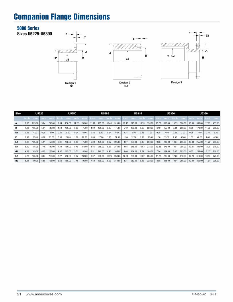
Companion Flange Dimensions5000 SeriesSizes U5225-U5390 F
E1
E1
E1F
B
A
d1D1
B
B
A
d2
To Suit
A
Design 1SF
Design 2SLF
Design 3
FE1
E1
E1F
B
A
d1D1
B
B
A
d2
To Suit
A
Design 1SF
Design 2SLF
Design 3
FE1
E1
E1F
B
A
d1D1
B
B
A
d2
To Suit
A
Design 1SF
Design 2SLF
Design 3
Size U5225 U5250 U5285 U5315 U5350 U5390
inch mm inch mm inch mm inch mm inch mm inch mm inch mm inch mm inch mm inch mm inch mm inch mm
A 8.86 225.00 9.84 250.00 9.84 250.00 11.22 285.00 11.22 285.00 12.40 315.00 12.40 315.00 13.78 350.00 13.78 350.00 15.35 390.00 15.35 390.00 17.13 435.00
B 4.13 105.00 5.51 140.00 4.13 105.00 6.89 175.00 4.92 125.00 6.89 175.00 5.12 130.00 8.66 220.00 6.10 155.00 9.84 250.00 6.69 170.00 11.02 280.00
E1 0.16 4.00 0.20 5.00 0.20 5.00 0.24 6.00 0.24 6.00 0.24 6.00 0.24 6.00 0.28 7.00 0.28 7.00 0.28 7.00 0.28 7.00 0.35 9.00
F 0.98 25.00 0.98 25.00 0.98 25.00 1.06 27.00 1.06 27.00 1.26 32.00 1.26 32.00 1.38 35.00 1.38 35.00 1.57 40.00 1.57 40.00 1.65 42.00
L1 4.92 125.00 5.91 150.00 5.91 150.00 6.89 175.00 6.89 175.00 8.07 205.00 8.07 205.00 9.06 230.00 9.06 230.00 10.04 255.00 10.04 255.00 11.22 285.00
D1 6.10 155.00 7.48 190.00 7.48 190.00 8.46 215.00 8.46 215.00 9.65 245.00 9.65 245.00 10.83 275.00 10.83 275.00 12.01 305.00 12.01 305.00 12.20 310.00
d1 4.13 105.00 4.92 125.00 4.92 125.00 5.51 140.00 5.51 140.00 6.46 164.00 6.46 164.00 7.24 184.00 7.24 184.00 8.07 205.00 8.07 205.00 8.27 210.00
L2 7.28 185.00 8.27 210.00 8.27 210.00 9.37 238.00 9.37 238.00 10.24 260.00 10.24 260.00 11.22 285.00 11.22 285.00 12.20 310.00 12.20 310.00 10.83 275.00
d2 5.91 150.00 6.50 165.00 6.50 165.00 7.48 190.00 7.48 190.00 8.27 210.00 8.27 210.00 8.98 228.00 8.98 228.00 10.04 255.00 10.04 255.00 11.61 295.00

P-7420-AC 3/18 www.ameridrives.com 22
Wing Bearing C-Series
Size 2C 3C 4C 5C 6C 7C
Torque Ratings
Lb.in Nm Lb.in Nm Lb.in Nm Lb.in Nm Lb.in Nm Lb.in Nm
Tdw 7,200 813 10,200 1,152 12,720 1,437 18,000 2,034 22,980 2,596 37,200 4,203
Tk 8,880 1,003 14,016 1,584 17,676 1,997 22,476 2,539 29,256 3,305 49,908 5,639
BL 3,156 357 5,052 571 6,324 715 10,740 1,213 14,544 1,643 19,596 2,214
Dimensional Data (inches and millimeters except where noted)
ß 20° 20° 25° 15° 30° 20°
inch mm inch mm inch mm inch mm inch mm inch mm
A 0.52 13.21 0.61 15.95 0.61 15.95 0.69 17.53 0.69 17.53 0.81 20.57
B 3.34 84.84 3.81 96.77 4.50 114.30 4.78 121.41 5.84 148.34 6.22 157.99
Minimum Length / Length Compensation
Z (ST) 10.80 274.32 12.20 309.88 12.20 309.88 13.76 349.50 15.02 381.51 16.74 425.20
Z1 (SC) 8.42 213.87 9.30 236.22 9.30 236.22 11.26 286.00 12.39 314.71 14.24 361.70
C (ST) 2.00 50.80 2.00 50.80 2.00 50.80 3.00 76.20 3.00 76.20 3.00 76.20
C1 (SC) 1.50 38.10 1.50 38.10 1.50 38.10 1.50 38.10 1.50 38.10 2.00 50.80
Size 8C 8.5C 9C 10C 10.5C 11C 15C
Torque Ratings
Lb.in Nm Lb.in Nm Lb.in Nm Lb.in Nm Lb.in Nm Lb.in Nm Lb.in Nm
Tdw 57,000 6,440 83,400 9,423 108,000 12,202 178,800 20,202 180,000 20,337 234,000 26,438 240,000 27,116
Tk 86,700 9,796 98,268 11,103 161,136 18,206 202,320 22,859 298,800 33,760 312,456 35,303 354,120 40,010
BL 29,124 3,291 29,700 3,356 46,728 5,280 72,216 8,159 80,928 9,144 111,276 12,573 168,840 19,076
Dimensional Data (inches and millimeters except where noted)
ß 20° 25° 15° 30° 25° 25° 25°
inch mm inch mm inch mm inch mm inch mm inch mm inch mm
A 0.81 20.57 1.00 25.40 1.00 25.40 1.28 32.51 1.34 34.04 1.58 40.13 1.50 38.10
B 8.50 157.99 6.88 174.75 8.63 219.20 8.88 225.55 9.12 231.65 9.25 234.95 10.75 273.05
Minimum Length / Length Compensation
Z (ST) 16.74 425.2 18.25 463.55 18.25 463.55 20.62 523.75 28.38 720.85 30.32 770.13 30.60 777.24
Z1 (SC) 14.24 361.7 15.63 397.00 15.63 397.00 17.87 453.90 23.50 596.90 25.00 635.00 24.75 628.65
C (ST) 3.00 76.20 3.00 76.20 3.00 76.20 3.00 76.20 5.00 127.00 5.00 127.00 5.00 127.00
C1 (SC) 2.00 50.80 2.00 50.80 2.00 50.80 2.00 50.80 2.00 50.80 2.00 50.80 2.00 50.80
One-Way Endurance Torque Tow = 1.5 x Tdw

23 www.ameridrives.com P-7420-AC 3/18
Wing Bearing J-Series
S
THD
W
B
A
G
20° 20°
Type ST with tube and inverted, large diameter slip spline
(standard maximum working angle: 20°, except J-600: 17.5°)
Shortest length face to face ofbearings for 15° angle
Shortest length face to face ofbearings for 7° angle
End view for all types
P-Hole SizeQ-Bolt Size
T3H
15°15°
B A
T4H
7°7°7°7°
D
RR
Type “CP” with coupling and without slip —TTclose-coupled (standard maximum working angle: 15°)
Type “CP7” with coupling plate and without slip —TTextra-close-coupled (standard maximum working angle: 7°)
B A
D
M
N
JK
L
S
T*HD
GW
20°20°
B
AR
Type STwith tube and slip
(standard maximum working angle: 20°)
* Minimum compressed length face to face of bearings with shortest tube
* Compressed length face to face of bearings of typical assembly * Fixed length face to face of bearings.Minimum �xed length face to face of bearings with shortest tube
Type SC with slip and without tube – close-coupled
(standard maximum working angle: 20°)
Type T with tube and without slip
(standard maximum working angle: 20°)
T1*HD D
R
SG1
20° 20°20° 20°
B A
T2*H
W
B A
S
THD
W
B
A
G
20° 20°
Type ST with tube and inverted, large diameter slip spline
(standard maximum working angle: 20°, except J-600: 17.5°)
Shortest length face to face ofbearings for 15° angle
Shortest length face to face ofbearings for 7° angle
End view for all types
P-Hole SizeQ-Bolt Size
T3H
15°15°
B A
T4H
7°7°7°7°
D
RR
Type “CP” with coupling and without slip —TTclose-coupled (standard maximum working angle: 15°)
Type “CP7” with coupling plate and without slip —TTextra-close-coupled (standard maximum working angle: 7°)
B A
D
M
N
JK
L
J-170-ST - J-130-ST
J-490-ST - J-1200-ST

P-7420-AC 3/18 www.ameridrives.com 24
Wing Style J Series
Size J170 J230 J310 J490 J600 J800 J1200
Torque Ratings
Lb.in Nm Lb.in Nm Lb.in Nm Lb.in Nm Lb.in Nm Lb.in Nm Lb.in Nm
Tdw 40,800 4,610 58,560 6,616 80,400 9,084 120,000 13,558 144,960 16.378 174,000 19,659 249,600 28,201
Tk 51,000 5,762 73,200 8,270 100,800 11,389 150,000 16,948 181,200 20,473 216,000 24,405 312,000 35,251
BL 33,000 3,729 45,972 5,194 62,820 7,098 97,824 11,053 118,824 13,425 160,044 18,083 240,060 27,123
Dimensional Data
ß (ST, SF & SC)
20° 20° 20° 20° 20° 20° 20°
ß (CP) 15° 15° 15° 15° 15° 15° 15°
ß (CP7) 7° 7° 7° 7° 7° 7° 7°
inch mm inch mm inch mm inch mm inch mm inch mm inch mm
A 6.75 171.45 6.88 174.75 8.62 218.95 9.25 234.95 9.25 234.95 10.75 273.05 12.18 309.37
B 6.375 161.93 6.500 165.10 8.250 209.55 8.750 222.25 8.750 222.25 10.236 259.99 11.500 292.10
D 0.92 23.4 1.11 28.19 1.11 28.19 1.34 34.04 1.58 40.13 1.50 38.10 1.78 45.21
H 0.20 5.08 0.20 5.08 0.20 5.08 0.34 8.64 0.34 8.64 0.44 11.18 0.44 11.18
W 2 3/8-16 2 3/8-16 3.0-16 5.0-29 5.0-29 5 43/64-33 5 43/64-33
S 0.120 3.05 0.148 3.76 0.220 5.59 0.253 6.43 0.276 7.01 0.340 8.64 0.340 8.64
J 2.440 61.98 2.812 71.42 2.812 71.42 3.500 88.90 3.500 88.90 3.936 99.97 4.640 117.86
K 1.220 30.99 1.406 35.71 1.406 35.71 1.750 44.45 1.750 44.45 1.968 49.99 2.320 58.93
L 0.6235 15.84 0.6235 15.84 0.6235 15.84 0.9985 25.36 0.9985 25.36 1.2485 31.71 1.2485 31.71
M 4.930 125.22 4.874 123.80 6.624 168.25 6.800 172.72 6.800 172.72 7.872 199.95 8.880 225.55
N 2.465 62.61 2.437 61.90 3.312 84.12 3.400 86.36 3.400 86.36 3.936 99.97 4.440 112.78
P 15/32 11.91 17/32 13.49 17/32 13.49 21/32 16.67 25/32 19.84 25/32 19.84 29/32 23.02
Q 7/16-20 1/2-20 1/2-20 5/8-18 3/4-16 3/4-16 7/8-14
Minimum Length / Length Compensation1
T (ST) 18.06 458.72 21.75 552.45 24.50 622.30 25.66 651.76 26.04 661.42 30.25 768.35 32.37 822.2
T1 (SC) -- -- 14.44 366.78 12.00 304.80 18.62 472.95 21.00 533.40 23.56 598.42 21.62 549.15
T2 (SF) 9.80 248.92 13.12 333.25 13.12 333.25 13.98 355.09 12.94 328.68 17.31 439.67 20.00 508.00
T3 (CP) -- -- 6.50 165.10 7.00 177.80 -- -- -- -- -- -- -- --
T4 (CP7) 5.52 140.21 6.00 152.40 6.00 152.40 7.68 195.07 -- -- 9.67 245.62 -- --
G (ST) 3.00 76.20 3.00 76.20 5.00 127.00 5.00 127.00 4.00 101.60 5.00 127.00 5.00 127.00
G1 (SC) -- -- 2.00 50.80 1.25 31.75 2.75 69.85 2.50 63.50 4.00 101.60 1.00 25.40
A Swing Diameter M Bolt Hole Spread Across YokeB Pilot Diameter of Mating Part N Bolt Hole Location From Center LineD Bearing Height P Bolt Hole DiameterG Slip Q Bolt Size H Height of Key R Outside Tube DiameterJ Bolt Hole Spread Across Bearing Wings S Tube Wall ThicknessK Bolt Hole Location from Center Line T Compressed or Fixed Length Face to Face of BearingsL Key Width of Mating Part
One-Way Endurance Torque Tow = 1.5 x Tdw

25 www.ameridrives.com P-7420-AC 3/18
Fitting Yokes J-Series
F
EA
CD
G
H EA
DC
G
Cast YokeForged Yoke with Straight Bore and Keyway
Size J170 J230 J310 J490 J600 J1200
DESIGN 1 YOKE
inch mm inch mm inch mm inch mm inch mm inch mm
A (min) 1.38 35.05 1.50 38.10 1.50 38.10 2.25 57.15 2.25 57.15 2.25 57.15
A (max) 2.68 38.07 3.14 79.76 3.42 86.87 4.10 104.14 4.70 119.38 5.03 127.76
C 4.68 118.87 4.75 120.65 6.56 166.62 6.16 156.46 6.16 156.46 8.25 209.55
D 3.43 87.12 3.31 84.07 4.94 125.48 4.54 115.32 4.54 115.32 6.00 152.40
F 2 50.8 2.50 63.50 3.50 88.90 3.25 82.55 3.25 82.55 5.00 127.00
G 1.25 31.75 1.44 36.58 1.62 41.15 1.62 41.15 1.62 41.15 2.25 57.15
H 3.25 82.55 3.50 88.90 4.00 101.60 4.88 123.95 4.88 123.95 -- --
DESIGN 2 YOKE
A (min) 2.75 69.85 2.00 50.80 3.25 82.55 3.88 98.55 4.00 101.60 4.50 114.30
A (max) 4.02 102.11 4.02 102.11 5.20 132.08 5.50 139.70 5.50 139.70 7.04 178.82
C 5.19 131.83 5.36 136.14 6.56 166.62 6.80 172.72 6.80 172.72 10.00 254.00
D 4 101.6 4.00 101.60 5.00 127.00 5.00 127.00 5.00 127.00 7.85 199.39
F -- -- -- -- -- -- -- -- -- -- -- --
G 1.19 30.23 1.36 34.54 1.56 39.62 1.80 45.72 1.80 45.72 2.15 54.61
H -- -- -- -- -- -- -- -- -- -- -- --
Design 1 Design 2

P-7420-AC 3/18 www.ameridrives.com 26
WeightsUniversal Joint Weights at Minimum Length (pounds)
SIZEFlange Dia.
(Inches)
TYPETube
(Inches)ST SF FTFF
With Spacer
FF Without
Spacer
U2131 3.88 14 12 – – – 0.18
U2135 4.63 25 20 – – – 0.22
U2141 4.63 25 20 – – – 0.25
U2148 5.88 27 22 – – – 0.25
U2155 5.88 37 34 – – – 0.29
U2160 6.88 45 36 – – – 0.9
U2170 8 68 55 – – – 0.46
U2180 8 99 83 – – – 0.52
U2188 9.63 152 122 – – – 0.98
U2192 9.63 166 166 – – – 1
U3200 8.86 288 214 299 252 178 1.78
U3225 9.84 296 222 345 291 194 1.78
U3250 8.86 362 239 426 352 259 2.22
U3285 9.84 370 247 470 391 275 2.22
U3315 9.84 474 291 579 436 335 2.67
U3350 11.22 483 300 617 466 353 2.67
U3390 11.22 714 446 786 564 445 3.22
U3440 12.4 729 461 842 610 475 3.22
U3490 12.4 1,000 648 1,099 801 639 3.67
U3550 13.78 1,020 668 1,172 866 679 3.67
U3620 13.78 1,354 867 1,490 1,056 882 4.22
27 www.ameridrives.com P-7420-AC 3/18
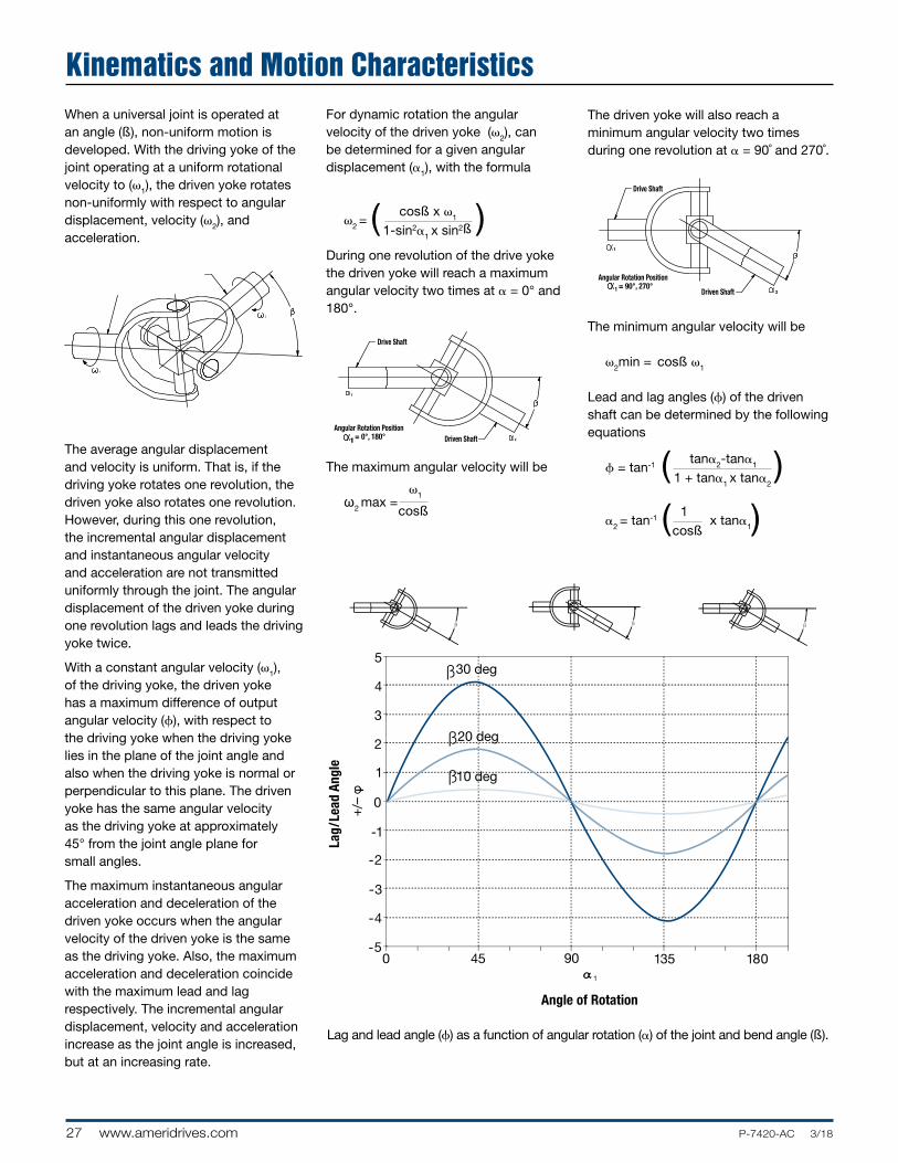
Kinematics and Motion CharacteristicsWhen a universal joint is operated at an angle (ß), non-uniform motion is developed. With the driving yoke of the joint operating at a uniform rotational velocity to (ω1), the driven yoke rotates non-uniformly with respect to angular displacement, velocity (ω2), and acceleration.
The average angular displacement and velocity is uniform. That is, if the driving yoke rotates one revolution, the driven yoke also rotates one revolution. However, during this one revolution, the incremental angular displacement and instantaneous angular velocity and acceleration are not transmitted uniformly through the joint. The angular displacement of the driven yoke during one revolution lags and leads the driving yoke twice.
With a constant angular velocity (ω1), of the driving yoke, the driven yoke has a maximum difference of output angular velocity (ϕ), with respect to the driving yoke when the driving yoke lies in the plane of the joint angle and also when the driving yoke is normal or perpendicular to this plane. The driven yoke has the same angular velocity as the driving yoke at approximately 45° from the joint angle plane for small angles.
The maximum instantaneous angular acceleration and deceleration of the driven yoke occurs when the angular velocity of the driven yoke is the same as the driving yoke. Also, the maximum acceleration and deceleration coincide with the maximum lead and lag respectively. The incremental angular displacement, velocity and acceleration increase as the joint angle is increased, but at an increasing rate.
The driven yoke will also reach a minimum angular velocity two times during one revolution at α = 90˚ and 270˚.
The minimum angular velocity will be
ω2min = cosß ω1
Lead and lag angles (ϕ) of the driven shaft can be determined by the following equations
ϕ = tan-1 ( tanα2-tanα1 ) 1 + tanα1 x tanα2
α2 = tan-1 ( 1 x tanα1)
cosß
1
2
Drive Shaft
Driven ShaftAngular Rotation Position
= 0°, 180°
CAT17
1
1
2
CAT18
1
2
Drive Shaft
Driven Shaft
Angular Rotation Position = 90°, 270°1
Lag/
Lead
Ang
le
Angle of Rotation
20 deg
10 deg
30 deg5
4
3
2
1
0
-1
-2
-3
-4
-50 45 90 135 180
1
+ /–
Lag and lead angle (ϕ) as a function of angular rotation (α) of the joint and bend angle (ß).
For dynamic rotation the angular velocity of the driven yoke (ω2), can be determined for a given angular displacement (α1), with the formula
ω2 = ( cosß x ω1 ) 1-sin2α1 x sin2ß
During one revolution of the drive yoke the driven yoke will reach a maximum angular velocity two times at α = 0° and 180°.
The maximum angular velocity will be
ω2 max = ω1
cosß

P-7420-AC 3/18 www.ameridrives.com 28
Kinematics and Motion Characteristics
Velocity variation (U) is a means for comparison of the angular velocities of the drive and driven shafts. Velocity variation (U) is calculated using the formula
U = (ω2max-ω2min) = tanß x sinß ω1
As a result of the non-uniform motion of a universal joint, few applications are suitable for a single universal joint. However, by placing two universal joints in tandem the irregularities of a single joint can be compensated. By arranging the two universal joints in either a “Z” or “W” bend configuration with joint angles ß1 and ß2, equal, the velocity variations developed in the first joint are in effect cancelled by the velocity variations in the second joint.
Z Bend
W Bend
Z Bend
W Bend
Synchronous rotation of the drive and driven shafts is possible provided that all three of the following conditions are met:
1. The axis of all shaft sections lie in the same plane.
2. The bearing bores of the inboard yokes of the center section lie in the same plane.
3. The bend angles ß1 and ß2 are equal.
This ideal or phased arrangement will result in homokinetic operation of the universal joint driveline assembly. Failure to meet one or more of these requirements will result in some level of velocity fluctuation in the driven shaft. The acceptability of this velocity fluctuation is a function of the speed, system mass and the sensitivity of the application.

29 www.ameridrives.com P-7420-AC 3/18
Bore Tolerances
Recommended Bore Tolerances• Recommended standard bore
tolerances for interference fits are shown in table (right).
• Bore tolerances conform to AGMA 9002-A86 standards.
Interference FitsUnless specified, bores will be furnished with an interference fit.
When shaft sizes only are stated on order and they consist of fractional or decimal dimensions without tolerance, the bore will be sized for an interference fit in accordance with table (right). If exact shaft size and tolerance do not agree with tables, the smallest shaft dimension will be considered “basic” and the standard negative bore tolerance will be applied.
Example: Interference Fit
Shaft Size – 2.000 (Basic Size) 1.999 (With Tolerance)
Bore Size – 1.999 1.998
Interference Fit (Inches)
Nominal Bore SizeShaft Tolerance Bore Tolerance Interference Range
Over Thru
0.0000 / 1.5000 +.0000 / -.0005 –.0005 / –.0010 –.0000 / –.0010
1.5000 / 3.0000
+.0000 / -.0010
–.0010 / –.0020 –.0000 / –.0020
3.0000 / 4.0000 –.0015 / –.0030 –.0005 / –.0030
4.0000 / 5.0000 –.0020 / –.0035 –.0010 / –.0035
5.0000 / 7.0000 –.0025 / –.0040 –.0015 / –.0040
7.0000 / 8.0000 –.0030 / –.0050 –.0020 / –.0050
8.0000 / 9.0000 –.0035 / –.0055 –.0025 / –.0055
9.0000 / 10.0000 –.0040 / –.0060 –.0030 / –.0060
10.0000 / 11.0000 –.0045 / –.0065 –.0035 / –.0065
11.0000 / 12.0000 –.0050 / –.0070 –.0040 / –.0070
12.0000 / 13.0000 –.0055 / –.0075 –.0045 / –.0075
13.0000 / 14.0000 –.0060 / –.0080 –.0050 / –.0080
14.0000 / 15.0000 –.0065 / –.0085 –.0055 / –.0085
15.0000 / 16.0000 –.0065 / –.0090 –.0055 / –.0090
16.0000 / 17.0000 –.0070 / –.0095 –.0060 / –.0095
17.0000 / 18.0000 –.0075 / –.0100 –.0065 / –.0100
18.0000 / 19.0000 –.0080 / –.0105 –.0070 / –.0105
19.0000 / 20.0000 –.0085 / –.0110 –.0075 / –.0110
20.0000 / 22.0000
+.0000 / -.0020
–.0100 / –.0130 –.0080 / –.0130
22.0000 / 24.0000 –.0110 / –.0140 –.0090 / –.0140
24.0000 / 26.0000 –.0120 / –.0150 –.0100 / –.0150
Standard Recommended Keyways (Inches)
Nominal Bore Size Keyway
Over Thru Width Depth Sq. Key Depth Red. Key
.312 / .438 .094 .047 –
.438 / .562 .125 .063 .047
.562 / .875 .188 .094 .062
.875 / 1.250 .250 .125 .094
1.250 / 1.375 .312 .156 .125
1.375 / 1.750 .375 .188 .125
1.750 / 2.250 .500 .250 .188
2.250 / 2.750 .625 .313 .219
2.750 / 3.250 .750 .375 .250
3.250 / 3.750 .875 .438 .313
3.750 / 4.500 1.000 .500 .375
4.500 / 5.500 1.250 .625 .438
5.500 / 6.500 1.50 .750 .500
6.500 / 7.500 1.75 .875 .750
7.500 / 9.000 2.000 1.00 .750
9.000 / 11.000 2.500 1.250 .875
11.000 / 13.000 3.000 1.500 1.000
13.000 / 15.000 3.500 1.750 1.250
15.000 / 18.000 4.000 – 1.500
18.000 / 22.000 5.000 – 1.750
22.000 / 26.000 6.000 – 2.000

Altra Industrial Motion
The Brands of Altra Industrial Motion
Couplings
Ameridriveswww.ameridrives.com
Bibby Turbo� ex www.bibbyturbo� ex.com
Guardian Couplingswww.guardiancouplings.com
Hucowww.huco.com
Lami� ex Couplingswww.lami� excouplings.com
Stromag www.stromag.com
TB Wood’swww.tbwoods.com
Geared Cam Limit Switches
Stromagwww.stromag.com
Electric Clutches & Brakes
Inertia Dynamicswww.idicb.com
Matrixwww.matrix-international.com
Stromagwww.stromag.com
Warner Electricwww.warnerelectric.com
Linear Products
Warner Linearwww.warnerlinear.com
Engineered Bearing Assemblies
Kilianwww.kilianbearings.com
Heavy Duty Clutches & Brakes
Industrial Clutchwww.indclutch.com
Twi� exwww.twi� ex.com
Stromagwww.stromag.com
Svendborg Brakeswww.svendborg-brakes.com
Wichita Clutchwww.wichitaclutch.com
Belted Drives
TB Wood’s www.tbwoods.com
Gearing
Bauer Gear Motorwww.bauergears.com
Boston Gearwww.bostongear.com
Delroyd Worm Gearwww.delroyd.com
Nuttall Gearwww.nuttallgear.com
Overrunning Clutches
Formsprag Clutchwww.formsprag.com
Marland Clutchwww.marland.com
Stieberwww.stieberclutch.com
Ameridrives Facilities
North America
1802 Pittsburgh AvenueErie, PA 16502 - USA814-480-5000
Mill Spindles, Amerifl ex, Ameridisc, Universal Joints, Driveshafts, Mill Gear Couplings
2000 Clovis Barker RoadSan Marcos, TX 78666 - USA888-449-9439
Gear Couplings, Small Industrial Driveshafts
300 Indiana Highway 212Michigan City, IN 46360219-874-5248
Irrigation Universal Driveshafts
Neither the accuracy nor completeness of the information contained in this publication is guaranteed by the company and may be subject to change in its sole discretion. The operating and performance characteristics of these products may vary depending on the application, installation, operating conditions and environmental factors. The company’s terms and conditions of sale can be viewed at http://www.altramotion.com/terms-and-conditions/sales-terms-and-conditions. These terms and conditions apply to any person who may buy, acquire or use a product referred to herein, including any person who buys from a licensed distributor of these branded products.
©2018 by Ameridrives LLC. All rights reserved. All trademarks in this publication are the sole and exclusive property of Ameridrives LLC or one of its af� liated companies.
www.ameridrives.com P-7420-AC 3/18