Embed Size (px)
Citation preview

Part Number 02250058---882eSullair Corporation
INDUSTRIAL AIRCOMPRESSOR
OPERATOR’S
LS---12 & LS---1640, 50, 60, 75 & 100HP
STANDARD & 24 KT(30, 37, 45, 55 & 75KW)
MANUAL ANDPARTS LIST
(U.S.A.)
KEEP FORFUTURE
REFERENCE
AIR CARESEMINAR TRAINING
Sullair Air Care Seminars are 3---day courses that provide hands---on instructionin the proper operation, maintenance and service of Sullair equipment.Individual seminars on Industrial compressors and compressor electricalsystems are presented at regular intervals throughout the year at a dedicatedtraining facility at Sullair’s corporate headquarters in Michigan City, Indiana.
Instruction includes discussion of the function and installation of Sullair serviceparts, troubleshooting of the most common problems, and actual equipmentoperation. The seminars are recommended for maintenance and servicepersonnel.
For detailed course outlines, schedule and cost information contact:
Sullair Corporate Training Department1---800---SULLAIR or 219---879---5451 (ext. 1816)
--- Or Write ---Sullair Corporation3700 E. Michigan Blvd.Michigan City, IN 46360Attn: Service Training Department
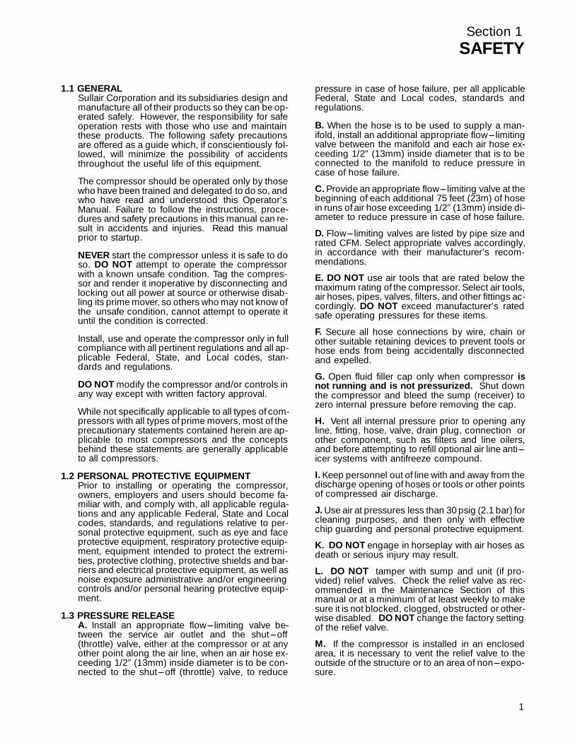
TABLE OF CONTENTS
Section 1 PAGE
SAFETY 1 1.1 GENERAL
1 1.2 PERSONAL PROTECTIVE EQUIPMENT
1 1.3 PRESSURE RELEASE
2 1.4 FIRE AND EXPLOSION
2 1.5 MOVING PARTS
2 1.6 HOT SURFACES, SHARP EDGES AND SHARP CORNERS
2 1.7 TOXIC AND IRRITATING SUBSTANCES
3 1.8 ELECTRICAL SHOCK
3 1.9 LIFTING
4 1.10 ENTRAPMENT
Section 2DESCRIPTION 5 2.1 INTRODUCTION
5 2.2 DESCRIPTION OF COMPONENTS
5 2.3 SULLAIR COMPRESSOR UNIT,FUNCTIONAL DESCRIPTION
6 2.4 COMPRESSOR COOLING AND LUBRICATIONSYSTEM, FUNCTIONAL DESCRIPTION
8 2.5 COMPRESSOR DISCHARGE SYSTEM,FUNCTIONAL DESCRIPTION
9 2.6 CONTROL SYSTEM, FUNCTIONAL DESCRIPTION
11 2.7 AIR INLET SYSTEM, FUNCTIONAL DESCRIPTION
11 2.8 INSTRUMENT PANEL GROUP, FUNCTIONAL DESCRIPTION
Section 3SPECIFICATIONS 13 3.1 TABLE OF SPECIFICATIONS
14 3.2 LUBRICATION GUIDE---STANDARD COMPRESSORS(All 12 Series; 16 Series---60 and 75HP)
14 3.3 LUBRICATION GUIDE---STANDARD COMPRESSORS(16 Series---100HP)
14 3.4 LUBRICATION GUIDE---24KT COMPRESSORS
Section 4INSTALLATION 15 4.1 MOUNTING OF COMPRESSOR
15 4.2 VENTILATION AND COOLING
15 4.3 SERVICE AIR PIPING
15 4.4 COUPLING ALIGNMENT CHECK
15 4.5 FLUID LEVEL CHECK
15 4.6 ELECTRICAL PREPARATION
17 4.7 MOTOR ROTATION DIRECTION CHECK

TABLE OF CONTENTS(CONTINUED)
Section 5 PAGE
OPERATION 19 5.1 GENERAL
19 5.2 PURPOSE OF CONTROLS
20 5.3 INITIAL START---UP PROCEDURE
21 5.4 SUBSEQUENT START---UP PROCEDURE
21 5.5 SHUTDOWN PROCEDURE
Section 6MAINTENANCE 23 6.1 GENERAL
23 6.2 DAILY OPERATION
23 6.3 MAINTENANCE AFTER INITIAL 50 HOURS OF OPERATION
23 6.4 MAINTENANCE EVERY 4000 HOURS
23 6.5 FILTER MAINTENANCE
23 6.6 SEPARATOR MAINTENANCE
23 6.7 PARTS REPLACEMENT AND ADJUSTMENT PROCEDURES
27 6.8 TROUBLESHOOTING
Section 7ILLUSTRATIONS ANDPARTS LIST 31 7.1 PROCEDURE FOR ORDERING PARTS
31 7.2 RECOMMENDED SPARE PARTS LIST
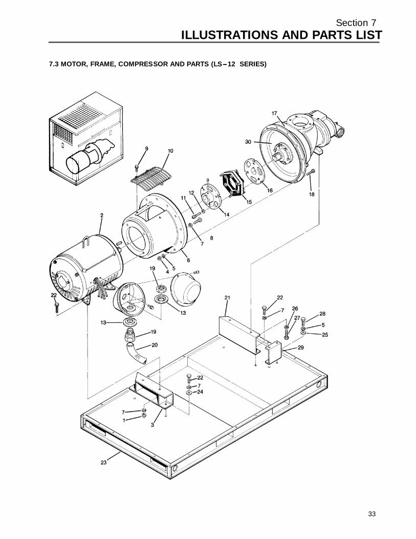
34 7.3 MOTOR, FRAME, COMPRESSOR AND PARTS(LS---12 SERIES)
38 7.4 MOTOR, FRAME, COMPRESSOR AND PARTS(LS---16 SERIES 60---75HP)
40 7.5 MOTOR, FRAME, COMPRESSOR AND PARTS(LS---16 SERIES 100HP)
42 7.6 AIR INLET SYSTEM (LS---12 AND LS---16 SERIES)
44 7.7 COMPRESSOR COOLING AND LUBRICATION SYSTEM(AIR---COOLED, LS---12 SERIES 40 AND 50HP)
48 7.8 COMPRESSOR COOLING AND LUBRICATION SYSTEM(WATER---COOLED, LS---12 SERIES 40 AND 50HP)
52 7.9 COMPRESSOR COOLING AND LUBRICATION SYSTEM(AIR---COOLED, LS---12 SERIES 60HP,AND LS---16 SERIES 60---75HP)
56 7.10 COMPRESSOR COOLING AND LUBRICATION SYSTEM(AIR---COOLED, LS---16 SERIES 100HP)
60 7.11 COMPRESSOR COOLING AND LUBRICATION SYSTEM(WATER---COOLED, LS---12 SERIES 60HP,AND LS---16 SERIES 60---75HP)
66 7.12 COMPRESSOR COOLING AND LUBRICATION SYSTEM(WATER---COOLED, LS---16 SERIES 100HP)
72 7.13 COMPRESSOR DISCHARGE SYSTEM(LS---12 AND LS---16 SERIES)
76 7.14 AIR---COOLED COOLING ASSEMBLY (LS---12 AND LS---16 SERIES)
80 7.15 CAPACITY CONTROL SYSTEM (LS---12 AND LS---16 SERIES)

TABLE OF CONTENTS(CONTINUED)
Section 7 PAGE
ILLUSTRATIONS ANDPARTS LIST(CONTINUED) 84 7.16 INSTRUMENT PANEL AND PARTS (LS---12 AND LS---16 SERIES)
86 7.17 ELECTRO---PNEUMATIC CONTROL SYSTEM(LS---12 AND LS---16 SERIES)
88 7.18 ELECTRIC CONTROL BOX (LS---12 AND LS---16 SERIES)
92 7.19 CANOPY ENCLOSURE AND PARTS (LS---12 AND LS---16 SERIES)
96 7.20 DECAL GROUP
104 7.21 WIRING DIAGRAM---SINGLE CONTROL
105 7.22 WIRING DIAGRAM---SINGLE CONTROLWITH ANNUNCIATOR
106 7.23 WIRING DIAGRAM---DUAL CONTROL
107 7.24 WIRING DIAGRAM---DUAL CONTROLWITH ANNUNCIATOR
Section 1SAFETY
1.1 GENERALSullair Corporation and its subsidiaries design andmanufacture all of their products so they can be op-erated safely. However, the responsibility for safeoperation rests with those who use and maintainthese products. The following safety precautionsare offered as a guide which, if conscientiously fol-lowed, will minimize the possibility of accidentsthroughout the useful life of this equipment.
The compressor should be operated only by thosewho have been trained and delegated to do so, andwho have read and understood this Operator’sManual. Failure to follow the instructions, proce-dures and safety precautions in this manual can re-sult in accidents and injuries. Read this manualprior to startup.
NEVER start the compressor unless it is safe to doso. DO NOT attempt to operate the compressorwith a known unsafe condition. Tag the compres-sor and render it inoperative by disconnecting andlocking out all power at source or otherwise disab-ling its prime mover, so others who may not know ofthe unsafe condition, cannot attempt to operate ituntil the condition is corrected.
Install, use and operate the compressor only in fullcompliance with all pertinent regulations and all ap-plicable Federal, State, and Local codes, stan-dards and regulations.
DO NOT modify the compressor and/or controls inany way except with written factory approval.
While not specifically applicable to all types of com-pressors with all types of prime movers, most of theprecautionary statements contained herein are ap-plicable to most compressors and the conceptsbehind these statements are generally applicableto all compressors.
1.2 PERSONAL PROTECTIVE EQUIPMENTPrior to installing or operating the compressor,owners, employers and users should become fa-miliar with, and comply with, all applicable regula-tions and any applicable Federal, State and Localcodes, standards, and regulations relative to per-sonal protective equipment, such as eye and faceprotective equipment, respiratory protective equip-ment, equipment intended to protect the extremi-ties, protective clothing, protective shields and bar-riers and electrical protective equipment, as well asnoise exposure administrative and/or engineeringcontrols and/or personal hearing protective equip-ment.
1.3 PRESSURE RELEASEA. Install an appropriate flow--- limiting valve be-tween the service air outlet and the shut---off(throttle) valve, either at the compressor or at anyother point along the air line, when an air hose ex-ceeding 1/2” (13mm) inside diameter is to be con-nected to the shut---off (throttle) valve, to reduce
pressure in case of hose failure, per all applicableFederal, State and Local codes, standards andregulations.
B. When the hose is to be used to supply a man-ifold, install an additional appropriate flow--- limitingvalve between the manifold and each air hose ex-ceeding 1/2” (13mm) inside diameter that is to beconnected to the manifold to reduce pressure incase of hose failure.
C. Provide an appropriate flow--- limiting valve at thebeginning of each additional 75 feet (23m) of hosein runs of air hose exceeding 1/2” (13mm) inside di-ameter to reduce pressure in case of hose failure.
D. Flow--- limiting valves are listed by pipe size andrated CFM. Select appropriate valves accordingly,in accordance with their manufacturer’s recom-mendations.
E. DO NOT use air tools that are rated below themaximum rating of the compressor. Select air tools,air hoses, pipes, valves, filters, and other fittings ac-cordingly. DO NOT exceed manufacturer’s ratedsafe operating pressures for these items.
F. Secure all hose connections by wire, chain orother suitable retaining devices to prevent tools orhose ends from being accidentally disconnectedand expelled.
G. Open fluid filler cap only when compressor isnot running and is not pressurized. Shut downthe compressor and bleed the sump (receiver) tozero internal pressure before removing the cap.
H. Vent all internal pressure prior to opening anyline, fitting, hose, valve, drain plug, connection orother component, such as filters and line oilers,and before attempting to refill optional air line anti---icer systems with antifreeze compound.
I. Keep personnel out of line with and away from thedischarge opening of hoses or tools or other pointsof compressed air discharge.
J. Use air at pressures less than 30 psig (2.1 bar) forcleaning purposes, and then only with effectivechip guarding and personal protective equipment.
K. DO NOT engage in horseplay with air hoses asdeath or serious injury may result.
L. DO NOT tamper with sump and unit (if pro-vided) relief valves. Check the relief valve as rec-ommended in the Maintenance Section of thismanual or at a minimum of at least weekly to makesure it is not blocked, clogged, obstructed or other-wise disabled. DO NOT change the factory settingof the relief valve.
M. If the compressor is installed in an enclosedarea, it is necessary to vent the relief valve to theoutside of the structure or to an area of non---expo-sure.
1
Section 1SAFETY
2
1.4 FIRE AND EXPLOSION
WARNING!
When installing a Base Load Transfer (BLT) Sys-tem, remove jumpers between 16---17 & 18---19(Dual Control Compressors) so the other com-pressor does not backfeed defeating the shut-down circuitry.
A. Clean up spills of lubricant or other combustiblesubstances immediately, if such spills occur.
B. Shut off the compressor and allow it to cool.Then keep sparks, flames and other sources ofignition away and DO NOT permit smoking in thevicinity when checking or adding lubricant or whenrefilling air line anti--- icer systems with antifreezecompound.
C. DO NOT permit fluids, including air line anti---icer system antifreeze compound or fluid film to ac-cumulate on, under, or around acoustical material,or on any external surfaces of the air compressor oron internal surfaces of the enclosure. Wipe downusing an aqueous industrial cleaner or steam---clean as required. If necessary, remove acousticalmaterial, clean all surfaces and then replaceacoustical material. Any acoustical material with aprotective covering that has been torn or punc-tured should be replaced immediately to preventaccumulation of liquids or fluid film within the mate-rial. DO NOT use flammable solvents for cleaningpurposes.
D. Disconnect and lock out all power at source priorto attempting any repairs or cleaning of the com-pressor or of the inside of the enclosure, if any.
E. Keep electrical wiring, including all terminals andpressure connectors in good condition. Replaceany wiring that has cracked, cut abraded or other-wise degraded insulation, or terminals that areworn, discolored or corroded. Keep all terminalsand pressure connectors clean and tight.
F. Keep grounded and/or conductive objects suchas tools away from exposed live electrical partssuch as terminals to avoid arcing which mightserve as a source of ignition.
G. Remove any acoustical material or other materi-al that may be damaged by heat or that may sup-port combustion and is in close proximity, prior toattempting weld repairs.
H. Keep suitable fully charged fire extinguisher orextinguishers nearby when servicing and operat-ing the compressor.
I. Keep oily rags, trash, leaves, litter or other com-bustibles out of and away from the compressor.
J. DO NOT operate the compressor without properflow of cooling air or water or with inadequate flowof lubricant or with degraded lubricant.
K. DO NOT attempt to operate the compressor inany classification of hazardous environment unlessthe compressor has been specially designed andmanufactured for that duty.
1.5 MOVING PARTSA. Keep hands, arms and other parts of the bodyand also clothing away from couplings, fans andother moving parts.
B. DO NOT attempt to operate the compressorwith the fan, coupling or other guards removed.
C. Wear snug--- fitting clothing and confine long hairwhen working around this compressor, especiallywhen exposed to hot or moving parts.
D. Keep access doors, if any, closed except whenmaking repairs or adjustments.
E. Make sure all personnel are out of and/or clear ofthe compressor prior to attempting to start or oper-ate it.
F. Disconnect and lock out all power at source andverify at the compressor that all circuits are de---en-ergized to minimize the possibility of accidentalstart---up or operation, prior to attempting repairsor adjustments. This is especially important whencompressors are remotely controlled.
G. Keep hands, feet, floors, controls and walkingsurfaces clean and free of fluid, water, or other liq-uids to minimize the possibility of slips and falls.
1.6 HOT SURFACES, SHARP EDGES AND SHARPCORNERSA. Avoid bodily contact with hot fluid, hot coolant,hot surfaces and sharp edges and corners.
B. Keep all parts of the body away from all points ofair discharge.
C. Wear personal protective equipment includinggloves and head covering when working in, on oraround the compressor.
D. Keep a first aid kit handy. Seek medical assis-tance promptly in case of injury. DO NOT ignoresmall cuts and burns as they may lead to infection.
1.7 TOXIC AND IRRITATING SUBSTANCESA. DO NOT use air from this compressor for respi-ration (breathing) except in full compliance withany Federal, State or Local Codes or regulations.
DANGER!
Death or serious injury can result from inhalingcompressed air without using proper safetyequipment.
B. DO NOT use air line anti--- icer systems in airlines supplying respirators or other breathing airutilization equipment and DO NOT discharge airfrom these systems in unventilated or other con-fined areas.

Section 1SAFETY
C. Operate the compressor only in open or ade-quately ventilated areas.
D. Locate the compressor or provide a remote inletso that it is not likely to ingest exhaust fumes or oth-er toxic, noxious or corrosive fumes or substances.
E. Coolants and lubricants used in this compressorare typical of the industry. Care should be taken toavoid accidental ingestion and/or skin contact. Inthe event of ingestion, seek medical treatmentpromptly. Wash with soap and water in the event ofskin contact. Consult the compressor operator’smanual lubrication section for information pertain-ing to compressor fluid fill.
F. Wear goggles or a full face shield when addingantifreeze compound to air line anti--- icer systems.
G. If air line anti--- icer system antifreeze compoundenters the eyes or if fumes irritate the eyes, theyshould be washed with large quantities of cleanwater for 15 minutes. A physician, preferably aneye specialist, should be contacted immediately.
H. DO NOT store air line anti--- icer system anti-freeze compound in confined areas.
I. The antifreeze compound used in air line anti-freeze systems contains methanol and is toxic,harmful, or fatal if swallowed. Avoid contact with theskin or eyes and avoid breathing the fumes. If swal-lowed, induce vomiting by administering a table-spoon of salt, in each glass of clean, warm wateruntil vomit is clear, then administer two teaspoonsof baking soda in a glass of clean water. Have pa-tient lay down and cover eyes to exclude light. Calla physician immediately.
1.8 ELECTRICAL SHOCKA. This compressor should be installed and main-tained in full compliance with all applicable Federal,State and Local codes, standards and regulations,including those of the National Electrical Code, andalso including those relative to equipment ground-ing conductors, and only by personnel that aretrained, qualified and delegated to do so.
B. Keep all parts of the body and any hand---heldtools or other conductive objects away from ex-posed live parts of electrical system. Maintain dryfooting, stand on insulating surfaces and DO NOTcontact any other portion of the compressor whenmaking adjustments or repairs to exposed liveparts of the electrical system. Make all such adjust-ments or repairs with one hand only, so as to mini-mize the possibility of creating a current paththrough the heart.
C. Attempt repairs in clean, dry and well lighted andventilated areas only.
D. DO NOT leave the compressor unattended withopen electrical enclosures. If necessary to do so,then disconnect, lock out and tag all power atsource so others will not inadvertently restore pow-er.
E. Disconnect, lock out, and tag all power at sourceprior to attempting repairs or adjustments to rotat-ing machinery and prior to handling any un-grounded conductors.F. Dry test all shutdown circuits prior to starting thecompressor after installation.
1.9 LIFTINGA. If the compressor is provided with a lifting bail,then lift by the bail provided. If no bail is provided,then lift by sling. Compressors to be air lifted by he-licopter must not be supported by the lifting bail butby slings instead. In any event, lift and/or handleonly in full compliance with Federal, State and Lo-cal codes.
B. Inspect points of attachment for cracked weldsand for cracked, bent, corroded or otherwise de-graded members and for loose bolts or nuts prior tolifting.C. Make sure entire lifting, rigging and supportingstructure has been inspected, is in good conditionand has a rated capacity of at least the weight ofthe compressor. If you are unsure of the weight,then weigh compressor before lifting.D. Make sure lifting hook has a functional safetylatch or equivalent, and is fully engaged andlatched on the bail or slings.E. Use guide ropes or equivalent to prevent twistingor swinging of the compressor once it has beenlifted clear of the ground.F. DO NOT attempt to lift in high winds.G. Keep all personnel out from under and awayfrom the compressor whenever it is suspended.H. Lift compressor no higher than necessary.I. Keep lift operator in constant attendance when-ever compressor is suspended.J. Set compressor down only on a level surface ca-pable of safely supporting at least its weight and itsloading unit.K. When moving compressors by forklift truck, uti-lize fork pockets if provided. Otherwise, utilize pal-let if provided. If neither fork pockets or pallet areprovided, then make sure compressor is secureand well balanced on forks before attempting toraise or transport it any significant distance.L. Make sure forklift truck forks are fully engagedand tipped back prior to lifting or transporting thecompressor.M. Forklift no higher than necessary to clear ob-stacles at floor level and transport and corner atminimum practical speeds.N. Make sure pallet---mounted compressors arefirmly bolted or otherwise secured to the pallet priorto attempting to forklift or transport them. NEVERattempt to forklift a compressor that is not securedto its pallet, as uneven floors or sudden stops may
3
Section 1SAFETY
4
cause the compressor to tumble off, possibly caus-ing serious injury or property damage in the pro-cess.O. DO NOT use the lifting eye bolt on the compres-sor motor, if supplied, to lift the entire compressorpackage.
1.10 ENTRAPMENTA. If the compressor enclosure is large enough tohold a person and if it is necessary to enter it to per-
form service adjustments, inform other personnelbefore doing so, or else secure and tag the accessdoor in the open position to avoid the possibility ofothers closing and possibly latching the door withpersonnel inside.
B. Make sure all personnel are out of compressorbefore closing and latching enclosure doors.
Section 2DESCRIPTION
2.1 INTRODUCTIONYour new Sullair flood--- lubricated rotary screw aircompressor will provide you with a unique experi-ence in improved reliability and greatly reducedmaintenance.
Compared to other types of compressors, the Sull-air rotary screw is unique in mechanical reliability,with “no wear” and “no inspection” required of theworking parts within the compressor unit.
Read Section 6 (Maintenance) to see how surpris-ingly easy it is to keep your air compressor in topoperating condition.
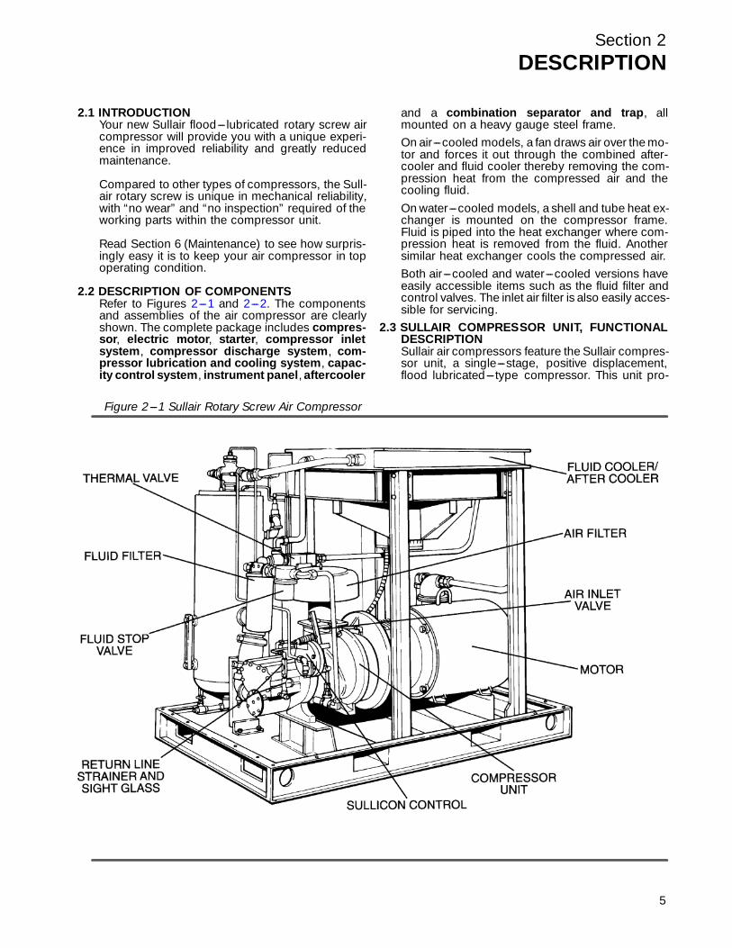
2.2 DESCRIPTION OF COMPONENTSRefer to Figur es 2 --- 1 a nd 2 --- 2 . The c omponentsand assemblies of the air compressor are clearlyshown. The complete package includes compres-sor, electric motor, starter, compressor inletsystem, compressor discharge system, com-pressor lubrication and cooling system, capac-ity control system, instrument panel, aftercooler
and a combination separator and trap, allmounted on a heavy gauge steel frame.On air---cooled models, a fan draws air over the mo-tor and forces it out through the combined after-cooler and fluid cooler thereby removing the com-pression heat from the compressed air and thecooling fluid.On water---cooled models, a shell and tube heat ex-changer is mounted on the compressor frame.Fluid is piped into the heat exchanger where com-pression heat is removed from the fluid. Anothersimilar heat exchanger cools the compressed air.Both air---cooled and water---cooled versions haveeasily accessible items such as the fluid filter andcontrol valves. The inlet air filter is also easily acces-sible for servicing.
2.3 SULLAIR COMPRESSOR UNIT, FUNCTIONALDESCRIPTIONSullair air compressors feature the Sullair compres-sor unit, a single---stage, positive displacement,flood lubricated--- type compressor. This unit pro-
Figure 2---1 Sullair Rotary Screw Air Compressor
5

Section 2DESCRIPTION
6
vides continuous pulse--- free compression to meetyour needs. With a Sullair compressor, there is nomaintenance or inspection of the internal parts ofthe compressor unit permitted in accordance withthe terms of the warranty.
Sullair 24KT compressors are filled with a fluidwhich rarely needs to be changed. In the event achange of fluid is required, use only Sullair 24KTfluid. MIXING OF OTHER LUBRICANTS WITHINTHE COMPRESSOR UNIT WILL VOID ALL WAR-RANTIES!
Sullair recommends that a 24KT sample be takenat the first filter change and sent to the factory foranalysis. This is a free service. The sample kit withinstruction and self---addressed container is to besupplied by your Sullair dealer at start---up. Theuser will receive an analysis report with recommen-dations.
Fluid is injected into the compressor unit in largequantities and mixes directly with the air as the ro-
tors turn, compressing the air. The fluid flow hasthree basic functions:1. As coolant, it controls the rise of air temperature
normally associated with the heat of compres-sion.
2. Seals the leakage paths between the rotors andthe stator and also between the rotors them-selves.
3. Acts as a lubricating film between the rotors al-lowing one rotor to directly drive the other, whichis an idler.
After the air/fluid mixture is discharged from thecompressor unit, the fluid is separated from the air.At this time, the air flows through an aftercooler andseparator, then to your service line while the fluid isbeing cooled in preparation for reinjection.
Figure 2---2 Sullair Rotary Screw Air Compressor (Typical Air ---cooled Compressor Shown)
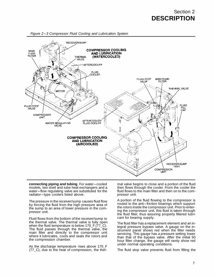
2.4 COMPRESSOR COOLING AND LUBRICATIONSYSTEM, FUNCTIONAL DESCRIPTIONR e f e r t o F i g u r e 2 --- 3 . T h e cooling system ( a i r ---cooled version) consists of a fan, fan motor, radia-tor---type aftercooler/fluid cooler, full flow fluidfilter, thermal valve, fluid stop valve and inter-
Section 2DESCRIPTION
connecting piping and tubing. For water---cooledmodels, two shell and tube heat exchangers and awater--- flow regulating valve are substituted for theradiator--- type coolers listed above.
The pressure in the receiver/sump causes fluid flowby forcing the fluid from the high pressure area ofthe sump to an area of lower pressure in the com-pressor unit.
Fluid flows from the bottom of the receiver/sump tothe thermal valve. The thermal valve is fully openwhen the fluid temperature is below 170_F (77_C).The fluid passes through the thermal valve, themain filter and directly to the compressor unitwhere it lubricates, cools and seals the rotors andthe compression chamber.
As the discharge temperature rises above 170_F(77_C), due to the heat of compression, the ther-
mal valve begins to close and a portion of the fluidthen flows through the cooler. From the cooler thefluid flows to the main filter and then on to the com-pressor unit.
A portion of the fluid flowing to the compressor isrouted to the anti--- friction bearings which supportthe rotors inside the compressor unit. Prior to enter-ing the compressor unit, this fluid is taken throughthe fluid filter, thus assuring properly filtered lubri-cant for bearing supply.
The fluid filter has a replacement element and an in-tegral pressure bypass valve. A gauge on the in-strument panel shows red when the filter needsservicing. This gauge has a pressure setting lowerthan that of the bypass valve. After the initial 50hour filter change, the gauge will rarely show redunder normal operating conditions.
The fluid stop valve prevents fluid from filling the
Figure 2---3 Compressor Fluid Cooling and Lubrication System
7
Section 2DESCRIPTION
8
compressor unit when the compressor is shutdown. When the compressor is operating, the fluidstop valve is held open by air pressure from thecompressor unit allowing a free flow of fluid fromthe receiver/sump back to the compressor unit. Onshutdown, the compressor unit pressure is re-duced, causing the fluid stop valve to close and iso-late the compressor unit from the cooling system.
Water---cooled versions of the compressor have awater--- flow regulating valve (not shown) which op-erates to conserve water during periods of varyingload on the compressor. This same valve automati-cally shuts off the water supply when the compres-sor is shut down. In addition, water---cooled mod-els have a water pressure switch to prevent opera-
tion with inadequate water pressure.
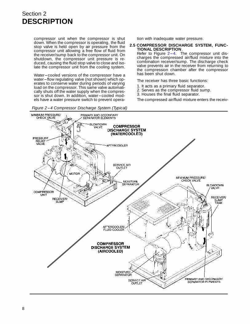
Figure 2---4 Compressor Discharge System (Typical)
2.5 COMPRESSOR DISCHARGE SYSTEM, FUNC-TIONAL DESCRIPTION .Refer to Figur e 2 --- 4 . The c ompr essor unit dis -charges the compressed air/fluid mixture into thecombination receiver/sump. The discharge checkvalve prevents air in the receiver from returning tothe compression chamber after the compressorhas been shut down.
The receiver has three basic functions:1. It acts as a primary fluid separator.2. Serves as the compressor fluid sump.3. Houses the final fluid separator.The compressed air/fluid mixture enters the receiv-
Section 2DESCRIPTION
er and is directed towards the bottom of the sepa-rator element. The direction of movement ischanged and its velocity significantly reduced, thuscausing large droplets of fluid to separate and fall tothe bottom of the receiver/sump. The fractional per-centage of fluid remaining in the compressed aircollects on the surface of the separator element asthe compressed air flows through the separator.Return lines (or scavenge tubes) lead from the bot-tom of the separators’ elements to the inlet regionof the compressor unit. Fluid collecting on the bot-tom of the separator is returned to the compressorby a pressure differential between the receiver andthe compressor inlet. Visual sight glasses are lo-cated on the return lines to observe the fluid flow.There are also orifices in the return line (protectedby strainers) to assure proper flow. A gauge, lo-cated on the instrument panel, shows red if abnor-mal pressure drop through the separators devel-ops. At this time, separator element replacement isnecessary.
The receiver is ASME code rated at 175 psig (12.1bar) working pressure. A minimum pressure/checkvalve, located downstream from the separator, as-sures a minimum receiver pressure of 55 psig (3.8bar) during all conditions. This pressure is neces-sary for proper air/fluid separation and proper fluidcirculation.
A terminal check valve is incorporated into the mini-mum pressure/check valve to prevent compressedair in the service line form bleeding back into the re-ceiver on shutdown and during operation of thecompressor in an unloaded condition.
A pressure relief valve (located on the wet side ofthe separator) is set to open if the sump pressureexceeds 175 psig (12.1 bar). A temperature switchwill shut down the compressor if the discharge tem-perature reaches 235_F (113_C).
All compressor models are equipped with a highpressure shutdown switch to shut down the com-pressor at 135 psig (9.3 bar). This prevents thepressure relief valve from opening under routineconditions, thereby preventing fluid loss throughthe pressure relief valve.
WARNING!
DO NOT remove caps, plugs, and/or other com-ponents when compressor is running or pressur-ized.
Stop compressor and relieve all internal pres-sure before doing so.
Fluid is added to the sump via a capped fluid filleropening, placed low on the tank to prevent overfil-ling of the sump. A sight glass enables the operatorto visually monitor the sump fluid level.
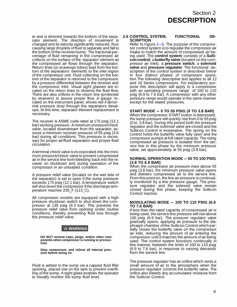
2.6 CONTROL SYSTEM, FUNCTIONAL DE-SCRIPTIONRefer to Figure 2---5. The purpose of the compres-sor control system is to regulate the compressor airintake to match the amount of compressed air be-ing used. The control system consists of a Sulli-con control, a butterfly valve (located on the com-pressor air inlet), a pressure switch, a solenoidvalve and pressure regulator. The functional de-scription of the control system is described belowin four distinct phases of compressor opera-tion.The following descriptive text applies to all 12and 16 Series compressors. For explanatory pur-pose this description will apply to a compressorwith an operating pressure range of 100 to 110psig (6.9 to 7.6 bar). A compressor with any otherpressure range would operate in the same mannerexcept for the stated pressures.
START MODE --- 0 TO 55 PSIG (0 TO 3.8 BAR)When the compressor START button is depressed,the sump pressure will quickly rise from 0 to 55 psig(0 to 3.8 bar). During this period both the pressureregulator and the solenoid valve are closed and theSullicon Control is inoperative. The spring on thecontrol holds the butterfly valve fully open and thecompressor pumps at full rated capacity. The risingcompressed air pressure is isolated from the ser-vice line in this phase by the minimum pressurevalve, set approximately at 55 psig (3.8 bar).
NORMAL OPERATION MODE --- 55 TO 100 PSIG(3.8 TO 6.9 BAR)When the compressor air pressure rises above 55psig (3.8 bar), the minimum pressure valve opensand delivers compressed air to the service line.From this point on, the line air pressure is continual-ly monitored by a line pressure gauge. The pres-sure regulator and the solenoid valve remainclosed during this phase, keeping the SulliconControl inactive.
MODULATING MODE --- 100 TO 110 PSIG (6.9TO 7.6 BAR)If less than the rated capacity of compressed air isbeing used, the service line pressure will rise above100 psig (6.9 bar). The pressure regulator valvegradually opens, applying air pressure to the dia-phragm chamber of the Sullicon Control which par-tially closes the butterfly valve on the compressorair inlet, reducing the amount of air entering thecompressor until it matches the amount of air beingused. The control system functions continually inthis manner, between the limits of 100 to 110 psig(6.9 to 7.6 bar), in response to varying demandsfrom the service line.
The pressure regulator has an orifice which vents asmall amount of air to the atmosphere when thepressure regulator controls the butterfly valve. Theorifice also bleeds any accumulated moisture fromthe Sullicon Control.
9
Section 2DESCRIPTION
10
Figure 2---5A Control System, Sequence of Operation (Typical)
SOLENOID
SOLENOID

Section 2DESCRIPTION
UNLOAD --- IN EXCESS OF 110 PSIG (7.6 BAR)LINE PRESSUREWhen no air is being used, the service line pres-sures rises to the setting (cut---out pressure) of thepressure switch. The pressure switch opens, inter-rupting the electrical power to the solenoid valve. Atthis time, the solenoid valve allows dry sump tankair pressure to be applied directly to the control dia-phragm, keeping the butterfly valve closed. Simul-taneously, the solenoid valve sends a pneumaticsignal to the blowdown valve. The blowdown valveopens the sump to the atmosphere, reducing thesump pressure to approximately 40 to 50 psig (2.8to 3.8 bar). The check valve in the air service lineprevents line pressure from returning to the sump.
When the line pressure drops to the low setting(cut--- in pressure) of the pressure switch (usually100 psig [6.9 bar] on low pressure compressorsand 115 psig [7.9 bar] on high pressure compres-sors), the pressure switch closes, re---energizingthe three---way solenoid valve and allowing theblowdown valve to close. The re---energized sole-noid valve again prevents line pressure from reach-ing the Sullicon Control. Should the pressure beginto rise, the pressure regulator will resume its nor-mal function as previously described.
For a compressor with varied periods of time whenthere are no air requirements, a “dual control” op-
tion is available. This option allows you to set thecompressor in an automatic position whereby thecompressor will shut down when no compressedair requirement is present and restart as com-pressed air is needed.
Figure 2---5B Control System, Sequence of Operation (Typical)
SOLENOID
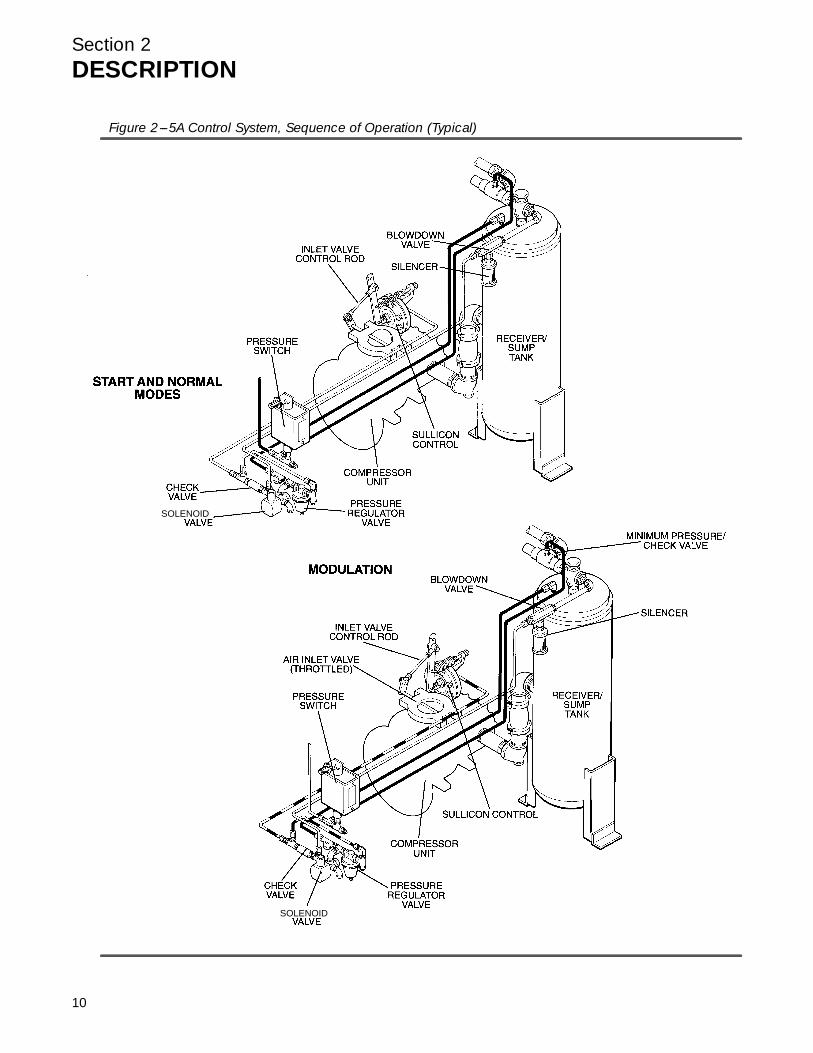
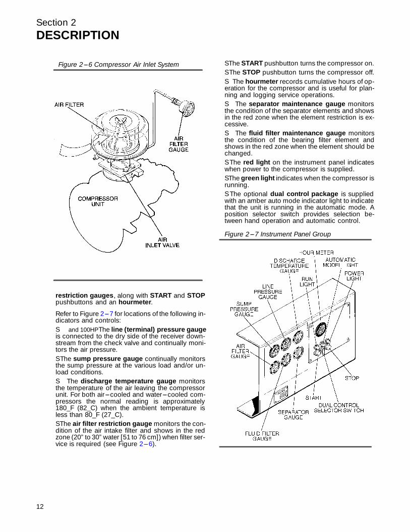
2.7 AIR INLET SYSTEM, FUNCTIONAL DE-SCRIPTIONR e f e r t o F i g u r e 2 --- 6 . T h e c om p r essor i n l et sy s -tem consists of a dry---type air filter, a restrictiongauge and a control valve.
The restriction gauge, located on the compressorinstrument panel, indicates the condition of the airfilter by showing red when filter maintenance is re-quired.
The butterfly--- type air inlet valve directly controlsthe amount of air intake to the compressor in re-sponse to the operation of the Sullicon Control (seeS ec tion 2 . 6 , Contr ol S y stem).
See Section 6 for Air Filter Maintenance Proce-dures.
2.8 INSTRUMENT PANEL GROUP, FUNCTIONALDESCRIPTIONRef er to Figur e 2 --- 7 f or spec if ic l oc a tion of par ts de -scribed. The instrument panel group consists of apanel containing the line pressure, sump pres-sure and discharge temperature gauges, the airfilter, the separator element and the fluid filter,
11
Section 2DESCRIPTION
12
restriction gauges, along with START and STOPpushbuttons and an hourmeter.
Refer to Figur e 2 --- 7 f or l oc a tions of the fol l owing in -dicators and controls:S and 100HPThe line (terminal) pressure gaugeis connected to the dry side of the receiver down-stream from the check valve and continually moni-tors the air pressure.S The sump pressure gauge continually monitorsthe sump pressure at the various load and/or un-load conditions.S The discharge temperature gauge monitorsthe temperature of the air leaving the compressorunit. For both air---cooled and water---cooled com-pressors the normal reading is approximately180_F (82_C) when the ambient temperature isless than 80_F (27_C).S The air filter restriction gauge monitors the con-dition of the air intake filter and shows in the redzone (20” to 30” water [51 to 76 cm]) when filter ser-v ic e is r equir ed ( s ee Figur e 2 --- 6 ) .
S The START pushbutton turns the compressor on.S The STOP pushbutton turns the compressor off.S The hourmeter records cumulative hours of op-eration for the compressor and is useful for plan-ning and logging service operations.S The separator maintenance gauge monitorsthe condition of the separator elements and showsin the red zone when the element restriction is ex-cessive.S The fluid filter maintenance gauge monitorsthe condition of the bearing filter element andshows in the red zone when the element should bechanged.S The red light on the instrument panel indicateswhen power to the compressor is supplied.S The green light indicates when the compressor isrunning.S The optional dual control package is suppliedwith an amber auto mode indicator light to indicatethat the unit is running in the automatic mode. Aposition selector switch provides selection be-tween hand operation and automatic control.
Figure 2---6 Compressor Air Inlet System
Figure 2---7 Instrument Panel Group
Section 3SPECIFICATIONS
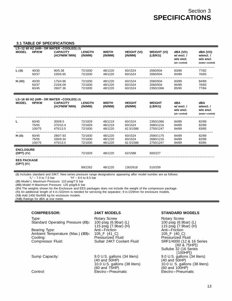
3.1 TABLE OF SPECIFICATIONSLS--12 60 HZ (AIR-- OR WATER --COOLED) (I)MODEL HP/KW CAPACITY LENGTH WIDTH HEIGHT (VI) WEIGHT (VI) dBA (VII) dBA (VII)
(ACFM/M!/MIN) (IN/MM) (IN/MM) (IN/MM) (LB/KG) w/ encl. / w/encl. /w/o encl. w/o encl.(air--cooled) (water--cooled)
--------------------------------------------------------------------------------------------------------------------------------------------------------------------------------------------------------------------------------------------L (II) 40/30 90/5.38 72/1830 48/1220 60/1524 2060/934 83/89 77/82
50/37 235/6.65 72/1830 48/1220 60/1524 2060/934 84/89 76/83------------------------------------------------------------------------------------------------------------------------------------------------------------------------------------------------------------------------------------------H (III) 40/30 175/4.96 72/1830 48/1220 60/1524 2060/934 83/89 84/89
50/37 215/6.09 72/1830 48/1220 60/1524 2060/934 84/89 76/8360/45 260/7.36 72/1830 48/1220 60/1524 2350/1066 85/90 77/84
LS--16 60 HZ (AIR-- OR WATER --COOLED) (I)MODEL HP/KW CAPACITY LENGTH WIDTH HEIGHT WEIGHT dBA dBA
(ACFM/M!/MIN) (IN/MM) (IN/MM) (IN/MM) (LB/KG) w/ encl. / w/encl. /w/o encl. w/o encl.(air--cooled) (water--cooled)
--------------------------------------------------------------------------------------------------------------------------------------------------------------------------------------------------------------------------------------------L 60/45 300/8.5 72/1829 48/1219 60/1524 2350/1066 84/89 82/89
75/55 370/10.4 72/1829 48/1219 60/1524 2680/1216 84/89 82/89100/75 475/13.5 72/1830 48/1220 62.5/1588 2750/1247 84/89 83/85
------------------------------------------------------------------------------------------------------------------------------------------------------------------------------------------------------------------------------------------H (II) 60/45 280/7.93 72/1830 48/1220 60/1524 2590/1175 84/89 82/89
75/55 330/9.34 72/1830 48/1220 60/1524 2680/1216 84/89 82/89100/75 475/13.5 72/1830 48/1220 62.5/1588 2750/1247 84/89 83/85
ENCLOSURE(OPT) (IV) 72/1829 48/1220 62/1588 500/227--------------------------------------------------------------------------------------------------------------------------------------------------------------------------------------------------------------------------------------------EES PACKAGE(OPT) (IV)
89/2262 48/1220 130/2618 510/259
(I) Includes standard and 24KT. New series pressure range designations appearing after model number are as follows:“L” -- 7.0 to 7.5 bar “H” -- 8.0 to 8.5 bar
(II) Model L Maximum Pressure: 110 psig/7.6 bar(III) Model H Maximum Pressure: 125 psig/8.6 bar(IV) The weights shown for the Enclosure and EES packages does not include the weight of the compressor package.(V) An additional length of 4 in./102mm is needed for servicing the separator; 9 in./229mm for enclosure models.(VI) Add 1450 lbs/658 kg for enclosure models.(VII) Ratings for dBA at one meter.
COMPRESSOR: 24KT MODELS STANDARD MODELSType: Rotary Screw Rotary ScrewStandard Operating Pressure (II): 100 psig (6.9bar) (L) 100 psig (6.9bar) (L)
115 psig (7.9bar) (H) 115 psig (7.9bar) (H)Bearing Type: Anti---Friction Anti---FrictionAmbient Temperature (Max.) (III): 105_F (41_C) 105_F (40_C)Cooling: Pressurized Fluid Pressurized FluidCompressor Fluid: Sullair 24KT Coolant Fluid SRF1/4000 (12 & 16 Series
[60 & 75HP])Sullube 32 (16 Series
[100HP])Sump Capacity: 9.0 U.S. gallons (34 liters) 9.0 U.S. gallons (34 liters)
(40 and 50HP) (40 and 50HP)10.0 U.S. gallons (38 liters) 10.0 U. S. gallons (38 liters)(60 and 75HP) (60 and 100HP)
Control: Electro---Pneumatic Electro---Pneumatic
13
Section 3SPECIFICATIONS
14
3.1 TABLE OF SPECIFICATIONS (continued)
MOTOR: (60 Cycle Compressors)
24KT MODELS STANDARD MODELSSize: 40,50,60, 75HP 40,50,60, 75 & 100 HPType: C---Flanged, Open Dripproof, 460V, A.C., C---Flanged, Open Dripproof, 460V, A.C.,
Three Phase, 60 Cycles Three Phase, 60 Cycles40_C Maximum Ambient Temperature 40_C Maximum Ambient TemperatureOptions Available: 200V, 230V and 575V Options Available: 200V, 230V and 575VT.E.F.C. Also Available T.E.F.C. Also Available
Starter: 460V Full Voltage Magnetic 460V Full Voltage MagneticOptions Available: 200V, 230V and 575V Options Available 200V, 230V and 575V
Speed: 1770 RPM 1770RPM and 3550RPM (100HP)
3.2 LUBRICATION GUIDE---STANDARD COM-PRESSORS (All 12 Series; 16 Series --- 60 and75HP)Sullair standard compressors are filled with SRF1/4000 fluid factory fill.
WARNING!
Mixing of other lubricants within the compressorunit will void all warranties!
SRF 1/4000 fluid should be changed every 4000hours or once a year, whichever comes first. Thefluid should be changed more frequently under se-vere operating conditions, such as high ambienttemperatures coupled with high humidity, or whenhigh particle level, corrosive gases or strong oxidiz-ing gases are present in the air.
For extended life synthetic lubricants contact thenearest Sullair representative.
Maintenance of all other components is still recom-mended as indicated in the Operator’s Manual.
3.3 LUBRICATION GUIDE --- STANDARD COM-PRESSORS (16 Series --- 100HP)Sullair standard compressor are filled with Sullube32 fluid as factory fill.
WARNING!
Mixing of other lubricants within the compressorunit will void all warranties!
Sullube 32 fluid should be changed every 8000hours or once a year, whichever comes first. Thefluid should be changed more frequently under se-vere operating conditions, such as high ambienttemperatures coupled with high humidity, or whenhigh particulate level, corrosive gases or strong oxi-dizing gases are present in the air.
WARNING!
“The Plastic Pipe Institute recommends against theuse of thermoplastic pipe to transport compressedair or other compressed gases in exposed aboveground locations, e.g. in exposed plant piping.” (I)
Sullube 32 should not be used with PVC piping sys-tems. It may affect the bond at cemented joints. Cer-tain other plastic materials may also be affected.
(I) Plastic Pipe Institute, Recommendation B,Adopted January 19, 1972.
Maintenance of all other components is still recom-mended as indicated in the Operator’s Manual.
3.4 LUBRICATION GUIDE---24KT COMPRES-SORSSullair 24KT compressors are filled with a lubricantwhich rarely needs to be changed. In the event achange of fluid is required, use only Sullair 24KTfluid.
WARNING!
Mixing of other lubricants within the compressorunit will void all warranties!
Sullair recommends that a 24KT sample be takenat the first filter change and sent to the factory foranalysis. This is a free service. A sample kit with in-structions and self---addressed container is to besupplied by your Sullair Representative at start---up. The user will receive an analysis report with rec-ommendations.
APPLICATION GUIDESullair encourages the user to participate in a fluidanalysis program with the fluid suppliers. Thiscould result in a fluid change interval differing fromthat stated in the manual. Contact your Sullair deal-er for details.
Section 4INSTALLATION
4.1 MOUNTING OF COMPRESSORA foundation or mounting capable of supportingthe weight of the compressor, and rigid enough tomaintain the compressor frame level and the com-pressor in alignment, is required. The compressorframe must be leveled and secured with foundationbolts, and full uniform contact must be maintainedbetween the frame and foundation. No pipingloads shall be transmitted to the compressor at theexternal connections.
4.2 VENTILATION AND COOLINGFor air---cooled compressors, select a location topermit sufficient unobstructed air flowing in and outto the compressor to keep the operating tempera-ture stable. The minimum distance that the com-pressor should be from surrounding walls is three(3) feet (0.9 m). To prevent excessive ambient tem-perature rise, it is imperative to provide adequateventilation.
For water---cooled compressors, it is necessary tocheck the cooling water supply. The water systemmust be capable of supplying the following flows:
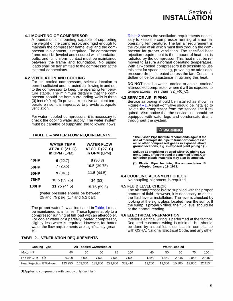
Ta bl e 2 shows the ventil ation r equir ements nec es -sary to keep the compressor running at a normaloperating temperature. The fan air requirement isthe volume of air which must flow through the com-pressor for proper ventilation. The specified heatrejection requirement is the amount of heat that isradiated by the compressor. This heat must be re-moved to assure a normal operating temperature.With air---cooled compressors it is possible to usethis heat for space heating, providing no additionalpressure drop is created across the fan. Consult aSullair office for assistance in utilizing this heat.
DO NOT install a water---cooled or an air---cooled/aftercooled compressor where it will be exposed totemperatures less than 32_F(0_C).
WATER TEMP. WATER FLOW
40HP
50HP
60HP
75HP
(water pressure should be between25 and 75 psig (1.7 and 5.2 bar).
100HP
AT 70_F (21_C)in GPM (LPM)
AT 80_F (27_C)in GPM (LPM)
6 (22.7) 8 (30.3)7 (26.5) 10.5 (39.75)
9 (34.1) 11.5 (44.5)
10.5 (39.75) 14 (53)11.75 (44.5) 15.75 (59.6)
TABLE 1 --- WATER FLOW REQUIREMENTS
The pr oper water flow as indic a ted in Table 1 mustbe maintained at all times. These figures apply to acompressor running at full load with an aftercooler.For cooler water or a partially loaded compressor,slightly less water is required. However, for hotterwater the flow requirements are significantly great-er.
TABEL 2--- VENTILATION REQUIREMENTS
Cooling Type Air---cooled w/Aftercooler Water---cooled
Motor HP 50
Fan Air CFM 6,000
Heat Rejection BTU/Hour 153,360
40 60 75
6,000 7,500 7,500
123,250 183,800 229,800
50
1,440
13,300
40 60 75
1,440 2,845 2,845
11,200 15,800 19,800
(I)
(I)Applies to compressors with canopy only (vent fan).
100
7,500
302,410
100
2,845
22,410
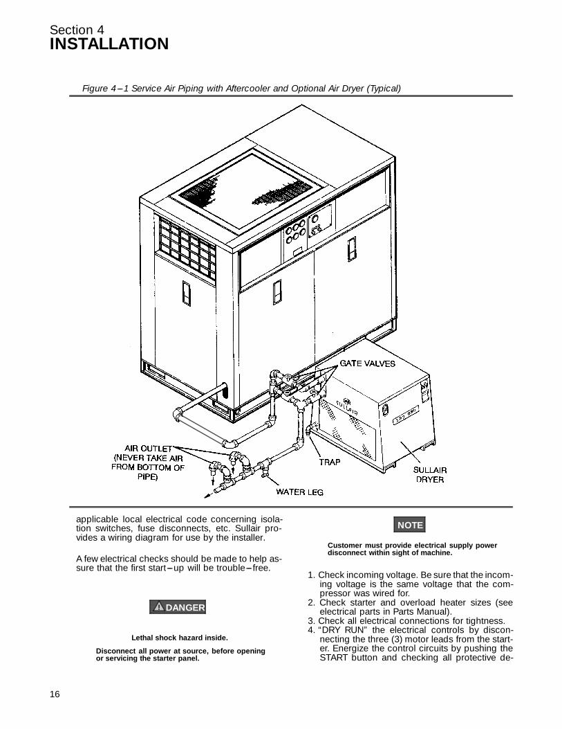
4.3 SERVICE AIR PIPINGService air piping should be installed as shown inF i g u r e 4 --- 1 . A s h u t --- o f f v a l v e s h o u l d b e i n s t a l l e d t oisolate the compressor from the service line if re-quired. Also notice that the service line should beequipped with water legs and condensate drainsthroughout the system.
WARNING!
“The Plastic Pipe Institute recommends against theuse of thermoplastic pipe to transport compressedair or other compressed gases in exposed aboveground locations, e.g. in exposed plant piping.” (I)
Sullube 32 should not be used with PVC piping sys-tems. It may affect the bond at cemented joints. Cer-tain other plastic materials may also be affected.
(I) Plastic Pipe Institute, Recommendation B,Adopted January 19, 1972.
4.4 COUPLING ALIGNMENT CHECKNo coupling alignment is required.
4.5 FLUID LEVEL CHECKThe air compressor is also supplied with the properamount of fluid. However, it is necessary to checkthe fluid level at installation. The level is checked bylooking at the sight glass located near the sump. Ifthe sump is properly filled, the fluid level should beat the normal reading.
4.6 ELECTRICAL PREPARATIONInterior electrical wiring is performed at the factory.Required customer wiring is minimal, but shouldbe done by a qualified electrician in compliancewith OSHA, National Electrical Code, and any other
15
Section 4INSTALLATION
16
applicable local electrical code concerning isola-tion switches, fuse disconnects, etc. Sullair pro-vides a wiring diagram for use by the installer.
A few electrical checks should be made to help as-sure that the first start---up will be trouble--- free.
DANGER!
Lethal shock hazard inside.
Disconnect all power at source, before openingor servicing the starter panel.
NOTE
Customer must provide electrical supply powerdisconnect within sight of machine.
1. Check incoming voltage. Be sure that the incom-ing voltage is the same voltage that the com-pressor was wired for.
2. Check starter and overload heater sizes (seeelectrical parts in Parts Manual).
3. Check all electrical connections for tightness.4. “DRY RUN” the electrical controls by discon-
necting the three (3) motor leads from the start-er. Energize the control circuits by pushing theSTART button and checking all protective de-
Figure 4---1 Service Air Piping with Aftercooler and Optional Air Dryer (Typical)

Section 4INSTALLATION
vices to be sure that they will de---energize thestarter coil when activated.
5. Reconnect the three (3) motor leads and jog themotor for a direction of rotation check, as ex-plained in Section 4.7.
4.7 MOTOR ROTATION DIRECTION CHECKAfter the electrical wiring has been done, it is nec-essary to check the direction of the motor rotation.This can be done by jogging the START and STOP
buttons on the instrument panel. When looking atthe motor from the end opposite the compressorunit, the shaft should be turning clockwise. If themotor shaft is not turning clockwise, disconnectthe power to the starter and exchange any two ofthe three power input leads, then re---check rota-tion. A “Direction of Rotation” decal is located onthe adapter between the motor and compressor toshow proper motor/compressor rotation.
17

18
NOTES

Section 5OPERATION
5.1 GENERALWhile Sullair has built into this compressor a com-prehensive array of controls and indicators to as-sure you that it is operating properly, you will wantto recognize and interpret the reading which will
call for service or indicate the beginning of a mal-function. Before starting your Sullair compressor,read this section thoroughly and familiarize your-self with the controls and indicators --- their pur-pose, location and use.
5.2 PURPOSE OF CONTROLS
CONTROL OR INDICATOR PURPOSE
START PUSHBUTTON Depress to turn the compressor ON.
STOP PUSHBUTTON Depress to turn the compressor OFF.
HOURMETER Records cumulative hours of compressor operation;useful for planning and logging service schedules.
LINE PRESSURE GAUGE Continually monitors service line air pressure. It is lo-cated on dry side of receiver downstream from checkvalve.
SUMP PRESSURE GAUGE Continually monitors receiver/sump pressure at vari-ous load and/or unloaded conditions.
DISCHARGE TEMPERATURE GAUGE Monitors temperature of the air leaving the compres-sor unit. For both air and water---cooled compressors,the normal reading should be approximately 180_F to205_F (82_C to 96_C ).
AIR FILTER RESTRICTION GAUGE Indicates when the air filter element change is re-quired. The gauge shows in the red zone when pres-sure drop through the filter is excessive.
FLUID FILTER MAINTENANCE GAUGE Indicates when a fluid filter element change is re-quired. It shows red when the pressure drop throughthe filter is excessive.
SEPARATOR MAINTENANCE GAUGE Indicates when separator element change is required.Shows red when the pressure drop through the filter isexcessive.
“POWER ON” LIGHT (RED) Indicates when the starter is receiving power.
“RUNNING” LIGHT (GREEN) Indicates when compressor is in operation.
FLUID LEVEL SIGHT GLASS Monitors fluid level in the sump. The fluid must be vis-ible between the ‘full’ and ‘add’ markings. Check thelevel when the compressor is shut down. DO NOTFILL ABOVE THE ‘FULL’ LINE.
SEPARATOR RETURN LINE SIGHT GLASSES Used to indicate fluid flow in the return lines. When thecompressor is running at full load, fluid flow should bevisible in the sight glasses. There may be little or noflow when the compressor is running unloaded, but asluggish flow at full load indicates a need to clean thereturn line strainers.
FLUID STOP VALVE Cuts off flow of fluid to compressor unit at compressorshutdown and allows flow of fluid to unit on start---up.
DISCHARGE CHECK VALVE Cuts off the reverse flow of air/fluid mixture throughcompressor discharge system at compressor shut-down.
19
Section 5OPERATION
5.2 PURPOSE OF CONTROLS
CONTROL OR INDICATOR PURPOSE
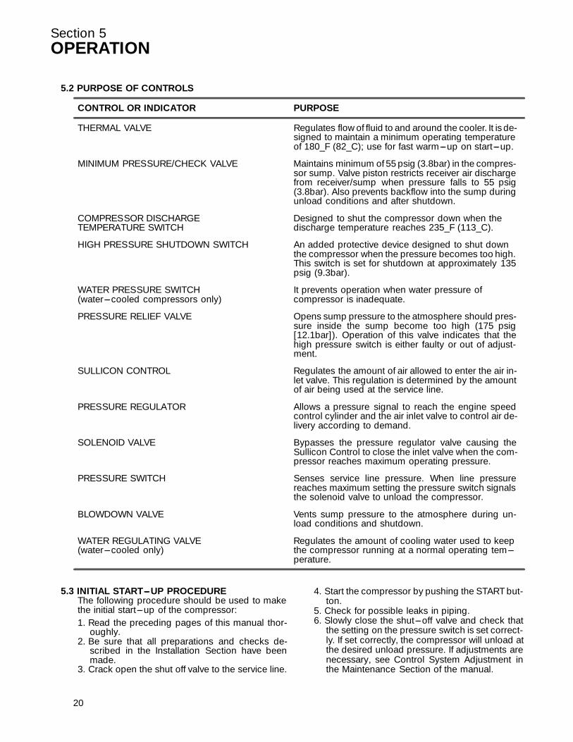
THERMAL VALVE Regulates flow of fluid to and around the cooler. It is de-signed to maintain a minimum operating temperatureof 180_F (82_C); use for fast warm---up on start---up.
MINIMUM PRESSURE/CHECK VALVE Maintains minimum of 55 psig (3.8bar) in the compres-sor sump. Valve piston restricts receiver air dischargefrom receiver/sump when pressure falls to 55 psig(3.8bar). Also prevents backflow into the sump duringunload conditions and after shutdown.
COMPRESSOR DISCHARGE Designed to shut the compressor down when theTEMPERATURE SWITCH discharge temperature reaches 235_F (113_C).
HIGH PRESSURE SHUTDOWN SWITCH An added protective device designed to shut downthe compressor when the pressure becomes too high.This switch is set for shutdown at approximately 135psig (9.3bar).
WATER PRESSURE SWITCH It prevents operation when water pressure of(water---cooled compressors only) compressor is inadequate.
PRESSURE RELIEF VALVE Opens sump pressure to the atmosphere should pres-sure inside the sump become too high (175 psig[12.1bar]). Operation of this valve indicates that thehigh pressure switch is either faulty or out of adjust-ment.
SULLICON CONTROL Regulates the amount of air allowed to enter the air in-let valve. This regulation is determined by the amountof air being used at the service line.
PRESSURE REGULATOR Allows a pressure signal to reach the engine speedcontrol cylinder and the air inlet valve to control air de-livery according to demand.
SOLENOID VALVE Bypasses the pressure regulator valve causing theSullicon Control to close the inlet valve when the com-pressor reaches maximum operating pressure.
PRESSURE SWITCH Senses service line pressure. When line pressurereaches maximum setting the pressure switch signalsthe solenoid valve to unload the compressor.
BLOWDOWN VALVE Vents sump pressure to the atmosphere during un-load conditions and shutdown.
WATER REGULATING VALVE Regulates the amount of cooling water used to keep(water---cooled only) the compressor running at a normal operating tem---
perature.
5.3 INITIAL START---UP PROCEDUREThe following procedure should be used to makethe initial start---up of the compressor:1. Read the preceding pages of this manual thor-
oughly.2. Be sure that all preparations and checks de-
scribed in the Installation Section have beenmade.
3. Crack open the shut off valve to the service line.
20
4. Start the compressor by pushing the START but-ton.
5. Check for possible leaks in piping.6. Slowly close the shut---off valve and check that
the setting on the pressure switch is set correct-ly. If set correctly, the compressor will unload atthe desired unload pressure. If adjustments arenecessary, see Control System Adjustment inthe Maintenance Section of the manual.
Section 5OPERATION
7. Observe the operating temperature. If the oper-ating temperature exceeds 200_F (93_C), thecooling system or installation environmentshould be checked.
8. Observe return line sight glasses and mainte-nance indicators.
9. Open shut---off valve to service line.10. Reinspect the compressor for temperature and
leaks the following day.
5.4 SUBSEQUENT START---UP PROCEDUREOn subsequent start---ups, check that the properlevel is visible in the fluid sight glass and simplypress the START button. When the compressor isrunning, observe the instrument panel and mainte-nance indicators.
5.5 SHUTDOWN PROCEDURETo shut the compressor down, simply press theSTOP button.
21

Section 6MAINTENANCE
6.1 GENERALAs you proceed in reading this section, it will be easyto see that the Maintenance Program for the aircompressor is quite minimal. The use of the serviceindicators provided for the bearing filter, air filter andfluid separator, will alert you when service mainte-nance is required. When the maintenance gaugeshows red, maintenance for that specific item is re-quir ed. S ee instr u c tions f or eac h item in S ec tion 6 . 7 ,Parts Replacement and Adjustment Procedures.
6.2 DAILY OPERATIONPrior to starting the compressor, it is necessary tocheck the fluid level in the sump. Should the level below, simply add the necessary amount. If the addi-tion of fluid becomes too frequent, a simple problemhas developed which is causing this excessive loss.S ee the Tr oubl eshooting S ec tion (6 . 8 ) under Ex c es -sive Fluid Consumption for a probable cause andremedy.
After a routine start has been made, observe the in-strument panel gauges and be sure they monitorthe correct reading for their particular phase of op-eration. After the compressor has warmed up, it isrecommended that a general check on the overallcompressor and instrument panel be made to as-sure that the compressor is running properly.
WARNING!
DO NOT remove caps, plugs, and/or other compo-nents when compressor is running or pressur-ized.
Stop compressor and relieve all internal pressurebefore doing so.
6.3 MAINTENANCE AFTER INITIAL 50HOURS OF OPERATIONAfter the initial 50 hours of operation, a few mainte-nance requirements are needed to clean the systemof any foreign materials. Perform the following main-tenance operations to prevent unnecessary prob-lems.
1. Clean the return line strainers.2. Clean the return line orifices.
6.4 MAINTENANCE EVERY 4000HOURSAfter 4000 hours of operation, it will be necessary toperform the following:
1. Clean the return line strainers.2. Lubricate the Sullicon Control linkage.3. Replace the fluid filter element and gasket.4. STANDARD COMPRESSORS ONLY! Drain the
sump and change the compressor fluid.
22
* Repair Kit P/N 250025---526 (40---75HP)
Figure 6---1 Fluid Filter (P/N 250025---522)
Repair Kit P/N 250025---524 (100HP)
6.5 FILTER MAINTENANCEReplace your fluid filter element and the gasket un-der any of the following conditions, whichever oc-curs first:1. As indicated by the maintenance gauge.2. Every 1000 hours.3. Every 6 months.4. STANDARD COMPRESSORS ONLY! Every
fluid change.
6.6 SEPARATOR MAINTENANCEReplace the separator elements when your separa-tor maintenance gauge shows red or after one (1)year, whichever comes first. The separator ele-ments must be replaced. DO NOT clean the separa-tor elements.
6.7 PARTS REPLACEMENT AND ADJUSTMENTPROCEDURESFLUID FILTER ELEMENT REPLACEMENTR e f e r t o F i g u r e 6 --- 1 .1. Using a strap wrench, remove the old element
and gasket.2. Clean gasket seating surface.3. Apply a light film of fluid to the new gasket.4. Hand--- tighten new element until new gasket is
seated in the gasket groove. Avoid any nicks,cuts or pinches to the gasket.
Section 6MAINTENANCE
5. Continue tightening element by hand an addition-al 1/2 to 3/4 turn.
6. Restart compressor and check for leaks.
CAUTION!
To minimize the possibility of filter element rup-ture, it is important that ONLY replacement ele-ments identified with the Sullair name, logo andappropriate part number be used and that substi-tuted elements not be used, due to the fact thatsuch filters may have inadequate or questionableworking pressure ratings.
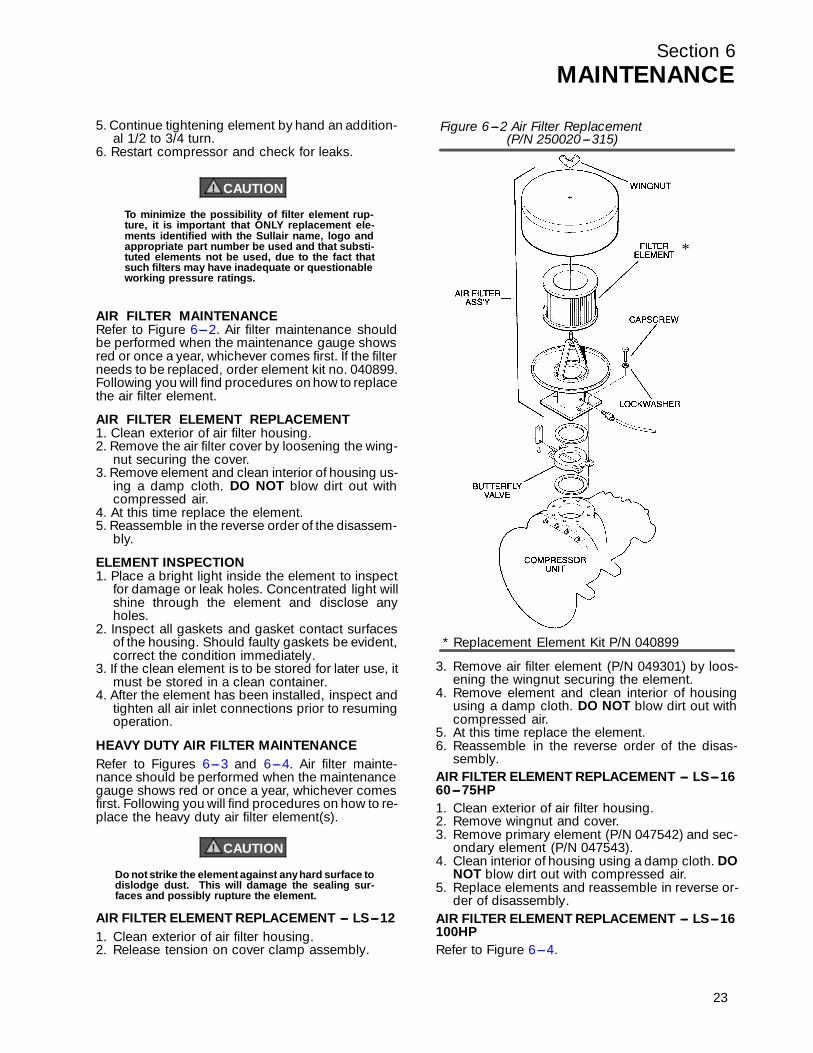
AIR FILTER MAINTENANCERef er to Figur e 6 --- 2 . A ir f il ter maintenanc e shoul dbe performed when the maintenance gauge showsred or once a year, whichever comes first. If the filterneeds to be replaced, order element kit no. 040899.Following you will find procedures on how to replacethe air filter element.
AIR FILTER ELEMENT REPLACEMENT1. Clean exterior of air filter housing.2. Remove the air filter cover by loosening the wing-
nut securing the cover.3. Remove element and clean interior of housing us-
ing a damp cloth. DO NOT blow dirt out withcompressed air.
4. At this time replace the element.5. Reassemble in the reverse order of the disassem-
bly.
ELEMENT INSPECTION1. Place a bright light inside the element to inspect
for damage or leak holes. Concentrated light willshine through the element and disclose anyholes.
2. Inspect all gaskets and gasket contact surfacesof the housing. Should faulty gaskets be evident,correct the condition immediately.
3. If the clean element is to be stored for later use, itmust be stored in a clean container.
4. After the element has been installed, inspect andtighten all air inlet connections prior to resumingoperation.
HEAVY DUTY AIR FILTER MAINTENANCER e f e r t o F i g u r e s 6 --- 3 a n d 6 --- 4 . A i r f i l t e r m a i n t e -nance should be performed when the maintenancegauge shows red or once a year, whichever comesfirst. Following you will find procedures on how to re-place the heavy duty air filter element(s).
CAUTION!
Do not strike the element against any hard surface todislodge dust. This will damage the sealing sur-faces and possibly rupture the element.
AIR FILTER ELEMENT REPLACEMENT --- LS---121. Clean exterior of air filter housing.2. Release tension on cover clamp assembly.
3. Remove air filter element (P/N 049301) by loos-ening the wingnut securing the element.
4. Remove element and clean interior of housingusing a damp cloth. DO NOT blow dirt out withcompressed air.
5. At this time replace the element.6. Reassemble in the reverse order of the disas-
sembly.AIR FILTER ELEMENT REPLACEMENT --- LS---1660---75HP1. Clean exterior of air filter housing.2. Remove wingnut and cover.3. Remove primary element (P/N 047542) and sec-
ondary element (P/N 047543).4. Clean interior of housing using a damp cloth. DO
NOT blow dirt out with compressed air.5. Replace elements and reassemble in reverse or-
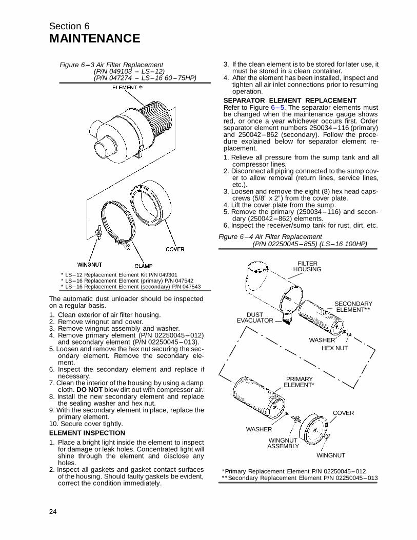
der of disassembly.AIR FILTER ELEMENT REPLACEMENT --- LS---16100HPR e f e r t o F i g u r e 6 --- 4 .
Figure 6---2 Air Filter Replacement
* Replacement Element Kit P/N 040899
(P/N 250020---315)
*
23
Section 6MAINTENANCE
The automatic dust unloader should be inspectedon a regular basis.1. Clean exterior of air filter housing.2. Remove wingnut and cover.3. Remove wingnut assembly and washer.4. Remove primary element (P/N 02250045---012)
and secondary element (P/N 02250045---013).5. Loosen and remove the hex nut securing the sec-
ondary element. Remove the secondary ele-ment.
6. Inspect the secondary element and replace ifnecessary.
7. Clean the interior of the housing by using a dampcloth. DO NOT blow dirt out with compressor air.
8. Install the new secondary element and replacethe sealing washer and hex nut.
9. With the secondary element in place, replace theprimary element.
10. Secure cover tightly.ELEMENT INSPECTION1. Place a bright light inside the element to inspect
for damage or leak holes. Concentrated light willshine through the element and disclose anyholes.
2. Inspect all gaskets and gasket contact surfacesof the housing. Should faulty gaskets be evident,correct the condition immediately.
24
3. If the clean element is to be stored for later use, itmust be stored in a clean container.
4. After the element has been installed, inspect andtighten all air inlet connections prior to resumingoperation.
SEPARATOR ELEMENT REPLACEMENTRef er to Figur e 6 --- 5 . The s epar ator el ements mustbe changed when the maintenance gauge showsred, or once a year whichever occurs first. Orderseparator element numbers 250034---116 (primary)and 250042---862 (secondary). Follow the proce-dure explained below for separator element re-placement.1. Relieve all pressure from the sump tank and all
compressor lines.2. Disconnect all piping connected to the sump cov-
er to allow removal (return lines, service lines,etc.).
3. Loosen and remove the eight (8) hex head caps-crews (5/8” x 2”) from the cover plate.
4. Lift the cover plate from the sump.5. Remove the primary (250034---116) and secon-
dary (250042---862) elements.6. Inspect the receiver/sump tank for rust, dirt, etc.
Figure 6---3 Air Filter Replacement(P/N 049103 --- LS---12)(P/N 047274 --- LS---16 60---75HP)
*
* LS---12 Replacement Element Kit P/N 049301* LS---16 Replacement Element (primary) P/N 047542* LS---16 Replacement Element (secondary) P/N 047543
Figure 6---4 Air Filter Replacement
*Primary Replacement Element P/N 02250045---012**Secondary Replacement Element P/N 02250045---013
(P/N 02250045---855) (LS---16 100HP)
DUSTEVACUATOR
SECONDARYELEMENT**
PRIMARYELEMENT*
WASHER
WINGNUT
COVER
HEX NUTWASHER
ASSEMBLY
FILTERHOUSING
WINGNUT
Section 6MAINTENANCE
7. Scrape the old gasket material from the coverand flange on the sump. Be careful not to let thescraps fall in the sump.
8. Insert the new separator elements (P/N’s250034---116 and 250042---862) into the sumptaking care not to dent them against the tankopening.
9. Clean the underside of the receiver/sump tankcover and remove any rust. Paint surface with anepoxy paint. DO NOT REMOVE GASKET STA-PLES.
10. Replace the cover plate, washers and caps-crews. Torque to 55 ft.--- lbs. (75 Nm).
11. Reconnect all piping making sure return linetubes extend to the bottom or 1/4” (6mm) abovethe bottom of the separator element. This will as-sure proper fluid return flow to the compressor.
12. Clean both return line strainers before restartingthe compressor.
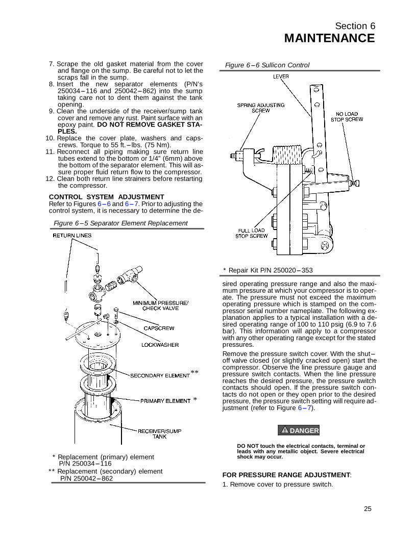
CONTROL SYSTEM ADJUSTMENTRefer to Figur es 6 --- 6 a nd 6 --- 7 . Pr ior to a djusting thecontrol system, it is necessary to determine the de-
sired operating pressure range and also the maxi-mum pressure at which your compressor is to oper-ate. The pressure must not exceed the maximumoperating pressure which is stamped on the com-pressor serial number nameplate. The following ex-planation applies to a typical installation with a de-sired operating range of 100 to 110 psig (6.9 to 7.6bar). This information will apply to a compressorwith any other operating range except for the statedpressures.Remove the pressure switch cover. With the shut---off valve closed (or slightly cracked open) start thecompressor. Observe the line pressure gauge andpressure switch contacts. When the line pressurereaches the desired pressure, the pressure switchcontacts should open. If the pressure switch con-tacts do not open or they open prior to the desiredpressure, the pressure switch setting will require ad-justment ( r ef er to Figur e 6 --- 7 ) .
DANGER!
DO NOT touch the electrical contacts, terminal orleads with any metallic object. Severe electricalshock may occur.
FOR PRESSURE RANGE ADJUSTMENT:1. Remove cover to pressure switch.
* Replacement (primary) element
** Replacement (secondary) elementP/N 250042---862
P/N 250034---116
*
**
Figure 6---5 Separator Element Replacement
* Repair Kit P/N 250020---353
Figure 6---6 Sullicon Control
25

Section 6MAINTENANCE
2. Turn the range adjusting screw to the high pres-sure setting. Turning the screw counterclockwiselowers both the high and low pressure equally.
FOR DIFFERENTIAL ADJUSTMENT:Differential is the difference between the high andlow pressure settings, 10 psig (0.7 bar) is typical.Turn the differential adjusting screw to the lower (re-set) setting. Turning the screw counterclockwise
26
widens the differential by lowering the reset (lower)setting only.When the pressure switch adjustment is complete,the pressure regulator should be adjusted for thepressure at which modulation of air delivery shouldbegin. In this case, that pressure will be 100 psig(6.9 bar). The regulator is adjusted by loosening thejam nut on the end of the cone shaped cover of thepressure regulator. With the jam nut loose, turn theadjusting screw clockwise to increase or counter-clockwise to decrease the setting.Above 100 psig (6.9 bar), the regulator should allowpressure to flow into the control chamber of the Sul-licon Control. The Sullicon Control lever should startto move at this time.Cycle the control system several times and recheckall pressure settings.
Figure 6---7 Pressure Switch (P/N 040694)
6.8 TROUBLESHOOTINGThe information contained in the Troubleshootingchart has been compiled from field report data andfactory experience. It contains symptoms and usualcauses for the described problems. However DONOT assume that these are the only problems thatmay occur. All available data concerning the troubleshould be systematically analyzed before undertak-ing any repairs or component replacement proce-dures.A detailed visual inspection is worth performing foralmost all problems and may avoid unnecessaryadditional damage to the compressor. Always re-member to:1. Check for loose wiring.2. Check for damaged piping.3. Check for parts damaged by heat or an electrical
short circuit, usually apparent by discoloration ora burnt odor.
Should your problem persist after making the rec-ommended check, consult your nearest Sullair rep-resentative or the Sullair Corporation factory.
TROUBLESHOOTING
SYMPTOM PROBABLE CAUSE REMEDY
COMPRESSOR WILL NOT START Main Disconnect Switch Open Close switch.
Line Fuse Blown Replace fuse.
Control Transformer Fuse Blown Replace fuse.
Motor Starter Overloads Tripped Reset. Should trouble persist, checkwhether motor starter contacts arefunctioning properly.
Low Incoming Line Voltage Check voltage. Should voltage check low,consult power company.
COMPRESSOR SHUTS DOWNWITH AIR DEMAND PRESENT Loss of Control Voltage Reset. If trouble persists, check that line
pressure does not exceed maximum oper---ating pressure of the compressor (specifiedon nameplate).
Section 6MAINTENANCE
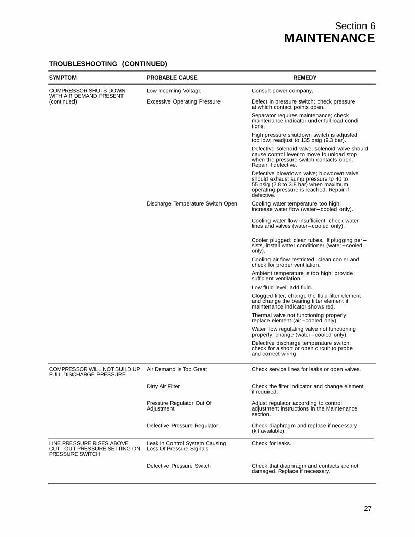
TROUBLESHOOTING (CONTINUED)
SYMPTOM PROBABLE CAUSE REMEDY
COMPRESSOR SHUTS DOWN Low Incoming Voltage Consult power company.WITH AIR DEMAND PRESENT(continued) Excessive Operating Pressure Defect in pressure switch; check pressure
at which contact points open.Separator requires maintenance; checkmaintenance indicator under full load condi---tions.High pressure shutdown switch is adjustedtoo low; readjust to 135 psig (9.3 bar).
Defective solenoid valve; solenoid valve shouldcause control lever to move to unload stopwhen the pressure switch contacts open.Repair if defective.
Defective blowdown valve; blowdown valveshould exhaust sump pressure to 40 to55 psig (2.8 to 3.8 bar) when maximumoperating pressure is reached. Repair ifdefective.
Discharge Temperature Switch Open Cooling water temperature too high;increase water flow (water---cooled only).
Cooling water flow insufficient; check waterlines and valves (water---cooled only).
Cooler plugged; clean tubes. If plugging per---sists, install water conditioner (water---cooledonly).Cooling air flow restricted; clean cooler andcheck for proper ventilation.Ambient temperature is too high; providesufficient ventilation.
Low fluid level; add fluid.Clogged filter; change the fluid filter elementand change the bearing filter element ifmaintenance indicator shows red.Thermal valve not functioning properly;replace element (air---cooled only).
Water flow regulating valve not functioningproperly; change (water---cooled only).Defective discharge temperature switch;check for a short or open circuit to probeand correct wiring.
COMPRESSOR WILL NOT BUILD UP Air Demand Is Too Great Check service lines for leaks or open valves.FULL DISCHARGE PRESSURE
Dirty Air Filter Check the filter indicator and change elementif required.
Pressure Regulator Out Of Adjust regulator according to controlAdjustment adjustment instructions in the Maintenance
section.
Defective Pressure Regulator Check diaphragm and replace if necessary(kit available).
LINE PRESSURE RISES ABOVE Leak In Control System Causing Check for leaks.CUT---OUT PRESSURE SETTING ON Loss Of Pressure SignalsPRESSURE SWITCH
Defective Pressure Switch Check that diaphragm and contacts are notdamaged. Replace if necessary.
27
Section 6MAINTENANCE
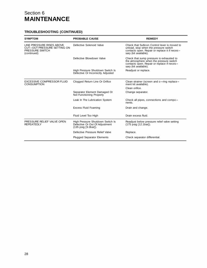
TROUBLESHOOTING (CONTINUED)
SYMPTOM PROBABLE CAUSE REMEDY
LINE PRESSURE RISES ABOVE Defective Solenoid Valve Check that Sullicon Control lever is moved toCUT---OUT PRESSURE SETTING ON unload, stop when the pressure switchPRESSURE SWITCH contacts open. Repair or replace it if neces---(continued) sary (kit available).
Defective Blowdown Valve Check that sump pressure is exhausted tothe atmosphere when the pressure switchcontacts open. Repair or replace if neces---sary (kit available).
High Pressure Shutdown Switch Is Readjust or replace.Defective Or Incorrectly Adjusted
EXCESSIVE COMPRESSOR FLUID Clogged Return Line Or Orifice Clean strainer (screen and o---ring replace---CONSUMPTION ment kit available).
Clean orifice.Separator Element Damaged Or Change separator.Not Functioning Properly
Leak In The Lubrication System Check all pipes, connections and compo---nents.
Excess Fluid Foaming Drain and change.
Fluid Level Too High Drain excess fluid.
PRESSURE RELIEF VALVE OPEN High Pressure Shutdown Switch Is Readjust below pressure relief valve settingREPEATEDLY Defective Or Out Of Adjustment (175 psig [12.1bar]).
(135 psig [9.3bar]).
Defective Pressure Relief Valve Replace.
Plugged Separator Elements Check separator differential.
28

Section 6MAINTENANCE
Figure 6---8 Piping and Instrumentation Diagram
SOLENOID
29
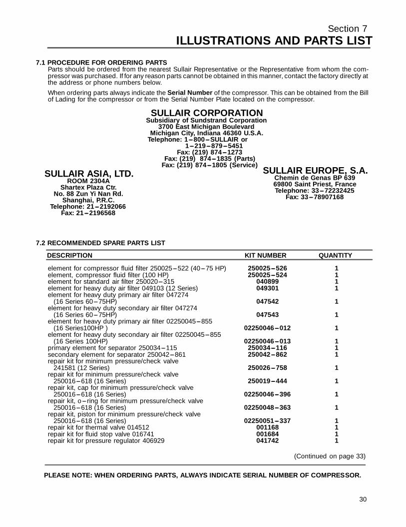
Section 7ILLUSTRATIONS AND PARTS LIST
7.1 PROCEDURE FOR ORDERING PARTSParts should be ordered from the nearest Sullair Representative or the Representative from whom the com-pressor was purchased. If for any reason parts cannot be obtained in this manner, contact the factory directly atthe address or phone numbers below.When ordering parts always indicate the Serial Number of the compressor. This can be obtained from the Billof Lading for the compressor or from the Serial Number Plate located on the compressor.
SULLAIR EUROPE, S.A.Chemin de Genas BP 63969800 Saint Priest, FranceTelephone: 33---72232425
Fax: 33---78907168
SULLAIR CORPORATIONSubsidiary of Sundstrand Corporation
3700 East Michigan BoulevardMichigan City, Indiana 46360 U.S.A.
Telephone: 1---800---SULLAIR or1---219---879---5451
Fax: (219) 874---1273
SULLAIR ASIA, LTD.ROOM 2304A
Shartex Plaza Ctr.No. 88 Zun Yi Nan Rd.
Shanghai, P.R.C.Telephone: 21---2192066
Fax: 21---2196568
Fax: (219) 874---1835 (Parts)Fax: (219) 874---1805 (Service)
7.2 RECOMMENDED SPARE PARTS LIST
DESCRIPTION KIT NUMBER QUANTITY
element for compressor fluid filter 250025---522 (40---75 HP) 250025---526 1element, compressor fluid filter (100 HP) 250025---524 1element for standard air filter 250020---315 040899 1element for heavy duty air filter 049103 (12 Series) 049301 1element for heavy duty primary air filter 047274
(16 Series 60---75HP) 047542 1element for heavy duty secondary air filter 047274
(16 Series 60---75HP) 047543 1element for heavy duty primary air filter 02250045---855
(16 Series100HP ) 02250046---012 1element for heavy duty secondary air filter 02250045---855
(16 Series 100HP) 02250046---013 1primary element for separator 250034---115 250034---116 1secondary element for separator 250042---861 250042---862 1repair kit for minimum pressure/check valve
241581 (12 Series) 250026---758 1repair kit for minimum pressure/check valve
250016---618 (16 Series) 250019---444 1repair kit, cap for minimum pressure/check valve
250016---618 (16 Series) 02250046---396 1repair kit, o---ring for minimum pressure/check valve
250016---618 (16 Series) 02250048---363 1repair kit, piston for minimum pressure/check valve
250016---618 (16 Series) 02250051---337 1repair kit for thermal valve 014512 001168 1repair kit for fluid stop valve 016741 001684 1repair kit for pressure regulator 406929 041742 1
(Continued on page 33)
PLEASE NOTE: WHEN ORDERING PARTS, ALWAYS INDICATE SERIAL NUMBER OF COMPRESSOR.
30
Section 7ILLUSTRATIONS AND PARTS LIST
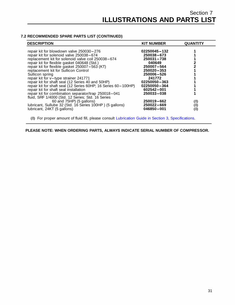
7.2 RECOMMENDED SPARE PARTS LIST (CONTINUED)
DESCRIPTION KIT NUMBER QUANTITY
repair kit for blowdown valve 250030---276 02250045---132 1repair kit for solenoid valve 250038---674 250038---673 1replacement kit for solenoid valve coil 250038---674 250031---738 1repair kit for flexible gasket 040648 (Std.) 040649 2repair kit for flexible gasket 250007---563 (KT) 250007---564 2replacement kit for Sullicon Control 250020---353 1Sullicon spring 250006---526 1repair kit for v--- type strainer 241771 241772 1repair kit for shaft seal (12 Series 40 and 50HP) 02250050---363 1repair kit for shaft seal (12 Series 60HP; 16 Series 60---100HP) 02250050---364 1repair kit for shaft seal installation 602542---001 1repair kit for combination separator/trap 250018---041 250033---038 1fluid, SRF 1/4000 (Std. 12 Series; Std. 16 Series
60 and 75HP) (5 gallons) 250019---662 (I)lubricant, Sullube 32 (Std. 16 Series 100HP ) (5 gallons) 250022---669 (I)lubricant, 24KT (5 gallons) 046850---001 (I)
(I) For pr oper a mount of fl uid f il l , pl ease c onsul t Lubr ic a tion Guide in S ec tion 3 , S pec ific ations.
PLEASE NOTE: WHEN ORDERING PARTS, ALWAYS INDICATE SERIAL NUMBER OF COMPRESSOR.
31
Section 7ILLUSTRATIONS AND PARTS LIST
32
NOTES
Section 7ILLUSTRATIONS AND PARTS LIST
7.3 MOTOR, FRAME, COMPRESSOR AND PARTS (LS---12 SERIES)
33
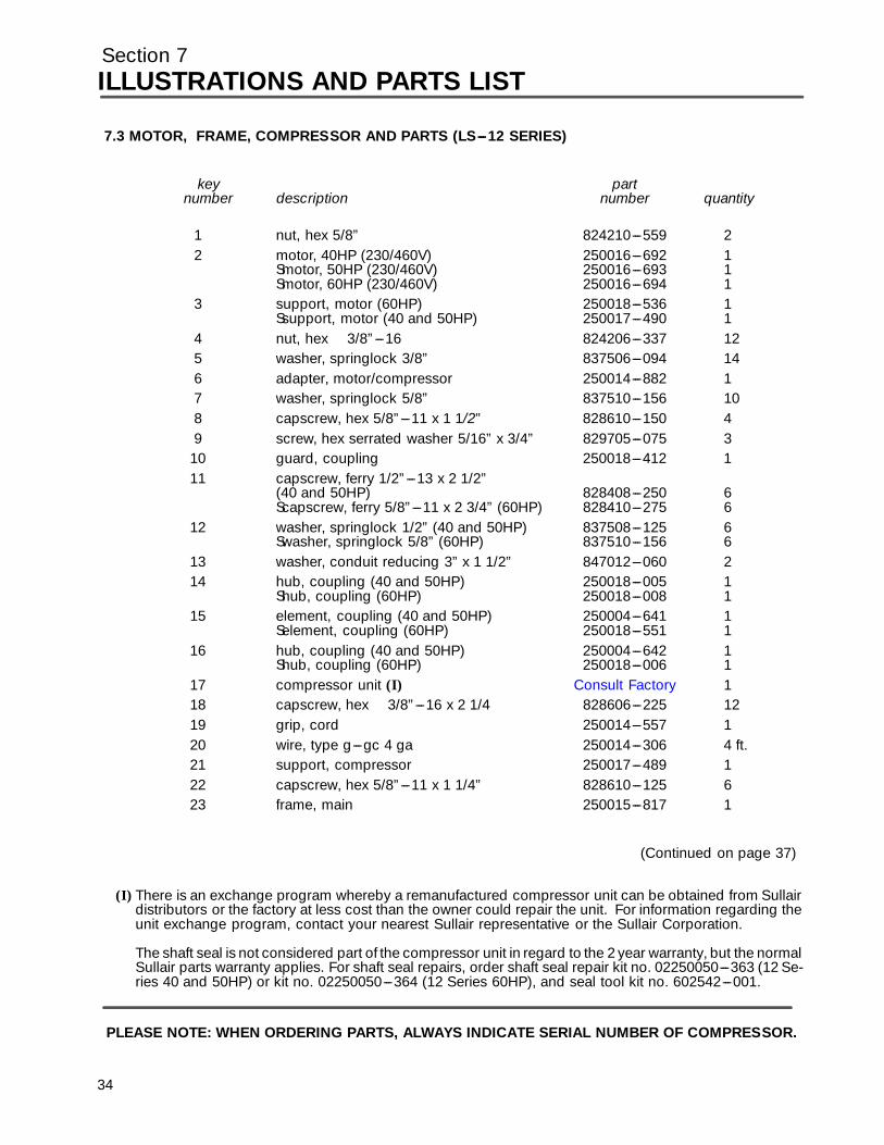
Section 7ILLUSTRATIONS AND PARTS LIST
7.3 MOTOR, FRAME, COMPRESSOR AND PARTS (LS---12 SERIES)
key partnumber description number quantity
1 nut, hex 5/8” 824210---559 22 motor, 40HP (230/460V) 250016---692 1
Smotor, 50HP (230/460V) 250016---693 1Smotor, 60HP (230/460V) 250016---694 1
3 support, motor (60HP) 250018---536 1Ssupport, motor (40 and 50HP) 250017---490 1
4 nut, hex 3/8”---16 824206---337 125 washer, springlock 3/8” 837506---094 146 adapter, motor/compressor 250014---882 17 washer, springlock 5/8” 837510---156 108 capscrew, hex 5/8”---11 x 1 1/2” 828610---150 49 screw, hex serrated washer 5/16” x 3/4” 829705---075 3
10 guard, coupling 250018---412 111 capscrew, ferry 1/2”---13 x 2 1/2”
(40 and 50HP) 828408---250 6Scapscrew, ferry 5/8”---11 x 2 3/4” (60HP) 828410---275 6
12 washer, springlock 1/2” (40 and 50HP) 837508---125 6Swasher, springlock 5/8” (60HP) 837510---156 6
13 washer, conduit reducing 3” x 1 1/2” 847012---060 214 hub, coupling (40 and 50HP) 250018---005 1
Shub, coupling (60HP) 250018---008 115 element, coupling (40 and 50HP) 250004---641 1
Selement, coupling (60HP) 250018---551 116 hub, coupling (40 and 50HP) 250004---642 1
Shub, coupling (60HP) 250018---006 11 7 c ompr essor unit (I) Consul t Fac tor y 118 capscrew, hex 3/8”---16 x 2 1/4 828606---225 1219 grip, cord 250014---557 120 wire, type g---gc 4 ga 250014---306 4 ft.21 support, compressor 250017---489 122 capscrew, hex 5/8”---11 x 1 1/4” 828610---125 623 frame, main 250015---817 1
(Continued on page 37)
(I) There is an exchange program whereby a remanufactured compressor unit can be obtained from Sullairdistributors or the factory at less cost than the owner could repair the unit. For information regarding theunit exchange program, contact your nearest Sullair representative or the Sullair Corporation.
The shaft seal is not considered part of the compressor unit in regard to the 2 year warranty, but the normalSullair parts warranty applies. For shaft seal repairs, order shaft seal repair kit no. 02250050---363 (12 Se-ries 40 and 50HP) or kit no. 02250050---364 (12 Series 60HP), and seal tool kit no. 602542---001.
PLEASE NOTE: WHEN ORDERING PARTS, ALWAYS INDICATE SERIAL NUMBER OF COMPRESSOR.
34

Section 7ILLUSTRATIONS AND PARTS LIST
35
7.3 MOTOR, FRAME, COMPRESSOR AND PARTS (LS---12 SERIES)
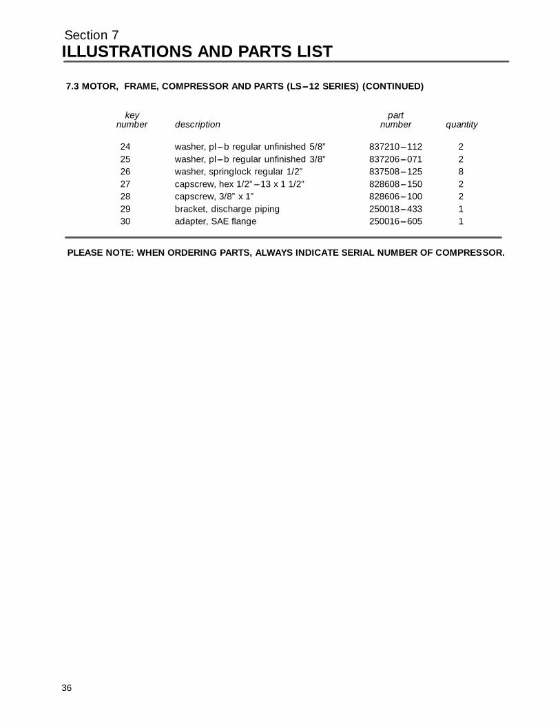
Section 7ILLUSTRATIONS AND PARTS LIST
7.3 MOTOR, FRAME, COMPRESSOR AND PARTS (LS---12 SERIES) (CONTINUED)
key partnumber description number quantity
24 washer, pl---b regular unfinished 5/8” 837210---112 225 washer, pl---b regular unfinished 3/8” 837206---071 226 washer, springlock regular 1/2” 837508---125 827 capscrew, hex 1/2”---13 x 1 1/2” 828608---150 228 capscrew, 3/8” x 1” 828606---100 229 bracket, discharge piping 250018---433 130 adapter, SAE flange 250016---605 1
PLEASE NOTE: WHEN ORDERING PARTS, ALWAYS INDICATE SERIAL NUMBER OF COMPRESSOR.
36

Section 7ILLUSTRATIONS AND PARTS LIST
7.4 MOTOR, FRAME, COMPRESSOR AND PARTS (LS---16 SERIES 60---75HP)
37
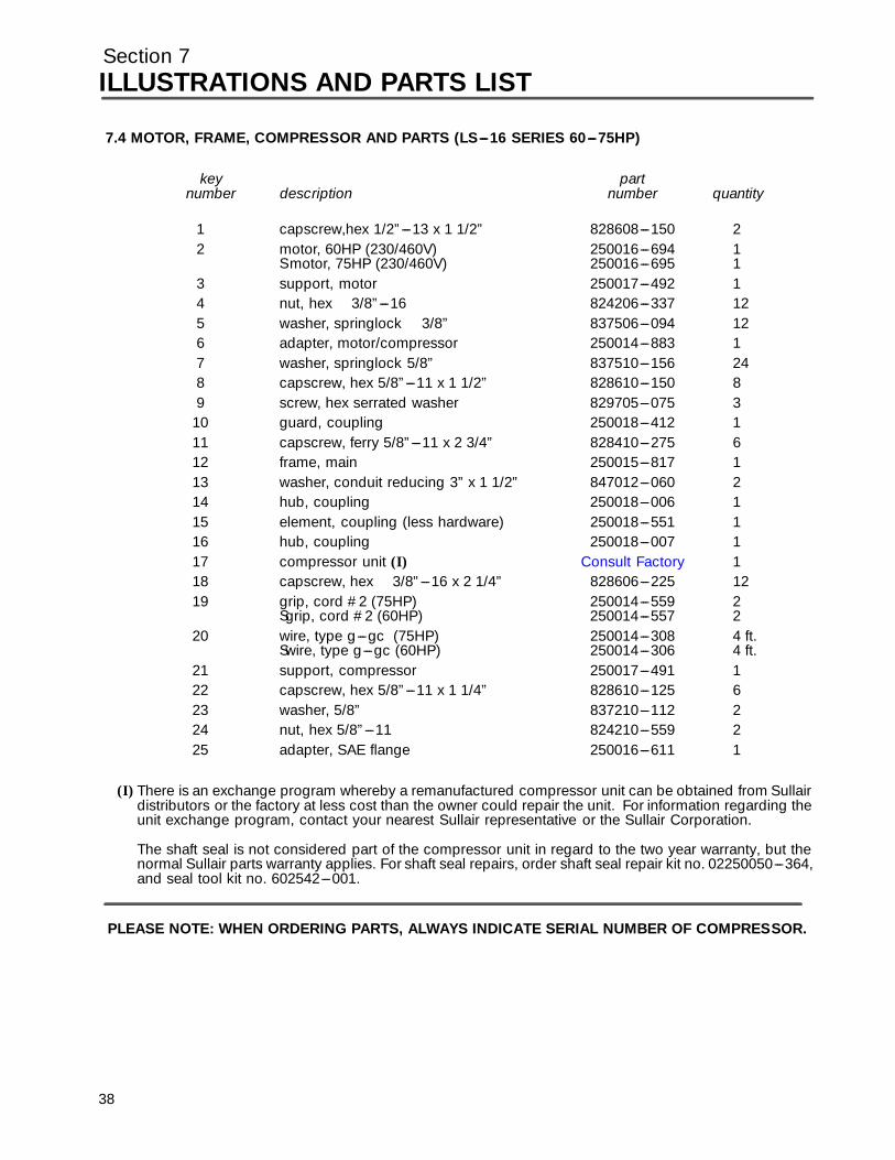
Section 7ILLUSTRATIONS AND PARTS LIST
7.4 MOTOR, FRAME, COMPRESSOR AND PARTS (LS---16 SERIES 60---75HP)
key partnumber description number quantity
1 capscrew,hex 1/2”---13 x 1 1/2” 828608---150 22 motor, 60HP (230/460V) 250016---694 1
S motor, 75HP (230/460V) 250016---695 13 support, motor 250017---492 14 nut, hex 3/8”---16 824206---337 125 washer, springlock 3/8” 837506---094 126 adapter, motor/compressor 250014---883 17 washer, springlock 5/8” 837510---156 248 capscrew, hex 5/8”---11 x 1 1/2” 828610---150 89 screw, hex serrated washer 829705---075 3
10 guard, coupling 250018---412 111 capscrew, ferry 5/8”---11 x 2 3/4” 828410---275 612 frame, main 250015---817 113 washer, conduit reducing 3” x 1 1/2” 847012---060 214 hub, coupling 250018---006 115 element, coupling (less hardware) 250018---551 116 hub, coupling 250018---007 11 7 c ompr essor unit (I) Consul t Fac tor y 118 capscrew, hex 3/8”---16 x 2 1/4” 828606---225 1219 grip, cord #2 (75HP) 250014---559 2
Sgrip, cord #2 (60HP) 250014---557 220 wire, type g---gc (75HP) 250014---308 4 ft.
Swire, type g---gc (60HP) 250014---306 4 ft.21 support, compressor 250017---491 122 capscrew, hex 5/8”---11 x 1 1/4” 828610---125 623 washer, 5/8” 837210---112 224 nut, hex 5/8”---11 824210---559 225 adapter, SAE flange 250016---611 1
(I) There is an exchange program whereby a remanufactured compressor unit can be obtained from Sullairdistributors or the factory at less cost than the owner could repair the unit. For information regarding theunit exchange program, contact your nearest Sullair representative or the Sullair Corporation.
The shaft seal is not considered part of the compressor unit in regard to the two year warranty, but thenormal Sullair parts warranty applies. For shaft seal repairs, order shaft seal repair kit no. 02250050---364,and seal tool kit no. 602542---001.
PLEASE NOTE: WHEN ORDERING PARTS, ALWAYS INDICATE SERIAL NUMBER OF COMPRESSOR.
38
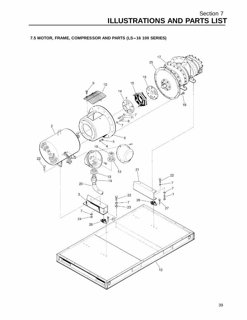
Section 7ILLUSTRATIONS AND PARTS LIST
7.5 MOTOR, FRAME, COMPRESSOR AND PARTS (LS---16 100 SERIES)
39
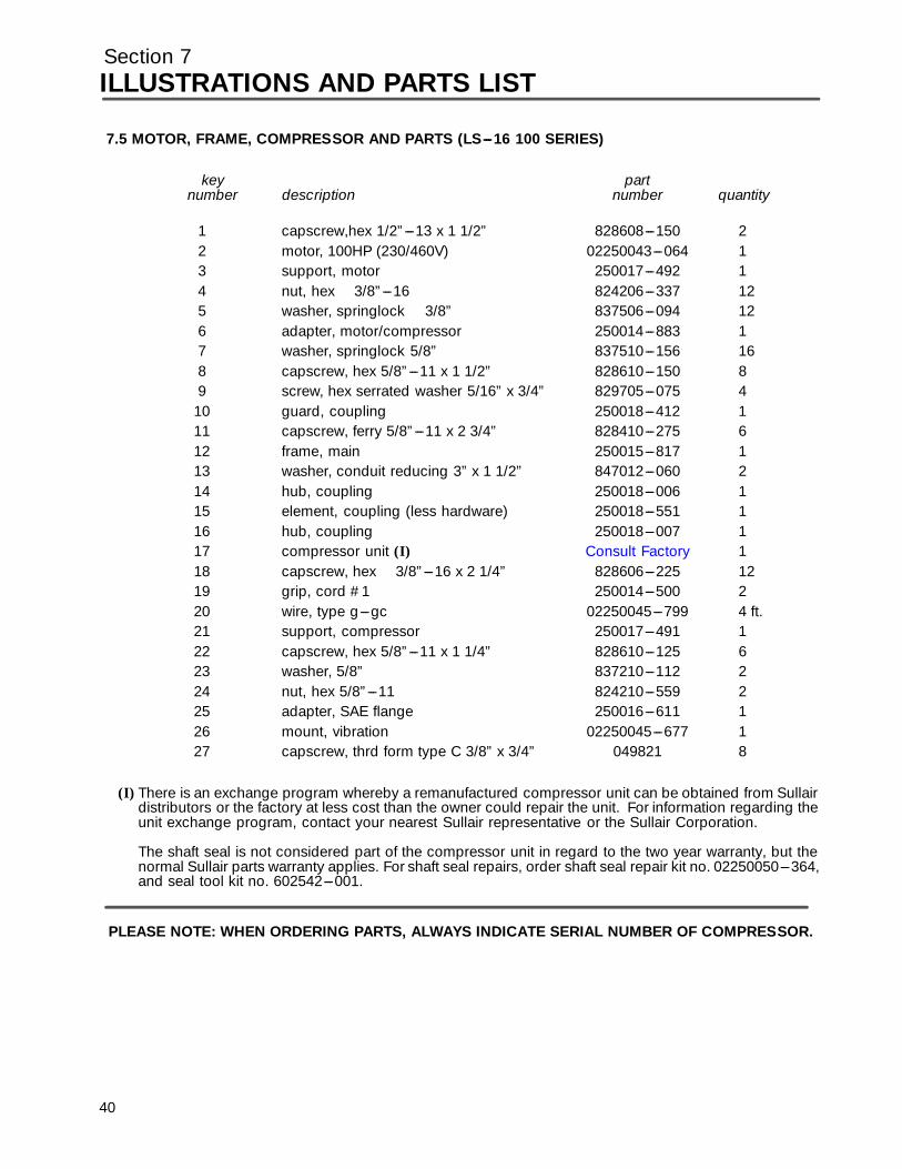
Section 7ILLUSTRATIONS AND PARTS LIST
7.5 MOTOR, FRAME, COMPRESSOR AND PARTS (LS---16 100 SERIES)
key partnumber description number quantity
1 capscrew,hex 1/2”---13 x 1 1/2” 828608---150 22 motor, 100HP (230/460V) 02250043---064 13 support, motor 250017---492 14 nut, hex 3/8”---16 824206---337 125 washer, springlock 3/8” 837506---094 126 adapter, motor/compressor 250014---883 17 washer, springlock 5/8” 837510---156 168 capscrew, hex 5/8”---11 x 1 1/2” 828610---150 89 screw, hex serrated washer 5/16” x 3/4” 829705---075 4
10 guard, coupling 250018---412 111 capscrew, ferry 5/8”---11 x 2 3/4” 828410---275 612 frame, main 250015---817 113 washer, conduit reducing 3” x 1 1/2” 847012---060 214 hub, coupling 250018---006 115 element, coupling (less hardware) 250018---551 116 hub, coupling 250018---007 11 7 c ompr essor unit (I) Consul t Fac tor y 118 capscrew, hex 3/8”---16 x 2 1/4” 828606---225 1219 grip, cord #1 250014---500 220 wire, type g---gc 02250045---799 4 ft.21 support, compressor 250017---491 122 capscrew, hex 5/8”---11 x 1 1/4” 828610---125 623 washer, 5/8” 837210---112 224 nut, hex 5/8”---11 824210---559 225 adapter, SAE flange 250016---611 126 mount, vibration 02250045---677 127 capscrew, thrd form type C 3/8” x 3/4” 049821 8
(I) There is an exchange program whereby a remanufactured compressor unit can be obtained from Sullairdistributors or the factory at less cost than the owner could repair the unit. For information regarding theunit exchange program, contact your nearest Sullair representative or the Sullair Corporation.
The shaft seal is not considered part of the compressor unit in regard to the two year warranty, but thenormal Sullair parts warranty applies. For shaft seal repairs, order shaft seal repair kit no. 02250050---364,and seal tool kit no. 602542---001.
PLEASE NOTE: WHEN ORDERING PARTS, ALWAYS INDICATE SERIAL NUMBER OF COMPRESSOR.
40
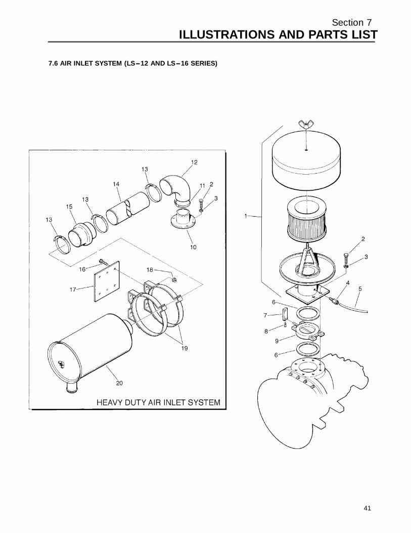
Section 7ILLUSTRATIONS AND PARTS LIST
7.6 AIR INLET SYSTEM (LS---12 AND LS---16 SERIES)
41

Section 7ILLUSTRATIONS AND PARTS LIST
7.6 AIR INLET SYSTEM (LS---12 AND LS---16 SERIES)
key partnumber description number quantity
1 filter, assembly air (with flanged base) (I) 250020---315 12 capscrew, hex 1/2 ”---13 x 2 1/2” 828608---250 43 washer, springlock 1/2” 837508---125 44 connector, tube---straight 1/8”npt x 1/4”t 813604---125 15 tubing, thermoplastic 1/4”od 250024---745 7 ft.6 gasket,1/32 ” x 51/4!”od x 4 1/8”id 040708 27 lever, inlet valve 020687 18 screw, set 5/16”---18 x 3/4 ” 408383 19 valve, butterfly 4” 040640 1
10 adapter, compressor inlet assy 02250046---257 111 clamp, hose 040642 112 elbow, rubber reducing 4” x 5” 047275 113 clamp, hose 6” 408153 314 tube, aluminum 5” x 23” 02250046---003 115 hose, hump 5” 02250045---989 116 screw, hex serrated wash 5/16” x 3/4” 829705---07517 support, bracket filter 02250046---997 118 nut, hex flanged 5/16”---18 825305---283 119 band, mounting 12” 040081 220 filter, assy air (16 Series 100HP) (II) 02250045---855 1
Sfilter, assy air (12 Series 40 and 50HP) (III) 049103 1Sfilter, assy air (12 Series 60HP;16 Series 60 and 75HP) (IV) 047274 1
(I) For maintenance on air filter assembly no. 250020---315, order element no. 040899.
(II) For maintenance on air filter assy no. 02250045---855, order primary element no. 02250046---012, andsafety element no. 02250046---013.
(III) For maintenance on air filter assembly no. 049103, order element no. 049301.
(IV) For maintenance on air filter assembly no. 047274, order primary element no. 047542 and safety elementno. 047543.
PLEASE NOTE: WHEN ORDERING PARTS, ALWAYS INDICATE SERIAL NUMBER OF COMPRESSOR.
42
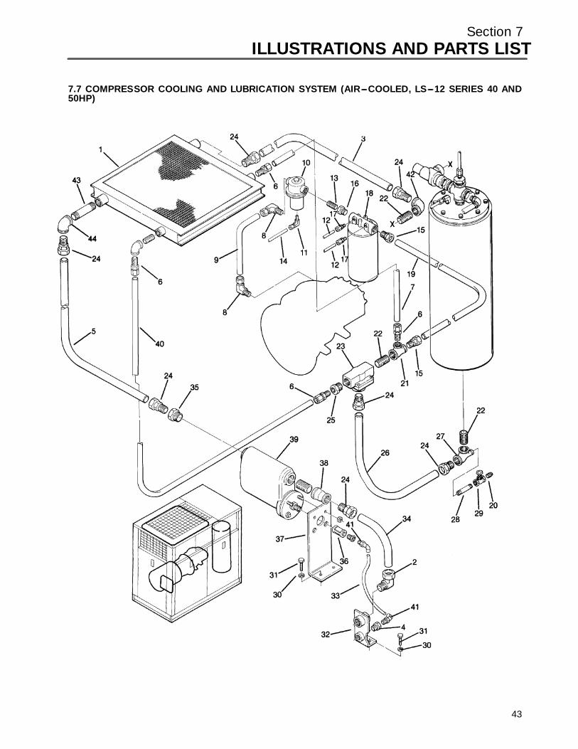
Section 7ILLUSTRATIONS AND PARTS LIST
7.7 COMPRESSOR COOLING AND LUBRICATION SYSTEM (AIR---COOLED, LS---12 SERIES 40 AND50HP)
43

Section 7ILLUSTRATIONS AND PARTS LIST
7.7 COMPRESSOR COOLING AND LUBRICATION SYSTEM (AIR---COOLED, LS---12 SERIES 40 AND50HP)
key partnumber description number quantity
1 cooler, fluid and aftercooler assembly 250038---657 12 elbow, tube---m 1 1/2” x 1 1/2” 810524---150 13 tube, 1 1/2” 250018---259 14 bushing, reducing 3/4” x 1/2” 802103---020 15 tube, 1 1/2”od 250018---251 16 connector, tube 1” x 1” 810216---100 37 tube, 1” 250039---986 18 elbow, tube 1” x 1” 810516---100 39 tube, 1” 250038---497 1
10 valve, fluid stop 1” (I) 016741 111 elbow, tube 5/16” x 1/4” 810505---025 112 tubing, 1/4” 841015---004 10 ft.13 nipple, pipe 1” x close 822216---000 314 tubing, 5/16” stainless steel 841215---005 2.7 ft.15 connector, tube---m 1 1/4” x 1 1/4” 810220---125 216 bushing, reducing 1 1/4” x 1” 802105---040 117 connector, tube---m 1/4” x 1/4” 810204---025 218 filter, fluid (II) 250025---522 119 tube, 1 1/4” 250018---246 120 plug, pipe 1/2” 807800---020 121 tee, reducing 1 1/2” x 1 1/4” x 1” 802206---054 122 nipple, pipe 1 1/2” x close 822224---000 223 valve, thermal (III) 014512 124 connector, tube---m 1 1/2” x 1 1/2” 810224---150 725 bushing, reducing 1 1/2” x 1” 802106---040 126 tube, 1 1/2” 250018---376 127 tee, reducing 1 1/2” x 1/2” x 1 1/2” 802206---026 128 nipple, pipe 1/2” x 4” 822108---040 129 valve, globe 1/2” 041007 130 washer, springlock 1/2” 837508---125 331 capscrew, hex 1/2”---13 gr5 828608---150 332 bracket, air connector and condenser drain 250017---233 1
(Continued on page 47)
(I) For maintenance on fluid stop valve no. 016741, order repair kit no. 001684.
(II) For maintenance on fluid filter no. 250025---522, order repair kit no. 250025---526.
(III) For maintenance on thermal valve no. 014512, order repair kit no. 001168.
PLEASE NOTE: WHEN ORDERING PARTS, ALWAYS INDICATE SERIAL NUMBER OF COMPRESSOR.
44

Section 7ILLUSTRATIONS AND PARTS LIST
45
7.7 COMPRESSOR COOLING AND LUBRICATION SYSTEM (AIR---COOLED, LS---12 SERIES 40 AND50HP)
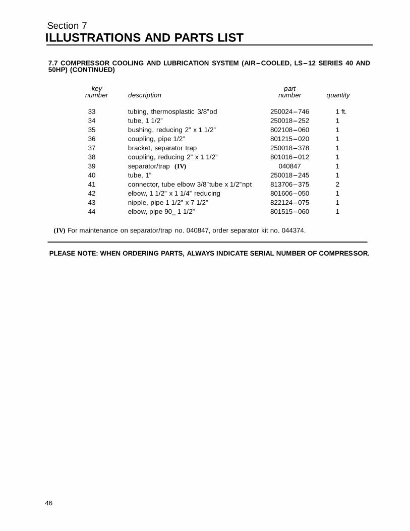
Section 7ILLUSTRATIONS AND PARTS LIST
7.7 COMPRESSOR COOLING AND LUBRICATION SYSTEM (AIR---COOLED, LS---12 SERIES 40 AND50HP) (CONTINUED)
key partnumber description number quantity
33 tubing, thermosplastic 3/8”od 250024---746 1 ft.34 tube, 1 1/2” 250018---252 135 bushing, reducing 2” x 1 1/2” 802108---060 136 coupling, pipe 1/2” 801215---020 137 bracket, separator trap 250018---378 138 coupling, reducing 2” x 1 1/2” 801016---012 139 separator/trap (IV) 040847 140 tube, 1” 250018---245 141 connector, tube elbow 3/8”tube x 1/2”npt 813706---375 242 elbow, 1 1/2” x 1 1/4” reducing 801606---050 143 nipple, pipe 1 1/2” x 7 1/2” 822124---075 144 elbow, pipe 90_ 1 1/2” 801515---060 1
(IV) For maintenance on separator/trap no. 040847, order separator kit no. 044374.
PLEASE NOTE: WHEN ORDERING PARTS, ALWAYS INDICATE SERIAL NUMBER OF COMPRESSOR.
46

Section 7ILLUSTRATIONS AND PARTS LIST
7.8 COMPRESSOR COOLING AND LUBRICATION SYSTEM (WATER---COOLED, LS---12 SERIES 40 AND50HP)
47
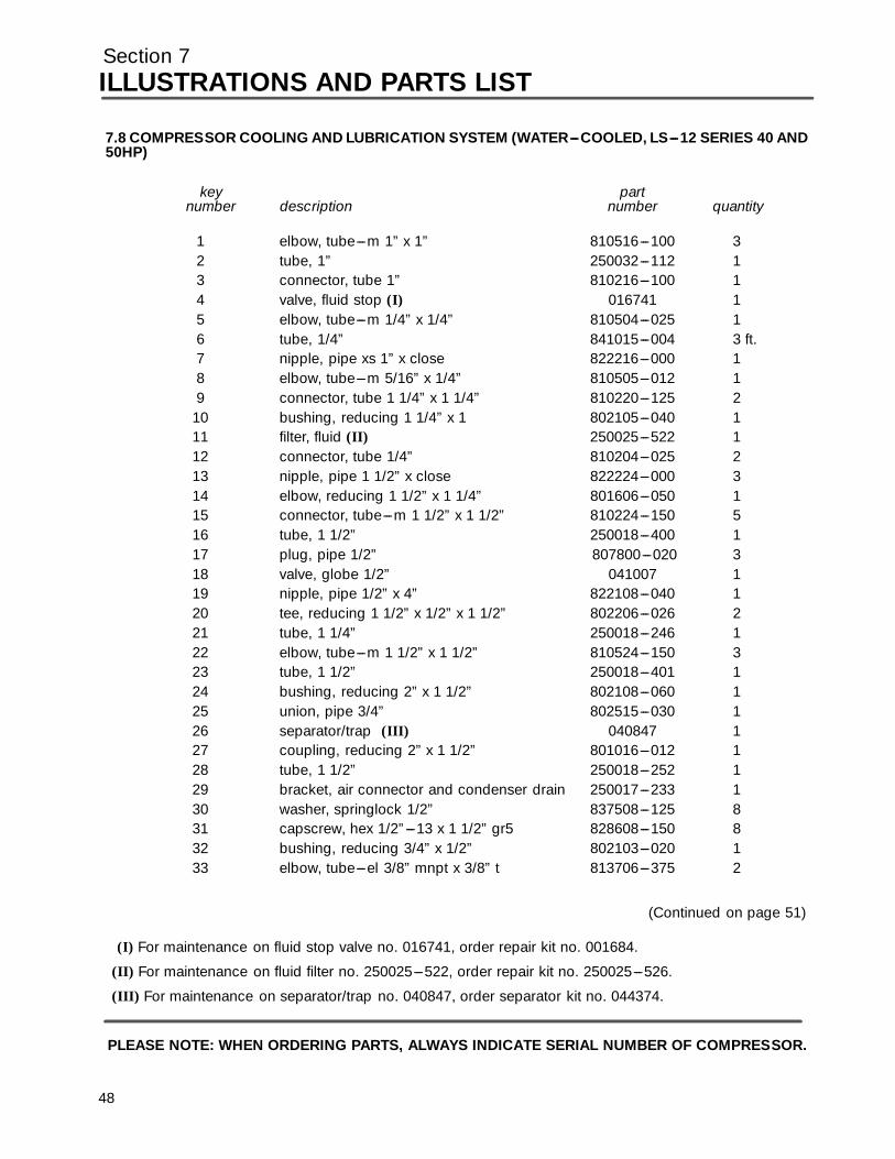
Section 7ILLUSTRATIONS AND PARTS LIST
7.8 COMPRESSOR COOLING AND LUBRICATION SYSTEM (WATER---COOLED, LS---12 SERIES 40 AND50HP)
key partnumber description number quantity
1 elbow, tube---m 1” x 1” 810516---100 32 tube, 1” 250032---112 13 connector, tube 1” 810216---100 14 valve, fluid stop (I) 016741 15 elbow, tube---m 1/4” x 1/4” 810504---025 16 tube, 1/4” 841015---004 3 ft.7 nipple, pipe xs 1” x close 822216---000 18 elbow, tube---m 5/16” x 1/4” 810505---012 19 connector, tube 1 1/4” x 1 1/4” 810220---125 2
10 bushing, reducing 1 1/4” x 1 802105---040 111 filter, fluid (II) 250025---522 112 connector, tube 1/4” 810204---025 213 nipple, pipe 1 1/2” x close 822224---000 314 elbow, reducing 1 1/2” x 1 1/4” 801606---050 115 connector, tube---m 1 1/2” x 1 1/2” 810224---150 516 tube, 1 1/2” 250018---400 117 plug, pipe 1/2” 807800---020 318 valve, globe 1/2” 041007 119 nipple, pipe 1/2” x 4” 822108---040 120 tee, reducing 1 1/2” x 1/2” x 1 1/2” 802206---026 221 tube, 1 1/4” 250018---246 122 elbow, tube---m 1 1/2” x 1 1/2” 810524---150 323 tube, 1 1/2” 250018---401 124 bushing, reducing 2” x 1 1/2” 802108---060 125 union, pipe 3/4” 802515---030 126 separator/trap (III) 040847 127 coupling, reducing 2” x 1 1/2” 801016---012 128 tube, 1 1/2” 250018---252 129 bracket, air connector and condenser drain 250017---233 130 washer, springlock 1/2” 837508---125 831 capscrew, hex 1/2”---13 x 1 1/2” gr5 828608---150 832 bushing, reducing 3/4” x 1/2” 802103---020 133 elbow, tube---el 3/8” mnpt x 3/8” t 813706---375 2
(Continued on page 51)
(I) For maintenance on fluid stop valve no. 016741, order repair kit no. 001684.
(II) For maintenance on fluid filter no. 250025---522, order repair kit no. 250025---526.
(III) For maintenance on separator/trap no. 040847, order separator kit no. 044374.
PLEASE NOTE: WHEN ORDERING PARTS, ALWAYS INDICATE SERIAL NUMBER OF COMPRESSOR.
48
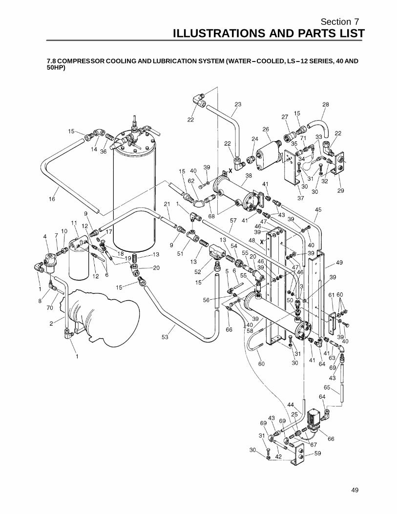
Section 7ILLUSTRATIONS AND PARTS LIST
49
7.8 COMPRESSOR COOLING AND LUBRICATION SYSTEM (WATER---COOLED, LS---12 SERIES, 40 AND50HP)
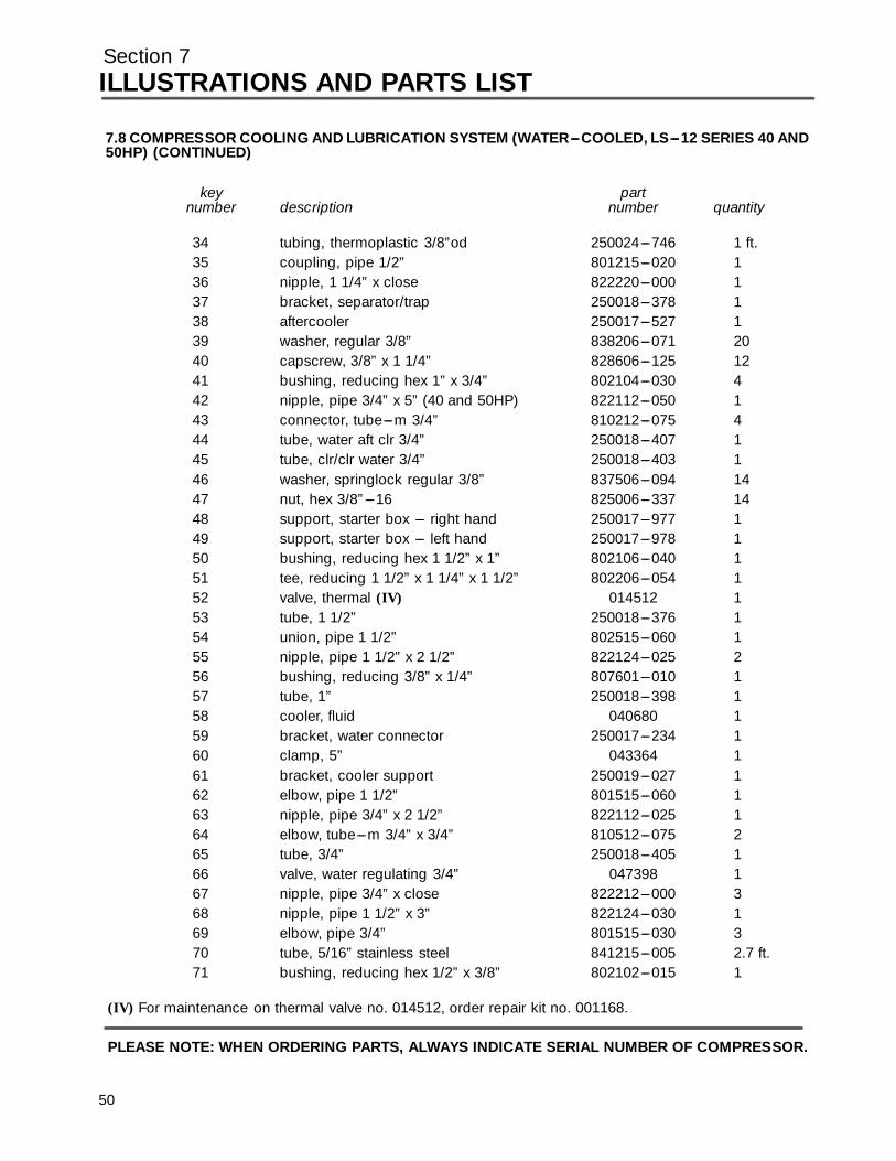
Section 7ILLUSTRATIONS AND PARTS LIST
7.8 COMPRESSOR COOLING AND LUBRICATION SYSTEM (WATER---COOLED, LS---12 SERIES 40 AND50HP) (CONTINUED)
key partnumber description number quantity
34 tubing, thermoplastic 3/8”od 250024---746 1 ft.35 coupling, pipe 1/2” 801215---020 136 nipple, 1 1/4” x close 822220---000 137 bracket, separator/trap 250018---378 138 aftercooler 250017---527 139 washer, regular 3/8” 838206---071 2040 capscrew, 3/8” x 1 1/4” 828606---125 1241 bushing, reducing hex 1” x 3/4” 802104---030 442 nipple, pipe 3/4” x 5” (40 and 50HP) 822112---050 143 connector, tube---m 3/4” 810212---075 444 tube, water aft clr 3/4” 250018---407 145 tube, clr/clr water 3/4” 250018---403 146 washer, springlock regular 3/8” 837506---094 1447 nut, hex 3/8”---16 825006---337 1448 support, starter box --- right hand 250017---977 149 support, starter box --- left hand 250017---978 150 bushing, reducing hex 1 1/2” x 1” 802106---040 151 tee, reducing 1 1/2” x 1 1/4” x 1 1/2” 802206---054 152 valve, thermal (IV) 014512 153 tube, 1 1/2” 250018---376 154 union, pipe 1 1/2” 802515---060 155 nipple, pipe 1 1/2” x 2 1/2” 822124---025 256 bushing, reducing 3/8” x 1/4” 807601---010 157 tube, 1” 250018---398 158 cooler, fluid 040680 159 bracket, water connector 250017---234 160 clamp, 5” 043364 161 bracket, cooler support 250019---027 162 elbow, pipe 1 1/2” 801515---060 163 nipple, pipe 3/4” x 2 1/2” 822112---025 164 elbow, tube---m 3/4” x 3/4” 810512---075 265 tube, 3/4” 250018---405 166 valve, water regulating 3/4” 047398 167 nipple, pipe 3/4” x close 822212---000 368 nipple, pipe 1 1/2” x 3” 822124---030 169 elbow, pipe 3/4” 801515---030 370 tube, 5/16” stainless steel 841215---005 2.7 ft.71 bushing, reducing hex 1/2” x 3/8” 802102---015 1
(IV) For maintenance on thermal valve no. 014512, order repair kit no. 001168.
PLEASE NOTE: WHEN ORDERING PARTS, ALWAYS INDICATE SERIAL NUMBER OF COMPRESSOR.
50

Section 7ILLUSTRATIONS AND PARTS LIST
7.9 COMPRESSOR COOLING AND LUBRICATION SYSTEM (AIR---COOLED, LS---12 SERIES 60HP, ANDLS---16 SERIES 60---75HP)
51
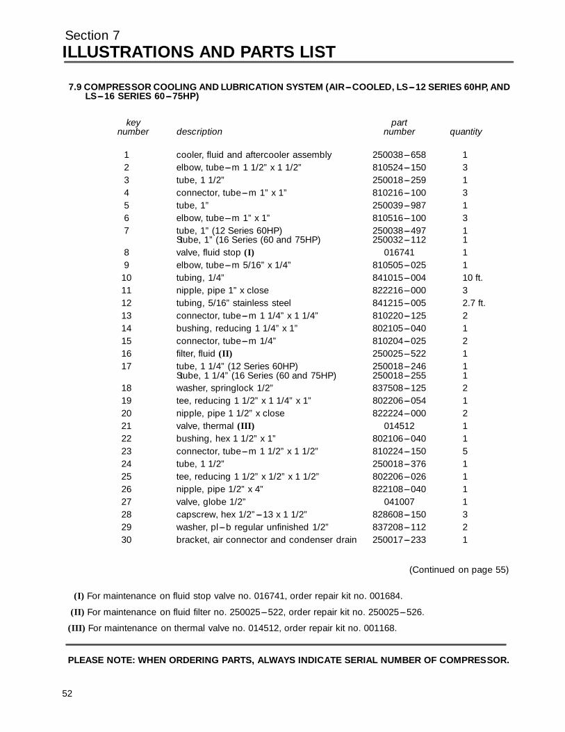
Section 7ILLUSTRATIONS AND PARTS LIST
5
7.9 COMPRESSOR COOLING AND LUBRICATION SYSTEM (AIR---COOLED, LS---12 SERIES 60HP, ANDLS---16 SERIES 60---75HP)
key partnumber description number quantity
1 cooler, fluid and aftercooler assembly 250038---658 12 elbow, tube---m 1 1/2” x 1 1/2” 810524---150 33 tube, 1 1/2” 250018---259 14 connector, tube---m 1” x 1” 810216---100 35 tube, 1” 250039---987 16 elbow, tube---m 1” x 1” 810516---100 37 tube, 1” (12 Series 60HP) 250038---497 1
Stube, 1” (16 Series (60 and 75HP) 250032---112 18 valve, fluid stop (I) 016741 19 elbow, tube---m 5/16” x 1/4” 810505---025 1
10 tubing, 1/4” 841015---004 10 ft.11 nipple, pipe 1” x close 822216---000 312 tubing, 5/16” stainless steel 841215---005 2.7 ft.13 connector, tube---m 1 1/4” x 1 1/4” 810220---125 214 bushing, reducing 1 1/4” x 1” 802105---040 115 connector, tube---m 1/4” 810204---025 216 filter, fluid (II) 250025---522 117 tube, 1 1/4” (12 Series 60HP) 250018---246 1
Stube, 1 1/4” (16 Series (60 and 75HP) 250018---255 118 washer, springlock 1/2” 837508---125 219 tee, reducing 1 1/2” x 1 1/4” x 1” 802206---054 120 nipple, pipe 1 1/2” x close 822224---000 221 valve, thermal (III) 014512 122 bushing, hex 1 1/2” x 1” 802106---040 123 connector, tube---m 1 1/2” x 1 1/2” 810224---150 524 tube, 1 1/2” 250018---376 125 tee, reducing 1 1/2” x 1/2” x 1 1/2” 802206---026 126 nipple, pipe 1/2” x 4” 822108---040 127 valve, globe 1/2” 041007 128 capscrew, hex 1/2”---13 x 1 1/2” 828608---150 329 washer, pl---b regular unfinished 1/2” 837208---112 230 bracket, air connector and condenser drain 250017---233 1
(Continued on page 55)
(I) For maintenance on fluid stop valve no. 016741, order repair kit no. 001684.
(II) For maintenance on fluid filter no. 250025---522, order repair kit no. 250025---526.
(III) For maintenance on thermal valve no. 014512, order repair kit no. 001168.
PLEASE NOTE: WHEN ORDERING PARTS, ALWAYS INDICATE SERIAL NUMBER OF COMPRESSOR.
2
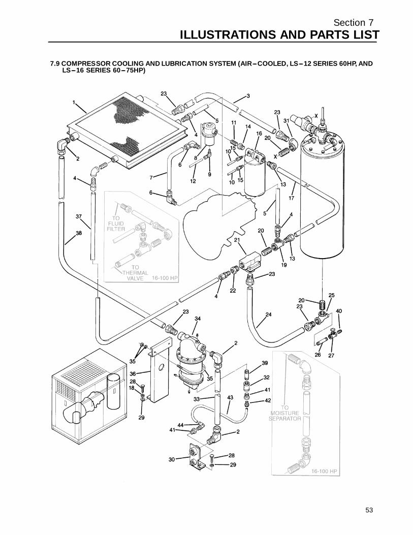
Section 7ILLUSTRATIONS AND PARTS LIST
53
7.9 COMPRESSOR COOLING AND LUBRICATION SYSTEM (AIR---COOLED, LS---12 SERIES 60HP, ANDLS---16 SERIES 60---75HP)
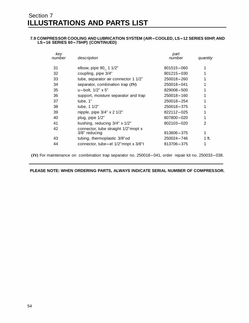
Section 7ILLUSTRATIONS AND PARTS LIST
7.9 COMPRESSOR COOLING AND LUBRICATION SYSTEM (AIR---COOLED, LS---12 SERIES 60HP, ANDLS---16 SERIES 60---75HP) (CONTINUED)
key partnumber description number quantity
31 elbow, pipe 90_ 1 1/2” 801515---060 132 coupling, pipe 3/4” 801215---030 133 tube, separator air connector 1 1/2” 250018---260 134 separator, combination trap (IV) 250018---041 135 u---bolt, 1/2” x 5” 829008---500 136 support, moisture separator and trap 250018---160 137 tube, 1” 250018---254 138 tube, 1 1/2” 250018---375 139 nipple, pipe 3/4” x 2 1/2” 822112---025 140 plug, pipe 1/2” 807800---020 141 bushing, reducing 3/4” x 1/2” 802103---020 242 connector, tube straight 1/2”mnpt x
3/8” reducing 813606---375 143 tubing, thermoplastic 3/8”od 250024---746 1 ft.44 connector, tube---el 1/2”mnpt x 3/8”t 813706---375 1
(IV) For maintenance on combination trap separator no. 250018---041, order repair kit no. 250033---038.
PLEASE NOTE: WHEN ORDERING PARTS, ALWAYS INDICATE SERIAL NUMBER OF COMPRESSOR.
54
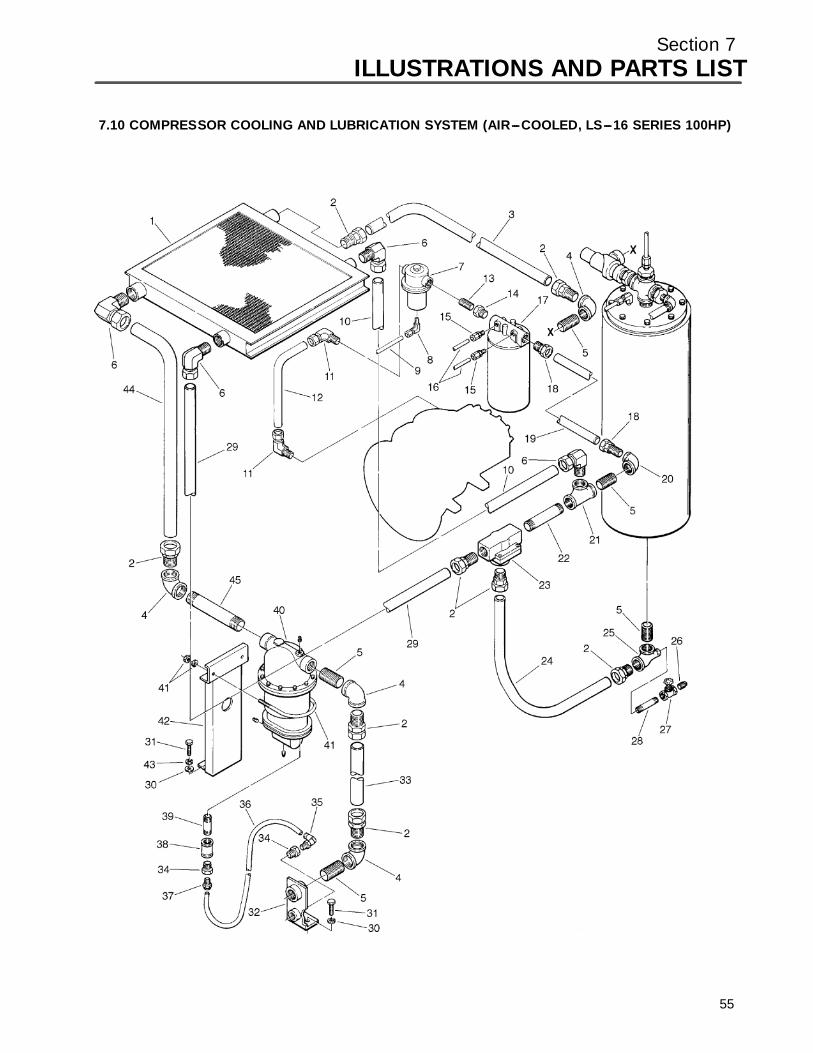
Section 7ILLUSTRATIONS AND PARTS LIST
7.10 COMPRESSOR COOLING AND LUBRICATION SYSTEM (AIR---COOLED, LS---16 SERIES 100HP)
55

Section 7ILLUSTRATIONS AND PARTS LIST
7.10 COMPRESSOR COOLING AND LUBRICATION SYSTEM (AIR---COOLED, LS---16 SERIES 100HP)
key partnumber description number quantity
1 cooler, fluid and aftercooler assembly 250038---658 12 connector, tume---m 1 1/2” x 1 1/2” 810224---150 83 tube, 1 1/2” 250018---259 14 elbow, pipe 90˚ 1 1/2” 801515---060 15 nipple, pipe 1 1/2” x close 822224---000 56 elbow, tube---m 1 1/2” x 1 1/2” 811615---150 47 valve, fluid stop (I) 016741 18 elbow, tube---m 5/16” x 1/4” 810505---025 19 tubing, 5/16” stainless steel 841215---005 2.7 ft.
10 tubing, 1 1/2” 02250060---824 111 elbow, tube---m 1” x 1” 810516---100 312 tube, 1” 250032---112 113 nipple, pipe 1” x close 822216---000 314 bushing, reducing hex 1 1/4” x 1” 802105---040 115 connector, tube---m 1/4” 810204---025 216 tubing, 1/4” 841015---004 10 ft.17 filter, fluid (II) 250025---522 118 connector, tube---m 1 1/4” x 1 1/4” 810220---125 219 tuibe, 1 1/4” 02250045---595 120 elbow, pipe 90˚ 1 1/2” x 1 1/4” 801606---050 121 tee, pipe 1/2” 802415---060 122 nipple, pipe 1 1/2” x 8 1/2” 822124---085 123 valve, thermal (III) 014512 124 tube, 1 1/2” 250018---376 125 tee, reducing 1 1/2” x 1/2” x 1 1/2” 802206---026 126 pipe, plug 1/2” 807800---020 127 valve, globe 1/2” 041007 128 pipe, nipple 1 /2” x 4” 822108---040 129 tube, 1 1/2” 02250060---826 130 washer, reg unfinished 1/2” 837208---112 2
(Continued on page 59)
(I) For maintenance on fluid stop valve no. 016741, order repair kit no. 001684.
(II) For maintenance on fluid filter no. 250025---522, order repair kit no. 250025---526.
(III) For maintenance on thermal valve no. 014512, order repair kit no. 001168.
PLEASE NOTE: WHEN ORDERING PARTS, ALWAYS INDICATE SERIAL NUMBER OF COMPRESSOR.
56

Section 7ILLUSTRATIONS AND PARTS LIST
57
7.10 COMPRESSOR COOLING AND LUBRICATION SYSTEM (AIR---COOLED, LS---16 SERIES 100HP)
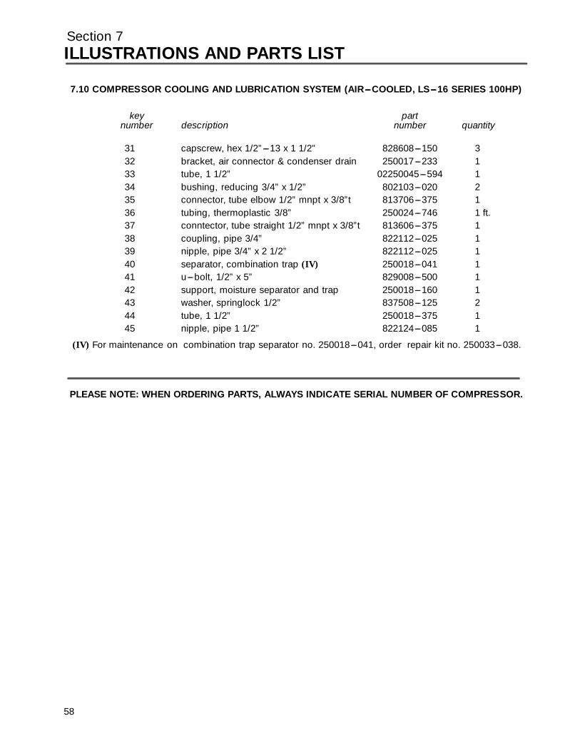
Section 7ILLUSTRATIONS AND PARTS LIST
7.10 COMPRESSOR COOLING AND LUBRICATION SYSTEM (AIR---COOLED, LS---16 SERIES 100HP)
key partnumber description number quantity
31 capscrew, hex 1/2”---13 x 1 1/2” 828608---150 332 bracket, air connector & condenser drain 250017---233 133 tube, 1 1/2” 02250045---594 134 bushing, reducing 3/4” x 1/2” 802103---020 235 connector, tube elbow 1/2” mnpt x 3/8”t 813706---375 136 tubing, thermoplastic 3/8” 250024---746 1 ft.37 conntector, tube straight 1/2” mnpt x 3/8”t 813606---375 138 coupling, pipe 3/4” 822112---025 139 nipple, pipe 3/4” x 2 1/2” 822112---025 140 separator, combination trap (IV) 250018---041 141 u---bolt, 1/2” x 5” 829008---500 142 support, moisture separator and trap 250018---160 143 washer, springlock 1/2” 837508---125 244 tube, 1 1/2” 250018---375 145 nipple, pipe 1 1/2” 822124---085 1
(IV) For maintenance on combination trap separator no. 250018---041, order repair kit no. 250033---038.
PLEASE NOTE: WHEN ORDERING PARTS, ALWAYS INDICATE SERIAL NUMBER OF COMPRESSOR.
58
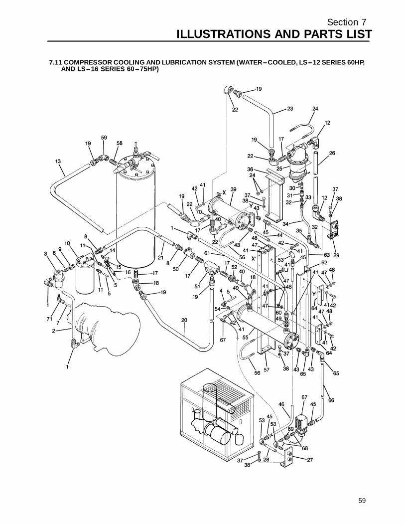
Section 7ILLUSTRATIONS AND PARTS LIST
7.11 COMPRESSOR COOLING AND LUBRICATION SYSTEM (WATER---COOLED, LS---12 SERIES 60HP,AND LS---16 SERIES 60---75HP)
59
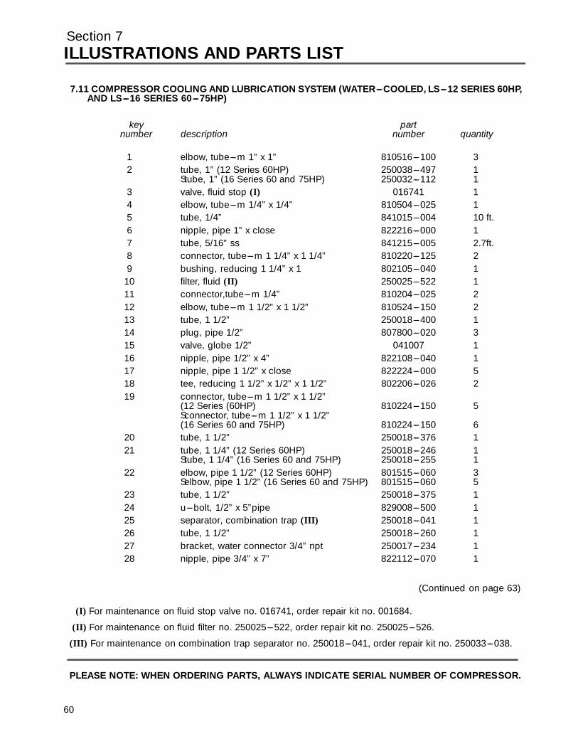
Section 7ILLUSTRATIONS AND PARTS LIST
7.11 COMPRESSOR COOLING AND LUBRICATION SYSTEM (WATER---COOLED, LS---12 SERIES 60HP,AND LS---16 SERIES 60---75HP)
key partnumber description number quantity
1 elbow, tube---m 1” x 1” 810516---100 32 tube, 1” (12 Series 60HP) 250038---497 1
Stube, 1” (16 Series 60 and 75HP) 250032---112 13 valve, fluid stop (I) 016741 14 elbow, tube---m 1/4” x 1/4” 810504---025 15 tube, 1/4” 841015---004 10 ft.6 nipple, pipe 1” x close 822216---000 17 tube, 5/16” ss 841215---005 2.7ft.8 connector, tube---m 1 1/4” x 1 1/4” 810220---125 29 bushing, reducing 1 1/4” x 1 802105---040 1
10 filter, fluid (II) 250025---522 111 connector,tube---m 1/4” 810204---025 212 elbow, tube---m 1 1/2” x 1 1/2” 810524---150 213 tube, 1 1/2” 250018---400 114 plug, pipe 1/2” 807800---020 315 valve, globe 1/2” 041007 116 nipple, pipe 1/2” x 4” 822108---040 117 nipple, pipe 1 1/2” x close 822224---000 518 tee, reducing 1 1/2” x 1/2” x 1 1/2” 802206---026 219 connector, tube---m 1 1/2” x 1 1/2”
(12 Series (60HP) 810224---150 5Sconnector, tube---m 1 1/2” x 1 1/2”(16 Series 60 and 75HP) 810224---150 6
20 tube, 1 1/2” 250018---376 121 tube, 1 1/4” (12 Series 60HP) 250018---246 1
Stube, 1 1/4” (16 Series 60 and 75HP) 250018---255 122 elbow, pipe 1 1/2” (12 Series 60HP) 801515---060 3
Selbow, pipe 1 1/2” (16 Series 60 and 75HP) 801515---060 523 tube, 1 1/2” 250018---375 124 u---bolt, 1/2” x 5”pipe 829008---500 125 separator, combination trap (III) 250018---041 126 tube, 1 1/2” 250018---260 127 bracket, water connector 3/4” npt 250017---234 128 nipple, pipe 3/4” x 7” 822112---070 1
(Continued on page 63)
(I) For maintenance on fluid stop valve no. 016741, order repair kit no. 001684.
(II) For maintenance on fluid filter no. 250025---522, order repair kit no. 250025---526.
(III) For maintenance on combination trap separator no. 250018---041, order repair kit no. 250033---038.
PLEASE NOTE: WHEN ORDERING PARTS, ALWAYS INDICATE SERIAL NUMBER OF COMPRESSOR.
60

Section 7ILLUSTRATIONS AND PARTS LIST
61
7.11 COMPRESSOR COOLING AND LUBRICATION SYSTEM (WATER---COOLED, LS---12 SERIES 60HP,AND LS---16 SERIES 60---75HP)
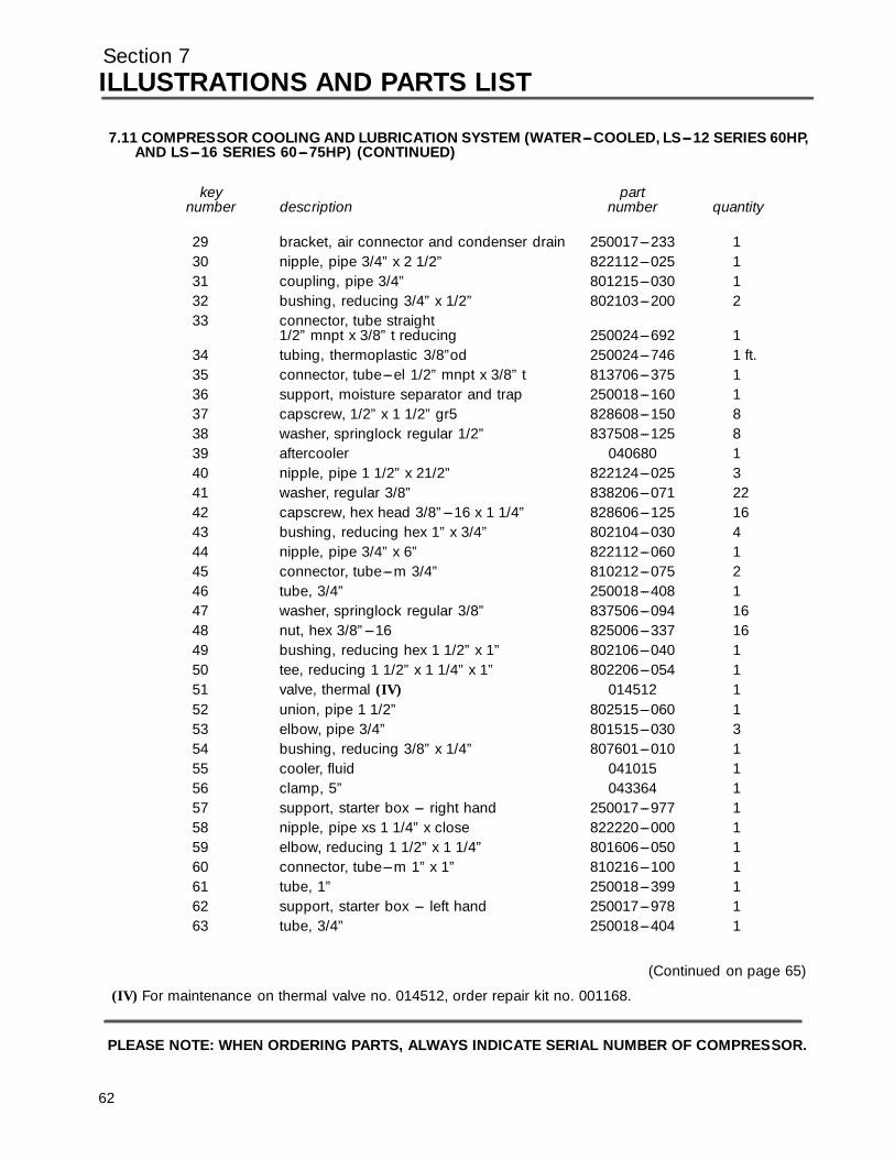
Section 7ILLUSTRATIONS AND PARTS LIST
7.11 COMPRESSOR COOLING AND LUBRICATION SYSTEM (WATER---COOLED, LS---12 SERIES 60HP,AND LS---16 SERIES 60---75HP) (CONTINUED)
key partnumber description number quantity
29 bracket, air connector and condenser drain 250017---233 130 nipple, pipe 3/4” x 2 1/2” 822112---025 131 coupling, pipe 3/4” 801215---030 132 bushing, reducing 3/4” x 1/2” 802103---200 233 connector, tube straight
1/2” mnpt x 3/8” t reducing 250024---692 134 tubing, thermoplastic 3/8”od 250024---746 1 ft.35 connector, tube---el 1/2” mnpt x 3/8” t 813706---375 136 support, moisture separator and trap 250018---160 137 capscrew, 1/2” x 1 1/2” gr5 828608---150 838 washer, springlock regular 1/2” 837508---125 839 aftercooler 040680 140 nipple, pipe 1 1/2” x 21/2” 822124---025 341 washer, regular 3/8” 838206---071 2242 capscrew, hex head 3/8”---16 x 1 1/4” 828606---125 1643 bushing, reducing hex 1” x 3/4” 802104---030 444 nipple, pipe 3/4” x 6” 822112---060 145 connector, tube---m 3/4” 810212---075 246 tube, 3/4” 250018---408 147 washer, springlock regular 3/8” 837506---094 1648 nut, hex 3/8”---16 825006---337 1649 bushing, reducing hex 1 1/2” x 1” 802106---040 150 tee, reducing 1 1/2” x 1 1/4” x 1” 802206---054 151 valve, thermal (IV) 014512 152 union, pipe 1 1/2” 802515---060 153 elbow, pipe 3/4” 801515---030 354 bushing, reducing 3/8” x 1/4” 807601---010 155 cooler, fluid 041015 156 clamp, 5” 043364 157 support, starter box --- right hand 250017---977 158 nipple, pipe xs 1 1/4” x close 822220---000 159 elbow, reducing 1 1/2” x 1 1/4” 801606---050 160 connector, tube---m 1” x 1” 810216---100 161 tube, 1” 250018---399 162 support, starter box --- left hand 250017---978 163 tube, 3/4” 250018---404 1
(Continued on page 65)
(IV) For maintenance on thermal valve no. 014512, order repair kit no. 001168.
PLEASE NOTE: WHEN ORDERING PARTS, ALWAYS INDICATE SERIAL NUMBER OF COMPRESSOR.
62

Section 7ILLUSTRATIONS AND PARTS LIST
63
7.11 COMPRESSOR COOLING AND LUBRICATION SYSTEM (WATER---COOLED, LS---12 SERIES 60HP,AND LS---16 SERIES 60---75HP)
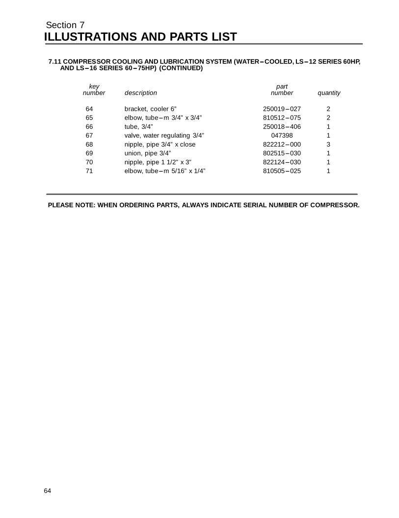
Section 7ILLUSTRATIONS AND PARTS LIST
6
7.11 COMPRESSOR COOLING AND LUBRICATION SYSTEM (WATER---COOLED, LS---12 SERIES 60HP,AND LS---16 SERIES 60---75HP) (CONTINUED)
key partnumber description number quantity
64 bracket, cooler 6” 250019---027 265 elbow, tube---m 3/4” x 3/4” 810512---075 266 tube, 3/4” 250018---406 167 valve, water regulating 3/4” 047398 168 nipple, pipe 3/4” x close 822212---000 369 union, pipe 3/4” 802515---030 170 nipple, pipe 1 1/2” x 3” 822124---030 171 elbow, tube---m 5/16” x 1/4” 810505---025 1
PLEASE NOTE: WHEN ORDERING PARTS, ALWAYS INDICATE SERIAL NUMBER OF COMPRESSOR.
4

Section 7ILLUSTRATIONS AND PARTS LIST
7.12 COMPRESSOR COOLING AND LUBRICATION SYSTEM (WATER---COOLED, LS---16 SERIES100HP)
65
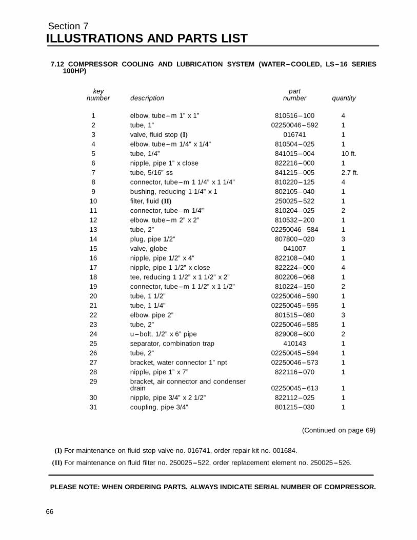
Section 7ILLUSTRATIONS AND PARTS LIST
7.12 COMPRESSOR COOLING AND LUBRICATION SYSTEM (WATER---COOLED, LS---16 SERIES100HP)
key partnumber description number quantity
1 elbow, tube---m 1” x 1” 810516---100 42 tube, 1” 02250046---592 13 valve, fluid stop (I) 016741 14 elbow, tube---m 1/4” x 1/4” 810504---025 15 tube, 1/4” 841015---004 10 ft.6 nipple, pipe 1” x close 822216---000 17 tube, 5/16” ss 841215---005 2.7 ft.8 connector, tube---m 1 1/4” x 1 1/4” 810220---125 49 bushing, reducing 1 1/4” x 1 802105---040 1
10 filter, fluid (II) 250025---522 111 connector, tube---m 1/4” 810204---025 212 elbow, tube---m 2” x 2” 810532---200 113 tube, 2” 02250046---584 114 plug, pipe 1/2” 807800---020 315 valve, globe 041007 116 nipple, pipe 1/2” x 4” 822108---040 117 nipple, pipe 1 1/2” x close 822224---000 418 tee, reducing 1 1/2” x 1 1/2” x 2” 802206---068 119 connector, tube---m 1 1/2” x 1 1/2” 810224---150 220 tube, 1 1/2” 02250046---590 121 tube, 1 1/4” 02250045---595 122 elbow, pipe 2” 801515---080 323 tube, 2” 02250046---585 124 u---bolt, 1/2” x 6” pipe 829008---600 225 separator, combination trap 410143 126 tube, 2” 02250045---594 127 bracket, water connector 1” npt 02250046---573 128 nipple, pipe 1” x 7” 822116---070 129 bracket, air connector and condenser
drain 02250045---613 130 nipple, pipe 3/4” x 2 1/2” 822112---025 131 coupling, pipe 3/4” 801215---030 1
(Continued on page 69)
(I) For maintenance on fluid stop valve no. 016741, order repair kit no. 001684.
(II) For maintenance on fluid filter no. 250025---522, order replacement element no. 250025---526.
PLEASE NOTE: WHEN ORDERING PARTS, ALWAYS INDICATE SERIAL NUMBER OF COMPRESSOR.
66
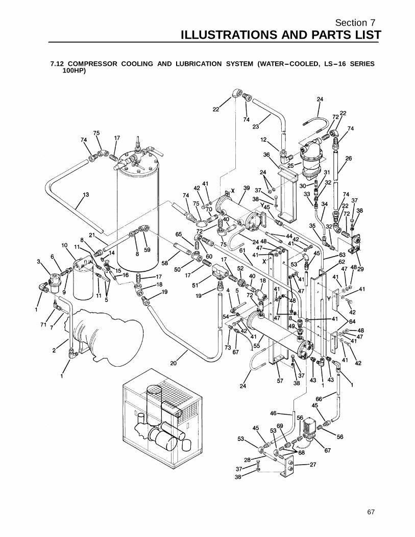
Section 7ILLUSTRATIONS AND PARTS LIST
67
7.12 COMPRESSOR COOLING AND LUBRICATION SYSTEM (WATER---COOLED, LS---16 SERIES100HP)
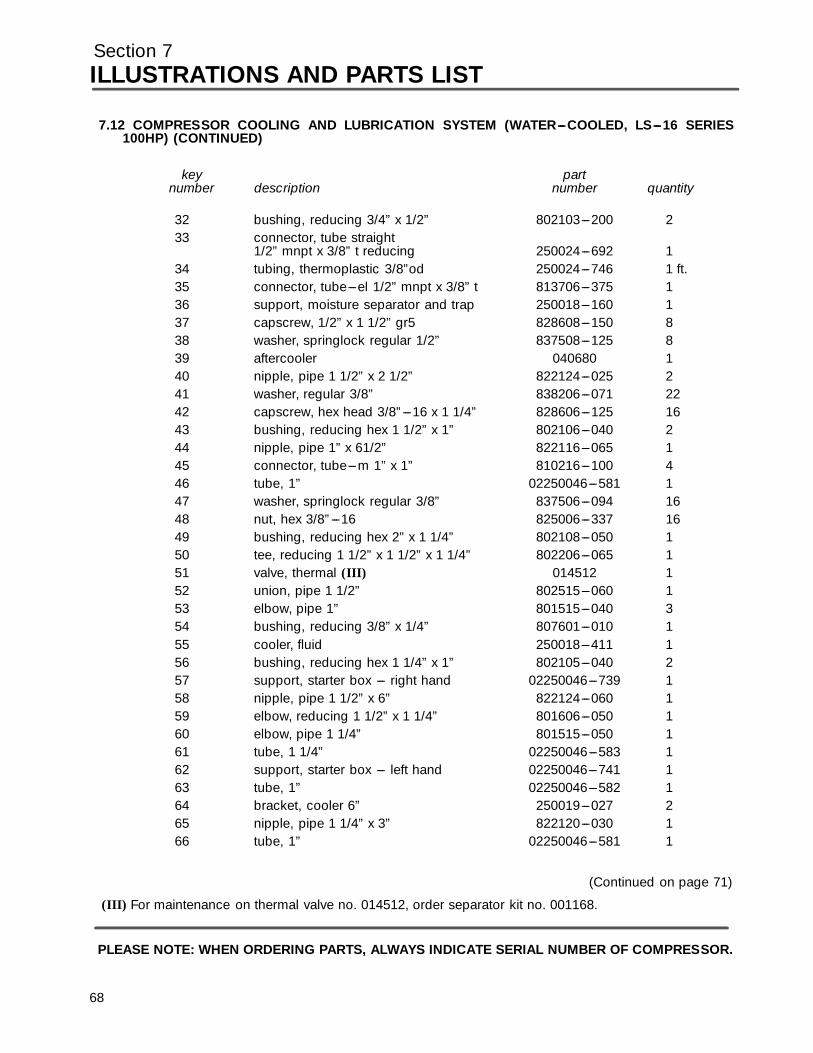
Section 7ILLUSTRATIONS AND PARTS LIST
7.12 COMPRESSOR COOLING AND LUBRICATION SYSTEM (WATER---COOLED, LS---16 SERIES100HP) (CONTINUED)
key partnumber description number quantity
32 bushing, reducing 3/4” x 1/2” 802103---200 233 connector, tube straight
1/2” mnpt x 3/8” t reducing 250024---692 134 tubing, thermoplastic 3/8”od 250024---746 1 ft.35 connector, tube---el 1/2” mnpt x 3/8” t 813706---375 136 support, moisture separator and trap 250018---160 137 capscrew, 1/2” x 1 1/2” gr5 828608---150 838 washer, springlock regular 1/2” 837508---125 839 aftercooler 040680 140 nipple, pipe 1 1/2” x 2 1/2” 822124---025 241 washer, regular 3/8” 838206---071 2242 capscrew, hex head 3/8”---16 x 1 1/4” 828606---125 1643 bushing, reducing hex 1 1/2” x 1” 802106---040 244 nipple, pipe 1” x 61/2” 822116---065 145 connector, tube---m 1” x 1” 810216---100 446 tube, 1” 02250046---581 147 washer, springlock regular 3/8” 837506---094 1648 nut, hex 3/8”---16 825006---337 1649 bushing, reducing hex 2” x 1 1/4” 802108---050 150 tee, reducing 1 1/2” x 1 1/2” x 1 1/4” 802206---065 151 valve, thermal (III) 014512 152 union, pipe 1 1/2” 802515---060 153 elbow, pipe 1” 801515---040 354 bushing, reducing 3/8” x 1/4” 807601---010 155 cooler, fluid 250018---411 156 bushing, reducing hex 1 1/4” x 1” 802105---040 257 support, starter box --- right hand 02250046---739 158 nipple, pipe 1 1/2” x 6” 822124---060 159 elbow, reducing 1 1/2” x 1 1/4” 801606---050 160 elbow, pipe 1 1/4” 801515---050 161 tube, 1 1/4” 02250046---583 162 support, starter box --- left hand 02250046---741 163 tube, 1” 02250046---582 164 bracket, cooler 6” 250019---027 265 nipple, pipe 1 1/4” x 3” 822120---030 166 tube, 1” 02250046---581 1
(Continued on page 71)
(III) For maintenance on thermal valve no. 014512, order separator kit no. 001168.
PLEASE NOTE: WHEN ORDERING PARTS, ALWAYS INDICATE SERIAL NUMBER OF COMPRESSOR.
68

Section 7ILLUSTRATIONS AND PARTS LIST
69
7.12 COMPRESSOR COOLING AND LUBRICATION SYSTEM (WATER---COOLED, LS---16 SERIES100HP)
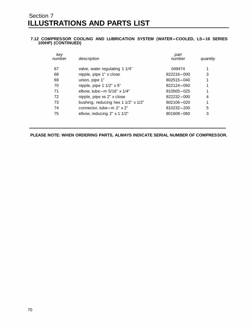
Section 7ILLUSTRATIONS AND PARTS LIST
7.12 COMPRESSOR COOLING AND LUBRICATION SYSTEM (WATER---COOLED, LS---16 SERIES100HP) (CONTINUED)
key partnumber description number quantity
67 valve, water regulating 1 1/4” 049474 168 nipple, pipe 1” x close 822216---000 369 union, pipe 1” 802515---040 170 nipple, pipe 1 1/2” x 5” 822124---050 171 elbow, tube---m 5/16” x 1/4” 810505---025 172 nipple, pipe xs 2” x close 822232---000 473 bushing, reducing hex 1 1/2” x 1/2” 802106---020 174 connector, tube---m 2” x 2” 810232---200 575 elbow, reducing 2” x 1 1/2” 801608---060 3
PLEASE NOTE: WHEN ORDERING PARTS, ALWAYS INDICATE SERIAL NUMBER OF COMPRESSOR.
70
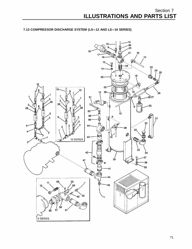
Section 7ILLUSTRATIONS AND PARTS LIST
7.13 COMPRESSOR DISCHARGE SYSTEM (LS---12 AND LS---16 SERIES)
71
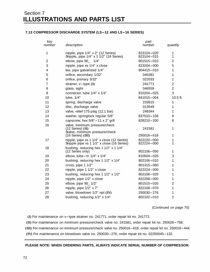
Section 7ILLUSTRATIONS AND PARTS LIST
7.13 COMPRESSOR DISCHARGE SYSTEM (LS---12 AND LS---16 SERIES)
key partnumber description number quantity
1 nipple, pipe 1/4” x 2” (12 Series) 823104---020 1Snipple, pipe 1/4” x 1 1/2” (16 Series) 823104---015 1
2 elbow, pipe 90_ 1/4” 801515---010 23 nipple, pipe xs 1/4” x close 823204---000 54 tee, pipe galvanized 1/4” 804415---010 15 orifice, secondary 1/32” 040381 16 orifice, primary 3/32” 022033 17 strainer, v--- type (I) 241771 28 glass, sight 046559 29 connector, tube 1/4” x 1/4” 810204---025 3
10 tube, 1/4” 841015---004 10.5 ft.11 spring, discharge valve 233615 112 disc, discharge valve 013549 113 valve, relief 175 psig (12.1 bar) 248344 114 washer, springlock regular 5/8” 837510---156 815 capscrew, hex 5/8”---11 x 2” gr8 828210---200 816 valve, minimum pressure/check
(12 Series) (II) 241581 1Svalve, minimum pressure/check(16 Series) (III) 250016---618 1
17 nipple, pipe xs 1 1/4” x close (12 Series) 822220---000 1Snipple pipe xs 1 1/2” x close (16 Series) 822224---000 1
18 bushing, reducing hex 1 1/2” x 1 1/4”(12 Series only) 802106---050 1
19 elbow, tube---m 1/4” x 1/4” 810504---025 320 bushing, reducing hex 1 1/2” x 1/4” 802106---010 121 cross, pipe 1 1/2” 801315---060 122 nipple, pipe 1 1/2” x close 822224---000 123 bushing, reducing hex 1 1/2” x 1/2” 802106---020 124 nipple, pipe 1/2” x close 822208---000 125 elbow, pipe 90_ 1/2” 801515---020 226 nipple, pipe 1/2” x 7” 822108---070 127 valve, blowdown 1/2” npt (IV) 250030---276 128 bushing, reducing 1/2” x 1/4” 802102---010 2
(Continued on page 75)
(I) For maintenance on v--- type strainer no. 241771, order repair kit no. 241772.
(II) For maintenance on minimum pressure/check valve no. 241581, order repair kit no. 250026---758.
(III) For maintenance on minimum pressure/check valve no. 250016---618, order repair kit no. 250019---444.
(IV) For maintenance on blowdown valve no. 250030---276, order repair kit no. 02250045---132.
PLEASE NOTE: WHEN ORDERING PARTS, ALWAYS INDICATE SERIAL NUMBER OF COMPRESSOR.
72

Section 7ILLUSTRATIONS AND PARTS LIST
73
7.13 COMPRESSOR DISCHARGE SYSTEM (LS---12 AND LS---16 SERIES)
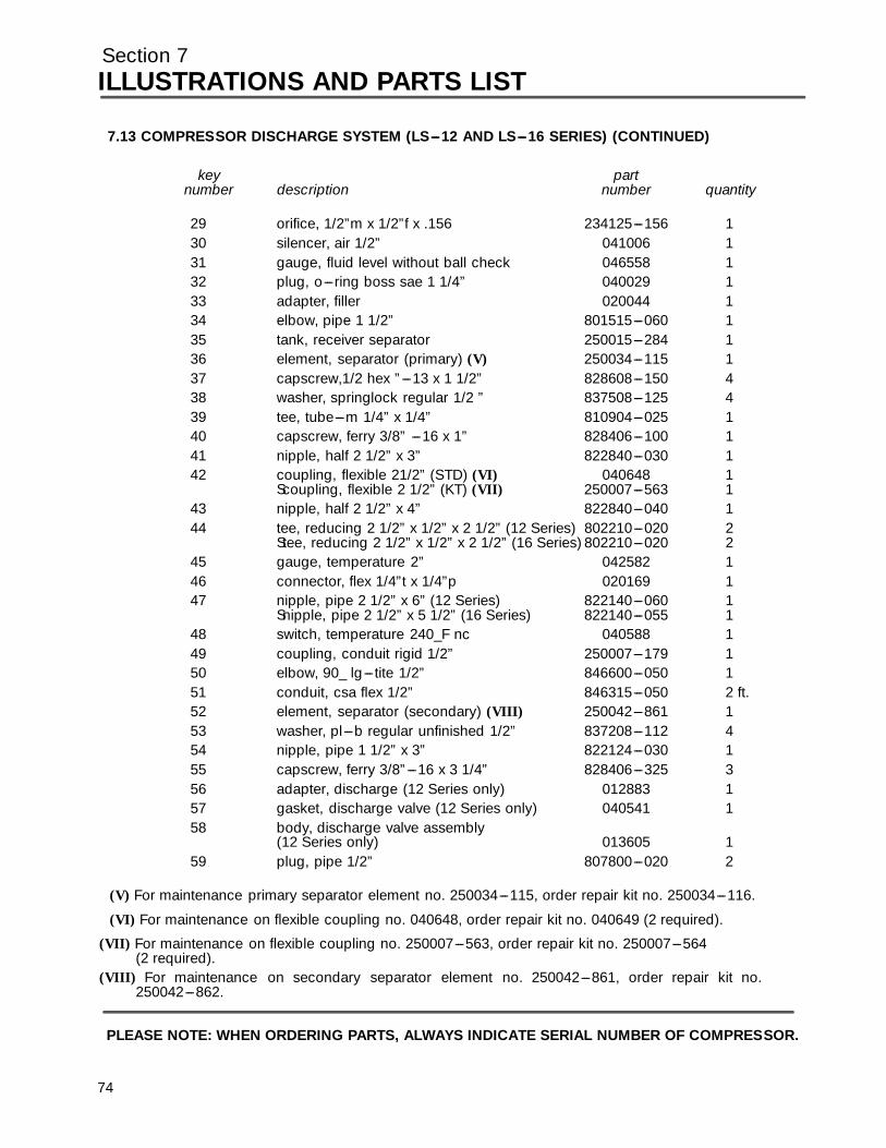
Section 7ILLUSTRATIONS AND PARTS LIST
7.13 COMPRESSOR DISCHARGE SYSTEM (LS---12 AND LS---16 SERIES) (CONTINUED)
key partnumber description number quantity
29 orifice, 1/2”m x 1/2”f x .156 234125---156 130 silencer, air 1/2” 041006 131 gauge, fluid level without ball check 046558 132 plug, o---ring boss sae 1 1/4” 040029 133 adapter, filler 020044 134 elbow, pipe 1 1/2” 801515---060 135 tank, receiver separator 250015---284 136 element, separator (primary) (V) 250034---115 137 capscrew,1/2 hex ”---13 x 1 1/2” 828608---150 438 washer, springlock regular 1/2 ” 837508---125 439 tee, tube---m 1/4” x 1/4” 810904---025 140 capscrew, ferry 3/8” ---16 x 1” 828406---100 141 nipple, half 2 1/2” x 3” 822840---030 142 coupling, flexible 21/2” (STD) (VI) 040648 1
Scoupling, flexible 2 1/2” (KT) (VII) 250007---563 143 nipple, half 2 1/2” x 4” 822840---040 144 tee, reducing 2 1/2” x 1/2” x 2 1/2” (12 Series) 802210---020 2
Stee, reducing 2 1/2” x 1/2” x 2 1/2” (16 Series) 802210---020 245 gauge, temperature 2” 042582 146 connector, flex 1/4”t x 1/4”p 020169 147 nipple, pipe 2 1/2” x 6” (12 Series) 822140---060 1
Snipple, pipe 2 1/2” x 5 1/2” (16 Series) 822140---055 148 switch, temperature 240_F nc 040588 149 coupling, conduit rigid 1/2” 250007---179 150 elbow, 90_ lg--- tite 1/2” 846600---050 151 conduit, csa flex 1/2” 846315---050 2 ft.52 element, separator (secondary) (VIII) 250042---861 153 washer, pl---b regular unfinished 1/2” 837208---112 454 nipple, pipe 1 1/2” x 3” 822124---030 155 capscrew, ferry 3/8”---16 x 3 1/4” 828406---325 356 adapter, discharge (12 Series only) 012883 157 gasket, discharge valve (12 Series only) 040541 158 body, discharge valve assembly
(12 Series only) 013605 159 plug, pipe 1/2” 807800---020 2
(V) For maintenance primary separator element no. 250034---115, order repair kit no. 250034---116.
(VI) For maintenance on flexible coupling no. 040648, order repair kit no. 040649 (2 required).
(VII) For maintenance on flexible coupling no. 250007---563, order repair kit no. 250007---564(2 required).
(VIII) For maintenance on secondary separator element no. 250042---861, order repair kit no.250042---862.
PLEASE NOTE: WHEN ORDERING PARTS, ALWAYS INDICATE SERIAL NUMBER OF COMPRESSOR.
74
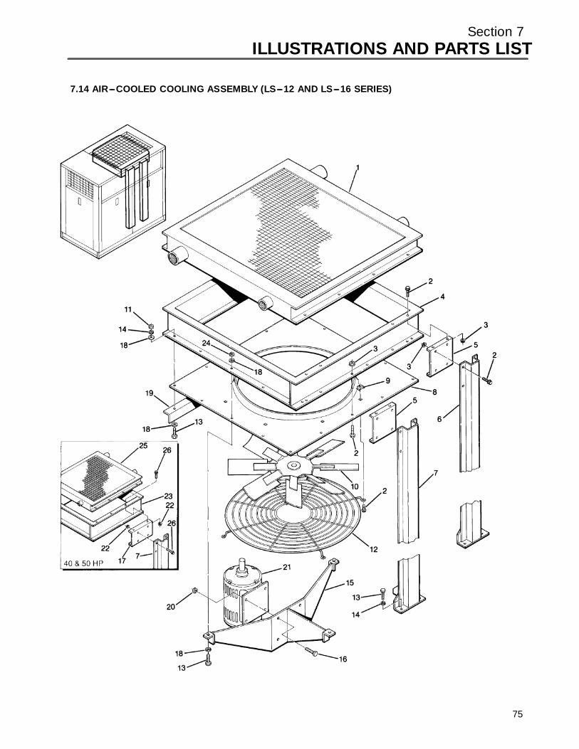
Section 7ILLUSTRATIONS AND PARTS LIST
7.14 AIR---COOLED COOLING ASSEMBLY (LS---12 AND LS---16 SERIES)
75

Section 7ILLUSTRATIONS AND PARTS LIST
7.14 AIR---COOLED COOLING ASSEMBLY (LS---12 AND LS---16 SERIES)
key partnumber description number quantity
1 cooler, fluid aftercooler assemblyS12 Series 40HP 250038---657 1S12 Series 50 and 60HP; 16 Series 60 and 75 HP 250038---658 1S16 Series 100HP 02250053---915 1
2 screw, hex serrated washerS12 Series 60HP 829705---075 39!16 Series 60, 75 and 100HP 829705---075 43
3 nut, hex flanged plated washer 5/16”---18!12 Series 60HP 825305---283 37!16 Series 60, 75 and 100HP 825305---283 41
4 adapter, venturi!12 Series 40 and 50HP 250017---271 1!12 Series 60HP; 16 Series 60 and 75 HP 250017---270 1!16 Series 100HP 02250043---113 1
5 bracket, cooler support!12 Series 60HP; 16 Series 60 and 75 HP 250018---002 2!16 Series 100HP 02250043---127 2
6 support, cooler 54 1/4” 250017---631 17 support, cooler 54 1/4”
12 Series 60HP; 16 Series 60, 75 and 100HP 250017---630 18 panel, venturi
!12 Series 40 and 50HP 250017---494 1!12 Series 60HP; 16 Series 60, 75 and 100HP 250017---495 1
9 nut, retainer 5/16”---18 861405---092 410 fan, 22”
!12 Series 40 and 50HP 241390 1!12 Series 60HP; 16 Series 60, 75 and 100HP 049971 1
11 nut hex 3/8”---16 824206---337 812 guard, fan 24”
!12 Series 40 and 50HP 241501 1!12 Series 60HP; 16 Series 60, 75 and 100HP 241079 1
13 capscrew, hex 3/8” x 1 1/4” gr5!12 Series 40 and 50HP 828606---125 7!12 Series 60HP; 16 Series 60, 75and 100HP 828606---125 9
(Continued on page 79)
PLEASE NOTE: WHEN ORDERING PARTS, ALWAYS INDICATE SERIAL NUMBER OF COMPRESSOR.
76

Section 7ILLUSTRATIONS AND PARTS LIST
77
7.14 AIR---COOLED COOLING ASSEMBLY (LS---12 AND LS---16 SERIES)

Section 7ILLUSTRATIONS AND PARTS LIST
7
7.14 AIR---COOLED COOLING ASSEMBLY (LS---12 AND LS---16 SERIES) (CONTINUED)
key partnumber description number quantity
14 washer, springlock regular 3/8”!12 Series 40 and 50HP 837506---094 11!12 Series 60HP; 16 Series 60, 75 and 100HP 837506---094 13
15 support, fan motor!12 Series 40 and 50HP 250017---499 1!12 Series 60HP; 16 Series 60, 75 and 100HP 250017---502 1
16 capscrew, hex 5/16”---18 x 1” gr5!12 Series 40 and 50HP 828605---100 7!12 Series 60HP; 16 Series 60, 75 and 100HP 828606---100 3
17 bracket, cooler support12 Series 40 and 50HP 250018---114 1
18 washer, pl---b regular 3/8”!12 Series 40 and 50HP 838206---071 11!12 Series 60HP; 16 Series 60, and 75HP 838206---071 16!16 Series 100HP 838206---071 23
19 angle, cooler support!12 Series 40 and 50HP 250018---121 1!12 Series 60HP; 16 Series 60, 75and 100HP 250017---996 1
20 nut, hex locking plated 5/16”---18 825505---166 421 motor, 2HP
12 Series 40 and 50HP 041034 1!motor, 3HP12 Series 60HP; 16 Series 60, 75 and 100HP 041035 1
22 nut, hex flanged plated 5/16”---1812 Series 40 and 50HP 825305---283 29
23 adapter, venturi12 Series 40 and 50HP 250017---271 1
24 nut, hex locking plated 3/8”---112 Series 60HP; 16 Series 60, 75 and 100HP 825506---198 7
25 cooler, fluid aftercooler assembly12 Series 40 and 50HP 250038---657 1
26 screw, hex serrated washer 5/16” x 3/4”12 Series 40 and 50HP 829705---075 31
PLEASE NOTE: WHEN ORDERING PARTS, ALWAYS INDICATE SERIAL NUMBER OF COMPRESSOR.
8
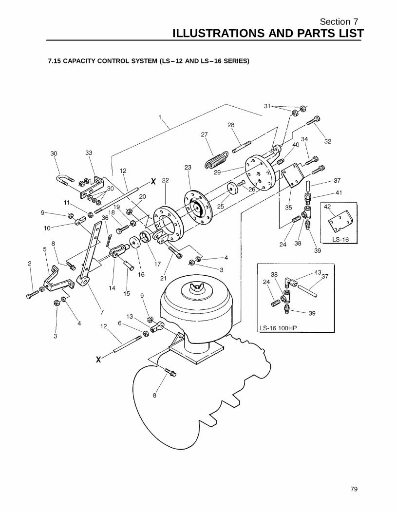
Section 7ILLUSTRATIONS AND PARTS LIST
7.15 CAPACITY CONTROL SYSTEM (LS---12 AND LS---16 SERIES)
79
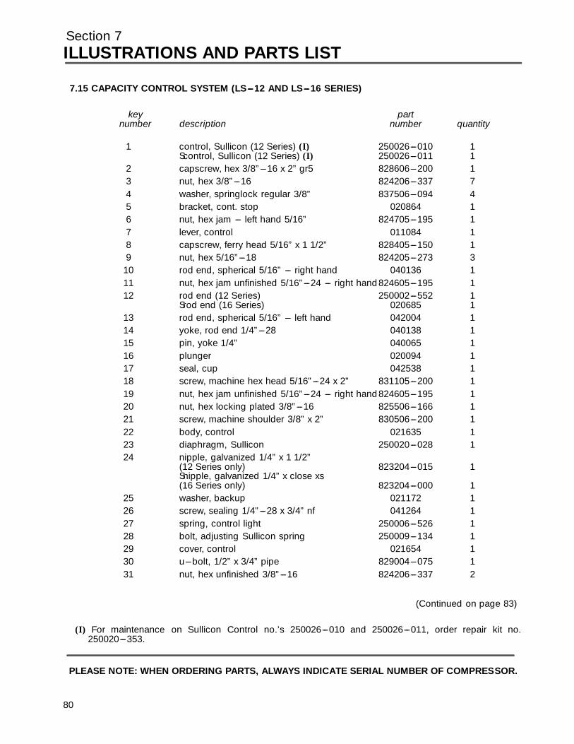
Section 7ILLUSTRATIONS AND PARTS LIST
8
7.15 CAPACITY CONTROL SYSTEM (LS---12 AND LS---16 SERIES)
key partnumber description number quantity
1 control, Sullicon (12 Series) (I) 250026---010 1Scontrol, Sullicon (12 Series) (I) 250026---011 1
2 capscrew, hex 3/8”---16 x 2” gr5 828606---200 13 nut, hex 3/8”---16 824206---337 74 washer, springlock regular 3/8” 837506---094 45 bracket, cont. stop 020864 16 nut, hex jam --- left hand 5/16” 824705---195 17 lever, control 011084 18 capscrew, ferry head 5/16” x 1 1/2” 828405---150 19 nut, hex 5/16”---18 824205---273 3
10 rod end, spherical 5/16” --- right hand 040136 111 nut, hex jam unfinished 5/16”---24 --- right hand824605---195 112 rod end (12 Series) 250002---552 1
Srod end (16 Series) 020685 113 rod end, spherical 5/16” --- left hand 042004 114 yoke, rod end 1/4”---28 040138 115 pin, yoke 1/4” 040065 116 plunger 020094 117 seal, cup 042538 118 screw, machine hex head 5/16”---24 x 2” 831105---200 119 nut, hex jam unfinished 5/16”---24 --- right hand824605---195 120 nut, hex locking plated 3/8”---16 825506---166 121 screw, machine shoulder 3/8” x 2” 830506---200 122 body, control 021635 123 diaphragm, Sullicon 250020---028 124 nipple, galvanized 1/4” x 1 1/2”
(12 Series only) 823204---015 1Snipple, galvanized 1/4” x close xs(16 Series only) 823204---000 1
25 washer, backup 021172 126 screw, sealing 1/4”---28 x 3/4” nf 041264 127 spring, control light 250006---526 128 bolt, adjusting Sullicon spring 250009---134 129 cover, control 021654 130 u---bolt, 1/2” x 3/4” pipe 829004---075 131 nut, hex unfinished 3/8”---16 824206---337 2
(Continued on page 83)
(I) For maintenance on Sullicon Control no.’s 250026---010 and 250026---011, order repair kit no.250020---353.
PLEASE NOTE: WHEN ORDERING PARTS, ALWAYS INDICATE SERIAL NUMBER OF COMPRESSOR.
0

Section 7ILLUSTRATIONS AND PARTS LIST
81
7.15 CAPACITY CONTROL SYSTEM (LS---12 AND LS---16 SERIES)

Section 7ILLUSTRATIONS AND PARTS LIST
7.15 CAPACITY CONTROL SYSTEM (LS---12 AND LS---16 SERIES) (CONTINUED)
key partnumber description number quantity
32 capscrew, hex 5/16”---18 x 2 1/2” gr5 828605---250 233 bracket, (12 Series only) 250039---115 1
Sbracket, (16 Series only) 250039---114 134 capscrew, hex 3/8”---16 x 2 1/2” gr5 828606---250 335 bracket, control (12 Series only) 223681 136 pin, cotter 1/16” x 3/4” 827101---075 137 tubing, 1/4” 841015---004 12 ft.38 tee, pipe galvanized 1/4” 804415---010 139 valve, drain self---close 1/8”npt 041111 140 plug, pipe 1/4” 807800---010 141 connector, tube---m 1/4” x 1/4” (12 Series) 810204---025 142 bracket, control (16 Series only) 234217 143 elbow, tube---m 1/4” x 1/4” (16 Series) 810504---025 1
PLEASE NOTE: WHEN ORDERING PARTS, ALWAYS INDICATE SERIAL NUMBER OF COMPRESSOR.
82

Section 7ILLUSTRATIONS AND PARTS LIST
7.16 INSTRUMENT PANEL AND PARTS (LS---12 AND LS---16 SERIES)
83

Section 7ILLUSTRATIONS AND PARTS LIST
7.16 INSTRUMENT PANEL AND PARTS (LS---12 AND LS---16 SERIES)
key partnumber description number quantity
1 union, tube 1/4” x 1/4” 811104---025 52 screw, tc--- f pan #8---32 x 1/2” 835601---050 43 tubing, 1/4” 841015---004 10 ft.4 connector, tube--- f 1/4” x 1/8” 810104---012 55 tee, tube--- f 1/4” x 1/8” 811004---012 16 connector, tube--- f 1/4” x 1/8” 250025---327 17 angle, instrument panel 02250044---407 18 hose, nylon 1/4” 842215---004 6 ft.9 panel, instrument 250019---481 1
10 decal, instrument panel 02250051---301 111 gauge, differential pressure 0---30 psi
(0---2.1 bar) 250003---799 112 gauge, vacuum 0---30 water 250003---797 113 gauge, differential pressure 0---15 psi
(0---1 bar) 250003---798 114 gauge, pressure 2” diameter 250005---185 215 gauge, temperature 2” 042582 116 switch, pushbutton START 250016---351 117 switch, pushbutton STOP 250016---350 118 panel, electrical 250015---471 119 gasket, hourmeter 410353 120 hourmeter, 60 Hz 250015---715 1
Shourmeter, 50 Hz 250042---010 121 nut, hex washer 1/4” 825304---236 122 decal, electrical panel 02250051---388 123 holder, pilot lamp 043383 1
Slens, green 043385 1Slens, red 043384 1Slens, amber 047016 1Sbulb, pilot lamp 043386 1
24 support, instrument panel 02250044---405 125 screw, hex ser washer 5/16” x 3/4” 829705---075 126 screw, hex ser washer 1/4” x 3/4” 829704---075 127 nut, hex washer 5/16” 825305---283 128 switch, sel 2 pos 250016---352 129 support, inst panel 250038---097 1
PLEASE NOTE: WHEN ORDERING PARTS, ALWAYS INDICATE SERIAL NUMBER OF COMPRESSOR.
84

Section 7ILLUSTRATIONS AND PARTS LIST
7.17 ELECTRO---PNEUMATIC CONTROL SYSTEM (LS---12 AND LS---16 SERIES)
85
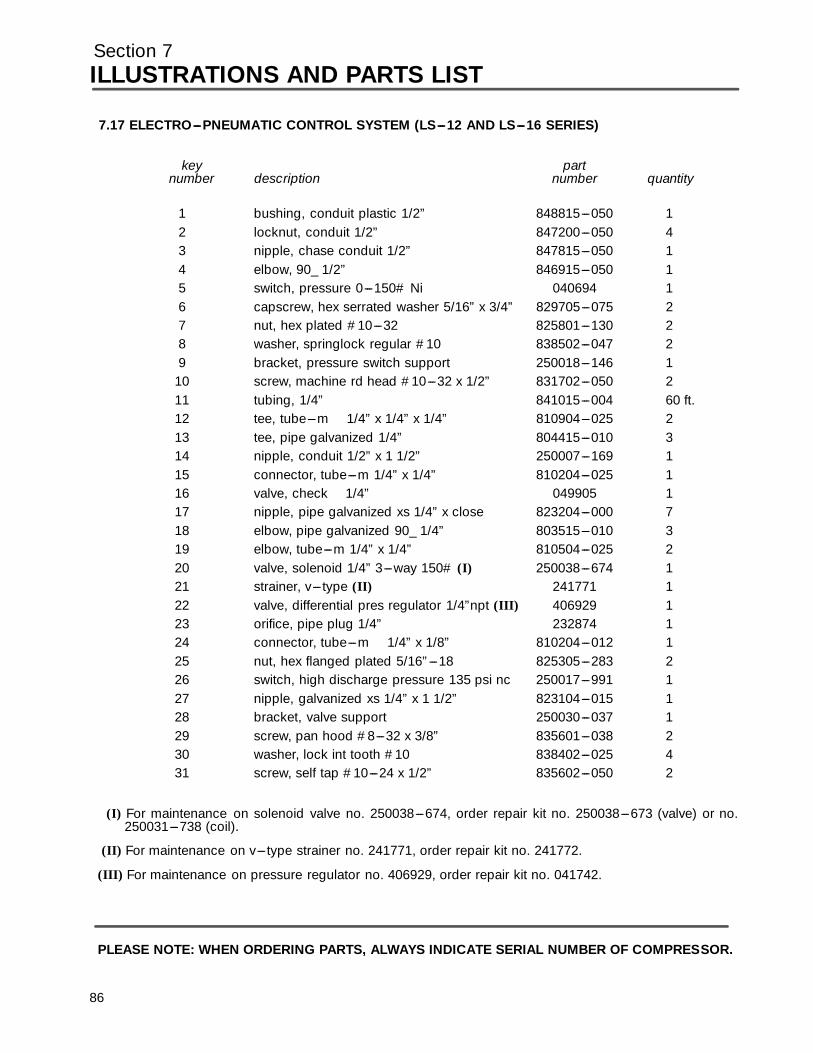
Section 7ILLUSTRATIONS AND PARTS LIST
7.17 ELECTRO---PNEUMATIC CONTROL SYSTEM (LS---12 AND LS---16 SERIES)
key partnumber description number quantity
1 bushing, conduit plastic 1/2” 848815---050 12 locknut, conduit 1/2” 847200---050 43 nipple, chase conduit 1/2” 847815---050 14 elbow, 90_ 1/2” 846915---050 15 switch, pressure 0---150# Ni 040694 16 capscrew, hex serrated washer 5/16” x 3/4” 829705---075 27 nut, hex plated #10---32 825801---130 28 washer, springlock regular #10 838502---047 29 bracket, pressure switch support 250018---146 1
10 screw, machine rd head #10---32 x 1/2” 831702---050 211 tubing, 1/4” 841015---004 60 ft.12 tee, tube---m 1/4” x 1/4” x 1/4” 810904---025 213 tee, pipe galvanized 1/4” 804415---010 314 nipple, conduit 1/2” x 1 1/2” 250007---169 115 connector, tube---m 1/4” x 1/4” 810204---025 116 valve, check 1/4” 049905 117 nipple, pipe galvanized xs 1/4” x close 823204---000 718 elbow, pipe galvanized 90_ 1/4” 803515---010 319 elbow, tube---m 1/4” x 1/4” 810504---025 220 valve, solenoid 1/4” 3---way 150# (I) 250038---674 121 strainer, v--- type (II) 241771 122 valve, differential pres regulator 1/4”npt (III) 406929 123 orifice, pipe plug 1/4” 232874 124 connector, tube---m 1/4” x 1/8” 810204---012 125 nut, hex flanged plated 5/16”---18 825305---283 226 switch, high discharge pressure 135 psi nc 250017---991 127 nipple, galvanized xs 1/4” x 1 1/2” 823104---015 128 bracket, valve support 250030---037 129 screw, pan hood #8---32 x 3/8” 835601---038 230 washer, lock int tooth #10 838402---025 431 screw, self tap #10---24 x 1/2” 835602---050 2
(I) For maintenance on solenoid valve no. 250038---674, order repair kit no. 250038---673 (valve) or no.250031---738 (coil).
(II) For maintenance on v--- type strainer no. 241771, order repair kit no. 241772.
(III) For maintenance on pressure regulator no. 406929, order repair kit no. 041742.
PLEASE NOTE: WHEN ORDERING PARTS, ALWAYS INDICATE SERIAL NUMBER OF COMPRESSOR.
86
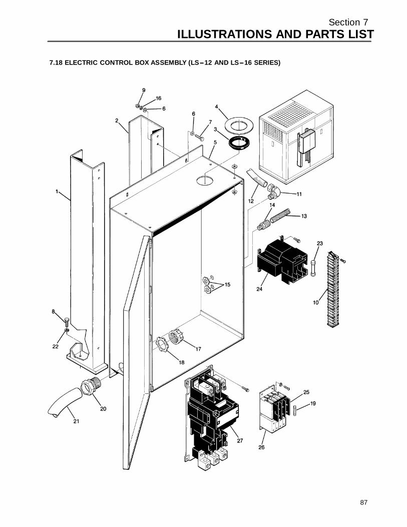
Section 7ILLUSTRATIONS AND PARTS LIST
7.18 ELECTRIC CONTROL BOX ASSEMBLY (LS---12 AND LS---16 SERIES)
87
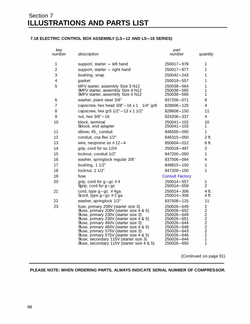
Section 7ILLUSTRATIONS AND PARTS LIST
7.18 ELECTRIC CONTROL BOX ASSEMBLY (LS---12 AND LS---16 SERIES)
key partnumber description number quantity
1 support, starter --- left hand 250017---978 12 support, starter --- right hand 250017---977 13 bushing, snap 250042---243 14 gasket 250019---557 15 MFV starter, assembly Size 3 N12 250038---564 1
SMFV starter, assembly Size 4 N12 250038---565 1SMFV starter, assembly Size 5 N12 250038---566 1
6 washer, plaint steel 3/8” 837206---071 87 capscrew, hex head 3/8”---16 x 1 1/4” gr8 828606---125 48 capscrew, hex gr5 1/2”---13 x 1 1/2” 828608---150 119 nut, hex 3/8”---16 824206---337 4
10 block, terminal 250041---102 10Sblock, end adapter 250041---103 1
11 elbow, 45_ conduit 846500---050 112 conduit, csa flex 1/2” 846315---050 2 ft.13 wire, neoprene so #12---4 850604---012 6 ft.14 grip, cord for so 12/4 250018---497 215 locknut, conduit 1/2” 847200---050 116 washer, springlock regular 3/8” 837506---094 417 bushing, 1 1/2” 848815---150 118 locknut, 1 1/2” 847200---150 11 9 fuse Consul t Fac tor y20 grip, cord for g---gc #4 250014---557 1
Sgrip, cord for g---gc 250014---559 221 cord, type g---gc #4ga 250014---306 4 ft.
Scord, type g---gc #2 ga 250014---308 4 ft.22 washer, springlock 1/2” 837508---125 1123 fuse, primary 208V (starter size 3) 250026---649 2
Sfuse, primary 208V (starter size 4 & 5) 250006---652 2Sfuse, primary 230V (starter size 3) 250026---649 2Sfuse, primary 230V (starter size 4 & 5) 250026---651 2Sfuse, primary 460V (starter size 3) 250026---644 2Sfuse, primary 460V (starter size 4 & 5) 250026---648 2Sfuse, primary 575V (starter size 3) 250026---643 2Sfuse, primary 575V (starter size 4 & 5) 250026---646 2Sfuse, secondary 115V (starter size 3) 250026---644 1Sfuse, secondary 115V (starter size 4 & 5) 250026---650 1
(Continued on page 91)
PLEASE NOTE: WHEN ORDERING PARTS, ALWAYS INDICATE SERIAL NUMBER OF COMPRESSOR.
88

Section 7ILLUSTRATIONS AND PARTS LIST
89
7.18 ELECTRIC CONTROL BOX ASSEMBLY (LS---12 AND LS---16 SERIES)

Section 7ILLUSTRATIONS AND PARTS LIST
7.18 ELECTRIC CONTROL BOX ASSEMBLY (LS---12 AND LS---16 SERIES) (CONTINUED)
key partnumber description number quantity
24 transformer, 240/480---120V (starter size 3) 250040---184 1S transformer, 240/480---120V(starter size 4 & 5 ) 250040---185 1Stransformer, 208---120V (starter size 3) 250040---184 1Stransformer, 208---120V (starter size 4 & 5) 250040---185 1Stransformer, 575---120V (starter size 3) 250040---184 1Stransformer, 575---120V (starter size 4 & 5) 250040---185 1
25 fuseholder 250023---290 126 starter, open replacement, (size 0) 250021---835 1
Sstarter, open replacement (size 1) 250021---836 1Srelay, overload replacement (size 0) 250021---692 1Srelay, overload replacement (size 1) 250021---693 1
27 starter, open replacement (size 3) 250021---838 1Sstarter, open replacement (size 4 250021---839 1Sstarter, open replacement (size 5) 250038---284 1Scoil, starter replacement (size 3) 250038---578 1Scoil, starter replacement (size 4 250038---579 1Scoil, starter replacement (size 5) 250038---579 1Srelay, overload replacement (size 3) 250040---076 1Srelay, overload replacement (size 4) 250040---077 1Srelay, overload replacement (size 5) 250021---692 1
PLEASE NOTE: WHEN ORDERING PARTS, ALWAYS INDICATE SERIAL NUMBER OF COMPRESSOR.
90
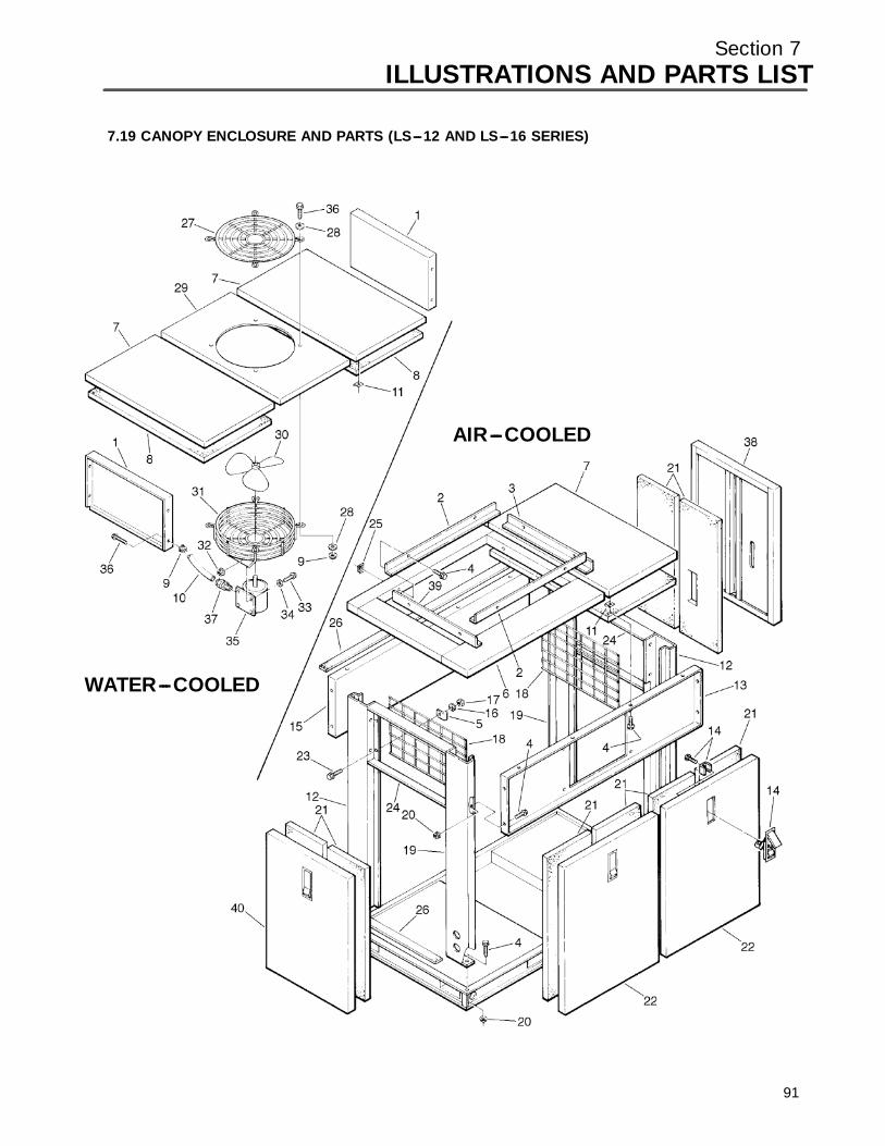
Section 7ILLUSTRATIONS AND PARTS LIST
7.19 CANOPY ENCLOSURE AND PARTS (LS---12 AND LS---16 SERIES)
WATER---COOLED
AIR---COOLED
91

Section 7ILLUSTRATIONS AND PARTS LIST
7.19 CANOPY ENCLOSURE AND PARTS (LS---12 AND LS---16 SERIES)
key partnumber description number quantity
1 panel, enclosure end (water---cooled) 250018---647 2Sgrille, cooler (60 and 75HP) 250018---296 1
2 angle, seal (40 and 50HP) 250018---291 2Sangle, seal (60 and 75HP) 250018---106 2Sangle, seal (100HP) 02250060---870 2
3 angle, seal (40 and 50HP) 250018---291 1Sangle, seal (60 and 75HP 250034---881 1Sangle, seal (100HP) 02250060---871 2
4 screw, hex serrated washer 5/16”---18(water---cooled) 829705---075 44Sscrew, hex serrated washer 5/16”---18(air---cooled) 829705---075 40
5 clamp, wire (air---cooled) 043194 166 frame, roof (40 and 50HP) 250018---268 1
Sframe, roof (60 and 75HP) 250017---865 1Sframe, roof (100HP) 02250043---154 1
7 panel, access roof 250017---309 18 panel, fiberglass roof 250020---012 19 nut, hex flange 5/16” (air---cooled) 825305---283 4
Snut, hex flange 5/16” (water---cooled) 825305---283 1210 wire, neoprene #16---4 850604---016 811 nut, retainer 5/16”---18 861505---140 1612 panel, corner --- right hand 250018---609 213 panel, front side 250017---311 114 latch, adjustable trigger lock 049764 615 panel, back side 250017---312 116 washer, springlock 1/4” 837504---062 1217 nut, hex 1/4” 824204---226 1218 grille, enclosure end (air---cooled) 250018---667 219 panel, corner --- left hand 250018---610 220 nut, hex flanged 5/16” (water---cooled) 825305---283 16
Snut, hex flanged 5/16” (air---cooled) 825305---283 2021 panel, fiberglass door 250020---015 1222 panel, access side 250017---310 423 capscrew, hex 1/4”---20 829104---100 824 panel, end 250018---646 225 nut, retainer 5/16”---18 861405---092 826 felt, weatherstrip 043502 92 ft.27 guard, fan 20” 241137 128 washer, plain 5/16” 838205---071 829 panel, access roof 250017---308 1
(Continued on page 95)
PLEASE NOTE: WHEN ORDERING PARTS, ALWAYS INDICATE SERIAL NUMBER OF COMPRESSOR.
92

Section 7ILLUSTRATIONS AND PARTS LIST
93
7.19 CANOPY ENCLOSURE AND PARTS (LS---12 AND LS---16 SERIES)
WATER---COOLED
AIR---COOLED
Section 7ILLUSTRATIONS AND PARTS LIST
7.19 CANOPY ENCLOSURE AND PARTS (LS---12 AND LS---16 SERIES) (CONTINUED)
key partnumber description number quantity
30 fan, vent 18” 410358 131 guard, exhaust fan 410179 132 nut, hex flange 5/16” 825305---283 433 screw, hex serrated washer 5/16” x 3/4” 829705---075 434 washer, plain 5/16” 838205---071 435 motor, 25HP (230, 460V) 250000---031 136 screw, hex serrated washer 5/16” x 3/4” 829705---075 437 grip, cord 1/2” 250021---321 138 panel, access side special (air---cooled) 250021---260 1
Spanel, access side special (water---cooled) 250034---296 139 angle, seal (40 and 50 HP) 250034---939 1
Sangle, seal (60 and 75 HP) 250034---881 140 panel, access side (air---cooled) 250017---310 1
Spanel, access side (water---cooled) 250034---297 1
PLEASE NOTE: WHEN ORDERING PARTS, ALWAYS INDICATE SERIAL NUMBER OF COMPRESSOR.
94
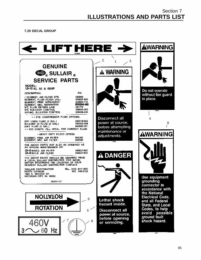
Section 7ILLUSTRATIONS AND PARTS LIST
7.20 DECAL GROUP
12 3
4
5
6
7 8
9
95
Section 7ILLUSTRATIONS AND PARTS LIST
7.20 DECAL GROUP
key partnumber description number quantity
1 decal, fork lifting 241814 42 decal, 12BS maintenance kit (40,50,60HP) 250034---137 13 sign, warning sever fan 049855 24 sign, warning sever fan port 049965 15 sign, danger electrocution 049850 16 decal, rotation 250021---286 17 decal, 460 voltage international (I) 02250069---399 18 decal, earth ground 02250075---046 19 decal, warning ground fault 049852 1
(Continued on page 99)
(I) Compressor voltage may vary. Consult Factory with machine serial number.
PLEASE NOTE: WHEN ORDERING PARTS, ALWAYS INDICATE SERIAL NUMBER OF COMPRESSOR.
96
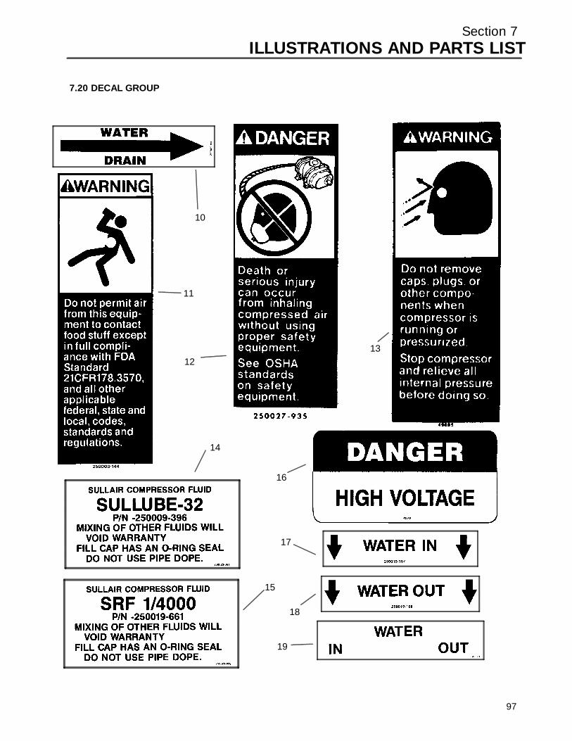
Section 7ILLUSTRATIONS AND PARTS LIST
7.20 DECAL GROUP
10
11
1213
14
15
16
17
18
19
97

Section 7ILLUSTRATIONS AND PARTS LIST
7.20 DECAL GROUP (CONTINUED)
key partnumber description number quantity
10 decal, water drain 250022---810 111 sign, warning “food grade” lube 250003---144 112 sign, danger air breathing 250027---935 113 sign, warning compressor fluid fill cap 049685 114 decal, compressor fluid Sullube 32 250023---361 115 decal, SRF 1/4000 fluid 250022---839 116 decal, danger high voltage 042218 117 decal, “water in” 250019---107 118 decal, “water out” 250019---108 119 decal, water inlet/outlet 049873 1
(Continued on page 101)
PLEASE NOTE: WHEN ORDERING PARTS, ALWAYS INDICATE SERIAL NUMBER OF COMPRESSOR.
98
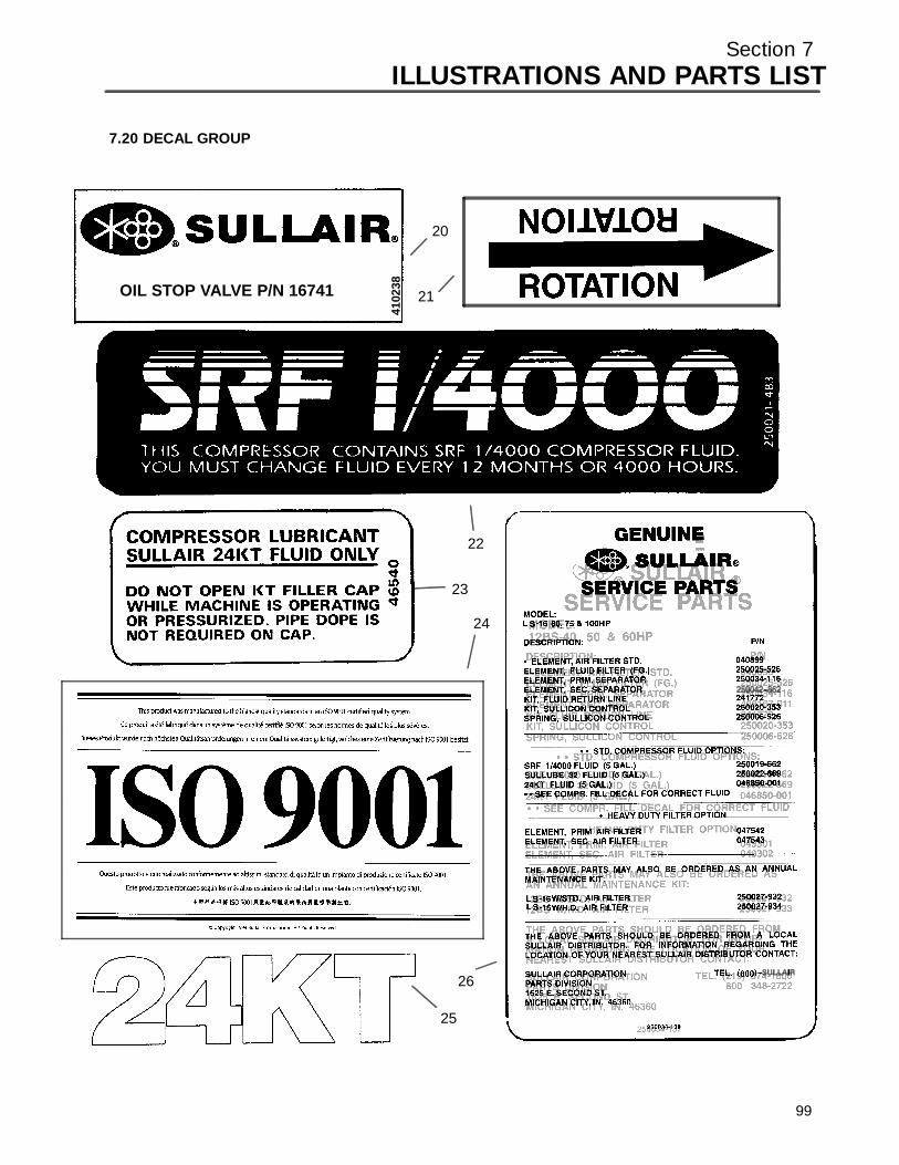
Section 7ILLUSTRATIONS AND PARTS LIST
7.20 DECAL GROUP
OIL STOP VALVE P/N 16741
4102
38
20
21
22
23
24
25
26
99
Section 7ILLUSTRATIONS AND PARTS LIST
7.20 DECAL GROUP (CONTINUED)
key partnumber description number quantity
20 decal, oil stop valve P/N 016741 410238 121 decal, rotation 250021---564 122 decal, SRF 1/4000 logo 250021---483 123 decal, compressor lubricant 046540 124 decal, ISO 9001 02250057---624 125 decal, 24 KT 02250061---016 126 decal, maintenance LS---16 250034---138 1
(Continued on page 103)
PLEASE NOTE: WHEN ORDERING PARTS, ALWAYS INDICATE SERIAL NUMBER OF COMPRESSOR.
100
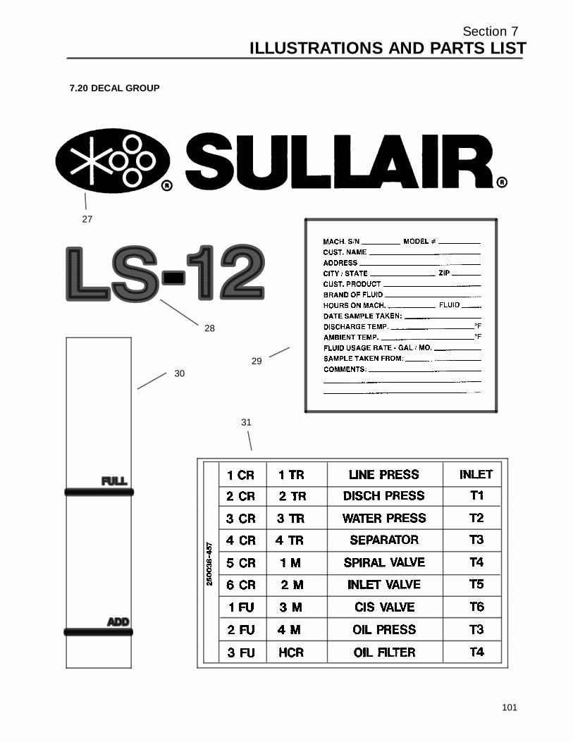
Section 7ILLUSTRATIONS AND PARTS LIST
7.20 DECAL GROUP
27
28
2930
31
101

Section 7ILLUSTRATIONS AND PARTS LIST
7.20 DECAL GROUP (CONTINUED)
key partnumber description number quantity
27 decal, Sullair 02250059---054 228 decal, LS---12 02250061---165 1
Sdecal, LS---16 (not shown) 02250061---170 129 decal, fluid sample 250022---675 130 decal, gauge fluid level 250020---730 131 decal, electrical component 250038---457 132 decal, instrument pnl
universal (not shown) 02250051---301 133 decal, instument pnl
universal (not shown) 02250051---303 134 decal, instrument pnl
universal---dual cntrl (not shown) 02250059---410 1
PLEASE NOTE: WHEN ORDERING PARTS, ALWAYS INDICATE SERIAL NUMBER OF COMPRESSOR.
102
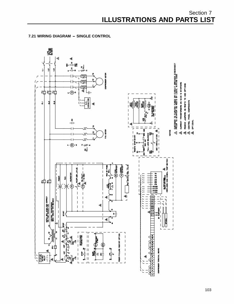
Section 7ILLUSTRATIONS AND PARTS LIST
7.21 WIRING DIAGRAM --- SINGLE CONTROL
103

Section 7ILLUSTRATIONS AND PARTS LIST
7.22 WIRING DIAGRAM --- SINGLE CONTROL WITH ANNUNICATOR
104

Section 7ILLUSTRATIONS AND PARTS LIST
7.23 WIRING DIAGRAM --- DUAL CONTROL
105
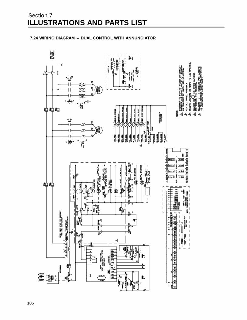
Section 7ILLUSTRATIONS AND PARTS LIST
7.24 WIRING DIAGRAM --- DUAL CONTROL WITH ANNUNCIATOR
106
WORLDWIDE SALES AND SERVICE
R
SULLAIR EUROPE, S.A.Chemin de Genas BP 63969800 Saint Priest, FranceTelephone: 33---72232425
SULLAIR CORPORATIONSubsidiary of Sundstrand Corporation
3700 East Michigan BoulevardMichigan City, Indiana 46360 U.S.A.
Telephone: 1---800---SULLAIR (U.S.A. Only) or1---219---879---5451
SULLAIR ASIA, LTD.ROOM 2304A
Shartex Plaza Ctr.No. 88 Zun Yi Nan Rd.
Shanghai, P.R.C.Telephone: 21---2192066
Fax: (219) 874---1273Fax: (219) 874---1835 (Parts)
Fax: (219) 874---1805 (Service)
Fax: 21---2196568
Fax: 33---78907168
Printed in U.S.A.
Specifications Subject ToChange Without Prior Notice