Embed Size (px)
Citation preview

NREL is a national laboratory of the U.S. Department of Energy Office of Energy Efficiency & Renewable Energy Operated by the Alliance for Sustainable Energy, LLC
This report is available at no cost from the National Renewable Energy Laboratory (NREL) at www.nrel.gov/publications.
Contract No. DE-AC36-08GO28308
Inclusion of Structural Flexibility in Design Load Analysis for Wave Energy Converters Preprint Yi Guo, Yi-Hsiang Yu, Jennifer van Rij, and Nathan Tom National Renewable Energy Laboratory
To be presented at European Wave and Tidal Energy Conference Cork, Ireland August 27−September 1, 2017
Conference Paper NREL/CP-5000-68923 August 2017
NOTICE
The submitted manuscript has been offered by an employee of the Alliance for Sustainable Energy, LLC (Alliance), a contractor of the US Government under Contract No. DE-AC36-08GO28308. Accordingly, the US Government and Alliance retain a nonexclusive royalty-free license to publish or reproduce the published form of this contribution, or allow others to do so, for US Government purposes.
This report was prepared as an account of work sponsored by an agency of the United States government. Neither the United States government nor any agency thereof, nor any of their employees, makes any warranty, express or implied, or assumes any legal liability or responsibility for the accuracy, completeness, or usefulness of any information, apparatus, product, or process disclosed, or represents that its use would not infringe privately owned rights. Reference herein to any specific commercial product, process, or service by trade name, trademark, manufacturer, or otherwise does not necessarily constitute or imply its endorsement, recommendation, or favoring by the United States government or any agency thereof. The views and opinions of authors expressed herein do not necessarily state or reflect those of the United States government or any agency thereof.
This report is available at no cost from the National Renewable Energy Laboratory (NREL) at www.nrel.gov/publications.
Available electronically at SciTech Connect http:/www.osti.gov/scitech
Available for a processing fee to U.S. Department of Energy and its contractors, in paper, from:
U.S. Department of Energy Office of Scientific and Technical Information P.O. Box 62 Oak Ridge, TN 37831-0062 OSTI http://www.osti.gov Phone: 865.576.8401 Fax: 865.576.5728 Email: [email protected]
Available for sale to the public, in paper, from:
U.S. Department of Commerce National Technical Information Service 5301 Shawnee Road Alexandria, VA 22312 NTIS http://www.ntis.gov Phone: 800.553.6847 or 703.605.6000 Fax: 703.605.6900 Email: [email protected]
Cover Photos by Dennis Schroeder: (left to right) NREL 26173, NREL 18302, NREL 19758, NREL 29642, NREL 19795.
NREL prints on paper that contains recycled content.

Inclusion of Structural Flexibility in Design Load Analysis for Wave Energy Converters
Yi Guo National Renewable Energy Laboratory
15013 Denver West Pkwy, Golden, CO, 80401, United States E-mail: [email protected]
Jennifer van Rij National Renewable Energy Laboratory
15013 Denver West Pkwy, Golden, CO, 80401, United States E-mail: [email protected]
Yi-Hsiang Yu National Renewable Energy Laboratory
15013 Denver West Pkwy, Golden, CO, 80401, United States E-mail: [email protected]
Nathan Tom National Renewable Energy Laboratory
15013 Denver West Pkwy, Golden, CO, 80401, United States E-mail: [email protected]
Abstract—Hydroelastic interactions, caused by ocean wave loading on wave energy devices with deformable structures, are studied in the time domain. A midfidelity, hybrid modeling approach of rigid-body and flexible-body dynamics is developed and implemented in an open-source simulation tool for wave energy converters (WEC-Sim) to simulate the dynamic responses of wave energy converter component structural deformations under wave loading. A generalized coordinate system, including degrees of freedom associated with rigid bodies, structural modes, and constraints connecting multiple bodies, is utilized. A simplified method of calculating stress loads and sectional bending moments is implemented, with the purpose of sizing and designing wave energy converters. Results calculated using the method presented are verified with those of high-fidelity fluid-structure interaction simulations, as well as low-fidelity, frequency-domain, boundary element method analysis.
Index Terms—Wave energy converter, structural flexibility, design, dynamics, and modal analysis
I. INTRODUCTION
Harvesting energy from the ocean has attracted increased research attention in recent decades [1], [2]. Numerous forms of wave energy converters (WECs) have been designed to capture the energy of the ocean surface waves and convert it to electricity [3]. Compared to other renewable energy sources, such as wind and solar, the wave energy resource is less seasonal and offers the highest energy density [4]. However, wave energy technologies are still in the early stages of research and a physical understanding for optimizing WEC reliability and lowering the cost of energy is still evolving.
Structural costs have been identified as one of the primary cost drivers for WECs. As a result, accurate load predictions during the design process are essential to further reduce the cost of WECs. Furthermore, several new concepts incorporating composite materials and flexible WEC components, rather than the traditional steel/rigid-body designs, have recently been proposed as potential cost reduction pathways. Consequently, WEC structural flexibility, as well as the resulting fluid structure interactions (FSI) of the WEC system, have become increasingly important aspects to WEC
design. Therefore, when considering the interaction between wave loading and WEC structural dynamics, an accurate and computationally efficient coupled approach for structural and hydrodynamic analyses is needed for WEC design.
The most widely used approach for FSI modeling is to couple computational fluid dynamics with finite element analysis. Another direct method to modeling the structural-hydrodynamic behavior of flexible WEC components is to simultaneously model the frequency-domain hydrodynamic boundary value problem with the elastic finite element response [5]. However, both approaches are computationally expensive and generally unsuitable in the initial phases of WEC design. Alternatively, a reduced-order, generalized modes method may be adopted, in which additional degrees of freedom (DOF) associated with a preselected set of generalized body modes, are included in the frequency-domain hydrodynamic boundary value problem [6]. These generalized modes are typically the natural mode shapes of the deformable structures; however, approximate mode shapes, such as Legendre polynomials, may also be used [6]. Hydrodynamic loads corresponding to radiation (i.e., added mass and damping coefficients) and wave excitation are then evaluated based on a unit modal response. Newman employed the generalized modes method to analyze the deformation of barges and a vertical cylinder using WAMIT, a frequency-domain, boundary-element-based potential flow solver [6], [7]. A similar study was conducted to analyze a very flexible barge in the time domain utilizing hydrodynamic coefficients from a frequency domain potential flow solution and a state-space model to approximate the radiation and excitation impulse response functions [8]–[10].
The objective of this research is to use and verify the generalized modes method to calculate wave-induced structural loads and flexible body dynamics for WEC applications.
In this study, the generalized modes method is adopted in WEC-Sim, a radiation-diffraction-based time-domain numerical model that calculates the dynamics of WEC devices comprised of rigid bodies, power-take-off (PTO) systems,
1
This report is available at no cost from the National Renewable Energy Laboratory at www.nrel.gov/publications.
- - - -
and mooring systems [11]. The generalized modes method is also used to recover body component stress and bending moments, using an approach based on the linear superposition of stresses/bending moments in modal coordinates [12]. The modal stresses/bending moments corresponding to the component modes can be calculated either analytically or by finite element analyses (FEA). After describing the process of implementing modes derived from FEA, and the dynamics model used to combine rigid and flexible body simulations, the resulting numerical method is applied to simulate a barge and a vertical cylinder, the results of which are compared to high-fidelity coupled hydro-elastic simulations. Finally, future research applications for the generalized body modes methods, including mooring and PTO, are discussed.
II. COMPONENT SPECIFICATIONS
Two flexible structures are considered in this study, a barge and a column, each of which are based on Newman’s original examples in [6] and further considered in [1]. Both structures may be considered as simplified representations of WEC components—a “Wave-Carpet”-type device and a monopile for a single-body point absorber. Parameters for these structures are listed in Table I.
TABLE I PARAMETERS FOR THE BARGE AND COLUMN
Property Units Barge Column
Mass kg 4.000 × 10⁶ 3.142 × 10⁷
Density kg/m2 500.000 500.000 Cross-Sectional Area m2 100.000 341.159
Young’s Modulus MP a 30.720 4800.000 Area Moment of Inertia m2 833.333 7853.982
Length m 80.0 200.0 Poisson’s Ratio − 0.3 0.3
III. FLEXIBLE MULTIBODY DYNAMIC MODELING
This section describes the formulation used to model flexible multibody dynamics for WEC devices. The system considers both the rigid-body motions and the structural deformations of WEC components. The dynamic, structural deformations of WEC bodies are evaluated in modal coordinates, whereas rigid body dynamics are calculated in physical coordinates. Assuming the rigid-body motions may be decoupled from the structural deformation significantly reduces computation time and modeling complexity. With the assumption of linear structure with small deformation, the modal properties of flexible bodies may be simply obtained with closed-form analytic expressions or finite element analysis, and the rigid body system is discretized using a classical rigid body dynamics approach. The resulting dynamic response of the WEC device then combines the rigid body motions with the flexible deformations.
The equation of motion of the hydro-elastic-multibody dynamics of WEC is formulated as t(M + A∞)x+ D(t − τ )x(τ)dτ +C x − 1 ρACDx|x|+
0 2 Kx = F
(1) where C = CM + CPTO + Cld + Cs, K = KM + KPTO + KB + Ks, and F = Fext + FME . Throughout this paper, M, C, and K denote mass, damping, and stiffness matrices. F is the excitation force vector. The subscripts f , r, and s represent rigid body, flexible body, and their hybrid system, respectively. Subscripts M , PTO, ME, ext, and B denote mooring, power take-off, Morison, excitation, and buoyancy. A∞ is the added mass terms for the structure.
M = diag Mr,1, Mf,1, Mr,2, Mf,2, . . . , Mf,N (2)
Ks = diag Kr,1, Kf,1, Kr,2, Kf,2, . . . , kf,N (3)
Cs = diag [Cr,1, 0, Cr,2, 0, . . . , Cr,N , 0] (4)
F = Fr,1, Ff,1, Fr,2, Ff,2, . . . , Fr,N , Ff,N (5)
where Mf = ΦT Mf Φ and Kf = ΦT Kf Φ are diagonal matrices. Excitation force in the modal coordinates is Ff = ΦT Ff .
Here, x = {z1, z2, ..., zN }T , where N is the total number of bodies in the system. Each displacement vector consists of rigid and flexible DOFs as
z = {p, q} = {x, y, z, θx, θy , θz , q1, q2, . . . , qm} (6)
Rigid Flexible
In the system environment, m is a user-defined variable that depends on the body selection. In other words, the number of flexible modes for each body can be different. The total DOFs eNfor the system, therefore, equals 6N + j=1 m(j) includingeN6N rigid-body DOFs and j=1 m(j) flexible-body DOFs.
Assuming the dynamic response, u, is the linear superposition of system’s eigenvectors, such as
u = Φq (7)
where q = {q1, q2, . . . , qm}T , Φ = [Φ1, Φ2, . . . , Φm], and m is the total number of eigenvectors.
Similar to Eq. 7, the dynamic stress response of any flexible WEC body, Ξ, is the linear superposition of the system’s stress distribution in the modal coordinate, such as
Ξ = Υq (8)
where Υ is the stress vector of the flexible body in the modal coordinates.
The bending moment of the same flexible body, T, is
T = Λq (9)
where Λ is the bending moment vector of the flexible body in the modal coordinate.
2
This report is available at no cost from the National Renewable Energy Laboratory at www.nrel.gov/publications.

- -
- -
Eigenvalue analysis of WEC structure
Construct mass, sti�ness, & damping matrices
Supply structural modes to WAMIT
Hydrodynamic analysis in WAMIT
Natural frequencies/
Mode shapes
Flexible multibody model in WEC-Sim
Mass, sti�ness, & damping
Hydrodynamic coe!cients
Dynamic response & loadsMoments & stress
Modal stress/moment analysis
Natural frequencies/
Mode shapes
Fig. 3. Finite element model of the column established in ANSYS
TABLE II
In WEC-Sim, Eq. 1 has been formulated in a state-space form as follows
0, I
y = y+−M−1K, −M−1C
AA⎡ ⎤ 0 (10) ⎣ t ⎦M−1[A∞x− D(t − τ)x(τ)dτ+
0 1 ρACDx|x| + Fext + FME ]2
BB(t)
where y = [x; x]T and AA is the time-invariant coefficient matrix. BB is the time-varying excitation vector. Terms A∞x, t 1D(t − τ)x(τ)dτ , and ρADx|x| are approximated using 0 2
solutions at previous time steps. Eq. 10 is solved using ODE4 in MATLAB.
The proposed modeling approach has been implemented in WEC-Sim. Solving the WEC dynamic response consists of multiple major steps, including 1) modal analysis of the studied WEC to identify a set of system natural frequencies and corresponding mode shapes, 2) construct discretized mass and impedance matrices using these structural modes, 3) include these additional degrees of freedom in WAMIT as generalized modes to calculate the additional hydrodynamic coefficients to capture the structural-fluid interaction, and 4) import the hydrodynamic coefficients to WEC-Sim and conduct dynamic analysis of the hybrid rigid and flexible body system. These key steps are also illustrated in Fig. 4.
Fig. 1. Process of a structural-fluid analysis of WEC devices
IV. FINITE ELEMENT MODELING
Finite element models of the barge and column are created in ANSYS as shown in Fig. 2 and Fig. 3, respectively. Both models were built using beam elements (BEAM188), with three nodes per element. Mesh convergence studies were performed, resulting in a total of 80 beam elements for each
structure. The free-free boundary conditions are applied to the barge model and the first four modes are then calculated with modal analysis. For the column, free-fixed boundary conditions are used to model the rigid connection to the seafloor, and modal analysis is used to obtain the first four modes. Although both structures could potentially be modeled with either beam or solid elements, the beam-element model is advantageous in this application, because the element rotational DOFs may be exported along with the load and moment distributions. The modal mass and stiffness matrices, Mf = ΦT Mf Φ and Kf = ΦT Kf Φ, as input in WAMIT, are listed in Table II.
Fig. 2. Finite element model of the barge established in ANSYS
MODAL MASS AND STIFFNESS PROPERTIES OF THE BARGE AND COLUMN, AS CALCULATED USING FEA
Modes Barge Column
Mass (kg) Stiffness (N/m) Mass (kg) Stiffness (N/m) 1st
2nd
3rd
4th
1.079 × 10⁶
1.210 × 10⁶
2.392 × 10⁶
1.831 × 10⁶
7.904 × 10⁶
8.267 × 10⁶
8.821 × 10⁶
9.597 × 10⁶
6.077 × 10⁶
4.383 × 10⁷
2.741 × 10⁸
4.664 × 10⁸
1.447 × 10⁷
5.560 × 10⁸
4.223 × 10⁹
1.560 × 10¹⁰
3
This report is available at no cost from the National Renewable Energy Laboratory at www.nrel.gov/publications.
V. RESULT CORRELATION WITH HIGH-FIDELITY CODES AND EXPERIMENTAL DATA
The presented method is validated by correlating results with full-scale computational fluid dynamics analysis considering FSI in STAR-CCM+ and the frequency-domain analysis in WAMIT. STAR-CCM+ [13], one of the highest-fidelity computational fluid dynamics-finite element analysis (FEA) codes, was utilized in this study. FSI is modeled by implicitly coupling the unsteady RANS solver with a FVA solver, within the same STAR-CCM+ simulation.
WAMIT performs boundary element analysis for simulating WEC’s linearized hydrodynamic response in the frequency domain. The steps of using generalized body modes to estimate wave loads on deformable bodies are documented in the WAMIT user manual [7]. Details on these two computational models of the studied articles are discussed in [1].
A. Flexible barge
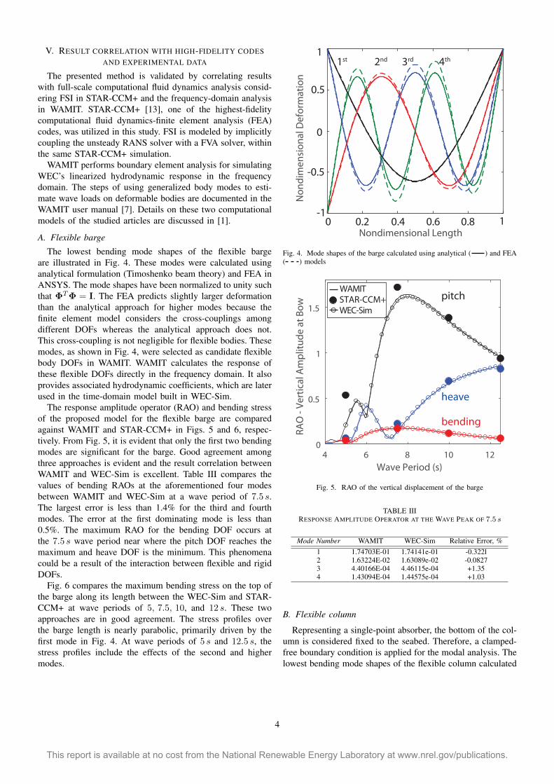
The lowest bending mode shapes of the flexible barge are illustrated in Fig. 4. These modes were calculated using analytical formulation (Timoshenko beam theory) and FEA in ANSYS. The mode shapes have been normalized to unity such that ΦT Φ = I. The FEA predicts slightly larger deformation than the analytical approach for higher modes because the finite element model considers the cross-couplings among different DOFs whereas the analytical approach does not. This cross-coupling is not negligible for flexible bodies. These modes, as shown in Fig. 4, were selected as candidate flexible body DOFs in WAMIT. WAMIT calculates the response of these flexible DOFs directly in the frequency domain. It also provides associated hydrodynamic coefficients, which are later used in the time-domain model built in WEC-Sim.
The response amplitude operator (RAO) and bending stress of the proposed model for the flexible barge are compared against WAMIT and STAR-CCM+ in Figs. 5 and 6, respectively. From Fig. 5, it is evident that only the first two bending modes are significant for the barge. Good agreement among three approaches is evident and the result correlation between WAMIT and WEC-Sim is excellent. Table III compares the values of bending RAOs at the aforementioned four modes between WAMIT and WEC-Sim at a wave period of 7.5 s. The largest error is less than 1.4% for the third and fourth modes. The error at the first dominating mode is less than 0.5%. The maximum RAO for the bending DOF occurs at the 7.5 s wave period near where the pitch DOF reaches the maximum and heave DOF is the minimum. This phenomena could be a result of the interaction between flexible and rigid DOFs.
Fig. 6 compares the maximum bending stress on the top of the barge along its length between the WEC-Sim and STARCCM+ at wave periods of 5, 7.5, 10, and 12 s. These two approaches are in good agreement. The stress profiles over the barge length is nearly parabolic, primarily driven by the first mode in Fig. 4. At wave periods of 5 s and 12.5 s, the stress profiles include the effects of the second and higher modes.
Nondimensional Length
No
nd
ime
nsi
on
al D
efo
rma
tio
n
0 10.2 0.4 0.6 0.8
1
-1
0
-0.5
0.5
2nd 3rd 4th1st
Fig. 4. Mode shapes of the barge calculated using analytical ( ) and FEA ( ) models
4 6 8 10 12
Wave Period (s)
0
0.5
1
1.5R
AO
- V
ert
ica
l Am
pli
tud
e a
t B
ow
pitch
heave
bending
STAR-CCM+WAMIT
WEC-Sim
Fig. 5. RAO of the vertical displacement of the barge
TABLE III RESPONSE AMPLITUDE OPERATOR AT THE WAVE PEAK OF 7.5 s
Mode Number WAMIT WEC-Sim Relative Error, % 1 1.74703E-01 1.74141e-01 -0.322l 2 1.63224E-02 1.63089e-02 -0.0827 3 4.40166E-04 4.46115e-04 +1.35 4 1.43094E-04 1.44575e-04 +1.03
B. Flexible column
Representing a single-point absorber, the bottom of the column is considered fixed to the seabed. Therefore, a clamped-free boundary condition is applied for the modal analysis. The lowest bending mode shapes of the flexible column calculated
4
This report is available at no cost from the National Renewable Energy Laboratory at www.nrel.gov/publications.

0 20 40 60 80
Length (m)
0
0.01
0.02
0.03
0.04
0.05
0.06
0.07M
axi
mu
m B
en
din
g S
tre
ss (
MP
a)
STAR-CCM+WEC-Sim
5 s
7.5 s
10 s
12.5 s
the STAR-CCM+ results. Being able to calculate these stress cycles in the time domain is an important step for the life calculations of WEC structures.
0 0.2 0.4 0.6 0.8 1-1
-0.5
0
0.5
1
Nondimensional Length
No
nd
ime
nsi
on
al D
efo
rma
tio
n
2nd
3rd
4th
1st
Fig. 7. Mode shapes of the column calculated using analytical ( ) and FEA ( ) models
Fig. 6. Maximum bending stress amplitude along the barge at various wave periods
using the analytical and FEA approaches are illustrated in Fig. 7. The Timoshenko beam theory predicts almost the identical modal response of the column as FEA in ANSYS. Because the column is much stiffer than the barge, the cross-coupling among different DOFs is very little. Thus, the analytical results of the column match the FEA results very well.
The RAO of the proposed model for the flexible column is compared against WAMIT and STAR-CCM+ in Fig. 8. Viscous damping effects with CD = 1 along the structure have be considered for the column case. As shown in Fig. 8, the first bending mode dominates the response for the column compared to higher modes (at least one order of magnitude higher) and reaches the maximum near the 8.4 s wave period. The result correlation among all three approaches is excellent.
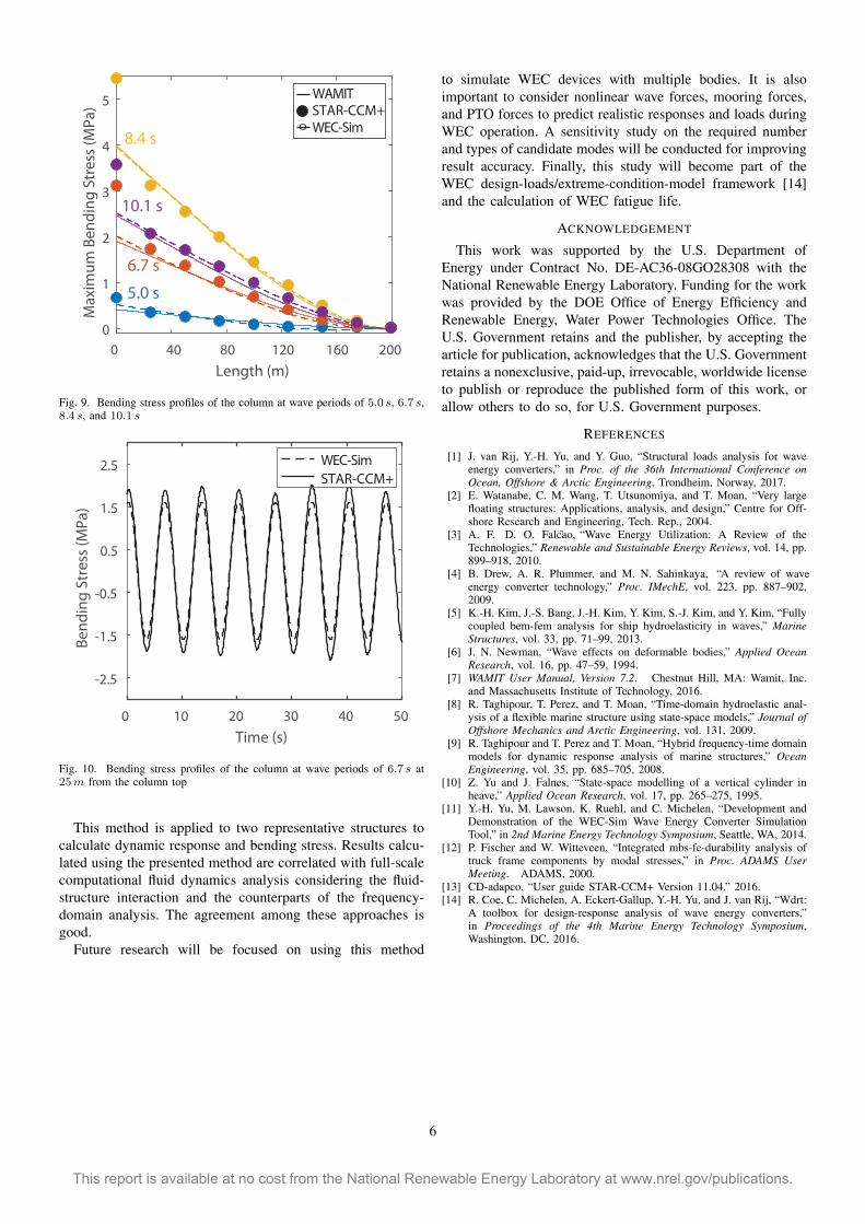
Fig. 9 compares the bending stress profiles of the column along its height among WEC-Sim, WAMIT, and STAR-CCM+ at wave periods of 5.0, 6.7, 8.4, and 10.1 s. The agreement among all three approaches is good. The stress profiles are primarily determined by the first bending mode in Fig. 7 with small effects from higher modes. Small differences are present between the high-fidelity STAR-CCM+ results and generalized body modes approach in WAMIT and WEC-Sim particularly near the top of the column. There are multiple reasons that contribute to the result differences. For instance, the STARCCM+ model considers nonlinear wave effects, whereas the other two do not, and STAR-CCM+ requires a longer transient time to reach the system’s steady state. Additional discussions on the potential causes of these wave effects can be found in [1].
Fig. 10 compares the time history of the oscillating bending stress of the column calculated using WEC-Sim and STARCCM+ at a wave period of 6.7 s under a regular wave with a time ramp up to 50 s. The agreement between these two approaches is reasonable, with slightly stronger oscillation in
Fig. 8. RAO of the column displacement at the waterline for the first four bending modes
VI. CONCLUSIONS
A flexible multibody dynamics modeling approach is formulated and implemented in WEC-Sim, the open-source, time-domain simulation tool of WECs. This time-domain approach considers the structural flexibility of WEC components and provides a fast solution for WEC dynamic response, stress, and loads under the effects of wave loading.
5 6 7 8 9 10 11
Wave Period (s)
0
0.5
1
1.5
RA
O -
Dis
pla
cem
en
t a
t W
ate
rlin
e STAR-CCM+WAMIT
WEC-Sim
5
This report is available at no cost from the National Renewable Energy Laboratory at www.nrel.gov/publications.
160
Length (m)
0
1
2
3
4
5M
axi
mu
m B
en
din
g S
tre
ss (
MP
a) STAR-CCM+
WAMIT
WEC-Sim
5.0 s
6.7 s
8.4 s
10.1 s
20012080400
Fig. 9. Bending stress profiles of the column at wave periods of 5.0 s, 6.7 s, 8.4 s, and 10.1 s
0 10 20 30 40 50
Time (s)
-2.5
-1.5
-0.5
0.5
1.5
2.5
Be
nd
ing
Str
ess
(M
Pa
)
WEC-Sim
STAR-CCM+
Fig. 10. Bending stress profiles of the column at wave periods of 6.7 s at 25 m from the column top
This method is applied to two representative structures to calculate dynamic response and bending stress. Results calculated using the presented method are correlated with full-scale computational fluid dynamics analysis considering the fluid-structure interaction and the counterparts of the frequency-domain analysis. The agreement among these approaches is good.
Future research will be focused on using this method
to simulate WEC devices with multiple bodies. It is also important to consider nonlinear wave forces, mooring forces, and PTO forces to predict realistic responses and loads during WEC operation. A sensitivity study on the required number and types of candidate modes will be conducted for improving result accuracy. Finally, this study will become part of the WEC design-loads/extreme-condition-model framework [14] and the calculation of WEC fatigue life.
ACKNOWLEDGEMENT
This work was supported by the U.S. Department of Energy under Contract No. DE-AC36-08GO28308 with the National Renewable Energy Laboratory. Funding for the work was provided by the DOE Office of Energy Efficiency and Renewable Energy, Water Power Technologies Office. The U.S. Government retains and the publisher, by accepting the article for publication, acknowledges that the U.S. Government retains a nonexclusive, paid-up, irrevocable, worldwide license to publish or reproduce the published form of this work, or allow others to do so, for U.S. Government purposes.
REFERENCES
[1] J. van Rij, Y.-H. Yu, and Y. Guo, “Structural loads analysis for wave energy converters,” in Proc. of the 36th International Conference onOcean, Offshore & Arctic Engineering, Trondheim, Norway, 2017.
[2] E. Watanabe, C. M. Wang, T. Utsunomiya, and T. Moan, “Very large floating structures: Applications, analysis, and design,” Centre for Offshore Research and Engineering, Tech. Rep., 2004.
[3] A. F. D. O. Falcao,˜ “Wave Energy Utilization: A Review of the Technologies,” Renewable and Sustainable Energy Reviews, vol. 14, pp. 899–918, 2010.
[4] B. Drew, A. R. Plummer, and M. N. Sahinkaya, “A review of wave energy converter technology,” Proc. IMechE, vol. 223, pp. 887–902, 2009.
[5] K.-H. Kim, J.-S. Bang, J.-H. Kim, Y. Kim, S.-J. Kim, and Y. Kim, “Fully coupled bem-fem analysis for ship hydroelasticity in waves,” Marine Structures, vol. 33, pp. 71–99, 2013.
[6] J. N. Newman, “Wave effects on deformable bodies,” Applied Ocean Research, vol. 16, pp. 47–59, 1994.
[7] WAMIT User Manual, Version 7.2. Chestnut Hill, MA: Wamit, Inc. and Massachusetts Institute of Technology, 2016.
[8] R. Taghipour, T. Perez, and T. Moan, “Time-domain hydroelastic analysis of a flexible marine structure using state-space models,” Journal of Offshore Mechanics and Arctic Engineering, vol. 131, 2009.
[9] R. Taghipour and T. Perez and T. Moan, “Hybrid frequency-time domain models for dynamic response analysis of marine structures,” Ocean Engineering, vol. 35, pp. 685–705, 2008.
[10] Z. Yu and J. Falnes, “State-space modelling of a vertical cylinder in heave,” Applied Ocean Research, vol. 17, pp. 265–275, 1995.
[11] Y.-H. Yu, M. Lawson, K. Ruehl, and C. Michelen, “Development and Demonstration of the WEC-Sim Wave Energy Converter Simulation Tool,” in 2nd Marine Energy Technology Symposium, Seattle, WA, 2014.
[12] P. Fischer and W. Witteveen, “Integrated mbs-fe-durability analysis of truck frame components by modal stresses,” in Proc. ADAMS User Meeting. ADAMS, 2000.
[13] CD-adapco, “User guide STAR-CCM+ Version 11.04,” 2016. [14] R. Coe, C. Michelen, A. Eckert-Gallup, Y.-H. Yu, and J. van Rij, “Wdrt:
A toolbox for design-response analysis of wave energy converters,” in Proceedings of the 4th Marine Energy Technology Symposium, Washington, DC, 2016.
6
This report is available at no cost from the National Renewable Energy Laboratory at www.nrel.gov/publications.