Embed Size (px)
Citation preview
1
An Investigation into the Effects of
Sterilisation on Poly(caprolactone) for
In Vitro and In Vivo Medical Use
A Dissertation Submitted to the University of Manchester for the Degree of Master of
Science by Research in the Faculty of Engineering and Physical Sciences
2013
Adam Philip Strange
School of Materials
2
Declaration
The author declares that no portion of the work referred to in the dissertation has been
submitted in support of an application for another degree or qualification of this or any
other university or other institute of learning.
Copyright
i. The author of this dissertation (including any appendices and/or schedules to this
dissertation) owns certain copyright or related rights in it (the “Copyright”) and he
asserts his rights to be recognised as the author under the relevant laws. He has also
given The University of Manchester certain rights to use such Copyright, including for
administrative purposes.
ii. Copies of this dissertation, either in full or in extracts and whether in hard or
electronic copy, may be made only in accordance with the Copyright, Designs and
Patents Act 1988 (as amended) and regulations issued under it or, where appropriate,
in accordance with licensing agreements which the University has entered into. This
page must form part of any such copies made.
iii. The ownership of certain Copyright, patents, designs, trademarks and other
intellectual property (the “Intellectual Property”) and any reproductions of copyright
works in the dissertation, for example graphs and tables (“Reproductions”), which may
be described in this dissertation, may not be fully owned by the author and may be
partially owned by third parties. Such Intellectual Property and Reproductions cannot
and must not be made available for use without the prior written permission of the
owner(s) of the relevant Intellectual Property and/or Reproductions and the author.
iv. Further information on the conditions under which disclosure, publication and
commercialisation of this dissertation, the Copyright and any Intellectual Property
and/or Reproductions described in it may take place is available in the University IP
Policy in any relevant Dissertation restriction declarations deposited in the University
Library, The University Library’s regulations and in The University’s Guidance for the
Presentation of Dissertations and with the consent of the author.
3
CONTENTS
Declaration ................................................................................................................................................... 2
Copyright ...................................................................................................................................................... 2
Contents ............................................................................................................................................................. 3
Abstract .............................................................................................................................................................. 4
Chapter 1 Introduction, Literature Review and Aims ..................................................................... 5
1.1 New Introduction ............................................................................................................................... 5
1.2 Electrospinning ................................................................................................................................... 8
1.3 Polymers for Electrospinning ..................................................................................................... 13
1.4 Sterilisation ........................................................................................................................................ 18
Chapter 2 : Materials and Methods ....................................................................................................... 30
Chapter 3 : Results ....................................................................................................................................... 36
3.1 Fourier-Transform Infrared Spectroscopy ............................................................................ 36
3.2 Differential Scanning Calorimetry ............................................................................................. 39
3.3 Tensile Testing .................................................................................................................................. 41
3.4 Cell Culture ......................................................................................................................................... 44
3.5 Gel Permeation Chromatography .............................................................................................. 46
3.6 Water Contact Angle ....................................................................................................................... 47
3.7 Scanning Electron Microscopy .................................................................................................... 49
Chapter 4 : Discussion and Conclusion ................................................................................................ 54
Appendix A – FTIR Data ............................................................................................................................. 66
Appendix B – GPC Data .............................................................................................................................. 71
Appendix C – Contact Angle Data ........................................................................................................... 73
Chapter 5 : References ............................................................................................................................... 74
Word Count: 17,126
4
Abstract
The requirements on any implanted biomaterial are strict. Amongst these, the
biomaterial must be sterile. In order to achieve this, there are several methods which
are recognised as being suitable for sterilisation, amongst which are gamma irradiation
and ethylene oxide. Poly(caprolactone) is a polymer which is regularly used as a
biomaterial; it is safe, readily available, has good handling properties and is
biocompatible. This study sought to investigate the effects of two lab based sterilisation
methods, ethanol and ultraviolet irradiation, and compare them to the effects of
sterilisation by gamma irradiation and ethylene oxide sterilisation. Significant changes
in physical behaviour, such as mechanical properties and cell culture response were
reported. There were minimal gross chemical affects reported. No one sterilisation
method could fully replicate the effects of another, but in some areas suitable
replacements could be found; ethylene oxide, for example, was found to be a poor
scaffold in terms of cell culture. Overall, it was decided that papers which report the
effects of one type of sterilisation on PCL can only be used in certain circumstances to
decide the effects of another type of sterilisation. The important factor is to look at
which particular tests are being run to determine whether or not a particular
sterilisation method is suitable.
5
Chapter 1 Introduction, Literature Review and Aims
1.1 Introduction
Any non-living device or construct which comes into contact with the body is known as
a biomaterial. They range from mundane low-risk disposable items, for example
plasters and bandages (usually known as Class I), to complexly engineered long-term
devices such as total hip replacements and cardiac pacemakers (Class III.) Typically,
these biomaterials can be grouped into several classes, depending on the properties of
the role they must fulfil, and the dangers posed to patients should issues arise. The
clinical need for safe and effective implanted biomaterials (Classes II and III) worldwide
cannot be underestimated; billions of dollars each year is spent on surgeries and after-
care of patients with similarly large amounts of money being spent on researching new
and improved biomaterials. This research translates into a moderate number of new
devices being approved for full clinical use each year; the Food and Drug Administration
(FDA) in the United States permitted 47 devices in 2012, its highest number in recent
years (FDA 2012). Similar numbers of devices have been approved by the Medicines
and Healthcare Regulatory Agency (MHRA, the regulatory body of the United Kingdom)
per year, with 7774 devices permitted for “full clinical use” as of June 2013 (MHRA
2013). Patient confidence is maintained by regulatory bodies such as these, and the
rigorous protocols they enforce to ensure the highest levels of safety for all involved.
Mistakes, errors and negligence however, have reciprocally large effect on the
effectiveness of the devices and on patient confidence. The breast implant scandal
caused by the French company Poly Implant Prothèse (PIP), who used non-medical
grade silicone is an important reminder of this; despite no recorded illnesses due to the
implants, the fact that the high standards were actively ignored caused mass panic and
concern. Strong regulation and adherence to the regulations ensures that patients,
clinicians and scientists are all protected.
To that end, detailed investigations are carried out on all parts of an implant, so that
their properties and behaviour can be well characterised. Mechanical properties,
6
chemical makeup, and degradation are all topics that are commonly investigated,
However recently a smaller, but by no means less important, number of papers look at
more niche topics, chief amongst which is the effects of sterilisation on an implant.
If any modern biomaterial will find its way into clinical use, then it is essential to make
sure that it is safe and will perform effectively; clinical trials are the usual testing
methods that is used (Olbrich et al. 2007; Ebersole et al. 2012). Testing before clinical
use is common-place; it stands to reason that any experiment in vitro should seek to
emulate the conditions in vivo. With polymers, sterilisation can change the percentage
crystallinity, molecular weight and mechanical properties of the polymers due to
effected chemical changes (Narkis 1984; Cottam et al. 2009; Rogers 2005). The effects
on metals are not as well characterised, but sterilisation is generally understood to have
the chance to form surface oxides or allow defects to expand in vacancy sites (Adrian
and Gross 1979; Hamilton 2013; Rogers 2005). Methods have been developed for fluid
sterilisation, although these tend to use sterilisation techniques which are similar to
solids (Rogers 2005; Salmisuo and Petterson 2012) If any biomaterial would be
translated from the lab to clinical use, it would only be through rigorous testing of all of
its properties and functionality post-sterilisation (Cottam et al. 2009; Bosworth, Gibb,
and Downes 2012). It is important to note that any sterilisation method could
potentially have a significant effect on the mechanical and chemical properties of the
biomaterial; the effects of sterilisation are an area that is still not well characterised
(Cottam et al. 2009).
Focusing on manufacturing techniques that have been used to make implantable
scaffolds, there are several key methods, for example extrusion, rapid prototyping, salt
leaching, and electrospinning (Pham, Sharma, and Mikos 2006; Weir et al. 2003; Sabir,
Xu, and Li 2009). For the purpose of this research, the focus will be on electrospinning,
and the electrospinning of poly(ε-caprolactone)(PCL) in particular, although in addition
poly(lactic acid) (PLA), poly(lactic-co-glycolic acid) (PLGA) are also used. All three of
these polymers are biodegradable and easily electrospun (Li et al. 2002; Aghdam et al.
2011). Electrospinning is a technique by which a solvated polymer is expelled from a
needle, passing through an electrical field before being deposited as fibres onto a
collector (Reneker et al. 2000; Doshi and Reneker 2011; Yang et al. 2005). The original
7
experiments with the technique for widespread clinical use gave rise to aligned fibres if
a rapidly rotating collector was used, encouraging use for tendons, muscles and other
naturally aligned materials (Bhardwaj and Kundu 2010; J.-F. Liu and He 2010; Kumbar
et al. 2008). More advanced techniques have allowed for needless electrospinning and
two pole air gap electrospinning; giving rise to highly aligned fibres whilst allowing for
3D cell culture to occur (Doshi and Reneker 2011; Jha et al. 2011).
In choosing the correct polymer to make, it is important to link in handling
characteristics, polymer behaviour during use, and degradation reactions (Seretoudi,
Bikiaris, and Panayiotou 2002; Doshi and Reneker 2011; Li et al. 2002; Cipitria et al.
2011). If the electrospun polymer is to be used in vivo in any way, as would be expected
in the context of this research, then the decision must also include regulatory approval
and biocompatibility studies.
Modern biomaterials are almost exclusively implanted with cells incorporated into the
overall structure; the scaffold must allow for good culture conditions for cells, especially
if the culture is to be considered for in vivo work (Hemmrich et al. 2005; Kumbar et al.
2008; Li et al. 2002). To this end, experiments often use cell infiltration and
proliferation assays in order to determine cell viability on the scaffold. (Liao et al. 2006).
A scaffold which promotes cell viability is more likely to be successful than a scaffold
which actively hinders cell growth and proliferation (Olbrich et al. 2007; Cipitria et al.
2011).
This work will incorporate all of the aspects and themes above, and hopes to provide
more information with regards to sterilisation and how it can affect scaffolds, with a
potential knock-on effect for in vivo use for biomaterials. Analysis will be performed on
all levels, with a specific interest into the physcio-chemical effects on the polymer of
sterilisation.
8
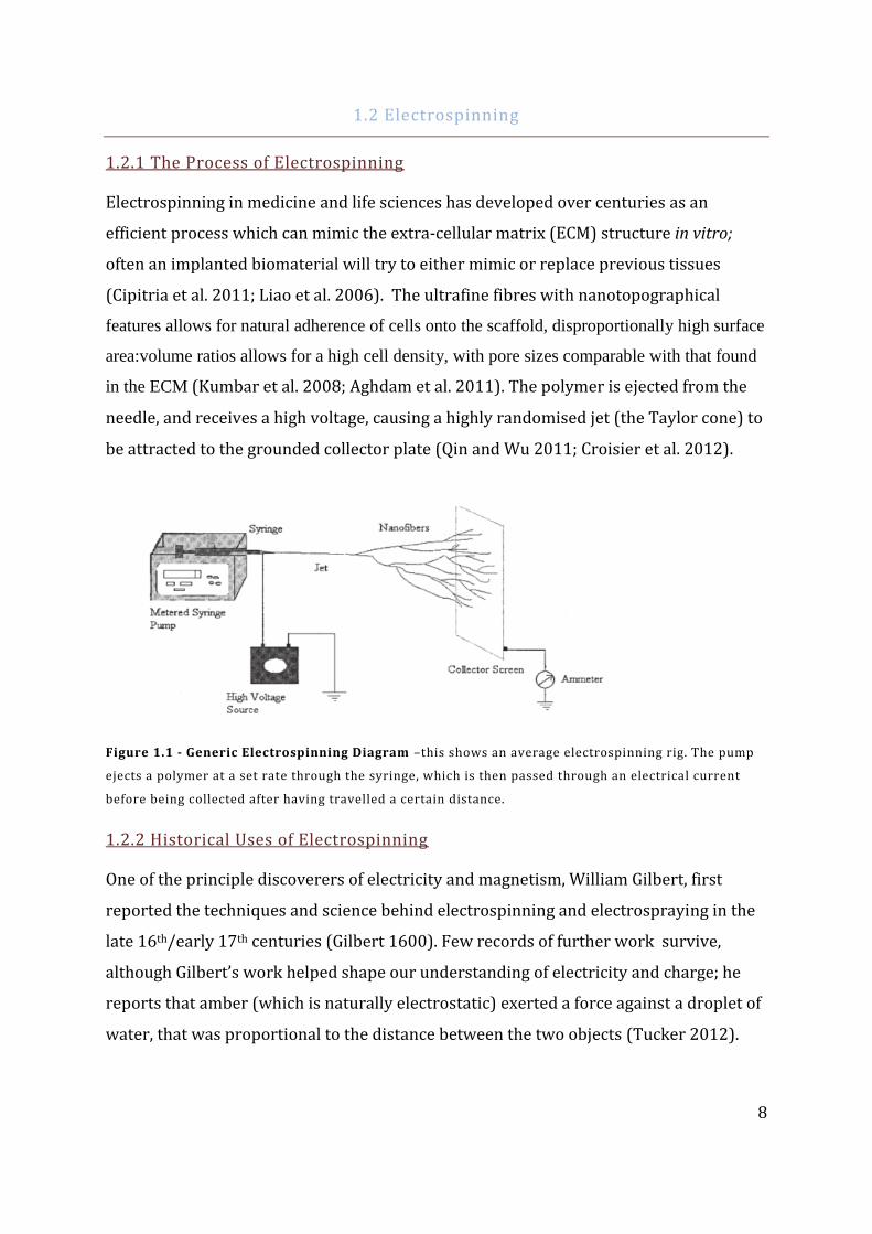
1.2 Electrospinning
1.2.1 The Process of Electrospinning
Electrospinning in medicine and life sciences has developed over centuries as an
efficient process which can mimic the extra-cellular matrix (ECM) structure in vitro;
often an implanted biomaterial will try to either mimic or replace previous tissues
(Cipitria et al. 2011; Liao et al. 2006). The ultrafine fibres with nanotopographical
features allows for natural adherence of cells onto the scaffold, disproportionally high surface
area:volume ratios allows for a high cell density, with pore sizes comparable with that found
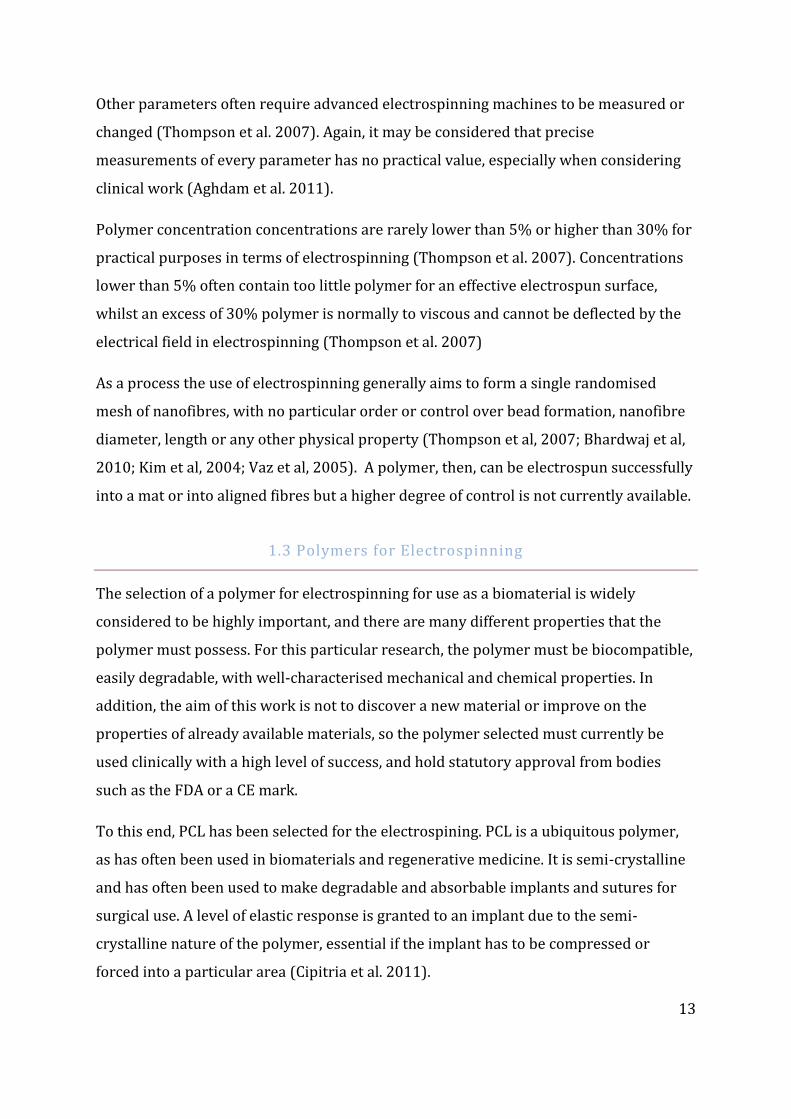
in the ECM (Kumbar et al. 2008; Aghdam et al. 2011). The polymer is ejected from the
needle, and receives a high voltage, causing a highly randomised jet (the Taylor cone) to
be attracted to the grounded collector plate (Qin and Wu 2011; Croisier et al. 2012).
Figure 1.1 - Generic Electrospinning Diagram –this shows an average electrospinning rig. The pump
ejects a polymer at a set rate through the syringe, which is then passed through an electrical current
before being collected after having travelled a certain distance.
1.2.2 Historical Uses of Electrospinning
One of the principle discoverers of electricity and magnetism, William Gilbert, first
reported the techniques and science behind electrospinning and electrospraying in the
late 16th/early 17th centuries (Gilbert 1600). Few records of further work survive,
although Gilbert’s work helped shape our understanding of electricity and charge; he
reports that amber (which is naturally electrostatic) exerted a force against a droplet of
water, that was proportional to the distance between the two objects (Tucker 2012).
9
Later, the prodigious scientist Robert Hooke, theorised that the “cell” structures he had
discovered in biological entities could be replicated by a ductile “glutinous composition”
(Tucker 2012). Further work on this topic was reported at what would later become the
University of Manchester; the researchers’ stated aims being to discover a ductile and
malleable organic substance to be drawn into fibres for manufacturing; nitrocellulose
(fulfilling the requirements) was discovered by accident within a decade (The
Manchester Guardian 1840; Tucker 2012). Although the number of uses, papers and
patents involving electrospinning has increased significantly since the turn of the 21st
century, the first recorded mention of electrospinning as a technique was in 1901, with
further work performed in one of the last German-USSR collaborations before their
conflict in the Second World War, the end result being a successful electrospinning
process in 1938 (Tucker 2012) .
Continuing throughout and beyond the Second World War, and doubtless spurred on by
novel research in what would eventually become the first synthetic biomaterial (PLGA),
electrospinning was repeatedly suggested as a technique which would vilify Hooke’s
suggestion of a replaceable cell structure (Tucker 2012). Codified mathematical
modelling into the fluid flow was set by Geoffrey Taylor, for whom the Taylor cone in
electrospinning was named. It was not until the 1990s that the nanotechnological
aspects of electrospinning were promoted, with the name of electrospinning entering
(relatively) common parlance in scientific circles (Cooley 1902; Kumbar et al. 2008; Qin
and Wu 2011; Cipitria et al. 2011; Tucker 2012). After several years and some
convoluted research, it was shown that there was definite promise for electrospinning
as a ‘novel’ technique for tissue engineering; a field that was at the time captivating the
imaginations of the Press, public and scientists as a whole, mostly with regards to
famous mainstream media publications such as ‘Vacanti’s Ear’ (Li et al. 2002; Matthews
2002) As explained above, the similarity of the electrospun fibres to collagen in the ECM
allowed for a level of biomimicry that stimulated research into skin, vessels, bone,
cartilage and neural areas of regeneration (Hutmacher and Cool 2007). Since the mid-
1990s, research into electrospinning has expanded exponentially; literature searches
show tens of thousands of papers within the last 15 years. For reasons of brevity and
readability, only key review and research papers from recent years will be included
here.
10
Electrospinning was not, however the only nanomesh/nanofibre construction technique
present at the time; there was considerable research into self-assembly and phase
separation – both of which had already shown some successes with regards to in vitro
testing (Cipitria et al. 2011). What set electrospinning apart was the natural formulation
of a high surface:volume area, which was useful for both cells and drug delivery
processes, and a level of naturally variable porosity, essential for mass transport and
macromolecular exchange (Szentivanyi et al. 2011; Vaz et al. 2005; Bianco et al. 2011;
Baati et al. 2012; Deitzel et al. 2001). Another advantage is allowing a co-
electrospinning of various agents, both natural and synthetic. Previous concepts that
have been suggested include the addition of core-sheath nanofibres, which would allow
for a phase transition effect for electrospinning (Luo et al. 2012).
At a glance, one can see a relatively common reporting in papers of this conjoined
technique; PLGA co-spun with PCL, gelatine and collagen, whilst PCL has been found
with all of the above, and Ca-P ceramics, further showing the flexibility of the technique
(Cipitria et al. 2011; K. Kim et al. 2004; Dahlin, Kasper, and Mikos 2011; Subbiah et al.
2005).
1.2.3 Electrospinning Parameters
Analysis of the literature shows several general and widely agreed upon characteristics
of electrospinning; these which often act as constraints for the electrospinning process.
(Thompson et al. 2007; K. Kim et al. 2003). The most fundamental issue with
electrospinning is the low turnover and volume production that can occur (low rates at
approximately 2 kg to higher of 30 kg have been reported); a significantly lower mass
when compared with other materials (Fang et al. 2010). Production values are often
limited on the basis of lower density for most electrospin polymers and therefore low
weight of the polymers, when compared with other materials such as metals or
ceramics (Rnjak-Kovacina and Weiss 2011; Vaquette and Cooper-White 2011).
Secondly, processing control is limited by a reliance on uncontrolled variables during
fibre deposition, often caused by the dynamic interactions in the polymer jet
(Thompson et al. 2007). This can lead to bead formation, and investigations into
limiting such interactions have often proved to be inconclusive (Thompson et al. 2007;
Yarin and Zussman 2004).
11
For example, in work with electrospinning hyaluronic acid ,it was found that increasing
air-flow around the polymer jet lowered bead formation and increased the percentage
of nanofibres that were spun (Wang et al. 2005). Other investigations have suggested
that low surface tension is the primary case of bead formation, and that by controlling
the solution concentration and adding ionic salts, the effect of bead formation can be
reduced or eliminated (Y. Liu et al. 2008). During cell seeding experiments, it was found
that bead artefact formation occasionally assisted in cell culture; it was hypothesised
that the beads allowed for a larger surface area for cell attachment (Deitzel et al. 2001;
Wang et al. 2005).
Fibre diameter ranges are often highly unpredictable at both a given location and across
the electrospun mesh as a whole (Thompson et al. 2007). One paper reports wide
variations in dry fibre diameter; from between 1.15 μm and 6.65 μm (Fridrikh et al.
2003). This variation can hinder detailed characterisation of an electrospun scaffold;
changes in fibre diameter after sterilisation could be absolute (that is, a certain value of
diameter is gained or loss due to chemical changes) or it could be dependent on the
original diameter of the fibre (a percentage change which could be an increase due to
swelling, or decrease due to chemical scission) (Thompson et al. 2007; Bhardwaj and
Kundu 2010; Subbiah et al. 2005). Polymer solution rheology is often dependent on the
complicated interactions between the polymer and the solvent (Dahlin, Kasper, and
Mikos 2011; Thompson et al. 2007).
Although well characterised, it is important to note that the interactions between the
chemicals and the physical machinery in electrospinning can limit the ease of formation
of patterning; this can then limit the level of cell attachment which is possible (Fatih-
Canbolat et al. 2011; Schenke-Layland et al. 2011; Thompson et al. 2007). Whilst
randomly formed fibrous mats provide a weak level of biomimicry which can assist in
cell proliferation, this work will focus on connective tissues, requiring aligned fibres
(Kumbar et al. 2008; Skotak et al. 2011; Fatih-Canbolat et al. 2011).

12
Table 1.1 Problems Facing Electrospinning
Problem Effect Comment Solution
Low turnover
(compared with
other material
techniques)
Must repeat
manufacturing
several times
Could lead to
inconsistencies in
the final product
Larger-scale
electrospinning
machines, effective
use of samples
Undefined variables
(especially surface
tension)
Uneven fibre
distribution, bead
formation
Final product may
have varied surface
properties
Increase air-flow to
raise surface
tension
Fibre diameter Uneven fibre size
and distribution,
variable mechanical
properties
Final product could
have an overly
complex surface,
unneeded when
aligned fibres are
required
Controlled chamber
environment, small
needle-collector
distance
As with all physical manufacturing, there are some input parameters that are often used
to provide a basis for electrospinning. Again, as above, there are several different
standards of parameters, but thirteen stand out across many papers. These are
volumetric charge density, initial elongation viscosity, distance from nozzle to collector,
solvent vapour pressure, initial polymer concentration, density, surface tension
(between the polymer/solvent and air), electrical potential, relaxation time, humidity of
solvent vapour in air, perturbation frequency, jet radius (at the initial, intermediate and
final timepoints) (Thompson et al. 2007; K. Kim et al. 2003; Ekaputra et al. 2011;
Bhardwaj and Kundu 2010; Rnjak-Kovacina and Weiss 2011; Sundararaghavan and
Burdick 2011; Cipitria et al. 2011). These parameters are sometimes reported,
sometimes changed or sometimes ignored, depending on the level of detail of the
investigation, and the importance that electrospinning has been given. There are
reasonable limitations to the amount of alteration that each parameter can be subjected
to: polymer concentration, electric charge and the end-to-end distance between the
nozzle and the collector comprise three parameters that could be simply changed.
13
Other parameters often require advanced electrospinning machines to be measured or
changed (Thompson et al. 2007). Again, it may be considered that precise
measurements of every parameter has no practical value, especially when considering
clinical work (Aghdam et al. 2011).
Polymer concentration concentrations are rarely lower than 5% or higher than 30% for
practical purposes in terms of electrospinning (Thompson et al. 2007). Concentrations
lower than 5% often contain too little polymer for an effective electrospun surface,
whilst an excess of 30% polymer is normally to viscous and cannot be deflected by the
electrical field in electrospinning (Thompson et al. 2007)
As a process the use of electrospinning generally aims to form a single randomised
mesh of nanofibres, with no particular order or control over bead formation, nanofibre
diameter, length or any other physical property (Thompson et al, 2007; Bhardwaj et al,
2010; Kim et al, 2004; Vaz et al, 2005). A polymer, then, can be electrospun successfully
into a mat or into aligned fibres but a higher degree of control is not currently available.
1.3 Polymers for Electrospinning
The selection of a polymer for electrospinning for use as a biomaterial is widely
considered to be highly important, and there are many different properties that the
polymer must possess. For this particular research, the polymer must be biocompatible,
easily degradable, with well-characterised mechanical and chemical properties. In
addition, the aim of this work is not to discover a new material or improve on the
properties of already available materials, so the polymer selected must currently be
used clinically with a high level of success, and hold statutory approval from bodies
such as the FDA or a CE mark.
To this end, PCL has been selected for the electrospining. PCL is a ubiquitous polymer,
as has often been used in biomaterials and regenerative medicine. It is semi-crystalline
and has often been used to make degradable and absorbable implants and sutures for
surgical use. A level of elastic response is granted to an implant due to the semi-
crystalline nature of the polymer, essential if the implant has to be compressed or
forced into a particular area (Cipitria et al. 2011).
14
PCL is a suitable polymer for electrospinning, and with the correct concentration of
solution, can easily allow for directed and aligned nanofibre construction, through a
process of chain entanglements (Qin and Wu 2011). It has been noted several times that
an essential parameter in the electrospinning process of PCL is in fact the choice and use
of the solvent. For high levels of biocompatibility, suitably solvent nature and low
temperature and ease of volatilisation, 1,1,1,3,3,3hexafluro-2-propanol (HFIP) has often
been cited as the correct choice of solvent for electrospinning PCL; despite the highly
toxic nature and carcinogenic nature of HFIP, volatilisation can rapidly occur, leaving
HFIP a safe polymer to use (Szentivanyi et al. 2011; Subbiah et al. 2005; Liao et al. 2006;
Kidoaki, Kwon, and Matsuda 2005; Fatih-Canbolat et al. 2011). Cell viability has been
suggested to be higher with HFIP as the solvent than any other; this indicates a
preference for HFIP when cell work is to be carried out, despite some solvents showing
a better overall profile of results from electrospinning (Fatih-Canbolat et al. 2011;
Szentivanyi et al. 2011; S. J. Kim et al. 2010; Cipitria et al. 2011; Bhardwaj and Kundu
2010).
With the increase into research of electrospun PCL, there has been a significant increase
in the number of applications in the regenerative medical field. Having received FDA
approval for many years already as sutures, PCL products are often seen as more
attractive when looking into clinical trials for different areas. If a commonly found
preparation of PCL is used for the new biomaterial product, then this can often present
a slightly shorter route through pre-clinical testing, both in vitro and in vivo (Sun et al.
2010). Most modern uses now require a coating or post-manufacture
modification/processing for added effect, often focusing on adsorption of proteins and
other biomolecules onto the surface (Cipitria et al. 2011). Studies have shown the use of
collagen, laminin, heparin, and gelatine, amongst others, to be successful in allowing a
good level of surface interaction between the implant and native biochemical factors in
situ (Liao et al. 2006; Dahlin, Kasper, and Mikos 2011; Ma, Mao, and Gao 2007). Coatings
can also have a direct effect on the growth of the tissues around the implant; neurite
growth after laminin deposition has been cited as a notable effect (Ji et al. 2013; Cipitria
et al. 2011; Sundararaghavan and Burdick 2011; Sun et al. 2010).
15
It is not always, however, practical to coat an implant before testing; depending on the
deposition technique used, the natural porosity of PCL (a good characteristic of the
polymer) may be lost due to a large sized coating for example (Liao et al. 2006; Jha et al.
2011; Vaz et al. 2005; Kumbar et al. 2008).
When an electrospun PCL-derived implant is needed for tissues with an inherent
directional order to them (e.g. tendons, ligaments and nerves), aligned electrospinning
can be used to form electrospun fibres in a certain direction (Yang et al. 2005). Various
techniques have been designed to accomplish this, often the collecting mandrel is
rotated at a high enough speed (the minimum has been reported to be anywhere in
between the region of 500 and 1000 RPM) to cause deposition of the fibres in an aligned
pattern (Kidoaki, Kwon, and Matsuda 2005; Fatih-Canbolat et al. 2011; Seretoudi,
Bikiaris, and Panayiotou 2002).
1.3.1 Characterisation Techniques for PCL Analysis
With all the possible variables in the electrospinning process of PCL, it is important that
the final product is suitably characterised, so that the specific properties of that material
can be factored in to any analysis, especially if the material will have a clinical use (Vaz
et al. 2005; Lasprilla et al. 2010).
Often, the most important characterisation factor that a material might have is its
resistance to mechanical load. A material will be subjected to mechanical forces during
the implantation surgery and during tissue growth (Cottam et al. 2009; Liao et al. 2006).
PCL implants must resist any load and not lose their function; uniaxial tensile testing is
often employed to find the average maximum loads that scaffolds can endure. Results
from this testing will often take the form of a stress-strain curve, from which Young’s
modulus (E), yield stress (σs), yield strain (ε), fracture deformation stress (σf), fracture
deformation strain (εf) can be obtained.
For high load applications involving large scaffolds (skeletal applications in particular),
an energy release per volume through failure (the integration of a stress-strain curve)
may be helpful (Cipitria et al. 2011; Levenberg et al. 2005). The standard testing
16
technique does have some drawbacks however. With regards to clinical use one of the
chief criticisms that could be levelled at traditional uniaxial tensile testing for PCL is the
use of standard polymeric testing conditions (Seretoudi, Bikiaris, and Panayiotou 2002;
Qin and Wu 2011).
50% humidity and room temperature (taken as between 23-25°C) as standard testing
conditions do allow for relatively easy repeatability, but fail to replicate physiological
conditions to which any biomaterial would be subjected. Proposed solutions to this
include raising the testing environment to 37°C (this would cause an increase in PCL
stretching) or conditioning the PCL in a standardised culture medium before tensile
testing. (Cipitria et al. 2011; Seretoudi, Bikiaris, and Panayiotou 2002). The selections of
media for conditioning a scaffold could also be specific to the eventual clinical role of the
scaffold, with the conditioning being used under a similar rationale as conditioning for
cell seeding – a more biomimetic environment allows for results that can better model
physiological conditions, so can be referred to easier when looking at in vivo and in vitro
testing.
Chemical composition is a significant factor in the behaviour of any material, and
directly links into almost all other properties that a material might have (Hemmrich et
al. 2005; Masson et al. 1997; Sabir, Xu, and Li 2009). An effective but occasionally
destructive method of testing chemical composition is to use ATR Fourier Transform
Infrared Spectroscopy (FT-IR), which can detect the molecular weight of a polymer
sample, as well as show if any additives to the electrospinning process have being
incorporated into the scaffold (Cipitria et al. 2011). It has been shown that different
processes techniques and inclusion of additives to a sample can alter the chemical
structure and therefor the sample’s behaviour; residual ethanol from lab sterilisation
and cleaning, for example, can lead to a change in behaviour of PCL and could also affect
any cells that were being seeded onto the scaffold. (Vaquette and Cooper-White 2011;
Yun et al. 2004; Cipitria et al. 2011). FT-IR requires the use of an imaging crystal to be
placed close to a sample, with a depth of analysis that allows for the imaging of the
whole electrospun fibre, not just the surface, as is common with other classes of
materials (Cipitria et al. 2011). However, the requirement for such close proximity of
the imaging crystal to the fibres often crushes them, rending the sample destroyed
17
(Aghdam et al. 2011). Penetration of the FT-IR evanescent wave is approximately 1 μm,
which is sufficient to measure the electrospun mats (Aghdam et al. 2011)
The percentage or level of crystallinity of PCL will greatly affect the tensile strength of
any scaffold (Qin and Wu 2011). Analysis of this is done by means of differential
scanning calorimetry (DSC), where a sample is heated and the fluctuation in thermal
energy through the sample is graphed (Qin and Wu 2011; Bianco et al. 2011).
The crystallinity of electrospun PCL can be influenced by the presence of residual
solvent, with a higher solvent boiling point being proportional to a higher glass
transition temperature for PCL (Qin and Wu 2011).
As seen below, radiation can have the effect of either increasing or decreasing
crystallinity of a sample, due to chain scission and free radical reactions (Masson et al.
1997; Cottam et al. 2009). Stretching the polymer after it has been electrospun, as could
occur during collecting or testing, can also increase crystallinity (Cipitria et al. 2011). As
it is possible to control the percentage level of crystallinity (up until a point), the
increased mechanical properties that occur with increased crystallinity can be tailored
to each specific application.
The hydrophobic or hydrophilic properties of the electrospun PCL can be inferred by
measuring the contact angle of a droplet of water on the surface – a higher angle shows
a higher level of hydrophobicity. Reports for PCL vary; films appear to have a lower
contact angle than electrospun nanofibre meshes, with values from 105° to 129° being
suggested (Cipitria et al. 2011; Ekaputra et al. 2011). However rough the consensus,
PCL is clearly not a wildly hydrophilic polymer; the creation of a PCL composite with
gelatine or collagen greatly increases the hydrophilicity – in large concentrations, the
contact drops to approximately 0° (Liao et al. 2006; Sabir, Xu, and Li 2009; Pham,
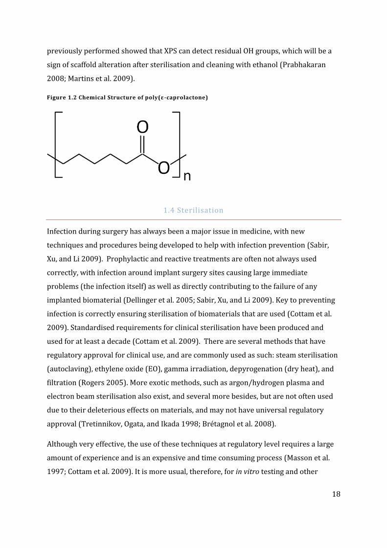
Sharma, and Mikos 2006; Cipitria et al. 2011). Chemically, PCL is a relatively simple
structure, comprising sigma and pi bonds between C, H and O; this can be seen in Figure
1.2. This structure makes PCL a good candidate for analysis by x-ray photoelectron
spectroscopy (XPS); the small size of samples commonly present leads however, to
semi-quantitative analysis, often done to confirm or deny whether a new substrate was
included or excluded during the electrospinning process (Cipitria et al. 2011). Analysis
18
previously performed showed that XPS can detect residual OH groups, which will be a
sign of scaffold alteration after sterilisation and cleaning with ethanol (Prabhakaran
2008; Martins et al. 2009).
Figure 1.2 Chemical Structure of poly(ε-caprolactone)
1.4 Sterilisation
Infection during surgery has always been a major issue in medicine, with new
techniques and procedures being developed to help with infection prevention (Sabir,
Xu, and Li 2009). Prophylactic and reactive treatments are often not always used
correctly, with infection around implant surgery sites causing large immediate
problems (the infection itself) as well as directly contributing to the failure of any
implanted biomaterial (Dellinger et al. 2005; Sabir, Xu, and Li 2009). Key to preventing
infection is correctly ensuring sterilisation of biomaterials that are used (Cottam et al.
2009). Standardised requirements for clinical sterilisation have been produced and
used for at least a decade (Cottam et al. 2009). There are several methods that have
regulatory approval for clinical use, and are commonly used as such: steam sterilisation
(autoclaving), ethylene oxide (EO), gamma irradiation, depyrogenation (dry heat), and
filtration (Rogers 2005). More exotic methods, such as argon/hydrogen plasma and
electron beam sterilisation also exist, and several more besides, but are not often used
due to their deleterious effects on materials, and may not have universal regulatory
approval (Tretinnikov, Ogata, and Ikada 1998; Brétagnol et al. 2008).
Although very effective, the use of these techniques at regulatory level requires a large
amount of experience and is an expensive and time consuming process (Masson et al.
1997; Cottam et al. 2009). It is more usual, therefore, for in vitro testing and other
19
laboratory work to be carried out using samples that have been sterilised using ethanol
and/or UV light (Bosworth, Gibb, and Downes 2012; Huang et al. 2003; Pham, Sharma,
and Mikos 2006)Whilst far quicker and easier to use than clinical methods, allowing
more work to be carried out, it means that published results may only be relevant for
samples that have used laboratory-level sterilisation.
As this work will be using PCL, it is important to take the physical and chemical
characteristics of the polymer into consideration when choosing which sterilisation
methods to use. Due to the low melting point of PCL (a bulk sample would be expected
to melt at 60°C, with high surface area:volume designs having a melting point at around
55°C) it is obvious that some of the previously mentioned techniques will not be
suitable (Sun et al. 2010; Rogers 2005).
Procedures involving heat as their primary method for sterilisation (dry heat and
autoclaving) are immediately ruled out, as these often function at over 120°C, which
higher than the melting point of PCL which is 60°C (Rogers 2005). A filtration technique
would only be suitable for sterilising a solution, and is not applicable in this situation.
Plasma and electron beam sterilisation, whilst valid techniques, are comparatively
complicated to use, whilst not being too common; other methods can be equally
effective without over-complicating their use (Brétagnol et al. 2008; Tretinnikov, Ogata,
and Ikada 1998). The remaining two methods suitable for this work, ethylene oxide and
gamma irradiation have a proven track record in biomaterials science, being widely
used and are considered ‘effective’ (Rogers 2005; Gorna and Gogolewski 2003; Narkis
1984; Benson 2002). Key to the work undertaken in this thesis, the technique would
ideally not significantly or appreciably degrade, damage or in some way alter the nature
of the biomaterial, and certainly not to a level where the material function was impacted
(Cottam et al. 2009; Masson et al. 1997; Rogers 2005; Cipitria et al. 2011). There must
also be a level of trust in the technique, backed up by scientific research, that allows for
regulatory and professional approval (Rogers 2005).
20
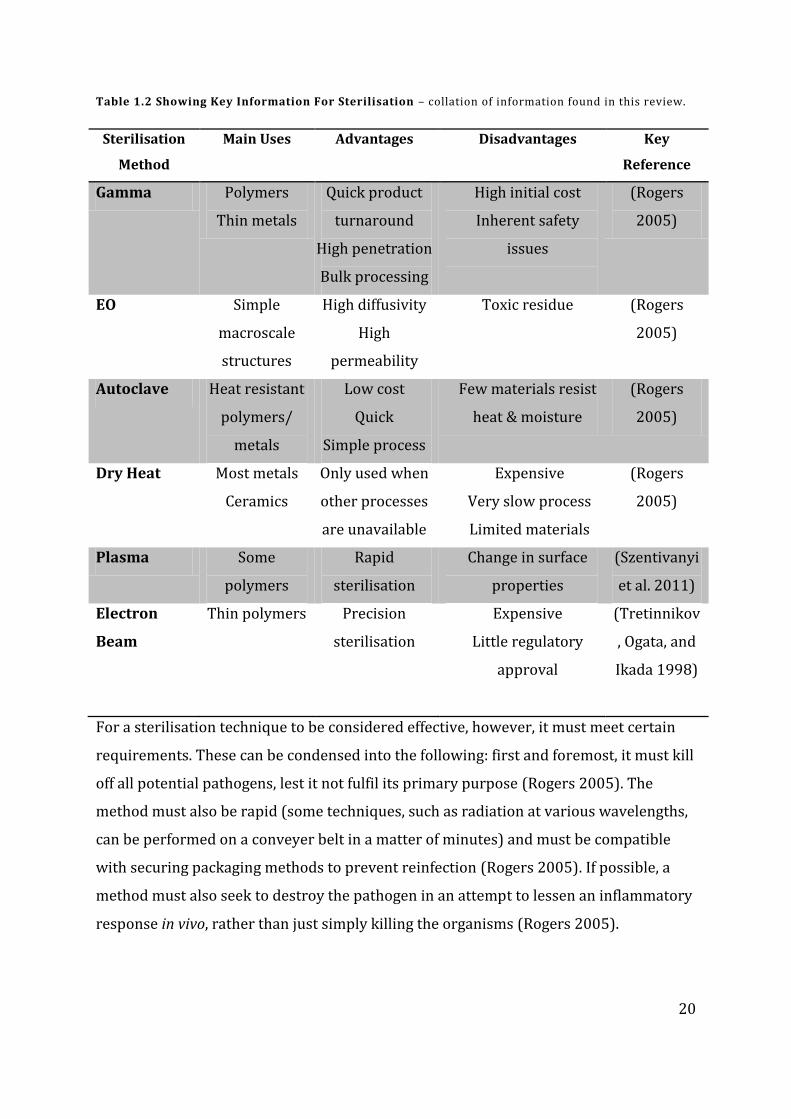
Table 1.2 Showing Key Information For Sterilisation – collation of information found in this review.
Sterilisation
Method
Main Uses Advantages Disadvantages Key
Reference
Gamma Polymers
Thin metals
Quick product
turnaround
High penetration
Bulk processing
High initial cost
Inherent safety
issues
(Rogers
2005)
EO Simple
macroscale
structures
High diffusivity
High
permeability
Toxic residue (Rogers
2005)
Autoclave Heat resistant
polymers/
metals
Low cost
Quick
Simple process
Few materials resist
heat & moisture
(Rogers
2005)
Dry Heat Most metals
Ceramics
Only used when
other processes
are unavailable
Expensive
Very slow process
Limited materials
(Rogers
2005)
Plasma Some
polymers
Rapid
sterilisation
Change in surface
properties
(Szentivanyi
et al. 2011)
Electron
Beam
Thin polymers Precision
sterilisation
Expensive
Little regulatory
approval
(Tretinnikov
, Ogata, and
Ikada 1998)
For a sterilisation technique to be considered effective, however, it must meet certain
requirements. These can be condensed into the following: first and foremost, it must kill
off all potential pathogens, lest it not fulfil its primary purpose (Rogers 2005). The
method must also be rapid (some techniques, such as radiation at various wavelengths,
can be performed on a conveyer belt in a matter of minutes) and must be compatible
with securing packaging methods to prevent reinfection (Rogers 2005). If possible, a
method must also seek to destroy the pathogen in an attempt to lessen an inflammatory
response in vivo, rather than just simply killing the organisms (Rogers 2005).
21
Techniques which aim to kill or disable organisms may not necessarily be synonymous
with sterilisation, as a material may only be considered sterile if, after statistically
significant sampling of products, it is reasonable to assume the material is 100% free of
active organisms (Rogers 2005). Laboratory based techniques, such as
washing/immersing in ethanol are more properly considered cleaning techniques, as
there is not a high degree of certainty regarding 100% killing of organisms (Rogers
2005). Resistance to sterilisation is an issue that has often been noted, and techniques
are always reviewed to prevent for the formation of sterilisation-resistant lineages of
microbes (Rogers 2005). Although primarily bacterial resistance to gamma or chemical
sterilisation has caused concern, resistance has been found in fungi, viruses and prions
(Rogers 2005). Thankfully, other techniques can be used or combined in tandem to
ensure adequate elimination of resistant strains; heated moisture methods are often
thought to be the most effective in dealing with resistance to sterilisation (Tretinnikov,
Ogata, and Ikada 1998; Brétagnol et al. 2008; Rogers 2005). Any living pathogens which
remain on the sample after sterilisation form what is termed the “bioburden” of the
sample, and a percentage of the sterilised batches would be tested for bioburden,
primarily to ensure that the sterilisation has worked effectively. Should a statistically
significant number of samples within a batch show an unacceptable level of bioburden,
it is likely that the whole batch would be re-sterilised, and a possible recall of previously
distributed products may even occur. A brief overview of the different types of
sterilisation may be found in Table 1.2, above.
1.4.1 Gamma Irradiation
Gamma radiation is a high frequency (10 EHz) ionising form of radiation, containing a
high level of energy per ejected photon. The small wavelength (10 pm) allows an
extremely high level of penetration by the wave-particle, and the ionisation will easily
disrupt cellular DNA leading to apoptosis and necrosis in mammalian cells. When
artificially generated, the dose and path of the rays can be precisely controlled. This
allows for contrasting uses such as wide-scale imaging of shipping containers at ports,
to highly focused “gamma knives” used in some cancer surgeries. More commonly,
gamma rays can be used to prevent the spoiling of fresh food and for sterilisation of
medical equipment. For hospital sterilisation and other small-scale sterilisation
22
procedures, caesium-137 is used as the isotope in a semi-portable sterilisation unit. For
large scale sterilisation, as well as some chemotherapy application, cobalt-60 is used
(Rogers 2005).
Gamma irradiation for medical-grade sterilisation has found polymer products as its
niche. In terms of commonly used polymers for medical use, only poly(proplyne)(PP)
and poly(tetrafluoroethylene)(PTFE) are considered not to be suitable for gamma
irradiation, due to the amount of degradation to the chemical structure that can occur.
(Rogers 2005). When any polymer is subjected to high energy radiation, such as during
gamma sterilisation, two competing processes occur. Firstly, scission of the chemical
bonds occurs, lowering the mechanical strength and elastic modulus of the polymer,
weakening it overall (Benson 2002; Rogers 2005). Secondly however, polymer
strengthening can occur during high energy bombardment, due to the formation of
radical groups that can lead to cross-linking (Benson 2002; Rogers 2005). This cross-
linking results in a higher level of mechanical properties for the polymer (Rogers 2005;
Benson 2002). Due to the conflicting nature of cross-linking and scission reactions,
predicting the change in mechanical properties after irradiation is notoriously difficult,
and is often determined experimentally (Narkis 1984; Rogers 2005; Masson et al. 1997).
When comparing and contrasting polymer behaviour under sterilisation, it is common
to report the ratio between how often cross-linking and scission occurs (Rogers 2005).
Whilst this may not necessarily determine the exact properties of the altered material, it
has shown to be an effective tool for estimating the changes (Rogers 2005) It is also
important to note that the change in mechanical properties may not always be
undesirable, or that an undesirable change would be to weaken the polymer; depending
on the context, strengthening the polymer may increase the mechanical properties to an
unsuitable level (Brétagnol et al. 2008; Tretinnikov, Ogata, and Ikada 1998). Simple
manufacturing techniques can be used to buffer a minor change in mechanical
properties. Generally, polymers can be protected from small changes by increasing the
cross-linking percentage or increasing the curing temperature , as appropriate for the
material (Rogers 2005). This cannot be considered a perfect solution, however. Such
techniques would only work on a number of polymers.
23
The amount of radiation that is given in each irradiation of a sample (the dose) is tightly
regulated, and follows ISO protocols. Such doses are measured in Greys (Gy), with one
Gy being the absorption of one Joule per kilogram of material. ISO 13409, the accepted
standard for irradiating medical devices, along with ISO 11137 calls for a 25 kGy dose
for each product as a starting level (Rogers 2005; Cottam et al. 2009). Although this
could be excessive or inadequate for some products, a vast array of research into the
remaining pathogens (the measure of bioburden) provided statistical evidence for
promoting 25 kGy as a good starting point; each type of product should, of course, be
checked to ensure that no pathogens remain (Benson 2002; Cottam et al. 2009). For a
device that may need a higher dose than the standard 25 kGy or has unusual properties,
further investigation is performed. Fractional doses of the 25 kGy are given to each
device, and analysis for bioburden can be used to suggest the required level of
irradiation, in accordance with ISO 11137 (Rogers 2005). Due to the high penetration of
gamma radiation, however, it is unusual for any change to the standard protocol to be
needed, in the context of medical devices (Rogers 2005; Cottam et al. 2009).
Damage from irradiation on polymers has been documented, and is often seen as a
drawback to this method (Narkis 1984; Brétagnol et al. 2008). For biomaterials that do
not need their properties to be kept at precise levels, this may not be a problem (Rogers
2005; Benson 2002; Cottam et al. 2009). However, there are many implants that require
that level of precision, and any significant deviation from this could cause clinical and
regulatory issues (Rogers 2005). Drug eluting stents, for example, must release their
drug at a specific rate for a specific amount of time, often with the stent degrading at a
constant rate to allow this to happen, and ensuring a zero-order release (Olbrich et al.
2007; Rogers 2005). Damage from radiation has been shown to alter the
physiochemical properties of several polymers, so in cases where this damage is not
acceptable, alternative sterilisation methods should be used (Benson 2002; Rogers
2005; Cottam et al. 2009; Brétagnol et al. 2008).
In terms of the effects of gamma irradiation on PCL, there is a small amount of literature
available, although this can be conflicting at times. Analysis of PCL films suggests that
radiation has a clear effect on samples in terms of their degradation with regards to
mass (Cottam et al. 2009).

24
Untreated samples would degrade at a slower rate, and showed a more even and
smooth microscopic structure, when compared with samples irradiated at 25 kGy
(Cottam et al. 2009). Qualitative and semi-quantitative changes in physical structure
between irradiated and non-irradiated samples were mirrored with an increase in
tensile stress strength (Cottam et al. 2009). Possible reasons for this centred on an
increase in crystallinity, as measured by DSC analysis (Cottam et al. 2009; Benson
2002). Small changes in crystallinity, and other physiochemical measurements have
often been suggested as having a disproportionate effect on mechanical properties
(Xing, Zha, and Yang 2010; Masson et al. 1997). However, a more recent analysis of
electrospun PCL has shown gamma irradiation to effect a massive loss in mechanical
properties, with 15 kGy (below the ISO standard) being reported as producing a 61%
loss in mechanical strength (Bosworth, Gibb, and Downes 2012).
Unusually, however, there was not a reciprocal loss in maximum elongation as would
perhaps have been expected. (Bosworth, Gibb, and Downes 2012). Although the reasons
for this are not speculated upon in the paper, directional differences in the crosslinking
to scission ratio, brought on by different bonding energies, could explain a change of
this type. Comparable findings were also seen in GPC analysis, showing a reduction in
molecular mass in the samples with the highest degree of irradiation of between 12-
33%, which would again point to gamma radiation causing chain scission effects
(Bosworth, Gibb, and Downes 2012). Further evidence is given when detailed
investigations into GPC show the number average molecular weight (Mn) decreasing
(indicative of scission) but the weight average molecular weight (Mw) increasing
marginally, suggesting that cross-linking is occurring in some areas. (Cottam et al.
2009). Similar occurrences, with similar implications draw, were also reported in
experiments with PCL nanospheres (Masson et al. 1997)
Whilst the physical and mechanical changes in PCL are important, it is essential to
remember that the future aim of most experiments is to head towards a stage where
these scaffolds can be implanted as medical devices. Several papers have reported no
significant changes in cell culture or viability rates after sterilisation (Cottam et al. 2009;
Bosworth, Gibb, and Downes 2012). Gamma irradiation was often compared with
25
ethanol (commonly used for lab sterilisation/cleaning), and flow cytometery results did
not show any significant changes in cell attachment (Cottam et al. 2009).
Although no results have been reported for virgin samples (there is always a need for
sterilisation at some level of a sample), ethanol and gamma irradiated samples both
allow cells to orientate and elongate in the direction of the fibres, suggesting that there
was not any loss in cell guidance (Cottam et al. 2009). Additionally, sample which were
sterilised both by irradiation and ethanol did not show any difference from when the
samples were sterilised individually (Bosworth, Gibb, and Downes 2012).
1.4.2 Ethylene Oxide
Whilst gamma irradiation is perfectly suited to sterilising liquids and thin solids,
autoclaving can rapidly sterilise heat resistant materials, ethylene oxide has found
wide-ranging popularity in hospitals, especially with polymer products (Rogers 2005).
Ethylene oxide is an aromatic ether compound, with little overall charge. It is modestly
reactive, with a very high chemical volatility, ensuring that it is gaseous at easily
accessible temperatures (with a boiling point of ~10°C), increasing its availability
(Rogers 2005).
Sterilisation with EO is a comparatively complex technique after looking at gamma
irradiation, and, whilst highly dangerous to use, there are none of the inherent superior
risks that inevitably come from using radiation (Rogers 2005). Gaseous EO is pumped
into the sterilisation chamber at a reasonably cool temperature of anywhere between
50 – 60°C, which can then penetrate the vast majority of samples; although thick and
complex patterns, like woven mats, are often sterilised with caution (Rogers 2005).
At least one research group has suggested that EO is unable to fully penetrate complex
shapes, ager finding residual microbes on an EO-sterilised product, but not one
sterilised by autoclaving (Yoon et al. 2012).
The temperature used has proven to be an effective one, as most polymers will have
higher melting points (Rogers 2005). It should be observed though, that the large group
of biomaterials that are designed to react at physiological conditions, especially
temperature, would be categorically unsuitable for sterilisation in this manner.
26
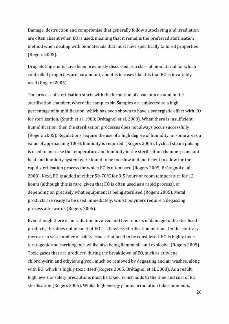
Damage, destruction and compromise that generally follow autoclaving and irradiation
are often absent when EO is used, meaning that it remains the preferred sterilisation
method when dealing with biomaterials that must have specifically tailored properties
(Rogers 2005).
Drug eluting stents have been previously discussed as a class of biomaterial for which
controlled properties are paramount, and it is in cases like this that EO is invariably
used (Rogers 2005).
The process of sterilisation starts with the formation of a vacuum around in the
sterilisation chamber, where the samples sit. Samples are subjected to a high
percentage of humidification, which has been shown to have a synergistic effect with EO
for sterilisation. (Smith et al. 1988; Brétagnol et al. 2008). When there is insufficient
humidification, then the sterilisation processes does not always occur successfully
(Rogers 2005). Regulations require the use of a high degree of humidity, in some areas a
value of approaching 100% humidity is required. (Rogers 2005). Cyclical steam pulsing
is used to increase the temperature and humidity in the sterilisation chamber; constant
heat and humidity system were found to be too slow and inefficient to allow for the
rapid sterilisation process for which EO is often used (Rogers 2005; Brétagnol et al.
2008). Next, EO is added at either 50-70°C for 3-5 hours or room temperature for 12
hours (although this is rare, given that EO is often used as a rapid process), or
depending on precisely what equipment is being sterilised (Rogers 2005). Metal
products are ready to be used immediately, whilst polymers require a degassing
process afterwards (Rogers 2005).
Even though there is no radiation involved and few reports of damage to the sterilised
products, this does not mean that EO is a flawless sterilisation method. On the contrary,
there are a vast number of safety issues that need to be considered. EO is highly toxic,
teratogenic and carcinogenic, whilst also being flammable and explosive (Rogers 2005).
Toxic gases that are produced during the breakdown of EO, such as ethylene
chlorohydrin and ethylene glycol, much be removed by degassing and air washes, along
with EO, which is highly toxic itself (Rogers 2005; Brétagnol et al. 2008). As a result,
high levels of safety precautions must be taken, which adds to the time and cost of EO
sterilisation (Rogers 2005). Whilst high energy gamma irradiation takes moments,
27
products that are to be sterilised using EO often take several days to thoroughly
perform (Brétagnol et al. 2008). Non-metal samples must be further degassed, for a
suggested time of at least 12-24 hours (Rogers 2005).
Despite the added complications that EO can cause, it is a testament to the effectiveness
and many advantages that EO is still used as a preferred method.
The process by which EO sterilises is remarkably similar to a radiation process, leading
EO to be classed as a radiomimetic poison (Rogers 2005). In a similar method to
alkylating antineoplastic agents used in cancer medication, EO attaches an alkyl group
to nitrogen 7 in the purine ring on guanine (Lopes, Oliveira, and Oliveira-Brett 2013;
Kovalenko et al. 2012; Rogers 2005). Using anti-cancer medication such as cysplatin and
temozolomide as examples, it is known that alkylation of double strand DNA (dsDNA)
immediately begins to interfere with the activities of the cells (Kovalenko et al. 2012;
Lopes, Oliveira, and Oliveira-Brett 2013). Condensation of dsDNA soon follows, and cell
replication is disrupted to the point of apoptosis and necrosis (Lopes, Oliveira, and
Oliveira-Brett 2013). Whilst the effectiveness of alkylating antineoplastic agents and
pseudo-alkylating antineoplastic agents on mammalian cells and the organism at whole
has been known for close to a century (mustard gas used in World War I is an example),
there have also been some studies to show that the agents are also effective against
bacterial species (Escalante 2011; Jugg et al. 2013). Since anti-cancer medication targets
rapidly dividing cells, it is reasonable to assume that bacteria and other rapidly
proliferating organisms are targeted in the same way, and killed by alkylation.
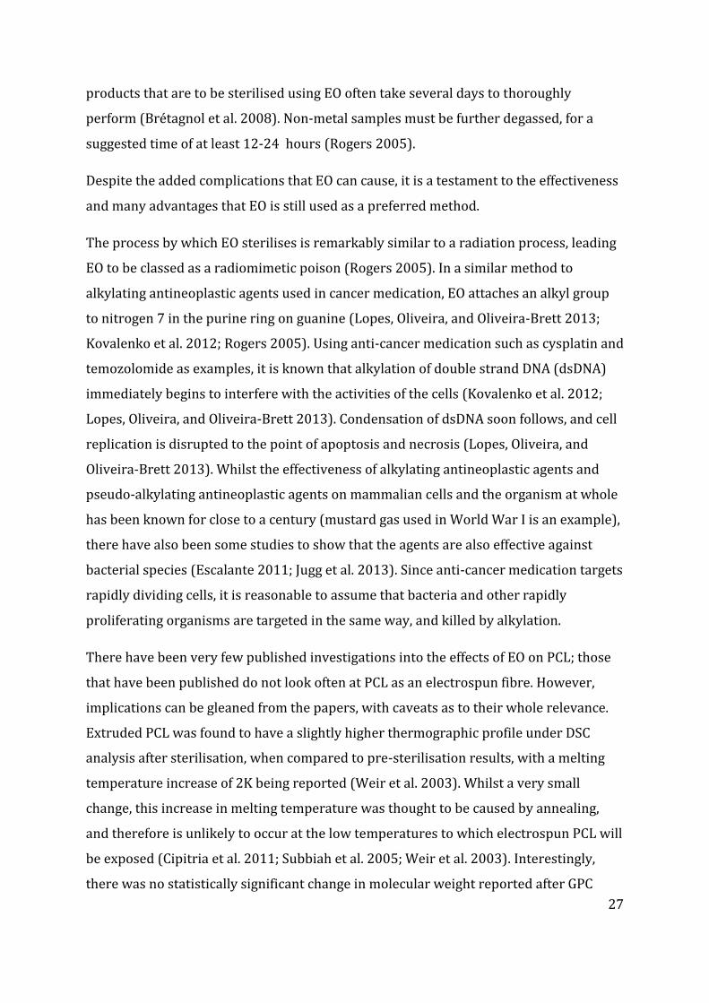
There have been very few published investigations into the effects of EO on PCL; those
that have been published do not look often at PCL as an electrospun fibre. However,
implications can be gleaned from the papers, with caveats as to their whole relevance.
Extruded PCL was found to have a slightly higher thermographic profile under DSC
analysis after sterilisation, when compared to pre-sterilisation results, with a melting
temperature increase of 2K being reported (Weir et al. 2003). Whilst a very small
change, this increase in melting temperature was thought to be caused by annealing,
and therefore is unlikely to occur at the low temperatures to which electrospun PCL will
be exposed (Cipitria et al. 2011; Subbiah et al. 2005; Weir et al. 2003). Interestingly,
there was no statistically significant change in molecular weight reported after GPC

28
analysis, contrasting with the gamma radiation findings (Weir et al. 2003; Cottam et al.
2009). Again divergent with the gamma radiation results, mechanical strength though
tensile testing did not give different results before and after sterilisation; though the
samples tested were highly dissimilar to electrospun PCL (Weir et al. 2003).
Evidently, further investigation and a larger body of research into this area is needed
before conclusive results can be drawn.
Similarly, there is little conclusive evidence on the effects of EO sterilisation on
electrospun PCL with regards to cell culture. Papers published that use EO have shown
there to be little influence on the material (Curran, Tang, and Hunt 2009; See et al.
2012). One paper, using PCL and PCL doped with PLGA suggested that there was a high
degree of cell attachment even when EO sterilisation had occurred; hMSCs were
successfully cultured with no issues reported (Curran, Tang, and Hunt 2009).
All surfaces (pure PCL and PCL doped with up to 30% PLGA) maintained viable levels of
cell attachment, and the sterilisation process did not detrimentally affect cell
proliferation, which remained at the expected level (Curran, Tang, and Hunt 2009). A
hydrogel culture system, exposed to higher levels of EO sterilisation than normal, due to
their thickness, also reported no unusual results in cell culture which could be
attributed to EO sterilisation (See et al. 2012). It is reasonable to assume that, with
regards to cell culture, both EO and gamma radiation have similar effects on cell culture;
the sterilisation method may alter the PCL on a molecular level, but the cell attachment
features (normally the orientated nanofibres) remain mostly unaltered.
29
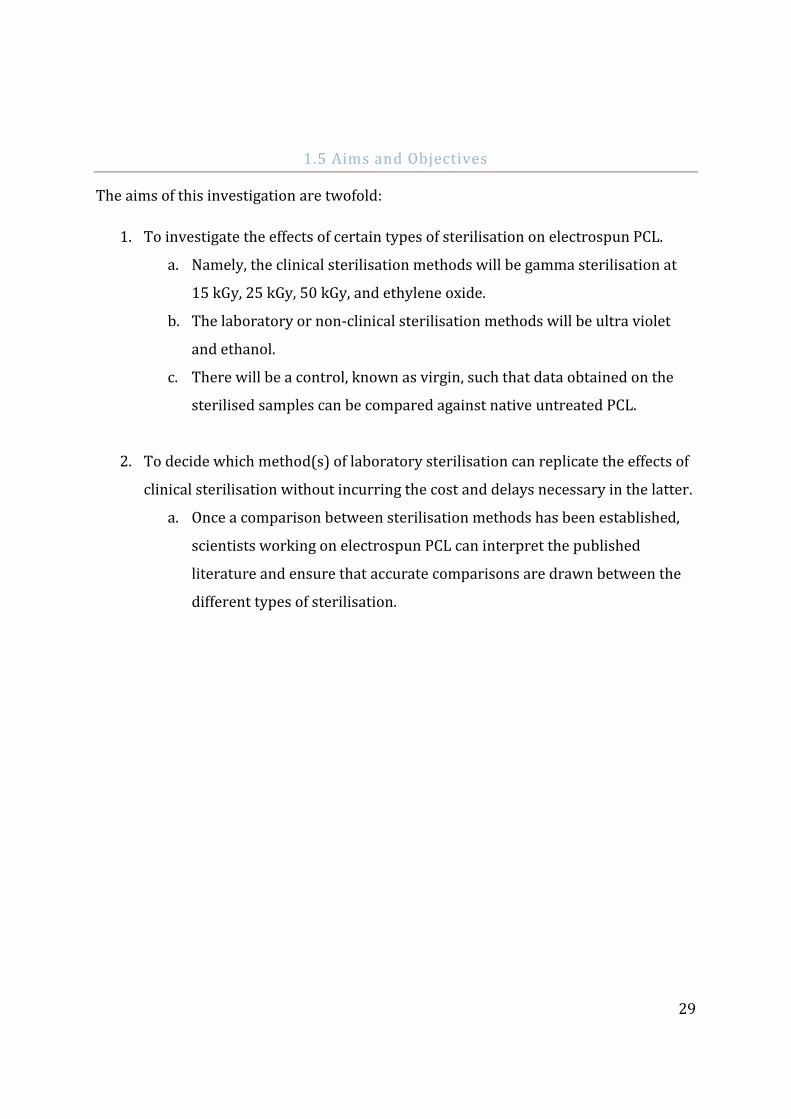
1.5 Aims and Objectives
The aims of this investigation are twofold:
1. To investigate the effects of certain types of sterilisation on electrospun PCL.
a. Namely, the clinical sterilisation methods will be gamma sterilisation at
15 kGy, 25 kGy, 50 kGy, and ethylene oxide.
b. The laboratory or non-clinical sterilisation methods will be ultra violet
and ethanol.
c. There will be a control, known as virgin, such that data obtained on the
sterilised samples can be compared against native untreated PCL.
2. To decide which method(s) of laboratory sterilisation can replicate the effects of
clinical sterilisation without incurring the cost and delays necessary in the latter.
a. Once a comparison between sterilisation methods has been established,
scientists working on electrospun PCL can interpret the published
literature and ensure that accurate comparisons are drawn between the
different types of sterilisation.
30
Chapter 2 : Materials and Methods
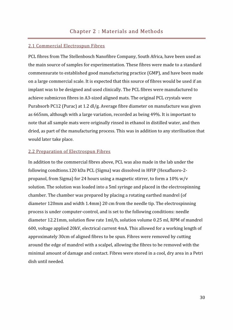
2.1 Commercial Electrospun Fibres
PCL fibres from The Stellenbosch Nanofibre Company, South Africa, have been used as
the main source of samples for experimentation. These fibres were made to a standard
commensurate to established good manufacturing practice (GMP), and have been made
on a large commercial scale. It is expected that this source of fibres would be used if an
implant was to be designed and used clinically. The PCL fibres were manufactured to
achieve submicron fibres in A3-sized aligned mats. The original PCL crystals were
Purabsorb PC12 (Purac) at 1.2 dl/g. Average fibre diameter on manufacture was given
as 665nm, although with a large variation, recorded as being 49%. It is important to
note that all sample mats were originally rinsed in ethanol in distilled water, and then
dried, as part of the manufacturing process. This was in addition to any sterilisation that
would later take place.
2.2 Preparation of Electrospun Fibres
In addition to the commercial fibres above, PCL was also made in the lab under the
following condtions.120 kDa PCL (Sigma) was dissolved in HFIP (Hexafluoro-2-
propanol, from Sigma) for 24 hours using a magnetic stirrer, to form a 10% w/v
solution. The solution was loaded into a 5ml syringe and placed in the electrospinning
chamber. The chamber was prepared by placing a rotating earthed mandrel (of
diameter 120mm and width 1.4mm) 20 cm from the needle tip. The electrospinning
process is under computer-control, and is set to the following conditions: needle
diameter 12.21mm, solution flow rate 1ml/h, solution volume 0.25 ml, RPM of mandrel
600, voltage applied 20kV, electrical current 4mA. This allowed for a working length of
approximately 30cm of aligned fibres to be spun. Fibres were removed by cutting
around the edge of mandrel with a scalpel, allowing the fibres to be removed with the
minimal amount of damage and contact. Fibres were stored in a cool, dry area in a Petri
dish until needed.
31
2.3 Ethanol Sterilisation
Fibres were cut using a scalpel to between 1-2cm (as needed for further use), and fibre
ends that had been potentially damaged during handling were discarded. Each
individual short fibre strip was placed in an Epindorf.
Ethanol solutions were prepared at 50%, 70%, 90% and 100% v:v concentrations.
1.5ml of 50% ethanol was added to each Epindorf in non-sterile conditions, and the
fibres were left for 24 hours. The 50% ethanol was changed for 70% ethanol under
sterile conditions, in a laminar flow hood. The same process was followed for 90% and
100% ethanol solutions. The 100% ethanol was removed under sterile conditions, and
washed with PBS (phosphate buffered saline, pH 7.4, from PAA Labs). 1.5ml of PBS was
added, and left for 25 hours, after which time the PBS was removed and the fibres were
left to air-dry in a sterile environment for at least 48 hours. The fibres were then stored
in sterile conditions to be used in subsequent experiments.
2.4 UV Sterilisation
In a laminar flow hood, a bed of tissue paper was securely taped with autoclave tape to
the floor of the hood. Fibres were flattened without stretching and taped to the tissue
paper, preventing movement due to air flow. Scalpels and forceps were also placed in
the hood, and UV radiation was applied for 30 minutes. The samples were turned over
and taped to the tissue, and irradiated for 30 minutes. The tape, tissue paper and any
damaged sections of fibres were discarded. Fibres were cut according to need under
sterile conditions, and stored in a Petri dish or similar, before being used in subsequent
experiments. It is important to note that “sterile” with regards to EtOH and UV
sterilisation means that a sample has had ethanol or ultraviolet radiation applied
(respectively) and is sterile for the purposes of lab-based experiments. As reported
earlier, such techniques are not acceptable or permitted for medical or clinical use.
32
2.5 Gamma Sterilisation
PCL samples were sent to an external company (Isotron, UK) and sterilised using
gamma radiation at three set doses: 15kGy, 25kGy and 50kGy. 15kGy was chosen as the
standard minimum for most materials, with the two higher doses present to ensure full
sterilisation and penetration of the PCL. For ease of labelling, the doses are hereafter
referred to as 15G, 25G and 50G where appropriate. Fibres were kept in sterile
conditions after returning, and were used in subsequent experiments. Samples of PCL
fibres at each level of irradiation were tested for their residual bioburden.
2.6 Ethylene Oxide Sterilisation
PCL samples were sent to an external company (Isotron, UK) and sterilised using a
standard EO sterilisation protocol. The sterilised samples were given sufficient time to
degass, with the intention that no EO would be present in or on the PCL. Samples were
kept in sterile conditions, and were used in subsequent experiments. It is important to
note that “sterile” with regards to EO and gamma sterilisation means that a sample has
gone through a certified sterilisation procedure with recognised levels of deactivation
or destruction of pathogens.
2.7 Scanning Electron Microscopy
Fibre lengths of 1cm with duplicate repeats were used. Samples were fixed in
glutaraldehyde (if cells were present) and dried using a serial ethanol dilution and
critical point drying with bis(trimethylsilyl)amine (otherwise hexamethyldisilazane,
HDMS). Fibres were mounted onto SEM stubs, and sputter coated with gold. SEM
imaging was performed with a working distance of 8 mm and 5 keV acceleration.
Representative images were taken for analysis. Manual and automated measuring of
fibre length and width was possible. Fibres previously seeded with cells were also
imaged (see Chapter 2 Section 9)
2.8 Diffraction Scanning Calorimetry
Fibre lengths of 1cm, with triplicate repeats were used. Fibre samples were placed and
sealed in aluminium pans, with their weights recorded. Analysis was performed on a
DSC Q100 machine (TA Instruments), with ramp heating at 10°C/minute to an end
temperature of 100°C. Data analysis was performed using the program Universal
33
Analysis 2000 (TA Instruments), with percentage crystallinity being recorded from
curve integration (ΔH = 135.44 J/g).
2.9 Fourier Transform – Infrared Spectroscopy
Fibre lengths of 1cm, with triplicate repeats were used. Samples were prepared and
placed on a Smart Orbit stage (Thermo Scientific) and analysed using a Nicolet 5700
spectrometer (Thermo Scientific). Background spectra were obtained at 32 scans at the
beginning and end of testing. Each fibre was sampled using 16 scans under standard
settings. In addition, spectra of HFIP, ethanol at the given concentrations for ethanol
sterilisation, distilled water and PBS were tested at 32 scans, so that any aberrant peaks
in the PCL spectra could be identified. Data was exported and analysed using Excel
(Microsoft Office).
2.10 Tensile Testing
Fibre lengths of 2cm with five repeats were used. Samples were mounted onto a paper
window, with the ends secured and a clear 1cm of fibre available for testing. The width
was measured using a micrometer and callipers, and the long ends of the window cut, so
only the fibres were loaded. The testing was performed on an Instron machine under
standard and regulated conditions of 23°C and 50% humidity. Samples were allowed to
equilibrate for at least 12 hours before testing. The properties of maximum stress,
Young’s modulus, maximum strain and break displacement could be analysed.
Testing was performed under computer control, with the following conditions:
extension rate of 5mm/minute, full scale load of 100g, grip distance 15mm, and 1N load
cell. Data was exported and analysed using Excel.
2.11 Cell Seeding
L929 mouse fibroblasts (Sigma Aldrich) were cultured using Dulbecco's Modified Eagle
Medium (DMEM)(Invitrogen), modified by the addition of 2mM l-glutamine and 10%
Foetal Bovine Serum (FBS). The fibroblasts were seeded onto sterilised PCL samples
secured to CellCrown Scaffdex (Sigma Aldrich) at a density of 50,000 cells/cm2.
Scaffdexes were placed on ultra-low attachment 24-well cell culture plates (Costar).
Cells were incubated at 37°C and ppCO2 5%.
34
An Alamar blue assay was utilised in order to assess cell metabolic activity on the
scaffolds. 5 mg of Resazurin sodium salt (Sigma) was dissolved in 40 ml of PBS and
filter-sterilised to make the Alamar blue solution. The solution was stored in the dark at
4 ºC when not in use. Each PCL sterilisation condition was repeated in quadruplicate, at
1, 3 and 7 days. Cells were also seeded onto the cell plate, without a scaffold, as a
control. A plate reader (Origin?) was used to analyse the colour change caused by the
degradation of the Alamar blue due to the metabolic rate of the cells. Data from this was
exported and analysed using Excel.
Samples were dehydrated at 1, 3 and 7 days for SEM imaging. Fixation using 1.5%
gluteraldehyde at 4°C for 30 minutes was performed, and dehydration using an ethanol
series of 50%, 70%, 90% and 100% concentration for 2x3 minutes.
Final dehydration using hexamethyldisilazane (HDMS) took place in a fume hood over
24 hours to ensure HDMS evaporation. Each sample was mounted on an SEM stub, and
sputter-coated with gold, before being imaged.
2.12 Gel Permeation Chromatography
Two samples of 2cm PCL strips per condition (4cm for each of the seven PCL
conditions) were rapidly and fully dissolved in 2ml of tetrahydrofuran (THF)(0.2% w/v,
Fisher) and injected into a GPC system (Applied Chromatography Systems) to
determine the average molecular weight (Mw) of PCL, and to note any changes from the
virgin samples.
All pieces of data obtained were compared to the reference Mw provided by polystyrene.
Due to the low volume of PCL-THF, the solute did not undergo filtration before injection
into the GPC system. Results were calculated using PSS GPC software, with the data
exported and further analysed using Excel.
2.13 Water Contact Angle
Several 2cm strips of PCL for each sterilisation condition were taped to microscope
slides and placed in a contact angle measuring machine (Kruss DSA100) . 10 sets of 5μl
droplets of ionised water were dropped onto the PCL, and their angles measured and
recorded by the Drop Shape Analysis software package. This data was then exported,

35
analysed and graphed in Excel. Photographs were also taken using Drop Shape Analysis,
using the camera already built-in to the measuring device.
36
Chapter 3 : Results
The results reported here were chosen from a large bank of collected results, as they are
the clearest and most representative set of results available. Where applicable,
additional results (or their precursors or successors before/after analysis is performed)
are reported as smaller images below the main data
3.1 Fourier-Transform Infrared Spectroscopy
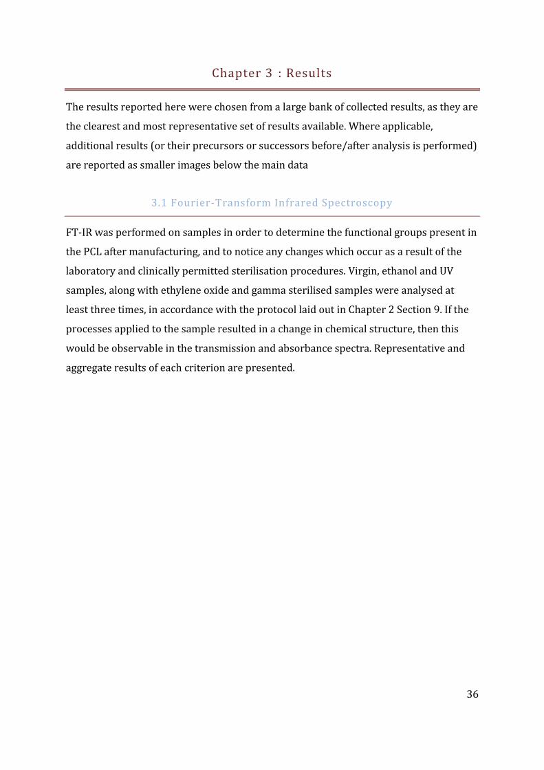
FT-IR was performed on samples in order to determine the functional groups present in
the PCL after manufacturing, and to notice any changes which occur as a result of the
laboratory and clinically permitted sterilisation procedures. Virgin, ethanol and UV
samples, along with ethylene oxide and gamma sterilised samples were analysed at
least three times, in accordance with the protocol laid out in Chapter 2 Section 9. If the
processes applied to the sample resulted in a change in chemical structure, then this
would be observable in the transmission and absorbance spectra. Representative and
aggregate results of each criterion are presented.
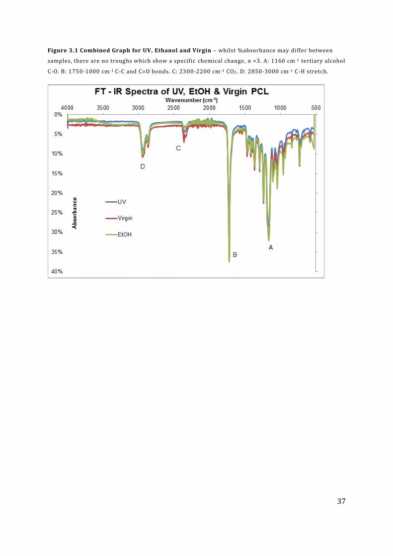
37
Figure 3.1 Combined Graph for UV, Ethanol and Virgin – whilst %absorbance may differ between
samples, there are no troughs which show a specific chemical change, n =3. A: 1160 cm-1 tertiary alcohol
C-O. B: 1750-1000 cm-1 C-C and C=O bonds. C: 2300-2200 cm-1 CO2. D: 2850-3000 cm-1 C-H stretch.
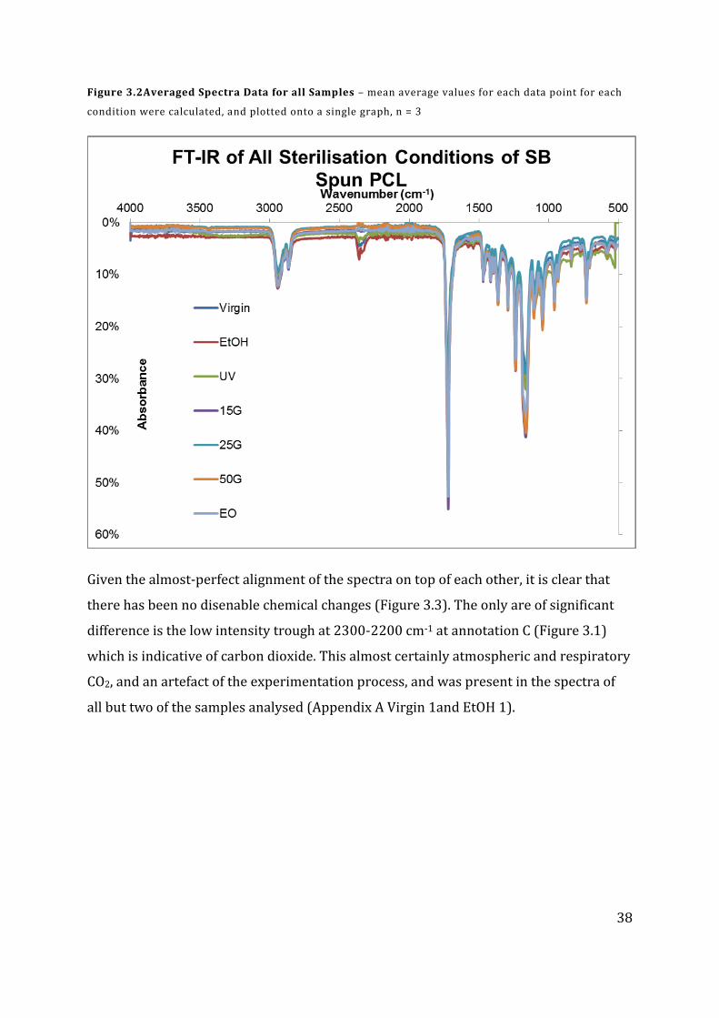
38
Figure 3.2Averaged Spectra Data for all Samples – mean average values for each data point for each
condition were calculated, and plotted onto a single graph, n = 3
Given the almost-perfect alignment of the spectra on top of each other, it is clear that
there has been no disenable chemical changes (Figure 3.3). The only are of significant
difference is the low intensity trough at 2300-2200 cm-1 at annotation C (Figure 3.1)
which is indicative of carbon dioxide. This almost certainly atmospheric and respiratory
CO2, and an artefact of the experimentation process, and was present in the spectra of
all but two of the samples analysed (Appendix A Virgin 1and EtOH 1).
39
3.2 Differential Scanning Calorimetry
DSC analysis was performed on samples of PCL to determining the melting point and
percentage crystallinity of the polymer. The analysis was performed according to the
method set out in Chapter 2 Section 8.
Investigation into the DSC data did not show a statistically significant difference
between the melting points of virgin, ethanol and UV samples (P>0.05) and it can be
seen that any difference between the data is very marginal. The % crystallisation values
are more conclusive, and there is a clear difference between each set of samples, with a
7.2% difference between the ethanol and UV samples. There is a marked difference
between the crystallisation data for the lab sterilisation (virgin, ethanol and UV) and the
clinically acceptable methods (gamma and ethylene oxide), the biggest difference being
26.0% (between UV and 50G).
There was very little observable change in melting point, the average melting point for
all samples was 57.9°C; no sample showed a change greater than ±3°C.
Virgin UV Ethanol
Sample Melting
Point %
Crystallisation Sample
Melting Point
% Crystallisation
Sample Melting
Point %
Crystallisation
1 59.72 38.39 1 60.12 41.20 1 60.72 33.19
2 59.35 34.99 2 59.57 40.46 2 59.71 29.29
3 58.97 37.62 3 59.99 39.07 3 60.35 36.77
Avg 59.35 37.00 Avg 59.89 40.24 Avg 60.26 33.08
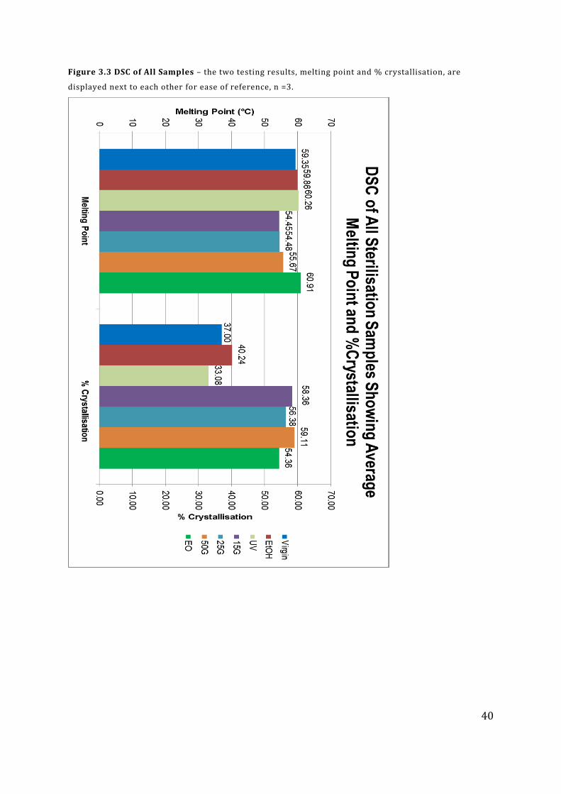
40
Figure 3.3 DSC of All Samples – the two testing results, melting point and % crystallisation, are
displayed next to each other for ease of reference, n =3.
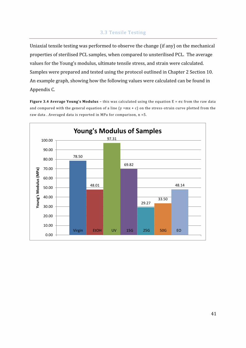
41
3.3 Tensile Testing
Uniaxial tensile testing was performed to observe the change (if any) on the mechanical
properties of sterilised PCL samples, when compared to unsterilised PCL. The average
values for the Young’s modulus, ultimate tensile stress, and strain were calculated.
Samples were prepared and tested using the protocol outlined in Chapter 2 Section 10.
An example graph, showing how the following values were calculated can be found in
Appendix C.
Figure 3.4 Average Young’s Modulus – this was calculated using the equation E = σε from the raw data
and compared with the general equation of a line (y =mx + c) on the stress -strain curve plotted from the
raw data . Averaged data is reported in MPa for comparison, n =5.
78.50
48.01
97.31
69.82
29.27 33.50
48.14
0.00
10.00
20.00
30.00
40.00
50.00
60.00
70.00
80.00
90.00
100.00
Yo
un
g's
Mo
du
lus
(MP
a)
Young's Modulus of Samples
Virgin EtOH UV 15G 25G 50G EO
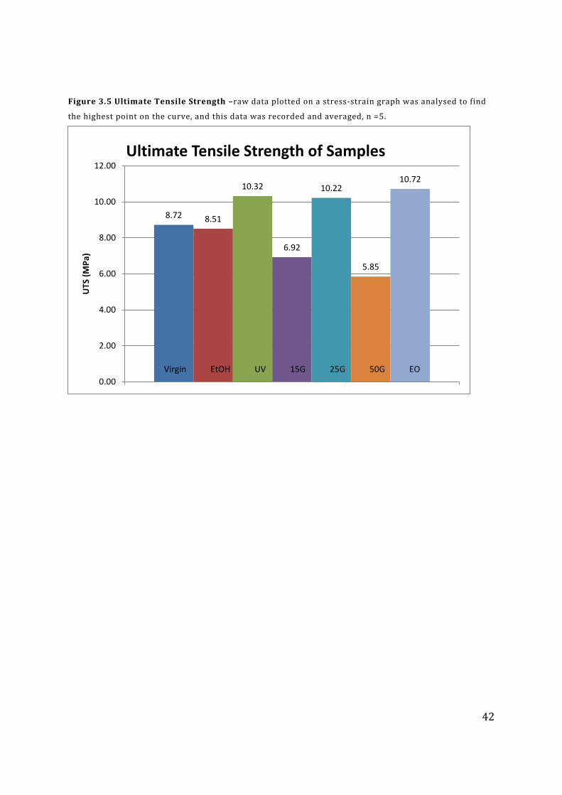
42
Figure 3.5 Ultimate Tensile Strength –raw data plotted on a stress-strain graph was analysed to find
the highest point on the curve, and this data was recorded and averaged, n =5.
8.72 8.51
10.32
6.92
10.22
5.85
10.72
0.00
2.00
4.00
6.00
8.00
10.00
12.00
UTS
(M
Pa)
Ultimate Tensile Strength of Samples
Virgin EtOH UV 15G 25G 50G EO
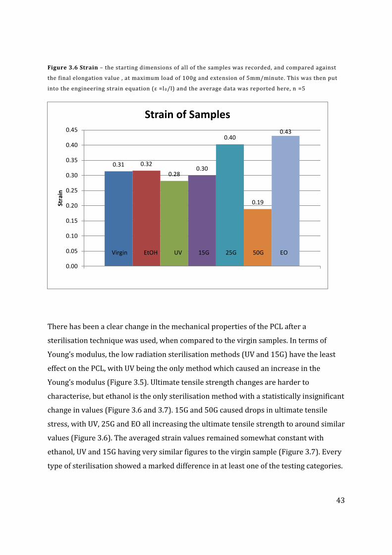
43
Figure 3.6 Strain – the starting dimensions of all of the samples was recorded, and compared against
the final elongation value , at maximum load of 100g and extension of 5mm/minute. This was then put
into the engineering strain equation (ε =l 0/l) and the average data was reported here, n =5
There has been a clear change in the mechanical properties of the PCL after a
sterilisation technique was used, when compared to the virgin samples. In terms of
Young’s modulus, the low radiation sterilisation methods (UV and 15G) have the least
effect on the PCL, with UV being the only method which caused an increase in the
Young’s modulus (Figure 3.5). Ultimate tensile strength changes are harder to
characterise, but ethanol is the only sterilisation method with a statistically insignificant
change in values (Figure 3.6 and 3.7). 15G and 50G caused drops in ultimate tensile
stress, with UV, 25G and EO all increasing the ultimate tensile strength to around similar
values (Figure 3.6). The averaged strain values remained somewhat constant with
ethanol, UV and 15G having very similar figures to the virgin sample (Figure 3.7). Every
type of sterilisation showed a marked difference in at least one of the testing categories.
0.31 0.32
0.28 0.30
0.40
0.19
0.43
0.00
0.05
0.10
0.15
0.20
0.25
0.30
0.35
0.40
0.45
Stra
in
Strain of Samples
Virgin EtOH UV 15G 25G 50G EO
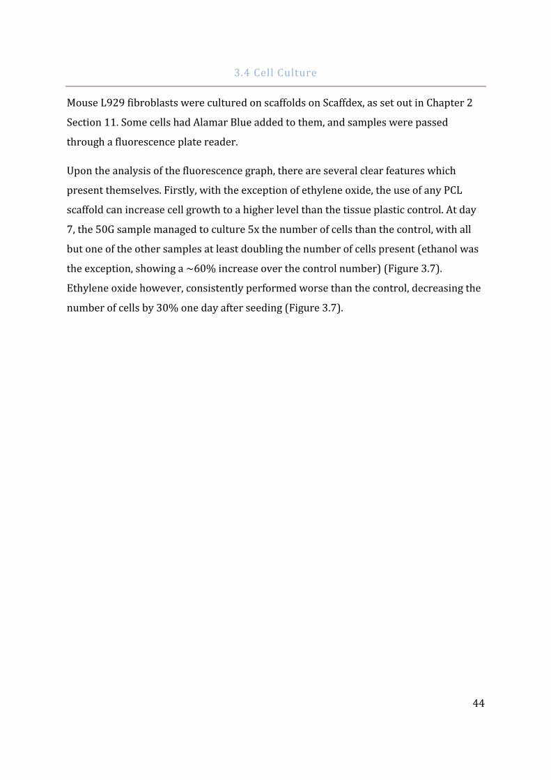
44
3.4 Cell Culture
Mouse L929 fibroblasts were cultured on scaffolds on Scaffdex, as set out in Chapter 2
Section 11. Some cells had Alamar Blue added to them, and samples were passed
through a fluorescence plate reader.
Upon the analysis of the fluorescence graph, there are several clear features which
present themselves. Firstly, with the exception of ethylene oxide, the use of any PCL
scaffold can increase cell growth to a higher level than the tissue plastic control. At day
7, the 50G sample managed to culture 5x the number of cells than the control, with all
but one of the other samples at least doubling the number of cells present (ethanol was
the exception, showing a ~60% increase over the control number) (Figure 3.7).
Ethylene oxide however, consistently performed worse than the control, decreasing the
number of cells by 30% one day after seeding (Figure 3.7).
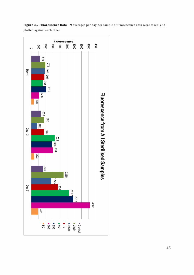
45
Figure 3.7 Fluorescence Data – 9 averages per day per sample of fluorescence data were taken, and
plotted against each other.
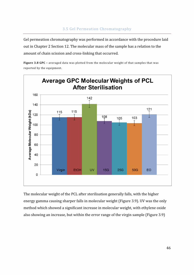
46
3.5 Gel Permeation Chromatography
Gel permeation chromatography was performed in accordance with the procedure laid
out in Chapter 2 Section 12. The molecular mass of the sample has a relation to the
amount of chain scission and cross-linking that occurred.
Figure 3.8 GPC – averaged data was plotted from the molecular weight of that samples that was
reported by the equipment.
The molecular weight of the PCL after sterilisation generally falls, with the higher
energy gamma causing sharper falls in molecular weight (Figure 3.9). UV was the only
method which showed a significant increase in molecular weight, with ethylene oxide
also showing an increase, but within the error range of the virgin sample (Figure 3.9)
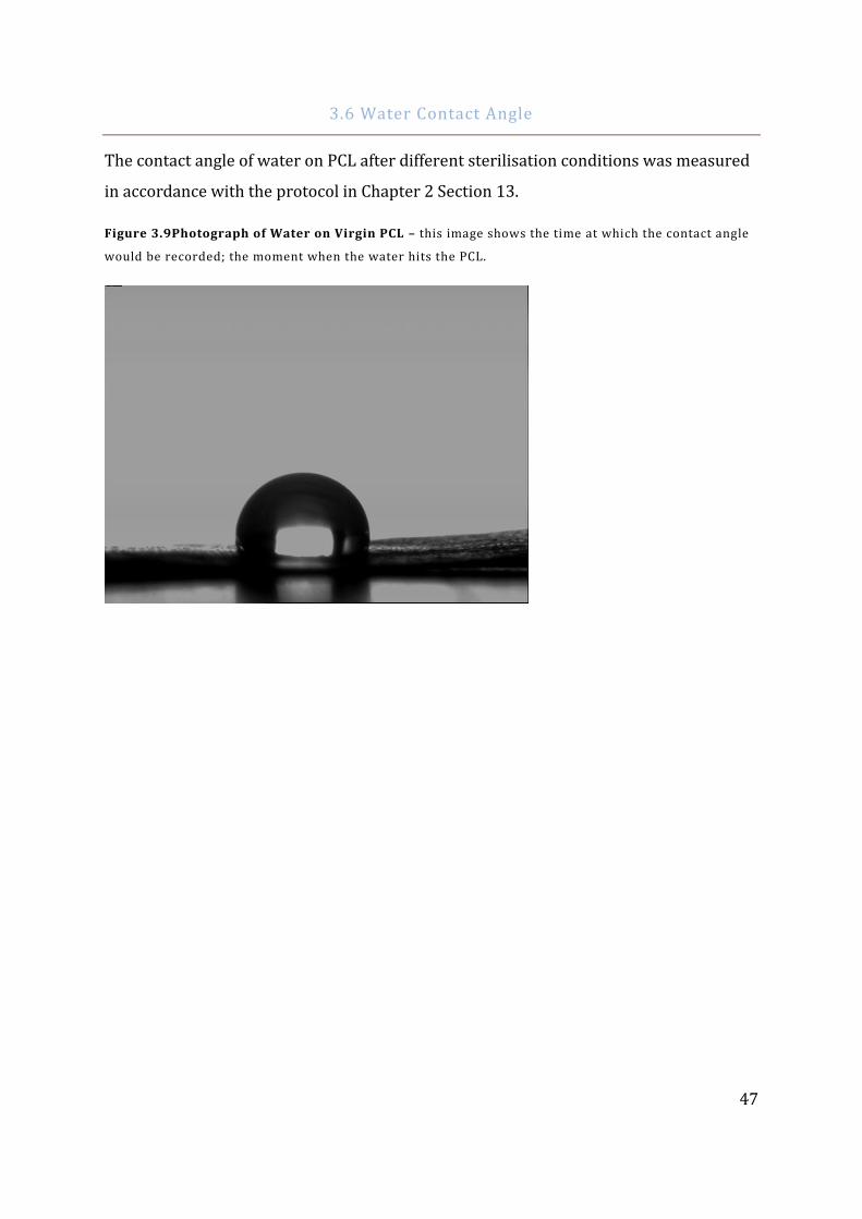
47
3.6 Water Contact Angle
The contact angle of water on PCL after different sterilisation conditions was measured
in accordance with the protocol in Chapter 2 Section 13.
Figure 3.9Photograph of Water on Virgin PCL – this image shows the time at which the contact angle
would be recorded; the moment when the water hits the PCL.
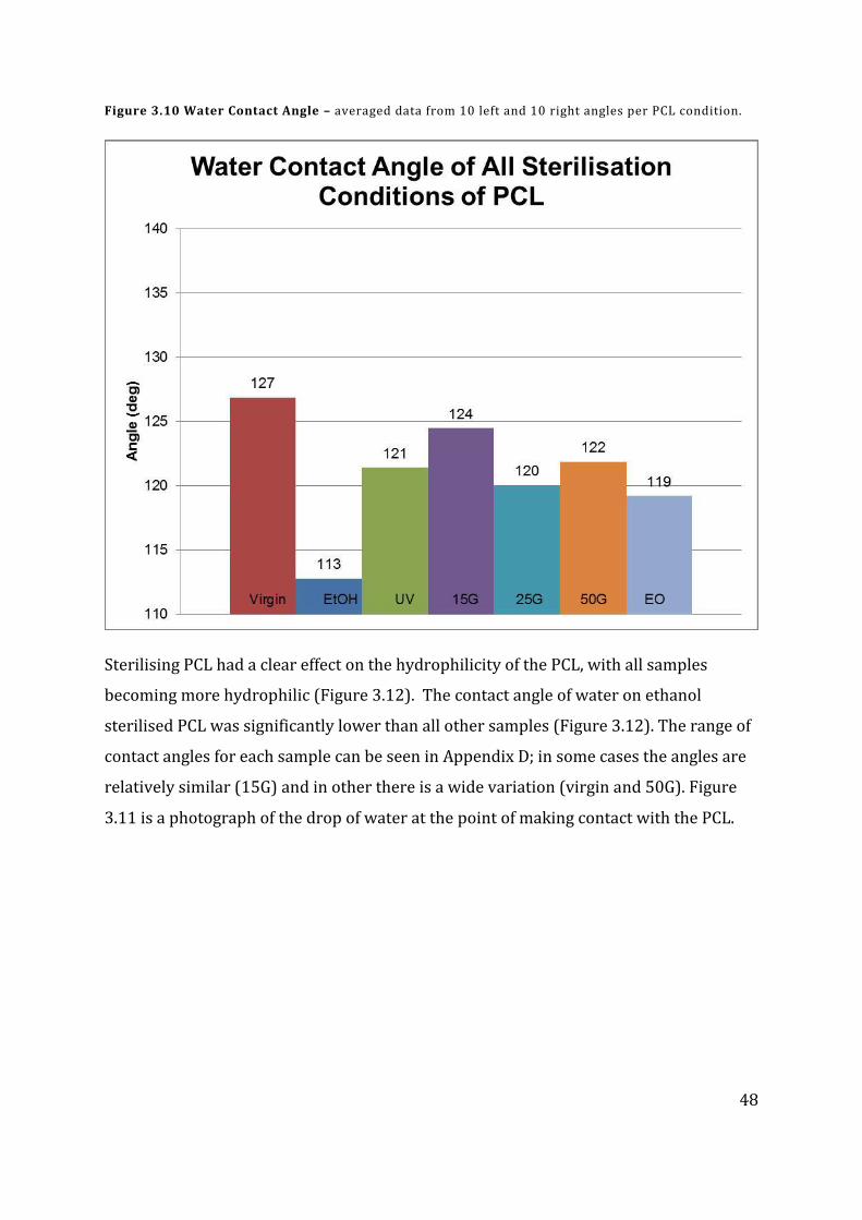
48
Figure 3.10 Water Contact Angle – averaged data from 10 left and 10 right angles per PCL condition.
Sterilising PCL had a clear effect on the hydrophilicity of the PCL, with all samples
becoming more hydrophilic (Figure 3.12). The contact angle of water on ethanol
sterilised PCL was significantly lower than all other samples (Figure 3.12). The range of
contact angles for each sample can be seen in Appendix D; in some cases the angles are
relatively similar (15G) and in other there is a wide variation (virgin and 50G). Figure
3.11 is a photograph of the drop of water at the point of making contact with the PCL.
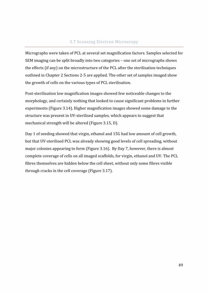
49
3.7 Scanning Electron Microscopy
Micrographs were taken of PCL at several set magnification factors. Samples selected for
SEM imaging can be split broadly into two categories – one set of micrographs shows
the effects (if any) on the microstructure of the PCL after the sterilisation techniques
outlined in Chapter 2 Sections 2-5 are applied. The other set of samples imaged show
the growth of cells on the various types of PCL sterilisation.
Post-sterilisation low magnification images showed few noticeable changes to the
morphology, and certainly nothing that looked to cause significant problems in further
experiments (Figure 3.14). Higher magnification images showed some damage to the
structure was present in UV-sterilised samples, which appears to suggest that
mechanical strength will be altered (Figure 3.15, D).
Day 1 of seeding showed that virgin, ethanol and 15G had low amount of cell growth,
but that UV-sterilised PCL was already showing good levels of cell spreading, without
major colonies appearing to form (Figure 3.16). By Day 7, however, there is almost
complete coverage of cells on all imaged scaffolds, for virgin, ethanol and UV. The PCL
fibres themselves are hidden below the cell sheet, without only some fibres visible
through cracks in the cell coverage (Figure 3.17).
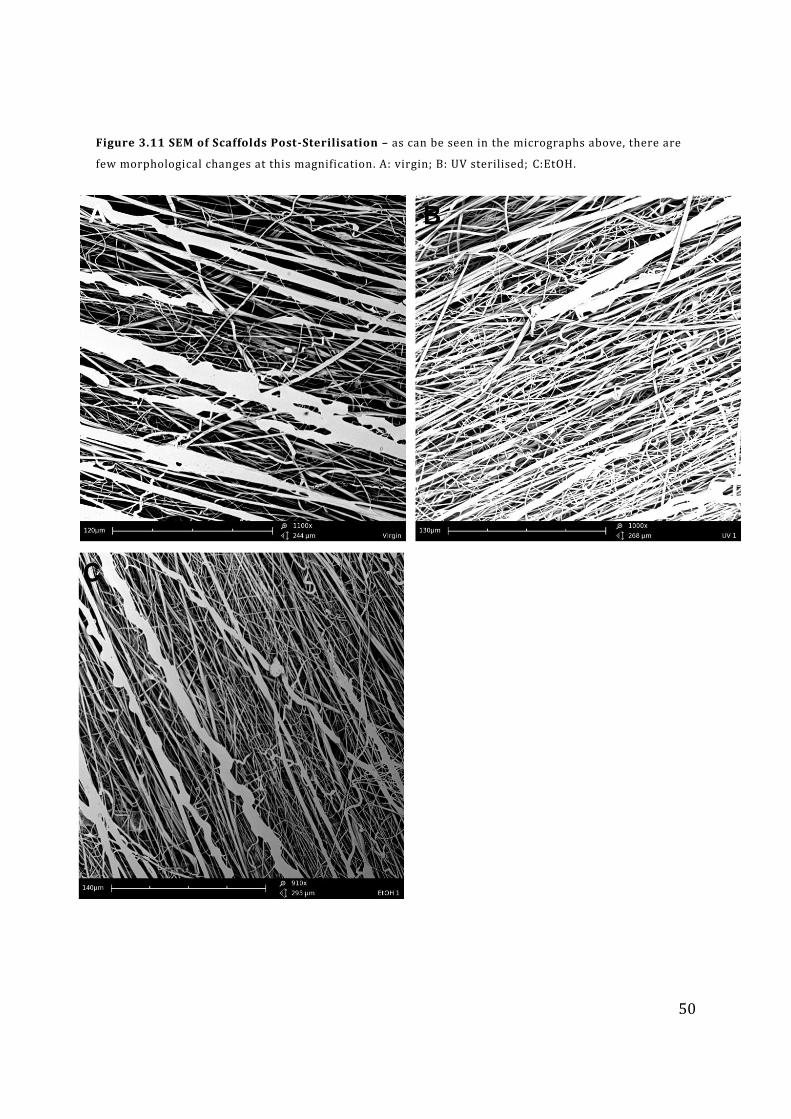
50
Figure 3.11 SEM of Scaffolds Post-Sterilisation – as can be seen in the micrographs above, there are
few morphological changes at this magnification. A: virgin; B: UV sterilised; C:EtOH.

51
Figure 3.12 SEM of Scaffolds Post-Sterilisation – a higher magnification shows that there is some
damage done to the fibres after sterilisation; some are broken, others appear dried -out and brittle (D).
A: ethanol sterilised; B: UV sterilised; C: ethanol sterilised; D, UV sterilised.
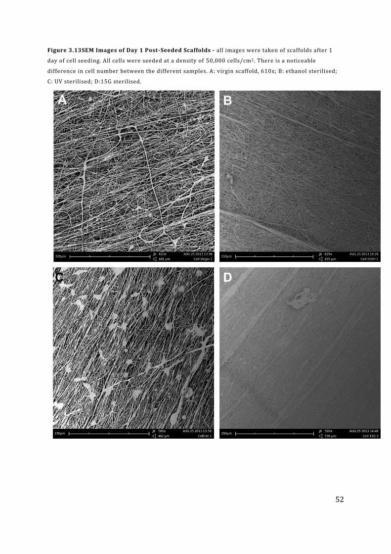
52
Figure 3.13SEM Images of Day 1 Post-Seeded Scaffolds - all images were taken of scaffolds after 1
day of cell seeding. All cells were seeded at a density of 50,000 cells/cm2. There is a noticeable
difference in cell number between the different samples. A: virgin scaffold, 610x; B: ethanol sterilised;
C: UV sterilised; D:15G sterilised.
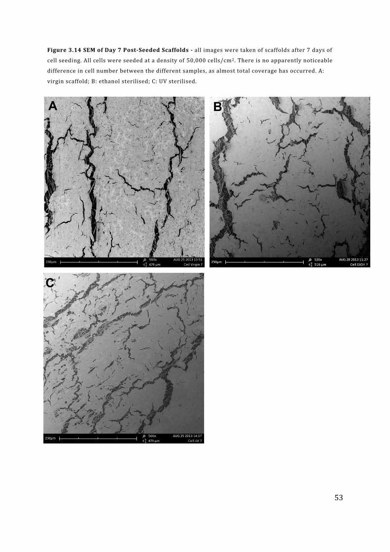
53
Figure 3.14 SEM of Day 7 Post-Seeded Scaffolds - all images were taken of scaffolds after 7 days of
cell seeding. All cells were seeded at a density of 50,000 cells/cm2. There is no apparently noticeable
difference in cell number between the different samples, as almost total coverage has occurred. A:
virgin scaffold; B: ethanol sterilised; C: UV sterilised.
54
Chapter 4 : Discussion and Conclusion
In the course of this research, six different conditions of PCL were tested against the
virgin samples and the results of the various experiments are recorded in Chapter 3:
Results. As mentioned in Chapter 1: Literature Review and Chapter 2: Materials and
Methods, each of the six sterilisation methods were chosen primarily for being known
to not cause immediate and severe damage to PCL (Rogers 2005). For example, had an
autoclave or dry-heat been used, then the high temperatures needed for effective
sterilisation (<100°C) would have irrevocably damaged the structure of PCL (Bosworth,
Gibb, and Downes 2012; Rogers 2005). Having seen that the protocols for the lab-based
methods of ethanol and UV sterilisation, and for industry-standard gamma irradiation
did not involve heating, these were chosen as the methods to be used (ISO 2002; Rogers
2005). In addition, a revised process for low-temperature ethylene oxide sterilisation
has recently gained popularity. Previously, ethylene oxide needed temperatures
comparable to the melting point of PCL, and without extensive tests on PCL, the high
temperatures would have had uncertain effects. However, the lower temperature
ethylene oxide sterilisation does not approach the melting point of PCL but remains a
permitted system for sterilisation.
The experiments which were performed seek to determine the effects of sterilisation on
PCL, and how reliable the cheaper and easier lab-based methods are in comparison to
the clinically approved ones. By extension, if there are similarities between the two
different classes of sterilisation, then the data published for lab-based sterilisation can
also be thought to approximate the behaviour of PCL for commercial sterilisation (for
which data is not as prevalent.) It is expected that there will be situations where one
sterilisation method is similar to another in a specific category (tensile strength or
melting point, for example); it is unlikely that there is one sterilisation method which
wholly mirrors the effects of another method.
55
4.1 Physiochemical Changes
The hierarchal nature of PCL provides many benefits to its physical and chemical
properties, but also creates a significant weakness. If the fibres are significantly
damaged, then flaws in the macrostructure will propagate, and PCL will start to behave
differently.
The changes could affect the structure and biocompatibility of the scaffold (due to
topological differences or the addition or removal of certain chemical groups) or the
degradation rate and products of the PCL. Altering the chain length, crystallinity or
crosslinking density will change the polymer behaviour, such stiffness, strength or
melting point. To determine the extent of these morphological or chemical changes, a
battery of experiments were performed.
Firstly, FT-IR was performed to determine the overall chemical structure of the PCL.
The virgin scaffold provided a control to show the spectra of PCL after it has been
commercially electrospun. There are several observable troughs in all of the spectra in
Figures 3.1 – 3.3 typical of PCL.
Intense troughs at around 1160 cm-1 (Figure 3.1, notation A) are indicative of a tertiary
alcohol (C-O), and troughs at 1750-1000 cm-1 show C-C and C=O bonds, with the trough
(Figure 3.1, notation B) showing the main absorbance spectra, and the smaller peaks to
the right showing scissoring, bending and stretching of the two bonds. Troughs at 2850-
3000 cm-1 (Figure 3.1, notation D) show the alkane C-H stretch which is also expected.
There is an extremely faint curve on the ethanol spectra (Figure 3.1 EtOH) which may
suggest that some ethanol is conserved through the sterilisation/cleaning process and
did not evaporate away. However, the curve is extremely shallow and the absorbance
percentage falls below that of the virgin spectra (Figure 3.1 Virgin). The only difference
in Figure 3.3 appears to be the change in absorbance percentages and not the presence
or absence of peaks themselves. It can be concluded, therefore, that there does not
appear to be a chemical change between each tested samples. Several conclusions can
be drawn from this. If the electrospun virgin PCL is a suitable substrate for cell growth,
as PCL is, then there should not be issues with cell growth from a chemistry perspective
56
(Aghdam et al. 2011; Qin and Wu 2011). Secondly, since there are no changes to the
chemistry, then it is reasonable to assume that the degradation products and behaviour
will remain constant. This will prove beneficial as chemical changes could alter the
degradation products or rate of degradation which in turn may affect cell viability
(Hutmacher and Cool 2007; Weir et al. 2003). Given the similarity between all of the
spectra, any one sterilisation method could easily replicate the chemical effects of
sterilisation for another method, assuming similar protocols as set out in Chapter 2 are
followed.
As the overall chemical makeup of the PCL was found to have not been altered, it was
next decided that an examination into the chemical layout and structure of the PCL
would give a clearer insight into sterilisation had affected it. The high energy radiation
used in gamma sterilisation is enough to cause both chain scission and cross-linking,
which often occur concurrently and in different ratios (Benson 2002; Gorna and
Gogolewski 2003). DSC analysis of the melting points showed very small rises in
temperatures for ethanol, UV and ethylene oxide, with ethylene oxide showing an
increase in melting point of 1.56°C (Figure 3.4). The gamma sterilisation caused a
decrease in melting point, with 15G and 25G giving almost identical results (Figure 3.4).
The difference in 50G could be due to the fact that the higher gamma levels often
require more than one pass through the sterilisation equipment, which could have
altered the ratio of cross-linking and scission. Virgin, ethanol and UV all seem to have
very similar chances of reproducing the effects of gamma irradiation or sterilisation by
ethylene oxide.
Changes in percentage crystallisation are clearer to see. All of the gamma sterilisation
methods show an increase in the region on 20% in crystallisation, along with ethylene
oxide. Ethanol also showed a moderate increase and UV a moderate decrease. Gamma
irradiation no doubt caused large-scale alterations to the amorphous phase of PCL,
changing it into a crystalline phase (Figure 3.4).
Both ethanol and ethylene oxide are highly invasive techniques; they are the only ones
used which involve chemical use and this may go some way to explain the changes in
crystallinity. UV also uses radiation as a sterilisation method, but uses lower energy
gamma radiation, and is there for considerably weaker (Benson 2002; Rogers 2005).
57
Given that for most systems the energy required for making bonds is generally higher
than breaking them (primarily due to entropy), crystalline phases may be removed and
restructured in favour of amorphous regions, therefore giving a lower percentage
crystallinity for UV than for the virgin sample (Figure 3.4)(Narkis 1984). The values of
all gamma conditions and ethylene oxide were over 50% for percentage crystallisation,
showing that the PCL had moved from the amorphous-region dominance shown in
virgin PCL (37% crystallinity) to crystalline-region dominance. Unfortunately, none of
the lab-based methods of sterilisation are able to replicate the percentage crystallinity
of PCL after sterilisation with the other methods.
Having determined from DSC that there were significant changes occurring in the
structure of the PCL after sterilisation, GPC was performed to see if any insight could be
gained into the ratio of chain scission to cross linking. A lower molecular weight is
indicative of chain scission, which is often accompanied by high energy processes
(Cottam et al. 2009). All of the gamma sterilisation methods showed a modest decrease
in molecular weight, up to 10% with the 50G sample and successive falls in average
molecular weight for each of the gamma doses (Figure 3.9), showing a move towards
overall chain scission. Shorter chains will generally melt at a lower temperature, and
reviewing the data from the DSC shows that the gamma sterilised PCL had lower
melting points than the virgin sample (Figure 3.4). Remembering that PCL is a polymer,
it is quite possible that the scissioned ends from the gamma areas re-polymerised and
formed tightly packed crystalline regions, explaining the major change in percentage
crystallinity seen in the DSC data (Figure 3.4) Ethanol shows no change, as it did with
the melting point on the DSC, and only minimal changes with the percentage
crystallinity (Figures 3.4 and 3.9). UV showed a 20% increase in molecular weight,
suggesting that cross-linking was by far the dominant effect here (Figure 3.9). This is
again consistent with the percentage crystallinity data, which showed a decrease in
crystallisation for UV, contrary to the large increases in the gamma values (Figure 3.4).
A change average molecular weight would also likely have an effect on the mechanical
properties of PCL. Virgin PCL can make a reasonable approximation of the effects of the
clinical-grader sterilisation, however if some sterilisation is needed, then ethanol will
also work.
58
A different angle of approach was to look at the hydrophobicity and hydrophilicity of
the PCL, and to observe any changes in the contact angle of water on PCL. PCL is an
averagely hydrophobic surface with low surface energy (Weir et al. 2003). All
sterilisation methods lowered the contact angle of PCL, making it more hydrophilic
(Figure 3.12). UV, all gamma and ethylene oxide all decreased the contact angle by 2-
6%, whilst ethanol had a significant effect, reducing the contact angle by 14°.
It is interesting to note that ethanol is a highly hydrophilic and hydroscopic substance,
and it is possible that there was some modification or absorbency of ethanol onto the
PCL.
If there was surface modification, and not straight absorbency of ethanol, this would not
necessarily be picked up during FT-IR due to PCL containing bound –OH groups. None
of changes in PCL alters PCL enough to be considered hydrophilic(a contact angle of 90°
is generally the threshold for hydrophilicity) but there has clearly been alteration
which would favour cell attachment (Huang et al. 2003; Pham, Sharma, and Mikos 2006;
Cipitria et al. 2011). 15G is the clinical-grade sterilisation method that is most similar to
the virgin sample, and UV is the most similar to 15G, although the differences between
all of the clinical sterilisation methods are minimal.
Having looked at the changes that were in the chemistry of PCL, the next set of
experiments sought to determine the effects of sterilisation at the macroscopic level in
the form of mechanical and tensile testing. When implanting a biomaterial in vivo it is
essential that the biomaterial can withstand the mechanical load placed on it, whilst not
interfering with the normal function of the body; this is especially true in terms of
regenerative medicine, where failure can be disastrous for the body’s recovery (Kohane
and Langer 2008; Olbrich et al. 2007; Kumbar et al. 2008). However, it is also difficult to
model exactly how the material will behave; often in vivo animal tests are the only way
to perform the experiments, but an element of scalability is needed to predict how the
material will work in humans (Sun et al. 2010).
From the outset, it was likely that there would be an effect on the mechanical
properties; sterilisation had affected the outcome of most of the other tests so far, and
changes in mechanical properties were easier to predict than the experiments
59
previously done. Average molecular weight, as tested using GPC, changed for all but one
of the conditions (ethanol) and so changes in tensile testing were predicted (Figure 3.9).
When tensile testing is performed, one of the commonly cited values is that of Young’s
modulus, the ratio of stress to strain in a material, whilst the material is in a state which
obeys Hooke’s law. Young’s modulus can easily be compared between materials of all
classes, and often provides a baseline against which materials can be judged against
each other.
In all but one case, the Young’s modulus fell considerably when compared to the virgin
sample, this ranged from 8.68 – 49.23 MPa, representing a drop to 37% of the virgin
sample’s original strength for the 25G sample (Figure 3.5).
Interestingly, 50G had a higher average Young’s modulus than 25G despite the dose of
radiation for 50G being twice that of 25G, and 50G having a higher overall percentage
crystallinity. Ethanol and ethylene oxide again showed very similar results, suggesting
that their physical methods of sterilisation, along with chemical similarity, had a
comparable effect on PCL (Figure 3.5). For a second time, UV defied the trend by
increasing in Young’s modulus by 18.81 MPa, similar to the GPC result (Figure 3.5 and
3.9).
Ultimate tensile strength is the maximum stress that the material can take at failure. In
the context of PCL, a ductile fibrous material, it is assumed that the ultimate tensile
strength will be at the point when the first fibre fails. Examination of the stress-strain
curves shows that in some cases the material carried on deforming for a long time after
the ultimate tensile strength point (the apex of the graph) had been met. UV was shown
to have very similar ultimate tensile strengths as 25G and ethylene oxide (10.32 MPa
compared to 10.22 and 10.72 MPa, respectively), all of which were higher than virgin
and ethanol (8.72 and 8.51 MPa) (Figure 3.6). 15G and 50G were both lower than the
virgin sample, with 50G again having the lowest value, in keeping with the prediction
that multiple doses of gamma radiation will weaken the structure (Rogers 2005).
Strain is the maximum elongation that a sample can take before failure, and the
maximum strain point is often closely related to the ultimate tensile strength as they
both peak when all the fibres are bearing their maximum load. Although the data shown
60
is the strain at failure and not the strain at the maximum load point, the two graphs of
strain and ultimate tensile strength are reasonably similar (Figures 3.6 and 3.7). Again,
50G has the lowest value, but this time it is only 25G and ethylene oxide that have
higher values than the virgin sample (0.4 and 0.43, compared with 0.31), with ethanol,
UV and 15G have comparable strains to virgin. The 50G value (0.19) is significantly
lower than all of the other values, and is almost certainly related to the high degree of
crystallinity that 50G exhibited. Changes in the mechanical properties of UV scaffolds,
as predicted by the changes in morphology under SEM imaging (Figure 3.15 D) were
borne out by the mechanical testing data. However, the results counter-intuitively
showed an increase or no change in mechanical strength, rather than a decrease which
would have been expected by the apparent damage seen (Figure 3.15).
It is possible that the shrinking that seemed to occur as a result of UV radiation helped
to remove flaws present in the structure, whist at the same time lowering the amount of
force placed on the cross-sectional area.
Disappointingly, it is difficult to draw any overarching conclusions from the mechanical
properties. The data shown finds itself in agreement with another study, whose authors
also observed the difficulties in drawing any conclusions as (specifically for the gamma
samples) whilst there is a trend in GPC and DSC data, this is not borne out in the tensile
testing data (Bosworth, Gibb, and Downes 2012). A lack of a dose-dependent pattern
hampers the possibility of finding a perfect method of reproducing sterilisation effects.
15G seems to be the closest to the mechanical properties of the virgin sample, and
ethanol sterilisation will do a sufficient job of representing 15G in terms of mechanical
properties.
4.2 Cellular Response
Whilst learning how the PCL scaffolds physically behave after sterilisation is important,
the essential tests that had to be performed involved learning how the scaffold would
react to cells. It is the responses of the cells to the different types of sterilisation which
will ultimately decide whether or not a certain sterilisation method can be used
clinically. Expanding on that slightly in the context of this research, a lab-based
sterilisation method would be expected to replicate the effects of clinically permissible
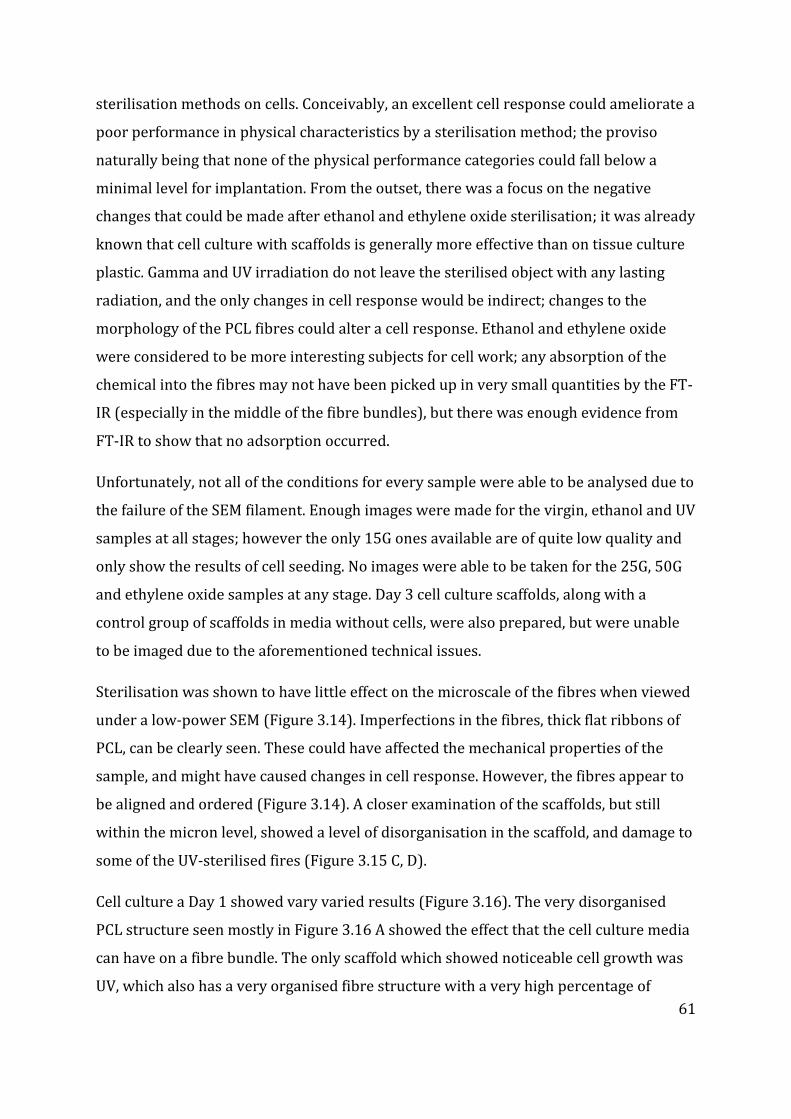
61
sterilisation methods on cells. Conceivably, an excellent cell response could ameliorate a
poor performance in physical characteristics by a sterilisation method; the proviso
naturally being that none of the physical performance categories could fall below a
minimal level for implantation. From the outset, there was a focus on the negative
changes that could be made after ethanol and ethylene oxide sterilisation; it was already
known that cell culture with scaffolds is generally more effective than on tissue culture
plastic. Gamma and UV irradiation do not leave the sterilised object with any lasting
radiation, and the only changes in cell response would be indirect; changes to the
morphology of the PCL fibres could alter a cell response. Ethanol and ethylene oxide
were considered to be more interesting subjects for cell work; any absorption of the
chemical into the fibres may not have been picked up in very small quantities by the FT-
IR (especially in the middle of the fibre bundles), but there was enough evidence from
FT-IR to show that no adsorption occurred.
Unfortunately, not all of the conditions for every sample were able to be analysed due to
the failure of the SEM filament. Enough images were made for the virgin, ethanol and UV
samples at all stages; however the only 15G ones available are of quite low quality and
only show the results of cell seeding. No images were able to be taken for the 25G, 50G
and ethylene oxide samples at any stage. Day 3 cell culture scaffolds, along with a
control group of scaffolds in media without cells, were also prepared, but were unable
to be imaged due to the aforementioned technical issues.
Sterilisation was shown to have little effect on the microscale of the fibres when viewed
under a low-power SEM (Figure 3.14). Imperfections in the fibres, thick flat ribbons of
PCL, can be clearly seen. These could have affected the mechanical properties of the
sample, and might have caused changes in cell response. However, the fibres appear to
be aligned and ordered (Figure 3.14). A closer examination of the scaffolds, but still
within the micron level, showed a level of disorganisation in the scaffold, and damage to
some of the UV-sterilised fires (Figure 3.15 C, D).
Cell culture a Day 1 showed vary varied results (Figure 3.16). The very disorganised
PCL structure seen mostly in Figure 3.16 A showed the effect that the cell culture media
can have on a fibre bundle. The only scaffold which showed noticeable cell growth was
UV, which also has a very organised fibre structure with a very high percentage of
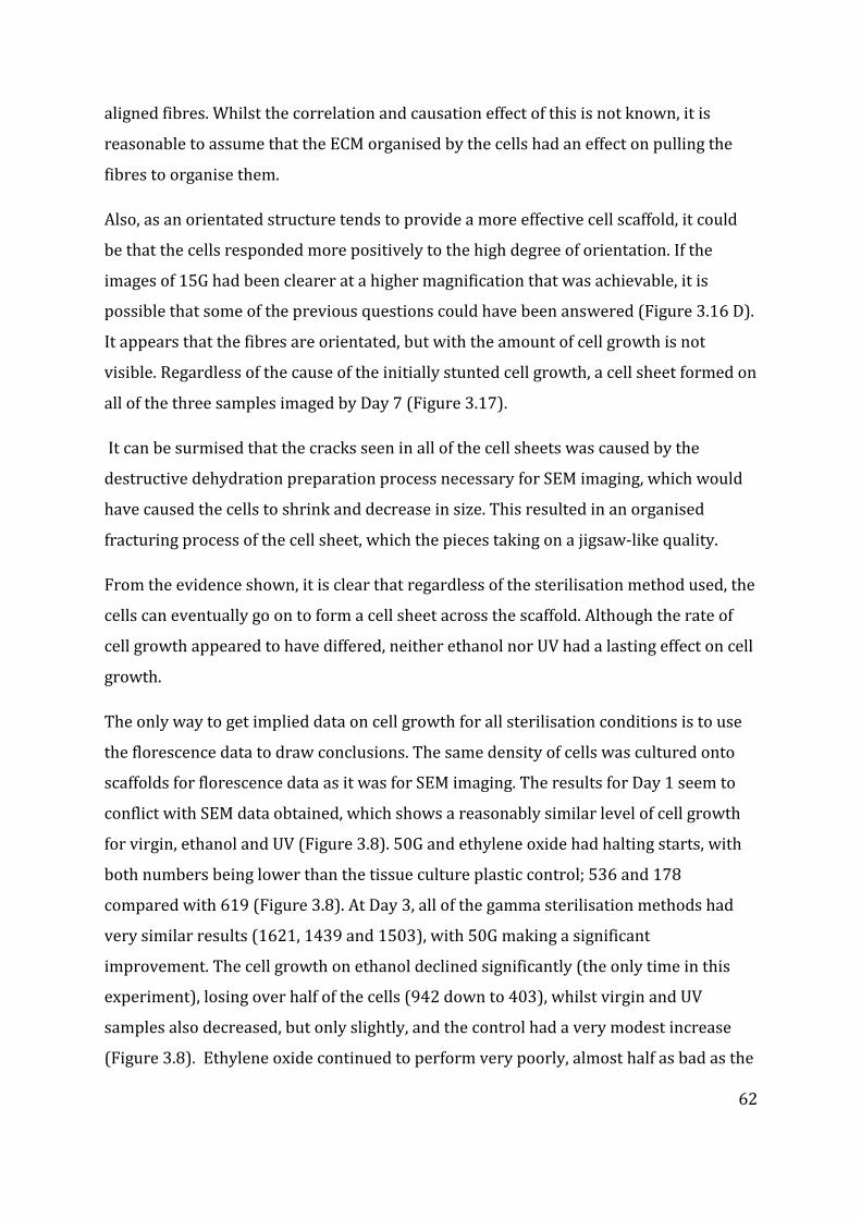
62
aligned fibres. Whilst the correlation and causation effect of this is not known, it is
reasonable to assume that the ECM organised by the cells had an effect on pulling the
fibres to organise them.
Also, as an orientated structure tends to provide a more effective cell scaffold, it could
be that the cells responded more positively to the high degree of orientation. If the
images of 15G had been clearer at a higher magnification that was achievable, it is
possible that some of the previous questions could have been answered (Figure 3.16 D).
It appears that the fibres are orientated, but with the amount of cell growth is not
visible. Regardless of the cause of the initially stunted cell growth, a cell sheet formed on
all of the three samples imaged by Day 7 (Figure 3.17).
It can be surmised that the cracks seen in all of the cell sheets was caused by the
destructive dehydration preparation process necessary for SEM imaging, which would
have caused the cells to shrink and decrease in size. This resulted in an organised
fracturing process of the cell sheet, which the pieces taking on a jigsaw-like quality.
From the evidence shown, it is clear that regardless of the sterilisation method used, the
cells can eventually go on to form a cell sheet across the scaffold. Although the rate of
cell growth appeared to have differed, neither ethanol nor UV had a lasting effect on cell
growth.
The only way to get implied data on cell growth for all sterilisation conditions is to use
the florescence data to draw conclusions. The same density of cells was cultured onto
scaffolds for florescence data as it was for SEM imaging. The results for Day 1 seem to
conflict with SEM data obtained, which shows a reasonably similar level of cell growth
for virgin, ethanol and UV (Figure 3.8). 50G and ethylene oxide had halting starts, with
both numbers being lower than the tissue culture plastic control; 536 and 178
compared with 619 (Figure 3.8). At Day 3, all of the gamma sterilisation methods had
very similar results (1621, 1439 and 1503), with 50G making a significant
improvement. The cell growth on ethanol declined significantly (the only time in this
experiment), losing over half of the cells (942 down to 403), whilst virgin and UV
samples also decreased, but only slightly, and the control had a very modest increase
(Figure 3.8). Ethylene oxide continued to perform very poorly, almost half as bad as the
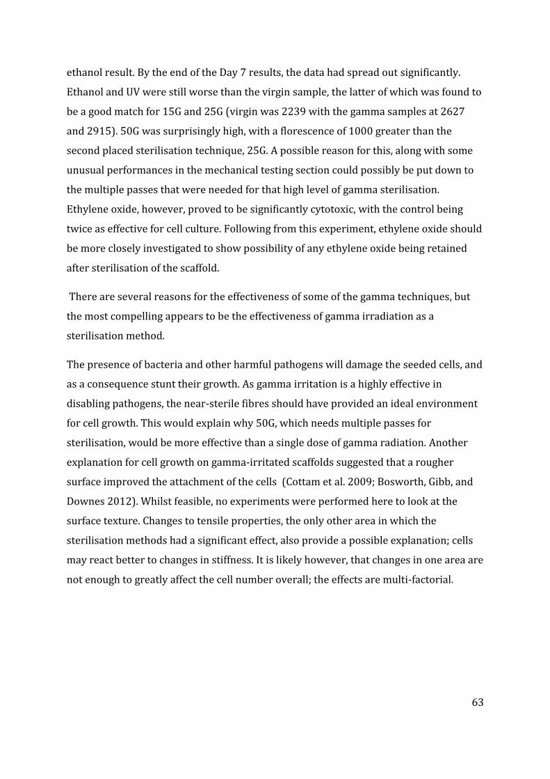
63
ethanol result. By the end of the Day 7 results, the data had spread out significantly.
Ethanol and UV were still worse than the virgin sample, the latter of which was found to
be a good match for 15G and 25G (virgin was 2239 with the gamma samples at 2627
and 2915). 50G was surprisingly high, with a florescence of 1000 greater than the
second placed sterilisation technique, 25G. A possible reason for this, along with some
unusual performances in the mechanical testing section could possibly be put down to
the multiple passes that were needed for that high level of gamma sterilisation.
Ethylene oxide, however, proved to be significantly cytotoxic, with the control being
twice as effective for cell culture. Following from this experiment, ethylene oxide should
be more closely investigated to show possibility of any ethylene oxide being retained
after sterilisation of the scaffold.
There are several reasons for the effectiveness of some of the gamma techniques, but
the most compelling appears to be the effectiveness of gamma irradiation as a
sterilisation method.
The presence of bacteria and other harmful pathogens will damage the seeded cells, and
as a consequence stunt their growth. As gamma irritation is a highly effective in
disabling pathogens, the near-sterile fibres should have provided an ideal environment
for cell growth. This would explain why 50G, which needs multiple passes for
sterilisation, would be more effective than a single dose of gamma radiation. Another
explanation for cell growth on gamma-irritated scaffolds suggested that a rougher
surface improved the attachment of the cells (Cottam et al. 2009; Bosworth, Gibb, and
Downes 2012). Whilst feasible, no experiments were performed here to look at the
surface texture. Changes to tensile properties, the only other area in which the
sterilisation methods had a significant effect, also provide a possible explanation; cells
may react better to changes in stiffness. It is likely however, that changes in one area are
not enough to greatly affect the cell number overall; the effects are multi-factorial.
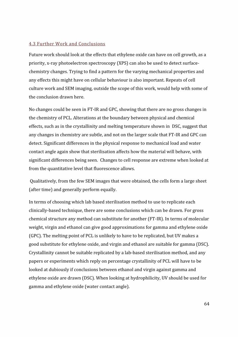
64
4.3 Further Work and Conclusions
Future work should look at the effects that ethylene oxide can have on cell growth, as a
priority, x-ray photoelectron spectroscopy (XPS) can also be used to detect surface-
chemistry changes. Trying to find a pattern for the varying mechanical properties and
any effects this might have on cellular behaviour is also important. Repeats of cell
culture work and SEM imaging, outside the scope of this work, would help with some of
the conclusion drawn here.
No changes could be seen in FT-IR and GPC, showing that there are no gross changes in
the chemistry of PCL. Alterations at the boundary between physical and chemical
effects, such as in the crystallinity and melting temperature shown in DSC, suggest that
any changes in chemistry are subtle, and not on the larger scale that FT-IR and GPC can
detect. Significant differences in the physical response to mechanical load and water
contact angle again show that sterilisation affects how the material will behave, with
significant differences being seen. Changes to cell response are extreme when looked at
from the quantitative level that fluorescence allows.
Qualitatively, from the few SEM images that were obtained, the cells form a large sheet
(after time) and generally perform equally.
In terms of choosing which lab based sterilisation method to use to replicate each
clinically-based technique, there are some conclusions which can be drawn. For gross
chemical structure any method can substitute for another (FT-IR). In terms of molecular
weight, virgin and ethanol can give good approximations for gamma and ethylene oxide
(GPC). The melting point of PCL is unlikely to have to be replicated, but UV makes a
good substitute for ethylene oxide, and virgin and ethanol are suitable for gamma (DSC).
Crystallinity cannot be suitable replicated by a lab-based sterilisation method, and any
papers or experiments which reply on percentage crystallinity of PCL will have to be
looked at dubiously if conclusions between ethanol and virgin against gamma and
ethylene oxide are drawn (DSC). When looking at hydrophilicity, UV should be used for
gamma and ethylene oxide (water contact angle).
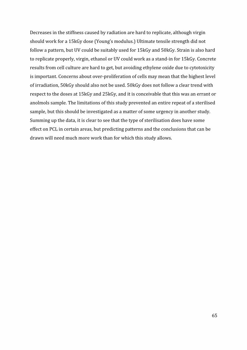
65
Decreases in the stiffness caused by radiation are hard to replicate, although virgin
should work for a 15kGy dose (Young’s modulus.) Ultimate tensile strength did not
follow a pattern, but UV could be suitably used for 15kGy and 50kGy. Strain is also hard
to replicate properly, virgin, ethanol or UV could work as a stand-in for 15kGy. Concrete
results from cell culture are hard to get, but avoiding ethylene oxide due to cytotoxicity
is important. Concerns about over-proliferation of cells may mean that the highest level
of irradiation, 50kGy should also not be used. 50kGy does not follow a clear trend with
respect to the doses at 15kGy and 25kGy, and it is conceivable that this was an errant or
anolmols sample. The limitations of this study prevented an entire repeat of a sterilised
sample, but this should be investigated as a matter of some urgency in another study.
Summing up the data, it is clear to see that the type of sterilisation does have some
effect on PCL in certain areas, but predicting patterns and the conclusions that can be
drawn will need much more work than for which this study allows.
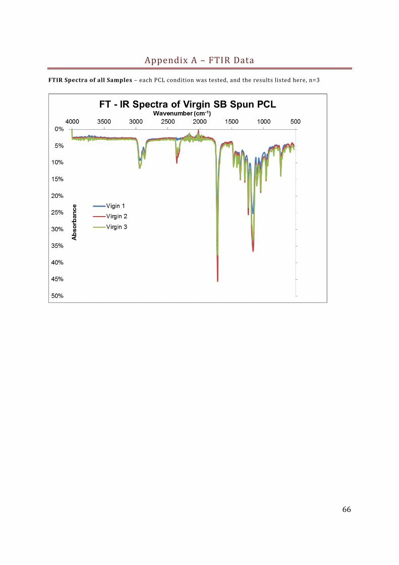
66
Appendix A – FTIR Data
FTIR Spectra of all Samples – each PCL condition was tested, and the results listed here, n=3
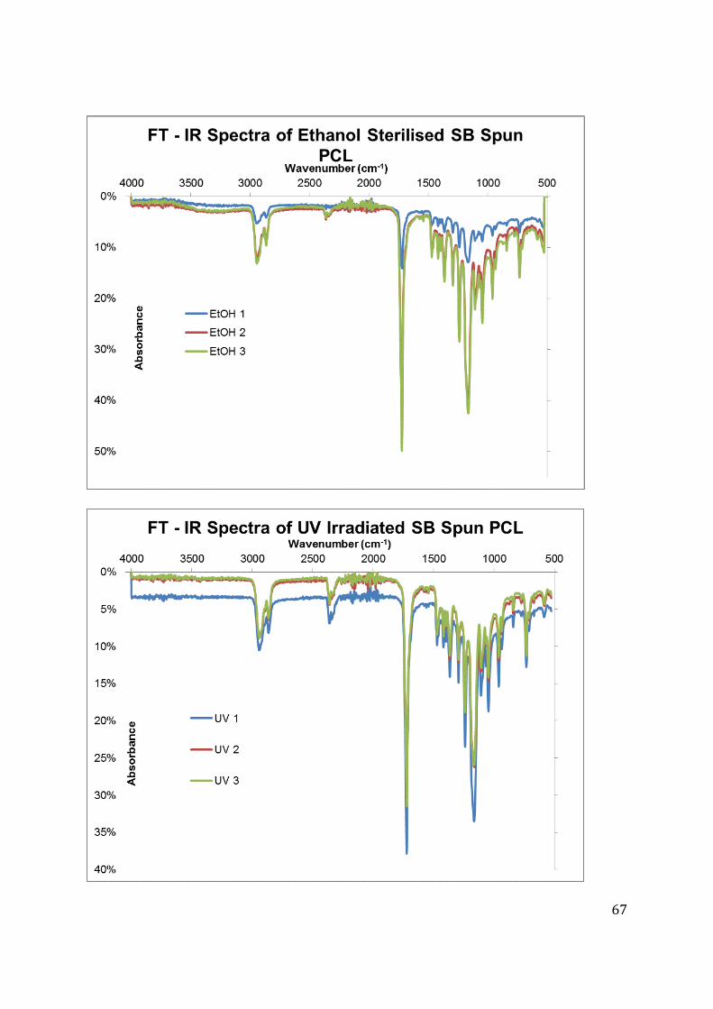
67
68
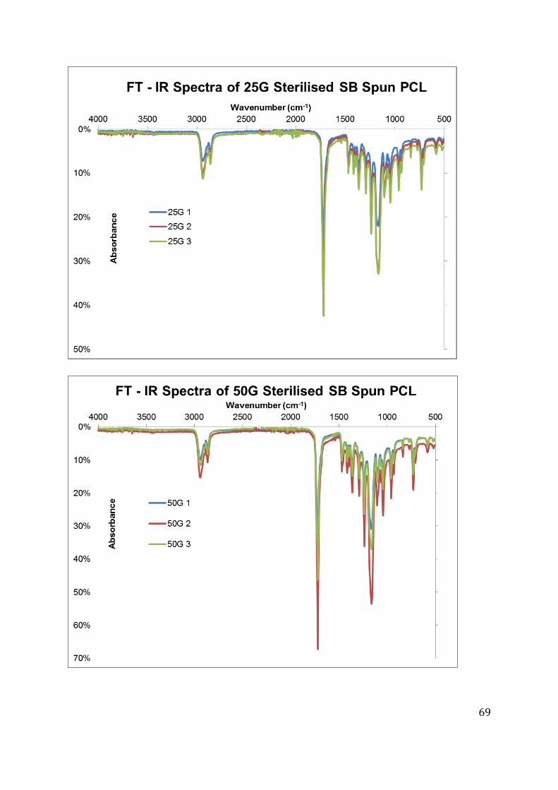
69
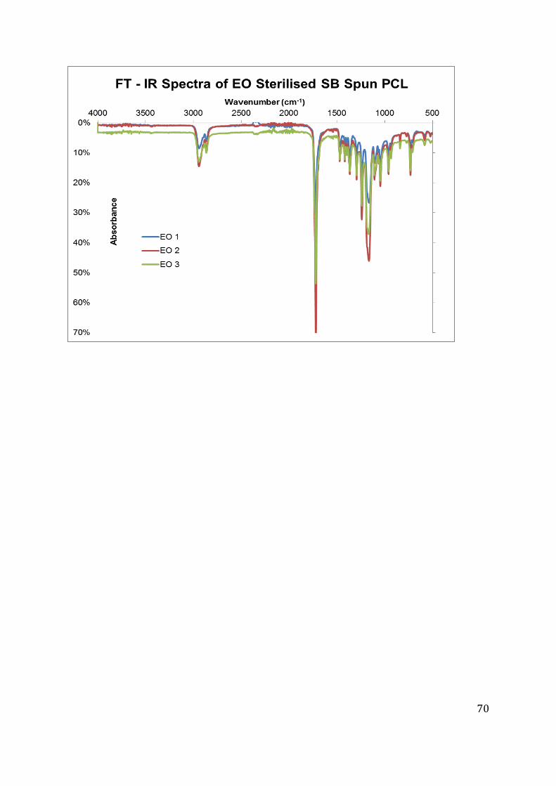
70
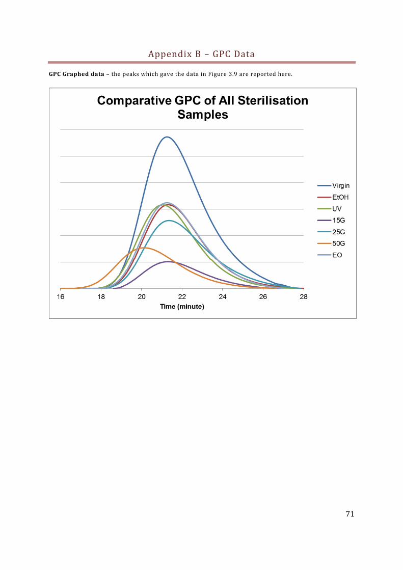
71
Appendix B – GPC Data
GPC Graphed data – the peaks which gave the data in Figure 3.9 are reported here.
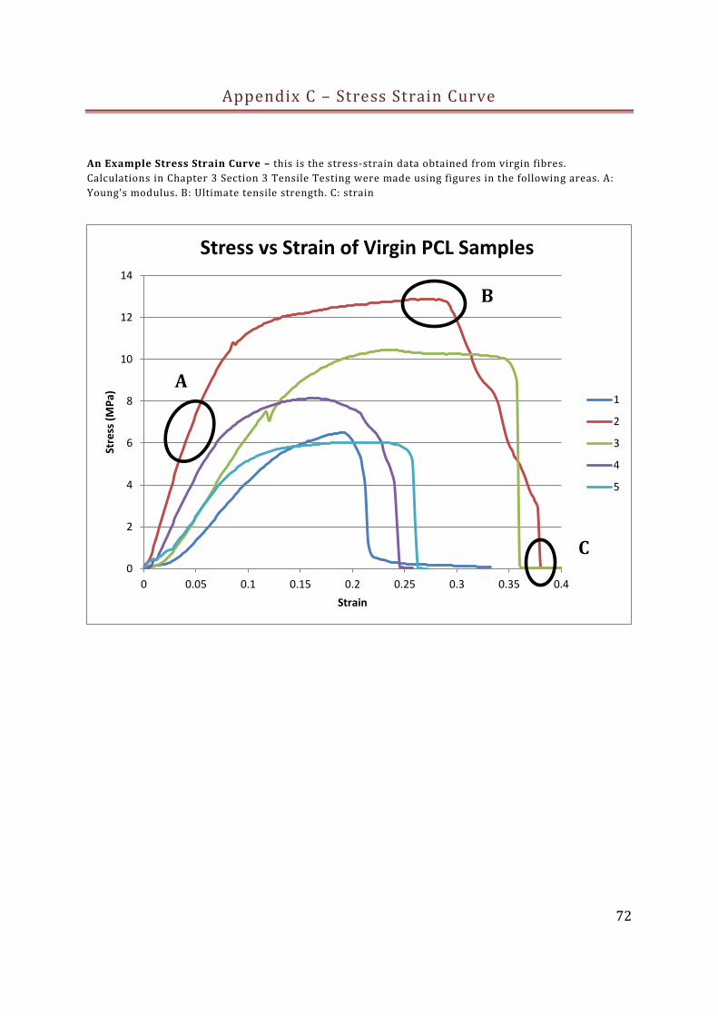
72
Appendix C – Stress Strain Curve
An Example Stress Strain Curve – this is the stress-strain data obtained from virgin fibres.
Calculations in Chapter 3 Section 3 Tensile Testing were made using figures in the following areas. A:
Young’s modulus. B: Ultimate tensile strength. C: strain
0
2
4
6
8
10
12
14
0 0.05 0.1 0.15 0.2 0.25 0.3 0.35 0.4
Stre
ss (
MP
a)
Strain
Stress vs Strain of Virgin PCL Samples
1
2
3
4
5
B
A
C
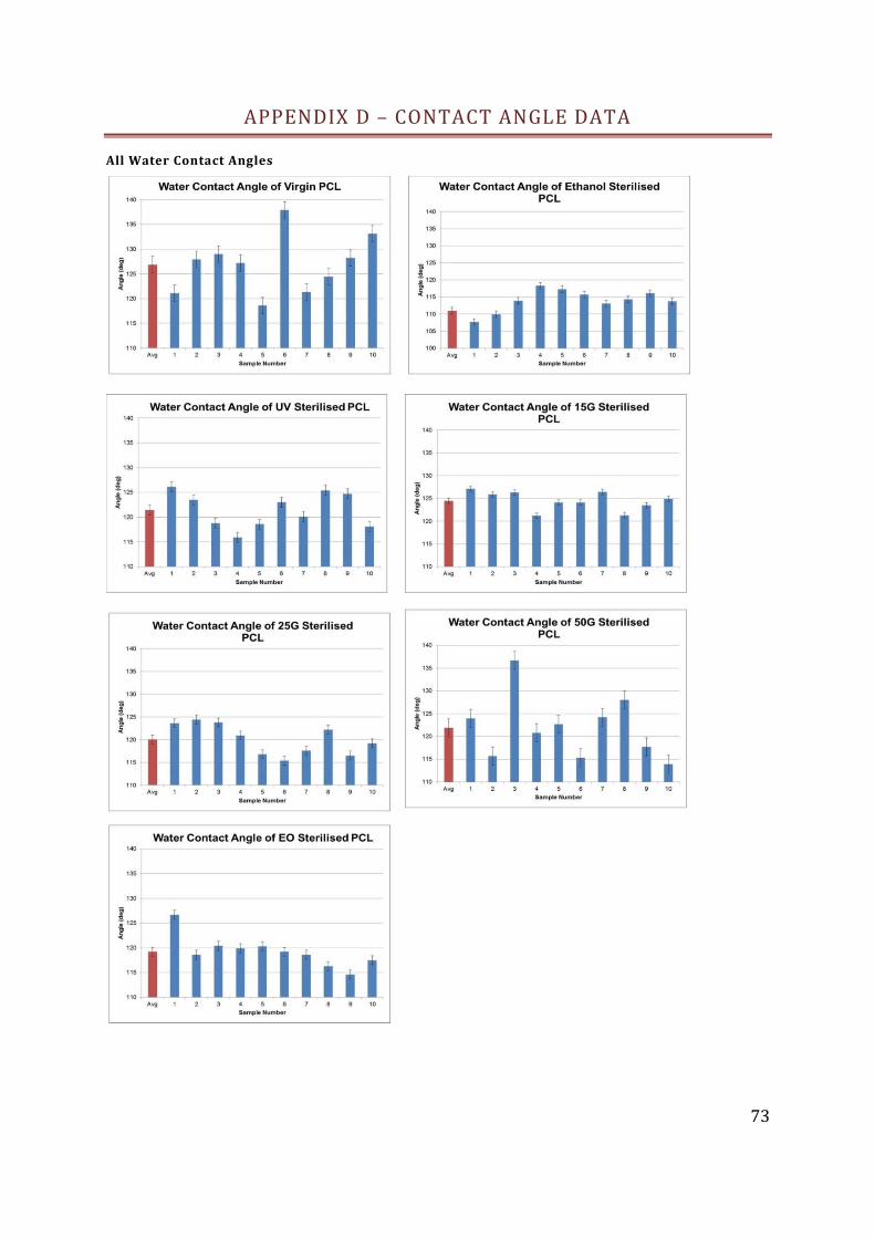
73
APPENDIX D – CONTACT ANGLE DATA
All Water Contact Angles
74
Chapter 5 : References
Adrian, JC, and Arthur Gross. 1979. “A New Method of Sterilization: The Carbon Dioxide
Laser.” Journal of Oral Pathology & Medicine: 60–61.
http://onlinelibrary.wiley.com/doi/10.1111/j.1600-0714.1979.tb01623.x/abstract.
Aghdam, Rouhollah Mehdinavaz, Siamak Najarian, Saeed Shakhesi, Samaneh Khanlari,
Keyvan Shaabani, and Shahriar Sharifi. 2011. “Investigating the Effect of PGA on
Physical and Mechanical Properties of Electrospun PCL / PGA Blend Nanofibers.”
Journal of Applied Polymer Science 124. doi:10.1002/app.
Baati, Tarek, Fanchon Bourasset, Najla Gharbi, Leila Njim, Manef Abderrabba, Abdelhamid
Kerkeni, Henri Szwarc, and Fathi Moussa. 2012. “The Prolongation of the Lifespan of
Rats by Repeated Oral Administration of [60]fullerene.” Biomaterials (April 10): 1–11.
doi:10.1016/j.biomaterials.2012.03.036.
http://www.ncbi.nlm.nih.gov/pubmed/22498298.
Benson, Roberto S. 2002. “Use of Radiation in Biomaterials Science.” Nuclear Instruments
and Methods in Physics Research Section B: Beam Interactions with Materials and
Atoms 191 (1-4) (May): 752–757. doi:10.1016/S0168-583X(02)00647-X.
http://linkinghub.elsevier.com/retrieve/pii/S0168583X0200647X.
Bhardwaj, Nandana, and Subhas C Kundu. 2010. “Electrospinning: a Fascinating Fiber
Fabrication Technique.” Biotechnology Advances 28 (3): 325–47.
doi:10.1016/j.biotechadv.2010.01.004. http://www.ncbi.nlm.nih.gov/pubmed/20100560.
Bianco, A., B. M. Bozzo, C. Del Gaudio, I. Cacciotti, I. Armentano, M. Dottori, F. D’Angelo,
S. Martino, A. Orlacchio, and J. M. Kenny. 2011. “Poly (L-Lactic Acid)/calcium-
Deficient Nanohydroxyapatite Electrospun Mats for Bone Marrow Stem Cell Cultures.”
Journal of Bioactive and Compatible Polymers 26 (3) (May 25): 225–241.
doi:10.1177/0883911511406250.
http://jbc.sagepub.com/cgi/doi/10.1177/0883911511406250.
Bosworth, L A, A Gibb, and S Downes. 2012. “Gamma Irradiation of Electrospun Poly ( e-
Caprolactone ) Fibers Affects Material Properties but Not Cell Response.” Journal of
Polymer Science: 870–876. doi:10.1002/polb.23072.
Brétagnol, Frédéric, Hubert Rauscher, Marina Hasiwa, Ondrej Kylián, Giaccomo Ceccone,
Len Hazell, Alan J Paul, Olivier Lefranc, and François Rossi. 2008. “The Effect of
Sterilization Processes on the Bioadhesive Properties and Surface Chemistry of a
Plasma-Polymerized Polyethylene Glycol Film: XPS Characterization and L929 Cell
Proliferation Tests.” Acta Biomaterialia 4 (6) (November): 1745–51.
doi:10.1016/j.actbio.2008.06.013. http://www.ncbi.nlm.nih.gov/pubmed/18676191.
Cipitria, A., A. Skelton, T. R. Dargaville, P. D. Dalton, and D. W. Hutmacher. 2011.
“Design, Fabrication and Characterization of PCL Electrospun Scaffolds—a Review.”
Journal of Materials Chemistry 21 (26): 9419. doi:10.1039/c0jm04502k.
http://xlink.rsc.org/?DOI=c0jm04502k.
75
Cooley, J F. 1902. “Apparatus for Electrically Dispersing Fluids”. U.P. Office.
Cottam, Emily, David W L Hukins, Kenneth Lee, Christopher Hewitt, and Mike J Jenkins.
2009. “Effect of Sterilisation by Gamma Irradiation on the Ability of Polycaprolactone
(PCL) to Act as a Scaffold Material.” Medical Engineering & Physics 31 (2) (March):
221–6. doi:10.1016/j.medengphy.2008.07.005.
http://www.ncbi.nlm.nih.gov/pubmed/18760952.
Croisier, F, A Duwez, C Jérôme, A F Léonard, K O Van Der Werf, P J Dijkstra, and M L
Bennink. 2012. “Mechanical Testing of Electrospun PCL Fibers.” Acta Biomaterialia 8
(1): 218–224. doi:10.1016/j.actbio.2011.08.015.
http://dx.doi.org/10.1016/j.actbio.2011.08.015.
Curran, J M, Z Tang, and J a Hunt. 2009. “PLGA Doping of PCL Affects the Plastic Potential
of Human Mesenchymal Stem Cells, Both in the Presence and Absence of Biological
Stimuli.” Journal of Biomedical Materials Research. Part A 89 (1) (April): 1–12.
doi:10.1002/jbm.a.31966. http://www.ncbi.nlm.nih.gov/pubmed/18404713.
Dahlin, RL, FK Kasper, and Antonios G Mikos. 2011. “Polymeric Nanofibers in Tissue
Engineering.” Tissue Engineering 17 (5). doi:10.1089/ten.teb.2011.0238.
http://www.liebertonline.com/doi/abs/10.1089/ten.TEB.2011.0238.
Deitzel, J.M, J Kleinmeyer, D Harris, and N.C Beck Tan. 2001. “The Effect of Processing
Variables on the Morphology of Electrospun Nanofibers and Textiles.” Polymer 42 (1)
(January): 261–272. doi:10.1016/S0032-3861(00)00250-0.
http://linkinghub.elsevier.com/retrieve/pii/S0032386100002500.
Dellinger, E Patchen, Donald E Fry, Claudia Wright, Allen Ma, Karina Carr, and Lisa Red.
2005. “Use of Antimicrobial Prophylaxis for Major Surgery.” Arch Surg 140.
Doshi, Jayesh, and Darrell Reneker. 2011. “Electrospinning Process and Applications of
Electrospun Fibers.” Journal of Cellular Biochemistry 112 (11) (November): C1.
doi:10.1002/jcb.23404. http://www.ncbi.nlm.nih.gov/pubmed/22008972.
Ebersole, Gregory C, Evan G Buettmann, Matthew R Macewan, Michael E Tang, Margaret
M Frisella, Brent D Matthews, and Corey R Deeken. 2012. “Development of Novel
Electrospun Absorbable Polycaprolactone (PCL) Scaffolds for Hernia Repair
Applications.” Surgical Endoscopy 26 (10) (October): 2717–28. doi:10.1007/s00464-
012-2258-8. http://www.ncbi.nlm.nih.gov/pubmed/22538673.
Ekaputra, Andrew K, Glenn D Prestwich, Simon M Cool, and Dietmar W Hutmacher. 2011.
“The Three-Dimensional Vascularization of Growth Factor-Releasing Hybrid Scaffold
of Poly (ɛ-Caprolactone)/collagen Fibers and Hyaluronic Acid Hydrogel.” Biomaterials
32 (32) (November): 8108–17. doi:10.1016/j.biomaterials.2011.07.022.
http://www.ncbi.nlm.nih.gov/pubmed/21807407.
Escalante, Ricardo. 2011. “Dictyostelium as a Model for Human Disease.” Seminars in Cell
& Developmental Biology 22 (1) (February): 69. doi:10.1016/j.semcdb.2010.12.001.
http://www.ncbi.nlm.nih.gov/pubmed/21145406.
76
Fang, Jian, Hongxia Wang, Haitao Niu, Tong Lin, and Xungai Wang. 2010. “Evolution of
Fiber Morphology During Electrospinning.” Polymer 118 (March): 2553–2561.
doi:10.1002/app.
Fatih-Canbolat, Mehmet, Christina Tang, Susan H Bernacki, Behnam Pourdeyhimi, and Saad
Khan. 2011. “Mammalian Cell Viability in Electrospun Composite Nanofiber
Structures.” Macromolecular Bioscience 11 (10) (October 10): 1346–56.
doi:10.1002/mabi.201100108. http://www.ncbi.nlm.nih.gov/pubmed/21984502.
FDA. 2012. “Medical Devices Cleared or Approved by FDA 2012.”
http://www.fda.gov/MedicalDevices/ProductsandMedicalProcedures/DeviceApprovalsa
ndClearances/Recently-ApprovedDevices/ucm286493.htm.
Fridrikh, Sergey, Jian Yu, Michael Brenner, and Gregory Rutledge. 2003. “Controlling the
Fiber Diameter During Electrospinning.” Physical Review Letters 90 (14) (April):
144502. doi:10.1103/PhysRevLett.90.144502.
http://link.aps.org/doi/10.1103/PhysRevLett.90.144502.
Gilbert, W. 1600. “De Magnete, Magneticisque Corporibus, et de Magno Magnete Tellure.”
Wolfgang Lockermans 1 (1).
Gorna, Katarzyna, and Sylwester Gogolewski. 2003. “The Effect of Gamma Radiation on
Molecular Stability and Mechanical Properties of Biodegradable Polyurethanes for
Medical Applications.” Polymer Degradation and Stability 79 (3) (March): 465–474.
doi:10.1016/S0141-3910(02)00362-2.
http://linkinghub.elsevier.com/retrieve/pii/S0141391002003622.
Hamilton, Timothy F. 2013. “Apparatus and Process for Sterilization and Preservation of
Objects”. US Patent Office.
Hemmrich, Karsten, Dennis von Heimburg, Raoul Rendchen, Chiara Di Bartolo, Eva Milella,
and Norbert Pallua. 2005. “Implantation of Preadipocyte-Loaded Hyaluronic Acid-
Based Scaffolds into Nude Mice to Evaluate Potential for Soft Tissue Engineering.”
Biomaterials 26 (34) (December): 7025–37. doi:10.1016/j.biomaterials.2005.04.065.
http://www.ncbi.nlm.nih.gov/pubmed/15964623.
Huang, Zheng-Ming, Y.-Z. Zhang, M. Kotaki, and S. Ramakrishna. 2003. “A Review on
Polymer Nanofibers by Electrospinning and Their Applications in Nanocomposites.”
Composites Science and Technology 63 (15) (November): 2223–2253.
doi:10.1016/S0266-3538(03)00178-7.
http://linkinghub.elsevier.com/retrieve/pii/S0266353803001787.
Hutmacher, D W, and S Cool. 2007. “Concepts of Scaffold-Based Tissue Engineering--the
Rationale to Use Solid Free-Form Fabrication Techniques.” Journal of Cellular and
Molecular Medicine 11 (4): 654–69. doi:10.1111/j.1582-4934.2007.00078.x.
http://www.ncbi.nlm.nih.gov/pubmed/17760831.
ISO. 2002. “ISO/TS 13409:2002”. International Organization for Stanardization.
77
Jha, Balendu S, Raymond J Colello, James R Bowman, Scott a Sell, Kangmin D Lee, John W
Bigbee, Gary L Bowlin, Woon N Chow, Bruce E Mathern, and David G Simpson. 2011.
“Two Pole Air Gap Electrospinning: Fabrication of Highly Aligned, Three-Dimensional
Scaffolds for Nerve Reconstruction.” Acta Biomaterialia 7 (1) (January): 203–15.
doi:10.1016/j.actbio.2010.08.004. http://www.ncbi.nlm.nih.gov/pubmed/20727992.
Ji, Wei, Fang Yang, Jinling Ma, Margaretha J Bouma, Otto C Boerman, Zhi Chen, Jeroen J J
P Van Den Beucken, and John A Jansen. 2013. “Biomaterials Incorporation of Stromal
Cell-Derived Factor-1 a in PCL / Gelatin Electrospun Membranes for Guided Bone
Regeneration.” Biomaterials 34 (3): 735–745. doi:10.1016/j.biomaterials.2012.10.016.
http://dx.doi.org/10.1016/j.biomaterials.2012.10.016.
Jugg, B, S Fairhall, a Smith, S Rutter, T Mann, R Perrott, J Jenner, J Salguero, J Shute, and a
M Sciuto. 2013. “N-Acetyl-L-Cysteine Protects Against Inhaled Sulfur Mustard
Poisoning in the Large Swine.” Clinical Toxicology (Philadelphia, Pa.) 51 (4) (May):
216–24. doi:10.3109/15563650.2013.780208.
http://www.ncbi.nlm.nih.gov/pubmed/23547745.
Kidoaki, Satoru, Il Kuen Kwon, and Takehisa Matsuda. 2005. “Mesoscopic Spatial Designs
of Nano- and Microfiber Meshes for Tissue-Engineering Matrix and Scaffold Based on
Newly Devised Multilayering and Mixing Electrospinning Techniques.” Biomaterials
26 (1) (January): 37–46. doi:10.1016/j.biomaterials.2004.01.063.
http://www.ncbi.nlm.nih.gov/pubmed/15193879.
Kim, Kwangsok, Yen K Luu, Charles Chang, Dufei Fang, Benjamin S Hsiao, Benjamin Chu,
and Michael Hadjiargyrou. 2004. “Incorporation and Controlled Release of a
Hydrophilic Antibiotic Using Poly(lactide-Co-Glycolide)-Based Electrospun
Nanofibrous Scaffolds.” Journal of Controlled Release : Official Journal of the
Controlled Release Society 98 (1) (July 23): 47–56. doi:10.1016/j.jconrel.2004.04.009.
http://www.ncbi.nlm.nih.gov/pubmed/15245888.
Kim, Kwangsok, Meiki Yu, Xinhua Zong, Jonathan Chiu, Dufei Fang, Young-Soo Seo,
Benjamin S Hsiao, Benjamin Chu, and Michael Hadjiargyrou. 2003. “Control of
Degradation Rate and Hydrophilicity in Electrospun Non-Woven Poly(d,l-Lactide)
Nanofiber Scaffolds for Biomedical Applications.” Biomaterials 24 (27) (December):
4977–4985. doi:10.1016/S0142-9612(03)00407-1.
http://linkinghub.elsevier.com/retrieve/pii/S0142961203004071.
Kim, Sung Jin, Da Hyun Jang, Won Ho Park, and Byung-Moo Min. 2010. “Fabrication and
Characterization of 3-Dimensional PLGA Nanofiber/microfiber Composite Scaffolds.”
Polymer 51 (6) (March 11): 1320–1327. doi:10.1016/j.polymer.2010.01.025.
http://linkinghub.elsevier.com/retrieve/pii/S0032386110000546.
Kohane, Daniel S, and Robert Langer. 2008. “Polymeric Biomaterials in Tissue
Engineering.” Pediatric Research 63 (5) (May): 487–91.
doi:10.1203/01.pdr.0000305937.26105.e7.
http://www.ncbi.nlm.nih.gov/pubmed/18427292.
78
Kovalenko, Sergey I., Inna S. Nosulenko, Alexey Yu. Voskoboynik, Galina G. Berest,
Lyudmila N. Antipenko, Alexey N. Antipenko, and Andrey M. Katsev. 2012. “Novel N-
Aryl(alkaryl)-2-[(3-R-2-Oxo-2H-[1,2,4]triazino[2,3-C]quinazoline-6-
Yl)thio]acetamides: Synthesis, Cytotoxicity, Anticancer Activity, COMPARE Analysis
and Docking.” Medicinal Chemistry Research 22 (6) (October 7): 2610–2632.
doi:10.1007/s00044-012-0257-x. http://link.springer.com/10.1007/s00044-012-0257-x.
Kumbar, S G, R James, S P Nukavarapu, and C T Laurencin. 2008. “Electrospun Nanofiber
Scaffolds: Engineering Soft Tissues.” Biomedical Materials (Bristol, England) 3 (3)
(September): 034002. doi:10.1088/1748-6041/3/3/034002.
http://www.ncbi.nlm.nih.gov/pubmed/18689924.
Lasprilla, a.J.R., G.a.R. Martinez, B.H. Lunelli, a.L. Jardini, and R. Maciel Filho. 2010.
“Biomaterials for Application in Bone Tissue Engineering.” Journal of Biotechnology
150 (November): 455–455. doi:10.1016/j.jbiotec.2010.09.666.
http://linkinghub.elsevier.com/retrieve/pii/S0168165610015737.
Levenberg, S, J Rouwkema, M Macdonald, ES Garfein, DS Kohane, DC Darland, R Marini,
RC van Blitterswijk, CA Mulligan, PA D’Amore, and R Langer. 2005. “Engineering
Vascularized Skeletal Muscle Tissue.” Nature Biotechnology (23): 879–884.
Li, Wan-Ju, Cato T Laurencin, Edward J Caterson, Rocky S Tuan, and Frank K Ko. 2002.
“Electrospun Nanofibrous Structure: a Novel Scaffold for Tissue Engineering.” Journal
of Biomedical Materials Research 60 (4) (June 15): 613–21.
http://www.ncbi.nlm.nih.gov/pubmed/11948520.
Liao, Susan, Bojun Li, Zuwei Ma, He Wei, Casey Chan, and Seeram Ramakrishna. 2006.
“Biomimetic Electrospun Nanofibers for Tissue Regeneration.” Biomedical Materials
(Bristol, England) 1 (3) (September): R45–53. doi:10.1088/1748-6041/1/3/R01.
http://www.ncbi.nlm.nih.gov/pubmed/18458387.
Liu, J.-F., and J.-H. He. 2010. “Hierarchical Structure and Fractal Dimensions of Tendon.”
Materials Science and Technology 26 (11) (November 1): 1317–1319.
doi:10.1179/026708310X12798718274232.
http://openurl.ingenta.com/content/xref?genre=article&issn=0267-
0836&volume=26&issue=11&spage=1317.
Liu, Yong, Ji-huan He, Jian-yong Yu, and Hong-mei Zeng. 2008. “Controlling Numbers and
Sizes of Beads in Electrospun Nanofibers.” Polym Int 636 (August 2007): 632–636.
doi:10.1002/pi.
Lopes, Ilanna C, S Carlos B Oliveira, and Ana Maria Oliveira-Brett. 2013. “In Situ
Electrochemical Evaluation of Anticancer Drug Temozolomide and Its Metabolites-
DNA Interaction.” Analytical and Bioanalytical Chemistry 405 (11) (April): 3783–90.
doi:10.1007/s00216-012-6546-x. http://www.ncbi.nlm.nih.gov/pubmed/23150052.
Luo, C J, Simeon D Stoyanov, E Stride, E Pelan, and M Edirisinghe. 2012. “Electrospinning
Versus Fibre Production Methods: From Specifics to Technological Convergence.”

79
Chemical Society Reviews 41 (13) (July 7): 4708–35. doi:10.1039/c2cs35083a.
http://www.ncbi.nlm.nih.gov/pubmed/22618026.
Ma, Z, Z Mao, and C Gao. 2007. “Surface Modification and Property Analysis of Biomedical
Polymers Used for Tissue Engineering.” Colloids Suf 60 (1): 137–157.
Martins, A, ED Pinho, S Faria, Pashkuleva, Marques, Reis, and Neves. 2009. “Surface
Modification of Electrospun Polycaprolactone Nanofiber Meshes by Plasma Treatment
to Enhance Biological Performance.” Small 5 (10): 1195–1206.
Masson, V, F Maurin, H Fessi, and J P Devissaguet. 1997. “Influence of Sterilization
Processes on Poly(epsilon-Caprolactone) Nanospheres.” Biomaterials 18 (4) (February):
327–35. http://www.ncbi.nlm.nih.gov/pubmed/9068895.
Matthews, J A. 2002. “Electrospinning of Collagen Nanofibers.” Biomacromolecules 3 (2):
332–238.
MHRA. 2013. “Public Access Database for Devices.”
http://aic.mhra.gov.uk/era/pdr.nsf/name?openpage&start=1&count=200.
Narkis, M. 1984. “Irradiation Effects on Polycaprolactone.” Polymer 26 (50): 2–6.
Olbrich, Michael, Geoffrey Punshon, Irene Frischauf, Henryk J Salacinski, Esther Rebollar,
Christoph Romanin, Alexander M Seifalian, and Johannes Heitz. 2007. “UV Surface
Modification of a New Nanocomposite Polymer to Improve Cytocompatibility.” Journal
of Biomaterials Science. Polymer Edition 18 (4) (January): 453–68.
doi:10.1163/156856207780425059. http://www.ncbi.nlm.nih.gov/pubmed/17540119.
Pham, Quynh P, Upma Sharma, and Antonios G Mikos. 2006. “Electrospun Poly(epsilon-
Caprolactone) Microfiber and Multilayer Nanofiber/microfiber Scaffolds:
Characterization of Scaffolds and Measurement of Cellular Infiltration.”
Biomacromolecules 7 (10) (October): 2796–805. doi:10.1021/bm060680j.
http://www.ncbi.nlm.nih.gov/pubmed/17025355.
Prabhakaran, M P. 2008. “Surface Modified Electrospun Nanofibrous Scaffolds for Nerve
Tissue Engineering.” Nanotechnology 19 (4555102).
Qin, Xiaohong, and Dequn Wu. 2011. “Effect of Different Solvents on Poly(caprolactone)
(PCL) Electrospun Nonwoven Membranes.” Journal of Thermal Analysis and
Calorimetry 107 (3) (May 20): 1007–1013. doi:10.1007/s10973-011-1640-4.
http://www.springerlink.com/index/10.1007/s10973-011-1640-4.
Reneker, Darrell H., Alexander L. Yarin, Hao Fong, and Sureeporn Koombhongse. 2000.
“Bending Instability of Electrically Charged Liquid Jets of Polymer Solutions in
Electrospinning.” Journal of Applied Physics 87 (9): 4531. doi:10.1063/1.373532.
http://link.aip.org/link/JAPIAU/v87/i9/p4531/s1&Agg=doi.
80
Rnjak-Kovacina, Jelena, and Anthony S Weiss. 2011. “Increasing the Pore Size of
Electrospun Scaffolds.” Tissue Engineering. Part B, Reviews 17 (5) (August 4).
doi:10.1089/ten.teb.2011.0235. http://www.ncbi.nlm.nih.gov/pubmed/21815802.
Rogers, Wayne. 2005. Sterilisation of Polymer Healthcare Products. Rapra Technology
Limited.
Sabir, Muhammad Iqbal, Xiaoxue Xu, and Li Li. 2009. “A Review on Biodegradable
Polymeric Materials for Bone Tissue Engineering Applications.” Journal of Materials
Science 44 (21) (August 12): 5713–5724. doi:10.1007/s10853-009-3770-7.
http://www.springerlink.com/index/10.1007/s10853-009-3770-7.
Salmisuo, Mauri, and Jani Petterson. 2012. “Device for Sterilization of a Fluid Phase”.
European Patent Office.
Schenke-Layland, Katja, Ali Nsair, Ben Van Handel, Ekaterini Angelis, Jessica M Gluck,
Miriam Votteler, Joshua I Goldhaber, Hanna K Mikkola, Michael Kahn, and William R
Maclellan. 2011. “Recapitulation of the Embryonic Cardiovascular Progenitor Cell
Niche.” Biomaterials 32 (11) (April): 2748–56. doi:10.1016/j.biomaterials.2010.12.046.
http://www.ncbi.nlm.nih.gov/pubmed/21257198.
See, Eugene Yong-shun, Siew Lok Toh, James Cho, and Hong Goh. 2012. “Simulated
Intervertebral Disc-Like Assembly Using Bone Marrow-Derived Mesenchymal Stem
Cell Sheets and Silk Scaffolds for Annulus Fibrosus Regeneration” (July 2011): 528–
535. doi:10.1002/term.
Seretoudi, G, D Bikiaris, and C Panayiotou. 2002. “Synthesis , Characterization and
Biodegradability of Poly(ethylene Succinate)/poly(e-Caprolactone) Block Copolymers.”
Polymer 43: 5405–5415.
Skotak, Maciej, Jorge Ragusa, Daniela Gonzalez, and Anuradha Subramanian. 2011.
“Improved Cellular Infiltration into Nanofibrous Electrospun Cross-Linked Gelatin
Scaffolds Templated with Micrometer-Sized Polyethylene Glycol Fibers.” Biomedical
Materials (Bristol, England) 6 (5) (October): 055012. doi:10.1088/1748-
6041/6/5/055012. http://www.ncbi.nlm.nih.gov/pubmed/21931195.
Smith, AG, D.D. Donaldson, G.G. Wongf, J. Moreau, M. Stahlt, and D. Rogers. 1988.
“Inhibition of Pluripotential Embryonic Stem Cell Differentiation by Purified
Polypeptides.” Nature 336: 15. http://www.genomics.princeton.edu/tank/pdf-
publications/Nature 336, 677-680 (1988)..pdf.
Subbiah, Thandavamoorthy, G. S. Bhat, R. W. Tock, S. Parameswaran, and S. S. Ramkumar.
2005. “Electrospinning of Nanofibers.” Journal of Applied Polymer Science 96 (2)
(April 15): 557–569. doi:10.1002/app.21481. http://doi.wiley.com/10.1002/app.21481.
Sun, M, P J Kingham, a J Reid, S J Armstrong, G Terenghi, and S Downes. 2010. “In Vitro
and in Vivo Testing of Novel Ultrathin PCL and PCL/PLA Blend Films as Peripheral
Nerve Conduit.” Journal of Biomedical Materials Research. Part A 93 (4) (June 15):
1470–81. doi:10.1002/jbm.a.32681. http://www.ncbi.nlm.nih.gov/pubmed/19967758.
81
Sundararaghavan, Harini G, and Jason a Burdick. 2011. “Gradients with Depth in
Electrospun Fibrous Scaffolds for Directed Cell Behavior.” Biomacromolecules 12 (6)
(June 13): 2344–50. doi:10.1021/bm200415g.
http://www.pubmedcentral.nih.gov/articlerender.fcgi?artid=3115661&tool=pmcentrez&
rendertype=abstract.
Szentivanyi, Andreas, Tanmay Chakradeo, Holger Zernetsch, and Birgit Glasmacher. 2011.
“Electrospun Cellular Microenvironments: Understanding Controlled Release and
Scaffold Structure.” Advanced Drug Delivery Reviews 63 (4-5) (April 30): 209–20.
doi:10.1016/j.addr.2010.12.002. http://www.ncbi.nlm.nih.gov/pubmed/21145932.
The Manchester Guardian. 1840. “Exhibition at the Manchester Mechanics Institute.”
Thompson, C.J., G.G. Chase, A.L. Yarin, and Darrell Reneker. 2007. “Effects of Parameters
on Nanofiber Diameter Determined from Electrospinning Model.” Polymer 48 (23)
(November 2): 6913–6922. doi:10.1016/j.polymer.2007.09.017.
http://linkinghub.elsevier.com/retrieve/pii/S0032386107009275.
Tretinnikov, Oleg, Sakae Ogata, and Yoshito Ikada. 1998. “Surface Crosslinking of
Polyethylene by Electron Beam Irradiation in Air.” Polymer 39 (24): 6115–6120.
Tucker, Nick. 2012. “The History of the Science and Technology of Electrospinning from
1600 to 1995.” Journal of ….
http://scholar.google.com/scholar?hl=en&btnG=Search&q=intitle:The+History+of+the+
Science+and+Technology+of+Electrospinning+from+1600+to+1995#0.
Vaquette, Cedryck, and Justin John Cooper-White. 2011. “Increasing Electrospun Scaffold
Pore Size with Tailored Collectors for Improved Cell Penetration.” Acta Biomaterialia 7
(6) (June): 2544–57. doi:10.1016/j.actbio.2011.02.036.
http://www.ncbi.nlm.nih.gov/pubmed/21371575.
Vaz, C M, S van Tuijl, C V C Bouten, and F P T Baaijens. 2005. “Design of Scaffolds for
Blood Vessel Tissue Engineering Using a Multi-Layering Electrospinning Technique.”
Acta Biomaterialia 1 (5) (September): 575–82. doi:10.1016/j.actbio.2005.06.006.
http://www.ncbi.nlm.nih.gov/pubmed/16701837.
Wang, Xuefen, In Chul Um, Dufei Fang, Akio Okamoto, Benjamin S. Hsiao, and Benjamin
Chu. 2005. “Formation of Water-Resistant Hyaluronic Acid Nanofibers by Blowing-
Assisted Electro-Spinning and Non-Toxic Post Treatments.” Polymer 46 (13) (June):
4853–4867. doi:10.1016/j.polymer.2005.03.058.
http://linkinghub.elsevier.com/retrieve/pii/S003238610500323X.
Weir, N. a., F. J. Buchanan, J. F. Orr, and D. F. Farrar. 2003. “Influence of Processing and
Sterilisation on Properties of Poly-ε-Caprolactone.” Plastics, Rubber and Composites 32
(6) (August 1): 265–270. doi:10.1179/146580103225010264.
http://www.ingentaselect.com/rpsv/cgi-
bin/cgi?ini=xref&body=linker&reqdoi=10.1179/146580103225010264.
82
Xing, Zhimin, Liusheng Zha, and Guisheng Yang. 2010. “Thermomechanical Behavior and
Nonisothermal Crystallization Kinetics of Poly ( ε-Caprolactone ) and Poly ( ε-
Caprolactone )/ Poly ( N-Vinylpyrrolidone ) Blends” (121): 1–13.
Yang, F, R Murugan, S Wang, and S Ramakrishna. 2005. “Electrospinning of Nano/micro
Scale poly(L-Lactic Acid) Aligned Fibers and Their Potential in Neural Tissue
Engineering.” Biomaterials 26 (15) (May): 2603–10.
doi:10.1016/j.biomaterials.2004.06.051.
http://www.ncbi.nlm.nih.gov/pubmed/15585263.
Yarin, and Zussman. 2004. “Upward Needleless Electrospinning of Multiple Nanofibers.”
Polymer 45 (9) (April): 2977–2980. doi:10.1016/j.polymer.2004.02.066.
http://linkinghub.elsevier.com/retrieve/pii/S0032386104002034.
Yoon, Jai Hoon, Byung Chul Yoon, Hang Lak Lee, Jun Kyu Lee, Yong-Tae Kim, Dong Ho
Lee, Il Ju Choi, Don Haeng Lee, and Dong Hee Kim. 2012. “Comparison of
Sterilization of Reusable Endoscopic Biopsy Forceps by Autoclaving and Ethylene
Oxide Gas.” Digestive Diseases and Sciences 57 (2) (March): 405–12.
doi:10.1007/s10620-011-1884-7. http://www.ncbi.nlm.nih.gov/pubmed/21904859.
Yun, Yang H., Douglas J. Goetz, Paige Yellen, and Weiliam Chen. 2004. “Hyaluronan
Microspheres for Sustained Gene Delivery and Site-Specific Targeting.” Biomaterials
25 (1) (January): 147–157. doi:10.1016/S0142-9612(03)00467-8.
http://linkinghub.elsevier.com/retrieve/pii/S0142961203004678.