Embed Size (px)
Citation preview

Burns Cooley Dennis, Inc.Geotechnical, Pavements and Materials Consultants
Burns Cooley Dennis, Inc.Geotechnical, Pavements and Materials Consultants
IMPROVED POROUS FRICTION COURSES (PFC) ONASPHALT AIRFIELD PAVEMENTS
Volume I: Final Report
for
AAPTP PROJECT 04-06
Submitted to
Airfield Asphalt Pavement Technology Program
By
Burns Cooley Dennis, Inc.551 Sunnybrook Road
Ridgeland, Mississippi 39157
ACKNOWLEDGMENT OF SPONSORSHIP
This report has been prepared for Auburn University under the Airport Asphalt Pavement TechnologyProgram (AAPTP). Funding is provided by the Federal aviation Administration (FAA) underCooperative Agreement Number 04-G-038. Dr. David Brill is the Technical manager of the FAA AirportTechnology R&D branch and the Technical manager of the Cooperative Agreement. Mr. Monte Symonsserved as the Project Director for this project. The AAPTP and the FAA thank the Project TechnicalPanel that willingly gave of their expertise and time for the development of this report. They wereresponsible for the oversight and the technical direction. The names of those individuals on the ProjectTechnical Panel follow:
1. Ryan King2. Gary G. Harvey3. John Cook
DISCLAIMERThe contents of this report reflect the views of the authors, who are responsible for the facts and theaccuracy of the data presented within. The contents do not necessarily reflect the official views andpolices of the Federal Aviation Administration. The report does not constitute a standard, specification orregulation.
July 2007

ii
IMPROVED POROUS FRICTION COURSES (PFC) ON ASPHALTAIRFIELD PAVEMENTS
Draft Final Report
for
AAPTP Project 04-06
Submitted to
Airfield Asphalt Pavement Technology Program
By
L. Allen Cooley, Jr., Ph.D.Senior Materials/Pavements Engineer
Burns Cooley Dennis, Inc.551 Sunnybrook Road
Ridgeland, Mississippi 39157
R. C. AhlrichPrincipal
Burns Cooley Dennis, Inc.551 Sunnybrook Road
Ridgeland, Mississippi 39157
Donald E. WatsonResearch Engineer
National Center for Asphalt Technology277 Technology ParkwayAuburn, Alabama 36830
P. S. Kandhal, P.E.Associate Director Emeritus
National Center for Asphalt Technology277 Technology ParkwayAuburn, Alabama 36830
June 2007

iii
Table of Contents
LIST OF FIGURES ....................................................................................................................... VLIST OF TABLES........................................................................................................................ VIACKNOWLEDGEMENTS.........................................................................................................VIIABSTRACT................................................................................................................................VIIISUMMARY OF FINDINGS ........................................................................................................ IXCHAPTER 1 INTRODUCTION AND RESEARCH APPROACH .............................................. 1INTRODUCTION .......................................................................................................................... 1
Tire/Pavement Friction ............................................................................................................... 2Airfield Pavement Friction ......................................................................................................... 8Porous Friction Courses.............................................................................................................. 9
PROBLEM STATEMENT........................................................................................................... 10OBJECTIVES............................................................................................................................... 12RESEARCH APPROACH ........................................................................................................... 13REPORT ORGANIZATION........................................................................................................ 15CHAPTER 2 ADVANTAGES AND DISADVANTAGES OF PFCS ON AIRFIELDPAVEMENTS............................................................................................................................... 16INTRODUCTION ........................................................................................................................ 16ADVANTAGES OF USING PFCS ON AIRFIELD PAVEMENTS........................................... 16DISADVANTAGES OF USING PFCS ON AIRFIELD PAVEMENTS .................................... 22SUMMARY.................................................................................................................................. 24CHAPTER 3 DESIGN OF PFC MIXES FOR AIRFIELD PAVEMENTS................................. 27INTRODUCTION ........................................................................................................................ 27CURRENT AIRFIELD MIX DESIGN METHODS FOR PFC................................................... 27DESIGN OF OGFCS USED FOR HIGHWAYS......................................................................... 36POTENTIAL IMPROVEMENTS TO MIX DESIGN FOR AIRFIELD PAVEMENTS ............ 43RECOMMENDED FUTURE WORK ......................................................................................... 67CHAPTER 4 PRODUCTION AND CONSTRUCTION OF PFC MIXES FOR AIRFIELDPAVEMENTS............................................................................................................................... 69INTRODUCTION ........................................................................................................................ 69PLANT PRODUCTION............................................................................................................... 70TRANSPORTATION................................................................................................................... 80PLACEMENT............................................................................................................................... 82COMPACTION ............................................................................................................................ 89QUALITY CONTROL/QUALITY ASSURANCE ..................................................................... 92CHAPTER 5 MAINTENANCE OF PFC AIRFIELD PAVEMENTS......................................... 93GENERAL MAINTENANCE...................................................................................................... 93WINTER MAINTENANCE......................................................................................................... 99CHAPTER 6 CONCLUSIONS AND RECOMMENDATIONS............................................... 102Conclusions................................................................................................................................. 102Recommendations....................................................................................................................... 105
Potential Improvements .......................................................................................................... 105Recommendations and Future Research................................................................................. 107
REFERENCES ........................................................................................................................... 107APPENDIX A............................................................................................................................. A-1

iv
APPENDIX B ............................................................................................................................. B-1APPENDIX C ............................................................................................................................. C-1

v
List of FiguresFigure 1: Wavelengths for Pavement Surface Texture Categories (9) ........................................... 4Figure 2: General Scales of Microtexture and Macrotexture (2) .................................................... 6Figure 3: Skid Numbers for Various Mixes From the 2000 NCAT Test Track (10) ..................... 6Figure 4: Effect of Gradation Shape on Macrotexture (10) ............................................................ 8Figure 5: 3/4 in. Maximum Aggregate Size Gradations ............................................................... 34Figure 6: 1/2 in. Maximum Aggregate Size Gradations ............................................................... 34Figure 7: Superpave Binder Tests................................................................................................. 54Figure 8: Effect of Fiber on Draindown Potential (38)................................................................. 58Figure 9: Effect of Asphalt Binder Type on Cantabro Abrasion Loss (38).................................. 59Figure 10: Recommended Gradation Band for 3/4 in Maximum Aggregate Size PFC ............... 62Figure 11: Recommended Gradation Band for 1/2 in Maximum Aggregate Size PFC ............... 62Figure 12: Vertical Asphalt Binder Storage Tanks (Courtesy Heatec, Inc.) ............................... 72Figure 13: Fiber Pugmill-Type Dispersion System ..................................................................... 74Figure 14: Fiber Injection Point in a Drier-Drum Plant................................................................ 75Figure 15: Exhaust System of Heated Dump Body ..................................................................... 81

vi
List of TablesTable 1: Factors Influencing Pavement Surface Friction (6, 7)...................................................... 3Table 2: Friction Data from Pennsylvania (excerpt from 15)...................................................... 18Table 3: Wet-Skid Numbers for Various Pavement Surfact Types (excerpt from 17)................. 19Table 4: Results of Surface Texture Measurement from McDaniel and Thornton (18).............. 20Table 5: Results of Friction Measurement from McDaniel and Thornton (18)........................... 20Table 6: Results of Ride Quality Measurements for Various Pavement Surfaces (17)............... 21Table 7: Asphalt Binder Requirements within Item P-402.......................................................... 31Table 8: Gradation Requirements for Porous Friction Courses - Item P-402.............................. 32Table 9: Gradation Requirements for Porous Friction Courses - UFGS-32 12 20...................... 33Table 10: Typical OGFC Gradations for Highway Construction Based on Maximum AggregateSize (Percent by Mass).................................................................................................................. 40Table 11: Summary of Current Aggregate Tests for Porous Friction Courses............................ 47Table 12: Coarse Aggregate Quality Requirements for SMA..................................................... 48Table 13: Fine Aggregate Quality Requirements for SMA......................................................... 48Table 14: Recommended PFC Gradation Bands ......................................................................... 63

vii
Acknowledgements
The research documented in this Report was performed under Airfield Asphalt PavementTechnology Program Project 04-06 by Burns Cooley Dennis, Inc. L. Allen Cooley, Jr., SeniorPavements/Materials Engineer, of Burns Cooley Dennis, Inc. was the Principle Investigator andwas primarily responsible for the technical supervision of this research. Dr. Randy Ahlrich,Principal of Burns Cooley Dennis, Inc., was the Co-Principal Investigator and providedsignificant assistance and technical oversight. Significant assistance was also provided by Mr.Donald Watson, Research Engineer at the National Center for Asphalt Technology, and Mr.Prithvi Kandhal, Associate Director Emeritus for the National Center for Asphalt Technology.
The authors of this report would like to thank Mr. Monte Symons, Project Director of theAirfield Asphalt Pavement Technology Program, for his input and guidance during the course ofthis project. The researchers would also like to extend thanks to the Project Panel for commentsand guidance provided on quarterly reports. Finally, the authors would like to thank the manyAirfield Pavement Engineers that provided valuable information through phone interviews.

viii
Abstract
Airfield Asphalt Pavement Technology Program Project 04-06, Improved Porous FrictionCourses (PFC) on Asphalt Airfield Pavements, was conducted to develop technical guidance anddirection to improve the performance of porous friction course mixtures on airfield pavements.The research approach entailed interviewing airfield pavement engineers and conducting aliterature review. Information gathered during the research, as well as the experiences of theresearch team, was synthesized and used to provide guidance in the areas of materials and mixdesign, production/construction, maintenance and rehabilitation, advantages/disadvantages, andperformance. Where applicable, improvements to the current state of practice for airfield porousfriction courses were recommended. Also where applicable, recommendations for future researchwere made.
Porous friction courses have been around since the 1930’s. These hot mix asphaltmixture types have proven an effective method for improving the frictional characteristics ofpavements, especially in wet weather. Even though porous friction courses have been around formany, many years, performance has been mixed. There have been reports of rapid andcatastrophic occurrences of raveling within porous friction course layers. Any raveling thatoccurs will result in potential foreign object damage (FOD) for aircraft. Also, there have beenreports of these layers tearing at locations where high speed turns or locked wheel turns takeplace.
Because of the safety benefits associated with porous friction courses, the highwayindustry has conducted a significant amount of research on porous friction courses over the last10 to 15 years. This research has led to improvements in the methods for specifying materialsand design mixtures. These improvements have led to a more durable mixture that has alleviatedsome of the past problems associated with porous friction courses. In comparison to the highwayindustry, little work on the use of porous friction courses for airfield pavements has beenconducted over the last 10 to 15 years.
Using the experiences of seasoned airfield pavement engineers, published papers,articles, and reports, and the experiences of the research team, guidelines were developed formaterials selection, mix design, production/construction, maintenance and rehabilitation. Themajority of research available dealt with the specification of materials and the design of porousfriction courses. For this reason, recommendations were provided for improving the design ofairfield porous friction courses. Experiences of various countries with the maintenance andrehabilitation of porous friction courses were provided. Unfortunately, the practices of eachagency evaluated were not always similar. This likely reflects the different environmentalconditions experienced by the different agencies. Very little published information was obtainedspecifically on producing and constructing porous friction courses. The experiences of theairfield pavement engineers and research team along with published best practices for theproduction and construction of hot mix asphalt were used to develop guidance for theconstruction of porous friction courses.

ix
Summary of Findings
Airfield Asphalt Pavement Technology Program Project 04-06, Improved Porous FrictionCourses (PFC) on Asphalt Airfield Pavements, was conducted to develop technical guidance anddirection to improve the performance of porous friction course mixtures on airfield pavements.The research approach entailed interviewing airfield pavement engineers and reviewing reports,articles and specifications on the use of porous friction courses. No specific laboratory or fieldinvestigations were performed. Information gathered during the research, as well as theexperiences of the research team, was synthesized and used to provide guidance in the areas ofmaterials and mix design, production/construction, maintenance and rehabilitation,advantages/disadvantages, and performance. Where applicable, improvements to the current stateof practice for airfield porous friction courses were recommended. Also where applicable,recommendations for future research were made.
Improvements recommended within this report are in direct response to the documentedissues and past failures encountered. The literature and interview with airfield pavementengineers indicated that raveling, moisture damage and delamination have been the primarydistresses encountered in PFCs. These distresses can be related to the materials selected, designand construction of PFCs. Porous friction courses are specifically specified to have an opengradation. This open gradation provides the benefits related to improved wet weather frictionand reduced potential for hydroplaning. Because of the open grading, there is very little surfacearea of the aggregates which results in a relatively thick asphalt binder film coating theaggregates. At typical production/construction temperatures, the heavy film of asphalt binderhad a propensity to drain form the aggregate structure. Because of the draindown issues, atypical remedy was to reduce production temperatures. This reduction in temperature resulted inan increase viscosity for the asphalt binder which assisted in holding the asphalt binder on theaggregates. However, this reduction in temperature also led to the durability problems listedabove. First, because the production temperature was reduced, all of the internal moisture withinthe aggregates was not removed. Moisture remaining within the aggregates led to increasedpotential of stripping which resulted in an increased occurrence in raveling. Additionally, thereduced temperatures prevented the new PFC from properly bonding with the tack coat placed onthe underlying layer. Both of these issues resulted in FOD.
The recommended mix design method included four primary steps: 1) materialsselection; 2) selection of design gradation; 3) selection of optimum asphalt binder content; and 4)evaluation of moisture susceptibility. Within the materials selection step, tests wererecommended to better characterize the properties of aggregates used in PFCs. Tests wererecommended to evaluate aggregate toughness, durability, angularity, shape and cleanliness. Itwas also recommended that modified asphalt binders and stabilizing additives be utilized withinPFCs in order to improve durability by allowing higher production temperatures, withoutincreasing the potential for draindown. Stabilizing additives recommended were modifiedasphalt binders and/or fibers. Porous friction course gradation bands were recommended. Therecommended bands were selected to maximize the amount of water that could infiltrate the PFClayer while providing sufficient shear strength to resist the actions of braking tires. Within theselection of optimum asphalt binder content step of the mix design procedure, performancerelated tests were recommended instead of the Centrifuge Kerosene Equivalent method.

x
Performance related tests included evaluation of the existence of stone-on-stone contact, theCantabro Abrasion loss test, and draindown potential testing. The Cantabro Abrasion test wasrecommended to establish a minimum asphalt binder content for durability, while the draindowntesting was recommended to establish a maximum asphalt binder content to minimize thepotential for draindown during construction.
No specific research was found that evaluated various construction techniques for PFCs.Therefore, the research provided guidelines, or best practices, for the construction of PFCs.Guidance is provided for plant production, transportation, placement, compaction and qualitycontrol/quality assurance of PFC mixes for airfield pavements. Much of the guidance wasobtained from information on the construction of stone matrix asphalt mixtures. Stone matrixasphalt and PFC mixes are somewhat similar because of the gapped aggregate grading andtypical use of modified asphalt binders and stabilizing additives.
Various reports, papers and articles from around the world were reviewed to provide asynthesis of current maintenance practices on PFC pavements. The synthesis provides theexperiences of the different agencies with respect to general maintenance and wintermaintenance. General maintenance involves maintaining the drainage capacity of PFCs. Theability of PFCs to drain water from the pavement surface greatly minimizes the potential forhydroplaning during rain events. Winter maintenance activities by the various agencies were notalways similar and likely reflect the varying environmental conditions common to the differentagencies.

1
CHAPTER 1Introduction and Research Approach
INTRODUCTION
According to Federal Aviation Administration (FAA) statistics, over 700 million
passengers enplaned on commercial flights at primary and non-primary airports within the US
during 2005 (1). Because of the vast number of people flying, it is imperative that pavement
engineers design safe pavement surfaces for aircraft operations. In order to provide safe
pavements, the pavements must be strong, smooth, skid resistant, structurally intact and have
adequate surface drainage (2). Pavement strength is related to the ability of the pavement to
withstand the loads of aircraft. Structurally intact refers to the existence of distresses on the
pavement. For instance, rutting in hot mix asphalt (HMA) layers allows water to become pooled
on the pavement surface which can lead to an increased potential for hydroplaning.
Additionally, rutting can affect the directional control of aircraft. Also, distresses that result in
raveling can cause foreign object damage (FOD).
Pavements that are not smooth can result in aircraft performance and control problems.
Because of the high speeds that aircraft travel during take-off and landing, pavement roughness
on runways can result in aircraft structural damage and component fatigue; aircraft becoming
prematurely airborne; reduction in contact between tires and the pavement surface; aircraft
vibrations making on-board instruments difficult to read; and/or discomfort for passengers (2).
Airfield pavements must have adequate surface drainage to promote rapid runoff of water
during rain events (2). Without proper surface drainage, water may accumulate on the pavement
surface and result in an increased potential for hydroplaning. If pools of water are too deep,
aircraft may also encounter problems with directional control.

2
The final characteristic of a quality airfield pavement is skid resistance. For pavements,
skid resistance is generally expressed in terms of friction. Pavement friction is a major safety
concern for the performance of both civil and military airfields. For military aircraft carrying
ordinance, pavement friction is extremely important (3). Frictional properties are most critical
during wet conditions. Friction characteristics on dry pavements tend to vary little (4) and are
normally adequate for maneuvers necessary during most airfield circumstances.
Tire/Pavement Friction
Friction defined is the relationship between the vertical and horizontal forces developed
as a tire slides along a pavement surface. ASTM E-867, Standard Terminology Relating to
Traveled Surface Characteristics, defines friction as the ability of a traveled surface to prevent
the loss of traction upon braking. In essence, frictional resistance is the force that is created
when a tire that is prevented from rotating slides along the top of a pavement surface (5). The
magnitude of frictional resistance developed by a braking vehicle or aircraft depends upon
pavement surface characteristics, vehicle/aircraft/tire characteristics and contaminants.
Contaminants are defined as dust, oil, fuel, debris, water or other materials that may be on a
pavement surface. A summary of important factors that can influence frictional resistance is
shown in Table 1.

3
Table 1: Factors Influencing Pavement Surface Friction (6, 7)Pavement Contaminant (fluid) Tire
MacrotextureMicrotextureSmoothness
Chemistry of MaterialsTemperature
Thermal ConductivitySpecific Heat
Type Contaminants
Chemical StructureViscosityDensity
TemperatureThermal Conductivity
Specific HeatFilm Thickness
Tread PatternRubber Composition
Inflation PressureRubber HardnessLoad (Pressure)Sliding Velocity
TemperatureThermal Conductivity
Specific Heat
There are a number of aircraft characteristics that can influence the development of skid
resistance. Characteristics such as landing speed, braking system, tire condition, tire inflation
pressure, size of aircraft, landing gear configuration, braking assists (spoilers, reverse thrust, etc.)
etc. can all influence the frictional resistance developed between an aircraft tire and a pavement
surface. However, aircraft operating characteristics are not within the control of the pavement
engineer. Therefore, the pavement engineer must ensure sufficient frictional resistance through
the proper selection of pavement type, pavement materials and/or surface modifications.
Skid resistance between an aircraft’s tire and a pavement surface can be described as the
sum of two components: adhesion and hysteresis (8). Adhesion is the product of shear stresses
developed between the tire and pavement surface within the tire/pavement contact area. Factors
that can influence the magnitude of the adhesion component for resistance to skidding include
tire tread pattern, tire inflation pressure, weight of aircraft, method of braking, pavement surface
characteristics, etc. Hysteresis is caused by damping losses as the tire forms over and around the
texture of the pavement surface. Hysteresis also changes as aircraft characteristics and pavement
surface characteristics change.
4
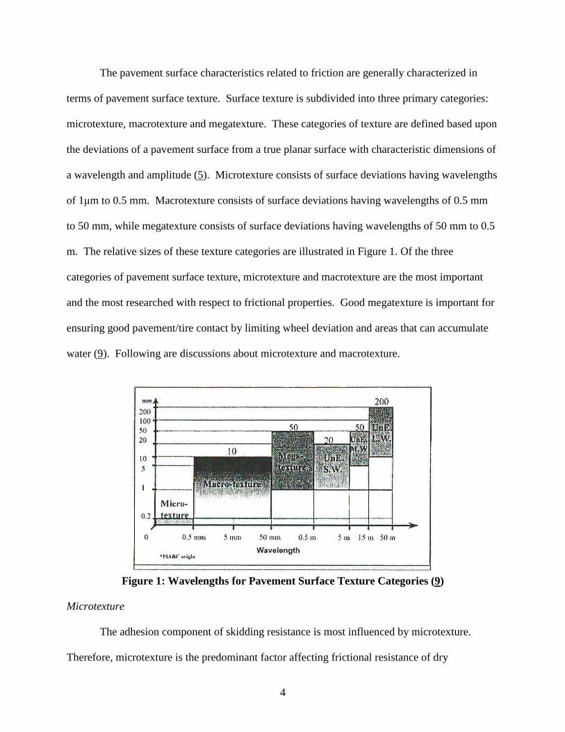
The pavement surface characteristics related to friction are generally characterized in
terms of pavement surface texture. Surface texture is subdivided into three primary categories:
microtexture, macrotexture and megatexture. These categories of texture are defined based upon
the deviations of a pavement surface from a true planar surface with characteristic dimensions of
a wavelength and amplitude (5). Microtexture consists of surface deviations having wavelengths
of 1μm to 0.5 mm. Macrotexture consists of surface deviations having wavelengths of 0.5 mm
to 50 mm, while megatexture consists of surface deviations having wavelengths of 50 mm to 0.5
m. The relative sizes of these texture categories are illustrated in Figure 1. Of the three
categories of pavement surface texture, microtexture and macrotexture are the most important
and the most researched with respect to frictional properties. Good megatexture is important for
ensuring good pavement/tire contact by limiting wheel deviation and areas that can accumulate
water (9). Following are discussions about microtexture and macrotexture.
Figure 1: Wavelengths for Pavement Surface Texture Categories (9)
Microtexture
The adhesion component of skidding resistance is most influenced by microtexture.
Therefore, microtexture is the predominant factor affecting frictional resistance of dry

5
pavements. However, microtexture also has benefits during wet conditions. The small
deviations in the pavement surface (microtexture) act to penetrate small films of water creating
more contact between the tire and the pavement surface. Microtexture is characterized as
polished to harsh as illustrated in Figure 2 (5). Generally, adequate microtexture is developed by
selection of the proper aggregate mineralogical type that has sufficient angularity, polish
resistance and surface texture.
Figure 3 illustrates the importance of aggregate type selection on microtexture. This
figure shows wet skid numbers for various HMA mixes from the 2000 National Center Asphalt
Technology (NCAT) Test Track (10). These mixes had gradations ranging from fine-graded
Superpave designed mixes to stone matrix asphalts (SMAs). Of these mixes, the SMAs have a
significant amount of macrotexture; however, when a high polish potential limestone was
utilized, the aggregate polished (lost microtexture) and resulted in a pavement with low skid
resistance even though the wearing surface had high macrotexture.
Because of the small wavelengths associated with microtexture, contaminants can affect
the ability of the microtexture to enhance frictional properties. Dust, debris, oil, etc. that collects
on a pavement surface can reduce the beneficial effects of microtexture.

6
Figure 2: General Scales of Microtexture and Macrotexture (2)
0.0
10.0
20.0
30.0
40.0
50.0
60.0
70.0
80.0
0.0 0.5 1.0 1.5 2.0 2.5 3.0 3.5 4.0 4.5 5.0 5.5 6.0 6.5 7.0 7.5
Millions of ESALs
Fri
cti
on
Nu
mb
er
(64
km
/hr)
Fine Slag/LMS
Coarse Slag/LMS
Dense Slag/LMS
SMA Slag/LMS
SMA LMS
Application of MaintenanceTreatment to Improve Friction
Figure 3: Skid Numbers for Various Mixes From the 2000 NCAT Test Track (10)

7
Macrotexture
The hysteresis component of skidding resistance is most influenced by the macrotexture
on the pavement surface (5). The magnitude of macrotexture is influenced by the shape, size,
angularity, density, distribution and arrangement of aggregates within the pavement surface
and/or the manipulation of a pavement surface (tining/grooving). An added benefit of increased
macrotexture, with respect to skidding resistance, is that the macrotexture provides channels for
water to drain off the pavement surface. This draining from the pavement surface helps prevent
large water films from building up between a tire and the pavement surface during a rain event,
which helps prevent hydroplaning. Hydroplaning is the separation between the tire and the
pavement surface due to the buildup of a water film thickness on the pavement surface.
Macrotexture is generally characterized as smooth to rough, as illustrated in Figure 2.
Different hot mix asphalt (HMA) types result in varying degrees of macrotexture. Figure 4
illustrates the influence of HMA gradation on macrotexture (10). This figure includes the
percent passing the 2.36mm (No. 8) sieve versus mean profile depth, which is a measure of
macrotexture. Increasing values of mean profile depth indicate increasing macrotexture. As
shown in the figure, as the percent passing the 2.36mm sieve decreases (or the gradation
becomes coarser) the mean profile depth increases. Porous friction courses show the highest
levels of mean profile depth within this figure.

8
0
10
20
30
40
50
60
0 0.2 0.4 0.6 0.8 1 1.2 1.4 1.6 1.8 2
Mean Texture Depth (mm)
Perc
en
tP
as
sin
g2.3
6m
m(N
o.
8)
Sie
ve
ARZ TRZ BRZ SMA PFC
Figure 4: Effect of Gradation Shape on Macrotexture (10)
Airfield Pavement Friction
Because of the high speeds associated with take-offs and landings, the frictional
characteristics of runways are of paramount importance. The Federal Aviation Administration
(FAA) has published guidelines and procedures for the design and construction of skid resistant
pavements. Advisory Circular (AC) 150/5320-12C, Measurement, Construction and
Maintenance of Skid-Resistant Airport Pavement Surfaces, provides recommendations for
runway friction. This AC is also referenced in Unified Facilities Criteria (UFC) 3-260-02,
Pavement Design for Airfields.

9
Within AC 150/5320-12C, there is discussion on how the FAA’s recommendations for
runway pavement surfaces were developed. Based upon various research studies conducted at
Langley Research Center, the FAA Technical Center, and the Naval Air Engineering Center,
pavement grooving was identified as a method of providing safe pavement surfaces for aircraft
operations during wet weather. Subsequent research conducted in the United Kingdom and US
showed that porous friction courses also achieve skid resistant pavement surfaces. For both
civilian and military airfields, grooving dense-graded HMA wearing layers or placing a porous
friction course are the predominant methods for providing safe wearing surfaces on runways.
However, the FAA recommends within AC 150/5320-12C that porous friction courses not be
constructed on airport runways that have more than 91 turboject arrivals per day per runway end.
Porous Friction Courses
The term porous friction course (PFC), or open-graded friction course (OGFC), in the US
is used to describe an HMA having an open aggregate grading that is used as a wearing course
on airfield and highway pavements. The airfield pavement community utilizes the term PFC
while the highway industry generally uses the OGFC term. Within the US, OGFCs evolved
during the 1930’s through experimentation with plant mix seal coats. In the 1970’s, the Federal
Highway Administration (FHWA) initiated a program to improve the frictional resistance of the
nation’s roadways (11). The plant mix seal coats were one of the tools an agency could use to
improve frictional resistance and, thus, gained popularity. In 1974, the FHWA published a mix
design procedure for OGFC. The procedure entailed an aggregate gradation requirement, a
surface capacity of coarse aggregate, determination of fine aggregate content, determination of
optimum mixing temperature and resistance of the designed mixture to moisture. Open-graded

10
friction course mixtures designed in accordance to the FHWA procedure were successful at
performing their intended function: removing water from the pavement surface and improving
wet weather frictional resistance.
Also during the 1970’s, the Waterway’s Experiment Station evaluated PFCs for airfield
pavements. This evaluation occurred because of hydroplaning problems (12) on airfield
runways.
Since the 1970’s, some significant improvements have been developed for PFCs, namely
the use of modified asphalt binders to improve durability and the incorporation of fibers to
prevent draindown. Additionally, various types of PFCs are commonly used in the U.S. Some
agencies specify PFCs having gradations similar to those recommended by the FHWA in the
1970’s and 1980’s. Some agencies have adopted coarser gradations (generally called permeable
friction courses, new-generation OGFC, or Porous European Mix) that provide higher air void
contents and, thus, more capacity to drain water from the pavement surface. Other agencies
construct an asphalt rubber friction course which utilizes a very open gradation; yet, a high
percentage of asphalt rubber binder is also used. These asphalt rubber friction courses do not
provide the permeability of other PFCs but provide high macrotexture for skid resistance as well
as reduction in noise levels at the tire/pavement interface.
PROBLEM STATEMENT
Porous friction courses, or OGFCs, have been used within the US since the 1930’s.
When placed as a wearing surface, these mixes have proven an effective method for improving
the frictional characteristics of pavements, especially in wet weather. Porous friction courses
improve wet weather skid resistance because of the open aggregate grading. This open gradation

11
results in a significant amount of macrotexture at the pavement surface. Additionally, the open
gradation with minimal fines results in water being able to infiltrate into the PFC layer and flow
laterally through the PFC layer to the pavement edge. Without the water on the pavement
surface, hydroplaning potential is greatly reduced.
Even though PFCs have been around many, many years, the performance of these mix
types has been mixed. There have been reports of rapid and catastrophic occurrences of raveling
within PFC layers. Any raveling that occurs will result in potential FOD. Also, there have been
reports of PFC wearing surfaces tearing at locations where high speed turns or locked wheel
turns take place.
Because of the safety benefits associated with PFCs, the highway industry has conducted
a significant amount of research on OGFCs over the last 10 to 15 years. Improvements have
specifically been made with regards to the methods for specifying materials and designing
mixtures. Methods and equipment for constructing PFCs have also improved. Whether the
intended use is for airfields or highways, maintenance of PFCs has always been a concern. This
concern is primarily due to the potential rapid failure from raveling. Another issue related to
maintenance is winter maintenance. Because of the open nature of PFCs, these layers have
different thermal properties compared to dense-graded HMA mixes.
In comparison to the highway industry, little work on the use of PFCs for airfield
pavements has been conducted in the last 10 to 15 years. Therefore, there is a need to evaluate
the current state of practice on the use of PFCs. Information obtained should be used to provide
guidance for the use of PFCs on airfields and to identify potential improvements for using PFC
wearing layers.

12
OBJECTIVES
As stated in the project statement, the objective of this study was to develop technical
guidance and direction to improve the performance of PFC mixtures on airfield pavements. This
guidance was to consider but not be limited to the following:
1) Performance history of PFC on airfield pavements;
2) PFC mix design requirements and qualities and characteristics of
component materials;
3) Construction requirements and limitations;
4) Effect of temperatures and other climatic conditions, especially durability under
freeze-thaw conditions, on construction and performance of PFC;
5) Existing surface preparation requirements;
6) Skid resistance characteristics of PFC;
7) Service life and maintenance of PFC;
8) Airfield pavement maintenance, including removal of aircraft tire rubber from the
pavement surface;
9) Performance of PFC considering airfield classifications and type of
aircraft using the facility; and
10) Compare and contrast design and performance of PFC use on highways and
airfields.

13
RESEARCH APPROACH
In order to accomplish the project objectives, a total of six tasks were conducted. The
following sections describe the activities conducted during each task.
Task 1 – Review Performance History of PFC/OGFC at Airports
Porous friction course has been placed on numerous civil and military airfields. During
Task 1, the researchers contacted and discussed the performance of PFC layers with airfield
pavement engineers. The various civil and military airfield personnel were interviewed to
determine:
1. Specific concerns about the use of PFC on airfield pavements.
2. Specific areas that have been problematic for PFC.
3. Typical maintenance activities (general and winter) for PFC and their effectiveness.
4. Typical life expectancy for PFC layers.
5. Type aircraft using the facility; airfield classification; and number of operations.
In essence, there are six primary issues that must be addressed: materials and design,
production/construction, maintenance, rehabilitation, advantages/disadvantages, and
performance. These six items are all related to how a PFC layer performs.
Task 2 – Identify Recent Improvements in PFC/OGFC
Within recent years, there has been a significant amount of research conducted on PFC
mixes. Most of this research has been applied to highway usage; however, this research was
very relevant to this project. Therefore, a literature review was conducted to determine the
current state of practice with regards to PFC. Of particular interest within this task were

14
improvements that could potentially increase life expectancy, minimize maintenance, maximize
the benefits and minimize the disadvantages of PFC.
Task 3 – Evaluate Recent Improvements
Based upon the results of Tasks 1 and 2, the research team evaluated each of the potential
improvements identified to provide an assessment of these improvements for future use on
airfield pavements. Potential improvements in all six areas identified in Task 2 were evaluated.
Task 4 – Develop Revised Draft Specifications and FAA Engineering Brief
Results from Tasks 1 through 3 were used to develop guidance on the design, production,
construction, maintenance and rehabilitation of PFCs. Additionally, a draft FAA Engineering
Brief was developed on recommendations for future use of PFC for airfield pavements.
Task 5 – Recommend Additional Work
Tasks 1, 2 and 3 identified current limitations, possible improvements to remedy the
limitations and an evaluation of the improvements. For limitations in which solutions could not
be identified, additional work was recommended. The recommended additional work
encompassed materials and design, production/construction, maintenance, rehabilitation and
performance.
Task 6 – Deliver Final Report
The final task was to submit a draft final report. The draft final report was compiled
according to the guidelines established by the AAPTP and presents a clear and concise summary
of the findings and conclusions generated from Tasks 1 through 5.

15
REPORT ORGANIZATION
The first chapter of this report provides a brief overview of PFCs, the project objectives
and research approach. Chapter 2 discusses the advantages and disadvantages on the use of
PFCs for airfield pavements. The advantages and disadvantages are provided at the beginning of
this report because the subsequent chapters provide discussion on methods of maximizing the
advantages while minimizing the disadvantages. The third chapter provides discussion and
guidance on the design of PFC mixtures along with material requirements. Chapter 4 discusses
the production and construction of PFCs and Chapter 5 discusses the maintenance and
rehabilitation of PFC layers. Within Chapters 2 through 5, the current state of practice for each
topic is provided as well as recent improvements. Where applicable, recommendations were
made for needed future research. Chapter 6 presents conclusions and recommendations derived
from the results of this research project, while the final chapter presents the references utilized
during conduct of this research. A draft FAA Engineering Brief that provides recommendations
for future use of PFC for airfield pavements was also developed.

16
CHAPTER 2Advantages and Disadvantages of PFCs on Airfield Pavements
INTRODUCTION
This chapter discusses the advantages and disadvantages of using PFC on airfield
pavements. Ideally, the results of this project will maximize the advantages of using PFC on
airfield pavements while minimizing any disadvantages. The literature indicates a number of
advantages that can be realized with the use of PFCs as a wearing layer. For the most part, the
benefits are based upon the ability of the PFC layer to drain water from the pavement surface.
Lefebvre (13) states that the benefits of PFCs can be categorized based upon three general areas:
safety, smoothness and environmental. The primary advantages related to safety are the
reduction in hydroplaning potential and improvement in wet weather friction. Porous friction
courses generally are smoother than dense-graded HMA layers which helps prevent directional
control problems for aircraft and improves fuel economy for vehicles. The environmental
benefits cited by Lefebvre (13) are not specifically related to airfield pavements and include
reduction in tire/pavement noise levels and improved fuel economy.
The primary disadvantages discussed in the literature were the increased cost and the
differences in winter maintenance practices compared to dense-graded HMA. Another perceived
disadvantage is that PFCs have been susceptible to rapid deterioration due to raveling.
ADVANTAGES OF USING PFCS ON AIRFIELD PAVEMENTS
Benefits of PFC related to safety include reduced potential for hydroplaning, improved
skid resistance (especially during wet weather), and reduced light reflection. Reduction in light
reflection is more applicable to highways because of the angle at which drivers view a pavement

17
surface. Hydroplaning occurs when a layer of water builds up between a tire and the pavement
surface (13). This layer of water breaks the contact between the tire and road (13, 14). When
this occurs, the aircraft will not respond to braking or turning. There are two aspects of PFCs
that help prevent the occurrence of hydroplaning. First, because the water drains from the
pavement surface into the PFC layer, the film of water is not available to break the bond between
the tire and pavement surface (12). The second aspect is the macrotexture provided at the
pavement surface by PFC layers. Even when clogged, PFCs provide a significant amount of
macrotexture. This macrotexture provides small channels for water to be dissipated as a tire
crosses over the pavement (5). Therefore, in wet weather conditions, the skid resistance of PFC
wearing layers is generally very good.
Many, many references mention that the use of PFCs as a wearing layer will improve
frictional properties, especially during wet weather. Similar to how PFCs reduce the potential
for hydroplaning, the ability to drain water from the pavement surface and the relatively high
macrotexture of PFCs also improve wet weather friction. Kandhal (15) cited a number of
references in his synthesis on OGFCs describing research conducted in the U.S., Canada and
Europe that showed the improved wet pavement frictional properties of PFCs. Much of the
research dealt with comparing the speed gradient (or friction gradient) encountered on PFC
layers. A frictional speed gradient can be defined as the rate of decrease in the friction number
per unit increase in speed. With low speed gradients, the pavement surface maintains its
frictional properties even at high speeds, which is vital on airfield runways. Therefore, low
frictional speed gradients are desirable. Table 2 presents data from a Pennsylvania Department of
Transportation project that showed a decreased frictional speed gradient for PFC layers. Similar

18
work in Oregon and Louisiana presented by Kandhal (15) also showed decreased friction
gradients for PFCs compared to dense-graded layers.
Table 2: Friction Data from Pennsylvania (excerpt from 15)Friction NumberMix
Type 30 mph 40 mphFrictionGradient
OGFC (gravel) 74 73 0.10OGFC (dolomite) 71 70 0.10Dense-graded HMA (gravel) 68 60 0.80Dense-graded HMA (dolomite) 65 57 0.80
Isenring et al (16) also conducted friction testing on 17 different PFC test sections at
different speeds including 40, 60, 80, and 100 kph (25, 37, 50 and 62 mph). Friction
measurements were made using the PIARC skid tester and a ribbed tire. Results showed that
PFC pavement surfaces had much higher coefficients of friction at higher speeds than typical
dense-graded surfaces. Similar to the referenced literature by Kandhal (15), the frictional speed
gradients for PFC surfaces were lower than for typical dense-graded layers.
Bennert et al (17) presented the results of wet skid tests on various wearing surfaces,
including PFCs. The skid measurements were made in accordance with ASTM E274-97,
Standard Test Method for Skid Resistance of Paved Surfaces Using a Full-Scale Tire. A test
speed of 64 kph (40 mph) was utilized using a ribbed-tire on the skid trailer. A total of 19
different pavement sections were tested. Included within the evaluation were asphalt rubber
OGFC, modified OGFC, Novachip, stone matrix asphalt, microsurface, Superpave designed
dense-graded HMA and Portland cement concrete. Table 3 presents the results of testing on the
19 test sections. Based upon the results, the asphalt rubber OGFC had the highest frictional
resistance of the thin lift wearing layers followed by the microsurfacing and MOGFC. The PFC

19
layers (AR OGFC and MOGFC) tested did provide higher wet-skid numbers than Novachip and
the SMA surfaces.
Table 3: Wet-Skid Numbers for Various Pavement Surfact Types (excerpt from 17)
Surface Type AgeWet-Skid Number
(SN40)Avg. Wet-Skid Number
(SN40) per SurfaceAR-OGFC 9 47.8AR-OGFC 10 55.9
51.9
MOGFC 1 47.9MOGFC 4 44.8MOGFC 2 51.2
48.0
Novachip 3 45.4Novachip 8 45.7
45.6
9.5 mm SMA 7 42.512.5 mm SMA 9 42.0
42.3
MS Type 3 1 49.6MS Type 3 1 49.1
49.4
12.5 mm SP 10 51.812.5 mm SP 4 54.3
53.1
PCC (no finish) 44 38.6PCC (no finish) 39 39.1PCC (no finish) 48 41.4
39.7
PCC (Trans. tined) 14 57.2PCC (Trans. tined) 14 55.8
56.5
PCC (Diamond Grind) 14 54.6 54.6AR-OGFC = asphalt rubber open-graded friction courseMOGFC = modified asphalt binder open-graded friction courseSMA = stone matrix asphalt MS = microsurfacingSP = Superpave PCC = Portland cement concrete
Recent work in the US by McDaniel and Thornton (18) has also shown that PFCs provide
relatively more macrotexture and higher International Friction Index (IFI) values than other
HMA wearing layers. Tables 4 and 5 present macrotexture and friction measurement data for
three test sections in Indiana, respectively. Pavement surfaces included within the research were
PFC, stone matrix asphalt, and dense-graded HMA.

20
Table 4: Results of Surface Texture Measurement from McDaniel and Thornton (18)
MixMean Profile Depth, mm
(Standard Deviation)PFC 1.37 (0.13)SMA 1.17 (0.14)HMA 0.30 (0.05)
Table 5: Results of Friction Measurement from McDaniel and Thornton (18)Average Dynamic Friction Tester (DFT) Number
(Standard Deviation)Mix20 kph 40 kph 60 kph
InternationalFriction Index
(F60)PFC 0.51 (0.03) 0.45 (0.03) 0.42 (0.03) 0.36SMA 0.37 (0.01) 0.31 (0.01) 0.29 (0.01) 0.28HMA 0.52 (0.01) 0.47 (0.01) 0.44 (0.01) 0.19
McDaniel and Thornton (18) indicated that the PFC and SMA wearing layers showed
significantly more macrotexture (reported as mean profile depth) than did the dense-graded
HMA (Table 4). The PFC layer did provide the highest average mean profile depth
measurement. Variability in measured mean profile depths was also found to be higher for the
PFC and SMA layers compared to the dense-graded surface. The authors indicated that this was
expected since the PFC and SMA mixes have gap- or open-graded aggregate structures.
McDaniel and Thornton (18) reported results of dynamic friction measurements made
with the Dynamic Friction Tester (Table 5). Based upon the raw friction numbers, the PFC and
dense-graded surfaces were comparable whereas the SMA surface showed the lowest values.
The authors also converted the mean profile depth and friction number data into the IFI. In terms
of IFI, the PFC showed the highest friction followed by the SMA and dense-graded surface.
A number of references indicate that the use of PFC wearing layers improves
smoothness; however, very little specific research was encountered that provided relative
improvements in smoothness when PFCs are utilized. Bennert et al (17) did compare the results
of ride quality measurements for a number of highway pavement surfaces in New Jersey

21
including: asphalt rubber OGFCs, modified OGFCs, Novachip, stone matrix asphalt,
microsurfacing and three types of rigid pavement surfaces (transverse tined, diamond grind and
no finish). Table 6 presents results of testing related to ride quality by Bennert et al. Two
measures of ride quality are provided within this table. The Ride Quality Index (RQI) was
measured using an ARAN vehicle. Previous studies in New Jersey cited by Bennert et al (17)
developed correlations between the ARAN van and user’s perceptions to ride quality. The RQI
is based upon a scale between 0 and 5, with an RQI of 5 being the “smoothest” ride according to
user’s perception. Results from the ARAN van were also used to determine the International
Roughness Index (IRI) for each of the pavements. According to the IRI definition and scale,
lower values of IRI are desirable.
Table 6: Results of Ride Quality Measurements for Various Pavement Surfaces (17)
Surface Type Age RQI valueRQI
RatingIRI
(inch/mile)Avg. IRI perSurface Type
AR-OGFC 9 3.54 Good 121AR-OGFC 10 4.34 V. Good 82
102
MOGFC 1 4.14 V. Good 90MOGFC 4 4.05 V. Good 68MOGFC 2 4.08 V. Good 113
90
Novachip 3 4.47 V. Good 65Novachip 8 3.51 Good 123
94
9.5 mm SMA 7 4.10 V. Good 8412.5 mm SMA 9 3.72 Good 194
139
MS Type 3 1 3.79 Good 108MS Type 3 1 4.02 V. Good 111
110
12.5 mm SP 10 4.15 V. Good 5612.5 mm SP 4 4.31 V. Good 74
65
PCC (no finish) 44 3.39 Good 178PCC (no finish) 39 3.13 Good 206PCC (no finish) 48 3.42 Good 137
174
PCC (Trans. tined) 14 2.66 Fair 274PCC (Trans. tined) 14 2.54 Fair 295
285
PCC (DiamondGrind)
14 4.21 V. Good 7575
AR-OGFC = asphalt rubber open-graded friction courseMOGFC = modified asphalt binder open-graded friction courseSMA = stone matrix asphalt MS = microsurfacingSP = Superpave PCC = Portland cement concrete

22
Bennert et al (17) state that based upon the RQI data it was difficult to determine the
“best” pavement surface because of so many variables (most notably age). However, for the thin
lift HMA mixes included in the study (MOGFC, AR-OGFC, Novachip and microsurfacing), the
PFC mixes did have the highest average RQI values. Similar results were obtained using the IRI
measurements.
DISADVANTAGES OF USING PFCS ON AIRFIELD PAVEMENTS
Probably the biggest deterrent cited for using PFC layers is freezing weather. Porous
friction courses have a lower coefficient of thermal conductivity than dense-graded HMA. This
means that the temperature of the pavement surface drops below freezing sooner than dense-
graded HMA, and stays below freezing longer (19).
The primary concern then becomes a winter maintenance issue, especially winter icing.
Winter maintenance is different for porous pavements because of the “…different temperature
behavior for porous asphalt, and because of difficulty in maintaining a sufficient salt level at the
point of contact between tire and pavement”(20).
Moore et al mention three conditions under which open-graded mix in Oregon is not
recommended for use (20, 21). These are: 1) low volume roads with ADT of less than 1,000; 2)
curbed areas or areas requiring handwork; and, 3) heavily snow plowed areas where steel plow
blades are used. For airfield pavements, only the snowplow issue is of importance. As a result
of snowplow damage, Oregon’s Class F mix is no longer recommended in areas where plowing
is frequent (20, 21, 22). The snowplows can cause raveling and gouging resulting in a higher
rate of surface deterioration.

23
Two papers gave a list of disadvantages for using PFCs. Lefebvre in his paper (13) listed
several disadvantages. First, Lefebvre stated that PFCs generally cost more than dense-graded
layers as a result of requiring high quality, polish resistant aggregates and modified asphalt
binders. Also, pavement markings have to be adapted for PFCs. Because of the openness of
PFCs, some pavement marking materials will infiltrate into the layer during placement. Special
impervious layers specifically placed below PFCs can also increase construction costs. Another
disadvantage of using PFCs is the relatively shorter economic life. Most references state that
PFCs last 8 to 12 years on highways, while dense-graded layers will last 10 to15 years. The 8 to
12 year expected lift on highways matches the experiences of most airfield pavement engineers
interviewed. Finally, Lefebvre stated that maintenance is generally more expensive, especially
winter maintenance. In another paper, Bolzan et al (23) mention that disadvantages include
increased costs; relatively low structural strength due to its high void content; possibly shorter
service life; complications to winter maintenance procedures; maintenance patching difficulties;
susceptibility to high stress sites; and requirement of minimizing the drainage path length to
allow water passing through the layer to enter the drainage system.
Kandhal (15) provides a number of situations where PFC should not be used. Porous
friction courses should likely not be used on projects that include long haul distances. Long haul
distances increase the potential for draindown and/or cooling of the mix. Oregon restricts haul
distance for OGFC to 56km (35 miles) (21). Porous friction courses should not be used in
inlays. Porous friction courses should be free draining at the pavement edge; therefore, they
should not be used as an inlay. Handwork is difficult with PFC mixes. Therefore, projects that
include a lot of handwork should probably not include PFC. Kandhal (15) noted that PFC should
not be used in snow zones where extensive snow plowing is required. Porous friction courses

24
may ravel and shove in some critical pavement locations with heavy turning movements, and
other adverse geometric locations. The final limitation noted by Kandhal (15) has to do with
underlying layers. Porous friction courses should not be placed on a permeable pavement layer
as water can infiltrate through the PFC into a permeable underlying layer causing moisture
damage within the underlying layer.
After construction, PFCs generally have a lower friction value when braking with locked
wheels. When the wheels lock, they begin to melt the thin layer of binder coating the aggregates
on the pavement surface, which creates a slippery surface. This is only true when the wheels are
locked. This layer of binder is worn off after approximately 3 to 6 months and friction values
increase (19).
During the life of PFC layers, dirt, debris, winter maintenance products and other
materials can enter the void structure. These contaminants will lead to clogging of the layer and
results in the layer not being able to remove water from the pavement surface. It should be
stated; however, that clogged PFCs still maintain their frictional properties because of the high
amounts of macrotexture. Another potential problem with debris within the voids of the PFC
layers is that the debris can retain moisture after the rain event leading to an increased potential
for moisture damage.
SUMMARY
The advantages and disadvantages of using PFCs are both primarily related to the
openness of these mixes. The open nature of PFCs allows water to infiltrate into the layer. Since
the water infiltrates into the layer, water films will not develop. Water films on the pavement
surface increase the potential for hydroplaning. Hydroplaning can make aircraft lose directional
control and the ability to brake.

25
Because of the open gradation inherent in PFCs, these mix types have a significant
amount of surface texture in the wave length and amplitude range of macrotexture. High levels
of macrotexture combined with the selection of polish resistant aggregates (to provide
microtexture) result in improved frictional properties compared to typical dense-graded HMA
layers, especially in wet weather.
A benefit that is not specifically related to the ability of PFCs to remove water from the
pavement surface is the improved smoothness compared to typical HMA mixes. The improved
smoothness is likely related to the constructability of PFC mixes. As will be discussed in
Chapter 4, the goal of PFC compaction is simply to seat the aggregates, not densify the mix to an
impermeable compaction level. Therefore, only static-steel wheel rollers are used for PFCs with
each roller making relatively few passes. These construction related factors are likely the reason
for improved smoothness with PFCs. At the typical high speeds encountered on airfield
runways, the improved smoothness will reduce the potential for aircraft structural damage and
component fatigue; reduce the potential for aircraft prematurely becoming airborne; improve the
contact between tires and the pavement surface; minimize aircraft vibrations; and provide a more
comfortable ride for passengers.
The primary disadvantages of using PFC are winter maintenance, rapid raveling of the
layer, and moisture damage in underlying layers. Because of the open nature of PFCs, these
layers have different thermal properties than typical dense-graded HMA layers. Porous friction
course layers will generally reach a freezing temperature prior to dense-graded mixes and stay at
a freezing temperature longer. For this reason, PFC layers generally require a different winter
maintenance regime than other pavement surface types.

26
The primary distress that has been associated with the use of PFCs is raveling. Within
the highway industry the occurrence and severity of raveling caused a moratorium by some
agencies on the use of PFCs within the 1980’s. During the interviews with various airfield
pavement engineers, raveling was discussed as a problem with some PFC layers. Rapid
deterioration of PFC layers due to raveling was identified as a disadvantage. Raveling of any
kind increases the potential for FOD.
Another potential problem identified in several of the airfield pavement engineer
interviews was stripping in underlying layers. Stripping in underlying layers has also been noted
in highway uses. It is unlikely that changes can be made to the design and construction of PFC
mixes to minimize the potential for stripping in underlying layers; however, modifications can
likely be made to the design and construction of underlying layers to minimize the potential for
stripping.

27
CHAPTER 3Design of PFC Mixes for Airfield Pavements
INTRODUCTION
One of the highlighted areas of developing technical guidance and direction to improve
the performance of PFCs was mix design requirements. This section provides discussion on
current mix design methods for PFCs used on airfields, current mix design methods for OGFCs
for highways and recommendations for improvements to the current airfield mix design methods.
Current limitations in the design of PFC mixes are provided and, where needed, additional work
recommended in the final section of this chapter. A tentative mix design method for PFCs that is
based upon the recommended improvements is presented in Appendix A.
CURRENT AIRFIELD MIX DESIGN METHODS FOR PFC
The primary PFC mix design specifications utilized for airfield applications include Item
P-402 documented in FAA AC 150/5370-10B and the Department of Defense (DoD), Unified
Facilities Guide Specification (UFGS)-32 12 20 (formerly UFGS-02747). As with the design of
other HMA types, the design of PFC mixes outlined within these two specifications entails
several steps. The first step in the mix design process is to select acceptable materials. Next, the
materials must be blended to develop a design aggregate gradation. Optimum asphalt binder
content for the selected materials using the design gradation must next be determined. The final
step in the design is to evaluate the performance of the designed mix. Both specifications
evaluate performance with laboratory moisture susceptibility testing. The following sections
describe the current mix design procedures for PFCs used on airfields.

28
Materials Selection
Both mix design methods provide requirements for coarse aggregates, fine aggregates,
mineral fillers, asphalt binders and additives. Both methods define coarse aggregates as the
fraction of aggregate materials retained on the 4.75mm (No. 4) sieve. Fine aggregates are the
fraction passing through the 4.75mm (No. 4) sieve and retained on the 0.075mm (No. 200) sieve.
Mineral fillers are the aggregate fraction that passes through the 0.075mm (No. 200) sieve.
Both methods provide requirements on the shape, angularity, toughness and soundness of
coarse aggregates. Particle shape is controlled within both specifications using ASTM D4791,
Standard Test Method for Flat Particles, Elongated Particles, or Flat and Elongated Particles in
Coarse Aggregate. However, the two specifications do not have the same requirements. Item P-
402 requires that the coarse aggregate fraction contain no more than 8 percent, by mass, of flat or
elongated particles, while UFGS-32 12 20 states that the “… quantity of flat and elongated
particles in any sieve size shall not exceed 8 percent, by mass.” The differences in the
requirements include the measure of particle shape as well as the material that is tested.
ASTM D4791 compares the dimensions of aggregate particles in order to define a
measure of shape. To conduct this test, aggregate particles are measured with a proportional
caliper using a specified ratio. To evaluate flat particles, the proportional caliper is used to
compare a particle’s thickness to width. Width is defined as the maximum dimension
perpendicular to the particle’s length; where, length is defined as the maximum dimension of the
particle. Thickness is defined as the maximum dimension perpendicular to both the length and
width. Elongated particles are defined as those having a ratio of length to width greater than the
specified ratio. For evaluating flat and elongated particles, the length of each particle is
compared to its thickness. Determination of the percent flat and elongated particles, as required

29
in UFGS-32 12 20, entails determining the percentage of aggregate particles that fail the flat and
elongated definition based on the total mass of the aggregate sample. Determination of the
percentage of flat or elongated particles, as required in Item P-402, entails determining the
combined percentage of aggregate particles that fail either the flat particle or the elongated
particle definition based on the total mass of the aggregate sample. Item P-402 references
ASTM D693, Standard Specification for Crushed Aggregate for Macadam Pavements, which
states that the specified ratio for which aggregates are to be evaluated during ASTM D4791 is
5:1. UFGS-32 12 20 does not state the specified ratio for which aggregates are to be compared.
As stated above, another difference between the two mix design methods is the material
to be tested. ASTM D4791 calls for the testing of the combined particles larger than the 9.5mm
(3/8 in.) sieve. However, UFGS-32 12 20 states “… any sieve size shall not exceed 8 percent…”
when referencing coarse aggregates. Though this may be a misinterpretation, the wording of
UFGS-32 12 20 indicates that material retained on each sieve should be tested.
Neither Item P-402 or UFGS-32 12 20 reference a particular test method for evaluating
the angularity of coarse aggregates; however both have a requirement that the coarse aggregate
must contain at least 75 percent , by mass, of crushed particles having two or more fractured
faces. Item P-402 further requires that 100 percent of the coarse aggregates have at least one
fractured face. Though neither method references a particular test method, both state that for a
face to be considered fractured, it must be equal to at least 75 percent of the smallest mid-
sectional area of the particle. Similar to the particle shape testing, the wording within UFGS-32
12 20 indicates that the fractured face count should be determined for each size fraction larger
than the 4.75mm (No. 4) sieve stating “… gravel retained on the 4.75mm (No. 4 sieve) and each

30
coarser sieve…” Similar wording can be found in the Corps of Engineers test method CRD-C
171, Standard Test Method of Determining Percentage of Crushed Particles in Aggregate.
UFGS-32 12 20 also has a requirement for angularity to be applied to fine aggregates.
The fractured face count of aggregates passing the 4.75mm (No. 4) sieve and retained on the
0.60mm (No. 30) sieve are to be tested. Within this size fraction, 90 percent of the aggregate
particles must have two or more fractured faces. Additionally, UFGS-32 12 20 limits the amount
of natural sand to a maximum of 5 percent, by total mass of the aggregates. Item P-402 simply
states that the amount of natural sand to be added, if necessary, will be “… to produce mixtures
conforming to the requirements…” of Item P-402.
Both specifications utilize ASTM C131, Resistance to Abrasion of Small Size Coarse
Aggregates by Use of the Los Angeles Machine, to define aggregate toughness. Item P-402
limits the percent loss to a maximum of 30 percent, while UFGS-32 12 20 recommends an upper
limit of 25 percent for PFCs used on airfields.
ASTM C88, Soundness of Aggregates by Use of Sodium Sulfate or Magnesium Sulfate, is
required in both methods for defining the soundness of coarse aggregates. A maximum of 12
percent loss is required in both; however, Item P-402 states that sodium sulfate be used, while
UGFS-32 12 20 does not recommend whether sodium sulfate or magnesium sulfate be used
during testing.
Item P-402 provides requirements for the cleanliness of fine aggregates. The plasticity
index cannot be more than 6 and the liquid limit can not be more than 25 when tested in
accordance with ASTM D4318, Liquid Limit, Plastic Limit and Plasticity Index of Soils.

31
No specific requirements are listed in Item P-402 or UFGS-32 12 20 for fillers.
However, Item P-402 does state that fillers not naturally present within the aggregate shall meet
the requirements of ASTM D242, Mineral Fillers for Bituminous Paving Mixtures.
Asphalt binders used in PFC must be viscosity-graded according to Item P-402, while
both viscosity- and penetration-graded binders are allowable according to UFGS-32 12 20.
UFGS-32 12 20 states that “use of modified bituminous materials such as polymers, latex
rubbers, and reclaimed tire rubber should be considered for improving PFC pavement
performance.” Item P-402 requires the addition of synthetic rubber in the asphalt binder in an
amount not less than 2 percent. Table 7 presents requirements for asphalt binders listed within
Item P-402. An identical table is provided within UFGS-32 12 20 but is only provided as an
example.
Table 7: Asphalt Binder Requirements within Item P-402Property ASTM Min. Max.
Viscosity @ 140˚F, Poises D2171 1600 2400Viscosity @ 275˚F, cSt. D2170 325Flash Point, ˚F D92 450Ductility @ 77˚F (5 cm/min) cm D113 100Ductility @ 39.2˚F (5 cm/min) cm. D113 50Toughness, inch-pounds D5801 110Tenacity, inch-pounds D5801 75Thin Film Oven Test:Tests on ResidueViscosity @ 140˚F, Poises D2170 8000Ductility @ 77˚F (5 cm/min)cm D113 100Ductility @ 39.2˚F (5 cm/min)cm D113 25
The final material to be selected is additives. Additives include materials such as
antistripping agents, antifoaming agents and silicone. UFGS-32 12 20 states that these additives
can only be incorporated with approval. Item P-402 only mentions antistripping agents as an
additive and states that the additive “…be heat stable, shall not change the asphalt cement

32
viscosity beyond specifications, shall contain no harmful ingredients, shall be added in
recommended proportion by approved method and shall be a material approved by the
Department of Transportation in which the project is located.”
In summary, both Item P-402 and UFGS-32 12 20 provide requirements on the shape,
angularity, toughness and soundness of aggregates. Item P-402 also provides requirements for
the cleanliness of fine aggregates. Both also require viscosity-graded asphalt binders; however,
UFGS-32 12 20 also allows penetration-graded asphalt binders. In general, the material
requirements within the two mix design methods are similar. There are, however, some minor
differences in the material requirements.
Selection of Design Aggregate Gradation
Both Item P-402 and UFGS-32 12 20 contain two gradation bands for PFCs. Each has a
gradation band for a ¾ in. (19mm) maximum aggregate size gradation and a ½ in. (12.5mm)
maximum aggregate size gradation band. Tables 8 and 9 present the gradation requirements
contained within Item P-402 and UFGS-32 12 20, respectively. Figures 5 and 6 illustrate the
gradations by maximum aggregate size.
Table 8: Gradation Requirements for Porous Friction Courses - Item P-402Sieve, mm ¾ in. (19.0 mm)
maximum½ in. (12.5 mm)
maximum19.0 (¾ in.) 10012.5 (½ in.) 70-90 1009.5 (3/8 in.) 40-65 85-954.75 (No. 4) 15-25 30-452.36 (No. 8) 8-15 20-301.18 (No. 30) 5-9 9-170.075 (No. 200) 1-5 2-7
33
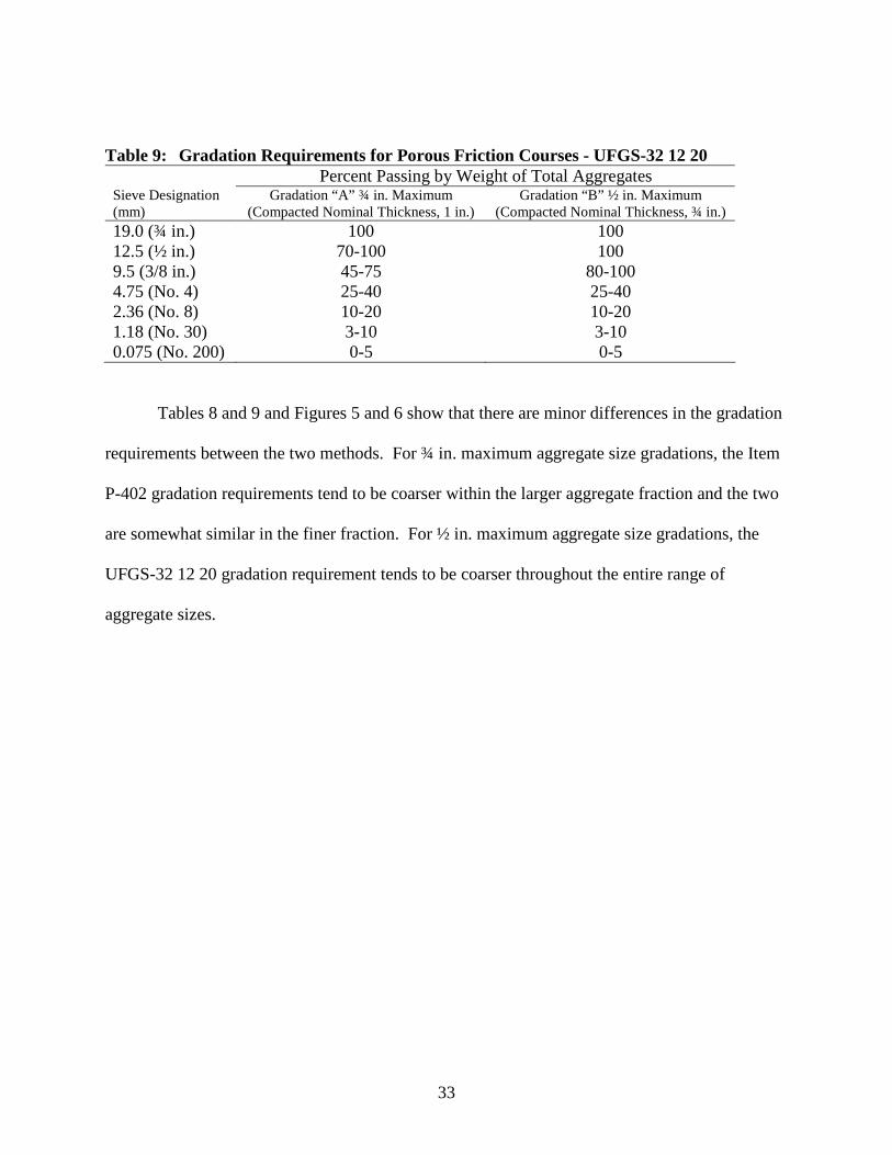
Table 9: Gradation Requirements for Porous Friction Courses - UFGS-32 12 20Percent Passing by Weight of Total Aggregates
Sieve Designation(mm)
Gradation “A” ¾ in. Maximum(Compacted Nominal Thickness, 1 in.)
Gradation “B” ½ in. Maximum(Compacted Nominal Thickness, ¾ in.)
19.0 (¾ in.) 100 10012.5 (½ in.) 70-100 1009.5 (3/8 in.) 45-75 80-1004.75 (No. 4) 25-40 25-402.36 (No. 8) 10-20 10-201.18 (No. 30) 3-10 3-100.075 (No. 200) 0-5 0-5
Tables 8 and 9 and Figures 5 and 6 show that there are minor differences in the gradation
requirements between the two methods. For ¾ in. maximum aggregate size gradations, the Item
P-402 gradation requirements tend to be coarser within the larger aggregate fraction and the two
are somewhat similar in the finer fraction. For ½ in. maximum aggregate size gradations, the
UFGS-32 12 20 gradation requirement tends to be coarser throughout the entire range of
aggregate sizes.

34
¾" Maximum Aggregate Size Gradations
0
10
20
30
40
50
60
70
80
90
100
Sieve Size
Perc
en
tP
assin
g
Item P-402
UFGS-32 12 20
¾ in.½ in.⅜ in.No. 4No. 8No. 30No.200
Figure 5: 3/4 in. Maximum Aggregate Size Gradations
½" Maximum Aggregate Size Gradations
0
10
20
30
40
50
60
70
80
90
100
Sieve Size
Perc
en
tP
assin
g
Item P-402
UFGS-32 12 20
¾ in.½ in.⅜ in.No. 4No. 8No. 30No.200
Figure 6: 1/2 in. Maximum Aggregate Size Gradations

35
Selection of Optimum Asphalt Binder Content
To determine the estimated optimum asphalt binder content, both methods utilize the
Centrifuge Kerosene Equivalent (CKE) method. Item P-402 references the Asphalt Institute’s
MS-2, Mix Design Method for Asphalt Concrete and Other Hot Mix Types (24), and UFGS-32
12 20 references the California Department of Transportations (CDT) Test 303, Method of Test
for Centrifuge Kerosene Equivalent and Approximate Bitumen Ratio, for conducting the CKE
method. The CKE test method provides a measure of aggregate surface area and the absorption
characteristics of the aggregates. For PFCs, the test is conducted on the coarse aggregate
fraction only. The test for PFCs entails placing the coarse aggregate fraction of the design blend
within a metal funnel. The metal funnel and aggregates are then submerged within a beaker
containing SAE No. 10 lubricating oil for 5 minutes at room temperature. Following the 5
minute soak, the funnel is removed from the beaker and allowed to drain for 2 minutes. Next,
the funnel and sample are drained an additional 15 minutes at a temperature of 60˚C (140˚F).
The difference in aggregate mass before and after is used to determine the percent oil retained.
The percent oil retained is then used to determine the Surface Constant (Kc) of the aggregates
using a graphical relationship between percent oil retained and Kc. Equation 1 presents the
relationship between estimated optimum asphalt binder content and Kc. The value determined
from Equation 1 is based upon the dry mass of aggregates and, therefore, must be converted to
the percent by total mass of mixture.
0.42 cKContentBinderOptimumEstimated Equation 1

36
Evaluation of Moisture Susceptibility
Item P-402 does not require testing of the designed mixture for moisture susceptibility;
however, UFGS-32 12 20 requires at least 95 percent retained coating. No test method is
provided within UFGS-32 120 20 for the percent retained coating. Based upon work by
Anderton (21), ASTM D1664, Test Method for Coating and Stripping of Bitumen-Aggregate
Mixtures, is used to determine the percent retained coating. The test method begins by coating
the aggregates with asphalt binder. After coating, the mixture is allowed to cool to room
temperature. Next, the mixture is covered with distilled water at room temperature and allowed
to sit for 16 to 18 hours. After this time period, the water covered sample is illuminated by a
shaded lamp and a visual observation is made of the aggregate surface area that remains coated
with asphalt binder. The test results are then reported as the percent aggregates with retained
coating. Anderton (25) indicates that this test identifies those mixes with extremely serious
stripping potential. Unfortunately, this test method was withdrawn by ASTM without
replacement in 1992.
DESIGN OF OGFCS USED FOR HIGHWAYS
Within the highway industry, open-graded friction course (OGFC) is a generic term to
describe a specialty type HMA. The term was coined because of the large fraction of coarse
aggregate and low percentages of mineral filler which created an open aggregate structure. In
actuality, there are a number of OGFC types that are used for highways. The primary difference
between the different OGFC types is the intended function of the mixture as a pavement layer.
Some OGFC mixtures are designed specifically to remove large amounts of water from the
pavement surface during rain events. This is accomplished by specifying very coarse aggregate

37
gradations and air void contents above 18 percent during mix design. Another type of OGFC is
specifically designed to reduce tire-pavement noise on urban highways. These OGFC types
generally have small maximum aggregate size gradations (though still open) and incorporate
high percentages of crumb-rubber modified asphalt binders. Air void contents within these
OGFC types are generally in the 12 to 15 percent range. Another type OGFC is one that was
recommended by the Federal Highway Administration (FHWA) approximately 20 years ago.
This type of OGFC also contains an open aggregate grading but air void contents are generally
around 15 percent. These types of OGFC were recommended specifically to improve frictional
properties. It should be stated, however, that all three OGFC types discussed above provide high
levels of macrotexture and, therefore, provide improved frictional properties compared to dense-
graded HMA layers.
The specific type of OGFC used by a highway agency is generally a direct response to
the performance issues that the agency faces. For instance, the Georgia Department of
Transportation utilizes an OGFC that is specifically designed to remove large volumes of water
from the pavement surface. This is in response to the large amount of rainfall that can be
encountered within the southeast US. These OGFC types also allow water to drain through the
layer over multiple lanes of traffic. Conversely, the Arizona Department of Transportation
utilizes the small maximum aggregate size gradation OGFC with crumb-rubber modified asphalt
binder near Phoenix. This is in direct response to high traffic noise levels as this OGFC type has
been shown to reduce tire/pavement noise.
The following sections describe the design of OGFC mixes for highway pavements.
Unfortunately, a number of the mix design methods used for highway pavements are recipe

38
methods. Therefore, the discussions are more general than the discussion on the two airfield
PFC mix design methods.
Material Properties
Aggregates used in OGFC mixtures should be tough enough to resist degradation due to
environmental effects and loading conditions and should provide frictional characteristics
sufficient to resist polishing of the aggregate surface. The 1990 FHWA Technical Advisory (26)
recommended that the coarse aggregate fraction be 100 percent crushed material. However, it is
recommended that the coarse aggregate fraction, defined as the percent retained on the 2.36 mm
(No. 8) sieve, have at least 75 percent of the particles, by mass, with at least two fractured faces
and 90 percent with one or more fractured faces. While several agencies in the United States
require 100 percent quarried material, virtually all European agencies require quarried aggregates
be used in OGFCs. South Africa does make provisions for gravel on low volume routes by
requiring only 90 percent with two or more fractured faces (27).
The Los Angeles Abrasion test is typically used to determine aggregate toughness.
However, there is a wide range in permissible values. British specifications limit the Los Angeles
Abrasion loss to a maximum of 12 percent. Other countries in Europe and South Africa have
similar requirements with a maximum abrasion loss of 25 percent (27). In contrast, the 1990
FHWA Technical Advisory recommended a maximum abrasion loss of 40 percent (26). It is
most likely that agencies have set specification limits dependent on the best quality of locally
available aggregates.
One of the most significant changes in production of OGFC mixtures has been the trend
toward use of polymer-modified asphalt in order to reduce binder draindown and improve

39
resistance to raveling. National Cooperative Highway Research Program (NCHRP) Synthesis
180 (28) published in 1992 barely mentioned the use of modified asphalt within OGFCs.
However, after the European Asphalt Study Tour in 1990, it was learned that the use of fiber and
polymer-modified binders were significantly improving the performance of SMA and OGFC
mixtures in Europe. NCHRP Synthesis 284 (27) completed in 2000 showed that in the period
from 1992 to 2000 there was more widespread usage of both fiber stabilizers and polymer-
modified asphalt in OGFCs.
Selection of Design Aggregate Gradation
There are typically four aggregate gradations that have been used for OGFC mixtures for
highway construction (Table 10). The 12.5 mm (1/2 inch) maximum aggregate size gradation
shown in Table 10 was recommended in a FHWA 1974 report (29) and in a subsequent 1990
Technical Advisory (22). This open-graded mixture provided benefits such as reduced
hydroplaning, increased surface friction, and reduced noise pollution. As traffic volumes grew
and roadways became wider, there was a movement toward coarser OGFC mixtures to increase
water drainage capacity across multiple lanes of traffic. This led to adoption of the porous
European mixtures such as the 19 mm (3/4 inch) maximum aggregate size OGFC shown in
Table 10. These mixtures are typically used on roadways with high traffic volumes and high
speeds such as interstate-type routes. Both Georgia and Alabama, for example, use a coarse
OGFC mixture as the final wearing surface layer on all their flexible pavement interstate
projects. Oregon is the only state agency to use the 25 mm (1 inch) maximum aggregate size
OGFC mixture on a regular basis. The final gradation shown within Table 10 is for a 9.5mm (3/8
in.) maximum aggregate size. This type of mixture is routinely used in the southwestern portion
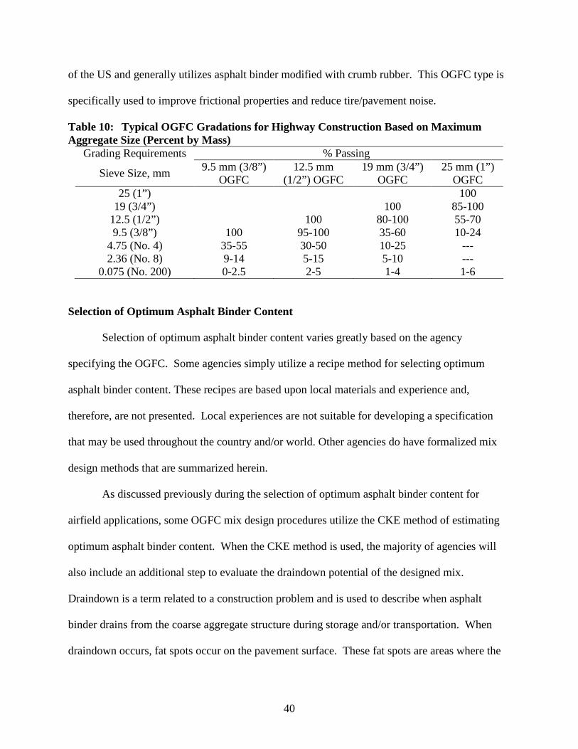
40
of the US and generally utilizes asphalt binder modified with crumb rubber. This OGFC type is
specifically used to improve frictional properties and reduce tire/pavement noise.
Table 10: Typical OGFC Gradations for Highway Construction Based on MaximumAggregate Size (Percent by Mass)
Grading Requirements % Passing
Sieve Size, mm9.5 mm (3/8”)
OGFC12.5 mm
(1/2”) OGFC19 mm (3/4”)
OGFC25 mm (1”)
OGFC25 (1”) 100
19 (3/4”) 100 85-10012.5 (1/2”) 100 80-100 55-709.5 (3/8”) 100 95-100 35-60 10-24
4.75 (No. 4) 35-55 30-50 10-25 ---2.36 (No. 8) 9-14 5-15 5-10 ---
0.075 (No. 200) 0-2.5 2-5 1-4 1-6
Selection of Optimum Asphalt Binder Content
Selection of optimum asphalt binder content varies greatly based on the agency
specifying the OGFC. Some agencies simply utilize a recipe method for selecting optimum
asphalt binder content. These recipes are based upon local materials and experience and,
therefore, are not presented. Local experiences are not suitable for developing a specification
that may be used throughout the country and/or world. Other agencies do have formalized mix
design methods that are summarized herein.
As discussed previously during the selection of optimum asphalt binder content for
airfield applications, some OGFC mix design procedures utilize the CKE method of estimating
optimum asphalt binder content. When the CKE method is used, the majority of agencies will
also include an additional step to evaluate the draindown potential of the designed mix.
Draindown is a term related to a construction problem and is used to describe when asphalt
binder drains from the coarse aggregate structure during storage and/or transportation. When
draindown occurs, fat spots occur on the pavement surface. These fat spots are areas where the

41
asphalt binder content is high and can result in a pavement surface with poor frictional
characteristics. Conversely, there will also be areas with low asphalt binder contents that will be
prone to raveling. The most common draindown potential test used with the CKE method of
selecting optimum asphalt binder content is the “pie-plate” method. This method entails placing
loose OGFC mixture into a pie plate. The mix and pie plate are then placed into an oven at a
specified temperature. After a specified time period, the loose mixture and pie plate are removed
from the oven. Draindown potential is evaluated by the amount of asphalt binder that drains
from the aggregate structure and adheres to the pie plate. The estimated optimum asphalt binder
content is then modified based upon results of the draindown testing. If draindown potential is
high, the optimum asphalt binder content is lowered, or the mixture is redesigned.
The most performance based mix design method currently used for highway OGFCs was
developed by NCAT in 2000 (30). This mix design procedure is for an OGFC that has been
called “new-generation” open-graded friction course which is an OGFC specifically designed to
remove large volumes of water from the pavement surface. Selection of optimum asphalt binder
content is based upon the results of laboratory performance tests.
Within the NCAT recommended mix design method, the selected design gradation is
combined with asphalt binder at three binder contents, in increments of 0.5 percent. A draindown
test is conducted for each asphalt binder content on loose mix at a temperature 15°C higher than
anticipated production temperature. The draindown test is different than the pie-plate method
described above. Loose mix is placed within a wire basket. The wire basket and loose mixture
are placed into a forced draft oven for one hour. Underneath the wire basket, a plate or container
is placed. At the conclusion of the test, the amount of asphalt binder that drains from the loose
mixture through the wire mesh basket onto the plate/container is measured. Draindown is

42
expressed as the percentage of asphalt binder draining from the loose mixture based on the
original total mass of the sample. Mixture at the three asphalt binder contents is also compacted
using 50 gyrations of a Superpave gyratory compactor to evaluate air void contents. The
Cantabro Abrasion test is also conducted on laboratory compacted samples using unaged and
aged (7 days @ 60°C) samples in order to evaluate durability. The Cantabro Abrasion test is
conducted by placing a single compacted sample of OGFC into a Los Angeles Abrasion drum
without the charge of steel spheres. The drum is then rotated 300 revolutions at room
temperature. At the conclusion of the 300 revolutions, the sample is removed and the abrasion
loss is reported as the percent material lost during the test based upon the original mass of the
sample. Optimum asphalt binder content is one that meets all of the following criteria.
1. Air Voids. A minimum of 18 percent is acceptable, although higher values are more
desirable. The higher the air voids are the more permeable the OGFC.
2. Abrasion Loss on Unaged Specimens. The abrasion loss from the Cantabro test should
not exceed 20 percent.
3. Abrasion Loss on Aged Specimens. The abrasion loss from the Cantabro test should not
exceed 30 percent.
4. Draindown. The maximum permissible draindown should not exceed 0.3 percent by total
mixture mass.
Evaluation of Moisture Susceptibility
There are two tests that are prevalent for evaluating the moisture susceptibility of OGFC
mixtures. The first is using the tensile strength ratio concept. Within this method, samples of
OGFC are compacted in the laboratory. A subset of the samples is subjected to moisture

43
conditioning. Several mix design methods include at least one freeze/thaw cycle within the
conditioning process. Mallick et al (30) recommended five freeze/thaw cycles for conditioning
specimens. After conditioning one subset of samples, the indirect tensile test is conducted on
both the conditioned subset and the unconditioned subset. Tensile strength ratios are then
developed by dividing the tensile strength of the conditioned subset by the unconditioned subset.
The other prevalent method for evaluating moisture damage is the boil method. This
method entails boiling loose OGFC mixture in water. After the prescribed time, the loose
mixture is visually evaluated to determine the percentage of aggregates in which the asphalt
binder has separated from the aggregates.
POTENTIAL IMPROVEMENTS TO MIX DESIGN FOR AIRFIELD PAVEMENTS
In order to make recommendations for improving the design of PFC mixes for airfields,
some discussion is needed to describe the desirable properties for PFC pavement layers.
According to AC 150/5320-12C, Measurement, Construction, and Maintenance of Skid-
Resistant Airport Pavement Surfaces, PFC pavements are one method for improving runway
pavement skid resistance and mitigating hydroplaning. Therefore, the desirable properties of a
PFC for airfield applications are a wearing layer that provides high frictional resistance and
minimizes the potential for hydroplaning without increasing the potential for FOD. Porous
friction course pavements are not utilized on airport runways with over 91 turbojet arrivals per
runway end per day. Since some larger aircraft will operate on the PFC, the mixture should also
have sufficient shear strength to resist any permanent deformation or gouging (due to locked-
wheel turning or braking traffic). As discussed in Chapter 2, one of the perceived disadvantages

44
of PFCs is the occurrence of raveling; therefore, PFCs, should also be durable with low potential
for raveling.
Improved frictional properties can be achieved by focusing on two characteristics of PFC
pavements. First, an open-grading is needed within the aggregate gradation so that the PFC will
have a significant amount of macrotexture. Macrotexture is directly related to the shape, size,
angularity, density, distribution and arrangement of aggregates within the pavement surface (5).
Many research studies have shown that the open gradations associated with PFC mixes provide a
significant amount of macrotexture. However, the amount of macrotexture can be altered by the
proportion of coarse aggregates within the gradation. As the fraction of coarse aggregate
increases (or, the gradation become more single-sized), macrotexture increases. As shown in
Tables 8, 9, and 10, there are a number of gradations that can be used for PFCs (or OGFCs).
Each of these gradation requirements will provide a significant amount of macrotexture
compared to dense-graded HMA. The second characteristic is proper selection of aggregates.
Aggregates with a significant amount of microtexture and polish resistance that are not
susceptible to polishing should be selected.
Hydroplaning occurs when a layer of water builds up between a tire and the pavement
surface breaking the contact between the tire and pavement surface (12). When this occurs,
friction is lost. Hydroplaning can be combated in one of two ways. The first method is to
remove water from the pavement surface such that there is no layer of water that can break the
contact between the tire and pavement surface. This can be easily accomplished using PFCs as
these mixes are generally designed to have a high percentage of air voids. The high percentage of
air voids within a PFC layer increases the potential for these air voids to become interconnected.
Interconnected air voids provide pathways for water to infiltrate into the PFC layer. Water that

45
infiltrates into a PFC is not available for creating a water layer to allow a break in contact
between tires and the pavement surface. However, the water that infiltrates into the OGFC layer
must be transported to the pavement edge and discharged from the layer.
The second method of mitigating hydroplaning is to provide a significant amount of
macrotexture within the pavement surface (5). Significant macrotexture provides channels at the
pavement surface for water pooled on the surface to be displaced due to the pressure created by
aircraft tires passing over the pavement surface. A significant amount of macrotexture may
reduce the potential for hydroplaning sufficiently so that a significant amount of permeability is
not required (though some permeability would be beneficial).
Another characteristic that is important to PFC layers is that the mixture should have
enough shear strength to resist the actions of turning or braking aircraft. As larger aircraft turn or
brake, very large shear stresses are developed between the tire and pavement surface. If the
shear stresses created are larger than the shear strength, particles will become dislodged creating
FOD. Therefore, high shear strengths are needed for PFC mixtures.
The final characteristic that is important for PFC is durability. Many of the interviews
conducted with the airfield pavement engineers cited raveling as a problem with PFCs.
Therefore, any potential improvements should attempt to make PFCs more durable.
Based upon the above discussion, PFCs used for airfield applications must provide a
significant amount of macrotexture, have sufficient shear strength and be durable.
Recommendations for improvements to the design of PFC mixtures must maximize these
qualities without increasing the potential for FOD.

46
Similar to the discussion on the design of PFCs, the potential areas for improvements will
be divided by the steps in designing PFCs. The following paragraphs describe potential
improvements for the design of porous friction courses.
Materials Selection
As stated previously, materials needing selection include coarse aggregates, fine
aggregates, mineral fillers, asphalt binders and additives. Porous friction courses can be
considered a specialty type HMA because they contain an open aggregate grading having a large
percentage of coarse aggregate and a low percentage of fine aggregate and minimal mineral
filler. Therefore, the performance of PFCs is directly related to the characteristics of the
aggregates, especially coarse aggregates. Because of the open aggregate grading, the coarse
aggregates tend to be in contact with each other within the layer. This contact of the aggregates
is generally termed stone-on-stone contact when designing SMA and has applicability to PFCs.
There are five primary aggregate characteristics that are important to the performance of
any HMA, including PFCs: angularity, shape, toughness, abrasion resistance, soundness and
cleanliness. Table 11 summarizes the current aggregate tests for PFCs used on airfields.

47
Table 11: Summary of Current Aggregate Tests for Porous Friction CoursesP-402 UFGS-32 12 20
CharacteristicCoarseAggregate
FineAggregate
CoarseAggregate
FineAggregate*
AngularityFractured Faces
---Fractured Faces Fractured
Faces
ShapeFlat orElongated
---Flat andElongated
---
Toughness LA Abrasion --- LA Abrasion LA Abrasion
SoundnessSodium SulfateSoundness ---
MagnesiumSulfateSoundness
---
Cleanliness ---PlasticityIndex &Liquid Limit
--- ---
*Must consist of clean, sound, durable, angular particles produced by crushing aggregatesmeeting coarse aggregate requirements.
Kandhal (15) has stated that the aggregate requirements for open-graded friction courses
should be similar to those of SMA. This recommendation is appropriate because the coarse
aggregates must be adequately strong (tough) to carry the loads of traffic (operations) since both
mix types essentially achieve their stability through stone-on-stone contact. Likewise, the
aggregates must be angular with the proper shape to provide a stable layer. Tables 12 and 13
provide current aggregate requirements for SMA mixes. These requirements are listed in
AASHTO MP-8, Standard Specification for Designing Stone Matrix Asphalt (SMA).

48
Table 12: Coarse Aggregate Quality Requirements for SMA
Test MethodSpec
MinimumSpec
MaximumLos Angeles (LA) Abrasion
percent lossAASHTO T96 30a
Flat and Elongated, percentb 3 to 1 ASTM D4791 205 to 1 ASTM D4791 5
Absorption, percent AASHTO T85 2.0Soundness (5 cycles), percent AASHTO T104
Sodium Sulfate, or 15Magnesium Sulfate 20
Crushed Content, percent ASTM D5821One Face 100Two Face 90
a Aggregates with higher LA Abrasion values have been used successfully to produce SMA mixes. However, whenthe LA Abrasion exceeds 30, excessive breakdown may occur in the laboratory compaction process or during in-place compaction.b Flat and Elongated criteria apply to the design aggregate blend, not individual stockpiles.c Sodium Sulfate or Magnesium Sulfate may be used. It is not a requirement to perform both methods.
Table 13: Fine Aggregate Quality Requirements for SMA
Test MethodSpec
MinimumSpec
MaximumSoundnessa (5 Cycles), Percentb AASHTO T104
Sodium Sulfate, or 15Magnesium Sulfate 20
Liquid Limit, percent AASHTO T89 25Plasticity Index, percent AASHTO T90 Non-plastic
a Fine Aggregate Quality Requirements may be performed on the parent coarse aggregate.b Sodium Sulfate or Magnesium Sulfate may be used. It is not a requirement to perform both methods.
Tables 12 and 13 show that the test methods used to measure the characteristics of the
aggregates for SMA are generally similar to those currently provided in Item P-402 and UFGS-
32 12 20 for PFCs. Angularity is defined as the percent fractured faces, particle shape is defined
as the percent flat and elongated, toughness is defined as the percent loss in the Los Angeles
Abrasion, soundness is defined as sulfate or magnesium soundness and cleanliness is defined as
liquid limit and plasticity index. There are, however, some differences in the specification limits.
Most notably, the angularity requirements for SMA are higher than those contained within Item
P-402 and UFGS-32 12 20. For SMA, the minimum percentage of coarse aggregate particles

49
with two or more fractured faces is 90 percent compared to the 75 percent minimum required for
airfield PFCs. Because the stability of PFCs is derived from inter-particle contact, the higher
percentage of particles with two or more fractured faces will provide a more stable layer. This
requirement should be irrespective of the size aircraft using the airfield.
The literature states that the fractured face test as defined by ASTM D5821, Determining
the Percentage of Fractured Particles in Coarse Aggregate, is relatively variable. Prowell (31)
indicates that the acceptable range between two properly conducted tests by two well-trained
operators would be 14.7 percent according to the test method’s precision statement. This
variability is likely similar when using the definition of a fractured face with Item P-402 and
UFGS-32 12 20. An alternative test for measuring the angularity of coarse aggregates is
AASHTO T326, Method A, Uncompacted Void Content of Coarse Aggregate (As Influenced by
Particle Shape, Surface Texture and Grading). This test method has been recommended over the
fractured face count test in two recent large research projects conducted for highway HMA (32,
33). Also, Ahlrich (34) recommended this test for heavy duty airfield HMA. To conduct this
test, a standard coarse aggregate grading is allowed to fall freely into a cylinder of known
volume. Using the bulk specific gravity of the aggregate, the percentage of voids between the
coarse aggregate particles is determined. The percentage of voids provides an indication of the
aggregate’s angularity, shape and surface texture. As the percent voids increase, the angularity,
shape and surface texture improve. This test method would be an improvement over the
fractured face count test.
The percent loss from the Los Angeles Abrasion test shown in Table 12 (30 percent) is
identical to that within Item P-402. However, UFGS-32 12 20 has a suggested maximum limit
of 25 percent. From a performance standpoint, there should not be any difference in

50
performance whether the maximum Los Angeles Abrasion Loss requirement is 25 or 30 percent;
therefore, a requirement of 30 percent loss is appropriate for PFCs. One note that the SMA
specifications contain that is likely warranted is shown under Table 12. This note states,
“Aggregates with higher Los Angeles Abrasion values have been successfully used…” A caveat
of this nature is similarly contained within UFGS-32 12 20 which states the “… Los Angeles
Abrasion test is used in excluding aggregates known to be unsatisfactory or for evaluating
aggregates from new sources...Aggregates in the area that have been previously approved or that
have a satisfactory service record…” Experiences of the research team also suggest that some
aggregates having a Los Angeles Abrasion loss of more than 30 percent have performed
satisfactory in both PFCs and SMA. Therefore, the note contained within Table 12 and UFGS-
32 12 20 is warranted.
Another slight difference from the airfield specifications in the coarse aggregate
requirements presented in Table 12 is that both the sodium and magnesium sulfate soundness
tests are allowed for SMA. Recall that Item P-402 requires sodium sulfate and UFGS-32 12 20
allows both. Of the two sulfates that can be used, the magnesium sulfate is the harsher material
when conducting soundness testing. Therefore, higher percentages of loss would be expected
when using magnesium sulfate. However, the percentage of loss requirement is the same in
UFGS-32 12 20 no matter which sulfate solution is used. It is likely best to provide
recommended limits for both sodium and magnesium sulfate soundness results. This is
especially true since sodium and/or magnesium sulfate is specified by most highway agencies.
Therefore, aggregate suppliers will have test results for one or the other, and sometimes both. As
for the maximum percentage of loss, a maximum of 12 percent using sodium sulfate soundness
and 15 percent using magnesium sulfate soundness appear appropriate.

51
Requirements for particle shape within the SMA specifications are for flat and elongated.
This is identical to UFGS-32 12 20 but differs from Item P-402 where the flat or elongated
particles test is specified. Recently completed research conducted through NCHRP (32, 33) has
indicated that particle shape as measured by the flat or elongated definition is a better predictor
of pavement performance. Therefore, flat or elongated should be included within the aggregate
requirements for PFCs. The next question is which ratio should be used. Item P-402 and UFGS-
32 12 20 both recommend 5:1; however, the requirements for SMA require 3:1 and 5:1.
Additionally, the previously mentioned NCHRP research projects (32, 33) both recommended a
2:1 ratio. The 2:1 ratio was recommended because it had a significant relationship with
performance while other ratios of flat or elongated and none of the ratios for flat and elongated
provided adequate relationships with pavement performance. Therefore, a ratio of 2:1 for flat or
elongated particles is warranted for PFCs. According to research (33), a maximum limit of 50
percent flat or elongated particles at a 2:1 ratio should be utilized.
A requirement included for SMA that is not contained within either Item P-402 or UFGS-
32 12 20 is that of limiting aggregate absorption to 2 percent. This requirement is included for
SMA to ensure that a significant amount of asphalt binder is not absorbed into the aggregates.
Asphalt absorbed into the pores of the aggregates does not enhance the durability of a mixture.
While the intent of this requirement is valid, the absorption characteristics of the aggregates can
be taken into account during the design of the PFC mixtures. The mixture can be aged in a
forced draft oven during the mix design stage to simulate the aging that occurs to the asphalt
binder and the amount of asphalt binder absorption that takes place during production and
construction. Inclusion of a note that describes how to address absorptive aggregates may be a
better method than limiting absorption.

52
Similar to Item P-402, the cleanliness of fine aggregates is addressed through the use of
liquid limit and plasticity index within the current requirements for SMA. UFGS-32 12 20 does
not currently have a requirement for the cleanliness of fine aggregates. Another test that could
be used to evaluate the cleanliness of the fine aggregate blend is the Sand Equivalency test as
defined in ASTM D2419, Standard Test Method for Sand Equivalent Value of Soils and Fine
Aggregate. Conducting this test on the aggregate blend would identify potentially harmful fines
that are included within the aggregate stockpiles (e.g., clay coatings on gravel aggregates).
One characteristic of the fine aggregate fraction not directly required within the Item P-
402 is that of angularity. Angularity of the fine aggregates is addressed within UFGS-32 12 20
using fractured faces. However, this test is difficult to conduct on fine aggregates. Both airfield
PFC mix design methods require the fine aggregates to be crushed byproducts of coarse
aggregates; however, both allow some natural sands. A test to evaluate the angularity
characteristics of the fine aggregate fraction of the aggregate blend should be included. Table 13
shows that for SMA, the uncompacted voids in fine aggregates as defined by Method A of
AASHTO T304, Standard Test Method for Uncompacted Void Content of Fine Aggregate (As
Influenced by Particle Shape, Surface Texture and Grading), is used to ensure angular fine
aggregates. This test method should be included for PFCs. It is currently included within Item
P-401 and UGFS-32 12 15 for the design of dense-graded HMA.
The next material requiring selection is the asphalt binder. Current requirements within
Item P-402 are for a viscosity-graded asphalt binder while UFGS-32 12 20 allows both viscosity-
and penetration-graded binders. An improvement in the selection of asphalt binders would be to
require asphalt binders graded in accordance with the Superpave Performance Grading (PG)
system. The Superpave PG system is provided in AASHTO M320, Standard Specification for

53
Performance Graded Asphalt Binder. Both Item P-401 and UFGS-32 12 15 now allow
Superpave Performance Graded (PG) asphalt binders.
One of the primary improvements the Superpave PG system provides over the viscosity
and penetration grading methods is that asphalt binders are evaluated at high, intermediate and
low temperatures. The penetration grading method only utilizes an intermediate temperature
(25˚C (77˚F)) for evaluating the properties of the asphalt binder, while the viscosity grading
method, primarily evaluates the high temperature properties of the asphalt binder (60˚C and
135˚C (140˚F and 275˚F, respectively)). No low temperature properties of the asphalt binder are
evaluated as part of either penetration or viscosity grading. Additionally, the viscosity and
penetration test do not always accurately reflect the advantages or disadvantages of modified
asphalt binders (35).
Figure 7 illustrates the Superpave PG system. The system includes testing within four
different temperature regimes that are related to the life/performance of asphalt pavements:
construction, permanent deformation, fatigue and low temperature cracking. Another
characteristic of the Superpave PG system is that the asphalt binder is subjected to two aging
protocols that are supposed to simulate the aging that occurs during production/construction and
the amount of aging that occurs after several years of service. The rolling thin film oven test
(RTFO) is used to age samples similar to the amount of aging that occurs during production and
construction (35). Both the penetration and viscosity grading methods include the thin film oven
test within their requirements which also simulates the amount of aging that occurs during
production and construction; however, neither of these grading systems include an evaluation of
the long term aging characteristics of the asphalt binder as does the Superpave PG system. The

54
pressure aging vessel (PAV) is conducted within the Superpave PG system to simulate the
amount of aging that occurs after several years of in-place service (35).
FatigueCrackingRutting
RTFOShort Term AgingNo aging
Construction
[RV] [DSR]
Low TempCracking
[BBR]
PAVLong Term Aging
FatigueCrackingRutting
RTFOShort Term Aging
RTFOShort Term AgingNo agingNo aging
Construction
[RV] [DSR]
Low TempCracking
[BBR]
PAVLong Term Aging
PAVLong Term Aging
Figure 7: Superpave Binder Tests
As shown in Figure 7, a rotational viscometer (RV) is used to characterize asphalt binders
at the time of construction. This test is included to ensure that asphalt binders can be pumped at
typical production facility temperatures (35). Rotational viscometer testing is conducted on
unaged samples of asphalt binder.
Permanent deformation occurs at high temperatures. Additionally, permanent
deformation generally occurs within the first few years of service before the asphalt binder
stiffens due to aging. Therefore, the contribution of asphalt binder to the stability of a pavement

55
layer is evaluated on unaged and RTFO aged samples using a dynamic shear rheometer (DSR) at
high test temperatures (35).
Fatigue cracking generally occurs at low and intermediate pavement temperatures after
the pavement has been in-service for some period of time. To evaluate the contribution of the
asphalt binder in resisting fatigue-related distresses, the Superpave PG system requires the
testing of binders that have been aged in the RTFO and PAV at intermediate temperatures using
the DSR (35).
As asphalt binder ages, it stiffens due to oxidation. When the asphalt binder stiffens, the
pavement becomes more susceptible to low temperature cracking. Therefore, the potential of
low temperature cracking is evaluated using asphalt binders that have been aged in the RTFO
and PAV. The bending beam rheometer (BBR) is included to evaluate the low temperature
properties of asphalt binders (35).
Results from the tests of the Superpave PG system described above are physical
properties of the asphalt binder. Results of the physical property testing provide information on
the asphalt binder’s contribution to the various performance measures described above. Specified
asphalt binders for a given project are characterized by two numbers: high temperature grade and
low temperature grade. A typical Superpave PG asphalt binder will have the following form:
PG 64-22
Within the grading system, “PG” indicates that the asphalt binder has been graded in
accordance with the Superpave system. The first number, 64, indicates that the asphalt binder
meets the physical property requirements above 64˚C. The second number, -22, indicates that
the asphalt binder meets the physical property requirements below a temperature of -22˚C.

56
The above discussion shows that the Superpave PG system is an improvement over the
currently specified viscosity- and penetration-grading methods. This is based on the fact that the
Superpave PG system utilizes testing at high, intermediate and low temperatures, utilizes test
methods that measure a wide range of physical properties, and includes aging techniques that
more accurately reflect the amount of oxidative stiffening that occurs during the life of the
asphalt binder. The next question that must be asked is “What are the desirable properties of
asphalt binders used in porous friction courses?”
When open-graded friction courses were first developed in the 1930’s, neat (unmodified)
asphalt binders were utilized. In 1992, Anderton (25) stated that the use of PFCs had not been
widespread within the US because of concerns over the lack of durability of these mix types.
Problems that were encountered in the past with PFCs include raveling, stripping and
delamination (15, 36). Additionally, in most instances, these problems tended to accelerate
quickly requiring immediate maintenance or complete removal (27).
Many of the past problems with PFCs can be traced to the selection of the asphalt binder.
As discussed previously, PFCs have an open aggregate grading with a relatively low percentage
of material passing the 0.075mm (No. 200) sieve. Because of the open grading, there is very
little surface area of the aggregate which results in a relatively thick asphalt binder film coating
the aggregates. At typical production/construction temperatures, the heavy film of asphalt binder
had a propensity to drain from the aggregate skeleton (27). Because of the draindown issues, a
typical remedy was to reduce mixing and compaction temperatures (15). This reduction in
temperature increased the viscosity of the asphalt binder which assisted in preventing the binder
from draining from the aggregates. However, the reduction in temperature also led to the
durability problems listed above. First, because the production temperature of the PFC was

57
reduced, all of the internal moisture within the aggregates was not removed during production.
Moisture remaining within the aggregates after production led to stripping of the asphalt binder
film from the aggregates which resulted in the increased occurrence of raveling (26).
Additionally, the reduced temperatures prevented the new PFC from properly bonding with the
tack coat placed on the underlying layer. This lack of an adequate bond led to delamination
problems (15).
Though the problems described above are not directly related to the fundamental
properties of the asphalt binder, they were related to the viscous component of the asphalt binder.
In a 1998 survey of state highway agencies, Kandhal and Mallick (36) stated that many of the
highway agencies which had experienced good performance with PFCs were utilizing modified
asphalt binders and relatively high asphalt binder contents (by using fibers and/or relatively open
gradations). Based upon the discussions provided on the past problems with PFCs, the use of
modified asphalt binders makes sense. First, the increased viscosity of the asphalt binder helps
to hold the asphalt binder on the coarse aggregate structure reducing the potential for draindown.
When combined with the proper use of fibers, modified asphalt binders have basically eliminated
draindown potential. Without the potential for draindown, production temperatures do not have
to be lowered.
The benefits of modified asphalt binders are not limited to helping prevent draindown. A
series of reports and papers from NCAT (30,37,38) have shown that the use of modified asphalt
binders that provide high stiffness at typical in-service pavement temperature helps provide
increased durability. Anderton (25) has also showed that the addition of reclaimed rubber
particles to the asphalt binder (i.e., increased viscosity) improved the performance of PFCs.

58
As alluded to above, one additive routinely added to PFCs used for highways is fibers.
Fibers are added to these open-graded mixes to reduce draindown potential. Figure 8 illustrates
the effect of fiber addition on draindown potential. Data used to create Figure 8 is from a
research project being conducted by the NCAT and was previously published by Watson et al
(38) in a slightly different form. Figure 8 clearly shows that the addition of fiber significantly
reduces draindown potential. Also, the addition of modified binders and fibers allows for an
increase in asphalt binder content which improves durability. Figure 9 illustrates the results of
laboratory durability testing at two different asphalt binder contents. Data used to create Figure
9 also comes from Watson et al (38) and is presented here in a slightly different form. The
laboratory durability testing depicted in Figure 9 is the Cantabro Abrasion Test.
Effect of Fiber on Draindown Potential
0.00
0.50
1.00
1.50
2.00
2.50
3.00
3.50
4.00
0.00 0.50 1.00 1.50 2.00 2.50 3.00 3.50 4.00
Draindown Values Without Fiber, %
Dra
ind
ow
nV
alu
es
Wit
hF
iber,
%
PG 67-22
PG 76-22Line of Equality
Figure 8: Effect of Fiber on Draindown Potential (38)

59
Effect of Binder Type/Fiber on Durability
0.0
10.0
20.0
30.0
40.0
50.0
60.0
70.0
80.0
90.0
Granite Gravel Traprock Granite Gravel Traprock
6.0 % 6.5 %
Aggregate/Asphalt Binder Content Combination
Can
tab
roA
bra
sio
nL
oss
,%
PG 67-22 Without Fibers
PG 76-22 With Fibers
Figure 9: Effect of Asphalt Binder Type on Cantabro Abrasion Loss (38)
Figure 9 clearly illustrates two important points. First, as the asphalt binder content
increases, the abrasion loss decreases signifying an increase in durability. Secondly, the addition
of modified binders and fibers also decreased abrasion loss. Therefore, inclusion of fibers as an
additive would be beneficial for PFCs. Fibers would allow for increased asphalt binder contents
which, when combined with the use of modified binders, would improve durability.
Other additives added to PFCs generally relate to anti-stripping agents. Both liquid and
solid (lime) anti-stripping agents have been used with success. Local experience will likely
dictate which form of anti-stripping agent is used.
Selection of Design Gradation
As stated previously, the purpose of PFCs is to improve the frictional characteristics of a
pavement surface. Desirable properties of PFC surfaces include high levels of macrotexture,

60
high air void contents (for permeability) and shear strength. Macrotexture is provided by the
gradation of the mixture; therefore, to provide a significant amount of macrotexture it would be
desirable to provide a very coarse gradation. An added benefit of very coarse PFC gradations is
that these gradations also result in a large number of interconnected air voids that allows water to
drain from the pavement surface. Conversely, mixtures having a very coarse gradation will
likely have minimal shear strength. Some amount of fine aggregate and filler is needed to
provide shear strength. Therefore, the ideal gradations for PFC used on airfields have to balance
the need for macrotexture/permeability and shear strength.
Research has shown that there are two predominant methods for increasing the
macrotexture of asphalt pavement surfaces. The first method is to move the gradation away from
the maximum density line (39). As gradations become coarser, more surface texture is created.
The other method of increasing the macrotexture of asphalt pavement surfaces is to increase the
maximum aggregate size of the surface mixture. Based upon these two properties, desirable PFC
gradations to improve macrotexture would be coarse with relatively large maximum aggregate
sizes. An additional benefit of large maximum aggregate size gradations that are very coarse is
that these gradation types promote the drainage of water through the layer as would be desired in
PFCs.
One of the past problems associated with PFCs is that of raveling. This was especially
true when turning or braking traffic passes over PFCs. Because of the very coarse gradation and
low filler content, PFC mixes have relatively low shear strength compared to dense-graded
HMA. The ability of PFCs to withstand the turning and braking effects of aircraft is more related
to the properties of the asphalt binder because of the lack of internal shear strength. One method
of improving the shear strength of PFC mixes would be to ensure some amount of filler within

61
the gradation requirements. The addition of some filler will provide some mortar (combination
of filler and asphalt binder) to increase shear strength. The addition of filler must be balanced,
however, with the desired ability of PFCs to drain water.
Based upon the above discussion, two gradation bands for PFCs were developed. The
two gradation bands have the same maximum aggregate sizes as currently included within Item
P-402 and UFGS-32 12 20. The recommended gradation bands, illustrated in Figures 10 and 11
and provided in Table 14, are a compromise between the Item P-402 and UGFS-32 12 20
gradation requirements while considering the desirable properties of PFCs described previously.
For the ¾ in. (19.0 mm) maximum aggregate size gradation band, the recommended limits
roughly follow the P-402 requirements on the coarse side and pass between the Item P-402 and
UFGS-32 12 20 requirements on the fine side. One difference between the recommended ¾ in.
(19.0 mm) maximum aggregate size requirements and the two current airfield requirements is
that the minimum filler content was increased to 2 percent. This was done to include slightly
more filler in an effort to improve shear strength.
For the ½ in. (12.5 mm) maximum aggregate size gradation (Figure 11), the
recommended limits closely follow the UFGS-32 12 20 requirements on the coarse side and
again between the two airfield specifications on the fine side. Filler content was again set
between 2 and 5 percent. This upper limit of 5 percent is slightly less than the Item P-402
requirements. Too much filler can reduce the permeability of the PFC layer in the field.

62
¾" Maximum Aggregate Size Gradations
0
10
20
30
40
50
60
70
80
90
100
Sieve Size
Pe
rcen
tP
ass
ing
Item P-402
UFGS-32 12 20
Recommended 3/4 in GradationBand
¾ in.½ in.⅜ in.No. 4No. 8No. 30No.200
Figure 10: Recommended Gradation Band for 3/4 in Maximum Aggregate Size PFC
½" Maximum Aggregate Size Gradations
0
10
20
30
40
50
60
70
80
90
100
Sieve Size
Perc
en
tP
ass
ing
Item P-402
UFGS-32 12 20
Proposed 1/2 in. GradationBand
¾ in.½ in.⅜ in.No. 4No. 8No. 30No.200
Figure 11: Recommended Gradation Band for 1/2 in Maximum Aggregate Size PFC

63
Table 14: Recommended PFC Gradation Bands
Sieve, mmProposed ¾ in. Max. Aggregate Size
GradationProposed ½ in. Max. Aggregate
Size GradationMin. Max. Min. Max.
19.0 (¾ in.) 100 10012.5 (½ in.) 80 95 100 1009.5 (⅜ in.) 40 70 80 95
4.75 (No. 4) 15 30 20 402.36 (No. 8) 8 20 10 251.18 (No. 30) 4 10 4 10
0.075 (No. 200) 2 5 2 5
Selection of Optimum Binder Content
Use of the CKE method for selecting optimum asphalt binder content is highly empirical
and not a performance related method of selecting optimum asphalt binder content. The purpose
of the CKE method is solely to estimate the amount of surface area and absorption for the coarse
aggregates. Selection of optimum asphalt binder content should be based upon performance
related tests.
There are currently a number of performance related laboratory tests that could be used in
selection of the optimum asphalt binder content for PFCs. Performance related tests should be
used to select both a maximum and minimum allowable asphalt binder content. Identifying a
maximum optimum asphalt binder content will help prevent draindown potential. Identifying a
minimum optimum asphalt binder content will help ensure durability, thus, minimizing FOD
potential. Also, since part of the function of a PFC is to remove water from the pavement
surface, there should be some level of permeability within the layer. Permeability is controlled
by air void contents; therefore, evaluation of air voids during mix design should also be
considered.

64
Since setting a maximum asphalt binder content would be to minimize the potential for
draindown, a laboratory draindown test should be utilized to help select optimum asphalt binder
content. There are a number of draindown tests available, including the draindown basket test
(developed by NCAT), the Schellenberger drainage test, and pie-plate method. The draindown
basket and pie-plate methods were described previously. The Schellenberger method entails
placing loose PFC mix into a glass beaker. The beaker is then placed into an oven at an elevated
temperature for a specified time. The amount of binder that drains from the loose mixture and is
stuck to the sides and bottom of the beaker is then used to calculate the amount of draindown.
Of these three methods, only the draindown basket method currently has a national standard.
The test method is provided in AASHTO T305, Determination of Draindown Characteristics
in Uncompacted Asphalt Mixtures, and ASTM D6390, Standard Test Method for Determination
of Draindown Characteristics in Uncompacted Asphalt Mixtures.
In order to use the draindown test within a mix design method to identify a maximum
asphalt binder content, samples of PFC should be prepared over a range of asphalt binder
contents. At each asphalt binder content the draindown properties should be measured. The
asphalt binder content in which the draindown test result exceeds 0.3 percent would be
considered a maximum optimum asphalt binder content. Testing should be conducted 15°C
above the anticipated production temperature. This temperature was recommended for SMA
(40). Testing at this temperature should provide some factor of safety against draindown.
The literature shows that the predominant test used to evaluate a minimum asphalt binder
content (for durability) is the Cantabro Abrasion Loss test. This test method is used in the
design of OGFC mixtures in the US and Europe. Originally developed in Spain, this test is used
to evaluate durability (41). As shown in Figure 9, results of the Cantabro are influenced by the

65
asphalt binder content and the stiffness of the asphalt binder. Porous friction course mixtures
that do not have sufficient asphalt binder coating the aggregates will not perform within the
Cantabro Abrasion Loss test.
Samples used for the Cantabro Abrasion Loss are laboratory compacted samples.
Therefore, the next question is what standard compactive effort should be used for preparing
PFC samples. This question is also important for evaluating air void contents for PFCs. Within
Europe and the US, the predominant compactive effort has been 50 blows per face of the
Marshall hammer. Some agencies have, however, utilized 25 blows (42). One potential problem
with specifying the Marshall hammer is that fewer and fewer contractors and laboratories have
equipment and experience for conducting the Marshall compaction method. Since the early
1990’s, the Superpave gyratory compactor has become the prevalent laboratory compaction
method for HMA in the US. AAPTP Project 04-03, Implementation of Superpave Mix Design
for Airfield Pavements, is currently being conducted because the vast majority of HMA
produced in the US is being designed using the Superpave methods and associated equipment.
Currently, the design of new-generation open-graded friction courses is conducted with
50 gyrations (30) of the Superpave gyration compactor. Samples prepared for Cantabro
Abrasion Loss testing within the design method are also compacted to 50 gyrations.
Additionally, samples prepared to evaluate air void contents are also compacted to 50 gyrations.
This compactive effort is likely applicable to PFCs but may need further evaluation. Based upon
research conducted by Watson et al (37), Cantabro Abrasion testing would be conducted on
unaged samples prepared with the Superpave gyratory compactor. A minimum asphalt binder
content would be defined as the asphalt binder content that resulted in 15 percent loss.

66
As stated above, PFCs should have the ability to remove water from the pavement
surface. Therefore, PFCs should have a minimum air void content. Historically, OGFCs were
designed to have a minimum specified air void content of 15 percent (26). The new-generation
OGFCs are designed to have a minimum air void content of 18 percent (30). Since PFCs for
airfield pavements are not specifically designed to remove large volumes of water from the
pavement surface, 15 percent may be more applicable. Additionally, the recommended
gradation bands for PFCs are slightly finer than the new-generation OGFCs and, therefore, 18
percent air voids may not be achievable on a consistent basis.
Optimum asphalt binder content can be selected based upon the draindown and Cantabro
Abrasion loss testing and the minimum air void content of 15 percent. Optimum asphalt binder
content should be at least 0.4 percent below the maximum asphalt content determined form the
draindown testing to account for production variability; yield a minimum of 15 percent air voids
and meet the requirements for Cantabro Abrasion loss.
Another area that would improve the design of PFC is the evaluation of stone-on-stone
contact. This is currently required for new-generation OGFC (30). Evaluation of stone-on-stone
contact is conducted to ensure resistance to permanent deformation. The method for evaluating
stone-on-stone contact would entail first measuring the voids in coarse aggregate of the coarse
aggregate fraction in the dry-rodded condition using AASHTO T19, Unit Weight and Voids in
Aggregates. This testing is conducted on the coarse aggregate fraction of the aggregate blend.
Unlike the current airfield specifications, the coarse aggregate would not be defined by the
fraction retained on the 4.75mm (No.4) sieve; rather, coarse aggregate would be those retained
on a breakpoint sieve (37). The break point sieve is the finest (smallest) sieve to retain 10
percent or more of the aggregate gradation. The next step in evaluating stone-on-stone contact is

67
to calculate the voids in coarse aggregate of samples compacted to 50 gyrations in the Superpave
gyratory compactor. If the voids between the coarse aggregate in the compacted PFC are less
than the dry-rodded coarse aggregate, then stone-on-stone contact is achieved (40). This
evaluation at the selected optimum asphalt binder content will help ensure a stable layer of PFC.
Evaluation of Moisture Susceptibility
Of the methods to evaluate the moisture susceptibility of the designed PFC discussed
previously, the tensile strength ratio, as defined in AASHTO T283, Resistance of Compacted
Bituminous Mixture to Moisture-Induced Damage, is the only method with a current nationally
standardized test method. Watson et al (38) have indicated that a single freeze/thaw cycle should
be included. A minimum tensile strength ratio of 80 percent has been recommended (15).
RECOMMENDED FUTURE WORK
Use of performance related tests for designing PFC is a major improvement over the
CKE method. Appendix A presents a draft mix design procedure for PFCs that is based upon the
discussions provided within this chapter. Included within the draft mix design procedure is the
Cantabro Abrasion loss test. This test does not currently have a nationally standardized test
method. Therefore, a draft test method is provided in Appendix B.
With the recommendation of any new or modified mix design method, the draft mix
design procedure should be verified both in the laboratory and the field. The draft PFC mix
design procedure was developed based upon a literature review and the desired properties of
PFCs on airfield pavements. Specific areas that need to be evaluated in the laboratory include:
Aggregate quality requirements

68
Asphalt binder requirements
Additive requirements
Gradation bands
Laboratory compactive effort
Stone-on-stone requirements
Cantabro Abrasion Loss test requirements
Tensile Strength ratio test method and requirements
The additional work to evaluate the above areas would entail obtaining several sources of
aggregate, specifically different mineralogies, designing PFCs according to the draft mix design
method and evaluating the designed mixes. Evaluations of the designed mixes should be
conducted for both stability and durability. At the conclusion of the laboratory work, any
modifications to the draft mix design method should be made.
After any modifications to the mix design method have been made, if needed, the mix
design method should be field validated. Field validation would entail making sure that the
designed mix can be properly produced and constructed. A project, or projects, in which PFC is
planned, should be identified. The PFC mix should be designed in accordance with the draft mix
design procedure. During construction, plant-produced mix should be tested to ensure that the
mix design criteria can be met during production. Field work should also be conducted on the
constructed PFC layer to ensure that mixes designed in accordance with the tentative mix design
method can be properly constructed.
Following construction of the project, or projects, the tentative mix design procedure
should be modified as needed. At the conclusion of the additional work, a laboratory and field
validated mix design procedure for PFC will be available.

69
CHAPTER 4Production and Construction of PFC Mixes for Airfield Pavements
INTRODUCTION
The renewed interest in OGFC mixtures within the highway industry over the last 10 to
15 years has been due to resolution of previous problems from the late 1970s and early 1980s
that were related to premature raveling and fat spots (excessive asphalt) caused by draindown.
These problems were directly related to adjustments made during production and placement of
the mixture. Mix production temperature was decreased to 110 to 120°C (230 to 250F) in order
to increase the binder viscosity and reduce the potential for draindown. This practice led to
mixtures being produced without adequate drying time to remove internal moisture within the
aggregate particles. As a result, the binder lacked the bond needed with the aggregate particles
and raveling soon developed.
Little formal research has been conducted to evaluate the production and construction of
PFC layers. The majority of information contained in the literature is based upon years of
experience. Therefore, this chapter contains guidance for producing and constructing PFC layers
in the form of a best practices document.
Similar to any HMA mixture, construction of PFC pavement layers includes four primary
phases: production, transportation, placement and compaction. Another very important aspect of
construction is quality control/quality assurance (QC/QA). Many of the best practices for
constructing PFC pavement layers can be taken from the construction of SMA (15). Both mix
types utilize a large fraction of coarse aggregates and generally require the use of stabilizing
additives. Therefore, in addition to the literature, reports and interviews dealing with PFCs,
guidelines developed for constructing SMA (40) were also consulted to develop guidelines on

70
the construction of PFCs. Another valuable reference utilized during the development of
guidelines was the “Hot-Mix Asphalt Paving Handbook (2000)” (43).
PLANT PRODUCTION
Production of PFC at a typical HMA plant encompasses those same procedures that
would ordinarily be performed at the plant to manufacture any HMA mixture. Any HMA
production facility that is capable of producing high quality HMA can produce high quality PFC
(27). This section provides guidance for procedures involving aggregate handling, stabilizing
additives, liquid asphalt, mixing times, and plant calibration along with other issues that require
special attention when compared to conventional HMA production.
Aggregates
As with the construction of any HMA pavement layer, quality begins with proper
aggregate stockpile management. Stockpiles should be built on sloped, clean, stable surfaces
with the different stockpiles kept separated (43). Every effort should be made to maintain a
relatively low moisture content within the aggregate stockpiles. Low moisture contents and low
moisture content variability will allow for easier control of mixing temperature (27).
A PFC mixture must contain a high percentage of coarse aggregate in order to provide
the desired high air void contents and, thus, benefits related to permeability. The high
percentage of coarse aggregate within PFC mixtures also provides the stone-on-stone contact
necessary to provide a stable pavement layer for these high air void content mixes. While it is
typical to blend two or three different aggregate stockpiles in the mixture (coarse aggregate,
immediate aggregate, and fine aggregate), the coarse aggregate (defined as the material retained

71
on the break point sieve) is usually a high percentage of the gradation blend (on the order of 75
to 85 percent of the blend). Since the coarse aggregate gradation can have a tremendous effect
on the quality of the PFC mixture produced, it is necessary that the aggregates be carefully
handled and stockpiled. Consideration should be given to feeding the coarse aggregate stockpile
through more than one cold feed bin to provide better control over the production process. Using
more than one cold feed bin for the coarse aggregate will minimize variability in the coarse
aggregate gradation (43).
Liquid Asphalt
Porous friction course mixtures produced meeting the proposed draft mix design method
may require that some type of modifier be used in order to enhance binder properties. The
modifiers typically are combinations of styrene, butadiene, latex rubber, or crumb rubber. These
products may require special blending through a shear mill or extra agitation and time for
dispersion. The blending needed is usually done at an asphalt refinery or terminal. Since the
modifier particles may have a different specific gravity than the binder they are used in, there is
some concern that the modifier particles may separate out over a period of time. This concern
has led some agencies to require additional tests, such as a separation test, be added to the
normal binder testing regimen. Contractors are also required to provide asphalt storage
containers that will provide continuous agitation of the binder in order to avoid any separation of
binder and modifier. Vertical storage tanks (Figure 12) are often used in place of conventional
horizontal tanks because the efficiency of agitation and product circulation may be improved.

72
Figure 12: Vertical Asphalt Binder Storage Tanks (Courtesy Heatec, Inc.)
Metering and introduction of asphalt binder into the mixture may be done by any of the
standard methods using a temperature compensating system. It is very important, however, that
the asphalt binder be metered accurately.
Stabilizing Additives
With the high asphalt binder contents and large fraction of coarse aggregate inherent to
PFC mixtures, a stabilizing additive of some type is generally used to hold the asphalt binder
within the coarse aggregate structure during storage, transportation and placement. Draindown
can occur at typical production temperatures if a stabilizing additive is not used. When
draindown occurs during haul and placement it results in flushed spots in the finished pavement.
Eliminating draindown is helped through modifying the asphalt binder and/or the use of fibers.
Some PFC mixtures will require the use of both a fiber and a modified asphalt binder to

73
minimize draindown potential and improve durability. Additionally, use of fibers and modified
asphalt binders will allow for higher production temperatures without draindown occurring.
Fibers
Both cellulose and mineral fibers have been used in PFC mixture production. Dosage
rates vary, but typically the rates are 0.3 percent for cellulose and 0.4 percent for mineral fiber,
by total mixture mass (15). Fibers can generally be purchased in two forms, loose and pelletized.
Fibers in a dry, loose state come packaged in plastic bags or in bulk. Fibers can also be
pelletized with the addition of some amount of a binding agent. Asphalt binder and waxy
substances have both been used as binding agents within pelletized fibers. Both fiber types (loose
or pelletized) have been added into batch and drum-mix plants with success.
For batch plant production, loose fibers are sometimes delivered to the plant site in bags.
The bags are usually made from a material which melts easily at typical mixing temperatures
(40). Therefore, the bags can be added directly to the pugmill during each dry mix cycle. When
the bags melt, only the fiber remains. Addition of the bags of fibers can be done by workers on
the pugmill platform. At the appropriate time in every dry mix cycle, the workers add the correct
number of bags to the pugmill. The bags of fiber can be elevated to the pugmill platform by the
use of a conveyor belt. While this method of manual introduction works satisfactorily, it is labor
intensive.
Another method for addition of fibers into a batch plant is by blowing them into the plant
using a machine typically designed and supplied by the fiber manufacturer. The dry, loose fiber
is placed in the hopper of the machine where it is fluffed by large paddles (Figure 13). The
fluffed fiber next enters an auger system which conditions the material to a known density. The

74
fiber is then metered by the machine and blown into the pugmill or weigh hopper at the
appropriate time. These machines can meter in the proper amount of fiber by mass or blow in a
known volume (15).
Figure 13: Fiber Pugmill-Type Dispersion System
This fiber blowing method can also be used in a drum-mix plant. The same machine is
used and the fibers are simply blown into the drum. When using this method in a drum mix plant
the fiber introduction line should be placed in the drum within 0.3 to 0.5m (12 to 18 inches)
upstream of the asphalt binder line (15). Figure 14 illustrates a typical fiber injection point
within a drum-mix plant. At least one agency has reported that introduction of the fibers at the
lime injection point (assuming lime is incorporated into the mix) also worked well (42). They
indicated that this allowed the fibers to mix with the aggregates prior to the introduction of
asphalt binder. No matter the method of introduction, it is imperative that fibers be captured by
the asphalt binder before being exposed to the high velocity gases in the drum. If the fiber gets
into the gas stream, they will enter the dust control system of the plant (15).

75
Figure 14: Fiber Injection Point in a Drier-Drum Plant
Whenever loose fibers are blown into the production process, whether a drum-mix or
batch plant is used, the fiber blowing equipment should be tied into the plant control system.
The fiber delivery system should be calibrated and continually monitored during production. A
common practice is to include a clear section on the hose between the fiber blowing equipment
and the introduction point within the production process. This clear section can provide a quick,
qualitative evaluation of whether the fiber is being blown into the drum. Variations in the amount
of fibers within the PFC mix can have a detrimental impact on the finished pavement.
The pelletized form of fibers can be used in both drum-mix and batch plants. The pellets
are shipped to the plant in bulk form and when needed are placed into a hopper. From the
hopper they can be metered and conveyed to the drum or pugmill via a calibrated conveyor belt.
Addition of the pellets occurs at the RAP collar of the drum mix plant or they are added directly
into the pugmill of a batch plant. Whether in the drum or the pugmill, the pellets are mixed with
the heated aggregate and the heat from the aggregates cause the binding agent in the pellets to

76
become fluid. This allows the fiber to mix with the aggregate (15). Note that some forms of
pelletized fibers do contain a given amount of asphalt binder. In most instances, this amount of
asphalt binder is very small and is not included within the total asphalt binder content. The
contractor should check with the fiber manufacturer to determine the asphalt contents of the
pellets.
It is again imperative that the fiber addition, whether it be loose or pelletized, be
calibrated to ensure that the mixture continually receives the correct amount of fiber. If the fiber
content is not accurately controlled at the proper dosage rate, fat spots will likely result on the
surface of the finished pavement. For assistance with the fiber storage, handling, and
introduction into the mixture, the fiber manufacturer should be consulted.
Asphalt Cement Modifiers
Another method of providing stabilization to PFC is with the use of asphalt binder
modifiers. The asphalt binder in PFC can be modified at the refinery, or, in some cases, the
modifier is added at the hot mix plant. For the first method, the hot mix producer takes delivery
of the modified asphalt binder and meters it into the PFC mixture in a traditional manner.
Special storage techniques and/or temperatures may be required, as discussed previously. With
the second method, the contractor must ensure that the proper amount of modifier is added and
thoroughly mixed with the asphalt binder (40).
When an asphalt binder modifier is added at the hot mix plant, two different methods are
utilized. The modifier is blended into the asphalt binder either before it is injected into the
production process or it is added directly to the dry aggregates during production (40). Addition
of the modifier to the asphalt binder is accomplished by in-line blending or by blending the two

77
in an auxiliary storage tank. If the modifier is added to the aggregates rather than the asphalt
binder, it can be added directly into the pugmill or, in a drum mix plant, it can be delivered to the
drum via the RAP delivery system. Use of the RAP belt weigh bridge is not recommended
because of poor sensitivity due to the relatively small weights and special metering devices may
be necessary if the RAP feeder cannot be calibrated (40). When a modifier is added directly into
the plant and not premixed with the asphalt cement, it is impossible to measure the properties of
the modified asphalt binder. The properties of the modified asphalt binder can be estimated in
the laboratory by mixing the desired proportion of asphalt cement and modifier and testing.
Regardless of the form of stabilization, advice and assistance should be sought from the
stabilizer supplier. It is imperative that the system used to add the modifier be calibrated to
ensure the mixture receives the proper dosage.
Mixture Production
Production of PFC is similar to the production of standard HMA from the standpoint that
care should be taken to ensure a quality mixture is produced. Production of PFC is discussed in
this section with special emphasis on production areas where PFC quality may be significantly
affected.
Plant Calibration
It is important that all the feed systems of the plant be carefully calibrated prior to
production of PFC. Operation of the aggregate cold feeds can have a significant influence on the
finished mixture, even in a batch plant where hot bins exist. Calibration of the aggregate cold
feed bins should, therefore, be performed with care.

78
The stabilizing additive delivery system should be calibrated and continually monitored
during production. Stabilizing additive manufacturers will usually assist the hot mix producer in
setting up, calibrating, and monitoring the stabilizing additive system.
Plant Production
Similar to the production of typical HMA mixtures, mixing temperatures during the
production of PFC mixes should be based upon the properties of the asphalt binder. Mixing
temperatures should not be arbitrarily raised or lowered. Elevated mixing temperatures increase
the potential for damage to the asphalt binder due to rapid oxidation. This damage can lead to
premature distress within PFC layers. Additionally, artificially increasing the mixing temperature
can increase the potential for draindown problems during storage, transportation and placement
of PFC. Arbitrarily lowering the mixing temperature can result in not removing the needed
moisture from the aggregates within the drying process. Moisture remaining within the
aggregates can increase potential of moisture induced damage within PFC layers. Additionally,
arbitrarily lowering the mixing temperature will likely result in PFC mixture delivered to the
construction project that is cooler than the desired compaction temperature. If this occurs, the
PFC may not bond with the underlying layer (through the tack coat) and result in increased
potential for raveling and delamination, both being causes for FOD. Experience seems to
indicate that normal HMA production temperatures or slightly higher are adequate. In addition to
the properties of the asphalt binder, the mixing temperature should be chosen to ensure a uniform
mixture that allows enough time for transporting, placing, and compaction of the mixture.

79
When using a batch plant to produce PFC, the screening capacity of the screen deck will
need to be considered. Since PFC gradations are generally a single-sized aggregate, override of
the screen deck and hot bins may occur (15). If this occurs, the rate of production should be
decreased.
Mixing Time
When adding fibers to the PFC mixture, experience has shown that the mixing time
should be increased slightly over that of conventional HMA (15). This additional time allows for
the fibers to be sufficiently distributed within the mixture. In a batch plant, this requires that
both the dry and wet cycles be increased from 5 to 15 seconds each. In a parallel flow drum
plant, the asphalt binder injection line may be relocated, usually extended when pelletized fibers
are used. This allows for more complete mixing of the pellets before the asphalt binder is added.
In both cases, the proper mixing times can be estimated by visual inspection of the mixture. If
clumps of fibers or pellets still exist intact in the mixture at the discharge chute, or if aggregate
particles are not sufficiently coated, mixing times should be increased or other changes made.
For other plants such as double-barrel drum mixers and plants with coater boxes, the effective
mixing time can be adjusted in a number of ways including reduction rate, slope reduction of the
drum, etc.
Mixture Storage
The PFC mixture should not be stored at elevated temperatures for extended periods of
time as this could facilitate draindown. In general, experience has shown that PFC can be stored

80
for 2 hours or less without detriment. In no instance should the PFC mixture be stored in a silo
overnight.
TRANSPORTATION
The PFC mixture is transported to the project site using the same equipment used for
dense-graded HMA (27). Generally, no additional precautions are required; however, there are
some best practices that should be followed.
Hauling
One of the keys to successful PFC projects is having adequate transportation to supply
mix to the paver so that the paver does not have to stop and wait on materials (43). Since the
contractor often does not own the trucks, communication with the trucking operation is essential
to avoid delays in production and placement.
Because of the bonding tendency of the modified asphalt binder generally used in PFCs,
truck beds should be cleaned frequently and a heavy and thorough coat of an asphalt release
agent applied. Also, truck beds should be raised after spraying to drain any puddles of the
release agent. Excess release agent, if not removed, will cool the PFC and cause cold lumps in
the mix. Most agencies have approved lists of release agents (15). Use of fuel oils in any form
should be strictly prohibited.
Haul trucks should be covered with a tarpaulin to prevent excessive crusting of the mix
during transportation (27). Cold lumps do not break down readily and may cause pulls in the
mat. It is also recommended that trucks have insulated front and sides to help prevent heat loss.
This insulation may be builder’s insulating board so long as it has a minimum “R” value of 4.0

81
and can withstand over 177C (350F) temperatures (44). The insulation must be protected from
exposure to the environment so that it does not deteriorate or become contaminated.
As an alternative to insulated truck beds, a “Heated Dump Body” may be used. A
“Heated Dump Body” refers to a transport vehicle that is capable of diverting engine exhaust
(Figure 15) and transmitting the heat evenly throughout the dump body to help keep the PFC at
the desired temperature (45).
Figure 15: Exhaust System of Heated Dump Body
Haul Time
Haul time should govern over haul length; however, some agencies restrict haul distance.
For PFC mixtures, haul time should be limited to less than two hours, but preferably less than
one hour. Haul times for PFC should be as short as possible. It is important that the temperature
of the PFC mixture not be raised arbitrarily high in order to facilitate a longer haul time (40).
The increased temperature in coordination with the vibration provided during haul can amplify

82
the probability of draindown occurring. The mixture should arrive at the paving site so that it is
placed at the appropriate compaction temperature.
PLACEMENT
Placement of PFC is very similar to placement of typical dense-graded HMA. Typical
asphalt pavers are utilized.
Temperature and Seasonal Limitations
Porous friction course mixtures are typically placed in thin lifts of 15 to 32 mm (5/8 – 1
1/4 inch) thick. These thin layers lead to rapid cooling from the ambient temperature as well as
from the cooler existing pavement surface temperature. The open texture of the mix also leads to
more rapid cooling than is experienced with dense-graded mixtures. Likewise, the crust of
material that develops around the cone of mix and sides of the bed within the haul vehicle can
lead to rough texture and premature raveling unless the cold mixture is remixed with the hot
mixture remaining in the truck bed or spreader hopper to obtain a homogeneous temperature.
Because of the sensitivity of PFC to cool temperatures, some agencies specify minimum
placement temperatures and in some cases require a Materials Transfer Vehicle (MTV) that will
remix the material to a uniform temperature before placement. The term “uniform temperature”
may be defined in this application as a temperature range such that the difference between the
highest and lowest values do not exceed 11C (20F) when measured transversely across the mat
within three feet of the back of the paver screed (45).
Most agencies have a minimum ambient temperature requirement based on layer
thickness to help ensure that the mix can be placed before it becomes too cool to place without

83
objectionable pulls and tears in the mat surface. The minimum temperature range varies among
agencies but is typically 7C to 18C (45F to 65F) (46,47). In addition to ambient temperature,
the surface temperature may be specified as well. For example, Texas requires the existing
surface temperature to be at least 21C (70F) unless special approval is granted (47). FAA
Guidelines restrict PFC placement to when the atmospheric temperature is 10C (50F) and
rising (at calm wind conditions) and when the weather is not foggy or rainy (48).
Pavement Surface Preparation
Prior to placing PFC, preparation of the surface to be covered will depend on the type of
surface onto which the PFC will be placed. The preparation method used is generally the same
as for conventional HMA mixtures. Porous friction courses should enable rain water to penetrate
the surfacing and be laterally drained off to the side of the pavement by flowing on the interface
between the PFC and underlying layer. Therefore, the PFC should only be placed on an
impermeable pavement layer. Placement on an impermeable layer will help ensure that during
rainfall, the water will pass laterally through the PFC and not be trapped in the underlying
pavement layer, thus helping to eliminate the potential for moisture damage (stripping) in the
underlying layer. In order to laterally drain water that infiltrates into the PFC layer, the
underlying layer must also have an appropriate cross slope. Cross slopes should be as high as
possible without affecting the operational characteristics of aircraft. Steeper cross slopes help
push water tot he pavement edge. Additionally, the increased hydraulic gradient caused by
steeper cross slopes helps force debris to the pavement edge. Steeper cross slopes combined
with higher air void contents provide a self cleaning mechanism within PFC layers.

84
Porous friction course should not be placed on rutted asphalt pavement. The rutted
surface should first be milled or reshaped to that depth which allows the water to flow laterally to
the side of the pavement before placement of the PFC mixture. The PFC mat should be day
lighted at the pavement edge so that rain water percolating through the PFC can drain out freely
at its edge (27). A strip at least 0.1 m (4 inches) wide should be left between the PFC and any
grass area.
For old distressed surfaces, the method used to make the surface impermeable will
depend on the severity of the pavement distress. Lightly and randomly cracked surfaces should
have wide cracks cleaned and sealed by bridging. If the entire surface is randomly cracked, a
full-width treatment is necessary to make it impervious. Types of materials and their application
rates need not vary from that of conventional HMA construction. When sealing the underlying
pavement with a tack coat it is recommended that a 50 percent diluted slow-setting emulsion tack
coat at a rate of 0.05 to 0.10 gallons per square yard be applied. The application rate should be
high enough to completely fill the surface voids. A slow-setting emulsion tack coat is likely to
penetrate the surface voids more effectively than an asphalt cement tack coat. Most dense-
graded HMA surfaces become reasonably impervious after two to three years of traffic. Such
surfaces will not need any sealing prior to placing PFC. Severely cracked surfaces may require a
impervious membrane to be used.
A freshly compacted dense-graded HMA course may have as much as 8 percent air voids
in the mat and may be permeable to water. Therefore, it is essential to provide a uniform tack
coat at an adequate application rate to fill and seal the surface voids of the underlying layer.

85
Paver Operation
PFC mixtures are placed using conventional asphalt pavers. However, a hot screed is
very important to prevent pulling of the mat. A propane torch or some other means to heat the
paver screed before each startup is important.
Charging the Paver
When placing PFC mixtures it is essential that the operation keep moving in order to
avoid excessive roughness or blemishes from cold mix. While a MTV is not mandatory, it is
recommended so that continuity of operations can be maintained. The MTV must also have
remixing capability so that cold lumps of mixture are eliminated. Another advantage of the MTV
is that the equipment can operate in the paving lane adjacent to the paver so that haul truck tires
do not pick up or track the tack application. The MTV may have additional onboard storage
capacity or may rely on a hopper insert that is mounted over the conveyor system within the
paver hopper, or both may be used together. Contractors who try to place the smoothest
pavement possible often use MTV equipment to avoid paver delays and mat defects caused by
cold mix. If the MTV were to run out of material, the conveyors will need to be turned off.
During normal operation, fines with high asphalt content tend to build up on the conveyor
systems of the MTV. There have been “fat” spots in some PFC projects that were determined to
be caused by the buildup of fines on the conveyors slinging off when the conveyor did not have
material to transfer.
Placing PFC mixture in a windrow for pick-up is allowed; however, the length of the
windrow should be closely controlled. Mixture placed within a windrow will lose heat more
quickly than mixture placed with a MTV or directly into the hopper. Weather conditions should

86
also be considered before using the windrow technique. During favorable weather conditions,
windrow length should not be more than 50m (150 ft) (27).
Paver Calibration
Prior to placement of the PFC, the paver should be correctly calibrated. This is no
different than when placing conventional HMA and involves the flow gates, the slat conveyors,
and the augers. The flow gates should be set to allow the slat conveyors to deliver the proper
amount of mixture to the augers. When extendable screeds are utilized, auger extensions should
be used (27). Without the use of auger extensions, the coarse aggregates tend to be pushed to the
edge of the mat, leaving the asphalt binder behind.
Paver Speed
When placing PFC, the paving speed is for the most part dictated by the ability of the
rolling operation to compact the mixture. It is critical that the plant production, mixture delivery,
and ability to compact be coordinated so that the paver does not have to continually stop and
start (45). Paver stops and starts should be held to an absolute minimum because they will likely
have a significant negative impact on smoothness.
In addition to continuous paver movement, the PFC mixture delivery and paver speed
should be calibrated so that the augers can be kept turning 85 to 90 percent of the time. This
helps ensure the slowest possible speed for the augers. Running the augers very fast for short
periods of time should be avoided. The high auger speed may have a tendency to shear the
mortar from the coarse aggregate thus causing fat spots in the pavement. The paver wings should
not be lifted except when the material is to be discarded.

87
Paver Control
A mobile reference ski is typically used in conjunction with electronic grade controls to
improve smoothness results. The paver normally averages the roughness between the front and
rear tires, a distance of about 3.0 m (10 feet). A mobile ski of 7.5 to 9.0 m (24 to 30 foot) extends
the distance over which the roughness is averaged. Item P-402 states that the ski must be 9.0m
(30 ft) or longer. Some contractors use a mobile reference that extends over the screed so that
the front of the grade reference slides, or rolls, over the existing pavement while the rear of the
grade reference slides over the finished mat. This system provides the best grade reference
possible for the paver electronics to operate on in order to maximize smoothness.
The sensitivity of the electronic grade control should be checked during paver operation.
If the grade control unit is too sensitive it will constantly “hunt,” or move up and down, trying to
establish the correct grade reference. If the grade unit is not sensitive enough, it will rise for a
prolonged distance and then drop for a similar distance. The slow reaction time will result in
long waves in the finished profile. A quick check can be made to determine if the sensitivity of
the grade control unit is set correctly by using a couple of U.S. coins. If a U.S. dime is slid
between the wand of the grade sensor and the reference ski, the tow arm should not move;
however, if a nickel is inserted under the sensor wand the tow arm should move (49).
Lift Thickness
Porous friction courses are generally not placed as thick as typical dense-graded mixtures
for the same maximum aggregate size (MAS). Fine-graded PFC mixtures, for example, have
been historically placed at about 16 mm (5/8 inch) thick which is just slightly thicker than the
size of the largest aggregate particle. In order to improve water drainage and avoid pulls and

88
tears in the mat from thin sections, some highway agencies have begun placing these mixes 32 to
50 mm (1.25-2.0 inches) thick. It has been common practice in Europe to place these mixes at 38
to 50 mm (1.5 to 2.0 inches) in thickness. Studies of multi-lane highways have shown that when
three or more lanes slope in the same direction, 19 mm (3/4 inch) thick layers can become
flooded in all but low intensity rainfall which will result in reduced effectiveness (50). A similar
experience was reported in a Michigan study of 13 highway and five airport runways. The study
determined that use of PFC was especially appropriate for high speed roadways and airport
runways due to the ability to drain water rapidly, but that the mixture should not be placed less
than 32 mm (1.25 inches) thick (51).
Joints
Transverse joints at the beginning and end of a project may need a transition area for the
layer to taper from minimum thickness to the specified plan thickness. To avoid a rough bump at
these transverse joints, it may be necessary to mill a short taper that will provide the proper depth
for which to begin the layer. When constructing the transverse joint, spacers are to be added
under the screed to provide for the necessary uncompacted depth. The amount of roll-down is
only about 15 to 20 percent of the initial thickness.
Longitudinal joints should be constructed by overlapping the previous lane placed by
about 12.5 mm (1/2 inch). This small amount of overlap will eliminate the need for raking the
joint but will provide enough mixture to eliminate raveling or joint separation as one might
encounter with dense-graded mixtures. Care should be taken to see that the vertical face of the
longitudinal joint is not tacked because that would result in impeded flow of water across the
pavement from adjoining sections or lanes.

89
Handwork
Porous friction course mixtures with polymer or rubber-modified asphalt binder will be
difficult to manage with handwork. The mixture is both coarse and sticky which makes
workability very limited and buildup on hand tools becomes frustrating to deal with. Around
transverse joints and curved areas where hand work is necessary, tools should be sprayed with a
release agent (other than fuel oil) to prevent the mix from sticking to and building up on the hand
tool. A standard garden-type rake usually works better than the lute used with dense-graded
mixtures for making minor repairs to correct surface texture or remove cold lumps of material.
Even when constructing transverse joints, it is easier to use a small bucket loader to handle the
material than to use hand tools.
COMPACTION
As far as the compaction is concerned, initially it should be as intense as in the case of
traditional bituminous mixes, in order to keep subsequent post-compaction as reduced as
possible. As a result, in order to achieve correct compaction on PFC, the rollers must follow
close behind the paver, passing over immediately after placement, in order for the temperature to
be sufficient.
Conventional steel wheel rollers are used to compact the PFC. No pneumatic tire rolling
is required. It is critical to keep the roller within 15 m (50 ft) of the paver to compact while it is
still hot and workable. The breakdown roller usually completes two to four complete coverages
of the mat in static mode to compact PFC.

90
Rolling
No minimum density is recommended for PFC. Rather than having a density
requirement, some agencies control compaction by permeability tests performed on the
completed PFC mat. Densification of PFC mixture should be accomplished as quickly as
possible after placement. By its very nature PFC becomes difficult to compact once it begins to
cool. For this reason it is imperative that the rollers be kept immediately behind the paver.
Rolldown of PFC mixtures is slightly less than one-half that for conventional mixtures.
While conventional HMA mixtures roll down approximately 20 to 25 percent of the lift
thickness, PFC will normally rolldown 10 to 15 percent of the lift thickness. Breakdown rolling
should begin immediately behind the paver and the roller should stay close behind the paver at
all times. If the rolling operation gets behind, placement of PFC should slow until the rollers
catch up with the paver.
Two or three rollers are typically used in conventional HMA construction. This number
normally serves well for PFC also. Steel wheeled rollers weighing 9 Mg (10 tons) should be
used when compacting the PFC mixture (52). Roller speed should not exceed 5 km/hr (3
miles/hr) and the drive roll should be kept nearest the paver. Two to four passes of the
breakdown rollers should be sufficient. If it becomes necessary for the rollers to sit idle they
should be taken off the mat if possible. Idle rollers sitting on the mat can cause unnecessary
roughness in the finished surface.
It is normal practice to mix a minimum amount of release agent with the water in the
roller drum to prevent the asphalt binder from sticking to the drum. Excessive amounts of water
should not be used.

91
Vibratory rollers should not be used on PFC. The breakdown roller may have to be
operated in a vibratory mode at transverse joints and occasionally longitudinal joints to help
knock down a high joint. Generally, use of vibratory compaction should be discouraged. If
vibrating is allowed, it must be used with caution. The vibration of the roller may break
aggregate and/or force the mortar to the surface of the mat.
One of the main differences between PFC and dense-graded mixtures is that the goal for
compaction is quite different. With dense-graded mixtures, compaction is necessary to make the
mixture impermeable so that water does not infiltrate the layer through interconnected air voids.
With PFC mixtures, compaction equipment is used only to seat the mixture in the tack coat in
order to provide a good bond at the interface of layers. Otherwise, the mixture is intended to be
highly permeable in order to transfer water through the layer onto the shoulder or edge of the
pavement. Where air voids during construction are generally reduced to between 5 to 7 percent
for dense-graded mixtures, PFC should have 15 to 20 percent air voids immediately after
construction.
Density Requirements
Density of OGFC mixtures is seldom checked since there is no attempt to compact the
mix. If density results are desired in order to verify the field voids are adequately high enough to
promote water drainage, the method of determining in-place air voids is critical. Since water
freely drains from the mixture, the conventional method of using the saturated surface-dry
condition does not apply. One method is to measure the height and diameter of a core specimen
and calculate the bulk specific gravity based on a volumetric relationship. Another alternative is
to use the vacuum sealing method described in AASHTO TP 69-04. In previous research

92
conducted at the National Center for Asphalt Technology (NCAT), the plastic bags used in the
vacuum sealing procedure frequently developed punctures so that a double-bag procedure was
used with the test method (37).
QUALITY CONTROL/QUALITY ASSURANCE
Porous friction course mixture furnished by the contractor should conform to the job-mix
formula requirements, within allowable deviations from the targets. Testing included within a
quality control/quality assurance program should include gradations, asphalt binder content and
draindown. Gradations and asphalt binder content testing is conducted to provide an indication
that the mixture is produced according to the job mix formula, while draindown testing is
conducted to ensure that the stabilizing additives are being properly added.
After completion of construction, smoothness testing should be conducted. Smoothness
testing should be conducted to ensure that construction practices occurred that would not
adversely affect operational control of aircraft.

93
CHAPTER 5Maintenance of PFC Airfield Pavements
INTRODUCTION
The FAA has AC 150/5380-6A dated July 14, 2003, Guidelines and Procedures for
Maintenance of Airport Pavements, which recommends actions to undertake during preventive
and remedial maintenance of rigid and flexible airfield pavements. However, the open nature of
PFC compared to conventional dense-graded asphalt pavements, requires specific general and
winter maintenance.
A substantial amount of research (15, 53) has been conducted and published in the US
and Europe concerning general and winter maintenance of PFC highway pavements. This
research is applicable to PFC airfield pavements as well. However, airfield pavements have
special requirements because of wider runway pavements which must be effective in removing
water over longer distances; keeping the pavement surface completely free from FOD; rubber
buildup which will also diminish the ability of the PFC in removing water from the surface; and
the need for prompt and effective control of snow and ice in view of airfield safety. Therefore,
general and winter maintenance of PFC pavements specific to airfield pavements are discussed
here.
GENERAL MAINTENANCE
General maintenance consists of cleaning clogged PFC; removal of rubber buildup;
preventive surface maintenance; corrective surface maintenance; and rehabilitation.

94
Cleaning of Clogged PFC
If a relatively dense-graded PFC is used, it may gradually be choked and partially lose its
permeability (15). Therefore, frequent cleaning may be necessary. Three methods of cleaning
PFC: (a) cleaning with a fire hose, (b) cleaning with a high pressure cleaner, and (c) cleaning
with a specially manufactured cleaning vehicle, were tested for effectiveness in Switzerland (54).
The special cleaning vehicle manufactured by FROMOKAR of Switzerland can wash and
vacuum clean the surface in one pass. Deposited dirt in the PFC is washed out by a high pressure
water stream with a working pressure of about 3,450 kPa (500 psi) from a front washing beam,
mounted on the vehicle. The water-dirt mixture on the pavement is then sucked into a container
by a heavy-duty vacuum cleaner. Method (b), cleaning with a high pressure cleaner, was found
to be most effective based on permeability tests after cleaning.
A similar piece of equipment for Japan was reported on at the meeting of the
International Conference on Asphalt Pavements held in Copenhagen, Denmark (55). A high-
pressure water blast (860 kPa or 125 psi) followed by a vacuum to remove the solids and water is
used. Experienced contractors with specialized equipment do such work. The first cleaning of
PFC highway pavement is done three months after construction. Thereafter cleaning is done
semi-annually. If a PFC pavement is not cleaned regularly, it could become too clogged to be
cleaned efficiently after two years or less. In Denmark, a PFC pavement is considered clogged if
its permeability becomes less than 10 cm. This value for permeability represents the head drop
after a specified period of time using a field permeameter. The Danish Road Institute is
conducting research to clearly establish the benefits of cleaning.

95
The FAA should evaluate similar equipment in the US for cleaning clogged PFC airfield
pavements. Some of the equipment currently used in the US for removing rubber buildup (as
discussed later) can potentially be adapted for this task.
Removal of Rubber Buildup
Rubber buildup is a problem on all types of airfield pavements including PFC. When
aircrafts land considerable heat is generated due to friction between tires and pavement, which
causes deposition of tire rubber in a thin layer on the airfield pavement. Generally, about 300
meters of runway receives the rubber buildup. With repeated landings of aircrafts more and more
rubber fills the macrotexture of the pavement surface and the pavement continues to lose its wet
weather skid resistance. As tire rubber builds up it can also affect the ability of PFC to drain
water. If sufficient rubber exists on a PFC surface, water may pool on the rubber leading to an
increased potential of hydroplaning. The use of continuous friction measuring equipment
(CFME) should assist in deciding when maintenance related to rubber buildup is required.
Unified Facilities Guide Specifications UFGS S-32 01 11.52, dated April 2006, pertains
to runway rubber removal requirements. These specifications list the rubber removal equipments
as follows:
A. Mechanical Rubber Removal Equipment
Mechanical rubber removal equipment includes water blasting, shot blasting, sandblasting,
and other non-chemical systems. The specifications state that the equipment to be used on
asphalt concrete should be controlled to remove rubber accumulations and minimize disturbance
to asphalt mixtures. The specifications also state, “Extremely good control shall be exercised for
porous friction courses.” Water blasting uses water only, shot blasting involves propelling

96
abrasive particles at high velocities on the rubber. Sandblasting produces a pressurized stream of
sand and air to remove rubber from the pavement surface without filling voids with debris in
asphalt pavements. However, intuitively it may be difficult to sandblast PFC mixtures without
filling some voids with sand. The FAA should evaluate all three mechanical methods
specifically for PFC pavements and specify the method, which is not detrimental to the integrity
of PFC. It is quite possible that shot blasting and sandblasting may be too harsh to PFC, but this
needs to be investigated in controlled field trials.
B. Chemical rubber removal equipment
Chemicals that are environmentally safe and effective in cleaning rubber deposits have been
developed. The chemicals are sprayed on the surface, scrubbed, brushed, and worked into rubber
for about four hours or more. The chemicals break down the rubber into a soft, jelly-like
material, which is then flushed off by water blasting. It is not known whether chemical method
has been tried in the case of rubber buildup on PFC. The FAA should investigate this method for
PFC. Included within this investigation should be an evaluation of PFC that utilizes rubber
modified asphalt binder. It is unclear whether the chemicals will harm the asphalt-rubber binder.
The Illinois University at Urbana conducted a study (56) on rubber removal from porous
friction course runways in 1983. The objectives of that study were to examine the seriousness of
the occurrence of rubber buildup on PFC runways and investigate methods to remove the
buildup. Several innovative techniques were attempted but could not be evaluated because the
PFC surfaces had been replaced or resurfaced. The FAA should initiate similar studies now.

97
Preventive Surface Maintenance
It is expected that the asphalt binder in the PFC pavement will get oxidized and become
brittle after many years’ service. This may precipitate surface raveling, which is a potential
source for FOD. Many highway agencies such as those in New Mexico, Wyoming, South
Carolina, and Oregon have used fog seals to perform preventive maintenance of PFC pavements.
Fog seals provide a thin film of neat asphalt binder at the surface and, therefore, are believed to
extend the life of PFC pavements (57). The Federal Highway Administration (FHWA)
recommends fog seal application in two passes (at the rate of 0.05 gal per sq. yd. in each pass)
using a 50:50 mixture of asphalt emulsion and water without any rejuvenating agent (22).
Research in Oregon has indicated that the PFC pavement retains its porosity and the rough
texture after application of a fog seal (57). However, these parameters have not been quantified.
A decrease in pavement friction was observed after the fog seal but the pavement friction
increased considerably by traffic action during the first month. In view of safety considerations,
application of fog seal on PFC airfield pavements, especially on runways, should be researched
carefully and thoroughly before it is recommended in the maintenance guidelines.
Corrective Surface Maintenance
Occasionally, the PFC airfield pavement will require repair of delaminated areas and
potholes. Milling and inlay using PFC mix has been recommended by the Oregon Department of
Transportation to repair PFC when the quantities of material are enough to justify this activity. If
only a small quantity is needed, a dense-graded conventional asphalt mix is suggested for such
patch repairs (57). The FHWA advises to consider the drainage continuity of the PFC when
undertaking patch repairs (26). When the patched area is small and the flow of water around the

98
patch can be ensured, use of dense-graded asphalt mix can be considered. Rotation of the patch
to 45 degree to provide a diamond shape is recommended because it will facilitate the flow of
water along the dense mix patch and will also diminish wheel impact on the patch joint (57). In
Britain, patch repairs are recommended with PFC material only both for small and large
potholes. If a dense mix is used in urgency it must be replaced with PFC mix later (58).
When patch repairs are made with PFC material, only a light tack coat (preferably
emulsion) should be applied to the vertical faces of the existing pavement. Heavy tack coat will
impede the flow of water through the patch. The FAA should develop its own guidelines for
patch repairs of PFC based on the preceding discussion related to highway pavements.
The PFC airfield pavement can also develop transverse and longitudinal cracks while in
service. Narrow cracks are usually not visible on the PFC surface because of its very open
texture. When cracks appear on the PFC surface they need to be sealed. There is no problem in
sealing the transverse cracks because the crack sealer will not impede the flow of water within
the PFC, which takes place in a transverse direction. Such cracks can be sealed in accordance
with procedures and crack sealing materials (such as rubberized asphalt binder) given in FAA
AC 150/5380-6A.
Sealing longitudinal cracks in PFC is problematic because the crack sealer would impede
the transverse flow of water within the PFC. One potential solution, although expensive, is to
mill off the PFC in a narrow strip right over the longitudinal crack and place an inlay with PFC
material. If the longitudinal crack is also present in the underlying course, it must be sealed
properly. Only a light tack coat should be applied to the vertical faces of the existing pavement.
Because of the preceding problem in sealing longitudinal cracks, it is recommended to construct

99
hot longitudinal joints both in the underlying course and the PFC using multiple pavers in
echelon.
Rehabilitation
If the PFC has lost its functionality in terms of permeability only and has not lost its
integrity, it can be allowed to remain service because it will behave essentially like a dense-
graded asphalt course with low permeability (27). However, if PFC must be rehabilitated
because it has developed raveling, delamination, or potholes it is recommended to mill it off and
replace with new PFC. Direct placement of new dense-graded asphalt course over existing PFC
is not recommended because water/moisture accumulation in the existing PFC layer is likely to
induce stripping in the overlying dense asphalt course (and possibly delamination) and thus
shorten its life.
WINTER MAINTENANCE
Winter maintenance (snow and ice removal) has often been cited and assumed to be a
serious problem with PFC. However; there has been little difficulty in this regard in Europe.
Porous friction course has different thermal and icing properties than conventional dense-graded
asphalt pavement, and needs its own winter maintenance regimen. Porous friction course, being a
mix with high air voids, has a different thermal conductivity (40 to 70 percent less than dense
asphalt pavement) and, therefore, acts like an insulating layer. Porous friction course layers may
have a temperature of 2° C lower than dense-graded asphalt pavement layers. Frost and ice will
accumulate earlier, more quickly, and more frequently on PFC compared to other surfaces. These

100
conditions may also persist for longer periods. Therefore, larger amounts and more frequent
applications of deicer agents are required; which increase maintenance costs for PFC.
It is important to give special and repeated training to drivers of snowplows and
spreaders. The FHWA recommends developing snow and ice control for PFC using chemical
deicers and plowing and avoiding the use of abrasive materials such as sand to improve traction
because such materials are likely to choke the PFC (26).
“Preventive salting” of the PFC at the right time is important as practiced in Britain (59).
They also resort to prompt plowing of snow using plows fitted with rubber edges on the blade to
prevent surface damage to PFC.
Salting is only successful on a dry pavement when temperatures are lower than –10°C. A
combination of 70 percent dry salt and 30 percent salt-water solution (20 percent calcium
chloride) applied at the rate of 10-20 grams per sq. meter has been determined to be effective in
Austria (60). It has been found in Holland that the use of brine is extremely effective and reduces
the salt consumption to only 15 percent of normal. Brine cannot be used effectively on dense
surfaces because it would run off quickly (60). According to experience in Netherlands (61)
about 25 percent more salt is required for PFC. The timing of application is very important.
Up to 50 percent increase in salt use has been reported in Italy for PFC compared to
dense asphalt pavements. An interesting observation from Italy is that the amount of salt
diminishes as the maximum aggregate size of the PFC decreases (62). By reducing the maximum
aggregate size from 20 mm to 16 mm, road conditions improve 15 percent during the winter
months and the amount of salt is reduced significantly.
Black ice can also form on the PFC if water is allowed to accumulate. Pre-wetted salts
seem to work quite well on black ice according to experience in Denmark and the Netherlands.

101
Calcium chloride and pre-wetted salt are used there to ensure even distribution of the salt and to
prevent formation of black ice.
It is evident from the preceding discussion that a lot of experience has been gained in the
US and Europe in snow and ice control on PFC highway pavements, which can also be applied
to PFC airfield pavements. It is also evident that the experiences presented above do not all
agree. It is recommended that the FAA initiate a field study for evaluating different snow and
ice control strategies on PFC airfield pavements under different environmental conditions so that
the best practices can be established specifically for PFC pavements.

102
CHAPTER 6Conclusions and Recommendations
This section provides conclusions and recommendations derived from the work
conducted during this project. Specific conclusions presented herein are based upon the
interviews of airfield pavement engineers, literature reviews and experiences of the research
team. Recommendations are divided into two different categories: potential improvements and
additional research needed. Recommendations categorized as potential improvements are those
that the research indicates would improve the current state of practice for airfield PFC. Some of
the recommendations that are categorized as potential improvements to the current state of
practice may require additional work in order to become implementable; therefore, some
recommendations are listed under the category of additional research needed.
Based upon the research conducted during this project, a draft Engineering Brief which
provides a revised Item P-402 specification was developed. This draft Engineering Brief is
provided in Appendix C.
Conclusions
Porous friction courses are a specialty type hot mix asphalt that are designed to have an
open aggregate grading and used as a wearing surface on airfield runways. The following
conclusions are provided based upon the research conducted during this project.
Porous friction courses are an effective method for improving the frictional properties of
airfield pavements, especially during wet weather. The improved wet weather frictional
characteristics are derived from the open aggregate grading. The open aggregate grading
allows water to infiltrate into the PFC layer and also results in a significant amount of
macrotexture.

103
Porous friction courses used as a wearing surface significantly reduce the potential for
hydroplaning on airfield runways. This reduce in hydroplaning potential is also related to
the open aggregate grading.
Porous friction courses produce lower frictional speed gradients than dense-graded HMA
wearing layers. Therefore, PFCs maintain their improved frictional properties at higher
speeds.
Porous friction courses provide higher values of macrotexture than typical dense-graded
HMA wearing layers.
Immediately after construction, the frictional properties of PFC wearing layers are lower
when braking with locked wheels. This is because of the relatively thick film of asphalt
binder that coats the aggregate with a PFC layer. When the wheel locks, the thin film of
asphalt binder will melt creating a slippery surface. This is only true when wheels lock
during breaking. Frictional properties will improve after the as asphalt is worn off by
aircraft operations.
Porous friction courses result in smoother wearing surfaces compared to typical typed
dense-graded HMA surfaces. Smooth wearing layers improve aircraft operational
control.
Porous friction courses have different thermal properties than typical dense-graded HMA.
The temperature of PFC wearing layers will drop below freezing sooner than dense-
graded layers and stay below freezing for a longer time. Therefore, winter maintenance
practices will generally be different for PFC layers compared to dense-graded layers.
Snow plows can damage PFC wearing layers. Use of rubber tipped snow plow blades
can reduce the potential for damage to PFC layers.

104
Porous friction courses will generally not last as long as dense-graded HMA layers.
Porous friction courses will generally last for 8 to12 years while dense-graded layers will
last for 10 to 15 years.
Rapid deterioration of PFC layers due to raveling have been reported. Also, there are
reports of delamination problems with PFCs. Raveling and delamination increase FOD.
Research conducted on OGFCs for highways shows improved durability when modified
asphalt binders are used in the mixture.
Proper addition of stabilizing additives in PFCs will significantly reduce the potential for
draindown. Stabilizing additives include asphalt binder modifiers and/or fibers.
Use of performance graded asphalt binders is an improvement over the viscosity or
penetration graded asphalt binders.
Use of modified asphalt binders and fibers improves the durability of PFC mixes as
measured by the Cantabro Abrasion Loss test.
Use of stabilizing additives allows higher production temperatures.
Both cellulose and mineral fibers have been successfully incorporated into PFC mixes.
Vertical faces of longitudinal joints should not be tacked. Tacking of these vertical faces
will impede the flow of water through the PFC layer.
Compaction of PFC layers should be accomplished using 9 Mg (10 ton) steel wheel
rollers. Compaction should be conducted to seat the aggregates and not to a specific
density.
Pneumatic-tired rollers should not be used to compact PFC mixes.
Porous friction courses can be clogged over time due to dust and debris infiltrating the
void structure or rubber build-up.

105
The experiences of agencies for winter maintenance are mixed. Some agencies report an
increase in the usage of deicing salts while some agencies report less need for deicing
salts when combined with the use of brine.
Recommendations
As stated above, recommendations are divided into three categories: implementable,
potential improvements, and additional research needed. Following are recommendations based
upon the research conducted in this report.
Potential Improvements
The design of PFC mixes used for airfield pavement should include four primary steps.
First, suitable materials should be selected to comprise the PFC mix. Next, the selected
aggregates should be used to blend trial gradations. Included within this second step is
also evaluation of the trial gradations in order to select the design gradation. The third
step in the mix design procedure is to select the design optimum asphalt binder content
for the selected gradation. The final step would be to evaluate the designed mixture.
The Los Angeles Abrasion and Impact test should be used to evaluate coarse aggregate
toughness. A maximum percent loss of 30 percent should be specified. However, if
experience suggests that coarse aggregate yielding higher loss vales will perform
satisfactorily they should be allowed. In no circumstance should aggregate having more
than 50 percent loss be allowed.
The flat or elongated test should be used to specify coarse aggregate particle shape
utilizing a critical ratio of 2:1. A maximum of 50 percent flat or elongated particles
should be specified.

106
Both sodium and magnesium sulfate soundness should be allowed to evaluate the
soundness of aggregates. Maximum loss values should be 15 and 20 percent,
respectively.
Coarse aggregate angularity should be specified using the uncompacted voids in coarse
aggregate test. A minimum percent voids of 45 percent should be specified.
Fine aggregate angularity should be specified using the uncompacted voids in fine
aggregate test. A minimum percent voids of 45 percent should be specified.
The cleanliness of fine aggregates should be specified using the sand equivalency test. A
minimum clay content of 50 percent should be specified.
Modified asphalt binders should be used within PFC mixtures to improve durability.
Stone-on-stone contact should be specified when designing PFC mixes for airfield
pavement layers. Ensuring stone-on-stone contact will result in a stable layer of PFC.
A minimum asphalt binder content should be specified to yield a durable PFC. The
minimum asphalt binder content should be based upon the combined bulk specific gravity
of the aggregates.
Draindown testing should be utilized during mix design. The draindown basket method
should be utilized for this testing. A maximum percent draindown of 0.3 percent, by total
mix mass, should be specified. Testing of the mixture should be conducted 15°C higher
than the anticipated production temperature.
Mixing and compacting temperature should be based upon the properties of the asphalt
binder.

107
The Cantabro Abrasion test should be utilized within the design of PFC mixes. The
Cantabro Abrasion test is a performance related test used to evaluate the durability of
PFC mixes.
Silo storage time should be limited to two hours.
Haul time should be limited to two hours.
Recommendations for Future Research
The proposed draft mix design for PFC mixes should be laboratory and field validated.
Research should be conducted to evaluate methods of cleaning PFC layers. Clogged PFC
layers lose the ability to remove water from the pavement surface.
Research should be conducted on the best method(s) for removing rubber buildup on
airfield runways.
Research should be conducted to evaluate the effect of chemical rubber removal on PFCs
that utilize rubber modified asphalt binder.
Research should be conducted to evaluate winter maintenance activities for PFC layers.
Research should be conducted to evaluate the best method(s) for rehabilitation of PFC
layers.
REFERENCES
1. “CY 2005 Boarding and All-Cargo Data: primary and Non-Primary Commercial ServiceAirports.”http://www.faa.gov/airports_airtraffic/airports/planning_capacity/passenger_allcargo_stats/passenger/media/cy05_primary_np_comm. Downloaded April 30, 2007.
2. “Pavement Quality Characteristics.” http/www.tc.gc.ca/civilaviation/International/Technial/Pavement/quality/menu.htm. Downloaded May 7, 2007.
3. “Skid Resistance Criteria for Airfield Pavements.” Interim Technical Guidance (ITG).From Commander, Naval Facilities Engineering Command. March 24, 1999.

108
4. Moore, A.B. and J. B. Humphreys, “High-Speed Skid Resistance and the Effects ofSurface Texture o the Accident Rate.” Skid Resistance of Highway Pavements, ASTMSTP 530, American Society for Testing and Materials. Pp 91-100, 1973
5. Titus-Glover, L. and S.D. Tayabji. “Assessment of LTPP Friction Data.” ReportFHWA-RD-99-037. Federal Highway Administration, March 1999.
6. Kummer, H.W., “Unified Theory of Rubber and Tire Friction. Engineering ResearchBulletin B-94. The Pennsylvania State University, Department of MechanicalEngineering, 1966.
7. Sandberg, U. Influence of Road Surface Texture o Traffic Characteristics Related toEnvironment, Economy and Safety. VTI notat 53A-1997. Swedish National Record andTransport Research Institute, 1997.
8. Henry, J.J. “Skid Resistance, NCHRP Synthesis of Highway Practice No. 14.” NationalCooperative Highway Research Program. Highway Research Board. Washington, D.C.,1972.
9. Gothie, Michel. “Skid Resistance Evolution of Different Wearing Course TechniquesAccording to Traffic.” Proceedings of North International Conference on AsphaltPavements. Copenhagen, Denmark, 2002.
10. Brown, E. R., A. Cooley, D. Hanson, C. Lynn, B. Powell, B. Prowell, and D. Watson.“NCAT Test Track Design, Construction and Performance.” National TransportationSymposium. National Center for Asphalt Technology. November 13-14, 2002.
11. Smith, R.W., J.M. Rice and S.R. Spelman. “Design of Open-Graded Asphalt FrictionCourses.” Report FHWA-RD-74-2. Federal Highway Administration. January 1974.
12. Johnson, E. A. and T. D. White. “Porous Friction Course Solves Airport HydroplaningProblem.” Civil Engineering. American Society of Civil Engineers. Volume 46, No. 4.pp 90-92. April 1976.
13. Lefebvre, G. “Porous Asphalt.” PIARC Technical Committee of Flexible Roads andAssociation of Road Congresses. 1993.
14. Van Heystraeten, G. and C. Moraux. “Ten Years’ experience of Porous Asphalt inBelgium.” Transportation Research Record No. 1265. Transportation Research Board.National Research Council. Washington, D. C. pp 34-40. 1990.
15. Kandhal, P.S. “Design, Construction, and Maintenance of Open-Graded Asphalt FrictionCourses.” National Asphalt Pavement Association. Information Series 115. Lanham,Maryland. 2002.
16. Isenring, T., H. Koster and I. Scazziga. “Experiences with Porous Asphalt inSwitzerland.” Transportation Research Record No. 1265. Transportation ResearchBoard. National Research Council. Washington, D.C. pp 87-94. 1990.
17. Bennert, T., F. Fee, E. Sheehy, A. Jumikis and R. Suber. “Comparison of Thin-LiftHMA Surface Course Mixes in New Jersey.” Transportation Research Record No. 1929.Transportation Research Board. National Research Council. Washington, D.C. pp 59-68. 2005.

109
18. McDaniel, R. S. and W. Thornton. “Field Evaluation of a Porous Friction Course forNoise Control.” TRB 2005 Annual Meeting CD-ROM. Transportation Research Board.National Research Council. Washington, D. C. 2005.
19. Greibe, A.P. “Porous Asphalt and Safety.” Proceedings of the Ninth InternationalConference on Asphalt Pavements. Copenhagen, Denmark. August 2002.
20. Rogge, D. and E. A. Hunt. “Development of Maintenance Practices for Oregon F-Mix –Interim Report SPR371.” Oregon Department of Transportation. Salem, OR. August1999.
21. Moore, L. M. R. G. Hicks, and D. F. Rogge. “Design, Construction and MaintenanceGuidelines for Porous Asphalt Pavements.” Transportation Research Record 1778.TRB. National Research Council. Washington, D. C. 2001. pp 91-99.
22. Martinez. F. C. and R. A. Poecker. “Evaluation of Deicer Applications on Open-GradedPavements. FHWA-OR-RD-06-12. Oregon Department of Transportation. Salem,Oregon. April 2006.
23. Bolzan, P.E., J. C. Nicholls, G. A. Huber, Searching for Superior Performing porousAsphalt Wearing Courses, TRB 2001 Annual Meeting CD-ROM, transportation researchboard. National Research Council. Washington, D. C. 2001.
24. “Mix Design methods for Asphalt Concrete and Other Hot-Mix Types.” MS-2. SixthEdition. Asphalt Institute. Lexington, Kentucky. 1995.
25. Anderton, G.L. “Evaluation of Asphalt Rubber Binders in Porous Friction Courses.”Technical Report CPAR-GL-92-1. US Army Corps of Engineer. Waterways ExperimentStation. May 1992.
26. Technical Advisory T 5040.31, US Department of Transportation, Federal HighwayAdministration. Washington, D.C. December 26, 1990.
27. Huber, G. NCHRP Synthesis 284. “Performance Survey on Open-Graded Friction CourseMixes.” Transportation Research Board. National Research Council. Washington, D.C.2000.
28. Smith, H.A. “Performance Characteristics of Open-Graded Friction Courses.” NCHRPSynthesis 180. Transportation Research Board. National Research Council.. Washington,D.C. 1992.
29. Smith, R.W., J.M. Rice, and S.R. Spelman. “Design of Open-Graded Asphalt FrictionCourses.” Interim Report No. FHWA-RD-74-2. Federal Highway Administration.Washington, D.C. 1974.
30. Mallick, R.B., P.S. Kandhal, L.A. Cooley, Jr., and D. E. Watson. “Design, Constructionand Performance of New-Generation Open-Graded Friction Course.” Journal of theAssociation of Asphalt Paving Technologists. Volume 69. pp 391-423. 2000.
31. Prowell, B.D., J. Zhang and E.R. Brown. “Aggregate Properties and Their Relationship tothe Performance of Superpave-Designed HMA: A Critical Review.” Final Report.NCHRP Project 9-35. Auburn University. National Center for Asphalt Technology.Auburn, Alabama. October 2004.

110
32. Kandhal, P.S. and F. Parker, Jr. “Aggregate Tests Related to Asphalt ConcretePerformance in Pavements.” National Cooperative Highway Research Program Report405. Transportation Research Board. National Research Council. Washington, D.C. 1998.
33. White, T.D., J.E. Haddock, and E. Rismantojo. “Aggregate Tests for Hot Mix AsphaltMixtures Used in Pavements.” National Cooperative Highway Research Program Report557. Transportation Research Board. National Research Council. Washington, D.C. 2006.
34. Ahlrich, R. C. “Influence of Aggregate Gradation and Particle Shape/Texture onPermanent Deformation of Hot Mix Asphalt Pavements.” Dissertation. Submitted to theGraduate Facility of Auburn University. Auburn, Alabama. 1985.
35. McGennis, R.B., R.M. Anderson, T.W. Kennedy, and M. Solaimanian. “Background ofSuperpave Asphalt Mixture Design and Analysis.” Report No. FHWA-SA-95-003.Federal Highway Administration. Washington, D. C. November 1994.
36. Kandhal, P.S. and R. B. Mallick. “Open-Graded Friction Course: State of the Practice.”Transportation Research Circular E-C005. Transportation Research Board. NationalResearch Council. Washington, D.C. 1998.
37. Watson, D.E., K. A. Moore, K. Williams, and L. A. Cooley, Jr. “Refinement of NewGeneration Open-Graded Friction Course Mix Design.” Journal of the TransportationResearch Record. No. 1832. Transportation Research Board. National Research Council.pp 78-85. 2003.
38. Watson, D.E., L. A. Cooley, Jr., K. A. Moore and K. Williams. “Laboratory PerformanceTesting of OGFC Mixtures.” Journal of the Transportation Research Record. No. 1891.Transportation Research Board. National Research Council. pp 40-42. 2004.
39. Sullivan B.W. “Development of a Fundamental Skid Resistance Asphalt Mix DesignProcedure.” International Conference on Surface Friction. Christchurch, New Zealand.May 2005.
40. Brown, E.R. and L. A. Cooley, Jr., “Designing Stone Matrix Asphalt Mixtures for Rut-Resistance Pavements.” National Cooperative Highway Research Program Report 425.Transportation Research Board. National Research Council. Washington, D.C. 1999.
41. Ruiz, A., R. Alberola, F. Perez and B. Sanchez. Transportation Research Record No.1265. Transportation Research Board. National Research Council. Washington, D. C. pp87-94. 1990.
42. Santha, L. “Comparison of Standard Open-Graded Friction Courses with Modified Open-Graded Friction Courses.” GDOT Research Report No. 9110. Georgia Department ofTransportation. Office of Materials and Research. Forest Park, Georgia. April 1997.
43. “Hot-Mix Asphalt Paving Handbook.” AC 150/5370-14A. Appendix 1. FederalAviation Administration. US Army Corps of Engineers. 2000.
44. Standard Specifications, Section 400, Georgia Department of Transportation, Atlanta,GA, 2001.
45. Special Provisions, Section 400, Georgia Department of Transportation, Atlanta, GA,2007.

111
46. Standard Specifications, Section 337, Florida Department of Transportation, Tallahassee,FL, 2004, from website: http://www.dot.state.fl.us/specificationsoffice/2004BK/toc.htm.
47. Standard Specifications, Section 342, Texas Department of Transportation, 2004, fromwebsite: http://www.dot.state.tx.us/business/specifications.htm.
48. P-402: Porous Friction Course, FAA Advisory Circular 150/5370-10, U.S. Department ofTransportation, Federal Aviation Administration, Landover, MD, 2005.
49. Paver Operations for Quality, NAPA Information Series 125, Lanham, MD., 1996.
50. H. Smith, Synthesis of Highway Practice 180: Performance Characteristics of Open-Graded Friction Courses, TRB/NAS, Washington, DC, 1992.
51. F. Copple and F. Corian, Michigan’s Experience with Open-Graded Asphalt FrictionCourse, Michigan Department of Transportation, 1987.
52. J. Nicholls, Review of UK Porous Asphalt Trials, TRL Report 264, Transport ResearchLaboratory, London, United Kingdom, 1997.
53. Alvarez, A. E., A. E. Martin, C. K. Estakhri, J. W. Button, C. J. Glover, and S. H. Jung.Synthesis of Current Practice on the Design, Construction, and Maintenance of PorousFriction Courses. Texas Department of Transportation Report No. FHWA/TX-06/0-5262-1, May 2006.
54. Hiersche, E. U. and H. J. Freund. Technology and In-Situ Trial of a Noise AbsorbingPavement Structure. Proc. 7th International Conference on Asphalt Pavements, Universityof Nottingham, U. K., August 1992.
55. Abe, T. and Y. Kishi. Development of a Low Noise Pavement Function RecoveryMachine. Proc. 9th International Conference on Asphalt Pavements, Copenhagen,Denmark, 2002.
56. Carpenter, S. H. and E. J. Barenberg. Rubber Removal from Porous Friction Course.Illinois University at Urbana, Final Report, September 1983.
57. Rogge, D. Development of Maintenance Practices for Oregon F-Mix. OregonDepartment of Transportation Report no. FHWA/OR-RD-02-09, 2002
58. The Highway Agency, The Department of Environment for Northern Ireland. DesignManual for Roads and Bridges. Vol. 7: Pavement Design and Maintenance BituminousSurfacing Materials and Techniques, 1990.
59. Fabb, T. R. J. “The Case for the Use of Porous Asphalt in the U. K.” The Asphalt YearBook, The Institute of Asphalt Technology, U.K. 1993.
60. Weyringer, H. W. In the Bleak mid-Winter. World Highways, January/February 1993.
61. Westerop, A. J. M. “Porous Asphalt in the Netherlands.” The Asphalt Year Book, TheInstitute of Asphalt Technology, U.K. 1993.
62. Litzka, J. “Austrian Experiences with Winter Maintenance on Porous Asphalt”. Proc. 9th
International Conference on Asphalt Pavements, Copenhagen, Denmark, 2002.

A - 1
APPENDIX A
DRAFT MIX DESIGN PROCEDURES FOR AIRFIELD PFC

A - 2
RECOMMENDED MIX DESIGN PROCEDURE FOR PFCS
The design of PFC mixtures is similar to the design of SMA in that PFC should havestone-on-stone contact, low potential for draindown and be durable. The design of PFCscontains four primary steps (Figure A-1). The first step in the design of PFC mixes is to selectsuitable materials. Materials needing selection include coarse aggregates, fine aggregates,asphalt binder and stabilizing additives. Step 2 includes blending three trial gradations using theselected aggregate stockpiles. For each trial gradation, asphalt binder is added, the mixturecompacted and the design gradation selected. Next, the selected design gradation is fixed andthe asphalt binder content is varied. The resulting mixtures are evaluated in order to selectoptimum asphalt binder. Finally, the design gradation at optimum asphalt binder content isevaluated for moisture susceptibility.

A - 3
Identify Materials
SelectMaterials
StabilizerAggregates
Asphalt Cement
Select TrialGradations
Determine VCA ofcoarse aggregate in dry-
rodded condition
Medium % passing BreakPoint Sieve
Low % passing BreakPoint Sieve
High % passing BreakPoint Sieve
Addasphalt cementand compact
Analyze dataand select
optimum gradation
Fix gradationand vary asphaltcement content
Determine optimumasphalt cement
content
Conductmoisture
susceptibility
WithinSpecifications
Step 1
Step 4
Step 3
Step 2
Design of PFCMixtures
Meet all specifications ?
End
No, see troubleshooting designs
Yes
Figure A-1: Flow Diagram Illustrating OGFC Mix Design Methodology
Step 1 - PFC Materials Selection
The first step in the PFC mix design procedure is to select suitable materials. Materialsneeding selection include: coarse aggregates, fine aggregates, asphalt binder and stabilizingadditives.
Aggregates used in PFC should be cubical, angular and have surface texture. Thestability/strength of PFCs is derived from the stone skeleton and, therefore, the shape and

A - 4
angularity should be such that the aggregates will not slide past each other. Angular, cubical andtextured aggregate particles will lock together providing a stable layer of PFC.
Because of the open-grading of aggregates, PFCs contain very low aggregate surfacearea. Similar to SMA, PFC mixes are required to have a relatively high asphalt binder content.Therefore, the aggregates are coated with a thick film of asphalt binder and the properties of theasphalt binder are important to the performance of PFC. The asphalt binder must be very stiff athigh temperatures to resist the abrading action of traffic; however, they should also perform atintermediate and low temperatures. Modified binders are not necessarily required; however,experience indicates better and longer service when modified binders are utilized.
Porous friction courses have a high potential for draindown problems. In order to combatthe draindown problems, stabilizing additives are utilized. The most common form of stabilizingadditive is fiber. Asphalt binder modifiers that stiffen the asphalt binder can also be a consideredstabilizing additive. However, fibers are more effective at reducing draindown potential.
The following sections provide requirements for the various materials used to fabricatePFC.
Coarse Aggregates
Similar to SMA, the success of a PFC pavement is largely dependent upon the existenceof particle-on-particle contact. Therefore, in addition to particle shape, angularity and texture,the toughness and durability of the coarse aggregates must be such that they will not degradeduring production, construction and service life. Table A-1 presents coarse aggregaterequirements for PFC mixtures.
Table A-1: Coarse Aggregate Quality Requirements for PFCTest Method Spec.
MinimumSpec.Maximum
Los Angeles Abrasion, % Loss ASTM C131 - 30A
Flat or Elongated, % ASTM D47912 to 1 - 50
Soundness (5 Cycles), % ASTM C88Sodium Sulfate - 15Magnesium Sulfate - 20
Uncompacted Voids AASHTO T326 45 -Method A
AAggregates with L.A. Abrasion loss values up to 50 have been successfully used to produce OGFCmixtures. However, when the L.A. Abrasion exceeds approximately 30, excessive breakdown may occurin the laboratory compaction process or during in-place compaction.
Fine Aggregates
The fine aggregates’ role within a PFC is to assist the coarse aggregate particles inmaintaining stability. However, the fine aggregates must also resist the effects of weathering.

A - 5
Therefore, the primary requirements for fine aggregates within a PFC are to ensure a durable andangular material. Requirements for fine aggregates within PFC are provided in Table A-2.
Table A-2: Fine Aggregate Quality Requirements for PFCTest Method Spec.
MinimumSpec.Maximum
Soundness (5Cycles), % ASTM C80Sodium Sulfate - 15Magnesium Sulfate - 20
Uncompacted Voids ASTM C1252,Method A
45 -
Sand Equivalency ASTM D2419 50 -
Asphalt Binder
Asphalt binders should be a Superpave performance grade (PG) meeting the requirementsof AASHTO M320-04. Relatively high asphalt binder contents are required for PFC mixtures toensure durability and, thus, minimize FOD potential. Because of the open-grading of theaggregate, a stiff asphalt binder is needed to ensure a durable mixture. The asphalt binder hightemperature grade should be increased by two grades over the standard asphalt binder for theproject location. Most asphalt binders utilized in PFC have been modified with either polymersor rubber.
Stabilizing Additives
Stabilizing additives are needed within PFC to prevent the draining of asphalt binderfrom the coarse aggregate skeleton during transportation and placement. Stabilizing additivessuch as cellulose fiber, mineral fiber, and polymers have been used with success to minimizedraindown potential. When using polymer or rubber as a stabilizer, the amount of additive addedshould be that amount necessary to meet the specified PG grade of the asphalt binder.
Cellulose fibers are typically added to a PFC mixture at a dosage rate of 0.3 percent by totalmixture mass. Mineral fibers are typically added at a dosage rate of 0.4 percent of total mixturemass. Experience has shown that fibers are the best draindown inhibitor.
STEP 2 – TRIAL GRADATIONS
As with any hot mix asphalt (HMA), specified aggregate gradations should be based onaggregate volume and not aggregate mass. However, for most PFC mixtures, the specificgravities of the different aggregate stockpiles are close enough to make the gradations based onmass percentages similar to that based on volumetric percentages. The specified PFC gradationbands presented in Table A-3 are based on percent passing by volume.

A - 6
Table A-3: PFC Gradation Specification Bands% Passing, Maximum Aggregate Size
Sieve Size, mm ½ in. (12.5 mm)PFC
¾ in. (19mm) PFC
¾ in. 100½ in. 100 80-95
3/8 in. 80-95 40-70No. 4 20-40 15-30No. 8 10-25 8-20
No. 30 4-10 4-10No. 200 2-5 2-5
Selection of Trail Gradations
The initial trial gradations must be selected to be within the master specification rangespresented in Table A-3. It is recommended that at least three trial gradations be initiallyevaluated. It is suggested that the three trial gradations fall along the coarse and fine limits of thegradation range along with one falling in the middle. These trial gradations are obtained byadjusting the amount of fine and coarse aggregates in each blend.
Determination of VCA in the Coarse Aggregate Fraction
For best performance, the PFC mixture must have a coarse aggregate skeleton with stone-on-stone contact. The coarse aggregate fraction of the blend is that portion of the total aggregateretained on the breakpoint sieve. The breakpoint sieve is defined as the finest (smallest) sieve toretain 10 percent of the aggregate gradation. The voids in coarse aggregate for the coarseaggregate fraction (VCADRC) is determined using ASTM C29. When the dry-rodded density ofthe coarse aggregate fraction has been determined, the VCADRC for the fraction can be calculatedusing the following equation:
100
wca
swcaDRC
G
GVCA
Equation 2
where,VCADRC = voids in coarse aggregate in dry-rodded conditionγs = unit weight of the coarse aggregate fraction in the dry-rodded condition (kg/m3),γw = unit weight of water (998 kg/m3), andGca = bulk specific gravity of the coarse aggregate
The results from this test are compared to the VCA in the compacted PFC mixture(VCAMIX). Similar to SMA, when the VCAMIX is equal to or less than the VCADRC, stone-on-stone contact exists.

A - 7
Selection of Trial Asphalt Content
The minimum desired asphalt binder content for PFC mixtures is presented in Table A-4.Values in this table reflect the minimum asphalt binder contents for PFCs. Table A-4 illustratesthat the minimum asphalt binder content for PFCs is based upon the combined bulk specificgravity of the aggregates used in the mix. These minimum asphalt binder contents are providedto ensure sufficient volume of asphalt binder exists in the PFC mix. It is recommended that themixture be designed at some amount over the minimum to allow for adjustments during plantproduction without falling below the minimum requirement. As a starting point for trial asphaltbinder contents of PFCs, for aggregates with combined bulk specific gravities less than or equalto 2.75, an asphalt binder content between 6 and 6.5 percent should be selected. If the combinedbulk specific gravity of the coarse aggregate exceeds 2.75, the trial asphalt binder content can bereduced slightly.
Sample Preparation
As with the design of any HMA, the aggregates to be used in the mixture should be driedto a constant mass and separated by dry-sieving into individual size fractions. The following sizefractions are recommended:
19.0 to 12.5mm12.5 to 9.5mm9.5 to 4.75mm4.75 to 2.36mmPassing 2.36 mm
Table A-4: Minimum Asphalt Content Requirements for Aggregates with Varying BulkSpecific Gravities
Combined Aggregate BulkSpecific Gravity
Minimum Asphalt ContentBased on Mass, %
2.40 6.82.45 6.72.50 6.62.55 6.52.60 6.32.65 6.22.70 6.12.75 6.02.80 5.92.85 5.82.90 5.72.95 5.63.00 5.5
After separating the aggregates into individual size fractions, they should be recombinedat the proper percentages based upon the gradation trial blend being used.
The mixing and compaction temperatures are determined in accordance with ASTMD6926, section 3.3.1. Mixing temperature will be the temperature needed to produce an asphalt

A - 8
binder viscosity of 170+20 cSt. Compaction temperature will be the temperature required toprovide an asphalt binder viscosity of 280+30 cSt. However, while these temperatures work forneat asphalt binders, the selected temperatures may need to be changed for polymer modifiedasphalt binders. The asphalt binder supplier’s guidelines for mixing and compactiontemperatures should be used.
When preparing PFC in the laboratory, a mechanical mixing apparatus should be utilized.Aggregate batches and asphalt binder are heated to a temperature not exceeding 28° C more thanthe temperature established for mixing temperature. The heated aggregate batch is placed intothe mechanical mixing container. Asphalt binder and any stabilizing additive are placed into thecontainer at the required masses. Mix the aggregate, asphalt binder, and stabilizing additivesrapidly until thoroughly coated. Mixing times for PFC should be slightly longer than forconventional mixtures to ensure that the stabilizing additives are thoroughly dispersed within themixture. After mixing, the PFC mixture should be short-term aged in accordance with AASHTOR30. For aggregate blends having combined water absorption values less than 2 percent, themixture should be aged for 2 hours. If the water absorption of the aggregate blend is 2 percent ormore, the mixture should be aged for 4 hours.
Number of Samples
A total of eighteen samples are initially required: four samples for each trial gradation.Each sample is mixed with the trial asphalt binder content and three of the four samples for eachtrial gradation are compacted. The remaining sample of each trial gradation is used to determinethe theoretical maximum density according to ASTM D2041.
Sample Compaction
Specimens should be compacted at the established compaction temperature afterlaboratory short-term aging. Laboratory samples of PFC are compacted using 50 revolutions ofthe Superpave gyratory compactor (SGC). More than 50 revolutions should not be used; PFC isrelatively easy to compact in the laboratory and exceeding this compactive effort can causeexcessive aggregate breakdown.
After the samples have been compacted, extruded and allowed to cool, they are tested todetermine their bulk specific gravity, Gmb, using dimensional analysis. Dimensional analysisentails calculating the volume of the sample by obtaining four height measurements with acalibrated caliper, with each measurement being 90 degrees apart. The area of the specimen isthen multiplied by the average height to obtain the sample volume. The Gmb is determinedthrough dividing the dry mass of the sample by the sample volume. Uncompacted samples areused to determine the theoretical maximum density, Gmm (ASTM D2041). Using Gmb, Gmm andGca, percent air voids (VTM), and VCAMIX are calculated. The VTM and VCAMIX are calculatedas shown below.

A - 9
mm
mb
G
GVTM
1100 Equation A-2
ca
cambMIX
G
PGVCA 100 Equation A-3
where:Pca = percent of coarse aggregate in the mixtureGsb = combined bulk specific gravity of the total aggregateGca = bulk specific gravity of the coarse aggregate
Once the VTM and VCAMIX are determined, each trial blend mixture is compared to thePFC mixture requirements. Table A-5 presents the requirements for PFC designs. If the PFCmixture being designed is a PFC, the trial blend with the highest air voids that meets the 15percent minimum and exhibits stone-on-stone contact is considered the design gradation.
Table A-5: PFC Mixture Specification for SGC Compacted DesignsProperty Requirement
Asphalt Binder, % See Table A-4Air Voids, % 15 min.
Cantabro Loss % 15 max.VCAMIX% Less than VCADRC
Tensile Strength Ratio 0.70 min.Draindown at Production Temperature, % 0.30 max
Step 3 - Selection of Optimum Asphalt Binder Content
Once the design gradation has been selected, it is necessary to evaluate various asphaltbinder contents in order to select optimum binder content. Additional samples are preparedusing the design gradation and at least three asphalt binder contents. The number of samplesneeded for this procedure is eighteen. This provides for three compacted (for Gmb and CantabroAbrasion Loss) and three uncompacted samples (one for determination of theoretical maximumdensity and two for draindown testing) at each of the three asphalt binder contents. Optimumasphalt binder content is selected as the binder content that meets all of the requirements of TableA-5.
Cantabro Abrasion Loss Test
The Cantabro Abrasion test is used as a durability indicator during the design of PFCmixtures. In this test, three PFC specimens compacted with 50 gyrations of the Superpavegyratory compactor are used to evaluate the durability of an PFC mixture at a given asphaltbinder content. To begin the test, the mass of each specimen is weighed to the nearest 0.1 gram.A single test specimen is then placed in the Los Angeles Abrasion drum without the charge ofsteel spheres. The Los Angeles Abrasion machine is operated for 300 revolutions at a speed of30 to 33 rpm. The test temperature is 25±5˚C. After the 300 revolutions, the test specimen isremoved from the drum and its mass determined to the nearest 0.1 gram. The percentage ofabrasion loss is calculated as follows:

A -10
100
2
21
P
PPPL
Equation A-4
where:
PL = percent lossP1 = mass of specimen prior to test, gramP2 = mass of specimen after 300 revolutions, gram
The test is repeated for the remaining two specimens. The average results from the threespecimens are reported as the Cantabro Abrasion Loss. Resistance to abrasion generallyimproves with an increase in asphalt binder content and/or the use of a stiffer asphalt binder.Figure A-2 illustrates a sample after the Cantabro Abrasion Loss test.
Figure A-2: Illustration of Sample after Cantabro Abrasion Test
Draindown Sensitivity
The draindown sensitivity of the selected mixture is determined in accordance withASTM D6390 except that a 2.36mm wire mesh basket should be used. Draindown testing isconducted at a temperature of 15˚C higher than the anticipated production temperature.
Step 4 - Moisture Susceptibility
Moisture susceptibility of the selected mixture is determined using the modified Lottmanmethod in accordance with ASTM D4867 with one freeze-thaw cycle. The AASHTO T283method should be modified as follows: (a) PFC specimens should be compacted with 50gyrations of the Superpave gyratory compactor at the selected optimum asphalt binder content;

A -11
(b) no specific air void content level is required; (c) apply a vacuum of 26 inches of Hg for 10minutes to saturate the compacted specimens; however, no saturation level is required; (d) keepthe specimens submerged in water during the freeze-thaw cycle.
Trouble Shooting PFC Mix Designs
If the designer is unable to produce a mixture that meets all requirements, remedial actionwill be necessary. Some suggestions to improve mixture properties are provided below.
Air Voids
The amount of air voids in the mixture can be controlled by the asphalt binder content.However, lowering the asphalt binder content below the minimum to achieve a proper amount ofair voids violates the required minimum asphalt binder content (Table A-4). Instead, theaggregate gradation must be modified to increase the space for additional asphalt binder can beadded without decreasing the voids below an acceptable level. Decreasing the percent passingthe breakpoint sieve will generally increase the level of air voids at a given asphalt bindercontent.
Voids in the Coarse Aggregate
If the VCA mix is higher than that in the dry-rodded condition (VCADRC) then the mixturegradation must be modified. This is typically accomplished by decreasing the percent passingthe breakpoint sieve.
Cantabro Abrasion Loss
If the Cantabro Abrasion loss is greater than 15 percent, then either more asphalt binderor a stiffer (at high temperatures) asphalt binder is needed.
Moisture Susceptibility
If the mixture fails to meet the moisture susceptibility requirements, lime or liquid anti-strip additives can be used. If these measures prove ineffective, the aggregate source and/orasphalt binder source can be changed to obtain better aggregate/asphalt binder compatibility.
Draindown Sensitivity
Problems with draindown sensitivity can be remedied by increasing the amount of stabilizingadditive or by selecting a different stabilizing additive. Fibers have been shown to be veryeffective in reducing draindown.

B - 1
APPENDIX BDRAFT TEST METHOD FOR CANTABRO ABRASION LOSS

B - 2
D R A F T______________________________________________________________________________Standard Method of Test for
Determining the Abrasion Loss of Permeable Friction Course (PFC)Asphalt Specimens by the Cantabro Procedure
______________________________________________________________________________
1. SCOPE
1.1 This standard covers a test method for determining the percent abrasion loss of permeable frictioncourse (PFC) asphalt specimens using the Los Angeles abrasion machine.
1.2 This standard may involve hazardous materials, operations, and equipment. This standard doesnot purport to address all of the safety problems associated with its use. It is the responsibility ofthe user of this standard to establish appropriate safety and health practices and determine theapplicability of regulatory limitations prior to use.
______________________________________________________________________________
2. REFERENCED DOCUMENTS
2.1 AASHTO Standard: M 231, Weighing Devices Used in the Testing of Materials R 30, Mixture Conditioning of Hot-Mix Asphalt (HMA) T 96, Standard Method of Test for Resistance to Degradation of Small-Size Coarse
Aggregate by Abrasion and Impact in the Los Angeles Machine T 209, Theoretical Maximum Specific Gravity and Density of Bituminous Paving Mixtures T 312, Preparing and Determining the Density of Hot-Mix Asphalt (HMA) Specimens by
Means of the Superpave Gyratory Compactor
2.2 ASTM Standards: E 1, Specification for ASTM Thermometers D 3549, Standard Test Method for Thickness or Height of Compacted Bituminous Mixture
Specifications D 7064,Standard Practice for Open-Graded Friction Course (OGFC) Mix Design
2.3 European Standards: EN 12697 - 17, Bituminous mixtures. Test methods for hot mix asphalt. Particle loss of
porous asphalt specimen______________________________________________________________________________
3. TERMINOLOGY
3.1 Definitions:
3.1.1 permeable friction course (PFC)—a special type of porous hot mix asphalt mixture with air voidsof at least 18% used for reducing hydroplaning and potential for skidding, where the function of

B - 3
the mixture is to provide a free-draining layer that permits surface water to migrate laterallythrough the mixture to the edge of the pavement.
3.1.2 asphalt binder—an asphalt-based cement that is produced from petroleum residue either with orwithout the addition of non-particulate organic modifiers.
3.1.3 abrasion loss—the loss of particles under the effect of abrasion.
3.1.4 air voids—the total volume of the small pockets of air between the coated aggregate particlesthroughout a compacted paving mixture, expressed as a percent of the total volume of thecompacted specimen.
3.1.5 stabilizing additive—materials used to minimize draindown of asphalt during transport andplacement of PFC.
______________________________________________________________________________
4. SUMMARY OF TEST METHOD
4.1 A single specimen of compacted PFC is placed within the drum of a Los Angeles abrasionmachine without the charge of steel spheres. The specimen is subjected to a total of 300revolutions within the Los Angeles abrasion drum. At the conclusion of the test, the percentmaterial loss is determined based upon the original mass of the specimen.
______________________________________________________________________________
5. SIGNIFICANCE AND USE
5.1 The procedure described in this test standard is used to indirectly assess the cohesion, bonding,and effects of traffic abrasion and, when used with other tests, to determine the optimum asphaltbinder content during PFC mixture design that will provide good performance in terms ofpermeability and durability when subjected to high volumes of traffic. The procedure can be usedfor either laboratory or field specimens.
______________________________________________________________________________
6. APPARATUS
6.1 Los Angeles Abrasion Machine—as specified in AASHTO T 96.
6.2 Thermometers—armored, glass, or dial-type with metal stems as set out in ASTM E 1. Tomeasure the temperatures of the aggregates, binder, and PFC mixture, metal thermometers with ascale up to 200 ºC (392 ºF) and an accuracy of ±3 ºC (±5 ºF) or better shall be used. To measurethe test temperature, a thermometer with a scale from 0 ºC to 40 ºC (32 ºF to 104 ºF) and anaccuracy of ±0.5 ºC (±1 ºF) shall be used.
6.3 Balances—meeting the requirements as set out in AASHTO M 231 having suitable capacity andaccuracy of 0.1% of the mass to be weighed.
6.4 Oven—meeting the requirements of M 231 with closed ventilation system, or chamberthermostatically controlled to maintain test temperature at ±1 ºC (±2 ºF) in the vicinity of thesamples. The oven shall be capable of maintaining the temperature required in accordance withAASHTO R 30.

B - 4
6.5 Chamber—or enclosed room large enough to hold the Los Angeles machine with temperaturecontrols adjustable to a maximum margin of error of ±2 ºC (±4 ºF). This temperature beingmeasured in the air close to the Los Angeles machine.
6.6 General materials—trays, pots, spatulas, heat resistant gloves, grease pencils, curved scoops,filter paper rings, etc.
______________________________________________________________________________
7. HAZARDS
7.1 Use standard safety precautions and protective clothing when handling hot materials andpreparing test specimens.
______________________________________________________________________________
8. SAMPLES AND TEST SPECIMENS
8.1 Specimens are laboratory-molded PFC mixtures.
8.2 A total of three (3) specimens are required per mixture being tested.
8.3 Preparation of Laboratory-Molded Specimens
8.3.1 Prepare replicate mixtures (Note1) at the appropriate aggregate gradation and asphalt bindercontent.
NOTE 1: Three replicate specimens are required, but five specimens may be prepared if sodesired. Generally, 4500 to 4700 g of aggregate is sufficient for each compacted specimen with aheight of 110mm to 120mm for aggregates with combined bulk specific gravities of 2.55 to 2.70,respectively.
8.3.2 Condition the specimens according to R30 and compact the specimens to 50 gyrations inaccordance with T312. Record the specimen height to the nearest 0.1mm after each revolution.
8.3.3 Density and Voids—Once the specimens have been compacted, cooled to ambient temperature,and removed from the molds, determine their relative density and voids content using bulkspecific gravity (see NOTE-2) and AASHTO T 209.
NOTE 2: The bulk density of a cylindrical shaped specimen of PFC shall be calculated from thecompacted specimen’s dry mass (in grams) and volume (in cubic centimeters). In order to obtainthe specimen volume, determine the height of the specimen in accordance with ASTM E3549using calibrated calipers and the diameter of the specimen as the average of four equally spacedmeasurements using the same calipers. Calculate the area of the sample using the averagediameter determined as described above. Calculate the volume of the specimen by multiplyingthe sample area and the average height. Calculate the bulk density by dividing the dry mass ofthe specimen by the calculated volume of the specimen. Convert the bulk density to bulk specificgravity by dividing by 0.99707 g/cm3, the density of water at 25ºC (77ºF)
______________________________________________________________________________

B - 5
9. PROCEDURE
9.1 The test temperature is 25ºC (77ºF) and should be maintained during the test with a maximummargin of error of ±2 ºC (±4 ºF).
9.2 The mass of the compacted specimen shall be determined to within ± 0.1 g and the value recordedas W1. Before testing, specimens must be kept at the test temperature for at least 4 hours.
9.3 After the specimens have been kept at the test temperature for the required period of time, onespecimen is placed inside the Los Angles abrasion machine drum and, without the charge of steelspheres, the drum is turned at 300 revolutions at a velocity of 188 to 207 radians per second (30to 33 revolutions per second) per T96.
9.4 When the test is completed, the specimen is removed from the drum, slightly cleaned with a clotheliminating particles that are clearly loose, and weighed again to within ± 0.1 g and this valuerecorded as W2.
9.5 The test is repeated in the same way for each of the specimens prepared.______________________________________________________________________________
10. INTERPRETATION OF RESULTS
10.1 For each sample, the particle loss (percent) is determined using the following equation:
PL = [(W1 – W2) / W1] x 100where:PL = Cantabro abrasion percent loss,W1 = initial weight of the specimen, andW2 = final weight of the specimen
10.2 Calculate the mean particle loss of all specimens tested. Round the result to the nearest 1%.
10.3 The values obtained from the test and, if required, the density and voids of specimens, arereported together with the test temperature.
NOTE 2: The Cantabro abrasion test method was originally developed in Spain in 1986 andentitled Cantabrian Test of Abrasion Loss. The original Spanish test was based on a 50 blowMarshall compaction effort. If the user is unfamiliar with the Cantabro test, the results should beevaluated with considerable engineering judgment until some experience related to actualperformance has been developed. ASTM D 7064 and European Standard EN 12697-17 were usedto assist in the development of this test procedure.
______________________________________________________________________________
11. REPORT
11.1 Report the following information, if applicable:
11.1.1 Project name;
11.1.2 Date(s) of preparation and testing;

B - 6
11.1.3 Specimen identification;
11.1.4 Percent binder in each specimen, nearest 0.1 percent;
11.1.5 Mass of each specimen, W1, nearest 0.1 g;
11.1.6 Mass of each specimen,W2, nearest 0.1 g;
11.1.7 Test temperature;
11.1.8 Maximum specific gravity (Gmm) of each specimen by T 209, nearest 0.001;
11.1.9 Bulk specific gravity (Gmb) of each specimen, nearest 0.001;
11.1.10 The particle loss for each specimen tested and the mean value for all specimens, nearest 1%.
11.1.11 Density and voids of each specimen, if required.______________________________________________________________________________
12. PRECISION AND BIAS
12.1 The research required to determine the precision of this standard has not been performed. Thereis no information that can be presented on the bias of the procedure because no material having anaccepted reference value is available.______________________________________________________________________________
13. KEYWORDS
13.1 permeable friction courses, gyratory, Cantabro Abrasion

C - 1
APPENDIX C
DRAFT ENGINEERING BRIEF ON THE USE OF POROUSFRICTION COURSES

C - 2
DRAFT ENGINEERING BRIEF
IMPROVED POROUS FRICTION COURSES (PFC) ON ASPHALT AIRFIELDPAVEMENTS
PURPOSE: The purpose of this draft Engineering Brief is to provide technical guidance anddirection to improve the performance of porous friction courses on airfield pavements.
DEFINITION: Porous friction courses (PFCs) are specialty type hot mix asphalt (HMA) thatare specifically designed to remove water from the pavement surface and to improve the wetweather friction of runway pavements. Porous friction courses have an open aggregate gradationwith minimal fine aggregates and little mineral filler. The combination of the almost single-sized coarse gradation and minimal fine aggregates and mineral filler results in a wearing layerwith a high percentage of air voids, typically 15 percent or more. Because of the high percentageof air voids, the void structure within PFCs is comprised of interconnected voids which allowswater to infiltrate into the PFC layer. Additionally, the open gradation of PFCs results in asignificant amount of macrotexture on the pavement surface. The combination of theinterconnected voids and the high level of macrotexture greatly reduces the potential forhydroplaning and improves wet weather skid resistance.
BACKGROUND: Within the US, open-graded friction course (OGFC) has been used todescribe a hit mix asphalt (HMA) having an open aggregate grading that is used as a wearinglayer to improve wet weather frictional properties of pavements. Open-graded friction coursesevolved through experimentation with plant mix seal coats. Initial interest in these mixesresulted from problems associated with chip seals. Primarily, loose aggregate from the chip sealsthat were either not adequately seated during construction or dislodged by traffic were breakingwindshields. During the 1930’s, Oregon began experimenting with plant mix seal coats in orderto adequately coat the aggregates. A by product of these plant mix seal coats was improved skidresistance.
Even though the plant mix seal coats provided improved skid resistance, their use did notbecome widespread until the 1970’s. The primary problems encountered with these mixes wererelated to durability and draindown. Because the plant mix seal coats had an almost uniformaggregate size gradation with little fine aggregates, there was very little aggregate surface area tohold the asphalt binder, leading to draindown problems. The term draindown is used to describeasphalt binder draining from the aggregate structure during storage and transportation. Asphaltbinder that has drained from the aggregate structure results in areas that have too little asphaltbinder and areas that are very rich in asphalt binder. Areas with too little asphalt binder wereprone to ravel, while areas rich in asphalt binder become slick and do not provide the desiredskid resistance.
Renewed interest in the plant mix seal coats (or OGFC as they became known) began inthe early 1970’s due to a program to improve the frictional properties of highway pavementsinitiated by the Federal Highway Administration (FHWA). The OGFCs were identified as amethod for improving the skid resistance of pavements. Around the same time, some airfields

C - 3
were experiencing problems with hydroplaning. These open-graded mixes were identified as ameans of reducing hydroplaning potential. The term porous friction course (PFC) is used forthese mixes within the airfield pavement community.
The problems encountered in the past with open-graded mixes were caused by mixdesign, material specifications and construction problems related to draindown. To combat thedraindown problem, most owners would reduce production temperature. Reducing theproduction temperature increased the viscosity of the asphalt binder and, thus, reduced thepotential for draindown problems. However, because of the reduced temperatures, the aggregateswere not always completely dried, leaving moisture within the aggregates. This led to moistureproblems and, hence, raveling problems. Additionally, the lower mix temperatures sometimesprevented the mix from adequately bonding to the underlying layer through the tack coat. Thisled to delamination problems.
Since the 1970’s and 1980’s, some significant improvements have been made for PFCs.Namely, the use of modified asphalt binders to improve durability and the incorporation ofstabilizing additives to prevent draindown. Most of these improvements have been mad for theOGFCs used for highways. Therefore, research was conducted through the Airfield AsphaltPavement Technology Program (AAPTP), Project 04-06, to recommend improvements to PFCsfor airfield pavements. Findings from the research are posted at www.aaptp.us. Airports areencouraged to refer to the AAPTP report to obtained detailed information from this research.
RECOMMENDATIONS: Based upon the findings of the AAPTP research, severalimprovements were recommended during materials selection and mix design. The recommendedmix design method included four primary steps: 1) materials selection; 2) selection of designgradation; 3) selection of optimum asphalt binder content; and 4) evaluation of moisturesusceptibility. Within the materials selection step, tests were recommended to better characterizethe properties of aggregates used in PFCs. Tests were recommended to evaluate aggregatetoughness, durability, angularity, shape and cleanliness. It was also recommended that modifiedasphalt binders and stabilizing additives be utilized within PFCs in order to improve durabilityby allowing higher production temperatures without increasing the potential for draindown.Stabilizing additives recommended were modified asphalt binders and/or fibers. Porous frictioncourse gradation bands were recommended. The recommended bands were selected tomaximize the amount of water that could infiltrate the PFC layer while providing sufficient shearstrength to resist the actions of braking tires. Within the selection of optimum asphalt bindercontent step of the mix design procedure, performance related tests were recommended insteadof the Centrifuge Kerosene Equivalent method. Performance related tests included evaluation ofthe existence of stone-on-stone contact, the Cantabro Abrasion loss test, and draindown potentialtesting. The Cantabro Abrasion test was recommended to establish a minimum asphalt bindercontent for durability, while the draindown testing was recommended to establish a maximumasphalt binder content to minimize the potential for draindown during construction.
No specific research was found that evaluated various construction techniques for PFCs.Therefore, the research provided guidelines, or best practices, for the construction of PFCs.Guidance is provided for plant production, transportation, placement, compaction and qualitycontrol/quality assurance of PFC mixes for airfield pavements. Much of the guidance was

C - 4
obtained from information on the construction of stone matrix asphalt (SMA) mixtures. Stonematrix asphalt and PFC mixes are somewhat similar because of the gapped aggregate gradingand typical use of modified asphalt binders and stabilizing additives.
Various reports, papers and articles from around the world were reviewed to provide asynthesis of current maintenance practices on PFC pavements. The synthesis provides theexperiences of the different agencies with respect to general maintenance and wintermaintenance. General maintenance involves maintaining the drainage capacity of PFCs. Theability of PFCs to drain water from the pavement surface greatly minimizes the potential forhydroplaning during rain events. Winter maintenance activities by the various agencies were notalways similar and likely reflect the varying environmental conditions common to the differentagencies.
Based upon the results of the research study, a draft revised Item P-402 was developed.This revised document is attached.
FUTURE ACTIVITIES:

C - 5
ITEM P-402 POROUS FRICTION COURSE(Central Plant Hot Mix)
DESCRIPTION
402-1.1 This item shall consist of a plant mixed, open-graded porous friction course, composedof mineral aggregate, bituminous material and additives, mixed in a central mixing plant, andplaced on a prepared surface in accordance with these specifications and shall conform to thedimensions and typical cross section as shown on the plans.
* * * * * * * * * * * * * * * * * * * * * * * * * * * * * * * * * * * * * * * * * * * * * * * *
The porous friction course (PFC) shall be designed as a free draining wearing surface ofuniform thickness. The PFC must be placed on a prepared surface, which drains freely anddoes not allow ponding. The PFC should not be applied over an existing PFC. Any existingPFC should be removed and the entire surface leveled prior to placement of a new PFC.
* * * * * * * * * * * * * * * * * * * * * * * * * * * * * * * * * * * * * * * * * * * * * * * *
MATERIALS
402-2.1 AGGREGATE. The aggregate shall consist of crushed stone, crushed gravel, orcrushed slag with or without other inert finely divided mineral aggregate. The aggregate shall becomposed of clean, sound, tough, durable particles, free from clay balls, organic matter, andother deleterious substances. The portion of the material retained on the No. 4 sieve shall beknown as coarse aggregate, the portion passing the No. 4 sieve and retained on the No. 200 sieveas fine aggregate, and the portion passing the No. 200 sieve as mineral filler.
a. Coarse Aggregate. Coarse aggregate shall meet the requirements of Table 1. Los AngelesAbrasion wear and soundness testing shall be conducted on each coarse aggregate stockpile. Flator Elongated and Uncompacted Voids testing shall be conducted on the porous friction courseaggregate blend used during design.
Table 1: Coarse Aggregate RequirementsTest Method Spec. Minimum Spec.
MaximumLos Angeles Abrasion, % Loss ASTM C131 - 30A
Flat or Elongated, % ASTM D47912 to 1 - 50
Soundness (5 Cycles), % ASTM C88Sodium Sulfate - 15Magnesium Sulfate - 20
Uncompacted Voids AASHTO T326, 45 -Method A
AAggregates with L.A. Abrasion loss values up to 50 have been successfully used to produce PFC mixtures.
However, when the L.A. Abrasion exceeds approximately 30, excessive breakdown may occur in the laboratorycompaction process or during in-place compaction.

C - 6
b. Fine Aggregate. Fine aggregate shall meet the requirements of Table 2. Soundness testingshall be conducted on each fine aggregate stockpile. Uncompacted voids and sand equivalencyshall be conducted on the porous friction course blend used during design.
Table 2: Fine Aggregate RequirementsTest Method Spec.
MinimumSpec.Maximum
Soundness (5Cycles), % ASTM C88Sodium Sulfate - 15Magnesium Sulfate - 20
Uncompacted Voids ASTM C1252,Method A
45 -
Sand Equivalency ASTM D2419 50 -
402-2.2 FILLER. If filler, in addition to that naturally present in the aggregate, is necessary, itshall meet the requirements of ASTM D 242. When mineral filler is required to be batchedseparately, hydrated lime in the amount of 1.5 percent maximum by weight of the total aggregateshall be batched as part of the added mineral filler. No additional compensation will be allowedthe Contractor for furnishing and using hydrated lime or other approved mineral filler that maybe required by this specification.
402-2.3 BITUMINOUS MATERIAL. Asphalt binders should be a Superpave performancegrade (PG) meeting the requirements of AASHTO M320-04. Relatively high asphalt bindercontents are required for PFC mixtures to ensure durability and, thus, minimize FOD potential.Because of the open-grading of the aggregate, a stiff asphalt binder is needed to ensure a durablemixture. The asphalt binder high temperature grade should be increased by two grades over thestandard asphalt binder for the project location. Most asphalt binders utilized in PFC have beenmodified with either polymers or rubber.
* * * * * * * * * * * * * * * * * * * * * * * * * * * * * * * * * * * * * * * * * * * * * * * *The contractor shall furnish vendor’s certified test reports for each lot of bituminous materialshipped to the project. The venoder’s certified test report for the bituminous material can beused for acceptance or tested independently by the Engineer..
* * * * * * * * * * * * * * * * * * * * * * * * * * * * * * * * * * * * * * * * * * * * * * * *Samples shall be taken, however a minimum of one sample shall be tested by the Engineerto verify the submitted certification. Additional samples shall be tested if results areborderline or for any other reason. The initial test is recommended to be done early in theproject.
* * * * * * * * * * * * * * * * * * * * * * * * * * * * * * * * * * * * * * * * * * * * * * * *
402-2.4 ANTI-STRIPPING AGENT. Any anti-stripping agent or additive, if required, shall beheat stable, shall not change the asphalt cement viscosity beyond specifications, shall contain noharmful ingredients, shall be added in recommended proportion by approved method, and shall

C - 7
be a material approved by the Department of Transportation of the State in which the project islocated.
4.02-2.5 STABILIZING ADDITIVES: Stabilizing additives are sometimes needed within PFCto prevent the draining of asphalt binder from the coarse aggregate skeleton during transportationand placement. Stabilizing additives such as cellulose fiber, mineral fiber, and asphalt bindermodifers (e.g., polymers and rubber) have been used with success to minimize draindownpotential. When using polymer or rubber as a stabilizer, the amount of additive added should bethat amount necessary to meet the specified PG grade of the asphalt binder.
Cellulose fibers are typically added to a PFC mixture at a dosage rate of 0.3 percent by totalmixture mass. Mineral fibers are typically added at a dosage rate of 0.4 percent of total mixturemass.
COMPOSITION
402-3.1 COMPOSITION OF MIXTURE. The porous friction course shall be composed ofaggregate, filler, bituminous material, anti-stripping agent and stabilizing additives.
402-3.2 JOB MIX FORMULA. No bituminous mixture shall be produced for payment until theEngineer has given written approval of the job mix formula. The job mix shall be prepared by acertified laboratory at the Contractor’s expense and shall remain in effect for the duration of theproject. The job mix formula shall establish a single percentage of aggregate passing eachrequired sieve size, a single percentage of bituminous material to be added to the aggregate, theamount of anti strip agent to be added (minimum of one half of one percent by weight), and asingle temperature for the mixture as it is discharged into the hauling units. Silicone may beadded to the mixture at a maximum rate of 1 ounce per 5,000 gallons of asphalt to facilitatelaydown and rolling. Proper asphalt content shall be determined by mixing trial batches in thelaboratory.
The job mix formula shall be submitted to the Engineer at least [30] days prior to the start ofpaving and shall include:
a. Percent passing each sieve size and gradation requirements.b. Percent of asphalt cement.c. Asphalt viscosity.d. Mixing temperature range.e. Temperature of mix when discharged from the mixer.f. Temperature viscosity relationship of the asphalt cement.g. Percent of wear (LA abrasion).h. Sand Equivalency for fine aggregate.i. Uncompacted Voids in Coarse Aggregatej. Uncompacted Voids in Fine Aggregatek. Percent flat or elongated particlesl. Voids in Coarse aggregate for coarse aggregate fractionm. Percent fibers

C - 8
n. Voids in Coarse Aggregate for compacted mixture.o. Air void content.p. Anti-strip agent.
The Contractor shall submit samples to the Engineer, upon request, for job mix formulaverification testing.
The combined aggregate shall be of such size that the percentage composition by weight, asdetermined by laboratory sieves, will conform to the gradation shown in Table3 when tested inaccordance with ASTM C 136.
The gradations in Table 3 represent the limits, which determine the suitability of the aggregatefor use from the source of supply. The aggregate, as finally selected, shall have a gradationwithin the limits designated in Table 3 and shall not vary from the low limit on one sieve to thehigh limit on the adjacent sieve, or vice versa, but shall be uniformly graded from coarse to fine.
TABLE 3. AGGREGATE-POROUS FRICTION COURSEPERCENTAGE BY WEIGHT PASSING SIEVES
% Passing, Maximum AggregateSize
Job-Mix (Production)
Sieve Size, mm ½ in. (12.5 mm)PFC
¾ in. (19mm)PFC
Tolerances**
¾ in. 100 ---½ in. 100 80-95 ± 5%
3/8 in. 80-95 40-70 ± 5%No. 4 20-40 15-30 ± 5%No. 8 10-25 8-20 ± 2%
No. 30 4-10 4-10 ± 2%No. 200 2-5 2-5 ± 0.1%Bitumen ± 0.2%
Temperature of Mix ± 20°F** The gradation job mix tolerance limits will apply if they fall outside the master grading band in Table 2 exceptfor the top two sieve sizes starting at the 100% passing band. These two sieve size bands shall also be additionallimits for production.
The gradations shown are based on aggregates of uniform specific gravity. The percentagespassing the various sieves will be subject to appropriate adjustments by the Engineer whenaggregates of varying specific gravities are used. The adjustments to the job mix gradation curveshould result in a curve of the same general shape as the median curve of the gradation band inTable 3 and fall within the gradation band.
The Asphalt Institutes Manual Series No. 2 (MS-2) contains a convenient procedure for"adjusting" the job mix gradation when aggregates of non uniform specific gravity are proposedfor use.
For best performance, the PFC mixture must have a coarse aggregate skeleton with stone-on-stone contact. The coarse aggregate fraction of the blend is that portion of the total aggregate

C - 9
retained on the breakpoint sieve. The breakpoint sieve is defined as the finest (smallest) sieve toretain at least 10 percent of the aggregate gradation. The voids in coarse aggregate for the coarseaggregate fraction (VCADRC) is determined using ASTM C29. When the dry-rodded density ofthe coarse aggregate fraction has been determined, the VCADRC for the fraction can be calculatedusing the following equation:
100
wca
swcaDRC
G
GVCA
where,VCADRC = voids in coarse aggregate in dry-rodded conditionγs = unit weight of the coarse aggregate fraction in the dry-rodded condition (kg/m3),γw = unit weight of water (998 kg/m3), andGca = bulk specific gravity of the coarse aggregate
The results from this test are compared to the VCA in the compacted PFC mixture (VCAMIX).When the VCAMIX is equal to or less than the VCADRC, stone-on-stone contact exists.
The minimum desired asphalt binder content for PFC mixtures is presented in Table 4. Values inthis table reflect the minimum asphalt binder contents for PFCs. Table 4 illustrates that theminimum asphalt binder content for PFCs is based upon the combined bulk specific gravity ofthe aggregates used in the mix.
Table 4: Minimum Asphalt Content Requirements for Aggregates with Varying BulkSpecific Gravities
Combined Aggregate BulkSpecific Gravity
Minimum Asphalt ContentBased on Mass, %
2.40 6.82.45 6.72.50 6.62.55 6.52.60 6.32.65 6.22.70 6.12.75 6.02.80 5.92.85 5.82.90 5.72.95 5.63.00 5.5
The mixing and compaction temperatures are determined in accordance with ASTM D6926,section 3.3.1. Mixing temperature will be the temperature needed to produce an asphalt binderviscosity of 170+20 cSt. Compaction temperature will be the temperature required to provide anasphalt binder viscosity of 280+30 cSt. However, while these temperatures work for neat asphaltbinders, the selected temperatures may need to be changed for modified asphalt binders. Theasphalt binder supplier’s guidelines for mixing and compaction temperatures should be used.

C -10
Specimens should be compacted at the established compaction temperature after laboratoryshort-term aging in accordance with AASHTO R30. Laboratory samples of PFC are compactedusing 50 revolutions of the Superpave gyratory compactor (SGC).
After the samples have been compacted, extruded and allowed to cool, they are tested todetermine their bulk specific gravity, Gmb, using dimensional analysis. Dimensional analysisentails calculating the volume of the sample by obtaining four height measurements with acalibrated caliper, with each measurement being 90 degrees apart. The area of the specimen isthen multiplied by the average height to obtain the sample volume. The Gmb is determinedthrough dividing the dry mass of the sample by the sample volume. Uncompacted samples areused to determine the theoretical maximum density, Gmm (ASTM D2041). Using Gmb, Gmm andGca, percent air voids (VTM), and VCAMIX are calculated. The VTM and VCAMIX are calculatedas shown below.
mm
mb
G
GVTM
1100
ca
cambMIX
G
PGVCA 100
where:Pca = percent of coarse aggregate in the mixtureGsb = combined bulk specific gravity of the total aggregateGca = bulk specific gravity of the coarse aggregate
Table 5 presents the requirements for PFC designs
Table 5: PFC Mixture Specification for SGC Compacted DesignsProperty Requirement
Asphalt Binder, % See Table 4Air Voids, % 15 min.
Cantabro Loss % 15 max.VCAMIX% Less than VCADRC
Tensile Strength Ratio 0.70 min.Draindown at Production Temperature, % 0.30 max
The Cantabro Abrasion test is used as a durability indicator during the design of PFC mixtures.In this test, three PFC specimens compacted with 50 gyrations of the Superpave gyratorycompactor are used to evaluate the durability of an PFC mixture at a given asphalt bindercontent. To begin the test, the mass of each specimen is weighed to the nearest 0.1 gram. Asingle test specimen is then placed in the Los Angeles Abrasion drum without the charge of steelspheres. The Los Angeles Abrasion machine is operated for 300 revolutions at a speed of 30 to33 rpm. The test temperature is 25±5˚C. After the 300 revolutions, the test specimen is removedfrom the drum and its mass determined to the nearest 0.1 gram. The percentage of abrasion lossis calculated as follows:

C -11
100
2
21
P
PPPL
where:
PL = percent lossP1 = mass of specimen prior to test, gramP2 = mass of specimen after 300 revolutions, gram
The average results from three specimens are reported as the Cantabro Abrasion Loss.Resistance to abrasion generally improves with an increase in asphalt binder content and/or theuse of a stiffer asphalt binder.
The draindown sensitivity of the selected mixture is determined in accordance with ASTMD6390 except that a 2.36mm wire mesh basket should be used. Draindown testing is conductedat a temperature of 15˚C higher than the anticipated production temperature.
Moisture susceptibility of the selected mixture is determined using the modified Lottman methodin accordance with ASTM D4867 with one freeze-thaw cycle. The ASTM D4867 methodshould be modified as follows: (a) PFC specimens should be compacted with 50 gyrations of theSuperpave gyratory compactor at the selected optimum asphalt binder content; (b) no specific airvoid content level is required; (c) apply a vacuum of 26 inches of Hg for 10 minutes to saturatethe compacted specimens; however, no saturation level is required; (d) keep the specimenssubmerged in water during the freeze-thaw cycle.
The optimum bituminous content shall be one that meets all requirements of Table 5. Thebituminous content of porous friction courses shall be expressed as a percentage of the total mixby weight and shall be approved by the Engineer on the basis of laboratory tests. The materialsused in the mix design shall be the same as those used on the project.
The laboratory used to develop the job mix formula shall meet the requirements of ASTM D3666. A certification signed by the lab manager of the laboratory stating that it meets theserequirements shall be submitted to the Engineer prior to the start of construction. Thecertification shall contain as a minimum:
a. Qualifications of personnel; laboratory manager, supervising technician, and testingtechnicians.b. A listing of equipment to be used in developing the job mix.c. A copy of the laboratory's quality control system.d. Evidence of participation in the AASHTO Materials Reference Laboratory (AMRL) program.
402-3.3 TEST SECTION. At least one full day prior to full production, the Contractor shallprepare a quantity of bituminous mixture according to the approved job mix formula. Theamount of mixture should be sufficient to construct a test section at least 50 feet long and 20 feetwide, placed in two sections and of the same depth specified on the plans. The test area will bedesignated by the Engineer. The underlying pavement on which the test section is to beconstructed shall be the same as the remainder of the course represented by the test section. The

C -12
equipment to be used in construction of the test section shall be the same type and weight to beused on the remainder of the course represented by the test section. No bituminous mixture shallbe produced for payment prior to successful placement of and acceptance of a test strip by theEngineer.
If the test section should prove to be unsatisfactory, the necessary adjustments to plant operation,and/or placement procedures shall be made. Additional test sections, as required, shall beconstructed and evaluated for conformance to the specifications. When the test section does notconform to specification requirements the test section shall be removed and replaced at theContractors expense. Full production shall not begin without approval of the Engineer. Testsections, which conform to specification requirements, shall be measured and paid in accordancewith Paragraphs 402-5.1 and 402-6.1. The asphalt content may be adjusted by the Engineerduring the test section and will be used as the target asphalt content.
CONSTRUCTION METHODS
402-4.1 WEATHER AND SEASONAL LIMITATIONS. The porous friction course shall beconstructed only on a dry surface when the atmospheric temperature is 50 F (10 C) and rising (atcalm wind conditions) and when the weather is not foggy or rainy.
402-4.2 BITUMINOUS MIXING PLANT. Plants used for the preparation of bituminousmixtures shall conform to the requirements of ASTM D 995 with the following changes:
a. Requirements for all Plants.
(1) Truck Scales. The bituminous mixture shall be weighed on approved scales furnishedby the Contractor, or on public scales at the Contractor’s expense. Such scales shall be inspectedand sealed as often as the Engineer deems necessary to assure their accuracy. Scales shallconform to the requirements of Section 90.
(2) Testing Laboratory. The Contractor or producer shall provide laboratory facilitiesfor control and acceptance testing functions during periods of mix production, sampling, andtesting and whenever materials subject to the provisions of these specifications are beingsupplied or tested. The laboratory shall provide adequate equipment, space, and utilities asrequired for the performance of the specified tests.
(3) Inspection of Plant. The Engineer, or Engineer’s authorized representative, shallhave access, at all times, to all parts of the plant for checking adequacy of equipment; inspectingoperation of the plant; verifying weights, proportions, and materials properties; and checking thetemperatures maintained in the preparation of the mixtures.
(4) Storage Bins and Surge Bins. Paragraph 3.9 of ASTM D 995 is deleted.
402-4.3 HAULING EQUIPMENT. Trucks used for hauling bituminous mixtures shall havetight, clean, smooth metal beds. Petroleum products shall not be used for coating truck beds. To

C -13
prevent the mixture from adhering to them, the beds shall be lightly coated with an approvedasphalt release agent. The truck beds shall be raised to drain any excess solution before loadingthe mixture in the trucks. Each truck shall have a suitable cover to protect the mixture fromadverse weather. If conditions warrant, truck beds shall be insulated and covers shall be securelyfastened so that the mixture will be delivered to the site at the specified temperature.
402-4.4 BITUMINOUS PAVERS. Bituminous pavers shall be self-contained, power-propelledunits with an activated screed or strike-off assembly, heated if necessary, and shall be capable ofspreading and finishing courses of bituminous plant-mix material which will meet the specifiedthickness, smoothness, and grade.
The paver shall have a receiving hopper of sufficient capacity to permit a uniform spreadingoperation. The hopper shall be equipped with a distribution system to place the mixtureuniformly in front of the screed. The screed or strike-off assembly shall effectively produce afinished surface of the required smoothness and texture without tearing, shoving, or gouging themixture.
The paver shall be capable of operating at forward speeds consistent with satisfactory laying ofthe mixture.
Pavers shall be equipped with an automatic grade control system capable of maintaining thescreed elevation as specified herein. The control system shall be automatically activated fromeither a reference line or surface through a system of mechanical sensors or sensor-directedmechanisms or devices that will maintain the paver screed at a predetermined transverse slopeand at the proper elevation to obtain the required surface.
The controls shall be capable of working in conjunction with any of the following attachments:
a. Ski-Type device of not less than 30 feet in length or as directed by the Engineer.b. Taut stringline (wire) set to grade.c. Short ski or shoe.d. Laser controls.
The controls shall be so arranged that independent longitudinal grade controls can be operatedsimultaneously on both sides of the machine or independently on either side. The electroniccontrols shall be arranged so that the machine can be controlled automatically, semi-automatically, or manually.
The automatic equipment shall be capable of controlling the grade to within plus or minus one-eighth inch and the transverse slope to within plus or minus one tenth of one percent from thecontrolling grade.
The machine shall be equipped with a spirit level or other type of slope indicator that willcontinuously indicate the average transverse slope of the screen. Curvature of spirit level tubesshall be as required to produce a bubble movement of not less than one-eighth inch for each one-tenth of one percent change in the transverse slope.

C -14
The paving machine shall be capable of being equipped with an infrared joint heater if directedby the Engineer. The output of infrared energy shall be in the one to six micron range.Converters shall be arranged end to end directly over the joint to be heated in sufficient numbersto continuously produce, when in operation, a minimum of 240,000 BTU per hour. The jointheater shall be positioned not more than one inch above the pavement to be heated and in front ofthe paver screed and shall be fully adjustable. Heaters will be required to be in operation at alltimes.
402-4.5 ROLLERS. Rollers shall be steel wheel. Split drum rollers are not acceptable. Theyshall be in good condition, capable of reversing without backlash, and operating at slow speedsto avoid displacement of the bituminous mixture. The wheels shall be equipped with adjustablescrapers and sprinkling apparatuses using a water soluble asphalt release agent, approved by theengineer, to prevent the bituminous mixture from sticking to the wheels. The number, type, andweight of rollers shall be sufficient to compact the mixture without detrimentally affecting thematerial.
402-4.6 PREPARATION OF MINERAL AGGREGATE. The aggregate for the mixture shallbe dried and heated at the central mixing plant before entering the mixer. When introduced intothe mixer, the combined aggregate moisture content (weighted according to the composition ofthe blend) shall be less than 0.25 percent for aggregate blends with water absorption of 2.5percent or less and less than 0.50 percent for aggregate blends with water absorption greater than2.5 percent. Water absorption of aggregates shall be determined by ASTM C 127 and C 128. Thewater absorption for the aggregate blend shall be the weighted average of the absorption valuesfor the coarse aggregate retained on the No. 4 sieve (4.75 mm) and the fine aggregate passing theNo. 4 sieve (4.75 mm). The water content test will be conducted in accordance with ASTM C566. In no case shall the moisture content be such that foaming of the mixture occurs prior toplacement. At the time of mixing, the temperature of the aggregate shall be within the rangespecified in the job mix formula. The maximum temperature and rate of heating shall be suchthat no damage occurs to the aggregates. Particular care shall be taken so that aggregates high incalcium or magnesium content are not damaged by overheating. The aggregate shall be screenedto specified sizes and conveyed in separate bins ready for mixing with bituminous material.
402-4.7 PREPARATION OF BITUMINOUS MIXTURE. The bituminous mixture shall beprepared in a central mixing plant. The mixture shall be prepared at the temperature designatedby the mix design.
The dry aggregate shall be combined in the plant using the proportionate amounts of eachaggregate size required to meet the specified gradation. The quantity of aggregate for each batchshall be determined, measured, and conveyed into the mixer.
The quantity of bituminous material for each batch or the calibrated amount for continuousmixers shall be determined by the certified laboratory that prepared the mix design. It shall bemeasured by weight and introduced into the mixer within the temperature range specified in thejob mix formula. For batch mixers, all aggregates shall be in the mixer before the bitumenmaterial is added. In no case shall the temperature of the aggregate be more than 25°F above the

C -15
temperature of the bituminous material. Mixing shall continue until all particles are coateduniformly. In no case shall the bituminous mixture be stored in storage silos or surge bins.
402-4.8 TRANSPORTATION AND DELIVERY OF THE MIXTURE. The mixture shall beplaced at a temperature appropriate for the properties of the asphalt binder. Loads shall be sentfrom the plant so that all spreading and compacting of the mixture may be accomplished duringdaylight hours. Excessive waiting or delay of haul trucks at the job site shall not be allowed andmix supplied at temperatures outside the specified range will not be accepted. Bleeding and richspots resulting from segregation during transportation shall not be accepted.
402-4.9 SPREADING AND LAYING. Immediately before placing the porous friction course,the underlying course shall be cleared of all loose or deleterious material with power blowers,power brooms, or hand brooms as directed. A tack coat conforming to Item P-603 BituminousTack Coat shall be placed on all existing surfaces for bonding the PFC to the existing surface.Placement of the PFC must be delayed until the tack coat has properly cured.
The mixture shall be deposited from haul units directly into the laydown machine hopper andplaced in a continuous operation.
Hauling over material already placed shall not be permitted until the material has beenthoroughly compacted and allowed to cure for a period of at least 12 hours.
402-4.10 COMPACTION OF MIXTURE. After spreading, rolling shall be done immediately.Two or four passes, at the discretion of the Engineer, with a steel wheel roller weighing no morethan 10 tons, shall be made for compaction. Care should be taken to avoid over rolling or rollingwhen material is too cool. To prevent adhesion of the mixture to the roller, the wheels shall bekept properly moistened using a water soluble asphalt release agent approved by the engineer.Rolling operations shall be conducted in such a manner that shoving or distortion will notdevelop. The amount of rolling shall be limited to only that necessary for compacting the porousfriction course and bonding it to the underlying surface course. Any mixture, which becomesloose, broken, mixed with dirt, or in any way defective, shall be removed and replaced with freshmixture and immediately compacted to conform to the surrounding area. Such rework shall bedone at the Contractor's expense. Spreading of the mixture shall be done carefully with particularattention given to making the operation as continuous as possible. Hand working shall be kept toan absolute minimum.
402-4.11 JOINTS. The formation of all joints shall be made in such a manner as to ensure acontinuous bond between old and new sections of the course. Bituminous material should not beplaced on longitudinal joints. All joints shall present the same texture, density, and smoothnessas other sections of the course.
The roller shall not pass over the unprotected end of the freshly laid mixture except whennecessary to form a transverse joint. When necessary to form a transverse joint, it shall be madeby means of placing a bulkhead or by tapering the course, in which case the edge shall be cutback to its full depth and width on a straight line to expose vertical face. In both methods all

C -16
contact surfaces shall be given a tack coat of bituminous material before placing any freshmixture against the joint.
Longitudinal joints which are irregular, damaged, or otherwise defective shall be cut back toexpose a clean, sound surface for the full depth of the course. The longitudinal joint shall offsetthat in the existing course by at least 1 foot (30 cm).
402-4.12 SHAPING EDGES. While the surface is being compacted and finished, the Contractorshall carefully shape the longitudinal outside edges of the PFC to a vertical face at theestablished edge. When transitioning from PFC to existing pavement, transverse edges shall beconstructed with a finer graded bituminous mixture.
* * * * * * * * * * * * * * * * * * * * * * * * * * * * * * * * * * * * * * * * * * * * * * * *Edge lips shall not exceed 3-inches; however, they are preferred to be less than 1.5-inches.This may be a problem on projects that have excessive surface irregularities.
* * * * * * * * * * * * * * * * * * * * * * * * * * * * * * * * * * * * * * * * * * * * * * * *
402-4.13 SURFACE TESTS. The Contractor is responsible for supplying an acceptable metal12-foot straight edge. After completion of final rolling, the finished surface shall be tested withthe 12-foot straightedge and shall not vary more than 1/4 inch. The 12-foot straight edge shall beapplied parallel with and at right angles to the runway centerline in a pattern that includeslongitudinal and transverse joints. The 12-foot straightedge shall be advanced approximately 1/2its length in the line of measurement. Areas of the porous friction course exceeding the specifiedtolerances shall be removed, as directed by the Engineer, and replaced with new material at theContractor's expense. The Engineer shall immediately notify the Contractor of suchunsatisfactory visual defects such as non-uniform texture, roller marks, bleeding of bituminousmaterial, cracking and shoving of the mixture during rolling operations. Areas of the porousfriction course, which possess such defects, shall be removed, as directed by the Engineer, andreplaced with new material at the Contractors expense. Skin patching or hand working shall notbe permitted.
402-4.14 ACCEPTANCE SAMPLING AND TESTING OF BITUMINOUS MATERIALAND AGGREGATE. The Engineer, at no cost to the Contractor, shall perform all acceptancesampling and testing. The testing laboratory performing the testing shall meet the requirementsof ASTM D 3666.
Samples of the PFC mixture shall be taken at the point of discharge in hauling units and tested tocontrol uniformity in bituminous content and gradation. Samples shall also be taken and tested toevaluate draindown in accordance with ASTM XXX. Samples shall be taken in accordance withASTM D 979 and prepared in accordance with ASTM D 2172 or ASTM D 6307. One sampleshall be taken from each lot on a random basis in accordance with procedures contained inASTM D 3665. A lot shall consist of 1,000 tons or 1/2 day’s production, whichever is less.Should the average bituminous content for any two consecutive lots not fall within job mixtolerances under 402-3.1, the Contractor shall cease production until such out-of-tolerance

C -17
conditions have been remedied. Any material, placed after the contractor has been informed oftwo consecutive failing tests, shall be rejected and removed at the Contractor's expense.Aggregate from each hot bin or aggregate feed shall be sampled on a random basis and tested forgradation analysis in accordance with ASTM C 136. One sample shall be taken on a randombasis in accordance with ASTM D 3665 for each lot. A lot shall consist of 500 tons or 1/4 day’sproduction, whichever is less. If any two consecutive samples fail to meet the tolerances of thejob mix formula gradation, the Contractor shall cease plant production until such out-of toleranceconditions have been remedied. Any material, placed after the contractor has been informed oftwo consecutive failing tests, shall be rejected and removed at the Contractor's expense.
The Engineer will notify the Contractor of unsatisfactory visual defects in the completedbituminous friction course such as non-uniform texture, roller marks, bleeding of bituminousmaterial, cracking and shoving of the mixture during the roller operations, or nonconformance tothe surface smoothness criteria specified. Unsatisfactory bituminous friction course shall beremoved and replaced at the Contractor's expense as directed by the Engineer.
402-4.15 BITUMINOUS AND AGGREGATE MATERIAL (CONTRACTOR’SRESPONSIBILITY). Samples of the bituminous and aggregate materials that the Contractorproposes to use, together with a statement of their source and character, shall be submitted forapproval prior to use. The Contractor shall require the manufacturer or producer of thebituminous and aggregate materials to furnish material subject to this and all other pertinentrequirements of the contract. Only those materials that have been tested and approved for theintended use shall be acceptable.
The Contractor shall furnish the vendor’s certified test reports for each carload or equivalent ofbituminous material shipped to the project. The report shall be delivered to the Engineer beforepermission is granted to use the material. The vendor’s certified test report for the bituminousmaterial shall not be interpreted as a basis for final acceptance. All test reports shall be subject toverification by testing sample materials received for use on the project.
402-4.16 PROTECTION OF PAVEMENT. After final rolling, no vehicular traffic of any kindshall be permitted on the pavement until it has cured at least 12 hours or unless otherwiseauthorized by the Engineer. Newly constructed pavement areas shall not be opened to aircrafttraffic until 24 hours after completion or unless otherwise authorized by the Engineer.
METHOD OF MEASUREMENT
402-5.1 Porous friction course shall be measured by the number of [square yards (squaremeters)][tons (kg)] of mixture used in the accepted work.
Only the areas of the porous friction course meeting the following thickness requirements shallbe measured for payment:
To determine the thickness of the finished PFC, the Engineer shall take one core sample, not lessthan 2 inches (5 cm) in diameter, at random from each unit of the completed PFC area. A unit of

C -18
the completed area shall be one paving lane wide by 1,000 feet (304 m) long. The last unit in anyone paving lane shall include any remaining length in addition to the 1,000 feet (304 m).
When the measurement of any core is more than the maximum or less than the minimumallowable thickness, as shown in Table 6, additional cores shall be taken at 20-foot intervals (6m) (parallel to and at right angles to the runway centerline) until the completed PFC is withinsuch maximum or minimum thickness for the subunit being tested. Out-of-tolerance areas shallbe deducted from the total [square yards (square meters)][tons (kg)] PFC for payment. If, inthe Engineer’s judgment, such out of tolerance areas warrant removal, the PFC shall be removedand the underlying course shall be cleaned (ready for reconstruction), all at the Contractor’sexpense.
TABLE6. ALLOWABLE FINISHED PFC THICKNESSNominal Maximum Minimumin. mm in. mm in. mm
3/4 in. aggregate 1.0 25 1.50 37 0.75 191/2 in. aggregate 0.75 19 1.25 32 0.50 12
BASIS OF PAYMENT
402-6.1 Payment shall be made at the respective contract prices per [square yard (squaremeter)][ton (kg)] for porous friction course and per [gallon (liter)][ton (kg)] for bituminousmaterial. The prices shall be full compensation for furnishing all materials; for all preparationand storage of materials; for cleaning the existing surface; for mixing, hauling, placing, andcompacting the mixture (including initial test section); and for all tools, equipment, andincidentals necessary to complete each item. No separate payment is included in the contract forfurnishing and batching mineral filler, or anti-stripping agents, should such items be required.
Rehabilitation of the existing pavement surface and the tack coat shall be measured and paid forat their respective contract prices.
Payment will be made under:Item P-402-6.1 Porous Friction Course—[per square yard (square meter)][ton (kg)]Item P-402-6.2 Bituminous material—[per gallon (liter)][ton (kg)]
TESTING REQUIREMENTS
ASTM C29 Bulk Density (“Unit Weight”) and Vods in AggregateASTM C 88 Soundness of Aggregates by Use of Sodium Sulfate or Magnesium SulfateASTM C 127 Density, Specific Gravity, and Absorption of Coarse AggregatesASTM C 128 Density, Specific Gravity, and Absorption of Fine AggregateASTM C 131 Resistance to Abrasion of Small Size Coarse Aggregate by Use of the LosAngeles MachineASTM C 136 Sieve Analysis of Fine and Coarse AggregatesASTM C 566 Total Evaporable Moisture Content of Aggregate by Drying

C -19
ASTM C1252 Uncompacted Void Content of Fine Aggregate (As Influenced by Particle Shape,Surface Texture and Grading)ASTM D 979 Sampling Bituminous Paving MixturesASTM D 995 Mixing Plants for Hot-Mixed Hot-Laid Bituminous Paving MixturesASTM D 2172 Quantitative Extraction of Bitumen from Bituminous Paving MixturesASTM D2041 Theoretical Maximum Specific Gravity and Density of Bituminous PavingMixturesASTM D2419 Sand Equivalent Value of Soils and Fine AggregatesASTM D 3665 Random Sampling of Paving MaterialsASTM D 3666 Minimum Requirements for Agencies Testing and Inspecting Bituminous PavingMaterialsASTM D4867 Effect of Moisture on Asphalt Concrete Paving MaterialsASTM D 4791 Standard Test Method for Flat Particles, Elongated Particles, or Flat andElongated Particles in Coarse AggregateASTM D 6307 Standard Test Method for Asphalt Content of Hot Mix Asphalt by IgnitionMethodASTM D6390 Determination of Draindown Characteristics in Uncompacted Asphalt MixturesASTM D6926 Preparation of Bituminous Speciments Using Marshall ApparatusAASHTO R30 Mixture conditioning of Hot-Mix AsphaltAASHTO T326 Uncompacted Void Content of Coarse Aggregate (As Influenced by ParticleShape, Surface Texture and Grading
MATERIAL REQUIREMENTS
ASTM D 242 Mineral Filler for Bituminous Paving MixturesAASHTO M320 Performance-Graded Asphalt Binder
END OF ITEM P-402