Embed Size (px)
Citation preview
Implementing Virtual Private LAN Services
This module provides the conceptual and configuration information for Virtual Private LAN Services (VPLS) on Cisco IOS XR software. VPLS supports Layer 2 VPN technology and provides transparent multipoint Layer 2 connectivity for customers.
This approach enables service providers to host a multitude of new services such as broadcast TV, Layer 2 VPNs.
For MPLS Layer 2 virtual private networks (VPNs), see Implementing MPLS Layer 2 VPNs module.
Note For more information about MPLS Layer 2 VPN on Cisco IOS XR software and for descriptions of the commands listed in this module, see the “Related Documents” section. To locate documentation for other commands that might appear while executing a configuration task, search online in the Cisco IOS XR software master command index.
Feature History for Implementing Virtual Private LAN Services on Cisco IOS XR Configuration Module
Release Modification
Release 3.8.0 This feature was introduced.
Support for the bridging funtionality feature (VPLS based) and pseudowire redundancy was added.
Release 3.9.0 The following features were added:
• Blocking unknown unicast flooding.
• Disabling MAC flush.
Release 4.0 The following features were added:
• H-VPLS with MPLS Access pseudowire
• H-VPLS with Ethernet Access
• MAC Address withdrawal
Release 4.0.1 Support for the BGP Autodiscovery with LDP Signaling feature was added.
Release 4.1.0 Support for Pseudowire Headend feature was added.
VPC-45Cisco IOS XR Virtual Private Network Configuration Guide for the Cisco CRS Router
OL-24669-01
Implementing Virtual Private LAN Services Contents
Contents • Before you configure VPLS, ensure that the network is configured as follows:, page VPC-46
• Restrictions for Implementing Virtual Private LAN Services, page VPC-46
• Information About Implementing Virtual Private LAN Services, page VPC-47
• How to Implement Virtual Private LAN Services, page VPC-58
• Configuration Examples for Virtual Private LAN Services, page VPC-115
• Additional References, page VPC-127
Prerequisites for Implementing Virtual Private LAN ServicesBefore you configure VPLS, ensure that the network is configured as follows:
• To perform these configuration tasks, your Cisco IOS XR software system administrator must assign you to a user group associated with a task group that includes the corresponding command task IDs. All command task IDs are listed in individual command references and in the Cisco IOS XR Task ID Reference Guide.
If you need assistance with your task group assignment, contact your system administrator.
• Configure IP routing in the core so that the provider edge (PE) routers can reach each other through IP.
• Configure MPLS and Label Distribution Protocol (LDP) in the core so that a label switched path (LSP) exists between the PE routers.
• Configure a loopback interface to originate and terminate Layer 2 traffic. Make sure that the PE routers can access the other router's loopback interface.
Note The loopback interface is not needed in all cases. For example, tunnel selection does not need a loopback interface when VPLS is directly mapped to a TE tunnel.
Restrictions for Implementing Virtual Private LAN ServicesThe following restrictions are listed for implementing VPLS:
• All attachment circuits in a bridge domain on an Engine 3 line card must be the same type (for example, port, dot1q, qinq, or qinany), value (VLAN ID), and EtherType (for example, 0x8100, 0x9100, or 0x9200). The Cisco CRS-1 router supports multiple types of attachment circuits in a bridge domain.
• The line card requires ternary content addressable memory (TCAM) Carving configuration. The Cisco CRS-1 router however, does not require the TCAM Carving configuration.
• Virtual Forwarding Instance (VFI) names have to be unique, because a bridge domain can have only one VFI.
• A PW cannot belong to both a peer-to-peer (P2P) cross-connect group and a VPLS bridge-domain. This means that the neighboring IP address and the pseudowire ID have to be unique on the router, because the pseudowire ID is signaled to the remote provider edge.
VPC-46Cisco IOS XR Virtual Private Network Configuration Guide for the Cisco CRS Router
OL-24669-01
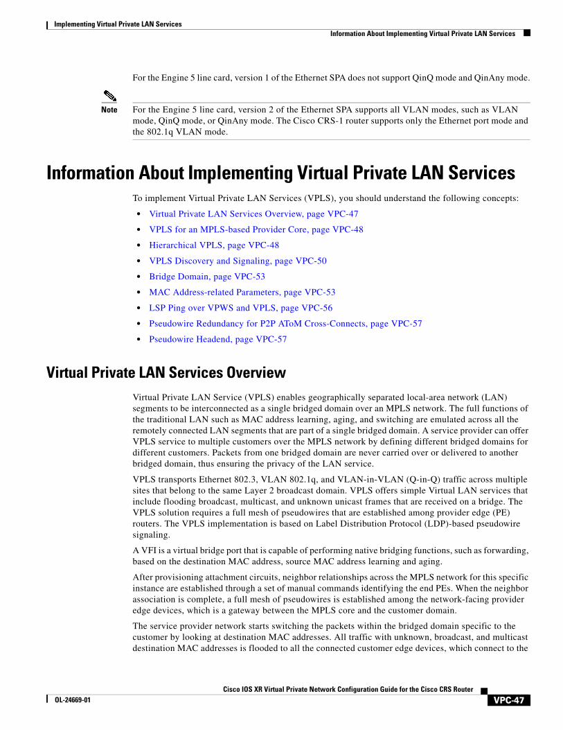
Implementing Virtual Private LAN ServicesInformation About Implementing Virtual Private LAN Services
For the Engine 5 line card, version 1 of the Ethernet SPA does not support QinQ mode and QinAny mode.
Note For the Engine 5 line card, version 2 of the Ethernet SPA supports all VLAN modes, such as VLAN mode, QinQ mode, or QinAny mode. The Cisco CRS-1 router supports only the Ethernet port mode and the 802.1q VLAN mode.
Information About Implementing Virtual Private LAN ServicesTo implement Virtual Private LAN Services (VPLS), you should understand the following concepts:
• Virtual Private LAN Services Overview, page VPC-47
• VPLS for an MPLS-based Provider Core, page VPC-48
• Hierarchical VPLS, page VPC-48
• VPLS Discovery and Signaling, page VPC-50
• Bridge Domain, page VPC-53
• MAC Address-related Parameters, page VPC-53
• LSP Ping over VPWS and VPLS, page VPC-56
• Pseudowire Redundancy for P2P AToM Cross-Connects, page VPC-57
• Pseudowire Headend, page VPC-57
Virtual Private LAN Services OverviewVirtual Private LAN Service (VPLS) enables geographically separated local-area network (LAN) segments to be interconnected as a single bridged domain over an MPLS network. The full functions of the traditional LAN such as MAC address learning, aging, and switching are emulated across all the remotely connected LAN segments that are part of a single bridged domain. A service provider can offer VPLS service to multiple customers over the MPLS network by defining different bridged domains for different customers. Packets from one bridged domain are never carried over or delivered to another bridged domain, thus ensuring the privacy of the LAN service.
VPLS transports Ethernet 802.3, VLAN 802.1q, and VLAN-in-VLAN (Q-in-Q) traffic across multiple sites that belong to the same Layer 2 broadcast domain. VPLS offers simple Virtual LAN services that include flooding broadcast, multicast, and unknown unicast frames that are received on a bridge. The VPLS solution requires a full mesh of pseudowires that are established among provider edge (PE) routers. The VPLS implementation is based on Label Distribution Protocol (LDP)-based pseudowire signaling.
A VFI is a virtual bridge port that is capable of performing native bridging functions, such as forwarding, based on the destination MAC address, source MAC address learning and aging.
After provisioning attachment circuits, neighbor relationships across the MPLS network for this specific instance are established through a set of manual commands identifying the end PEs. When the neighbor association is complete, a full mesh of pseudowires is established among the network-facing provider edge devices, which is a gateway between the MPLS core and the customer domain.
The service provider network starts switching the packets within the bridged domain specific to the customer by looking at destination MAC addresses. All traffic with unknown, broadcast, and multicast destination MAC addresses is flooded to all the connected customer edge devices, which connect to the
VPC-47Cisco IOS XR Virtual Private Network Configuration Guide for the Cisco CRS Router
OL-24669-01
Implementing Virtual Private LAN Services Information About Implementing Virtual Private LAN Services
service provider network. The network-facing provider edge devices learn the source MAC addresses as the packets are flooded. The traffic is unicasted to the customer edge device for all the learned MAC addresses.
VPLS requires the provider edge device to be MPLS-capable. The VPLS provider edge device holds all the VPLS forwarding MAC tables and Bridge Domain information. In addition, it is responsible for all flooding broadcast frames and multicast replications.
Note VPLS with Traffic Engineering Fast Reroute (TE FRR) is not supported.
VPLS for an MPLS-based Provider CoreVPLS is a multipoint Layer 2 VPN technology that connects two or more customer devices using bridging techniques. The VPLS architecture allows for the end-to-end connection between the Provider Edge (PE) routers to provide Multipoint Ethernet Services.
VPLS requires the creation of a bridge domain (Layer 2 broadcast domain) on each of the PE routers. The access connections to the bridge domain on a PE router are called attachment circuits (AC).
The attachment circuits can be a set of physical ports, virtual ports, or both that are connected to the bridge at each PE device in the network.
The MPLS/IP provider core simulates a virtual bridge that connects the multiple attachment circuits on each of the PE devices together to form a single broadcast domain. A VFI is created on the PE router for each VPLS instance. The PE routers make packet-forwarding decisions by looking up the VFI of a particular VPLS instance. The VFI acts like a virtual bridge for a given VPLS instance. More than one attachment circuit belonging to a given VPLS are connected to the VFI. The PE router establishes emulated VCs to all the other PE routers in that VPLS instance and attaches these emulated VCs to the VFI. Packet forwarding decisions are based on the data structures maintained in the VFI.
Hierarchical VPLS Hierarchical VPLS (H-VPLS) is an extension of basic VPLS that provides scaling and operational benefits. H-VPLS provides a solution to deliver Ethernet multipoint services over MPLS. H-VPLS partitions a network into several edge domains that are interconnected using an MPLS core. The use of Ethernet switches at the edge offers significant technical and economic advantages. H-VPLS also allows Ethernet point-to-point and multipoint Layer 2 VPN services, as well as Ethernet access to high-speed Internet and IP VPN services.
Two flavors of H-VPLS are:
• Ethernet access in the edge domain
• MPLS access in the edge domain
H-VPLS with Ethernet Access QinQ or QinAny
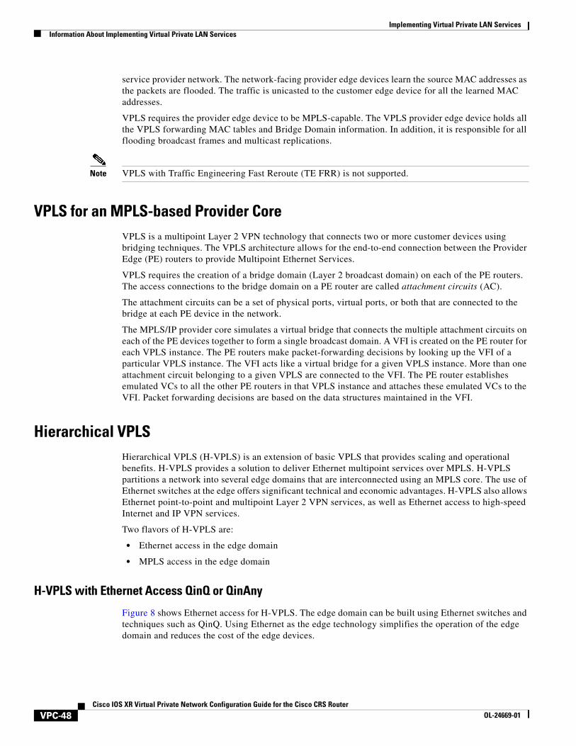
Figure 8 shows Ethernet access for H-VPLS. The edge domain can be built using Ethernet switches and techniques such as QinQ. Using Ethernet as the edge technology simplifies the operation of the edge domain and reduces the cost of the edge devices.
VPC-48Cisco IOS XR Virtual Private Network Configuration Guide for the Cisco CRS Router
OL-24669-01
Implementing Virtual Private LAN ServicesInformation About Implementing Virtual Private LAN Services
Figure 8 Ethernet Access for H-VPLS
H-VPLS with PW-access
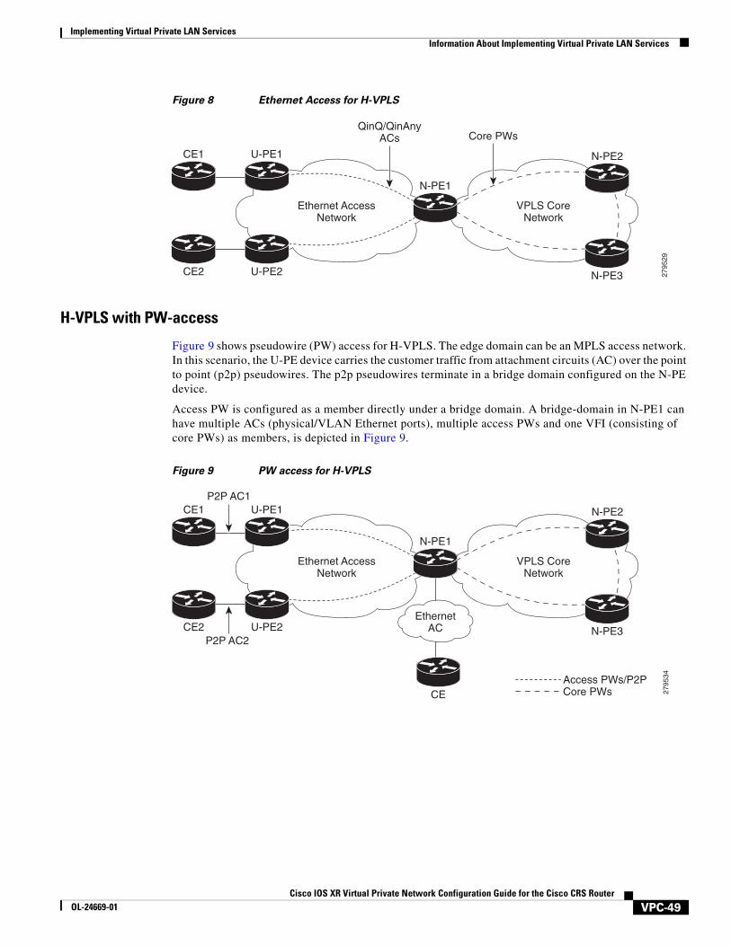
Figure 9 shows pseudowire (PW) access for H-VPLS. The edge domain can be an MPLS access network. In this scenario, the U-PE device carries the customer traffic from attachment circuits (AC) over the point to point (p2p) pseudowires. The p2p pseudowires terminate in a bridge domain configured on the N-PE device.
Access PW is configured as a member directly under a bridge domain. A bridge-domain in N-PE1 can have multiple ACs (physical/VLAN Ethernet ports), multiple access PWs and one VFI (consisting of core PWs) as members, is depicted in Figure 9.
Figure 9 PW access for H-VPLS
2795
29
CE1
CE2
U-PE1
U-PE2
Ethernet AccessNetwork
VPLS CoreNetwork
QinQ/QinAnyACs Core PWs
N-PE1
N-PE2
N-PE3
2795
34
CE1
CE2
U-PE1
U-PE2
Ethernet AccessNetwork
VPLS CoreNetwork
N-PE1
N-PE2
N-PE3
P2P AC1
P2P AC2
Access PWs/P2PCore PWs
EthernetAC
CE
VPC-49Cisco IOS XR Virtual Private Network Configuration Guide for the Cisco CRS Router
OL-24669-01
Implementing Virtual Private LAN Services Information About Implementing Virtual Private LAN Services
VPLS Discovery and SignalingVPLS is a Layer 2 multipoint service and it emulates a LAN service across a WAN. VPLS enables service providers to interconnect several LAN segments over a packet-switched network and make them behave as a single LAN. Service providers can provide a native Ethernet access connection to customers using VPLS.
The VPLS control plane consists of two important components, autodiscovery and signaling:
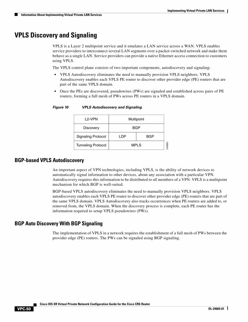
• VPLS Autodiscovery eliminates the need to manually provision VPLS neighbors. VPLS Autodiscovery enables each VPLS PE router to discover other provider edge (PE) routers that are part of the same VPLS domain.
• Once the PEs are discovered, pseudowires (PWs) are signaled and established across pairs of PE routers, forming a full mesh of PWs across PE routers in a VPLS domain.
Figure 10 VPLS Autodiscovery and Signaling
BGP-based VPLS Autodiscovery
An important aspect of VPN technologies, including VPLS, is the ability of network devices to automatically signal information to other devices, about any association with a particular VPN. Autodiscovery requires this information to be distributed to all members of a VPN. VPLS is a multipoint mechanism for which BGP is well-suited.
BGP-based VPLS autodiscovery eliminates the need to manually provision VPLS neighbors. VPLS autodiscovery enables each VPLS PE router to discover other provider edge (PE) routers that are part of the same VPLS domain. VPLS Autodiscovery also tracks occurrences when PE routers are added to, or removed from, the VPLS domain. When the discovery process is complete, each PE router has the information required to setup VPLS pseudowires (PWs).
BGP Auto Discovery With BGP Signaling
The implementation of VPLS in a network requires the establishment of a full mesh of PWs between the provider edge (PE) routers. The PWs can be signaled using BGP signaling.
2498
81
L2-VPN Multipoint
Discovery BGP
Signaling Protocol LDP BGP
Tunneling Protocol MPLS
VPC-50Cisco IOS XR Virtual Private Network Configuration Guide for the Cisco CRS Router
OL-24669-01
Implementing Virtual Private LAN ServicesInformation About Implementing Virtual Private LAN Services
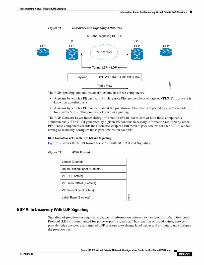
Figure 11 Discovery and Signaling Attributes
The BGP signaling and autodiscovery scheme has these components:
• A means by which a PE can learn which remote PEs are members of a given VPLS. This process is known as autodiscovery.
• A means by which a PE can learn about the pseudowire label that is expected by a given remote PE for a given VPLS. This process is known as signaling.
The BGP Network Layer Reachability Information (NLRI) takes care of both these components simultaneously. The NLRI generated by a given PE contains necessary information required by other PEs. These components enable the automatic setup of a full mesh of pseudowires for each VPLS, without having to manually configure those pseudowires on each PE.
NLRI Format for VPLS with BGP AD and Signaling
Figure 12 shows the NLRI format for VPLS with BGP AD and Signaling.
Figure 12 NLRI Format
BGP Auto Discovery With LDP Signaling
Signaling of pseudowires requires exchange of information between two endpoints. Label Distribution Protocol (LDP) is better suited for point-to-point signaling. The signaling of pseudowires, between provider edge devices, uses targeted LDP sessions to exchange label values and attributes, and configure the pseudowires.
2498
75
Payload BGP VC Label LDP IGP Label
MPLS Core
Label Signaling BGP
Tunnel LSP = LDP
Traffic Flow
CE1 PE1 PE2 CE2
2498
80
Length (2 octets)
Route Distinguisher (8 octets)
VE ID (2 octets)
VE Block Offset (2 octets)
VE Block Size (2 octets)
Label Base (3 octets)
VPC-51Cisco IOS XR Virtual Private Network Configuration Guide for the Cisco CRS Router
OL-24669-01
Implementing Virtual Private LAN Services Information About Implementing Virtual Private LAN Services
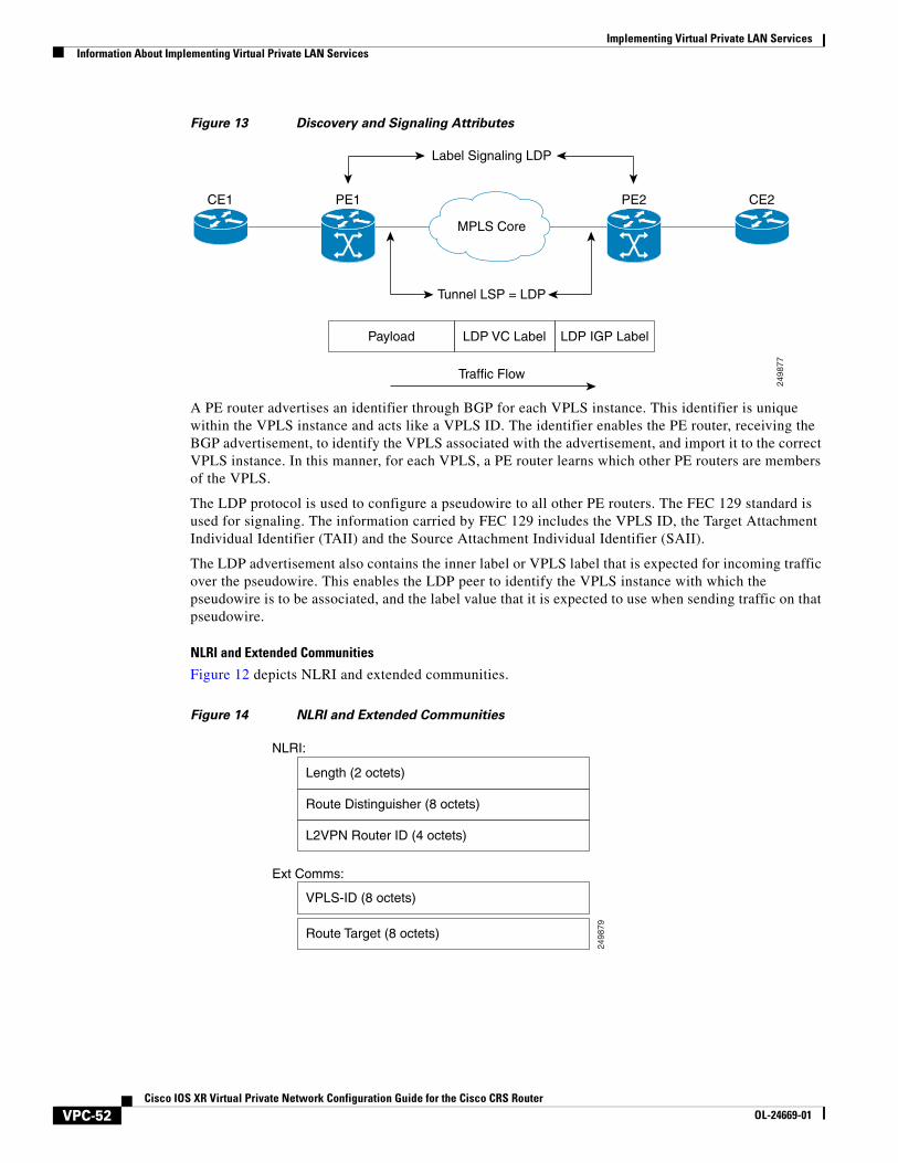
Figure 13 Discovery and Signaling Attributes
A PE router advertises an identifier through BGP for each VPLS instance. This identifier is unique within the VPLS instance and acts like a VPLS ID. The identifier enables the PE router, receiving the BGP advertisement, to identify the VPLS associated with the advertisement, and import it to the correct VPLS instance. In this manner, for each VPLS, a PE router learns which other PE routers are members of the VPLS.
The LDP protocol is used to configure a pseudowire to all other PE routers. The FEC 129 standard is used for signaling. The information carried by FEC 129 includes the VPLS ID, the Target Attachment Individual Identifier (TAII) and the Source Attachment Individual Identifier (SAII).
The LDP advertisement also contains the inner label or VPLS label that is expected for incoming traffic over the pseudowire. This enables the LDP peer to identify the VPLS instance with which the pseudowire is to be associated, and the label value that it is expected to use when sending traffic on that pseudowire.
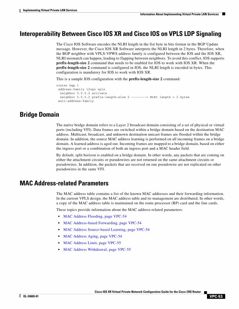
NLRI and Extended Communities
Figure 12 depicts NLRI and extended communities.
Figure 14 NLRI and Extended Communities
2498
77
Payload LDP VC Label LDP IGP Label
MPLS Core
Label Signaling LDP
Tunnel LSP = LDP
Traffic Flow
CE1 PE1 PE2 CE2
2498
79
Length (2 octets)
Route Distinguisher (8 octets)
L2VPN Router ID (4 octets)
VPLS-ID (8 octets)
Ext Comms:
NLRI:
Route Target (8 octets)
VPC-52Cisco IOS XR Virtual Private Network Configuration Guide for the Cisco CRS Router
OL-24669-01
Implementing Virtual Private LAN ServicesInformation About Implementing Virtual Private LAN Services
Interoperability Between Cisco IOS XR and Cisco IOS on VPLS LDP SignalingThe Cisco IOS Software encodes the NLRI length in the fist byte in bits format in the BGP Update message. However, the Cisco IOS XR Software interprets the NLRI length in 2 bytes. Therefore, when the BGP neighbor with VPLS-VPWS address family is configured between the IOS and the IOS XR, NLRI mismatch can happen, leading to flapping between neighbors. To avoid this conflict, IOS supports prefix-length-size 2 command that needs to be enabled for IOS to work with IOS XR. When the prefix-length-size 2 command is configured in IOS, the NLRI length is encoded in bytes. This configuration is mandatory for IOS to work with IOS XR.
This is a sample IOS configuration with the prefix-length-size 2 command:
router bgp 1 address-family l2vpn vpls neighbor 5.5.5.2 activate neighbor 5.5.5.2 prefix-length-size 2 --------> NLRI length = 2 bytes exit-address-family
Bridge DomainThe native bridge domain refers to a Layer 2 broadcast domain consisting of a set of physical or virtual ports (including VFI). Data frames are switched within a bridge domain based on the destination MAC address. Multicast, broadcast, and unknown destination unicast frames are flooded within the bridge domain. In addition, the source MAC address learning is performed on all incoming frames on a bridge domain. A learned address is aged out. Incoming frames are mapped to a bridge domain, based on either the ingress port or a combination of both an ingress port and a MAC header field.
By default, split horizon is enabled on a bridge domain. In other words, any packets that are coming on either the attachment circuits or pseudowires are not returned on the same attachment circuits or pseudowires. In addition, the packets that are received on one pseudowire are not replicated on other pseudowires in the same VFI.
MAC Address-related ParametersThe MAC address table contains a list of the known MAC addresses and their forwarding information. In the current VPLS design, the MAC address table and its management are distributed. In other words, a copy of the MAC address table is maintained on the route processor (RP) card and the line cards.
These topics provide information about the MAC address-related parameters:
• MAC Address Flooding, page VPC-54
• MAC Address-based Forwarding, page VPC-54
• MAC Address Source-based Learning, page VPC-54
• MAC Address Aging, page VPC-54
• MAC Address Limit, page VPC-55
• MAC Address Withdrawal, page VPC-55
VPC-53Cisco IOS XR Virtual Private Network Configuration Guide for the Cisco CRS Router
OL-24669-01
Implementing Virtual Private LAN Services Information About Implementing Virtual Private LAN Services
MAC Address Flooding
Ethernet services require that frames that are sent to broadcast addresses and to unknown destination addresses be flooded to all ports. To obtain flooding within VPLS broadcast models, all unknown unicast, broadcast, and multicast frames are flooded over the corresponding pseudowires and to all attachment circuits. Therefore, a PE must replicate packets across both attachment circuits and pseudowires.
MAC Address-based Forwarding
To forward a frame, a PE must associate a destination MAC address with a pseudowire or attachment circuit. This type of association is provided through a static configuration on each PE or through dynamic learning, which is flooded to all bridge ports.
Note In this case, split horizon forwarding applies; for example, frames that are coming in on an attachment circuit or pseudowire are not sent out of the same attachment circuit or pseudowire. The pseudowire frames, which are received on one pseudowire, are replicated on to other attachment circuits, VFI pseudowires and access pseudowires.
MAC Address Source-based Learning
When a frame arrives on a bridge port (for example, pseudowire or attachment circuit) and the source MAC address is unknown to the receiving PE router, the source MAC address is associated with the pseudowire or attachment circuit. Outbound frames to the MAC address are forwarded to the appropriate pseudowire or attachment circuit.
MAC address source-based learning uses the MAC address information that is learned in the hardware forwarding path. The updated MAC tables are sent to all line cards (LCs) and program the hardware for the router.
The number of learned MAC addresses is limited through configurable per-port and per-bridge domain MAC address limits.
MAC Address Aging
A MAC address in the MAC table is considered valid only for the duration of the MAC address aging time. When the time expires, the relevant MAC entries are repopulated. When the MAC aging time is configured only under a bridge domain, all the pseudowires and attachment circuits in the bridge domain use that configured MAC aging time.
A bridge forwards, floods, or drops packets based on the bridge table. The bridge table maintains both static entries and dynamic entries. Static entries are entered by the network manager or by the bridge itself. Dynamic entries are entered by the bridge learning process. A dynamic entry is automatically removed after a specified length of time, known as aging time, from the time the entry was created or last updated.
If hosts on a bridged network are likely to move, decrease the aging-time to enable the bridge to adapt to the change quickly. If hosts do not transmit continuously, increase the aging time to record the dynamic entries for a longer time, thus reducing the possibility of flooding when the hosts transmit again.
VPC-54Cisco IOS XR Virtual Private Network Configuration Guide for the Cisco CRS Router
OL-24669-01
Implementing Virtual Private LAN ServicesInformation About Implementing Virtual Private LAN Services
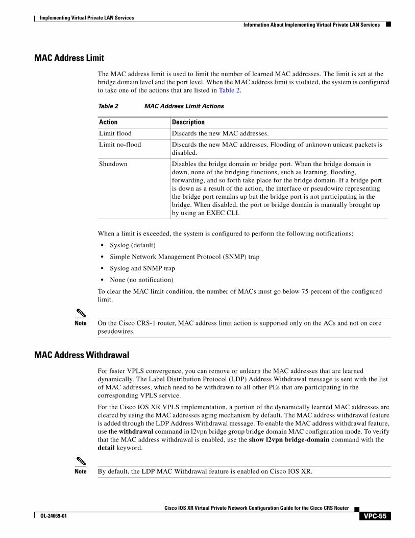
MAC Address Limit
The MAC address limit is used to limit the number of learned MAC addresses. The limit is set at the bridge domain level and the port level. When the MAC address limit is violated, the system is configured to take one of the actions that are listed in Table 2.
When a limit is exceeded, the system is configured to perform the following notifications:
• Syslog (default)
• Simple Network Management Protocol (SNMP) trap
• Syslog and SNMP trap
• None (no notification)
To clear the MAC limit condition, the number of MACs must go below 75 percent of the configured limit.
Note On the Cisco CRS-1 router, MAC address limit action is supported only on the ACs and not on core pseudowires.
MAC Address Withdrawal
For faster VPLS convergence, you can remove or unlearn the MAC addresses that are learned dynamically. The Label Distribution Protocol (LDP) Address Withdrawal message is sent with the list of MAC addresses, which need to be withdrawn to all other PEs that are participating in the corresponding VPLS service.
For the Cisco IOS XR VPLS implementation, a portion of the dynamically learned MAC addresses are cleared by using the MAC addresses aging mechanism by default. The MAC address withdrawal feature is added through the LDP Address Withdrawal message. To enable the MAC address withdrawal feature, use the withdrawal command in l2vpn bridge group bridge domain MAC configuration mode. To verify that the MAC address withdrawal is enabled, use the show l2vpn bridge-domain command with the detail keyword.
Note By default, the LDP MAC Withdrawal feature is enabled on Cisco IOS XR.
Table 2 MAC Address Limit Actions
Action Description
Limit flood Discards the new MAC addresses.
Limit no-flood Discards the new MAC addresses. Flooding of unknown unicast packets is disabled.
Shutdown Disables the bridge domain or bridge port. When the bridge domain is down, none of the bridging functions, such as learning, flooding, forwarding, and so forth take place for the bridge domain. If a bridge port is down as a result of the action, the interface or pseudowire representing the bridge port remains up but the bridge port is not participating in the bridge. When disabled, the port or bridge domain is manually brought up by using an EXEC CLI.
VPC-55Cisco IOS XR Virtual Private Network Configuration Guide for the Cisco CRS Router
OL-24669-01
Implementing Virtual Private LAN Services Information About Implementing Virtual Private LAN Services
The LDP MAC Withdrawal feature is generated due to the following events:
• Attachment circuit goes down. You can remove or add the attachment circuit through the CLI.
• MAC withdrawal messages are received over a VFI pseudowire and are not propagated over access pseudowires. RFC 4762 specifies that both wildcards (by means of an empty Type, Length and Value [TLV]) and a specific MAC address withdrawal. Cisco IOS XR software supports only a wildcard MAC address withdrawal.
LSP Ping over VPWS and VPLSFor Cisco IOS XR software, the existing support for the Label Switched Path (LSP) ping and traceroute verification mechanisms for point-to-point pseudowires (signaled using LDP FEC128) is extended to cover the pseudowires that are associated with the VFI (VPLS). Currently, the support for the LSP ping and traceroute is limited to manually configured VPLS and access pseudowires (signaled using LDP FEC128). Virtual Circuit Connection Verification (VCCV) is also supported on access pseudowires. For information about VCCV support and the ping mpls pseudowire command, see Cisco IOS XR MPLS Command Reference for the Cisco CRS Router.
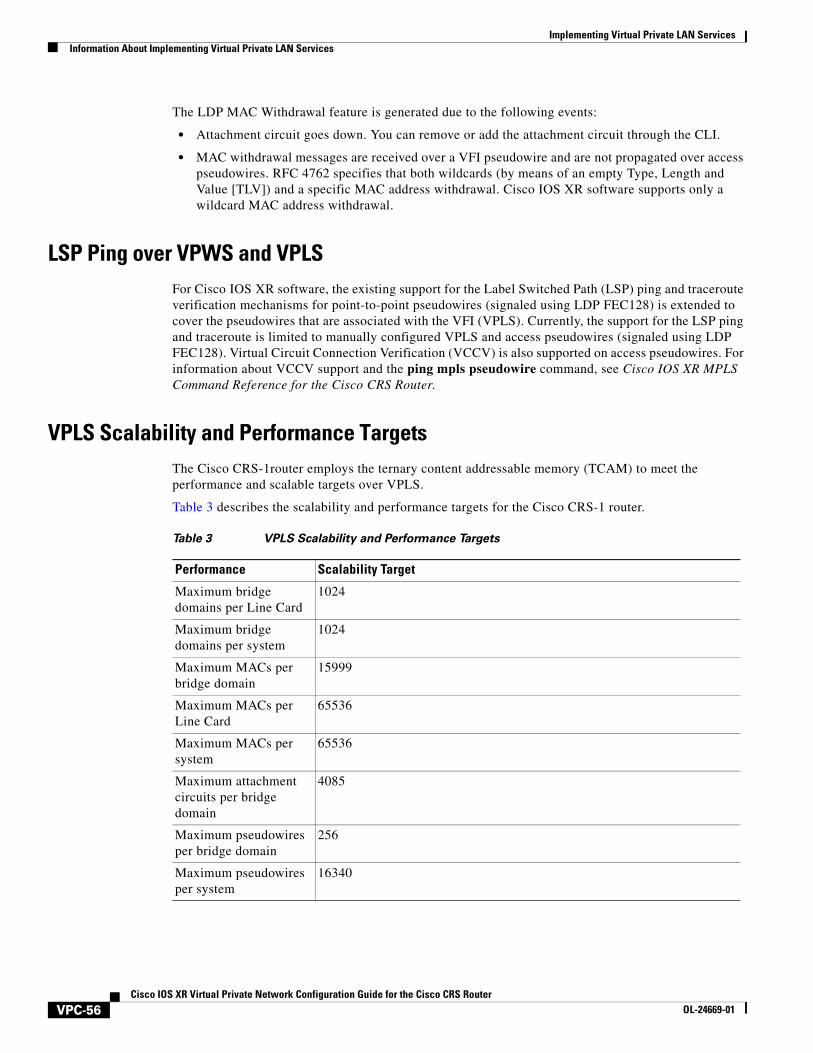
VPLS Scalability and Performance TargetsThe Cisco CRS-1router employs the ternary content addressable memory (TCAM) to meet the performance and scalable targets over VPLS.
Table 3 describes the scalability and performance targets for the Cisco CRS-1 router.
Table 3 VPLS Scalability and Performance Targets
Performance Scalability Target
Maximum bridge domains per Line Card
1024
Maximum bridge domains per system
1024
Maximum MACs per bridge domain
15999
Maximum MACs per Line Card
65536
Maximum MACs per system
65536
Maximum attachment circuits per bridge domain
4085
Maximum pseudowires per bridge domain
256
Maximum pseudowires per system
16340
VPC-56Cisco IOS XR Virtual Private Network Configuration Guide for the Cisco CRS Router
OL-24669-01
Implementing Virtual Private LAN ServicesInformation About Implementing Virtual Private LAN Services
Pseudowire Redundancy for P2P AToM Cross-ConnectsBackup pseudowires (PW) are associated with the corresponding primary pseudowires. A backup PW is not programmed to forward data when inactive. It is activated only if a primary PW fails. This is known as pseudowire redundancy. The primary reason for backing up a PW is to reduce traffic loss when a primary PW fails. When the primary PW is active again, it resumes its activity.
A primary PW can be associated with only one backup PW. Similarly, a backup PW can be associated with only one primary PW.
It is recommended to enable pseudowire status time length value (TLV) for optimal switchover performance.
Note This feature is supported only for an AToM instance on the Cisco XR 12000 Series Router, and for an EoMPLS instance on the Cisco CRS-1 router.
Pseudowire HeadendPseudowires (PWs) enable payloads to be transparently carried across IP/MPLS packet-switched networks (PSNs). Service providers are now extending PW connectivity into the access and aggregation regions of their networks. PWs are regarded as simple and manageable lightweight tunnels for returning customer traffic into core networks.
The PW headend (PWHE) feature provides a Layer 3 (L3) virtual interface representation of a PW on an service provider edge (PE), that allows the backhaul of customer packets over PWs and the application of L3 features, such as QoS (for example: policing and shaping), and access lists (ACLs) on customer packets on the PW.
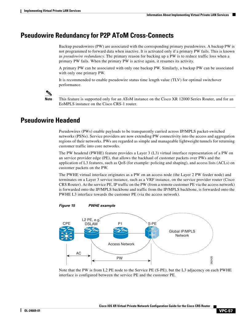
The PWHE virtual interface originates as a PW on an access node (the Layer 2 PW feeder node) and terminates on a Layer 3 service instance, such as a VRF instance, on the service provider router (Cisco CRS Router). At the service PE, IP traffic on the PW (from a remote customer PE via the access network) is forwarded onto the IP/MPLS backbone and traffic from the IP/MPLS backbone, is forwarded onto the PWHE L3 interface towards the customer PE (via the access network).
Figure 15 PWHE example
Note that the PW is from L2 PE node to the Service PE (S-PE), but the L3 adjacency on each PWHE interface is configured between the service PE and the customer PE.
Access Network
2824
20
L2 PE, e.g.DSLAM P1CPE
ACPW
S-PE
Global IP/MPLSNetwork
VPC-57Cisco IOS XR Virtual Private Network Configuration Guide for the Cisco CRS Router
OL-24669-01
Implementing Virtual Private LAN Services How to Implement Virtual Private LAN Services
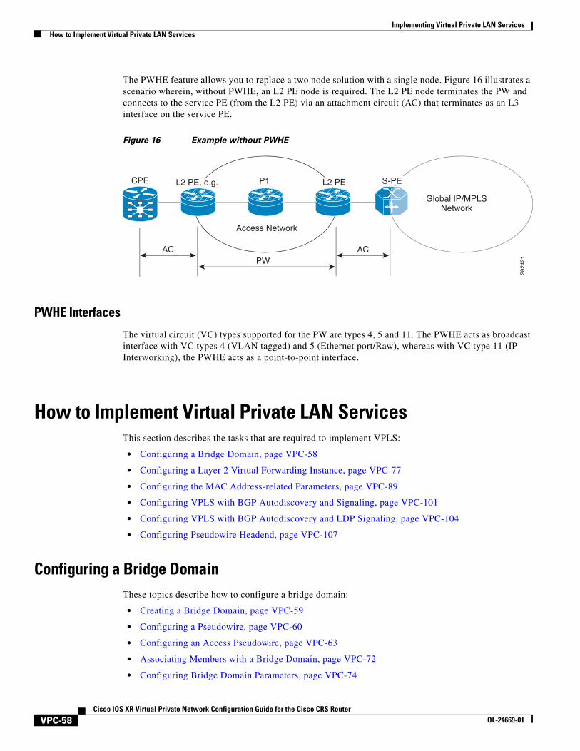
The PWHE feature allows you to replace a two node solution with a single node. Figure 16 illustrates a scenario wherein, without PWHE, an L2 PE node is required. The L2 PE node terminates the PW and connects to the service PE (from the L2 PE) via an attachment circuit (AC) that terminates as an L3 interface on the service PE.
Figure 16 Example without PWHE
PWHE Interfaces
The virtual circuit (VC) types supported for the PW are types 4, 5 and 11. The PWHE acts as broadcast interface with VC types 4 (VLAN tagged) and 5 (Ethernet port/Raw), whereas with VC type 11 (IP Interworking), the PWHE acts as a point-to-point interface.
How to Implement Virtual Private LAN ServicesThis section describes the tasks that are required to implement VPLS:
• Configuring a Bridge Domain, page VPC-58
• Configuring a Layer 2 Virtual Forwarding Instance, page VPC-77
• Configuring the MAC Address-related Parameters, page VPC-89
• Configuring VPLS with BGP Autodiscovery and Signaling, page VPC-101
• Configuring VPLS with BGP Autodiscovery and LDP Signaling, page VPC-104
• Configuring Pseudowire Headend, page VPC-107
Configuring a Bridge DomainThese topics describe how to configure a bridge domain:
• Creating a Bridge Domain, page VPC-59
• Configuring a Pseudowire, page VPC-60
• Configuring an Access Pseudowire, page VPC-63
• Associating Members with a Bridge Domain, page VPC-72
• Configuring Bridge Domain Parameters, page VPC-74
Access Network
2824
21
L2 PE, e.g. P1 L2 PECPE
AC ACPW
S-PE
Global IP/MPLSNetwork
VPC-58Cisco IOS XR Virtual Private Network Configuration Guide for the Cisco CRS Router
OL-24669-01
Implementing Virtual Private LAN ServicesHow to Implement Virtual Private LAN Services
• Disabling a Bridge Domain, page VPC-75
• Configuring a Layer 2 Virtual Forwarding Instance, page VPC-77
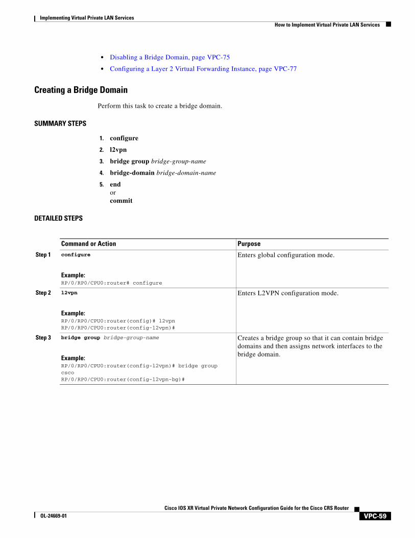
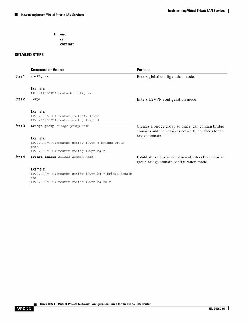
Creating a Bridge Domain
Perform this task to create a bridge domain.
SUMMARY STEPS
1. configure
2. l2vpn
3. bridge group bridge-group-name
4. bridge-domain bridge-domain-name
5. endorcommit
DETAILED STEPS
Command or Action Purpose
Step 1 configure
Example:RP/0/RP0/CPU0:router# configure
Enters global configuration mode.
Step 2 l2vpn
Example:RP/0/RP0/CPU0:router(config)# l2vpnRP/0/RP0/CPU0:router(config-l2vpn)#
Enters L2VPN configuration mode.
Step 3 bridge group bridge-group-name
Example:RP/0/RP0/CPU0:router(config-l2vpn)# bridge group cscoRP/0/RP0/CPU0:router(config-l2vpn-bg)#
Creates a bridge group so that it can contain bridge domains and then assigns network interfaces to the bridge domain.
VPC-59Cisco IOS XR Virtual Private Network Configuration Guide for the Cisco CRS Router
OL-24669-01
Implementing Virtual Private LAN Services How to Implement Virtual Private LAN Services
Configuring a Pseudowire
Perform this task to configure a pseudowire under a bridge domain.
SUMMARY STEPS
1. configure
2. l2vpn
3. bridge group bridge group name
4. bridge-domain bridge-domain name
5. vfi {vfi name}
6. exit
7. neighbor {A.B.C.D} {pw-id value}
8. endorcommit
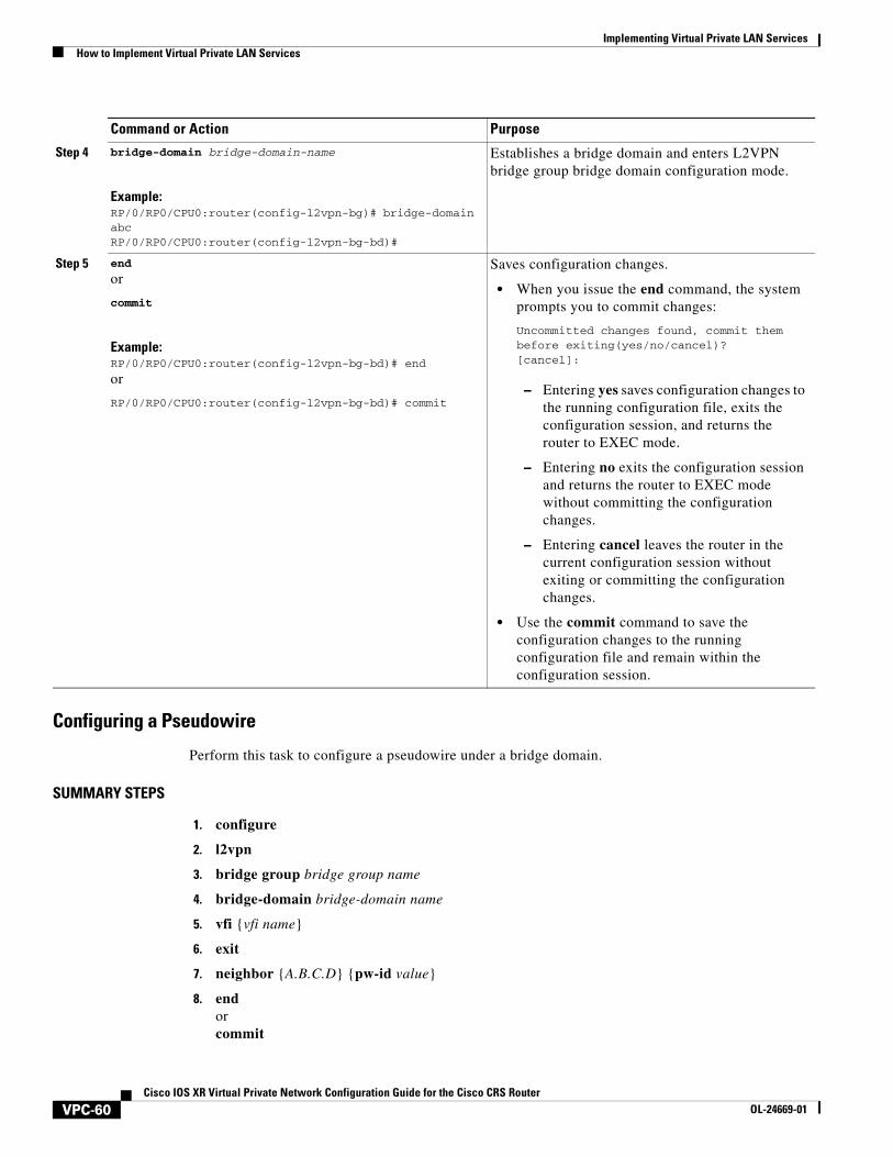
Step 4 bridge-domain bridge-domain-name
Example:RP/0/RP0/CPU0:router(config-l2vpn-bg)# bridge-domain abcRP/0/RP0/CPU0:router(config-l2vpn-bg-bd)#
Establishes a bridge domain and enters L2VPN bridge group bridge domain configuration mode.
Step 5 end
or
commit
Example:RP/0/RP0/CPU0:router(config-l2vpn-bg-bd)# end
or
RP/0/RP0/CPU0:router(config-l2vpn-bg-bd)# commit
Saves configuration changes.
• When you issue the end command, the system prompts you to commit changes:
Uncommitted changes found, commit them before exiting(yes/no/cancel)?[cancel]:
– Entering yes saves configuration changes to the running configuration file, exits the configuration session, and returns the router to EXEC mode.
– Entering no exits the configuration session and returns the router to EXEC mode without committing the configuration changes.
– Entering cancel leaves the router in the current configuration session without exiting or committing the configuration changes.
• Use the commit command to save the configuration changes to the running configuration file and remain within the configuration session.
Command or Action Purpose
VPC-60Cisco IOS XR Virtual Private Network Configuration Guide for the Cisco CRS Router
OL-24669-01
Implementing Virtual Private LAN ServicesHow to Implement Virtual Private LAN Services
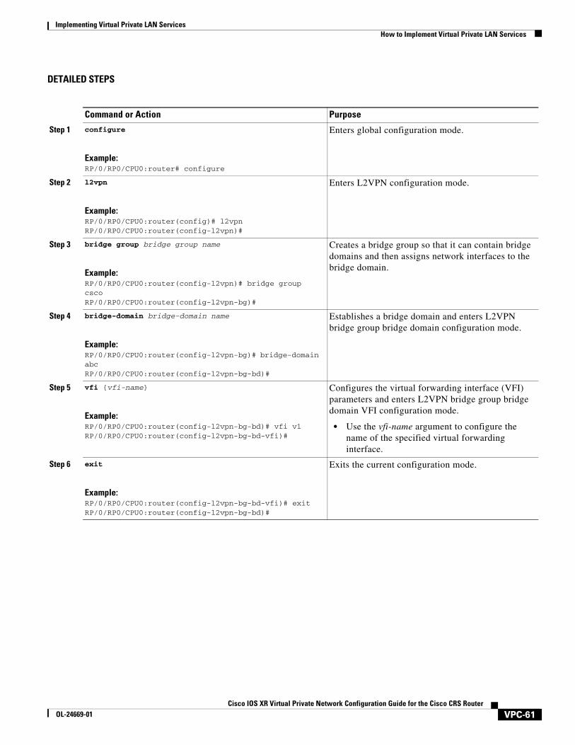
DETAILED STEPS
Command or Action Purpose
Step 1 configure
Example:RP/0/RP0/CPU0:router# configure
Enters global configuration mode.
Step 2 l2vpn
Example:RP/0/RP0/CPU0:router(config)# l2vpnRP/0/RP0/CPU0:router(config-l2vpn)#
Enters L2VPN configuration mode.
Step 3 bridge group bridge group name
Example:RP/0/RP0/CPU0:router(config-l2vpn)# bridge group cscoRP/0/RP0/CPU0:router(config-l2vpn-bg)#
Creates a bridge group so that it can contain bridge domains and then assigns network interfaces to the bridge domain.
Step 4 bridge-domain bridge-domain name
Example:RP/0/RP0/CPU0:router(config-l2vpn-bg)# bridge-domain abcRP/0/RP0/CPU0:router(config-l2vpn-bg-bd)#
Establishes a bridge domain and enters L2VPN bridge group bridge domain configuration mode.
Step 5 vfi {vfi-name}
Example:RP/0/RP0/CPU0:router(config-l2vpn-bg-bd)# vfi v1RP/0/RP0/CPU0:router(config-l2vpn-bg-bd-vfi)#
Configures the virtual forwarding interface (VFI) parameters and enters L2VPN bridge group bridge domain VFI configuration mode.
• Use the vfi-name argument to configure the name of the specified virtual forwarding interface.
Step 6 exit
Example:RP/0/RP0/CPU0:router(config-l2vpn-bg-bd-vfi)# exitRP/0/RP0/CPU0:router(config-l2vpn-bg-bd)#
Exits the current configuration mode.
VPC-61Cisco IOS XR Virtual Private Network Configuration Guide for the Cisco CRS Router
OL-24669-01
Implementing Virtual Private LAN Services How to Implement Virtual Private LAN Services
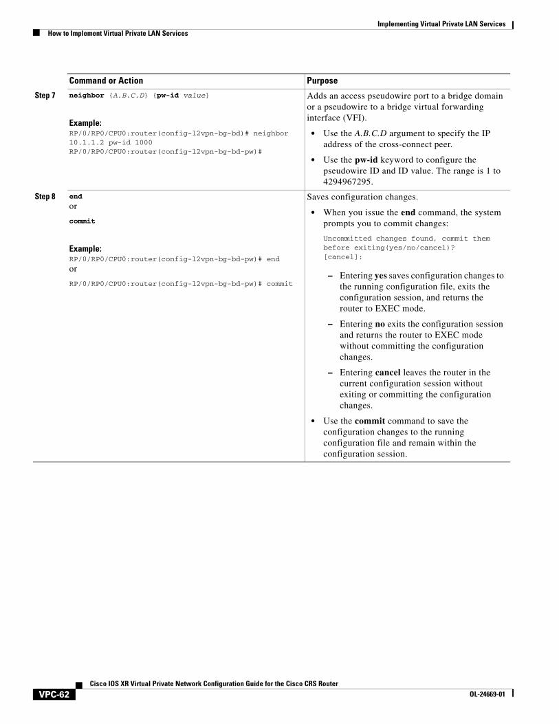
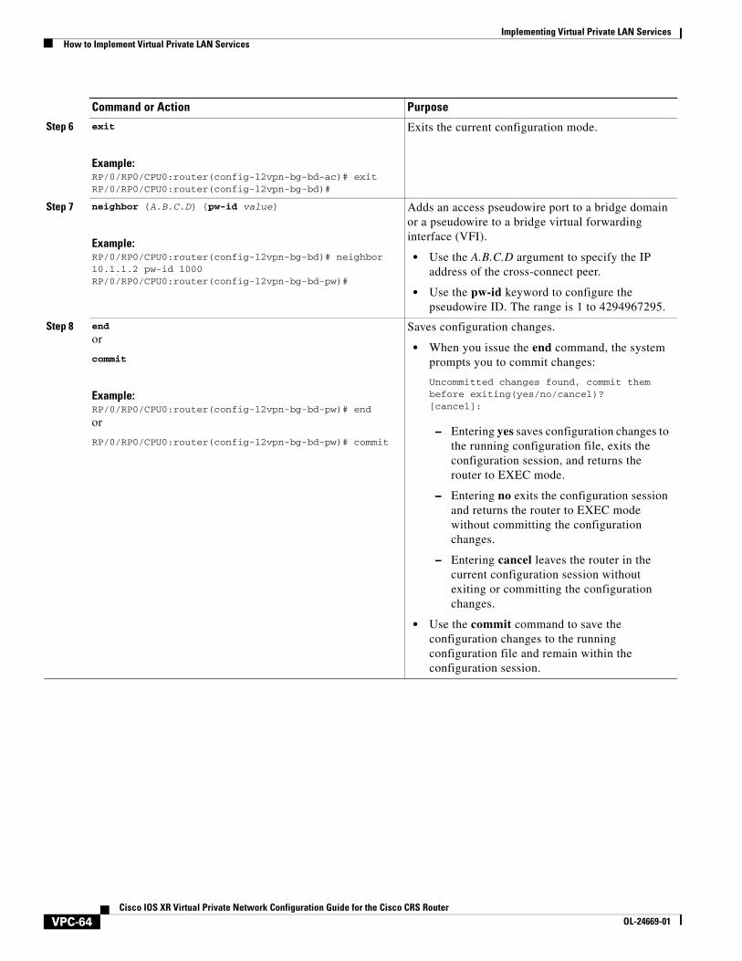
Step 7 neighbor {A.B.C.D} {pw-id value}
Example:RP/0/RP0/CPU0:router(config-l2vpn-bg-bd)# neighbor 10.1.1.2 pw-id 1000RP/0/RP0/CPU0:router(config-l2vpn-bg-bd-pw)#
Adds an access pseudowire port to a bridge domain or a pseudowire to a bridge virtual forwarding interface (VFI).
• Use the A.B.C.D argument to specify the IP address of the cross-connect peer.
• Use the pw-id keyword to configure the pseudowire ID and ID value. The range is 1 to 4294967295.
Step 8 end
or
commit
Example:RP/0/RP0/CPU0:router(config-l2vpn-bg-bd-pw)# end
or
RP/0/RP0/CPU0:router(config-l2vpn-bg-bd-pw)# commit
Saves configuration changes.
• When you issue the end command, the system prompts you to commit changes:
Uncommitted changes found, commit them before exiting(yes/no/cancel)?[cancel]:
– Entering yes saves configuration changes to the running configuration file, exits the configuration session, and returns the router to EXEC mode.
– Entering no exits the configuration session and returns the router to EXEC mode without committing the configuration changes.
– Entering cancel leaves the router in the current configuration session without exiting or committing the configuration changes.
• Use the commit command to save the configuration changes to the running configuration file and remain within the configuration session.
Command or Action Purpose
VPC-62Cisco IOS XR Virtual Private Network Configuration Guide for the Cisco CRS Router
OL-24669-01
Implementing Virtual Private LAN ServicesHow to Implement Virtual Private LAN Services
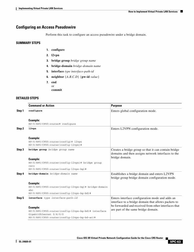
Configuring an Access Pseudowire
Perform this task to configure an access pseudowire under a bridge domain.
SUMMARY STEPS
1. configure
2. l2vpn
3. bridge group bridge group name
4. bridge-domain bridge-domain name
5. interface type interface-path-id
6. neighbor {A.B.C.D} {pw-id value}
7. endorcommit
DETAILED STEPS
Command or Action Purpose
Step 1 configure
Example:RP/0/RP0/CPU0:router# configure
Enters global configuration mode.
Step 2 l2vpn
Example:RP/0/RP0/CPU0:router(config)# l2vpnRP/0/RP0/CPU0:router(config-l2vpn)#
Enters L2VPN configuration mode.
Step 3 bridge group bridge group name
Example:RP/0/RP0/CPU0:router(config-l2vpn)# bridge group cscoRP/0/RP0/CPU0:router(config-l2vpn-bg)#
Creates a bridge group so that it can contain bridge domains and then assigns network interfaces to the bridge domain.
Step 4 bridge-domain bridge-domain name
Example:RP/0/RP0/CPU0:router(config-l2vpn-bg)# bridge-domain abcRP/0/RP0/CPU0:router(config-l2vpn-bg-bd)#
Establishes a bridge domain and enters L2VPN bridge group bridge domain configuration mode.
Step 5 interface type interface-path-id
Example:RP/0/RP0/CPU0:router(config-l2vpn-bg-bd)# interface GigabitEthernet 0/4/0/0RP/0/RP0/CPU0:router(config-l2vpn-bg-bd-ac)#
Enters interface configuration mode and adds an interface to a bridge domain that allows packets to be forwarded and received from other interfaces that are part of the same bridge domain.
VPC-63Cisco IOS XR Virtual Private Network Configuration Guide for the Cisco CRS Router
OL-24669-01
Implementing Virtual Private LAN Services How to Implement Virtual Private LAN Services
Step 6 exit
Example:RP/0/RP0/CPU0:router(config-l2vpn-bg-bd-ac)# exitRP/0/RP0/CPU0:router(config-l2vpn-bg-bd)#
Exits the current configuration mode.
Step 7 neighbor {A.B.C.D} {pw-id value}
Example:RP/0/RP0/CPU0:router(config-l2vpn-bg-bd)# neighbor 10.1.1.2 pw-id 1000RP/0/RP0/CPU0:router(config-l2vpn-bg-bd-pw)#
Adds an access pseudowire port to a bridge domain or a pseudowire to a bridge virtual forwarding interface (VFI).
• Use the A.B.C.D argument to specify the IP address of the cross-connect peer.
• Use the pw-id keyword to configure the pseudowire ID. The range is 1 to 4294967295.
Step 8 end
or
commit
Example:RP/0/RP0/CPU0:router(config-l2vpn-bg-bd-pw)# end
or
RP/0/RP0/CPU0:router(config-l2vpn-bg-bd-pw)# commit
Saves configuration changes.
• When you issue the end command, the system prompts you to commit changes:
Uncommitted changes found, commit them before exiting(yes/no/cancel)?[cancel]:
– Entering yes saves configuration changes to the running configuration file, exits the configuration session, and returns the router to EXEC mode.
– Entering no exits the configuration session and returns the router to EXEC mode without committing the configuration changes.
– Entering cancel leaves the router in the current configuration session without exiting or committing the configuration changes.
• Use the commit command to save the configuration changes to the running configuration file and remain within the configuration session.
Command or Action Purpose
VPC-64Cisco IOS XR Virtual Private Network Configuration Guide for the Cisco CRS Router
OL-24669-01
Implementing Virtual Private LAN ServicesHow to Implement Virtual Private LAN Services
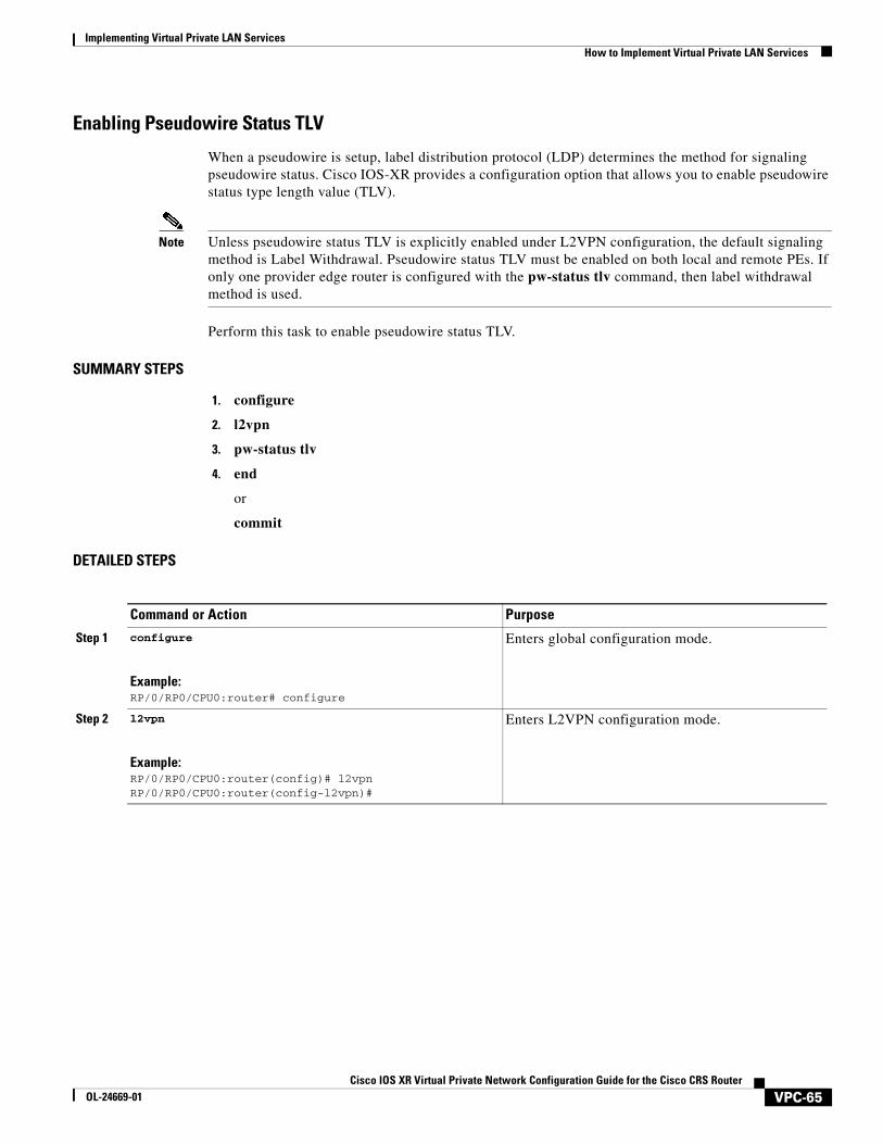
Enabling Pseudowire Status TLV
When a pseudowire is setup, label distribution protocol (LDP) determines the method for signaling pseudowire status. Cisco IOS-XR provides a configuration option that allows you to enable pseudowire status type length value (TLV).
Note Unless pseudowire status TLV is explicitly enabled under L2VPN configuration, the default signaling method is Label Withdrawal. Pseudowire status TLV must be enabled on both local and remote PEs. If only one provider edge router is configured with the pw-status tlv command, then label withdrawal method is used.
Perform this task to enable pseudowire status TLV.
SUMMARY STEPS
1. configure
2. l2vpn
3. pw-status tlv
4. end
or
commit
DETAILED STEPS
Command or Action Purpose
Step 1 configure
Example:RP/0/RP0/CPU0:router# configure
Enters global configuration mode.
Step 2 l2vpn
Example:RP/0/RP0/CPU0:router(config)# l2vpnRP/0/RP0/CPU0:router(config-l2vpn)#
Enters L2VPN configuration mode.
VPC-65Cisco IOS XR Virtual Private Network Configuration Guide for the Cisco CRS Router
OL-24669-01
Implementing Virtual Private LAN Services How to Implement Virtual Private LAN Services
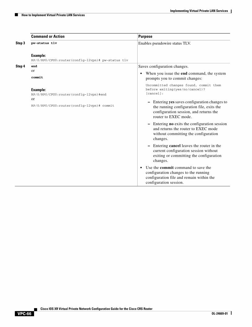
Step 3 pw-status tlv
Example:RP/0/RP0/CPU0:router(config-l2vpn)# pw-status tlv
Enables pseudowire status TLV.
Step 4 end
or
commit
Example:RP/0/RP0/CPU0:router(config-l2vpn)#end
or
RP/0/RP0/CPU0:router(config-l2vpn)# commit
Saves configuration changes.
• When you issue the end command, the system prompts you to commit changes:
Uncommitted changes found, commit them before exiting(yes/no/cancel)?[cancel]:
– Entering yes saves configuration changes to the running configuration file, exits the configuration session, and returns the router to EXEC mode.
– Entering no exits the configuration session and returns the router to EXEC mode without committing the configuration changes.
– Entering cancel leaves the router in the current configuration session without exiting or committing the configuration changes.
• Use the commit command to save the configuration changes to the running configuration file and remain within the configuration session.
Command or Action Purpose
VPC-66Cisco IOS XR Virtual Private Network Configuration Guide for the Cisco CRS Router
OL-24669-01
Implementing Virtual Private LAN ServicesHow to Implement Virtual Private LAN Services
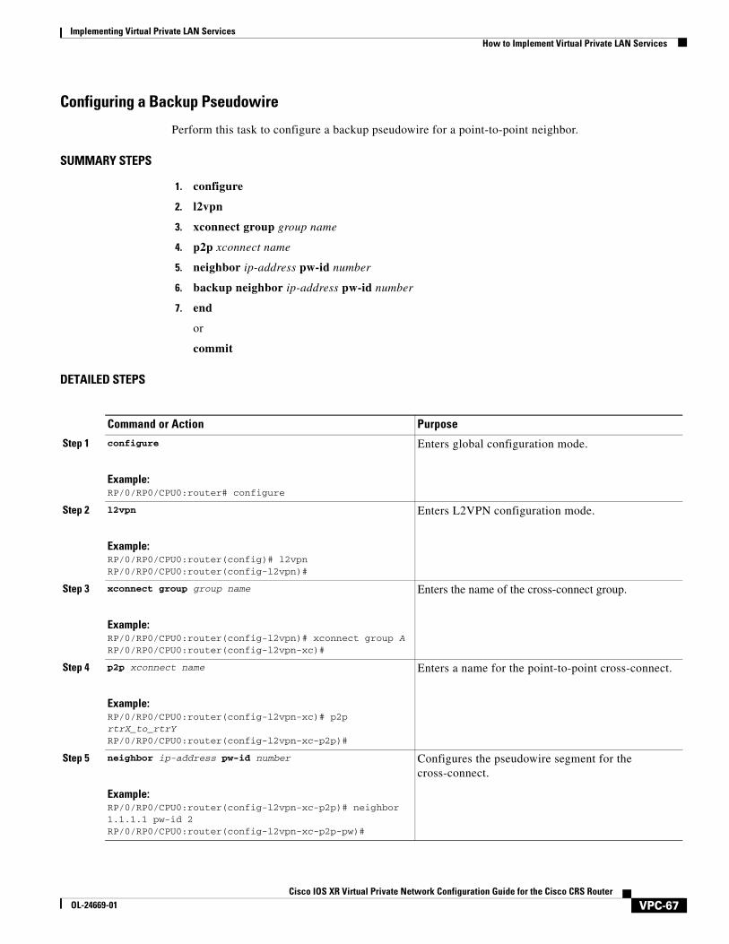
Configuring a Backup Pseudowire
Perform this task to configure a backup pseudowire for a point-to-point neighbor.
SUMMARY STEPS
1. configure
2. l2vpn
3. xconnect group group name
4. p2p xconnect name
5. neighbor ip-address pw-id number
6. backup neighbor ip-address pw-id number
7. end
or
commit
DETAILED STEPS
Command or Action Purpose
Step 1 configure
Example:RP/0/RP0/CPU0:router# configure
Enters global configuration mode.
Step 2 l2vpn
Example:RP/0/RP0/CPU0:router(config)# l2vpnRP/0/RP0/CPU0:router(config-l2vpn)#
Enters L2VPN configuration mode.
Step 3 xconnect group group name
Example:RP/0/RP0/CPU0:router(config-l2vpn)# xconnect group ARP/0/RP0/CPU0:router(config-l2vpn-xc)#
Enters the name of the cross-connect group.
Step 4 p2p xconnect name
Example:RP/0/RP0/CPU0:router(config-l2vpn-xc)# p2p rtrX_to_rtrYRP/0/RP0/CPU0:router(config-l2vpn-xc-p2p)#
Enters a name for the point-to-point cross-connect.
Step 5 neighbor ip-address pw-id number
Example:RP/0/RP0/CPU0:router(config-l2vpn-xc-p2p)# neighbor 1.1.1.1 pw-id 2RP/0/RP0/CPU0:router(config-l2vpn-xc-p2p-pw)#
Configures the pseudowire segment for the cross-connect.
VPC-67Cisco IOS XR Virtual Private Network Configuration Guide for the Cisco CRS Router
OL-24669-01
Implementing Virtual Private LAN Services How to Implement Virtual Private LAN Services
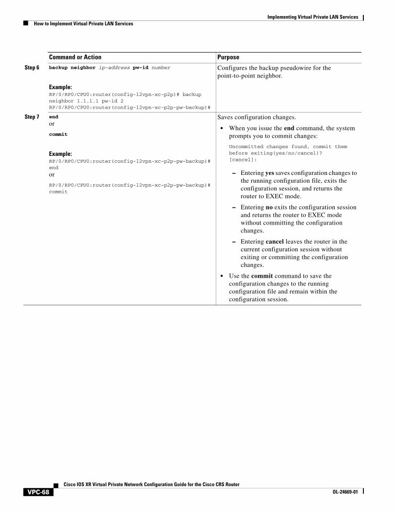
Step 6 backup neighbor ip-address pw-id number
Example:RP/0/RP0/CPU0:router(config-l2vpn-xc-p2p)# backup neighbor 1.1.1.1 pw-id 2RP/0/RP0/CPU0:router(config-l2vpn-xc-p2p-pw-backup)#
Configures the backup pseudowire for the point-to-point neighbor.
Step 7 end
or
commit
Example:RP/0/RP0/CPU0:router(config-l2vpn-xc-p2p-pw-backup)#end
or
RP/0/RP0/CPU0:router(config-l2vpn-xc-p2p-pw-backup)# commit
Saves configuration changes.
• When you issue the end command, the system prompts you to commit changes:
Uncommitted changes found, commit them before exiting(yes/no/cancel)?[cancel]:
– Entering yes saves configuration changes to the running configuration file, exits the configuration session, and returns the router to EXEC mode.
– Entering no exits the configuration session and returns the router to EXEC mode without committing the configuration changes.
– Entering cancel leaves the router in the current configuration session without exiting or committing the configuration changes.
• Use the commit command to save the configuration changes to the running configuration file and remain within the configuration session.
Command or Action Purpose
VPC-68Cisco IOS XR Virtual Private Network Configuration Guide for the Cisco CRS Router
OL-24669-01
Implementing Virtual Private LAN ServicesHow to Implement Virtual Private LAN Services
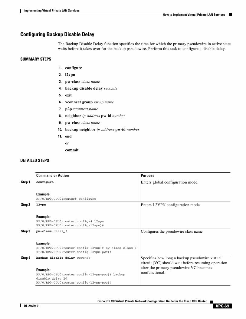
Configuring Backup Disable Delay
The Backup Disable Delay function specifies the time for which the primary pseudowire in active state waits before it takes over for the backup pseudowire. Perform this task to configure a disable delay.
SUMMARY STEPS
1. configure
2. l2vpn
3. pw-class class name
4. backup disable delay seconds
5. exit
6. xconnect group group name
7. p2p xconnect name
8. neighbor ip-address pw-id number
9. pw-class class name
10. backup neighbor ip-address pw-id number
11. end
or
commit
DETAILED STEPS
Command or Action Purpose
Step 1 configure
Example:RP/0/RP0/CPU0:router# configure
Enters global configuration mode.
Step 2 l2vpn
Example:RP/0/RP0/CPU0:router(config)# l2vpnRP/0/RP0/CPU0:router(config-l2vpn)#
Enters L2VPN configuration mode.
Step 3 pw-class class_1
Example:RP/0/RP0/CPU0:router(config-l2vpn)# pw-class class_1RP/0/RP0/CPU0:router(config-l2vpn-pwc)#
Configures the pseudowire class name.
Step 4 backup disable delay seconds
Example:RP/0/RP0/CPU0:router(config-l2vpn-pwc)# backup disable delay 20RP/0/RP0/CPU0:router(config-l2vpn-pwc)#
Specifies how long a backup pseudowire virtual circuit (VC) should wait before resuming operation after the primary pseudowire VC becomes nonfunctional.
VPC-69Cisco IOS XR Virtual Private Network Configuration Guide for the Cisco CRS Router
OL-24669-01
Implementing Virtual Private LAN Services How to Implement Virtual Private LAN Services
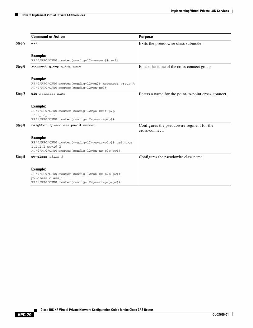
Step 5 exit
Example:RP/0/RP0/CPU0:router(config-l2vpn-pwc)# exit
Exits the pseudowire class submode.
Step 6 xconnect group group name
Example:RP/0/RP0/CPU0:router(config-l2vpn)# xconnect group ARP/0/RP0/CPU0:router(config-l2vpn-xc)#
Enters the name of the cross-connect group.
Step 7 p2p xconnect name
Example:RP/0/RP0/CPU0:router(config-l2vpn-xc)# p2p rtrX_to_rtrYRP/0/RP0/CPU0:router(config-l2vpn-xc-p2p)#
Enters a name for the point-to-point cross-connect.
Step 8 neighbor ip-address pw-id number
Example:RP/0/RP0/CPU0:router(config-l2vpn-xc-p2p)# neighbor 1.1.1.1 pw-id 2RP/0/RP0/CPU0:router(config-l2vpn-xc-p2p-pw)#
Configures the pseudowire segment for the cross-connect.
Step 9 pw-class class_1
Example:RP/0/RP0/CPU0:router(config-l2vpn-xc-p2p-pw)# pw-class class_1RP/0/RP0/CPU0:router(config-l2vpn-xc-p2p-pw)#
Configures the pseudowire class name.
Command or Action Purpose
VPC-70Cisco IOS XR Virtual Private Network Configuration Guide for the Cisco CRS Router
OL-24669-01
Implementing Virtual Private LAN ServicesHow to Implement Virtual Private LAN Services
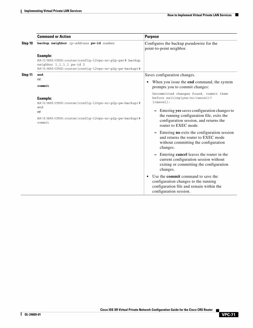
Step 10 backup neighbor ip-address pw-id number
Example:RP/0/RP0/CPU0:router(config-l2vpn-xc-p2p-pw)# backup neighbor 1.1.1.1 pw-id 2RP/0/RP0/CPU0:router(config-l2vpn-xc-p2p-pw-backup)#
Configures the backup pseudowire for the point-to-point neighbor.
Step 11 end
or
commit
Example:RP/0/RP0/CPU0:router(config-l2vpn-xc-p2p-pw-backup)#end
or
RP/0/RP0/CPU0:router(config-l2vpn-xc-p2p-pw-backup)# commit
Saves configuration changes.
• When you issue the end command, the system prompts you to commit changes:
Uncommitted changes found, commit them before exiting(yes/no/cancel)?[cancel]:
– Entering yes saves configuration changes to the running configuration file, exits the configuration session, and returns the router to EXEC mode.
– Entering no exits the configuration session and returns the router to EXEC mode without committing the configuration changes.
– Entering cancel leaves the router in the current configuration session without exiting or committing the configuration changes.
• Use the commit command to save the configuration changes to the running configuration file and remain within the configuration session.
Command or Action Purpose
VPC-71Cisco IOS XR Virtual Private Network Configuration Guide for the Cisco CRS Router
OL-24669-01
Implementing Virtual Private LAN Services How to Implement Virtual Private LAN Services
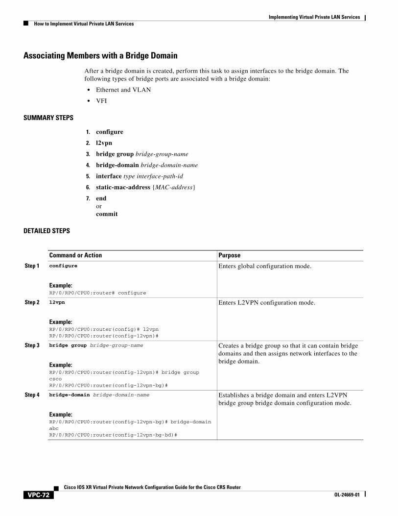
Associating Members with a Bridge Domain
After a bridge domain is created, perform this task to assign interfaces to the bridge domain. The following types of bridge ports are associated with a bridge domain:
• Ethernet and VLAN
• VFI
SUMMARY STEPS
1. configure
2. l2vpn
3. bridge group bridge-group-name
4. bridge-domain bridge-domain-name
5. interface type interface-path-id
6. static-mac-address {MAC-address}
7. endorcommit
DETAILED STEPS
Command or Action Purpose
Step 1 configure
Example:RP/0/RP0/CPU0:router# configure
Enters global configuration mode.
Step 2 l2vpn
Example:RP/0/RP0/CPU0:router(config)# l2vpnRP/0/RP0/CPU0:router(config-l2vpn)#
Enters L2VPN configuration mode.
Step 3 bridge group bridge-group-name
Example:RP/0/RP0/CPU0:router(config-l2vpn)# bridge group cscoRP/0/RP0/CPU0:router(config-l2vpn-bg)#
Creates a bridge group so that it can contain bridge domains and then assigns network interfaces to the bridge domain.
Step 4 bridge-domain bridge-domain-name
Example:RP/0/RP0/CPU0:router(config-l2vpn-bg)# bridge-domain abcRP/0/RP0/CPU0:router(config-l2vpn-bg-bd)#
Establishes a bridge domain and enters L2VPN bridge group bridge domain configuration mode.
VPC-72Cisco IOS XR Virtual Private Network Configuration Guide for the Cisco CRS Router
OL-24669-01
Implementing Virtual Private LAN ServicesHow to Implement Virtual Private LAN Services
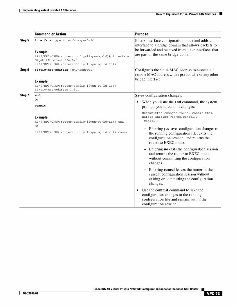
Step 5 interface type interface-path-id
Example:RP/0/RP0/CPU0:router(config-l2vpn-bg-bd)# interface GigabitEthernet 0/4/0/0RP/0/RP0/CPU0:router(config-l2vpn-bg-bd-ac)#
Enters interface configuration mode and adds an interface to a bridge domain that allows packets to be forwarded and received from other interfaces that are part of the same bridge domain.
Step 6 static-mac-address {MAC-address}
Example:RP/0/RP0/CPU0:router(config-l2vpn-bg-bd-ac)# static-mac-address 1.1.1
Configures the static MAC address to associate a remote MAC address with a pseudowire or any other bridge interface.
Step 7 end
or
commit
Example:RP/0/RP0/CPU0:router(config-l2vpn-bg-bd-ac)# end
or
RP/0/RP0/CPU0:router(config-l2vpn-bg-bd-ac)# commit
Saves configuration changes.
• When you issue the end command, the system prompts you to commit changes:
Uncommitted changes found, commit them before exiting(yes/no/cancel)?[cancel]:
– Entering yes saves configuration changes to the running configuration file, exits the configuration session, and returns the router to EXEC mode.
– Entering no exits the configuration session and returns the router to EXEC mode without committing the configuration changes.
– Entering cancel leaves the router in the current configuration session without exiting or committing the configuration changes.
• Use the commit command to save the configuration changes to the running configuration file and remain within the configuration session.
Command or Action Purpose
VPC-73Cisco IOS XR Virtual Private Network Configuration Guide for the Cisco CRS Router
OL-24669-01
Implementing Virtual Private LAN Services How to Implement Virtual Private LAN Services
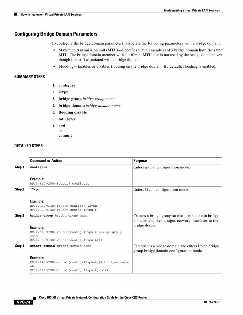
Configuring Bridge Domain Parameters
To configure the bridge domain parameters, associate the following parameters with a bridge domain:
• Maximum transmission unit (MTU)—Specifies that all members of a bridge domain have the same MTU. The bridge domain member with a different MTU size is not used by the bridge domain even though it is still associated with a bridge domain.
• Flooding—Enables or disables flooding on the bridge domain. By default, flooding is enabled.
SUMMARY STEPS
1. configure
2. l2vpn
3. bridge group bridge group name
4. bridge-domain bridge-domain name
5. flooding disable
6. mtu bytes
7. endorcommit
DETAILED STEPS
Command or Action Purpose
Step 1 configure
Example:RP/0/RP0/CPU0:router# configure
Enters global configuration mode.
Step 2 l2vpn
Example:RP/0/RP0/CPU0:router(config)# l2vpnRP/0/RP0/CPU0:router(config-l2vpn)#
Enters l2vpn configuration mode.
Step 3 bridge group bridge group name
Example:RP/0/RP0/CPU0:router(config-l2vpn)# bridge group cscoRP/0/RP0/CPU0:router(config-l2vpn-bg)#
Creates a bridge group so that it can contain bridge domains and then assigns network interfaces to the bridge domain.
Step 4 bridge-domain bridge-domain name
Example:RP/0/RP0/CPU0:router(config-l2vpn-bg)# bridge-domain abcRP/0/RP0/CPU0:router(config-l2vpn-bg-bd)#
Establishes a bridge domain and enters l2vpn bridge group bridge domain configuration mode.
VPC-74Cisco IOS XR Virtual Private Network Configuration Guide for the Cisco CRS Router
OL-24669-01
Implementing Virtual Private LAN ServicesHow to Implement Virtual Private LAN Services
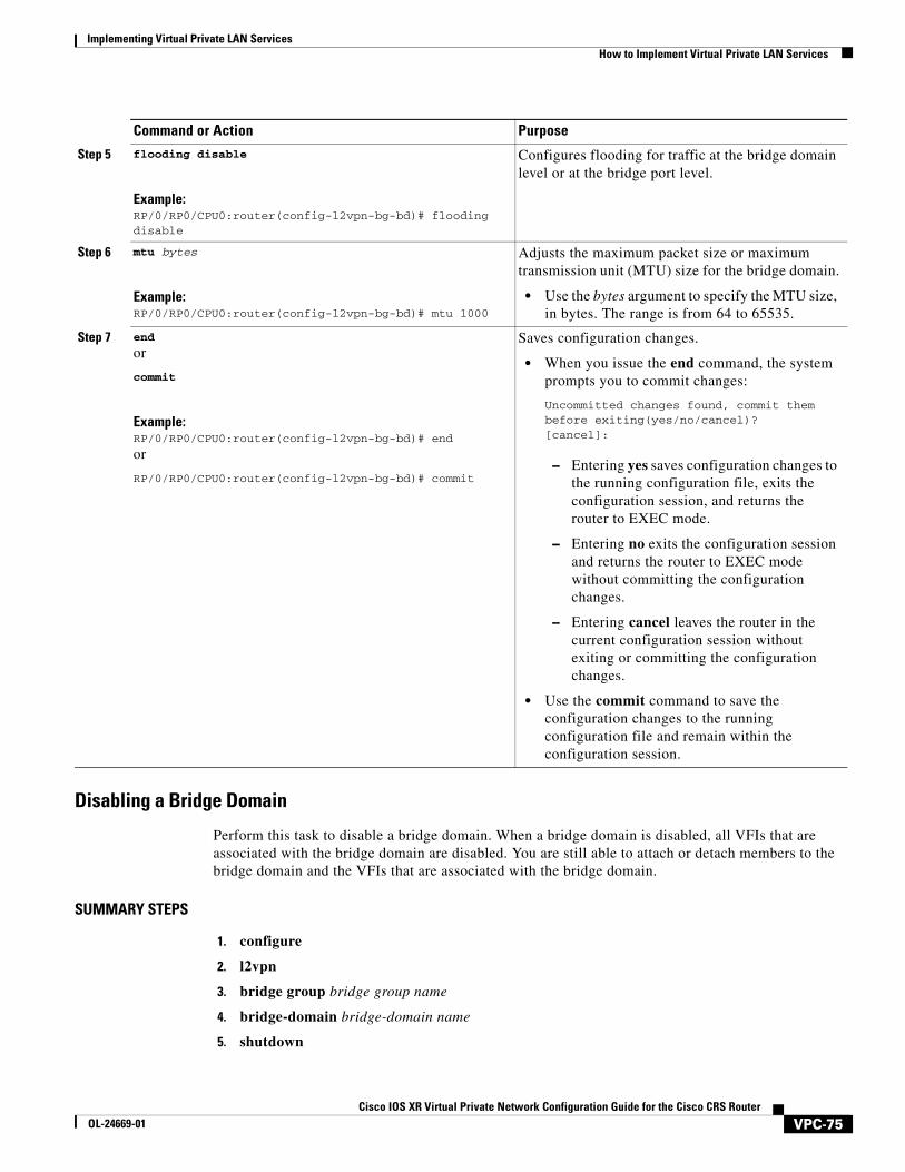
Disabling a Bridge Domain
Perform this task to disable a bridge domain. When a bridge domain is disabled, all VFIs that are associated with the bridge domain are disabled. You are still able to attach or detach members to the bridge domain and the VFIs that are associated with the bridge domain.
SUMMARY STEPS
1. configure
2. l2vpn
3. bridge group bridge group name
4. bridge-domain bridge-domain name
5. shutdown
Step 5 flooding disable
Example:RP/0/RP0/CPU0:router(config-l2vpn-bg-bd)# flooding disable
Configures flooding for traffic at the bridge domain level or at the bridge port level.
Step 6 mtu bytes
Example:RP/0/RP0/CPU0:router(config-l2vpn-bg-bd)# mtu 1000
Adjusts the maximum packet size or maximum transmission unit (MTU) size for the bridge domain.
• Use the bytes argument to specify the MTU size, in bytes. The range is from 64 to 65535.
Step 7 end
or
commit
Example:RP/0/RP0/CPU0:router(config-l2vpn-bg-bd)# end
or
RP/0/RP0/CPU0:router(config-l2vpn-bg-bd)# commit
Saves configuration changes.
• When you issue the end command, the system prompts you to commit changes:
Uncommitted changes found, commit them before exiting(yes/no/cancel)?[cancel]:
– Entering yes saves configuration changes to the running configuration file, exits the configuration session, and returns the router to EXEC mode.
– Entering no exits the configuration session and returns the router to EXEC mode without committing the configuration changes.
– Entering cancel leaves the router in the current configuration session without exiting or committing the configuration changes.
• Use the commit command to save the configuration changes to the running configuration file and remain within the configuration session.
Command or Action Purpose
VPC-75Cisco IOS XR Virtual Private Network Configuration Guide for the Cisco CRS Router
OL-24669-01
Implementing Virtual Private LAN Services How to Implement Virtual Private LAN Services
6. endorcommit
DETAILED STEPS
Command or Action Purpose
Step 1 configure
Example:RP/0/RP0/CPU0:router# configure
Enters global configuration mode.
Step 2 l2vpn
Example:RP/0/RP0/CPU0:router(config)# l2vpnRP/0/RP0/CPU0:router(config-l2vpn)#
Enters L2VPN configuration mode.
Step 3 bridge group bridge-group-name
Example:RP/0/RP0/CPU0:router(config-l2vpn)# bridge group cscoRP/0/RP0/CPU0:router(config-l2vpn-bg)#
Creates a bridge group so that it can contain bridge domains and then assigns network interfaces to the bridge domain.
Step 4 bridge-domain bridge-domain-name
Example:RP/0/RP0/CPU0:router(config-l2vpn-bg)# bridge-domain abcRP/0/RP0/CPU0:router(config-l2vpn-bg-bd)#
Establishes a bridge domain and enters l2vpn bridge group bridge domain configuration mode.
VPC-76Cisco IOS XR Virtual Private Network Configuration Guide for the Cisco CRS Router
OL-24669-01

Implementing Virtual Private LAN ServicesHow to Implement Virtual Private LAN Services
Configuring a Layer 2 Virtual Forwarding InstanceThese topics describe how to configure a Layer 2 virtual forwarding instance (VFI):
• Adding the Virtual Forwarding Instance Under the Bridge Domain, page VPC-78
• Associating Pseudowires with the Virtual Forwarding Instance, page VPC-79
• Associating a Virtual Forwarding Instance to a Bridge Domain, page VPC-81
• Attaching Pseudowire Classes to Pseudowires, page VPC-83
• Configuring Any Transport over Multiprotocol Pseudowires By Using Static Labels, page VPC-85
• Disabling a Virtual Forwarding Instance, page VPC-87
Step 5 shutdown
Example:RP/0/RP0/CPU0:router(config-l2vpn-bg-bd)#
Shuts down a bridge domain to bring the bridge and all attachment circuits and pseudowires under it to admin down state.
Step 6 end
or
commit
Example:RP/0/RP0/CPU0:router(config-l2vpn-bg-bd)# end
or
RP/0/RP0/CPU0:router(config-l2vpn-bg-bd)# commit
Saves configuration changes.
• When you issue the end command, the system prompts you to commit changes:
Uncommitted changes found, commit them before exiting(yes/no/cancel)?[cancel]:
– Entering yes saves configuration changes to the running configuration file, exits the configuration session, and returns the router to EXEC mode.
– Entering no exits the configuration session and returns the router to EXEC mode without committing the configuration changes.
– Entering cancel leaves the router in the current configuration session without exiting or committing the configuration changes.
• Use the commit command to save the configuration changes to the running configuration file and remain within the configuration session.
Command or Action Purpose
VPC-77Cisco IOS XR Virtual Private Network Configuration Guide for the Cisco CRS Router
OL-24669-01
Implementing Virtual Private LAN Services How to Implement Virtual Private LAN Services
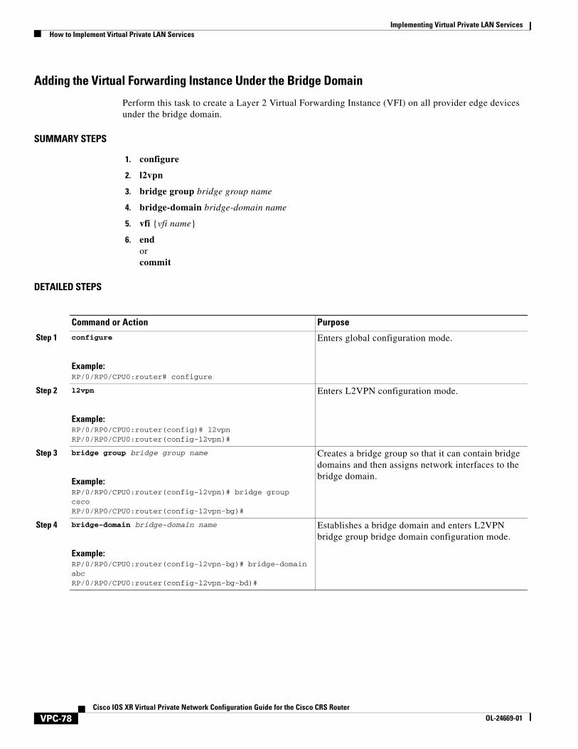
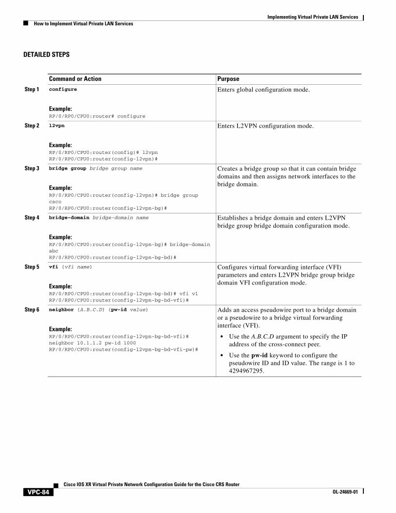
Adding the Virtual Forwarding Instance Under the Bridge Domain
Perform this task to create a Layer 2 Virtual Forwarding Instance (VFI) on all provider edge devices under the bridge domain.
SUMMARY STEPS
1. configure
2. l2vpn
3. bridge group bridge group name
4. bridge-domain bridge-domain name
5. vfi {vfi name}
6. endorcommit
DETAILED STEPS
Command or Action Purpose
Step 1 configure
Example:RP/0/RP0/CPU0:router# configure
Enters global configuration mode.
Step 2 l2vpn
Example:RP/0/RP0/CPU0:router(config)# l2vpnRP/0/RP0/CPU0:router(config-l2vpn)#
Enters L2VPN configuration mode.
Step 3 bridge group bridge group name
Example:RP/0/RP0/CPU0:router(config-l2vpn)# bridge group cscoRP/0/RP0/CPU0:router(config-l2vpn-bg)#
Creates a bridge group so that it can contain bridge domains and then assigns network interfaces to the bridge domain.
Step 4 bridge-domain bridge-domain name
Example:RP/0/RP0/CPU0:router(config-l2vpn-bg)# bridge-domain abcRP/0/RP0/CPU0:router(config-l2vpn-bg-bd)#
Establishes a bridge domain and enters L2VPN bridge group bridge domain configuration mode.
VPC-78Cisco IOS XR Virtual Private Network Configuration Guide for the Cisco CRS Router
OL-24669-01
Implementing Virtual Private LAN ServicesHow to Implement Virtual Private LAN Services
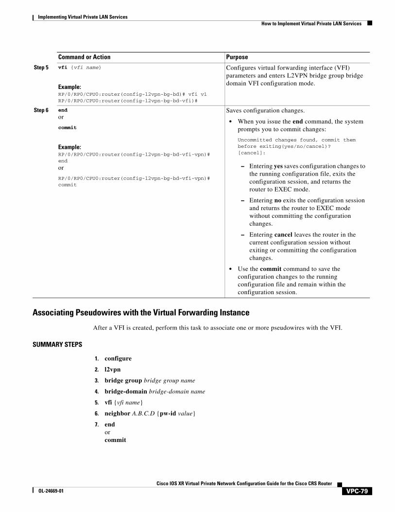
Associating Pseudowires with the Virtual Forwarding Instance
After a VFI is created, perform this task to associate one or more pseudowires with the VFI.
SUMMARY STEPS
1. configure
2. l2vpn
3. bridge group bridge group name
4. bridge-domain bridge-domain name
5. vfi {vfi name}
6. neighbor A.B.C.D {pw-id value}
7. endorcommit
Step 5 vfi {vfi name}
Example:RP/0/RP0/CPU0:router(config-l2vpn-bg-bd)# vfi v1RP/0/RP0/CPU0:router(config-l2vpn-bg-bd-vfi)#
Configures virtual forwarding interface (VFI) parameters and enters L2VPN bridge group bridge domain VFI configuration mode.
Step 6 end
or
commit
Example:RP/0/RP0/CPU0:router(config-l2vpn-bg-bd-vfi-vpn)# end
or
RP/0/RP0/CPU0:router(config-l2vpn-bg-bd-vfi-vpn)# commit
Saves configuration changes.
• When you issue the end command, the system prompts you to commit changes:
Uncommitted changes found, commit them before exiting(yes/no/cancel)?[cancel]:
– Entering yes saves configuration changes to the running configuration file, exits the configuration session, and returns the router to EXEC mode.
– Entering no exits the configuration session and returns the router to EXEC mode without committing the configuration changes.
– Entering cancel leaves the router in the current configuration session without exiting or committing the configuration changes.
• Use the commit command to save the configuration changes to the running configuration file and remain within the configuration session.
Command or Action Purpose
VPC-79Cisco IOS XR Virtual Private Network Configuration Guide for the Cisco CRS Router
OL-24669-01
Implementing Virtual Private LAN Services How to Implement Virtual Private LAN Services
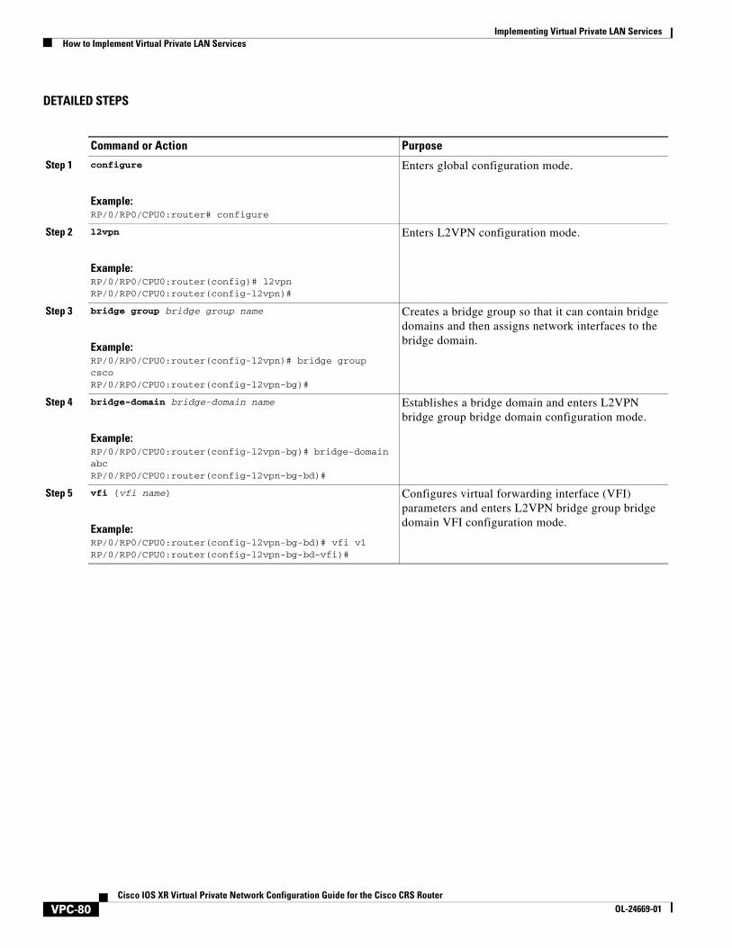
DETAILED STEPS
Command or Action Purpose
Step 1 configure
Example:RP/0/RP0/CPU0:router# configure
Enters global configuration mode.
Step 2 l2vpn
Example:RP/0/RP0/CPU0:router(config)# l2vpnRP/0/RP0/CPU0:router(config-l2vpn)#
Enters L2VPN configuration mode.
Step 3 bridge group bridge group name
Example:RP/0/RP0/CPU0:router(config-l2vpn)# bridge group cscoRP/0/RP0/CPU0:router(config-l2vpn-bg)#
Creates a bridge group so that it can contain bridge domains and then assigns network interfaces to the bridge domain.
Step 4 bridge-domain bridge-domain name
Example:RP/0/RP0/CPU0:router(config-l2vpn-bg)# bridge-domain abcRP/0/RP0/CPU0:router(config-l2vpn-bg-bd)#
Establishes a bridge domain and enters L2VPN bridge group bridge domain configuration mode.
Step 5 vfi {vfi name}
Example:RP/0/RP0/CPU0:router(config-l2vpn-bg-bd)# vfi v1RP/0/RP0/CPU0:router(config-l2vpn-bg-bd-vfi)#
Configures virtual forwarding interface (VFI) parameters and enters L2VPN bridge group bridge domain VFI configuration mode.
VPC-80Cisco IOS XR Virtual Private Network Configuration Guide for the Cisco CRS Router
OL-24669-01
Implementing Virtual Private LAN ServicesHow to Implement Virtual Private LAN Services
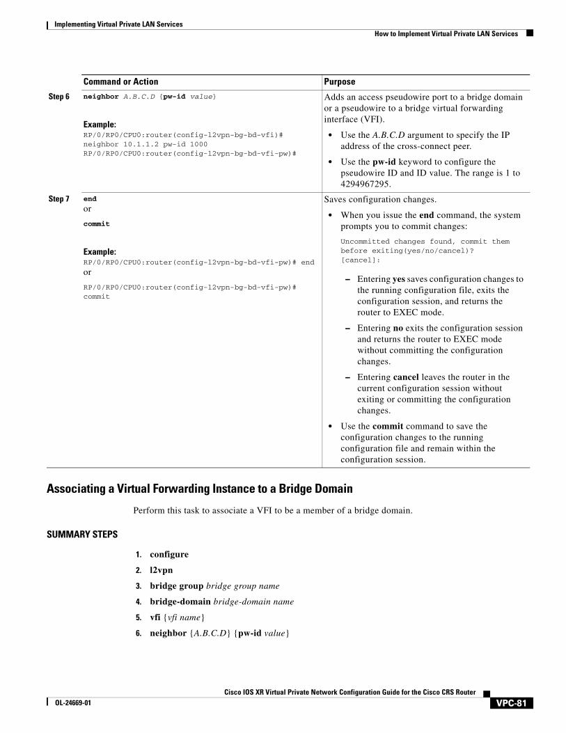
Associating a Virtual Forwarding Instance to a Bridge Domain
Perform this task to associate a VFI to be a member of a bridge domain.
SUMMARY STEPS
1. configure
2. l2vpn
3. bridge group bridge group name
4. bridge-domain bridge-domain name
5. vfi {vfi name}
6. neighbor {A.B.C.D} {pw-id value}
Step 6 neighbor A.B.C.D {pw-id value}
Example:RP/0/RP0/CPU0:router(config-l2vpn-bg-bd-vfi)# neighbor 10.1.1.2 pw-id 1000RP/0/RP0/CPU0:router(config-l2vpn-bg-bd-vfi-pw)#
Adds an access pseudowire port to a bridge domain or a pseudowire to a bridge virtual forwarding interface (VFI).
• Use the A.B.C.D argument to specify the IP address of the cross-connect peer.
• Use the pw-id keyword to configure the pseudowire ID and ID value. The range is 1 to 4294967295.
Step 7 end
or
commit
Example:RP/0/RP0/CPU0:router(config-l2vpn-bg-bd-vfi-pw)# end
or
RP/0/RP0/CPU0:router(config-l2vpn-bg-bd-vfi-pw)# commit
Saves configuration changes.
• When you issue the end command, the system prompts you to commit changes:
Uncommitted changes found, commit them before exiting(yes/no/cancel)?[cancel]:
– Entering yes saves configuration changes to the running configuration file, exits the configuration session, and returns the router to EXEC mode.
– Entering no exits the configuration session and returns the router to EXEC mode without committing the configuration changes.
– Entering cancel leaves the router in the current configuration session without exiting or committing the configuration changes.
• Use the commit command to save the configuration changes to the running configuration file and remain within the configuration session.
Command or Action Purpose
VPC-81Cisco IOS XR Virtual Private Network Configuration Guide for the Cisco CRS Router
OL-24669-01

Implementing Virtual Private LAN Services How to Implement Virtual Private LAN Services
7. static-mac-address {MAC address}
8. endorcommit
DETAILED STEPS
Command or Action Purpose
Step 1 configure
Example:RP/0/RP0/CPU0:router# configure
Enters global configuration mode.
Step 2 l2vpn
Example:RP/0/RP0/CPU0:router(config)# l2vpnRP/0/RP0/CPU0:router(config-l2vpn)#
Enters L2VPN configuration mode.
Step 3 bridge group bridge group name
Example:RP/0/RP0/CPU0:router(config-l2vpn)# bridge group cscoRP/0/RP0/CPU0:router(config-l2vpn-bg)#
Creates a bridge group so that it can contain bridge domains and then assigns network interfaces to the bridge domain.
Step 4 bridge-domain bridge-domain name
Example:RP/0/RP0/CPU0:router(config-l2vpn-bg)# bridge-domain abcRP/0/RP0/CPU0:router(config-l2vpn-bg-bd)#
Establishes a bridge domain and enters L2VPN bridge group bridge domain configuration mode.
Step 5 vfi vfi name
Example:RP/0/RP0/CPU0:router(config-l2vpn-bg-bd)# vfi v1RP/0/RP0/CPU0:router(config-l2vpn-bg-bd-vfi)#
Configures virtual forwarding interface (VFI) parameters and enters L2VPN bridge group bridge domain VFI configuration mode.
Step 6 neighbor A.B.C.D {pw-id value}
Example:RP/0/RP0/CPU0:router(config-l2vpn-bg-bd-vfi)# neighbor 10.1.1.2 pw-id 1000RP/0/RP0/CPU0:router(config-l2vpn-bg-bd-vfi-pw)#
Adds an access pseudowire port to a bridge domain or a pseudowire to a bridge virtual forwarding interface (VFI).
• Use the A.B.C.D argument to specify the IP address of the cross-connect peer.
• Use the pw-id keyword to configure the pseudowire ID and ID value. The range is 1 to 4294967295.
VPC-82Cisco IOS XR Virtual Private Network Configuration Guide for the Cisco CRS Router
OL-24669-01
Implementing Virtual Private LAN ServicesHow to Implement Virtual Private LAN Services
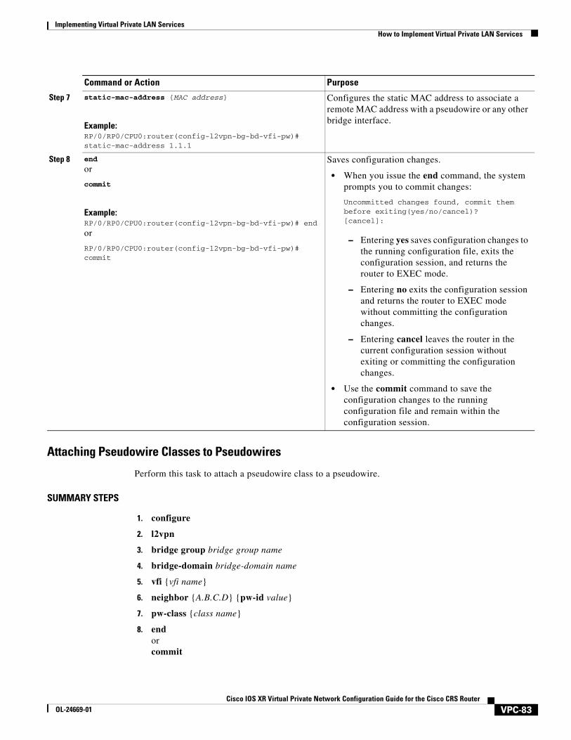
Attaching Pseudowire Classes to Pseudowires
Perform this task to attach a pseudowire class to a pseudowire.
SUMMARY STEPS
1. configure
2. l2vpn
3. bridge group bridge group name
4. bridge-domain bridge-domain name
5. vfi {vfi name}
6. neighbor {A.B.C.D} {pw-id value}
7. pw-class {class name}
8. endorcommit
Step 7 static-mac-address {MAC address}
Example:RP/0/RP0/CPU0:router(config-l2vpn-bg-bd-vfi-pw)# static-mac-address 1.1.1
Configures the static MAC address to associate a remote MAC address with a pseudowire or any other bridge interface.
Step 8 end
or
commit
Example:RP/0/RP0/CPU0:router(config-l2vpn-bg-bd-vfi-pw)# end
or
RP/0/RP0/CPU0:router(config-l2vpn-bg-bd-vfi-pw)# commit
Saves configuration changes.
• When you issue the end command, the system prompts you to commit changes:
Uncommitted changes found, commit them before exiting(yes/no/cancel)?[cancel]:
– Entering yes saves configuration changes to the running configuration file, exits the configuration session, and returns the router to EXEC mode.
– Entering no exits the configuration session and returns the router to EXEC mode without committing the configuration changes.
– Entering cancel leaves the router in the current configuration session without exiting or committing the configuration changes.
• Use the commit command to save the configuration changes to the running configuration file and remain within the configuration session.
Command or Action Purpose
VPC-83Cisco IOS XR Virtual Private Network Configuration Guide for the Cisco CRS Router
OL-24669-01
Implementing Virtual Private LAN Services How to Implement Virtual Private LAN Services
DETAILED STEPS
Command or Action Purpose
Step 1 configure
Example:RP/0/RP0/CPU0:router# configure
Enters global configuration mode.
Step 2 l2vpn
Example:RP/0/RP0/CPU0:router(config)# l2vpnRP/0/RP0/CPU0:router(config-l2vpn)#
Enters L2VPN configuration mode.
Step 3 bridge group bridge group name
Example:RP/0/RP0/CPU0:router(config-l2vpn)# bridge group cscoRP/0/RP0/CPU0:router(config-l2vpn-bg)#
Creates a bridge group so that it can contain bridge domains and then assigns network interfaces to the bridge domain.
Step 4 bridge-domain bridge-domain name
Example:RP/0/RP0/CPU0:router(config-l2vpn-bg)# bridge-domain abcRP/0/RP0/CPU0:router(config-l2vpn-bg-bd)#
Establishes a bridge domain and enters L2VPN bridge group bridge domain configuration mode.
Step 5 vfi {vfi name}
Example:RP/0/RP0/CPU0:router(config-l2vpn-bg-bd)# vfi v1RP/0/RP0/CPU0:router(config-l2vpn-bg-bd-vfi)#
Configures virtual forwarding interface (VFI) parameters and enters L2VPN bridge group bridge domain VFI configuration mode.
Step 6 neighbor {A.B.C.D} {pw-id value}
Example:RP/0/RP0/CPU0:router(config-l2vpn-bg-bd-vfi)# neighbor 10.1.1.2 pw-id 1000RP/0/RP0/CPU0:router(config-l2vpn-bg-bd-vfi-pw)#
Adds an access pseudowire port to a bridge domain or a pseudowire to a bridge virtual forwarding interface (VFI).
• Use the A.B.C.D argument to specify the IP address of the cross-connect peer.
• Use the pw-id keyword to configure the pseudowire ID and ID value. The range is 1 to 4294967295.
VPC-84Cisco IOS XR Virtual Private Network Configuration Guide for the Cisco CRS Router
OL-24669-01

Implementing Virtual Private LAN ServicesHow to Implement Virtual Private LAN Services
Configuring Any Transport over Multiprotocol Pseudowires By Using Static Labels
Perform this task to configure the Any Transport over Multiprotocol (AToM) pseudowires by using the static labels. A pseudowire becomes a static AToM pseudowire by setting the MPLS static labels to local and remote.
SUMMARY STEPS
1. configure
2. l2vpn
3. bridge group bridge group name
4. bridge-domain bridge-domain name
5. vfi {vfi name}
6. neighbor {A.B.C.D} {pw-id value}
Step 7 pw-class {class name}
Example:RP/0/RP0/CPU0:router(config-l2vpn-bg-bd-vfi-pw)# pw-class canada
Configures the pseudowire class template name to use for the pseudowire.
Step 8 end
or
commit
Example:RP/0/RP0/CPU0:router(config-l2vpn-bg-bd-vfi-pw)# end
or
RP/0/RP0/CPU0:router(config-l2vpn-bg-bd-vfi-pw)# commit
Saves configuration changes.
• When you issue the end command, the system prompts you to commit changes:
Uncommitted changes found, commit them before exiting(yes/no/cancel)?[cancel]:
– Entering yes saves configuration changes to the running configuration file, exits the configuration session, and returns the router to EXEC mode.
– Entering no exits the configuration session and returns the router to EXEC mode without committing the configuration changes.
– Entering cancel leaves the router in the current configuration session without exiting or committing the configuration changes.
• Use the commit command to save the configuration changes to the running configuration file and remain within the configuration session.
Command or Action Purpose
VPC-85Cisco IOS XR Virtual Private Network Configuration Guide for the Cisco CRS Router
OL-24669-01
Implementing Virtual Private LAN Services How to Implement Virtual Private LAN Services
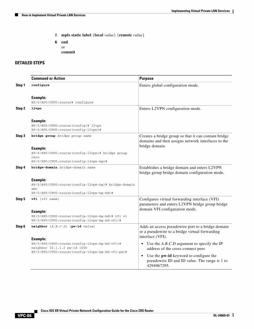
7. mpls static label {local value} {remote value}
8. endorcommit
DETAILED STEPS
Command or Action Purpose
Step 1 configure
Example:RP/0/RP0/CPU0:router# configure
Enters global configuration mode.
Step 2 l2vpn
Example:RP/0/RP0/CPU0:router(config)# l2vpnRP/0/RP0/CPU0:router(config-l2vpn)#
Enters L2VPN configuration mode.
Step 3 bridge group bridge group name
Example:RP/0/RP0/CPU0:router(config-l2vpn)# bridge group cscoRP/0/RP0/CPU0:router(config-l2vpn-bg)#
Creates a bridge group so that it can contain bridge domains and then assigns network interfaces to the bridge domain.
Step 4 bridge-domain bridge-domain name
Example:RP/0/RP0/CPU0:router(config-l2vpn-bg)# bridge-domain abcRP/0/RP0/CPU0:router(config-l2vpn-bg-bd)#
Establishes a bridge domain and enters L2VPN bridge group bridge domain configuration mode.
Step 5 vfi {vfi name}
Example:RP/0/RP0/CPU0:router(config-l2vpn-bg-bd)# vfi v1RP/0/RP0/CPU0:router(config-l2vpn-bg-bd-vfi)#
Configures virtual forwarding interface (VFI) parameters and enters L2VPN bridge group bridge domain VFI configuration mode.
Step 6 neighbor {A.B.C.D} {pw-id value}
Example:RP/0/RP0/CPU0:router(config-l2vpn-bg-bd-vfi)# neighbor 10.1.1.2 pw-id 1000RP/0/RP0/CPU0:router(config-l2vpn-bg-bd-vfi-pw)#
Adds an access pseudowire port to a bridge domain or a pseudowire to a bridge virtual forwarding interface (VFI).
• Use the A.B.C.D argument to specify the IP address of the cross-connect peer.
• Use the pw-id keyword to configure the pseudowire ID and ID value. The range is 1 to 4294967295.
VPC-86Cisco IOS XR Virtual Private Network Configuration Guide for the Cisco CRS Router
OL-24669-01
Implementing Virtual Private LAN ServicesHow to Implement Virtual Private LAN Services
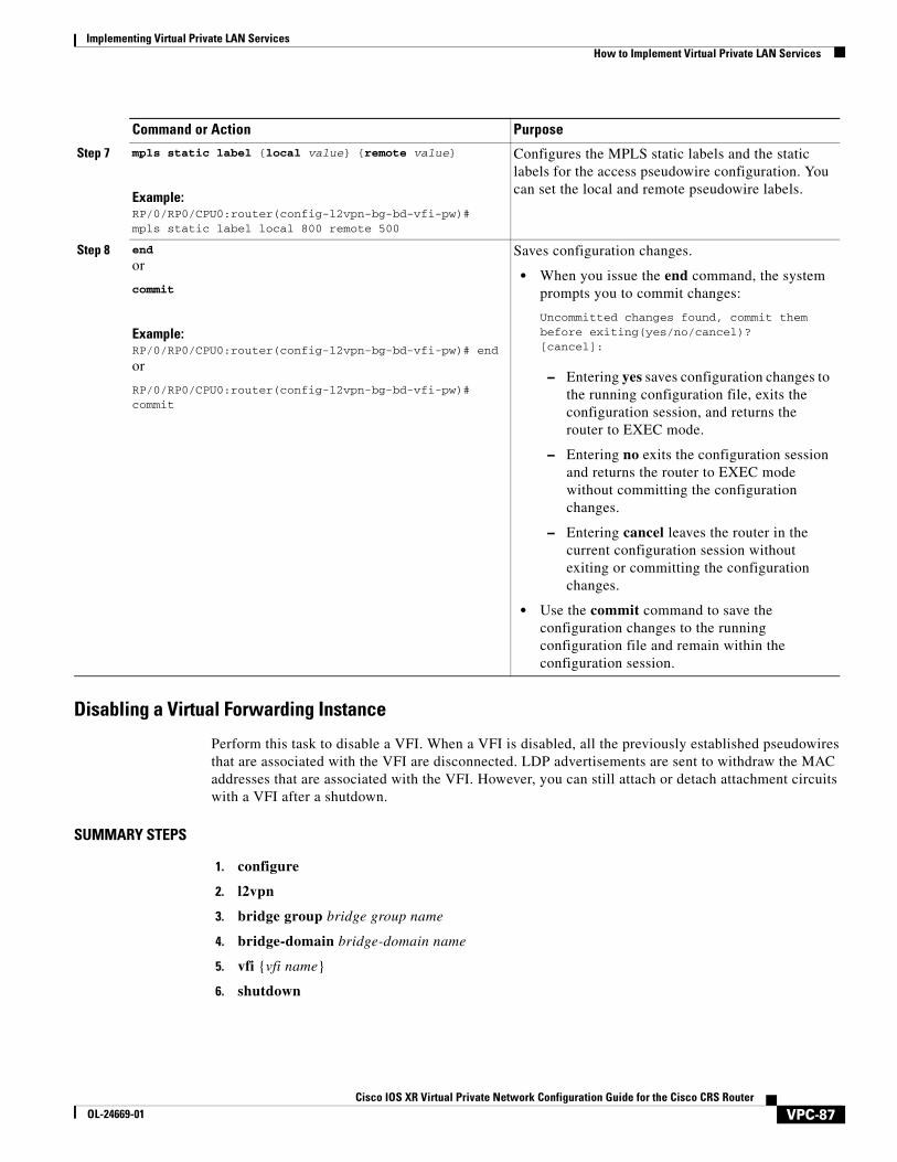
Disabling a Virtual Forwarding Instance
Perform this task to disable a VFI. When a VFI is disabled, all the previously established pseudowires that are associated with the VFI are disconnected. LDP advertisements are sent to withdraw the MAC addresses that are associated with the VFI. However, you can still attach or detach attachment circuits with a VFI after a shutdown.
SUMMARY STEPS
1. configure
2. l2vpn
3. bridge group bridge group name
4. bridge-domain bridge-domain name
5. vfi {vfi name}
6. shutdown
Step 7 mpls static label {local value} {remote value}
Example:RP/0/RP0/CPU0:router(config-l2vpn-bg-bd-vfi-pw)# mpls static label local 800 remote 500
Configures the MPLS static labels and the static labels for the access pseudowire configuration. You can set the local and remote pseudowire labels.
Step 8 end
or
commit
Example:RP/0/RP0/CPU0:router(config-l2vpn-bg-bd-vfi-pw)# end
or
RP/0/RP0/CPU0:router(config-l2vpn-bg-bd-vfi-pw)# commit
Saves configuration changes.
• When you issue the end command, the system prompts you to commit changes:
Uncommitted changes found, commit them before exiting(yes/no/cancel)?[cancel]:
– Entering yes saves configuration changes to the running configuration file, exits the configuration session, and returns the router to EXEC mode.
– Entering no exits the configuration session and returns the router to EXEC mode without committing the configuration changes.
– Entering cancel leaves the router in the current configuration session without exiting or committing the configuration changes.
• Use the commit command to save the configuration changes to the running configuration file and remain within the configuration session.
Command or Action Purpose
VPC-87Cisco IOS XR Virtual Private Network Configuration Guide for the Cisco CRS Router
OL-24669-01
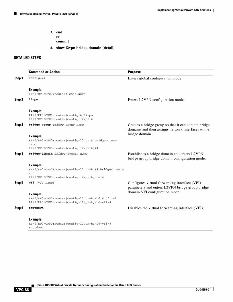
Implementing Virtual Private LAN Services How to Implement Virtual Private LAN Services
7. endorcommit
8. show l2vpn bridge-domain [detail]
DETAILED STEPS
Command or Action Purpose
Step 1 configure
Example:RP/0/RP0/CPU0:router# configure
Enters global configuration mode.
Step 2 l2vpn
Example:RP/0/RP0/CPU0:router(config)# l2vpnRP/0/RP0/CPU0:router(config-l2vpn)#
Enters L2VPN configuration mode.
Step 3 bridge group bridge group name
Example:RP/0/RP0/CPU0:router(config-l2vpn)# bridge group cscoRP/0/RP0/CPU0:router(config-l2vpn-bg)#
Creates a bridge group so that it can contain bridge domains and then assigns network interfaces to the bridge domain.
Step 4 bridge-domain bridge-domain name
Example:RP/0/RP0/CPU0:router(config-l2vpn-bg)# bridge-domain abcRP/0/RP0/CPU0:router(config-l2vpn-bg-bd)#
Establishes a bridge domain and enters L2VPN bridge group bridge domain configuration mode.
Step 5 vfi {vfi name}
Example:RP/0/RP0/CPU0:router(config-l2vpn-bg-bd)# vfi v1RP/0/RP0/CPU0:router(config-l2vpn-bg-bd-vfi)#
Configures virtual forwarding interface (VFI) parameters and enters L2VPN bridge group bridge domain VFI configuration mode.
Step 6 shutdown
Example:RP/0/RP0/CPU0:router(config-l2vpn-bg-bd-vfi)# shutdown
Disables the virtual forwarding interface (VFI).
VPC-88Cisco IOS XR Virtual Private Network Configuration Guide for the Cisco CRS Router
OL-24669-01
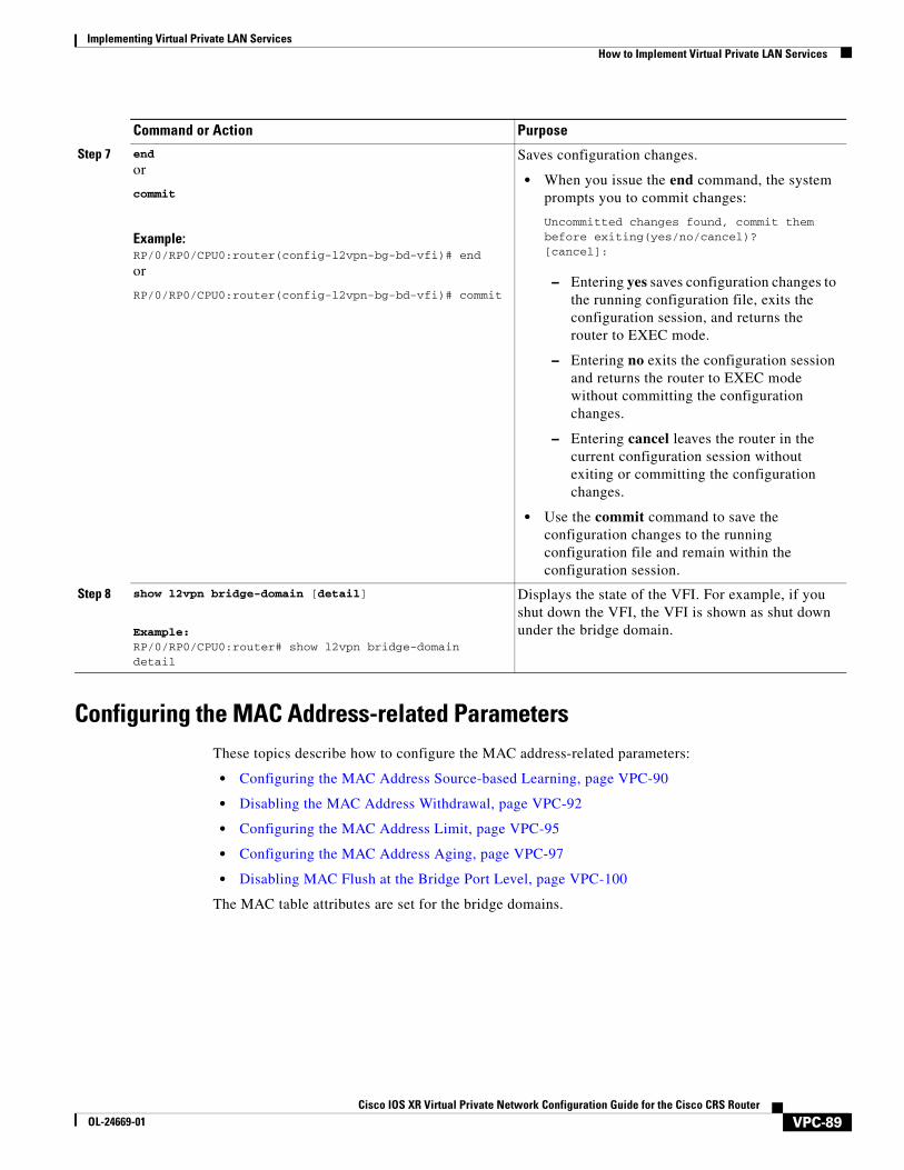
Implementing Virtual Private LAN ServicesHow to Implement Virtual Private LAN Services
Configuring the MAC Address-related ParametersThese topics describe how to configure the MAC address-related parameters:
• Configuring the MAC Address Source-based Learning, page VPC-90
• Disabling the MAC Address Withdrawal, page VPC-92
• Configuring the MAC Address Limit, page VPC-95
• Configuring the MAC Address Aging, page VPC-97
• Disabling MAC Flush at the Bridge Port Level, page VPC-100
The MAC table attributes are set for the bridge domains.
Step 7 end
or
commit
Example:RP/0/RP0/CPU0:router(config-l2vpn-bg-bd-vfi)# end
or
RP/0/RP0/CPU0:router(config-l2vpn-bg-bd-vfi)# commit
Saves configuration changes.
• When you issue the end command, the system prompts you to commit changes:
Uncommitted changes found, commit them before exiting(yes/no/cancel)?[cancel]:
– Entering yes saves configuration changes to the running configuration file, exits the configuration session, and returns the router to EXEC mode.
– Entering no exits the configuration session and returns the router to EXEC mode without committing the configuration changes.
– Entering cancel leaves the router in the current configuration session without exiting or committing the configuration changes.
• Use the commit command to save the configuration changes to the running configuration file and remain within the configuration session.
Step 8 show l2vpn bridge-domain [detail]
Example:RP/0/RP0/CPU0:router# show l2vpn bridge-domain detail
Displays the state of the VFI. For example, if you shut down the VFI, the VFI is shown as shut down under the bridge domain.
Command or Action Purpose
VPC-89Cisco IOS XR Virtual Private Network Configuration Guide for the Cisco CRS Router
OL-24669-01
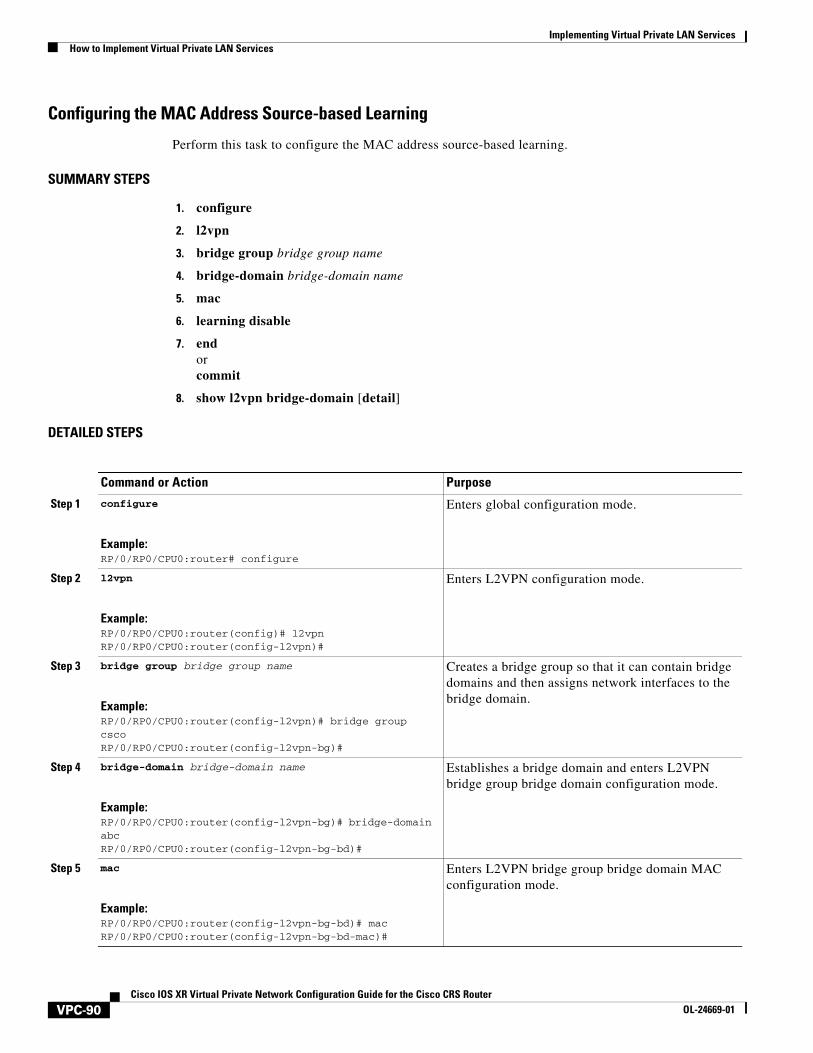
Implementing Virtual Private LAN Services How to Implement Virtual Private LAN Services
Configuring the MAC Address Source-based Learning
Perform this task to configure the MAC address source-based learning.
SUMMARY STEPS
1. configure
2. l2vpn
3. bridge group bridge group name
4. bridge-domain bridge-domain name
5. mac
6. learning disable
7. endorcommit
8. show l2vpn bridge-domain [detail]
DETAILED STEPS
Command or Action Purpose
Step 1 configure
Example:RP/0/RP0/CPU0:router# configure
Enters global configuration mode.
Step 2 l2vpn
Example:RP/0/RP0/CPU0:router(config)# l2vpnRP/0/RP0/CPU0:router(config-l2vpn)#
Enters L2VPN configuration mode.
Step 3 bridge group bridge group name
Example:RP/0/RP0/CPU0:router(config-l2vpn)# bridge group cscoRP/0/RP0/CPU0:router(config-l2vpn-bg)#
Creates a bridge group so that it can contain bridge domains and then assigns network interfaces to the bridge domain.
Step 4 bridge-domain bridge-domain name
Example:RP/0/RP0/CPU0:router(config-l2vpn-bg)# bridge-domain abcRP/0/RP0/CPU0:router(config-l2vpn-bg-bd)#
Establishes a bridge domain and enters L2VPN bridge group bridge domain configuration mode.
Step 5 mac
Example:RP/0/RP0/CPU0:router(config-l2vpn-bg-bd)# macRP/0/RP0/CPU0:router(config-l2vpn-bg-bd-mac)#
Enters L2VPN bridge group bridge domain MAC configuration mode.
VPC-90Cisco IOS XR Virtual Private Network Configuration Guide for the Cisco CRS Router
OL-24669-01
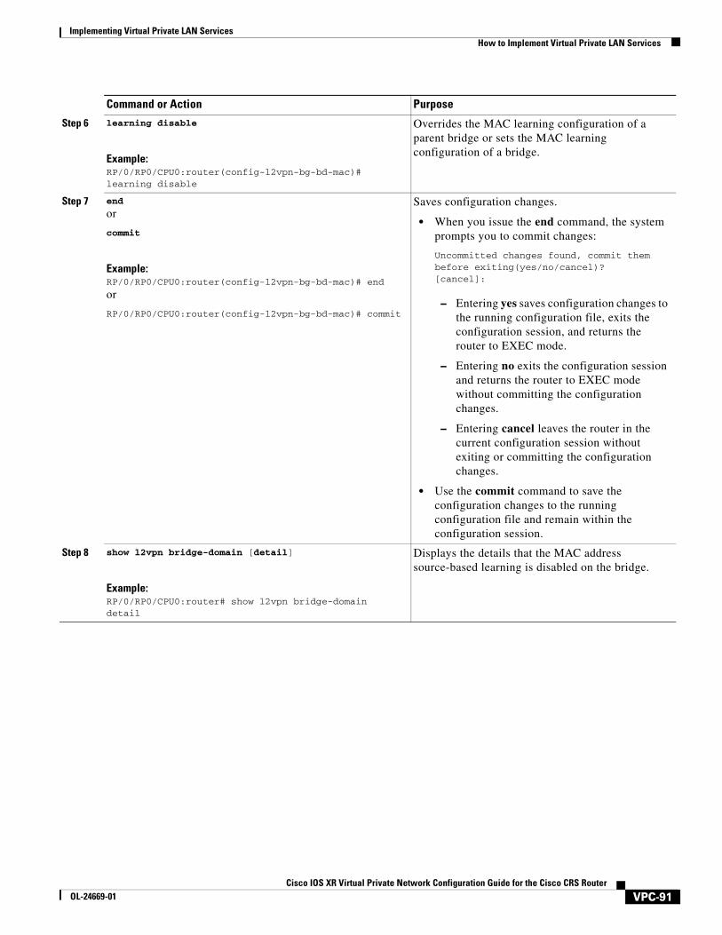
Implementing Virtual Private LAN ServicesHow to Implement Virtual Private LAN Services
Step 6 learning disable
Example:RP/0/RP0/CPU0:router(config-l2vpn-bg-bd-mac)# learning disable
Overrides the MAC learning configuration of a parent bridge or sets the MAC learning configuration of a bridge.
Step 7 end
or
commit
Example:RP/0/RP0/CPU0:router(config-l2vpn-bg-bd-mac)# end
or
RP/0/RP0/CPU0:router(config-l2vpn-bg-bd-mac)# commit
Saves configuration changes.
• When you issue the end command, the system prompts you to commit changes:
Uncommitted changes found, commit them before exiting(yes/no/cancel)?[cancel]:
– Entering yes saves configuration changes to the running configuration file, exits the configuration session, and returns the router to EXEC mode.
– Entering no exits the configuration session and returns the router to EXEC mode without committing the configuration changes.
– Entering cancel leaves the router in the current configuration session without exiting or committing the configuration changes.
• Use the commit command to save the configuration changes to the running configuration file and remain within the configuration session.
Step 8 show l2vpn bridge-domain [detail]
Example:RP/0/RP0/CPU0:router# show l2vpn bridge-domain detail
Displays the details that the MAC address source-based learning is disabled on the bridge.
Command or Action Purpose
VPC-91Cisco IOS XR Virtual Private Network Configuration Guide for the Cisco CRS Router
OL-24669-01
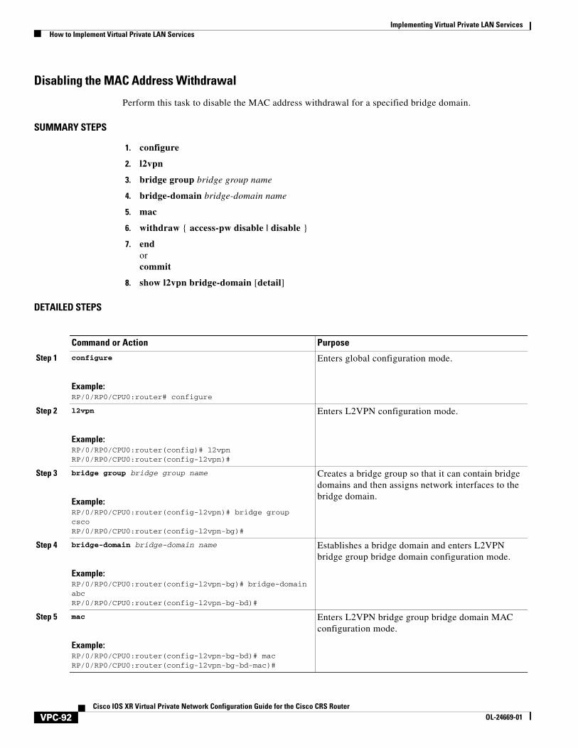
Implementing Virtual Private LAN Services How to Implement Virtual Private LAN Services
Disabling the MAC Address Withdrawal
Perform this task to disable the MAC address withdrawal for a specified bridge domain.
SUMMARY STEPS
1. configure
2. l2vpn
3. bridge group bridge group name
4. bridge-domain bridge-domain name
5. mac
6. withdraw { access-pw disable | disable }
7. endorcommit
8. show l2vpn bridge-domain [detail]
DETAILED STEPS
Command or Action Purpose
Step 1 configure
Example:RP/0/RP0/CPU0:router# configure
Enters global configuration mode.
Step 2 l2vpn
Example:RP/0/RP0/CPU0:router(config)# l2vpnRP/0/RP0/CPU0:router(config-l2vpn)#
Enters L2VPN configuration mode.
Step 3 bridge group bridge group name
Example:RP/0/RP0/CPU0:router(config-l2vpn)# bridge group cscoRP/0/RP0/CPU0:router(config-l2vpn-bg)#
Creates a bridge group so that it can contain bridge domains and then assigns network interfaces to the bridge domain.
Step 4 bridge-domain bridge-domain name
Example:RP/0/RP0/CPU0:router(config-l2vpn-bg)# bridge-domain abcRP/0/RP0/CPU0:router(config-l2vpn-bg-bd)#
Establishes a bridge domain and enters L2VPN bridge group bridge domain configuration mode.
Step 5 mac
Example:RP/0/RP0/CPU0:router(config-l2vpn-bg-bd)# macRP/0/RP0/CPU0:router(config-l2vpn-bg-bd-mac)#
Enters L2VPN bridge group bridge domain MAC configuration mode.
VPC-92Cisco IOS XR Virtual Private Network Configuration Guide for the Cisco CRS Router
OL-24669-01
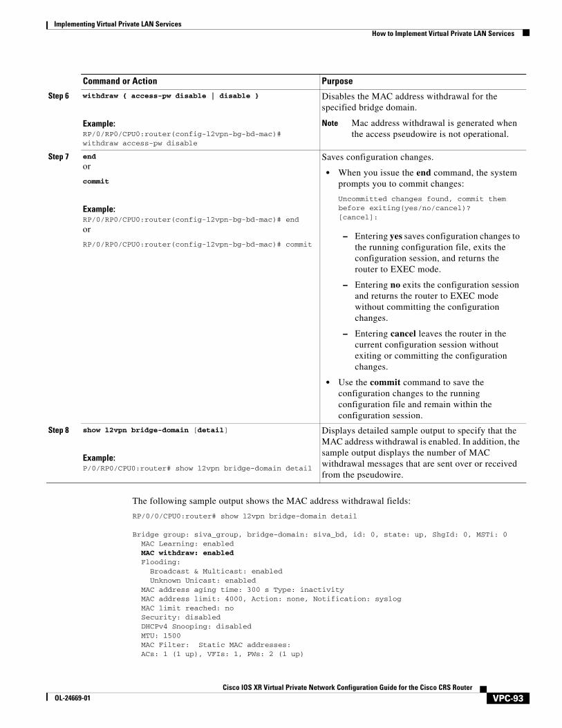
Implementing Virtual Private LAN ServicesHow to Implement Virtual Private LAN Services
The following sample output shows the MAC address withdrawal fields:
RP/0/0/CPU0:router# show l2vpn bridge-domain detail
Bridge group: siva_group, bridge-domain: siva_bd, id: 0, state: up, ShgId: 0, MSTi: 0 MAC Learning: enabled MAC withdraw: enabled Flooding: Broadcast & Multicast: enabled Unknown Unicast: enabled MAC address aging time: 300 s Type: inactivity MAC address limit: 4000, Action: none, Notification: syslog MAC limit reached: no Security: disabled DHCPv4 Snooping: disabled MTU: 1500 MAC Filter: Static MAC addresses: ACs: 1 (1 up), VFIs: 1, PWs: 2 (1 up)
Step 6 withdraw { access-pw disable | disable }
Example:RP/0/RP0/CPU0:router(config-l2vpn-bg-bd-mac)# withdraw access-pw disable
Disables the MAC address withdrawal for the specified bridge domain.
Note Mac address withdrawal is generated when the access pseudowire is not operational.
Step 7 end
or
commit
Example:RP/0/RP0/CPU0:router(config-l2vpn-bg-bd-mac)# end
or
RP/0/RP0/CPU0:router(config-l2vpn-bg-bd-mac)# commit
Saves configuration changes.
• When you issue the end command, the system prompts you to commit changes:
Uncommitted changes found, commit them before exiting(yes/no/cancel)?[cancel]:
– Entering yes saves configuration changes to the running configuration file, exits the configuration session, and returns the router to EXEC mode.
– Entering no exits the configuration session and returns the router to EXEC mode without committing the configuration changes.
– Entering cancel leaves the router in the current configuration session without exiting or committing the configuration changes.
• Use the commit command to save the configuration changes to the running configuration file and remain within the configuration session.
Step 8 show l2vpn bridge-domain [detail]
Example:P/0/RP0/CPU0:router# show l2vpn bridge-domain detail
Displays detailed sample output to specify that the MAC address withdrawal is enabled. In addition, the sample output displays the number of MAC withdrawal messages that are sent over or received from the pseudowire.
Command or Action Purpose
VPC-93Cisco IOS XR Virtual Private Network Configuration Guide for the Cisco CRS Router
OL-24669-01
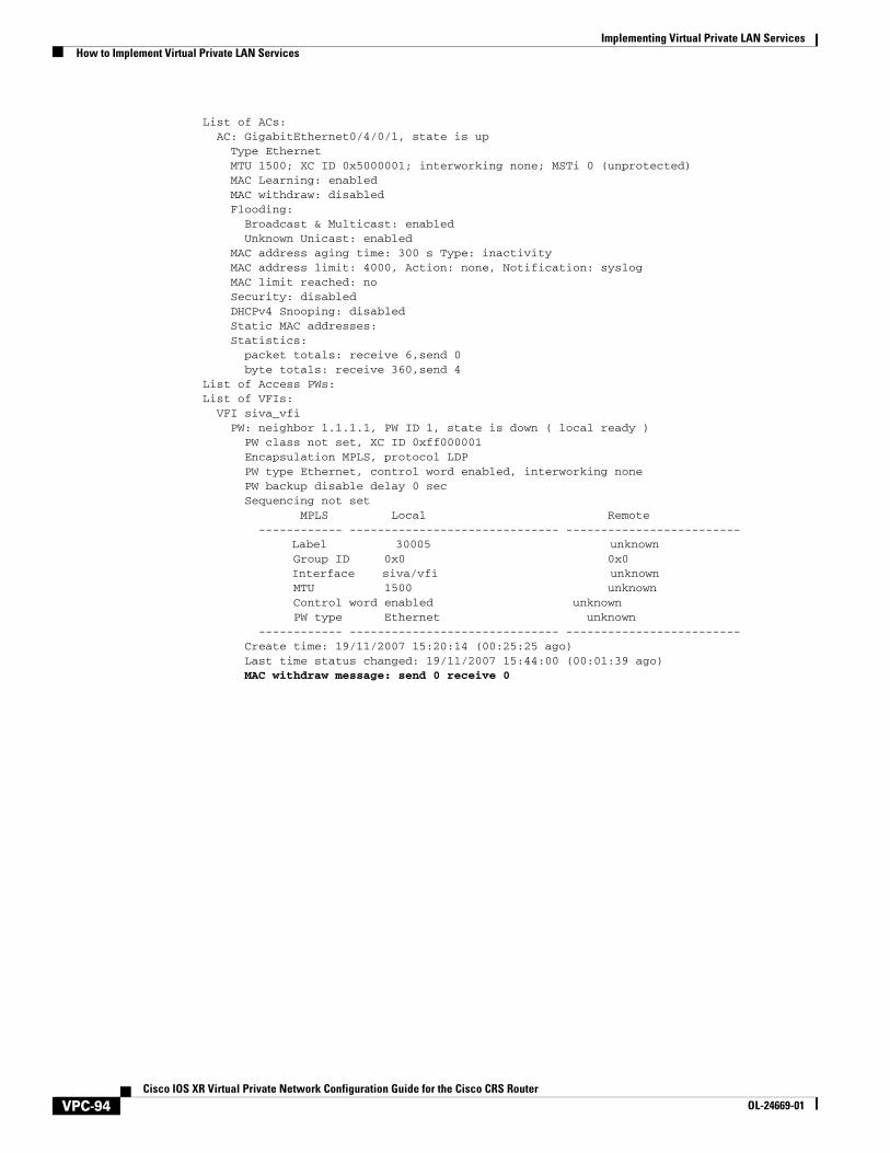
Implementing Virtual Private LAN Services How to Implement Virtual Private LAN Services
List of ACs: AC: GigabitEthernet0/4/0/1, state is up Type Ethernet MTU 1500; XC ID 0x5000001; interworking none; MSTi 0 (unprotected) MAC Learning: enabled MAC withdraw: disabled Flooding: Broadcast & Multicast: enabled Unknown Unicast: enabled MAC address aging time: 300 s Type: inactivity MAC address limit: 4000, Action: none, Notification: syslog MAC limit reached: no Security: disabled DHCPv4 Snooping: disabled Static MAC addresses: Statistics: packet totals: receive 6,send 0 byte totals: receive 360,send 4 List of Access PWs: List of VFIs: VFI siva_vfi PW: neighbor 1.1.1.1, PW ID 1, state is down ( local ready ) PW class not set, XC ID 0xff000001 Encapsulation MPLS, protocol LDP PW type Ethernet, control word enabled, interworking none PW backup disable delay 0 sec Sequencing not set MPLS Local Remote ------------ ------------------------------ ------------------------- Label 30005 unknown Group ID 0x0 0x0 Interface siva/vfi unknown MTU 1500 unknown Control word enabled unknown PW type Ethernet unknown ------------ ------------------------------ ------------------------- Create time: 19/11/2007 15:20:14 (00:25:25 ago) Last time status changed: 19/11/2007 15:44:00 (00:01:39 ago) MAC withdraw message: send 0 receive 0
VPC-94Cisco IOS XR Virtual Private Network Configuration Guide for the Cisco CRS Router
OL-24669-01
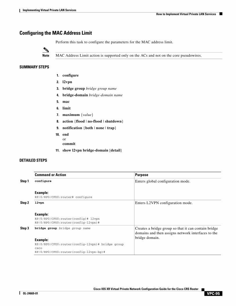
Implementing Virtual Private LAN ServicesHow to Implement Virtual Private LAN Services
Configuring the MAC Address Limit
Perform this task to configure the parameters for the MAC address limit.
Note MAC Address Limit action is supported only on the ACs and not on the core pseudowires.
SUMMARY STEPS
1. configure
2. l2vpn
3. bridge group bridge group name
4. bridge-domain bridge-domain name
5. mac
6. limit
7. maximum {value}
8. action {flood | no-flood | shutdown}
9. notification {both | none | trap}
10. endorcommit
11. show l2vpn bridge-domain [detail]
DETAILED STEPS
Command or Action Purpose
Step 1 configure
Example:RP/0/RP0/CPU0:router# configure
Enters global configuration mode.
Step 2 l2vpn
Example:RP/0/RP0/CPU0:router(config)# l2vpnRP/0/RP0/CPU0:router(config-l2vpn)#
Enters L2VPN configuration mode.
Step 3 bridge group bridge group name
Example:RP/0/RP0/CPU0:router(config-l2vpn)# bridge group cscoRP/0/RP0/CPU0:router(config-l2vpn-bg)#
Creates a bridge group so that it can contain bridge domains and then assigns network interfaces to the bridge domain.
VPC-95Cisco IOS XR Virtual Private Network Configuration Guide for the Cisco CRS Router
OL-24669-01
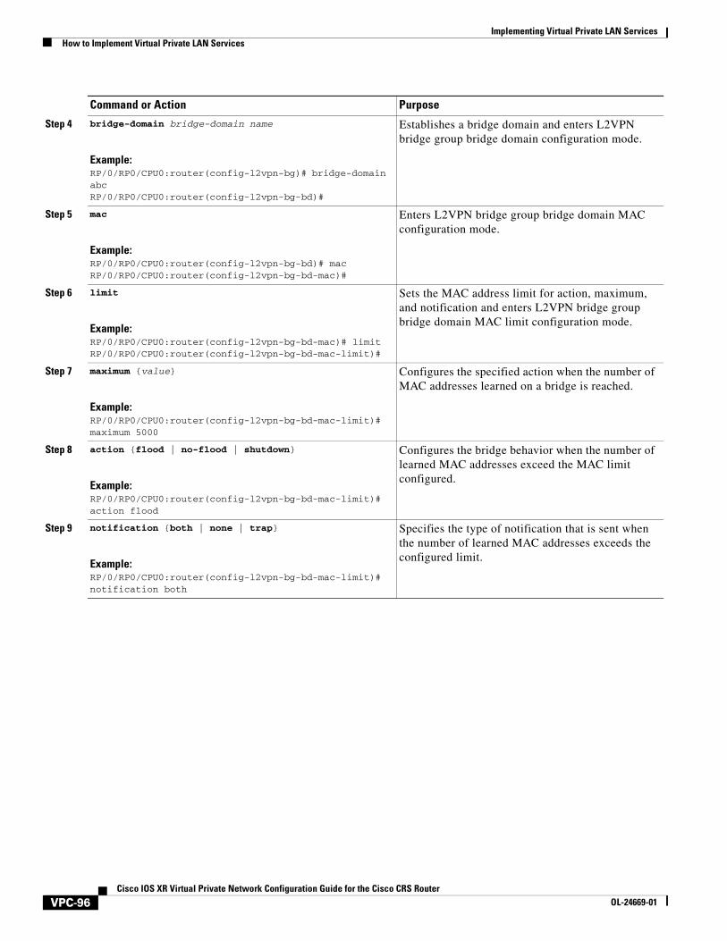
Implementing Virtual Private LAN Services How to Implement Virtual Private LAN Services
Step 4 bridge-domain bridge-domain name
Example:RP/0/RP0/CPU0:router(config-l2vpn-bg)# bridge-domain abcRP/0/RP0/CPU0:router(config-l2vpn-bg-bd)#
Establishes a bridge domain and enters L2VPN bridge group bridge domain configuration mode.
Step 5 mac
Example:RP/0/RP0/CPU0:router(config-l2vpn-bg-bd)# macRP/0/RP0/CPU0:router(config-l2vpn-bg-bd-mac)#
Enters L2VPN bridge group bridge domain MAC configuration mode.
Step 6 limit
Example:RP/0/RP0/CPU0:router(config-l2vpn-bg-bd-mac)# limitRP/0/RP0/CPU0:router(config-l2vpn-bg-bd-mac-limit)#
Sets the MAC address limit for action, maximum, and notification and enters L2VPN bridge group bridge domain MAC limit configuration mode.
Step 7 maximum {value}
Example:RP/0/RP0/CPU0:router(config-l2vpn-bg-bd-mac-limit)# maximum 5000
Configures the specified action when the number of MAC addresses learned on a bridge is reached.
Step 8 action {flood | no-flood | shutdown}
Example:RP/0/RP0/CPU0:router(config-l2vpn-bg-bd-mac-limit)# action flood
Configures the bridge behavior when the number of learned MAC addresses exceed the MAC limit configured.
Step 9 notification {both | none | trap}
Example:RP/0/RP0/CPU0:router(config-l2vpn-bg-bd-mac-limit)# notification both
Specifies the type of notification that is sent when the number of learned MAC addresses exceeds the configured limit.
Command or Action Purpose
VPC-96Cisco IOS XR Virtual Private Network Configuration Guide for the Cisco CRS Router
OL-24669-01
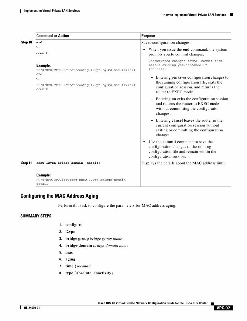
Implementing Virtual Private LAN ServicesHow to Implement Virtual Private LAN Services
Configuring the MAC Address Aging
Perform this task to configure the parameters for MAC address aging.
SUMMARY STEPS
1. configure
2. l2vpn
3. bridge group bridge group name
4. bridge-domain bridge-domain name
5. mac
6. aging
7. time {seconds}
8. type {absolute | inactivity}
Step 10 end
or
commit
Example:RP/0/RP0/CPU0:router(config-l2vpn-bg-bd-mac-limit)# end
or
RP/0/RP0/CPU0:router(config-l2vpn-bg-bd-mac-limit)# commit
Saves configuration changes.
• When you issue the end command, the system prompts you to commit changes:
Uncommitted changes found, commit them before exiting(yes/no/cancel)?[cancel]:
– Entering yes saves configuration changes to the running configuration file, exits the configuration session, and returns the router to EXEC mode.
– Entering no exits the configuration session and returns the router to EXEC mode without committing the configuration changes.
– Entering cancel leaves the router in the current configuration session without exiting or committing the configuration changes.
• Use the commit command to save the configuration changes to the running configuration file and remain within the configuration session.
Step 11 show l2vpn bridge-domain [detail]
Example:RP/0/RP0/CPU0:router# show l2vpn bridge-domain detail
Displays the details about the MAC address limit.
Command or Action Purpose
VPC-97Cisco IOS XR Virtual Private Network Configuration Guide for the Cisco CRS Router
OL-24669-01
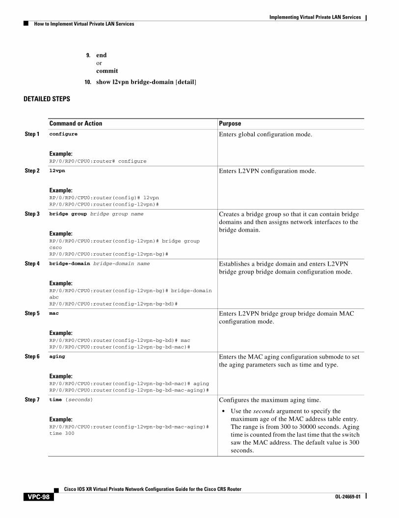
Implementing Virtual Private LAN Services How to Implement Virtual Private LAN Services
9. endorcommit
10. show l2vpn bridge-domain [detail]
DETAILED STEPS
Command or Action Purpose
Step 1 configure
Example:RP/0/RP0/CPU0:router# configure
Enters global configuration mode.
Step 2 l2vpn
Example:RP/0/RP0/CPU0:router(config)# l2vpnRP/0/RP0/CPU0:router(config-l2vpn)#
Enters L2VPN configuration mode.
Step 3 bridge group bridge group name
Example:RP/0/RP0/CPU0:router(config-l2vpn)# bridge group cscoRP/0/RP0/CPU0:router(config-l2vpn-bg)#
Creates a bridge group so that it can contain bridge domains and then assigns network interfaces to the bridge domain.
Step 4 bridge-domain bridge-domain name
Example:RP/0/RP0/CPU0:router(config-l2vpn-bg)# bridge-domain abcRP/0/RP0/CPU0:router(config-l2vpn-bg-bd)#
Establishes a bridge domain and enters L2VPN bridge group bridge domain configuration mode.
Step 5 mac
Example:RP/0/RP0/CPU0:router(config-l2vpn-bg-bd)# macRP/0/RP0/CPU0:router(config-l2vpn-bg-bd-mac)#
Enters L2VPN bridge group bridge domain MAC configuration mode.
Step 6 aging
Example:RP/0/RP0/CPU0:router(config-l2vpn-bg-bd-mac)# agingRP/0/RP0/CPU0:router(config-l2vpn-bg-bd-mac-aging)#
Enters the MAC aging configuration submode to set the aging parameters such as time and type.
Step 7 time {seconds}
Example:RP/0/RP0/CPU0:router(config-l2vpn-bg-bd-mac-aging)# time 300
Configures the maximum aging time.
• Use the seconds argument to specify the maximum age of the MAC address table entry. The range is from 300 to 30000 seconds. Aging time is counted from the last time that the switch saw the MAC address. The default value is 300 seconds.
VPC-98Cisco IOS XR Virtual Private Network Configuration Guide for the Cisco CRS Router
OL-24669-01
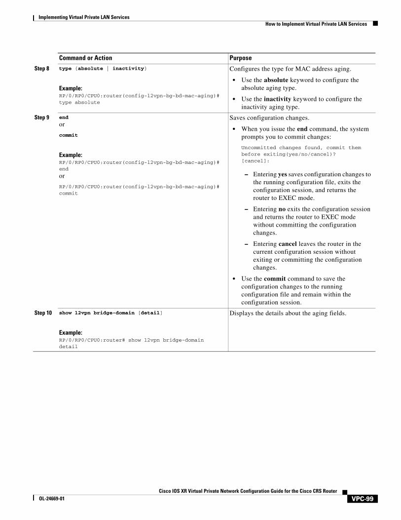
Implementing Virtual Private LAN ServicesHow to Implement Virtual Private LAN Services
Step 8 type {absolute | inactivity}
Example:RP/0/RP0/CPU0:router(config-l2vpn-bg-bd-mac-aging)# type absolute
Configures the type for MAC address aging.
• Use the absolute keyword to configure the absolute aging type.
• Use the inactivity keyword to configure the inactivity aging type.
Step 9 end
or
commit
Example:RP/0/RP0/CPU0:router(config-l2vpn-bg-bd-mac-aging)# end
or
RP/0/RP0/CPU0:router(config-l2vpn-bg-bd-mac-aging)# commit
Saves configuration changes.
• When you issue the end command, the system prompts you to commit changes:
Uncommitted changes found, commit them before exiting(yes/no/cancel)?[cancel]:
– Entering yes saves configuration changes to the running configuration file, exits the configuration session, and returns the router to EXEC mode.
– Entering no exits the configuration session and returns the router to EXEC mode without committing the configuration changes.
– Entering cancel leaves the router in the current configuration session without exiting or committing the configuration changes.
• Use the commit command to save the configuration changes to the running configuration file and remain within the configuration session.
Step 10 show l2vpn bridge-domain [detail]
Example:RP/0/RP0/CPU0:router# show l2vpn bridge-domain detail
Displays the details about the aging fields.
Command or Action Purpose
VPC-99Cisco IOS XR Virtual Private Network Configuration Guide for the Cisco CRS Router
OL-24669-01
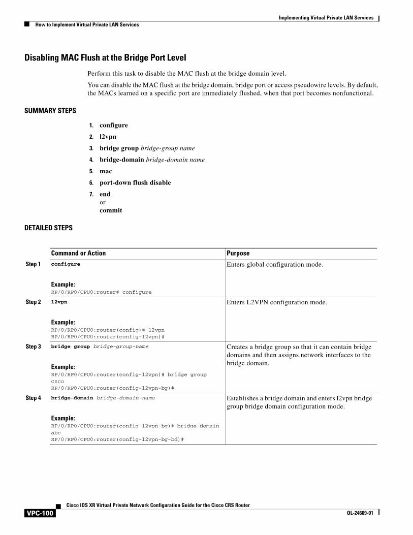
Implementing Virtual Private LAN Services How to Implement Virtual Private LAN Services
Disabling MAC Flush at the Bridge Port Level
Perform this task to disable the MAC flush at the bridge domain level.
You can disable the MAC flush at the bridge domain, bridge port or access pseudowire levels. By default, the MACs learned on a specific port are immediately flushed, when that port becomes nonfunctional.
SUMMARY STEPS
1. configure
2. l2vpn
3. bridge group bridge-group name
4. bridge-domain bridge-domain name
5. mac
6. port-down flush disable
7. endorcommit
DETAILED STEPS
Command or Action Purpose
Step 1 configure
Example:RP/0/RP0/CPU0:router# configure
Enters global configuration mode.
Step 2 l2vpn
Example:RP/0/RP0/CPU0:router(config)# l2vpnRP/0/RP0/CPU0:router(config-l2vpn)#
Enters L2VPN configuration mode.
Step 3 bridge group bridge-group-name
Example:RP/0/RP0/CPU0:router(config-l2vpn)# bridge group cscoRP/0/RP0/CPU0:router(config-l2vpn-bg)#
Creates a bridge group so that it can contain bridge domains and then assigns network interfaces to the bridge domain.
Step 4 bridge-domain bridge-domain-name
Example:RP/0/RP0/CPU0:router(config-l2vpn-bg)# bridge-domain abcRP/0/RP0/CPU0:router(config-l2vpn-bg-bd)#
Establishes a bridge domain and enters l2vpn bridge group bridge domain configuration mode.
VPC-100Cisco IOS XR Virtual Private Network Configuration Guide for the Cisco CRS Router
OL-24669-01
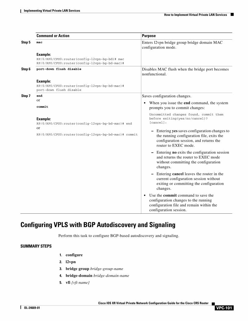
Implementing Virtual Private LAN ServicesHow to Implement Virtual Private LAN Services
Configuring VPLS with BGP Autodiscovery and SignalingPerform this task to configure BGP-based autodiscovery and signaling.
SUMMARY STEPS
1. configure
2. l2vpn
3. bridge group bridge-group-name
4. bridge-domain bridge-domain-name
5. vfi {vfi-name}
Step 5 mac
Example:RP/0/RP0/CPU0:router(config-l2vpn-bg-bd)# macRP/0/RP0/CPU0:router(config-l2vpn-bg-bd-mac)#
Enters l2vpn bridge group bridge domain MAC configuration mode.
Step 6 port-down flush disable
Example:RP/0/RP0/CPU0:router(config-l2vpn-bg-bd-mac)#port-down flush disable
Disables MAC flush when the bridge port becomes nonfunctional.
Step 7 end
or
commit
Example:RP/0/RP0/CPU0:router(config-l2vpn-bg-bd-mac)# end
or
RP/0/RP0/CPU0:router(config-l2vpn-bg-bd-mac)# commit
Saves configuration changes.
• When you issue the end command, the system prompts you to commit changes:
Uncommitted changes found, commit them before exiting(yes/no/cancel)?[cancel]:
– Entering yes saves configuration changes to the running configuration file, exits the configuration session, and returns the router to EXEC mode.
– Entering no exits the configuration session and returns the router to EXEC mode without committing the configuration changes.
– Entering cancel leaves the router in the current configuration session without exiting or committing the configuration changes.
• Use the commit command to save the configuration changes to the running configuration file and remain within the configuration session.
Command or Action Purpose
VPC-101Cisco IOS XR Virtual Private Network Configuration Guide for the Cisco CRS Router
OL-24669-01
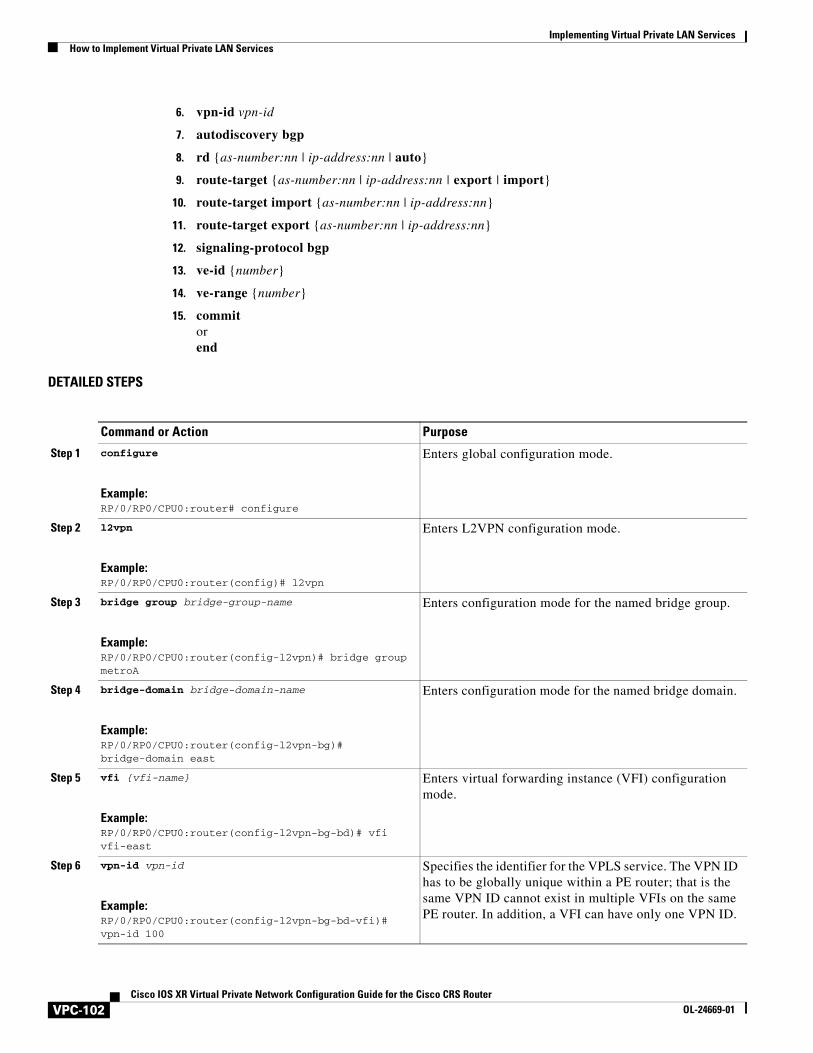
Implementing Virtual Private LAN Services How to Implement Virtual Private LAN Services
6. vpn-id vpn-id
7. autodiscovery bgp
8. rd {as-number:nn | ip-address:nn | auto}
9. route-target {as-number:nn | ip-address:nn | export | import}
10. route-target import {as-number:nn | ip-address:nn}
11. route-target export {as-number:nn | ip-address:nn}
12. signaling-protocol bgp
13. ve-id {number}
14. ve-range {number}
15. commit orend
DETAILED STEPS
Command or Action Purpose
Step 1 configure
Example:RP/0/RP0/CPU0:router# configure
Enters global configuration mode.
Step 2 l2vpn
Example:RP/0/RP0/CPU0:router(config)# l2vpn
Enters L2VPN configuration mode.
Step 3 bridge group bridge-group-name
Example:RP/0/RP0/CPU0:router(config-l2vpn)# bridge group metroA
Enters configuration mode for the named bridge group.
Step 4 bridge-domain bridge-domain-name
Example:RP/0/RP0/CPU0:router(config-l2vpn-bg)# bridge-domain east
Enters configuration mode for the named bridge domain.
Step 5 vfi {vfi-name}
Example:RP/0/RP0/CPU0:router(config-l2vpn-bg-bd)# vfi vfi-east
Enters virtual forwarding instance (VFI) configuration mode.
Step 6 vpn-id vpn-id
Example:RP/0/RP0/CPU0:router(config-l2vpn-bg-bd-vfi)# vpn-id 100
Specifies the identifier for the VPLS service. The VPN ID has to be globally unique within a PE router; that is the same VPN ID cannot exist in multiple VFIs on the same PE router. In addition, a VFI can have only one VPN ID.
VPC-102Cisco IOS XR Virtual Private Network Configuration Guide for the Cisco CRS Router
OL-24669-01
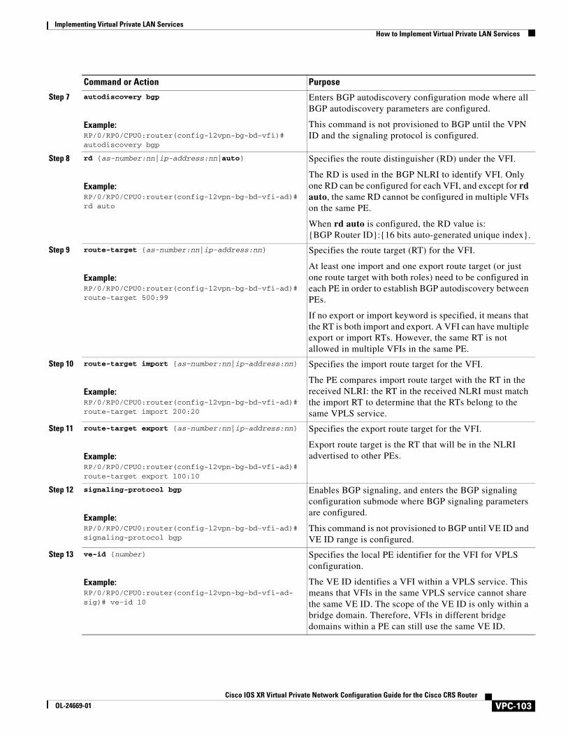
Implementing Virtual Private LAN ServicesHow to Implement Virtual Private LAN Services
Step 7 autodiscovery bgp
Example:RP/0/RP0/CPU0:router(config-l2vpn-bg-bd-vfi)# autodiscovery bgp
Enters BGP autodiscovery configuration mode where all BGP autodiscovery parameters are configured.
This command is not provisioned to BGP until the VPN ID and the signaling protocol is configured.
Step 8 rd {as-number:nn|ip-address:nn|auto}
Example:RP/0/RP0/CPU0:router(config-l2vpn-bg-bd-vfi-ad)# rd auto
Specifies the route distinguisher (RD) under the VFI.
The RD is used in the BGP NLRI to identify VFI. Only one RD can be configured for each VFI, and except for rd auto, the same RD cannot be configured in multiple VFIs on the same PE.
When rd auto is configured, the RD value is: {BGP Router ID}:{16 bits auto-generated unique index}.
Step 9 route-target {as-number:nn|ip-address:nn}
Example:RP/0/RP0/CPU0:router(config-l2vpn-bg-bd-vfi-ad)# route-target 500:99
Specifies the route target (RT) for the VFI.
At least one import and one export route target (or just one route target with both roles) need to be configured in each PE in order to establish BGP autodiscovery between PEs.
If no export or import keyword is specified, it means that the RT is both import and export. A VFI can have multiple export or import RTs. However, the same RT is not allowed in multiple VFIs in the same PE.
Step 10 route-target import {as-number:nn|ip-address:nn}
Example:RP/0/RP0/CPU0:router(config-l2vpn-bg-bd-vfi-ad)# route-target import 200:20
Specifies the import route target for the VFI.
The PE compares import route target with the RT in the received NLRI: the RT in the received NLRI must match the import RT to determine that the RTs belong to the same VPLS service.
Step 11 route-target export {as-number:nn|ip-address:nn}
Example:RP/0/RP0/CPU0:router(config-l2vpn-bg-bd-vfi-ad)# route-target export 100:10
Specifies the export route target for the VFI.
Export route target is the RT that will be in the NLRI advertised to other PEs.
Step 12 signaling-protocol bgp
Example:RP/0/RP0/CPU0:router(config-l2vpn-bg-bd-vfi-ad)# signaling-protocol bgp
Enables BGP signaling, and enters the BGP signaling configuration submode where BGP signaling parameters are configured.
This command is not provisioned to BGP until VE ID and VE ID range is configured.
Step 13 ve-id {number}
Example:RP/0/RP0/CPU0:router(config-l2vpn-bg-bd-vfi-ad-sig)# ve-id 10
Specifies the local PE identifier for the VFI for VPLS configuration.
The VE ID identifies a VFI within a VPLS service. This means that VFIs in the same VPLS service cannot share the same VE ID. The scope of the VE ID is only within a bridge domain. Therefore, VFIs in different bridge domains within a PE can still use the same VE ID.
Command or Action Purpose
VPC-103Cisco IOS XR Virtual Private Network Configuration Guide for the Cisco CRS Router
OL-24669-01
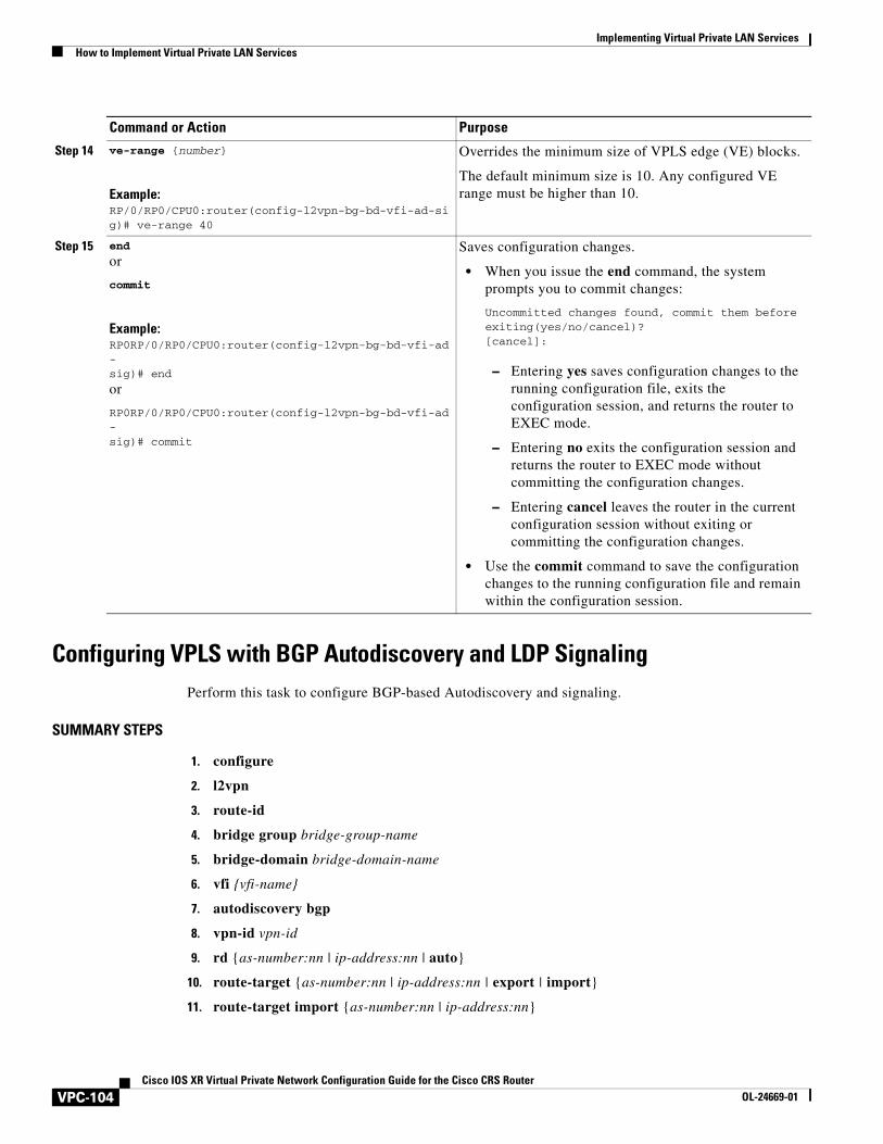
Implementing Virtual Private LAN Services How to Implement Virtual Private LAN Services
Configuring VPLS with BGP Autodiscovery and LDP SignalingPerform this task to configure BGP-based Autodiscovery and signaling.
SUMMARY STEPS
1. configure
2. l2vpn
3. route-id
4. bridge group bridge-group-name
5. bridge-domain bridge-domain-name
6. vfi {vfi-name}
7. autodiscovery bgp
8. vpn-id vpn-id
9. rd {as-number:nn | ip-address:nn | auto}
10. route-target {as-number:nn | ip-address:nn | export | import}
11. route-target import {as-number:nn | ip-address:nn}
Step 14 ve-range {number}
Example:RP/0/RP0/CPU0:router(config-l2vpn-bg-bd-vfi-ad-sig)# ve-range 40
Overrides the minimum size of VPLS edge (VE) blocks.
The default minimum size is 10. Any configured VE range must be higher than 10.
Step 15 end
or
commit
Example:RP0RP/0/RP0/CPU0:router(config-l2vpn-bg-bd-vfi-ad-sig)# end
or
RP0RP/0/RP0/CPU0:router(config-l2vpn-bg-bd-vfi-ad-sig)# commit
Saves configuration changes.
• When you issue the end command, the system prompts you to commit changes:
Uncommitted changes found, commit them before exiting(yes/no/cancel)?[cancel]:
– Entering yes saves configuration changes to the running configuration file, exits the configuration session, and returns the router to EXEC mode.
– Entering no exits the configuration session and returns the router to EXEC mode without committing the configuration changes.
– Entering cancel leaves the router in the current configuration session without exiting or committing the configuration changes.
• Use the commit command to save the configuration changes to the running configuration file and remain within the configuration session.
Command or Action Purpose
VPC-104Cisco IOS XR Virtual Private Network Configuration Guide for the Cisco CRS Router
OL-24669-01
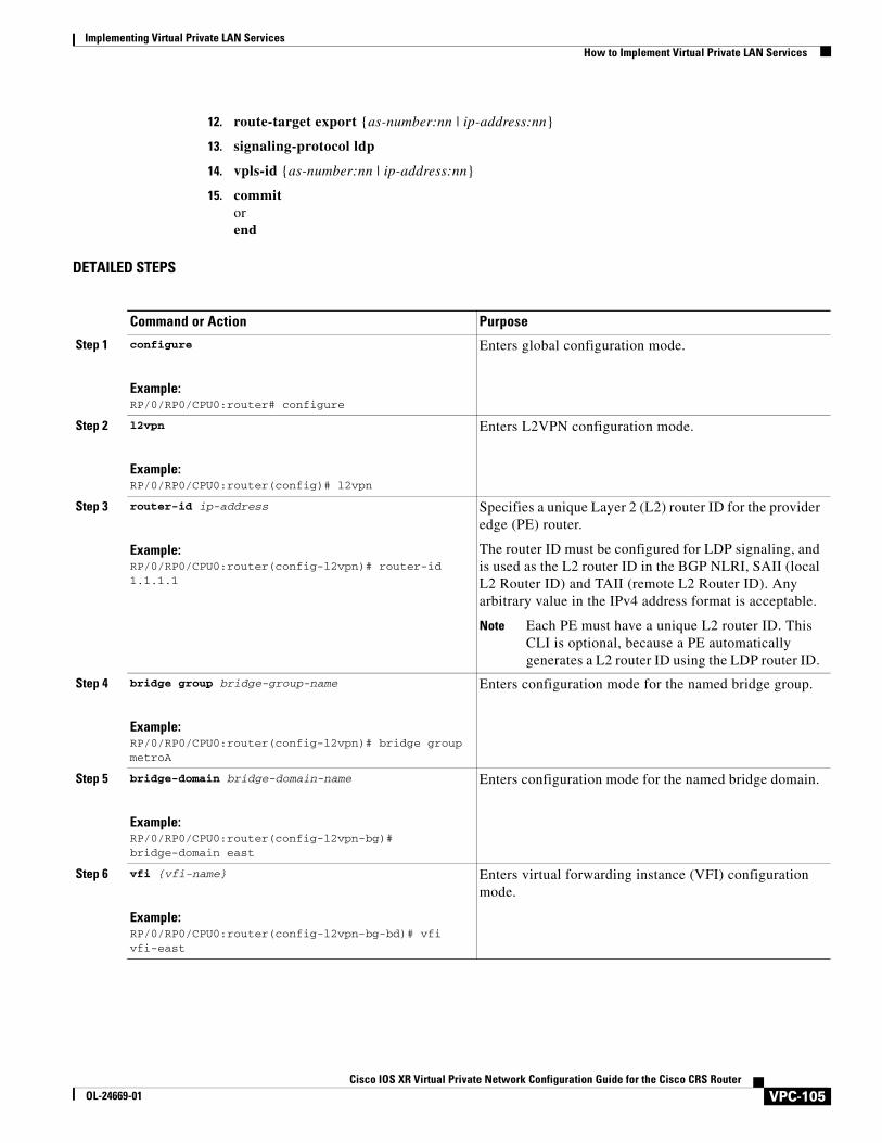
Implementing Virtual Private LAN ServicesHow to Implement Virtual Private LAN Services
12. route-target export {as-number:nn | ip-address:nn}
13. signaling-protocol ldp
14. vpls-id {as-number:nn | ip-address:nn}
15. commit orend
DETAILED STEPS
Command or Action Purpose
Step 1 configure
Example:RP/0/RP0/CPU0:router# configure
Enters global configuration mode.
Step 2 l2vpn
Example:RP/0/RP0/CPU0:router(config)# l2vpn
Enters L2VPN configuration mode.
Step 3 router-id ip-address
Example:RP/0/RP0/CPU0:router(config-l2vpn)# router-id 1.1.1.1
Specifies a unique Layer 2 (L2) router ID for the provider edge (PE) router.
The router ID must be configured for LDP signaling, and is used as the L2 router ID in the BGP NLRI, SAII (local L2 Router ID) and TAII (remote L2 Router ID). Any arbitrary value in the IPv4 address format is acceptable.
Note Each PE must have a unique L2 router ID. This CLI is optional, because a PE automatically generates a L2 router ID using the LDP router ID.
Step 4 bridge group bridge-group-name
Example:RP/0/RP0/CPU0:router(config-l2vpn)# bridge group metroA
Enters configuration mode for the named bridge group.
Step 5 bridge-domain bridge-domain-name
Example:RP/0/RP0/CPU0:router(config-l2vpn-bg)# bridge-domain east
Enters configuration mode for the named bridge domain.
Step 6 vfi {vfi-name}
Example:RP/0/RP0/CPU0:router(config-l2vpn-bg-bd)# vfi vfi-east
Enters virtual forwarding instance (VFI) configuration mode.
VPC-105Cisco IOS XR Virtual Private Network Configuration Guide for the Cisco CRS Router
OL-24669-01
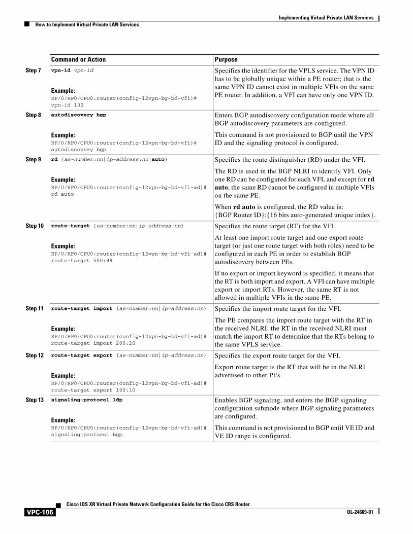
Implementing Virtual Private LAN Services How to Implement Virtual Private LAN Services
Step 7 vpn-id vpn-id
Example:RP/0/RP0/CPU0:router(config-l2vpn-bg-bd-vfi)# vpn-id 100
Specifies the identifier for the VPLS service. The VPN ID has to be globally unique within a PE router; that is the same VPN ID cannot exist in multiple VFIs on the same PE router. In addition, a VFI can have only one VPN ID.
Step 8 autodiscovery bgp
Example:RP/0/RP0/CPU0:router(config-l2vpn-bg-bd-vfi)# autodiscovery bgp
Enters BGP autodiscovery configuration mode where all BGP autodiscovery parameters are configured.
This command is not provisioned to BGP until the VPN ID and the signaling protocol is configured.
Step 9 rd {as-number:nn|ip-address:nn|auto}
Example:RP/0/RP0/CPU0:router(config-l2vpn-bg-bd-vfi-ad)# rd auto
Specifies the route distinguisher (RD) under the VFI.
The RD is used in the BGP NLRI to identify VFI. Only one RD can be configured for each VFI, and except for rd auto, the same RD cannot be configured in multiple VFIs on the same PE.
When rd auto is configured, the RD value is: {BGP Router ID}:{16 bits auto-generated unique index}.
Step 10 route-target {as-number:nn|ip-address:nn}
Example:RP/0/RP0/CPU0:router(config-l2vpn-bg-bd-vfi-ad)# route-target 500:99
Specifies the route target (RT) for the VFI.
At least one import route target and one export route target (or just one route target with both roles) need to be configured in each PE in order to establish BGP autodiscovery between PEs.
If no export or import keyword is specified, it means that the RT is both import and export. A VFI can have multiple export or import RTs. However, the same RT is not allowed in multiple VFIs in the same PE.
Step 11 route-target import {as-number:nn|ip-address:nn}
Example:RP/0/RP0/CPU0:router(config-l2vpn-bg-bd-vfi-ad)# route-target import 200:20
Specifies the import route target for the VFI.
The PE compares the import route target with the RT in the received NLRI: the RT in the received NLRI must match the import RT to determine that the RTs belong to the same VPLS service.
Step 12 route-target export {as-number:nn|ip-address:nn}
Example:RP/0/RP0/CPU0:router(config-l2vpn-bg-bd-vfi-ad)# route-target export 100:10
Specifies the export route target for the VFI.
Export route target is the RT that will be in the NLRI advertised to other PEs.
Step 13 signaling-protocol ldp
Example:RP/0/RP0/CPU0:router(config-l2vpn-bg-bd-vfi-ad)# signaling-protocol bgp
Enables BGP signaling, and enters the BGP signaling configuration submode where BGP signaling parameters are configured.
This command is not provisioned to BGP until VE ID and VE ID range is configured.
Command or Action Purpose
VPC-106Cisco IOS XR Virtual Private Network Configuration Guide for the Cisco CRS Router
OL-24669-01
Implementing Virtual Private LAN ServicesHow to Implement Virtual Private LAN Services
Configuring Pseudowire HeadendThe PWHE is created by configuring interface pw-ether or pw-iw. For the PWHE to be functional, the xconnect has to be configured completely. Configuring other layer 3 (L3) parameters, such as VRF and IP addresses, are optional for the PWHE to be functional. However, the L3 features are required for the layer 3 services to be operational; that is, for PW L3 termination.
This section describes these topics:
• PWHE Configuration Restrictions
• Configuring PWHE Interfaces
• Configuring PWHE Interface Parameters
• Configuring PWHE Crossconnect
Step 14 vpls-id {as-number:nn|ip-address:nn}
Example:RP/0/RP0/CPU0:router(config-l2vpn-bg-bd-vfi-ad-sig)# vpls-id 10:20
Specifies VPLS ID which identifies the VPLS domain during signaling.
This command is optional in all PEs that are in the same Autonomous System (that is, PEs that share the same ASN) because a default VPLS ID is automatically generated using BGP's ASN and the configured VPN ID (that is, the default VPLS ID equals ASN:VPN-ID). If an ASN of 4 bytes is used, the lower two bytes of the ASN are used to build the VPLS ID. In case of InterAS, the VPLS ID must be explicitly configured. Only one VPLS ID can be configured for each VFI, and the same VPLS ID cannot be used for multiple VFIs.
Step 15 end
or
commit
Example:RP0RP/0/RP0/CPU0:router(config-l2vpn-bg-bd-vfi-ad-sig)# end
or
RP0RP/0/RP0/CPU0:router(config-l2vpn-bg-bd-vfi-ad-sig)# commit
Saves configuration changes.
• When you issue the end command, the system prompts you to commit changes:
Uncommitted changes found, commit them before exiting(yes/no/cancel)?[cancel]:
– Entering yes saves configuration changes to the running configuration file, exits the configuration session, and returns the router to EXEC mode.
– Entering no exits the configuration session and returns the router to EXEC mode without committing the configuration changes.
– Entering cancel leaves the router in the current configuration session without exiting or committing the configuration changes.
• Use the commit command to save the configuration changes to the running configuration file and remain within the configuration session.
Command or Action Purpose
VPC-107Cisco IOS XR Virtual Private Network Configuration Guide for the Cisco CRS Router
OL-24669-01
Implementing Virtual Private LAN Services How to Implement Virtual Private LAN Services
PWHE Configuration Restrictions
These are the configuration restrictions for PWHE:
• Up to 4096 PWHE interfaces (a combination of pw-ether and pw-iw).
• Up to eight interface lists per peer.
• Up to eight L3 links per interface list.
• VLAN ID (tag-impose) can be configured only in xconnects which have pw-ether interfaces.
• VLAN ID (tag-impose) can only be configured under VC type 4 pw-ether interfaces.
• Interface lists can be configured on CRS only.
• Interface lists can accept POS, GigabitEthernet, TenGigabitEthernet, SRP, Bundle Ethernet and Bundle POS; other interfaces are rejected.
• No support for features such as pseudowire redundancy, preferred path, local switching or L2TP for xconnects configured with PWHE.
• Ethernet and VLAN transport modes are not allowed for pw-iw xconnects.
• Address family, Cisco Discovery Protocol (CDP) and MPLS configurations are not allowed on PWHE interfaces.
• IPv6 configuration is not allowed under pw-iw interfaces.
Configuring PWHE Interfaces
Perform this task to configure PWHE interfaces.
Summary Steps
1. configure
2. interface pw-ether id
3. attach generic-interface-list interface_list_name
4. endorcommit
VPC-108Cisco IOS XR Virtual Private Network Configuration Guide for the Cisco CRS Router
OL-24669-01
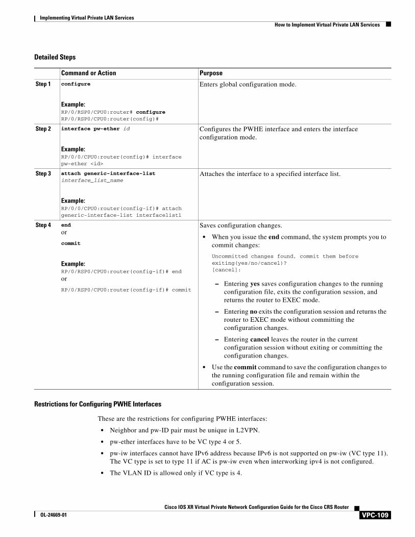
Implementing Virtual Private LAN ServicesHow to Implement Virtual Private LAN Services
Detailed Steps
Restrictions for Configuring PWHE Interfaces
These are the restrictions for configuring PWHE interfaces:
• Neighbor and pw-ID pair must be unique in L2VPN.
• pw-ether interfaces have to be VC type 4 or 5.
• pw-iw interfaces cannot have IPv6 address because IPv6 is not supported on pw-iw (VC type 11). The VC type is set to type 11 if AC is pw-iw even when interworking ipv4 is not configured.
• The VLAN ID is allowed only if VC type is 4.
Command or Action Purpose
Step 1 configure
Example:RP/0/RSP0/CPU0:router# configureRP/0/RSP0/CPU0:router(config)#
Enters global configuration mode.
Step 2 interface pw-ether id
Example:RP/0/0/CPU0:router(config)# interface pw-ether <id>
Configures the PWHE interface and enters the interface configuration mode.
Step 3 attach generic-interface-list interface_list_name
Example:RP/0/0/CPU0:router(config-if)# attach generic-interface-list interfacelist1
Attaches the interface to a specified interface list.
Step 4 end
or
commit
Example:RP/0/RSP0/CPU0:router(config-if)# end
or
RP/0/RSP0/CPU0:router(config-if)# commit
Saves configuration changes.
• When you issue the end command, the system prompts you to commit changes:
Uncommitted changes found, commit them before exiting(yes/no/cancel)?[cancel]:
– Entering yes saves configuration changes to the running configuration file, exits the configuration session, and returns the router to EXEC mode.
– Entering no exits the configuration session and returns the router to EXEC mode without committing the configuration changes.
– Entering cancel leaves the router in the current configuration session without exiting or committing the configuration changes.
• Use the commit command to save the configuration changes to the running configuration file and remain within the configuration session.
VPC-109Cisco IOS XR Virtual Private Network Configuration Guide for the Cisco CRS Router
OL-24669-01
Implementing Virtual Private LAN Services How to Implement Virtual Private LAN Services
• MPLS protocols (MPLS-TE, LDP, RSVP) cannot be configured on PW-HE.
• No interface list configuration is accepted on non-PWHE platforms.
Configuring PWHE Interface Parameters
Perform this task to configure PWHE interface parameters.
Summary Steps
1. configure
2. interface pw-ether id
3. attach generic-interface-list interface_list_name
4. l2overhead bytes
5. load-interval seconds
6. dampening decay-life
7. logging events link-status
8. mac-address MAC address
9. mtu interface_MTU
10. endorcommit
VPC-110Cisco IOS XR Virtual Private Network Configuration Guide for the Cisco CRS Router
OL-24669-01
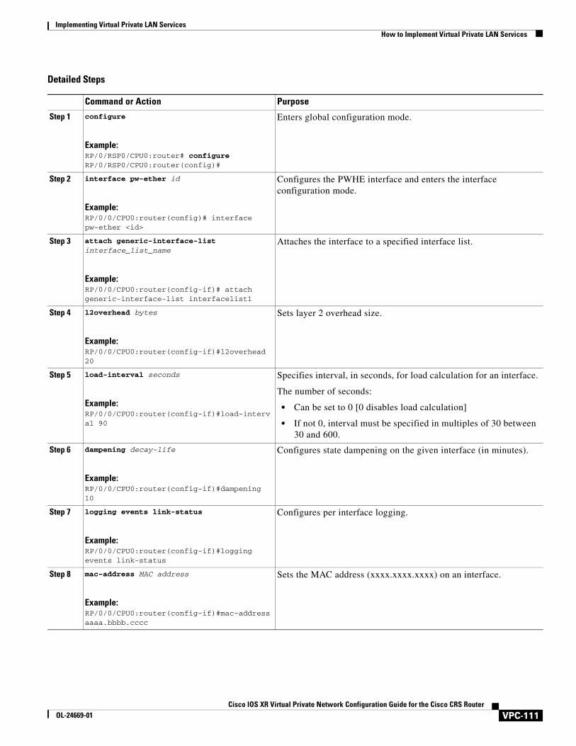
Implementing Virtual Private LAN ServicesHow to Implement Virtual Private LAN Services
Detailed Steps
Command or Action Purpose
Step 1 configure
Example:RP/0/RSP0/CPU0:router# configureRP/0/RSP0/CPU0:router(config)#
Enters global configuration mode.
Step 2 interface pw-ether id
Example:RP/0/0/CPU0:router(config)# interface pw-ether <id>
Configures the PWHE interface and enters the interface configuration mode.
Step 3 attach generic-interface-list interface_list_name
Example:RP/0/0/CPU0:router(config-if)# attach generic-interface-list interfacelist1
Attaches the interface to a specified interface list.
Step 4 l2overhead bytes
Example:RP/0/0/CPU0:router(config-if)#l2overhead 20
Sets layer 2 overhead size.
Step 5 load-interval seconds
Example:RP/0/0/CPU0:router(config-if)#load-interval 90
Specifies interval, in seconds, for load calculation for an interface.
The number of seconds:
• Can be set to 0 [0 disables load calculation]
• If not 0, interval must be specified in multiples of 30 between 30 and 600.
Step 6 dampening decay-life
Example:RP/0/0/CPU0:router(config-if)#dampening 10
Configures state dampening on the given interface (in minutes).
Step 7 logging events link-status
Example:RP/0/0/CPU0:router(config-if)#logging events link-status
Configures per interface logging.
Step 8 mac-address MAC address
Example:RP/0/0/CPU0:router(config-if)#mac-address aaaa.bbbb.cccc
Sets the MAC address (xxxx.xxxx.xxxx) on an interface.
VPC-111Cisco IOS XR Virtual Private Network Configuration Guide for the Cisco CRS Router
OL-24669-01
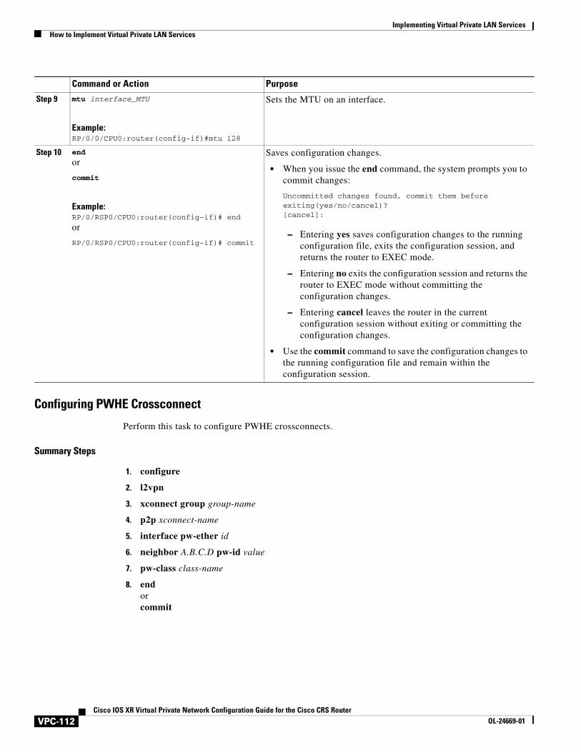
Implementing Virtual Private LAN Services How to Implement Virtual Private LAN Services
Configuring PWHE Crossconnect
Perform this task to configure PWHE crossconnects.
Summary Steps
1. configure
2. l2vpn
3. xconnect group group-name
4. p2p xconnect-name
5. interface pw-ether id
6. neighbor A.B.C.D pw-id value
7. pw-class class-name
8. endorcommit
Step 9 mtu interface_MTU
Example:RP/0/0/CPU0:router(config-if)#mtu 128
Sets the MTU on an interface.
Step 10 end
or
commit
Example:RP/0/RSP0/CPU0:router(config-if)# end
or
RP/0/RSP0/CPU0:router(config-if)# commit
Saves configuration changes.
• When you issue the end command, the system prompts you to commit changes:
Uncommitted changes found, commit them before exiting(yes/no/cancel)?[cancel]:
– Entering yes saves configuration changes to the running configuration file, exits the configuration session, and returns the router to EXEC mode.
– Entering no exits the configuration session and returns the router to EXEC mode without committing the configuration changes.
– Entering cancel leaves the router in the current configuration session without exiting or committing the configuration changes.
• Use the commit command to save the configuration changes to the running configuration file and remain within the configuration session.
Command or Action Purpose
VPC-112Cisco IOS XR Virtual Private Network Configuration Guide for the Cisco CRS Router
OL-24669-01
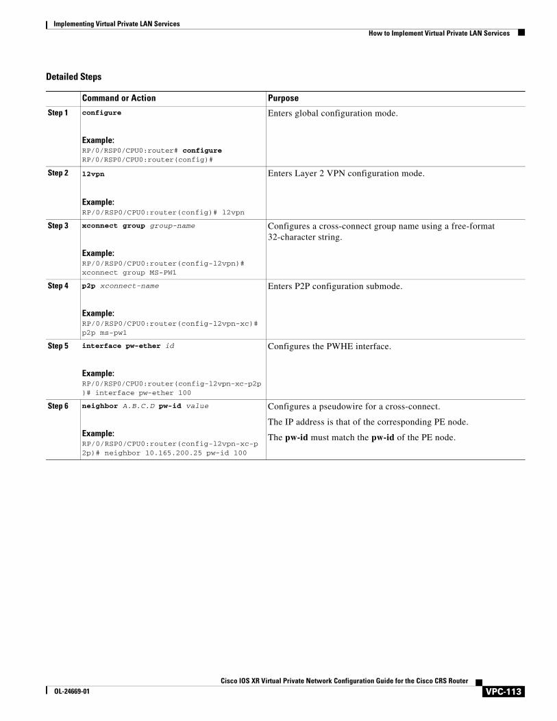
Implementing Virtual Private LAN ServicesHow to Implement Virtual Private LAN Services
Detailed Steps
Command or Action Purpose
Step 1 configure
Example:RP/0/RSP0/CPU0:router# configureRP/0/RSP0/CPU0:router(config)#
Enters global configuration mode.
Step 2 l2vpn
Example:RP/0/RSP0/CPU0:router(config)# l2vpn
Enters Layer 2 VPN configuration mode.
Step 3 xconnect group group-name
Example:RP/0/RSP0/CPU0:router(config-l2vpn)# xconnect group MS-PW1
Configures a cross-connect group name using a free-format 32-character string.
Step 4 p2p xconnect-name
Example:RP/0/RSP0/CPU0:router(config-l2vpn-xc)# p2p ms-pw1
Enters P2P configuration submode.
Step 5 interface pw-ether id
Example:RP/0/RSP0/CPU0:router(config-l2vpn-xc-p2p)# interface pw-ether 100
Configures the PWHE interface.
Step 6 neighbor A.B.C.D pw-id value
Example:RP/0/RSP0/CPU0:router(config-l2vpn-xc-p2p)# neighbor 10.165.200.25 pw-id 100
Configures a pseudowire for a cross-connect.
The IP address is that of the corresponding PE node.
The pw-id must match the pw-id of the PE node.
VPC-113Cisco IOS XR Virtual Private Network Configuration Guide for the Cisco CRS Router
OL-24669-01
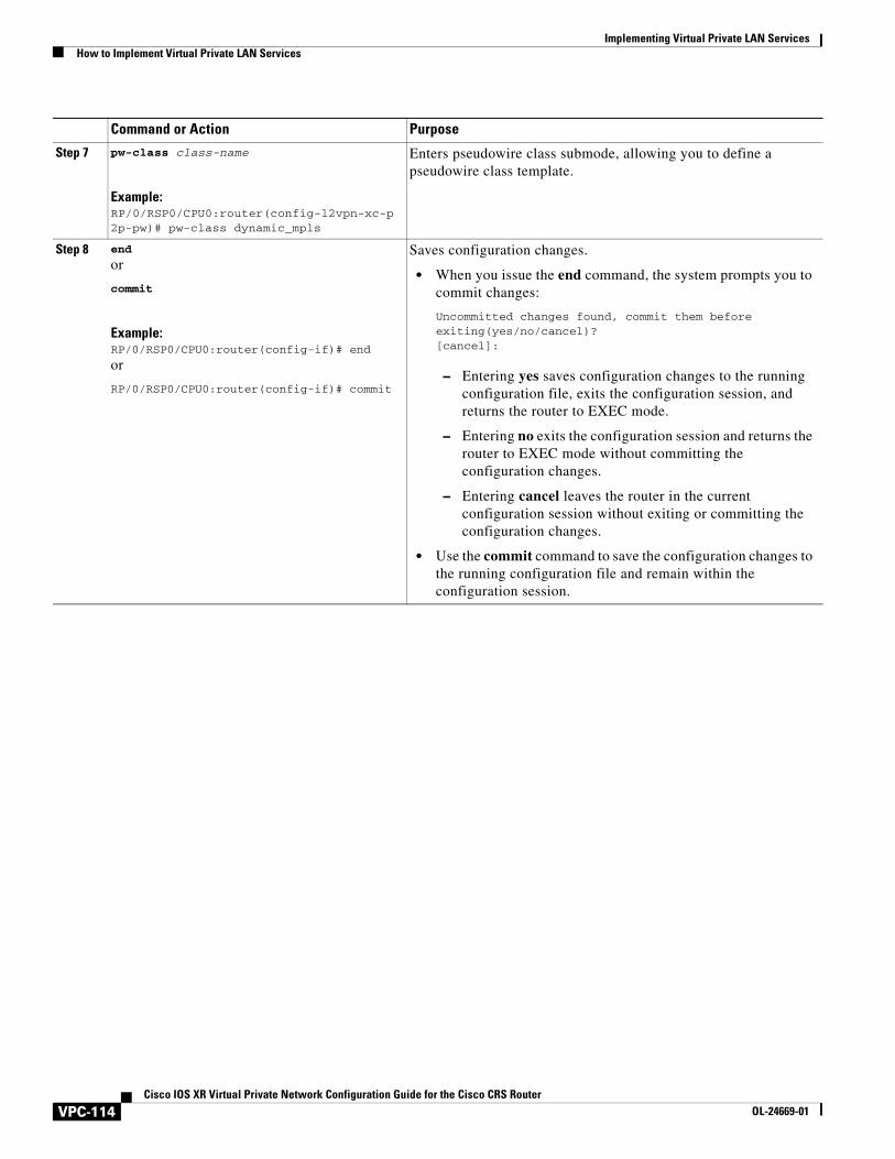
Implementing Virtual Private LAN Services How to Implement Virtual Private LAN Services
Step 7 pw-class class-name
Example:RP/0/RSP0/CPU0:router(config-l2vpn-xc-p2p-pw)# pw-class dynamic_mpls
Enters pseudowire class submode, allowing you to define a pseudowire class template.
Step 8 end
or
commit
Example:RP/0/RSP0/CPU0:router(config-if)# end
or
RP/0/RSP0/CPU0:router(config-if)# commit
Saves configuration changes.
• When you issue the end command, the system prompts you to commit changes:
Uncommitted changes found, commit them before exiting(yes/no/cancel)?[cancel]:
– Entering yes saves configuration changes to the running configuration file, exits the configuration session, and returns the router to EXEC mode.
– Entering no exits the configuration session and returns the router to EXEC mode without committing the configuration changes.
– Entering cancel leaves the router in the current configuration session without exiting or committing the configuration changes.
• Use the commit command to save the configuration changes to the running configuration file and remain within the configuration session.
Command or Action Purpose
VPC-114Cisco IOS XR Virtual Private Network Configuration Guide for the Cisco CRS Router
OL-24669-01
Implementing Virtual Private LAN ServicesConfiguration Examples for Virtual Private LAN Services
Configuration Examples for Virtual Private LAN ServicesThis section includes the following configuration examples:
• Virtual Private LAN Services Configuration for Provider Edge-to-Provider Edge: Example, page VPC-115
• Virtual Private LAN Services Configuration for Provider Edge-to-Customer Edge: Example, page VPC-116
• Configuring Backup Disable Delay: Example, page VPC-117
• Disabling MAC Flush: Examples, page VPC-117
• H-VPLS Configuration: Examples, page VPC-118
• Configuring VPLS with BGP Autodiscovery and Signaling: Example, page VPC-120
• Configuring Pseudowire Headend: Example, page VPC-125
Virtual Private LAN Services Configuration for Provider Edge-to-Provider Edge: Example
These configuration examples show how to create a Layer 2 VFI with a full-mesh of participating VPLS provider edge (PE) nodes.
The following configuration example shows how to configure PE 1:
configure l2vpn bridge group 1 bridge-domain PE1-VPLS-A GigabitEthernet0/0---AC exit vfi 1 neighbor 2.2.2.2 pw-id 1---PW1 neighbor 3.3.3.3 pw-id 1---PW2 ! ! interface loopback 0 ipv4 address 1.1.1.1 255.255.255.25 commit
The following configuration example shows how to configure PE 2:
configure l2vpn bridge group 1 bridge-domain PE2-VPLS-A interface GigabitEthernet0/0---AC exit vfi 1 neighbor 1.1.1.1 pw-id 1---PW1 neighbor 3.3.3.3 pw-id 1---PW2 ! ! interface loopback 0 ipv4 address 2.2.2.2 255.255.255.25 commit
The following configuration example shows how to configure PE 3:
VPC-115Cisco IOS XR Virtual Private Network Configuration Guide for the Cisco CRS Router
OL-24669-01
Implementing Virtual Private LAN Services Configuration Examples for Virtual Private LAN Services
configure l2vpn bridge group 1 bridge-domain PE3-VPLS-A interface GigabitEthernet0/0---AC exit vfi 1 neighbor 1.1.1.1 pw-id 1---PW1 neighbor 2.2.2.2 pw-id 1---PW2 ! ! interface loopback 0 ipv4 address 3.3.3.3 255.255.255.25 commit
Virtual Private LAN Services Configuration for Provider Edge-to-Customer Edge: Example
The following configuration shows how to configure VPLS for a PE-to-CE nodes:
configure interface GigabitEthernet0/0 l2transport---AC interface exit no ipv4 address no ipv4 directed-broadcast negotiation auto no cdp enable end configure interface GigabitEthernet0/0 l2transport exit no ipv4 address no ipv4 directed-broadcast negotiation auto no cdp enable end configure interface GigabitEthernet0/0 l2transport exit no ipv4 address no ipv4 directed-broadcast negotiation auto no cdp enable
VPC-116Cisco IOS XR Virtual Private Network Configuration Guide for the Cisco CRS Router
OL-24669-01
Implementing Virtual Private LAN ServicesConfiguration Examples for Virtual Private LAN Services
Configuring Backup Disable Delay: ExampleThe following example shows how a backup delay is configured for point-to-point PW where the backup disable delay is 50 seconds:
l2vpnpw-class class_1backup disable delay 20exit xconnect group_A p2p rtrX_to_rtrY neighbor 1.1.1.1 pw-id 2 pw-class class_1 backup neighbor 2.2.2.2 pw- id 5 commit
The following example shows how a backup delay is configured for point-to-point PW where the backup disable delay is never:
l2vpnpw-class class_1 backup disable never exit xconnect group_A p2p rtrX_to_rtrY neighbor 1.1.1.1 pw-id 2 pw-class class_1 backup neighbor 2.2.2.2 pw-id 5 commit
Disabling MAC Flush: ExamplesYou can disable the MAC flush at the following levels:
• bridge domain
• bridge port (attachment circuit (AC))
• access pseudowire (PW)
The following example shows how to disable the MAC flush at the bridge domain level:
configure l2vpn bridge-group group1 bridge-domain domain1 mac port-down flush disable end
The following example shows how to disable the MAC flush at the bridge port level:
configure l2vpn bridge-group group1 bridge-domain domain1 interface POS 0/1/0/1 mac port-down flush disable end
VPC-117Cisco IOS XR Virtual Private Network Configuration Guide for the Cisco CRS Router
OL-24669-01
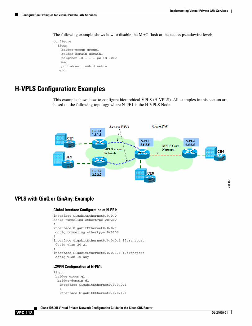
Implementing Virtual Private LAN Services Configuration Examples for Virtual Private LAN Services
The following example shows how to disable the MAC flush at the access pseudowire level:
configure l2vpn bridge-group group1 bridge-domain domain1 neighbor 10.1.1.1 pw-id 1000 mac port-down flush disable end
H-VPLS Configuration: ExamplesThis example shows how to configure hierarchical VPLS (H-VPLS). All examples in this section are based on the following topology where N-PE1 is the H-VPLS Node:
VPLS with QinQ or QinAny: Example
Global Interface Configuration at N-PE1:interface GigabitEthernet0/0/0/0dot1q tunneling ethertype 0x9200!interface GigabitEthernet0/0/0/1 dot1q tunneling ethertype 0x9100!interface GigabitEthernet0/0/0/0.1 l2transport dot1q vlan 20 21!interface GigabitEthernet0/0/0/1.1 l2transport dot1q vlan 10 any
L2VPN Configuration at N-PE1:l2vpn bridge group g1 bridge-domain d1 interface GigabitEthernet0/0/0/0.1 ! interface GigabitEthernet0/0/0/1.1
VPC-118Cisco IOS XR Virtual Private Network Configuration Guide for the Cisco CRS Router
OL-24669-01
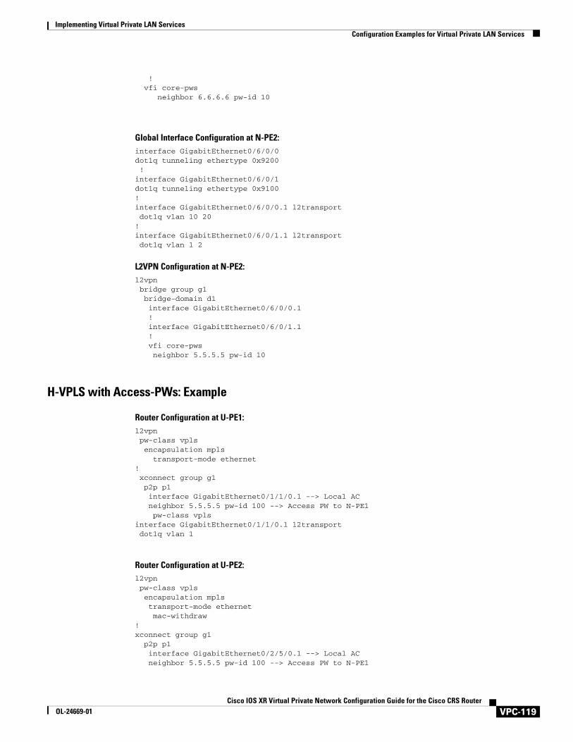
Implementing Virtual Private LAN ServicesConfiguration Examples for Virtual Private LAN Services
! vfi core-pws neighbor 6.6.6.6 pw-id 10
Global Interface Configuration at N-PE2:interface GigabitEthernet0/6/0/0dot1q tunneling ethertype 0x9200 !interface GigabitEthernet0/6/0/1dot1q tunneling ethertype 0x9100!interface GigabitEthernet0/6/0/0.1 l2transport dot1q vlan 10 20!interface GigabitEthernet0/6/0/1.1 l2transport dot1q vlan 1 2
L2VPN Configuration at N-PE2:l2vpn bridge group g1 bridge-domain d1 interface GigabitEthernet0/6/0/0.1 ! interface GigabitEthernet0/6/0/1.1 ! vfi core-pws neighbor 5.5.5.5 pw-id 10
H-VPLS with Access-PWs: Example
Router Configuration at U-PE1:l2vpn pw-class vpls encapsulation mpls transport-mode ethernet! xconnect group g1 p2p p1 interface GigabitEthernet0/1/1/0.1 --> Local AC neighbor 5.5.5.5 pw-id 100 --> Access PW to N-PE1 pw-class vplsinterface GigabitEthernet0/1/1/0.1 l2transport dot1q vlan 1
Router Configuration at U-PE2:l2vpn pw-class vpls encapsulation mpls transport-mode ethernet mac-withdraw!xconnect group g1 p2p p1 interface GigabitEthernet0/2/5/0.1 --> Local AC neighbor 5.5.5.5 pw-id 100 --> Access PW to N-PE1
VPC-119Cisco IOS XR Virtual Private Network Configuration Guide for the Cisco CRS Router
OL-24669-01
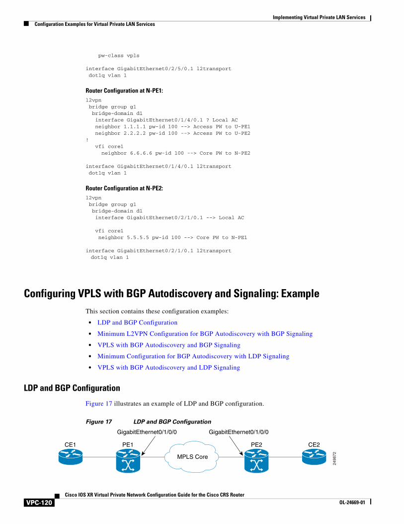
Implementing Virtual Private LAN Services Configuration Examples for Virtual Private LAN Services
pw-class vpls
interface GigabitEthernet0/2/5/0.1 l2transport dot1q vlan 1
Router Configuration at N-PE1:l2vpn bridge group g1 bridge-domain d1 interface GigabitEthernet0/1/4/0.1 ? Local AC neighbor 1.1.1.1 pw-id 100 --> Access PW to U-PE1 neighbor 2.2.2.2 pw-id 100 --> Access PW to U-PE2! vfi core1 neighbor 6.6.6.6 pw-id 100 --> Core PW to N-PE2
interface GigabitEthernet0/1/4/0.1 l2transport dot1q vlan 1
Router Configuration at N-PE2:l2vpn bridge group g1 bridge-domain d1 interface GigabitEthernet0/2/1/0.1 --> Local AC
vfi core1 neighbor 5.5.5.5 pw-id 100 --> Core PW to N-PE1
interface GigabitEthernet0/2/1/0.1 l2transport dot1q vlan 1
Configuring VPLS with BGP Autodiscovery and Signaling: ExampleThis section contains these configuration examples:
• LDP and BGP Configuration
• Minimum L2VPN Configuration for BGP Autodiscovery with BGP Signaling
• VPLS with BGP Autodiscovery and BGP Signaling
• Minimum Configuration for BGP Autodiscovery with LDP Signaling
• VPLS with BGP Autodiscovery and LDP Signaling
LDP and BGP Configuration
Figure 17 illustrates an example of LDP and BGP configuration.
Figure 17 LDP and BGP Configuration
2498
72MPLS Core
CE1 PE1 PE2 CE2
GigabitEthernet0/1/0/0 GigabitEthernet0/1/0/0
VPC-120Cisco IOS XR Virtual Private Network Configuration Guide for the Cisco CRS Router
OL-24669-01
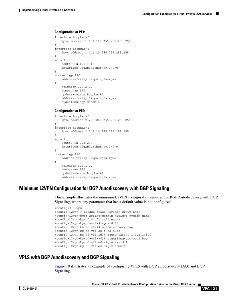
Implementing Virtual Private LAN ServicesConfiguration Examples for Virtual Private LAN Services
Configuration at PE1:interface Loopback0
ipv4 address 1.1.1.100 255.255.255.255!interface Loopback1
ipv4 address 1.1.1.10 255.255.255.255!mpls ldp
router-id 1.1.1.1interface GigabitEthernt0/1/0/0
!router bgp 120
address-family l2vpn vpls-vpws!
neighbor 2.2.2.20remote-as 120update-source Loopback1address-family l2vpn vpls-vpwssignaling bgp disable
Configuration at PE2:interface Loopback0
ipv4 address 2.2.2.200 255.255.255.255!interface Loopback1
ipv4 address 2.2.2.20 255.255.255.255!mpls ldp
router-id 2.2.2.2interface GigabitEthernt0/1/0/0
!router bgp 120
address-family l2vpn vpls-vpws!
neighbor 1.1.1.10remote-as 120update-source Loopback1address-family l2vpn vpls-vpws
Minimum L2VPN Configuration for BGP Autodiscovery with BGP Signaling
This example illustrates the minimum L2VPN configuration required for BGP Autodiscovery with BGP Signaling, where any parameter that has a default value is not configured.
(config)# l2vpn(config-l2vpn)# bridge group {bridge group name}(config-l2vpn-bg)# bridge-domain {bridge domain name}(config-l2vpn-bg-bd)# vfi {vfi name}(config-l2vpn-bg-bd-vfi)# vpn-id 10(config-l2vpn-bg-bd-vfi)# autodiscovery bgp(config-l2vpn-bg-bd-vfi-ad)# rd auto(config-l2vpn-bg-bd-vfi-ad)# route-target 1.1.1.1:100(config-l2vpn-bg-bd-vfi-ad)# signaling-protocol bgp(config-l2vpn-bg-bd-vfi-ad-sig)# ve-id 1(config-l2vpn-bg-bd-vfi-ad-sig)# commit
VPLS with BGP Autodiscovery and BGP Signaling
Figure 18 illustrates an example of configuring VPLS with BGP autodiscovery (AD) and BGP Signaling.
VPC-121Cisco IOS XR Virtual Private Network Configuration Guide for the Cisco CRS Router
OL-24669-01
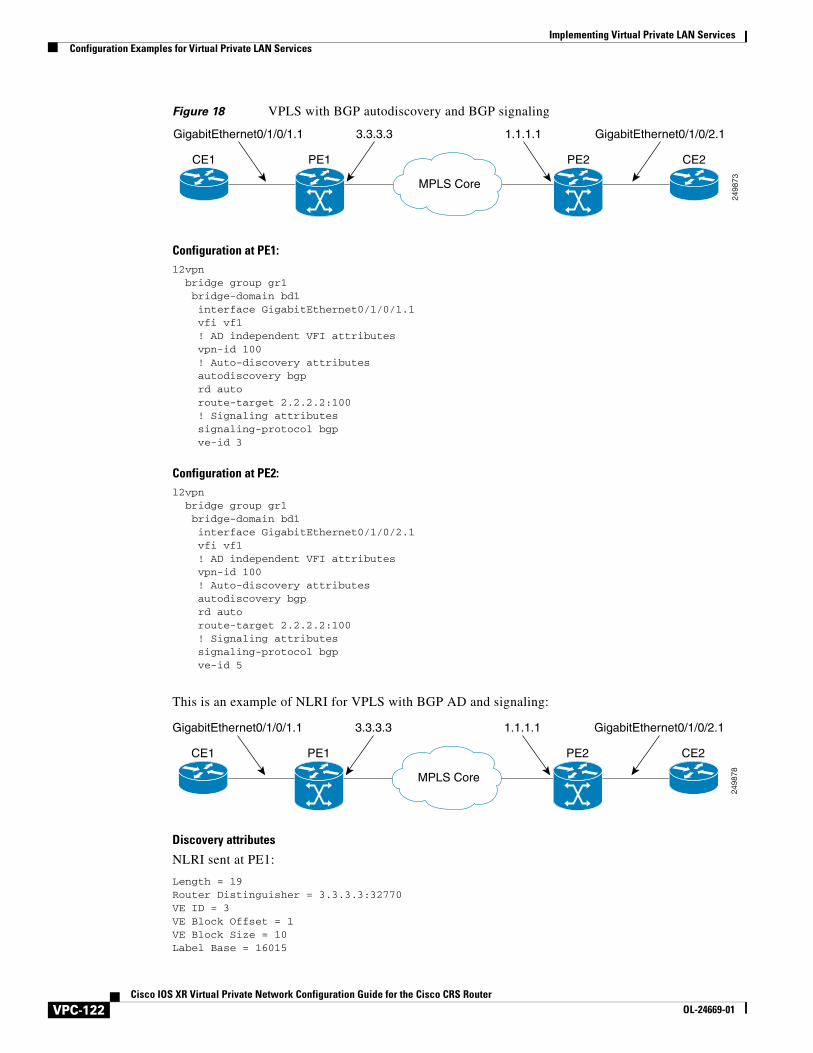
Implementing Virtual Private LAN Services Configuration Examples for Virtual Private LAN Services
Figure 18 VPLS with BGP autodiscovery and BGP signaling
Configuration at PE1:l2vpn bridge group gr1 bridge-domain bd1 interface GigabitEthernet0/1/0/1.1 vfi vf1 ! AD independent VFI attributes vpn-id 100 ! Auto-discovery attributes autodiscovery bgp rd auto route-target 2.2.2.2:100 ! Signaling attributes signaling-protocol bgp ve-id 3
Configuration at PE2:l2vpn bridge group gr1 bridge-domain bd1 interface GigabitEthernet0/1/0/2.1 vfi vf1 ! AD independent VFI attributes vpn-id 100 ! Auto-discovery attributes autodiscovery bgp rd auto route-target 2.2.2.2:100 ! Signaling attributes signaling-protocol bgp ve-id 5
This is an example of NLRI for VPLS with BGP AD and signaling:
Discovery attributes
NLRI sent at PE1:
Length = 19Router Distinguisher = 3.3.3.3:32770VE ID = 3VE Block Offset = 1VE Block Size = 10Label Base = 16015
2498
73MPLS Core
CE1 PE1 PE2 CE2
3.3.3.3GigabitEthernet0/1/0/1.1 1.1.1.1 GigabitEthernet0/1/0/2.1
2498
78MPLS Core
CE1 PE1 PE2 CE2
3.3.3.3GigabitEthernet0/1/0/1.1 1.1.1.1 GigabitEthernet0/1/0/2.1
VPC-122Cisco IOS XR Virtual Private Network Configuration Guide for the Cisco CRS Router
OL-24669-01
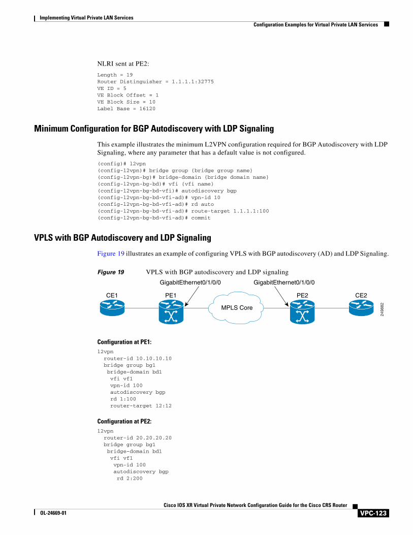
Implementing Virtual Private LAN ServicesConfiguration Examples for Virtual Private LAN Services
NLRI sent at PE2:
Length = 19Router Distinguisher = 1.1.1.1:32775VE ID = 5VE Block Offset = 1VE Block Size = 10Label Base = 16120
Minimum Configuration for BGP Autodiscovery with LDP Signaling
This example illustrates the minimum L2VPN configuration required for BGP Autodiscovery with LDP Signaling, where any parameter that has a default value is not configured.
(config)# l2vpn(config-l2vpn)# bridge group {bridge group name}(config-l2vpn-bg)# bridge-domain {bridge domain name}(config-l2vpn-bg-bd)# vfi {vfi name}(config-l2vpn-bg-bd-vfi)# autodiscovery bgp(config-l2vpn-bg-bd-vfi-ad)# vpn-id 10(config-l2vpn-bg-bd-vfi-ad)# rd auto(config-l2vpn-bg-bd-vfi-ad)# route-target 1.1.1.1:100(config-l2vpn-bg-bd-vfi-ad)# commit
VPLS with BGP Autodiscovery and LDP Signaling
Figure 19 illustrates an example of configuring VPLS with BGP autodiscovery (AD) and LDP Signaling.
Figure 19 VPLS with BGP autodiscovery and LDP signaling
Configuration at PE1:l2vpn router-id 10.10.10.10 bridge group bg1 bridge-domain bd1 vfi vf1 vpn-id 100 autodiscovery bgp rd 1:100 router-target 12:12
Configuration at PE2:l2vpn router-id 20.20.20.20 bridge group bg1 bridge-domain bd1 vfi vf1 vpn-id 100 autodiscovery bgp rd 2:200
2498
82MPLS Core
CE1 PE1 PE2 CE2
GigabitEthernet0/1/0/0 GigabitEthernet0/1/0/0
VPC-123Cisco IOS XR Virtual Private Network Configuration Guide for the Cisco CRS Router
OL-24669-01
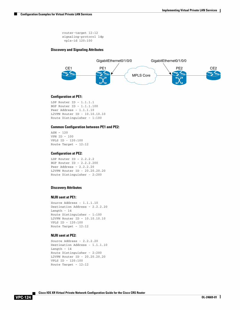
Implementing Virtual Private LAN Services Configuration Examples for Virtual Private LAN Services
router-target 12:12 signaling-protocol ldp vpls-id 120:100
Discovery and Signaling Attributes
Configuration at PE1:LDP Router ID - 1.1.1.1BGP Router ID - 1.1.1.100Peer Address - 1.1.1.10L2VPN Router ID - 10.10.10.10Route Distinguisher - 1:100
Common Configuration between PE1 and PE2:ASN - 120VPN ID - 100VPLS ID - 120:100Route Target - 12:12
Configuration at PE2:LDP Router ID - 2.2.2.2BGP Router ID - 2.2.2.200Peer Address - 2.2.2.20L2VPN Router ID - 20.20.20.20Route Distinguisher - 2:200
Discovery Attributes
NLRI sent at PE1:Source Address - 1.1.1.10Destination Address - 2.2.2.20Length - 14Route Distinguisher - 1:100L2VPN Router ID - 10.10.10.10VPLS ID - 120:100Route Target - 12:12
NLRI sent at PE2:Source Address - 2.2.2.20Destination Address - 1.1.1.10Length - 14Route Distinguisher - 2:200L2VPN Router ID - 20.20.20.20VPLS ID - 120:100Route Target - 12:12
MPLS Core
CE1 PE1 PE2 CE2
GigabitEthernet0/1/0/0 GigabitEthernet0/1/0/0
VPC-124Cisco IOS XR Virtual Private Network Configuration Guide for the Cisco CRS Router
OL-24669-01
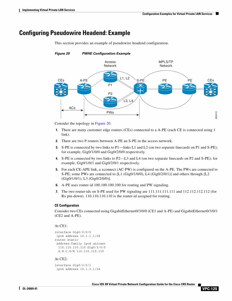
Implementing Virtual Private LAN ServicesConfiguration Examples for Virtual Private LAN Services
Configuring Pseudowire Headend: ExampleThis section provides an example of pseudowire headend configuration.
Figure 20 PWHE Configuration Example
Consider the topology in Figure 20.
1. There are many customer edge routers (CEs) connected to a A-PE (each CE is connected using 1 link).
2. There are two P routers between A-PE an S-PE in the access network.
3. S-PE is connected by two links to P1—links L1 and L2 (on two separate linecards on P1 and S-PE); for example, Gig0/1/0/0 and Gig0/2/0/0 respectively.
4. S-PE is connected by two links to P2—L3 and L4 (on two separate linecards on P2 and S-PE); for example, Gig0/1/0/1 and Gig0/2/0/1 respectively.
5. For each CE-APE link, a xconnect (AC-PW) is configured on the A-PE. The PWs are connected to S-PE; some PWs are connected to [L1 (Gig0/1/0/0), L4 (Gig0/2/0/1)] and others through [L2 (Gig0/1/0/1), L3 (Gig0/2/0/0)].
6. A-PE uses router-id 100.100.100.100 for routing and PW signaling.
7. The two router-ids on S-PE used for PW signaling are 111.111.111.111 and 112.112.112.112 (for Rx pin-down). 110.110.110.110 is the router-id assigned for routing.
CE Configuration
Consider two CEs connected using GigabitEthernet0/3/0/0 (CE1 and A-PE) and GigabitEthernet0/3/0/1 (CE2 and A-PE).
At CE1:
interface Gig0/3/0/0 ipv4 address 10.1.1.1/24router static address-family ipv4 unicast 110.110.110.110 Gig0/3/0/0 A.B.C.D/N 110.110.110.110
At CE2:
interface Gig0/3/0/1 ipv4 address 10.1.2.1/24
MPLS/TPNetwork
AccessNetwork
2824
19
P2
P1S-PEA-PE PE PECEs CEx
L3, L4
L1, L2
ACsPWs
VPC-125Cisco IOS XR Virtual Private Network Configuration Guide for the Cisco CRS Router
OL-24669-01
Implementing Virtual Private LAN Services Configuration Examples for Virtual Private LAN Services
router static address-family ipv4 unicast 110.110.110.110 Gig0/3/0/1 A.B.C.D/N 110.110.110.110
A-PE Configuration
At A-PE, one xconnect is configured for each CE connection. Here, CE connections are L2 links, which are in xconnects. Each xconnect has a pseudowire connected to S-PE, though connected to different neighbor addresses, depending on where the pseudowire is to be pin downed: [L1, L4] or [L2, L3].
interface Gig0/3/0/0 l2transportinterface Gig0/3/0/1 l2transport
l2vpn xconnect group pwhe p2p pwhe_spe_1 interface Gig0/3/0/0 neighbor 111.111.111.111 pw-id 1 p2p pwhe_spe_2 interface Gig0/3/0/1 neighbor 112.112.112.112 pw-id 2
P Router Configuration
Static routes are required on P routers for Rx pindown on S-PE to force PWs configured with a specific address to be transported over certain links.
At P1:
router static address-family ipv4 unicast 111.111.111.111 Gig0/1/0/0 112.112.112.112 Gig0/2/0/0
At P2:
router static address-family ipv4 unicast 111.111.111.111 Gig0/2/0/1 112.112.112.112 Gig0/1/0/1
S-PE Configuration
At S-PE, two PWHE interfaces (one for each PW) is configured, and each uses a different interface list for Tx pin-down. (This must match the static configuration at P routers for Rx pin-down). Each PWHE has the PW connected to A-PE (The pw-id must match the pw-id at A-PE.)
generic-interface-list il1 interface gig0/1/0/0 interface gig0/2/0/0generic-interface-list il2 interface gig0/1/0/1 interface gig0/2/0/1
interface pw-ether1 ipv4 address 10.1.1.2/24 attach generic-interface-list il1
VPC-126Cisco IOS XR Virtual Private Network Configuration Guide for the Cisco CRS Router
OL-24669-01
Implementing Virtual Private LAN ServicesAdditional References
interface pw-ether2 ipv4 address 10.1.2.2/24 attach generic-interface-list il2
l2vpn xconnect group pwhe p2p pwhe1 interface pw-ether1 neighbor 100.100.100.100 pw-id 1 p2p pwhe2 interface pw-ether2 neighbor 100.100.100.100 pw-id 2
Additional ReferencesFor additional information related to implementing VPLS, refer to the following references:
Related Documents
Standards
Related Topic Document Title
Cisco IOS XR L2VPN command reference document MPLS Virtual Private Network Commands on Cisco IOS XR Software module in Cisco IOS XR MPLS Command Reference
MPLS VPLS-related commands MPLS Virtual Private LAN Services Commands on Cisco IOS XR Software module in Cisco IOS XR MPLS Command Reference
MPLS Layer 2 VPNs Implementing MPLS Layer 2 VPNs on Cisco IOS XR Software module in Cisco IOS XR MPLS Configuration Guide
MPLS VPNs over IP Tunnels MPLS VPNs over IP Tunnels on Cisco IOS XR Software module in Cisco IOS XR MPLS Configuration Guide
Cisco CRS router getting started material Cisco IOS XR Getting Started Guide
Information about user groups and task IDs Configuring AAA Services on Cisco IOS XR Software module of Cisco IOS XR System Security Configuration Guide
Standards1
1. Not all supported standards are listed.
Title
No new or modified standards are supported by this feature, and support for existing standards has not been modified by this feature.
—
VPC-127Cisco IOS XR Virtual Private Network Configuration Guide for the Cisco CRS Router
OL-24669-01
Implementing Virtual Private LAN Services Additional References
MIBs
RFCs
Technical Assistance
MIBs MIBs Link
— To locate and download MIBs using Cisco IOS XR software, use the Cisco MIB Locator found at the following URL and choose a platform under the Cisco Access Products menu: http://cisco.com/public/sw-center/netmgmt/cmtk/mibs.shtml
RFCs Title
RFC 3931 Layer Two Tunneling Protocol - Version 3 (L2TPv3)
RFC 4447 Pseudowire Setup and Maintenance Using the Label Distribution Protocol (LDP), April 2006
RFC 4448 Encapsulation Methods for Transport of Ethernet over MPLS Networks, April 2006
Description Link
The Cisco Technical Support website contains thousands of pages of searchable technical content, including links to products, technologies, solutions, technical tips, and tools. Registered Cisco.com users can log in from this page to access even more content.
http://www.cisco.com/techsupport
VPC-128Cisco IOS XR Virtual Private Network Configuration Guide for the Cisco CRS Router
OL-24669-01