Embed Size (px)
Citation preview

International Journal of Computing and Corporate Research
ISSN (Online) : 2249-054X
Volume 3 Issue 6 November 2013
International Manuscript ID : 2249054XV3I6112013-05
1
IMPLEMENTING SC-FDMA &OFDMA IN MATLAB
Murtadha Ali Nsaif Shukur 1, Dr. Kuldip Pahwa 2, Er. Ankur Singhal 3
1. M.Tech.(ECE) Scholar, M. M. University, Mullana, Haryana, India
2. Professor, M. M. University, Mullana, Haryana, India
3. Assistant Professor, M. M. University, Mullana, Haryana, India
Abstract
It is very challenging to design an efficient wireless communication system. It is because
of many factors, affecting the performance of a typical wireless communication system.
Single Carrier Frequency Division Multiple Access (SC-FDMA) & Orthogonal Division
Multiple Access (OFDMA) are a major part of future mobile communication standards
like Long Term Evolution (LTE), LTE-Advanced and Ultra Mobile Broadband (UMB).
OFDMA is well utilized for achieving high spectral efficiency in communication systems.
SC-FDMA was recently introduced for uplink multiple access scheme. The multiple
access schemes in an advanced mobile radio system have to meet the challenging
requirements, such as high throughput, good robustness, low Bit Error Rate (BER), high
spectral efficiency, low delays, low computational complexity, low Peak to Average
Power Ratio (PAPR) and low error probability. Therefore, this project focuses on
implementing the two multiple access techniques (SC-FDMA and OFDMA) with adaptive
modulation techniques BPSK, QPSK, 16-QAM and 64-QAM; in order to evaluate the
performance of LTE physical layer. An introduction to LTE systems is presented in this
manuscript.
Keywords : OFDMA, SC- FDMA, LTE, BER, PAPR, MATLAB.
International Journal of Computing and Corporate Research
ISSN (Online) : 2249-054X
Volume 3 Issue 6 November 2013
International Manuscript ID : 2249054XV3I6112013-05
2
Introduction
To globally standardize the telecommunication, an organization known International
Telegraph Union (ITU) (presently, International Telecommunication Union), was
established in Switzerland in 1865 [1]. Since then, ITU has been involved in developing
global standards; from telegraphs to modern age 4G systems. Recently, in 2000, to
satisfy the ITU’s 3rd generation mobile system standards, an organization 3rd
Generation Partnership Project (3GPP) was formed. 3GPP is a collaboration of groups
of telecom associations working on Global System for Mobile Communication (GSM) [1].
3GPP published and introduced the various standards for IP based system in Release 8,
which was also termed Long Term Evolution and abbreviated as LTE. Recently in 2011,
LTE was further developed through Release 10 to satisfy ITU’s IMT-Advanced
requirements for 4G cellular systems. LTE radio transmission and reception
specifications are documented in TS 36.101 for the UE (User Equipment) and TS 36.104
for the eNB (Evolved Node B). As per these specifications, LTE is capable of supporting
up to 1Giga Bits per second (1Gbps) for fixed user and up to 100 Mega Bits per second
(100 Mbps) for high speed user [1]. The prime cause of this high speed of LTE systems
is the advancement in physical layer.
Although there are major step changes between LTE and its 3G predecessors, it is
nevertheless looked upon as an evolution of the UMTS/3GPP 3G standards as shown in
the Table 1.1. Although LTE uses a different form of radio interface using OFDMA/SC-
FDMA instead of CDMA; yet there are many similarities with the earlier forms of 3G
architecture and there is scope for much re-use. LTE can, therefore, be seen to provide
a further evolution of functionality, increased speeds and general improved performance.

International Journal of Computing and Corporate Research
ISSN (Online) : 2249-054X
Volume 3 Issue 6 November 2013
International Manuscript ID : 2249054XV3I6112013-05
3
WCDMA
(UMTS)
HSPA
HSDPA/HSUPA
HSPA+ LTE
Max downlink speed 384Kbps 14Mbps 28Mbps 100Mbps
Max uplink speed 128Kbps 5.7Mbps 11Mbps 50Mbps
Latency round trip
time
150ms 100ms 50ms (max) ~10ms
3GPP releases Rel 99/4 Rel 5/6 Rel 7 Rel 8/10
Approx years of initial
roll out
2003/04 2005/06 (HSDPA)
2007/08 (HSUPA)
2008/09 2009/10
Access technology CDMA CDMA CDMA OFDMA/
SC-FDMA
Table 1.1: Comparison of parameters of UMTS, HSPA, HSPA+ and LTE [1-3].
In addition to this, LTE is an all IP based network, supporting both IPv4 and IPv6. There
is also no basic provision for voice; although, this can be carried as VoIP.
LTE Specifications
The detailed specification of LTE is given in Table 1.2.
Specification Details
Peak downlink speed
64QAM (Mbps)
100 (SISO), 172 (2x2 MIMO), 326 (4x4 MIMO)
Peak uplink speed (Mbps) 50 (QPSK), 57 (16QAM), 86 (64QAM)
Data type All packet switched data (voice and data). No circuit
switched.
Channel bandwidths 1.4, 3, 5, 10, 15 and 20 MHz
Duplex schemes FDD and TDD
Mobility 0-15 Km/h optimized
15 - 120 Km/hr (high performance)

International Journal of Computing and Corporate Research
ISSN (Online) : 2249-054X
Volume 3 Issue 6 November 2013
International Manuscript ID : 2249054XV3I6112013-05
4
Latency Idle to active less than 100 ms
Small packets ~10 ms
Spectral Efficiency Downlink: 3 to 4 x HSDPA Rel. 6
Uplink: 2 to 3 x HSUPA Rel. 6
Supported antenna
configurations
Downlink: 4x2, 2x2, 1x2, 1x1
Uplink: 1x2, 1x1
Access schemes OFDMA (downlink)
SC-FDMA (uplink)
Modulation types supported QPSK, 16QAM, 64QAM (Uplink and downlink)
Coverage
Full performance up to 5 Km
Slight degradation 5 Km – 30 Km
Operation up to 100 Km should not be precluded by
standard
Table 1.2: Specification of LTE [1-3].
Review of Literature
The LTE physical layer is designed for maximum efficiency of the packet-based
transmission; thus only shared channels exist in the physical layer to enable dynamic
resource utilization. Different bandwidths ranging from 1.4 MHz to 20MHz are used and
parameters are chosen in such a way that FFT lengths as well as sampling rates are
obtained easily for all operation modes. All resource allocations are usually short-term.
The downlink transmission also contains the control information required for the uplink
resources.
The LTE frame structure in the physical layer is comprised of two types:
• Type-1 LTE Frequency Division Duplex (FDD) mode systems
• Type-2 LTE Time Division Duplex (TDD) mode systems
Type-1 frame structure works on both half duplex and full duplex FDD modes. This type
of radio frame has duration of 10ms and consists of 20 slots, each slot has equal
International Journal of Computing and
International Manuscript ID : 2249054XV3I6112013
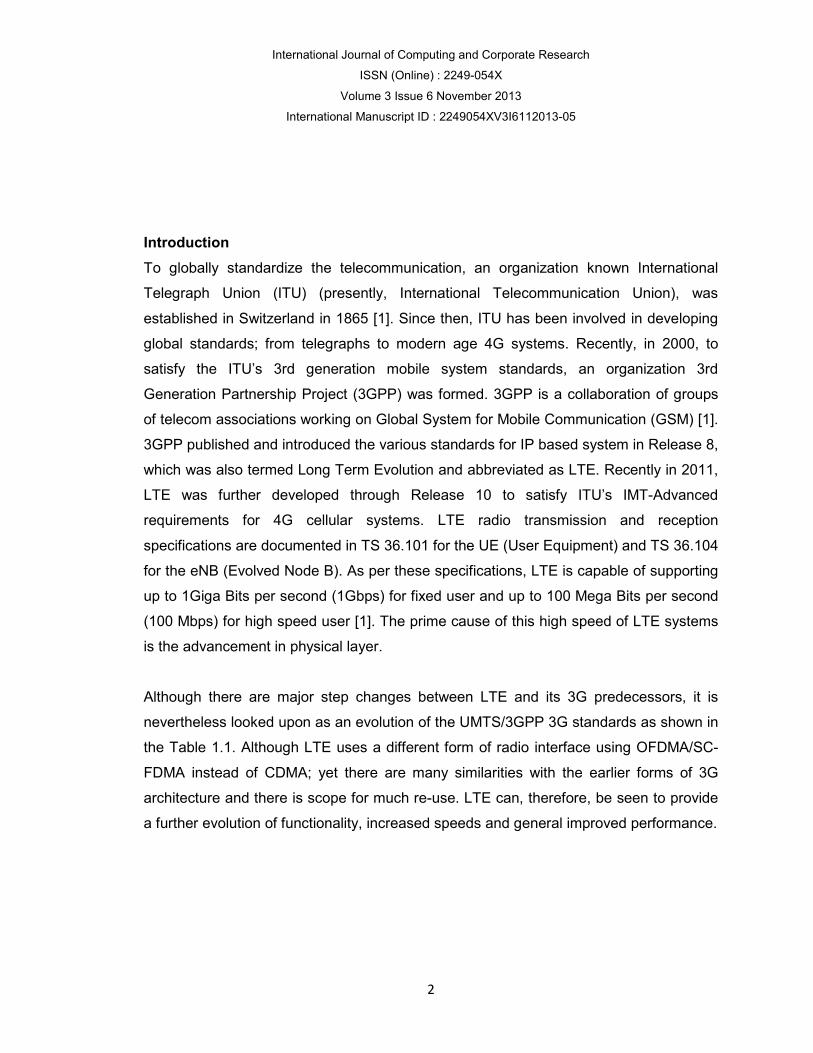
duration of 0.5ms [9]. A sub
10 sub-frames as shown in Figure 2.1. In FDD mode, downlink and uplink transmission
is divided in frequency domain; such that, half of the total sub
downlink and half for uplink, in each radio frame interval of 1
Figure 2.1: Type
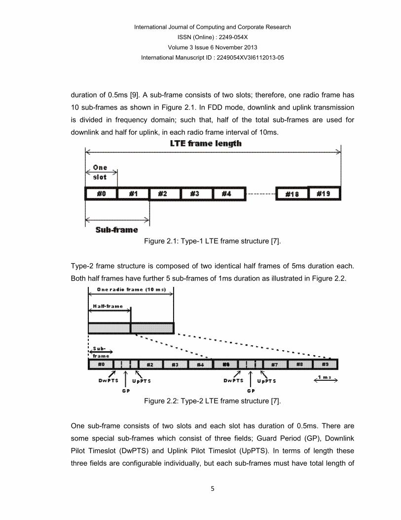
Type-2 frame structure is composed of two identical half frames of 5ms duration each.
Both half frames have further 5 sub
Figure 2.2: Type
One sub-frame consists of two slots and each slot has duration of 0.5ms. There are
some special sub-frames which consist of three fields; Guard Period (GP), Downlink
Pilot Timeslot (DwPTS) and Uplink Pilot Timeslot (UpPTS). In terms o
three fields are configurable individually, but each sub
International Journal of Computing and Corporate Research
ISSN (Online) : 2249-054X
Volume 3 Issue 6 November 2013
International Manuscript ID : 2249054XV3I6112013-05
5
duration of 0.5ms [9]. A sub-frame consists of two slots; therefore, one radio frame has
frames as shown in Figure 2.1. In FDD mode, downlink and uplink transmission
is divided in frequency domain; such that, half of the total sub-frames are used for
downlink and half for uplink, in each radio frame interval of 10ms.
Figure 2.1: Type-1 LTE frame structure [7].
2 frame structure is composed of two identical half frames of 5ms duration each.
Both half frames have further 5 sub-frames of 1ms duration as illustrated in Figure 2.2.
Figure 2.2: Type-2 LTE frame structure [7].
frame consists of two slots and each slot has duration of 0.5ms. There are
frames which consist of three fields; Guard Period (GP), Downlink
Pilot Timeslot (DwPTS) and Uplink Pilot Timeslot (UpPTS). In terms o
three fields are configurable individually, but each sub-frames must have total length of
re, one radio frame has
frames as shown in Figure 2.1. In FDD mode, downlink and uplink transmission
frames are used for
2 frame structure is composed of two identical half frames of 5ms duration each.
frames of 1ms duration as illustrated in Figure 2.2.
frame consists of two slots and each slot has duration of 0.5ms. There are
frames which consist of three fields; Guard Period (GP), Downlink
Pilot Timeslot (DwPTS) and Uplink Pilot Timeslot (UpPTS). In terms of length these
frames must have total length of

International Journal of Computing and
International Manuscript ID : 2249054XV3I6112013
1ms. There are seven uplink/downlink configurations used for either 5ms or 10ms
switch-point periodicities. A special sub
switch-point periodicity; whereas, for 10ms switch
exists only in the first half
Time and frequency resources of the available bandwidth are divided into smaller blocks
to support multiuser configuration and improve overall system efficiency. As LTE
DownLink (DL) uses OFDMA and UpLink (UL) supports SC
bandwidth is divided into number of orthogonal frequencies with a spacing of
∆f = 15KHz called subcarriers [8]. This subcarrier spacing of 15KHz helps keeping Inter
Carrier Interference (ICI) to the lower level even the mobile is moving with high speed
and causing high Doppler shifts in the frequency [8].
A Resource Block (RB) or sub
subcarriers and 12 or 14 OFDM symbols (depending on the Cyclic Prefix (CP) length).
Figure 2.3: LTE radio frame structure with 72 subcarriers with ∆f = 15KHz [10].
International Journal of Computing and Corporate Research
ISSN (Online) : 2249-054X
Volume 3 Issue 6 November 2013
International Manuscript ID : 2249054XV3I6112013-05
6
1ms. There are seven uplink/downlink configurations used for either 5ms or 10ms
point periodicities. A special sub-frame exists in both half frames in case of 5ms
point periodicity; whereas, for 10ms switch-point periodicity the special frame
exists only in the first half-frame.
Time and frequency resources of the available bandwidth are divided into smaller blocks
configuration and improve overall system efficiency. As LTE
DownLink (DL) uses OFDMA and UpLink (UL) supports SC-OFDMA, the available
bandwidth is divided into number of orthogonal frequencies with a spacing of
carriers [8]. This subcarrier spacing of 15KHz helps keeping Inter
Carrier Interference (ICI) to the lower level even the mobile is moving with high speed
and causing high Doppler shifts in the frequency [8].
A Resource Block (RB) or sub-frame (Figure 2.3) is formed of a length 1ms using 12
subcarriers and 12 or 14 OFDM symbols (depending on the Cyclic Prefix (CP) length).
Figure 2.3: LTE radio frame structure with 72 subcarriers with ∆f = 15KHz [10].
1ms. There are seven uplink/downlink configurations used for either 5ms or 10ms
ames in case of 5ms
point periodicity the special frame
Time and frequency resources of the available bandwidth are divided into smaller blocks
configuration and improve overall system efficiency. As LTE
OFDMA, the available
bandwidth is divided into number of orthogonal frequencies with a spacing of
carriers [8]. This subcarrier spacing of 15KHz helps keeping Inter
Carrier Interference (ICI) to the lower level even the mobile is moving with high speed
) is formed of a length 1ms using 12
subcarriers and 12 or 14 OFDM symbols (depending on the Cyclic Prefix (CP) length).
Figure 2.3: LTE radio frame structure with 72 subcarriers with ∆f = 15KHz [10].
International Journal of Computing and
International Manuscript ID : 2249054XV3I6112013
Furthermore, the RB is subdivided into two slots
symbols over 12 subcarriers. Such fine granularity of the time and frequency resources
helps network to assign one or more RBs to different active users simultaneously
depending upon the channel conditions and other fa
grouped together to form the radio resources.
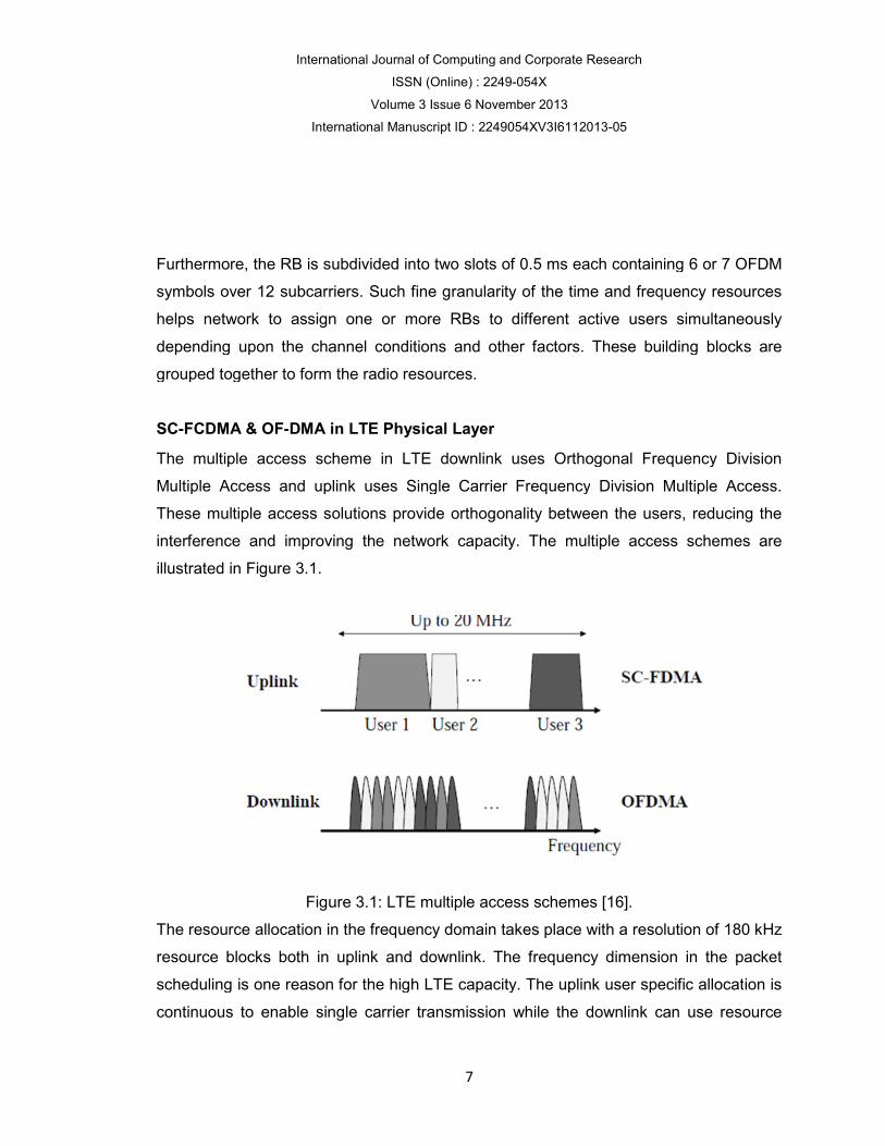
SC-FCDMA & OF-DMA in LTE Physical Layer
The multiple access scheme in LTE downlink uses Orthogonal Frequency Division
Multiple Access and uplink uses Single Carrier Frequency
These multiple access solutions provide orthogonality between the users, reducing the
interference and improving the network capacity. The multiple access schemes are
illustrated in Figure 3.1.
Figure 3.1: LTE multiple access
The resource allocation in the frequency domain takes place with a resolution of 180 kHz
resource blocks both in uplink and downlink. The frequency dimension in the packet
scheduling is one reason for the high LTE capacity. The uplink user specific allocat
continuous to enable single carrier transmission while the downlink can use resource
International Journal of Computing and Corporate Research
ISSN (Online) : 2249-054X
Volume 3 Issue 6 November 2013
International Manuscript ID : 2249054XV3I6112013-05
7
Furthermore, the RB is subdivided into two slots of 0.5 ms each containing 6 or 7 OFDM
symbols over 12 subcarriers. Such fine granularity of the time and frequency resources
helps network to assign one or more RBs to different active users simultaneously
depending upon the channel conditions and other factors. These building blocks are
grouped together to form the radio resources.
DMA in LTE Physical Layer
The multiple access scheme in LTE downlink uses Orthogonal Frequency Division
Multiple Access and uplink uses Single Carrier Frequency Division Multiple Access.
These multiple access solutions provide orthogonality between the users, reducing the
interference and improving the network capacity. The multiple access schemes are
Figure 3.1: LTE multiple access schemes [16].
The resource allocation in the frequency domain takes place with a resolution of 180 kHz
resource blocks both in uplink and downlink. The frequency dimension in the packet
scheduling is one reason for the high LTE capacity. The uplink user specific allocat
continuous to enable single carrier transmission while the downlink can use resource
of 0.5 ms each containing 6 or 7 OFDM
symbols over 12 subcarriers. Such fine granularity of the time and frequency resources
helps network to assign one or more RBs to different active users simultaneously
ctors. These building blocks are
The multiple access scheme in LTE downlink uses Orthogonal Frequency Division
Division Multiple Access.
These multiple access solutions provide orthogonality between the users, reducing the
interference and improving the network capacity. The multiple access schemes are
The resource allocation in the frequency domain takes place with a resolution of 180 kHz
resource blocks both in uplink and downlink. The frequency dimension in the packet
scheduling is one reason for the high LTE capacity. The uplink user specific allocation is
continuous to enable single carrier transmission while the downlink can use resource
International Journal of Computing and Corporate Research
ISSN (Online) : 2249-054X
Volume 3 Issue 6 November 2013
International Manuscript ID : 2249054XV3I6112013-05
8
blocks freely from different parts of the spectrum. The uplink single carrier solution is
also designed to allow efficient terminal power amplifier design, which is relevant for the
terminal battery life. The LTE solution enables spectrum flexibility where the
transmission bandwidth can be selected between 1.4 MHz and 20 MHz depending on
the available spectrum. The 20 MHz bandwidth can provide up to 150 Mbps downlink
user data rate with 2 × 2 MIMO, and 300 Mbps with 4 × 4 MIMO. The uplink peak data
rate is 75 Mbps.
LTE increases the system capacity and widens the spectrum from existing technology
up to 20MHz. It can be deployed in any bandwidth combination because of its flexible
usage of spectrum (1.4 MHz to 20 MHz). It uses Frequency Division Duplex (FDD) and
Time Division Duplex (TDD) to suit all types of spectrum resources. The main
requirements for designing the LTE systems are summarized as:
• Date Rate: For 20 MHz spectrum, the target for peak data rate is 50 Mbps (for
uplink) and 100 Mbps (for downlink).
• Bandwidth: In 3GPP technology family, there were considered both the wideband
(WCDMA with 5MHz) and the narrowband (GSM with 200 kHz). Therefore, the new
system is now required to facilitate frequency allocation flexibility with 1.25/2.5, 5, 10,
15 and 20 MHz allocations [7].
• Peak Spectral Efficiency: The peak spectral efficiency requirement for downlink is
5 bps/Hz or higher, and for uplink is 2.5 bps/Hz or higher.
• Spectral Efficiency of Cell Edge: The requirement for spectral efficiency of cell
edge is 0.04-0.06 bps/Hz/user for downlink and 0.02-0.03 bps/Hz/user for uplink,
with assumption of 10 users/cell.
• Average Cell Spectral Efficiency: The average cell spectral efficiency required for
downlink is 1.6-2.1 bps/Hz/cell and for uplink it is 0.66-1.0 bps/Hz/cell.
• Latency: The LTE control-plane latency (transition time to active state) is less than
100 ms (for idle to active), and is less than 50 ms (for dormant to active). The user-
plane latency is less than 10 ms from UE (user end) to server.

International Journal of Computing and Corporate Research
ISSN (Online) : 2249-054X
Volume 3 Issue 6 November 2013
International Manuscript ID : 2249054XV3I6112013-05
9
• Security & Mobility: Security and mobility in 3GPP technology is used at good level
with the earlier systems starting from GSM and it is sustained at that level and
higher.
Simulation Results
This simulates model of OFDMA and SC-FDMA in Matlab. The block diagrams of
OFDMA and SC-FDMA are shown in Figure 4.1 and Figure 4.2 respectively, below. The
block diagrams of OFDMA and SC-FDMA are similar to OFDM system, except the
additional subcarrier mapping and the position of some blocks.
Figure 4.1: Block diagram of an OFDMA system.
Figure 4.2: Block diagram of a SC-FDMA system.
BER vs SNR of OFDMA and SC-FDMA
The BER vs SNR of OFDMA and SC-FDMA are shown in Figures 4.3 & 4.4 and the
corresponding values in Tables 4.2 and 4.3 respectively. In Tables 4.1 and 4.2, the
observations are taken for a specific value of BER (1e-3). In both OFDMA and SC-

International Journal of Computing and
International Manuscript ID : 2249054XV3I6112013
FDMA, the BPSK and QPSK have same SNR values of 6.8 and 6.5 respectively, but a
sudden change occur in 16
(16.4) which shows that 64
Figure 4.3: BER vs SNR of OFDMA with Adaptive Modulation.
International Journal of Computing and Corporate Research
ISSN (Online) : 2249-054X
Volume 3 Issue 6 November 2013
International Manuscript ID : 2249054XV3I6112013-05
10
FDMA, the BPSK and QPSK have same SNR values of 6.8 and 6.5 respectively, but a
den change occur in 16-QAM and 64-QAM. The 64-QAM has highest value of SNR
(16.4) which shows that 64-QAM is more efficient in terms BER.
.3: BER vs SNR of OFDMA with Adaptive Modulation.
FDMA, the BPSK and QPSK have same SNR values of 6.8 and 6.5 respectively, but a
QAM has highest value of SNR
.3: BER vs SNR of OFDMA with Adaptive Modulation.

International Journal of Computing and Corporate Research
ISSN (Online) : 2249-054X
Volume 3 Issue 6 November 2013
International Manuscript ID : 2249054XV3I6112013-05
11
Figure 4.4: BER vs SNR of SC-FDMA with Adaptive Modulation.
BER =1e-3
Modulation Scheme Bits per Symbol SNR (dB)
BPSK 1 6.8
QPSK 2 6.8
16-QAM 4 11.6
64-QAM 6 16. 4
Table 4.2: BER vs SNR for OFDMA.
BER =1e-3
Modulation Scheme Bits per Symbol SNR (dB)
BPSK 1 6.5
QPSK 2 6.5

International Journal of Computing and Corporate Research
ISSN (Online) : 2249-054X
Volume 3 Issue 6 November 2013
International Manuscript ID : 2249054XV3I6112013-05
12
16-QAM 4 11.7
64-QAM 6 16. 4
Table 4.3: BER vs SNR for SC-FDMA.
Error Probability of OFDMA and SC-FDMA for Adaptive Modulation
The error probability graphs of OFDMA and SC-FDMA are shown in Figures 4.5 and
4.6, and the corresponding values in Tables 4.4 and 4.5 respectively.
Figure 4.5: Error probability of OFDMA.
International Journal of Computing and Corporate Research
ISSN (Online) : 2249-054X
Volume 3 Issue 6 November 2013
International Manuscript ID : 2249054XV3I6112013-05
13
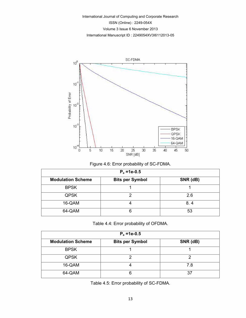
Figure 4.6: Error probability of SC-FDMA.
Pe =1e-0.5
Modulation Scheme Bits per Symbol SNR (dB)
BPSK 1 1
QPSK 2 2.6
16-QAM 4 8. 4
64-QAM 6 53
Table 4.4: Error probability of OFDMA.
Pe =1e-0.5
Modulation Scheme Bits per Symbol SNR (dB)
BPSK 1 1
QPSK 2 2
16-QAM 4 7.8
64-QAM 6 37
Table 4.5: Error probability of SC-FDMA.

International Journal of Computing and Corporate Research
ISSN (Online) : 2249-054X
Volume 3 Issue 6 November 2013
International Manuscript ID : 2249054XV3I6112013-05
14
From Tables 4.4 and 4.5, it can be seen that for a specific value of Pe (1e-0.5) the BPSK
modulation has less value of SNR as compared to other modulations. The 64-QAM has
higher SNR values in both OFDMA and SC-FDMA.
Power Spectral Density of OFDMA and SC-FDMA:
The power spectral density of OFDMA and SC-FDMA are shown in figure 4.7 and figure
4.8 respectively.
Figure 4.7: Power Spectral Density of OFDMA
International Journal of Computing and Corporate Research
ISSN (Online) : 2249-054X
Volume 3 Issue 6 November 2013
International Manuscript ID : 2249054XV3I6112013-05
15
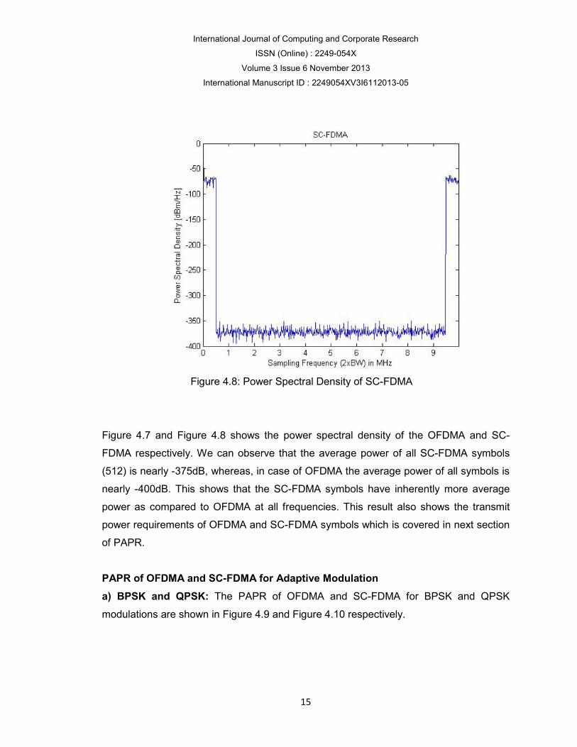
Figure 4.8: Power Spectral Density of SC-FDMA
Figure 4.7 and Figure 4.8 shows the power spectral density of the OFDMA and SC-
FDMA respectively. We can observe that the average power of all SC-FDMA symbols
(512) is nearly -375dB, whereas, in case of OFDMA the average power of all symbols is
nearly -400dB. This shows that the SC-FDMA symbols have inherently more average
power as compared to OFDMA at all frequencies. This result also shows the transmit
power requirements of OFDMA and SC-FDMA symbols which is covered in next section
of PAPR.
PAPR of OFDMA and SC-FDMA for Adaptive Modulation
a) BPSK and QPSK: The PAPR of OFDMA and SC-FDMA for BPSK and QPSK
modulations are shown in Figure 4.9 and Figure 4.10 respectively.

International Journal of Computing and
International Manuscript ID : 2249054XV3I6112013
Figure 4
Figure 4
From Figure 4.9 and Figure
is almost similar for both modulation schemes; whereas, the PAPR value of
slightly decreases in case of QPSK modulation.
International Journal of Computing and Corporate Research
ISSN (Online) : 2249-054X
Volume 3 Issue 6 November 2013
International Manuscript ID : 2249054XV3I6112013-05
16
4.9: PAPR of OFDMA and SC-FDMA for BPSK.
4.10: PAPR of OFDMA and SC-FDMA for QPSK
.9 and Figure 4.10, it can be observed that the PAPR value of SC
is almost similar for both modulation schemes; whereas, the PAPR value of
slightly decreases in case of QPSK modulation.
FDMA for QPSK
.10, it can be observed that the PAPR value of SC-FDMA
is almost similar for both modulation schemes; whereas, the PAPR value of OFDMA

International Journal of Computing and Corporate Research
ISSN (Online) : 2249-054X
Volume 3 Issue 6 November 2013
International Manuscript ID : 2249054XV3I6112013-05
17
b) 16-QAM and 64-QAM: The PAPR of OFDMA and SC-FDMA for 16-QAM and
64-QAM are shown in Figures 4.11 and 4.12 respectively.
Figure 4.11: PAPR of OFDMA and SC-FDMA for 16-QAM.
Figure 4.12: PAPR of OFDMA and SC-FDMA for 64-QAM.
From Figures 4.11 and 4.12, it can be observed that by increasing the order of
modulation, the PAPR of SC-FDMA increases from 7.5 dB to 8 dB (in case of 16-QAM)

International Journal of Computing and Corporate Research
ISSN (Online) : 2249-054X
Volume 3 Issue 6 November 2013
International Manuscript ID : 2249054XV3I6112013-05
18
and becomes 9.8 db (in case of 64-QAM). Thus, for SC-FDMA the PAPR increases for
higher order modulation.
Conclusion and Future work
BER is a key parameter for indicating the system performance of any data link. From the
simulated results, it can be observed that for a fix value of SNR, the BER increases for
high order modulation (16-QAM and 64-QAM) in both the multiple access techniques
(OFDMA and SC-FDMA) used in LTE system. On the other hand, the lower order
modulation schemes (BPSK and QPSK) experience less BER at receiver thus lower
order modulations improve the system performance in terms of BER and SNR. If the
bandwidth efficiency of these modulation schemes is considered, the higher order
modulation accommodates more data within a given bandwidth and is more bandwidth
efficient as compared to lower order modulation. Thus, there exists a tradeoff between
BER and bandwidth efficiency among these modulation schemes used in LTE. It is also
concluded from the results that, the error probability increases as order of modulation
scheme increases. Therefore, the selection of modulation schemes in adaptive
modulation is quite crucial based on these results.
The power consumption at the user end such as portable devices is again a vital issue
for uplink transmission in LTE system. From the simulation results, it can be concluded
that the higher order modulation schemes have an impact on the PAPR of both OFDMA
and SC-FDMA. The PAPR increases in SC-FDMA and slightly decreases in OFDMA for
higher order modulation schemes. The overall value of PAPR in SC-FDMA is still less
than that of OFDMA in all modulation schemes, and that is why it has been adopted for
uplink transmission in LTE system. Based on the results obtained, it can be concluded to
adopt low order modulation scheme i.e. BPSK, QPSK and 16-QAM for uplink in order to
have less PAPR at user end. In nutshell, SC-FDMA is more power efficient. our future
work is focused toward the study of achievable "Enhancement Survey on Security
Aspects for LTE and LTE-A Networks in 4G".
International Journal of Computing and Corporate Research
ISSN (Online) : 2249-054X
Volume 3 Issue 6 November 2013
International Manuscript ID : 2249054XV3I6112013-05
19
References
1. 3GPP, “3rd Generation Partnership Project, Technical specification group radio
access network”, Physical channels and modulation (Release 8), 3GPP TS 36.211.
2. N. Arshad, M. A. Jamal, Dur E. Tabish & S. Saleem, “Effect of Wireless Channel
Parameters on Performance of Turbo Codes”, Advances in Electrical Engineering
Systems (AEES), Vol. 1, No. 3, pp. 129-134, 2012.
3. 3GPP, “ITU Library and archive services”, URL
http://www.itu.int/en/history/overview/Pages/history.aspx cited on 12th September,
2013.
4. J. Lee, J. K. Han and J. Zhang, “MIMO Technologies in 3GPP LTE and LTE-
Advanced”, EURASIP Journal on Wireless Communications and Networking, 2009.
5. Y. Yang, H. Hu, J. Xu & G. Mao, “Relay Technologies for WiMAX and LTE-Advanced
Mobile Systems”, IEEE Communication Magazine, October, 2009.
6. International Telecommunications Union, “IMT-Advanced Submission and Evaluation
Process”, URL http://www.itu.int/ITUR/index.asp?category=study-groups&rlink=rsg5-
imt-advanced&lang=en cited on 12th September, 2013.
7. D. Astely, E. Dahlman, A. Furuskar, Y. Jading, M. Lindstrom & S. Parkwvall, “LTE:
the evolution of mobile broadband”, IEEE Communication Magazine, April, 2009.
8. 3GPP, “3rd Generation Partnership Project, Technical specification group radio
access network”, Physical channels and modulation (Release 8), 3GPP TS 36.201.
9. T. Hong, “OFDM and its wireless applications: A survey”, IEEE transactions on
Vehicular Technology, Vol. 58, Issue 4, pp. 1673-1694, May 2009.
10. 3GPP, “3rd Generation Partnership Project, Technical specification group radio
access network”, Multiplexing and Channel Coding (Release 8), 3GPP TS 36.212.
11. 3GPP, “3rd Generation Partnership Project, Technical specification group radio
access network”, Multiplexing and Channel Coding (Release 8), 3GPP TS 36.321.
12. A. Larmo, M. Lindstrom, M. Meyer, G. Pelletier, J. Torsner and H. Wiemann, “The
LTE link-layer design”, IEEE communication magazine, April, 2009.
13. S. Stefania, I. Toufik and M. Baker, “LTE-The UMTS Long Term Evolution from
Theory to Practice”, John Wiley & Sons, 2009.

International Journal of Computing and Corporate Research
ISSN (Online) : 2249-054X
Volume 3 Issue 6 November 2013
International Manuscript ID : 2249054XV3I6112013-05
20
14. InetDaemon, “History of the Public Switched Telephone Network (PSTN)”, URL
http://www.inetdaemon.com/tutorials/telecom/pstn/history.shtml cited on 12th
September, 2013.
15. 3GPP, “3rd Generation Partnership Project, Technical specification group radio
access network”, Requirements for Evolved UTRA (E-UTRA) and Evolved UTRAN
(E-UTRAN) (Release 7), 3GPP TR 25.913.
16. 3GPP, “3rd Generation Partnership Project, Technical specification group radio
access network”, Feasibility study for further advancements for E-UTRA
(LTE-Advanced) (Release 9), 3GPP TR 36.912.
17. 3GPP, “3rd Generation Partnership Project, Technical specification group radio
access network”, Evolved universal terrestrial radio assess (E-UTRA); Base Station
(BS) Radio Transmission and Reception, 3GPP TS 36.104.
18. 3GPP, “3rd Generation Partnership Project, Technical specification group radio
access network”, Evolved universal terrestrial radio assess (E-UTRA); Base Station
(BS) Conformance Testing, 3GPP TS 36.141.
19. 3GPP, “3rd Generation Partnership Project, Technical specification group radio
access network”, Evolved universal terrestrial radio assess (E-UTRA); Base Station
(BS) Radio Transmission and Reception, 3GPP TR 36.804.
20. 3GPP, “Evolved universal terrestrial radio access (E-UTRA): User Equipment (UE)
Radio Transmission and Reception”, 3GPP TR 36.807.
21. 3GPP, “Evolved universal terrestrial radio access (E-UTRA): Carrier Aggregation
Base Station (BS) Radio Transmission and Reception”, 3GPP TR 36.808.
22. 3GPP, “3rd Generation Partnership Project, Technical specification group radio
access network”, Physical Layer Procedures (Release 8), 3GPP TS 36.213.
23. S. Haykin, “Communication system,” John Wiley & Sons, New Jersey, 2001.
24. W. Stallings, “Data and computer communications,” Prentice Hall, 2007.
25. R. L. Freeman, I. O. Electrical, and E. Engineers, “Fundamentals of
Telecommunications,” Wiley Online Library, 1999.
26. T. S. Rappaport, “Wireless communications: principles and practice,” Prentice Hall
PTR New Jersey, 1996.
International Journal of Computing and Corporate Research
ISSN (Online) : 2249-054X
Volume 3 Issue 6 November 2013
International Manuscript ID : 2249054XV3I6112013-05
21
27. J. G. Proakis and M. Salehi, “Digital communications”, McGraw-Hill New York, 2001.
28. H. Holma and A. Toskala, “LTE for UMTS: OFDMA and SC-FDMA based radio
access,” John Wiley & Sons Inc, 2009.
29. J. Zyren and W. McCoy, “Overview of the 3GPP long term evolution physical layer,”
Freescale Semiconductor, Inc., White Paper, 2007.
30. H.G. Myung and D.J. Goodman, “Single carrier FDMA: a new air interface for long
term evolution,” Wireless Communications and Mobile Computing, 2008.
***********************************************************************
Murtadha Ali Nsaif Shukur is a student at M.Tech (Electronic and Communication
Engineer) from MM University, Mullana, He has received his B.Tech (Communication
Engineer) from Technical collage of Najaf and Diploma in (Electrical branch) from
Technical institute of Najaf, Iraq.
Email Address : [email protected], [email protected] .