Embed Size (px)
Citation preview

Implementation status report on pilot project ELAN Deliverable No. 1
Project acronym: ELAN Project full title: Mobilising citizens for vital cities Grant Agreement No.: ELAN TREN/FP7TR/218954/”ELAN” Workpackage: WP1 – Alternative fuels and clean energy
efficient vehicles Measure: 1.4-BRN Optimized energy consumption
in tram and trolley bus network Author(s): Zdeněk Jarolín Co-author(s): Jan Kopřiva
Draft 05.03. 2010
CIVITAS-ELAN Deliverable Template ELAN deliverable no. 1.4 – D1
Date / Version 05.03.2010
Dissemination level
Work Package Mobilising citizens for vital cities
Author(s) Zdeněk Jarolín
Co-author(s) Jan Kopřiva
File Name
Keywords
General Work package links
x CIVITAS X WP1 Alternative fuels & clean vehicles WP7 Energy-efficient
freight logistics
x ELAN Project WP2 Collective transport & intermodal integration
WP8 Transport telematics
WP3 Demand management WP9 Project coordination
WP4 Influencing travel behaviour WP10 Project
management
WP5 Safety, security & health x
WP11 Research and Technological Development
WP6 Innovative mobility services WP12 Impact and
process evaluation
WP13 Dissemination, citizens’ engagement, training and knowledge transfer
Document history Date Person Action Status 1 Circulation 2
10.03. Iva Machalová Proof reading Draft SC
11.03. Zdeněk Jarolín Corrections Final ML
13.03. Iva Machalová Proof reading Approved SC
1 Status: Draft, Final, Approved, Submitted 2 Circulation: PC = Project Coordinator; PM = Project Manager; SC = Site Coordinators; EM = Evaluation Manager; DM = Dissemination Manager; SEM = Site Evaluation Managers; SDM = Site Dissemination Managers; SCo = Scientific Coordinator, P = partners, ML = Measure Leaders
2
3
Content
1. Summary (abstract) .........................................................................5
2. Introduction to the project...............................................................5 2.1. CITY OF BRNO......................................................................................... 5 2.2. BRNO PUBLIC TRANSPORT COMPANY (DPMB) .......................................... 5 2.3. TRAMS AND TROLLEY-BUSES.................................................................... 6 2.4. HEATING SYSTEM IN TRAMS AND TROLLEY-BUSES ..................................... 6
3. Project of the optimized energy consumption in tram and trolley-bus network .........................................................................7
3.1. THE SYSTEM OF HEATING SYSTEM IN TRAMS AND TROLLEY-BUSES BEFORE CIVITAS ELAN ...................................................................................... 7
3.2. THE COST OF ELECTRICITY....................................................................... 7 3.3. THE SYSTEM AFTER REALIZATION OF THE MEASURE WITHIN CIVITAS ELAN
.............................................................................................................. 7 3.4. THE PILOT PROJECT ................................................................................ 7
4. Planning ............................................................................................8
5. Description of the system ...............................................................8 5.1. MONITORING AND DEMAND MANAGEMENT OF ELECTRICITY TO THE ELECTRIC
TRACTION VEHICLES ................................................................................ 8 5.1.1. Description of the electric network for trams and trolley-buses ...........................8
5.2. GENERAL DESCRIPTION OF THE PROJECT ................................................. 8 5.3. MONITORING AND REGULATION OF CONSUMPTION POWER (MROV)........... 8
5.3.1. Collecting and transmitting data to the control centre of MROV..........................8 5.3.2. Processing and evaluation of data at the control centre MROV ..........................8 5.3.3. Output from the control centre MROV .................................................................9
5.4. UTILIZATION CONTROL AND INFORMATION SYSTEM (RIS) IN MROV .......... 9 5.4.1. Processing command to limit the heating system RIS.........................................9 5.4.2. Monitoring the status of the PT vehicle heating system in RIS system ...............9
5.5. ELECTRICAL TRACTION VEHICLES ............................................................ 9 5.5.1. Processing of signal for restriction of the heating in electric traction vehicles .....9 5.5.2. Termination of restrictions of the heating in electric traction vehicles................10 5.5.3. Monitoring the state of heating - vehicles ..........................................................10
6. Realization ......................................................................................15 6.1. PLAN – TENDER CONDITIONS ................................................................. 15 6.2. CONTRACT FOR UPGRADING THE CONTROL CENTRE AND BOARD COMPUTER
............................................................................................................ 15 6.3. IMPLEMENTATION TO THE VEHICLES ....................................................... 15 6.4. PERMISSION FOR THE PILOT PROJECT .................................................... 16 6.5. PILOT PROJECT ..................................................................................... 16
7. Results ............................................................................................16

4
8. Observations ..................................................................................16
9. Evaluation .......................................................................................16 9.1. DATA COLLECTION................................................................................. 16 9.2. STATIC MEASURING ............................................................................... 16 9.3. RESULTS .............................................................................................. 16
10. Dissemination.................................................................................17
11. Next steps .......................................................................................19 Annexes: Annex 01: Permission of Czech Rail Authority for Test operating in trams Annex 02: Permission of Czech Rail Authority for Test operating in trolley-buses Annex 03: Scheme of connection in trams Annex 04: Scheme of connection in trolley-buses
5
1. Summary (abstract) The measure “Optimized energy consumption in tram and trolley bus network” is realized by DPMB, a.s. (Brno Public Transport Company). In the winter 2009/2010 there was finished the first phase of this measure. The first 49 vehicles were equipped during pilot project with the system of heating system regulation in autumn and winter 2009 and the system was tested in regular operation. It was more than originally planned in the start of project due to more types of vehicles operated by DPMB, but there will be equipped less vehicles in the second phase of the project. The control centre was also equipped with a basic part of the system necessary for pilot project.
After the successful finishing the pilot project was evaluated and according to the successful experiences there was decision to enlarge the system to all electric vehicles (trams and trolley-buses) in 2010 according to the planned activity in the measure.
2. Introduction to the project
2.1. City of Brno Brno lies in the central part of Europe, in the Czech Republic and it represents the centre of the South Moravia region. It is situated at the crossroads of ancient trade routes which had connected the North and South European civilizations for centuries.
The city of Brno, with 370,000 inhabitants, is the second largest city in the Czech Republic and the largest in Moravia. It is the major urban centre of the Southern Moravian region, which has 1,132,563 inhabitants.
Brno is situated in a picturesque countryside, surrounded by wooded hills on three sides and opening to the Southern Moravian lowlands on the south of the city. In the north, the city is guarded by the foothills of the Drahany and Bohemian-Moravian ranges. The city itself lies in the basin of Svratka and Svitava rivers, somewhat to the north of their conflux at elevations ranging from 190 to 425 meters (620 to 1395 ft) above sea level and covers an area of 230 km2 (143 square miles). From east to west it spans about 22 km (13 miles). The river Svratka cuts a 29 km (17 mile) path through the city and is the main supply for the Kninicky Dam Lake, a popular recreation area in the city's northwest corner. The Svitava river flows through the city for about 13 km (8 miles).
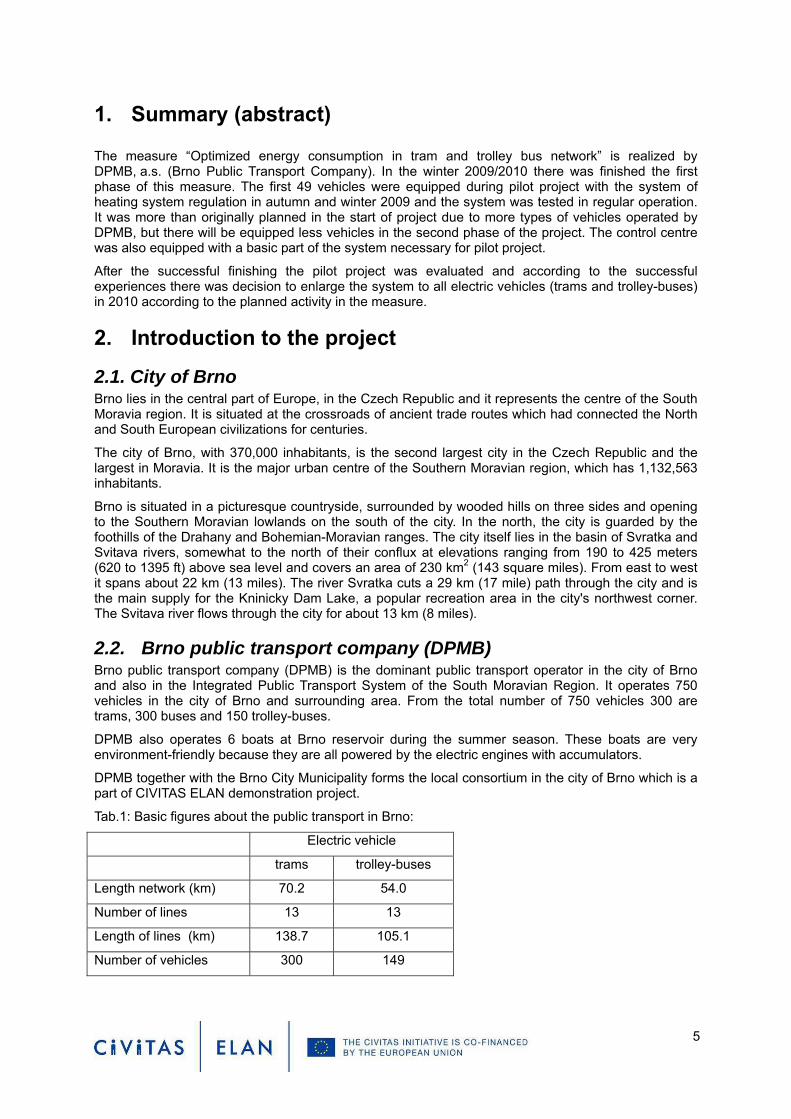
2.2. Brno public transport company (DPMB) Brno public transport company (DPMB) is the dominant public transport operator in the city of Brno and also in the Integrated Public Transport System of the South Moravian Region. It operates 750 vehicles in the city of Brno and surrounding area. From the total number of 750 vehicles 300 are trams, 300 buses and 150 trolley-buses.
DPMB also operates 6 boats at Brno reservoir during the summer season. These boats are very environment-friendly because they are all powered by the electric engines with accumulators.
DPMB together with the Brno City Municipality forms the local consortium in the city of Brno which is a part of CIVITAS ELAN demonstration project.
Tab.1: Basic figures about the public transport in Brno:
Electric vehicle
trams trolley-buses
Length network (km) 70.2 54.0
Number of lines 13 13
Length of lines (km) 138.7 105.1
Number of vehicles 300 149

2.3. Trams and trolley-buses DPMB operated more than 300 trams and 149 trolley-buses on 13 trams and 13 trolley-bus lines in the City of Brno and surrounding areas (Modřice, Šlapanice, Ostopovice). There are many various types of trams and trolley-buses. The oldest vehicles are more than 40 years old.
2.4. Heating system in trams and trolley-buses Because of the geographical conditions of the city of Brno, heating system for the drivers and passengers is a common equipment of the public transport vehicles. The heating system in vehicles is divided into two separate parts: one for driver and one for passenger. According to the internal rules of DPMB, the heating system for passengers is in operation when the outside temperature is under 3°C,
Picture 01: Different types of the trams and trolley-buses
Picture 02: Heating system in trams and trolley-buses and its location
6
7
3. Project of the optimized energy consumption in tram and trolley-bus network
3.1. The system of heating system in trams and trolley-buses before CIVITAS ELAN
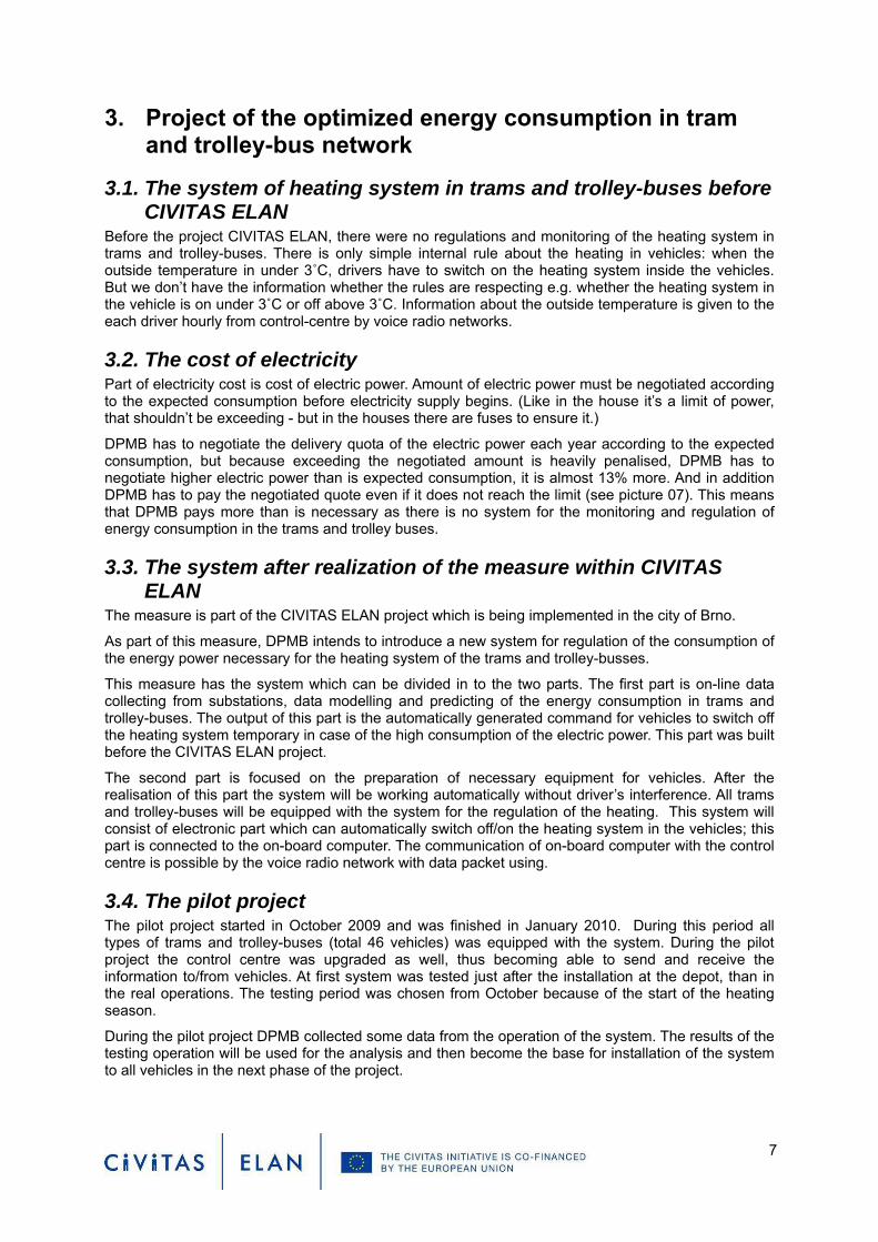
Before the project CIVITAS ELAN, there were no regulations and monitoring of the heating system in trams and trolley-buses. There is only simple internal rule about the heating in vehicles: when the outside temperature in under 3˚C, drivers have to switch on the heating system inside the vehicles. But we don’t have the information whether the rules are respecting e.g. whether the heating system in the vehicle is on under 3˚C or off above 3˚C. Information about the outside temperature is given to the each driver hourly from control-centre by voice radio networks.
3.2. The cost of electricity Part of electricity cost is cost of electric power. Amount of electric power must be negotiated according to the expected consumption before electricity supply begins. (Like in the house it’s a limit of power, that shouldn’t be exceeding - but in the houses there are fuses to ensure it.)
DPMB has to negotiate the delivery quota of the electric power each year according to the expected consumption, but because exceeding the negotiated amount is heavily penalised, DPMB has to negotiate higher electric power than is expected consumption, it is almost 13% more. And in addition DPMB has to pay the negotiated quote even if it does not reach the limit (see picture 07). This means that DPMB pays more than is necessary as there is no system for the monitoring and regulation of energy consumption in the trams and trolley buses.
3.3. The system after realization of the measure within CIVITAS ELAN
The measure is part of the CIVITAS ELAN project which is being implemented in the city of Brno.
As part of this measure, DPMB intends to introduce a new system for regulation of the consumption of the energy power necessary for the heating system of the trams and trolley-busses.
This measure has the system which can be divided in to the two parts. The first part is on-line data collecting from substations, data modelling and predicting of the energy consumption in trams and trolley-buses. The output of this part is the automatically generated command for vehicles to switch off the heating system temporary in case of the high consumption of the electric power. This part was built before the CIVITAS ELAN project.
The second part is focused on the preparation of necessary equipment for vehicles. After the realisation of this part the system will be working automatically without driver’s interference. All trams and trolley-buses will be equipped with the system for the regulation of the heating. This system will consist of electronic part which can automatically switch off/on the heating system in the vehicles; this part is connected to the on-board computer. The communication of on-board computer with the control centre is possible by the voice radio network with data packet using.
3.4. The pilot project The pilot project started in October 2009 and was finished in January 2010. During this period all types of trams and trolley-buses (total 46 vehicles) was equipped with the system. During the pilot project the control centre was upgraded as well, thus becoming able to send and receive the information to/from vehicles. At first system was tested just after the installation at the depot, than in the real operations. The testing period was chosen from October because of the start of the heating season.
During the pilot project DPMB collected some data from the operation of the system. The results of the testing operation will be used for the analysis and then become the base for installation of the system to all vehicles in the next phase of the project.
8
4. Planning We started to plan the project in 2008. During the preparation of the project, we decided to divide the project into the two phases:
1. Pilot project, when all different type of the trams and trolley-buses from DPMB fleet will be equipped with the system; during this first phase it would be possible to test the system and discover possible deficiencies, which can be fixed before second phase will be started;
2. The rest of the trams and trolley-buses will be equipped with the system in the next phase. Within the CIVITAS ELAN project, only the system installed in to the vehicles and the upgrading of the control centre is co-financed from the project budget.
5. Description of the system
5.1. Monitoring and demand management of electricity to the electric traction vehicles
5.1.1. Description of the electric network for trams and trolley-buses Electric power network for DPMB is located in the city of Brno and municipality’s Šlapanice and Modřice. Powering of this extensive network provide substations (see picture 04). Substations are connected to the distribution network of the distribution system of electric energy and they are also equipped with electrometers for measuring power consumption, as well as other eight DPMB buildings. All these measuring points (36 in total) are a sampling site. In one sampling point is traded contemporary values based on the sum of the individual measuring points (substations).
5.2. General description of the project The proposed technical solution will optimize the shape of curve of electricity consumption for electric vehicle traction through continuous monitoring of the collected data from measurement points (electrometers); summarize the overall immediate collection data and evaluation of the trend of electric consumption in the current quarter-hour. On reaching the levels set by contracting reserved capacity in the grid will be sent a command to short-term reduction in heating power in the vehicles. Thus it will be possible to reduce the electric capacity reserved in contract, which must be considered now without the possibility of regulation.
5.3. Monitoring and regulation of consumption power (MROV) The first phase of monitoring and regulation of consumption power (MROV) was implemented in the years 2007-2008, at the same time as the reconstruction of the remote control for substations. This part wasn’t built within the CIVITAS ELAN project, but it was built before the CIVITAS ELAN project as a prerequisite for the further work in the CIVITAS ELAN project
The system MROV consists of:
5.3.1. Collecting and transmitting data to the control centre of MROV Real-time data of electric consumption (impulses from electrometers) are collecting and processing in individual measuring points (see picture 06). The communication link for transferring data to control centre MROV is common with the remote control system for substations.
5.3.2. Processing and evaluation of data at the control centre MROV In the control centre of MROV all collected data are processing. The real situation of the consumption is graphically displayed, including the prediction of electric energy consumption in the current quarter-hour (see picture 05). User operating system is open to special applications, which can be installed and run on any personal computer connected to DPMB computer network. Through this application is also possible to set the parameters that are used in the system for comparing of prediction to limits values from the contractual reserved capacity. The control centre MROV is self-assessment and when is expected of exceeding the limit value, the command is automatically send to the PT vehicles to limit

9
short-term performance of heating system. The command to the vehicle can be also send manually from the control centre.
5.3.3. Output from the control centre MROV The output from the control centre MROV is command (protocol) designed for the use in corporate computer network to the Control and Information system (RIS)3. This command carries information about the time of the request for short-term reduction of the heating power in PT vehicles and information about the required duration of this restriction.
5.4. Utilization Control and Information System (RIS) in MROV
5.4.1. Processing command to limit the heating system RIS Command for short-term restrictions of the heating system in the PT vehicles is processed through RIS server and this server sends the command in data packet format to the PT vehicle.
5.4.2. Monitoring the status of the PT vehicle heating system in RIS system Monitoring the status of heating system is introduced for the following reasons:
- Monitoring of the system behaviour (response to signal to on/off heating)
- An overview of the status of heating system in PT vehicles will enable the direct leading of the control centre to the heating system in PT vehicles into the status which is corresponding with the quality standard in the context of the current outdoor temperature (technical measure for monitoring compliance of internal guidelines on the warming-up of the PT vehicles).
The data packet emitted from the PT vehicle into the RIS system is a single-bit information about the state of heating (1 = heating enabled, 0 = heater off). For this information is used a reserve bit parallel data packet used. RIS system stores the data packet information in the RIS server and the information is processed. Responsible persons (e.g. electro controller, traffic controller) can see on the monitor the status of the individual PT vehicles heater. Status of the heating system is allocated in the data client in following colours:
- Electric vehicle traction, heating on - light purple, - Electric vehicle traction, heating off - dark blue, - Data on buses without heating - grey - Vehicles with no data on the heating - black, grey - The vehicle completely without data - white Information about the status of the heating system of PT vehicles are archived and can be traced and evaluated in the future.
5.5. Electrical Traction Vehicles
5.5.1. Processing of signal for restriction of the heating in electric traction vehicles The PT vehicle receives the command to limit the heating system from the RIS system. Information is processed in on-board computer, where is stored the program and configuration to control and monitoring of the heating system. After evaluation of the obtained command and duration of restrictions, the on-board computer switches off the heating system for passengers for limited time (up to 5 minutes). The driver is informed about this situation on display of the on-board computer.
The restriction of the heating is applied only in the passenger’s parts of the vehicles. The restriction of the system is self-acting, independent on driver. The heating system in the driver’s cabin and especially the heating of the front window of the PT vehicle is not restricted from safety reasons. Module block heater works only on 24 V DC electric parts. From 600 V DC voltages is galvanically separated.
3 RIS – control and information system – more information: www.dpmb.cz
10
5.5.2. Termination of restrictions of the heating in electric traction vehicles After the restriction of the heating finish, on-board computer turns on heater. Not immediately, but after a time equals to N x 3 seconds. Letter “N” stands for the last digit of the registration number of the vehicle, which is entered into the on-board computer. For example: trolley-bus nr. 3212 starts heating again in 6 second – N is 2 (last digit in registration nr. 3212), 2x3 =6. This measure is due to the peak power constraints, which could arise from the heating on all vehicles simultaneously.
5.5.3. Monitoring the state of heating - vehicles Status of the heating system (on / off) is determined from the circuit controlling the switch between the heating on/off and contactor of the heating system. This is connected to the on-board computer. On-board computer sends all information regularly in data packet by voice radio network to the control centre RIS.

Picture 03: The block schema of the system
11

Picture 04: Distribution system of electric energy DPMB - substations
Picture 05: One-quarter graph of an energy consumption and reserved capacity
12
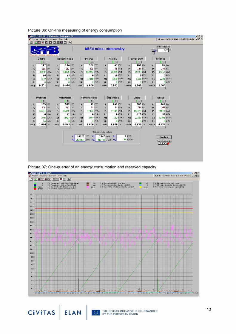
Picture 06: On-line measuring of energy consumption
Picture 07: One-quarter of an energy consumption and reserved capacity
13
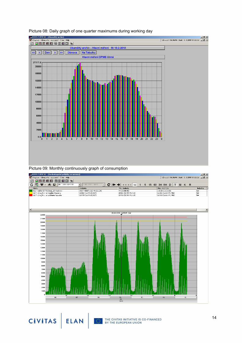
Picture 08: Daily graph of one quarter maximums during working day
Picture 09: Monthly continuously graph of consumption
14

6. Realization
6.1. Plan – Tender conditions After the CIVITAS ELAN contract was successfully signed, requirements for upgrading the system in the control centre and board computer were prepared.
Provider had to fulfil several basic requirements. These were: • Upgrade of on-board computer in vehicles • Upgrade of the control centre – server and software client • On-line data transfer to and from vehicles to the control centre (private radio network), • On-line data transfer inside the vehicle – between the on-board computer and heating system • Archive of commands • Archive of status of the heating system in PT vehicles • The system will be delivered in the two phases. First one includes basic part for upgrading the
control centre and on-board computer necessary for pilot project. After the pilot project, the rest of the equipment will be delivered in the second phase.
The tender was prepared according to the Czech law; it started in November 2009 and was successfully finished in December 2009. The final price of the system was in-line to our expectations.
6.2. Contract for upgrading the control centre and board computer The contract was signed with the company Buse, s.r.o. on 14th December 2009. According to the signed contract, Buse s.r.o. should deliver the system in two phases: the first (basic) part should be done till 31th December 2009. The second (extended) part should be done till 31st March 2010.
The signed contract included upgrading the control centre and board computer in vehicles for new system.
6.3. Implementation to the vehicles New module (see picture 10) for implementation to the trams and trolley-buses was designed in DPMB. It is connection between the on-board computer and heating system and allows:
• to switch on/off the heating system • to communicate with the on-board computer and monitoring the actual condition of heating system
The new module is manufactured in DPMB by DPMB workers. Only standard components are used during the manufacturing process.
Picture 10: Module for heating system, which is implemented to the PT vehicle.
15
16
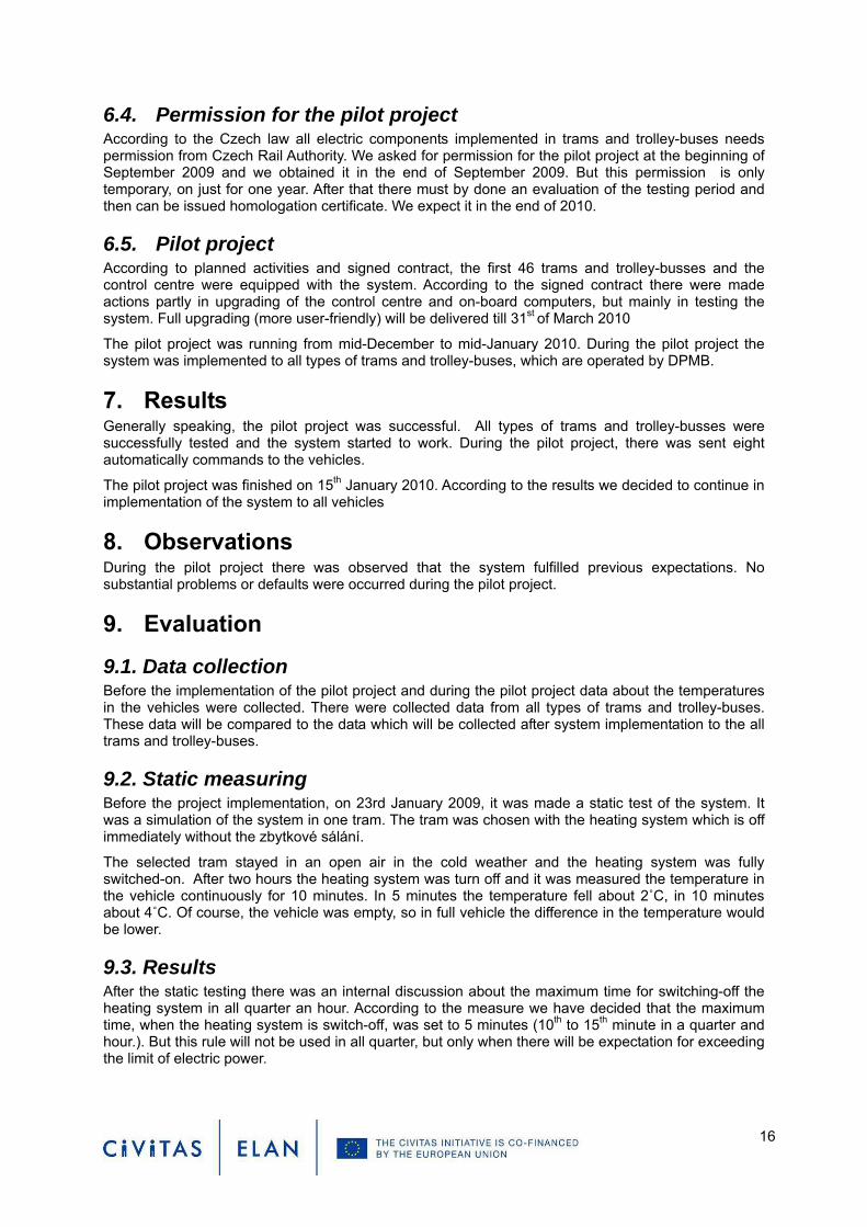
6.4. Permission for the pilot project According to the Czech law all electric components implemented in trams and trolley-buses needs permission from Czech Rail Authority. We asked for permission for the pilot project at the beginning of September 2009 and we obtained it in the end of September 2009. But this permission is only temporary, on just for one year. After that there must by done an evaluation of the testing period and then can be issued homologation certificate. We expect it in the end of 2010.
6.5. Pilot project According to planned activities and signed contract, the first 46 trams and trolley-busses and the control centre were equipped with the system. According to the signed contract there were made actions partly in upgrading of the control centre and on-board computers, but mainly in testing the system. Full upgrading (more user-friendly) will be delivered till 31st of March 2010
The pilot project was running from mid-December to mid-January 2010. During the pilot project the system was implemented to all types of trams and trolley-buses, which are operated by DPMB.
7. Results Generally speaking, the pilot project was successful. All types of trams and trolley-busses were successfully tested and the system started to work. During the pilot project, there was sent eight automatically commands to the vehicles.
The pilot project was finished on 15th January 2010. According to the results we decided to continue in implementation of the system to all vehicles
8. Observations During the pilot project there was observed that the system fulfilled previous expectations. No substantial problems or defaults were occurred during the pilot project.
9. Evaluation
9.1. Data collection Before the implementation of the pilot project and during the pilot project data about the temperatures in the vehicles were collected. There were collected data from all types of trams and trolley-buses. These data will be compared to the data which will be collected after system implementation to the all trams and trolley-buses.
9.2. Static measuring Before the project implementation, on 23rd January 2009, it was made a static test of the system. It was a simulation of the system in one tram. The tram was chosen with the heating system which is off immediately without the zbytkové sálání.
The selected tram stayed in an open air in the cold weather and the heating system was fully switched-on. After two hours the heating system was turn off and it was measured the temperature in the vehicle continuously for 10 minutes. In 5 minutes the temperature fell about 2˚C, in 10 minutes about 4˚C. Of course, the vehicle was empty, so in full vehicle the difference in the temperature would be lower.
9.3. Results After the static testing there was an internal discussion about the maximum time for switching-off the heating system in all quarter an hour. According to the measure we have decided that the maximum time, when the heating system is switch-off, was set to 5 minutes (10th to 15th minute in a quarter and hour.). But this rule will not be used in all quarter, but only when there will be expectation for exceeding the limit of electric power.

17
According to the observation the difference between the temperatures is relatively small and there will be not negative impact for passengers.
The measuring also confirmed that the situation after the implementation should be in-line with the expectations. This presumption will be fully confirmed after implementation of the project to the all vehicles.
10. Dissemination The project was presented in September 2009 during the European Mobility Week at CIVITAS ELAN Information Point in Brno.
On February 23rd 2010 there was a presentation about the measure and the project to the “Scientist-technical club” in Brno (see picture 11). This club is open to all people who are interested in technical issues in the Public Transport.
In February 2010 there was also a meeting with the “Transport club” in their centre in Brno (see picture 12,13). Members of this club are children and young people, who are interested in public transport.
We are preparing a special article about the measure, which will be published in the “Šalina” magazine in the summer 2010. “Šalina” is distributed for free in all tram vehicles. In this magazine the important information about operation of the public transport are provided to the customers.
In the internet pages of DPMB (www.dpmb.cz) there are actual information about the project realisation.
During the European Mobility Week, when the CIVITAS ELAN was presented to public, DPMB was contacted by the PhD student of the Jan Perner Transport Faculty of University of Pardubice. Together with Transport Faculty in Pardubice, DPMB and Brno City Municipality are preparing a lecture on CIVITAS and its measures, especially this one, for students from faculty of transport. This lecture will take place in 2010.

Picture 11: Meeting of Scientist-technical club
Picture 12: Meeting with the transport club
18

Picture 13: Meeting with the transport club
11. Next steps Because the pilot project is considered a success, the rest of PT vehicles will be equipped with the system by the end of the year 2010. According to the signed contract the control centre will be fully upgraded by the end of March 2010.
After the installation of the system to all vehicles, another data collection phase will take place. Collected data will be used for the analysis and evaluation report.
After the installation the system to all vehicles there will be possible to sign new contract for electricity. In the new contract there will be possible to set lower reserved capacity with positive impact to the costs.
19
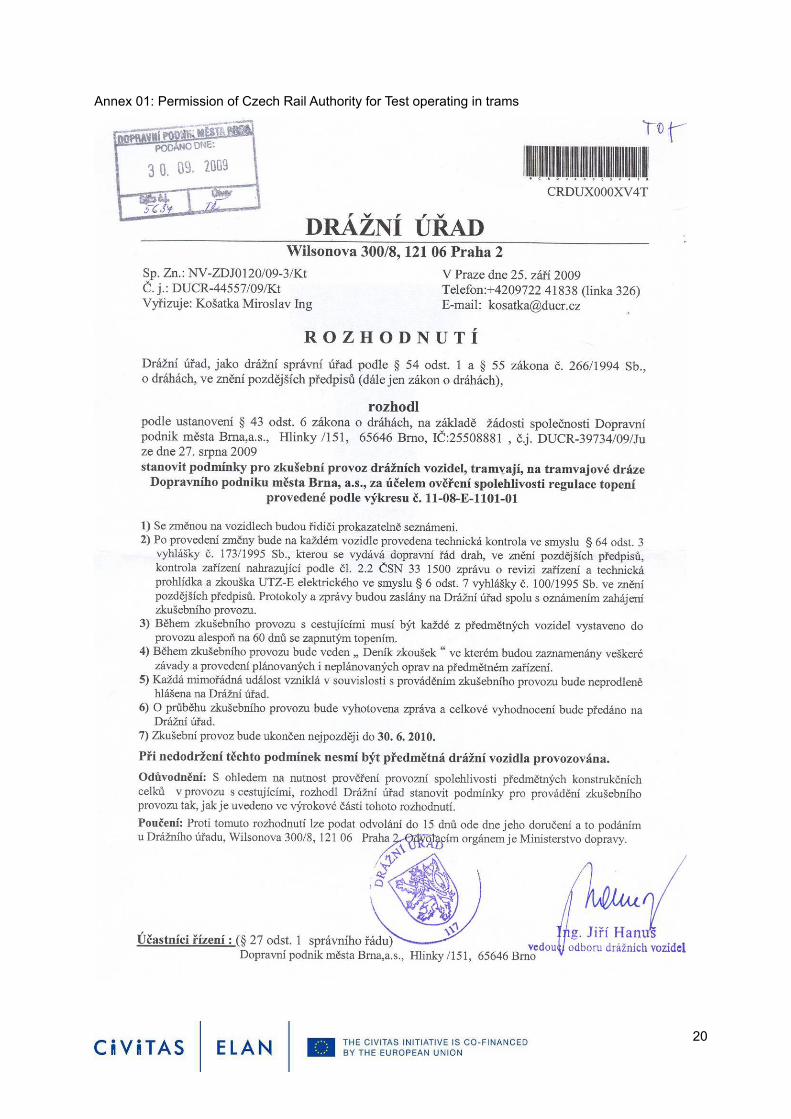
Annex 01: Permission of Czech Rail Authority for Test operating in trams
20
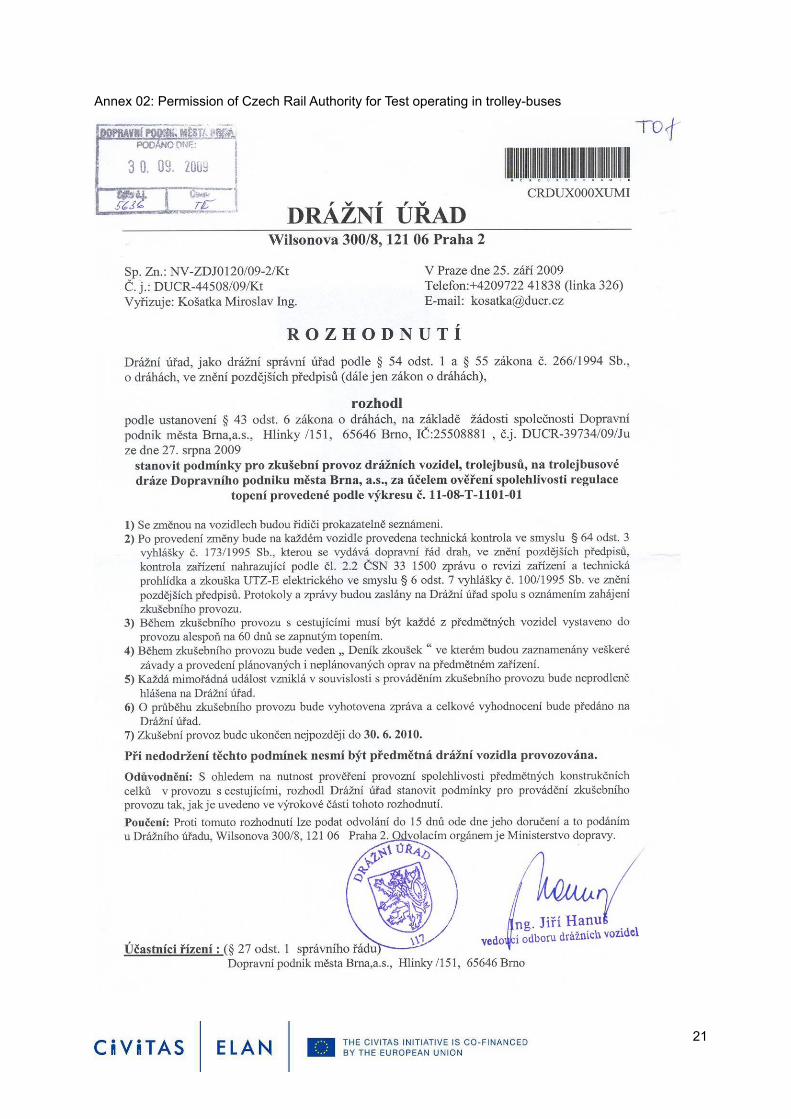
Annex 02: Permission of Czech Rail Authority for Test operating in trolley-buses
21

Annex 03: Scheme of connection in trams
22

Annex 04: Scheme of connection in trolley-buses
23