Embed Size (px)
Citation preview
IMPLEMENTATION OF RIGID PAVEMENT THICKNESS DESIGN FOR NEW PAVEMENTS
By: Izydor Kawa and Edward H. Guo
Galaxy Scientific Corporation 2500 English Creek Ave., Bldg. C
Egg Harbor Twp., NJ 08234-5562, U.S.A. Phone: (609) 645-0900; FAX: (609) 645-2881
[email protected] [email protected]
Gordon F. Hayhoe and David R. Brill
FAA William J. Hughes Technical Center Airport Technology Research and Development Branch, AAR-410
Atlantic City International Airport, NJ 08405, U.S.A. Phone: (609) 485- 8555; FAX: (609) 485-4845
[email protected] [email protected]
PRESENTED FOR THE 2002 FEDERAL AVIATION ADMINISTRATION AIRPORT TECHNOLOGY TRANSFER CONFERENCE
05/02
Kawa 1
ABSTRACT
LEDFAA is a computer program which is based on layered elastic analysis (LEA) and full-scale test data. It has been a part of the U.S. Federal Aviation Administration’s (FAA) Advisory Circular AC 150/5320-16 since 1995. However, one of the limitations of LEDFAA for rigid pavements is the lack of a direct slab edge stress calculation. Slab interior stress is calculated first, then converted into edge stress using transformation functions developed for specific aircraft. The FAA has been working on replacing the indirect slab edge stress calculation in LEDFAA with a direct slab edge stress calculation using a three-dimensional finite element method (3D-FEM). Requirements of the new procedure are that it run on any personal computer, be user-friendly, and be applicable to any gear configuration. The FAA plans to produce a 3D-FEM based design procedure as a new design standard for release in FY 2006. A finite element model of the pavement structure was developed and run with a general-purpose 3D-FEM program (NIKE3D) available in the public domain. NIKE3D and its associated preprocessor program INGRID were originally developed by the Lawrence Livermore National Laboratory, USA. Both programs have been recompiled as dynamic-link libraries and incorporated into LEDFAA. Currently, the project has moved to the stage of implementation of the new modified design procedures incorporating the 3D-FEM model. This paper presents the structure of the new FAA program for pavement thickness design. Example results from the program are presented and compared with results from the existing FAA design procedures. INTRODUCTION AND BACKGROUND
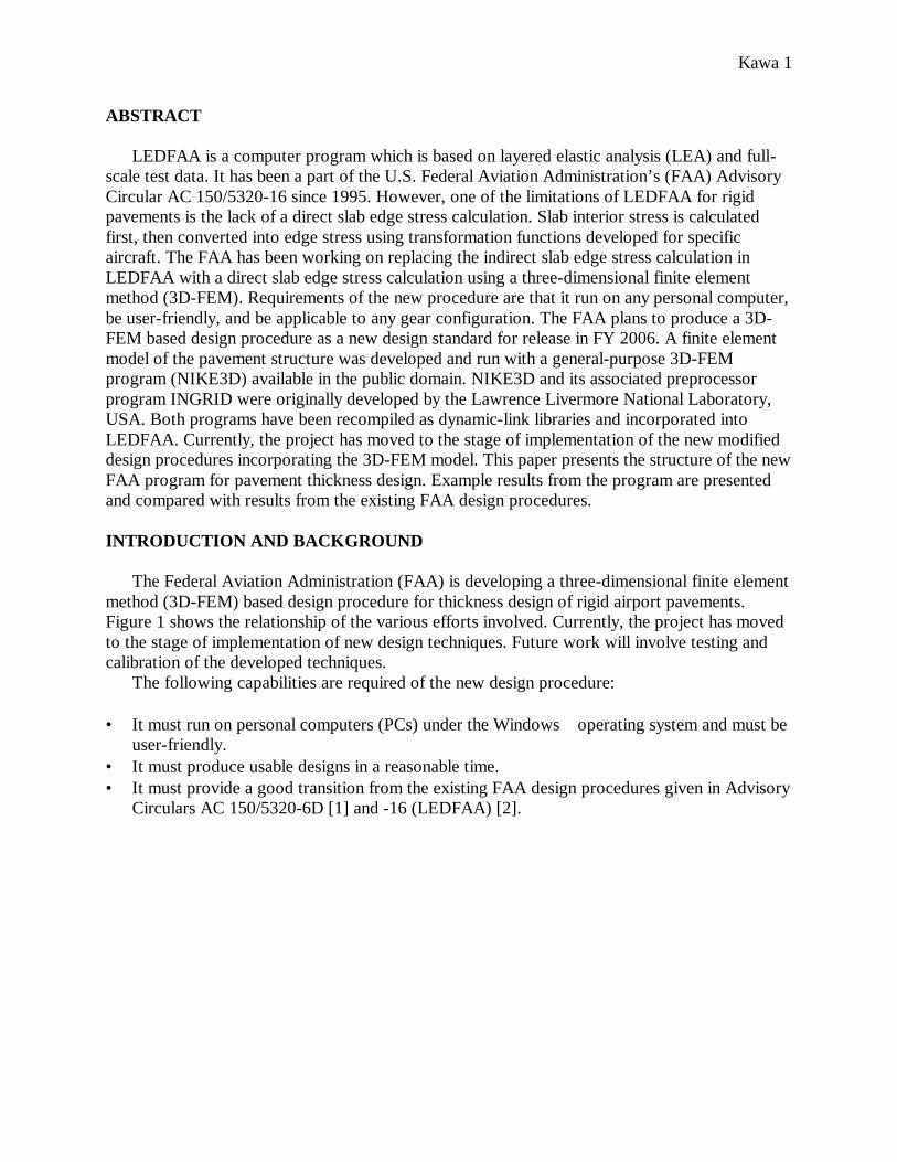
The Federal Aviation Administration (FAA) is developing a three-dimensional finite element method (3D-FEM) based design procedure for thickness design of rigid airport pavements. Figure 1 shows the relationship of the various efforts involved. Currently, the project has moved to the stage of implementation of new design techniques. Future work will involve testing and calibration of the developed techniques.
The following capabilities are required of the new design procedure: • It must run on personal computers (PCs) under the Windows operating system and must be
user-friendly. • It must produce usable designs in a reasonable time. • It must provide a good transition from the existing FAA design procedures given in Advisory
Circulars AC 150/5320-6D [1] and -16 (LEDFAA) [2].
Kawa 2
Figure 1. Development of advanced airport pavement design procedures. MODIFICATION OF LEDFAA
LEDFAA (Layered Elastic Design – FAA) is a computer program developed by the FAA for thickness design of airport pavements. The program was introduced in 1995 as part of FAA Advisory Circular AC 150/5320-16 [2], which governs the design of pavements intended to support aircraft traffic mixes including the Boeing B-777 airplane. The Windows -based LEDFAA program is an outgrowth of the earlier DOS-based LEDNEW computer program developed at the U.S. Army Engineer Waterways Experiment Station (WES) [3]. Like LEDNEW, LEDFAA bases its designs on critical pavement responses (stresses and strains) evaluated using a layered elastic analysis (LEA) of the pavement structure. Critical responses are related to pavement life through empirical failure relations established from analysis of full-scale pavement tests. Mixed traffic is accounted for through the cumulative damage factor (CDF) concept, which is described below.
Computation of rigid pavement response with a layered elastic model has certain limitations. For example, the original LEDNEW design procedure was based on a design factor computed by dividing concrete strength by interior stress [3]. This was modified in the LEDFAA implementation to consider edge stress [4] in order to maintain compatibility with the Westergaard edge stress used in the existing FAA design procedure [1]. In the LEDFAA implementation, the slab edge stress cannot be directly calculated because it is based on the layered elastic model. Instead, slab interior stress is calculated and converted into edge stress
Kawa 3
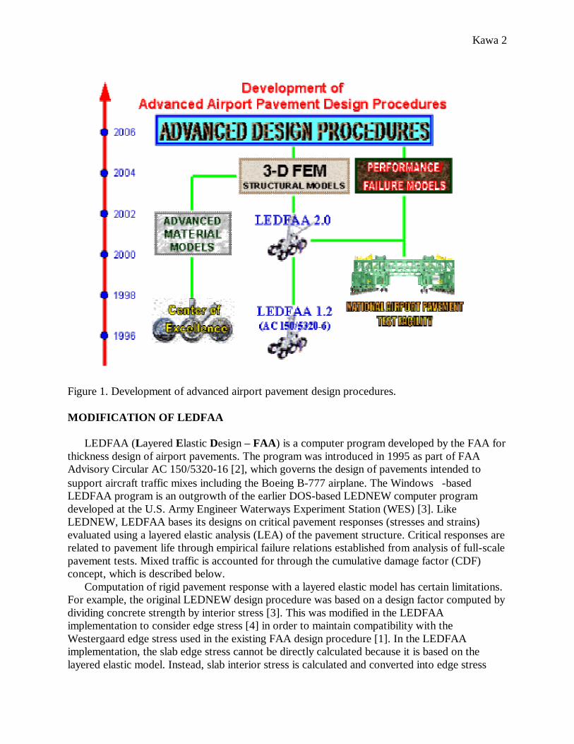
using transformation functions developed for specific aircraft. This is not satisfactory for a long-term solution and the FAA has been working on replacing the indirect edge stress calculation in LEDFAA by a direct edge stress calculation using a 3-D FEM applicable to any gear configuration. A flow chart of the operation of the new FEM based computer program currently under development is presented in figure 2. Depending on the type of pavement thickness design (flexible/rigid and new construction/overlay) being performed, one of four subroutines (DesignFlex, DesignFlexOFlex, DesignRigidOverlay, DesignRigid) drives the CDF computation. As shown in figure 2, the new design procedure retains the LEA analysis for flexible design but calls the 3D-FEM model to compute stresses for rigid pavement design. For rigid design, the block labeled “3D-FEM” computes edge stress directly and replaces the combined layered elastic interior stress computation and transformation from interior stress to edge stress.
The 3D-FEM model was originally developed as a stand-alone application with aircraft and structure data generated through a graphical user interface (GUI) written in Visual Basic [5]. The maximum edge stress was obtained from this program in several steps. First, an automatic mesh generation program (AutoMesh) was called to create intermediate files based on the aircraft and pavement structure parameters selected by the user. Next, the FEM preprocessor, INGRID [6], and the FEM program itself, NIKE3D [7], were called which created output files from which the maximum edge stress was obtained. Figure 2. New LEDFAA program operation.
Aircraft Data Startup Notes
Aircraft Pavement Structure
Subroutine DesignFlex
Subroutine DesignFlexOFlex
Subroutine DesignRigidOverlay
Subroutine DesignRigid
Layered Elastic Analysis LEAF
CDF Computation 3D-FEM
User Interface
Kawa 4
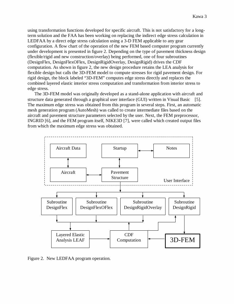
A revised source code for LEDFAA was then written. The revised program executes all the steps required to obtain the maximum edge stress without any user intervention. The automatic mesh generation code (without the GUI) was integrated with LEDFAA and modified so that LEDFAA aircraft and pavement structure inputs are transferred directly to the automatic mesh generation function within LEDFAA. Clicking the Design Structure button (shown in figure 3) executes all the necessary actions from creating input files for INGRID and NIKE3D to obtaining the maximum slab edge stress on the bottom surface of the slab. The calculated NIKE3D stress is then used in conjunction with the existing LEDFAA traffic and failure models to calculate pavement life.
Figure 3. Graphical user interface representing the pavement structure in LEDFAA.
Both LEDFAA and the new FAA 3D-FEM procedure consist of three components: • Structural response model • Traffic model • Failure model
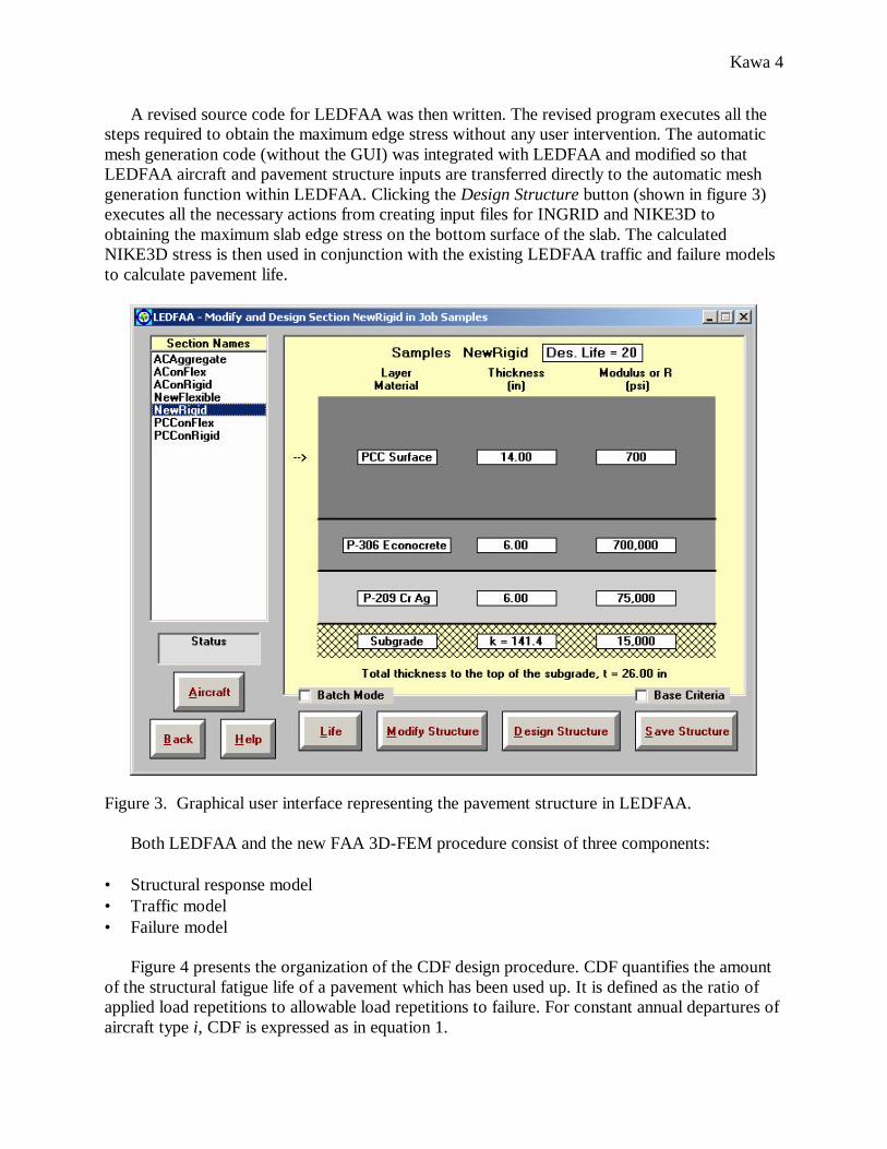
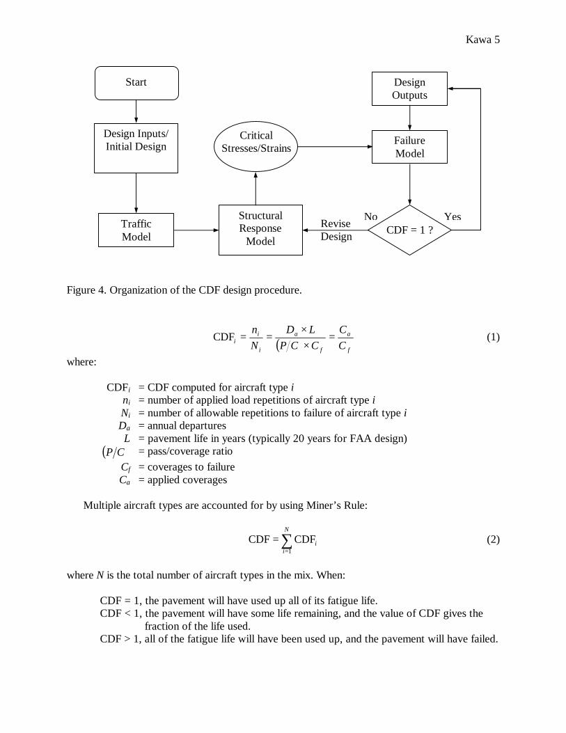
Figure 4 presents the organization of the CDF design procedure. CDF quantifies the amount of the structural fatigue life of a pavement which has been used up. It is defined as the ratio of applied load repetitions to allowable load repetitions to failure. For constant annual departures of aircraft type i, CDF is expressed as in equation 1.
Kawa 5
Figure 4. Organization of the CDF design procedure.
( ) f
a
f
a
i
ii C
CCCPLD
Nn =
××==CDF (1)
where:
CDFi = CDF computed for aircraft type i ni = number of applied load repetitions of aircraft type i Ni = number of allowable repetitions to failure of aircraft type i Da = annual departures L = pavement life in years (typically 20 years for FAA design)
( )CP = pass/coverage ratio Cf = coverages to failure Ca = applied coverages
Multiple aircraft types are accounted for by using Miner’s Rule:
∑=
=N
ii
1
CDF CDF (2)
where N is the total number of aircraft types in the mix. When:
CDF = 1, the pavement will have used up all of its fatigue life. CDF < 1, the pavement will have some life remaining, and the value of CDF gives the
fraction of the life used. CDF > 1, all of the fatigue life will have been used up, and the pavement will have failed.
Start
Design Inputs/ Initial Design
Traffic Model
Design Outputs
Failure Model
Critical Stresses/Strains
Structural Response
Model CDF = 1 ? Revise
Design
No Yes
Kawa 6
In order to apply equations (1) and (2), the variable Cf must be defined in the failure model. The failure model relates a particular structural response variable to the number of load applications associated with structural fatigue failure. In the case of rigid pavements, the response variable used as the failure indicator is the maximum bending stress on the bottom plane of the PCC slab. In the new rigid pavement design procedure, the free edge stress is computed using the 3D-FEM model and substituted directly into the existing CDF design procedure. The following section describes the technical changes that were made to the original stand-alone 3D-FEM model to enable it to be integrated into the LEDFAA design program structure. ADAPTING THE 3D-FEM OPEN SOURCE CODE
The 3D FEM of the pavement structure was developed from the public domain programs INGRID and NIKE3D (version 3.3.2). INGRID and NIKE3D are written in Fortran 77 and were developed originally by the Lawrence Livermore National Laboratory (LLNL), USA. The LLNL programs were developed for use on a variety of specialized platforms, including vectorizing supercomputers and Unix workstations. Both of these programs were migrated to Microsoft Windows -based personal computers by the FAA for further development.
INGRID is a versatile 3-D finite element mesh generator for modeling linear and nonlinear systems. INGRID provides the capability to generate complex geometrical models using beam, shell and hexahedral elements. It also provides the capability to specify boundary conditions, initial conditions, and material properties for complex regions [6]. NIKE3D is a fully implicit 3-D FEM code for analyzing the static and dynamic responses of elastic and inelastic solids, shells, and beams [7]. Since INGRID and NIKE3D are general-purpose programs, they include many procedures that are not needed for the problem of interest, which is the static, linear elastic analysis of pavement structures. To determine which subroutines in INGRID and NIKE3D are needed and which are redundant, all subroutines in both programs were modified so that when any subroutine is called during INGRID or NIKE3D execution, its name is written to an output file. Originally, the NIKE3D source code consisted of 1045 files, and the INGRID source code consisted of 792 files. After identifying the unused subroutines, the NIKE3D source code was reduced to 233 files and the INGRID source code to 256 files.
Originally, INGRID and NIKE3D were compiled for PCs as stand-alone executable (*.exe) files. Using the Compaq Visual Fortran programming environment, both programs were recompiled as Fortran dynamic link libraries (DLLs) and then fully integrated with the main LEDFAA calling program written in Visual Basic version 6. Thus, the design program involves mixed-language programming. The interactions between Visual Basic and Fortran may result in unexpected behavior. For example, in order to determine the final concrete design thickness, the main program calls the INGRID/NIKE3D DLL sequence multiple times as part of an iterative loop (figure 4). However, it was found that when the Visual Basic application (LEDFAA) calls a Fortran DLL, the global DLL variables retain their values after the first run. These variables may be the source of run-time errors when the Fortran DLL is called a second or subsequent times. To correct this condition, code was added to both INGRID and NIKE3D so that all global variables are reinitialized at the end of each DLL call. Thus, multiple calls to the 3D-FEM response module can be made without causing run time errors.
Kawa 7
ADAPTING THE 3D-FEM ANALYSIS MODEL
A nine-slab model was developed previously [5, 8] for analysis of rigid pavement structural response. However, it is not practical at the present time to incorporate this model into the design procedure because run times are excessive. Therefore, a simplified single-slab model has been developed from the nine-slab model for implementation as the response model in the rigid pavement design procedure. Load transfer at the joints will be represented in the design procedure as a reduction in the computed edge stress as is currently done in the Westergaard and LEA based procedures [1, 2]. Improvements in the 3D-FEM model (e.g., multiple slabs, 3D-FEM representation of joints) will be considered if run times can be improved to the point where the improved models become practical.
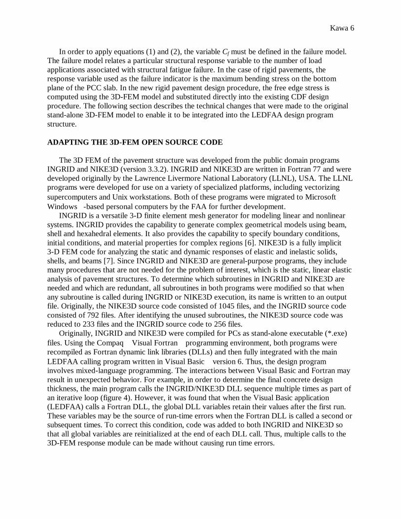
The slab in the 3D-FEM model is considered to be in full contact with the base layer. The interface between the slab and base course is fully unbonded, while all other horizontal interfaces are treated as fully bonded. The 3D-FEM model implements full 3D discretization of base, subbase, and subgrade layers. This approach allows all layers to be modeled using elastic constants E and µ and avoids the necessity of defining a modulus of subgrade reaction k for the foundation. To further reduce the size of the model, “infinite” elements are used to model the far fields in the subgrade layer.
Figure 5 is an example of a 3D-FEM computation showing the horizontal stress on the bottom of the Portland cement concrete (PCC) slab due to a single-wheel load acting on the edge of the slab. For clarity, the entire slab has been shown along with the supporting layers. In the 3D-FEM analysis only one-half of the total finite element domain was modeled, taking advantage of symmetry on the x-z plane.
Kawa 8
X Y
Z
"A"
"A"
350 450400
300250200
150100
50
Figure 5. Horizontal stress at the bottom of the PCC slab due to single wheel free edge load. STRESS CALCULATION TIME
As an airport pavement design tool, LEDFAA must perform thickness design calculations in a reasonable amount of time. Therefore, a major focus of the current research effort is on reducing run time for stress calculations by NIKE3D. Both the complexity of the analyzed pavement structural model and the computer hardware have significant impacts on computation time.
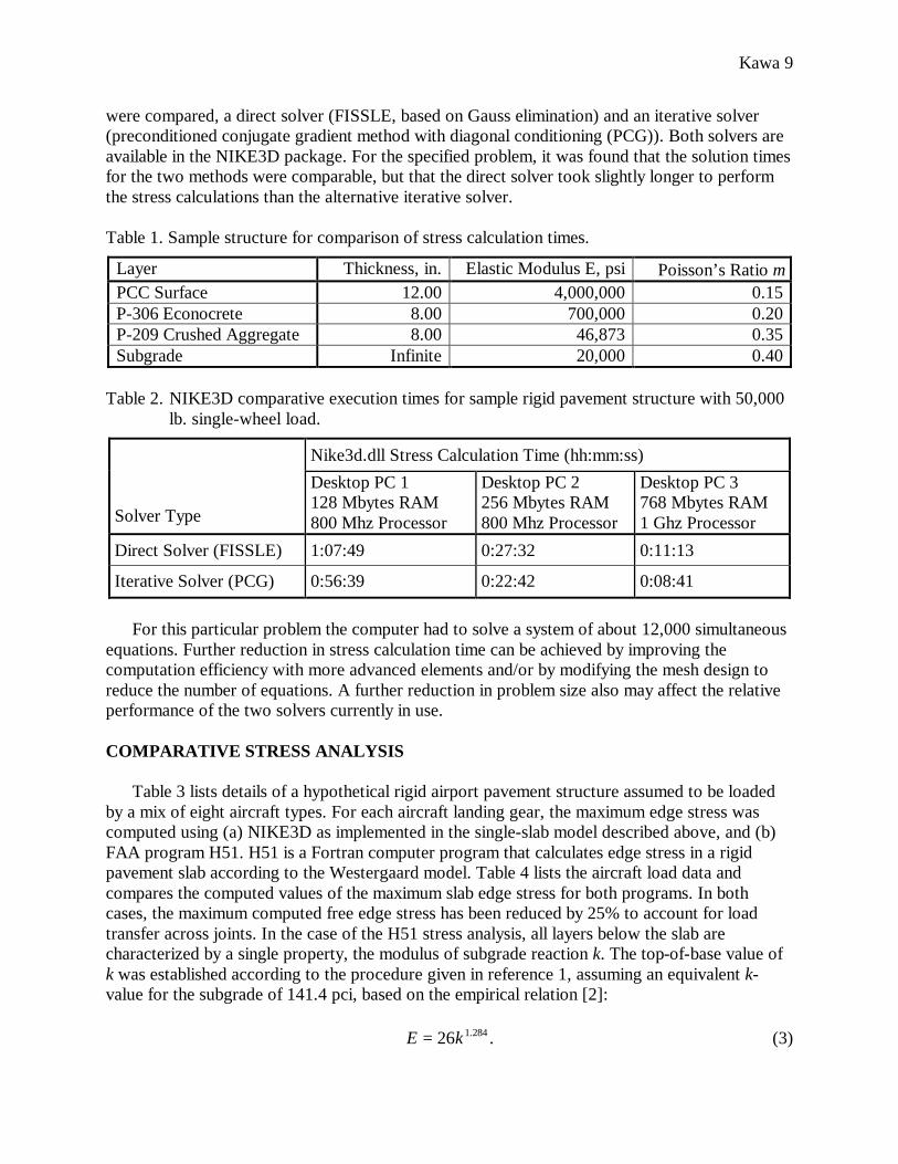
Table 1 lists the layer properties for a sample rigid pavement structure loaded by a 50,000-lb. single wheel. The wheel load is located midway along the slab edge and oriented perpendicular to the edge. The elastic modulus of the crushed aggregate (P-209) layer was calculated automatically by LEDFAA, following the MODULUS procedure originally developed by WES for the LEDNEW program [3]. Table 2 lists real-time requirements on various computers to calculate the slab edge stress using the DLL version of NIKE3D (Nike3d.dll) described above. It can be concluded from table 2 that, for the current program and computer configuration, one of the effective ways of decreasing the stress calculation time is by increasing the size of the computer’s random access memory (RAM). The stress calculation, which takes approximately 1 hour on a desktop computer with 128 Mbytes RAM, can be accomplished in only 10 minutes on a computer with 768 Mbytes of RAM. Two methods of solving the system of linear equations
Kawa 9
were compared, a direct solver (FISSLE, based on Gauss elimination) and an iterative solver (preconditioned conjugate gradient method with diagonal conditioning (PCG)). Both solvers are available in the NIKE3D package. For the specified problem, it was found that the solution times for the two methods were comparable, but that the direct solver took slightly longer to perform the stress calculations than the alternative iterative solver. Table 1. Sample structure for comparison of stress calculation times.
Layer Thickness, in. Elastic Modulus E, psi Poisson’s Ratio µ PCC Surface 12.00 4,000,000 0.15 P-306 Econocrete 8.00 700,000 0.20 P-209 Crushed Aggregate 8.00 46,873 0.35 Subgrade Infinite 20,000 0.40
Table 2. NIKE3D comparative execution times for sample rigid pavement structure with 50,000
lb. single-wheel load.
Nike3d.dll Stress Calculation Time (hh:mm:ss) Solver Type
Desktop PC 1 128 Mbytes RAM 800 Mhz Processor
Desktop PC 2 256 Mbytes RAM 800 Mhz Processor
Desktop PC 3 768 Mbytes RAM 1 Ghz Processor
Direct Solver (FISSLE) 1:07:49 0:27:32 0:11:13
Iterative Solver (PCG) 0:56:39 0:22:42 0:08:41
For this particular problem the computer had to solve a system of about 12,000 simultaneous
equations. Further reduction in stress calculation time can be achieved by improving the computation efficiency with more advanced elements and/or by modifying the mesh design to reduce the number of equations. A further reduction in problem size also may affect the relative performance of the two solvers currently in use. COMPARATIVE STRESS ANALYSIS
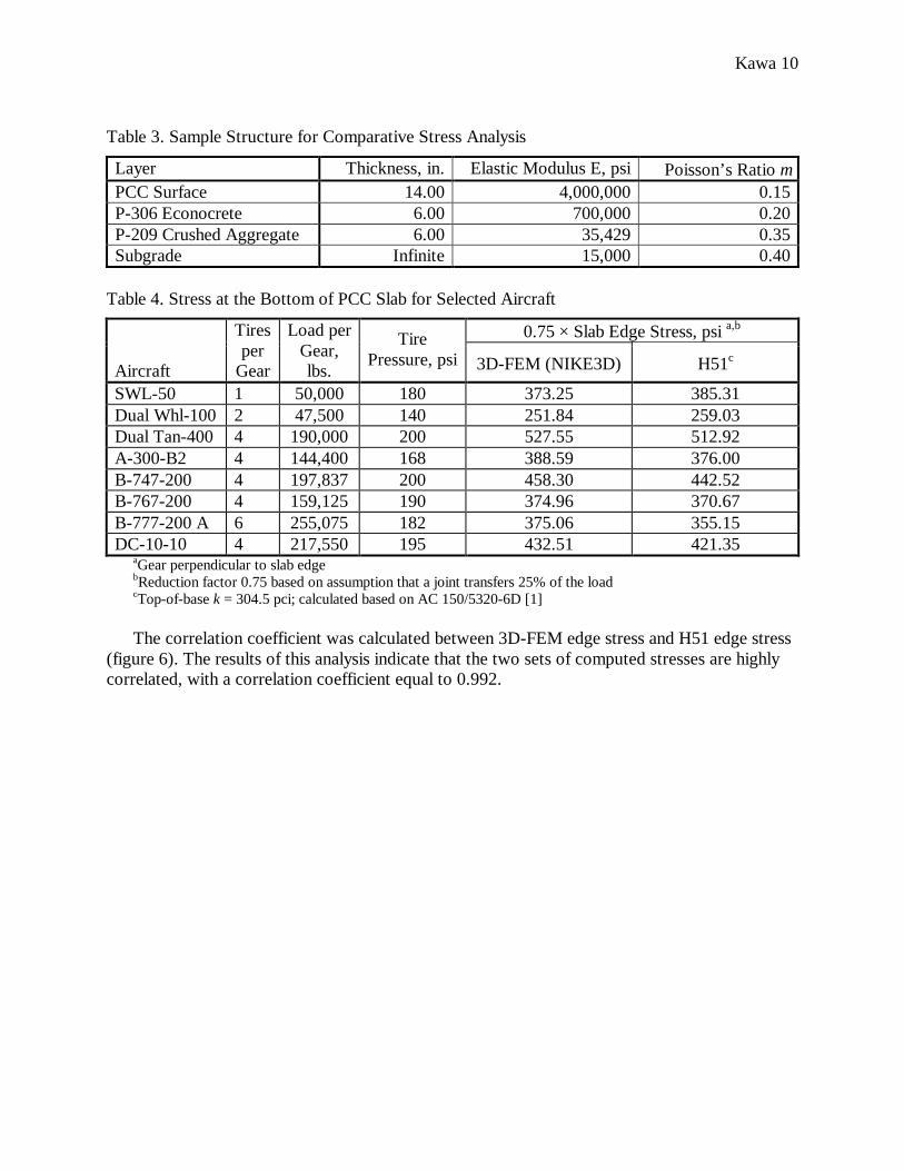
Table 3 lists details of a hypothetical rigid airport pavement structure assumed to be loaded by a mix of eight aircraft types. For each aircraft landing gear, the maximum edge stress was computed using (a) NIKE3D as implemented in the single-slab model described above, and (b) FAA program H51. H51 is a Fortran computer program that calculates edge stress in a rigid pavement slab according to the Westergaard model. Table 4 lists the aircraft load data and compares the computed values of the maximum slab edge stress for both programs. In both cases, the maximum computed free edge stress has been reduced by 25% to account for load transfer across joints. In the case of the H51 stress analysis, all layers below the slab are characterized by a single property, the modulus of subgrade reaction k. The top-of-base value of k was established according to the procedure given in reference 1, assuming an equivalent k-value for the subgrade of 141.4 pci, based on the empirical relation [2]: .26 284.1kE = (3)
Kawa 10
Table 3. Sample Structure for Comparative Stress Analysis
Layer Thickness, in. Elastic Modulus E, psi Poisson’s Ratio µ PCC Surface 14.00 4,000,000 0.15 P-306 Econocrete 6.00 700,000 0.20 P-209 Crushed Aggregate 6.00 35,429 0.35 Subgrade Infinite 15,000 0.40
Table 4. Stress at the Bottom of PCC Slab for Selected Aircraft
0.75 × Slab Edge Stress, psi a,b Aircraft
Tires per
Gear
Load per Gear, lbs.
Tire Pressure, psi 3D-FEM (NIKE3D) H51c
SWL-50 1 50,000 180 373.25 385.31 Dual Whl-100 2 47,500 140 251.84 259.03 Dual Tan-400 4 190,000 200 527.55 512.92 A-300-B2 4 144,400 168 388.59 376.00 B-747-200 4 197,837 200 458.30 442.52 B-767-200 4 159,125 190 374.96 370.67 B-777-200 A 6 255,075 182 375.06 355.15 DC-10-10 4 217,550 195 432.51 421.35
aGear perpendicular to slab edge bReduction factor 0.75 based on assumption that a joint transfers 25% of the load cTop-of-base k = 304.5 pci; calculated based on AC 150/5320-6D [1]
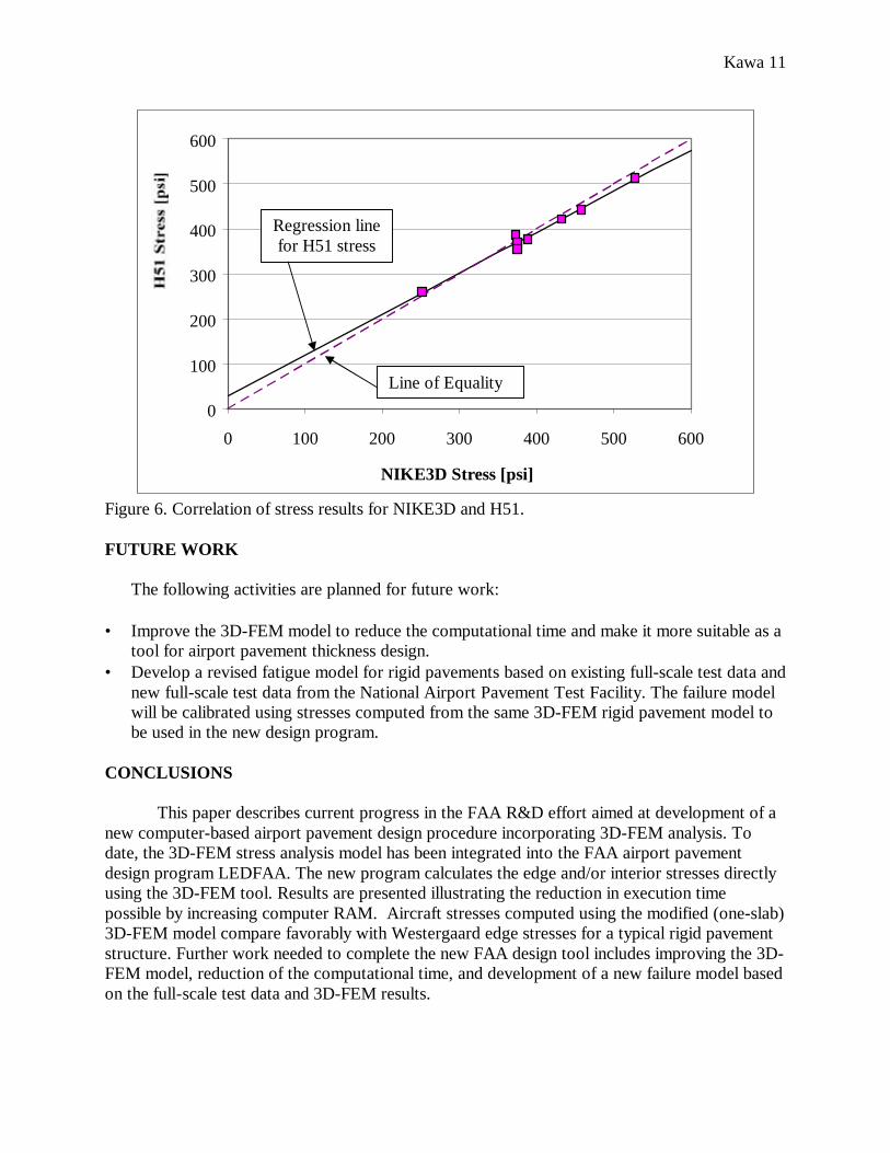
The correlation coefficient was calculated between 3D-FEM edge stress and H51 edge stress
(figure 6). The results of this analysis indicate that the two sets of computed stresses are highly correlated, with a correlation coefficient equal to 0.992.
Kawa 11
0
100
200
300
400
500
600
0 100 200 300 400 500 600
NIKE3D Stress [psi]
Figure 6. Correlation of stress results for NIKE3D and H51. FUTURE WORK
The following activities are planned for future work: • Improve the 3D-FEM model to reduce the computational time and make it more suitable as a
tool for airport pavement thickness design. • Develop a revised fatigue model for rigid pavements based on existing full-scale test data and
new full-scale test data from the National Airport Pavement Test Facility. The failure model will be calibrated using stresses computed from the same 3D-FEM rigid pavement model to be used in the new design program.
CONCLUSIONS
This paper describes current progress in the FAA R&D effort aimed at development of a new computer-based airport pavement design procedure incorporating 3D-FEM analysis. To date, the 3D-FEM stress analysis model has been integrated into the FAA airport pavement design program LEDFAA. The new program calculates the edge and/or interior stresses directly using the 3D-FEM tool. Results are presented illustrating the reduction in execution time possible by increasing computer RAM. Aircraft stresses computed using the modified (one-slab) 3D-FEM model compare favorably with Westergaard edge stresses for a typical rigid pavement structure. Further work needed to complete the new FAA design tool includes improving the 3D-FEM model, reduction of the computational time, and development of a new failure model based on the full-scale test data and 3D-FEM results.
Regression line for H51 stress
Line of Equality
Kawa 12
ACKNOWLEDGEMENTS/DISCLAIMER
The work described in this paper was supported by the FAA Airport Technology R&D Branch, Dr. Satish K. Agrawal, Manager. The contents of the paper reflect the views of the authors, who are responsible for the facts and accuracy of the data presented within. The contents do not necessarily reflect the official views and policies of the FAA. The paper does not constitute a standard, specification, or regulation. REFERENCES 1. Federal Aviation Administration, Office of Airport Safety and Standards, “Airport Pavement
Design and Evaluation,” Advisory Circular AC 150/5320-6D, 1995. 2. Federal Aviation Administration, Office of Airport Safety and Standards, “Airport Pavement
Design for the Boeing 777 Airplane,” Advisory Circular AC 150/5320-16, 1995. 3. Barker, W.R. and C.R. Gonzales, “Pavement Design by Elastic Layer Theory,”
Aircraft/Pavement Interaction: An Integrated System, Proceedings of the Airfield Pavement Specialty Conference, Kansas City, MO, Sept. 4-6, 1991, ASCE, Editor Paul T. Foxworthy, pp. 21-43.
4. Hayhoe, G.F., R.D. McQueen, E.H. Guo, and D.R. Brill, “LEDFAA: The FAA’s New Software for Airport Pavement Design,” U.S. Department of Transportation, Federal Aviation Administration, Office of Aviation Research, Washington, DC, in preparation.
5. Brill, D.R., G.F. Hayhoe, and X. Lee, “Three-Dimensional Finite Element Modeling of Rigid Pavement Structures,” Aircraft/Pavement Technology in the Midst of Change, Proceedings of the 1997 Airfield Pavement Conference, Seattle, Washington, August, 1997, ASCE, Editor Frank V. Herman, pp. 151-165.
6. Stillman, D.W., J.O. Hallquist, and R.B. Ransberger, “INGRID A 3-D Mesh Generator for Modeling Nonlinear Systems User Manual,” Lawrence Livermore National Laboratory, Report UCRL-MA-109790, September 1992.
7. Maker, B.N., R.M. Ferencz, and J.O. Hallquist, “NIKE3D a Nonlinear, Implicit, Three-Dimensional Finite Element Code for Solid and Structural Mechanics User Manual,” Lawrence Livermore National Laboratory, Report UCRL-MA-105268, November 1990.
8. Brill, D.R., “Field Verification of a 3D Finite Element Rigid Airport Pavement Model,” Report No. DOT/FAA/AR-00/33, U.S. Department of Transportation, Federal Aviation Administration, Office of Aviation Research, Washington, DC, July 2000.