Embed Size (px)
Citation preview

International Research Journal of Engineering and Technology (IRJET) e-ISSN: 2395-0056
Volume: 04 Issue: 07 | July -2017 www.irjet.net p-ISSN: 2395-0072
© 2017, IRJET | Impact Factor value: 5.181 | ISO 9001:2008 Certified Journal | Page 708
Implementation and Validation of K Line (ISO 9141) Protocol for Diagnostic Application
Gauri Mahajan1, Mr. S.K.Parchandekar2, Mr. Mohammad Tahir3
1,2 Department of Electronics Engineering Walchand college of Engineering, Sangli, Maharashtra, India
3 Project Manager , Tata Consultancy Services, Pune, Maharashtra, India --------------------------------------------------------------------------***-----------------------------------------------------------------------
Abstract: There is requirement for setting up the interchange of digital information between on-board emission-related Electronic Control Units (ECUs) of road vehicles and the SAE OBD II scan tool as specified in SAE J1978. This communication is established in order to facilitate inspection, test diagnosis and adjustment of vehicle systems and ECUs. OBD II uses various protocols, of which K line is mainly used for diagnostics purpose. K line Transmission is based on UART signaling and Communication uses Request Response Pattern. This protocol is in use but components used to design K line transceiver have become absolute these days. So there is need to come up with new solution for K line transceiver which will satisfy all existing requirements and have life of at least 10 years ahead. Keywords: K-Line, On Board Diagnostic (OBD), L-Line
I.INTRODUCTION
On Board Diagnostic II:
The solution to reduce emissions is development of
good testing system of vehicles. On Board Diagnostic (OBD) is a system, introduced by the ―California Air Resources Board‖. OBD systems are incorporated in computers to monitor vehicles components which may affect emissions when they are malfunctioning. OBD systems provide access to users to monitor various key components of vehicle. These systems always detect malfunction. The OBDII (On-Board Diagnostics II) system ensures correct operation of the vehicle’s emission control system during its lifetime by monitoring components for deterioration and malfunction. The output of the OBD system is malfunction indicator lamp (MIL), also known as “check engine” lamp. When fault is detected, MIL is illuminated and diagnostic trouble code (DTC) is stored. A freeze frame, containing diagnostic data taken from that moment, is also stored. A diagnostic tester (scan tool) is required to obtain and display the diagnostic information stored via serial diagnostic
interface. The information can be read using one of the following 4 legislated data link layer protocols:
SAE J1850 (ISO 11519-4) ISO 9141-2(K-Line)
ISO 14230-4 (KWP 2000 – Keyword Protocol) ISO 15765-4 (CAN Diagnostics) K Line:
The K-Line is suitable for both on-board and off-
board diagnostics. K-Line is a bidirectional line. It is used during initialization to convey address information from the diagnostic tester to vehicle ECUs, simultaneously with the line-L. Line-L is a unidirectional line and used only during initialization to convey address information from the diagnostic tester to vehicle ECUs, simultaneously with the K line. At all other times it should remain idle in the logic “1” state. After conveying the address, the K line is used to convey bidirectional data between vehicle ECUs and the diagnostic tester to complete initialization. After initialization, it is used to convey request messages from the diagnostic tester to vehicle ECUs and response messages from the vehicle ECUs to the diagnostic tester. Specifications:
1. Specifies Physical and Link layers 2. Bidirectional bus, communicating over 1 wire (the K
Line)

International Research Journal of Engineering and Technology (IRJET) e-ISSN: 2395-0056
Volume: 04 Issue: 07 | July -2017 www.irjet.net p-ISSN: 2395-0072
© 2017, IRJET | Impact Factor value: 5.181 | ISO 9001:2008 Certified Journal | Page 709
3. Optional: additional unidirectional L Line (Allows mixed networks using only K Line / using both K+L Line)
4. Bit transmission compatible to UART (Universal Asynchronous Receiver Transmitter): 1 start bit, 8 data bits, 1 stop bit, optional parity bit.
5. Bit rate: 10.4 Kbit/s. CONNECTION ESTABLISHMENT PROTOCOL (2 VARIANTS) 5 BAUD INITIALIZATION: Figure below shows inter-byte and inter-message timing parameters and explains 5 baud initialization. The total time for address lasts for 2 seconds. After validation of address internally in vehicle ECU(s), which takes time known as W1, which is between 60 to 300 ms long, vehicle will respond with synchronization byte 55H informing tester of new baud rate of 10.4 Kbps. The vehicle shall then wait a time known as W2, which is between 5 to 20 ms, for tester to reconfigure to new baud rate, and then the vehicle will send two key bytes.
Fig: 5 Baud Initialization These key bytes shall be either 08 08 or 94 94, separated by time W3,which is between 0 to 20 ms, that describe tester the value of P2MIN(time period between completion of stop bit of last byte of message and first edge of start bit of next message). Message can be request or response or multiple vehicle response. If message synchronization is achieved only by timing then P2 MIN shall be 25 ms and keywords 08 08 shall be used. If another type of message synchronization is provided then P2MIN shall be 0 ms and keywords 94 94 shall be used. As an acknowledgment of reception of key bytes, the tester, after waiting for time period W4, which is between 25 to 50 ms, shall then invert key byte #2 and send it to the vehicle. After waiting for another period W4, the vehicle shall then invert initialization address of 33 and send it to tester as
“ready to communicate” signal. This ends initialization sequence.
Fig: Signal voltage levels, worst case values
Signaling: ECU and tester shall properly determine each logic state 1) Logic “0”: is equivalent to a voltage level on the line of less than 20 % VB, for transmitter, 30 % VB, for receiver. 2) Logic “1”: is equivalent to a voltage level on the line of greater than 80 % VB for transmitter, 70 %VB for receiver. In addition, the slope times shall be less than 10 % of the bit time. II. Brief Review of Literature Survey: 1) ISO 9141-2-1994 : It specifies the requirements for setting up the interchange of digital information between on-board emission-related Electronic Control Units (ECUs) of road vehicles and the SAE OBD II scan tool as specified in SAE J1978.This paper also describes signaling ,frame format ,way of communication, message structure, requirements of diagnostic tester ,requirements of ECU. 2) ISO 9141-2-1989: It specifies various system configurations that can be made by using K Line and L Line. The capacitance contribution by various element and baud rate limitation is also explained in this paper. III. Validation of K line transceiver: Drawback of old transceiver: There is no as such flaw of old transceiver but it is obsolete that’s why there is need to change transceiver.
While selecting new transceiver solution for
diagnostic purpose there are various areas need to be focused which are given below:

International Research Journal of Engineering and Technology (IRJET) e-ISSN: 2395-0056
Volume: 04 Issue: 07 | July -2017 www.irjet.net p-ISSN: 2395-0072
© 2017, IRJET | Impact Factor value: 5.181 | ISO 9001:2008 Certified Journal | Page 710
1) Whether new solution is ISO 9141 supported or not. Data rate, voltage level compatibility, supply voltage, supply current, operating temperature, cost.
2) Point need to be considered for validation: Amplitude, rise time, fall time, baud rate. 3) Parameters taken into consideration while choosing new transceiver: Important point needs to be considered is a package type. The package type should be such that you need not require changing whole design.
4) Another point is whether transceiver is AEC qualified or not (Automotive supported or not).AEC (Automotive Electronics Council) is organization based on US that sets qualification standard for supply of components ion automotive industry. This standard check if life time of component passes required benchmark. It also checks temperature, moisture resistance of component from minimum to maximum reading. Depending on these parameter we have compared available choices for K Line transceiver and we selected the best choice i.e. TJA1020. TJA1020 is LIN transceiver which is having compatibility with K line. So this transceiver is selected for this application. Input levels of TJA1020 are compatible with 3.3 V and 5 V devices. It supports Baud rate up to 20 Kbaud. It has passive behavior in unpowered state. Then we compared the parameter of new transceiver with old one. Parameter matches almost except fall time but it don’t have adverse effect on the functionality of K-line protocol. IV. Communication Flow Host will transmit request over USB. USB will pass this request to request handler. According to module ID request handler will forward the request to corresponding module. In our case the request will be forwarded to K Line, it will transmit this request to ECU. The Request handler task is ID,
Fig: Communication Flow
It is the job of responsible for routing the requests to the appropriate module. In case, the request contains an invalid module the request handler to indicate the error to the
HOST. Depending on request received ECU will perform some action and will transmit response, which will transmit back to Host through K line, response handler, USB. This will be flow of communication between Host and ECU.
To deal with real time environment it is essential to choose RTOS (Real time Operating system).The whole implementation is divided into following two parts,
1) Hardware design to implement K line 2) Firmware design to establish communication
with host.
V. Firmware System Design The main function of firmware is to act like middle layer for data transmission between host and K-Line protocol device. a) Vxworks RTOS: To deal with real time environment it is essential to choose RTOS (Real time Operating system). This project contains three parts i.e. application, I/O system and Kline driver. Application part which consist of number of API such as start communication, set parameters, build response, build acknowledgement. So there are number of events, interrupts, requests. To handle all this semaphore, message queue, events are required. So there is need of RTOS. In this project Vxworks RTOS is used. VxWorks is a real-time operating system. It is developed as proprietary software by Wind River Systems. The key features of Vxworks are high performance, scalable RTOS. It supports ARM, Pentium, Intel X-Scale, Super H and other popular processors for embedded system design. Fast execution of application codes is possible because Vxworks supports kernel mode execution of tasks. Support of powerful development tools that make Vxworks easy and efficient to use. Many simulation tools, time-performance analysis tools, debug and test tools are provided, which makes VxWorks as an RTOS that supports development of almost any embedded application. b) Firmware Flow: If host want to send any parameter to ECU then first frame is formed in application then it is send to I/O routine .I/O routine call basic write call and send data to Kline driver routine. Finally driver routine sends that data to Kline bus. Total firmware is divided into three parts. They are application, I/O system and Kline driver routine
HOST
ECU
KLine
Request/
Response
Handler
USB
Request
Acknowledgment Response

International Research Journal of Engineering and Technology (IRJET) e-ISSN: 2395-0056
Volume: 04 Issue: 07 | July -2017 www.irjet.net p-ISSN: 2395-0072
© 2017, IRJET | Impact Factor value: 5.181 | ISO 9001:2008 Certified Journal | Page 711
Fig: Firmware Flow Application: Application consists of number of API’s like start communication, send response to host, accept request from host, set communication parameters. Application is a user routine. It consists of main task that handle all activities of Kline module. I/O Routine: I/O routine is intermediate between application and Kline driver. Vxworks I/O system is like a switch, which route user request to appropriate driver routine. Internally the Vxworks I/O has unique design that makes it faster and more flexible. The VxWorks I/O system is designed to present a simple, uniform, device-independent interface to any kind of device. Kline Driver routine: Kline driver creates interface between Freescale processor and Kline transceiver. This routine accepts data from upper layer send it to transceiver and vice versa. Functionality provided by Kline driver routine is To transmit a stream of bytes on Kline bus
1) To receive a stream of bytes which have been transmitted on Kline bus
2) To initialize and configure transmission and reception lines.
VI. Experimental Setup
Experimental setup contains two devices, personal computer which acts as host, USB cables, and back to back
connector. Device 1 acts as On board Diagnostic tester and device 2 acts as ECU. When Host wants to communicate with ECU, The communication is done through K Line. Device 1 and Device 2 are connected to each other. When host want to access any parameter from ECU then first host send request in the form of frame. Frame is passed through USB to device 1, device 1 send it to device 2. Device sends response to host through device 1.The total flow of project is divided into three parts. First is application, second is I/O system and third is Kline driver. Application consists number of API‘s. To communicate with hardware Kline driver is written. I/O system is intermediate between application and Kline driver. I/O system is as a switch which routes the user request to proper driver.
VII. Results Screen shot of validation of K line with TJA1020
International Research Journal of Engineering and Technology (IRJET) e-ISSN: 2395-0056
Volume: 04 Issue: 07 | July -2017 www.irjet.net p-ISSN: 2395-0072
© 2017, IRJET | Impact Factor value: 5.181 | ISO 9001:2008 Certified Journal | Page 712
Logic levels: Logic 1: 10 V; Logic 0: 600 mV
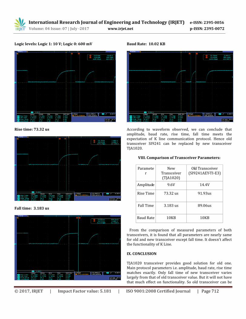
Rise time: 73.32 us
Fall time: 3.183 us
Baud Rate: 10.02 KB
According to waveform observed, we can conclude that amplitude, baud rate, rise time, fall time meets the expectation of K line communication protocol. Hence old transceiver SI9241 can be replaced by new transceiver TJA1020.
VIII. Comparison of Transceiver Parameters:
Parameter
New Transceiver (TJA1020)
Old Transceiver (SI9241AEY-TI-E3)
Amplitude 9.6V 14.4V
Rise Time 73.32 us 91.93us
Fall Time 3.183 us 89.06us
Baud Rate 10KB 10KB
From the comparison of measured parameters of both transceivers, it is found that all parameters are nearly same for old and new transceiver except fall time. It doesn't affect the functionality of K Line. IX. CONCLUSION TJA1020 transceiver provides good solution for old one. Main protocol parameters i.e. amplitude, baud rate, rise time matches exactly. Only fall time of new transceiver varies largely from that of old transceiver value. But it will not have that much effect on functionality. So old transceiver can be

International Research Journal of Engineering and Technology (IRJET) e-ISSN: 2395-0056
Volume: 04 Issue: 07 | July -2017 www.irjet.net p-ISSN: 2395-0072
© 2017, IRJET | Impact Factor value: 5.181 | ISO 9001:2008 Certified Journal | Page 713
replaced with new one and can be used for communication between vehicle ECU and ODB tester for diagnostic purpose. X. REFERENCES
[1] IS0 9141-2(First edition) “Road vehicles - Diagnostic systems -Part 2: CARB requirements for interchange of digital information.” [2] ISO 9141-3(First edition) “Road vehicles — Diagnostic systems —Part 3: Verification of the communication between vehicle and OBD II scan tool” [3] IS0 9141 (First edition) “Road vehicles - Diagnostic systems - Requirements for interchange of digital information.”