Embed Size (px)
Citation preview

Image Rectifier
Rectifying images for use as layers in MIKE Zero
User Guide
MIKE 2017

2

PLEASE NOTE
COPYRIGHT This document refers to proprietary computer software which is pro-tected by copyright. All rights are reserved. Copying or other repro-duction of this manual or the related programs is prohibited without prior written consent of DHI. For details please refer to your 'DHI Software Licence Agreement'.
LIMITED LIABILITY The liability of DHI is limited as specified in Section III of your 'DHI Software Licence Agreement':
'IN NO EVENT SHALL DHI OR ITS REPRESENTATIVES (AGENTS AND SUPPLIERS) BE LIABLE FOR ANY DAMAGES WHATSOEVER INCLUDING, WITHOUT LIMITATION, SPECIAL, INDIRECT, INCIDENTAL OR CONSEQUENTIAL DAMAGES OR DAMAGES FOR LOSS OF BUSINESS PROFITS OR SAVINGS, BUSINESS INTERRUPTION, LOSS OF BUSINESS INFORMA-TION OR OTHER PECUNIARY LOSS ARISING OUT OF THE USE OF OR THE INABILITY TO USE THIS DHI SOFTWARE PRODUCT, EVEN IF DHI HAS BEEN ADVISED OF THE POSSI-BILITY OF SUCH DAMAGES. THIS LIMITATION SHALL APPLY TO CLAIMS OF PERSONAL INJURY TO THE EXTENT PERMIT-TED BY LAW. SOME COUNTRIES OR STATES DO NOT ALLOW THE EXCLUSION OR LIMITATION OF LIABILITY FOR CONSE-QUENTIAL, SPECIAL, INDIRECT, INCIDENTAL DAMAGES AND, ACCORDINGLY, SOME PORTIONS OF THESE LIMITATIONS MAY NOT APPLY TO YOU. BY YOUR OPENING OF THIS SEALED PACKAGE OR INSTALLING OR USING THE SOFT-WARE, YOU HAVE ACCEPTED THAT THE ABOVE LIMITATIONS OR THE MAXIMUM LEGALLY APPLICABLE SUBSET OF THESE LIMITATIONS APPLY TO YOUR PURCHASE OF THIS SOFT-WARE.'
3

4 MIKE Zero - © DHI

1 Image Rectifier Editor . . . . . . . . . . . . . . . . . . . . . . . . . . . . . . . . 71.1 Introduction . . . . . . . . . . . . . . . . . . . . . . . . . . . . . . . . . . . . 71.2 How to start . . . . . . . . . . . . . . . . . . . . . . . . . . . . . . . . . . . . 81.3 Target Area . . . . . . . . . . . . . . . . . . . . . . . . . . . . . . . . . . . . 81.4 Source and Target Views . . . . . . . . . . . . . . . . . . . . . . . . . . . . 9
1.4.1 Source View . . . . . . . . . . . . . . . . . . . . . . . . . . . . . . 91.4.2 Target View . . . . . . . . . . . . . . . . . . . . . . . . . . . . . . . 10
1.5 Toolbar Functions . . . . . . . . . . . . . . . . . . . . . . . . . . . . . . . . 121.6 Target Point . . . . . . . . . . . . . . . . . . . . . . . . . . . . . . . . . . . 131.7 Example . . . . . . . . . . . . . . . . . . . . . . . . . . . . . . . . . . . . . 13
1.7.1 Input image . . . . . . . . . . . . . . . . . . . . . . . . . . . . . . . 141.7.2 Reference points . . . . . . . . . . . . . . . . . . . . . . . . . . . . 141.7.3 Target area . . . . . . . . . . . . . . . . . . . . . . . . . . . . . . . 151.7.4 Rectify image step-by-step . . . . . . . . . . . . . . . . . . . . . . . 151.7.5 Background image in Bathymetry Editor . . . . . . . . . . . . . . . . 17
Index . . . . . . . . . . . . . . . . . . . . . . . . . . . . . . . . . . . . . . . . . . . . . 19
5

6 MIKE Zero - © DHI

Introduction
1 Image Rectifier Editor
1.1 Introduction
The Image rectifier aka 'ImRec.Exe' is an editor that can be used to rectify raster images.
For those who are unfamiliar with rectification a short introduction to rectifica-tion is given here. Rectification is the process of transforming the data from one grid system to another grid system using an nth order polynomial. Since the pixels of the new grid may not align with the pixels of the original grid, the pixels must be resampled. Resampling is the process of extrapolating data values for the pixels on the new grid from the values of the source pixels. In other words the Image Rectifier can bend and twist a scanned image of a seamap, or anything else, so that it aligns with a coordinate system of a spe-cific map projection.
The rectification process is necessary because an image intended as back-ground in a GIS application not always is aligned with the underlying coordi-nate system. The image can be of a different map projection or simply be distorted by a scanning process.
Figure 1.1 Demo map
The Image Rectifier will use a non rectified image as input and will output a rectified image and a world coordinate file that indirectly assigns coordinates to the image data of the output image. Doing this is referred to as Georefer-encing, which refers to the process of assigning map coordinates to image data. The image data may already be projected onto the desired plane but not yet referenced to the proper coordinate system. Rectification, by defini-
7
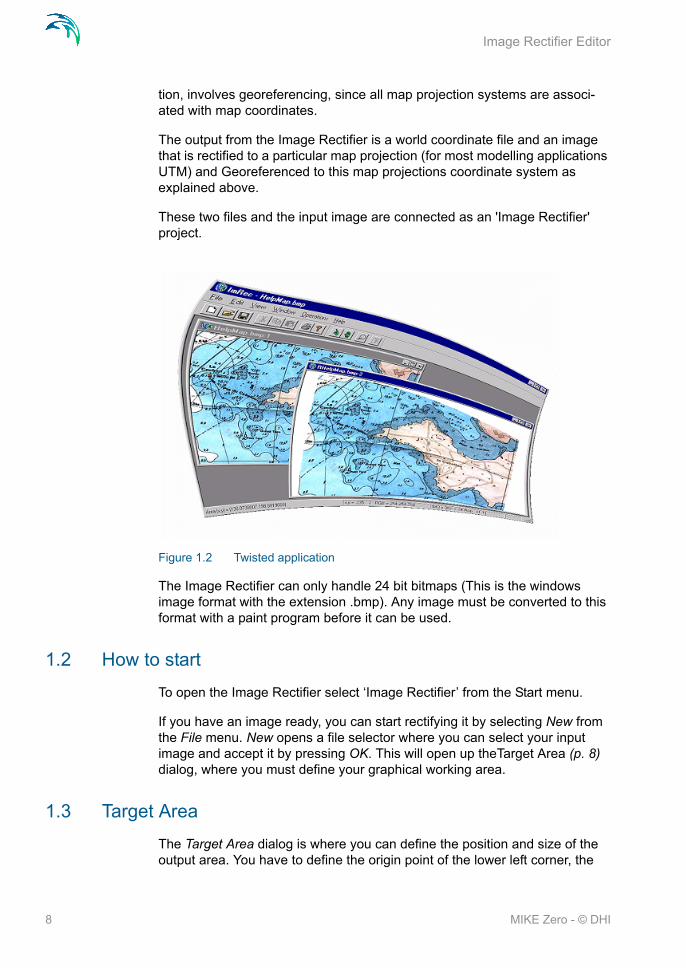
Image Rectifier Editor
tion, involves georeferencing, since all map projection systems are associ-ated with map coordinates.
The output from the Image Rectifier is a world coordinate file and an image that is rectified to a particular map projection (for most modelling applications UTM) and Georeferenced to this map projections coordinate system as explained above.
These two files and the input image are connected as an 'Image Rectifier' project.
Figure 1.2 Twisted application
The Image Rectifier can only handle 24 bit bitmaps (This is the windows image format with the extension .bmp). Any image must be converted to this format with a paint program before it can be used.
1.2 How to start
To open the Image Rectifier select ‘Image Rectifier’ from the Start menu.
If you have an image ready, you can start rectifying it by selecting New from the File menu. New opens a file selector where you can select your input image and accept it by pressing OK. This will open up theTarget Area (p. 8) dialog, where you must define your graphical working area.
1.3 Target Area
The Target Area dialog is where you can define the position and size of the output area. You have to define the origin point of the lower left corner, the
8 MIKE Zero - © DHI

Source and Target Views
width and the height of the output area where the output image will be mapped to.
Figure 1.3 Target Area Settings
Press OK after you have defined these values. These values can be found by analysing the input image. Find a number of key-points that you know or can calculate the output coordinates of to get an idea of the extents of the output area. It is recommended to make the output area a little larger than needed. When you have accepted your values the Source View (p. 9) will appear and you can now use the Toolbar Functions (p. 12).
1.4 Source and Target Views
1.4.1 Source View
The source view is a window that initially shows the input image. This window is used to view the image and place Ground Controls Points (GPCs) at cer-tain user specified positions.
9

Image Rectifier Editor
Figure 1.4 Image Rectifier windows
You can place these points by clicking the Add New GCP Toolbar Functions (p. 12) button which will make the Specify Target Point (p. 13) dialog popup. GCPs are shown in red in the target view, they can be added, deleted and moved via theToolbar Functions (p. 12).
1.4.2 Target View
When all the GCPs have been defined you can rectify the image via the Operations menu. you rectify the image by using a 1st., 2nd. or 3rd. polyno-mia. To make a 1st. order rectification at least 3 GPCs must be defined, to make a 2nd. order rectification at least 6 GPCs must be defined and a 3rd. order rectification needs at least 11 GPCs.
10 MIKE Zero - © DHI

Source and Target Views
Figure 1.5 Operations menu
If you have defined enough GPCs you can select the appropriate Rectifica-tion item in the menu. A progress bar will show the progress of the rectifica-tion and disappear when the rectification is done. To view the output image, select the Target View in the View menu. This will open the target view, which is a window that contains the output image. The target position of the GPCs can be deleted and moved in this view via theToolbar Functions (p. 12).
Figure 1.6 Resulting map
11

Image Rectifier Editor
Notice the 'R' in front of the 'HelpMap.bmp' in the title caption of the Target View. If a project is called 'HelpMap' then the input image will be called 'HelpMap.bmp', the output image will be called 'RHelpMap.bmp' and the world coordinate file will be called 'RHelpMap.bmpw'. If you move the cursor around in the views you can se information about the pixel where the cursor is at in the status bar.
Figure 1.7 Status bar
If the cursor is over a pixel in the focused Target View, the coordinates after the Area (x,y) label is the output area coordinates of that pixel. The informa-tion in the first box is the pixel position and color of the pixel under the cursor in the focused view. The last box contains information on Zoming and image in the focused view.
1.5 Toolbar Functions
The toolbar contains four buttons:
Figure 1.8 The toolbar
1. The Normal Mode button sets the editor in normal mode where you can pick out single GCPs and delete them if that is wanted. To delete you mark one of the GCPs; press delete on the keyboard or choose delete from the edit menu.
2. The Move Mode button sets the editor in a mode where GCPs can be moved by placing the cursor over a GCP and holding the left mouse but-ton down while moving the mouse. When you release the button, the GCP will be placed at the position where the cursor is when the release happens.
3. The Zoom mode button set the editor in a mode where you can zoom in either the input (Source View (p. 9)) or output image (Target View (p. 10)). Left clicking will zoom in and right clicking will zoom out.
12 MIKE Zero - © DHI
Target Point
4. The Add GCP button sets the editor in a mode where you can add GCPs. You add GCPs by pointing at a location in the input image (Source View (p. 9)) and left clicking the mouse. This will make the Spec-ify Target Point (p. 13) dialog popup. This button will not be enabled when the Target View (p. 10) is focused.
1.6 Target Point
To define a Ground Control Point (GPC), you click the Add New GCP Toolbar Functions (p. 12) button when the Source View (p. 9) is focused. Then you click on a position you know the location of in the Source View (p. 9) and the Specify Target Point dialog appears. For maximum accuracy it advised to zoom in to pixel resolution.
Figure 1.9 Definition of target point
Type in the X and the Y and click OK when you are satisfied with the values. Easting and Northing is used here because modelling applications use the UTM system. If you type a value that is outside the extents of the Target View (p. 10) you will be asked to correct the values so that they are valid. If the GPC is accepted, it will be displayed as a red square in the Source View (p. 9) and an Orange square in the Target View (p. 10). The points are num-bered with a label in both views to enable you to see which points are related.
1.7 Example
The following example will show how to rectify an image and use the rectified image in the MIKE Zero bathymetry editor. This example will also show the use at the Southern Hemisphere, with co-ordinates transferred from standard UTM co-ordinates to signed co-ordinates.
Note: Transferring co-ordinates from standard UTM (southern hemisphere) to signed co-ordinates to be used in MIKE Zero, is obtained by subtracting 10.000.000 from the original Northing co-ordinate.
13
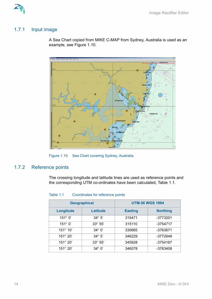
Image Rectifier Editor
1.7.1 Input image
A Sea Chart copied from MIKE C-MAP from Sydney, Australia is used as an example, see Figure 1.10.
Figure 1.10 Sea Chart covering Sydney, Australia.
1.7.2 Reference points
The crossing longitude and latitude lines are used as reference points and the corresponding UTM co-ordinates have been calculated, Table 1.1.
Table 1.1 Coordinates for reference points
Geographical UTM-56 WGS 1984
Longitude Latitude Easting Northing
151 0’ 34 5’ 315471 -3773201
151 0’ 33 55’ 315110 -3754717
151 10’ 34 0’ 330685 -3763671
151 20’ 34 5’ 346229 -3772649
151 20’ 33 55’ 345928 -3754167
151 20’ 34 0’ 346078 -3763408
14 MIKE Zero - © DHI

Example
1.7.3 Target area
To insure that all reference points will fall within the target area the co-ordi-nates and dimension given in Table 1.2 has been selected in order to describe the Sea Chart..
1.7.4 Rectify image step-by-step
Start the Image Rectifier program and load the image Sydney.BMP (24-bit colour) and specify these values as the target area as shown in Figure 1.11.
Figure 1.11 Specify the target area.
Next specify the control points from Table 1.1 as indicated on Figure 1.12.
Table 1.2 Origo and dimention of target area
Origo Easting 315000
Northing -3775000
Dimension Length 32000
Height 21000
15

Image Rectifier Editor
Figure 1.12 Map with control point at crossing lines.
After rectifying the picture the output would look like Figure 1.13.
Figure 1.13 Rectified Map in UTM-56 co-ordinates.
16 MIKE Zero - © DHI
Example
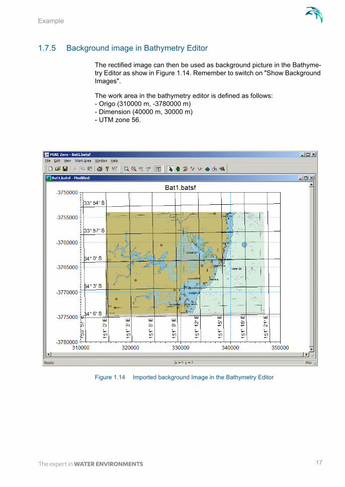
1.7.5 Background image in Bathymetry Editor
The rectified image can then be used as background picture in the Bathyme-try Editor as show in Figure 1.14. Remember to switch on "Show Background Images".
The work area in the bathymetry editor is defined as follows: - Origo (310000 m, -3780000 m)- Dimension (40000 m, 30000 m)- UTM zone 56.
Figure 1.14 Imported background Image in the Bathymetry Editor
17

Image Rectifier Editor
18 MIKE Zero - © DHI

INDEX
19

Index
GGIS application . . . . . . . . . . . . . . 7Ground Control Point . . . . . . . . . . 13Ground Controls Points . . . . . . . . . . 9
MMove Mode . . . . . . . . . . . . . . . 12
NNormal Mode . . . . . . . . . . . . . . 12
OOpen Image Rectifier . . . . . . . . . . . 8
Rrectifification . . . . . . . . . . . . . . 10Resampling . . . . . . . . . . . . . . . . 7
SSouthern Hemisphere . . . . . . . . . 13
TTarget Area . . . . . . . . . . . . . . . . 8Target View . . . . . . . . . . . . . . . 12
ZZoom mode . . . . . . . . . . . . . . . 12
20 MIKE Zero - © DHI