Embed Size (px)
Citation preview

CLASSIC ® 300G
OPERATOR’S MANUAL
For Machines with Code Numbers 10659,10912,11135
IM659-BDecember, 2004
Safety Depends on YouLincoln arc welding equipmentis designed and built with safetyin mind. However, your overallsafety can be increased byproper instal lat ion ... andthoughtful operation on yourpart. DO NOT INSTALL,OPERATE OR REPAIR THISEQUIPMENT WITHOUTREADING THIS MANUAL ANDTHE SAFETY PRECAUTIONSCONTAINED THROUGHOUT.And, most importantly, thinkbefore you act and be careful.
R
• Sales and Service through Subsidiaries and Distributors Worldwide •
Cleveland, Ohio 44117-1199 U.S.A. TEL: 216.481.8100 FAX: 216.486.1751 WEB SITE: www.lincolnelectric.com
• World's Leader in Welding and Cutting Products •
Copyright © 2004 Lincoln Global Inc.
NRTL/C
This manual covers equipment which is no longer in production by The Lincoln Electric Co. Speci�cations and availability of optional features may have changed.

FOR ENGINEpowered equipment.
1.a. Turn the engine off before troubleshooting and maintenancework unless the maintenance work requires it to be running.
____________________________________________________1.b. Operate engines in open, well-ventilated
areas or vent the engine exhaust fumes outdoors.
____________________________________________________1.c. Do not add the fuel near an open flame
welding arc or when the engine is running.Stop the engine and allow it to cool beforerefueling to prevent spilled fuel from vaporiz-ing on contact with hot engine parts andigniting. Do not spill fuel when filling tank. Iffuel is spilled, wipe it up and do not startengine until fumes have been eliminated.
____________________________________________________1.d. Keep all equipment safety guards, covers and devices in
position and in good repair.Keep hands, hair, clothing andtools away from V-belts, gears, fans and all other movingparts when starting, operating or repairing equipment.
____________________________________________________
1.e. In some cases it may be necessary to remove safetyguards to perform required maintenance. Removeguards only when necessary and replace them when themaintenance requiring their removal is complete.Always use the greatest care when working near movingparts.
___________________________________________________1.f. Do not put your hands near the engine fan.
Do not attempt to override the governor oridler by pushing on the throttle control rodswhile the engine is running.
___________________________________________________1.g. To prevent accidentally starting gasoline engines while
turning the engine or welding generator during maintenancework, disconnect the spark plug wires, distributor cap ormagneto wire as appropriate.
iSAFETYi
ARC WELDING CAN BE HAZARDOUS. PROTECT YOURSELF AND OTHERS FROM POSSIBLE SERIOUS INJURY OR DEATH.KEEP CHILDREN AWAY. PACEMAKER WEARERS SHOULD CONSULT WITH THEIR DOCTOR BEFORE OPERATING.
Read and understand the following safety highlights. For additional safety information, it is strongly recommended that youpurchase a copy of “Safety in Welding & Cutting - ANSI Standard Z49.1” from the American Welding Society, P.O. Box351040, Miami, Florida 33135 or CSA Standard W117.2-1974. A Free copy of “Arc Welding Safety” booklet E205 is availablefrom the Lincoln Electric Company, 22801 St. Clair Avenue, Cleveland, Ohio 44117-1199.
BE SURE THAT ALL INSTALLATION, OPERATION, MAINTENANCE AND REPAIR PROCEDURES AREPERFORMED ONLY BY QUALIFIED INDIVIDUALS.
WARNING
Mar ‘95
ELECTRIC AND MAGNETIC FIELDSmay be dangerous
2.a. Electric current flowing through any conductor causes localized Electric and Magnetic Fields (EMF). Welding current creates EMF fields around welding cables and welding machines
2.b. EMF fields may interfere with some pacemakers, andwelders having a pacemaker should consult their physicianbefore welding.
2.c. Exposure to EMF fields in welding may have other healtheffects which are now not known.
2.d. All welders should use the following procedures in order tominimize exposure to EMF fields from the welding circuit:
2.d.1. Route the electrode and work cables together - Securethem with tape when possible.
2.d.2. Never coil the electrode lead around your body.
2.d.3. Do not place your body between the electrode andwork cables. If the electrode cable is on your right side, the work cable should also be on your right side.
2.d.4. Connect the work cable to the workpiece as close aspossible to the area being welded.
2.d.5. Do not work next to welding power source.
1.h. To avoid scalding, do not remove theradiator pressure cap when the engine ishot.
CALIFORNIA PROPOSITION 65 WARNINGS
Diesel engine exhaust and some of its constituentsare known to the State of California to cause can-cer, birth defects, and other reproductive harm.
The engine exhaust from this product containschemicals known to the State of California to causecancer, birth defects, or other reproductive harm.
The Above For Diesel Engines The Above For Gasoline Engines
iiSAFETYii
ARC RAYS can burn.4.a. Use a shield with the proper filter and cover
plates to protect your eyes from sparks andthe rays of the arc when welding or observingopen arc welding. Headshield and filter lensshould conform to ANSI Z87. I standards.
4.b. Use suitable clothing made from durable flame-resistantmaterial to protect your skin and that of your helpers fromthe arc rays.
4.c. Protect other nearby personnel with suitable, non-flammablescreening and/or warn them not to watch the arc nor exposethemselves to the arc rays or to hot spatter or metal.
ELECTRIC SHOCK cankill.3.a. The electrode and work (or ground) circuits
are electrically “hot” when the welder is on.Do not touch these “hot” parts with your bareskin or wet clothing. Wear dry, hole-free
gloves to insulate hands.
3.b. Insulate yourself from work and ground using dry insulation.Make certain the insulation is large enough to cover your fullarea of physical contact with work and ground.
In addition to the normal safety precautions, if weldingmust be performed under electrically hazardousconditions (in damp locations or while wearing wetclothing; on metal structures such as floors, gratings orscaffolds; when in cramped positions such as sitting,kneeling or lying, if there is a high risk of unavoidable oraccidental contact with the workpiece or ground) usethe following equipment:
• Semiautomatic DC Constant Voltage (Wire) Welder.• DC Manual (Stick) Welder.• AC Welder with Reduced Voltage Control.
3.c. In semiautomatic or automatic wire welding, the electrode,electrode reel, welding head, nozzle or semiautomaticwelding gun are also electrically “hot”.
3.d. Always be sure the work cable makes a good electricalconnection with the metal being welded. The connectionshould be as close as possible to the area being welded.
3.e. Ground the work or metal to be welded to a good electrical(earth) ground.
3.f. Maintain the electrode holder, work clamp, welding cable andwelding machine in good, safe operating condition. Replacedamaged insulation.
3.g. Never dip the electrode in water for cooling.
3.h. Never simultaneously touch electrically “hot” parts ofelectrode holders connected to two welders because voltagebetween the two can be the total of the open circuit voltageof both welders.
3.i. When working above floor level, use a safety belt to protectyourself from a fall should you get a shock.
3.j. Also see Items 6.c. and 8.
FUMES AND GASEScan be dangerous.5.a. Welding may produce fumes and gases
hazardous to health. Avoid breathing thesefumes and gases.When welding, keepyour head out of the fume. Use enoughventilation and/or exhaust at the arc to keep
fumes and gases away from the breathing zone. Whenwelding with electrodes which require specialventilation such as stainless or hard facing (seeinstructions on container or MSDS) or on lead orcadmium plated steel and other metals or coatingswhich produce highly toxic fumes, keep exposure aslow as possible and below Threshold Limit Values (TLV)using local exhaust or mechanical ventilation. Inconfined spaces or in some circumstances, outdoors, arespirator may be required. Additional precautions arealso required when welding on galvanized steel.
5.b. Do not weld in locations near chlorinated hydrocarbon vaporscoming from degreasing, cleaning or spraying operations.The heat and rays of the arc can react with solvent vapors toform phosgene, a highly toxic gas, and other irritating prod-ucts.
5.c. Shielding gases used for arc welding can displace air andcause injury or death. Always use enough ventilation,especially in confined areas, to insure breathing air is safe.
5.d. Read and understand the manufacturer’s instructions for thisequipment and the consumables to be used, including thematerial safety data sheet (MSDS) and follow youremployer’s safety practices. MSDS forms are available fromyour welding distributor or from the manufacturer.
5.e. Also see item 1.b.
Mar ‘95
FOR ELECTRICALLYpowered equipment.
8.a. Turn off input power using the disconnectswitch at the fuse box before working onthe equipment.
8.b. Install equipment in accordance with the U.S. NationalElectrical Code, all local codes and the manufacturer’srecommendations.
8.c. Ground the equipment in accordance with the U.S. NationalElectrical Code and the manufacturer’s recommendations.
CYLINDER may explodeif damaged.7.a. Use only compressed gas cylinders
containing the correct shielding gas for theprocess used and properly operatingregulators designed for the gas and
pressure used. All hoses, fittings, etc. should be suitable forthe application and maintained in good condition.
7.b. Always keep cylinders in an upright position securelychained to an undercarriage or fixed support.
7.c. Cylinders should be located:• Away from areas where they may be struck or subjected tophysical damage.
• A safe distance from arc welding or cutting operations andany other source of heat, sparks, or flame.
7.d. Never allow the electrode, electrode holder or any otherelectrically “hot” parts to touch a cylinder.
7.e. Keep your head and face away from the cylinder valve outletwhen opening the cylinder valve.
7.f. Valve protection caps should always be in place and handtight except when the cylinder is in use or connected foruse.
7.g. Read and follow the instructions on compressed gascylinders, associated equipment, and CGA publication P-l,“Precautions for Safe Handling of Compressed Gases inCylinders,” available from the Compressed Gas Association1235 Jefferson Davis Highway, Arlington, VA 22202.
iiiSAFETYiii
Mar ‘95
WELDING SPARKS cancause fire or explosion.6.a. Remove fire hazards from the welding area.
If this is not possible, cover them to preventthe welding sparks from starting a fire.Remember that welding sparks and hot
materials from welding can easily go through small cracksand openings to adjacent areas. Avoid welding nearhydraulic lines. Have a fire extinguisher readily available.
6.b. Where compressed gases are to be used at the job site,special precautions should be used to prevent hazardoussituations. Refer to “Safety in Welding and Cutting” (ANSIStandard Z49.1) and the operating information for theequipment being used.
6.c. When not welding, make certain no part of the electrodecircuit is touching the work or ground. Accidental contactcan cause overheating and create a fire hazard.
6.d. Do not heat, cut or weld tanks, drums or containers until theproper steps have been taken to insure that such procedureswill not cause flammable or toxic vapors from substancesinside. They can cause an explosion even though they havebeen “cleaned”. For information, purchase “RecommendedSafe Practices for the Preparation for Welding and Cutting ofContainers and Piping That Have Held HazardousSubstances”, AWS F4.1 from the American Welding Society(see address above).
6.e. Vent hollow castings or containers before heating, cutting orwelding. They may explode.
6.f. Sparks and spatter are thrown from the welding arc. Wear oilfree protective garments such as leather gloves, heavy shirt,cuffless trousers, high shoes and a cap over your hair. Wearear plugs when welding out of position or in confined places.Always wear safety glasses with side shields when in awelding area.
6.g. Connect the work cable to the work as close to the weldingarea as practical. Work cables connected to the buildingframework or other locations away from the welding areaincrease the possibility of the welding current passingthrough lifting chains, crane cables or other alternate cir-cuits. This can create fire hazards or overheat lifting chainsor cables until they fail.
6.h. Also see item 1.c.

ivSAFETYiv
Mar. ‘93
PRÉCAUTIONS DE SÛRETÉPour votre propre protection lire et observer toutes les instructionset les précautions de sûreté specifiques qui parraissent dans cemanuel aussi bien que les précautions de sûreté générales suiv-antes:
Sûreté Pour Soudage A L’Arc1. Protegez-vous contre la secousse électrique:
a. Les circuits à l’électrode et à la piéce sont sous tensionquand la machine à souder est en marche. Eviter toujourstout contact entre les parties sous tension et la peau nueou les vétements mouillés. Porter des gants secs et sanstrous pour isoler les mains.
b. Faire trés attention de bien s’isoler de la masse quand onsoude dans des endroits humides, ou sur un planchermetallique ou des grilles metalliques, principalement dans les positions assis ou couché pour lesquelles une grandepartie du corps peut être en contact avec la masse.
c. Maintenir le porte-électrode, la pince de masse, le câblede soudage et la machine à souder en bon et sûr étatdefonctionnement.
d.Ne jamais plonger le porte-électrode dans l’eau pour lerefroidir.
e. Ne jamais toucher simultanément les parties sous tensiondes porte-électrodes connectés à deux machines à souderparce que la tension entre les deux pinces peut être letotal de la tension à vide des deux machines.
f. Si on utilise la machine à souder comme une source decourant pour soudage semi-automatique, ces precautionspour le porte-électrode s’applicuent aussi au pistolet desoudage.
2. Dans le cas de travail au dessus du niveau du sol, se protégercontre les chutes dans le cas ou on recoit un choc. Ne jamaisenrouler le câble-électrode autour de n’importe quelle partiedu corps.
3. Un coup d’arc peut être plus sévère qu’un coup de soliel,donc:
a. Utiliser un bon masque avec un verre filtrant appropriéainsi qu’un verre blanc afin de se protéger les yeux du ray-onnement de l’arc et des projections quand on soude ouquand on regarde l’arc.
b. Porter des vêtements convenables afin de protéger lapeau de soudeur et des aides contre le rayonnement del‘arc.
c. Protéger l’autre personnel travaillant à proximité ausoudage à l’aide d’écrans appropriés et non-inflammables.
4. Des gouttes de laitier en fusion sont émises de l’arc desoudage. Se protéger avec des vêtements de protection libresde l’huile, tels que les gants en cuir, chemise épaisse, pan-talons sans revers, et chaussures montantes.
5. Toujours porter des lunettes de sécurité dans la zone desoudage. Utiliser des lunettes avec écrans lateraux dans leszones où l’on pique le laitier.
6. Eloigner les matériaux inflammables ou les recouvrir afin deprévenir tout risque d’incendie dû aux étincelles.
7. Quand on ne soude pas, poser la pince à une endroit isolé dela masse. Un court-circuit accidental peut provoquer unéchauffement et un risque d’incendie.
8. S’assurer que la masse est connectée le plus prés possiblede la zone de travail qu’il est pratique de le faire. Si on placela masse sur la charpente de la construction ou d’autresendroits éloignés de la zone de travail, on augmente le risquede voir passer le courant de soudage par les chaines de lev-age, câbles de grue, ou autres circuits. Cela peut provoquerdes risques d’incendie ou d’echauffement des chaines et descâbles jusqu’à ce qu’ils se rompent.
9. Assurer une ventilation suffisante dans la zone de soudage.Ceci est particuliérement important pour le soudage de tôlesgalvanisées plombées, ou cadmiées ou tout autre métal quiproduit des fumeés toxiques.
10. Ne pas souder en présence de vapeurs de chlore provenantd’opérations de dégraissage, nettoyage ou pistolage. Lachaleur ou les rayons de l’arc peuvent réagir avec les vapeursdu solvant pour produire du phosgéne (gas fortement toxique)ou autres produits irritants.
11. Pour obtenir de plus amples renseignements sur la sûreté,voir le code “Code for safety in welding and cutting” CSAStandard W 117.2-1974.
PRÉCAUTIONS DE SÛRETÉ POURLES MACHINES À SOUDER ÀTRANSFORMATEUR ET ÀREDRESSEUR
1. Relier à la terre le chassis du poste conformement au code del’électricité et aux recommendations du fabricant. Le dispositifde montage ou la piece à souder doit être branché à unebonne mise à la terre.
2. Autant que possible, I’installation et l’entretien du poste seronteffectués par un électricien qualifié.
3. Avant de faires des travaux à l’interieur de poste, la debranch-er à l’interrupteur à la boite de fusibles.
4. Garder tous les couvercles et dispositifs de sûreté à leurplace.

vv
Thank You for selecting a QUALITY product by Lincoln Electric. We want youto take pride in operating this Lincoln Electric Company product••• as much pride as we have in bringing this product to you!
Read this Operators Manual completely before attempting to use this equipment. Save this manual and keep ithandy for quick reference. Pay particular attention to the safety instructions we have provided for your protection.The level of seriousness to be applied to each is explained below:
WARNINGThis statement appears where the information must be followed exactly to avoid serious personal injury orloss of life.
This statement appears where the information must be followed to avoid minor personal injury or damage tothis equipment.
CAUTION
Please Examine Carton and Equipment For Damage ImmediatelyWhen this equipment is shipped, title passes to the purchaser upon receipt by the carrier. Consequently, Claimsfor material damaged in shipment must be made by the purchaser against the transportation company at thetime the shipment is received.
Please record your equipment identification information below for future reference. This information can befound on your machine nameplate.
Product _________________________________________________________________________________
Model Number ___________________________________________________________________________
Code Number or Date Code_________________________________________________________________
Serial Number____________________________________________________________________________
Date Purchased___________________________________________________________________________
Where Purchased_________________________________________________________________________
Whenever you request replacement parts or information on this equipment, always supply the information youhave recorded above. The code number is especially important when identifying the correct replacement parts.
On-Line Product Registration
- Register your machine with Lincoln Electric either via fax or over the Internet.
• For faxing: Complete the form on the back of the warranty statement included in the literature packetaccompanying this machine and fax the form per the instructions printed on it.
• For On-Line Registration: Go to our WEB SITE at www.lincolnelectric.com. Choose “Quick Links” and then“Product Registration”. Please complete the form and submit your registration.

vivi TABLE OF CONTENTS
Page
Installation .......................................................................................................Section ATechnical Specifications ........................................................................................A-1Safety Precautions.................................................................................................A-2Pre-Operation Installation ......................................................................................A-2
Exhaust Spark Arrester ...................................................................................A-2Location/Ventilation.........................................................................................A-2Machine Grounding.........................................................................................A-2Lift Bail ............................................................................................................A-2Trailers ............................................................................................................A-2Polarity Control and Cable Sizes ....................................................................A-3
Pre-Operation Service ...........................................................................................A-3Oil ....................................................................................................................A-3Fuel .................................................................................................................A-3Cooling System ...............................................................................................A-3Battery Charging .............................................................................................A-4
Operation .........................................................................................................Section BGeneral Description ...............................................................................................B-1Design Features ....................................................................................................B-1
Starting The GM 3.0L Engine..........................................................................B-2Stopping the engine ........................................................................................B-2
Welder Operation...................................................................................................B-2Duty Cycle.......................................................................................................B-2Control of Welding Current..............................................................................B-3Idler Operation ................................................................................................B-3Auxiliary Power ...............................................................................................B-3Throttle Body Deicing......................................................................................B-3
Accessories .....................................................................................................Section COptional Equipment (Field Installed) .....................................................................C-1
Maintenance ....................................................................................................Section DSafety Precautions ................................................................................................D-1General Instructions ..............................................................................................D-1Cooling System .....................................................................................................D-1Bearings ................................................................................................................D-1Commutator and Brushes .....................................................................................D-1Idler Control Maintenance .....................................................................................D-2Nameplates ...........................................................................................................D-2Purging Air from Fuel System................................................................................D-2Engine Maintenance .............................................................................................D-2Engine Service Chart ............................................................................................D-3
Troubleshooting ..............................................................................................Section ESafety Precautions.................................................................................................E-1Troubleshooting ..............................................................................................E-2,E-3Electronic Idler Troubleshooting Guide...........................................................E-4,E-5Troubleshooting .....................................................................................E-5, E-6,E-7
Diagrams ..........................................................................................................Section FWiring Diagram (Classic 300G) .......................................................................F-1,F-2Dimension Print......................................................................................................F-3
Parts List ......................................................................................................P379 Series

TECHNICAL SPECIFICATIONS – CLASSIC 300G (K1754-1)
CLASSIC 300G
A-1INSTALLATION A-1
DC CURRENT RANGEFine Adjustment in each Range
40-350 Amps
DUTY CYCLE
100%
60%
RATED DC OUTPUT*VOLTS @ RATED AMPS
30V @ 250A
NEMA Rating32V @ 300A
(1) 115V will operate either 60 Hz. or 50/60 Hz. power tools, lights etc.
* Based on a 10 min. period.
Make/Model Description Speed (RPM) Displacement Ignition Capacitiescu. in. (Ltrs.) System
High Idle 1800 Delco Voyager Fuel: 15 gal.4 Cylinder High Energy 57 Ltrs.
GM 4 Cycle
3.0 Liter Water-Cooled Full Load 1800 Distributor Type Oil: 4.5 Qts. Gasoline Engine 4.3 Ltrs.
Classic 300G Cast Iron Cylinder 183.0(3.0) Electronic(K1754-1) Block/Crankcase Low Idle 1360
53.0 HP @1800 RPM
INPUT - GASOLINE ENGINE
RATED OUTPUT - WELDER
HEIGHT WIDTH DEPTH WEIGHT
40.94** in. 24.00 in. 66.91in.1039.9 mm 609.6 mm 1700 mm 1330 lbs. (603kg.)
**Top of enclosure, add 8.0” (203.2mm) for exhaust
OUTPUT - GENERATORAuxiliary Power 1
3000 Watts, 60 Hz. AC (26 Amps @ 115V), (13 Amps @ 230V)
PHYSICAL DIMENSIONS
ENGINE OPERATING LOAD FUEL CONSUMPTION
Cooling 9.9 Qts.9.4 Ltrs.
DESCRIPTION
300 Amp DC Welder
All Copper Windings
Pure DC Power
Generator
Low Idle (1360 RPM)-No Load High Idle (1800 RPM)-No Load AC Auxiliary-115 Volts-26 Amps
50 Amps @ 22 Volts @ 60% Duty Cycle100 Amps @ 24 Volts @ 60 % Duty Cycle150 Amps @ 26 Volts @ 60% Duty Cycle200 Amps @ 28 Volts @ 60 % Duty Cycle250 Amps @ 30 Volts @ 60 % Duty Cycle300 Amps @ 32 Volts @ 60 % Duty Cycle250 Amps @ 30 Volts @ 100 % Duty Cycle
.89 gal/hr (3.37 ltrs/hr)1.32 gal/hr (5.00 ltrs/hr)1.42 gal/hr (5.32 ltrs/hr)1.24 gal/hr (4.70 ltrs/hr)1.27 gal/hr (4.82 ltrs/hr)1.33 gal/hr (5.04 ltrs/hr)1.47 gal/hr (5.57 ltrs/hr)1.66 gal/hr (6.27 ltrs/hr)1.83 gal/hr (6.91 ltrs/hr)2.15 gal/hr (8.12 ltrs/hr)
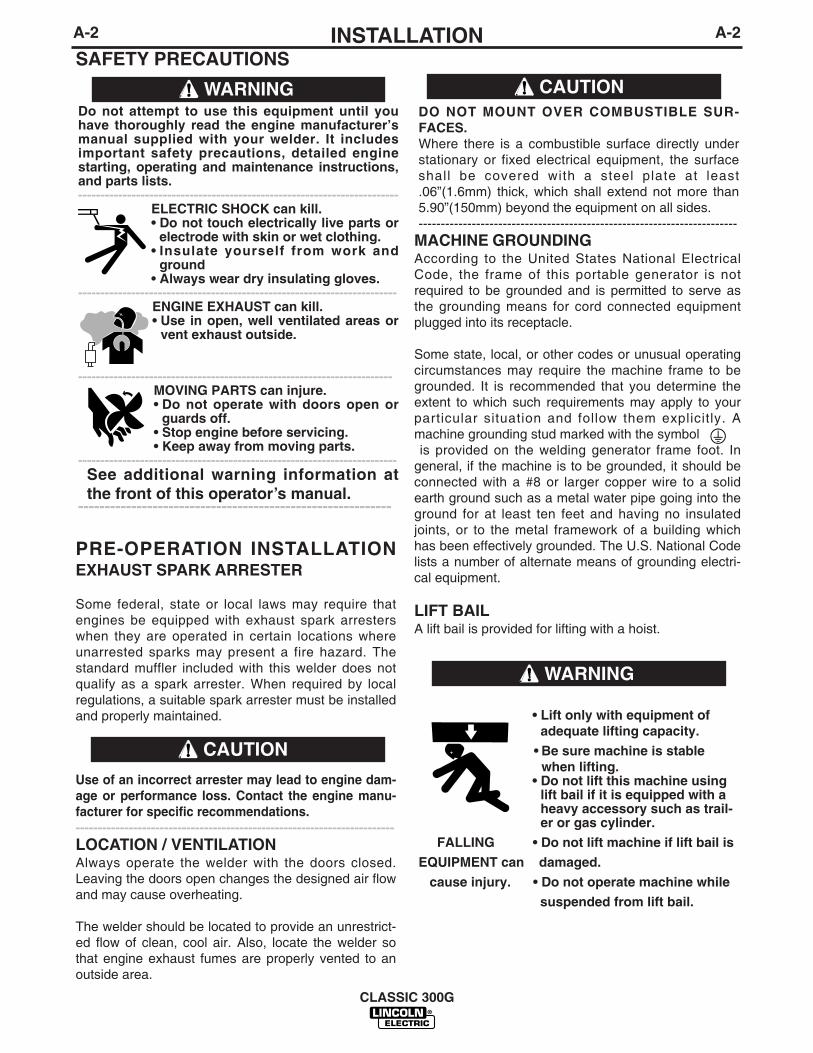
PRE-OPERATION INSTALLATIONEXHAUST SPARK ARRESTER
Some federal, state or local laws may require thatengines be equipped with exhaust spark arresterswhen they are operated in certain locations whereunarrested sparks may present a fire hazard. Thestandard muffler included with this welder does notqualify as a spark arrester. When required by localregulations, a suitable spark arrester must be installedand properly maintained.
Use of an incorrect arrester may lead to engine dam-age or performance loss. Contact the engine manu-facturer for specific recommendations.------------------------------------------------------------------------LOCATION / VENTILATION Always operate the welder with the doors closed.Leaving the doors open changes the designed air flowand may cause overheating.
The welder should be located to provide an unrestrict-ed flow of clean, cool air. Also, locate the welder sothat engine exhaust fumes are properly vented to anoutside area.
MACHINE GROUNDINGAccording to the United States National ElectricalCode, the frame of this portable generator is notrequired to be grounded and is permitted to serve asthe grounding means for cord connected equipmentplugged into its receptacle.
Some state, local, or other codes or unusual operatingcircumstances may require the machine frame to begrounded. It is recommended that you determine theextent to which such requirements may apply to yourparticular situation and follow them explicitly. Amachine grounding stud marked with the symbolis provided on the welding generator frame foot. In
general, if the machine is to be grounded, it should beconnected with a #8 or larger copper wire to a solidearth ground such as a metal water pipe going into theground for at least ten feet and having no insulatedjoints, or to the metal framework of a building whichhas been effectively grounded. The U.S. National Codelists a number of alternate means of grounding electri-cal equipment.
LIFT BAILA lift bail is provided for lifting with a hoist.
Do not attempt to use this equipment until youhave thoroughly read the engine manufacturer’smanual supplied with your welder. It includesimportant safety precautions, detailed enginestarting, operating and maintenance instructions,and parts lists.------------------------------------------------------------------------
ELECTRIC SHOCK can kill.• Do not touch electrically live parts or
electrode with skin or wet clothing.• Insulate yourself from work and
ground• Always wear dry insulating gloves.
------------------------------------------------------------------------ENGINE EXHAUST can kill.• Use in open, well ventilated areas or
vent exhaust outside.
-----------------------------------------------------------------------MOVING PARTS can injure.• Do not operate with doors open or
guards off.• Stop engine before servicing.• Keep away from moving parts.
------------------------------------------------------------------------See additional warning information atthe front of this operator’s manual.
-----------------------------------------------------------
WARNING
CAUTION
A-2INSTALLATION
CLASSIC 300G
A-2
SAFETY PRECAUTIONS
• Lift only with equipment ofadequate lifting capacity.
• Be sure machine is stablewhen lifting.
• Do not lift this machine usinglift bail if it is equipped with aheavy accessory such as trail-er or gas cylinder.
FALLING • Do not lift machine if lift bail is
EQUIPMENT can damaged.
cause injury. • Do not operate machine while
suspended from lift bail.
WARNING
DO NOT MOUNT OVER COMBUSTIBLE SUR-FACES.Where there is a combustible surface directly understationary or fixed electrical equipment, the surfaceshall be covered with a steel plate at least.06”(1.6mm) thick, which shall extend not more than5.90”(150mm) beyond the equipment on all sides.------------------------------------------------------------------------
CAUTION
PRE-OPERATION SERVICE
READ the engine operating and maintenance instruc-tions supplied with this machine.
OILThis unit is supplied from the factory with the enginecrankcase filled with a high quality SAE 10W/30 oil.This oil should be acceptable for most typical ambienttemperatures.Consult the engine operation manual for specificengine manufacturer’s recommendations. Upon receiptof the welder, check the engine dipstick to be sure theoil is at the “full” mark. DO NOT overfill.
FUELFill the fuel tank with the grade of fuel recommended inthe Engine Operator’s manual. Make sure the fuelvalves on the sediment bowl and the water separatorare in the open positions.
COOLING SYSTEMThe radiator has been filled at the factory with a 50-50mixture of ethylene glycol antifreeze and water. Checkthe radiator level and add a 50-50 solution as needed(see engine manual or antifreeze container for alter-nate antifreeze recommendations)
CAUTION
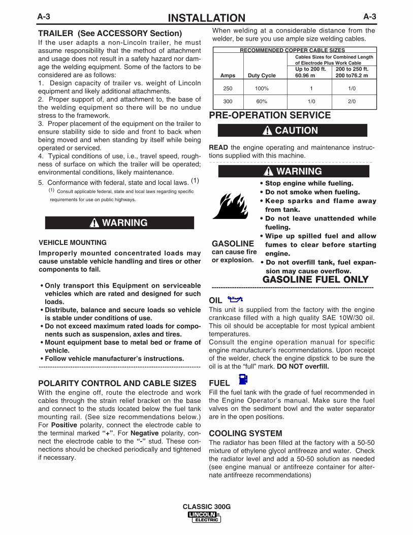
When welding at a considerable distance from thewelder, be sure you use ample size welding cables.
RECOMMENDED COPPER CABLE SIZESCables Sizes for Combined Lengthof Electrode Plus Work CableUp to 200 ft. 200 to 250 ft.
Amps Duty Cycle 60.96 m 200 to76.2 m
250 100% 1 1/0
300 60% 1/0 2/0
A-3INSTALLATION
CLASSIC 300G
A-3
TRAILER (See ACCESSORY Section) If the user adapts a non-Lincoln trailer, he mustassume responsibility that the method of attachmentand usage does not result in a safety hazard nor dam-age the welding equipment. Some of the factors to beconsidered are as follows:1. Design capacity of trailer vs. weight of Lincolnequipment and likely additional attachments.2. Proper support of, and attachment to, the base ofthe welding equipment so there will be no unduestress to the framework.3. Proper placement of the equipment on the trailer toensure stability side to side and front to back whenbeing moved and when standing by itself while beingoperated or serviced.4. Typical conditions of use, i.e., travel speed, rough-ness of surface on which the trailer will be operated;environmental conditions, likely maintenance.
5. Conformance with federal, state and local laws. (1)(1) Consult applicable federal, state and local laws regarding specific
requirements for use on public highways.
POLARITY CONTROL AND CABLE SIZESWith the engine off, route the electrode and workcables through the strain relief bracket on the baseand connect to the studs located below the fuel tankmounting rail. (See size recommendations below.)For Positive polarity, connect the electrode cable tothe terminal marked “+”. For Negative polarity, con-nect the electrode cable to the “-” stud. These con-nections should be checked periodically and tightenedif necessary.
• Stop engine while fueling.• Do not smoke when fueling.• Keep sparks and flame away
from tank.• Do not leave unattended while
fueling.• Wipe up spilled fuel and allow
fumes to clear before startingengine.
• Do not overfill tank, fuel expan-sion may cause overflow.
GASOLINE FUEL ONLY------------------------------------------------------------------------
WARNING
GASOLINEcan cause fireor explosion.
VEHICLE MOUNTING
Improperly mounted concentrated loads maycause unstable vehicle handling and tires or othercomponents to fail.
• Only transport this Equipment on serviceablevehicles which are rated and designed for suchloads.
• Distribute, balance and secure loads so vehicleis stable under conditions of use.
• Do not exceed maximum rated loads for compo-nents such as suspension, axles and tires.
• Mount equipment base to metal bed or frame ofvehicle.
• Follow vehicle manufacturer’s instructions.------------------------------------------------------------------------
WARNING

BATTERY CHARGING
The Classic 300G is equipped with a wet charged bat-tery. The charging current is automatically regulatedwhen the battery is low (after starting the engine) to atrickle current when the battery is fully charged.
When replacing, jumping or otherwise connecting thebattery to the battery cables, the proper polarity mustbe observed. This system is NEGATIVE GROUND.
GASES FROM BATTERY can explode.• Keep sparks, flame and cigarettes
away.
BATTERY ACID can burn eyes andskin.• Wear gloves and eye protection and
be careful when boosting, chargingor working near battery.
To prevent EXPLOSION when:• Installing a new battery - disconnect the nega-
tive cable from the old battery first and connectthe negative cable to the new battery last.
• Connecting a battery charger remove the batteryfrom the welder by disconnecting the negativecable first, then the positive cable and batteryclamp. When reinstalling, connect the negativecable last.
• Using a booster - connect the positive lead tothe battery first, then connect the negative leadto the ground lead on the base.
To prevent ELECTRICAL DAMAGE when:• Installing a new battery.• Using a booster.
Use correct polarity - Negative Ground.
• To prevent BATTERY DISCHARGE, if you havean ignition switch, turn it off when engine is notrunning.
• To prevent BATTERY BUCKLING, tighten nuts onbattery clamp until snug.
------------------------------------------------------------------------
WARNING
A-4INSTALLATION
CLASSIC 300G
A-4

B-1OPERATIONB-1
SAFETY PRECAUTIONS
Operate the welder with the doors closed. Leaving thedoors open changes the designed air flow and can causeoverheating.
GENERAL DESCRIPTION
The Classic® 300G is a heavy duty, engine driven, DCarc welding power source, capable of providing constantcurrent output for stick welding or DC TIG welding. Thiswelder is wound with all copper coils, rated at 300amps/32 Volts, and provides other Classic features suchas improved door latches and stainless hinges. With the
addition of the optional K623-1 Wire Feed Module™ theClassic 300G will provide constant voltage output for run-ning the LN-7, LN-23P, or LN-25 wire feeders. Theoptional K924-4 Remote Control Kit (field installed) pro-vides a switch, or K924-5 Remote Control Kits provide areceptacle and a remote control rheostat for remote finecurrent and open circuit voltage adjustment.
The Classic 300G has an electronic Engine Protectionsystem. In the event of sudden low oil pressure or highcoolant temperature, the engine immediately shuts down.The Classic 300G has a current range of 40-350 DCamps with output ratings as follows:These units are also capable of providing 3 kVA of115/230 volts of 60 cycle AC auxiliary power.
CLASSIC 300G
Do not attempt to use this equipment until youhave thoroughly read the engine manufacturer’smanual supplied with your welder. It includesimportant safety precautions, detailed enginestarting, operating and maintenance instructions,and parts lists.------------------------------------------------------------------------
ELECTRIC SHOCK can kill.• Do not touch electrically live parts or
electrode with skin or wet clothing.• Insulate yourself from work and
ground• Always wear dry insulating gloves.
------------------------------------------------------------------------ENGINE EXHAUST can kill.• Use in open, well ventilated areas or
vent exhaust outside.
----------------------------------------------------
MOVING PARTS can injure.• Do not operate with doors open or
guards off.• Stop engine before servicing.• Keep away from moving parts.
------------------------------------------------------------------------See additional warning information at thefront of this operator’s manual.
WARNING DO NOT MOUNT OVER COMBUSTIBLE SURFACES.Where there is a combustible surface directly understationary or fixed electrical equipment, the surfaceshall be covered with a steel plate at least.06”(1.6mm) thick, which shall extend not more than5.90”(150mm) beyond the equipment on all sides.------------------------------------------------------------------------The Classic 300G uses the GM 3.0L industrial water-cooled gasoline engine.
DESIGN FEATURES
Control Panel
Both the engine and the welder controls are located onone recessed panel at the exciter end of the machine.The welder controls consist of a five step “Current RangeSelector” switch and a “Fine Current Adjustment” rheo-stat. The welder is equipped with a “Start” button, an“Ignition” switch, an “Idler” control switch, and a “GlowPlug” button for easier cold weather starting.
The control panel also contains an engine temperaturegauge, a battery charging ammeter, an oil pressuregauge, two three prong grounding type receptacles andfour circuit breakers for auxiliary power.
All Copper Windings - For long life and dependableoperation.
Engine Idler Control - The Classic 300G is equippedwith an electronic automatic engine idle control. It auto-matically increases and decreases engine speed whenstarting and stopping welding or using auxiliarypower. A built-in time delay permits changing electrodesbefore the engine slows to its low idle speed. The “Idler”control switch on the panel locks the idler in high idleposition when desired.
Auxiliary Power - 3.0 kVA of nominal 115/230V, 60Hz,AC. Output voltage is maintained within ± 10% at allloads up to rated capacity. (See Optional Features forPower Plug Kit.)
Welder Enclosure - The complete welder is rubbermounted on a rugged steel “C” channel base.
The output terminals are placed at the side of themachines so that they are protected by the door. Theoutput terminals are labeled (+) and (-).
Cranking System - A 12 volt electric starter is standard.
250A @ 30V300A @ 32V
100%60%
RATED OUTPUT DUTY CYCLE
CAUTION

• When hauling the welder between job sites, closethe fuel feed valve beneath the fuel tank.
• If the fuel supply is cut off or runs out while the fuelpump is operating, air may be entrapped in the fueldistribution system. If this happens, bleeding of thefuel system may be necessary. Refer to the instruc-tions in the MAINTENANCE section of this manual.
REFER TO THE ENGINE
Operation and maintenance manual for additionalinformation on the engine supplied with this welder.
WELDER OPERATION
DUTY CYCLE
The NEMA output rating of the Classic 300G is 300amperes at 32 arc volts on a 60% duty cycle (consultSpecifications in this manual for alternate ratings).Duty cycle is based on a ten minute period; thus, thewelder can be loaded at rated output for six minutesout of every ten minute period.
B-2OPERATIONB-2
CLASSIC 300G
ELECTRIC SHOCK can kill.• Do not touch electrically live parts or
electrode with skin or wet clothing.• Insulate yourself from work and ground.
FUMES & GASES can be dangerous.• Keep your head out of the fumes.• Use ventilation or exhaust to remove
fumes from breathing zone.
WELDING SPARKS can cause fire orexplosion.• Keep flammable material away.
ARC RAYS can burn.• Wear eye, ear, and body protection.
WARNING
Air Cleaner - Heavy duty two stage dry type.
Muffler-A Muffler and stainless steel exhaust outletelbow are standard.
Engine Hour Meter - A meter to record hours of oper-ation.
Engine Protection - The system shuts the enginedown in the event of sudden low oil pressure or highcoolant temperature. A warning light on the controlpanel will indicate such a fault. To reset the engine forrestarting, turn the ignition switch off then on.
High Idle RPM (OCV) Adjustment- A potentiometeris mounted on the output rail that allows the operator toadjust the high idle engine speed between 1700 and1800 RPM’S in 20 RPM increments. This is to allowfurther adjustment of the OCV. Total OCV adjustmentrange is about 10 Volts.
STARTING THE CLASSIC 300G GM 3.0LGASOLINE ENGINE
1. Turn the “IDLER” switch to “HIGH”.(Optional )2. Turn the “IGNITION” switch to “ON”.3. Press the Start button. When the engine starts run-
ning, release button. If the engine fails to start in 20seconds, wait 30 seconds and repeat the aboveprocedure.
4. Observe the oil pressure. If no pressure shows with-in 30 seconds, stop the engine and consult theengine operating manual. To stop the engine, turnthe “IGNITION” switch to “OFF”.
5. Allow the engine to run at high idle speed for sev-eral minutes to warm up. If idle control switch is leftin “Auto” position, engine will run at 1600 RPM untilengine coolant temperature reaches 130 F.
Under NO conditions should ether or other startingfluids be used!-------------------------------------------------------------------------
STOPPING THE ENGINE
• Turn the “IGNITION” switch to “OFF”
• At the end of each day’s welding, check thecrankcase oil level, drain accumulated dirt and waterfrom the sediment bowl under the fuel tank and refillthe fuel tank to minimize moisture condensation in thetank. Also, running out of fuel tends to draw dirt intothe fuel system.
WARNING
B-3OPERATIONB-3
CLASSIC 300G
AUXILIARY POWER
The AC auxiliary power, supplied as a standard, has arating of 3.0 kVA of 115/230 VAC (60 hertz).
With the 3.0 kVA, 115/230 VAC auxiliary power, one115V duplex and one 230V duplex, grounding typereceptacle are provided. The circuit is protected withcircuit breakers.
The rating of 3.0 kVA permits a maximum continuouscurrent of 13 amps to be drawn from the 230 voltduplex receptacle. Or a total of 26 amps can be drawnfrom the 115 volt duplex receptacle. The 115 voltduplex receptacle has a configuration which permits20 amps to be drawn from either half. The total com-bined load of all receptacles is not to exceed 3.0 kVA.
An optional power plug kit is available. When this kit isspecified, the customer is supplied with a plug foreach receptacle.
THROTTLE BODY DEICING SYSTEM
The welder has been designed to allow continuousyear-round operation. Engine coolant is channeledthrough the Throttle Bottle Injector (TBI) housing toprevent the build up of ice on the TBI throat aroundthe throttle plate. The electronic controller is pro-grammed to automatically compensate for the build upof ice on the throttle plate. There will be no noticeablechange in the operation of the welder should icingdevelop. On start-up, there is a possibility for theengine to overspeed ( to a maximum of 2000 RPM )for up to 10 seconds after throttle body icing condi-tions have occurred.The electronic governor will cor-rect itself for the new operating conditions and normaloperation will resume.
CONTROL OF WELDING CURRENT
DO NOT TURN THE “CURRENT RANGE SELEC-TOR” WHILE WELDING because the current mayarc between the contacts and damage the switch.------------------------------------------------------------------------
The “Current Range Selector” provides five overlap-ping current ranges. The “Fine Current Adjustment”adjusts the current from minimum to maximum withineach range. Open circuit voltage is also controlled bythe “Fine Current Adjustment” permitting control of thearc characteristics.
A high open circuit voltage setting provides the soft“buttering” arc with best resistance to pop-outs pre-ferred for most welding. To get this characteristic, setthe “Current Range Selector” to the lowest setting thatstill provides the current you need and set the “FineCurrent Adjustment” near maximum. For example: toobtain 175 amps and a soft arc, set the “CurrentRange Selector” to the 190-120 position and thenadjust the “Fine Current Adjustment” for 175 amps.
When a forceful “digging” arc is required, usually forvertical and overhead welding, use a higher “CurrentRange Selector” setting and lower open circuit volt-age. For example: to obtain 175 amps and a forcefularc, set the “Current Range Selector” to the 240-160position and the “Fine Current Adjustment” setting toget 175 amps.
Some arc instability may be experienced with EXX10electrodes when trying to operate with long arc tech-niques at settings at the lower end of the open circuitvoltage range.
DO NOT attempt to set the “Current Range Selector”between the five points designated on the nameplate.------------------------------------------------------------------------These switches have a spring loaded cam whichalmost eliminates the possibility of setting this switchbetween the designated points.
IDLER CONTROL OPERATION
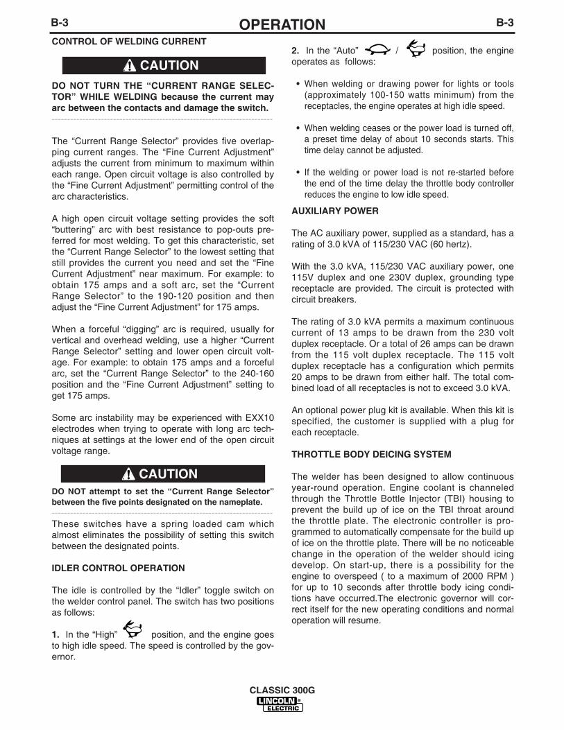
The idle is controlled by the “Idler” toggle switch onthe welder control panel. The switch has two positionsas follows:
1. In the “High” position, and the engine goesto high idle speed. The speed is controlled by the gov-ernor.
2. In the “Auto” / position, the engineoperates as follows:
• When welding or drawing power for lights or tools(approximately 100-150 watts minimum) from thereceptacles, the engine operates at high idle speed.
• When welding ceases or the power load is turned off,a preset time delay of about 10 seconds starts. Thistime delay cannot be adjusted.
• If the welding or power load is not re-started beforethe end of the time delay the throttle body controllerreduces the engine to low idle speed.
CAUTION
CAUTION
C-1ACCESSORIESC-1
CLASSIC 300G
OPTIONAL EQUIPMENT (Field Installed)
Accessory Set (K704) - Includes 35 ft. (10.7m) elec-trode and 30 ft. (9.1m) work cables, headshield, workclamp and electrode holder.
Pipe Thawing with an arc welder can cause fire,explosion, damage to electric wiring or to the arcwelder if done improperly. The use of an arcwelder for pipe thawing is not approved by theCSA, nor is it recommended or supported byLincoln Electric.------------------------------------------------------------------------Power Plug Kit (K802D) - A 20 amp power plug kitfor the auxiliary power receptacles is available.(Provides a plug for each receptacle.)
Remote Control Kit (K924-4) - Contains switch,receptacle, remote control rheostat, and 100 ft(30.5m) cable for adjusting the OCV at the weldingsite.
Trailer (K953-1) - Two-wheeled trailer with optionalfender and light package. For highway use, consultapplicable federal, state, and local laws regardingpossible additional requirements. Their is a choice of2 hitches, a fender & a light package. Order:K953-1 TrailerK958-1 Ball HitchK958-2 Lunette Eye Hitch K959-1 Fender & Light Kit.K965-1 Cable Storage Rack
Remote Control Kit (K924-5) - Contains a remotecontrol rheostat, and 100 ft. (30.5m) cable for adjust-ing the OCV at the welding site.
Remote Control Kit (K2464-1) - Contains a remotecontrol rheostat (for adjusting the CC “STICK” OCV),remote control potentiometer (for adjusting the CV“WIRE” OCV), and 100ft.(30.5m) cable.
Wire Feed Module (K623-1) - Provides constantvoltage (CV) output with improved arc stability forInnershield welding. Excellent for MIG welding.Recommended wire feeders are the LN-7, LN-23Pand LN-25.
GFCI Receptacle Kit (K1690-1) - Includes one ULapproved 115V ground fault circuit interrupter duplextype receptacle and installation instructions. Replacesthe factory installed 115V duplex receptacle. Eachreceptacle of the GFCI duplex is rated at 20 amps.Maximum total current from the GFCI duplex is limitedto 20 amps.
TIG Module - Portable, high frequency unit with gasvalve for TIG welding. Rated at 300 amps / 60% dutycycle. (Request Publication E3.205).Order K930-2
Control Cable - Connects TIG Module to the Classic300G.Order K936-4
Arc Start Switch - Provides on/off control at the TIGModule.Order K814
Contactor Kit - For use with TIG Module.Order K938-1
Control Cable Extension - Allows the TIG Module tobe operated at distances up to 200 ft. from the powersource. Availiable length: 45 ft. (13.7m).Order K937-45
Water Valve Kit - For use with a water-cooled TIGTorch. Installs inside of TIG Module.Order K844-1
K2261-1 OIL DRAIN KIT - Includes ball valve, hoseand clamp.
WARNING
D-1MAINTENANCED-1
SAFETY PRECAUTIONS
GENERAL INSTRUCTIONS
• Blow out the welder and controls with an air hose atleast once every two months. In particularly dirtylocations, this cleaning may be necessary once aweek. Use low pressure air to avoid driving dirt intothe insulation.
• ”Current Range Selector” contacts should not begreased. To keep the contacts clean, rotate the cur-rent control through its entire range frequently.Good practice is to turn the handle from maximumto minimum setting twice each morning before start-ing to weld.
• Put a drop of oil on the “Current Range Selector”shaft at least once every month.
• When necessary, remove the sediment bowl, if soequipped, from beneath the fuel tank and clean outany accumulated dirt and water.
• Follow the engine service schedule in this manualand the detailed maintenance and troubleshooting inthe engine manufacturer’s manual.
COOLING SYSTEM
The Classic 300G is equipped with a pressure radia-tor. Keep the radiator cap tight to prevent loss ofcoolant. Clean and flush the cooling system periodi-cally to prevent clogging the passage and overheatingthe engine. When antifreeze is needed, always usethe permanent type. Capacity = 9.9 qts (9.4 Ltrs.).
BEARINGS
This welder is equipped with a double-shielded ballbearing having sufficient grease to last indefinitelyunder normal service. Where the welder is used con-stantly or in excessively dirty locations, it may be nec-essary to add one half ounce of grease per year. Apad of grease one inch wide, one inch long, and oneinch high weighs approximately one half ounce. Over-greasing is far worse than insufficient greasing.
When greasing the bearings, keep all dirt out of thearea. Wipe the fittings completely clean and use cleanequipment. More bearing failures are caused by dirtintroduced during greasing than from insufficientgrease.
COMMUTATOR AND BRUSHES
Uncovered rotating equipment can be dangerous.Use care so your hands, hair, clothing or tools donot catch in the rotating parts. Protect yourselffrom particles that may be thrown out by the rotat-ing armature when stoning the commutator.------------------------------------------------------------------------Shifting of the commutator brushes may result in:
- Change in machine output- Commutator damage- Excessive brush wear
Periodically inspect the commutator, slip rings, andbrushes by removing the covers. DO NOT remove orreplace these covers while the machine is running.Commutators and slip rings require little attention.However, if they are black or appear uneven, havethem cleaned by an experienced maintenance man using fine sandpaper or a commutator stone. Neveruse emery cloth or paper for this purpose.
CLASSIC 300G
Have qualified personnel do the maintenancework. Turn the engine off before working insidethe machine. In some cases, it may be neces-sary to remove safety guards to performrequired maintenance. Remove guards onlywhen necessary and replace them when themaintenance requiring their removal is com-plete. Always use the greatest care when work-ing near moving parts.
Do not put your hands near the engine coolingblower fan. If a problem cannot be corrected byfollowing the instructions, take the machine tothe nearest Lincoln Field Service Shop.
-----------------------------------------------------------------------ELECTRIC SHOCK can kill.• Do not touch electrically live parts or
electrode with skin or wet clothing.• Insulate yourself from work and
ground• Always wear dry insulating gloves.
------------------------------------------------------------------------ENGINE EXHAUST can kill.• Use in open, well ventilated areas or
vent exhaust outside.
------------------------------------------------------------------------MOVING PARTS can injure.• Do not operate with doors open or
guards off.• Stop engine before servicing.• Keep away from moving parts.
------------------------------------------------------------------------See additional warning information atfront of this operator’s manual.
-----------------------------------------------------------
WARNING
WARNING

D-2MAINTENANCED-2
Replace brushes when they wear within 1/4” of thepigtail. A complete set of replacement brushes shouldbe kept on hand. Lincoln brushes have a curved faceto fit the commutator. Have an experienced mainte-nance man seat these brushes by lightly stoning thecommutator as the armature rotates at full speed untilcontact is made across the full face of the brushes.After stoning, blow out the dust with low pressure air.
To seat slip ring brushes, position the brushes inplace. Then slide one end of a piece of fine sandpaperbetween slip rings and brushes with the coarse sideagainst the brushes. With slight additional finger pres-sure on top of the brushes, pull the sandpaper aroundthe circumference of the rings - in direction of rotationonly - until brushes seat properly. In addition, stoneslip ring with a fine stone. Brushes must be seated100%.
Arcing or excessive exciter brush wear indicates apossible misaligned shaft. Have an authorized FieldService Shop check and realign the shaft.
IDLER CONTROL MAINTENANCE
Before doing electrical work, disconnect the bat-tery.------------------------------------------------------------------------When installing a new battery or using a jumper bat-tery to start the engine, be sure the battery polarity isconnected properly. The correct polarity is negativeground. Damage to the engine alternator and the TBIcontroller can result from incorrect connection.
• Proper operation of the idle control requires goodgrounding of the TBI controller, and battery.
• If desired, the welder can be used without automaticidling by setting the “Idler” switch to the “High”position.
NAMEPLATES
Whenever routine maintenance is performed on thismachine - or at least yearly - inspect all nameplatesand labels for legibility. Replace those which are nolonger clear. Refer to the parts list for the replacementitem number.
PURGING AIR FROM FUEL SYSTEM ( GM3.0L ENGINE)
Keep fuel clear of open flames or arcs, allowengine to cool before working on the fuel system.Wipe up any spilled fuel and do not start engineuntil fumes clear.------------------------------------------------------------------------The fuel system operates as follows, The fuel pumpwill operate for a maximum of 3 seconds when theignition switch is turned “ON”. The pump will restartonce the start button is pushed and continue when theengine starts. To purge the system of air if fuel lineshave been removed, the ignition switch can be tog-gled “ON” and “OFF” (at 3 second intervals) until fuelflows through the fuel return line in the neck of thetank.
The GM 3.0L engine does not require the system tobe bled. If the engine runs out of fuel and the tank isrefilled, the engine will restart within a few seconds ifthe engine is properly tuned.
ENGINE MAINTENANCE
Refer to the engine operation and maintenance man-ual for additional information on the engine.
CLASSIC 300G
CAUTION
WARNING
D-3D-3
CLASSIC 300G
MAINTENANCE
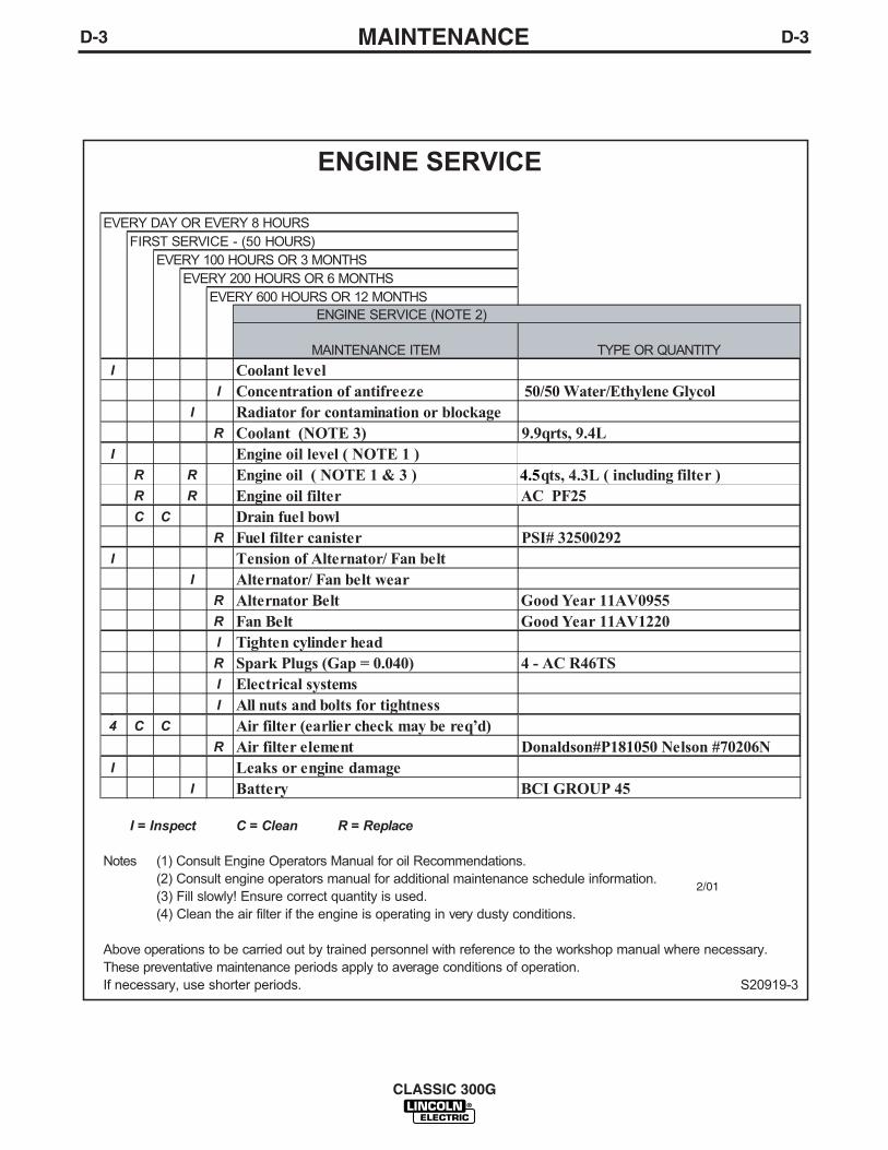
ENGINE SERVICE
EVERY DAY OR EVERY 8 HOURSFIRST SERVICE - (50 HOURS)
EVERY 100 HOURS OR 3 MONTHSEVERY 200 HOURS OR 6 MONTHS
EVERY 600 HOURS OR 12 MONTHS ENGINE SERVICE (NOTE 2)
MAINTENANCE ITEM TYPE OR QUANTITYI Coolant level
I Conc 50/50 Water/Ethylene Glycolentration of antifreezeI Radiator for contamination or blockage
R Coolant (NOTE 3) 9.9qrts, 9.4LI Engine oil level ( NOTE 1 )
R R Engine oil ( NOTE 1 & 3 ) 4.5qts, 4.3L ( including filter )R R Engine oil filter AC PF25C C Drain fuel bowl
R Fuel filter canister PSI# 32500292I Tension of Alternator/ Fan belt
I Alternator/ Fan belt wearR Alternator Belt Good Year 11AV0955R Fan Belt Good Year 11AV1220I Tighten cylinder headR Spark Plugs (Gap = 0.040) 4 - AC R46TSI Electrical systemsI All nuts and bolts for tightness(
4 C C Air filter (earlier check may be req’d)R Air filter element Donaldson#P181050 Nelson #70206N
I Leaks or engine damageI Battery BCI GROUP 45
I = Inspect C = Clean R = Replace
Notes (1) Consult Engine Operators Manual for oil Recommendations.(2) Consult engine operators manual for additional maintenance schedule information.(3) Fill slowly! Ensure correct quantity is used.(4) Clean the air filter if the engine is operating in very dusty conditions.
Above operations to be carried out by trained personnel with reference to the workshop manual where necessary.These preventative maintenance periods apply to average conditions of operation.If necessary, use shorter periods. S20919-3
2/01
E-1TROUBLESHOOTING
CLASSIC 300G
E-1
If for any reason you do not understand the test procedures or are unable to perform the tests/repairs safely, contact yourLocal Lincoln Authorized Field Service Facility for technical troubleshooting assistance before you proceed.
CAUTION
ELECTRIC SHOCK can kill.• Do not touch electrically live parts such as output
terminals or internal wiring.
ENGINE EXHAUST can kill.• Use in open, well ventilated areas or vent exhaust
outside.
MOVING PARTS can injure.• Do not operate with doors open or guards off.• Stop engine before servicing.• Keep away from moving parts.
• Remove guards only when necessary and replace when workrequiring removal is complete.
• Only qualified personnel should install, use or service thisequipment.
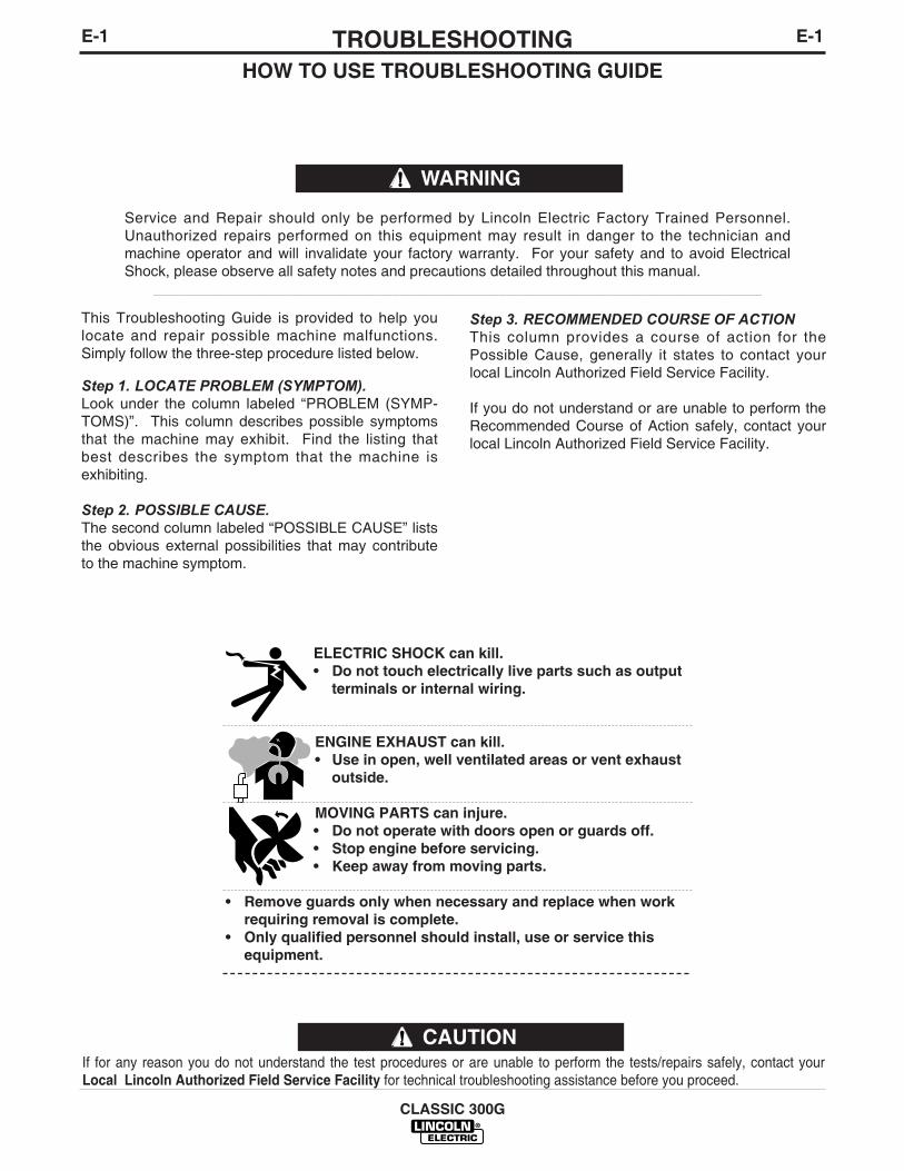
This Troubleshooting Guide is provided to help youlocate and repair possible machine malfunctions.Simply follow the three-step procedure listed below.
Step 1. LOCATE PROBLEM (SYMPTOM).Look under the column labeled “PROBLEM (SYMP-TOMS)”. This column describes possible symptomsthat the machine may exhibit. Find the listing thatbest describes the symptom that the machine isexhibiting.
Step 2. POSSIBLE CAUSE.The second column labeled “POSSIBLE CAUSE” liststhe obvious external possibilities that may contributeto the machine symptom.
Step 3. RECOMMENDED COURSE OF ACTIONThis column provides a course of action for thePossible Cause, generally it states to contact yourlocal Lincoln Authorized Field Service Facility.
If you do not understand or are unable to perform theRecommended Course of Action safely, contact yourlocal Lincoln Authorized Field Service Facility.
HOW TO USE TROUBLESHOOTING GUIDE
Service and Repair should only be performed by Lincoln Electric Factory Trained Personnel.Unauthorized repairs performed on this equipment may result in danger to the technician andmachine operator and will invalidate your factory warranty. For your safety and to avoid ElectricalShock, please observe all safety notes and precautions detailed throughout this manual.
__________________________________________________________________________
WARNING

E-2TROUBLESHOOTING
CLASSIC 300G
E-2
Observe all Safety Guidelines detailed throughout this manual
If for any reason you do not understand the test procedures or are unable to perform the tests/repairs safely, contact yourLocal Lincoln Authorized Field Service Facility for technical troubleshooting assistance before you proceed.
CAUTION
PROBLEMS
PROBLEMS(SYMPTOMS)
POSSIBLECAUSES
RECOMMENDEDCOURSE OF ACTION
Machine fails to hold the heat con-stantly.
Welder starts but fails to generatecurrent.
Welding arc is loud and spattersexcessively.
1. Rough or dirty commutator.
2. Brushes may be worn down tolimit.
3. Field circuit may have variableresistance connection or intermit-tent open circuit due to loose, orbroken wire.
4. Electrode lead or work lead con-nection may be poor.
5. Wrong grade of brushes mayhave been installed on generator.
6. Field rheostat may be makingpoor contact and overheating.
1. Generator or exciter brushes maybe loose or missing.
2. Exciter may not be operating.
3. Field circuit of generator orexciter may be open.
4. Exciter may have lost excitation.
5. Series field and armature circuitmay be open-circuited.
1. Current setting may be too high.
2. Polarity may be wrong.
If all recommended possible areasof misadjustment have beenchecked and the problem persists,Contact your local LincolnAuthorized Field Service Facility.
E-3TROUBLESHOOTINGE-3
CLASSIC 300G
Observe all Safety Guidelines detailed throughout this manual
If for any reason you do not understand the test procedures or are unable to perform the tests/repairs safely, contact yourLocal Lincoln Authorized Field Service Facility for technical troubleshooting assistance before you proceed.
CAUTION
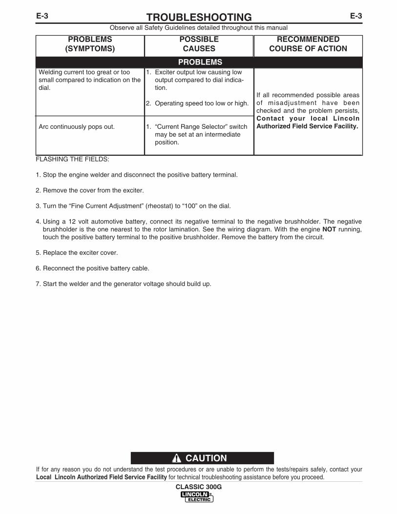
FLASHING THE FIELDS:
1. Stop the engine welder and disconnect the positive battery terminal.
2. Remove the cover from the exciter.
3. Turn the “Fine Current Adjustment” (rheostat) to “100” on the dial.
4. Using a 12 volt automotive battery, connect its negative terminal to the negative brushholder. The negativebrushholder is the one nearest to the rotor lamination. See the wiring diagram. With the engine NOT running,touch the positive battery terminal to the positive brushholder. Remove the battery from the circuit.
5. Replace the exciter cover.
6. Reconnect the positive battery cable.
7. Start the welder and the generator voltage should build up.
PROBLEMS
PROBLEMS(SYMPTOMS)
POSSIBLECAUSES
RECOMMENDEDCOURSE OF ACTION
Welding current too great or toosmall compared to indication on thedial.
Arc continuously pops out.
1. Exciter output low causing lowoutput compared to dial indica-tion.
2. Operating speed too low or high.
1. “Current Range Selector” switchmay be set at an intermediateposition.
If all recommended possible areasof misadjustment have beenchecked and the problem persists,Contact your local LincolnAuthorized Field Service Facility.
E-4TROUBLESHOOTING
CLASSIC 300G
E-4
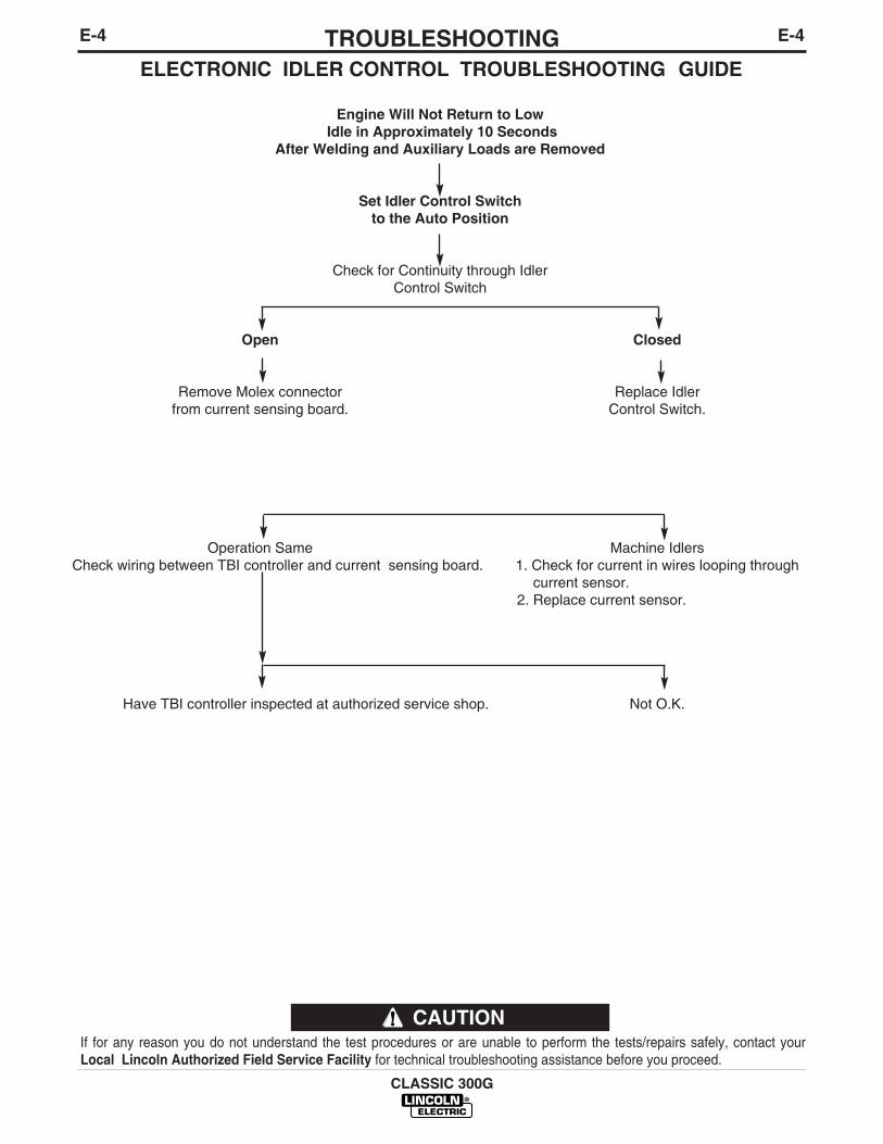
ELECTRONIC IDLER CONTROL TROUBLESHOOTING GUIDE
Engine Will Not Return to Low Idle in Approximately 10 Seconds
After Welding and Auxiliary Loads are Removed
Set Idler Control Switchto the Auto Position
Check for Continuity through IdlerControl Switch
Open Closed
Remove Molex connector Replace Idlerfrom current sensing board. Control Switch.
Operation Same Machine IdlersCheck wiring between TBI controller and current sensing board. 1. Check for current in wires looping through
current sensor.2. Replace current sensor.
Have TBI controller inspected at authorized service shop. Not O.K.
If for any reason you do not understand the test procedures or are unable to perform the tests/repairs safely, contact yourLocal Lincoln Authorized Field Service Facility for technical troubleshooting assistance before you proceed.
CAUTION

E-5TROUBLESHOOTING
CLASSIC 300G
E-5
ELECTRONIC IDLER CONTROL TROUBLESHOOTING GUIDE
With Idler Control Switch in the AUTO Position,Engine Will Not Pick Up Speed When:
Auxiliary Load
1. Load too small. Try loadabove 150 Watts.
2. Check for loose ordisconnected wire runningfrom black lead out of exciterto CB2 circuit breaker.
The Arc is Struck
Check for loose or disconnectedwire running between weldselector switch and output stud.
If for any reason you do not understand the test procedures or are unable to perform the tests/repairs safely, contact yourLocal Lincoln Authorized Field Service Facility for technical troubleshooting assistance before you proceed.
CAUTION
Both
1. Check Idler circuit wiring. Possibleproblems are wires from CurrentSensing Board reversed at idlerswitch or wires connected incorrectlyat Current Sensor Molex plug.
2. Replace current Sensing Board.
E-6TROUBLESHOOTING
CLASSIC 300G
E-6
If for any reason you do not understand the test procedures or are unable to perform the tests/repairs safely, contact yourLocal Lincoln Authorized Field Service Facility for technical troubleshooting assistance before you proceed.
CAUTION
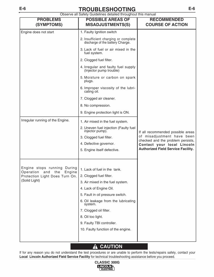
PROBLEMS(SYMPTOMS)
POSSIBLE AREAS OFMISADJUSTMENTS(S)
RECOMMENDEDCOURSE OF ACTION
Engine does not start
Irregular running of the Engine.
Engine stops running DuringOperation and the EngineProtection Light Does Turn On.(Solid Light)
1. Faulty Ignition switch
2. Insufficient charging or completedischarge of the battery Charge.
3. Lack of fuel or air mixed in thefuel system.
2. Clogged fuel filter.
4. Irregular and faulty fuel supply(Injector pump trouble)
5. Moisture or carbon on sparkplugs.
6. Improper viscosity of the lubri-cating oil.
7. Clogged air cleaner.
8. No compression.
9. Engine protection light is ON.
1. Air mixed in the fuel system.
2. Uneven fuel injection (Faulty fuelinjector pump).
3. Clogged fuel filter.
4. Defective governor.
5. Engine itself defective.
1. Lack of fuel in the tank.
2. Clogged fuel filter.
3. Air mixed in the fuel system.
4. Lack of Engine Oil.
5. Fault in oil pressure switch.
6. Oil leakage from the lubricatingsystem.
7. Clogged oil filter.
8. Oil too light.
9. Faulty TBI controller.
10. Faulty function of the engine.
If all recommended possible areasof misadjustment have beenchecked and the problem persists,Contact your local LincolnAuthorized Field Service Facility.
Observe all Safety Guidelines detailed throughout this manual
E-7TROUBLESHOOTING
CLASSIC 300G
E-7
If for any reason you do not understand the test procedures or are unable to perform the tests/repairs safely, contact yourLocal Lincoln Authorized Field Service Facility for technical troubleshooting assistance before you proceed.
CAUTION
Observe all Safety Guidelines detailed throughout this manual
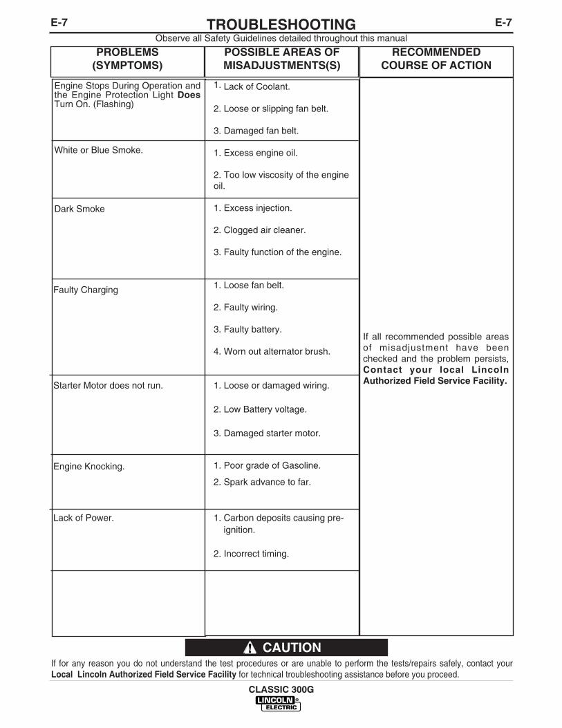
PROBLEMS(SYMPTOMS)
POSSIBLE AREAS OFMISADJUSTMENTS(S)
RECOMMENDEDCOURSE OF ACTION
Engine Stops During Operation andthe Engine Protection Light DoesTurn On. (Flashing)
White or Blue Smoke.
Dark Smoke
Faulty Charging
Starter Motor does not run.
Engine Knocking.
Lack of Power.
1. Lack of Coolant.
2. Loose or slipping fan belt.
3. Damaged fan belt.
1. Excess engine oil.
2. Too low viscosity of the engineoil.
1. Excess injection.
2. Clogged air cleaner.
3. Faulty function of the engine.
1. Loose fan belt.
2. Faulty wiring.
3. Faulty battery.
4. Worn out alternator brush.
1. Loose or damaged wiring.
2. Low Battery voltage.
3. Damaged starter motor.
1. Poor grade of Gasoline.
2. Spark advance to far.
1. Carbon deposits causing pre-ignition.
2. Incorrect timing.
If all recommended possible areasof misadjustment have beenchecked and the problem persists,Contact your local LincolnAuthorized Field Service Facility.

E-8TROUBLESHOOTINGE-8
CLASSIC 300G
Observe all Safety Guidelines detailed throughout this manual
If for any reason you do not understand the test procedures or are unable to perform the tests/repairs safely, contact yourLocal Lincoln Authorized Field Service Facility for technical troubleshooting assistance before you proceed.
CAUTION
PROBLEMS(SYMPTOMS)
POSSIBLE AREAS OFMISADJUSTMENTS(S)
RECOMMENDEDCOURSE OF ACTION
Surging
Large Decrease in Speed.
Engine runs Irregularly.
Engine fails to pick up speed whenArc is struck.
1. Dirty Air Filter.
2. Engine running at RPM limiter(2000 RPM).
1. Ice build up on throttle plate.
1. Faulty coolant temperaturesender.
1. Faulty idler circuit.
If all recommended possible areasof misadjustment have beenchecked and the problem persists,Contact your local LincolnAuthorized Field Service Facility.
F-1DIAGRAMSF-1
CLASSIC 300G
NO
TE
: T
his
dia
gra
m is
fo
r re
fere
nce
onl
y.
It m
ay n
ot
be
accu
rate
fo
r al
l mac
hine
s co
vere
d b
y th
is m
anua
l. T
he s
pec
ific
dia
gra
m f
or
a p
artic
ular
co
de
is p
aste
d in
sid
eth
e m
achi
ne o
n o
ne o
f th
e en
clo
sure
pan
els.
If
the
dia
gra
m is
ille
gib
le, w
rite
to
the
Ser
vice
Dep
artm
ent
for
a re
pla
cem
ent.
Giv
e th
e eq
uip
men
t co
de
num
ber
..
CO
NTR
OL
PAN
EL C
OM
PON
ENTS
B
R
+-
+
-
Y
R W B
B
SLIP
RIN
GS
TO IR
ON
A
54
32
1
ALTE
RNAT
OR
AUXI
LIAR
YPO
WER
WIN
DIN
GS
CB3
CB1
115
VOLT
REC
EPTA
CLE
230
VOLT
REC
EPTA
CLE
Y
NEG
ATIV
E
SELE
CTO
RSW
ITCH
WEL
DER
LEAD
BLO
CK
ACAC
42 602A
G
U
CB2
CB4
F
USE
15A
12
34
56
78
910
1112
1 2 3 4 5 6
600A41
GEN
ERAT
OR
N
-W+Y
G
G
B
600B
610
610
602B
+
84
ALTE
RN
ATO
RRO
TOR
SLIP
RIN
GN
EARE
ST
-
J5
P9J8
POSI
TIVE
ELEC
TRIC
AL S
YMBO
LS
LEAD
CO
LOR
CO
DE
P10
+Y-W
NU
WB
51
60
RHEO
STAT
EXC
+
70
(CC
-)(C
C+)
& (C
V+ W
ITH
W.F
.M.)
SB
Y
B
SEE
BELO
W*
W
G
PLUG
FO
RR
EMO
TE C
ON
TRO
LPO
TEN
TIO
MET
ER
B
*
P81 2 3 4 5 6
X
41 600
42 602
W
RBE
LOW
SEE
*
SWIT
CH
FO
R L
OC
AL O
R R
EMO
TE C
ON
TRO
LSH
OW
N IN
LO
CAL
POSI
TIO
N.
REM
OTE
CO
NTR
OL
REC
EPTA
CLE
& S
WIT
CH
XY
#2 H
EAVY
LEA
D
WIR
E FE
ED M
ODU
LE (O
PTIO
NAL)
WIR
EFE
ED
MO
DU
LE
W.F
.M.
CO
NTR
OL
PANE
L
NEG
.
POS.
OU
TPU
T TE
RM
INAL
SC
ON
NEC
T TO
PO
S. &
NEG
.
CO
NN
ECT
TO N
EG.
BRU
SH H
OLD
ER
608
609
#2 H
EAVY
LEA
D
#8 L
EAD
NEG
ATIV
E C
VO
UTP
UT
TER
MIN
ALPA
NEL
MAC
HINE
MUS
T NO
T BE
RUN
NING
WHE
N M
AKIN
G T
HESE
CO
NNEC
TIO
NS.
ON
MAC
HIN
E, R
EMO
VE P
LUG
"P10
" FR
OM
CO
NN
ECTO
R "J
5".
CO
NN
ECT
PLU
G "P
5" O
N W
.F.M
. TO
CO
NN
ECTO
R "J
5" O
N M
ACH
INE.
PLU
G(P
5)
250
AMP
THER
MO
STAT
ASSE
MBL
Y
INLI
NE
CO
NN
ECTO
RS
REM
OTE
CO
NTR
OL
POTE
NTIO
MET
ER B
OX
L111
94
+
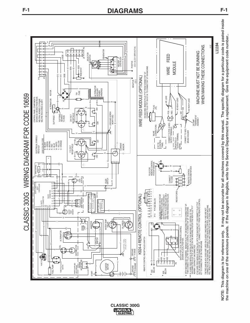
CLAS
SIC
300G
W
IRIN
G D
IAG
RAM
FO
R CO
DE 1
0659
GR
OU
ND
TO B
ASE
GRO
UND
TO E
NG
INE
B
B
B
SHO
WN
AS
VIEW
ED F
RO
M R
EAR
.
CO
NN
ECT
TO C
ASE
G
'N
EUTR
AL B
ON
DED
TO
FR
AME
NEU
TRE
RAC
CO
RD
E AU
BAT
I
(GR
OU
ND
SC
REW
NEA
R FU
SE)
A.02
3 4 5 14
61
62
K924
-4 R
EMO
TE C
ONT
ROL
(OPT
IONA
L)
WIT
H M
ACH
INE
NO
T R
UN
NIN
G,
REM
OVE
PLU
G "P
9" O
N M
ACH
INE
FRO
M C
ON
NEC
TOR
"J8"
.TH
EN C
ON
NEC
T PL
UG
"P8"
ON
REM
OTE
CO
NTR
OL
TO C
ON
NEC
TOR
"J8"
ON
MAC
HIN
E.
CAU
TIO
N: D
AMAG
E C
AN O
CC
UR
TO T
HE
REM
OTE
CO
NTR
OL
SWIT
CH
IF IT
IS U
SED
WIT
HO
UT
THE
"P11
" PLU
G IN
STAL
LED
OR
AW
IRE
FEED
MO
DU
LE IN
STAL
LED
.
IF
A W
IRE
FEED
MO
DU
LE IS
INST
ALLE
D, W
ITH
TH
E M
ACH
INE
OFF
, DIS
POSE
OF
THE
UN
CO
NN
ECTE
D P
LUG
"P10
" (IF
ON
E IS
ON
TH
E M
ACH
INE)
FAS
TEN
TH
E N
EW P
LUG
"P11
" N
EAR
BY, L
EAVI
NG
IT U
NC
ON
NEC
TED
.IF
NO
WIR
E FE
ED M
OD
ULE
IS IN
STAL
LED
, WIT
H T
HE
MAC
HIN
E O
FF, D
ISC
ON
NEC
T PL
UG
"P10
"O
N T
HE
MAC
HIN
E FR
OM
CO
NN
ECTO
R "J
5".
CO
NN
ECT
PLU
G "P
11" F
RO
M T
HE
REM
OTE
CO
NTR
OL
KIT
TO C
ON
NEC
TOR
"J5"
ON
TH
E M
ACH
INE.
SE
E BE
LOW
15 19
ZENI
TH T
HRO
TTLE
BOD
YC
ONT
ROLL
ER
* *
**
PER
E153
7
B - B
LAC
KG
- G
REE
NN
- BR
OW
NR
- R
EDU
- BL
UE
W -
WH
ITE
Y - Y
ELLO
W
THE
RED
AN
D B
LAC
K LE
ADS
ARE
USE
D O
N C
LASS
IC I
MAC
HIN
ES O
NLY
AN
D A
RE
NO
TC
ON
NEC
TED
ON
TH
IS M
ACH
INE.
DAM
AGE
TO T
HE
REM
OTE
CO
NTR
OL
AND
/OR
MAC
HIN
EW
ILL
RES
ULT
IF T
HE
RED
AN
D B
LAC
K LE
ADS
ARE
CO
NN
ECTE
D IN
TH
E C
LASS
IC 3
00G
.
71
72
82
81
76
74
73
83
99E
78
9980
89
B
CU
RR
ENT
SEN
SOR
3 2 14
21 22+
-
-
WH
ITE
CO
NN
ECTO
R
BLAC
KC
ON
NEC
TOR 11
98
54
31
1713
-+
96
99D
87A
WAT
ERTE
MP.
SEN
SOR
AB
AIR
TEM
P.SE
NSO
R
95
CB5
AB
C
O -
OR
ANG
E
93
#
INJE
CTO
R
THRO
TTLE
PLA
TEM
OTO
R
AB
92
9190
97
97A
99B
99C
67
2
MAP
SEN
SOR
12
COIL
DIS
TRIB
UTO
R
IDLE
RSW
ITC
H
ALTE
RN
ATO
R
IGN
ITIO
NSW
ITC
H
STAR
TER
MO
TOR
ENG
INE
HO
UR
MET
EREN
GIN
EFA
ILU
RELA
MP
STAR
T
WAT
ER T
EMP.
GAU
GE
S
AB
94
FUEL
PUM
P
77
OIL
PRE
SS.
GAU
GE
S
CONT
ROL
PANE
LGR
OUND
SCR
EW
69
45R
G
87
99A
97B
97C
{R
ES
ISTO
RS
12
34
56
78
910
1112 P
11
5087
B
G
AMM
ETER
SENS
OR
WAT
ER TE
MP. S
ENDE
R
SENS
OR
OIL P
RESS
URE
SWIT
CH &
SEN
SOR
SW
ITC
H
WK
G
PART
S SU
PPLI
ED W
ITH
ENG
INE
12
3
21
34
RPM
CO
NTR
OL
10 K
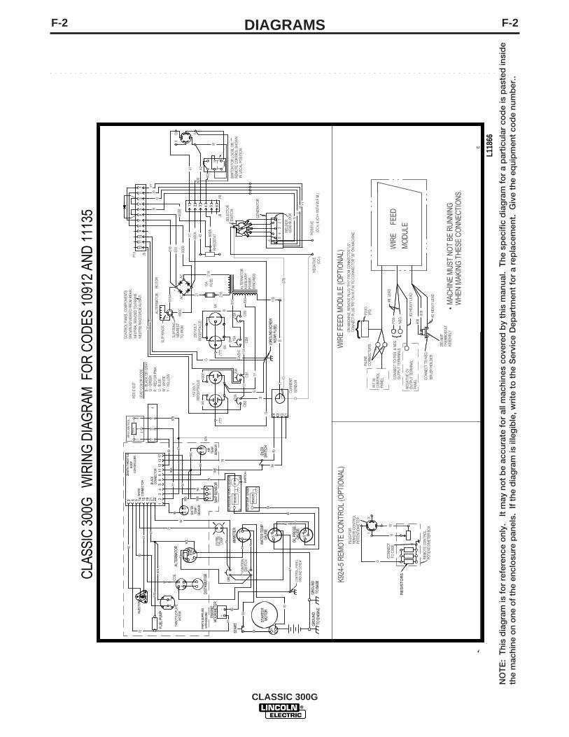
F-2DIAGRAMSF-2
CLASSIC 300G
NO
TE
: T
his
dia
gra
m is
fo
r re
fere
nce
onl
y.
It m
ay n
ot
be
accu
rate
fo
r al
l mac
hine
s co
vere
d b
y th
is m
anua
l. T
he s
pec
ific
dia
gra
m f
or
a p
artic
ular
co
de
is p
aste
d in
sid
eth
e m
achi
ne o
n o
ne o
f th
e en
clo
sure
pan
els.
If
the
dia
gra
m is
ille
gib
le, w
rite
to
the
Ser
vice
Dep
artm
ent
for
a re
pla
cem
ent.
Giv
e th
e eq
uip
men
t co
de
num
ber
..
L118
66
CLA
SSIC
300
G
WIR
ING
DIA
GRA
M F
OR
CO
DES
109
12 A
ND
111
35
C
CO
NTR
OL
PAN
EL C
OM
PON
ENTS
610A
600C
+-
+
-
21A
810 820
11B
B
SLIP
RIN
GS
TO IR
ON
A
54
32
1
ALTE
RNA
TOR
AUXI
LIAR
YPO
WER
WIN
DIN
GS
CB3
CB1
115
VOLT
REC
EPTA
CLE
230
VOLT
REC
EPTA
CLE
21A
NEG
ATIV
E
SELE
CTO
RSW
ITC
H
WEL
DER
LEAD
BLO
CK
ACAC
42 602A
GN
D-E
U
CB2
CB4
F
USE
15A
12
34
56
78
910
11
1 3 4 5 6
600A41
GEN
ERAT
OR
N
-W+Y
G
G
B
600B
610
610
602B
+
84
ALTE
RNA
TOR
RO
TOR
SLIP
RIN
GN
EARE
ST
-
J5
P8J8
POSI
TIVE
LEAD
CO
LOR
CO
DE
P10
+Y-W
NU
WB
51
60
RH
EOST
AT
EXC
+
70
(CC-
)(C
C+)
& (C
V+ W
ITH
W.F
.M.)
SB
Y
W
G
PLU
G F
OR
REM
OTE
CO
NTR
OL
POTE
NTIO
MET
ER
B
X
602
W
SWIT
CH
FO
R L
OC
AL O
R
IN L
OC
AL P
OSI
TIO
N.
XY
#2 H
EAVY
LEA
D
WIR
E FE
ED M
ODU
LE (O
PTIO
NAL
) WIR
EFE
ED
MO
DULE
W.F
.M.
CO
NTR
OL
PANE
L
POS.
OU
TPUT
TER
MIN
ALS
CO
NN
ECT
TO P
OS.
& N
EG.
CO
NN
ECT
TO N
EG.
BRUS
H H
OLD
ER
608
609
#2 H
EAVY
LEA
D
#8 L
EAD
NEG
ATIV
E CV
OU
TPUT
TER
MIN
ALPA
NEL
MAC
HIN
E M
UST
NOT
BE R
UNNI
NG
ON
MAC
HIN
E, R
EMO
VE P
LUG
"P10
" FR
OM
CO
NN
ECTO
R "J
5".
CO
NN
ECT
PLUG
"P5"
ON
W.F
.M. T
O C
ON
NEC
TOR
"J5"
ON
MAC
HIN
E.
PLU
G(P
5)
250
AMP
THER
MO
STAT
ASSE
MBL
Y
INLI
NE
CO
NN
ECTO
RS
REM
OTE
CO
NTR
OL
POTE
NTIO
MET
ER B
OX
+
GR
OU
ND
TO B
ASE
GR
OU
ND
TO E
NGIN
E
4A
B
B
SHO
WN
AS V
IEW
ED F
RO
M R
EAR
.
CO
NN
ECT
TO C
ASE
G
'N
EUTR
AL B
ON
DED
TO
FR
AME
NEU
TRE
RAC
CO
RD
E AU
BAT
I
(GR
OU
ND
SC
REW
NEA
R F
USE
)
3 4 5 14
61
62
15 19
ZENI
TH T
HRO
TTLE
BODY
CO
NTR
OLL
ERPE
R E
1537
B - B
LAC
K O
R G
RAY
G -
GR
EEN
R -
RED
OR
PIN
KU
- BL
UEW
- W
HIT
EY
- YEL
LOW
71
72
82
81
76
74
73
83
99E
78
9980
89
400F
CU
RRE
NTSE
NSO
R
3 2 14
21 22+
-
-
WH
ITE
CO
NNEC
TOR
BLAC
KC
ON
NEC
TOR 11
98
54
31
1713
C.01
+
96
99D
87A
WAT
ERTE
MP.
SENS
OR
AB
AIR
TEM
P.SE
NSO
R
95
CB5
AB
C93
#
INJE
CTO
R
THR
OTT
LE P
LATE
MO
TOR
AB
92
9190
97
97A
99B
99C
67
2
MAP
SEN
SOR
12
CO
IL
DIS
TRIB
UTO
R
IDLE
RSW
ITC
H
ALTE
RNA
TOR
IGN
ITIO
NSW
ITC
H
STAR
TER
MO
TOR
ENG
INE
HO
UR
MET
EREN
GIN
EFA
ILUR
ELA
MP
STAR
T
WAT
ER T
EMP.
GAU
GE
S
AB
94
FUEL
PUM
P
77
OIL
PRE
SS.
GAU
GE
S
CONT
ROL
PANE
LGR
OUND
SCR
EW
69
45R
G
87
99A
97B
97C
{{
RES
ISTO
RS
5087
BG
AMM
ETER
SENS
OR
WAT
ER TE
MP.
SEN
DER
SENS
OR
OIL
PRES
SURE
SW
ITCH
& SE
NSOR
SW
ITC
H
WK
G
PAR
TS S
UPPL
IED
WIT
H E
NG
INE
12
3
21
34
RPM
CO
NTR
OL
10 K
15A
15A
20A
20A
41 4260
0 REM
OTE
CO
NTR
OL
SHO
WN
K924
-5 R
EMO
TE C
ON
TRO
L (O
PTIO
NAL)
WH
EN M
AKIN
G T
HES
E CO
NNE
CTIO
NS.
*
NEG
.
2
12
11
21
6A
6A
67B
11A
11

F-3DIAGRAMSF-3
CLASSIC 300G
S26097 A
RESISTORS
Y X
BG W
FG
ORANGE
WHITE JUMPERWHITE JUMPER
PINCABLE CONNECTION TABLE
CD
ELEAD COLORRED
BLUE
CV "WIRE" CONTROL POTCCW
BLUE
REDORANGE
REMOTE CONTROL BOX CONNECT TO CASE
K2464-1 REMOTE CONTROL WIRING / CONNECTION DIAGRAM
CC "STICK CONTROL
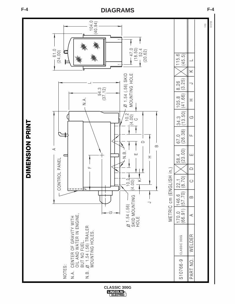
F-4DIAGRAMSF-4
CLASSIC 300G
PA
RT
NO
.W
ELD
ER
AB
CD
EF
GH
S10
766-
9
JK
L
CLA
SS
IC 3
00G
S107
66
1/03
ME
TRIC
cm
(E
NG
LIS
H i
n.)
170.
0(6
6.91
)14
6.6
(57.
70)
22.1
(8.7
0)58
.4(2
3.00
)67
.0(2
6.38
)34
.3(1
3.50
)10
5.8
(41.
66)
8.26
(3.2
5)11
5.6
(45.
5)
AC
ON
TRO
L P
AN
EL
F
G
B
H
D
EC
O HO
LE
O MO
UN
TIN
GH
OLE
N.A
.
N.B
.
NO
TES
: OIL
AN
D W
ATE
R I
N E
NG
INE
,B
UT
NO
FU
EL.
N.A
. C
EN
TER
OF
GR
AV
ITY
WIT
H
O
J
K
DIM
EN
SIO
N P
RIN
T
N.B
.
1
.54
(.56
) TR
AIL
ER
M
OU
NTI
NG
HO
LES
.
94.3
(37.
12)
L
61.0
(24.
00)
104.
0(4
0.94
)
47.0
(18.
50)
52.4
(20.
62)
10.2
(4.0
0)10
.2(4
.00)
1.54
(.5
6) S
KID
1.54
(.5
6)S
KID
MO
UN
TIN
G
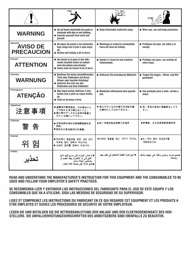
WARNING
AVISO DEPRECAUCION
ATTENTION
WARNUNG
ATENÇÃO
Spanish
French
German
Portuguese
Japanese
Chinese
Korean
Arabic
READ AND UNDERSTAND THE MANUFACTURER’S INSTRUCTION FOR THIS EQUIPMENT AND THE CONSUMABLES TO BEUSED AND FOLLOW YOUR EMPLOYER’S SAFETY PRACTICES.
SE RECOMIENDA LEER Y ENTENDER LAS INSTRUCCIONES DEL FABRICANTE PARA EL USO DE ESTE EQUIPO Y LOSCONSUMIBLES QUE VA A UTILIZAR, SIGA LAS MEDIDAS DE SEGURIDAD DE SU SUPERVISOR.
LISEZ ET COMPRENEZ LES INSTRUCTIONS DU FABRICANT EN CE QUI REGARDE CET EQUIPMENT ET LES PRODUITS AETRE EMPLOYES ET SUIVEZ LES PROCEDURES DE SECURITE DE VOTRE EMPLOYEUR.
LESEN SIE UND BEFOLGEN SIE DIE BETRIEBSANLEITUNG DER ANLAGE UND DEN ELEKTRODENEINSATZ DES HER-STELLERS. DIE UNFALLVERHÜTUNGSVORSCHRIFTEN DES ARBEITGEBERS SIND EBENFALLS ZU BEACHTEN.
● Do not touch electrically live parts orelectrode with skin or wet clothing.
● Insulate yourself from work andground.
● No toque las partes o los electrodosbajo carga con la piel o ropa moja-da.
● Aislese del trabajo y de la tierra.
● Ne laissez ni la peau ni des vête-ments mouillés entrer en contactavec des pièces sous tension.
● Isolez-vous du travail et de la terre.
● Berühren Sie keine stromführendenTeile oder Elektroden mit IhremKörper oder feuchter Kleidung!
● Isolieren Sie sich von denElektroden und dem Erdboden!
● Não toque partes elétricas e elec-trodos com a pele ou roupa molha-da.
● Isole-se da peça e terra.
● Keep flammable materials away.
● Mantenga el material combustiblefuera del área de trabajo.
● Gardez à l’écart de tout matérielinflammable.
● Entfernen Sie brennbarres Material!
● Mantenha inflamáveis bem guarda-dos.
● Wear eye, ear and body protection.
● Protéjase los ojos, los oídos y elcuerpo.
● Protégez vos yeux, vos oreilles etvotre corps.
● Tragen Sie Augen-, Ohren- und Kör-perschutz!
● Use proteção para a vista, ouvido ecorpo.
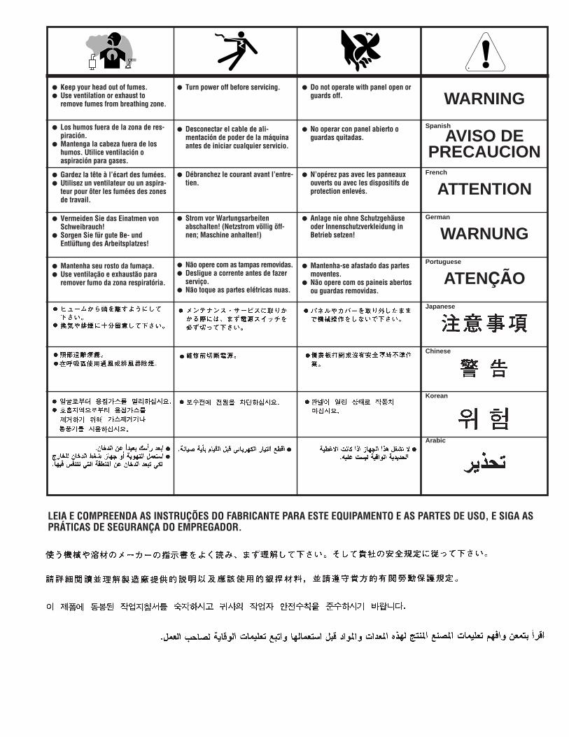
WARNING
AVISO DEPRECAUCION
ATTENTION
WARNUNG
ATENÇÃO
Spanish
French
German
Portuguese
Japanese
Chinese
Korean
Arabic
LEIA E COMPREENDA AS INSTRUÇÕES DO FABRICANTE PARA ESTE EQUIPAMENTO E AS PARTES DE USO, E SIGA ASPRÁTICAS DE SEGURANÇA DO EMPREGADOR.
● Keep your head out of fumes.● Use ventilation or exhaust to
remove fumes from breathing zone.
● Los humos fuera de la zona de res-piración.
● Mantenga la cabeza fuera de loshumos. Utilice ventilación oaspiración para gases.
● Gardez la tête à l’écart des fumées.● Utilisez un ventilateur ou un aspira-
teur pour ôter les fumées des zonesde travail.
● Vermeiden Sie das Einatmen vonSchweibrauch!
● Sorgen Sie für gute Be- undEntlüftung des Arbeitsplatzes!
● Mantenha seu rosto da fumaça.● Use ventilação e exhaustão para
remover fumo da zona respiratória.
● Turn power off before servicing.
● Desconectar el cable de ali-mentación de poder de la máquinaantes de iniciar cualquier servicio.
● Débranchez le courant avant l’entre-tien.
● Strom vor Wartungsarbeitenabschalten! (Netzstrom völlig öff-nen; Maschine anhalten!)
● Não opere com as tampas removidas.● Desligue a corrente antes de fazer
serviço.● Não toque as partes elétricas nuas.
● Do not operate with panel open orguards off.
● No operar con panel abierto oguardas quitadas.
● N’opérez pas avec les panneauxouverts ou avec les dispositifs deprotection enlevés.
● Anlage nie ohne Schutzgehäuseoder Innenschutzverkleidung inBetrieb setzen!
● Mantenha-se afastado das partesmoventes.
● Não opere com os paineis abertosou guardas removidas.

• Sales and Service through Subsidiaries and Distributors Worldwide •
Cleveland, Ohio 44117-1199 U.S.A. TEL: 216.481.8100 FAX: 216.486.1751 WEB SITE: www.lincolnelectric.com
• World's Leader in Welding and Cutting Products •