Embed Size (px)
Citation preview
1SiD, M. Ross (SLAC)
ILC Status
After the Technical Design Phase
Presentation to SiD prepared by:
Marc Ross (SLAC)
October 14, 2013
2SiD, M. Ross (SLAC)
TDP Goals:» R & D to enable Project Proposal and updated Value estimate –
with Cost Containment» Technology Transfer
• development a strong industrial base Technical Design Report:
» Consists of two parts: 1) R & D Report and 2) Design Description Beam Test Facilities:
» SRF Linac: Fermilab NML, DESY E-XFEL and FLASH, KEK STF » Beam Dynamics: Cornell CesrTA (2008 – 2010)» Beam Tuning: KEK ATF2
Production / Industrialization:» CEBAF Upgrade and E-XFEL
Completing the TDP: Outline
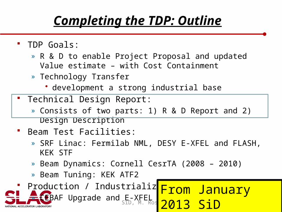
From January 2013 SiD meeting
3SiD, M. Ross (SLAC)
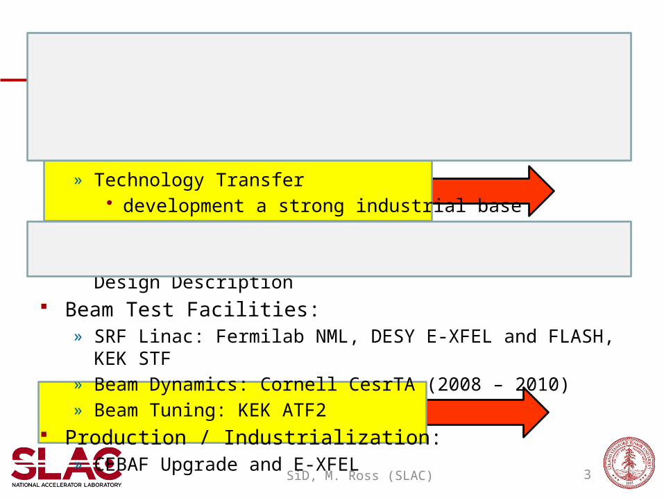
Completing the TDP: Outline
TDP Goals:» R & D to enable Project Proposal and updated Value estimate –
with Cost Containment» Technology Transfer
• development a strong industrial base Technical Design Report:
» Consists of two parts: 1) R & D Report and 2) Design Description Beam Test Facilities:
» SRF Linac: Fermilab NML, DESY E-XFEL and FLASH, KEK STF » Beam Dynamics: Cornell CesrTA (2008 – 2010)» Beam Tuning: KEK ATF2
Production / Industrialization:» CEBAF Upgrade and E-XFEL
4SiD, M. Ross (SLAC)
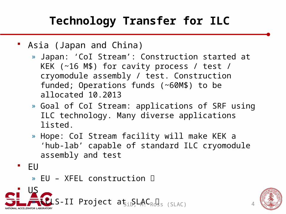
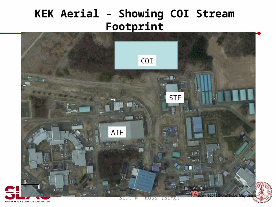
Asia (Japan and China)» Japan: ‘CoI Stream’: Construction started at KEK (~16 M$) for
cavity process / test / cryomodule assembly / test. Construction funded; Operations funds (~60M$) to be allocated 10.2013
» Goal of CoI Stream: applications of SRF using ILC technology. Many diverse applications listed.
» Hope: CoI Stream facility will make KEK a ‘hub-lab’ capable of standard ILC cryomodule assembly and test
EU» EU – XFEL construction
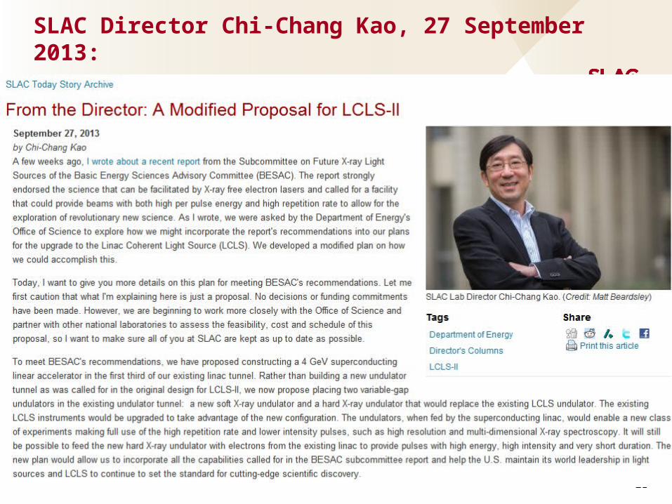
US» LCLS-II Project at SLAC
Technology Transfer for ILC
5SiD, M. Ross (SLAC)
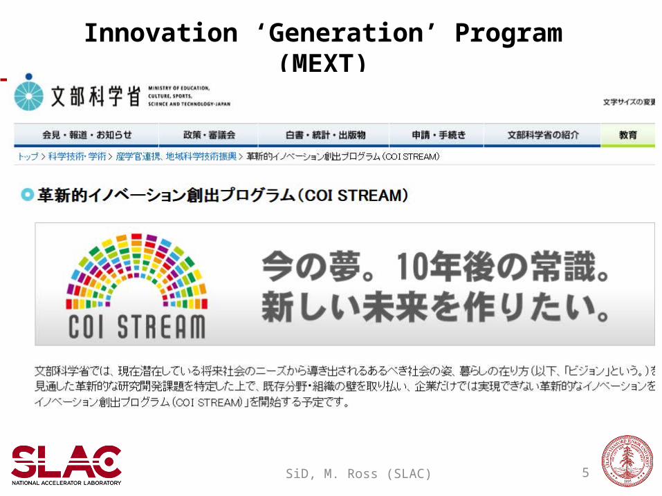
Innovation ‘Generation’ Program (MEXT)
2012 supplementary budget,Industry-University cooperation COI program:
Generation of ‘Earth-Cleaner’ market
地域資源等を活用した産学連携による 国際科学イノベーション拠点整備事業地球を守るアース・クリーナー市場を創出する 新産学連携拠点
Status of COI program 10142013COI : Center Of Innovation
7SiD, M. Ross (SLAC)
KEK Aerial – Showing COI Stream Footprint
ATF
STF
COI
8
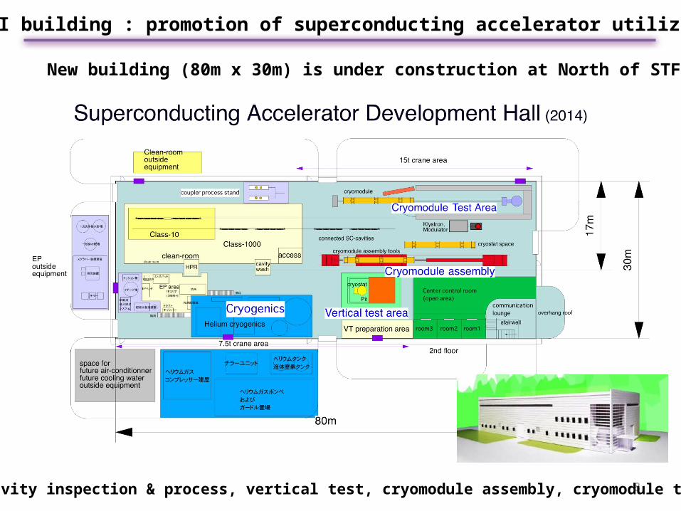
COI building : promotion of superconducting accelerator utilization
New building (80m x 30m) is under construction at North of STF
SC cavity inspection & process, vertical test, cryomodule assembly, cryomodule test
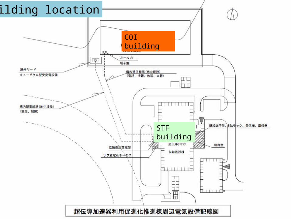
Building location
STF building
COI building
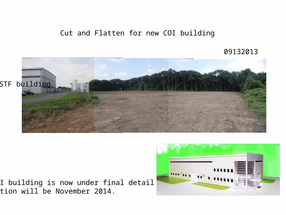
Cut and Flatten for new COI building
09132013
new COI building is now under final detail design,Completion will be November 2014.
STF building
11SiD, M. Ross (SLAC)
Application to EU for ILC-bridging funds under Horizon 2020 FP program» Signs of ‘interest’
Intensive industrialization and production of 1.3 GHz ILC - style SRF technology
Reported at ‘SRF 2013’, Paris 23-27.09.2013
EU Highlights (mostly XFEL)

Comparison of Q0 at 2 Kfor 11 EP-treated LG cavities (red) with
Q0 at 2 K of XFELprototype cavities (AC115–AC129, best
result) treated accordingto XFEL recipe (blue).
12
Eacc performance of LG cavities in EXFEL cryomodule XM-3.
The cryomodule has ca. 60% lower cryogenic losses in CW, compared
to all 4 previously tested cryomodules (J. Sekutowicz). For details see presentation of C.
Madec THIOA02 The Challenge and Realization of the Cavity Production and Treatment in Industry for the European XFEL. SRF 2013. Waldemar Singer
26,1
31,6
40,838,5
31,5
38,1
28,1
33
23,2
31,4
40,838,5
31,5
38,1
22,7
33
AC114 AC156 AC146 AC154 AC157 AC158 AC151 AC152
10
20
30
40
Module
quench limit operating gradient XFEL goal
European XFEL Large Grain Cavities (or LG advertisement for future projects)

E. Zanon: Status September 10th. Delivered 69 CAVs. More details in Talk THIOA01
The Challenge and Realization of the Cavity Production and Treatment in Industry for the European XFEL. SRF 2013. Waldemar Singer

RI: Status September 10th. Delivered 42 CAVs. More details in Talk THIOA01
The Challenge and Realization of the Cavity Production and Treatment in Industry for the European XFEL. SRF 2013. Waldemar Singer
15
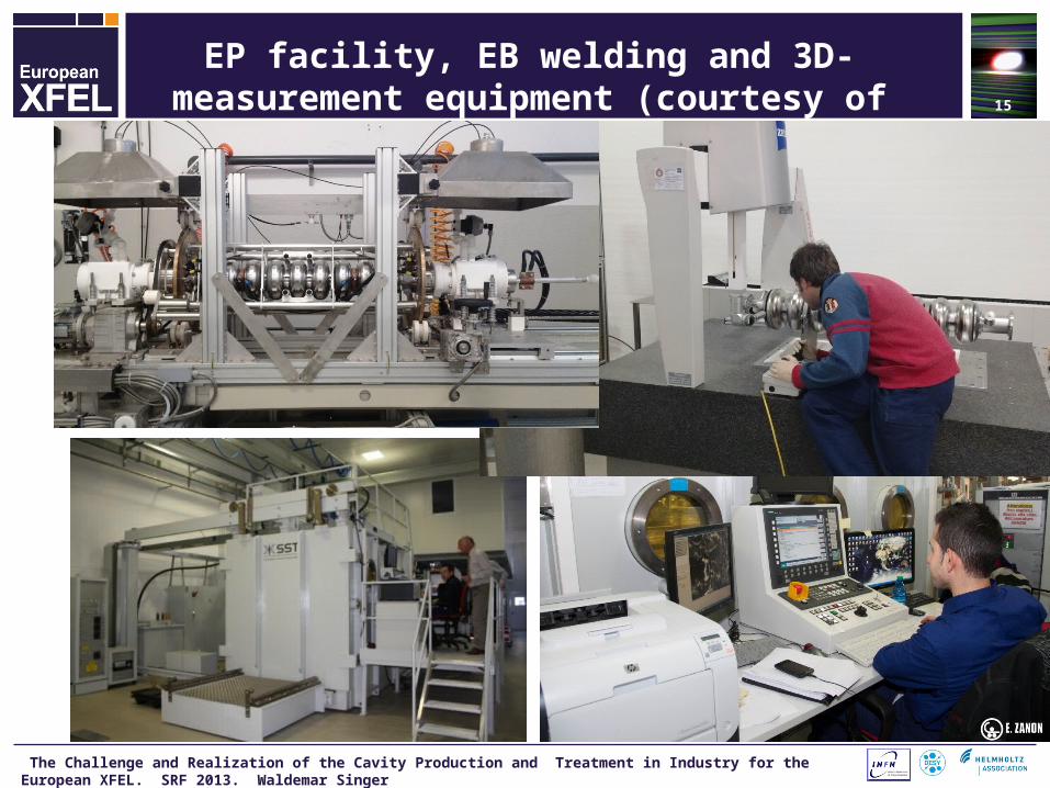
EP facility, EB welding and 3D-measurement equipment (courtesy of E. Zanon)
The Challenge and Realization of the Cavity Production and Treatment in Industry for the European XFEL. SRF 2013. Waldemar Singer
16
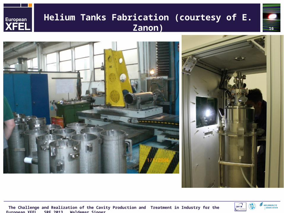
Helium Tanks Fabrication (courtesy of E. Zanon)
The Challenge and Realization of the Cavity Production and Treatment in Industry for the European XFEL. SRF 2013. Waldemar Singer


19SiD, M. Ross (SLAC)
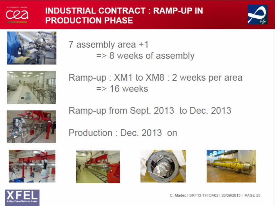
Cavity production lines fully functioning: 8 cavities / week» Two companies
Coupler production quality improved Cryomodule production:
• Three pre-series CM (XM-3, XM-2, XM-1) in process; typical time to construct 4 months; time to test unknown (XM-2 now in cool-down)
• Production series of 81 each started Sep. 02, 2013; full rate from Dec 2013 (until Oct 2, 2015)
• One CM / week; one production line (CEA-Saclay)
24 cavities to be used for high – gradient development
EU - XFEL
20SiD, M. Ross (SLAC)
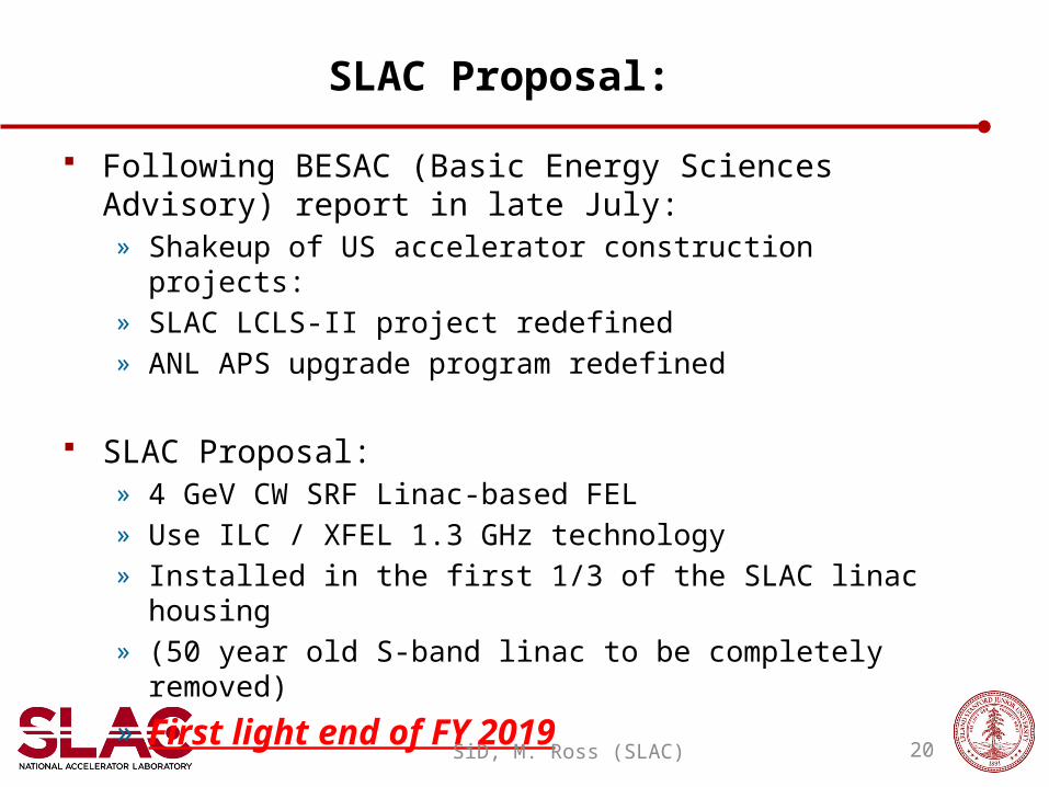
Following BESAC (Basic Energy Sciences Advisory) report in late July:» Shakeup of US accelerator construction projects:» SLAC LCLS-II project redefined» ANL APS upgrade program redefined
SLAC Proposal:» 4 GeV CW SRF Linac-based FEL» Use ILC / XFEL 1.3 GHz technology» Installed in the first 1/3 of the SLAC linac housing» (50 year old S-band linac to be completely removed)
» First light end of FY 2019
SLAC Proposal:
21
SLAC Director Chi-Chang Kao, 27 September 2013:
22
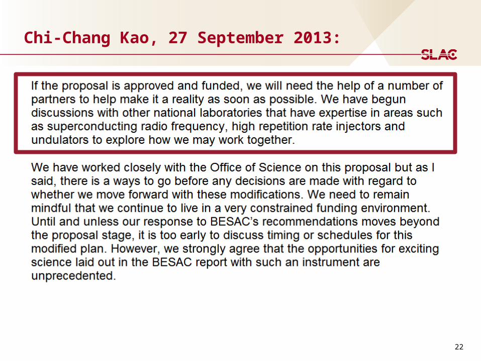
Chi-Chang Kao, 27 September 2013:

23
RF Parameters:
LCLS-II Planning Meeting, Oct 9-11, 2013

24
RF Parameters (2)
LCLS-II Planning Meeting, Oct 9-11, 2013

LCLS-II - Linac and Compressor Layout for 4 GeV
CM01 CM2,3 CM04 CM15 CM16 CM35
BC1270 MeV
R56 = -65 mmIpk = 60 A
Lb = 0.40 mmsd = 1.4 %
BC21550 MeV
R56 = -65 mmIpk = 1000 A
Lb = 0.024 mmsd = 0.50 %
GUN0.75 MeV
LH98 MeV
R56 = -5 mmIpk = 12 A
Lb = 2.0 mmsd = 0.006 %
L0j 0
V0 97 MV
L1j =-26°
V0 =235 MV
HLj =-170°
V0 =40 MV
L2j = -28°
V0 = 1448 MV
L3j = 0
V0 = 2460 MV
LTU4.0 GeVR56 = 0
Ipk = 1000 ALb = 0.024 mm
sd 0.02 %
100 pC; Machine layout 26SEP2013; Bunch length Lb is FWHM
3.9GHz
Linac V(MV)
j(deg)
Acc. Grad.
(MV/m)
No. Cryo Mod’s
No. Cav’s
Spare Cav’s
Cavities per
Amplifier
L0 97 * 14.6 1 8 1 1
L1 235 -26 15.1 2 16 1 ?
HL -40 -170 - 3 (3.9GHz) 12 0 12?
L2 1448 -28 15.5 12 96 6 32?
L3 2460 0 15.7 20 160 10 32?
* L0 phases: (-40, -52, 0, 0, 0, 13, 33), with cav-2 at 20% of other L0 cav’s.
Includes 2-km RW wake
26
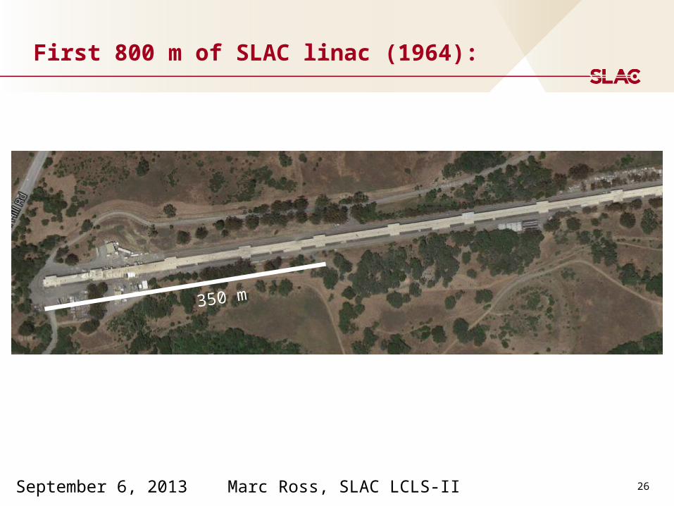
First 800 m of SLAC linac (1964):
350 m
Marc Ross, SLAC LCLS-IISeptember 6, 2013
27
LCLS-II and ILC
Much LCLS-II construction will be done at Fermilab, using
infrastructure intended for ILC
18 CM? (50%)
Other CM to be made at JLab (and Cornell)
US team have made ~ two ILC CM. LCLS-II effort will help
understand US-domestic technical, cost, and
industrialization
28
ILC R & D initiative: Power Coupler development
Mandated by PAC (12.2012) technical review
Issues:
• Cost
• Copper coating / flaking
• Complex Assembly
• Plug-compatibility
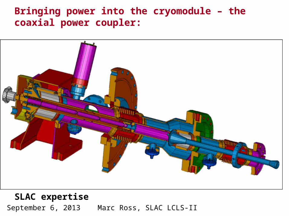
Bringing power into the cryomodule – the coaxial power coupler:
SLAC expertiseMarc Ross, SLAC LCLS-IISeptember 6, 2013
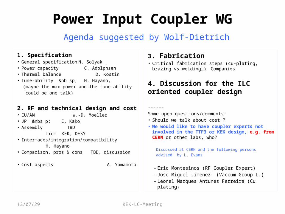
Power Input Coupler WG Agenda suggested by Wolf-Dietrich
1. Specification• General specification N. Solyak • Power capacity C. Adolphsen• Thermal balance D. Kostin• Tune-ability &nb sp; H. Hayano,
(maybe the max power and the tune-ability could be one talk)
2. RF and technical design and cost• EU/AM W.-D. Moeller• JP &nbs p; E. Kako• Assembly TBD
from KEK, DESY• Interfaces/integration/compatibility
H. Hayano• Comparison, pros & cons TBD, discussion
• Cost aspects A. Yamamoto
3. Fabrication• Critical fabrication steps (cu-plating, brazing vs welding…)
Companies
4. Discussion for the ILC oriented coupler design
------Some open questions/comments:• Should we talk about cost ?• We would like to have coupler experts not involved in
the TTF3 or KEK design, e.g. from CERN or other labs, who?
Discussed at CERN and the following persons advised by L. Evans
– Eric Montesinos (RF Coupler Expert)– Jose Miguel Jimenez (Vaccum Group L.)– Leonel Marques Antunes Ferreira (Cu plating)
13/07/29 KEK-LC-Meeting
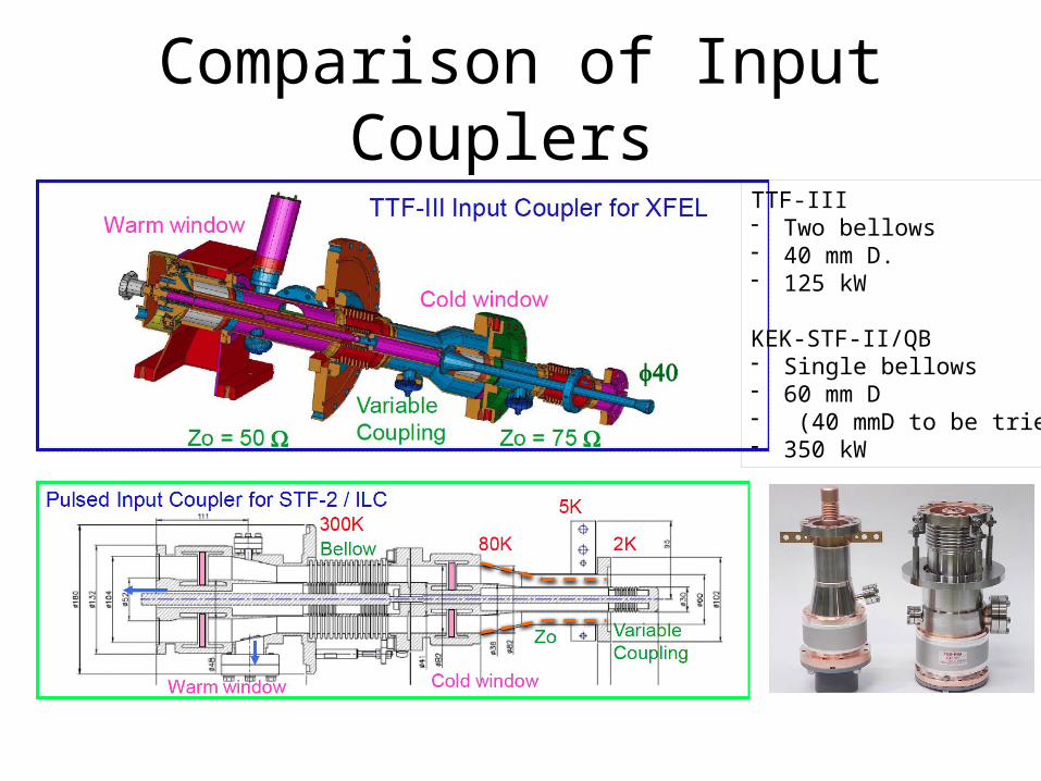
Comparison of Input Couplers TTF-III- Two bellows- 40 mm D. - 125 kW
KEK-STF-II/QB- Single bellows- 60 mm D - (40 mmD to be tried- 350 kW

ATF2 Program Status
Glen White, SLACJanuary 2013
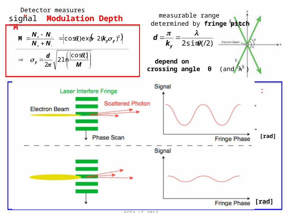
Detector measures signal Modulation Depth “M”
N +
N -
[rad]
[rad]
ECFA LC 2013
measurable range determined by fringe pitch
depend on crossing angle θ (and λ )
N: no. of Compton photonsConvolution between e- beam profile and fringe intensity
)2/sin(2
ykd
M
d
kNN
NN
y
yy
)cos(ln2
2
)(2exp)cos( 2
M
Focused Beam : large M
Dilluted Beam : small M
Small σy
Large σy
13/05/29 33

Crossing angle θ
174° 30° 8° 2°
Fringe pitch 266 nm 1.03 μm 3.81 μm 15.2 μm
Lower limit 20 nm 80 nm 350 nm 1.2 μm
Upper limit 110 nm 400 nm 1.4 μm 6 μm
)2/sin(2
ykd
M
dy
)cos(ln2
2
Measures σy* = 20 nm 〜 few μm with < 10% resolution
Expected Performance
select appropriate mode according to beam focusing
ECFA LC 2013
σy and M for each θ mode
13/05/29 34
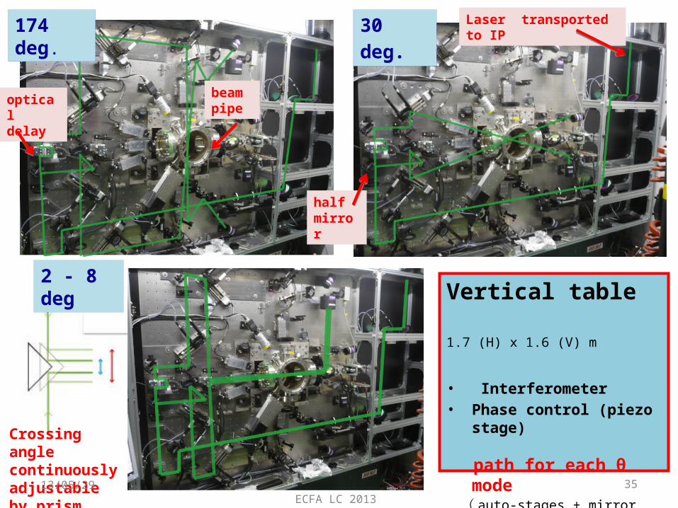
174 deg. 30 deg.
2 - 8 deg
Crossing angle continuously adjustable by prism 13/05/29
ECFA LC 2013 35
Vertical table 1.7 (H) x 1.6 (V) m
• Interferometer• Phase control (piezo stage)
path for each θ mode ( auto-stages + mirror
actuators )
beam pipe
Laser transported to IP
optical delay
half mirror

transverse : laser wire scan
precise position alignment by remote control
ECFA LC 2013
Role of IPBSM in Beam Tuning
13/05/2936
beforehand …. Construct & confirm laser paths, timing alignment
Longitudinal : z scan
After all preparations ……….
continuously measure σy using fringe scans Feed back to multi-knob tuning
laser spot size σt,laser = 15 – 20 μm
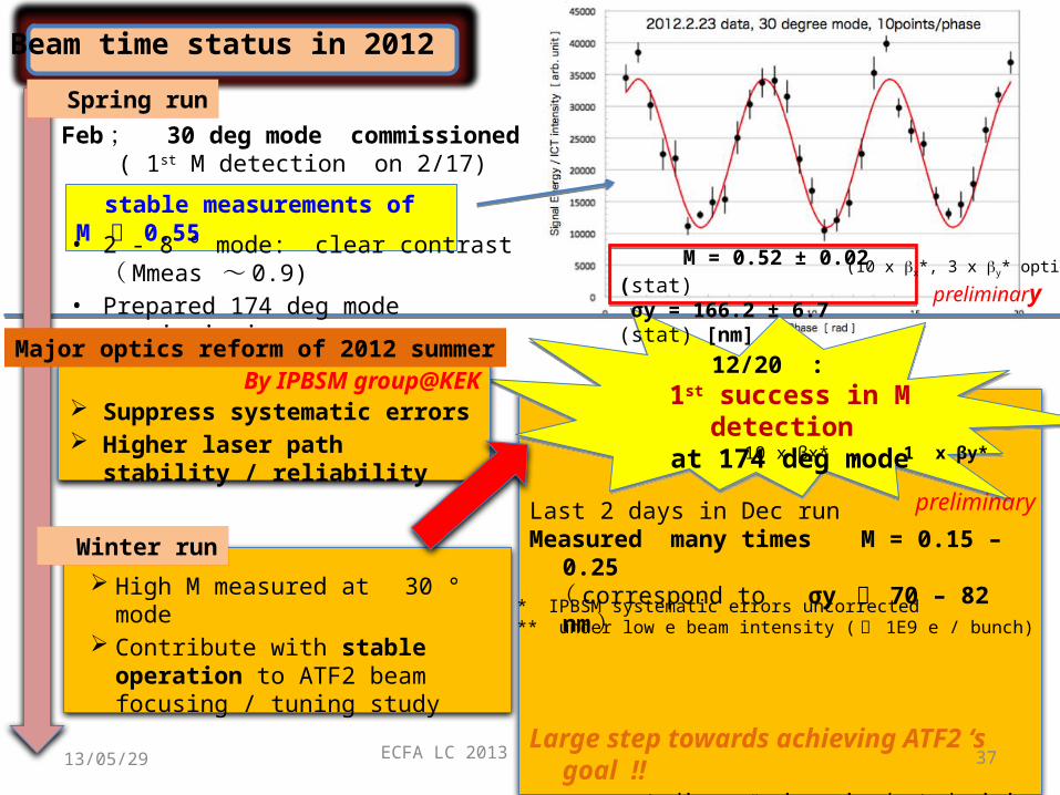
12/20 : 1st success in M detection
at 174 deg mode
Beam time status in 2012
stable measurements of M 〜 0.55
Feb ; 30 deg mode commissioned ( 1st M detection on 2/17)
ECFA LC 2013
M = 0.52 ± 0.02 (stat) σy = 166.2 ± 6.7 (stat) [nm]
• 2 - 8 ° mode: clear contrast ( Mmeas ~ 0.9)• Prepared 174 deg mode commissioning
Suppress systematic errors Higher laser path stability / reliability
High M measured at 30 ° mode Contribute with stable operation to
ATF2 beam focusing / tuning study
(10 x bx*, 3 x by* optics)
Spring run
Major optics reform of 2012 summer
Winter run
Last 2 days in Dec runMeasured many times M = 0.15 – 0.25 ( correspond to σy 〜 70 – 82 nm )
Large step towards achieving ATF2 ‘s goal !! error studies ongoing aimed at deriving “true beamsize”
preliminary
preliminary
* IPBSM systematic errors uncorrected** under low e beam intensity ( 〜 1E9 e / bunch)
10 x βx* , 1 x βy*
By IPBSM group@KEK
13/05/29 37

measured M over continuous reiteration of linear /nonlinear@ tuning knobs @ 174 ° mode
Beam time status in 2013 Spring
ECFA LC 2013
dedicated data for error studies under analysis
ex ) consecutive 10 fringe scans
preliminary
Time passed
measure M vs time after all conditions optimized
preliminary
Stable IPBSM performance major role in beam tuning
10 x bx*, 1 x by*
13/05/29
38
174 ° mode ”consistency scan”
moving towards goal of σy = 37 nm :higher IPBSM precision and stability & looser current limits of normal / skew sextupoles current
M 〜 0.306 ± 0.043 (RMS) correspond to σy 〜 65 nmBest record
from Okugi-san’s Fri operation meeting slides

The Reality… May 2 week Cont. Run
• Summary of all scans during 2 week ops period– Summary plot courtesy of Edu.

40
ILC Project: Mysteries of the Universe
Outreach event in Tokyo, tomorrow, 10.15
41
Report from the Science Council of Japan on ILC
Published September 30
(see comments from LCC
Directorate last week)
Available in Japanese

42
SCJ Report Charge (informal translation)
○ About scientific significance of research at ILC project,
position of ILC within particle physics
○ About the position of ILC project in the whole scientific
community
○ About the impact of carrying out ILC in our country to
nation and society
○ About constraints - such as the required construction
budget, governance of ILC, and securing human resources
43
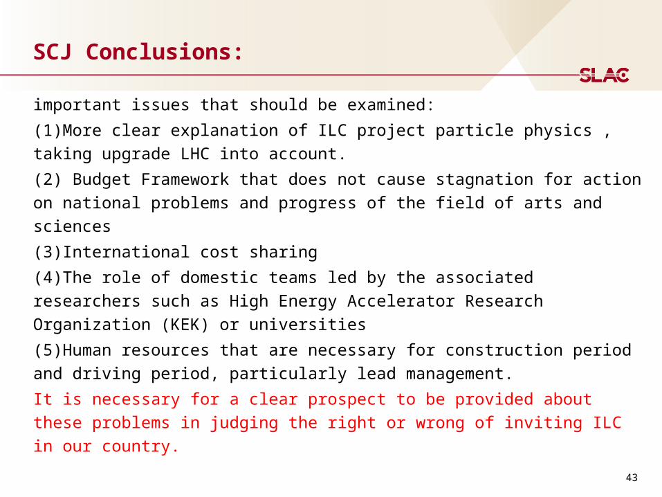
SCJ Conclusions:
important issues that should be examined:
(1)More clear explanation of ILC project particle physics , taking
upgrade LHC into account.
(2) Budget Framework that does not cause stagnation for action on
national problems and progress of the field of arts and sciences
(3)International cost sharing
(4)The role of domestic teams led by the associated researchers such
as High Energy Accelerator Research Organization (KEK) or
universities
(5)Human resources that are necessary for construction period and
driving period, particularly lead management.
It is necessary for a clear prospect to be provided about these
problems in judging the right or wrong of inviting ILC in our country.
44
KEK Internal Evaluation of ILC – including Cost-review
The ILC site selection and SCJ report publication have
helped move the KEK Accelerator Laboratory to launch as
series of meetings for discussion of related issues –
including cost.
(this group is nominally tasked with Super KEK-B
and JParc upgrades.)