Embed Size (px)
Citation preview

IEEE TRANSACTIONS ON ELECTRON DEVICES, VOL. 63, NO. 12, DECEMBER 2016 4939
Analysis of Multipactor RF Breakdown in aWaveguide Containing a Transversely
Magnetized FerriteDaniel González-Iglesias, Álvaro Gómez, Benito Gimeno, Member, IEEE, Óscar Fernández,
Angel Vegas, Member, IEEE, Fernando Casas, Sergio Anza Hormigo, Carlos Vicente, Member, IEEE,Jordi Gil, Rafael Mata, Isabel Montero, Vicente E. Boria, Senior Member, IEEE, and David Raboso
Abstract— In this paper, the multipactor RF breakdown ina parallel-plate waveguide partially filled with a ferrite slabmagnetized normal to the metallic plates is studied. An externalmagnetic field is applied along the vertical direction between theplates in order to magnetize the ferrite. Numerical simulationsusing an in-house 3-D code are carried out to obtain themultipactor RF voltage threshold in this kind of structures. Thepresented results show that the multipactor RF voltage thresholdat certain frequencies becomes considerably lower than for thecorresponding classical metallic parallel-plate waveguide with thesame vacuum gap.
Index Terms— Ferrite devices, magnetic field, multipactoreffect, parallel-plate waveguide, RF breakdown.
I. INTRODUCTION
MULTIPACTOR discharge is an undesired phenomenonthat takes place on devices operating under vacuum
conditions and high-power RF electromagnetic fields [1], [2].
Manuscript received May 13, 2016; revised August 3, 2016; acceptedSeptember 22, 2016. Date of publication October 13, 2016; date of currentversion November 22, 2016. This work was supported in part by the EuropeanSpace Agency under Novel Investigation in Multipactor Effect in Ferrite andother Dielectrics used in high power RF Space Hardware under Contract AO1-7551/13/NL/GLC, in part by the Spanish Government under CoordinatedR&D Project TEC2013- 47037-5-R and Project TEC2014-55463-C3-3-P, andin part by the European Commission (ERDF). The review of this paper wasarranged by Editor R. Carter.
D. González-Iglesias, B. Gimeno, and R. Mata are with the Departamentode Física Aplicada, Universidad de Valencia, 46100 Valencia, Spain (e-mail:[email protected]; [email protected]; [email protected]).
Á. Gómez, Ó. Fernández, and A. Vegas are with the Departamento deIngeniería de Comunicaciones, Universidad de Cantabria, 39005 Santander,Spain (e-mail: [email protected]; [email protected]; [email protected]).
F. Casas is with the Instituto Universitario de Matemáticas y Aplicaciones,Universidad Jaume I, 12071 Castellón de la Plana, Spain (e-mail:[email protected]).
S. Anza Hormigo, C. Vicente, and J. Gil are with AURORASAT,46001 Valencia, Spain (e-mail: [email protected]; [email protected]; [email protected]).
I. Montero is with the Instituto de Ciencia de Materiales de Madrid,Consejo Superior de Investigaciones Científicas, 28049 Madrid, Spain (e-mail:[email protected]).
V. E. Boria is with the Departamento de Comunicaciones, Instituto deTelecomunicaciones y Aplicaciones Multimedia, Universidad Politécnica deValencia, 46022 València, Spain (e-mail: [email protected]).
D. Raboso is with the European Space Research and Technology Centre,European Space Agency, 2201 AZ Noordwijk, The Netherlands (e-mail:[email protected]).
Digital Object Identifier 10.1109/TED.2016.2614370
When certain conditions arise, free electrons in the device aredriven by the RF electric field toward the walls. If the kineticenergy of the impacting electrons is high enough, secondaryelectrons may be released from the surface. As a consequence,a chain reaction leading to an exponential growth of the elec-tron population inside the component is started. The onset ofthe multipactor discharge degrades the device performance byseveral negative effects, such as increasing the signal noise andreflected power, heating up the device walls, outgassing, detun-ing of resonant cavities, vacuum window failure, and evenresulting in the total destruction of the component. Due to that,multipactor phenomenon is revealed as a crucial limitationin the maximum RF power handling. Multipactor occurs indifferent environments, such as passive components of satellitecommunication payloads, particle accelerators, and klystrons.
Special attention must be paid to multipactor in satellitecomponents, where replacement of damaged devices is notpossible. Therefore, in order to ensure that the RF componentwill not suffer this undesirable phenomenon during operation,it is extremely important to take into account this effect inthe design process. In fact, restrictive specifications have beenimposed by the space agencies about this issue [3].
Multipactor has been extensively analyzed in the case ofmetallic surfaces so far [4], [5], [6]. Recently, some studieshave focused their attention to the case wherein dielectricsurfaces are involved [7], [8], [9]. However, very little lit-erature about multipactor effect in devices containing ferritescan be found [10], [11]. Ferrites are ferromagnetic materialswhich exhibit magnetic anisotropy when are brought under adc magnetic bias field. When an external dc magnetic fieldis applied multipactor discharge can be either suppressed [12]or enhanced [13], depending on the specific magnitude anddirection of the external field. The induced anisotropy inthe ferrite has been used to produce a wide range of RFpassive devices, such as circulators, isolators, and phaseshifters [14]–[17]. Until now, the high power handling ofthis kind of components can only be analyzed by roughapproximations whose validity is not clear.
The main aim of this paper is the study of the multipactoreffect in an ideal uniform parallel-plate waveguide (as shownin Fig. 1) of infinite length along the x- and z-axes, z beingthe propagation direction of the electromagnetic wave,
0018-9383 © 2016 IEEE. Personal use is permitted, but republication/redistribution requires IEEE permission.See http://www.ieee.org/publications_standards/publications/rights/index.html for more information.
4940 IEEE TRANSACTIONS ON ELECTRON DEVICES, VOL. 63, NO. 12, DECEMBER 2016
Fig. 1. Parallel-plate waveguide (considered to be infinite along thex- and z-axes, z being the propagation direction of the electromagnetic wave)partially loaded with a ferrite slab magnetized along the waveguide gapdirection by a static magnetic field �H0.
thus resulting an electromagnetic field which does not dependon the x-coordinate. Transmission of the fundamental TEMlike mode is considered in this analysis. The waveguidecontains a lossless ferrite slab, which is magnetized alongthe direction perpendicular to the metallic walls, i.e.,�H0 = H0 y. When the ferrite is saturation magnetized, it
can be electromagnetically characterized by the constitutiverelations �D = ε �E and �B = [μ] �H , wherein ε is the dielectricpermitivitty and [μ] is the Polder’s tensor corresponding tothe aforementioned magnetization [14, eq. 9.27]. The effectivefield Hef which magnetizes the ferrite is Hef = H0 − Ms [14],where Ms is the saturation magnetization. There is agyromagnetic resonance of the ferrite at the Larmor frequencyω0 = γμ0 Hef , where μ0 is the free space permeability, andγ = e/m is the gyromagnetic ratio of the electron (−e and mare the electron charge and electron mass at rest, respectively).
In a previous authors’ work [11], which at first glance couldbe seen similar to the current one, the external magnetizationfield was oriented parallel to the ferrite slab. Since the mag-netic permeability of the ferrite is anisotropic and depends onthe bias magnetic field H0 direction, the RF behavior of theferrite in both cases is completely different. Moreover, theeffect on the electron orbits due to changing the directionof the external magnetic field employed to magnetize theferrite is crucial. Therefore, the present analysis is not only astraightforward extension of the previous one, and it is worthyof being studied.
This paper is structured as follows. First, in Section II,it is described both the multipactor algorithm and the methodemployed to compute the RF electromagnetic fields in suchferrite loaded waveguide. Next, Section III presents and ana-lyzes the results of the multipactor simulations. Finally, themain conclusions of our study are summarized in Section IV.
II. THEORY
A. Multipactor Algorithm
The simulation code developed for the study of the mul-tipactor is based on the single effective electron model [4].This method consists of tracking the individual trajectoriesof a set of effective electrons. Each effective electron hasassociated a cumulative electron population that takes intoaccount the emission or absorption of secondary electronsby the device walls. This is done by computing the valueof the secondary electron yield (SEY) function (δ) at each
impact, which depends on the electron kinetic energy andimpacting angle [18], [19]. After the impact, the collidingeffective electron is launched back to the waveguide withrandom velocity given by a Maxwellian distribution with amean certain kinetic energy (3 eV in our simulations). Thevelocity angle follows the cosine law distribution [20]. Whenthe software has run for a predefined number of RF periods,the code stops and the time evolution of the total electronicpopulation is shown.
The individual trajectories of the effective electrons arecomputed by solving numerically their nonrelativistic equa-tions of motion derived from the Lorentz Force. The totalelectromagnetic field experienced by the electron is the super-position of the RF electric ERF and magnetic BRF fields,the electric field due to the space charge effect Esc, the dcelectric field appearing because of the charging of the ferritesurface Edc, and the external magnetic field H0 employed tomagnetize the ferrite. Both Esc and Edc have been computedfollowing the procedure reported in [7].
For the numerical integration of the differential equationsof the electron trajectories, we use a conveniently modifiedvelocity-Verlet method. This particular scheme has very favor-able properties concerning the error propagation in time, bothin the energy and the position and velocity. We choose the timestep size so that the relative error in position and in energy isless than 1% after a time of 200 RF periods.
B. RF Electromagnetic Field Computation
The RF electromagnetic field inside the structure understudy has been obtained with the aid of the coupledmode method (CMM). This well-known numerical method,formulated in the frequency domain, has been widely andsuccessfully used in the analysis of the electromagnetic wavepropagation inside uniform waveguides that contain anyisotropic, anisotropic, or complex material [21], [22], [23].
In few words, the CMM is a method of moments, whichconsists on expanding the electromagnetic field componentsinside the structure under analysis in terms of a set ofbase functions previously defined [21]. In many cases, thesebase functions correspond to the electric or magnetic fieldcomponents of the TE and TM modes of the empty waveguide.Therefore, they are called basis modes. According to this idea,any component of the electromagnetic field of the structureunder test can be expressed as a linear combination of thebasis modes.
Once the electromagnetic fields inside the waveguide areobtained, the calculation of the equivalent voltage V0 is doneby integrating the vertical RF electric field along the vacuumgap.
III. SIMULATIONS
In order to compute the multipactor RF voltage thresholdfor the parallel-plate ferrite loaded waveguide shown in Fig. 1,numerical simulations have been performed. For all the consid-ered cases, the ferrite thickness h and the vacuum gap d havebeen selected to match with the height of a WR-90 rectangularwaveguide, i.e., b = d + h = 10.16 mm. The saturation
GONZÁLEZ-IGLESIAS et al.: ANALYSIS OF MULTIPACTOR RF BREAKDOWN IN A WAVEGUIDE 4941
Fig. 2. Real and imaginary parts of the propagation factor for the fundamentalmode of a ferrite loaded waveguide (with d = 1 mm) as a function of theRF frequency. Note that gyromagnetic resonance, given by Larmor frequency,occurs at 3.34 GHz.
magnetization of the ferrite is 4π Ms = 1806 G, its relativedielectric permittivity εr = 15, and its SEY parametersare: first crossover energy for SEY coefficient equal to unity,W1 = 19 eV, maximum SEY coefficient δmax = 2.88, andimpact kinetic energy for δmax, Wmax = 289 eV [24]. Forsimplicity, the same SEY parameters are selected for thetop metallic wall. The external magnetic field employed tomagnetize the ferrite is H0 = 3000 Oe. Consequently, theeffective biasing field inside the ferrite is Hef = 1194 Oe. Theconsidered fields are those corresponding to the fundamentalmode of the ferrite loaded waveguide (i.e., l = 1). For allcalculations of the electromagnetic field components with theCMM, a total number of 75 TE and 75 TM basis modes areused. These basis modes have been included by increasingtheir cutoff frequencies.
We are interested in analyzing the effect of the variationof the ferrite thickness and the vacuum gap length in themultipactor RF voltage threshold. First, for the fundamentalmode, the propagation factor dependence with frequency itis obtained, as shown in Fig. 2. It can be observed that thereal part of the propagation factor is zero within the plottedfrequency range, which corresponds to a propagative mode.
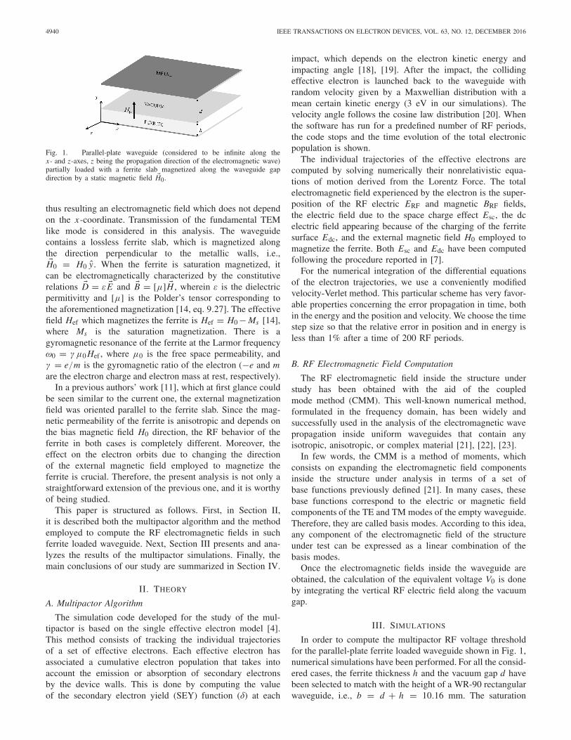
In Fig. 3, the variation of the multipactor RF voltagethreshold as a function of the frequency gap value (i.e., themultipactor susceptibility chart) is shown for several ferriteloaded parallel-plate waveguides. Note that for each curve,the gap remains fixed. Moreover, the results for a classicalmetallic parallel-plate waveguide with no ferrite slab, a gap ofd = 0.2 mm and H0 = 0 (henceforth referred as without ferritecase) has been included for comparison purpose. Rememberthat according to the well-known multipactor theory [2] fora classical metallic parallel-plate waveguide, the multipactorphenomenon depends only on the frequency gap product, andas a consequence, the same multipactor RF voltage thresholdcurve would be obtained for metallic parallel-plate waveguideswith other gaps while maintaining the same frequency gaprange. From the results (recall Fig. 3), it is noticed that thereis considerable difference between the multipactor RF voltage
Fig. 3. Multipactor RF voltage threshold as a function of the frequencygap. Results are presented for parallel-plate ferrite loaded waveguides withdifferent gap lengths and ferrite thicknesses (but maintaining the height of aWR-90 waveguide), and also for a metallic parallel-plate waveguide (“withoutferrite”).
threshold of the ferrite loaded waveguides and the corre-sponding to the without ferrite case. It is found that thisdiscrepancy increases with the gap value. In fact, the maximumdifference in the multipactor RF voltage threshold between thed = 0.2 mm waveguide and the without ferrite case isof 6.5 dB, while in the d = 1 mm and d = 2 mm, thedifference becomes of 26 and 37 dB, respectively. It is alsoobserved that the multipactor behavior of the ferrite loadedwaveguides remains very close to the without ferrite case forlow-frequency gap values (below 2.5 GHzmm). In generalterms, the multipactor RF voltage threshold of the ferriteloaded waveguide cases tends to be equal or below the withoutferrite multipactor threshold.
In order to have a better understanding of the behaviorof the different multipactor susceptibility curves, a detailedanalysis of the RF electromagnetic fields (spatial distribution,scale analysis of the different electric, and magnetic spatialcomponents), and electron dynamics (resonant trajectoriesand multipactor order) has been performed for both theferrite loaded waveguides and the classical unloaded metallicparallel-plate waveguide.
An exhaustive inspection of the RF electromagnetic fieldpattern of the three ferrite loaded waveguide cases has revealedthat the RF magnetic field has very little influence in the elec-tron motion, and thus, the contribution of the terms vi BRF, j
(being i, j = x, y, z) can be neglected in the differentialequations of the electron motion. Regarding the RF electricfield components, it has been found that all of them havenoticeable effects in the electron trajectories. In Fig. 4 (left), ithas been depicted the quotient between the maximum absolutevalue along the gap of the ERF,x and ERF,y componentsfor the different considered ferrite waveguides. In a similarway in Fig. 4 (right), it has been plotted the same quotientfor the ERF,z and ERF,y components. From these figures, itis extracted that the ERF,y is the greater RF electric fieldcomponent for low-frequency gap values. As the frequency
4942 IEEE TRANSACTIONS ON ELECTRON DEVICES, VOL. 63, NO. 12, DECEMBER 2016
Fig. 4. Left (right): quotient between the maximum absolute value alongthe gap of the ERF,x (ERF,z ) and ERF,y components for the ferrite loadedwaveguides.
gap increases the components, ERF,x and ERF,z also growwith regard to the ERF,y component. This increment is foundto be more notorious for the ferrite loaded waveguides withhigher gaps. In fact, it can be observed that ERF,x becomes thedominant component in the d = 2 mm waveguide for valuesabove 15 GHz mm.
Taking the previous statements into account, the differentialequations of motion can be approximated in the following wayfor the earlier stages of the electron multiplication:
dvx
dt� ωcvz − e
mERF,x cos(ωt + φ) (1)
dvy
dt� − e
mERF,y cos(ωt + φ) (2)
dvz
dt� −ωcvx − e
mERF,z sin(ωt + φ) (3)
where ERF,x , ERF,y , and ERF,z are the x , y, and z RFelectric field components, respectively, which only dependon the y-coordinate; ωc = (e/m)μ0 H0 is the cyclotronangular frequency, ω = 2π f is the RF angular frequency( f being the RF frequency), vx , vy , and vz are the x-, y-, andz-components of the velocity vector, respectively, and φ is thephase of the RF electromagnetic field. It is remarkable that insuch conditions, the equation of motion for the y-coordinategets decoupled from the remaining x- and z-coordinates.Indeed, the approximated y-equation of motion becomes thecorresponding one of the analytically well-studied classicalcase without ferrite [1], [2]. The effect of the external field H0is to spin the electron orbits in the xz plane. In addition, theERF,x and ERF,z components accelerate the electron along thedirections x and z, respectively. Manipulating the expressions(1) and (3), the following differential equations arise for thevx and vz velocities:
d2vx
dt2 + ω2c vx = A1 sin(ωt + φ) (4)
d2vz
dt2 + ω2c vz = A2 cos(ωt + φ) (5)
where A1 = (e/m)(ERF,x,0 ω − ERF,z,0 ωc) and A2 = (e/m)(ERF,x,0 ωc − ERF,z,0 ω). The above differential equations canbe solved analytically provided that the amplitude of the RFelectric field components is uniform along the gap. Althoughthis is not true in our case, we will take this assumption inorder to obtain some analytical expressions that can give usa certain qualitative insight of the multipactor phenomenon.After some calculations, the following expressions arise for
Fig. 5. From left to right, and up to down: effective electron velocitycomponents as a function of the time normalized to the RF period (T isthe RF period), and xz plane electron trajectory. All for a ferrite waveguidewith d = 1 mm, f × d = 8.5 GHzmm, V0 = 25 V.
the vx and vz velocities (it is assumed zero initial velocity forboth coordinates):
vx = A1
ω2c − ω2 sin(ω t + φ) − A1 sin(φ)
ω2c − ω2 cos(ωc t)
− A2 cos(φ)
ω2c − ω2 sin(ωc t) (6)
vz = A2
ω2c − ω2 cos(ω t + φ) − A2 cos(φ)
ω2c − ω2 cos(ωc t)
+ A1 sin(φ)
ω2c − ω2 sin(ωc t). (7)
Note that (6) and (7) are valid for all the RF frequencies exceptfor ω = ωc. For both velocities, there are oscillatory termsat both the RF frequency and at the cyclotron frequency. It iseasily noticed that the amplitude of these oscillations becomesmaximum when the RF frequency equals the cyclotron one(ω = ωc). Consequently, the velocity gain in the plane xz ismaximum in the neighborhood of such resonance. In our case,the cyclotron frequency is 8.4 GHz and the correspondingfrequency gap is 8.4 GHz mm for the d = 1 mm waveguideand 16.8 GHz mm for the d = 2 mm waveguide. Thiscyclotron resonance allows to understand the sharp minimumsobserved for the multipactor RF voltage thresholds of theferrite loaded waveguides with d = 1 mm and d = 2 mmin the surroundings of such frequency gap values. Due to theenhance in kinetic energy gain of the electron in the xz plane,less RF voltage amplitude is necessary to achieve that thetotal kinetic impact energy of the electron exceeds the W1of the material. To illustrate the cyclotron resonance effect,in Fig. 5, we have plotted the vx , vy , and vz velocities of aneffective electron in the d = 1 mm ferrite loaded waveguide,for a frequency gap value close to the resonance and an RFvoltage value corresponding to the multipactor threshold. It isnoticed the increment of the vx and vz maximum amplitudein the successive oscillations between one impact and next,while for the vy velocity, it is not observed such maximum
GONZÁLEZ-IGLESIAS et al.: ANALYSIS OF MULTIPACTOR RF BREAKDOWN IN A WAVEGUIDE 4943
amplitude increment. In Fig. 5, it has also been depicted thexz plane electron trajectory, which seems very similar to thatof a cyclotron accelerator, where the radius of the electroncircular trajectory tends to increase as the kinetic energy gainprocess is ongoing.
The above statements justify the presence of a sharp mini-mum in the multipactor RF voltage threshold for the frequencygap values in the vicinity of the cyclotron resonances for thed = 1 mm and d = 2 mm ferrite loaded waveguide cases.However, it is notorious that such multipactor RF voltagethreshold minimum is not observed for the d = 0.2 mmwaveguide (which should be expected at 1.68 GHz mm).To understand this point, we will briefly recall some aspectsof the classic multipactor theory for parallel-plate waveguides.As it is well known, for the onset of a multipactor discharge,it is required that the electron becomes synchronized withthe RF electric field (it implies the apparition of stableresonant trajectories, also known as multipactor modes), andan electron impact kinetic energy with the waveguide wallsabove the W1 parameter of the material (which ensuresthe release of secondary electrons). The classical multi-pactor modes that guarantee the electron synchronizationwith the RF electric field consist on electron trajectoriesthat take an odd number of RF semiperiods to cross thegap (the multipactor order N is defined as that number ofRF semiperiods).
In our ferrite loaded waveguide case, we have argued pre-viously that the y motion becomes decoupled from the x- andz-coordinates, resulting in the same y differential equation ofmotion that for the classical metallic parallel-plate waveguide.The only difference in the y equation of motion betweenthe unloaded ferrite waveguide and the ferrite waveguide isthat, in the latter case, the ERF,y is inhomogeneous alongthe gap. However, we can take the assumption of spatialhomogeneity as a first approach to our problem. When suchconsideration is done, we can use the classical multipactormodes and formulas to qualitatively explain the ferrite loadedwaveguide. We will rely on two expressions to reach this aim.The first expression, V0,min, gives the minimum RF voltagethat guarantees a resonant multipactor of order N . To deducesuch equation we have imposed that an electron starting fromy = 0 arrives to y = d in a time (NT /2, then we havesearched the starting phase of the RF field (φ) that gives thelowest RF value [1], [2]
V0,min = m
e
(ωd)(ωd − v0yπ N)
2√
1 + (π N
2
)2(8)
where v0y is the y-component of the initial velocity. It mustbe remarked that the RF voltage calculated with (8) doesnot ensure that the kinetic energy due to vy is above theW1 parameter. The second expression is for the RF voltagethat ensures a resonant multipactor mode of order N with anelectron impacting with a kinetic energy of W1, i.e., V0,W 1.In some cases, the values given by expressions of V0,W 1or V0,min may not correspond to valid resonant trajectories.The procedure to deduce V0,W 1 consists of imposing the twoaforementioned conditions in the equations of the y trajectory
TABLE I
MULTIPACTOR MODES FOR f × d = 8.4 GHz mm
and the vy velocity. Finally, it is obtained that
V0,W1 = m
e
(ωd)(ωd − v0yπ N)
π N sin φW1 − 2 cos φW1
φW1 = arc cot
(π N
2− ωd − v0yπ N
viy
)(9)
where viy is the y impacting velocity that is set to matchwith the W1 kinetic energy. Note that expressions (8) and (9)depend on the frequency gap product. For each frequency gapvalue, it can be estimated the minimum RF voltage at whicheach of the multipactor modes appears.
The first multipactor modes at a frequency gap valueof 8.4 GHz mm are shown in Table I. The first columnindicates the order of the multipactor mode N ; second columngives the RF voltage to ensure the resonant electron impactswith a kinetic energy equal to the W1 (19 eV in our case) of thematerial, V0,W1; third column provides the minimum RF volt-age at which the resonant trajectories appear, V0,min, and fourthcolumn is for the electron impact kinetic energy when the RFvoltage is V0,min and Wi,V0,min . If Wi,V0,min is equal or aboveW1 then V0,min is the multipactor RF voltage threshold for theN mode, if not the multipactor RF voltage threshold is V0,W 1.At the view of the results summarized in Table I, the N = 9multipactor mode appears at an RF voltage threshold lowerthan the other available modes (N = 1, 3, 5, 7), which appearat higher RF voltages than the multipactor threshold. Electronresonant trajectories with N = 11, 13, 15, . . . may appearbut cannot contribute to the eventual onset of the dischargesince their impacting energies are below W1. The results ofthe multipactor numerical simulations for the without ferritewaveguide are in concordance with the theoretical predictionsof Table I. Indeed, in Fig. 6 (left), it is depicted the effectiveelectron vertical trajectory at 8.4 GHz mm in the multipactorRF voltage threshold, revealing the presence of a resonantmultipactor with N = 9. In Fig. 6 (right), it is depicted theeffective electron vertical trajectories at the same frequencygap in the multipactor RF voltage threshold for the ferriteloaded waveguide with d = 1 mm. Note that at this frequencygap, the cyclotron resonance occurs and the multipactor RFvoltage threshold is clearly below the without ferrite value.For this case, it cannot be found a well-defined multipactororder, instead a hybrid multipactor than ranges from order
4944 IEEE TRANSACTIONS ON ELECTRON DEVICES, VOL. 63, NO. 12, DECEMBER 2016
Fig. 6. Vertical coordinate effective electron trajectories as a function ofthe time normalized to the RF period, f × d = 8.4 GHz mm. Left: metallicparallel-plate waveguide (without ferrite case), V0 = 518 V. Right: ferriteloaded waveguide with d = 1 mm and V0 = 25 V.
TABLE II
MULTIPACTOR MODES FOR f × d = 1.68 GHz mm
15 to 19 appears [see Fig. 6 (right)]. According to Table I, forsuch multipactor modes, there are no RF voltages that give animpact kinetic energy of the electron equal or above the W1 ofthe material. Although resonant trajectories can appear (whenthe RF voltage exceeds V0,min), their impacting energies arequite below the W1 (5.4 and 3.5 eV for the multipactor orders17 and 19, respectively). However, these impacting energieshave been obtained for the classical metallic parallel-platewaveguide (without ferrite), where there is only vertical RFelectric field that accelerates the electron along that spatialdirection. In the ferrite loaded case, the RF electric fields in thetransverse xz plane induce an acceleration, which is uncoupledfrom the vertical dynamics of the electron but contributes toits total kinetic energy. Indeed, after analyzing the differentspatial contributions to the electron total kinetic energy, it isnoticed that the xz plane contribution notoriously exceeds thevertical contribution (recall Fig. 5). This occurs because thexz plane acceleration is maximum at the frequency gap valuethat fits the cyclotron resonance. This fact allows to reduce themultipator RF voltage threshold in the ferrite case with regardto the without ferrite case, thus moving from a multipactororder 9 (without ferrite case) to a 17–19 multipactor order(ferrite case).
In the same way that for Table I, the first resonant modesfor f × d = 1.68 GHz mm are shown in Table II. At thisfrequency gap value, only the multipactor mode with N = 1can contribute to the multipactor discharge in the unloadedferrite waveguide. Resonant trajectories with orders 3 and 5may exist, but their impacting energies are insufficient torelease secondary electrons. In Fig. 7 (left), it is depicted theeffective electron vertical trajectory at 1.68 GHz mm in themultipactor RF voltage threshold for the without ferrite case;it can be observed the presence of the predicted multipactormode of order 1. In Fig. 7 (right), it is also shown the effectiveelectron vertical trajectory at the same frequency gap valuefor the ferrite waveguide with d = 0.2 mm; it is noticedthe presence of the same multipactor mode (N = 1) that
Fig. 7. Vertical coordinate effective electron trajectories as a function of thetime normalized to the RF period, f × d = 1.68 GHz mm. Left: metallicparallel-plate waveguide (without ferrite case), V0 = 104 V. Right: ferriteloaded waveguide with d = 0.2 mm and V0 = 103 V.
in the without ferrite case. Although for the ferrite case thefrequency gap value matches the cyclotron resonance, the otheravailable multipactor modes (N = 3 and N = 5) have tooshort flight time between successive impacts with the devicewalls, preventing the energy gain in the xz plane due to thecyclotron resonance. This fact justifies that the multipactor RFvoltage thresholds are equal in the loaded and unloaded ferritecases.
As it is well stated in the classical multipactor theory,the number of multipactor modes available for a multipactordischarge grows as the frequency gap increases [2]. In thesame way, the flight time between successive electron impactsrises up as the multipactor order does. Thus, low-frequencygap values imply low crossing gap times for the electrons.This fact justifies similarity in the multipactor RF voltagethreshold between the ferrite waveguide and the without ferritecases for the low-frequency gap values (remember Fig. 3).Despite the presence of the accelerating RF electric field in thexz plane, the contribution to the electron kinetic energy is quitelow due to short transit time. However, when the frequencygap increases the flight time also does, allowing higher gainin the transverse plane kinetic energy, and so reducing themultipactor RF voltage threshold regarding the without ferritecase (recall Fig. 3).
Previously, we have analyzed ferrite waveguides with thevacuum gaps of 0.2, 1, and 2 mm, and a total height equal tothe standard WR-90 waveguide. For completeness, we try aferrite loaded waveguide with a gap of d = 5 mm. Accordingto the above statements, for the frequency gap value thatmatches the cyclotron resonance (in this case 42 GHzmm),it is expected a sharp minimum in the multipactor RF voltagethreshold. Indeed, the results from the numerical simulationsfor the multipactor RF voltage threshold in the d = 5 mmferrite waveguide shown in Fig. 8 confirm this statement.It should be remarked that for a classical metallic parallel-plate waveguide, no multipactor discharge is expected at suchhigh-frequency gap values at the RF voltage levels employedin the RF satellite telecommunication systems.
Finally, it has been analyzed the case of having differentSEY coefficients for the ferrite and the metal surface. The SEYparameters for the ferrite remain the same that were describedpreviously in this section, while the SEY coefficients for themetal are those from the ECSS silver [3], i.e., W1 = 30 eV,Wmax = 165 eV, and δmax = 2.22. In Fig. 9, it is shownthe multipactor RF voltage threshold for the ferrite waveguide
GONZÁLEZ-IGLESIAS et al.: ANALYSIS OF MULTIPACTOR RF BREAKDOWN IN A WAVEGUIDE 4945
Fig. 8. Multipactor RF voltage threshold as a function of the frequency gapfor a ferrite waveguide with d = 5 mm and b = 10.16 mm.
Fig. 9. Multipactor RF voltage threshold as a function of the frequency gapfor a ferrite waveguide with d = 0.2 mm and b = 10.16 mm, consideringthe same SEY properties for both surfaces and considering different SEYs forferrite and metal (silver) surfaces.
with d = 0.2 mm considering the ferrite and silver SEYproperties, as well as the results considering the same SEYproperties for both surfaces. It is observed slight differencesbetween both cases. Note that the multipactor RF voltagethreshold in the ferrite and silver SEY case tends to be greaterthan in the case with the same SEY in both surfaces, this isbecause the W1 for silver is above the W1 for the ferrite, andmore RF voltage amplitude is required in the former case toreach the multipactor threshold.
IV. CONCLUSION
In this paper, the multipactor effect in a parallel-platewaveguide containing a magnetized ferrite slab has beenstudied. In order to magnetize the ferrite, an external staticmagnetic field oriented along the vertical direction wasassumed. A home-made 3-D code based on the effectiveelectron model was developed to carry out numerical simu-lations that allowed to compute the multipactor RF voltagethreshold. The multipactor susceptibility charts obtained show
that the multipactor RF voltage threshold changes with regardto the classical metallic parallel-plate situation with neitherferrite slab nor external magnetic field. In fact, a considerablereduction threshold with respect to the classic parallel-platecase has been found at some frequency gap ranges. Moreover,the analysis of the effective electron trajectories has led toa better understanding of the multipacting phenomenon inwaveguides loaded with magnetized ferrites.
REFERENCES
[1] J. Vaughan, “Multipactor,” IEEE Trans. Electron Devices, vol. 35, no. 7,pp. 1172–1180, Jul. 1988.
[2] A. J. Hatch and H. B. Williams, “Multipacting modes of high-frequency gaseous breakdown,” Phys. Rev., vol. 112, no. 3, pp. 681–685,Nov. 1958.
[3] Multipaction Design and Test, document ECSS-E-20-01A, ESA-ESTEC,2003.
[4] A. M. Pérez et al., “Prediction of multipactor breakdown thresholds incoaxial transmission lines for traveling, standing, and mixed waves,”IEEE Trans. Plasma Sci., vol. 37, no. 10, pp. 2031–2040, Oct. 2009.
[5] V. E. Semenov, E. I. Rakova, D. Anderson, M. Lisak, and J. Puech,“Multipactor in rectangular waveguides,” Phys. Plasmas, vol. 14, no. 3,p. 033501, 2007.
[6] V. E. Semenov, N. A. Zharova, D. Anderson, M. Lisak, and J. Puech,“Simulations of multipactor in circular waveguides,” Phys. Plasmas,vol. 17, no. 12, p. 123503, 2010.
[7] A. Coves, G. Torregrosa-Penalva, C. Vicente, B. Gimeno, andV. E. Boria, “Multipactor discharges in parallel-plate dielectric-loadedwaveguides including space-charge effects,” IEEE Trans. ElectronDevices, vol. 55, no. 9, pp. 2505–2511, Sep. 2008.
[8] L. K. Ang, Y. Y. Lau, R. A. Kishek, and M. Gilgenbach, “Powerdeposited on a dielectric by multipactor,” IEEE Trans. Plasma Sci.,vol. 26, no. 3, pp. 290–295, Jun. 1998.
[9] R. A. Kishek, Y. Y. Lau, L. K. Ang, A. Valfells, and R. M. Gilgenbach,“Multipactor discharge on metals and dielectrics: Historical review andrecent theories,” Phys. Plasmas, vol. 5, no. 5, p. 2120, May 1998.
[10] V. E. Semenov et al., “Preliminary results on the multipactor effectprediction in RF components with ferrites,” in Proc. 14th IEEE Int.Vac. Electron. Conf. (IVEC), May 2013, pp. 1–2.
[11] D. González-Iglesias, B. Gimeno, V. E. Boria, A. Gómez, andA. Vegas, “Multipactor effect in a parallel-plate waveguide partiallyfilled with magnetized ferrite,” IEEE Trans. Electron Devices, vol. 61,no. 7, pp. 2552–2557, Jul. 2014.
[12] R. L. Geng, H. Padamsee, S. Belomestnykh, P. Goudket, D. M. Dykes,and R. G. Carter, “Suppression of multipacting in rectangular couplerwaveguides,” Nucl. Instrum. Methods Phys. Res. A, vol. 508, no. 3,pp. 227–238, 2003.
[13] V. E. Semenov et al., “Reduction of the multipactor threshold due toelectron cyclotron resonance,” IEEE Trans. Plasma Sci., vol. 40, no. 11,pp. 3062–3069, Nov. 2012.
[14] M. David Pozar, Microwave Engineering, 4th ed. New York, NY, USA:Wiley, 2012.
[15] A. J. B. Fuller, Ferrites at Microwave Frequencies (IEE ElectromagneticWaves Series). London, U.K.: IET, 2008, p. 280.
[16] J. Helszajn, Waveguide Junction Circulators Theory and Practice.New York, NY, USA: Wiley, 1998.
[17] R. E. Collin, Foundations for Microwave Engineering. 2nd ed.New York, NY, USA: McGraw-Hill, 1992.
[18] S. Anza, C. Vicente, D. Raboso, J. Gil, B. Gimeno, and V. E. Boria,“Enhanced prediction of multipaction breakdown in passive waveguidecomponents including space charge effects,” in IEEE MTT-S Int. Microw.Symp. Dig., Jun. 2008, pp. 1095–1098.
[19] R. M. Vaughan, “Secondary emission formulas,” IEEE Trans. ElectronDevices, vol. 40, no. 4, p. 830, Apr. 1993.
[20] J. Greenwood, “The correct and incorrect generation of a cosine dis-tribution of scattered particles for Monte-Carlo modelling of vacuumsystems,” Vacuum, vol. 67, no. 2, pp. 217–222, Sep. 2002.
[21] S. A. Schelkunoff, “Generalized telegraphist’s equations forwaveguides,” Bell Labs Tech. J., vol. 31, no. 4, pp. 784–801, Jul. 1952.
[22] A. Gómez, J. S. Ipiña M. A. Solano, A. Prieto, and A. Vegas,“Improving the coupled-mode method by means of step functions:Application to partial-height isotropic or anisotropic dielectric parallel-plate waveguides,” Microw. Opt. Techn. Lett., vol. 33, no. 6, pp. 408–414,Jun. 2002.
4946 IEEE TRANSACTIONS ON ELECTRON DEVICES, VOL. 63, NO. 12, DECEMBER 2016
[23] A. Gómez, A. Lakhtakia, A. Vegas, and M. A. Solano, “Hybrid techniquefor analysing metallic waveguides containing isotropic chiral materials,”IET Microw. Antennas Propag., vol. 4, no. 3, pp. 305–315, Mar. 2010.
[24] I. Montero, F. Caspers, L. Aguilera, L. Galán, D. Raboso, andE. Montesinos, “Low-secondary electron yield of ferromagnetic materi-als and magnetized surfaces,” in Proc. IPAC, Kyoto, Japan, May 2010,pp. 23–28.
Daniel González-Iglesias received the Licenci-ado degree in physics and the master’s degree inadvanced physics from the Universidad de Valencia,Valencia, Spain, in 2010 and 2011, respectively,where he is currently pursuing the Ph.D. degree inphysics.
His current research interests include multipactingsimulation of RF high-power passive components.
Álvaro Gómez was born in Santander, Spain, in1976. He received the Licenciado en Ciencias Físi-cas and Ph.D. degrees from the Universidad deCantabria, Santander, Spain, in 2000 and 2005,respectively.
He joined the Departamento de Ingeniería deComunicaciones, Universidad de Cantabria, in 2000,where he became a Profesor Contratado Doctor in2011. His current research interests include elec-tromagnetic propagation in complex materials andnumerical methods in electromagnetics.
Benito Gimeno (M’01) received the Licenciadodegree in physics and the Ph.D. degree from theUniversidad de Valencia, Valencia, Spain, in 1987and 1992, respectively.
He became a Full Professor with the Universidadde Valencia in 2010. His current research interestsinclude the electromagnetic analysis and design ofmicrowave passive components and RF breakdownhigh-power effects.
Óscar Fernández was born in Santander, Spain, in1976. He received the Degree in telecommunicationsengineering and the Ph.D. degree from the Uni-versity of Cantabria, Santander, in 2001 and 2007,respectively. He joined the Department of Commu-nication Engineering, University of Cantabria, in2001. His current research interests include numer-ical methods in electromagnetism and microwavemeasurements.
Angel Vegas (M’98) received the Ph.D. degree inphysical sciences from the University of Cantabria,Santander, Spain, in 1983.
He is currently a Full Professor of Electromag-netics with the University of Cantabria, where heis the Head of the Electromagnetics Group. Hiscurrent research interests include the electromag-netics of complex materials, computer methods inelectromagnetism, and microwave measurements.
Fernando Casas received the Ph.D. degree in the-oretical physics from the University of Valencia,Valencia, Spain, in 1992.
He has been a Professor of Applied Mathematicswith the Universitat Jaume I, Castellon, Spain, since2009. His current research interests include geo-metric numerical integration, including the designand analysis of splitting and composition methodsfor differential equations and their applications, Liegroup methods, perturbation techniques, and thealgebraic issues involved.
Sergio Anza Hormigo received the B.S. degreein telecommunications engineering and the Ph.D.degree from the Universidad Politecnica de Valencia,Valencia, Spain.
He is currently with Aurora Software and TestingSL, Valencia. His current research interests includethe areas of theory and numerical techniques for themodelling and prediction of nonlinear phenomena inRF high power devices for space applications.
Carlos Vicente (M’08) received the Diploma degreein physics from the Universidad de Valencia, Valen-cia, Spain, in 1999, and the Dr.Ing. degree in engi-neering from the Technical University of Darmstadt,Darmstadt, Germany, in 2005.
In 2006, he co-founded Aurora Software and Test-ing SL, Valencia, which is devoted to telecommuni-cations sector. His research concerns the analysis anddesign of passive components for communicationssatellites with a special emphasis on high-powerpractical aspects.
Jordi Gil received the Licenciado degree in physicsfrom the Universidad de Valencia, Valencia, Spain,in 2000, and the Ph.D. degree in telecommunicationsengineering from the Universidad Politécnica deValencia, Valencia, in 2010.
In 2006, he co-founded Aurora Software and Test-ing SL, Valencia, which is devoted to the space sec-tor. His current research interests include numericalmethods in computer-aided techniques for the analy-sis and design of microwave passive components.
GONZÁLEZ-IGLESIAS et al.: ANALYSIS OF MULTIPACTOR RF BREAKDOWN IN A WAVEGUIDE 4947
Rafael Mata received the Degree in physics andthe Ph.D. degree from the Universidad de Valencia,Valencia, Spain, in 2006 and 2011, respectively.
He held a researcher/technician position withthe Val Space Consortium, Valencia, in 2012. Hiscurrent research interests include secondary elec-tron emission properties, outgassing, and ventingprocesses in RF high power space materials.
Isabel Montero is currently a Research Professorwith the Spanish National Research Council (CSIC),Madrid, Spain. She is the Head of the Group Sur-face Nanostructuring for Space and Terrestrial Com-munications, Materials Science Institute of Madrid(ICMM-CSIC), Madrid. She is also the Director ofSpanish Laboratory on secondary electron emission,CSIC.
Vicente E. Boria (S’91–A’99–SM’02) received theDoctor Ingeniero de Telecomunicación degree fromthe Universidad Politécnica de Valencia, Valencia,Spain, in 1997.
He is currently a Full Professor with the Univer-sidad Politécnica de Valencia. His research interestsinclude the electromagnetic analysis and design ofmicrowave passive components and also RF break-down high-power effects.
David Raboso received the Degree in physicsfrom the Autonomous University of Madrid,Madrid, Spainand the master’s degree in spaceengineering from the University of Delft, Delft,The Netherlands.
In 1992, he joined the European Space Agency,The Netherlands, where he became responsible forall activities related to RF breakdown in spacemicrowave components. He has co-authored over100 articles in prestigious journals and a Co-Inventorof nine patents.