Embed Size (px)
Citation preview

IDEC SmartRelay
Manual
March 2001
www.idec.com

Copyright © 2001 IDEC IZUMI CORPORATION All rights reserved
The reproduction, transmission or use of this document or its contents is not permitted
without express written authority. Offenders will be liable for damages. All rights
reserved, in particular in the event of a patent being granted or the registration of a
utility model or design.
Disclaimer of Liability
We have checked the contents of this manual for compliance with the hardware and
software described. Nevertheless, discrepancies may exist. However, the data in this
manual is reviewed regularly and any necessary corrections will be included in
subsequent editions. Suggestions for improvement are welcomed.

iiiIDEC SmartRelay User’s Manual
Contents
1 Getting to Know IDEC SmartRelay 1-1
2 Installing and Wiring IDEC SmartRelay 2-1
2.1 Installing/Removing IDEC SmartRelay 2-2
2.2 Wiring IDEC SmartRelay 2-42.2.1 Connecting the power supply 2-4
2.2.2 Connecting IDEC SmartRelay’s inputs 2-6
2.2.3 Connecting outputs 2-10
2.3 Switching IDEC SmartRelay On/Resumption
of Power Supply 2-12
3 Programming IDEC SmartRelay 3-1
3.1 Connectors 3-2
3.2 Blocks and Block Numbers 3-4
3.3 From the Circuit Diagram toIDEC SmartRelay 3-7
3.4 The 4 Golden Rules for Working with IDECSmartRelay 3-10
3.5 Overview of IDEC SmartRelay’s Menus 3-12
3.6 Entering and Starting a Program 3-133.6.1 Switching to memory cartridge 3-13
3.6.2 First program 3-14
3.6.3 Entering a program 3-16
3.6.4 Second program 3-23
Contents
ivIDEC SmartRelay User’s Manual
3.6.5 Deleting a block 3-30
3.6.6 Deleting a number of interconnected blocks 3-31
3.6.7 Correcting typing errors 3-32
3.6.8 “?“ on the display 3-32
3.6.9 Deleting a program 3-33
3.7 Storage Space and Size of a Circuit 3-34
4 IDEC SmartRelay Functions 4-1
4.1 Constants and Connectors – Co 4-2
4.2 List of General Functions – GF 4-4
4.2.1 AND 4-6
4.2.2 AND with RLO edge detection 4-6
4.2.3 NAND (AND Not) 4-7
4.2.4 NAND with RLO edge detection 4-8
4.2.5 OR 4-8
4.2.6 NOR (OR Not) 4-9
4.2.7 XOR (exclusive OR) 4-10
4.2.8 NOT (negation, inverter) 4-10
4.3 Fundamentals of Special Functions 4-11
4.3.1 Description of the inputs 4-11
4.3.2 Time response 4-12
4.3.3 Clock buffering 4-13
4.3.4 Retentivity 4-13
4.3.5 Degree of protection 4-14
4.3.6 Gain and offset calculation for analog values 4-14
Contents
vIDEC SmartRelay User’s Manual
4.4 List of Special Functions – SF 4-154.4.1 On delay 4-18
4.4.2 Off delay 4-20
4.4.3 On/Off delay 4-22
4.4.4 Retentive on delay 4-24
4.4.5 Latching relay 4-26
4.4.6 Current impulse relay 4-28
4.4.7 Interval time-delay relay – pulse output 4-29
4.4.8 Edge-triggered interval time-delay relay 4-30
4.4.9 Seven-day time switch 4-31
4.4.10 Twelve-month time switch 4-36
4.4.11 Up/Down counter 4-38
4.4.12 Operating hours counter 4-41
4.4.13 Symmetrical clock pulse generator 4-44
4.4.14 Asynchronous pulse generator 4-45
4.4.15 Random generator 4-46
4.4.16 Frequency trigger 4-48
4.4.17 Analog trigger 4-50
4.4.18 Analog comparator 4-53
4.4.19 Stairwell light switch 4-57
4.4.20 Dual-function switch 4-59
4.4.21 Message texts 4-61
5 Parameterizing IDEC SmartRelay 5-1
5.1 Switching to Parameterization Mode 5-2
5.1.1 Parameters 5-2
Contents
viIDEC SmartRelay User’s Manual
5.1.2 Selecting a parameter 5-3
5.1.3 Changing a parameter 5-4
5.2 Setting the Time (FL1A-…C…) 5-7
6 IDEC SmartRelay Memory Cartridge 6-1
6.1 Overview of the Memory Cartridge 6-2
6.2 Removing and Inserting Memory
Cartridge 6-2
6.3 Copying a Program from IDEC SmartRelay to
the Memory Cartridge 6-5
6.4 Copying from the Memory Cartridge to
IDEC SmartRelay 6-6
7 IDEC SmartRelay Software 7-1
7.1 Possible Applications for IDEC SmartRelay
Software 7-2
7.2 Connecting IDEC SmartRelay to PC 7-3
7.3 Transfer Settings 7-4
8 Applications 8-1
8.1 Stairwell or Hall Lighting 8-28.1.1 Demands on stairwell lighting 8-2
8.1.2 Previous solution 8-2
8.1.3 Lighting system with IDEC SmartRelay 8-3
Contents
viiIDEC SmartRelay User’s Manual
8.1.4 Special features and enhancement options 8-6
8.2 Automatic Door 8-7
8.2.1 Demands on an automatic door 8-7
8.2.2 Previous solution 8-8
8.2.3 Door control system with IDEC SmartRelay 8-8
8.2.4 Special features and enhancement options 8-11
8.2.5 Enhanced FL1A-H10RCB solution 8-11
8.3 Ventilation System 8-148.3.1 Demands on a ventilation system 8-14
8.3.2 Advantages of using IDEC SmartRelay 8-16
8.4 Industrial Gate 8-188.4.1 Demands on the gate control system 8-18
8.4.2 Previous solution 8-19
8.4.3 Enhanced IDEC SmartRelay solution 8-21
8.5 Fluorescent Lights 8-22
8.5.1 Demands on the lighting system 8-22
8.5.2 Previous solution 8-23
8.5.3. Fluorescent light control with FL1A-H10RCB 8-24
8.6 Water Pump 8-26
8.6.1 Demands on the control system of a rainwater
Pump 8-27
8.6.2 Previous solution 8-27
8.6.3 Rainwater pump with FL1A-H10RCB 8-28
8.6.4 Special features and enhancement options 8-29
8.7 Further Potential Applications 8-30

Contents
viiiIDEC SmartRelay User’s Manual
A Technical Specifications A-1
A.1 General Technical Specifications A-1
A.2 Technical Specifications: A-3
FL1A-H10RCB, FL1A-B10RCB
A.3 Technical Specifications: A-6
FL1A-H12RCE, FL1A-H10RCA,
FL1A- B10RCA
A.4 Technical Specifications: A-9
FL1A-H12RCE, FL1A-B12RCE
B Determining Memory Requirements B-1
C Determining the Cycle Time C-1
D IDEC SmartRelay Without a Display D-1
E IDEC SmartRelay Menu Structure E-1
F Order Numbers F-1
G Abbreviation G-1

iIDEC SmartRelay User’s Manual
Welcome to IDEC SmartRelayDear customers,Thank you for purchasing IDEC SmartRelay, and congratulationson your decision. In IDEC SmartRelay you have acquired a logicmodule that meets the stringent quality requirements of ISO9001.IDEC SmartRelay is universal in application. Its comprehensivefunctionality and great ease of use make it a highly cost-efficientsolution for virtually any application.
IDEC SmartRelay documentationThis IDEC SmartRelay manual tells you how to install, programand use IDEC SmartRelay.You can find information on wiring in the IDEC SmartRelaymanual as well as in the IDEC SmartRelay product informationthat is supplied with each device. You can get further informationon programming IDEC SmartRelay via the PC in the WindLGConline help system. WindLGC is the IDEC SmartRelayprogramming software for PCs. It runs under WINDOWS and willhelp you get to know IDEC SmartRelay and to write, test, print outand archive programs independently of IDEC SmartRelay.
Guide to the manualWe have subdivided this manual into 9 chapters:• Getting to Know IDEC SmartRelay• Installing and Wiring IDEC SmartRelay• Programming IDEC SmartRelay• IDEC SmartRelay Functions• Parameterizing IDEC SmartRelay• IDEC SmartRelay’s Memory Cartridge• IDEC SmartRelay Software• Applications• Appendices

Welcome to IDEC SmartRelay
iiIDEC SmartRelay User’s Manual
Safety guidelinesThis manual contains notices which you should observe to ensureyour own personal safety, as well as to protect the product andconnected equipment. These notices are highlighted in themanual by a warning triangle and are marked as followsaccording to the level of danger:
!Danger
Indicates that death, severe personal injury or substantial damage to
property will result if proper precautions are not taken.
!Warning
Indicates that death, severe personal injury or substantial damage to
property can result if proper precautions are not taken.
!Caution
Indicates that personal injury or damage to property can result if
proper precautions are not taken.
NoteDraws your intention to particularly important information on the
product, handling the product, or to a particular part of the
documentation.
!Warning
Only qualified personnel should be allowed to install and work on
this equipment. Qualified personnel are defined as persons who are
authorized to commission, to ground and to tag circuits, equipment
and systems in accordance with established safety practices and
standards.
!Warning
This device may only be used for the applications described in the
catalog and the technical description, and only with non-IDEC
devices or components if they have been approved or
recommended by IDEC.
This product can only function correctly and safely if it is transported,
stored, set up, and installed correctly, and operated and maintained
as recommended.
1-1IDEC SmartRelay User’s Manual
1 Getting to Know IDECSmartRelay
What is IDEC SmartRelay ?IDEC SmartRelay is the universal logic module from IDEC.IDEC SmartRelay integrates:• Control functions• An operating and display unit• Power supply• An interface for Memory Cartridges and a PC Cable• Ready–to–use general functions that are often required
in day–to–day operation, such as functions for on/offdelays and current impulse relays
• Time switch• Binary markers• Inputs and outputs according to the device type
What can IDEC SmartRelay do?You can use IDEC SmartRelay for domestic andinstallation engineering tasks (e.g. stairway lighting,external lighting, sun blinds, shutters, shop window lightingetc.), switch cabinet engineering and mechanical andapparatus engineering (e.g. gate control systems,ventilation systems, or rainwater pumps etc.).
Getting to Know IDEC SmartRelay
1-2IDEC SmartRelay User’s Manual
What device types are available?There are IDEC SmartRelay models for 12V DC, 24V DC,24V AC and 100-240V AC as:• FL1A-H10RCA, FL1A-H10RCB, FL1A-B10RCA and
FL1A-B10RCB with 6 inputs and 4 outputs withdimensions of 72 x 90 x 55 mm
• FL1A-B10…, FL1A-B12… without a display withdimensions of 72 x 90 x 55 mm
• FL1A-H12SND, FL1A-H12RCE and FL1A-B12RCE with8 inputs (6 Digital inputs and 2 Analog inputs) and 4outputs with dimensions of 72 x 90 x 55 mm
• IDEC SmartRelay includes 29 ready to use general andspecial functions for program creation.
It’s your choiceThe variety of options can be adapted very easily to yourown specific task.
Getting to Know IDEC SmartRelay
1-3IDEC SmartRelay User’s Manual
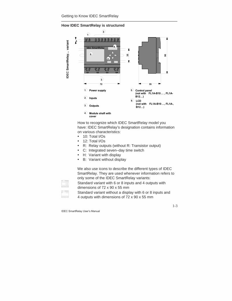
How IDEC SmartRelay is structured
55
Sm
artR
elay
... v
aria
nt
12
3
I7 I8
Q1 Q2 Q3 Q4
L1 N I4 I5 I6I1 I2 I3
idec
3
72
4
6
5
1
2
4
3 Outputs
Power supply
Inputs
Module shaft withcover
5
6
Control panel(not with FL1A-B10… , FL1A-B12…)
LCD(not with FL1A-B10…, FL1A-,B12…)
SmartRelay
35 90
How to recognize which IDEC SmartRelay model youhave: IDEC SmartRelay’s designation contains informationon various characteristics:• 10: Total I/Os• 12: Total I/Os• R: Relay outputs (without R: Transistor output)• C: Integrated seven–day time switch• H: Variant with display• B: Variant without display
We also use icons to describe the different types of IDECSmartRelay. They are used whenever information refers toonly some of the IDEC SmartRelay variants:Standard variant with 6 or 8 inputs and 4 outputs withdimensions of 72 x 90 x 55 mmStandard variant without a display with 6 or 8 inputs and4 outputs with dimensions of 72 x 90 x 55 mm
IDE
C S
mar
tRel
ay…
var
ian
t
idec SmartRelay
Getting to Know IDEC SmartRelay
1-4IDEC SmartRelay User’s Manual
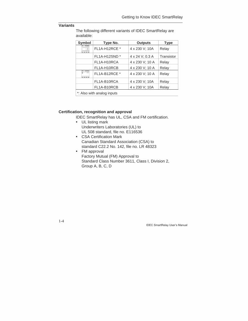
VariantsThe following different variants of IDEC SmartRelay areavailable:
Symbol Type No. Outputs Type
FL1A-H12RCE * 4 x 230 V; 10A Relay
FL1A-H12SND * 4 x 24 V; 0.3 A Transistor
FL1A-H10RCA 4 x 230 V; 10 A Relay
FL1A-H10RCB 4 x 230 V; 10 A Relay
FL1A-B12RCE * 4 x 230 V; 10 A Relay
FL1A-B10RCA 4 x 230 V; 10A Relay
FL1A-B10RCB 4 x 230 V; 10A Relay
*: Also with analog inputs
Certification, recognition and approvalIDEC SmartRelay has UL, CSA and FM certification.• UL listing mark
Underwriters Laboratories (UL) toUL 508 standard, file no. E116536
• CSA Certification MarkCanadian Standard Association (CSA) tostandard C22.2 No. 142, file no. LR 48323
• FM approvalFactory Mutual (FM) Approval toStandard Class Number 3611, Class I, Division 2,Group A, B, C, D

Getting to Know IDEC SmartRelay
1-5IDEC SmartRelay User’s Manual
!Warning
Personal injury and material damage may be
incurred.
In potentially explosive areas, personal injury or
property damage can result if you withdraw a
connector while the system is in operation.
Always ensure that the system is off
before you disconnect IDEC SmartRelay plug
connections and associated components in
potentially explosive areas.
IDEC SmartRelay carries CE marking, complies with theVDE 0631 and IEC 1131 standards and has interferencesuppression to EN 55011 (limit class B).Shipbuilding certification has been granted.• ABS - American Bureau of Shipping• BV - Bureau Veritas• DNV - Det Norske Veritas• GL - Germanischer Lloyd• LRS - Lloyds Register of Shipping• PRS - Polski Rejestr StatkówIDEC SmartRelay can therefore be used both in industryand at home.
Marking for Australia
The marking shown on the left meets the requirements of
the AS/NZS 2064 Standard (Class A).

Getting to Know IDEC SmartRelay
1-6IDEC SmartRelay User’s Manual
2-1IDEC SmartRelay User’s Manual
2 Installing and Wiring IDECSmartRelay
General guidelinesYou should keep to the following guidelines when youinstall and wire your IDEC SmartRelay:• Ensure that you comply with all the valid and mandatory
standards when wiring your IDEC SmartRelay device.You should also heed any national and regionalregulations when installing and operating the devices.Contact the relevant authorities to find out the standardsand regulations that apply in your specific case.
• Use wires with the appropriate cross–section for theamount of current involved. You can wire IDECSmartRelay using wires with a cross–section ofbetween 1.5 mm2 and 2.5 mm2 (see Section 2.2).
• Don’t screw the connectors too tightly. The maximumtorque is 0.5 Nm (see Section 2.2).
• Keep wiring distances as short as possible. If longerwires are necessary, a shielded cable should be used.You should lay wires in pairs: a neutral conductortogether with a phase conductor or signal conductor.
• Isolate AC wiring and high–voltage DC wiring with rapidoperating sequences from low–voltage signal wiring.
• Ensure that the wires have the required strain relief.• Provide suitable over voltage protection for wires that
could be vulnerable to lightning.• Do not connect an external power supply to an output
load parallel to a DC output. This can result in reversecurrent at the output unless you have a diode or asimilar block in your configuration.
NoteIDEC SmartRelay must be installed and wired by a trained technician
who knows and complies with both the universally applicable engineering
rules and the regulations and standards that apply in specific cases.
Installing and Wiring IDEC SmartRelay
2-2IDEC SmartRelay User’s Manual
2.1 Installing/Removing IDEC SmartRelay
DimensionsThe dimensions of IDEC SmartRelay comply withDIN 43880.IDEC SmartRelay must be snapped onto a DIN rail with awidth of 35 mm to DIN EN 50022.Width of IDEC SmartRelay:• IDEC SmartRelay is 72 mm wide, which corresponds to
the size of all modules.
NoteWe will show you how to install and uninstall IDEC SmartRelay
with the aid of an illustration of the FL1A-H10RCB. The
measures described also apply to all other IDEC SmartRelay
modules.
InstallingTo install IDEC SmartRelay on a DIN rail, proceed asfollows:1. Place IDEC SmartRelay on the rail2. Swivel it onto the rail so that the snap catch on the back
of IDEC SmartRelay engages.Depending on the type of DIN rail used, the snappingmechanism may be a bit stiff. If it is too stiff and IDECSmartRelay won’t snap on, you can pull the snap catchdown a little as you do when uninstalling IDEC SmartRelay(as described below).
Installing and Wiring IDEC SmartRelay
2-3IDEC SmartRelay User’s Manual
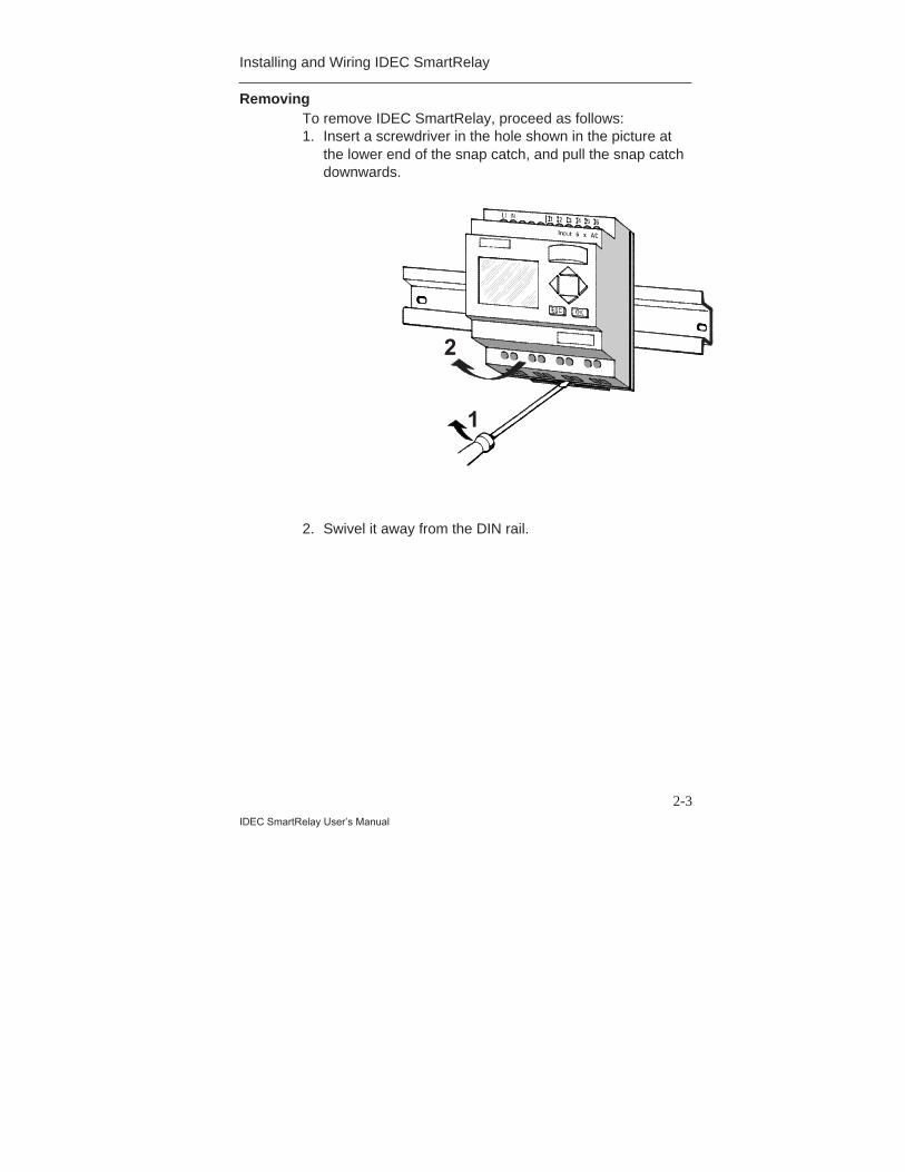
RemovingTo remove IDEC SmartRelay, proceed as follows:1. Insert a screwdriver in the hole shown in the picture at
the lower end of the snap catch, and pull the snap catchdownwards.
1
2
2. Swivel it away from the DIN rail.
Installing and Wiring IDEC SmartRelay
2-4IDEC SmartRelay User’s Manual
2.2 Wiring IDEC SmartRelay
Use a screwdriver with a 3 mm head to wire IDECSmartRelay.You don’t need wire end ferrules for the connectors. Youcan use wires up to the following sizes:• 1 x 2.5 mm2
• 2 x 1.5 mm2 for each second connector compartmentConnecting torque: 0.4...0.5 Nm or 3...4 LBin
NoteInstall IDEC SmartRelay in a distribution box or control
cabinet, ensuring that the connectors are covered. If they are
not, there is a danger of touching live parts.
2.2.1 Connecting the Power Supply
FL1A-H10RCB and FL1A-B10RCB are suitable for linevoltages with a rating of 100V AC and 240V AC. OtherTypes are suitable for 12V DC, 24V DC or 24V AC supplyvoltage. Note the information on connection in the productinformation document shipped with your device and thetechnical specifications in Appendix A relating to thepermissible voltage tolerances, line frequencies andcurrent inputs.
Note
Power failure might result in a voltage spike after power
restoration, which may affect certain edge-triggered function
blocks.
Installing and Wiring IDEC SmartRelay
2-5IDEC SmartRelay User’s Manual
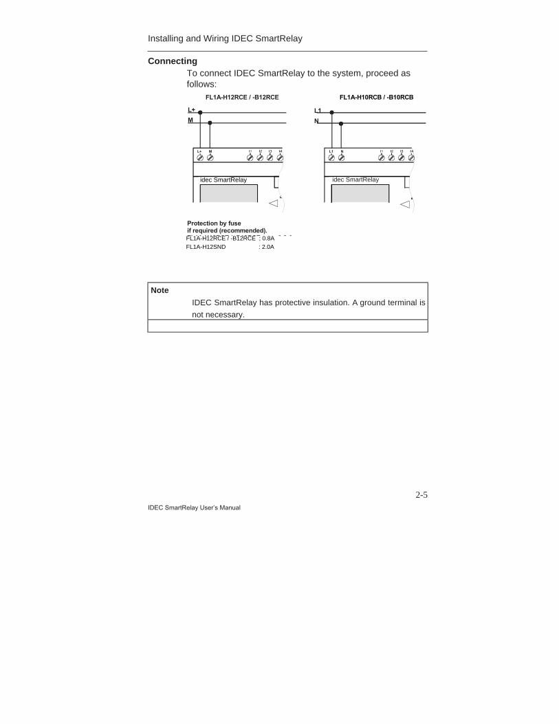
ConnectingTo connect IDEC SmartRelay to the system, proceed asfollows:
L1L+
NM
FL1A-H12RCE / -B12RCE FL1A-H10RCB / -B10RCB
Protection by fuseif required (recommended).FL1A-H12RCE / -B12RCE : 0.8 AFL1A-H12STD : 2.0 A
L+ M
idec idec
L1 N
Note
IDEC SmartRelay has protective insulation. A ground terminal is
not necessary.
idec SmartRelay idec SmartRelay
FL1A-H12RCE / -B12RCE ; 0.8AFL1A-H12SND : 2.0A
Installing and Wiring IDEC SmartRelay
2-6IDEC SmartRelay User’s Manual
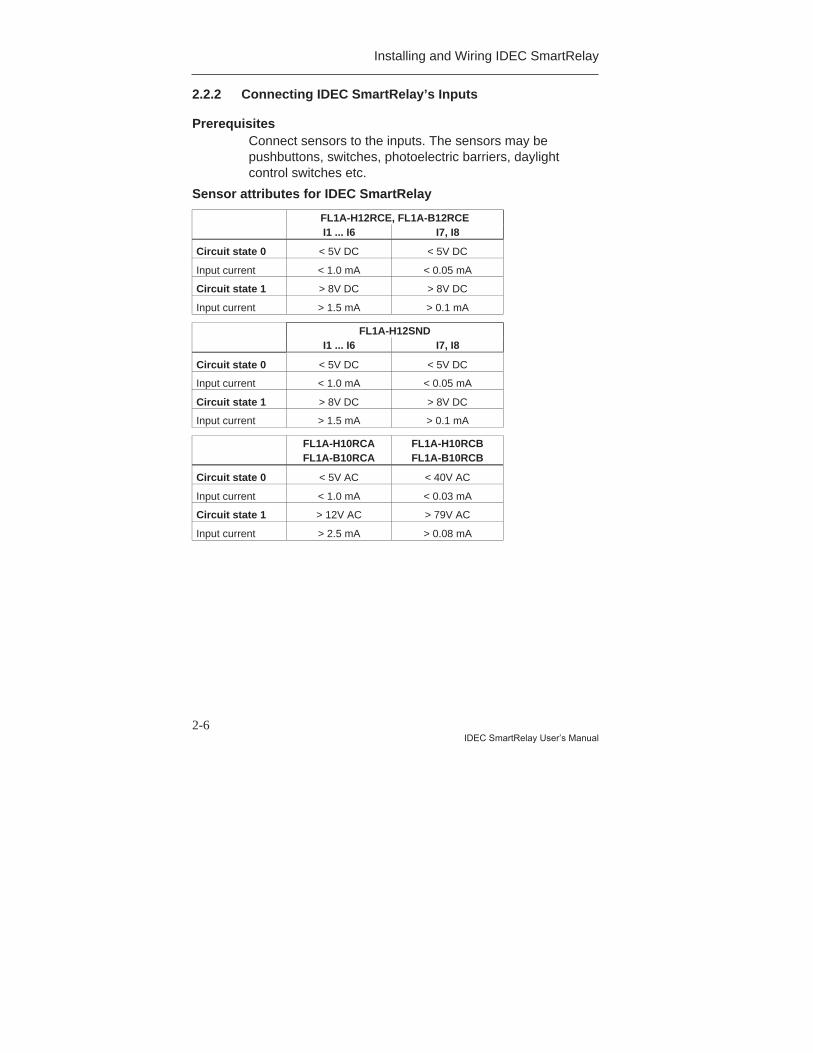
2.2.2 Connecting IDEC SmartRelay’s Inputs
PrerequisitesConnect sensors to the inputs. The sensors may bepushbuttons, switches, photoelectric barriers, daylightcontrol switches etc.
Sensor attributes for IDEC SmartRelay
FL1A-H12RCE, FL1A-B12RCEI1 ... I6 I7, I8
Circuit state 0 < 5V DC < 5V DC
Input current < 1.0 mA < 0.05 mA
Circuit state 1 > 8V DC > 8V DC
Input current > 1.5 mA > 0.1 mA
FL1A-H12SNDI1 ... I6 I7, I8
Circuit state 0 < 5V DC < 5V DC
Input current < 1.0 mA < 0.05 mA
Circuit state 1 > 8V DC > 8V DC
Input current > 1.5 mA > 0.1 mA
FL1A-H10RCAFL1A-B10RCA
FL1A-H10RCBFL1A-B10RCB
Circuit state 0 < 5V AC < 40V AC
Input current < 1.0 mA < 0.03 mA
Circuit state 1 > 12V AC > 79V AC
Input current > 2.5 mA > 0.08 mA
Installing and Wiring IDEC SmartRelay
2-7IDEC SmartRelay User’s Manual
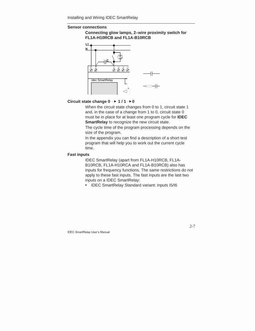
Sensor connectionsConnecting glow lamps, 2–wire proximity switch forFL1A-H10RCB and FL1A-B10RCBL1
N
NL1
C
idec
Circuit state change 0 1 / 1 0When the circuit state changes from 0 to 1, circuit state 1and, in the case of a change from 1 to 0, circuit state 0must be in place for at least one program cycle for IDECSmartRelay to recognize the new circuit state.The cycle time of the program processing depends on thesize of the program.In the appendix you can find a description of a short testprogram that will help you to work out the current cycletime.
Fast inputsIDEC SmartRelay (apart from FL1A-H10RCB, FL1A-B10RCB, FL1A-H10RCA and FL1A-B10RCB) also hasinputs for frequency functions. The same restrictions do notapply to these fast inputs. The fast inputs are the last twoinputs on a IDEC SmartRelay:• IDEC SmartRelay Standard variant: inputs I5/I6
idec SmartRelay
Installing and Wiring IDEC SmartRelay
2-8IDEC SmartRelay User’s Manual
Analog inputsWith units FL1A-H12SND, FL1A-H12RCE and FL1A-B12RCE, the inputs I7 and I8 can be used as normal digitalinputs or as analog inputs. How the input is used dependson its purpose in the IDEC SmartRelay control program.You can use the digital capability of the input with I7/I8 andits analog capability with the identifiers AI1 and AI2.Also see Section 4.1.
NoteAlways use twisted wires for analog signals, and keepthem as short as possible
Installing and Wiring IDEC SmartRelay
2-9IDEC SmartRelay User’s Manual
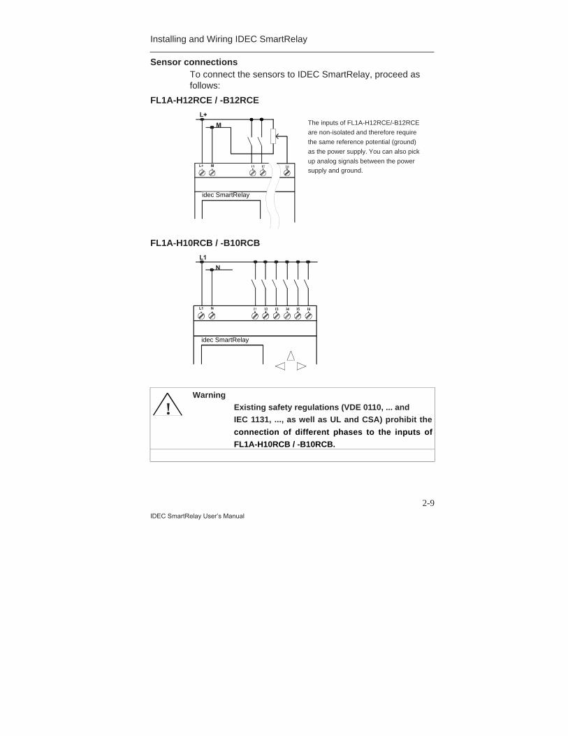
Sensor connectionsTo connect the sensors to IDEC SmartRelay, proceed asfollows:
FL1A-H12RCE / -B12RCEL+
M The inputs of FL1A-H12RCE / -B12RCE are non-isolated and therefore require
the same reference potential (ground) as the power supply.
You can also pick up analog signals between the power supply and
ground.L+ M
idec
FL1A-H10RCB / -B10RCBL1
N
L1 N
idec
!Warning
Existing safety regulations (VDE 0110, ... andIEC 1131, ..., as well as UL and CSA) prohibit the
connection of different phases to the inputs ofFL1A-H10RCB / -B10RCB.
The inputs of FL1A-H12RCE/-B12RCE
are non-isolated and therefore require
the same reference potential (ground)
as the power supply. You can also pick
up analog signals between the power
supply and ground.
idec SmartRelay
idec SmartRelay
Installing and Wiring IDEC SmartRelay
2-10IDEC SmartRelay User’s Manual
2.2.3 Connecting Outputs
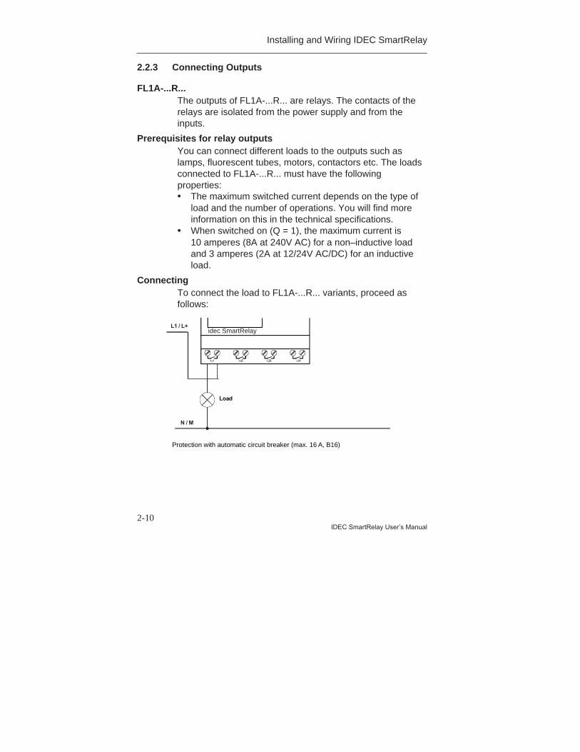
FL1A-...R...The outputs of FL1A-...R... are relays. The contacts of therelays are isolated from the power supply and from theinputs.
Prerequisites for relay outputsYou can connect different loads to the outputs such aslamps, fluorescent tubes, motors, contactors etc. The loadsconnected to FL1A-...R... must have the followingproperties:• The maximum switched current depends on the type of
load and the number of operations. You will find moreinformation on this in the technical specifications.
• When switched on (Q = 1), the maximum current is10 amperes (8A at 240V AC) for a non–inductive loadand 3 amperes (2A at 12/24V AC/DC) for an inductiveload.
ConnectingTo connect the load to FL1A-...R... variants, proceed asfollows:
Protection with automatic circuit breaker (max. 16 A, B16, e.g. power circuitbreaker 5SX2 116-6 (if desired)
Load
L1 / L+
N / M
SmartRelay
idec SmartRelay
Protection with automatic circuit breaker (max. 16 A, B16)

Installing and Wiring IDEC SmartRelay
2-11IDEC SmartRelay User’s Manual
IDEC SmartRelay with transistor outputsIDEC SmartRelay variants with transistor outputs can beidentified by the fact that the letter R is missing from theirtype designation. The outputs are short circuit–proof andoverload–proof. A separate voltage supply to the load isnot necessary since IDEC SmartRelay supplies the loadwith voltage.
Prerequisites for transistor outputsThe load connected to IDEC SmartRelay must have thefollowing properties:• The maximum switched current is 0.3 amperes per
output.
ConnectingTo connect the load to IDEC SmartRelay with transistoroutputs, proceed as follows:
Load: 24 V DC, 0.3 A max.
SmartRelay
Load
idec SmartRelay
Installing and Wiring IDEC SmartRelay
2-12IDEC SmartRelay User’s Manual
2.3 Switching IDEC SmartRelay On/Resumption of Power
Supply
IDEC SmartRelay does not have a power switch. HowIDEC SmartRelay responds when switched on, depends onthe following:• Whether a program is stored in IDEC SmartRelay.• Whether a program module is connected.• Whether it is a IDEC SmartRelay variant without a
display (FL1A-B...).• The state IDEC SmartRelay was in before power off.The table indicates IDEC SmartRelay’s response to thepossible situations:

Installing and Wiring IDEC SmartRelay
2-13IDEC SmartRelay User’s Manual
>Program.. PC/Card.. Start
>Program.. PC/Card.. Start
>Program.. PC/Card.. Start
No Program No Program
I:123456
Q:1234 RUN
Mo 09:00
With stored pro - gram from SmartRelay
& B01 Q1
No program in memory
(empty)
(with program)
or
B03:Pa
Cnt = 0028
Par = 0300
SmartRelay in RUN
(empty)
(with program)
or
I:123456
Q:1234 RUN Mo 09:00
I:123456
Q:1234 RUN Mo 09:00
Program in memory (empty)
or
With program copied from memory cartridge to SmartRelay
Before power off After power on
((with program)
With stored pro - gram from SmartRelay
With program copied from Memory cartridge to SmartRelay
Try to remember the 4 simple rules for starting IDECSmartRelay:1. If there is no program in IDEC SmartRelay or on the
connected memory cartridge, IDEC SmartRelay (withdisplay) displays the message: No Program.
2. If there is a program on the program module, it isautomatically copied to IDEC SmartRelay. If there isalready a program in IDEC SmartRelay, it is overwritten.
IDEC SmartRelay in RUN
With stored programfrom IDECSmartRelay.
With program copiedfrom memorycartridge to IDECSmartRelay.
With stored programfrom IDECSmartRelay.
With program copiedfrom memorycartridge to IDECSmartRelay.
Installing and Wiring IDEC SmartRelay
2-14IDEC SmartRelay User’s Manual
3. If there is a program in IDEC SmartRelay or on thememory cartridge, IDEC SmartRelay adopts theoperating status it had before power off. If you are usinga variant without display (FL1A-B…), it automaticallychanges from STOP to RUN (the LED changes from redto green).
4. If you have switched on retentivity for at least onefunction or are using a function with retentivitypermanently switched on, its current values are retainedat power off.
NoteIf a power failure occurs while you are entering a program, you
will find when the power is restored that IDEC SmartRelay no
longer contains the program.
You should therefore save your original program before changing
it on a Memory Cartridge or on a computer (WindLGC).
Installing and Wiring IDEC SmartRelay
2-15IDEC SmartRelay User’s Manual
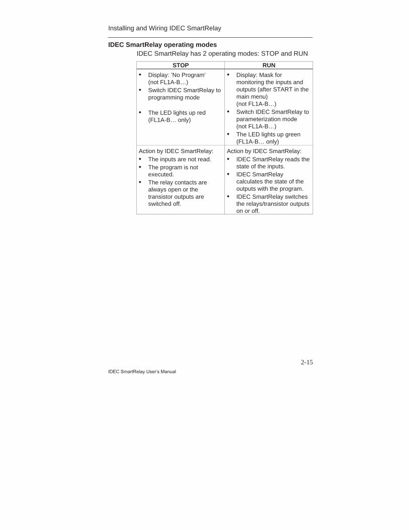
IDEC SmartRelay operating modesIDEC SmartRelay has 2 operating modes: STOP and RUN
STOP RUN
• Display: ’No Program’(not FL1A-B…)
• Switch IDEC SmartRelay toprogramming mode
• The LED lights up red(FL1A-B… only)
• Display: Mask formonitoring the inputs andoutputs (after START in themain menu)(not FL1A-B…)
• Switch IDEC SmartRelay toparameterization mode(not FL1A-B…)
• The LED lights up green(FL1A-B… only)
Action by IDEC SmartRelay:• The inputs are not read.• The program is not
executed.• The relay contacts are
always open or thetransistor outputs areswitched off.
Action by IDEC SmartRelay:• IDEC SmartRelay reads the
state of the inputs.• IDEC SmartRelay
calculates the state of theoutputs with the program.
• IDEC SmartRelay switchesthe relays/transistor outputson or off.

Installing and Wiring IDEC SmartRelay
2-16IDEC SmartRelay User’s Manual
3-1IDEC SmartRelay User’s Manual
3 Programming IDEC SmartRelayThe first steps with IDEC SmartRelay
By programming we mean entering a circuit. An IDECSmartRelay program is really no more than a circuitdiagram represented in a different way.We have changed the way it is represented to suit IDECSmartRelay’s display panel. In this chapter we will showyou how to use IDEC SmartRelay to turn your applicationsinto IDEC SmartRelay programs.
NoteThe IDEC SmartRelay variants without a display - FL1A-B12RCE,
FL1A-B10RCA and FL1A-B10RCB do not have an operating unit.
They are mainly intended for serial applications in small machine
and apparatus construction.
FL1A-B... variants are not programmed on IDEC SmartRelay.
Programs from WindLGC or from memory cartridge of other IDEC
SmartRelay devices are transferred into IDEC SmartRelay.
In the first section of the chapter a brief example will helpyou get to know how to use IDEC SmartRelay.• We begin by introducing two basic terms, connector
and block, and showing you what is meant by them.• In step two we will develop a program from a simple,
conventional circuit.• In the third step you can then enter this program directly
into IDEC SmartRelay.After reading through only the first few pages of thismanual, you will already have stored your first executableprogram in IDEC SmartRelay. Using suitable hardware(switches etc.) you will then be able to carry out your firsttests.
Programming IDEC SmartRelay
3-2IDEC SmartRelay User’s Manual
3.1 Connectors
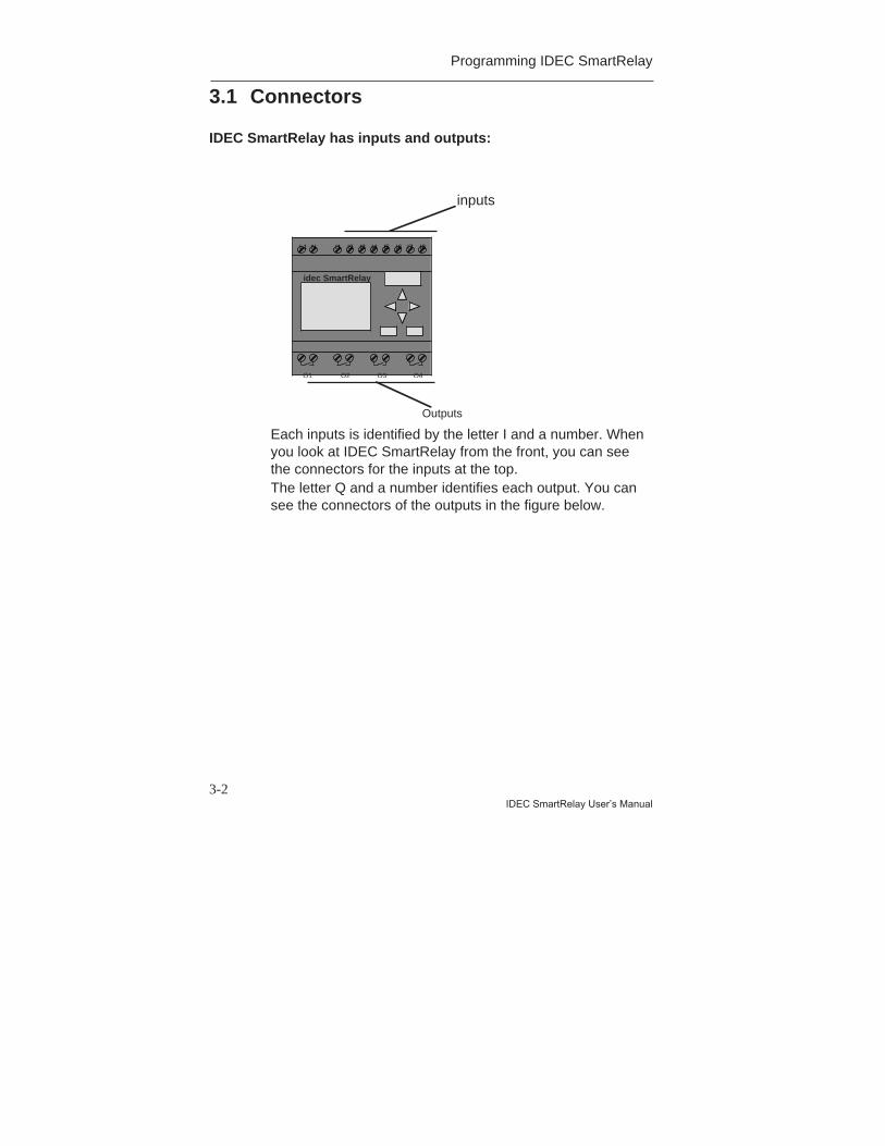
IDEC SmartRelay has inputs and outputs:
Each inputs is identified by the letter I and a number. Whenyou look at IDEC SmartRelay from the front, you can seethe connectors for the inputs at the top.The letter Q and a number identifies each output. You cansee the connectors of the outputs in the figure below.
L1 N I1 I2 I3 I4 I5 I6
Q1 Q2 Q3 Q4
I7 I8
inputs
Outputs
idec SmartRelay
Programming IDEC SmartRelay
3-3
IDEC SmartRelay User’s Manual
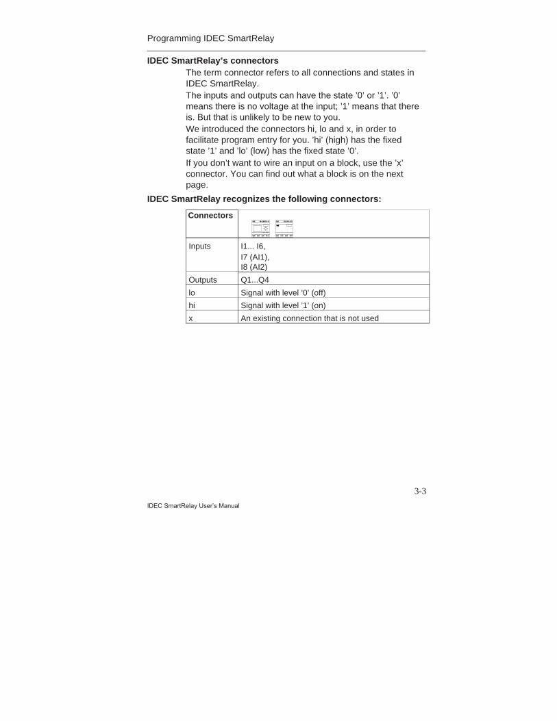
IDEC SmartRelay’s connectorsThe term connector refers to all connections and states inIDEC SmartRelay.The inputs and outputs can have the state ’0’ or ’1’. ’0’means there is no voltage at the input; ’1’ means that thereis. But that is unlikely to be new to you.We introduced the connectors hi, lo and x, in order tofacilitate program entry for you. ’hi’ (high) has the fixedstate ’1’ and ’lo’ (low) has the fixed state ’0’.If you don’t want to wire an input on a block, use the ’x’connector. You can find out what a block is on the nextpage.
IDEC SmartRelay recognizes the following connectors:
Connectors
Inputs I1... I6,I7 (AI1),I8 (AI2)
Outputs Q1...Q4
lo Signal with level ’0’ (off)
hi Signal with level ’1’ (on)
x An existing connection that is not used
Programming IDEC SmartRelay
3-4IDEC SmartRelay User’s Manual
3.2 Blocks and Block Numbers
In this chapter, we will describe how you can createextensive circuits with the aid of IDEC SmartRelay’selements and how the blocks are linked to each other andto the inputs and outputs.For this purpose, please turn to Section 3.3. There wedescribe how to turn a conventional circuit into a IDECSmartRelay program.
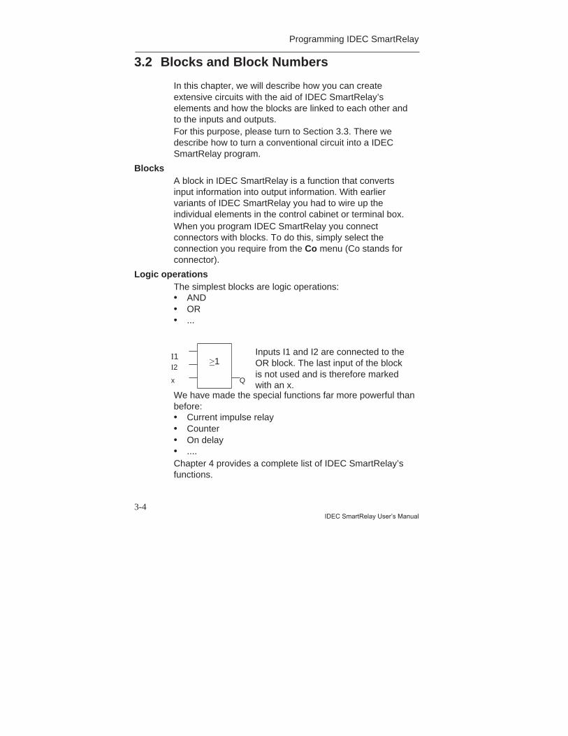
BlocksA block in IDEC SmartRelay is a function that convertsinput information into output information. With earliervariants of IDEC SmartRelay you had to wire up theindividual elements in the control cabinet or terminal box.When you program IDEC SmartRelay you connectconnectors with blocks. To do this, simply select theconnection you require from the Co menu (Co stands forconnector).
Logic operationsThe simplest blocks are logic operations:• AND• OR• ...
We have made the special functions far more powerful thanbefore:• Current impulse relay• Counter• On delay• ....Chapter 4 provides a complete list of IDEC SmartRelay’sfunctions.
I1I2
x
>1
Q
Inputs I1 and I2 are connected to theOR block. The last input of the blockis not used and is therefore markedwith an x.
Programming IDEC SmartRelay
3-5
IDEC SmartRelay User’s Manual
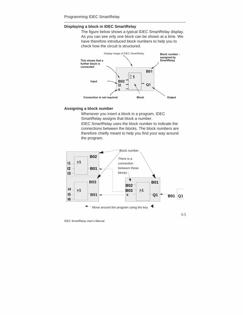
Displaying a block in IDEC SmartRelayThe figure below shows a typical IDEC SmartRelay display.As you can see only one block can be shown at a time. Wehave therefore introduced block numbers to help you tocheck how the circuit is structured.
B02 > 1
I2 Q1
B01
x
Display image of SmartRelay Block number - assigned by SmartRelay This shows that a
further block is connected
Input
Connection is not required Output Block
Assigning a block numberWhenever you insert a block in a program, IDECSmartRelay assigns that block a number.IDEC SmartRelay uses the block number to indicate theconnections between the blocks. The block numbers aretherefore chiefly meant to help you find your way aroundthe program.
I1I2I3
B01
B02
B02B03
Q1
B01
B01
Move around the program using the key
I4I5I6
B01
There is a
connection
between these
blocks
Block number
Q1x
B03
>1>1
>1
Display image of IDEC SmartRelay
Programming IDEC SmartRelay
3-6IDEC SmartRelay User’s Manual
The overview display shows you three displays of IDECSmartRelay, which together make up the program. As youcan see IDEC SmartRelay links the blocks with oneanother by means of the block numbers.
Advantages of the block numbersYou can connect almost any block to an input of the currentblock using its block number. In this way you can use theinterim results of logic or other operations more than once.This saves you the work required to enter things again aswell as memory space, and ensures that your circuitremains clear.
Note
To make working with IDEC SmartRelay particularly efficient, we
recommend that you draw up a diagram overview of the program.
This will make it easier to create the program. You can then enter
the block numbers assigned by IDEC SmartRelay in this diagram.
If you use the WindLGC to program IDEC SmartRelay, you can
display and print out a ladder program. You can create a
functional block diagram of your program immediately using
WindLGC.
Programming IDEC SmartRelay
3-7
IDEC SmartRelay User’s Manual
3.3 From the Circuit Diagram to IDECSmartRelay
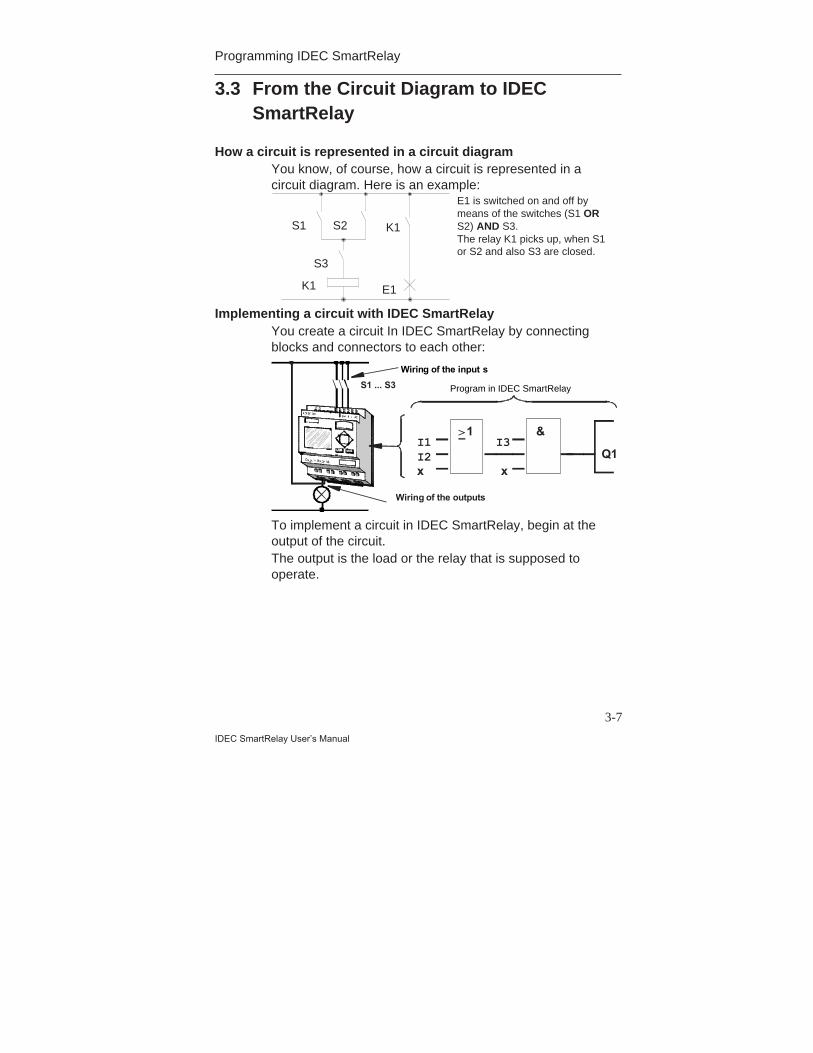
How a circuit is represented in a circuit diagramYou know, of course, how a circuit is represented in acircuit diagram. Here is an example:
Implementing a circuit with IDEC SmartRelayYou create a circuit In IDEC SmartRelay by connectingblocks and connectors to each other:
S1 ... S3
Wiring of the input s
I3
x Q1
& > 1 I1 I2 x
Program in SmartRelay
Wiring of the outputs
To implement a circuit in IDEC SmartRelay, begin at theoutput of the circuit.The output is the load or the relay that is supposed tooperate.
K1
S1 K1S2
E1
E1 is switched on and off bymeans of the switches (S1 ORS2) AND S3.The relay K1 picks up, when S1or S2 and also S3 are closed.
S3
Program in IDEC SmartRelay
Programming IDEC SmartRelay
3-8IDEC SmartRelay User’s Manual
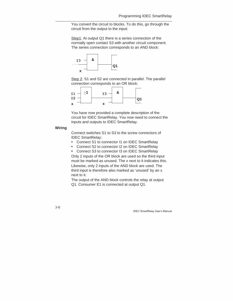
You convert the circuit to blocks. To do this, go through thecircuit from the output to the input:
Step1: At output Q1 there is a series connection of thenormally open contact S3 with another circuit component.The series connection corresponds to an AND block:
Step 2: S1 and S2 are connected in parallel. The parallelconnection corresponds to an OR block:
You have now provided a complete description of thecircuit for IDEC SmartRelay. You now need to connect theinputs and outputs to IDEC SmartRelay.
WiringConnect switches S1 to S3 to the screw connectors ofIDEC SmartRelay:• Connect S1 to connector I1 on IDEC SmartRelay• Connect S2 to connector I2 on IDEC SmartRelay• Connect S3 to connector I3 on IDEC SmartRelayOnly 2 inputs of the OR block are used so the third inputmust be marked as unused. The x next to it indicates this.Likewise, only 2 inputs of the AND block are used. Thethird input is therefore also marked as ’unused’ by an xnext to it.The output of the AND block controls the relay at outputQ1. Consumer E1 is connected at output Q1.
I3
xQ1
&
I3I2
xQ1
&>1I1
x
Programming IDEC SmartRelay
3-9
IDEC SmartRelay User’s Manual
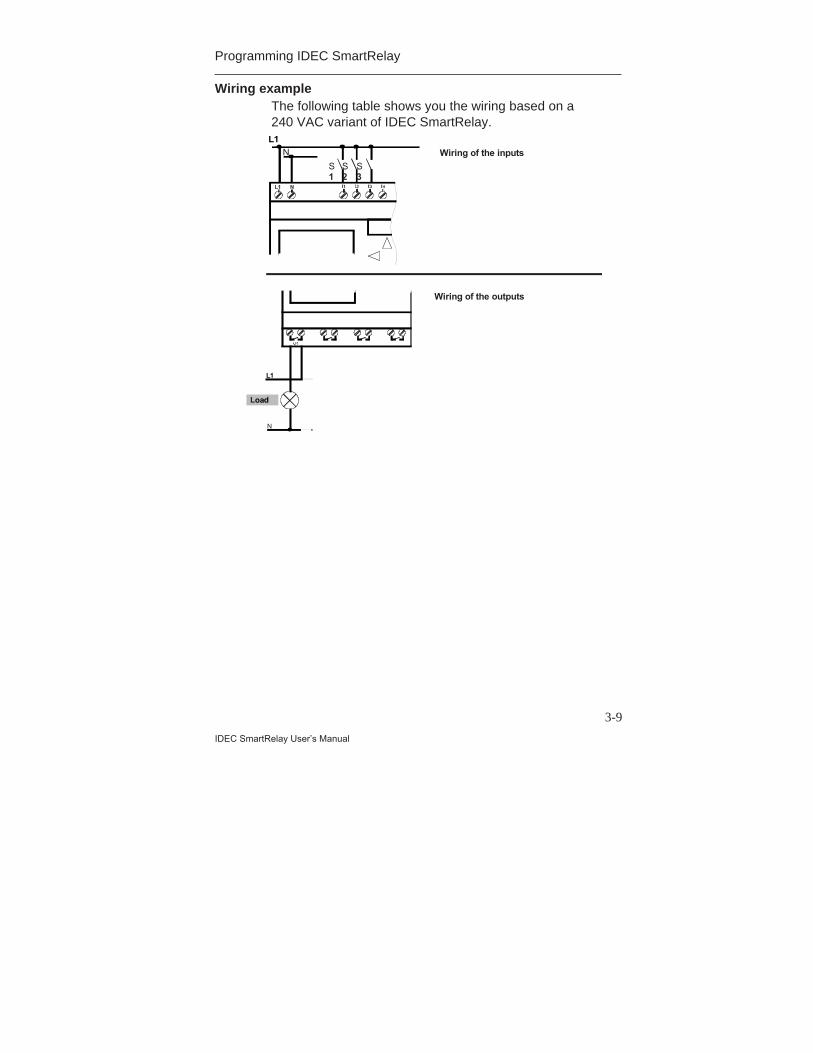
Wiring exampleThe following table shows you the wiring based on a240 VAC variant of IDEC SmartRelay.
Load
L1
N
S1
S3
S2
L1
N
Wiring of the inputs
Wiring of the outputs
L1 N
Programming IDEC SmartRelay
3-10IDEC SmartRelay User’s Manual
3.4 The 4 Golden Rules for Working withIDEC SmartRelay
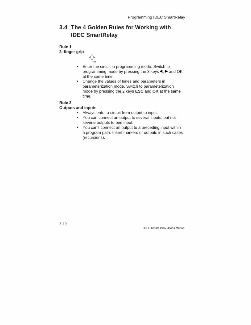
Rule 13–finger grip
• Enter the circuit in programming mode. Switch toprogramming mode by pressing the 3 keys , and OKat the same time.
• Change the values of times and parameters inparameterization mode. Switch to parameterizationmode by pressing the 2 keys ESC and OK at the sametime.
Rule 2Outputs and inputs
• Always enter a circuit from output to input.• You can connect an output to several inputs, but not
several outputs to one input.• You can’t connect an output to a preceding input within
a program path. Insert markers or outputs in such cases(recursions).
OK
Programming IDEC SmartRelay
3-11
IDEC SmartRelay User’s Manual
Rule 3Cursor and cursor movement
The following applies when entering a circuit:• When the cursor appears in the form of an underscore,
you can move the cursor:- Use the keys , , or to move the cursor in the
circuit.- Press OK to select a connector/block.- Press ESC to exit circuit input.
• When the cursor appears in the form of a solid block,you should select a connector/block- Use the keys or to select a connector/block.- Press OK to accept a selection.- Press ESC to go back one step.
Rule 4Planning
• Before you enter a circuit, draw up a complete plan of iton paper or program IDEC SmartRelay directly usingWindLGC.
• IDEC SmartRelay can only store complete programs. Ifyou enter an incomplete program, IDEC SmartRelay isnot able to exit Programming mode.
Programming IDEC SmartRelay
3-12IDEC SmartRelay User’s Manual
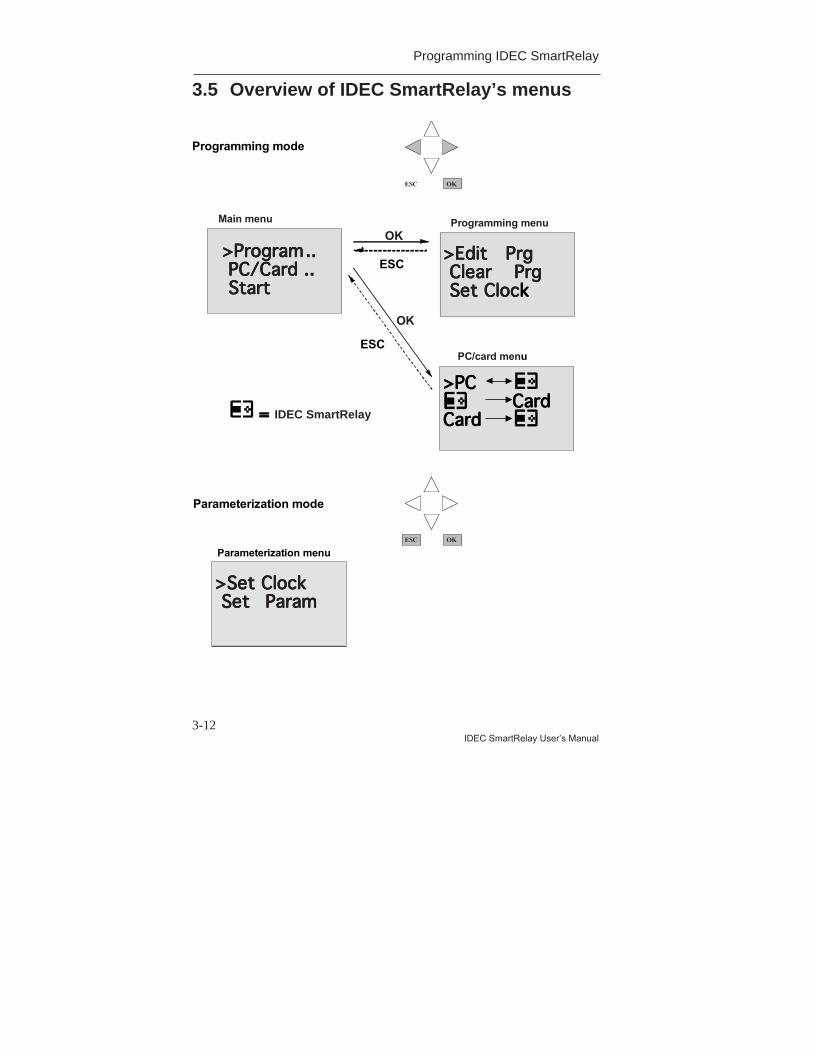
3.5 Overview of IDEC SmartRelay’s menus
>>>>PPPPrrrrooooggggrrrraaaammmm........ PPPPCCCC////CCCCaaaarrrrdddd ........ SSSSttttaaaarrrrtttt
>>>>EEEEddddiiiitttt PPPPrrrrgggg CCCClllleeeeaaaarrrr PPPPrrrrgggg SSSSeeeetttt CCCClllloooocccckkkk
>>>>PPPPCCCCCCCCaaaarrrrdddd
CCCCaaaarrrrdddd
Main menu Programming menu
PC/card menu
>>>>SSSSeeeetttt CCCClllloooocccckkkk SSSSeeeetttt PPPPaaaarrrraaaammmm
OK
OK
ESC
ESC
Parameterization menu
Programming mode
Parameterization mode
==== SmartRelay
OKESC
OKESC
IDEC SmartRelay
Programming IDEC SmartRelay
3-13
IDEC SmartRelay User’s Manual
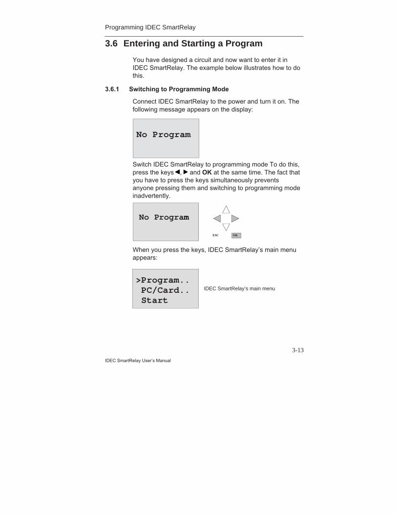
3.6 Entering and Starting a Program
You have designed a circuit and now want to enter it inIDEC SmartRelay. The example below illustrates how to dothis.
3.6.1 Switching to Programming Mode
Connect IDEC SmartRelay to the power and turn it on. Thefollowing message appears on the display:
Switch IDEC SmartRelay to programming mode To do this,press the keys , and OK at the same time. The fact thatyou have to press the keys simultaneously preventsanyone pressing them and switching to programming modeinadvertently.
No Program
OKESC
When you press the keys, IDEC SmartRelay’s main menuappears:
>Program.. PC/Card.. Start
IDEC SmartRelay’s main menu
No Program

Programming IDEC SmartRelay
3-14IDEC SmartRelay User’s Manual
On the left in the first line you will see ”>”. Use the keys and to move the ”>” up and down. Move the ”>” to”Program..” and press OK. IDEC SmartRelay switches tothe programming menu.
Here too, you can move the ”>” by pressing the and keys. Position the ”>” on ”Edit Prg” (i.e. to enter theprogram) and press OK. Smart Relay then displays the firstoutput:
Use the and keys to select the other outputs. At thispoint, you begin to enter your circuit.
3.6.2 First Program
Let’s have a look at the following circuit: a parallelconnection of two switches.
Circuit diagramHow a circuit is represented in a circuit diagram
>Edit PrgClear PrgSet Clock
IDEC SmartRelay’s programming
Q1IDEC SmartRelay’s first output
K1
S1K1
S2
E1
Switch S1 or switch S2switches on E1. With IDECSmartRelay, the parallelconnection of the switches isan OR block because S1 orS2 switches the output on.
Programming IDEC SmartRelay
3-15
IDEC SmartRelay User’s Manual
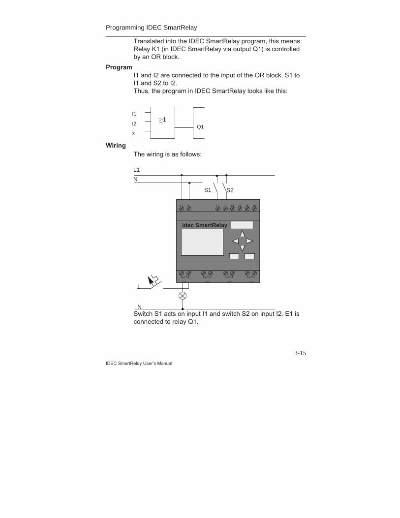
Translated into the IDEC SmartRelay program, this means:Relay K1 (in IDEC SmartRelay via output Q1) is controlledby an OR block.
ProgramI1 and I2 are connected to the input of the OR block, S1 toI1 and S2 to I2.Thus, the program in IDEC SmartRelay looks like this:
WiringThe wiring is as follows:
Switch S1 acts on input I1 and switch S2 on input I2. E1 isconnected to relay Q1.
I1
I2
xQ1
>1
L1 N I1 I2 I3 I4 I5 I6
Q1 Q2 Q3 Q4
L1
N
S1 S2
L
N
idec SmartRelay
Programming IDEC SmartRelay
3-16IDEC SmartRelay User’s Manual
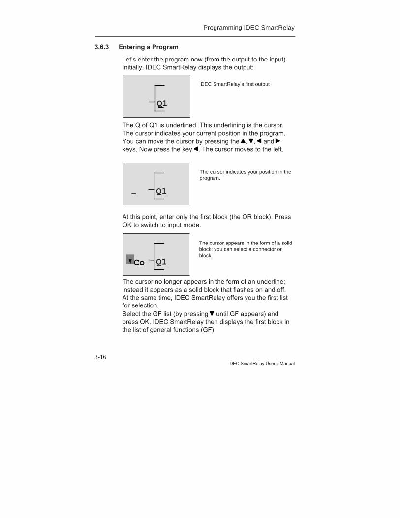
3.6.3 Entering a Program
Let’s enter the program now (from the output to the input).Initially, IDEC SmartRelay displays the output:
The Q of Q1 is underlined. This underlining is the cursor.The cursor indicates your current position in the program.You can move the cursor by pressing the , , and keys. Now press the key . The cursor moves to the left.
At this point, enter only the first block (the OR block). PressOK to switch to input mode.
The cursor no longer appears in the form of an underline;instead it appears as a solid block that flashes on and off.At the same time, IDEC SmartRelay offers you the first listfor selection.Select the GF list (by pressing until GF appears) andpress OK. IDEC SmartRelay then displays the first block inthe list of general functions (GF):
IDEC SmartRelay’s first output
Q1
The cursor indicates your position in theprogram.
Q1-
The cursor appears in the form of a solidblock: you can select a connector orblock.
Q1Co
Programming IDEC SmartRelay
3-17
IDEC SmartRelay User’s Manual
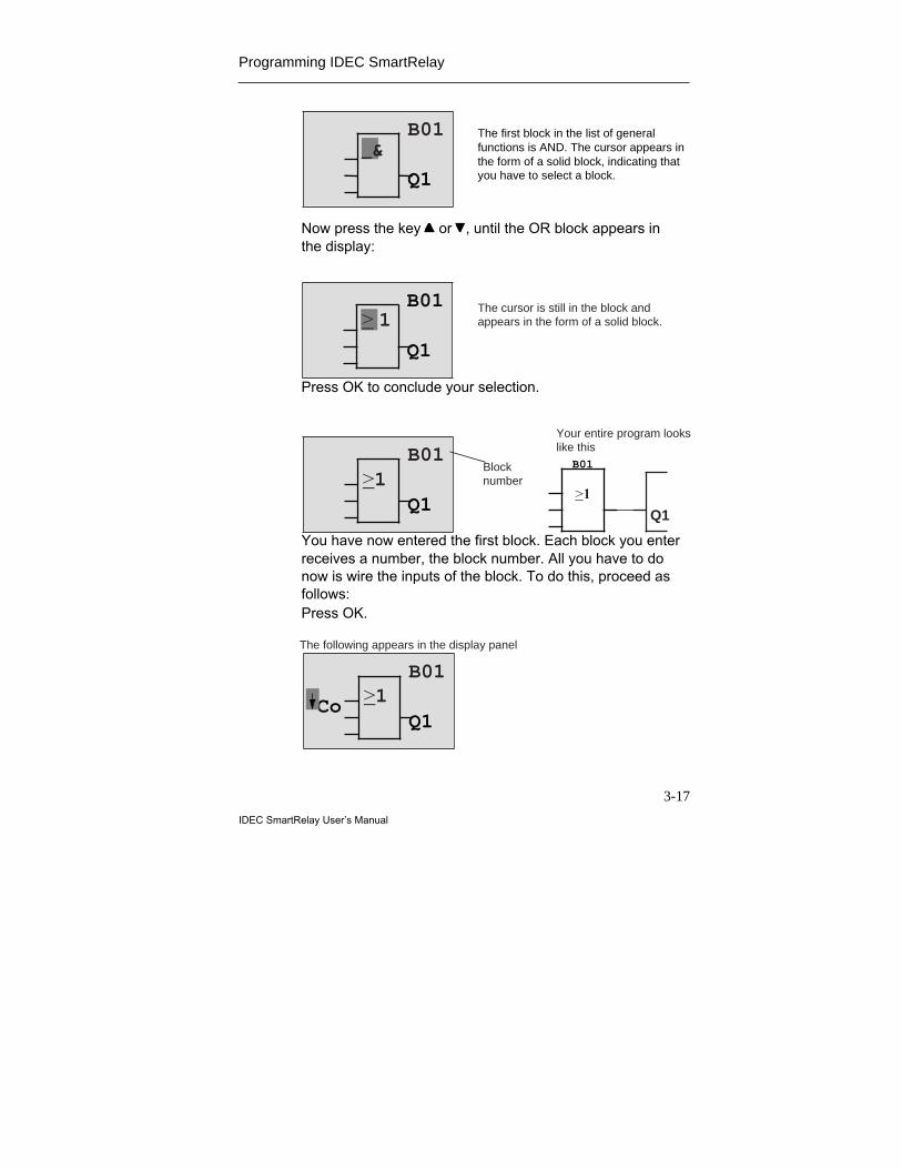
Now press the key or , until the OR block appears inthe display:
Press OK to conclude your selection.
You have now entered the first block. Each block you enterreceives a number, the block number. All you have to donow is wire the inputs of the block. To do this, proceed asfollows:Press OK.
> 1B01
Q1
The cursor is still in the block andappears in the form of a solid block.
The first block in the list of generalfunctions is AND. The cursor appears inthe form of a solid block, indicating thatyou have to select a block.
B01
Q1
>1B01
Q1
B01
>1
Q1
Your entire program lookslike this
Blocknumber
>1
The following appears in the display panel
B01
Q1Co
_&
Programming IDEC SmartRelay
3-18IDEC SmartRelay User’s Manual
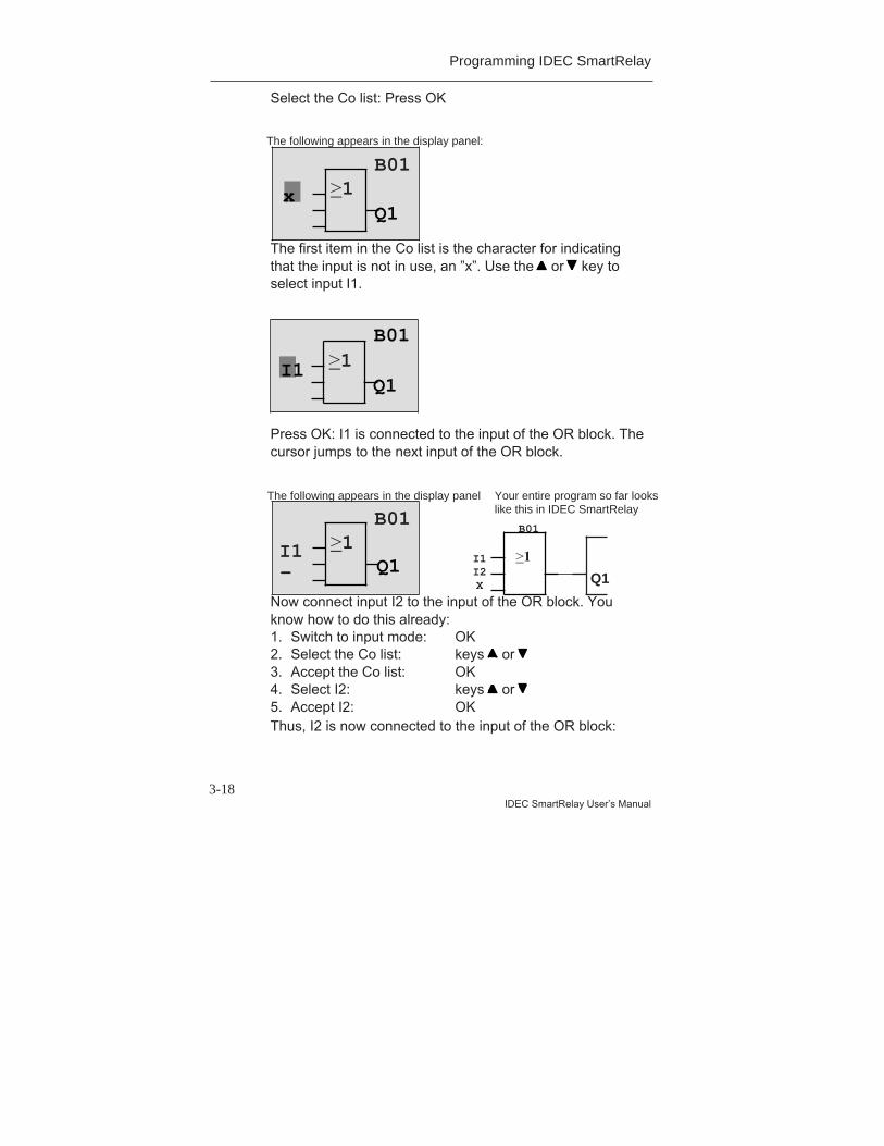
Select the Co list: Press OK
The first item in the Co list is the character for indicatingthat the input is not in use, an ”x”. Use the or key toselect input I1.
Press OK: I1 is connected to the input of the OR block. Thecursor jumps to the next input of the OR block.
Now connect input I2 to the input of the OR block. Youknow how to do this already:1. Switch to input mode: OK2. Select the Co list: keys or 3. Accept the Co list: OK4. Select I2: keys or 5. Accept I2: OKThus, I2 is now connected to the input of the OR block:
>1
The following appears in the display panel:
B01
Q1x
>1Q1
I1
B01
>1
The following appears in the display panel
B01
Q1Q1
Your entire program so far lookslike this in IDEC SmartRelay
I1 I1I2X
B01
->1
Programming IDEC SmartRelay
3-19
IDEC SmartRelay User’s Manual
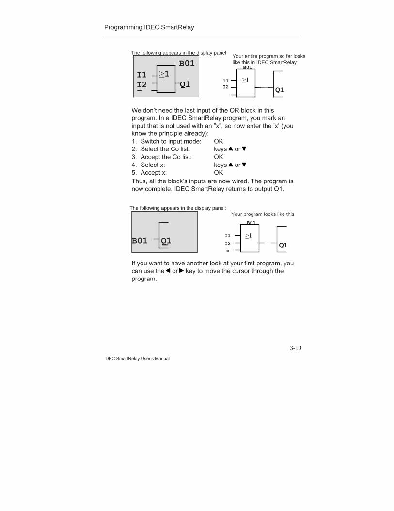
We don’t need the last input of the OR block in thisprogram. In a IDEC SmartRelay program, you mark aninput that is not used with an ”x”, so now enter the ’x’ (youknow the principle already):1. Switch to input mode: OK2. Select the Co list: keys or 3. Accept the Co list: OK4. Select x: keys or 5. Accept x: OKThus, all the block’s inputs are now wired. The program isnow complete. IDEC SmartRelay returns to output Q1.
If you want to have another look at your first program, youcan use the or key to move the cursor through theprogram.
>1
The following appears in the display panel
B01
Q1Q1
Your entire program so far lookslike this in IDEC SmartRelay
I1I2
I1I2
B01
-
The following appears in the display panel:
Q1
Your program looks like this
I1
B01
I2Q1B01x
>1
>1

Programming IDEC SmartRelay
3-20IDEC SmartRelay User’s Manual
But we are going to exit program input now. To do this,proceed as follows:1. Return to the programming menu: ESCIf this doesn’t return you to the programming menu, youhave not wired a block completely. IDEC SmartRelaydisplays the point in the program at which you forgotsomething (IDEC SmartRelay only accepts completedprograms). Also refer to page 3-33.
NoteIDEC SmartRelay has now stored your programpermanently, so that it will not be lost in the event of a powerfailure. The program is stored in IDEC SmartRelay until youexpressly delete it by entering the appropriate command.
2. Return to the main menu: ESC
Switching IDEC SmartRelay to RUN3. Move ’>’ to ’Start’: keys or 4. Accept Start: OKIDEC SmartRelay switches to RUN. In RUN IDECSmartRelay displays the following:
IDEC SmartRelay’s display panel in RUN
State of the inputs
Current time(variants with time switch only)
IDEC SmartRelay is in RUN
State of the outputs
I:123456Mo 09:00
Q:1234
Programming IDEC SmartRelay
3-21
IDEC SmartRelay User’s Manual
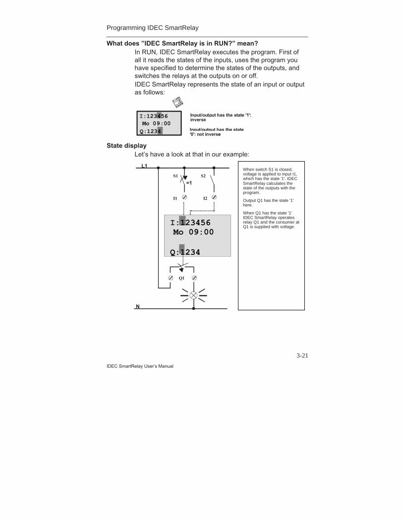
What does ”IDEC SmartRelay is in RUN?” mean?In RUN, IDEC SmartRelay executes the program. First ofall it reads the states of the inputs, uses the program youhave specified to determine the states of the outputs, andswitches the relays at the outputs on or off.IDEC SmartRelay represents the state of an input or outputas follows:
Input/output has the state '1':inverse
Input/output has the state'0': not inverse
I:123456Mo 09:00Q:1234
State displayLet’s have a look at that in our example:
I:123456Mo 09:00
Q:1234 RUN
L1
N
S1 S2
=1
When switch S1 is closed,voltage is applied to input I1,which has the state '1'.SmartRelay calculates the statesof the outputs with theprogram.Output Q1 has the state '1'here.When Q1 has the state '1',SmartRelay operates relay Q1and the consumer at Q1 issupplied with voltage.
I1 I2
Q1
When switch S1 is closed,voltage is applied to input I1,which has the state '1'. IDECSmartRelay calculates thestate of the outputs with theprogram.
Output Q1 has the state '1'here.
When Q1 has the state '1'IDEC SmartRelay operatesrelay Q1 and the consumer atQ1 is supplied with voltage.

Programming IDEC SmartRelay
3-22IDEC SmartRelay User’s Manual
The next stepYou have now successfully entered your first circuit.In the next section, we will show you how to make changesto existing programs and use special functions in them.
Programming IDEC SmartRelay
3-23
IDEC SmartRelay User’s Manual
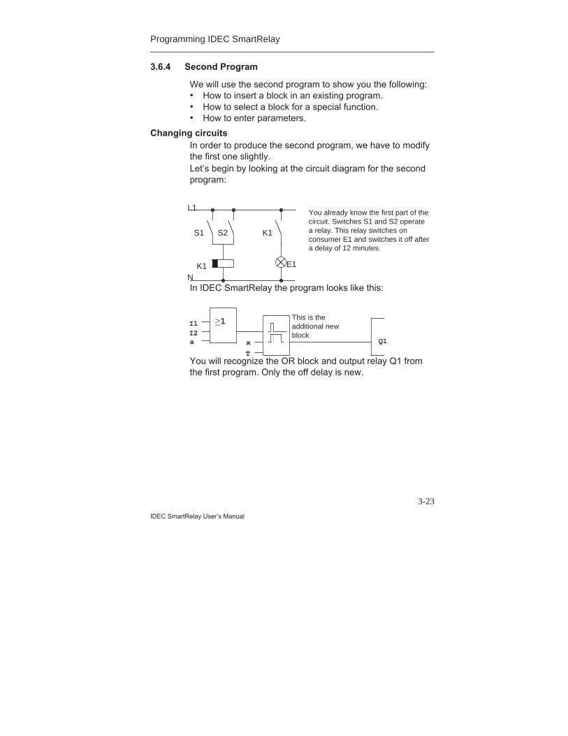
3.6.4 Second Program
We will use the second program to show you the following:• How to insert a block in an existing program.• How to select a block for a special function.• How to enter parameters.
Changing circuitsIn order to produce the second program, we have to modifythe first one slightly.Let’s begin by looking at the circuit diagram for the secondprogram:
In IDEC SmartRelay the program looks like this:
You will recognize the OR block and output relay Q1 fromthe first program. Only the off delay is new.
L1
I1I2x
N
Q1
S1 S2
You already know the first part of thecircuit. Switches S1 and S2 operatea relay. This relay switches onconsumer E1 and switches it off aftera delay of 12 minutes.
x
T
K1
K1 E1
This is theadditional newblock
>1
Programming IDEC SmartRelay
3-24IDEC SmartRelay User’s Manual
Editing a programSwitch IDEC SmartRelay to programming modeTo do this, proceed as follows:1. Switch IDEC SmartRelay to programming mode:
( , and OK at the same time).2. Select ”Program..” from the main menu
(by moving ’>’ to “Program..” and press OK)3. Select ”Edit Prg..” from the programming menu
(by moving ’>’ to “Edit Prg..” and press OK)You can now modify the existing program.
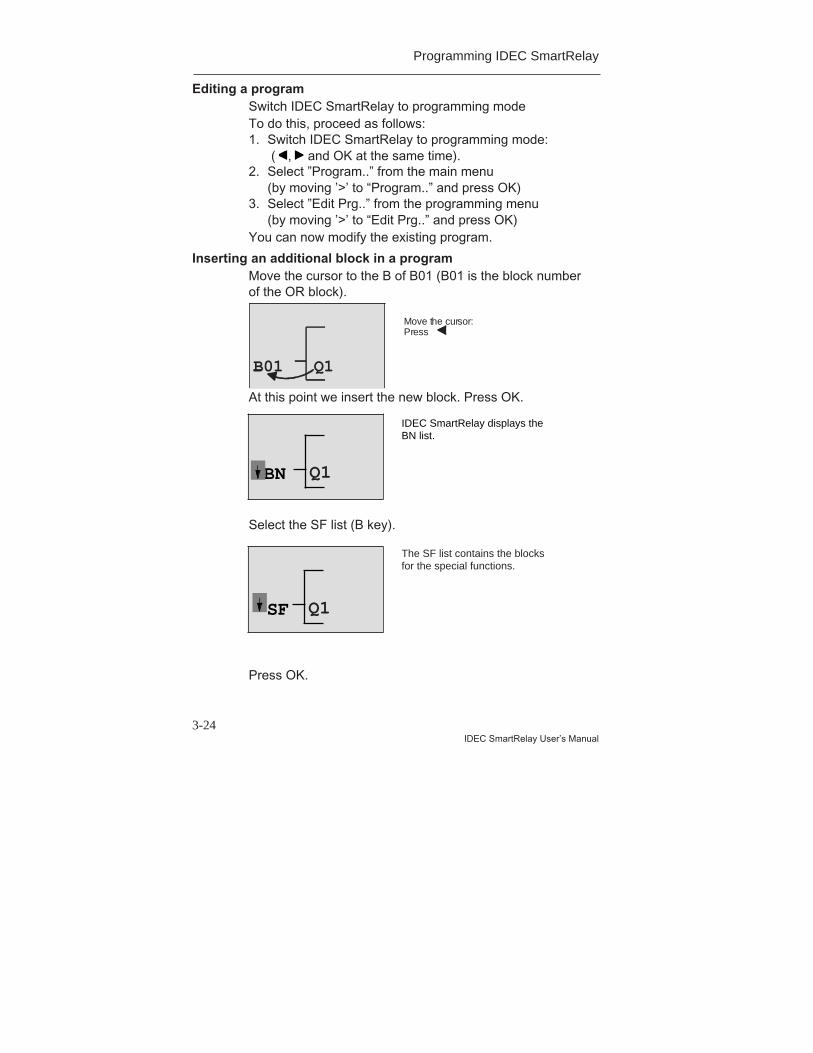
Inserting an additional block in a programMove the cursor to the B of B01 (B01 is the block numberof the OR block).
At this point we insert the new block. Press OK.
Select the SF list (B key).
Press OK.
Q1B01
Move the cursor:Press
Q1BN
The SF list contains the blocksfor the special functions.
Q1SF
IDEC SmartRelay displays theBN list.

Programming IDEC SmartRelay
3-25
IDEC SmartRelay User’s Manual
The block of the first special function appears:
Select the desired block (off delay, see next diagram) andpress OK:
TrgT Q1
When you select a block for a special orgeneral function, IDEC SmartRelay displaysthe block of the function. The cursor is in theblock and appears in the form of a solid block.Use the or key to select the block youwant.
R
The inserted block receives the block numberB02. Block B01, which has been connectedup to now to Q1, is automatically connectedto the uppermost input of the inserted block.The cursor is positioned at the uppermostinput of the inserted block.
B01
TQ1
B02
Programming IDEC SmartRelay
3-26IDEC SmartRelay User’s Manual
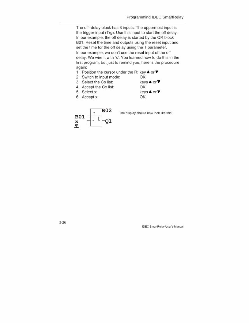
The off–delay block has 3 inputs. The uppermost input isthe trigger input (Trg). Use this input to start the off delay.In our example, the off delay is started by the OR blockB01. Reset the time and outputs using the reset input andset the time for the off delay using the T parameter.In our example, we don’t use the reset input of the offdelay. We wire it with ’x’. You learned how to do this in thefirst program, but just to remind you, here is the procedureagain:1. Position the cursor under the R: key or 2. Switch to input mode: OK3. Select the Co list: keys or 4. Accept the Co list: OK5. Select x: keys or 6. Accept x: OK
xB01
TQ1
B02The display should now look like this:

Programming IDEC SmartRelay
3-27
IDEC SmartRelay User’s Manual
Parameterizing a blockNow enter the time T for the off delay:1. If the cursor is not yet under the T,
move it there: keys or 2. Switch to input mode: OKIDEC SmartRelay displays the parameter window forparameters:
B02: the parameter of block B02T: is a time
+ means: the parameter is displayedin parameterization mode and can bemodified there
B02:TT=00:00s+
Time value Time unit
The cursor appears on the first position of the time value.To change the time value, proceed as follows:• Use the keys and to move the cursor to different
positions.• Use the keys and to change the value.• When you have entered the time value, press OK.
Setting the timeSet the time T = 12:00 minutes:1. Move the cursor to the first position:
or 2. Select ’1’:
or 3. Move the cursor to the second position:
or 4. Select ’2’:
or 5. Move the cursor to the unit:
or 6. Select the unit m for minutes:
or
Programming IDEC SmartRelay
3-28IDEC SmartRelay User’s Manual
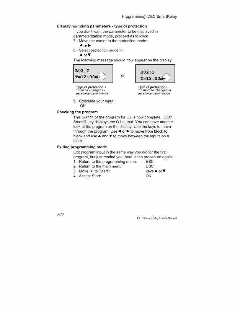
Displaying/hiding parameters - type of protectionIf you don’t want the parameter to be displayed inparameterization mode, proceed as follows:7. Move the cursor to the protection mode::
or 8. Select protection mode ’-’:
or The following message should now appear on the display:
Type ofprotection+i eT can be changed in parameterization m
Type ofprotection: TimeT cannot be changed inparameterization mode
or
Type of protection +T can be changed inparameterization mode
Type of protection -T cannot be changed inparameterization mode
B02:T
T=12:00m-
B02:T
T=12:00m+
9. Conclude your input: OK
Checking the programThis branch of the program for Q1 is now complete. IDECSmartRelay displays the Q1 output. You can have anotherlook at the program on the display. Use the keys to movethrough the program. Use or to move from block toblock and use and to move between the inputs on ablock.
Exiting programming modeExit program input in the same way you did for the firstprogram, but just remind you, here is the procedure again:1. Return to the programming menu: ESC2. Return to the main menu: ESC3. Move ’>’ to ’Start’: keys or 4. Accept Start: OK

Programming IDEC SmartRelay
3-29
IDEC SmartRelay User’s Manual
IDEC SmartRelay is now in RUN again:
I:123456
Q:1234
Mo 09:00

Programming IDEC SmartRelay
3-30IDEC SmartRelay User’s Manual
3.6.5 Deleting a Block
Let’s suppose you want to delete block B02 from thefollowing program and connect B01 directly with Q1.
Q1
I1
I2
x x
T
B01
B02
To do this, proceed as follows:1. Switch IDEC SmartRelay to programming mode
(3–finger grip).2. Select ’Edit Prg’ by pressing OK.3. Position the cursor at the input of Q1, i.e. under B02
using the key :
4. Press OK.5. Connect block B01 instead of block B02 directly to
output Q1:Select the BN list and press OKSelect B01 and press OK.
Result: Block B02 is now deleted, because it is no longerused anywhere within the entire circuit. Block B01 is nowconnected directly to the output instead of B02.
B02 Q1
Programming IDEC SmartRelay
3-31
IDEC SmartRelay User’s Manual
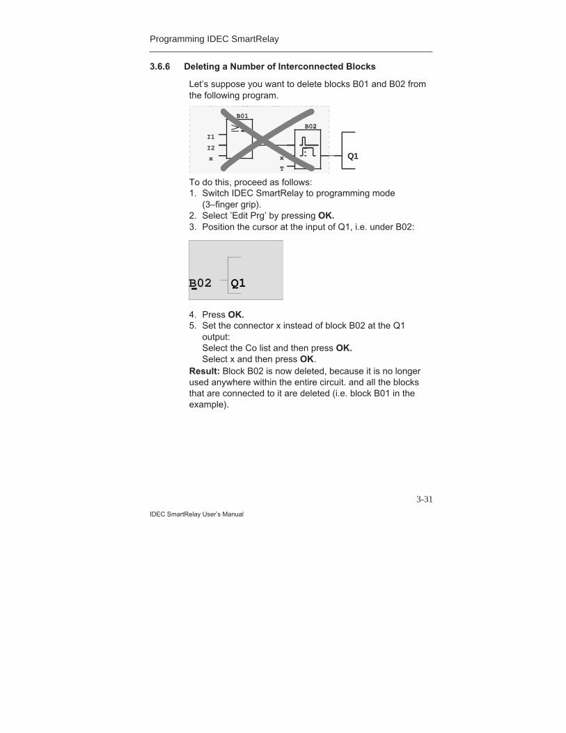
3.6.6 Deleting a Number of Interconnected Blocks
Let’s suppose you want to delete blocks B01 and B02 fromthe following program.
Q1
I1
I2
x x
T
B01
B02
To do this, proceed as follows:1. Switch IDEC SmartRelay to programming mode
(3–finger grip).2. Select ’Edit Prg’ by pressing OK.3. Position the cursor at the input of Q1, i.e. under B02:
4. Press OK.5. Set the connector x instead of block B02 at the Q1
output:Select the Co list and then press OK.Select x and then press OK.
Result: Block B02 is now deleted, because it is no longerused anywhere within the entire circuit. and all the blocksthat are connected to it are deleted (i.e. block B01 in theexample).
B02 Q1
Programming IDEC SmartRelay
3-32IDEC SmartRelay User’s Manual
3.6.7 Correcting Typing Errors
It is easy to correct typing errors in IDEC SmartRelay:• If you have not yet concluded input, you can use ESC to
go back a step.• If you have already concluded input, simply start again,
as follows:1. Move the cursor to the location of the error.2. Switch to input mode: OK3. Enter the correct wiring for the input.
You can only replace one block with another if the newblock has exactly the same number of inputs as the oldone. However, you can delete the old block and insert anew one. You can insert whichever block you like.
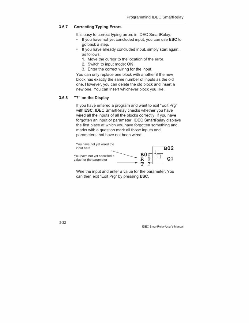
3.6.8 ”?” on the Display
If you have entered a program and want to exit “Edit Prg”with ESC, IDEC SmartRelay checks whether you havewired all the inputs of all the blocks correctly. If you haveforgotten an input or parameter, IDEC SmartRelay displaysthe first place at which you have forgotten something andmarks with a question mark all those inputs andparameters that have not been wired.
Wire the input and enter a value for the parameter. Youcan then exit “Edit Prg” by pressing ESC.
R ?
You have not yet wired theinput here
B01
T ?Q1
B02You have not yet specified avalue for the parameter
Programming IDEC SmartRelay
3-33
IDEC SmartRelay User’s Manual
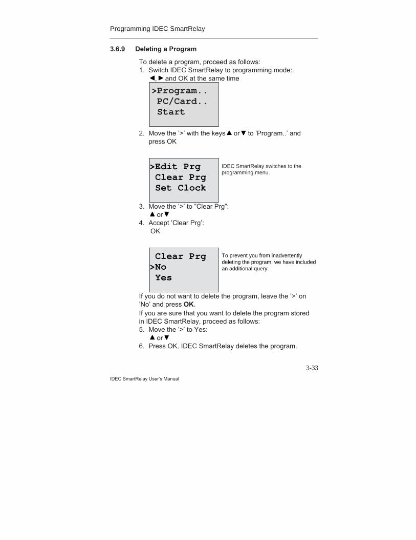
3.6.9 Deleting a Program
To delete a program, proceed as follows:1. Switch IDEC SmartRelay to programming mode:
, and OK at the same time
2. Move the ’>’ with the keys or to ’Program..’ andpress OK
3. Move the ’>’ to ”Clear Prg”: or
4. Accept ’Clear Prg’: OK
If you do not want to delete the program, leave the ’>’ on’No’ and press OK.If you are sure that you want to delete the program storedin IDEC SmartRelay, proceed as follows:5. Move the ’>’ to Yes:
or 6. Press OK. IDEC SmartRelay deletes the program.
>Program.. PC/Card.. Start
>Edit Prg Clear Prg Set Clock
Clear Prg>No Yes
IDEC SmartRelay switches to theprogramming menu.
To prevent you from inadvertentlydeleting the program, we have includedan additional query.

Programming IDEC SmartRelay
3-34IDEC SmartRelay User’s Manual
3.7 Storage Space and Size of a Circuit
A program (control program in IDEC SmartRelay, circuitdiagram) has the following limitations:• The number of blocks connected in series (nesting
depth)• The storage space (use of memory by the blocks)
Memory areaYou can only use a limited number of blocks for yourprogram in IDEC SmartRelay. In addition, some blocksrequire extra memory for their special functions.The memory required for special functions is divided upinto 4 memory areas.• Par: The area in which IDEC SmartRelay stores the
desired values (e.g. the limit values of a counter).• RAM: The area in which IDEC SmartRelay stores the
current actual values (e.g. the counter status).• Timer: The area IDEC SmartRelay uses for time
functions such as the off delay.• REM: The area in which IDEC SmartRelay stores actual
values that have to be retained (e.g. the count value ofan operating hours counter). In blocks with selective useof the retentive feature, this memory area is only used ifthe retentive feature is switched on.
Resources available in IDEC SmartRelayThe maximum amount of resources that can be occupiedby a program in IDEC SmartRelay is as follows:
Blocks Par RAM Timer REM Markers
56 48 27 16 15 8
IDEC SmartRelay monitors memory utilization, anddisplays in the function lists only those functions for whichthere is still enough memory space available.
Programming IDEC SmartRelay
3-35
IDEC SmartRelay User’s Manual
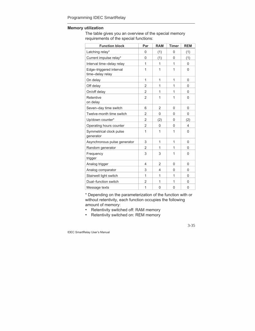
Memory utilizationThe table gives you an overview of the special memoryrequirements of the special functions:
Function block Par RAM Timer REM
Latching relay* 0 (1) 0 (1)
Current impulse relay* 0 (1) 0 (1)
Interval time–delay relay 1 1 1 0
Edge–triggered intervaltime–delay relay
1 1 1 0
On delay 1 1 1 0
Off delay 2 1 1 0
On/off delay 2 1 1 0
Retentiveon delay
2 1 1 0
Seven–day time switch 6 2 0 0
Twelve-month time switch 2 0 0 0
Up/down counter* 2 (2) 0 (2)
Operating hours counter 2 0 0 4
Symmetrical clock pulsegenerator
1 1 1 0
Asynchronous pulse generator 3 1 1 0
Random generator 2 1 1 0
Frequencytrigger
3 3 1 0
Analog trigger 4 2 0 0
Analog comparator 3 4 0 0
Stairwell light switch 1 1 1 0
Dual–function switch 2 1 1 0
Message texts 1 0 0 0
* Depending on the parameterization of the function with orwithout retentivity, each function occupies the followingamount of memory:• Retentivity switched off: RAM memory• Retentivity switched on: REM memory
Programming IDEC SmartRelay
3-36IDEC SmartRelay User’s Manual
The maximum number of functions that can be used:
The memory requirements of individual specialfunctions determine the maximum number of specialfunctions you can use.Example: The operating hours counter requires 2 memoryareas for desired value storage (Par) and 4 memory areasfor the actual values that have to be retained (REM). Thereare 15 REM memory areas and 48 Par memory areas InIDEC SmartRelay.The special function of the operating hours counter cantherefore only be used a maximum of 3 times, leaving just3 REM memory areas left. Although there are still 42 Parmemory areas free, you are one REM memory area shortto run an additional operating hours counter.Calculation: Free memory areas divided by the requirednumber of memory areas. Carry out this calculation foreach memory area required (Par, RAM, timer, REM). Thelowest value shows you the maximum number of functionsyou can use.
Nesting depthA program path consists of a series of function blocksstarting and ending with a terminal block. The number ofblocks in a program path describes the nesting depth.Inputs and levels (I, Ia, hi, lo), as well as outputs andmarkers (Q, Qa, M) are terminal blocks . The terminalblocks are not represented by a block symbol in IDECSmartRelay.The maximum number of function blocks you can use inIDEC SmartRelay is 56, so the maximum nesting depth is:56 function blocks + 2 terminal blocks = 58.
4-1IDEC SmartRelay User’s Manual
4 IDEC SmartRelay FunctionsElement lists
IDEC SmartRelay offers you a number of elements inprogramming mode. So that you don’t lose track of things,we have divided these elements into lists. These lists are:• ±Co: List of connectors (Connector)
(see Section 4.1)• ±GF: List of the general functions AND, OR, ...
(see Section 4.2)• ±SF: List of special functions
(see Section 4.4)• ±BN: List of the completed and reusable blocks in the
circuit
Contents of the listsAll the lists display elements available in IDEC SmartRelay.Normally, these are all the connectors, all the generalfunctions and all the special functions that the respectiveIDEC SmartRelay variant knows. These elements alsoinclude all the blocks you have created in IDECSmartRelay before you call up the ±BN list.
When IDEC SmartRelay no longer displays everythingIDEC SmartRelay no longer displays all elements if:• No further block must be inserted.
In this case, there is either no more memory available orthe maximum number of possible blocks has beenreached (56).
• A special block would use more memory than is stillavailable in IDEC SmartRelay.
• The resulting number of function blocks connected inseries would exceed 7 (see Section 3.7).
IDEC SmartRelay Functions
4-2IDEC SmartRelay User’s Manual
4.1 Constants and Connectors - Co
Constants and connectors (connectors = Co) are inputs,outputs, memory markers and fixed voltage levels(constants).
InputsInputs are identified by the letter I. The input numbers (I1,I2, ...) correspond to the numbers of the input connectorson IDEC SmartRelay.
Analog inputsThe IDEC SmartRelay models FL1A-H12SND, FL1A-H12RCE and FL1A-B12RCE include the inputs I7 and I8,which can also be used as AI1 and AI2, depending on howthey are programmed. If the inputs are used as I7 and I8,the signal applied is interpreted as a digital value. If theyare used as AI1 and AI2, the signals are interpreted asanalog values. In the case of special functions, which canonly be effectively connected with analog inputs on theinput side, only the analog inputs AI1 and AI2 are offeredfor selection in programming mode when the input signal isselected.
OutputsOutputs are identified by the letter Q. The output numbers(Q1, Q2, ...) correspond to the numbers of the outputconnectors on IDEC SmartRelay.
IDEC SmartRelay Functions
4-3IDEC SmartRelay User’s Manual
MarkersMarkers are identified by the letter M. Markers are virtualoutputs that have the same value at their output as theyhave at their input. There are 8 memory markers (M1 ...M8) available in IDEC SmartRelay.By using memory markers you can exceed the maximumnumber of consecutive blocks.
Startup flagsMemory marker M8 is set in the first cycle of the userprogram and can be used subsequently in your program asa startup flag. It is automatically reset after the first cycle ofprogram processing.In setting, deletion and evaluation, memory marker M8 canbe used in the same way as memory markers M1 to M7 inall subsequent cycles.
Note The signal applied at the marker's output is always that of
the last program cycle. The signal is not changed within a program cycle.
LevelsVoltage levels are identified by hi and lo. If a block issupposed to have the state “1” = hi or “0” = continuously,the input is wired with the fixed level or the constant hi or lovalue.
Open connectorsIf a connector pin of a block is not to be wired, this isindicated with an x.

IDEC SmartRelay Functions
4-4IDEC SmartRelay User’s Manual
4.2 List of General Functions - GF
General functions are basic operation links in Booleanalgebra.When you enter a circuit, you will find the blocks for generalfunctions in the GF list. The following general functionsexist:
Circuit diagramrepresentation
Representation inIDEC SmartRelay
Designation of thegeneral function
Series connectionof normally opencontacts
AND
(see page 4-6)
AND with RLO edgedetection
(see page 4-6)
Parallel connec -tion of normallyclosed contacts
NAND(AND not)
(see page 4-7)
NAND with RLOedge detection
(see page 4-8)
Parallel connec -tion of normallyopen contacts
OR
(see page 4-8)
Series connec -tionof normallyclosed contacts
NOR(OR not)
(see page 4-9)
IDEC SmartRelay Functions
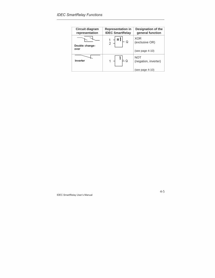
4-5IDEC SmartRelay User’s Manual
Circuit diagramrepresentation
Representation inIDEC SmartRelay
Designation of thegeneral function
Double change-over
XOR(exclusive OR)
(see page 4-10)
InverterNOT(negation, inverter)
(see page 4-10)
IDEC SmartRelay Functions
4-6IDEC SmartRelay User’s Manual
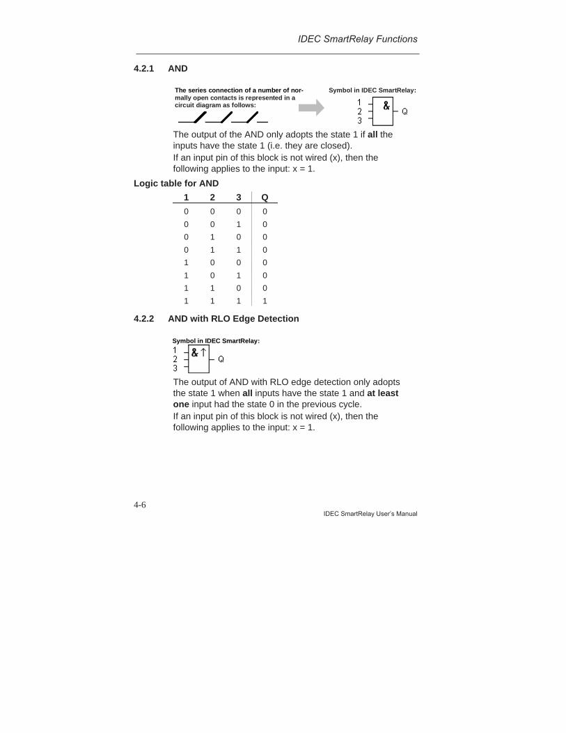
4.2.1 AND
The series connection of a number of nor-mally open contacts is represented in acircuit diagram as follows:
Symbol in IDEC SmartRelay:
The output of the AND only adopts the state 1 if all theinputs have the state 1 (i.e. they are closed).If an input pin of this block is not wired (x), then thefollowing applies to the input: x = 1.
Logic table for AND
1 2 3 Q
0 0 0 0
0 0 1 0
0 1 0 0
0 1 1 0
1 0 0 0
1 0 1 0
1 1 0 0
1 1 1 1
4.2.2 AND with RLO Edge Detection
Symbol in IDEC SmartRelay:
The output of AND with RLO edge detection only adoptsthe state 1 when all inputs have the state 1 and at leastone input had the state 0 in the previous cycle.If an input pin of this block is not wired (x), then thefollowing applies to the input: x = 1.
IDEC SmartRelay Functions
4-7IDEC SmartRelay User’s Manual
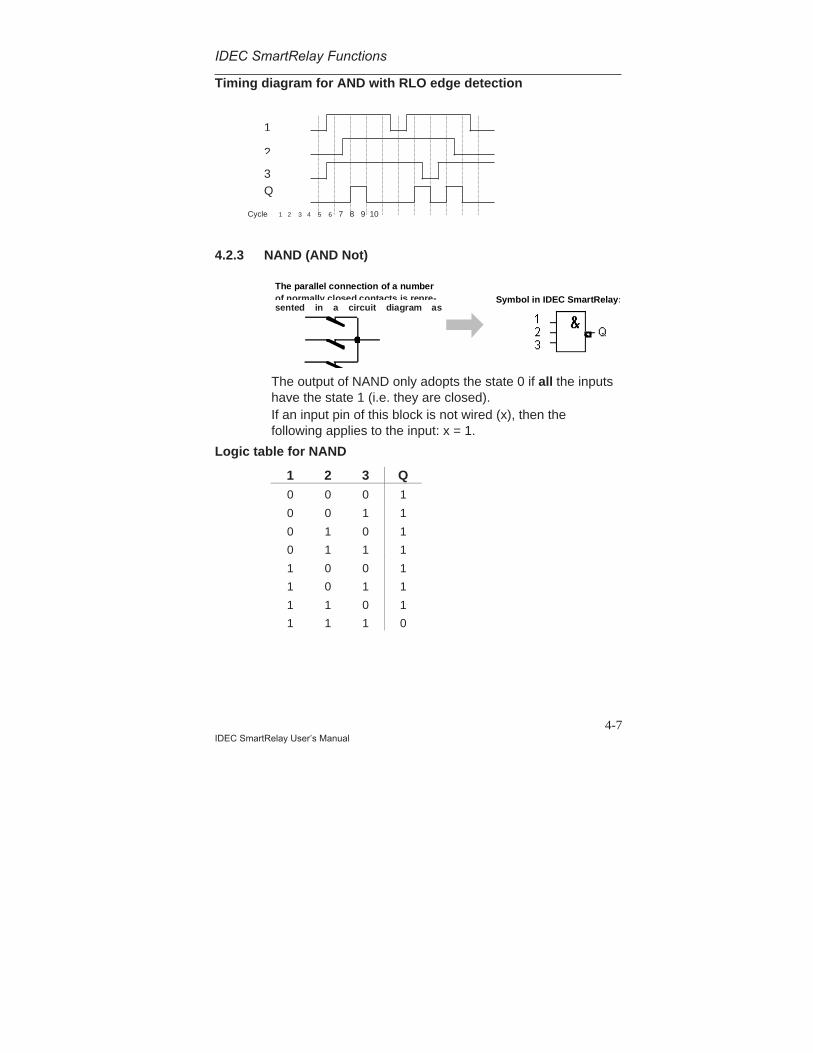
Timing diagram for AND with RLO edge detection
4.2.3 NAND (AND Not)
The parallel connection of a numberof normally closed contacts is repre-sented in a circuit diagram as
Symbol in IDEC SmartRelay:
The output of NAND only adopts the state 0 if all the inputshave the state 1 (i.e. they are closed).If an input pin of this block is not wired (x), then thefollowing applies to the input: x = 1.
Logic table for NAND
1 2 3 Q0 0 0 1
0 0 1 1
0 1 0 1
0 1 1 1
1 0 0 1
1 0 1 1
1 1 0 1
1 1 1 0
1
3 Q
2
Cycle 1 2 3 4 5 6 7 8 9 10

IDEC SmartRelay Functions
4-8IDEC SmartRelay User’s Manual
4.2.4 NAND with RLO Edge Detection
Symbol in IDEC SmartRelay:
The output of NAND with RLO edge detection only adoptsthe state 1 when at least one input has the state 0 and allinputs had the state 1 in the previous cycle.If an input pin of this block is not wired (x), then thefollowing applies to the input: x = 1.
Timing diagram for NAND with RLO edge detection
4.2.5 OR
The parallel connection of a number ofnormally open contacts is representedin a circuit diagram as follows:
Symbol in IDEC SmartRelay:
The output of the OR adopts the state 1 if at least oneinput has the state 1 (i.e. it is closed).If an input pin of this block is not wired (x), then thefollowing applies to the input: x = 0.
1
3
Q
2
Cycle 1 2 3 4 5 6 7 8 9 10
IDEC SmartRelay Functions
4-9IDEC SmartRelay User’s Manual
Logic table for OR:
1 2 3 Q0 0 0 0
0 0 1 1
0 1 0 1
0 1 1 1
1 0 0 1
1 0 1 1
1 1 0 1
1 1 1 1
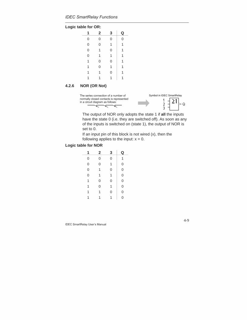
4.2.6 NOR (OR Not)
The series connection of a number of normally closed contacts is represented in a circuit diagram as follows:
Symbol in SmartRelay:
The output of NOR only adopts the state 1 if all the inputshave the state 0 (i.e. they are switched off). As soon as anyof the inputs is switched on (state 1), the output of NOR isset to 0.If an input pin of this block is not wired (x), then thefollowing applies to the input: x = 0.
Logic table for NOR
1 2 3 Q0 0 0 1
0 0 1 0
0 1 0 0
0 1 1 0
1 0 0 0
1 0 1 0
1 1 0 0
1 1 1 0
Symbol in IDEC SmartRelay
IDEC SmartRelay Functions
4-10IDEC SmartRelay User’s Manual
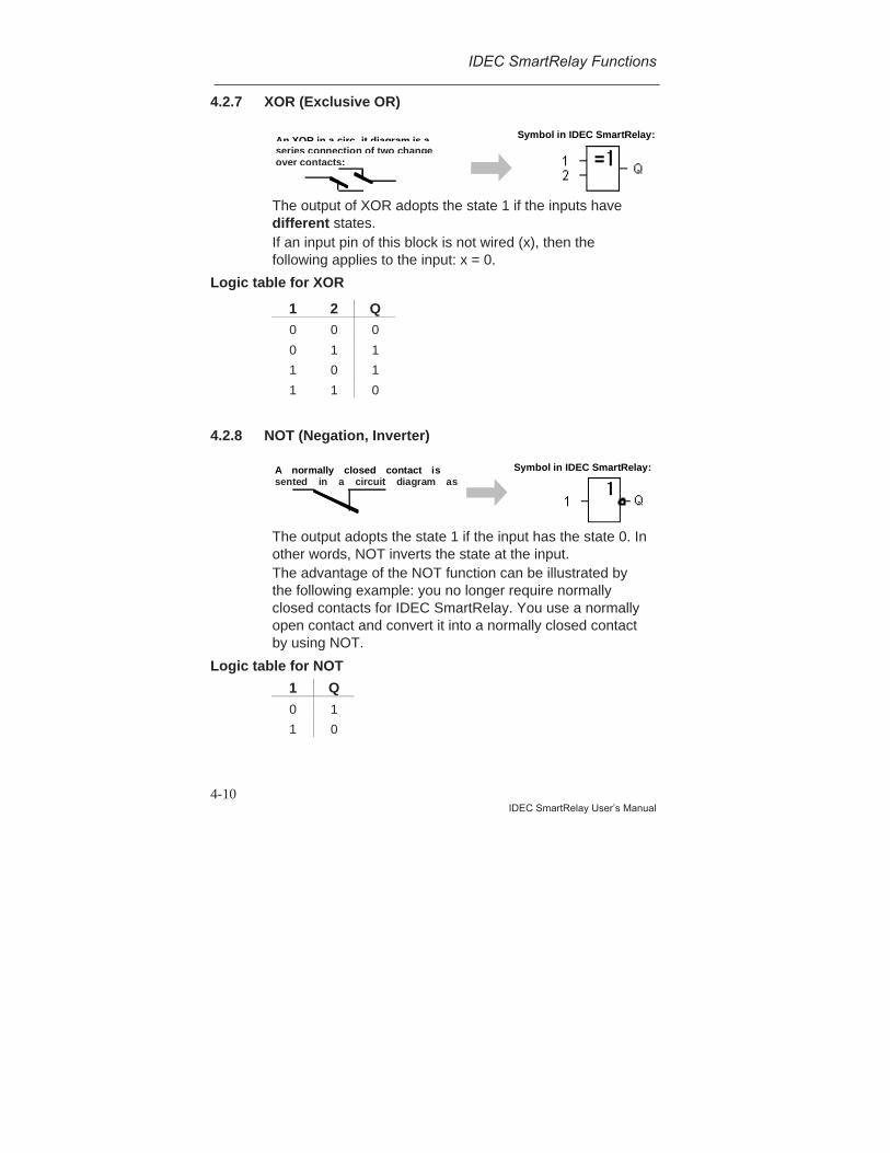
4.2.7 XOR (Exclusive OR)
An XOR in a circ it diagram is aseries connection of two changeover contacts:
Symbol in IDEC SmartRelay:
The output of XOR adopts the state 1 if the inputs havedifferent states.If an input pin of this block is not wired (x), then thefollowing applies to the input: x = 0.
Logic table for XOR
1 2 Q0 0 0
0 1 1
1 0 1
1 1 0
4.2.8 NOT (Negation, Inverter)
A normally closed contact issented in a circuit diagram as
Symbol in IDEC SmartRelay:
The output adopts the state 1 if the input has the state 0. Inother words, NOT inverts the state at the input.The advantage of the NOT function can be illustrated bythe following example: you no longer require normallyclosed contacts for IDEC SmartRelay. You use a normallyopen contact and convert it into a normally closed contactby using NOT.
Logic table for NOT
1 Q0 1
1 0

IDEC SmartRelay Functions
4-11IDEC SmartRelay User’s Manual
4.3 Fundamentals of Special Functions
You will notice that special functions differ from generalfunctions because of the differences in their inputdescriptions. Special functions include time functions,retentivity and various parameterization options to adaptthe program to your individual requirements.In this section we would like to give you a brief overview ofthe input descriptions and provide you with some importantbackground information about special functions. Theindividual special functions are described in Section 4.4.
4.3.1 Description of the Inputs
Connection inputsThe connections that can be made to other blocks or to theinputs of the IDEC SmartRelay device are described here.• S (set):
The input S allows you to set the output to “1”.• R (reset):
The reset input R takes priority over all other inputs andswitches outputs to “0”.
• Trg (trigger):Use this input to start the execution of a function.
• Cnt (count):This input records count pulses.
• Fre (frequency):Frequency signals to be evaluated are applied at theinput with this description.
• Dir (direction):Use this input to set the direction in which a countershould count, for example.
• En (enable):This input enables the function of the block. If the inputis at “0”, other signals are ignored by the block.
• Inv (invert):The output signal of the block is inverted when this inputis activated.
IDEC SmartRelay Functions
4-12IDEC SmartRelay User’s Manual
• Ral (reset all):All internal values are reset.
Connector X at the inputs of the special functionsIf you wire inputs of special functions to the x connector,these inputs will be assigned the value 0 i.e. a low signal isapplied to the inputs.
Parameter inputsThere some inputs at which you do not apply signals.Instead, you parameterize the function block with certainvalues.• Par (parameter):
This input is not wired. Set parameters for the block.• T (time):
This input is not wired. Set times for a block.• No (number):
This input is not wired. Set time bases.• P (priority):
This input is not wired. Set priorities.
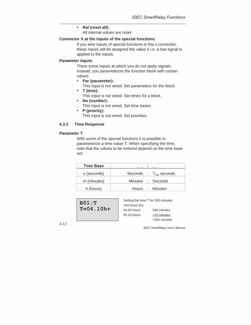
4.3.2 Time Response
Parameter TWith some of the special functions it is possible toparameterize a time value T. When specifying the time,note that the values to be entered depend on the time baseset:
Time Base _ _ : _ _
s (seconds) Seconds : 1/100 seconds
m (minutes) Minutes : Seconds
h (hours) Hours : Minutes
B01:TT=04.10h+
Setting the time T for 250 minutes:
Unit hours (h):
04.00 hours 240 minutes
00.10 hours +10 minutes
=250 minutes
IDEC SmartRelay Functions
4-13IDEC SmartRelay User’s Manual
Note Always specify a time T > 0.10 s. For T = 0.05 s and
T = 0.00 s the time T is not defined.
Accuracy of TAll electronic components have clock/minute differences.This can result in deviations in the set time (T). In IDECSmartRelay the maximum deviation is 1 %.Example:In 1 hour (3600 seconds) the deviation is 1 % (i.e.36 seconds).In 1 minute the deviation is therefore only 0.6 seconds.
Accuracy of the time switchTo ensure that this deviation doesn’t result in the clockrunning inaccurately in C variants, the time switch isregularly compared with a high–precision time base andadjusted accordingly.This results in a maximum time error of ±5s a day.
4.3.3 Clock Buffering
The internal clock of a IDEC SmartRelay module has apower buffer and continues to run if there is a power failure.The ambient temperature affects the duration of thereserve power. At an ambient temperature of 25°C thetypical power buffer is 80 hours.
4.3.4 Retentivity
The switching states and counter values can be keptretentively in the special functions. To do this, retentivitymust be switched on for the relevant function.
IDEC SmartRelay Functions
4-14IDEC SmartRelay User’s Manual
4.3.5 Degree of Protection
The parameter protection setting allows you to specifywhether the parameters can be displayed and altered inparameter assignment mode on the IDEC SmartRelaymodule.
There are two possible settings:
+: The parameter settings are also displayed in parameterassignment mode and can be changed.-: The parameter settings are not displayed in parameterassignment mode and can only be changed inprogramming mode.
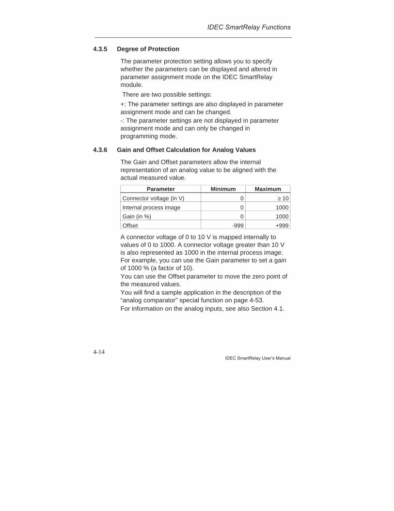
4.3.6 Gain and Offset Calculation for Analog Values
The Gain and Offset parameters allow the internalrepresentation of an analog value to be aligned with theactual measured value.
Parameter Minimum Maximum
Connector voltage (in V) 0 ≥ 10
Internal process image 0 1000
Gain (in %) 0 1000
Offset -999 +999
A connector voltage of 0 to 10 V is mapped internally tovalues of 0 to 1000. A connector voltage greater than 10 Vis also represented as 1000 in the internal process image.For example, you can use the Gain parameter to set a gainof 1000 % (a factor of 10).You can use the Offset parameter to move the zero point ofthe measured values.You will find a sample application in the description of the“analog comparator” special function on page 4-53.For information on the analog inputs, see also Section 4.1.
IDEC SmartRelay Functions
4-15IDEC SmartRelay User’s Manual
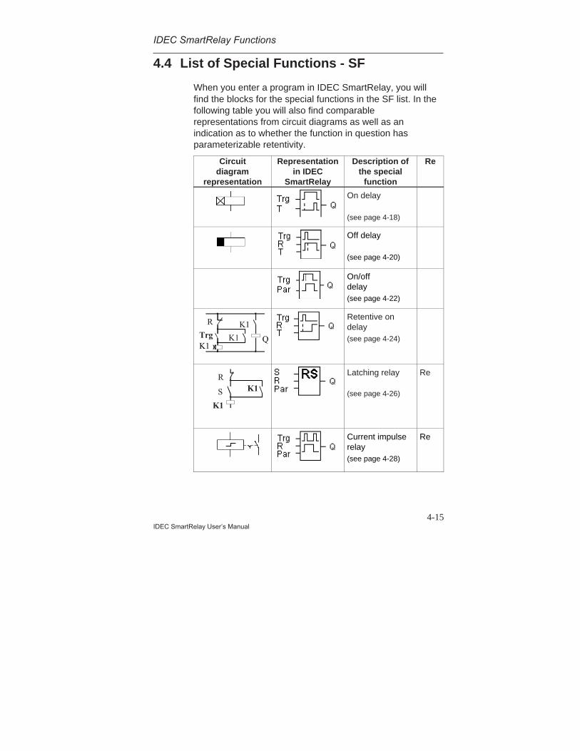
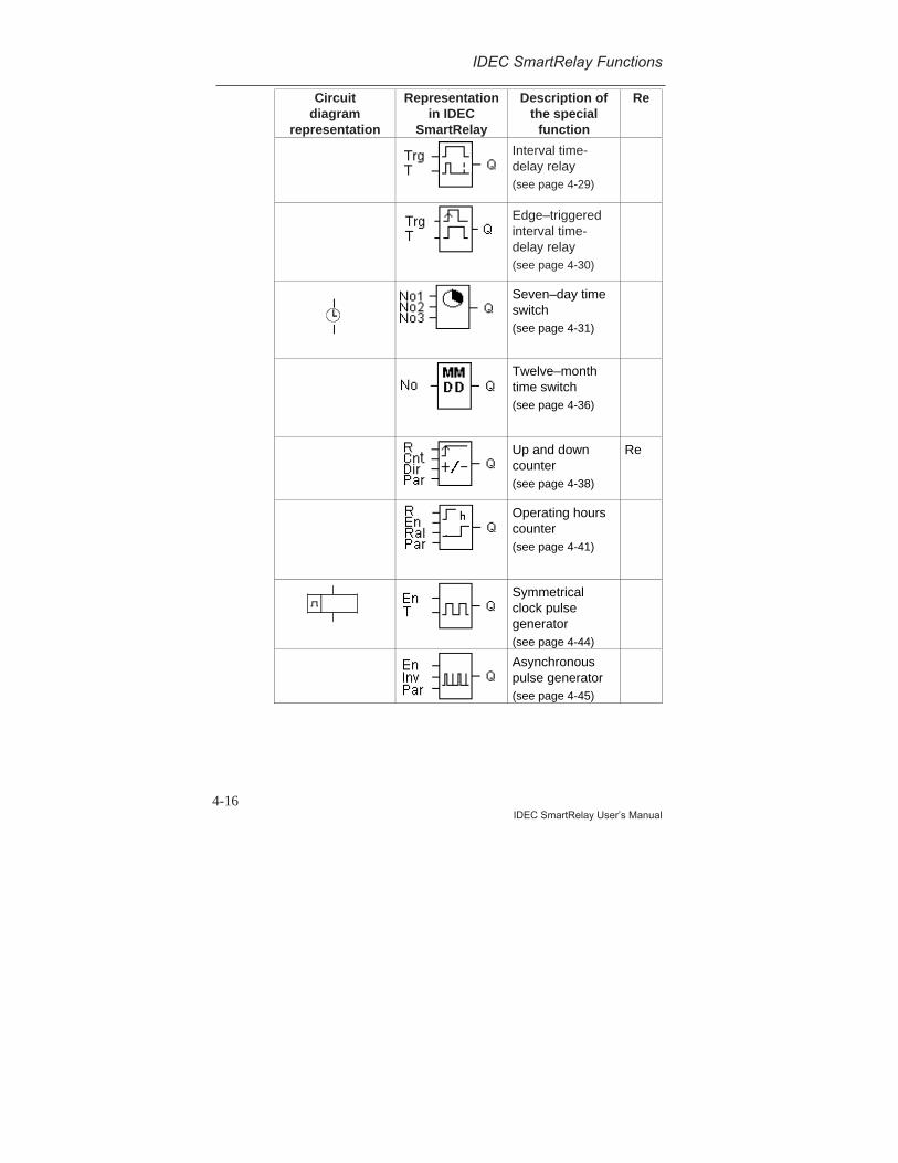
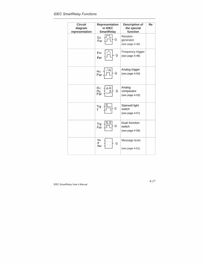
4.4 List of Special Functions - SF
When you enter a program in IDEC SmartRelay, you willfind the blocks for the special functions in the SF list. In thefollowing table you will also find comparablerepresentations from circuit diagrams as well as anindication as to whether the function in question hasparameterizable retentivity.
Circuitdiagram
representation
Representationin IDEC
SmartRelay
Description ofthe special
function
Re
On delay
(see page 4-18)
Off delay
(see page 4-20)
On/offdelay(see page 4-22)
R K1
K1QTrg K1
Retentive ondelay(see page 4-24)
R
S
K1
K1
Latching relay
(see page 4-26)
Re
Current impulserelay(see page 4-28)
Re
IDEC SmartRelay Functions
4-16IDEC SmartRelay User’s Manual
Circuitdiagram
representation
Representationin IDEC
SmartRelay
Description ofthe special
function
Re
Interval time-delay relay(see page 4-29)
Edge–triggeredinterval time-delay relay(see page 4-30)
Seven–day timeswitch(see page 4-31)
Twelve–monthtime switch(see page 4-36)
Up and downcounter(see page 4-38)
Re
Operating hourscounter(see page 4-41)
Symmetricalclock pulsegenerator(see page 4-44)
Asynchronouspulse generator(see page 4-45)
IDEC SmartRelay Functions
4-17IDEC SmartRelay User’s Manual
Circuitdiagram
representation
Representationin IDEC
SmartRelay
Description ofthe special
function
Re
Randomgenerator(see page 4-46)
Fre
Par
Frequency trigger(see page 4-48)
Analog trigger(see page 4-50)
Analogcomparator(see page 4-53)
Stairwell lightswitch(see page 4-57)
Dual–functionswitch(see page 4-59)
EnPPar
Message texts
(see page 4-61)

IDEC SmartRelay Functions
4-18IDEC SmartRelay User’s Manual
4.4.1 On Delay
Brief descriptionIf the on delay is selected, the output is not switched overuntil a definable time period has elapsed.
Symbol inIDEC
SmartRelay:
Connection Description
Input Trg Use Trg (trigger) input tostart the time for the ondelay.
Parameter T T is the time after which theoutput is switched on (outputsignal is switched from 0 to1).
Output Q Q switches on afterexpiration of the defined timeT if Trg is still set.
Parameter TPlease note the parameter values for the T parameter inSection 4.3.2.
Timing diagram
Trg
T T
T a starts
Q
The bold part of thetiming diagram ap -pears in the on-delaysymbol.
Description of functionWhen the state at the Trg input changes from 0 to 1, thetime Ta begins to elapse (Ta is the current time in IDECSmartRelay).

IDEC SmartRelay Functions
4-19IDEC SmartRelay User’s Manual
If the state at the Trg input remains 1 at least for theduration of the parameterized time T, the output is set to 1after the time T has elapsed (there is a delay between theinput being switched on and the output coming on).If the state at the Trg input switches back to 0 before thetime T has elapsed, the time is reset.The output is reset to 0 if the state at the Trg input is 0.In the event of a power failure, the elapsed time is reset.
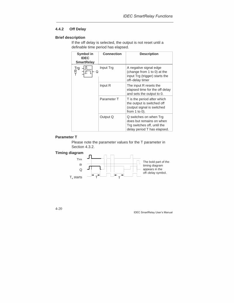
IDEC SmartRelay Functions
4-20IDEC SmartRelay User’s Manual
4.4.2 Off Delay
Brief descriptionIf the off delay is selected, the output is not reset until adefinable time period has elapsed.
Symbol inIDEC
SmartRelay
Connection Description
Input Trg A negative signal edge(change from 1 to 0) at theinput Trg (trigger) starts theoff–delay timer
Input R The input R resets theelapsed time for the off delayand sets the output to 0.
Parameter T T is the period after whichthe output is switched off(output signal is switchedfrom 1 to 0).
Output Q Q switches on when Trgdoes but remains on whenTrg switches off, until thedelay period T has elapsed.
Parameter TPlease note the parameter values for the T parameter inSection 4.3.2.
Timing diagram
Trg
TTTa starts
QR
The bold part of thetiming diagramappears in theoff–delay symbol.
IDEC SmartRelay Functions
4-21IDEC SmartRelay User’s Manual
Description of functionWhen the state at the input Trg changes to 1, the output Qswitches to 1 immediately.If the state at the input Trg changes from 1 to 0, the currenttime Ta starts in IDEC SmartRelay, and the output remainsset. If Ta reaches the values specified via T (Ta=T), theoutput Q is reset to 0 (off delay).If the Trg input switches on and off again, the time Ta startsagain.The input R (Reset) resets the elapsed time Ta and theoutput before the set time delay Ta has elapsed.In the event of a power failure, the elapsed time is reset.
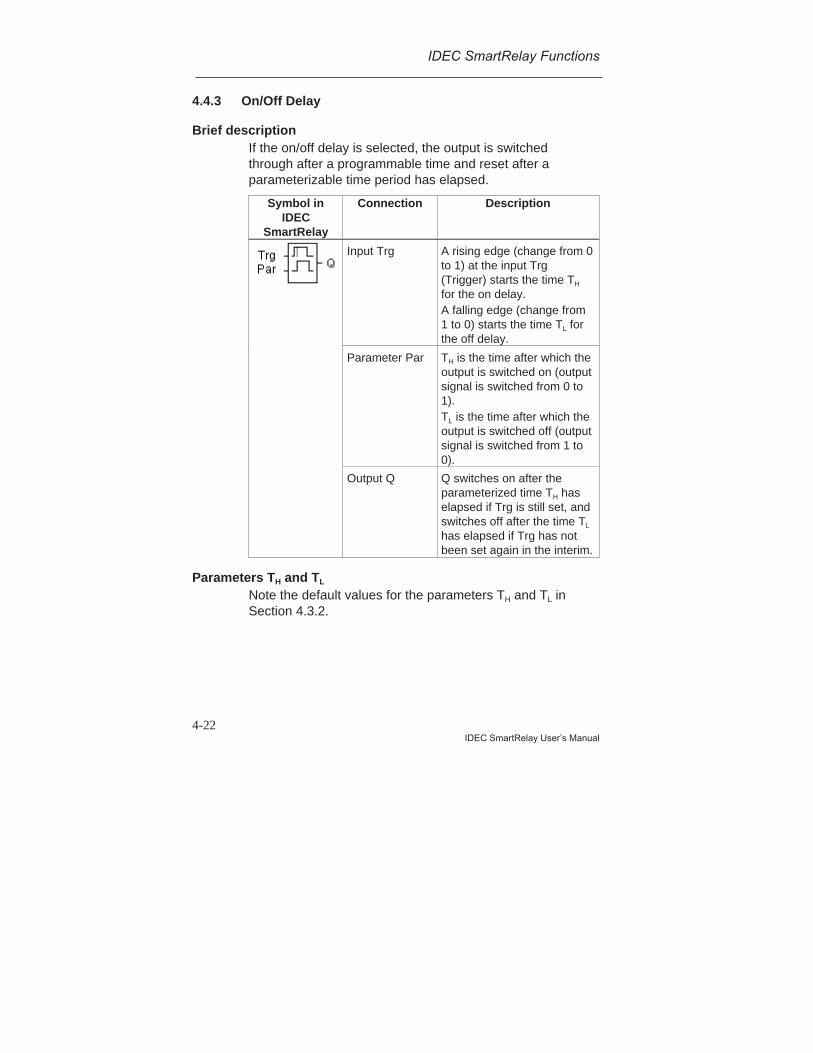
IDEC SmartRelay Functions
4-22IDEC SmartRelay User’s Manual
4.4.3 On/Off Delay
Brief descriptionIf the on/off delay is selected, the output is switchedthrough after a programmable time and reset after aparameterizable time period has elapsed.
Symbol inIDEC
SmartRelay
Connection Description
Input Trg A rising edge (change from 0to 1) at the input Trg(Trigger) starts the time TH
for the on delay.A falling edge (change from1 to 0) starts the time TL forthe off delay.
Parameter Par TH is the time after which theoutput is switched on (outputsignal is switched from 0 to1).TL is the time after which theoutput is switched off (outputsignal is switched from 1 to0).
Output Q Q switches on after theparameterized time TH haselapsed if Trg is still set, andswitches off after the time TL
has elapsed if Trg has notbeen set again in the interim.
Parameters TH and TL
Note the default values for the parameters TH and TL inSection 4.3.2.
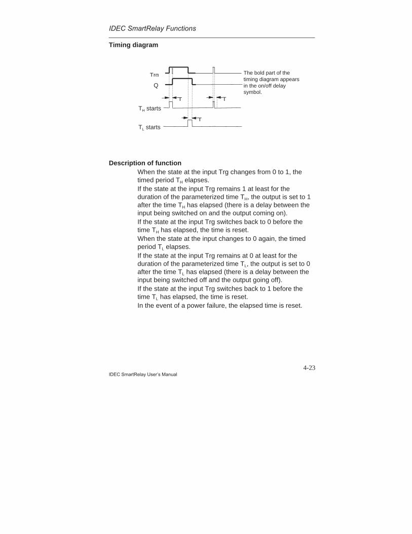
IDEC SmartRelay Functions
4-23IDEC SmartRelay User’s Manual
Timing diagram
Description of functionWhen the state at the input Trg changes from 0 to 1, thetimed period TH elapses.If the state at the input Trg remains 1 at least for theduration of the parameterized time TH, the output is set to 1after the time TH has elapsed (there is a delay between theinput being switched on and the output coming on).If the state at the input Trg switches back to 0 before thetime TH has elapsed, the time is reset.When the state at the input changes to 0 again, the timedperiod TL elapses.If the state at the input Trg remains at 0 at least for theduration of the parameterized time TL, the output is set to 0after the time TL has elapsed (there is a delay between theinput being switched off and the output going off).If the state at the input Trg switches back to 1 before thetime TL has elapsed, the time is reset.In the event of a power failure, the elapsed time is reset.
Trg
T T
TH starts
Q
TTL starts
The bold part of thetiming diagram appearsin the on/off delaysymbol.
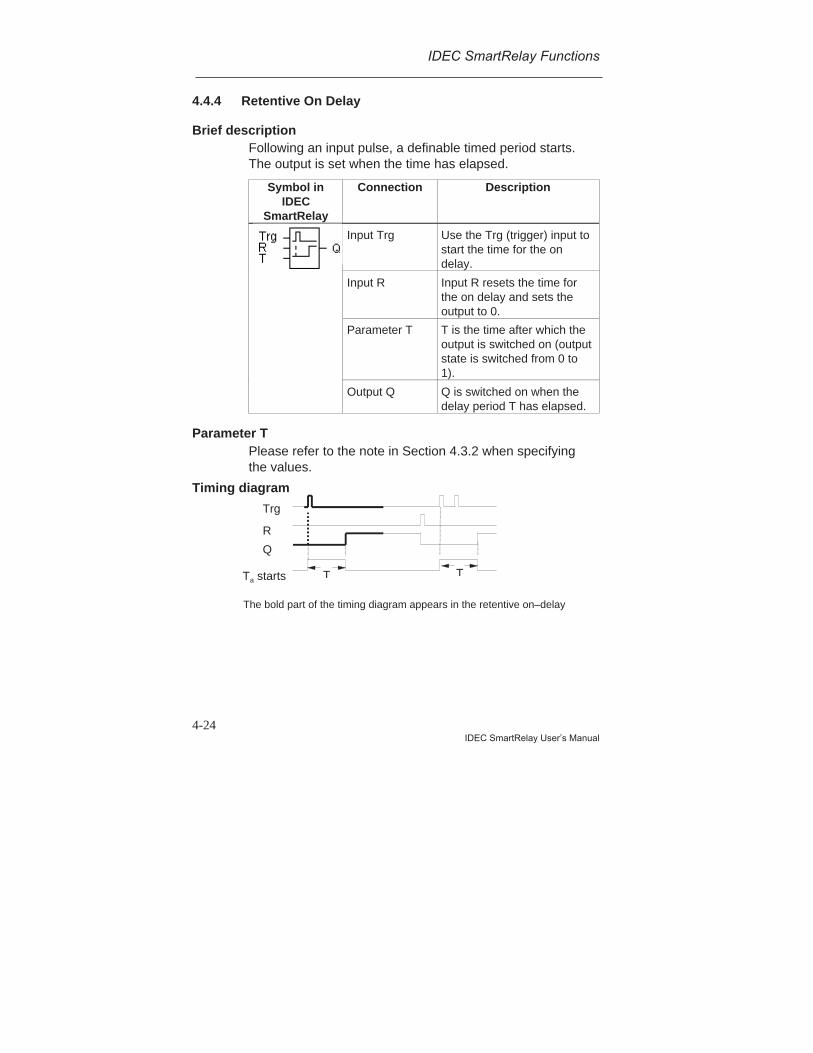
IDEC SmartRelay Functions
4-24IDEC SmartRelay User’s Manual
4.4.4 Retentive On Delay
Brief descriptionFollowing an input pulse, a definable timed period starts.The output is set when the time has elapsed.
Symbol inIDEC
SmartRelay
Connection Description
Input Trg Use the Trg (trigger) input tostart the time for the ondelay.
Input R Input R resets the time forthe on delay and sets theoutput to 0.
Parameter T T is the time after which theoutput is switched on (outputstate is switched from 0 to1).
Output Q Q is switched on when thedelay period T has elapsed.
Parameter TPlease refer to the note in Section 4.3.2 when specifyingthe values.
Timing diagram
Trg
TTa starts
Q
R
T
The bold part of the timing diagram appears in the retentive on–delay
IDEC SmartRelay Functions
4-25IDEC SmartRelay User’s Manual
Description of functionWhen the state at the Trg input changes from 0 to 1, thecurrent time Ta starts. When Ta reaches the time T, output Qis set to 1. Another switching operation at the Trg input hasno effect on Ta.The output and the time Ta are not reset to 0, until the stateof the R input changes to 1 again.In the event of a power failure, the elapsed time is reset.
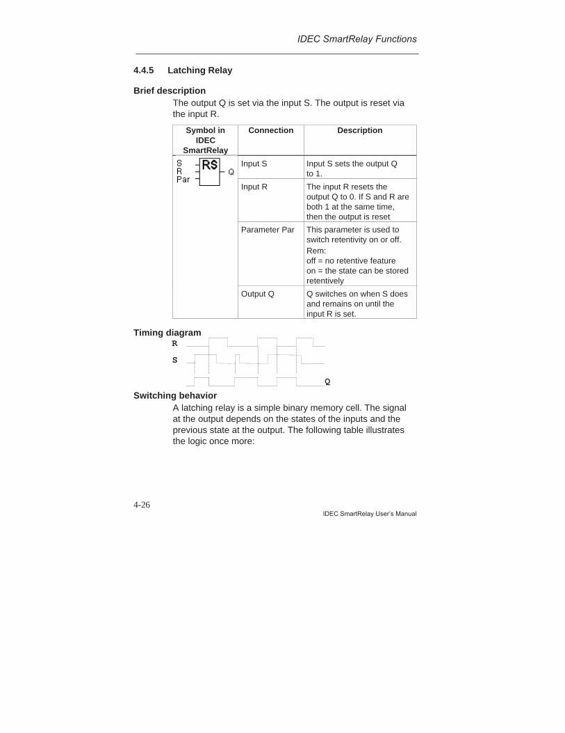
IDEC SmartRelay Functions
4-26IDEC SmartRelay User’s Manual
4.4.5 Latching Relay
Brief descriptionThe output Q is set via the input S. The output is reset viathe input R.
Symbol inIDEC
SmartRelay
Connection Description
Input S Input S sets the output Qto 1.
Input R The input R resets theoutput Q to 0. If S and R areboth 1 at the same time,then the output is reset
Parameter Par This parameter is used toswitch retentivity on or off.Rem:off = no retentive featureon = the state can be storedretentively
Output Q Q switches on when S doesand remains on until theinput R is set.
Timing diagram
Switching behaviorA latching relay is a simple binary memory cell. The signalat the output depends on the states of the inputs and theprevious state at the output. The following table illustratesthe logic once more:
S
R
Q
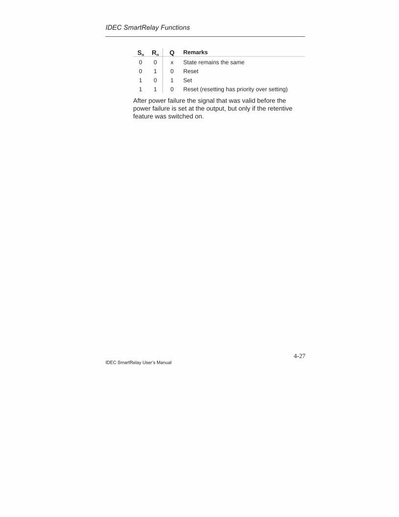
IDEC SmartRelay Functions
4-27IDEC SmartRelay User’s Manual
Sn Rn Q Remarks
0 0 x State remains the same
0 1 0 Reset
1 0 1 Set
1 1 0 Reset (resetting has priority over setting)
After power failure the signal that was valid before thepower failure is set at the output, but only if the retentivefeature was switched on.
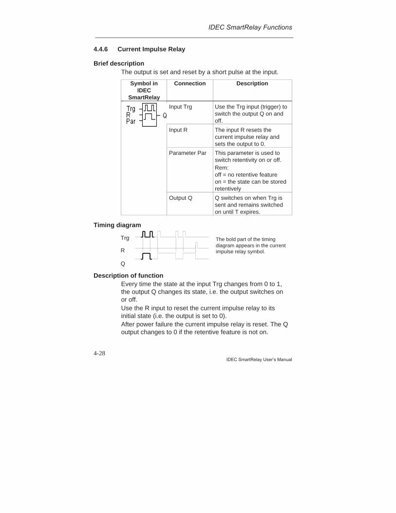
IDEC SmartRelay Functions
4-28IDEC SmartRelay User’s Manual
4.4.6 Current Impulse Relay
Brief descriptionThe output is set and reset by a short pulse at the input.
Symbol inIDEC
SmartRelay
Connection Description
Input Trg Use the Trg input (trigger) toswitch the output Q on andoff.
Input R The input R resets thecurrent impulse relay andsets the output to 0.
Parameter Par This parameter is used toswitch retentivity on or off.Rem:off = no retentive featureon = the state can be storedretentively
Output Q Q switches on when Trg issent and remains switchedon until T expires.
Timing diagram
Description of functionEvery time the state at the input Trg changes from 0 to 1,the output Q changes its state, i.e. the output switches onor off.Use the R input to reset the current impulse relay to itsinitial state (i.e. the output is set to 0).After power failure the current impulse relay is reset. The Qoutput changes to 0 if the retentive feature is not on.
Trg
Q
R
The bold part of the timingdiagram appears in the currentimpulse relay symbol.

IDEC SmartRelay Functions
4-29IDEC SmartRelay User’s Manual
4.4.7 Interval Time–Delay Relay - Pulse Output
Brief descriptionAn input signal produces a signal of definable duration atthe output.
Symbol inIDEC
SmartRelay
Connection Description
Input Trg The input Trg (trigger) startsthe time for the intervaltime–delay relay.
Parameter T T is the period after whichthe output is switched off(output signal is switchedfrom 1 to 0).
Output Q Q comes on with Trg andremains on during the timeTa and while the input is setto 1.
Parameter TPlease refer to the note on the T parameter inSection 4.3.2.
Timing diagram
Description of functionWhen the input Trg switches to the state 1, the output Qimmediately switches to the state 1. At the same time, theelapsed time Ta starts running; the output remains set.If Ta reaches the value specified by means of T (Ta=T), theoutput Q is reset to 0 (pulse output).If the state at the input Trg switches back from 1 to 0 beforethe specified time has elapsed, the output also immediatelyswitches back from 1 to 0.
Trg
Ta starts
Q
The bold part of the timing diagramappears in the interval time–delayrelay symbol.
T has not expired completely
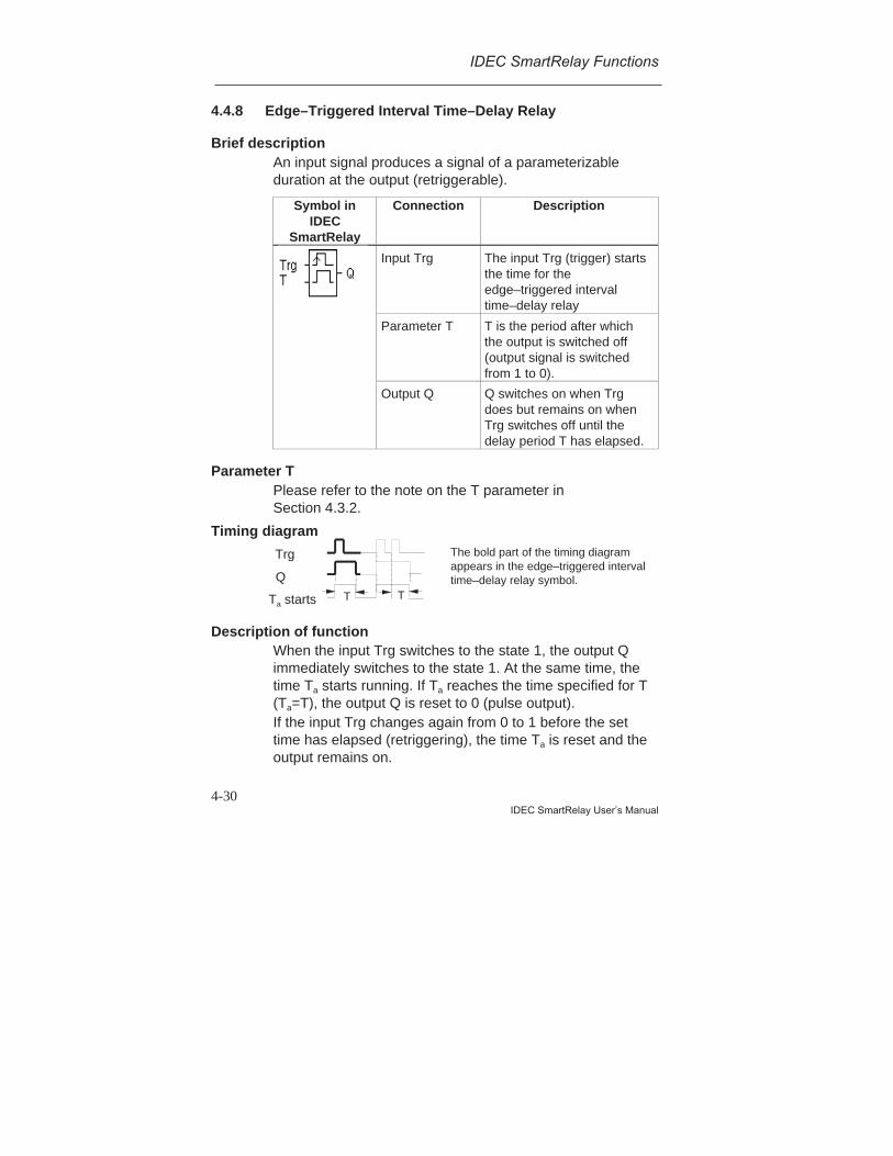
IDEC SmartRelay Functions
4-30IDEC SmartRelay User’s Manual
4.4.8 Edge–Triggered Interval Time–Delay Relay
Brief descriptionAn input signal produces a signal of a parameterizableduration at the output (retriggerable).
Symbol inIDEC
SmartRelay
Connection Description
Input Trg The input Trg (trigger) startsthe time for theedge–triggered intervaltime–delay relay
Parameter T T is the period after whichthe output is switched off(output signal is switchedfrom 1 to 0).
Output Q Q switches on when Trgdoes but remains on whenTrg switches off until thedelay period T has elapsed.
Parameter TPlease refer to the note on the T parameter inSection 4.3.2.
Timing diagram
Description of functionWhen the input Trg switches to the state 1, the output Qimmediately switches to the state 1. At the same time, thetime Ta starts running. If Ta reaches the time specified for T(Ta=T), the output Q is reset to 0 (pulse output).If the input Trg changes again from 0 to 1 before the settime has elapsed (retriggering), the time Ta is reset and theoutput remains on.
The bold part of the timing diagramappears in the edge–triggered intervaltime–delay relay symbol.
Trg
Ta starts
Q
T T
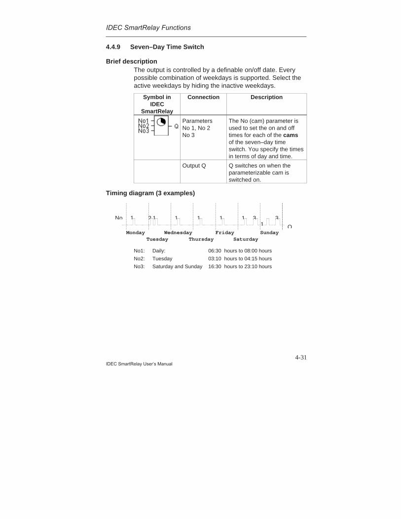
IDEC SmartRelay Functions
4-31IDEC SmartRelay User’s Manual
4.4.9 Seven–Day Time Switch
Brief descriptionThe output is controlled by a definable on/off date. Everypossible combination of weekdays is supported. Select theactive weekdays by hiding the inactive weekdays.
Symbol inIDEC
SmartRelay
Connection Description
ParametersNo 1, No 2No 3
The No (cam) parameter isused to set the on and offtimes for each of the camsof the seven–day timeswitch. You specify the timesin terms of day and time.
Output Q Q switches on when theparameterizable cam isswitched on.
Timing diagram (3 examples)
No1: Daily: 06:30 hours to 08:00 hours
No2: Tuesday 03:10 hours to 04:15 hours
No3: Saturday and Sunday 16:30 hours to 23:10 hours
Monday WednesdayTuesday Saturday
FridayThursday
SundayQ
1No 1 31 2 31 11
1
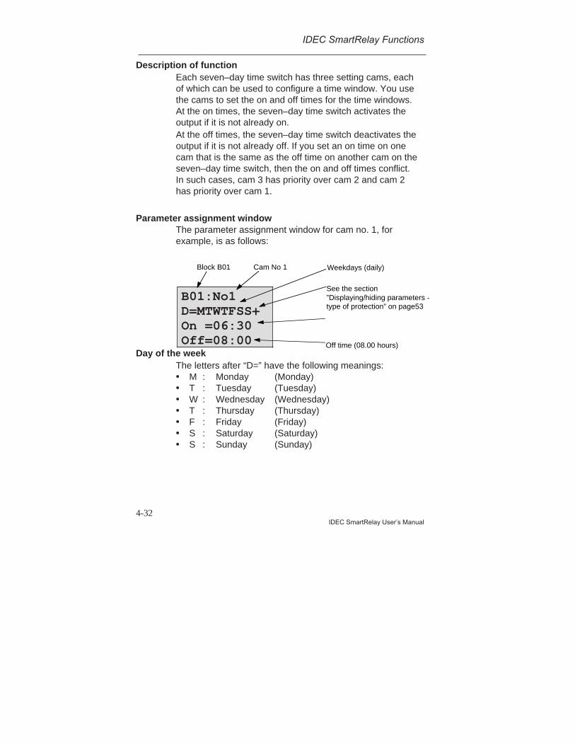
IDEC SmartRelay Functions
4-32IDEC SmartRelay User’s Manual
Description of functionEach seven–day time switch has three setting cams, eachof which can be used to configure a time window. You usethe cams to set the on and off times for the time windows.At the on times, the seven–day time switch activates theoutput if it is not already on.At the off times, the seven–day time switch deactivates theoutput if it is not already off. If you set an on time on onecam that is the same as the off time on another cam on theseven–day time switch, then the on and off times conflict.In such cases, cam 3 has priority over cam 2 and cam 2has priority over cam 1.
Parameter assignment windowThe parameter assignment window for cam no. 1, forexample, is as follows:
Day of the weekThe letters after “D=” have the following meanings:• M : Monday (Monday)• T : Tuesday (Tuesday)• W : Wednesday (Wednesday)• T : Thursday (Thursday)• F : Friday (Friday)• S : Saturday (Saturday)• S : Sunday (Sunday)
B01:No1D=MTWTFSS+On =06:30Off=08:00
See the section”Displaying/hiding parameters -type of protection” on page53
Off time (08.00 hours)
Block B01 Cam No 1 Weekdays (daily)
IDEC SmartRelay Functions
4-33IDEC SmartRelay User’s Manual
An uppercase letter means the weekday has beenselected. A ”-” means the weekday has not been selected.
Switching timesYou can set any time between 00:00 and 23:59.- -:- - means no switching on or off.
Setting the seven–day time switchTo enter the switching times, proceed as follows:
1. Position the cursor on one of the time switch’s cam (No)parameters (e.g. No1).
2. Press OK. IDEC SmartRelay opens the parameterassignment window for the cam. The cursor ispositioned on the day of the week.
3. Use the and keys to select one or more days of theweek.
4. Use the key to move the cursor to the first position forthe on time.
5. Set the on time.Use the and keys to change the value. To move thecursor from one position to another, use the and keys. You can only select the value - -:- - at the first digit(- -:- - means no switching operation).
6. Use the key to move the cursor to the first position forthe off time.
7. Set the off time (same procedure as for step 5).8. Conclude your input by pressing OK.
The cursor is positioned at parameter No 2 (cam 2).You can now parameterize another cam.
Note Please refer to the technical specifications in Section 4.3.2
for information regarding the accuracy of the time switch.
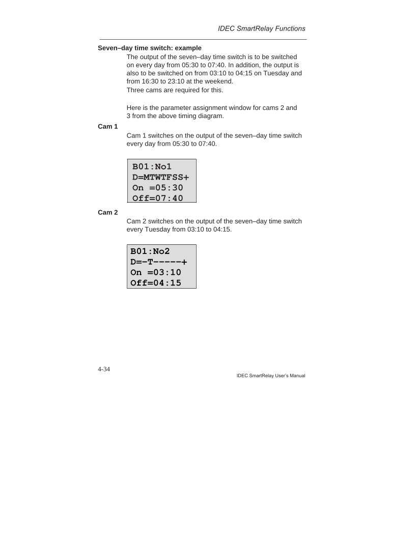
IDEC SmartRelay Functions
4-34IDEC SmartRelay User’s Manual
Seven–day time switch: exampleThe output of the seven–day time switch is to be switchedon every day from 05:30 to 07:40. In addition, the output isalso to be switched on from 03:10 to 04:15 on Tuesday andfrom 16:30 to 23:10 at the weekend.Three cams are required for this.
Here is the parameter assignment window for cams 2 and3 from the above timing diagram.
Cam 1Cam 1 switches on the output of the seven–day time switchevery day from 05:30 to 07:40.
Cam 2Cam 2 switches on the output of the seven–day time switchevery Tuesday from 03:10 to 04:15.
B01:No1D=MTWTFSS+On =05:30Off=07:40
B01:No2D=-T-----+On =03:10Off=04:15

IDEC SmartRelay Functions
4-35IDEC SmartRelay User’s Manual
Cam 3Cam 3 switches on the output of the seven–day time switchevery Saturday and Sunday from 16:30 to 23:10.
Result
No
Monday WednesdayTuesday Saturday
FridayThursday
Sunday
1 31 2 3
Q
1 1 11
B01:No3D=-----SS+On =16:30Off=23:10
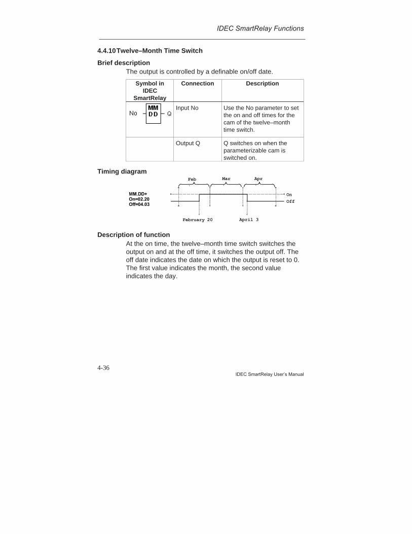
IDEC SmartRelay Functions
4-36IDEC SmartRelay User’s Manual
4.4.10Twelve–Month Time Switch
Brief descriptionThe output is controlled by a definable on/off date.
Symbol inIDEC
SmartRelay
Connection Description
Input No Use the No parameter to setthe on and off times for thecam of the twelve–monthtime switch.
Output Q Q switches on when theparameterizable cam isswitched on.
Timing diagram
MM.DD+On=02.20Off=04.03
OnOff
February 20 April 3
Feb.
Mar.
Apr.
Description of functionAt the on time, the twelve–month time switch switches theoutput on and at the off time, it switches the output off. Theoff date indicates the date on which the output is reset to 0.The first value indicates the month, the second valueindicates the day.

IDEC SmartRelay Functions
4-37IDEC SmartRelay User’s Manual
Parameterization exampleThe output of a IDEC SmartRelay has to be switched onevery year on March 1 and switched off on April 4,switched on again on July 7 and switched off on November19. For this you require 2 twelve–month time switches eachof which is configured for one of the on periods. Theoutputs are then linked by an OR block.
B01:No MM.DDOn=03.01Off=04.04
B02:No MM.DDOn=07.07Off=11.19
1 March
4 April
7 July
19 November
B01 B02On
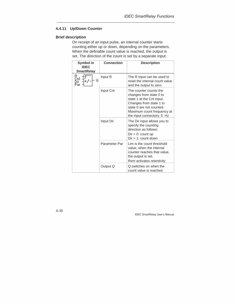
IDEC SmartRelay Functions
4-38IDEC SmartRelay User’s Manual
4.4.11 Up/Down Counter
Brief descriptionOn receipt of an input pulse, an internal counter startscounting either up or down, depending on the parameters.When the definable count value is reached, the output isset. The direction of the count is set by a separate input.
Symbol inIDEC
SmartRelay
Connection Description
Input R The R input can be used toreset the internal count valueand the output to zero.
Input Cnt The counter counts thechanges from state 0 tostate 1 at the Cnt input.Changes from state 1 tostate 0 are not counted.Maximum count frequency atthe input connectors: 5 Hz
Input Dir The Dir input allows you tospecify the countingdirection as follows:Dir = 0: count upDir = 1: count down
Parameter Par Lim is the count thresholdvalue; when the internalcounter reaches that value,the output is set.Rem activates retentivity
Output Q Q switches on when thecount value is reached.

IDEC SmartRelay Functions
4-39IDEC SmartRelay User’s Manual
Timing diagram
R
Dir
Par
Cnt
0
Q
Internalcount valueCnt
Description of functionAt each positive signal edge at the input, Cnt eitherincreases the internal counter value by one (Dir = 0) ordecreases it by one (Dir = 1).If the internal counter value is greater than or equal to thevalue specified for Par, the output Q is set to 1.The Reset input R can be used to reset the internal countervalue and the output to ’000000’. As long as R=1, theoutput remains set to 0 and the pulses at the input Cnt arenot counted.
Par parameter setting
If the internal counter value is greater than or equal to Par,output Q is set. The counter remains the same in the caseof under or overflow.Lim can be anything between 0 and 999999.Rem: This parameter switches the retentive feature of theinternal Cnt counter on and off.off = No retentive featureon = The Cnt counter can be stored retentively
B03:Par
Rem=off
Lim= 000100+
Count value
Retentivity
See the section ”Displaying/hidingparameters - type of protection” onpage53

IDEC SmartRelay Functions
4-40IDEC SmartRelay User’s Manual
If the retentive feature is switched on, when a power failureoccurs the counter status remains the same and this valueis used once power is restored.
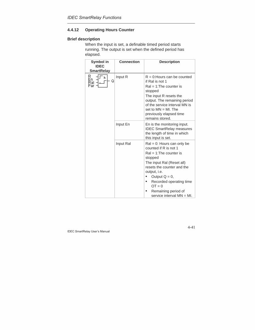
IDEC SmartRelay Functions
4-41IDEC SmartRelay User’s Manual
4.4.12 Operating Hours Counter
Brief descriptionWhen the input is set, a definable timed period startsrunning. The output is set when the defined period haselapsed.
Symbol inIDEC
SmartRelay
Connection Description
Input R R = 0:Hours can be countedif Ral is not 1Ral = 1:The counter isstoppedThe input R resets theoutput. The remaining periodof the service interval MN isset to MN = MI. Thepreviously elapsed timeremains stored.
Input En En is the monitoring input.IDEC SmartRelay measuresthe length of time in whichthis input is set.
Input Ral Ral = 0: Hours can only becounted if R is not 1Ral = 1:The counter isstoppedThe input Ral (Reset all)resets the counter and theoutput, i.e.• Output Q = 0,• Recorded operating time
OT = 0• Remaining period of
service interval MN = MI.
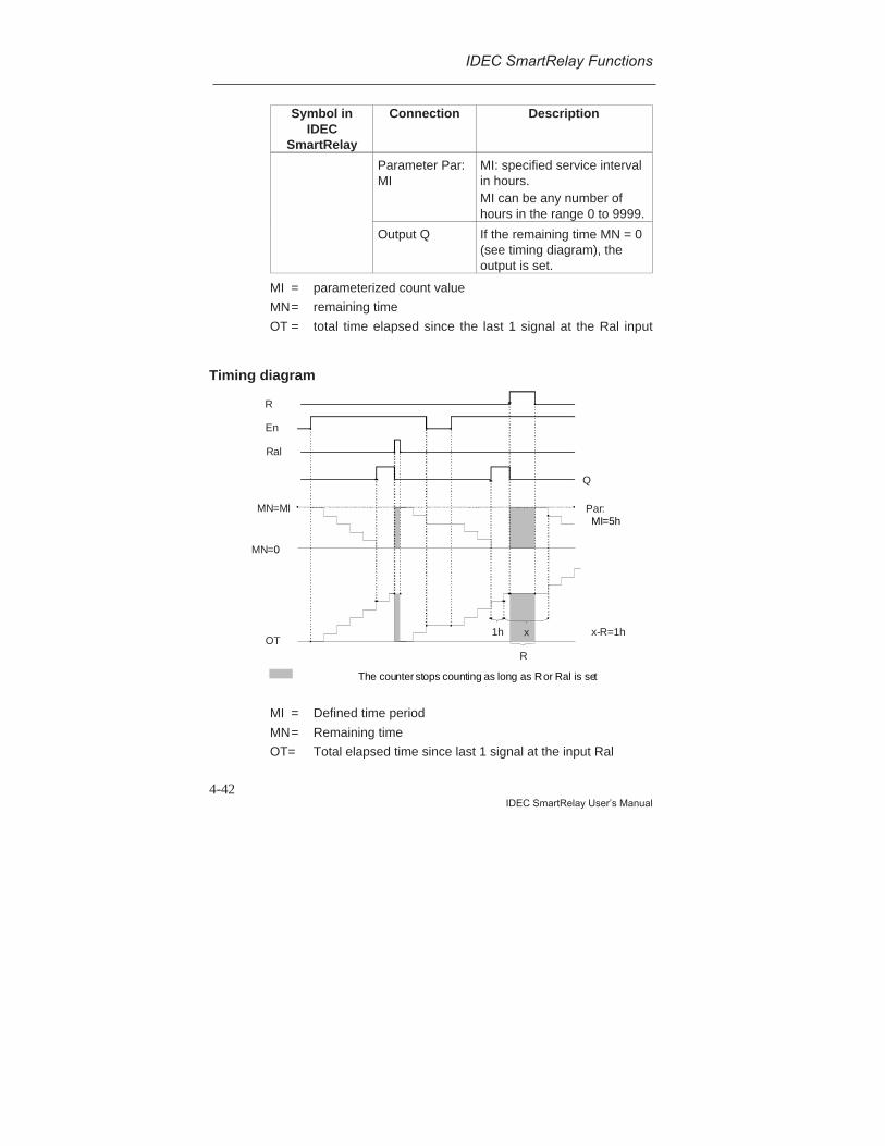
IDEC SmartRelay Functions
4-42IDEC SmartRelay User’s Manual
Symbol inIDEC
SmartRelay
Connection Description
Parameter Par:MI
MI: specified service intervalin hours.MI can be any number ofhours in the range 0 to 9999.
Output Q If the remaining time MN = 0(see timing diagram), theoutput is set.
MI = parameterized count value
MN= remaining time
OT = total time elapsed since the last 1 signal at the Ral input
Timing diagram
1h x-R=1h
R
x
Par:
Q
R
Ral
En
MN=MI
OT
MN=0
The counter stops counting as long as R or Ral is set
MI=5h
MI = Defined time period
MN= Remaining time
OT= Total elapsed time since last 1 signal at the input Ral
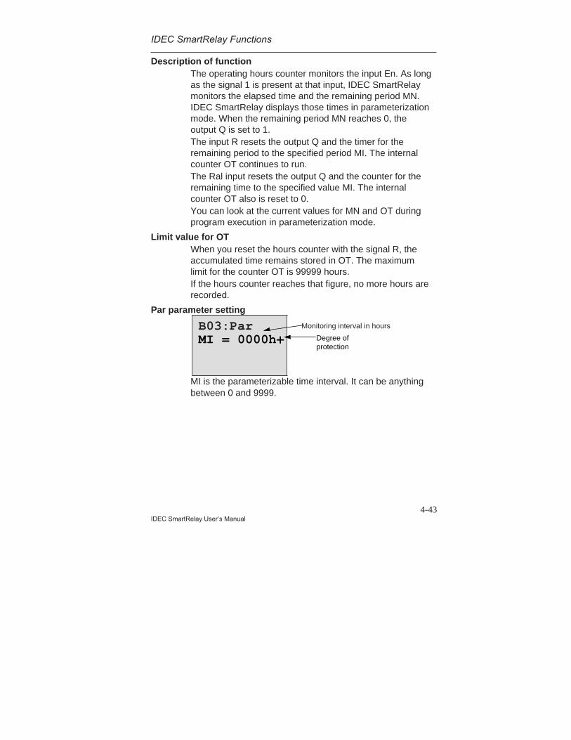
IDEC SmartRelay Functions
4-43IDEC SmartRelay User’s Manual
Description of functionThe operating hours counter monitors the input En. As longas the signal 1 is present at that input, IDEC SmartRelaymonitors the elapsed time and the remaining period MN.IDEC SmartRelay displays those times in parameterizationmode. When the remaining period MN reaches 0, theoutput Q is set to 1.The input R resets the output Q and the timer for theremaining period to the specified period MI. The internalcounter OT continues to run.The Ral input resets the output Q and the counter for theremaining time to the specified value MI. The internalcounter OT also is reset to 0.You can look at the current values for MN and OT duringprogram execution in parameterization mode.
Limit value for OTWhen you reset the hours counter with the signal R, theaccumulated time remains stored in OT. The maximumlimit for the counter OT is 99999 hours.If the hours counter reaches that figure, no more hours arerecorded.
Par parameter setting
MI is the parameterizable time interval. It can be anythingbetween 0 and 9999.
B03:ParMI = 0000h+
Monitoring interval in hours
Degree ofprotection
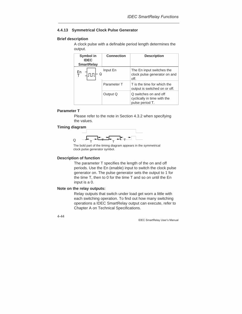
IDEC SmartRelay Functions
4-44IDEC SmartRelay User’s Manual
4.4.13 Symmetrical Clock Pulse Generator
Brief descriptionA clock pulse with a definable period length determines theoutput.
Symbol inIDEC
SmartRelay
Connection Description
Input En The En input switches theclock pulse generator on andoff.
Parameter T T is the time for which theoutput is switched on or off.
Output Q Q switches on and offcyclically in time with thepulse period T.
Parameter TPlease refer to the note in Section 4.3.2 when specifyingthe values.
Timing diagram
Description of functionThe parameter T specifies the length of the on and offperiods. Use the En (enable) input to switch the clock pulsegenerator on. The pulse generator sets the output to 1 forthe time T, then to 0 for the time T and so on until the Eninput is a 0.
Note on the relay outputs:Relay outputs that switch under load get worn a little witheach switching operation. To find out how many switchingoperations a IDEC SmartRelay output can execute, refer toChapter A on Technical Specifications.
Q T TT T
The bold part of the timing diagram appears in the symmetricalclock pulse generator symbol.

IDEC SmartRelay Functions
4-45IDEC SmartRelay User’s Manual
4.4.14 Asynchronous Pulse Generator
Brief descriptionThe pulse form of the output can be modified by means ofthe definable pulse duration/interpulse period ratio.
Symbol inIDEC
SmartRelay
Connection Description
Input En The En input switches theasynchronous pulsegenerator on and off.
INV input The input INV inverts theoutput signal of theasynchronous clock pulsegenerator when active.
Parameter Par You can set the pulseduration TH and theinterpulse period TL.
Output Q Q switches on and offcyclically with the times TH
and TL.
Timing diagram
Description of functionYou can set the pulse duration and interpulse period usingthe parameters TH (Time High) and TL (Time Low). Bothparameters have the same time base; they cannot be setindividually to different bases.The INV input allows the output to be inverted. The inputINV only negates the output if the block is activated by EN.
En
Inv
TH
Q
TL THTL TH TLTH
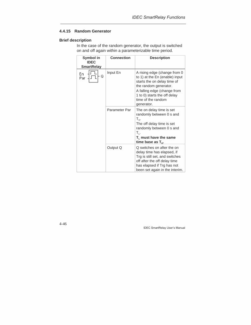
IDEC SmartRelay Functions
4-46IDEC SmartRelay User’s Manual
4.4.15 Random Generator
Brief descriptionIn the case of the random generator, the output is switchedon and off again within a parameterizable time period.
Symbol inIDEC
SmartRelay
Connection Description
Input En A rising edge (change from 0to 1) at the En (enable) inputstarts the on delay time ofthe random generator.A falling edge (change from1 to 0) starts the off delaytime of the randomgenerator.
Parameter Par The on delay time is setrandomly between 0 s andTH.The off delay time is setrandomly between 0 s andTL.TL must have the sametime base as TH.
Output Q Q switches on after the ondelay time has elapsed, ifTrg is still set, and switchesoff after the off delay timehas elapsed if Trg has notbeen set again in the interim.
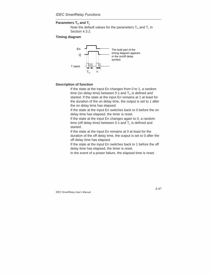
IDEC SmartRelay Functions
4-47IDEC SmartRelay User’s Manual
Parameters TH and TL
Note the default values for the parameters TH and TL inSection 4.3.2.
Timing diagram
Description of functionIf the state at the input En changes from 0 to 1, a randomtime (on delay time) between 0 s and TH is defined andstarted. If the state at the input En remains at 1 at least forthe duration of the on delay time, the output is set to 1 afterthe on delay time has elapsed.If the state at the input En switches back to 0 before the ondelay time has elapsed, the timer is reset.If the state at the input En changes again to 0, a randomtime (off delay time) between 0 s and TL is defined andstarted.If the state at the input En remains at 0 at least for theduration of the off delay time, the output is set to 0 after theoff delay time has elapsed.If the state at the input En switches back to 1 before the offdelay time has elapsed, the timer is reset.In the event of a power failure, the elapsed time is reset.
En
T starts
Q
TLTH
The bold part of thetiming diagram appearsin the on/off delaysymbol.
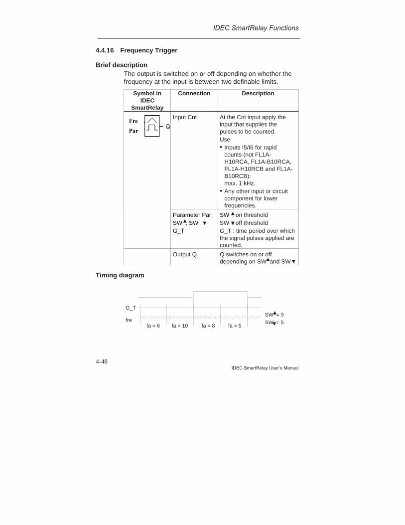
IDEC SmartRelay Functions
4-48IDEC SmartRelay User’s Manual
4.4.16 Frequency Trigger
Brief descriptionThe output is switched on or off depending on whether thefrequency at the input is between two definable limits.
Symbol inIDEC
SmartRelay
Connection Description
Fre
Par
Input Cnt At the Cnt input apply theinput that supplies thepulses to be counted.Use• Inputs I5/I6 for rapid
counts (not FL1A-H10RCA, FL1A-B10RCA,FL1A-H10RCB and FL1A-B10RCB):max. 1 kHz.
• Any other input or circuitcomponent for lowerfrequencies.
Parameter Par:SW , SWG_T
SW : on thresholdSW : off thresholdG_T : time period over whichthe signal pulses applied arecounted.
Output Q Q switches on or offdepending on SW and SW .
Timing diagram
fa = 6 fa = 10 fa = 8 fa = 5
G_T
fre SW = 5
SW = 9
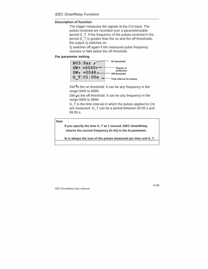
IDEC SmartRelay Functions
4-49IDEC SmartRelay User’s Manual
Description of functionThe trigger measures the signals at the Cnt input. Thepulses received are recorded over a parameterizableperiod G_T. If the frequency of the pulses received in theperiod G_T is greater than the on and the off thresholds,the output Q switches on.Q switches off again if the measured pulse frequencyreaches or falls below the off threshold.
Par parameter setting
B03:ParSW =0050+SW =0048G_T:01:00s
On threshold
Degree ofprotection
Time interval for pulses
Off threshold
SW is the on threshold. It can be any frequency in therange 0000 to 9999.SW is the off threshold. It can be any frequency in therange 0000 to 9999.G_T is the time interval in which the pulses applied to Cntare measured. G_T can be a period between 00.05 s and99.95 s.
Note
If you specify the time G_T as 1 second, IDEC SmartRelay
returns the current frequency (in Hz) in the fa parameter.
fa is always the sum of the pulses measured per time unit G_T.
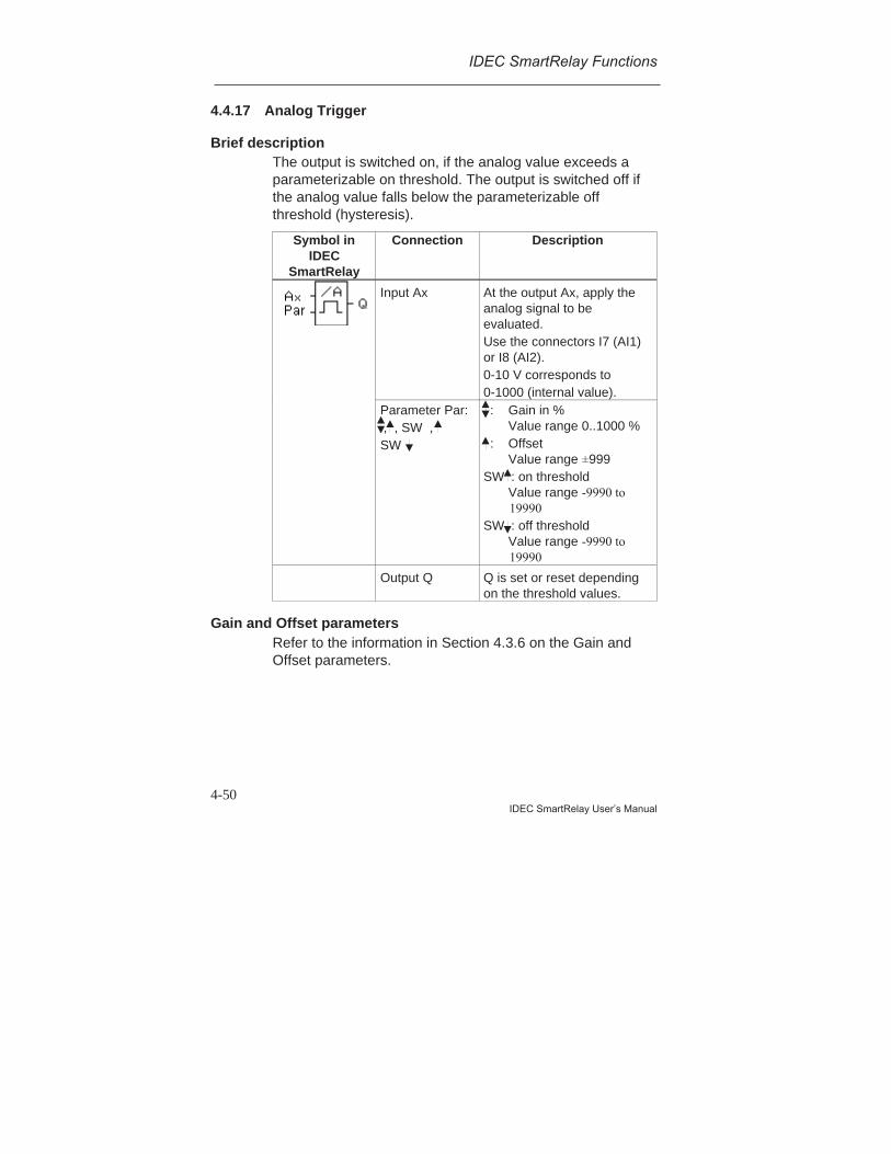
IDEC SmartRelay Functions
4-50IDEC SmartRelay User’s Manual
4.4.17 Analog Trigger
Brief descriptionThe output is switched on, if the analog value exceeds aparameterizable on threshold. The output is switched off ifthe analog value falls below the parameterizable offthreshold (hysteresis).
Symbol inIDEC
SmartRelay
Connection Description
Input Ax At the output Ax, apply theanalog signal to beevaluated.Use the connectors I7 (AI1)or I8 (AI2).0-10 V corresponds to0-1000 (internal value).
Parameter Par: , , SW ,SW
: Gain in %Value range 0..1000 %
: OffsetValue range ±999
SW : on thresholdValue range -9990 to
19990SW : off threshold
Value range -9990 to 19990
Output Q Q is set or reset dependingon the threshold values.
Gain and Offset parametersRefer to the information in Section 4.3.6 on the Gain andOffset parameters.
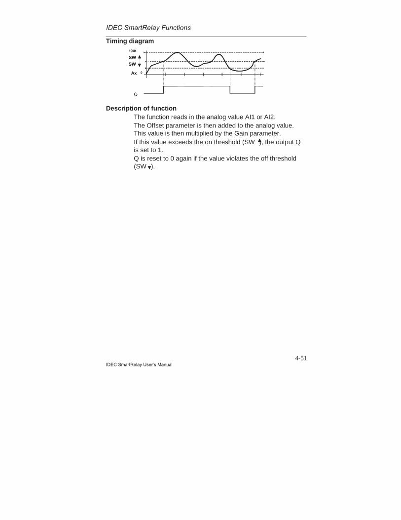
IDEC SmartRelay Functions
4-51IDEC SmartRelay User’s Manual
Timing diagram
Q
1000
0Ax
SW
SW
Description of functionThe function reads in the analog value AI1 or AI2.The Offset parameter is then added to the analog value.This value is then multiplied by the Gain parameter.If this value exceeds the on threshold (SW ), the output Qis set to 1.Q is reset to 0 again if the value violates the off threshold(SW ).
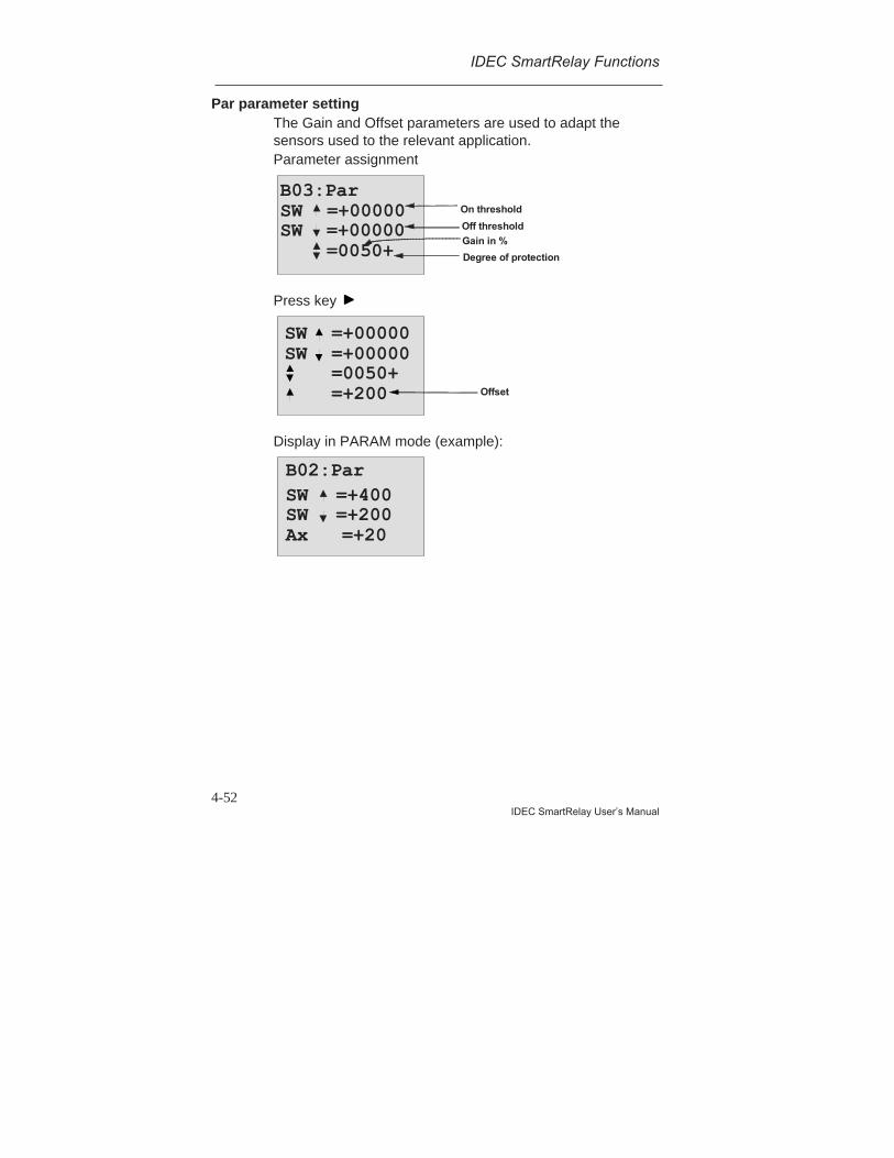
IDEC SmartRelay Functions
4-52IDEC SmartRelay User’s Manual
Par parameter settingThe Gain and Offset parameters are used to adapt thesensors used to the relevant application.Parameter assignment
B03:ParSW =+00000SW =+00000
=0050+Gain in %
Degree of protection
On threshold
Off threshold
Press key
Offset
SW =+00000SW =+00000
=0050+=+200
Display in PARAM mode (example):
B02:ParSW =+400SW =+200Ax =+20
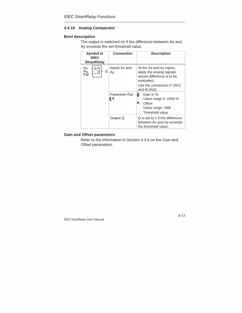
IDEC SmartRelay Functions
4-53IDEC SmartRelay User’s Manual
4.4.18 Analog Comparator
Brief descriptionThe output is switched on if the difference between Ax andAy exceeds the set threshold value.
Symbol inIDEC
SmartRelay
Connection Description
Inputs Ax andAy
At the Ax and Ay inputs,apply the analog signalswhose difference is to beevaluated.Use the connectors I7 (AI1)and I8 (AI2).
Parameter Par: , ,
: Gain in %Value range 0..1000 %
: OffsetValue range ±999
: Threshold value
Output Q Q is set to 1 if the differencebetween Ax and Ay exceedsthe threshold value.
Gain and Offset parametersRefer to the information in Section 4.3.6 on the Gain andOffset parameters.
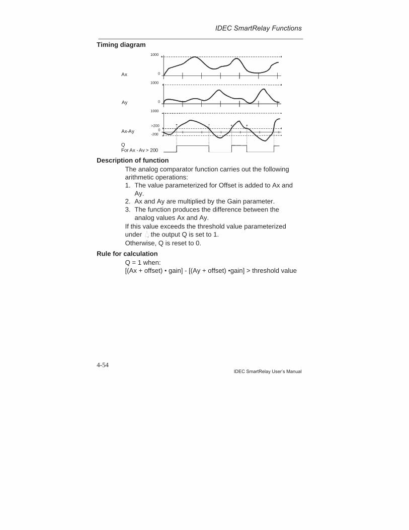
IDEC SmartRelay Functions
4-54IDEC SmartRelay User’s Manual
Timing diagram
Q For Ax - Ay > 200
Ax
1000
0
Ay
1000
0
Ax-Ay
1000
0>200
-200
Description of functionThe analog comparator function carries out the followingarithmetic operations:1. The value parameterized for Offset is added to Ax and
Ay.2. Ax and Ay are multiplied by the Gain parameter.3. The function produces the difference between the
analog values Ax and Ay.If this value exceeds the threshold value parameterizedunder , the output Q is set to 1.Otherwise, Q is reset to 0.
Rule for calculationQ = 1 when:[(Ax + offset) • gain] - [(Ay + offset) •gain] > threshold value
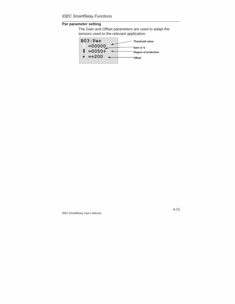
IDEC SmartRelay Functions
4-55IDEC SmartRelay User’s Manual
Par parameter settingThe Gain and Offset parameters are used to adapt thesensors used to the relevant application.
B03:Par=00000=0050+=+200
Gain in %
Degree of protection
Threshold value
Offset
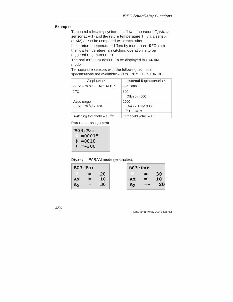
IDEC SmartRelay Functions
4-56IDEC SmartRelay User’s Manual
ExampleTo control a heating system, the flow temperature Tv (via asensor at AI1) and the return temperature Tr (via a sensorat AI2) are to be compared with each other.If the return temperature differs by more than 15 oC fromthe flow temperature, a switching operation is to betriggered (e.g. burner on).The real temperatures are to be displayed in PARAMmode.Temperature sensors with the following technicalspecifications are available: -30 to +70 oC, 0 to 10V DC.
Application Internal Representation
-30 to +70 oC = 0 to 10V DC 0 to 1000
0 oC 300Offset = -300
Value range:-30 to +70 oC = 100
1000Gain = 100/1000
= 0.1 = 10 %
Switching threshold = 15 oC Threshold value = 15
Parameter assignment
B03:Par=00015=0010+=-300
Display in PARAM mode (examples):
B03:Par = 20
Ax = 10Ay = 30
B03:Par = 30
Ax = 10Ay =- 20
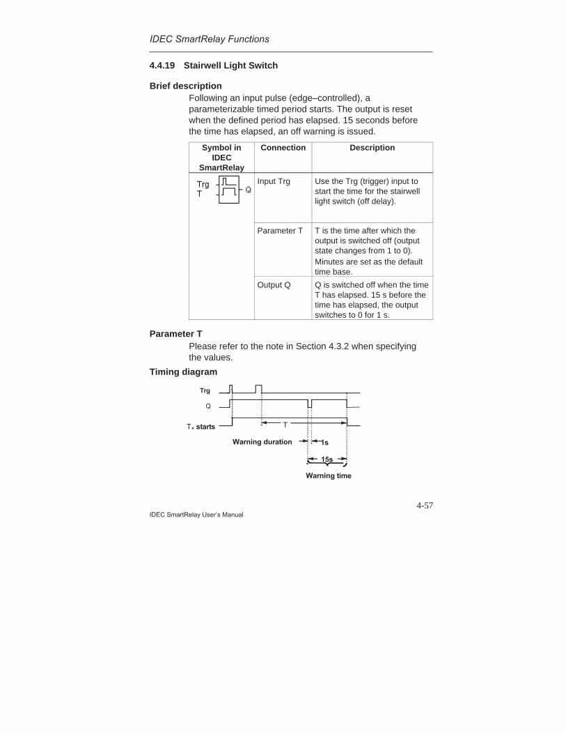
IDEC SmartRelay Functions
4-57IDEC SmartRelay User’s Manual
4.4.19 Stairwell Light Switch
Brief descriptionFollowing an input pulse (edge–controlled), aparameterizable timed period starts. The output is resetwhen the defined period has elapsed. 15 seconds beforethe time has elapsed, an off warning is issued.
Symbol inIDEC
SmartRelay
Connection Description
Input Trg Use the Trg (trigger) input tostart the time for the stairwelllight switch (off delay).
Parameter T T is the time after which theoutput is switched off (outputstate changes from 1 to 0).Minutes are set as the defaulttime base.
Output Q Q is switched off when the timeT has elapsed. 15 s before thetime has elapsed, the outputswitches to 0 for 1 s.
Parameter TPlease refer to the note in Section 4.3.2 when specifyingthe values.
Timing diagram
15s
T a starts T
1s
Q
Trg
Warning time
Warning duration

IDEC SmartRelay Functions
4-58IDEC SmartRelay User’s Manual
Description of functionIf the state of the input Trg changes from 1 to 0, the currenttime Ta starts and the output Q is set to 1.15 s before Ta reaches the time T, the output Q is set to 0for 1 s.If the time Ta reaches the time T, the output Q is reset to 0.Another switch at the input Trg during Ta resets Ta (retriggeroption).In the event of a power failure, the elapsed time is reset.
Changing the time baseYou can also set other values for the warning time andwarning duration .
Time Base T Warning Time WarningDuration
Seconds* 750 ms 50 ms
Minutes 15 s 1 s
Hours 15 min 1 min
*Only relevant for programs with a cycle time of < 25 ms
See also ”Determining the Cycle Time” in Appendix C.
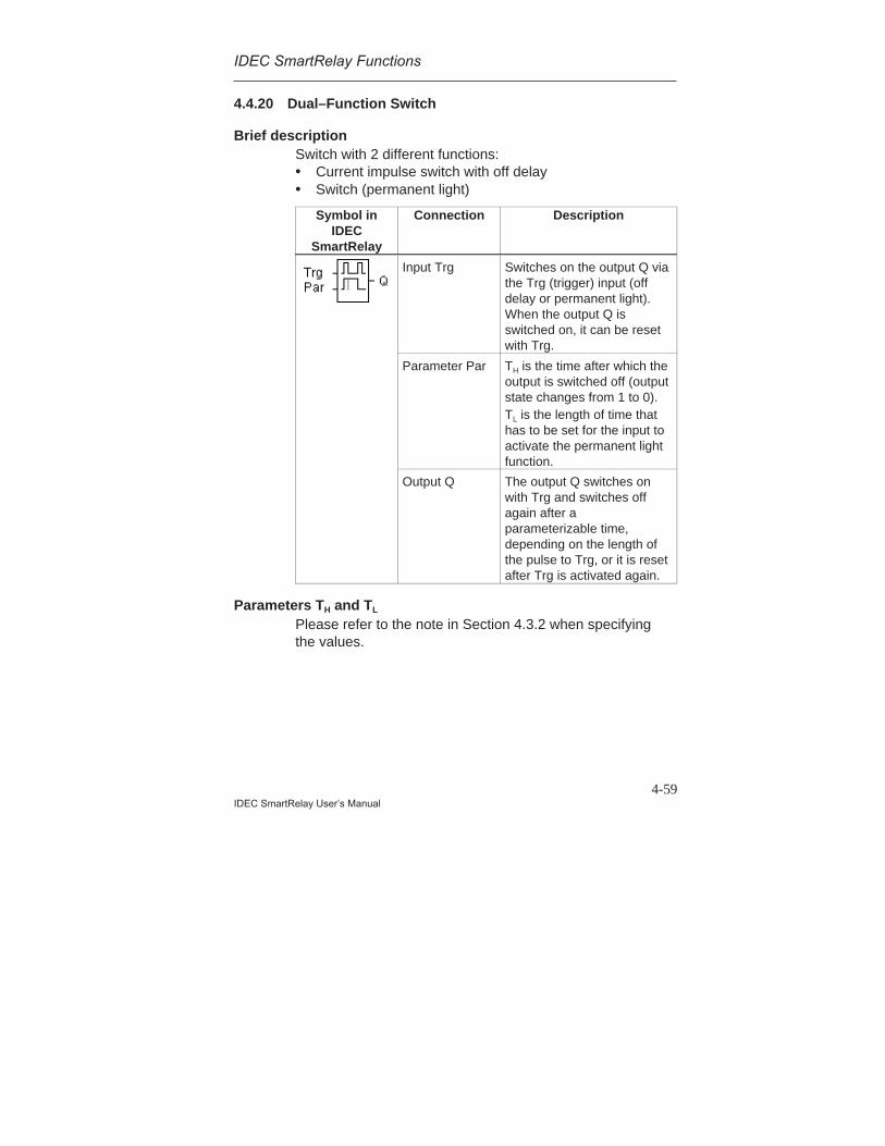
IDEC SmartRelay Functions
4-59IDEC SmartRelay User’s Manual
4.4.20 Dual–Function Switch
Brief descriptionSwitch with 2 different functions:• Current impulse switch with off delay• Switch (permanent light)
Symbol inIDEC
SmartRelay
Connection Description
Input Trg Switches on the output Q viathe Trg (trigger) input (offdelay or permanent light).When the output Q isswitched on, it can be resetwith Trg.
Parameter Par TH is the time after which theoutput is switched off (outputstate changes from 1 to 0).TL is the length of time thathas to be set for the input toactivate the permanent lightfunction.
Output Q The output Q switches onwith Trg and switches offagain after aparameterizable time,depending on the length ofthe pulse to Trg, or it is resetafter Trg is activated again.
Parameters TH and TL
Please refer to the note in Section 4.3.2 when specifyingthe values.

IDEC SmartRelay Functions
4-60IDEC SmartRelay User’s Manual
Timing diagram
Description of functionIf the state of the input Trg changes from 0 to 1, the currenttime Ta starts and the output Q is set to 1.If the time Ta reaches the time TH, the output Q is reset to 0.In the event of a power failure, the elapsed time is reset.If the state 0 changes to 1 at the input Trg, and 1 remainsset at least for the time TL, the permanent light function isactivated and the output Q is switched on permanently.If the input Trg is switched again, TH is reset and the outputQ is switched off.
Ta starts TH
Q
TrigTL

IDEC SmartRelay Functions
4-61IDEC SmartRelay User’s Manual
4.4.21 Message Texts
Brief descriptionDisplay of a parameterized message text during RUN.
Symbol inIDEC
SmartRelay
Connection Description
Input En A change in the state from 0to 1 at the En (Enable) inputstarts the output of themessage text.
Parameter P P is the priority of themessage text.
Parameter Par Par is the text for themessage output.
Output Q Q has the same state as theinput En.
LimitationA maximum of 5 message text functions are possible.
Description of functionIf the state at the input changes from 0 to 1, the messagetext you have parameterized is displayed in RUN mode.If the state at the input changes from 1 to 0, the messagetext is not displayed.If several message text functions have been triggered withEn=1, the message with the highest priority is displayed.If you press the key, the low–priority messages aredisplayed as well.You can switch between the standard display and themessage text display using the keys and .
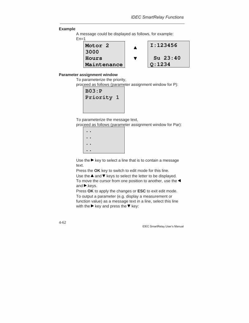
IDEC SmartRelay Functions
4-62IDEC SmartRelay User’s Manual
ExampleA message could be displayed as follows, for example:En=1
Parameter assignment windowTo parameterize the priority,proceed as follows (parameter assignment window for P):
To parameterize the message text,proceed as follows (parameter assignment window for Par):
Use the key to select a line that is to contain a messagetext.Press the OK key to switch to edit mode for this line.Use the and keys to select the letter to be displayed.To move the cursor from one position to another, use the and .keys.Press OK to apply the changes or ESC to exit edit mode.To output a parameter (e.g. display a measurement orfunction value) as a message text in a line, select this linewith the key and press the key:
B03:PPriority 1
Motor 23000HoursMaintenance
I:123456
Su 23:40Q:1234
..
..
..
..
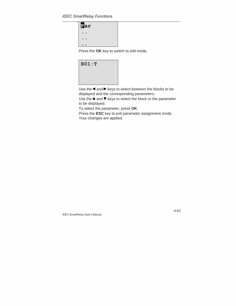
IDEC SmartRelay Functions
4-63IDEC SmartRelay User’s Manual
Press the OK key to switch to edit mode.
Use the and keys to select between the blocks to bedisplayed and the corresponding parameters.Use the and keys to select the block or the parameterto be displayed.To select the parameter, press OK.Press the ESC key to exit parameter assignment mode.Your changes are applied.
B01:T
ar......
P

IDEC SmartRelay Functions
4-64IDEC SmartRelay User’s Manual
5-1IDEC SmartRelay User’s Manual
5 Parameterizing IDEC SmartRelayParameterization sets the parameters of the blocks. Youcan set the delay times for time functions, the switchingtimes for time switches, the threshold value of a counter,the monitoring interval of an operating hours counter andthe on and off thresholds of the threshold switch.You can set the parameters:• In programming mode• In parameterization modeIn parameterization mode the programmer sets a value fora parameter.We introduced parameterization mode so parameters canbe changed without having to change the program. A usercan change the times without having to change intoprogramming mode. The advantage of this is that theprogram (and thus the circuit) is protected but can still bemodified by the user to suit requirements.
Note
IDEC SmartRelay continues to execute the program inparameterization mode.

5-2IDEC SmartRelay User’s Manual
Parameterizing IDEC SmartRelay
5.1 Switching to Parameterization Mode
To switch to parameterization mode, press ESC and OK atthe same time:
IDEC SmartRelay switches to parameterization mode anddisplays the parameterization menu:
The ‘Set Clock’ menu item is executed only if your versionof IDEC SmartRelay has a clock/time switch (thoseversions of IDEC SmartRelay that have a clock have theletter C in their name e. g. FL1A-H10RCB). Set Clockallows you to set IDEC SmartRelay’s time switch.
5.1.1 Parameters
The following can be parameters:• The delay times of a time relay.• The switching times (cams) of a time switch.• The threshold value of a counter.• The monitoring time of an operating hours counter.• The switching thresholds of a threshold switch.
I:123456 Mo 09:00Q:1234
>Set Clock Set Param
ESC OK
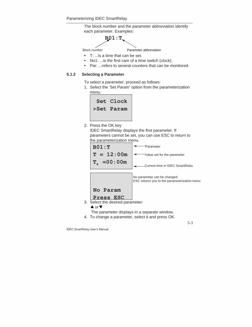
5-3
IDEC SmartRelay User’s Manual
Parameterizing IDEC SmartRelay
The block number and the parameter abbreviation identifyeach parameter. Examples:
• T: ...is a time that can be set.• No1: ...is the first cam of a time switch (clock).• Par: ...refers to several counters that can be monitored.
5.1.2 Selecting a Parameter
To select a parameter, proceed as follows:1. Select the ‘Set Param’ option from the parameterization
menu.
2. Press the OK keyIDEC SmartRelay displays the first parameter. Ifparameters cannot be set, you can use ESC to return tothe parameterization menu.
3. Select the desired parameter: or The parameter displays in a separate window.
4. To change a parameter, select it and press OK.
B01:T
Block number Parameter abbreviation
Set Clock>Set Param
B01:TT = 12:00mTa =00:00m
Parameter
Value set for the parameter
Current time in IDEC SmartRelay
No ParamPress ESC
No parameter can be changed:ESC returns you to the parameterization menu
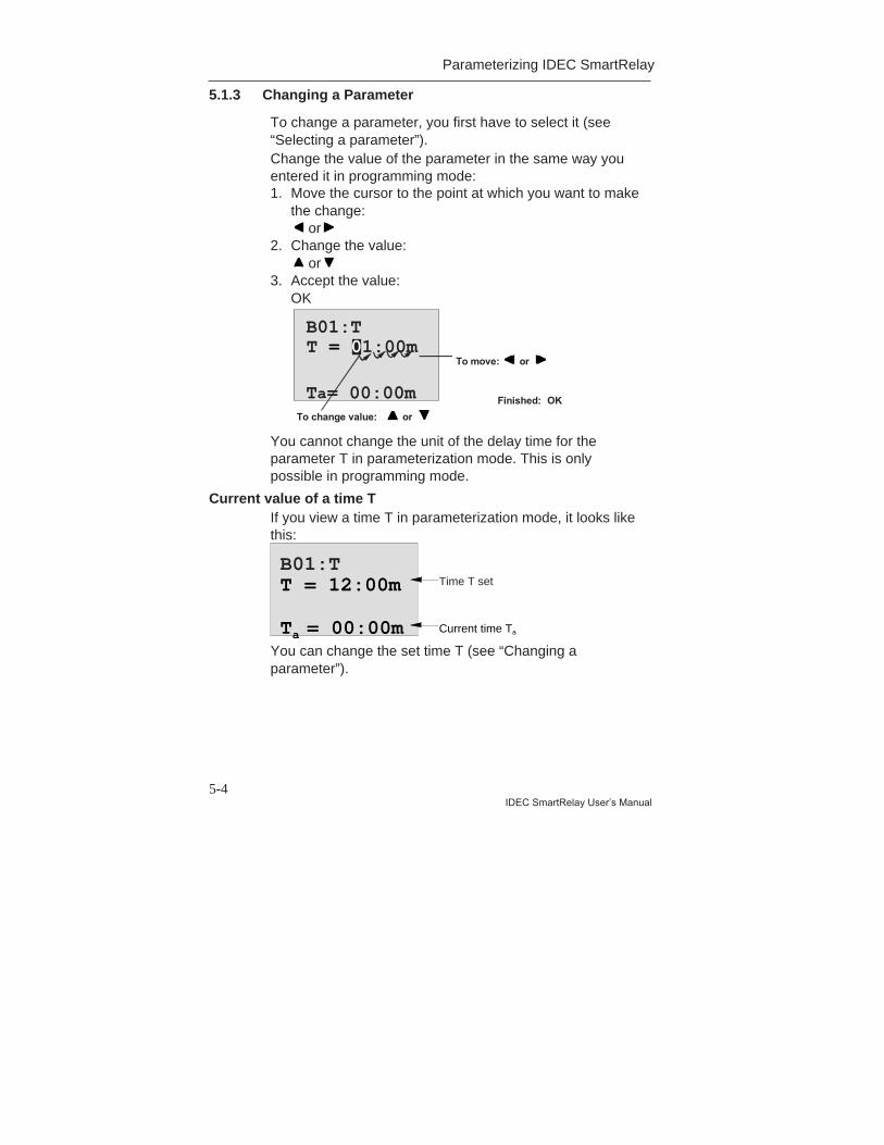
5-4IDEC SmartRelay User’s Manual
Parameterizing IDEC SmartRelay
5.1.3 Changing a Parameter
To change a parameter, you first have to select it (see“Selecting a parameter”).Change the value of the parameter in the same way youentered it in programming mode:1. Move the cursor to the point at which you want to make
the change: or
2. Change the value: or
3. Accept the value:OK
B01:T
Ta= 00:00m
To move: or
To change value: or Finished: OK
T = 01:00m
You cannot change the unit of the delay time for theparameter T in parameterization mode. This is onlypossible in programming mode.
Current value of a time TIf you view a time T in parameterization mode, it looks likethis:
You can change the set time T (see “Changing aparameter”).
B01:T
Ta = 00:00m
T = 12:00m Time T set
Current time Ta

5-5
IDEC SmartRelay User’s Manual
Parameterizing IDEC SmartRelay
Current value of the time switchIf you view a cam of a time switch in parameterizationmode, it looks like this:
IDEC SmartRelay displays the circuit state of the timeswitch rather than the circuit state of a cam. The circuitstate of the time switch depends on all three cams (No1,No 2 and No 3).
The time switch is off (state’0’ at the output)The time switch is on (state’1’ at the output)
B02:No1Day = SuOn = 09:00Off= 10:00
The circuit state of the time switchis displayed:1
0
1
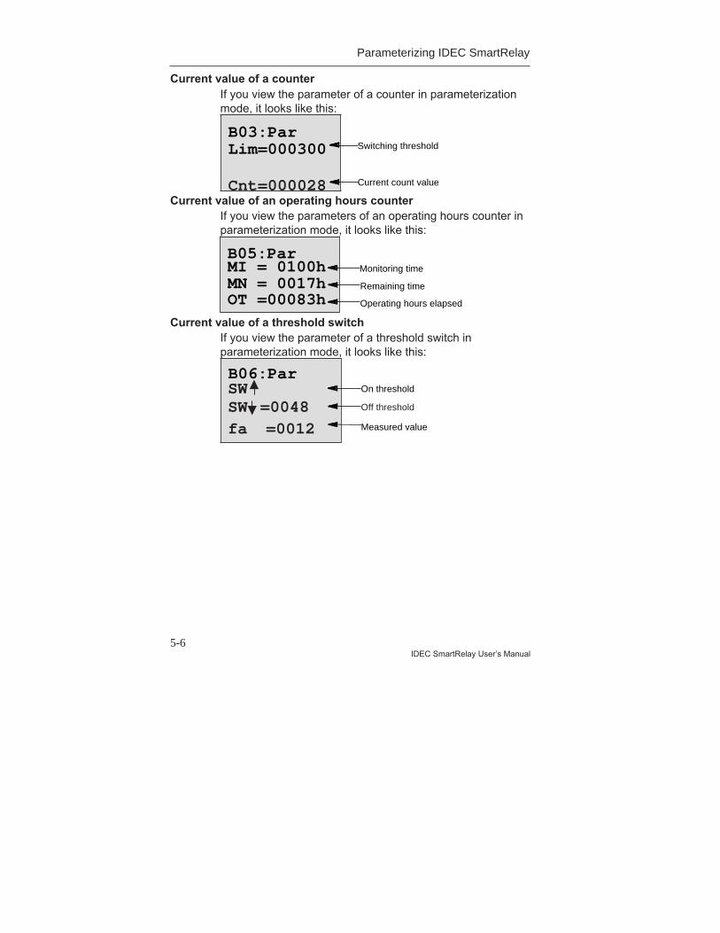
5-6IDEC SmartRelay User’s Manual
Parameterizing IDEC SmartRelay
Current value of a counterIf you view the parameter of a counter in parameterizationmode, it looks like this:
Current value of an operating hours counterIf you view the parameters of an operating hours counter inparameterization mode, it looks like this:
Current value of a threshold switchIf you view the parameter of a threshold switch inparameterization mode, it looks like this:
Cnt=000028
B05:Par
B06:Par
Lim=000300B03:Par
MI = 0100hMN = 0017hOT =00083h
Off threshold
Switching threshold
Remaining time
Measured value
Current count value
Operating hours elapsed
On threshold
Monitoring time
SWSW =0048fa =0012
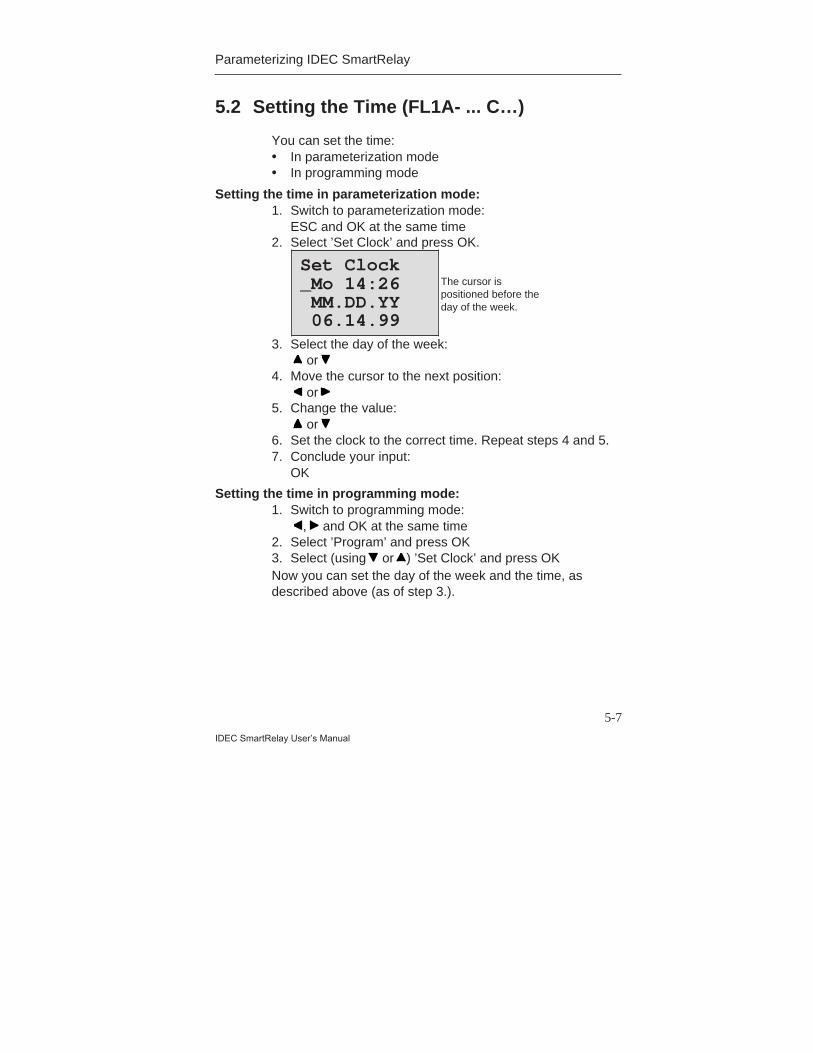
5-7
IDEC SmartRelay User’s Manual
Parameterizing IDEC SmartRelay
5.2 Setting the Time (FL1A- ... C…)
You can set the time:• In parameterization mode• In programming mode
Setting the time in parameterization mode:1. Switch to parameterization mode:
ESC and OK at the same time2. Select ’Set Clock’ and press OK.
3. Select the day of the week: or
4. Move the cursor to the next position: or
5. Change the value: or
6. Set the clock to the correct time. Repeat steps 4 and 5.7. Conclude your input:
OK
Setting the time in programming mode:1. Switch to programming mode:
, and OK at the same time2. Select ’Program’ and press OK3. Select (using or ) ’Set Clock’ and press OKNow you can set the day of the week and the time, asdescribed above (as of step 3.).
Set Clock_Mo 14:26MM.DD.YY06.14.99
The cursor ispositioned before theday of the week.
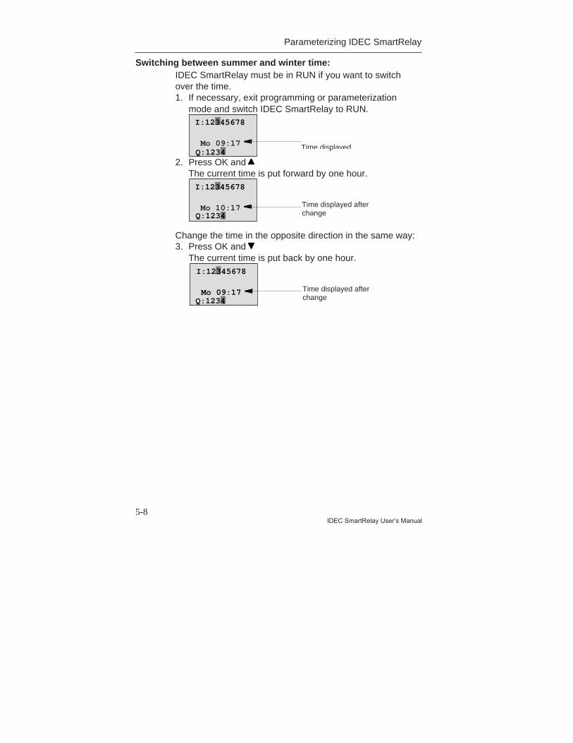
5-8IDEC SmartRelay User’s Manual
Parameterizing IDEC SmartRelay
Switching between summer and winter time:IDEC SmartRelay must be in RUN if you want to switchover the time.1. If necessary, exit programming or parameterization
mode and switch IDEC SmartRelay to RUN.
2. Press OK and The current time is put forward by one hour.
Change the time in the opposite direction in the same way:3. Press OK and
The current time is put back by one hour.
Time displayed
Time displayed afterchange
Mo 09:17
I:12345678
Q:1234
Mo 09:17
I:12345678
Q:1234
Time displayed afterchange
Mo 10:17
I:12345678
Q:1234
6-1IDEC SmartRelay User’s Manual
6 IDEC SmartRelay MemoryCartridge
You can keep only one program stored in IDECSmartRelay. If you want to change the program or writeanother program without deleting the first one, you mustarchive it somewhere. You must archive it to a memorycartridge.You can copy the program stored in IDEC SmartRelay to amemory cartridge. You can insert the memory cartridge in adifferent IDEC SmartRelay and copy the program to theother IDEC SmartRelay. You can use the memory cartridgeto do the following:• Archive programs• Duplicate programs• Send programs by ground mail• Write and test programs in the office and then transfer
them to a different IDEC SmartRelay in the cabinet.IDEC SmartRelay is supplied with a cover. You must orderthe memory cartridge separately.
NoteYou do not require a memory cartridge for permanently
storing the program in your IDEC SmartRelay.The IDEC SmartRelay program is already stored
permanently when programming mode is finished.
Below you will find the two memory cartridges available for IDECSmartRelay. Both can accommodate the entire program memory of aIDEC SmartRelay.
Memory Cartridge Type No.
Memory cartridge (Yellow) : forcopying
FL1A-PM1
Memory cartridge (Red) : withknow–how protection and copyprotection
FL1A-PM2
IDEC SmartRelay Program Module
6-2IDEC SmartRelay User’s Manual
Memory Cartridge (Yellow)You can read and write programs with this memorycartridge.
Memory Cartridge (Red)You can only write programs with this memory cartridge.Once a program has been stored, it cannot be looked at,copied or changed (i.e. your data is protected).Programs saved like this can only be run if the moduleremains inserted in IDEC SmartRelay while the system is inoperation.
!Warning
Do not save your program on a memory cartridge
with program protection if you intend to edit itfurther.
You can start up a program on a memorycartridge with know-how protection but not read
it for the purpose of editing.
6.2 Removing and Inserting ProgramMemory Cartridge
When you remove a red memory cartridge (know–howprotection and copy protection), always remember that theprogram stored on the memory cartridge can only run if thememory cartridge is inserted and remains inserted for theentire time.If the memory cartridge is removed, IDEC SmartRelaydisplays the message ’no program’. Removing the redmemory cartridge during operation leads to impermissibleoperating statuses.Always heed the following warning:
6-3IDEC SmartRelay User’s Manual
IDEC SmartRelay Program Module
!Warning
Do not put your finger or an object made of metal
or any other conductive material in the open
shaft of the memory cartridge.
The socket for the memory cartridge may be live
if L1 and N have been incorrectly wired.
Only a trained technician should change thememory cartridge.
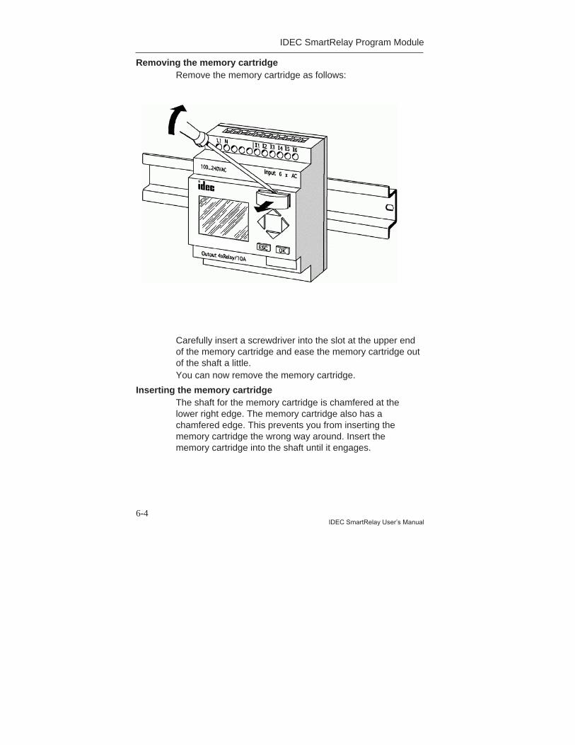
IDEC SmartRelay Program Module
6-4IDEC SmartRelay User’s Manual
Removing the memory cartridgeRemove the memory cartridge as follows:
Carefully insert a screwdriver into the slot at the upper endof the memory cartridge and ease the memory cartridge outof the shaft a little.You can now remove the memory cartridge.
Inserting the memory cartridgeThe shaft for the memory cartridge is chamfered at thelower right edge. The memory cartridge also has achamfered edge. This prevents you from inserting thememory cartridge the wrong way around. Insert thememory cartridge into the shaft until it engages.

6-5IDEC SmartRelay User’s Manual
IDEC SmartRelay Program Module
6.3 Copying a Program from IDECSmartRelay to the Memory Cartridge
To copy a program to the memory cartridge, proceed asfollows:1. Insert the memory cartridge into the shaft.2. Switch IDEC SmartRelay to programming mode:
, and OK at the same time
3. Move the ’>’ to ”PC/Card”:
4. Press OK. The transfer menu appears.
5. Move the ’>’ to ’IDEC SmartRelay -> Card’:
6. Press OK.
IDEC SmartRelay copies the program to the memorycartridge.When IDEC SmartRelay has finished copying, itautomatically returns to the main menu:
>Program.. PC/Card.. Start
Program..>PC/Card..Start
= IDECSmartRelay
>PC↔ →Card
Card→
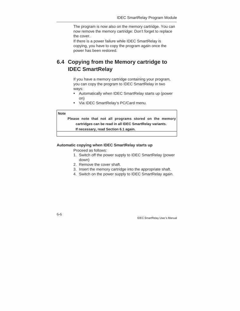
IDEC SmartRelay Program Module
6-6IDEC SmartRelay User’s Manual
The program is now also on the memory cartridge. You cannow remove the memory cartridge: Don’t forget to replacethe cover.If there is a power failure while IDEC SmartRelay iscopying, you have to copy the program again once thepower has been restored.
6.4 Copying from the Memory cartridge toIDEC SmartRelay
If you have a memory cartridge containing your program,you can copy the program to IDEC SmartRelay in twoways:• Automatically when IDEC SmartRelay starts up (power
on)• Via IDEC SmartRelay’s PC/Card menu.
Note Please note that not all programs stored on the memory
cartridges can be read in all IDEC SmartRelay variants.
If necessary, read Section 6.1 again.
Automatic copying when IDEC SmartRelay starts upProceed as follows:1. Switch off the power supply to IDEC SmartRelay (power
down)2. Remove the cover shaft.3. Insert the memory cartridge into the appropriate shaft.4. Switch on the power supply to IDEC SmartRelay again.
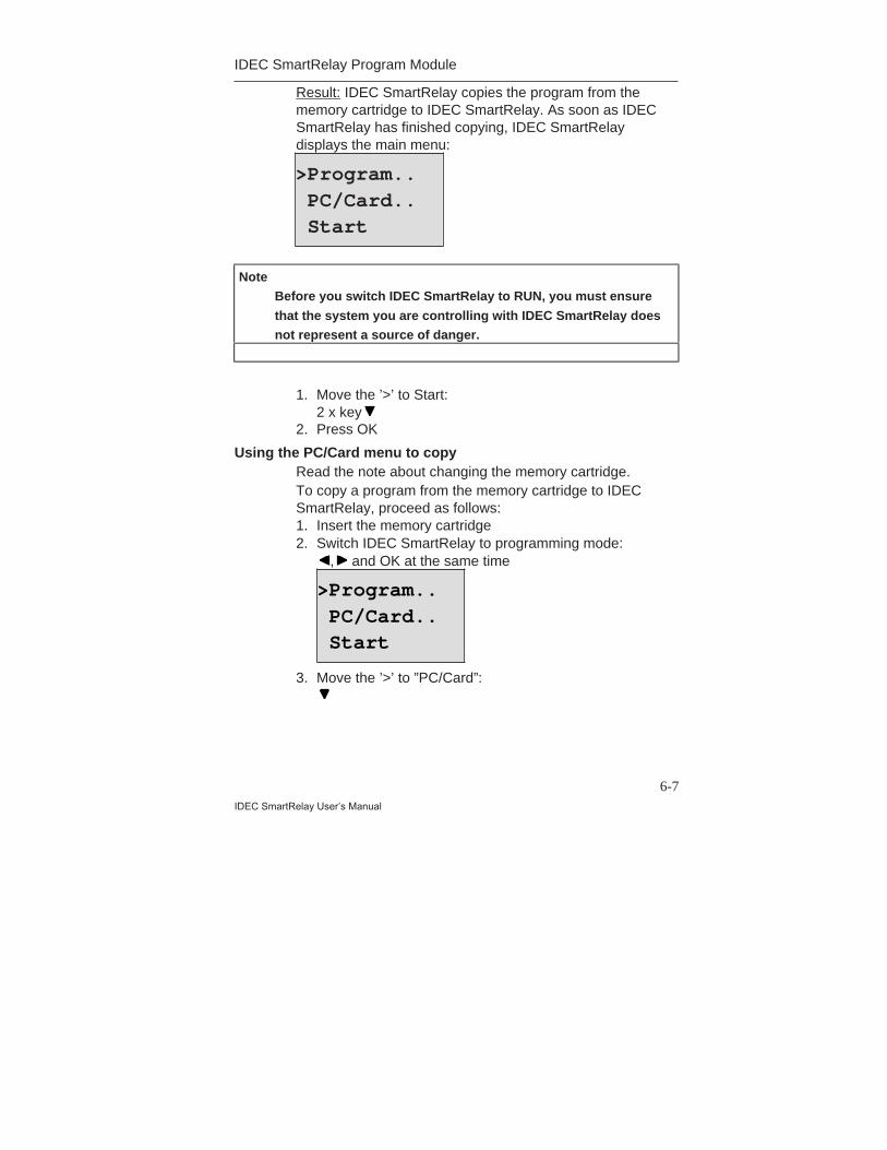
6-7IDEC SmartRelay User’s Manual
IDEC SmartRelay Program Module
Result: IDEC SmartRelay copies the program from thememory cartridge to IDEC SmartRelay. As soon as IDECSmartRelay has finished copying, IDEC SmartRelaydisplays the main menu:
Note Before you switch IDEC SmartRelay to RUN, you must ensure
that the system you are controlling with IDEC SmartRelay does not represent a source of danger.
1. Move the ’>’ to Start:2 x key
2. Press OK
Using the PC/Card menu to copyRead the note about changing the memory cartridge.To copy a program from the memory cartridge to IDECSmartRelay, proceed as follows:1. Insert the memory cartridge2. Switch IDEC SmartRelay to programming mode:
, and OK at the same time
3. Move the ’>’ to ”PC/Card”:
>Program..PC/Card..Start
>Program.. PC/Card.. Start
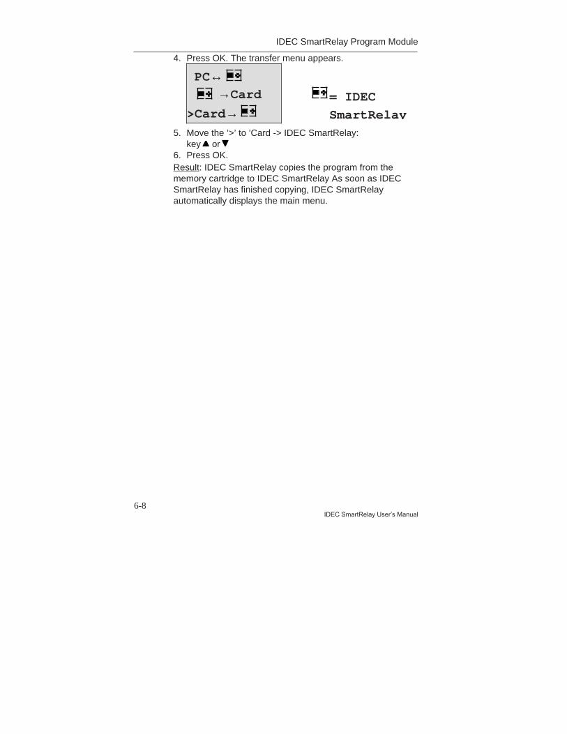
IDEC SmartRelay Program Module
6-8IDEC SmartRelay User’s Manual
4. Press OK. The transfer menu appears.
5. Move the ’>’ to ’Card -> IDEC SmartRelay:key or
6. Press OK.Result: IDEC SmartRelay copies the program from thememory cartridge to IDEC SmartRelay As soon as IDECSmartRelay has finished copying, IDEC SmartRelayautomatically displays the main menu.
PC↔ →Card
>Card→= IDEC
SmartRelay
7-1IDEC SmartRelay User’s Manual
7 IDEC SmartRelay SoftwareThe program WindLGC is available as a programmingpackage for the PC. The software has the followingfunctions:• Offline program generation of your application• Simulation of your circuit (or program) on the computer• Generation and printing of a block diagram of the circuit• Saving the program to the hard disk or another storage
medium• Program transfer
- From IDEC SmartRelay to the PC- From the PC to IDEC SmartRelay
The IDEC SmartRelay alternativeThe IDEC SmartRelay programming software representsan alternative to the conventional means of planning:1. Develop your applications at your desk.2. Simulate the application in your computer and test
whether or not it functions properly before the circuit isactually put to use.
3. Print out the entire circuit in a block diagram or inseveral block diagrams sorted according to outputs.
4. Archive your circuits in your PC file system. In this wayyou can retrieve a circuit directly if you want to makechanges some time in the future.
5. Transfer the program to IDEC SmartRelay by pressingjust a few buttons. Your IDEC SmartRelay is retooledwithin a very short space of time.

IDEC SmartRelay Software
7-2IDEC SmartRelay User’s Manual
7.1 Possible Applications for IDECSmartRelay Software
System requirementsThe following requirements have to be met in order to runWindLGC:• IBM–compatible PC• Pentium 90 or higher
(Pentium 133 recommended)• 32 MB RAM
(64 MB RAM recommended)• 90 MB of free hard disk space• Microsoft Windows 95/98 or NT4.0• SVGA graphics card, resolution 800x600, 256 colors
(1024x768 recommended)• CD–ROM drive + mouse
Installation and operationBefore installation, read the product informationdocumentation and the text files on the CD–ROM.To install the software, simply follow the instructions on theinstallation program. To start the installation program,proceed as follows (installation on CD–ROM should startautomatically):1. Select and start SETUP.EXE
in Windows 95/98 and Windows NT 4.0 either bychoosing Start/Run and entering the line: [drive]:\Setupor by clicking it in Windows Explorer.
2. Follow the instructions in the installation program.If you have any questions, use the online software helpsystem.
The next stepsIn the next step we will show you how to connect IDECSmartRelay to a PC. Omit this step if you currently haveonly the software available.
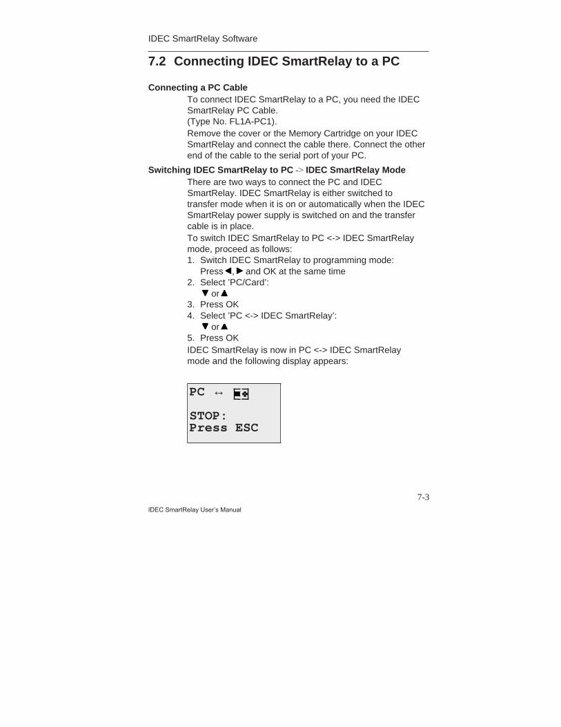
IDEC SmartRelay Software
7-3IDEC SmartRelay User’s Manual
7.2 Connecting IDEC SmartRelay to a PC
Connecting a PC CableTo connect IDEC SmartRelay to a PC, you need the IDECSmartRelay PC Cable.(Type No. FL1A-PC1).Remove the cover or the Memory Cartridge on your IDECSmartRelay and connect the cable there. Connect the otherend of the cable to the serial port of your PC.
Switching IDEC SmartRelay to PC -> IDEC SmartRelay ModeThere are two ways to connect the PC and IDECSmartRelay. IDEC SmartRelay is either switched totransfer mode when it is on or automatically when the IDECSmartRelay power supply is switched on and the transfercable is in place.To switch IDEC SmartRelay to PC <-> IDEC SmartRelaymode, proceed as follows:1. Switch IDEC SmartRelay to programming mode:
Press , and OK at the same time2. Select ’PC/Card’:
or 3. Press OK4. Select ’PC <-> IDEC SmartRelay’:
or 5. Press OKIDEC SmartRelay is now in PC <-> IDEC SmartRelaymode and the following display appears:
PC ↔
STOP:Press ESC

IDEC SmartRelay Software
7-4IDEC SmartRelay User’s Manual
To switch IDEC SmartRelay automatically to PC <-> IDECSmartRelay mode, proceed as follows:1. Switch off the power supply to IDEC SmartRelay.2. Remove the cover or the Memory Cartridge and
connect the cable there.3. Switch the power back on.IDEC SmartRelay automatically goes into PC <-> IDECSmartRelay mode.The PC can now access IDEC SmartRelay. Find out how todo this on the online help system of the IDEC SmartRelaysoftware.You can interrupt the connection to the PC using ESC onIDEC SmartRelay.
7.3 Transfer Settings
To transfer programs between the PC and IDECSmartRelay, you must make certain settings in the IDECSmartRelay software. You can make these settings usingthe menu of the software you are using.
WindLGC• Specify which IDEC SmartRelay: WindLGC works out
which IDEC SmartRelay variant you will need to use thewritten program.
• Options -> Interface: You can enter the serial port towhich IDEC SmartRelay is connected. You can also findout the correct port automatically (the program checkseach port for a connected IDEC SmartRelay).
• Transfer: PC -> IDEC SmartRelay: Use this to transfera program you have created in WindLGC to IDECSmartRelay.
• Transfer: IDEC SmartRelay -> PC: Use this to transfera program you have created in IDEC SmartRelay toWindLGC.
8-1IDEC SmartRelay User’s Manual
8 ApplicationsTo give you an idea of the kind of situations in which youcan use IDEC SmartRelay, we have compiled a number ofapplication examples. We have included the circuit diagramof the original solution for each example and compared itwith the solutions using IDEC SmartRelay.You can find solutions for the following tasks:8.1 Stairway or hall lighting 8-28.2 Automatic door 8-78.3 Ventilation system 8-148.4 Industrial gate 8-198.5 Fluorescent lights 8-238.6 Water pump 8-278.7 Further applications 8-31
Note
The IDEC SmartRelay applications are provided free ofcharge to our customers. The examples they contain are
not binding and are included to provide generalinformation on how IDEC SmartRelay can be used.
Customer-specific solutions may be different.
The user is responsible for ensuring that the system
operates properly. It must comply with any and allapplicable local standards and system-related installation
regulations.
Errors are excepted and the right to make changes
reserved.
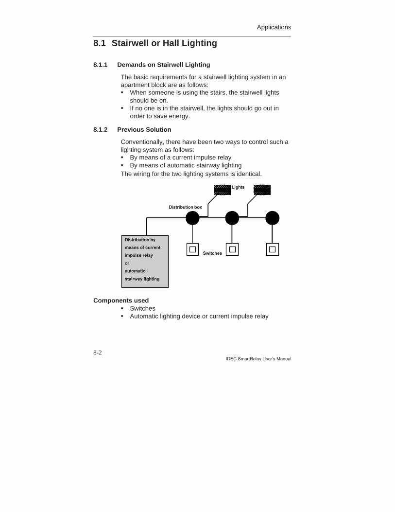
Applications
8-2IDEC SmartRelay User’s Manual
8.1 Stairwell or Hall Lighting
8.1.1 Demands on Stairwell Lighting
The basic requirements for a stairwell lighting system in anapartment block are as follows:• When someone is using the stairs, the stairwell lights
should be on.• If no one is in the stairwell, the lights should go out in
order to save energy.
8.1.2 Previous Solution
Conventionally, there have been two ways to control such alighting system as follows:• By means of a current impulse relay• By means of automatic stairway lightingThe wiring for the two lighting systems is identical.
Lights
Switches
Distribution by
means of current
impulse relay
or
automatic
stairway lighting
Distribution box
Components used• Switches• Automatic lighting device or current impulse relay
Applications
8-3IDEC SmartRelay User’s Manual
Lighting system with a current impulse relayWhen a current impulse relay is used, the lighting systembehaves as follows:• When any switch is pressed: the lighting is switched on• When any switch is pressed again: the lighting is
switched offDisadvantage: people frequently forget to switch the lightsoff.
Lighting system with an automatic lighting deviceWhen an automatic device is used, the lighting systembehaves as follows:• When any switch is pressed: the lighting is switched on• When the preset time has elapsed, the lights switch off
automatically.Disadvantage: The lighting cannot be switched on for anextended period of time (e.g. for cleaning purposes). Thepermanent on switch is usually on the stairwell lightingtimer unit which may be difficult or impossible to access.
8.1.3 Lighting System with IDEC SmartRelay
You can use a IDEC SmartRelay module to replace thestairwell lighting timer or the current impulse relay. And youcan implement both functions (timed off delay and currentimpulse relay) in a single unit. What is more, you canincorporate extra functions without making any alterationsto the wiring. Here are some examples:• Current impulse relay with IDEC SmartRelay• Automatic stairway lighting system with IDEC
SmartRelay• IDEC SmartRelay as a multifunctional switching system
with the following functions:- Light on: Press switch
(Light switches off after the set time elapses)- Permanent light on: Press switch twice- Light off: Press switch for 2 seconds
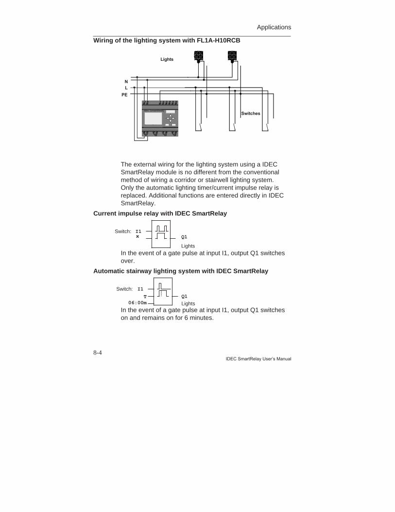
Applications
8-4IDEC SmartRelay User’s Manual
Wiring of the lighting system with FL1A-H10RCB
Lights
Switches
L1 N I1 I2 I3 I4 I5 I6
Q1 Q2 Q3 Q4
idec
LN
PE
SmartRelay
The external wiring for the lighting system using a IDECSmartRelay module is no different from the conventionalmethod of wiring a corridor or stairwell lighting system.Only the automatic lighting timer/current impulse relay isreplaced. Additional functions are entered directly in IDECSmartRelay.
Current impulse relay with IDEC SmartRelay
In the event of a gate pulse at input I1, output Q1 switchesover.
Automatic stairway lighting system with IDEC SmartRelay
In the event of a gate pulse at input I1, output Q1 switcheson and remains on for 6 minutes.
I1Switch:Q1
Lights
x
I1Switch:Q1
LightsT
06:00m
idec SmartRelay

Applications
8-5IDEC SmartRelay User’s Manual
Multifunctional switch with IDEC SmartRelaySwitch light on
Switch permanentlight on
Switch light off
Off delay
Latching relay
Current impulse relay
On delay
&&x T
02.00sx
T
02.00 s
≥ 1
T06:00m
xQ1
Q1
I1
I1
I1
I1
lo
The diagram shows the circuit for an input with anassociated output.This switch has the following options:• When the switch is pressed: The light is switched on
and goes off again after the set time of 6 minutes(T=06:00m) has elapsed (off delay)
• When the switch is pressed twice: The light isswitched on permanently (the latching relay is set viathe current impulse relay).
• When the switch is pressed for 2 seconds: The lightis switched off (on delay switches off both thepermanent light and the normal light; this branch of thecircuit is used twice).
You can enter these circuits several times for the remaininginputs and outputs. Instead of using 4 automatic stairwaylighting systems or 4 current impulse relays, you thus useonly a single IDEC SmartRelay. You could also use thefree inputs and outputs for completely different functions.
Applications
8-6IDEC SmartRelay User’s Manual
8.1.4 Special Features and Enhancement Options
Features such as the following are available for addingfunctions or saving energy:• You can have the light flash before it goes off
automatically.• You can integrate various central functions:
- Central off- Central on (panic button)- Control of all lights or individual circuits by a daylight
control switch- Control by the integrated time switch
(e.g. permanent light only until 24.00 hours; noenabling at certain times)
- Automatic switching off of the permanent light after apreset time has elapsed (e.g. after 3 hours)
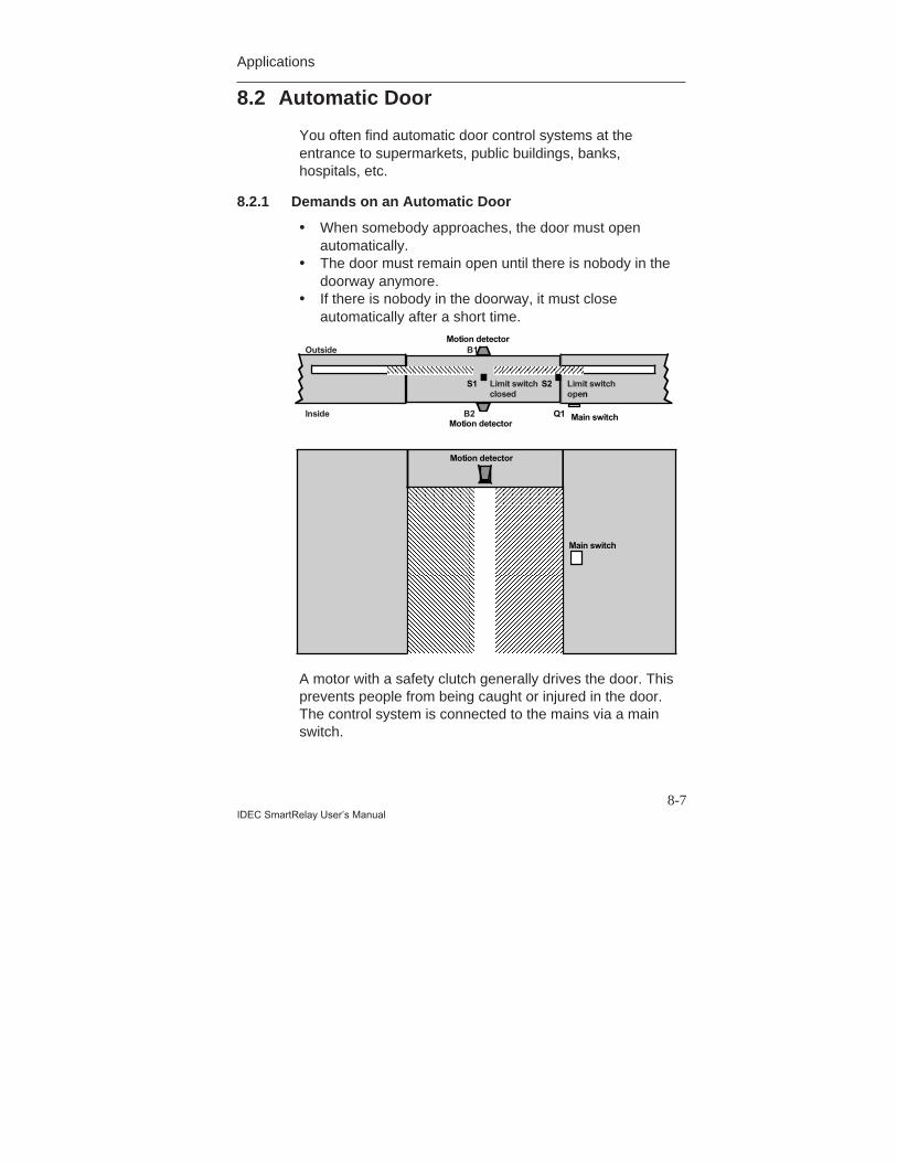
Applications
8-7IDEC SmartRelay User’s Manual
8.2 Automatic Door
You often find automatic door control systems at theentrance to supermarkets, public buildings, banks,hospitals, etc.
8.2.1 Demands on an Automatic Door
• When somebody approaches, the door must openautomatically.
• The door must remain open until there is nobody in thedoorway anymore.
• If there is nobody in the doorway, it must closeautomatically after a short time.
Outside
Inside
B1
B2
Limit switchclosed
Limit switchopen
Main switch
Q1
S1 S2
Motion detector
Main switch
Motion detector
Motion detector
A motor with a safety clutch generally drives the door. Thisprevents people from being caught or injured in the door.The control system is connected to the mains via a mainswitch.
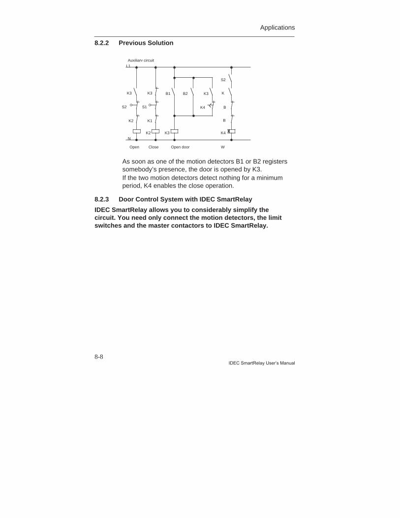
Applications
8-8IDEC SmartRelay User’s Manual
8.2.2 Previous Solution
As soon as one of the motion detectors B1 or B2 registerssomebody’s presence, the door is opened by K3.If the two motion detectors detect nothing for a minimumperiod, K4 enables the close operation.
8.2.3 Door Control System with IDEC SmartRelay
IDEC SmartRelay allows you to considerably simplify thecircuit. You need only connect the motion detectors, the limitswitches and the master contactors to IDEC SmartRelay.
K2
K2 K1
K3 K3
Open Close
S2 S1
K3
B1 B2 K3
K4
K4
B
K
B
S2
Open door W
Auxiliary circuitL1
N
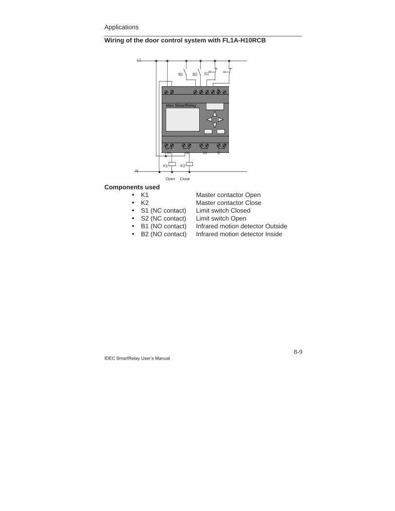
Applications
8-9IDEC SmartRelay User’s Manual
Wiring of the door control system with FL1A-H10RCB
Components used• K1 Master contactor Open• K2 Master contactor Close• S1 (NC contact) Limit switch Closed• S2 (NC contact) Limit switch Open• B1 (NO contact) Infrared motion detector Outside• B2 (NO contact) Infrared motion detector Inside
N I1 I2 I3 I4 II6
Q1 Q2 Q3 Q
Idec SmartRelay
K1 K2
Open Close
B1 B2 S1
L1
N

Applications
8-10IDEC SmartRelay User’s Manual
Diagram of the door control system with IDEC SmartRelay
&1
1
1
&
I4
I3
Q2
Q1
RS
I1I2
1I4
T=4s
Close
Openx
&x
Q1
Q2
This is the functional block diagram that corresponds to thecircuit diagram of the conventional solution.You can simplify this circuit using IDEC SmartRelay’sfunctions. Use the off delay to replace the latching relayand on delay. The following function block diagramillustrates this simplification:
&1
1
1
&
I4
I3
I1
I2x
Q2
Q1
x10 s
Close
Open
Limit switchDoor closed
Limit switchDoor open
Motiondetector
Q1
Q2
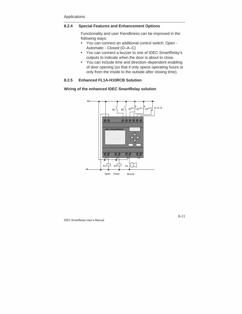
Applications
8-11IDEC SmartRelay User’s Manual
8.2.4 Special Features and Enhancement Options
Functionality and user friendliness can be improved in thefollowing ways:• You can connect an additional control switch: Open -
Automatic - Closed (O–A–C)• You can connect a buzzer to one of IDEC SmartRelay’s
outputs to indicate when the door is about to close.• You can include time and direction–dependent enabling
of door opening (so that it only opens operating hours oronly from the inside to the outside after closing time).
8.2.5 Enhanced FL1A-H10RCB Solution
Wiring of the enhanced IDEC SmartRelay solution
L1 N I1 I2 I3 I4 I5 I6
K1 K2
Open Close
B1 B2 S2S1
L1
N
Buzzer
S3 O–A–G
H1
Q1 Q2 Q3 Q4
Idec SmartRelay
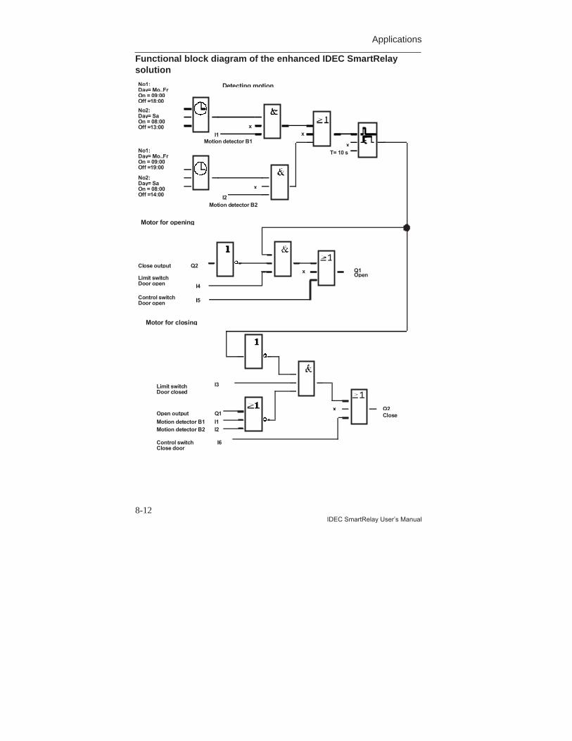
Applications
8-12IDEC SmartRelay User’s Manual
Functional block diagram of the enhanced IDEC SmartRelaysolution
&1
1
1
&
I4
I3
Q2
Q1
RS
I1I2
1I4
T=4s
Close
Openx
&x
Q1
Q2
&1
1
1
&
I4
I3
Q2
Q1
RS
I1I2
1I4
T=4s
Close
Openx
&x
Q1
Q2
x
x
x
x
No1:Day= Mo..FrOn = 09:00Off =18:00
No2:Day= SaOn = 08:00Off =13:00
No1:Day= Mo..FrOn = 09:00Off =19:00
No2:Day= SaOn = 08:00Off =14:00
tput
Motion detector B1Motion detector B2
I3Limit switchDoor closed
I6Control switchClose door
Detecting motion
Motor for opening
Motor for closing
I1
I2
Motion detector B1
Motion detector B2
T= 10 s
x
I5Control switchDoor open
Q2Close output
I4
Limit switchDoor open
Q1Open
Q2Close
xQ1
I1I2
Open ou
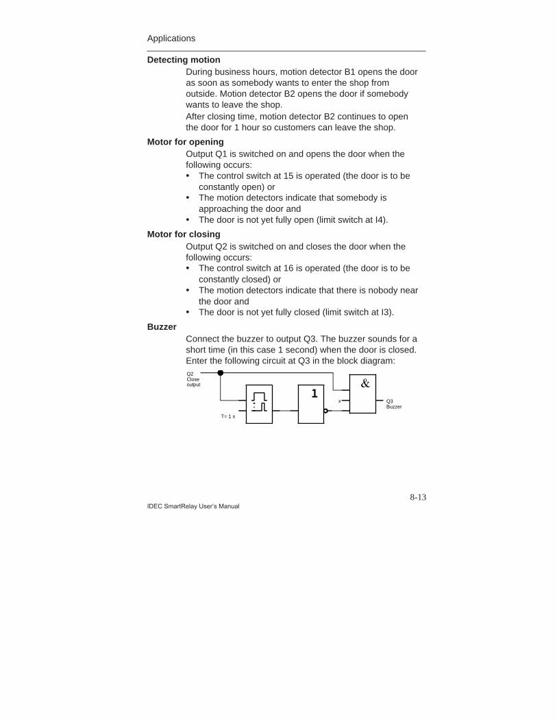
Applications
8-13IDEC SmartRelay User’s Manual
Detecting motionDuring business hours, motion detector B1 opens the dooras soon as somebody wants to enter the shop fromoutside. Motion detector B2 opens the door if somebodywants to leave the shop.After closing time, motion detector B2 continues to openthe door for 1 hour so customers can leave the shop.
Motor for openingOutput Q1 is switched on and opens the door when thefollowing occurs:• The control switch at 15 is operated (the door is to be
constantly open) or• The motion detectors indicate that somebody is
approaching the door and• The door is not yet fully open (limit switch at I4).
Motor for closingOutput Q2 is switched on and closes the door when thefollowing occurs:• The control switch at 16 is operated (the door is to be
constantly closed) or• The motion detectors indicate that there is nobody near
the door and• The door is not yet fully closed (limit switch at I3).
BuzzerConnect the buzzer to output Q3. The buzzer sounds for ashort time (in this case 1 second) when the door is closed.Enter the following circuit at Q3 in the block diagram:
T= 1 s
x Q3Buzzer
Q2Close output
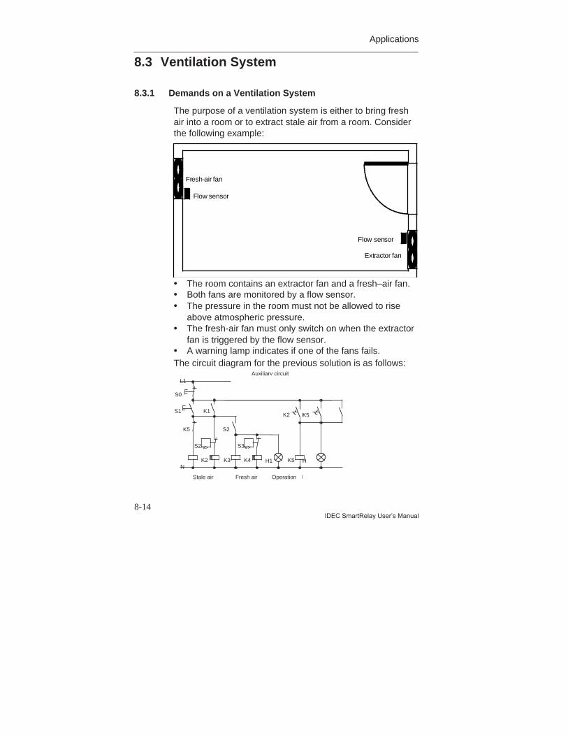
Applications
8-14IDEC SmartRelay User’s Manual
8.3 Ventilation System
8.3.1 Demands on a Ventilation System
The purpose of a ventilation system is either to bring freshair into a room or to extract stale air from a room. Considerthe following example:
Fresh-air fan
Flow sensor
Extractor fan
Flow sensor
• The room contains an extractor fan and a fresh–air fan.• Both fans are monitored by a flow sensor.• The pressure in the room must not be allowed to rise
above atmospheric pressure.• The fresh-air fan must only switch on when the extractor
fan is triggered by the flow sensor.• A warning lamp indicates if one of the fans fails.The circuit diagram for the previous solution is as follows:
K5
K5
S1
Stale air Fresh air
S0
K3K2
Operation
Auxiliary circuitL1
N
S2
K1
v>
S2
H1K4
S3v>
K5
F
H
K2 K
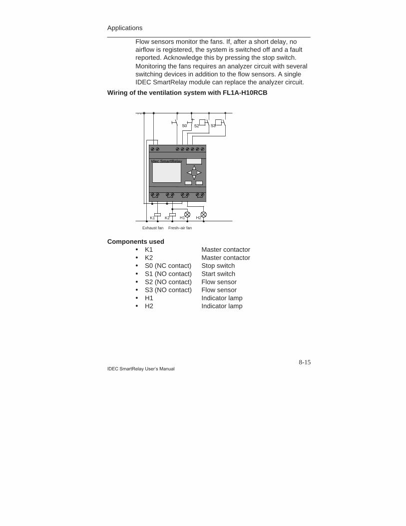
Applications
8-15IDEC SmartRelay User’s Manual
Flow sensors monitor the fans. If, after a short delay, noairflow is registered, the system is switched off and a faultreported. Acknowledge this by pressing the stop switch.Monitoring the fans requires an analyzer circuit with severalswitching devices in addition to the flow sensors. A singleIDEC SmartRelay module can replace the analyzer circuit.
Wiring of the ventilation system with FL1A-H10RCB
Components used• K1 Master contactor• K2 Master contactor• S0 (NC contact) Stop switch• S1 (NO contact) Start switch• S2 (NO contact) Flow sensor• S3 (NO contact) Flow sensor• H1 Indicator lamp• H2 Indicator lamp
L1 N I1 I2 I3 I4 I5 I6
K1 K2
Exhaust fan Fresh–air fan
H1 H2
Idec SmartRelay
L1
S2 S3S0
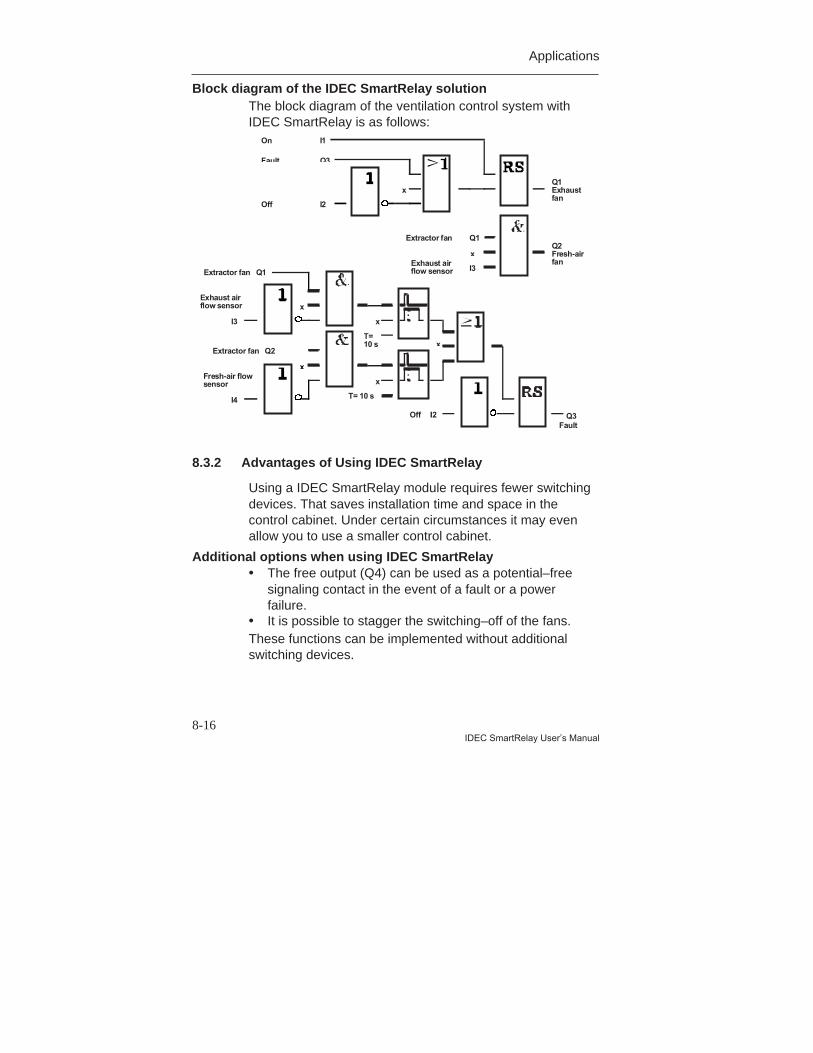
Applications
8-16IDEC SmartRelay User’s Manual
Block diagram of the IDEC SmartRelay solutionThe block diagram of the ventilation control system withIDEC SmartRelay is as follows:
x
I1On
Q3Fault
I2Off
Q1Exhaustfan
I2OffFault
x
T=10 s
x
T= 10 s
x
x
x
I3
Exhaust airflow sensor
I4
Fresh-air flowsensor
Extractor fan Q1
Extractor fan Q2
Q3
Q2Fresh-airfan
Q1Extractor fan
I3Exhaust airflow sensor
x
8.3.2 Advantages of Using IDEC SmartRelay
Using a IDEC SmartRelay module requires fewer switchingdevices. That saves installation time and space in thecontrol cabinet. Under certain circumstances it may evenallow you to use a smaller control cabinet.
Additional options when using IDEC SmartRelay• The free output (Q4) can be used as a potential–free
signaling contact in the event of a fault or a powerfailure.
• It is possible to stagger the switching–off of the fans.These functions can be implemented without additionalswitching devices.
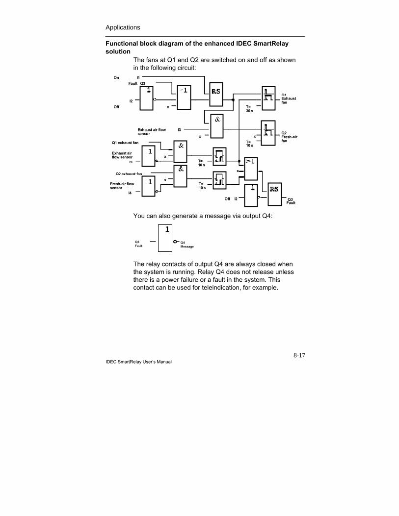
Applications
8-17IDEC SmartRelay User’s Manual
Functional block diagram of the enhanced IDEC SmartRelaysolution
The fans at Q1 and Q2 are switched on and off as shownin the following circuit:
x
T=10 s
T=30 s
Q1Exhaustfan
Q2Fresh-airfan
On
I2
Off
Fault Q3
x
x
I3Exhaust air flowsensor
I2OffFault
T=10 s
T=10 s
x
x
x
I3
Exhaust airflow sensor
I4
Fresh-air flowsensor
Q1 exhaust fan
Q2 exhaust fan
Q3
I1
You can also generate a message via output Q4:
The relay contacts of output Q4 are always closed whenthe system is running. Relay Q4 does not release unlessthere is a power failure or a fault in the system. Thiscontact can be used for teleindication, for example.
Q3Fault
Q4Message
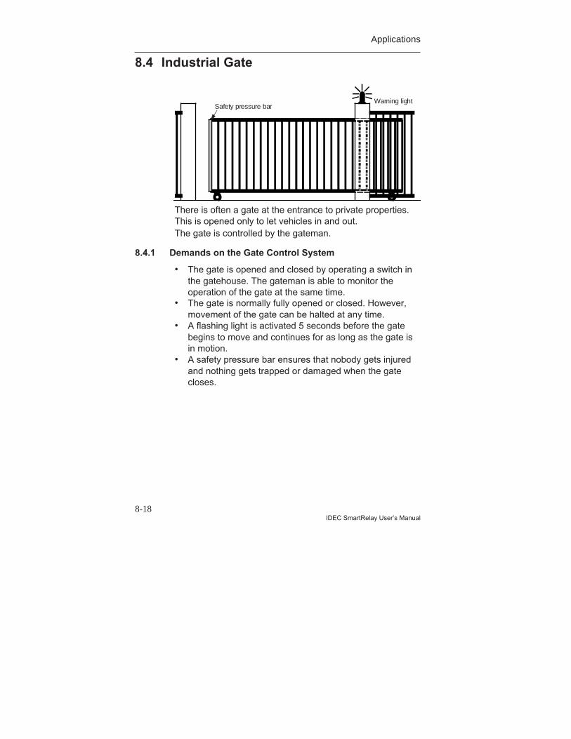
Applications
8-18IDEC SmartRelay User’s Manual
8.4 Industrial Gate
Warning lightSafety pressure bar
There is often a gate at the entrance to private properties.This is opened only to let vehicles in and out.The gate is controlled by the gateman.
8.4.1 Demands on the Gate Control System
• The gate is opened and closed by operating a switch inthe gatehouse. The gateman is able to monitor theoperation of the gate at the same time.
• The gate is normally fully opened or closed. However,movement of the gate can be halted at any time.
• A flashing light is activated 5 seconds before the gatebegins to move and continues for as long as the gate isin motion.
• A safety pressure bar ensures that nobody gets injuredand nothing gets trapped or damaged when the gatecloses.
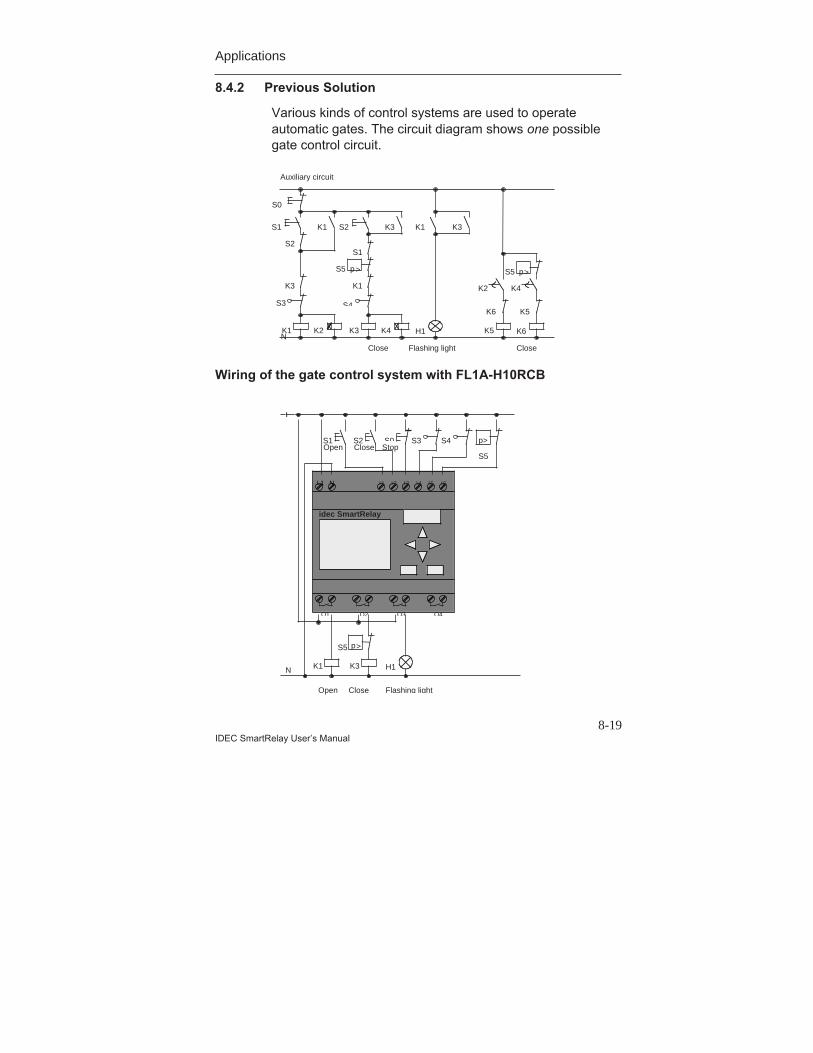
Applications
8-19IDEC SmartRelay User’s Manual
8.4.2 Previous Solution
Various kinds of control systems are used to operateautomatic gates. The circuit diagram shows one possiblegate control circuit.
Wiring of the gate control system with FL1A-H10RCB
K1 K5
K3
S1
S0
K3K2N
K1
H1K4
S5 p>
K6
K1
S2
S2 K3
K2 K4
S5 p>
S1
K3 K1
Close Flashing light
Auxiliary circuit
K6
Close
K5S4S3
L1 N I1 I2 I3 I4 I5 I6
Q1 Q2 Q3 Q4
K1 K3
Open Close
S4S3
L
N
S1 S2 S0
S5
p>
S5 p>
Flashing light
H1
Open Close Stop
idec SmartRelay
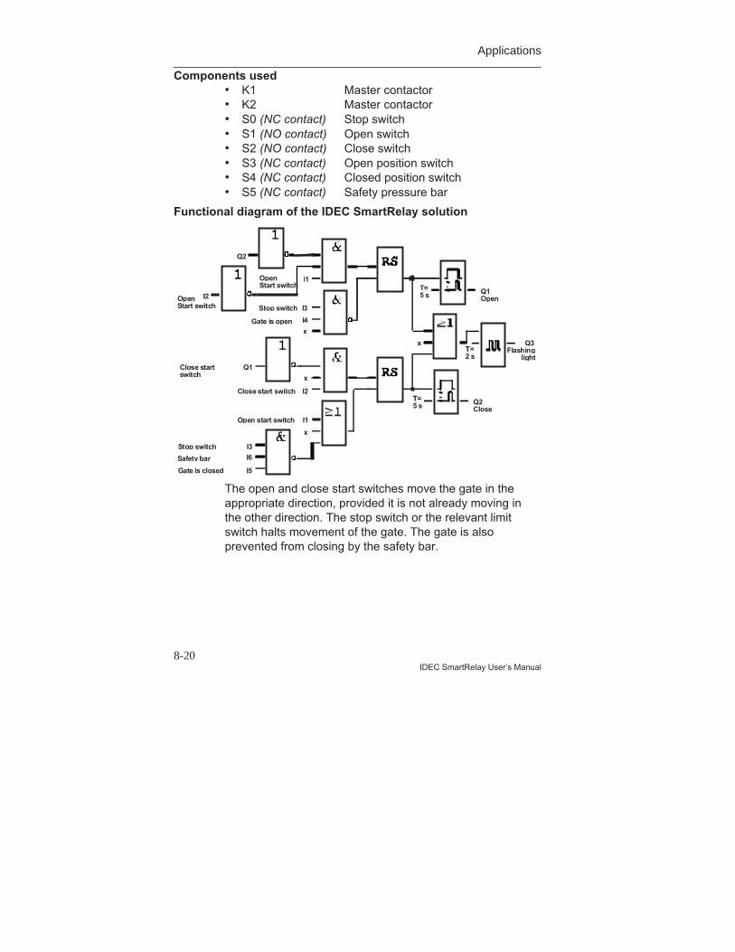
Applications
8-20IDEC SmartRelay User’s Manual
Components used• K1 Master contactor• K2 Master contactor• S0 (NC contact) Stop switch• S1 (NO contact) Open switch• S2 (NO contact) Close switch• S3 (NC contact) Open position switch• S4 (NC contact) Closed position switch• S5 (NC contact) Safety pressure bar
Functional diagram of the IDEC SmartRelay solution
T=5 s
T=5 s
x
x
x
x
Q1Open
Q3Flashing
light
Q2Close
I3
I4
I3
I6
I5
I1
I2
Q2
Q1
Safety bar
Gate is closed
Gate is open
Stop switch
OpenStart switch
Stop switch
Close start switch
T=2 s
I2
I1Open start switch
Close startswitch
OpenStart switch
The open and close start switches move the gate in theappropriate direction, provided it is not already moving inthe other direction. The stop switch or the relevant limitswitch halts movement of the gate. The gate is alsoprevented from closing by the safety bar.
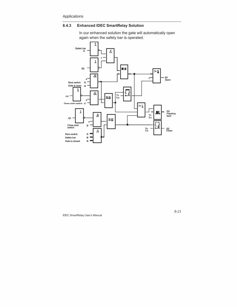
Applications
8-21IDEC SmartRelay User’s Manual
8.4.3 Enhanced IDEC SmartRelay Solution
In our enhanced solution the gate will automatically openagain when the safety bar is operated.
xx
I6Safety bar
x
Q2
I3
I4Gate is openStop switch
x
I1
Q2
Open start switch
T=5 s
Q1Open
T=5 s
x
Q2Close
I3
I6
I5
I2
Q1
Safety bar
Gate is closed
Stop switch
Close startswitch
Q3FlashinglightT=
2 s
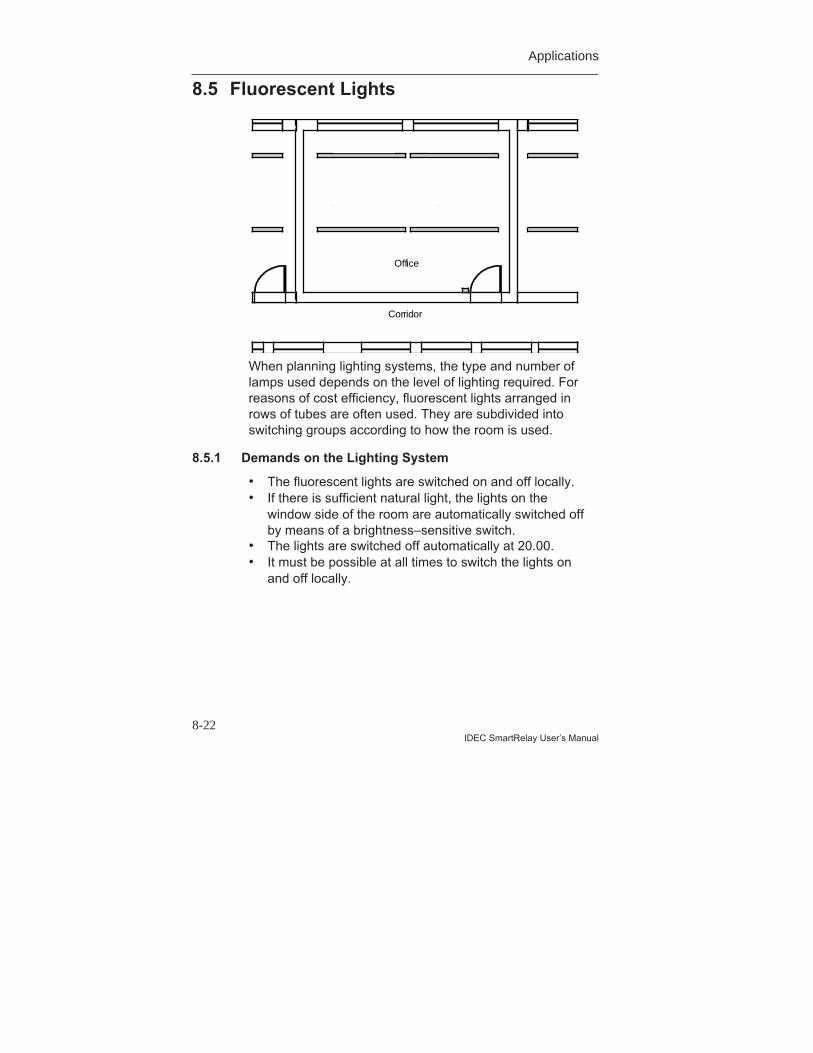
Applications
8-22IDEC SmartRelay User’s Manual
8.5 Fluorescent Lights
Fluorescentluminaire 2
Fluorescentluminaire 1
Fluorescentluminaire 4
Fluorescentluminaire 3
Corridor
Office
When planning lighting systems, the type and number oflamps used depends on the level of lighting required. Forreasons of cost efficiency, fluorescent lights arranged inrows of tubes are often used. They are subdivided intoswitching groups according to how the room is used.
8.5.1 Demands on the Lighting System
• The fluorescent lights are switched on and off locally.• If there is sufficient natural light, the lights on the
window side of the room are automatically switched offby means of a brightness–sensitive switch.
• The lights are switched off automatically at 20.00.• It must be possible at all times to switch the lights on
and off locally.

Applications
8-23IDEC SmartRelay User’s Manual
8.5.2 Previous Solution
The lights are operated by means of a current impulserelay controlled by switches at the door. Independently ofthis, they are reset by the time switch or by thebrightness–sensitive switch via the central off input. Theswitching–off commands must be cut by intervaltime–delay relays so that it is still possible to switch thelights on and off locally after they have been switched offcentrally.Components required:• Switches S1 to S4• Daylight control switch B1• Time switch E1• Interval time–delay relays K1 and K2• Remote–control switches with central off K3 to K6
Disadvantages of the previous solution• To implement the required functions, a large amount of
circuitry is necessary.• The large number of mechanical components means
considerable wear and high maintenance costs can beexpected.
• Functional changes are costly to implement.
L1
N
E1
E1
lx> K6
E5
K5
E4
K4
E3
K3
E2K3 K4 K5 K6
S1 S2 S3 S4
K1 K2
K2K2K1
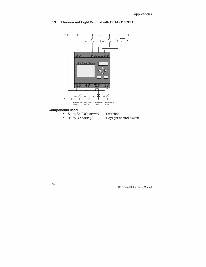
Applications
8-24IDEC SmartRelay User’s Manual
8.5.3 Fluorescent Light Control with FL1A-H10RCB
Components used• S1 to S4 (NO contact) Switches• B1 (NO contact) Daylight control switch
L1 N I1 I2 I3 I4 I5 I6
Q1 Q2 Q3 Q4
L1
NE2 E3 E4
B1
lx<
Fluorescent
lamp 1
E5
Fluorescent
lamp 2
Fluorescent
lamp 3
Fluorescent
lamp
S1 S2 S3 S4
idec SmartRelay
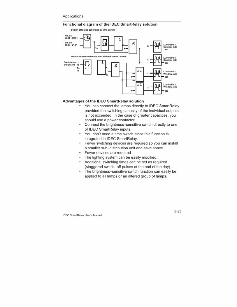
Applications
8-25IDEC SmartRelay User’s Manual
Functional diagram of the IDEC SmartRelay solution
xT=1s
Q2
Mo..Su20:00 - 20.01
Mo..Su21:00 - 21.01
Switch-off pulse generated by time switch
I5
T=1s
Daylight con -trol switch
xI5
Switch-off pulse generated by daylight control switch
I1
I2
I3
I4
x
x
Q1
Q4
Q3
Luminaire 3Corridor side
Luminaire 4Corridor side
Luminaire 1Window side
Luminaire 2Window side
Advantages of the IDEC SmartRelay solution• You can connect the lamps directly to IDEC SmartRelay
provided the switching capacity of the individual outputsis not exceeded. In the case of greater capacities, youshould use a power contactor.
• Connect the brightness–sensitive switch directly to oneof IDEC SmartRelay inputs.
• You don’t need a time switch since this function isintegrated in IDEC SmartRelay.
• Fewer switching devices are required so you can installa smaller sub–distribution unit and save space.
• Fewer devices are required• The lighting system can be easily modified.• Additional switching times can be set as required
(staggered switch–off pulses at the end of the day).• The brightness–sensitive switch function can easily be
applied to all lamps or an altered group of lamps.
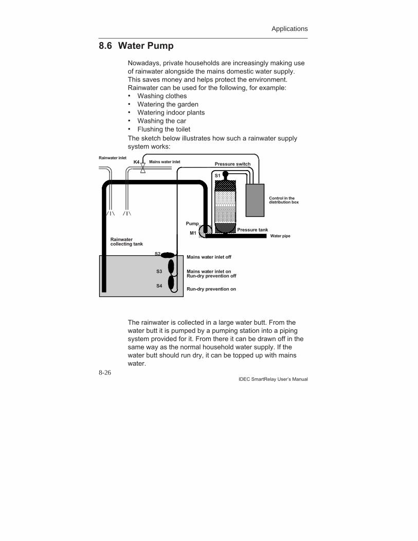
Applications
8-26IDEC SmartRelay User’s Manual
8.6 Water Pump
Nowadays, private households are increasingly making useof rainwater alongside the mains domestic water supply.This saves money and helps protect the environment.Rainwater can be used for the following, for example:• Washing clothes• Watering the garden• Watering indoor plants• Washing the car• Flushing the toiletThe sketch below illustrates how such a rainwater supplysystem works:
The rainwater is collected in a large water butt. From thewater butt it is pumped by a pumping station into a pipingsystem provided for it. From there it can be drawn off in thesame way as the normal household water supply. If thewater butt should run dry, it can be topped up with mainswater.
Run-dry prevention on
Mains water inlet onRun-dry prevention off
Mains water inlet off
PumpPressure tank
Pressure switch
S1
S2
S3
S4
M1Rainwatercollecting tank
Water pipe
Control in thedistribution box
Mains water inletK4Rainwater inlet
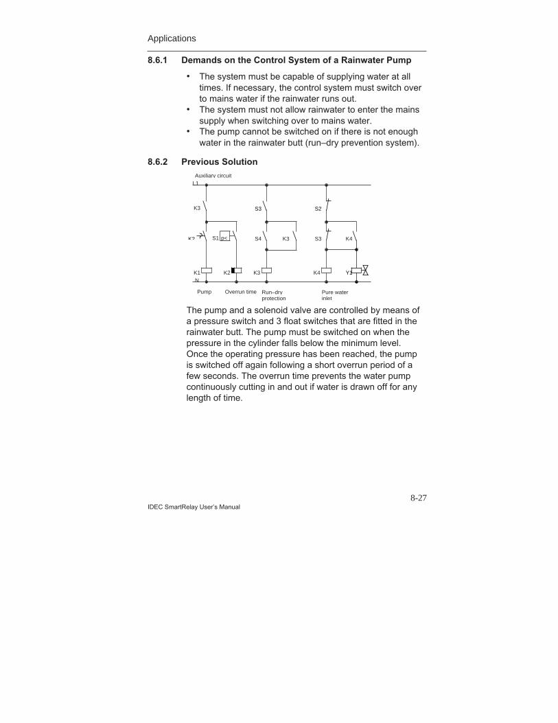
Applications
8-27IDEC SmartRelay User’s Manual
8.6.1 Demands on the Control System of a Rainwater Pump
• The system must be capable of supplying water at alltimes. If necessary, the control system must switch overto mains water if the rainwater runs out.
• The system must not allow rainwater to enter the mainssupply when switching over to mains water.
• The pump cannot be switched on if there is not enoughwater in the rainwater butt (run–dry prevention system).
8.6.2 Previous Solution
The pump and a solenoid valve are controlled by means ofa pressure switch and 3 float switches that are fitted in therainwater butt. The pump must be switched on when thepressure in the cylinder falls below the minimum level.Once the operating pressure has been reached, the pumpis switched off again following a short overrun period of afew seconds. The overrun time prevents the water pumpcontinuously cutting in and out if water is drawn off for anylength of time.
K1 K2
K3
Pump Overrun time
S1
K3
S4 K3
Run–dryprotection
Auxiliary circuitL1
NK4
S3 K4
Pure waterinlet
p<K2
S3 S2
Y1
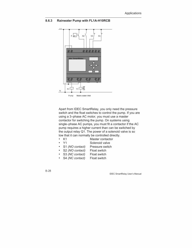
Applications
8-28IDEC SmartRelay User’s Manual
8.6.3 Rainwater Pump with FL1A-H10RCB
Apart from IDEC SmartRelay, you only need the pressureswitch and the float switches to control the pump. If you areusing a 3–phase AC motor, you must use a mastercontactor for switching the pump. On systems usingsingle–phase AC pumps, you must fit a contactor if the ACpump requires a higher current than can be switched bythe output relay Q1. The power of a solenoid valve is solow that it can normally be controlled directly.• K1 Master contactor• Y1 Solenoid valve• S1 (NO contact) Pressure switch• S2 (NO contact) Float switch• S3 (NC contact) Float switch• S4 (NC contact) Float switch
L1 N I1 I2 I3 I4 I5 I
Q1 Q2 Q3 Q
Idec SmartRelay
K1 Y1
Pump
S4S3
L1
N
S S2p<
Mains water inlet
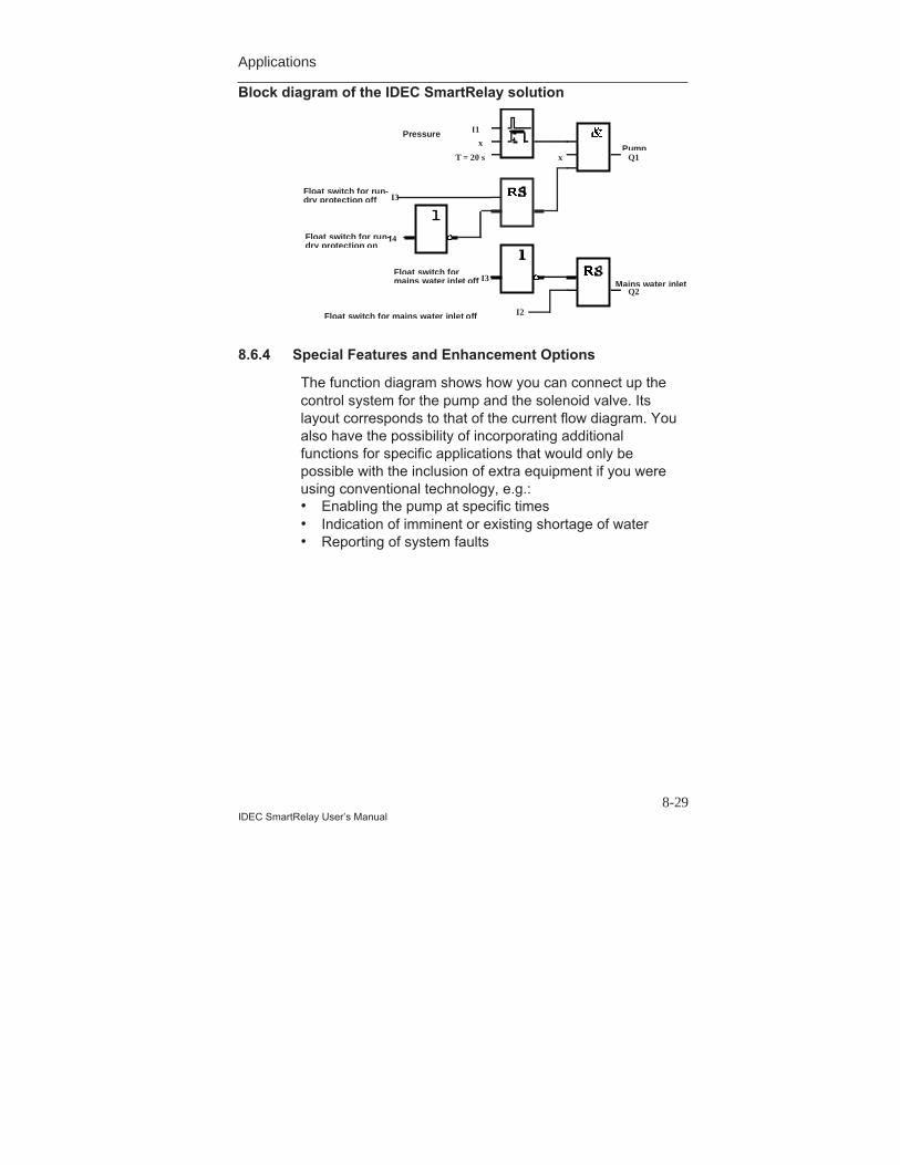
Applications
8-29IDEC SmartRelay User’s Manual
Block diagram of the IDEC SmartRelay solution
I2
Float switch formains water inlet off Mains water inlet
Q2
Float switch for mains water inlet off
I1Pressure
I3
Float switch for run-dry protection on
I4
Float switch for run-dry protection off
x
T = 20 s xPump
Q1
I3
8.6.4 Special Features and Enhancement Options
The function diagram shows how you can connect up thecontrol system for the pump and the solenoid valve. Itslayout corresponds to that of the current flow diagram. Youalso have the possibility of incorporating additionalfunctions for specific applications that would only bepossible with the inclusion of extra equipment if you wereusing conventional technology, e.g.:• Enabling the pump at specific times• Indication of imminent or existing shortage of water• Reporting of system faults
Applications
8-30IDEC SmartRelay User’s Manual
8.7 Further Potential Applications
The following are some of the IDEC SmartRelayapplications:• Watering greenhouse plants• Control of conveyor systems• Control of a bending machine• Shop window lighting• Bell system (e.g. in a school)• Parking lot surveillance• Exterior lighting• Control system for shutters• Interior and exterior lighting for an apartment block• Control system for a cream stirrer• Sports hall lighting• Equal distribution of 3 loads• Sequence control system for cable–welding machines
with large cross–sections• Step switch (e.g. for fans)• Boiler sequence control• Control system for several pump sets with centralized
operation• Cutting device (e.g. for detonating fuses)• Monitoring length of use (e.g. in solar energy system)• Intelligent foot buttons (e.g. to select speeds)• Control of an elevating platform• Impregnation of textiles - heating and conveyor control
system• Silo–filling systemAnd many more.You can also find descriptions and the relevant circuitdiagrams of the applications on the Internet. You can readthese *.pdf files with Adobe Acrobat Reader. If you haveinstalled the WindLGC programming software on your PC,you can download the relevant circuit diagrams, adaptthem to your requirements, transfer them into IDECSmartRelay via the PC cable and implement them.
Applications
8-31IDEC SmartRelay User’s Manual
Advantages of using IDEC SmartRelay• Replace a number of auxiliary switching devices with
the integrated functions of IDEC SmartRelay.• Save yourself wiring and installation work (because the
wiring is done in IDEC SmartRelay).• Reduce the space required for components in the
control cabinet/distribution box. You may be able to usea smaller control cabinet/distribution box.
• Add or change functions subsequently without having toinstall an additional switching device or change thewiring.
• Provide your customers with additional functions fortheir domestic or building installation. Here are someexamples:- Home security: You can program IDEC SmartRelay
to switch a lamp on regularly or open and close yourshutters while you are on holiday.
- Heating system: You can program IDEC SmartRelayto run the circulation pump only when water or heatis really required.
- Cooling systems: You can program IDECSmartRelay to thaw your cooling systemsautomatically on a regular basis to save energycosts.
- You can illuminate aquaria and terraria automaticallyon a time–dependent basis.
You can also:• Use commercially available switches and buttons, which
makes it easy to integrate in the installation.• Connect IDEC SmartRelay directly to your domestic
installation due to its integrated power supply.

Applications
8-32IDEC SmartRelay User’s Manual
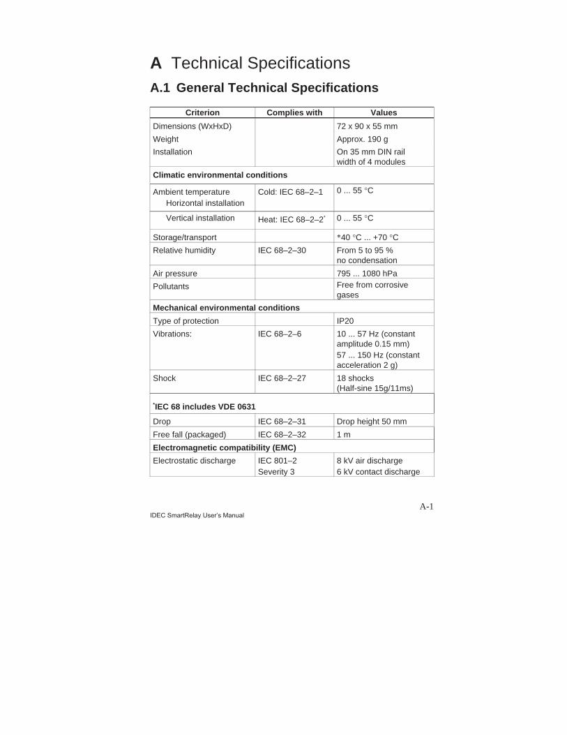
A-1IDEC SmartRelay User’s Manual
A Technical SpecificationsA.1 General Technical Specifications
Criterion Complies with Values
Dimensions (WxHxD) 72 x 90 x 55 mm
Weight Approx. 190 g
Installation On 35 mm DIN railwidth of 4 modules
Climatic environmental conditions
Ambient temperatureHorizontal installation
Cold: IEC 68–2–1 0 ... 55 °C
Vertical installation Heat: IEC 68–2–2* 0 ... 55 °C
Storage/transport *40 °C ... +70 °C
Relative humidity IEC 68–2–30 From 5 to 95 %no condensation
Air pressure 795 ... 1080 hPa
Pollutants Free from corrosivegases
Mechanical environmental conditions
Type of protection IP20
Vibrations: IEC 68–2–6 10 ... 57 Hz (constantamplitude 0.15 mm)57 ... 150 Hz (constantacceleration 2 g)
Shock IEC 68–2–27 18 shocks(Half-sine 15g/11ms)
*IEC 68 includes VDE 0631
Drop IEC 68–2–31 Drop height 50 mm
Free fall (packaged) IEC 68–2–32 1 m
Electromagnetic compatibility (EMC)
Electrostatic discharge IEC 801–2Severity 3
8 kV air discharge6 kV contact discharge
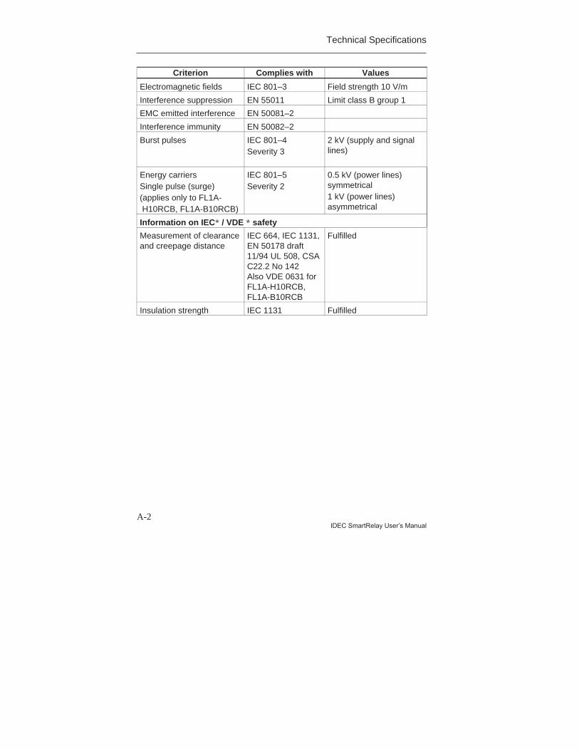
Technical Specifications
A-2IDEC SmartRelay User’s Manual
Criterion Complies with Values
Electromagnetic fields IEC 801–3 Field strength 10 V/m
Interference suppression EN 55011 Limit class B group 1
EMC emitted interference EN 50081–2
Interference immunity EN 50082–2
Burst pulses IEC 801–4Severity 3
2 kV (supply and signallines)
Energy carriersSingle pulse (surge)(applies only to FL1A- H10RCB, FL1A-B10RCB)
IEC 801–5Severity 2
0.5 kV (power lines)symmetrical1 kV (power lines)asymmetrical
Information on IEC* / VDE * safety
Measurement of clearanceand creepage distance
IEC 664, IEC 1131,EN 50178 draft11/94 UL 508, CSAC22.2 No 142Also VDE 0631 forFL1A-H10RCB,FL1A-B10RCB
Fulfilled
Insulation strength IEC 1131 Fulfilled
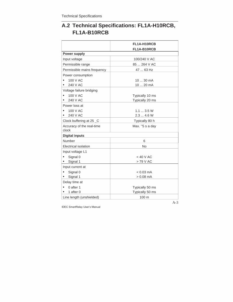
Technical Specifications
A-3IDEC SmartRelay User’s Manual
A.2 Technical Specifications: FL1A-H10RCB,FL1A-B10RCB
FL1A-H10RCB
FL1A-B10RCBPower supply
Input voltage 100/240 V AC
Permissible range 85 ... 264 V AC
Permissible mains frequency 47 ... 63 Hz
Power consumption
• 100 V AC• 240 V AC
10 ... 30 mA10 ... 20 mA
Voltage failure bridging
• 100 V AC• 240 V AC
Typically 10 msTypically 20 ms
Power loss at
• 100 V AC• 240 V AC
1.1 ... 3.5 W2.3 ... 4.6 W
Clock buffering at 25 _C Typically 80 h
Accuracy of the real-timeclock
Max. ”5 s a day
Digital inputs
Number 6
Electrical isolation No
Input voltage L1
• Signal 0• Signal 1
< 40 V AC> 79 V AC
Input current at
• Signal 0• Signal 1
< 0.03 mA> 0.08 mA
Delay time at
• 0 after 1• 1 after 0
Typically 50 msTypically 50 ms
Line length (unshielded) 100 m
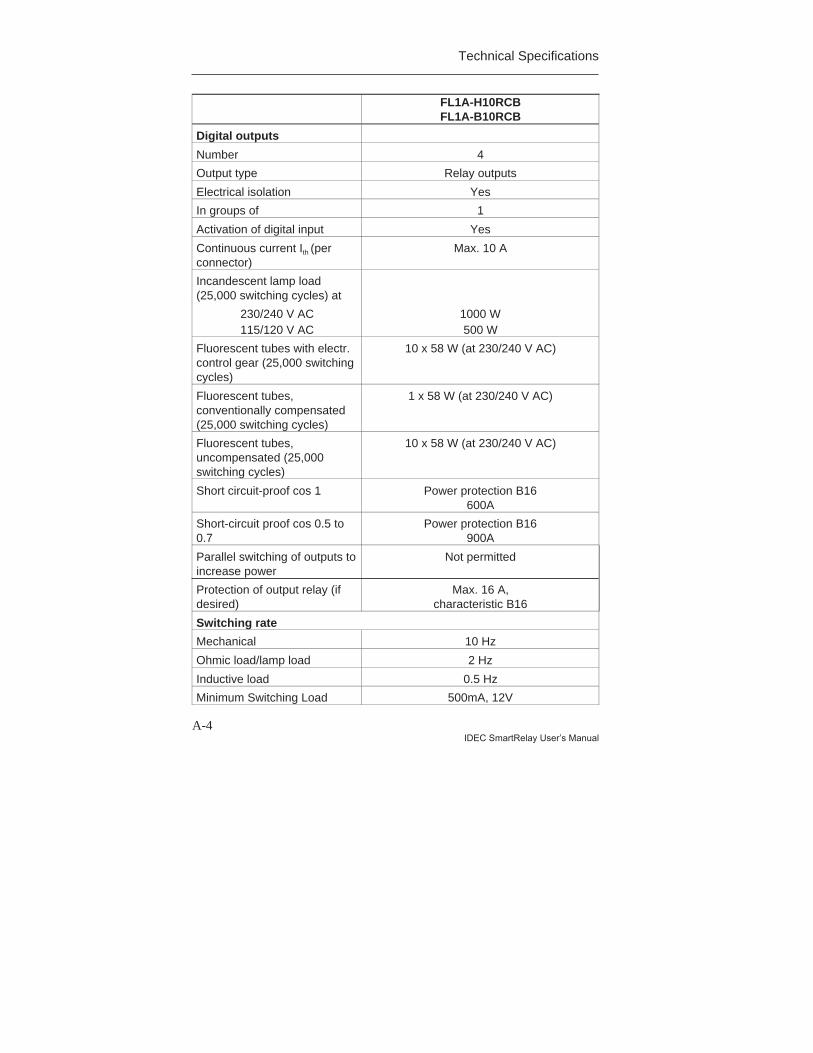
Technical Specifications
A-4IDEC SmartRelay User’s Manual
FL1A-H10RCBFL1A-B10RCB
Digital outputs
Number 4
Output type Relay outputs
Electrical isolation Yes
In groups of 1
Activation of digital input Yes
Continuous current Ith (perconnector)
Max. 10 A
Incandescent lamp load(25,000 switching cycles) at
230/240 V AC115/120 V AC
1000 W500 W
Fluorescent tubes with electr.control gear (25,000 switchingcycles)
10 x 58 W (at 230/240 V AC)
Fluorescent tubes,conventionally compensated(25,000 switching cycles)
1 x 58 W (at 230/240 V AC)
Fluorescent tubes,uncompensated (25,000switching cycles)
10 x 58 W (at 230/240 V AC)
Short circuit-proof cos 1 Power protection B16600A
Short-circuit proof cos 0.5 to0.7
Power protection B16900A
Parallel switching of outputs toincrease power
Not permitted
Protection of output relay (ifdesired)
Max. 16 A,characteristic B16
Switching rate
Mechanical 10 Hz
Ohmic load/lamp load 2 Hz
Inductive load 0.5 Hz
Minimum Switching Load 500mA, 12V

Technical Specifications
A-5IDEC SmartRelay User’s Manual
FL1A-H10RCB
FL1A-B10RCB
Initial Contact Resistance 100mOhm at 1A at 24V
Mechanical Life 10Million
(No Load: 10Hz)
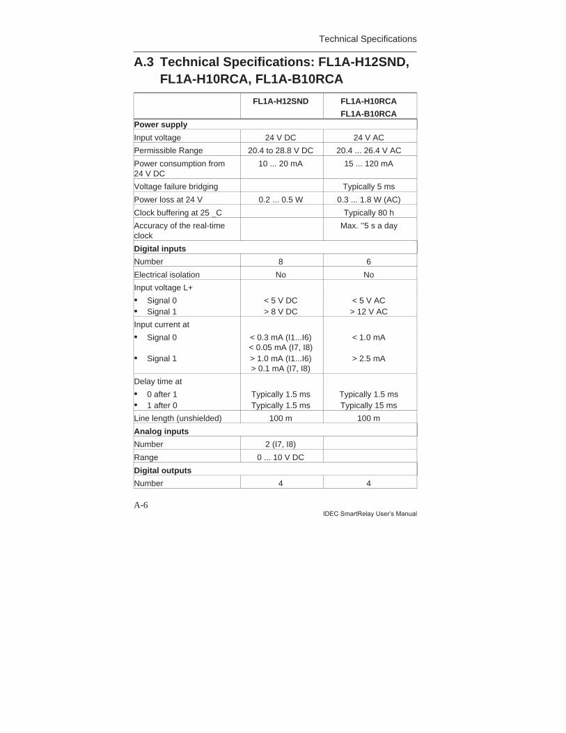
Technical Specifications
A-6IDEC SmartRelay User’s Manual
A.3 Technical Specifications: FL1A-H12SND,FL1A-H10RCA, FL1A-B10RCA
FL1A-H12SND FL1A-H10RCA
FL1A-B10RCAPower supply
Input voltage 24 V DC 24 V AC
Permissible Range 20.4 to 28.8 V DC 20.4 ... 26.4 V AC
Power consumption from24 V DC
10 ... 20 mA 15 ... 120 mA
Voltage failure bridging Typically 5 ms
Power loss at 24 V 0.2 ... 0.5 W 0.3 ... 1.8 W (AC)
Clock buffering at 25 _C Typically 80 h
Accuracy of the real-timeclock
Max. ”5 s a day
Digital inputs
Number 8 6
Electrical isolation No No
Input voltage L+
• Signal 0• Signal 1
< 5 V DC> 8 V DC
< 5 V AC> 12 V AC
Input current at
• Signal 0
• Signal 1
< 0.3 mA (I1...I6)< 0.05 mA (I7, I8)> 1.0 mA (I1...I6)> 0.1 mA (I7, I8)
< 1.0 mA
> 2.5 mA
Delay time at
• 0 after 1• 1 after 0
Typically 1.5 msTypically 1.5 ms
Typically 1.5 msTypically 15 ms
Line length (unshielded) 100 m 100 m
Analog inputs
Number 2 (I7, I8)
Range 0 ... 10 V DC
Digital outputs
Number 4 4
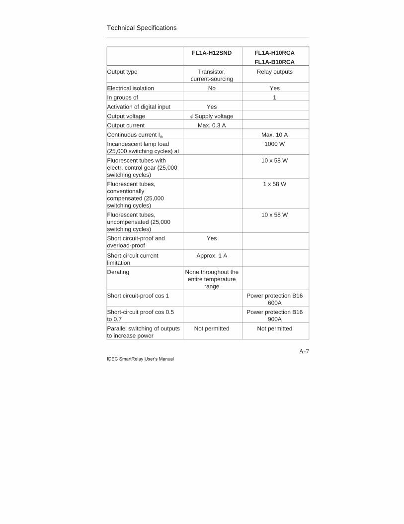
Technical Specifications
A-7IDEC SmartRelay User’s Manual
FL1A-H12SND FL1A-H10RCA
FL1A-B10RCA
Output type Transistor,current-sourcing
Relay outputs
Electrical isolation No Yes
In groups of 1
Activation of digital input Yes
Output voltage ¢ Supply voltage
Output current Max. 0.3 A
Continuous current Ith Max. 10 A
Incandescent lamp load(25,000 switching cycles) at
1000 W
Fluorescent tubes withelectr. control gear (25,000switching cycles)
10 x 58 W
Fluorescent tubes,conventionallycompensated (25,000switching cycles)
1 x 58 W
Fluorescent tubes,uncompensated (25,000switching cycles)
10 x 58 W
Short circuit-proof andoverload-proof
Yes
Short-circuit currentlimitation
Approx. 1 A
Derating None throughout theentire temperature
range
Short circuit-proof cos 1 Power protection B16600A
Short-circuit proof cos 0.5to 0.7
Power protection B16900A
Parallel switching of outputsto increase power
Not permitted Not permitted
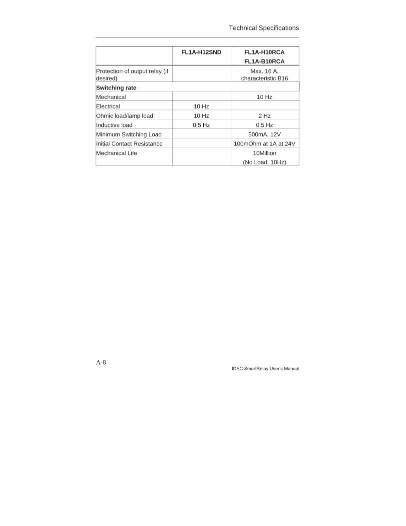
Technical Specifications
A-8IDEC SmartRelay User’s Manual
FL1A-H12SND FL1A-H10RCA
FL1A-B10RCA
Protection of output relay (ifdesired)
Max. 16 A,characteristic B16
Switching rate
Mechanical 10 Hz
Electrical 10 Hz
Ohmic load/lamp load 10 Hz 2 Hz
Inductive load 0.5 Hz 0.5 Hz
Minimum Switching Load 500mA, 12V
Initial Contact Resistance 100mOhm at 1A at 24V
Mechanical Life 10Million
(No Load: 10Hz)
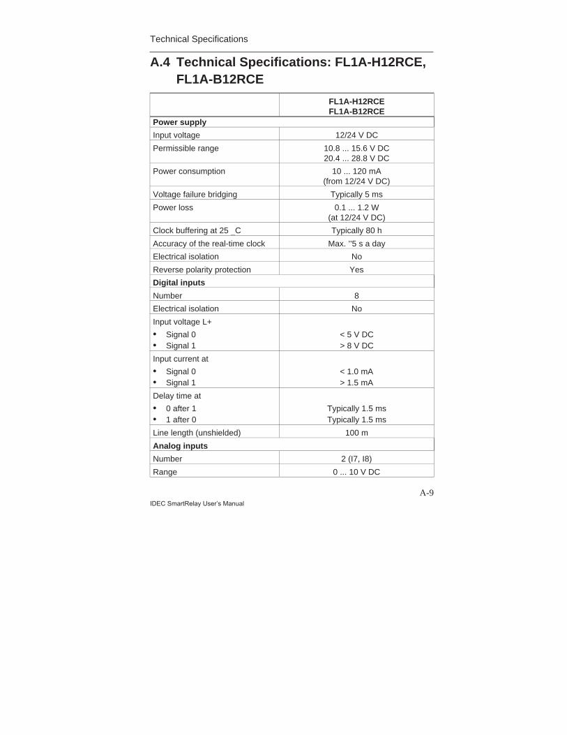
Technical Specifications
A-9IDEC SmartRelay User’s Manual
A.4 Technical Specifications: FL1A-H12RCE,FL1A-B12RCE
FL1A-H12RCEFL1A-B12RCE
Power supply
Input voltage 12/24 V DC
Permissible range 10.8 ... 15.6 V DC20.4 ... 28.8 V DC
Power consumption 10 ... 120 mA(from 12/24 V DC)
Voltage failure bridging Typically 5 ms
Power loss 0.1 ... 1.2 W(at 12/24 V DC)
Clock buffering at 25 _C Typically 80 h
Accuracy of the real-time clock Max. ”5 s a day
Electrical isolation No
Reverse polarity protection Yes
Digital inputs
Number 8
Electrical isolation No
Input voltage L+
• Signal 0• Signal 1
< 5 V DC> 8 V DC
Input current at
• Signal 0• Signal 1
< 1.0 mA> 1.5 mA
Delay time at
• 0 after 1• 1 after 0
Typically 1.5 msTypically 1.5 ms
Line length (unshielded) 100 m
Analog inputs
Number 2 (I7, I8)
Range 0 ... 10 V DC
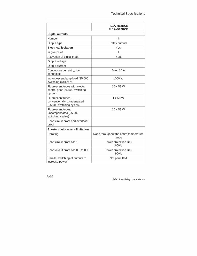
Technical Specifications
A-10IDEC SmartRelay User’s Manual
FL1A-H12RCEFL1A-B12RCE
Digital outputs
Number 4
Output type Relay outputs
Electrical isolation Yes
In groups of 1
Activation of digital input Yes
Output voltage
Output current
Continuous current Ith (perconnector)
Max. 10 A
Incandescent lamp load (25,000switching cycles) at
1000 W
Fluorescent tubes with electr.control gear (25,000 switchingcycles)
10 x 58 W
Fluorescent tubes,conventionally compensated(25,000 switching cycles)
1 x 58 W
Fluorescent tubes,uncompensated (25,000switching cycles)
10 x 58 W
Short circuit-proof and overload-proof
Short-circuit current limitation
Derating None throughout the entire temperaturerange
Short circuit-proof cos 1 Power protection B16600A
Short-circuit proof cos 0.5 to 0.7 Power protection B16900A
Parallel switching of outputs toincrease power
Not permitted

Technical Specifications
A-11IDEC SmartRelay User’s Manual
FL1A-H12RCEFL1A-B12RCE
Protection of output relay (ifdesired)
Max. 16 A,characteristic B16
Switching rate
Mechanical 10 Hz
Electrical
Ohmic load/lamp load 2 Hz
Inductive load 0.5 Hz
Minimum Switching Load 500mA, 12V
Initial Contact Resistance 100mOhm at 1A at 24V
Mechanical Life 10Million
(No Load: 10Hz)
Switching capacity and service life of the relay outputs
Switching cycles/million
Switched current/A
0.1
0.2
0.3
0.40.5
321
0.6
0.7
0.8
0.91.0
Maximum 2 AMaximum 3 AMaximum 3 A
12/24 V AC/DC115/120 V AC230/240 V AC
Ohmic load
Figure A Switching capacity and service life of the contacts at ohmic load(heating)
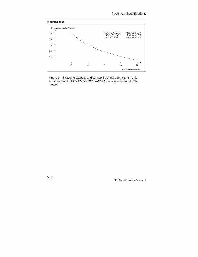
Technical Specifications
A-12IDEC SmartRelay User’s Manual
Inductive load
Switching cycles/million
Switched current/A
0.1
0.2
0.3
0.4
0.5
2 4 6 8 10
Maximum 10 AMaximum 10 AMaximum 10 A
12/24 V AC/DC115/120 V AC230/240 V AC
Figure B Switching capacity and service life of the contacts at highlyinductive load to IEC 947–5–1 DC13/AC15 (contactors, solenoid coils,motors)
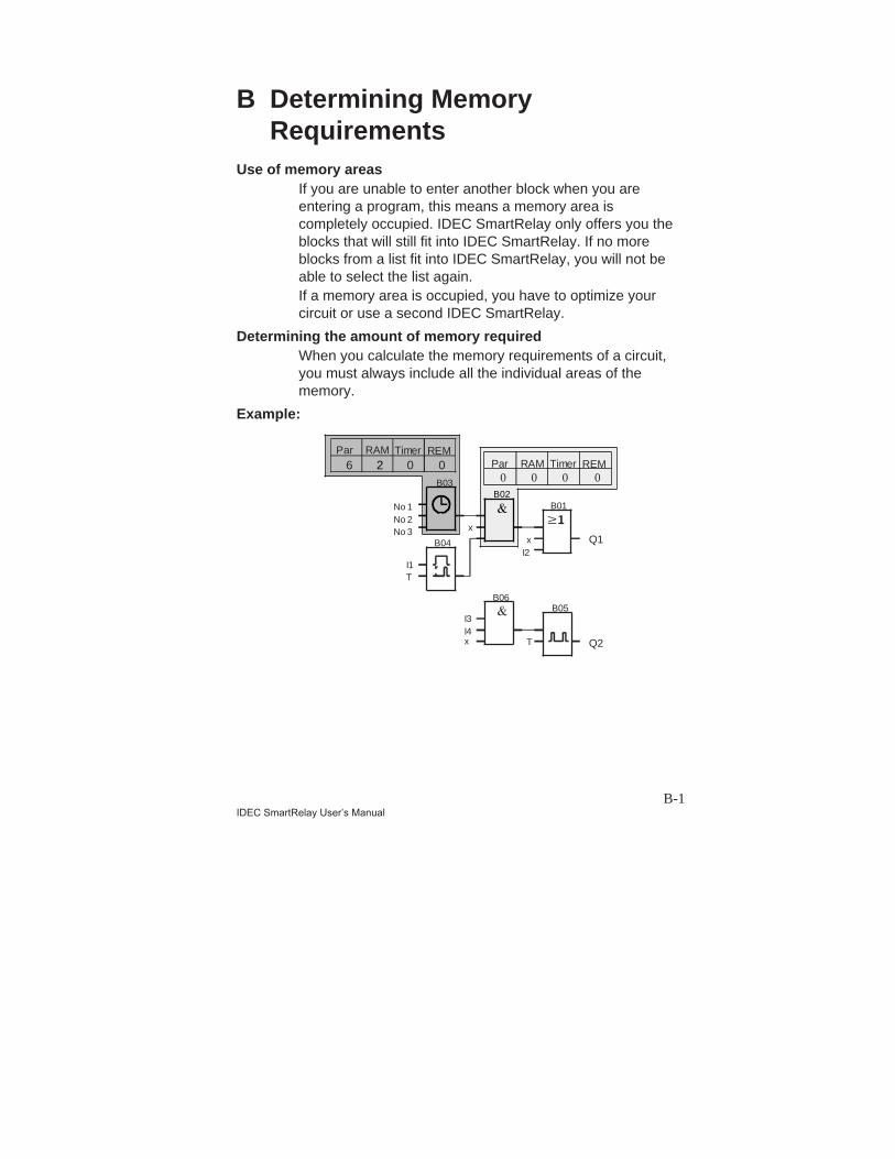
B-1IDEC SmartRelay User’s Manual
B Determining MemoryRequirements
Use of memory areasIf you are unable to enter another block when you areentering a program, this means a memory area iscompletely occupied. IDEC SmartRelay only offers you theblocks that will still fit into IDEC SmartRelay. If no moreblocks from a list fit into IDEC SmartRelay, you will not beable to select the list again.If a memory area is occupied, you have to optimize yourcircuit or use a second IDEC SmartRelay.
Determining the amount of memory requiredWhen you calculate the memory requirements of a circuit,you must always include all the individual areas of thememory.
Example:
B03
6 002
B02
0 000
B06B05
Q1xI2
B01
x
B04
No 1No 2No 3
I1T
T Q2
I3I4x
Par RAM REMTimerPar RAM REMTimer
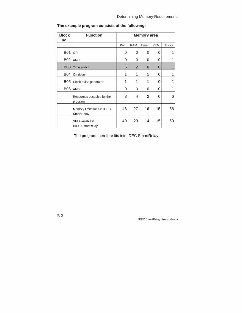
Determining Memory Requirements
B-2IDEC SmartRelay User’s Manual
The example program consists of the following:
Blockno.
Function Memory area
Par RAM Timer REM Blocks
B01 OR 0 0 0 0 1
B02 AND 0 0 0 0 1
B03 Time switch 6 2 0 0 1
B04 On delay 1 1 1 0 1
B05 Clock pulse generator 1 1 1 0 1
B06 AND 0 0 0 0 1
Resources occupied by the
program
8 4 2 0 6
Memory limitations in IDEC
SmartRelay
48 27 16 15 56
Still available in
IDEC SmartRelay
40 23 14 15 50
The program therefore fits into IDEC SmartRelay.

C-1IDEC SmartRelay User’s Manual
C Determining the Cycle TimeThe program cycle is the complete execution of theprogram, primarily the reading in of the inputs, theprocessing of the program and the subsequent reading outof the outputs. The cycle time is the time required toexecute a program once in full.The time required for a program cycle can be determinedusing a short test program. The test program is created inIDEC SmartRelay and produces a value during processingin parameterization mode from which the current cycle timecan be calculated.
Test program1. Create the test program by linking an output or marker
to a threshold switch and by switching a clock pulsegenerator at its input, which is switched on by a hisignal.
2. Parameterize the two blocks as shown below. A clockpulse is generated in each program cycle based on thecycle time of 0 seconds. The time interval of thethreshold switch is set to 2 seconds.
Hi
Par Qx
T
B01Output Q
or
Memory
marker M
B02:TT =00.00s+
B01:ParSW =1000+SW =0000G_T=02.00s
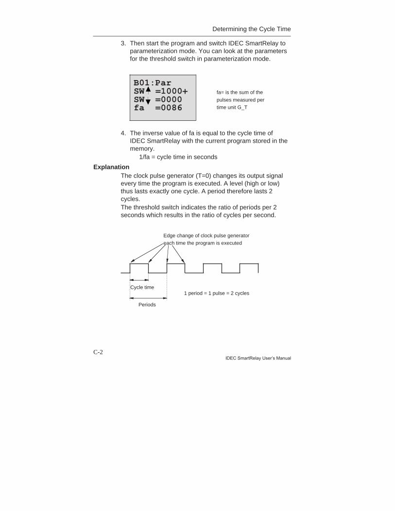
Determining the Cycle Time
C-2IDEC SmartRelay User’s Manual
3. Then start the program and switch IDEC SmartRelay toparameterization mode. You can look at the parametersfor the threshold switch in parameterization mode.
4. The inverse value of fa is equal to the cycle time ofIDEC SmartRelay with the current program stored in thememory.
1/fa = cycle time in seconds
ExplanationThe clock pulse generator (T=0) changes its output signalevery time the program is executed. A level (high or low)thus lasts exactly one cycle. A period therefore lasts 2cycles.The threshold switch indicates the ratio of periods per 2seconds which results in the ratio of cycles per second.
Edge change of clock pulse generator
each time the program is executed
Cycle time
Periods
1 period = 1 pulse = 2 cycles
B01:ParSW =1000+SW =0000fa =0086
fa= is the sum of the
pulses measured per
time unit G_T

D-1IDEC SmartRelay User’s Manual
D IDEC SmartRelay Without aDisplay
The FL1A-B12RCE, FL1A-B10RCA and FL1A-B10RCBvariants were developed without a display because somespecial applications don’t need operating units such askeypads and a display during operation.
I4 I5 I6
Q1 Q2 Q3 Q4
I1 I2 I3 1 L N
RUN/STOP
SmartRelay Output 4 x
l /10A
Idec
Less is definitely more!The advantages for you:• More cost–efficient than models with a display.• Requires less space in the cabinet than conventional
hardware.• More flexible and less costly than separate hardware
units.• Advantageous for applications in which two or three
conventional switching devices can be replaced.• Very easy to use.• Cannot be used by unauthorized persons.• Compatible with FL1A-H12SND, FL1A-H12RCE, FL1A-
H10RCA and FL1A-H10RCB.
idec SmartRelay
IDEC SmartRelay without a Display
D-2IDEC SmartRelay User’s Manual
Programming without an operating unitThere are two ways to program IDEC SmartRelay without adisplay:• Create a program with WindLGC on the PC and transfer
the program to IDEC SmartRelay• Transfer the program from a IDEC SmartRelay memory
cartridge to your IDEC SmartRelay without a display.
Operating characteristicsOnce the power supply has been connected, IDECSmartRelay is ready for operation. You can switch off IDECSmartRelay without a display by disconnecting the powersupply, for example by removing the plug.You can’t use a key combination to set up FL1A-B12RCE,FL1A-B10RCA and FL1A-B10RCB for data transfer, andprograms cannot be stopped or started using keys. FL1A-B12RCE, FL1A-B10RCA and FL1A-B10RCB thereforehave modified startup characteristics.
Startup characteristicsIf a IDEC SmartRelay memory cartridge is inserted, aprogram stored there will be copied to the deviceimmediately after IDEC SmartRelay has been switched on,thus overwriting an existing program.If a PC-CABLE is inserted, IDEC SmartRelay automaticallygoes into PC ´ IDEC SmartRelay mode when it is switched on.Using the PC software WindLGC you can read the programsfrom IDEC SmartRelay or store them on IDEC SmartRelay.If there is already a valid program in the memory cartridge,IDEC SmartRelay will automatically transfer from STOP toRUN after power has been switched on.
Operating status indicatorOperating statuses, such as Power On, RUN and STOPare indicated by an LED on the front hood.• Red LED: PowerOn/STOP• Green LED: PowerOn/RUNAfter the power supply has been switched on andwhenever IDEC SmartRelay is not in RUN mode, the redLED comes on. When IDEC SmartRelay is in RUN mode,the green LED comes on.
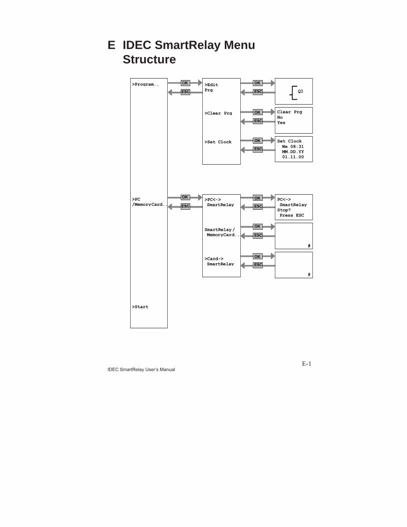
E-1IDEC SmartRelay User’s Manual
E IDEC SmartRelay MenuStructure
#
#
Set ClockWe 08:31MM.DD.YY01.11.00
Clear PrgNoYes
>Program..
>PC/MemoryCard..
>Start
>Card->SmartRelay
SmartRelay/MemoryCard..
>PC<->SmartRelay
>Set Clock
>Clear Prg
>EditPrg Q1
PC<->SmartRelayStop?Press ESC
OK OK
OK
OK
OK
OK
OK
OK
ESC ESC
ESC
ESC
ESC
ESC
ESC
ESC

IDEC SmartRelay Menu Structure
E-2IDEC SmartRelay User’s Manual
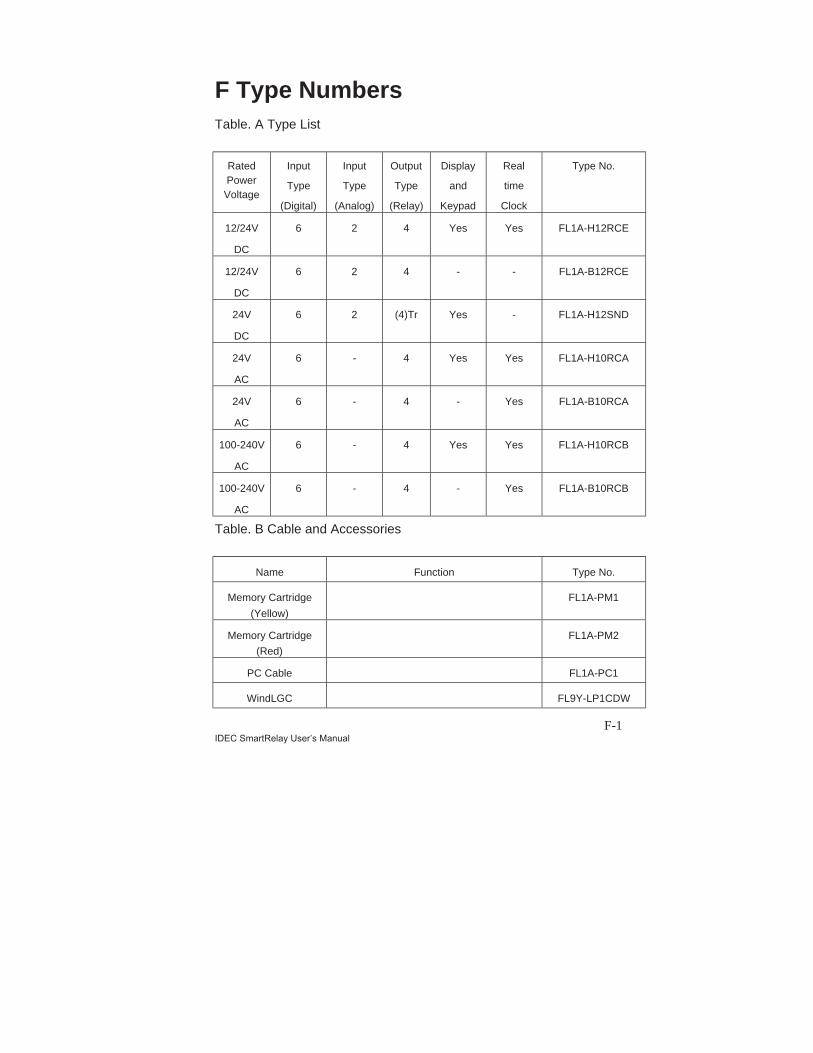
F-1IDEC SmartRelay User’s Manual
F Type NumbersTable. A Type List
RatedPowerVoltage
Input
Type
(Digital)
Input
Type
(Analog)
Output
Type
(Relay)
Display
and
Keypad
Real
time
Clock
Type No.
12/24V
DC
6 2 4 Yes Yes FL1A-H12RCE
12/24V
DC
6 2 4 - - FL1A-B12RCE
24V
DC
6 2 (4)Tr Yes - FL1A-H12SND
24V
AC
6 - 4 Yes Yes FL1A-H10RCA
24V
AC
6 - 4 - Yes FL1A-B10RCA
100-240V
AC
6 - 4 Yes Yes FL1A-H10RCB
100-240V
AC
6 - 4 - Yes FL1A-B10RCB
Table. B Cable and Accessories
Name Function Type No.
Memory Cartridge
(Yellow)
FL1A-PM1
Memory Cartridge
(Red)
FL1A-PM2
PC Cable FL1A-PC1
WindLGC FL9Y-LP1CDW

Type Numbers
F-2IDEC SmartRelay User’s Manual
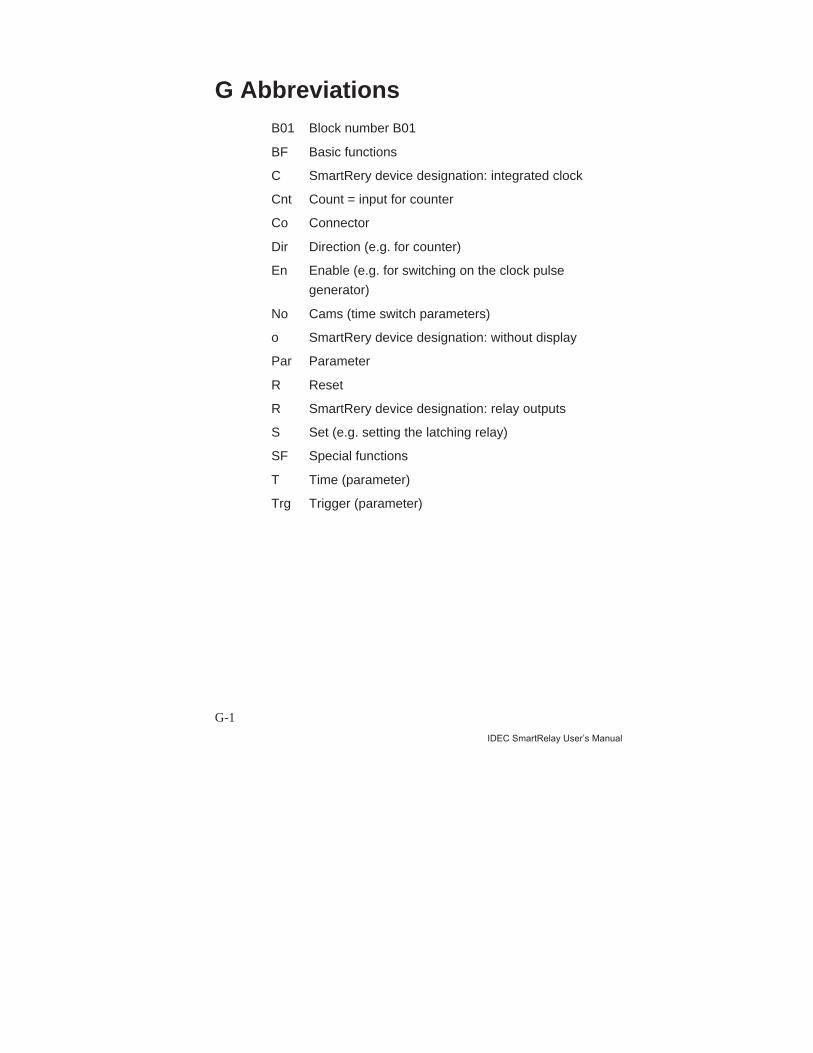
G-1
IDEC SmartRelay User’s Manual
G AbbreviationsB01 Block number B01
BF Basic functions
C SmartRery device designation: integrated clock
Cnt Count = input for counter
Co Connector
Dir Direction (e.g. for counter)
En Enable (e.g. for switching on the clock pulse
generator)
No Cams (time switch parameters)
o SmartRery device designation: without display
Par Parameter
R Reset
R SmartRery device designation: relay outputs
S Set (e.g. setting the latching relay)
SF Special functions
T Time (parameter)
Trg Trigger (parameter)

Abbreviations
G-2IDEC SmartRelay User’s Manual