Embed Size (px)
Citation preview
IBM FlashSystem A9000RModels 9835-415 and 9837-415
Deployment Guide
GC27-8565-03
IBM

NoteBefore using this information and the product it supports, read the information in “Safety and environmental notices” onpage xi and “Notices” on page 91.
Edition Notice
Publication number: GC27-8565-03.
This publication applies to IBM FlashSystem A9000R, replacing GC27-8565-02, and shall remain applicable to allproduct releases and modifications until replaced by a newer publication.
© Copyright IBM Corporation 2016, 2017.US Government Users Restricted Rights – Use, duplication or disclosure restricted by GSA ADP Schedule Contractwith IBM Corp.
Contents
Figures . . . . . . . . . . . . . . . . . . . . . . . . . . . . . . . . . . . vii
Tables . . . . . . . . . . . . . . . . . . . . . . . . . . . . . . . . . . . . ix
Safety and environmental notices . . . . . . . . . . . . . . . . . . . . . . . . xiSafety notices and labels . . . . . . . . . . . . . . . . . . . . . . . . . . . . . . . xiSpecial caution and safety notices . . . . . . . . . . . . . . . . . . . . . . . . . . . . xii
Laser safety . . . . . . . . . . . . . . . . . . . . . . . . . . . . . . . . . . xiiLadder usage . . . . . . . . . . . . . . . . . . . . . . . . . . . . . . . . . xiiiFire suppression systems . . . . . . . . . . . . . . . . . . . . . . . . . . . . . xiiiPower cables . . . . . . . . . . . . . . . . . . . . . . . . . . . . . . . . . xiiiSound pressure . . . . . . . . . . . . . . . . . . . . . . . . . . . . . . . . . xivLeakage current . . . . . . . . . . . . . . . . . . . . . . . . . . . . . . . . xivSite preparation. . . . . . . . . . . . . . . . . . . . . . . . . . . . . . . . . xiv
Environmental notices . . . . . . . . . . . . . . . . . . . . . . . . . . . . . . . xvi
About this guide . . . . . . . . . . . . . . . . . . . . . . . . . . . . . . . xviiWho should use this guide. . . . . . . . . . . . . . . . . . . . . . . . . . . . . . xviiRoles and responsibilities . . . . . . . . . . . . . . . . . . . . . . . . . . . . . . xviiConventions used in this guide . . . . . . . . . . . . . . . . . . . . . . . . . . . . xviiiRelated information and publications . . . . . . . . . . . . . . . . . . . . . . . . . . xixGetting information, help, and service . . . . . . . . . . . . . . . . . . . . . . . . . . xxIBM Publications Center . . . . . . . . . . . . . . . . . . . . . . . . . . . . . . . xxSending or posting your comments . . . . . . . . . . . . . . . . . . . . . . . . . . . xx
Chapter 1. Overview . . . . . . . . . . . . . . . . . . . . . . . . . . . . . . 1
Chapter 2. System specifications . . . . . . . . . . . . . . . . . . . . . . . . . 5
Chapter 3. Physical configuration options . . . . . . . . . . . . . . . . . . . . . 9FlashSystem A9000R grid elements . . . . . . . . . . . . . . . . . . . . . . . . . . . . 9Components and interconnect . . . . . . . . . . . . . . . . . . . . . . . . . . . . . 10Rack configurations. . . . . . . . . . . . . . . . . . . . . . . . . . . . . . . . . 11Flash enclosure components and feature codes . . . . . . . . . . . . . . . . . . . . . . . 13Grid controller components and feature codes . . . . . . . . . . . . . . . . . . . . . . . . 14Rear-door heat exchanger. . . . . . . . . . . . . . . . . . . . . . . . . . . . . . . 15Weight-reduced shipping option . . . . . . . . . . . . . . . . . . . . . . . . . . . . 17Height reduced shipping option . . . . . . . . . . . . . . . . . . . . . . . . . . . . 17Radio frequency identification device option . . . . . . . . . . . . . . . . . . . . . . . . 18
Chapter 4. Physical installation site requirements . . . . . . . . . . . . . . . . . 19Floor and space requirements . . . . . . . . . . . . . . . . . . . . . . . . . . . . . 19
Raised or non-raised floor considerations . . . . . . . . . . . . . . . . . . . . . . . . 20Floor-load requirements . . . . . . . . . . . . . . . . . . . . . . . . . . . . . . 21Rack dimensions and service clearance requirements . . . . . . . . . . . . . . . . . . . . 22Preparing for raised-floor installation and cabling . . . . . . . . . . . . . . . . . . . . . 24Preparing for non-raised-floor installation and cabling . . . . . . . . . . . . . . . . . . . . 25Preparing for the rear-door heat exchanger . . . . . . . . . . . . . . . . . . . . . . . . 26
Power requirements . . . . . . . . . . . . . . . . . . . . . . . . . . . . . . . . 26Power sources . . . . . . . . . . . . . . . . . . . . . . . . . . . . . . . . . 27Power consumption . . . . . . . . . . . . . . . . . . . . . . . . . . . . . . . 27Input voltages and frequencies . . . . . . . . . . . . . . . . . . . . . . . . . . . . 28Main power cables specifications . . . . . . . . . . . . . . . . . . . . . . . . . . . 29
Environmental requirements . . . . . . . . . . . . . . . . . . . . . . . . . . . . . . 32
© Copyright IBM Corp. 2016, 2017 iii
Operating and shipping environment requirements . . . . . . . . . . . . . . . . . . . . . 32Air circulation and cooling . . . . . . . . . . . . . . . . . . . . . . . . . . . . . 33Contamination information . . . . . . . . . . . . . . . . . . . . . . . . . . . . . 35Acoustic declaration . . . . . . . . . . . . . . . . . . . . . . . . . . . . . . . 37Operating vibration requirements . . . . . . . . . . . . . . . . . . . . . . . . . . . 37
Planning for the rear-door heat exchanger . . . . . . . . . . . . . . . . . . . . . . . . . 38Rear-door heat exchanger operating specifications . . . . . . . . . . . . . . . . . . . . . 38Rear-door heat exchanger performance . . . . . . . . . . . . . . . . . . . . . . . . . 39Preparing your site to provide water to the rear-door heat exchanger . . . . . . . . . . . . . . . 41Secondary cooling loop parts and services information . . . . . . . . . . . . . . . . . . . . 57Maintenance schedule . . . . . . . . . . . . . . . . . . . . . . . . . . . . . . . 60
Site security considerations . . . . . . . . . . . . . . . . . . . . . . . . . . . . . . 60
Chapter 5. Network and host connectivity requirements . . . . . . . . . . . . . . 63Network connections for management . . . . . . . . . . . . . . . . . . . . . . . . . . 63Management port requirements. . . . . . . . . . . . . . . . . . . . . . . . . . . . . 64Network configurations . . . . . . . . . . . . . . . . . . . . . . . . . . . . . . . 66
Host ports configuration . . . . . . . . . . . . . . . . . . . . . . . . . . . . . . 66Fibre Channel (FC) network configurations . . . . . . . . . . . . . . . . . . . . . . . . 67iSCSI network configurations . . . . . . . . . . . . . . . . . . . . . . . . . . . . 69
Network cable requirements . . . . . . . . . . . . . . . . . . . . . . . . . . . . . . 71Network and host connectivity security information . . . . . . . . . . . . . . . . . . . . . . 71
IPv6 addresses . . . . . . . . . . . . . . . . . . . . . . . . . . . . . . . . . 71Internet Protocol Security (IPSec) . . . . . . . . . . . . . . . . . . . . . . . . . . . 71Authorization rules for managing multiple systems . . . . . . . . . . . . . . . . . . . . . 72Lightweight Directory Access Protocol (LDAP) . . . . . . . . . . . . . . . . . . . . . . 72
Chapter 6. Planning for physical shipment . . . . . . . . . . . . . . . . . . . . 75Planning to receive delivery . . . . . . . . . . . . . . . . . . . . . . . . . . . . . . 75Planning for relocation . . . . . . . . . . . . . . . . . . . . . . . . . . . . . . . 76Shipment weights and dimensions. . . . . . . . . . . . . . . . . . . . . . . . . . . . 76
Chapter 7. Planning for remote support, on-site service, and maintenance . . . . . . 79Planning for remote support connection . . . . . . . . . . . . . . . . . . . . . . . . . . 79
Remote support for severe system conditions . . . . . . . . . . . . . . . . . . . . . . . 81Planning for Call Home . . . . . . . . . . . . . . . . . . . . . . . . . . . . . . . 81
Planning for Call Home Web . . . . . . . . . . . . . . . . . . . . . . . . . . . . 82Required support information . . . . . . . . . . . . . . . . . . . . . . . . . . . . . 84Support and software maintenance security information . . . . . . . . . . . . . . . . . . . . 86
Chapter 8. PCI DSS compliance . . . . . . . . . . . . . . . . . . . . . . . . . 89
Notices . . . . . . . . . . . . . . . . . . . . . . . . . . . . . . . . . . . 91Trademarks . . . . . . . . . . . . . . . . . . . . . . . . . . . . . . . . . . . 92Homologation statement . . . . . . . . . . . . . . . . . . . . . . . . . . . . . . . 92Electronic emission notices . . . . . . . . . . . . . . . . . . . . . . . . . . . . . . 92
Federal Communications Commission Statement . . . . . . . . . . . . . . . . . . . . . . 92Industry Canada Compliance Statement . . . . . . . . . . . . . . . . . . . . . . . . . 93Australia and New Zealand Class A Statement . . . . . . . . . . . . . . . . . . . . . . 93European Union Electromagnetic Compatibility Directive . . . . . . . . . . . . . . . . . . . 93Germany Electromagnetic Compatibility Directive . . . . . . . . . . . . . . . . . . . . . 93People's Republic of China Class A Statement . . . . . . . . . . . . . . . . . . . . . . . 95Taiwan Class A Statement . . . . . . . . . . . . . . . . . . . . . . . . . . . . . 95Taiwan Contact Information . . . . . . . . . . . . . . . . . . . . . . . . . . . . . 95Japan Voluntary Control Council for Interference Class A Statement . . . . . . . . . . . . . . . 95Japan Electronics and Information Technology Industries Association Statement . . . . . . . . . . . 96Korean Communications Commission Class A Statement . . . . . . . . . . . . . . . . . . . 96Russia Electromagnetic Interference Class A Statement . . . . . . . . . . . . . . . . . . . . 97
iv IBM FlashSystem A9000R Models 9835-415 and 9837-415 Deployment Guide

Index . . . . . . . . . . . . . . . . . . . . . . . . . . . . . . . . . . . . 99
Contents v

vi IBM FlashSystem A9000R Models 9835-415 and 9837-415 Deployment Guide
Figures
1. IBM FlashSystem A9000R storage system . . . . . . . . . . . . . . . . . . . . . . . . 12. Grid element – 2 grid controllers and 1 flash enclosure . . . . . . . . . . . . . . . . . . . 103. Fully-populated IBM FlashSystem A9000R . . . . . . . . . . . . . . . . . . . . . . . 124. Minimally-populated IBM FlashSystem A9000R . . . . . . . . . . . . . . . . . . . . . 135. Front of a flash enclosure . . . . . . . . . . . . . . . . . . . . . . . . . . . . . 146. Rear of a flash enclosure . . . . . . . . . . . . . . . . . . . . . . . . . . . . . 147. Front of a grid controller . . . . . . . . . . . . . . . . . . . . . . . . . . . . . 158. Rear of a grid controller with FC configuration . . . . . . . . . . . . . . . . . . . . . 159. Rear of a grid controller with 10 Gb Ethernet configuration . . . . . . . . . . . . . . . . . 15
10. Rear-door heat exchanger option kit . . . . . . . . . . . . . . . . . . . . . . . . . 1611. Clearance requirements for servicing the FlashSystem A9000R rack . . . . . . . . . . . . . . . 2312. Bottom rack dimensions and castor placements . . . . . . . . . . . . . . . . . . . . . 2413. Raised floor requirements . . . . . . . . . . . . . . . . . . . . . . . . . . . . . 2514. Typical performance of a rear-door heat exchanger, 32 kW heat load . . . . . . . . . . . . . . 4015. Typical performance of a rear-door heat exchanger, 20 kW heat load . . . . . . . . . . . . . . 4116. Cooling distribution unit that uses off-the-shelf supplier solutions . . . . . . . . . . . . . . . 4517. Cooling distribution unit that uses a water chiller unit to provide conditioned water . . . . . . . . . 4618. Cooling distribution unit that uses a fabricated facilities solution. . . . . . . . . . . . . . . . 4719. Primary and secondary cooling loops . . . . . . . . . . . . . . . . . . . . . . . . . 4820. Typical central manifold (at a central location for multiple water circuits) . . . . . . . . . . . . . 5021. Typical extended manifold (located along aisles between racks) . . . . . . . . . . . . . . . . 5022. Raised-floor hose management example 1: hose exit through floor tile at the door hinge . . . . . . . . 5223. Raised-floor hose management example 2: tile cutout size and position . . . . . . . . . . . . . 5324. Raised-floor and non-raised-floor hose management example 2: loop under the rack with door closed 5425. Raised floor and non-raised floor hose management example 2: loop under the rack with door open . . . 5526. Non-raised floor hose requirements . . . . . . . . . . . . . . . . . . . . . . . . . 5627. Eaton-Williams cooling distribution unit features . . . . . . . . . . . . . . . . . . . . . 5928. Utility patch panel . . . . . . . . . . . . . . . . . . . . . . . . . . . . . . . 6329. Crossing Fibre Channel grid controller ports . . . . . . . . . . . . . . . . . . . . . . 6730. Fibre Channel port numbering on the grid controllers . . . . . . . . . . . . . . . . . . . 6831. iSCSI port numbering on the grid controllers . . . . . . . . . . . . . . . . . . . . . . 6932. Maximum tilt for a packaged rack is 10 degrees. . . . . . . . . . . . . . . . . . . . . . 7633. Remote support components . . . . . . . . . . . . . . . . . . . . . . . . . . . . 8034. IBM Call Home and Call Home Web . . . . . . . . . . . . . . . . . . . . . . . . . 8335. Machine type and model, and serial number label on front of rack . . . . . . . . . . . . . . . 8536. Machine type and model, and serial number on rear of rack . . . . . . . . . . . . . . . . . 86
© Copyright IBM Corp. 2016, 2017 vii

viii IBM FlashSystem A9000R Models 9835-415 and 9837-415 Deployment Guide
Tables
1. Components and interconnection options in IBM FlashSystem A9000R . . . . . . . . . . . . . . 102. Feature codes for flash enclosures . . . . . . . . . . . . . . . . . . . . . . . . . . 143. Feature codes for grid controllers . . . . . . . . . . . . . . . . . . . . . . . . . . 154. Rear-door heat exchanger features . . . . . . . . . . . . . . . . . . . . . . . . . . 175. Floor weight-support requirements. . . . . . . . . . . . . . . . . . . . . . . . . . 216. Rack dimensions and clearance requirements . . . . . . . . . . . . . . . . . . . . . . 227. Power consumption . . . . . . . . . . . . . . . . . . . . . . . . . . . . . . . 288. Input voltages and frequencies . . . . . . . . . . . . . . . . . . . . . . . . . . . 289. Main power cables . . . . . . . . . . . . . . . . . . . . . . . . . . . . . . . 30
10. Thermal dissipation for FlashSystem A9000R system . . . . . . . . . . . . . . . . . . . . 3411. Airflow requirements . . . . . . . . . . . . . . . . . . . . . . . . . . . . . . 3512. FlashSystem A9000R system temperature thresholds and events . . . . . . . . . . . . . . . . 3513. Acoustic declaration . . . . . . . . . . . . . . . . . . . . . . . . . . . . . . 3714. Vibration levels . . . . . . . . . . . . . . . . . . . . . . . . . . . . . . . . 3815. Random vibration PSD profile breakpoints . . . . . . . . . . . . . . . . . . . . . . . 3816. Operational shock levels . . . . . . . . . . . . . . . . . . . . . . . . . . . . . 3817. Rear-door heat exchanger specifications . . . . . . . . . . . . . . . . . . . . . . . . 3918. Miscellaneous secondary loop parts supplier information for customers in North America, Europe, Middle
East, Africa, Asia Pacific . . . . . . . . . . . . . . . . . . . . . . . . . . . . . 5719. Services supplier information for customers in North America, Europe, Middle East, Africa, Asia Pacific 5820. Cooling distribution unit supplier information for customers in Europe . . . . . . . . . . . . . 5821. Eaton-Williams cooling distribution unit specifications . . . . . . . . . . . . . . . . . . . 5922. Utility patch panel connections . . . . . . . . . . . . . . . . . . . . . . . . . . . 6323. Management protocols through TCP/IP . . . . . . . . . . . . . . . . . . . . . . . . 6524. Example of recommended fabric zoning . . . . . . . . . . . . . . . . . . . . . . . . 6825. Example of recommended switch subnets . . . . . . . . . . . . . . . . . . . . . . . 7026. Required cable types . . . . . . . . . . . . . . . . . . . . . . . . . . . . . . 7127. Typical delivery clearance requirements . . . . . . . . . . . . . . . . . . . . . . . . 7628. Floor weight-support requirements. . . . . . . . . . . . . . . . . . . . . . . . . . 7729. Call Home configuration information . . . . . . . . . . . . . . . . . . . . . . . . . 8230. PCI-DSS Support. . . . . . . . . . . . . . . . . . . . . . . . . . . . . . . . 89
© Copyright IBM Corp. 2016, 2017 ix

x IBM FlashSystem A9000R Models 9835-415 and 9837-415 Deployment Guide
Safety and environmental notices
Review the safety notices, environmental notices, and electronic emission noticesfor this product before you install and use the product.
Safety notices and labelsReview the safety notices and safety information labels before using this product.
IBM Systems safety notices and information
This publication contains the safety notices for the IBM Systems products inEnglish and other languages. It also contains safety information labels found onthe hardware in English and other languages. Anyone who plans, installs, operates,or services the system must be familiar with and understand the safety notices.Read the related safety notices before beginning work.
IBM Systems Safety Notices (ibm.com/shop/publications/order/), G229-9054
The publication is organized into three sections:
Safety notices
Lists the danger and caution notices without labels, organizedalphabetically by language.
The following notices and statements are used in IBM documents. They arelisted in order of decreasing severity of potential hazards.
Danger notice definitionA special note that calls attention to a situation that is potentiallylethal or extremely hazardous to people.
Caution notice definitionA special note that calls attention to a situation that is potentiallyhazardous to people because of some existing condition, or to apotentially dangerous situation that might develop because ofsome unsafe practice.
Labels Lists the danger and caution notices that are accompanied with a label,organized by label reference number.
Text-based labelsLists the safety information labels that might be attached to the hardwareto warn of potential hazards, organized by label reference number.
Note: This product has been designed, tested, and manufactured to comply withIEC 60950-1, and where required, to relevant national standards that are based onIEC 60950-1.
Finding translated notices
Each safety notice contains an identification number. You can use this identificationnumber to check the safety notice in each language. The list of notices that applyto this product are listed in the “Special caution and safety notices” on page xiiand “Environmental notices” on page xvi topics of this guide.
© Copyright IBM Corp. 2016, 2017 xi
To find the translated text for a caution or danger notice:1. In the product documentation, look for the identification number at the end of
each caution notice or each danger notice. In the following examples, thenumbers (D002) and (C001) are the identification numbers.DANGER
A danger notice indicates the presence of a hazard that has the potentialof causing death or serious personal injury. (D002)
CAUTION:A caution notice indicates the presence of a hazard that has the potential ofcausing moderate or minor personal injury. (C001)
2. Open the IBM Systems Safety Notices.3. Under the language, find the matching identification number. Review the topics
concerning the safety notices to ensure that you are in compliance.
To view a PDF file, you need Adobe Reader. You can download it at no chargefrom the Adobe website (get.adobe.com/reader/).
Special caution and safety noticesThis information describes special safety notices that apply to the FlashSystemA9000R. These notices are in addition to the standard safety notices supplied andaddress specific issues relevant to the equipment provided.
Laser safetyWhen using an NVRAM5 or NVRAM6 cluster media converter, the storage systemmust be installed in a restricted access location.
CAUTION:This product contains a Class 1M laser. Do not view directly with opticalinstruments. (C028)
This equipment contains Class 1 laser products, and complies with FDA radiationregulations 21 CFR Subchapter J, international laser safety standard IEC 60825parts -1 and -2, and relevant national standards based on these.
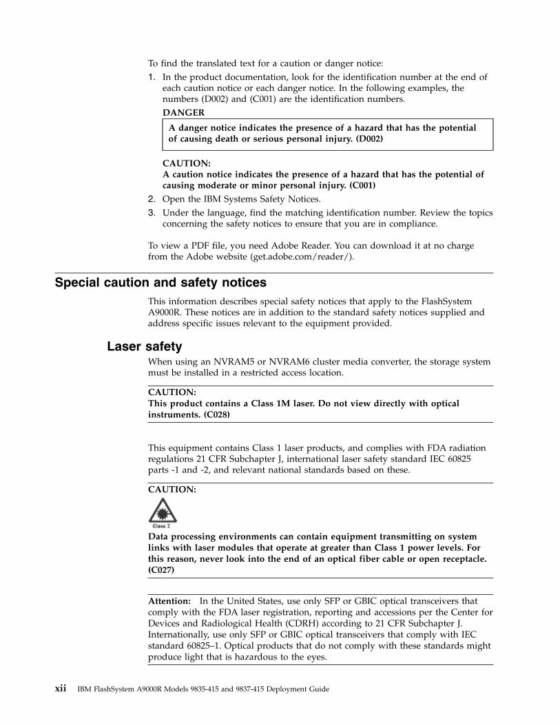
CAUTION:
Data processing environments can contain equipment transmitting on systemlinks with laser modules that operate at greater than Class 1 power levels. Forthis reason, never look into the end of an optical fiber cable or open receptacle.(C027)
Attention: In the United States, use only SFP or GBIC optical transceivers thatcomply with the FDA laser registration, reporting and accessions per the Center forDevices and Radiological Health (CDRH) according to 21 CFR Subchapter J.Internationally, use only SFP or GBIC optical transceivers that comply with IECstandard 60825–1. Optical products that do not comply with these standards mightproduce light that is hazardous to the eyes.
xii IBM FlashSystem A9000R Models 9835-415 and 9837-415 Deployment Guide
Usage restrictions: The optical ports of the modules must be terminated with anoptical connector or with a dust plug.
Ladder usageA step or platform ladder might be necessary to service higher modules.
Use an OSHA/CSA approved non-conductive step or platform ladder specified forat least a 136.4 kg (300 lb.) load capacity.
Fire suppression systemsA fire suppression system is the responsibility of the customer. The insuranceunderwriter, local fire marshal, or a local building inspector, or all three, must beconsulted in selecting a fire suppression system that provides the correct level ofcoverage and protection.
IBM® designs and manufactures equipment to internal and external standards thatrequire certain environments for reliable operation. Because IBM does not test anyequipment for compatibility with fire suppression systems, IBM does not makecompatibility claims of any kind nor does IBM provide recommendations on firesuppression systems.
Power cablesUse only IBM approved UL power cables.
For your safety, IBM provides a power cable with a grounded attachment plug touse with this IBM product. To avoid electrical shock, always use the power cableand plug with a correctly grounded outlet. IBM power cables used in the UnitedStates and Canada are listed by Underwriters Laboratories (UL) and certified bythe Canadian Standards Association (CSA). For units intended to be operated at115 volts: Use a UL-listed and CSA-certified cable set consisting of a minimum 18AWG, Type SVT or SJT, three-conductor cable, a maximum of 15 feet in length anda parallel blade, grounding-type attachment plug rated 15 amperes, 125 volts. Forunits intended to be operated at 230 volts (U.S. use), use a UL-listed andCSA-certified cable set consisting of a minimum 18 AWG, Type SVT or SJT,three-conductor cable, a maximum of 15 feet in length and a tandem blade,grounding-type attachment plug rated 15 amperes, 250 volts. For units intended tobe operated at 230 volts (outside the U.S.), use a cable set with a grounding typeattachment plug. The cable set must have the appropriate safety approvals for thecountry in which the equipment is to be installed. IBM power cables for a specificcountry or region are usually available only in that country or region.
Connect all power cables to a correctly wired and grounded electrical outlet.Ensure that the outlets supplies correct voltage and phase rotation according to thesystem rating plate. Ensure that all customer facility outlets are protected withcircuit breakers rated at maximum for 30 Amps. The power cable plugs operate asthe system main-disconnection method.
Note: For power cables outside of the U.S., IBM provides power cables with noconnector. It is the client's responsibility to install the correct power plug with theaide of a certified electrician. For power requirements, see “Power requirements”on page 26.
Safety and environmental notices xiii
Sound pressureHearing protection must be worn while you service the FlashSystem A9000Rsystem.
Attention: Depending upon local conditions, the sound pressure might exceed 85dB(A) during service operations. When working on the FlashSystem A9000Rsystem while either the front or rear door is in the open position, hearingprotection must be worn.
CAUTION:
Depending upon local conditions, the sound pressure might exceed 85dB(A) during service operations. Hearing protection must be worn when you arein a room that has an FlashSystem A9000R system while either the front or reardoor is open or when the front and rear doors are not installed.
Leakage currentThe FlashSystem A9000R system incorporates electromagnetic-interference filtercapacitors that are required to prevent electrical noise from penetrating the powergrid. A characteristic of filter capacitors, during normal operation, is a high amountof leakage current.
Depending on the storage configuration, this leakage current can reach 100 mA.
For the most reliable operation, do not use Ground Fault Circuit Interrupter(GFCI), Earth Leakage Circuit Breaker (ELCB), and Residual Current CircuitBreaker (RCCB) type circuit breakers with a FlashSystem A9000R system. TheFlashSystem A9000R system is certified for safe operation and is compliant withIEC, EN, UL, CSA 60950-1 standards. However, if leakage detection circuit breakersare required by local electrical practice, the breakers must be sized for aleakage-current rating of 300 mA or greater to reduce the risk of server outagecaused by erroneous and spurious tripping.
Site preparationThe IBM service representative can only minimally reposition the rack at theinstallation site, as needed to service the FlashSystem A9000R system. Thecustomer is responsible for using professional movers or riggers in the case ofequipment relocation or disposal.
xiv IBM FlashSystem A9000R Models 9835-415 and 9837-415 Deployment Guide
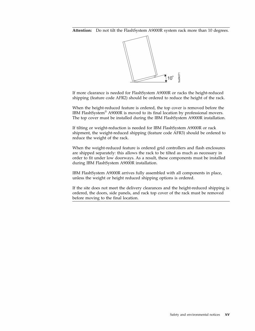
Attention: Do not tilt the FlashSystem A9000R system rack more than 10 degrees.
10
fsa9k071
If more clearance is needed for FlashSystem A9000R or racks the height-reducedshipping (feature code AFR2) should be ordered to reduce the height of the rack.
When the height-reduced feature is ordered, the top cover is removed before theIBM FlashSystem® A9000R is moved to its final location by professional movers.The top cover must be installed during the IBM FlashSystem A9000R installation.
If tilting or weight-reduction is needed for IBM FlashSystem A9000R or rackshipment, the weight-reduced shipping (feature code AFR3) should be ordered toreduce the weight of the rack.
When the weight-reduced feature is ordered grid controllers and flash enclosuresare shipped separately: this allows the rack to be tilted as much as necessary inorder to fit under low doorways. As a result, these components must be installedduring IBM FlashSystem A9000R installation.
IBM FlashSystem A9000R arrives fully assembled with all components in place,unless the weight or height reduced shipping options is ordered.
If the site does not meet the delivery clearances and the height-reduced shipping isordered, the doors, side panels, and rack top cover of the rack must be removedbefore moving to the final location.
Safety and environmental notices xv

DANGER
Heavy equipment - personal injury or equipment damage might result ifmishandled. Use only professional movers.
xiv
10
01
2
Environmental noticesThis publication contains all the required environmental notices for IBM Systemsproducts in 26 languages. The environmental notices that are included arelimitations, product recycling and disposal, product information, battery returnprogram, flat panel display, monitors and workstations, refrigeration, andwater-cooling system.
IBM Systems Environmental Notices and User Guide (ftp://public.dhe.ibm.com/systems/support/warranty/envnotices/environmental_notices_and_user_guide.pdf), Z125-5823
To view a PDF file, you need Adobe Reader. You can download it at no chargefrom the Adobe website (get.adobe.com/reader/).
xvi IBM FlashSystem A9000R Models 9835-415 and 9837-415 Deployment Guide
About this guide
This manual defines information regarding the deployment, configuration,preinstallation requirements for IBM FlashSystem A9000R models 9835-415 and9837-415. It is important to ensure that you meet all requirements to ensure a fastand reliable deployment and installation.
If you cannot meet the deployment and installation requirements explained in thisdocument, notify your IBM representative to devise an alternative solution.
Who should use this guideThis publication is for personnel that are involved in planning. Such personnelinclude IT facilities managers, individuals responsible for power, cooling, wiring,network, and general site environmental planning and setup.
Roles and responsibilitiesBoth IBM and the customer have roles and responsibilities that they must adhereto, in order to ensure proper workflow, timely successful installation, properlyconfigured Call Home and remote support, leading to a superior client experience.
Roles and responsibilities of the customerv Review the product Deployment Guidev Enable and work with the Remote Support Center (RSC) remote support in
performing remote data collection and supportv Work with the IBM Planning Representative (IPR), Service Representative (SSR),
Quality Practitioner (QPer), or other IBM personnel to fill out the Technical andDelivery Assessment (TDA) for accurate and quicker initial installation
v Provide and prepare a rack, adhering to the rack requirements, as specified inthis guide.
v Provide adequate staffing/resources to support this solution.v Provide sufficient bandwidth and host attachments to support this solution.v Provide necessary Ethernet cablingv Provide all initial host Fibre Channel (FC) and iSCSI cablingv Provide proper power receptacles to match the requirements for the IBM
FlashSystem A9000R orderedv Provide proper thermal dissipation, airflow and cooling, and environmental
requirementsv Provide proper floor space and clearancev Provide access for the IBM service representative (SSR), including laptop or
computer accessv Provide access for movers and vehiclesv Allow firewall access to Call Home serversv Setup IP host networkv Setup SAN host networkingv Download and install appropriate Host Attachment Kit (HAK)
© Copyright IBM Corp. 2016, 2017 xvii
v Install the Management Server from Fix Central for IBM Hyper-Scale ManagerUI use
v Perform logical configurationv Complete the host attachment planv Prepare Fibre Channel (FC) connectionsv Prepare raised floor, if required
Roles and responsibilities of IBM Service SupportRepresentatives (SSRs)v Complete Distant Learning (DL) education and hands-on education coursev Enroll in a hearing conservation programv Perform product installationv Configure Call Home and remote supportv Installation of software upgradesv Installation of hardware Engineering Change Notices (ECA) also known as Field
Bill of Materials (FBM)v Conduct product relocation, at customer requestv Perform break/fix repairsv Return of failed parts that are under warranty or have a Certified Spare Parts
Valuev Keep customers informed of service activitiesv Arrange time with customer/TA to facilitate upgradesv Assist with break/fix support as requested by Remote Support Center, Top Gun,
or PFE team memberv Complete accurate Quality Service Activity Reporting (QSAR) reporting
Note: Additional information can be found in your the customer Enterprise ClassSupport for Storage document, provided by the IBM Planning Representative (IPR).
Conventions used in this guideThese notices are used to highlight key information.
Tip: These notices provide important tips.
Note: These notices provide important guidance, or advice.
Important: These notices provide information or advice that might help you avoidinconvenient or difficult situations.
Attention: These notices indicate possible damage to programs, devices, or data.An attention notice is placed before the instruction or situation in which damagecan occur.
xviii IBM FlashSystem A9000R Models 9835-415 and 9837-415 Deployment Guide
CAUTION:
These notices indicate a situation that is potentially hazardous to peoplebecause of some existing condition or where a potentially dangerous situationmight develop because of some unsafe practice.
DANGER
These notices indicate a situation that is potentially lethal or hazardous topeople. For example, after a computer side panel is removed, exposedhigh-voltage wires might be lethal.
Related information and publicationsYou can find additional information and publications related to IBM FlashSystemA9000R on the following information sources.v IBM FlashSystem A9000R on IBM Knowledge Center (ibm.com/support/
knowledgecenter/STJKN5) – on which you can find the following relatedpublications:– IBM FlashSystem A9000R – Release Notes– IBM FlashSystem A9000R – Product Overview– IBM FlashSystem A9000R – Command-Line Interface (CLI) Reference Guide– IBM FlashSystem A9000 and IBM FlashSystem A9000R – Application
Programming Interface (API) Reference Guide– IBM Hyper-Scale Manager – Release Notes– IBM Hyper-Scale Manager – User Guide– IBM Hyper-Scale Manager – Representational State Transfer (REST) API
Specifications– IBM XIV Remote Support Proxy – Release Notes– IBM XIV Remote Support Proxy – Installation and User Guide
v IBM FlashSystem A9000 on IBM Knowledge Center (ibm.com/support/knowledgecenter/STJKMM) – on which you can find the following relatedpublications:– IBM FlashSystem A9000 – Release Notes– IBM FlashSystem A9000 – Product Overview– IBM FlashSystem A9000 – Deployment Guide– IBM FlashSystem A9000 – Command-Line Interface (CLI) Reference Guide– IBM FlashSystem A9000 and IBM FlashSystem A9000R – Application
Programming Interface (API) Reference Guide– IBM XIV Remote Support Proxy – Release Notes– IBM XIV Remote Support Proxy – Installation and User Guide
v IBM Flash Storage and Solutions marketing website (ibm.com/systems/storage/flash)
v IBM Storage Redbooks® website (redbooks.ibm.com/portals/storage)
About this guide xix

Getting information, help, and serviceIf you need help, service, technical assistance, or want more information about IBMproducts, you can find various sources to assist you. You can view the followingwebsites to get information about IBM products and services and to find the latesttechnical information and support.v IBM website (ibm.com®)v IBM Support Portal website (www.ibm.com/storage/support)v IBM Directory of Worldwide Contacts website (www.ibm.com/planetwide)
IBM Publications CenterThe IBM Publications Center is a worldwide central repository for IBM productpublications and marketing material.
The IBM Publications Center website (www.ibm.com/shop/publications/order/)offers customized search functions to help you find the publications that you need.You can view or download publications at no charge.
Sending or posting your commentsYour feedback is important in helping to provide the most accurate and highestquality information.
Procedure
To submit any comments about this guide:v Go to IBM FlashSystem A9000R on IBM Knowledge Center
(ibm.com/support/knowledgecenter/STJKN5), drill down to the relevant page,and then click the Feedback link that is located at the bottom of the page.
The feedback form is displayed and you can use it to enter and submit yourcomments privately.
v You can post a public comment on the Knowledge Center page that you areviewing, by clicking Add Comment. For this option, you must first log in toIBM Knowledge Center with your IBM ID.
v You can send your comments by email to [email protected]. Be sure toinclude the following information:– Exact publication title and product version– Publication form number (for example: GC01-0001-01)– Page, table, or illustration numbers that you are commenting on– A detailed description of any information that should be changed
xx IBM FlashSystem A9000R Models 9835-415 and 9837-415 Deployment Guide

Note: When you send information to IBM, you grant IBM a nonexclusive right touse or distribute the information in any way it believes appropriate withoutincurring any obligation to you.
About this guide xxi

xxii IBM FlashSystem A9000R Models 9835-415 and 9837-415 Deployment Guide
Chapter 1. Overview
IBM FlashSystem A9000R is a grid-scale, all-flash storage platform designed todrive your business into the cognitive era.
This guide defines deployment, planning, and preinstallation requirements for IBMFlashSystem A9000R storage systems. It is important to ensure that you meet allrequirements to help achieve a fast and reliable installation.
FlashSystem A9000R provides consistent, extreme performance for dynamic data atscale. The FlashSystem A9000R storage system integrates the microsecond latencyand high availability of IBM FlashCore® technology with grid architecture,comprehensive data reduction, and industry leading IBM software.
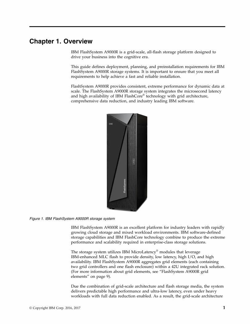
IBM FlashSystem A9000R is an excellent platform for industry leaders with rapidlygrowing cloud storage and mixed workload environments. IBM software-definedstorage capabilities and IBM FlashCore technology combine to produce the extremeperformance and scalability required in enterprise-class storage solutions.
The storage system utilizes IBM MicroLatency® modules that leverageIBM-enhanced MLC flash to provide density, low latency, high I/O, and highavailability. IBM FlashSystem A9000R aggregates grid elements (each containingtwo grid controllers and one flash enclosure) within a 42U integrated rack solution.(For more information about grid elements, see “FlashSystem A9000R gridelements” on page 9).
Due the combination of grid-scale architecture and flash storage media, the systemdelivers predictable high performance and ultra-low latency, even under heavyworkloads with full data reduction enabled. As a result, the grid-scale architecture
Figure 1. IBM FlashSystem A9000R storage system
© Copyright IBM Corp. 2016, 2017 1
maintains this performance by automatically self-optimizing workloads across allstorage resources without manual intervention. Secure multi-tenancy and quality ofservice (QoS) features help ensure that tenant service levels are not compromisedwithin your complex environment.
Advanced management capabilities allow it to integrate easily into your existingdata center infrastructure and with a wide variety of hypervisor and virtualizationsoftware, including VMware, OpenStack, and Microsoft.
For more information regarding the IBM FlashSystem A9000R grid scalearchitecture, see Introduction > Architecture in the IBM FlashSystem A9000R ProductOverview (SC27-8559).
Planning best practices and requirements
Good planning is essential for the successful setup and use of your FlashSystemA9000R. It ensures that you have everything you need and that you meet all theprerequisites for the storage system. It minimizes errors and helps for a fasterinstallation process.
Use this planning information to place the FlashSystem A9000R system, planpower and environmental needs, plan for software and storage needs, and preparefor unique configurations that are based on how you plan to use the storagesystem.
It is imperative that you work with the sales team, IBM Installation PlanningRepresentative (IPR), and IBM Service Representative (SSR) to capture informationneeded to install and configure the storage system. This information is collectedduring a Technical and Delivery Assessment (TDA) or Installation planningmeeting. This information must be collected prior to the commencement of theinstallation, or delays may occur.
CAUTION:
You must prepare your environment to handle the FlashSystem A9000Rsystem based on this planning information with assistance from an IBMinstallation planning representative (IPR) or an IBM service representative. Thefinal installation site within the computer room must be prepared before theequipment is delivered. If the site cannot be prepared before the delivery time,you must make arrangements to have the professional movers return to finishthe transportation later. Only professional movers can transport the equipment.The IBM service representative can minimally reposition the rack at theinstallation site, as needed to complete required service actions. You are alsoresponsible for using professional movers in the case of equipment relocation ordisposal.
If you cannot meet any of the installation requirements, notify your IBM servicerepresentative to devise alternative solutions.
2 IBM FlashSystem A9000R Models 9835-415 and 9837-415 Deployment Guide

Notes:
v This guide covers planning information for the IBM FlashSystem A9000Rintegrated rack storage system.For planning information for the IBM FlashSystem A9000 pod system, see IBMFlashSystem A9000 Deployment Guide, GC27-8564 on the IBM FlashSystem A9000Knowledge Center website (ibm.com/support/knowledgecenter/STJKMM).
v For information regarding management, automation, and access security, see thefollowing documentation, which can be found on the IBM FlashSystem A9000RKnowledge Center website (ibm.com/support/knowledgecenter/STJKN5):– IBM Hyper-Scale Manager User Guide, SC27-8560– IBM Hyper-Scale Manager Release Notes
– IBM FlashSystem A9000R Command-Line Interface (CLI) Reference Guide,SC27-8711
– IBM Hyper-Scale Manager REST API Specifications, SC27-6440
Chapter 1. Overview 3

4 IBM FlashSystem A9000R Models 9835-415 and 9837-415 Deployment Guide
Chapter 2. System specifications
This information compares general properties, performance, physical features, andhost connectivity for the IBM® FlashSystem™ A9000R storage system.
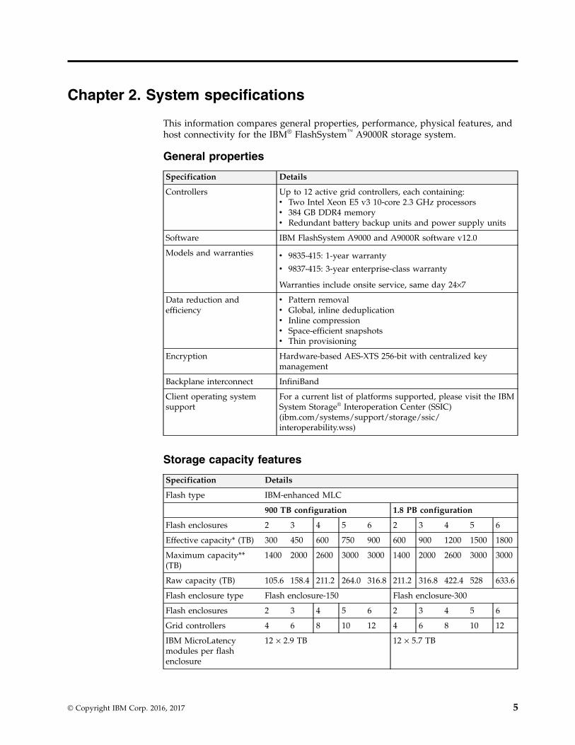
General properties
Specification Details
Controllers Up to 12 active grid controllers, each containing:v Two Intel Xeon E5 v3 10-core 2.3 GHz processorsv 384 GB DDR4 memoryv Redundant battery backup units and power supply units
Software IBM FlashSystem A9000 and A9000R software v12.0
Models and warranties v 9835-415: 1-year warranty
v 9837-415: 3-year enterprise-class warranty
Warranties include onsite service, same day 24×7
Data reduction andefficiency
v Pattern removalv Global, inline deduplicationv Inline compressionv Space-efficient snapshotsv Thin provisioning
Encryption Hardware-based AES-XTS 256-bit with centralized keymanagement
Backplane interconnect InfiniBand
Client operating systemsupport
For a current list of platforms supported, please visit the IBMSystem Storage® Interoperation Center (SSIC)(ibm.com/systems/support/storage/ssic/interoperability.wss)
Storage capacity features
Specification Details
Flash type IBM-enhanced MLC
900 TB configuration 1.8 PB configuration
Flash enclosures 2 3 4 5 6 2 3 4 5 6
Effective capacity* (TB) 300 450 600 750 900 600 900 1200 1500 1800
Maximum capacity**(TB)
1400 2000 2600 3000 3000 1400 2000 2600 3000 3000
Raw capacity (TB) 105.6 158.4 211.2 264.0 316.8 211.2 316.8 422.4 528 633.6
Flash enclosure type Flash enclosure-150 Flash enclosure-300
Flash enclosures 2 3 4 5 6 2 3 4 5 6
Grid controllers 4 6 8 10 12 4 6 8 10 12
IBM MicroLatencymodules per flashenclosure
12 × 2.9 TB 12 × 5.7 TB
© Copyright IBM Corp. 2016, 2017 5
Specification Details
*Typical effective capacity is the available capacity after system overhead (includingover-provisioning and RAID protection) and after the data reduction benefits of patternremoval, deduplication and compression. this assumes data reduction of up to a multipleof 5.26 to 1.
**Maximum capacity refers to the effective capacity provisioning limit.
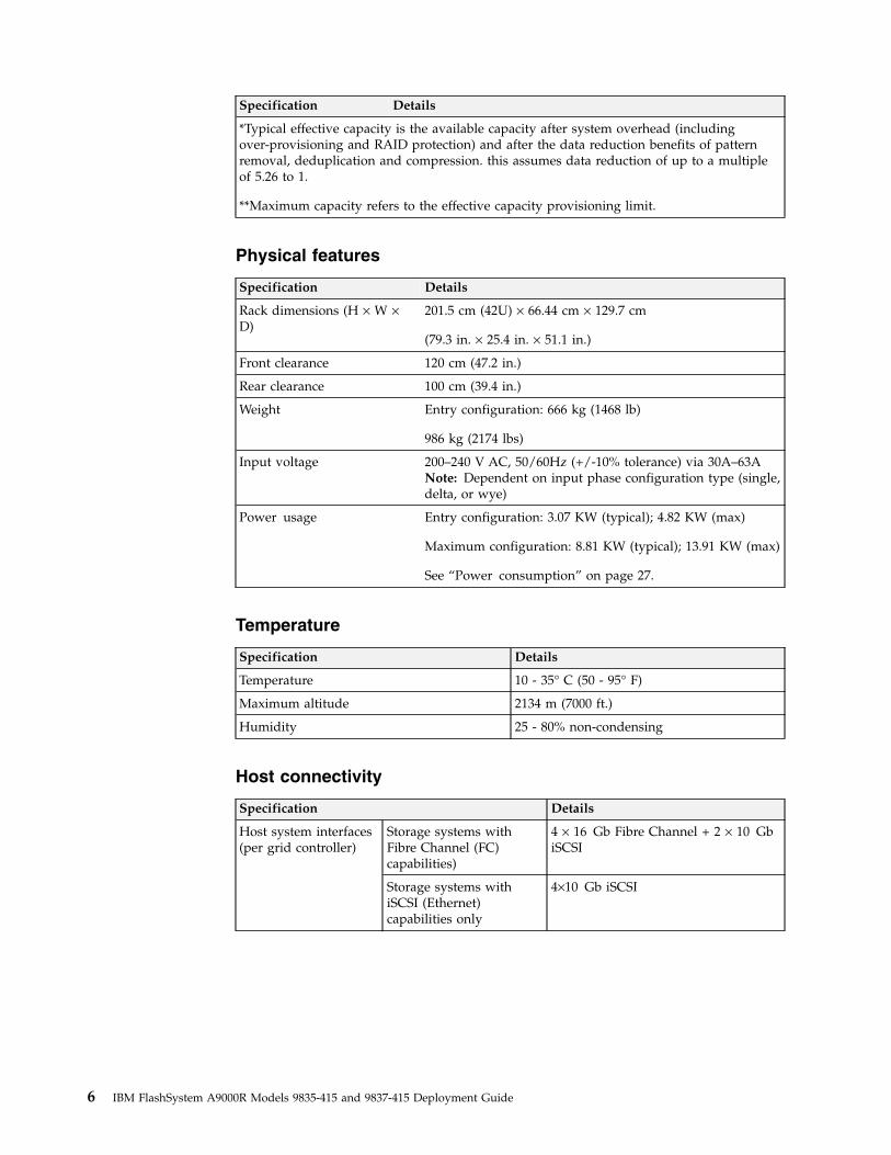
Physical features
Specification Details
Rack dimensions (H × W ×D)
201.5 cm (42U) × 66.44 cm × 129.7 cm
(79.3 in. × 25.4 in. × 51.1 in.)
Front clearance 120 cm (47.2 in.)
Rear clearance 100 cm (39.4 in.)
Weight Entry configuration: 666 kg (1468 lb)
986 kg (2174 lbs)
Input voltage 200–240 V AC, 50/60Hz (+/-10% tolerance) via 30A–63ANote: Dependent on input phase configuration type (single,delta, or wye)
Power usage Entry configuration: 3.07 KW (typical); 4.82 KW (max)
Maximum configuration: 8.81 KW (typical); 13.91 KW (max)
See “Power consumption” on page 27.
Temperature
Specification Details
Temperature 10 - 35° C (50 - 95° F)
Maximum altitude 2134 m (7000 ft.)
Humidity 25 - 80% non-condensing
Host connectivity
Specification Details
Host system interfaces(per grid controller)
Storage systems withFibre Channel (FC)capabilities)
4 × 16 Gb Fibre Channel + 2 × 10 GbiSCSI
Storage systems withiSCSI (Ethernet)capabilities only
4×10 Gb iSCSI
6 IBM FlashSystem A9000R Models 9835-415 and 9837-415 Deployment Guide
Specification Details
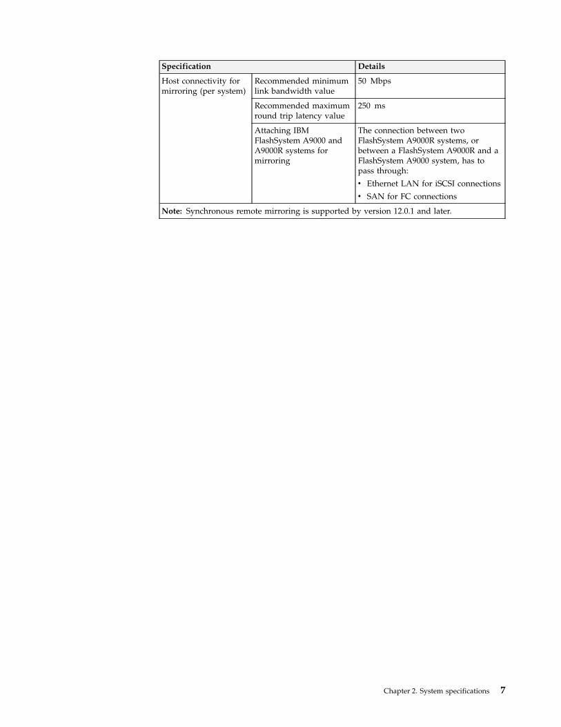
Host connectivity formirroring (per system)
Recommended minimumlink bandwidth value
50 Mbps
Recommended maximumround trip latency value
250 ms
Attaching IBMFlashSystem A9000 andA9000R systems formirroring
The connection between twoFlashSystem A9000R systems, orbetween a FlashSystem A9000R and aFlashSystem A9000 system, has topass through:
v Ethernet LAN for iSCSI connections
v SAN for FC connections
Note: Synchronous remote mirroring is supported by version 12.0.1 and later.
Chapter 2. System specifications 7

8 IBM FlashSystem A9000R Models 9835-415 and 9837-415 Deployment Guide
Chapter 3. Physical configuration options
Use these general guideline for determining and ordering the feature codes thatyou need to customize your IBM FlashSystem A9000R system.
Procedure
Note: Talk to your IBM planning representative (IPR) to help determine whichoptions are best for your needs.
To determine the required ordering information, answer the following questions:1. Which model best fits your warranty requirements?2. What are your capacity needs?3. What are your performance requirements?4. What type of host connectivity do you need?5. What type of power input do you have?6. Does the installation site meet the physical site requirements for the
FlashSystem A9000R and features that you plan to order? For example:v Can you space the racks to allow for sufficient floor strength?v Is there adequate cooling capacity to handle the new equipment?v Is sufficient power available?v Do you need 30A or 60A power cables?v Is water cooling required?
7. Do you require any of the following:v Any weight or height reduced shipping?v A radio frequency identification device (RFID) tag?
What to do next
See the following information on the various physical configuration options foryour IBM FlashSystem A9000R storage system.v “FlashSystem A9000R grid elements”v “Components and interconnect” on page 10v “Rack configurations” on page 11v “Flash enclosure components and feature codes” on page 13v “Grid controller components and feature codes” on page 14v “Rear-door heat exchanger” on page 15v “Weight-reduced shipping option” on page 17v “Height reduced shipping option” on page 17v “Radio frequency identification device option” on page 18
FlashSystem A9000R grid elementsA grid element is an orderable bundle that ensures only valid FlashSystem A9000Rrack configurations.
Each grid element contains two grid controllers and one flash enclosure, as shownin Figure 2 on page 10.
© Copyright IBM Corp. 2016, 2017 9
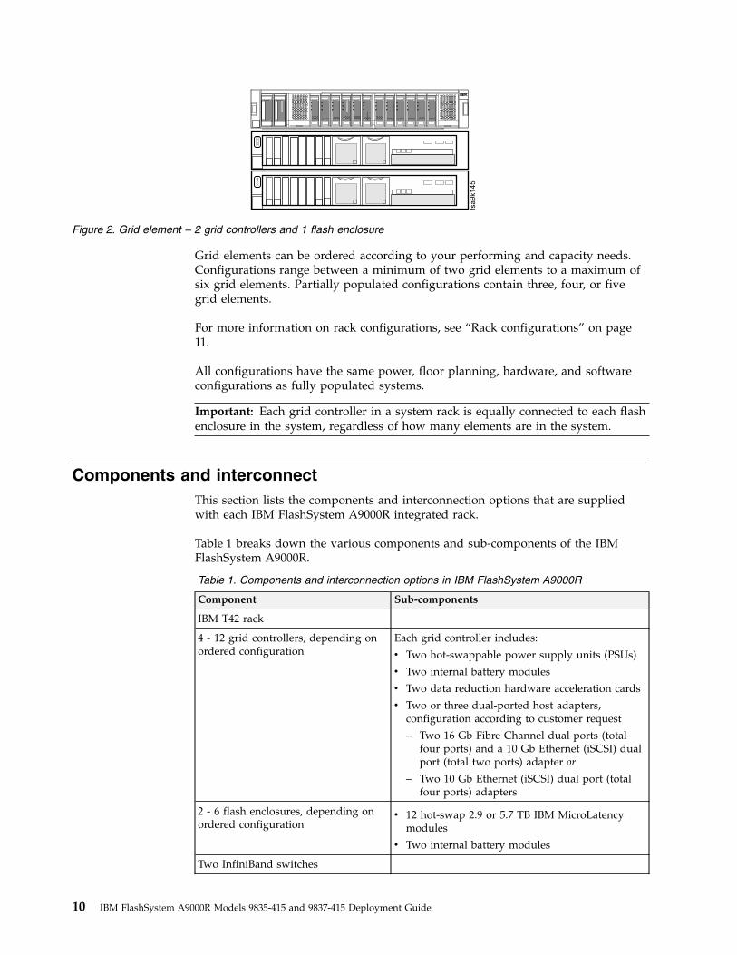
Grid elements can be ordered according to your performing and capacity needs.Configurations range between a minimum of two grid elements to a maximum ofsix grid elements. Partially populated configurations contain three, four, or fivegrid elements.
For more information on rack configurations, see “Rack configurations” on page11.
All configurations have the same power, floor planning, hardware, and softwareconfigurations as fully populated systems.
Important: Each grid controller in a system rack is equally connected to each flashenclosure in the system, regardless of how many elements are in the system.
Components and interconnectThis section lists the components and interconnection options that are suppliedwith each IBM FlashSystem A9000R integrated rack.
Table 1 breaks down the various components and sub-components of the IBMFlashSystem A9000R.
Table 1. Components and interconnection options in IBM FlashSystem A9000R
Component Sub-components
IBM T42 rack
4 - 12 grid controllers, depending onordered configuration
Each grid controller includes:
v Two hot-swappable power supply units (PSUs)
v Two internal battery modules
v Two data reduction hardware acceleration cards
v Two or three dual-ported host adapters,configuration according to customer request
– Two 16 Gb Fibre Channel dual ports (totalfour ports) and a 10 Gb Ethernet (iSCSI) dualport (total two ports) adapter or
– Two 10 Gb Ethernet (iSCSI) dual port (totalfour ports) adapters
2 - 6 flash enclosures, depending onordered configuration
v 12 hot-swap 2.9 or 5.7 TB IBM MicroLatencymodules
v Two internal battery modules
Two InfiniBand switches
fsa9k145
Figure 2. Grid element – 2 grid controllers and 1 flash enclosure
10 IBM FlashSystem A9000R Models 9835-415 and 9837-415 Deployment Guide
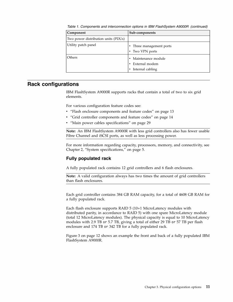
Table 1. Components and interconnection options in IBM FlashSystem A9000R (continued)
Component Sub-components
Two power distribution units (PDUs)
Utility patch panel v Three management ports
v Two VPN ports
Others v Maintenance module
v External modem
v Internal cabling
Rack configurationsIBM FlashSystem A9000R supports racks that contain a total of two to six gridelements.
For various configuration feature codes see:v “Flash enclosure components and feature codes” on page 13v “Grid controller components and feature codes” on page 14v “Main power cables specifications” on page 29
Note: An IBM FlashSystem A9000R with less grid controllers also has fewer usableFibre Channel and iSCSI ports, as well as less processing power.
For more information regarding capacity, processors, memory, and connectivity, seeChapter 2, “System specifications,” on page 5.
Fully populated rack
A fully populated rack contains 12 grid controllers and 6 flash enclosures.
Note: A valid configuration always has two times the amount of grid controllersthan flash enclosures.
Each grid controller contains 384 GB RAM capacity, for a total of 4608 GB RAM fora fully populated rack.
Each flash enclosure supports RAID 5 (10+1 MicroLatency modules withdistributed parity, in accordance to RAID 5) with one spare MicroLatency module(total 12 MicroLatency modules). The physical capacity is equal to 10 MicroLatencymodules with 2.9 TB or 5.7 TB, giving a total of either 29 TB or 57 TB per flashenclosure and 174 TB or 342 TB for a fully populated rack.
Figure 3 on page 12 shows an example the front and back of a fully populated IBMFlashSystem A9000R.
Chapter 3. Physical configuration options 11

Minimally populated rack
A minimally populated rack contains four grid controllers and two flashenclosures.
Each grid controller contains 384 GB RAM, for a total of 1536 GB RAM for aminimally populated rack.
Each flash enclosure supports RAID 5 (10+1 MicroLatency modules withdistributed parity, in accordance to RAID 5) with one spare MicroLatency module(total 12 MicroLatency modules). The physical capacity is equal to 10 MicroLatency
Figure 3. Fully-populated IBM FlashSystem A9000R
12 IBM FlashSystem A9000R Models 9835-415 and 9837-415 Deployment Guide
modules with 2.9 TB or 5.7 TB, giving a total of either 29 TB or 57 TB per flashenclosure and 58 TB or 114 TB for a minimally populated rack.
Figure 4 shows an example of the front and back of a minimally populated IBMFlashSystem A9000R.
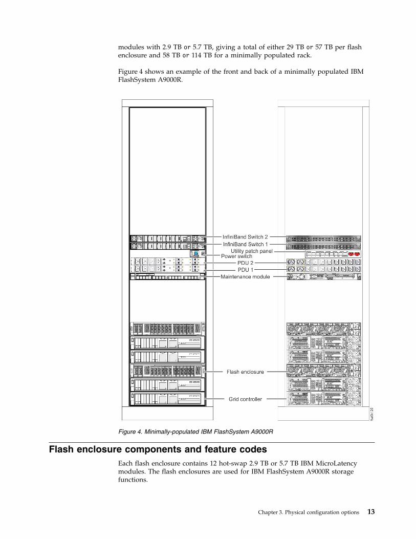
Flash enclosure components and feature codesEach flash enclosure contains 12 hot-swap 2.9 TB or 5.7 TB IBM MicroLatencymodules. The flash enclosures are used for IBM FlashSystem A9000R storagefunctions.
Figure 4. Minimally-populated IBM FlashSystem A9000R
Chapter 3. Physical configuration options 13
Each rack unit contains 2 - 6 flash enclosures, according to customer specifications.Figure 5 and Figure 6 illustrate the front and rear of the flash enclosure.
Table 2. Feature codes for flash enclosures
Description Feature code
Flash enclosure with 12 x 2.9 TB IBM MicroLatency modules AFE2
Flash enclosure with 12 x 5.7 TB IBM MicroLatency modules AFE3
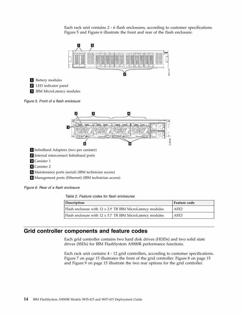
Grid controller components and feature codesEach grid controller contains two hard disk drives (HDDs) and two solid statedrives (SSDs) for IBM FlashSystem A9000R performance functions.
Each rack unit contains 4 - 12 grid controllers, according to customer specifications.Figure 7 on page 15 illustrates the front of the grid controller. Figure 8 on page 15and Figure 9 on page 15 illustrate the two rear options for the grid controller.
▌1▐ Battery modules
▌2▐ LED indicator panel
▌3▐ IBM MicroLatency modules
Figure 5. Front of a flash enclosure
▌1▐InfiniBand Adapters (two per canister)
▌2▐Internal interconnect Infiniband ports
▌3▐Canister 1
▌4▐Canister 2
▌5▐Maintenance ports (serial) (IBM technician access)
▌6▐Management ports (Ethernet) (IBM technician access)
Figure 6. Rear of a flash enclosure
14 IBM FlashSystem A9000R Models 9835-415 and 9837-415 Deployment Guide
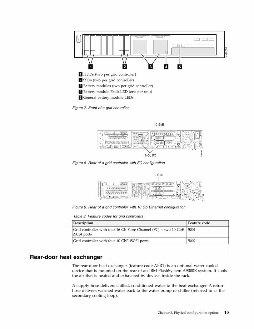
Table 3. Feature codes for grid controllers
Description Feature code
Grid controller with four 16 Gb Fibre Channel (FC) + two 10 GbEiSCSI ports
5001
Grid controller with four 10 GbE iSCSI ports 5002
Rear-door heat exchangerThe rear-door heat exchanger (feature code AFR1) is an optional water-cooleddevice that is mounted on the rear of an IBM FlashSystem A9000R system. It coolsthe air that is heated and exhausted by devices inside the rack.
A supply hose delivers chilled, conditioned water to the heat exchanger. A returnhose delivers warmed water back to the water pump or chiller (referred to as thesecondary cooling loop).
fsa
9k0
58
4 521 3
▌1▐HDDs (two per grid controller)
▌2▐SSDs (two per grid controller)
▌3▐Battery modules (two per grid controller)
▌4▐Battery module Fault LED (one per unit)
▌5▐General battery module LEDs
Figure 7. Front of a grid controller
Figure 8. Rear of a grid controller with FC configuration
Figure 9. Rear of a grid controller with 10 Gb Ethernet configuration
Chapter 3. Physical configuration options 15
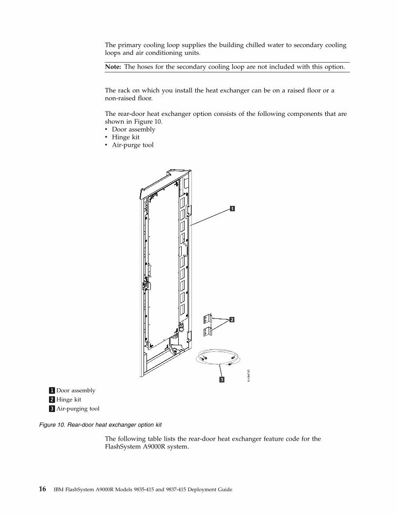
The primary cooling loop supplies the building chilled water to secondary coolingloops and air conditioning units.
Note: The hoses for the secondary cooling loop are not included with this option.
The rack on which you install the heat exchanger can be on a raised floor or anon-raised floor.
The rear-door heat exchanger option consists of the following components that areshown in Figure 10.v Door assemblyv Hinge kitv Air-purge tool
The following table lists the rear-door heat exchanger feature code for theFlashSystem A9000R system.
▌1▐Door assembly
▌2▐Hinge kit
▌3▐Air-purging tool
Figure 10. Rear-door heat exchanger option kit
16 IBM FlashSystem A9000R Models 9835-415 and 9837-415 Deployment Guide
Table 4. Rear-door heat exchanger features
Feature description Feature code
Rear-door heat exchanger AFR1
See “Preparing for the rear-door heat exchanger” on page 26 for information aboutthe requirements for preparing the installation site before the rear-door heatexchanger feature can be installed.
Weight-reduced shipping optionThis information describes the Weight Reduction shipping option for the storagesystem, feature code AFR3.
IBM offers weight reduced shipping for all IBM FlashSystem A9000R systemconfigurations. This optional feature provides that the weight of the rack is onlyapproximately 440 kg (970 lb) for traversal at the delivery site.
This option is ordered for installations where receiving an assembled storage unit,or ordering feature code AFR2 would be impractical, due to greater weightlimitations.
The unit is delivered fully tested but partially disassembled into several easilytransported subassemblies. This feature allows racks to be safely transported onlower weight capacity elevators.
At the installation site the system is unpacked by IBM technicians, and the frontdoor, rear door and side covers are temporarily removed so that the rack assemblycan then be carried up stairs, hoisted via crane through windows, tipped to fitthrough low doorways, and rolled through low doorways in the customer's facility.
At the final destination, all devices that were shipped separately can be installed.
A fully configured FlashSystem A9000R system, including packaging, weighsapproximately 986 kg (2174 lbs).
Attention: The storage system must not be tilted more than 10 degrees.
Note: This option greatly increases the system installation time. Onsitecoordination is needed for both the IBM service representative and the professionalmovers.
Height reduced shipping optionThis information describes the Height Reduction shipping option for IBMFlashSystem A9000R, feature code AFR2.
If your site does not meet the delivery clearances that are shown in “Rackdimensions and service clearance requirements” on page 22, the height reducedshipping option can be ordered to reduce the height of the rack by 30 cm (11.8 in.)
Chapter 3. Physical configuration options 17
After the rack is delivered, the IBM service representative removes the rack topcover so that the rack can be moved to the final location. Only professional moverscan transport the equipment.
After the rack is in its final location, the IBM service representative must return tocomplete the installation, including reinstalling the rack top cover.
A fully configured FlashSystem A9000R system, including packaging, weighsapproximately 986 kg (2174 lbs) with dimensions of 66 cm × 118 cm(26 in. × 46.5 in.).
Attention: The storage system must not be tilted more than 10 degrees.
Note: This option greatly increases the system installation time. Onsitecoordination is needed for both the IBM service representative and the professionalmovers.
Radio frequency identification device optionIBM offers an optional radio frequency identification device (RFID) for the storagesystem, feature code AFR5.
If you use frequency identification device (RFID) technology to track equipment inyour data centers, you can order the RFID option to attach an RFID tag to systemracks.
This RFID is designed to meet the performance and numbering specification asoutlined by the radio frequency identification specifications. For information aboutthe specification, see the Financial Services Technology Consortium website(www.bits.org/?id=29).
Important: This option is applicable only in environments that can use the correctRFID reading technology. Before you order this option, review the RFIDcapabilities with your IBM service representative.
When this option is ordered, IBM attaches one RFID tag per rack. Order one RFIDoption for each FlashSystem A9000R that you want to track. This option does nottag individual components.
This option can be ordered only when a new rack is ordered. The RFID optioncannot be ordered as a miscellaneous equipment specification (MES).
Important: If the tag must be replaced for an IBM FlashSystem A9000R system,ensure that you update the asset-management database with the new RFIDnumber for that FlashSystem A9000R.
18 IBM FlashSystem A9000R Models 9835-415 and 9837-415 Deployment Guide
Chapter 4. Physical installation site requirements
The location where you plan to install the storage system must meet allrequirements.
Plan your installation site with assistance from an IBM installation planningrepresentative (IPR) or an IBM service representative.
Prepare the site in advance so that professional movers or riggers can transport theequipment to the final site within the computer room. If the site cannot beprepared before the delivery time, you must make arrangements to have theprofessional movers return to finish the transportation later.
Attention: Only professional movers can transport the equipment.
An IBM service representative installs the storage system. The IBM servicerepresentative can only minimally reposition the rack within the room, as neededto complete required service actions.
Professional movers or riggers are required to transport the FlashSystem A9000Rrack as close to the installation site as possible because of its weight.
Note: Professional movers or riggers are also required to relocate or dispose of theFlashSystem A9000R system.
The physical installation site requirements are listed in the following sections:v “Floor and space requirements”v “Power requirements” on page 26v “Environmental requirements” on page 32v “Planning for the rear-door heat exchanger” on page 38v “Site security considerations” on page 60
Floor and space requirementsEnsure that the location of the FlashSystem A9000R system meets floor and spacerequirements.
Procedure
Complete the following steps to ensure that the planned installation location meetsspace and floor load requirements:1. Decide whether the FlashSystem A9000R system is to be installed on a raised
floor. See “Raised or non-raised floor considerations” on page 20.2. Determine whether the floor meets the floor-load requirements for the
FlashSystem A9000R system. See “Floor-load requirements” on page 21.3. Calculate the amount of space needed for the rack footprint and service
clearance requirements. See “Rack dimensions and service clearancerequirements” on page 22.
© Copyright IBM Corp. 2016, 2017 19
4. Determine where to place the rack in the installation site, based on thefloor-load and space requirements.
5. If the location has a raised floor, prepare the raised floor with cable cutouts andrequired ventilation. See “Preparing for raised-floor installation and cabling” onpage 24.
6. If the location is not a raised floor, resolve any safety concerns that are causedby the location of overhead-cable exits and cable routing. See “Preparing fornon-raised-floor installation and cabling” on page 25.
7. Provide your IBM service representative with the following information beforethe installation:a. Whether under-floor or over-head power-cabling scheme is to be used.b. The distance of the rack from the power receptacles.
8. If a rear-door heat exchanger is being ordered, be sure to follow instructions in“Preparing for the rear-door heat exchanger” on page 26.
9. If absorbent padding is used where the rack casters (wheels) are located, besure to follow instructions in “Bottom rack dimensions” on page 23.
Raised or non-raised floor considerationsThe IBM FlashSystem A9000R storage system can be installed on a raised or anon-raised floor.
Raised floor considerations
Installing the racks on a raised floor provides the following benefits:v Improves operational efficiency and provides greater flexibility in the
arrangement of equipment.v Increases air circulation for better cooling.v Protects the interconnecting cables and power receptacles.v Prevents tripping hazards because cables can be routed underneath the raised
floor.
When you install on a raised floor, consider the following factors:v The raised floor must be constructed of fire-resistant or noncombustible material.v Avoid the exposure of metal or highly conductive material at ground potential
to the walking surface when a metallic raised floor structure is used. Suchexposure is considered an electrical safety hazard.
v The raised floor height must be at least 30.5 cm (12 in.). Clearance must beadequate to accommodate interconnecting cables, Fibre Channel (FC) cableraceways, power distribution, and any piping that is present under the floor.Floors with greater raised floor heights allow for better equipment cooling.
v When a raised floor tile is cut for cable entry or air supply, an extra floor tilesupport (pedestal) might be required to restore the structural integrity of thepanel to the previous requirement.
v The use of a protective covering (such as plywood, tempered masonite, orplyron) is required to prevent damage to floor tiles, carpeting, and panels whileequipment is being moved into or is relocated within the installation site. Whenthe equipment is moved, the dynamic load on the casters is greater than whenthe equipment is stationary.
v Concrete subfloors require treatment to prevent the release of dust.
20 IBM FlashSystem A9000R Models 9835-415 and 9837-415 Deployment Guide
v Use noncombustible protective molding to eliminate sharp edges on all floorcutouts to prevent damage to cables and hoses, and to prevent casters fromrolling into the floor cutout.
v Seal raised-floor cable openings to prevent the escape of chilled air.v Pedestals must be firmly attached to the structural (concrete) floor by using an
adhesive.
For more information, see “Preparing for raised-floor installation and cabling” onpage 24.
Non-raised floor considerations
Raised floors are preferred because they provide better support for the cabling andto ensure efficient cooling for the FlashSystem A9000R system; however, overheadcabling at the rear of the rack is available when the FlashSystem A9000R system isinstalled on a non-raised floor.
Unlike raised-floor cabling, the installation planning, cable length, and the racklocation, in relation to the cable opening at the top of the rack, are critical to thesuccessful installation when using overhead cabling.
For more information, see “Preparing for non-raised-floor installation and cabling”on page 25.
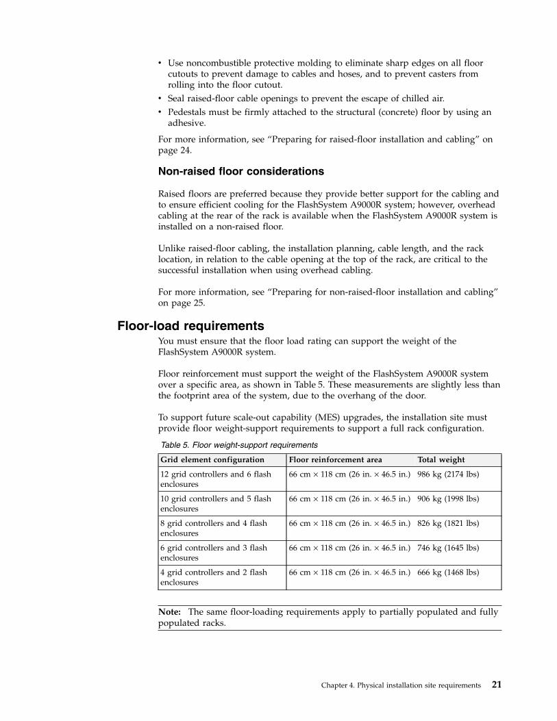
Floor-load requirementsYou must ensure that the floor load rating can support the weight of theFlashSystem A9000R system.
Floor reinforcement must support the weight of the FlashSystem A9000R systemover a specific area, as shown in Table 5. These measurements are slightly less thanthe footprint area of the system, due to the overhang of the door.
To support future scale-out capability (MES) upgrades, the installation site mustprovide floor weight-support requirements to support a full rack configuration.
Table 5. Floor weight-support requirements
Grid element configuration Floor reinforcement area Total weight
12 grid controllers and 6 flashenclosures
66 cm × 118 cm (26 in. × 46.5 in.) 986 kg (2174 lbs)
10 grid controllers and 5 flashenclosures
66 cm × 118 cm (26 in. × 46.5 in.) 906 kg (1998 lbs)
8 grid controllers and 4 flashenclosures
66 cm × 118 cm (26 in. × 46.5 in.) 826 kg (1821 lbs)
6 grid controllers and 3 flashenclosures
66 cm × 118 cm (26 in. × 46.5 in.) 746 kg (1645 lbs)
4 grid controllers and 2 flashenclosures
66 cm × 118 cm (26 in. × 46.5 in.) 666 kg (1468 lbs)
Note: The same floor-loading requirements apply to partially populated and fullypopulated racks.
Chapter 4. Physical installation site requirements 21
The rear-door heat exchanger adds more weight to the rack. For information aboutthe weight of an empty and filled door, see “Rear-door heat exchanger” on page15.
To ensure that all requirements are met, obtain the service of a qualified structuralengineer to prepare the floor.
Important: If you do not know or are not certain about the floor-load rating of theinstallation site, you must check with the building engineer or another appropriateperson.
Rack dimensions and service clearance requirementsThe installation site must accommodate the rack dimensions and minimum serviceclearance for the FlashSystem A9000R system.
The IBM service representative must have enough space to open the front and rearcovers to service the FlashSystem A9000R system, including removing componentsand other assemblies from the FlashSystem A9000R system.
Notes:
v You can position racks no closer than 45 cm (17.7 in.) to a wall.v You can position racks alongside (next to) other racks.v Because several rack designs are available from IBM and other vendors, space
between adjacent racks might be required to open the door for service. You mustdetermine the space requirement at the time of installation.
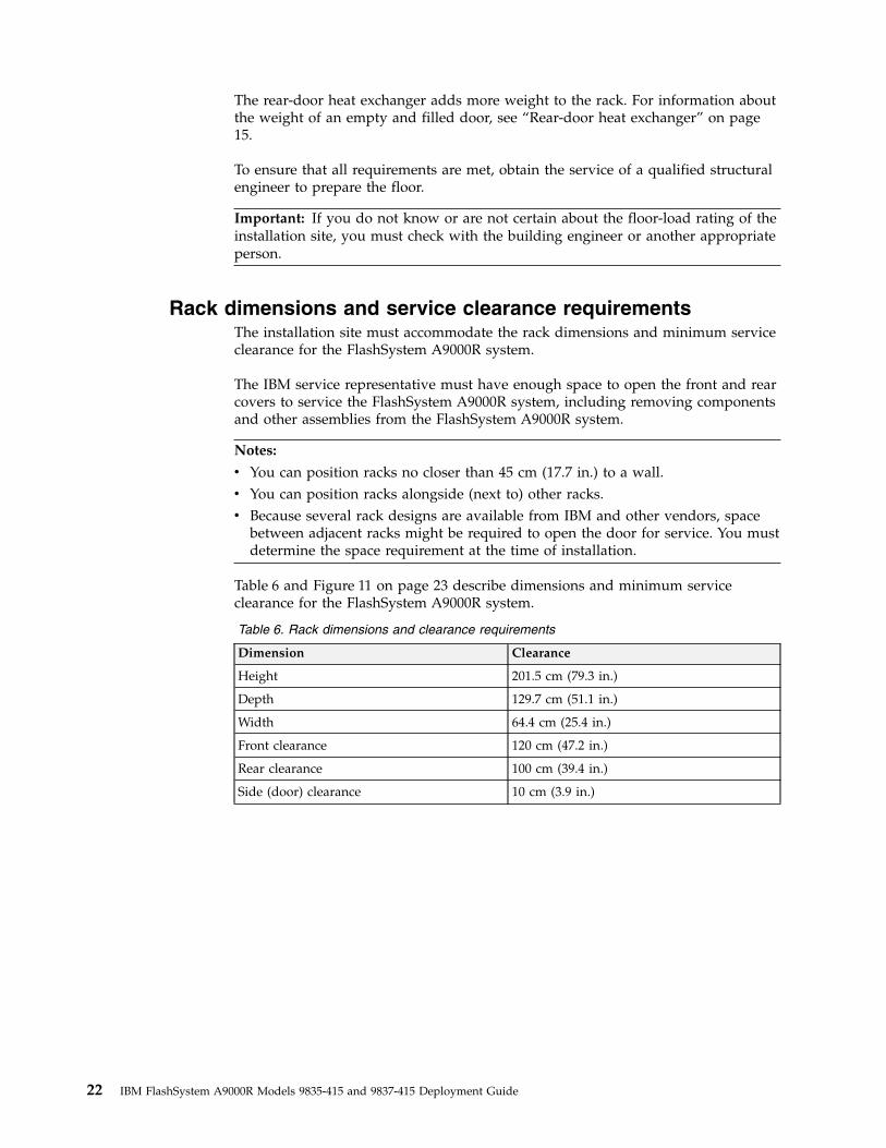
Table 6 and Figure 11 on page 23 describe dimensions and minimum serviceclearance for the FlashSystem A9000R system.
Table 6. Rack dimensions and clearance requirements
Dimension Clearance
Height 201.5 cm (79.3 in.)
Depth 129.7 cm (51.1 in.)
Width 64.4 cm (25.4 in.)
Front clearance 120 cm (47.2 in.)
Rear clearance 100 cm (39.4 in.)
Side (door) clearance 10 cm (3.9 in.)
22 IBM FlashSystem A9000R Models 9835-415 and 9837-415 Deployment Guide
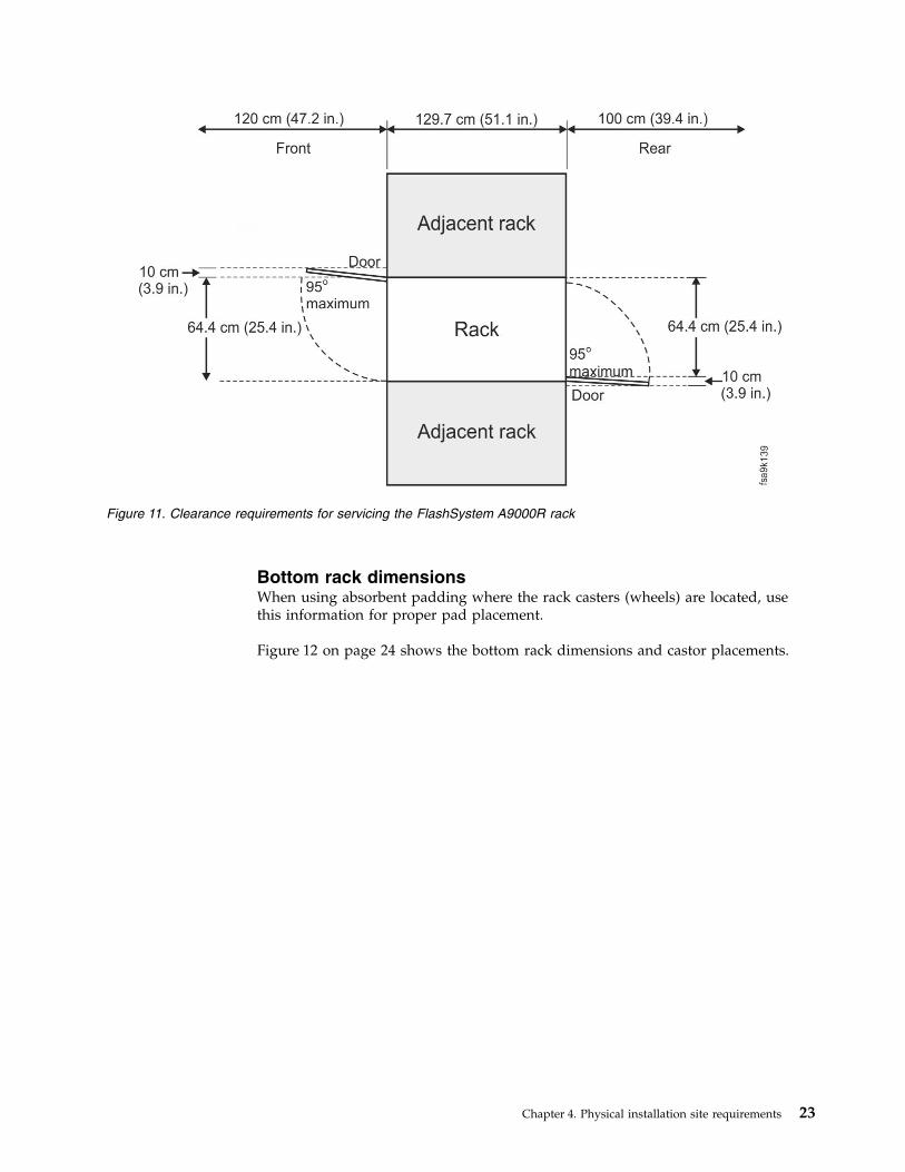
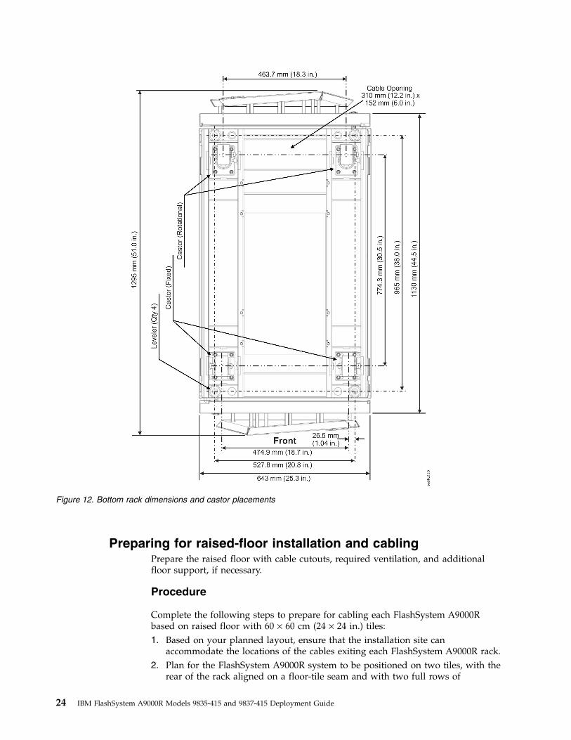
Bottom rack dimensionsWhen using absorbent padding where the rack casters (wheels) are located, usethis information for proper pad placement.
Figure 12 on page 24 shows the bottom rack dimensions and castor placements.
Figure 11. Clearance requirements for servicing the FlashSystem A9000R rack
Chapter 4. Physical installation site requirements 23
Preparing for raised-floor installation and cablingPrepare the raised floor with cable cutouts, required ventilation, and additionalfloor support, if necessary.
Procedure
Complete the following steps to prepare for cabling each FlashSystem A9000Rbased on raised floor with 60 × 60 cm (24 × 24 in.) tiles:1. Based on your planned layout, ensure that the installation site can
accommodate the locations of the cables exiting each FlashSystem A9000R rack.2. Plan for the FlashSystem A9000R system to be positioned on two tiles, with the
rear of the rack aligned on a floor-tile seam and with two full rows of
Figure 12. Bottom rack dimensions and castor placements
24 IBM FlashSystem A9000R Models 9835-415 and 9837-415 Deployment Guide
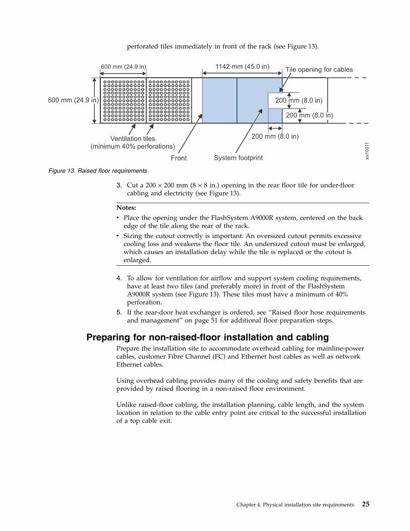
perforated tiles immediately in front of the rack (see Figure 13).
3. Cut a 200 × 200 mm (8 × 8 in.) opening in the rear floor tile for under-floorcabling and electricity (see Figure 13).
Notes:
v Place the opening under the FlashSystem A9000R system, centered on the backedge of the tile along the rear of the rack.
v Sizing the cutout correctly is important. An oversized cutout permits excessivecooling loss and weakens the floor tile. An undersized cutout must be enlarged,which causes an installation delay while the tile is replaced or the cutout isenlarged.
4. To allow for ventilation for airflow and support system cooling requirements,have at least two tiles (and preferably more) in front of the FlashSystemA9000R system (see Figure 13). These tiles must have a minimum of 40%perforation.
5. If the rear-door heat exchanger is ordered, see “Raised floor hose requirementsand management” on page 51 for additional floor preparation steps.
Preparing for non-raised-floor installation and cablingPrepare the installation site to accommodate overhead cabling for mainline-powercables, customer Fibre Channel (FC) and Ethernet host cables as well as networkEthernet cables.
Using overhead cabling provides many of the cooling and safety benefits that areprovided by raised flooring in a non-raised floor environment.
Unlike raised-floor cabling, the installation planning, cable length, and the systemlocation in relation to the cable entry point are critical to the successful installationof a top cable exit.
Figure 13. Raised floor requirements
Chapter 4. Physical installation site requirements 25
Notes:
v Main power cables are routed to the rack by the customer, and internally routedand connected by an IBM service representative.
v Host-attachment cables are internally routed and connected by either thecustomer or by an IBM service representative.
v All remaining cables are internally routed and connected by an IBM servicerepresentative.
If the rear-door heat exchanger is ordered, see “Non-raised floor hose requirementsand management” on page 55 for more floor preparation steps.
Installation and safety requirements
If the cables are too long, there might not be enough room inside of the rack tohandle the extra length and the extra cable might interfere with the servicing tasks,preventing concurrent repair.
IBM Corporate Safety restricts the servicing of your overhead equipment to amaximum of 10 feet from the floor. Therefore, your power source must not exceed10 feet from the floor and must be within 5 feet of the top of the rack.
Servicing any overhead equipment higher than 10 feet requires a special bidcontract. Contact your IBM Representative for more information about special bids.
Preparing for the rear-door heat exchangerAn optional rear-door heat exchanger (feature code AFR1) may be ordered to helpcool your system.
To complete the rear-door heat exchanger site preparation, follow the instructionsin “Planning for the rear-door heat exchanger” on page 38.
Power requirementsEnsure that your operating environment meets the AC-power and voltagerequirements.
The FlashSystem A9000R system is designed with backup battery modules in orderto maintain power to the storage system in the event of an AC-power loss.
The FlashSystem A9000R system has redundant main power cables. Fortwo-main-power-cable configuration, you must supply power from twoindependent sources of electricity.
Consult with an IBM service representative to discuss power source options for thefour-main-power-cable configuration.
Note: Removing all AC power from the FlashSystem A9000R system causes anemergency shutdown. All modified data is then saved to drives, and the systemturns off within 5 minutes.
26 IBM FlashSystem A9000R Models 9835-415 and 9837-415 Deployment Guide
Customer responsibilitiesv You must supply enough branch circuits to prevent overloading from the
equipment that you install.v You must ensure that each electrical outlet is correctly wired and grounded to
prevent an electrical shock.
IBM responsibilitiesv The IBM service representative completes several checks, including voltage and
grounding checks before the power to the FlashSystem A9000R system isconnected.
v The IBM service representative connects power to the racks and initially powerson the equipment.
Power outlet requirements
Ensure that the installation site has the required power outlets.
Two independent power outlets are required for the two main power cords thatare needed by each FlashSystem A9000R system.
Important: To eliminate a single point of failure, the outlets must be independent.This means that each outlet must use a separate power source and each powersource must have its own wall circuit breaker.
For the most reliable operation, do not use Ground Fault Circuit Interrupter(GFCI), Earth Leakage Circuit Breaker (ELCB), and Residual Current CircuitBreaker (RCCB) type circuit breakers with the FlashSystem A9000R system.
The FlashSystem A9000R system is certified for safe operation and is compliantwith IEC, EN, UL, CSA 60950-1 standards. However, if leakage detection circuitbreakers are required by local electrical practice, the breakers must be sized for aleakage-current rating of 100 mA or greater to reduce the risk of server outagecaused by erroneous and spurious tripping.
Power sourcesSeveral AC power source configurations are available.v Four 60/63 A, 200-240 V AC, North American, EMEA, and Japan single-phase
receptacles, each connected to a different power source.v Two 60 A, 200-240 V AC, US and Japan delta three-phase receptacles, each
connected to a different power source.v Two 30/32 A, 200-240 V AC (Line-to-Neutral [LN]), EMEA WYE three-phase
receptacles, each connected to a different power source
The storage system is protected from a power outage by internal backup batterymodules. However, you can reduce the risk of a power outage by connecting thesystem to an external uninterruptible power supply, a backup generator, or both.
Power consumptionThis information describes the power consumption for partial and full rackconfigurations.
Table 7 on page 28 lists the power consumption for each rack configuration.
Chapter 4. Physical installation site requirements 27
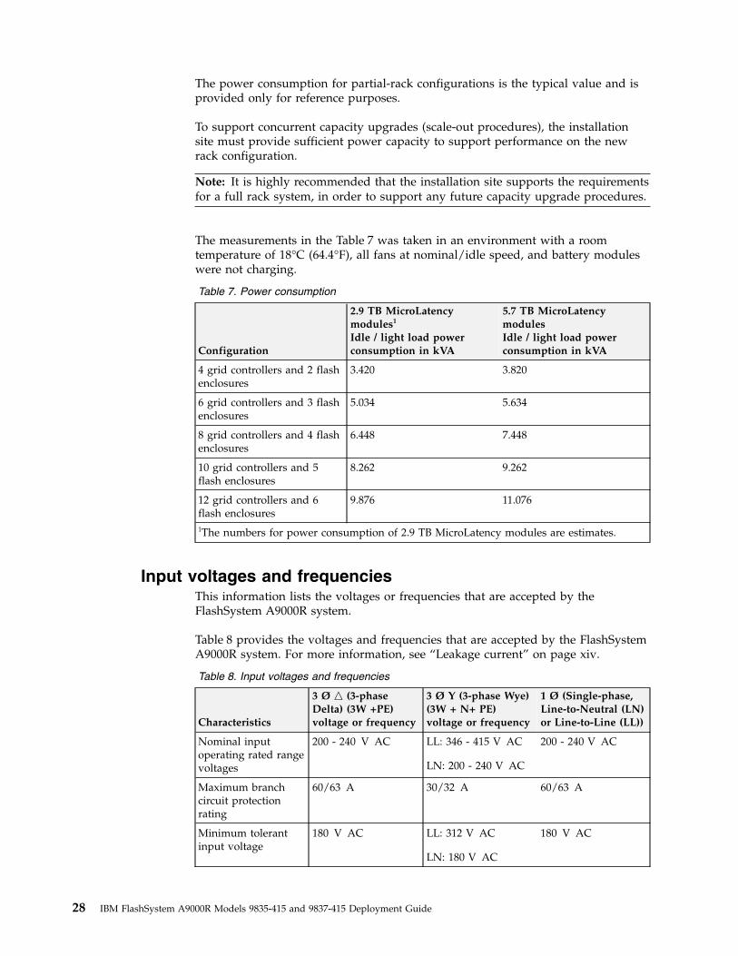
The power consumption for partial-rack configurations is the typical value and isprovided only for reference purposes.
To support concurrent capacity upgrades (scale-out procedures), the installationsite must provide sufficient power capacity to support performance on the newrack configuration.
Note: It is highly recommended that the installation site supports the requirementsfor a full rack system, in order to support any future capacity upgrade procedures.
The measurements in the Table 7 was taken in an environment with a roomtemperature of 18°C (64.4°F), all fans at nominal/idle speed, and battery moduleswere not charging.
Table 7. Power consumption
Configuration
2.9 TB MicroLatencymodules1
Idle / light load powerconsumption in kVA
5.7 TB MicroLatencymodulesIdle / light load powerconsumption in kVA
4 grid controllers and 2 flashenclosures
3.420 3.820
6 grid controllers and 3 flashenclosures
5.034 5.634
8 grid controllers and 4 flashenclosures
6.448 7.448
10 grid controllers and 5flash enclosures
8.262 9.262
12 grid controllers and 6flash enclosures
9.876 11.076
1The numbers for power consumption of 2.9 TB MicroLatency modules are estimates.
Input voltages and frequenciesThis information lists the voltages or frequencies that are accepted by theFlashSystem A9000R system.
Table 8 provides the voltages and frequencies that are accepted by the FlashSystemA9000R system. For more information, see “Leakage current” on page xiv.
Table 8. Input voltages and frequencies
Characteristics
3 Ø n (3-phaseDelta) (3W +PE)voltage or frequency
3 Ø Y (3-phase Wye)(3W + N+ PE)voltage or frequency
1 Ø (Single-phase,Line-to-Neutral (LN)or Line-to-Line (LL))
Nominal inputoperating rated rangevoltages
200 - 240 V AC LL: 346 - 415 V AC
LN: 200 - 240 V AC
200 - 240 V AC
Maximum branchcircuit protectionrating
60/63 A 30/32 A 60/63 A
Minimum tolerantinput voltage
180 V AC LL: 312 V AC
LN: 180 V AC
180 V AC
28 IBM FlashSystem A9000R Models 9835-415 and 9837-415 Deployment Guide
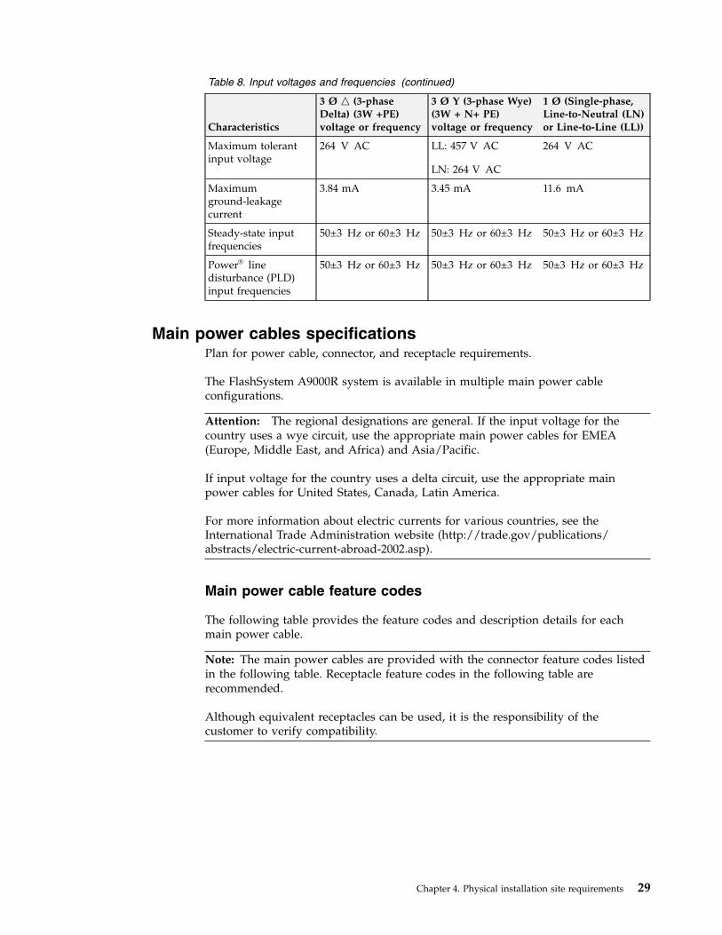
Table 8. Input voltages and frequencies (continued)
Characteristics
3 Ø n (3-phaseDelta) (3W +PE)voltage or frequency
3 Ø Y (3-phase Wye)(3W + N+ PE)voltage or frequency
1 Ø (Single-phase,Line-to-Neutral (LN)or Line-to-Line (LL))
Maximum tolerantinput voltage
264 V AC LL: 457 V AC
LN: 264 V AC
264 V AC
Maximumground-leakagecurrent
3.84 mA 3.45 mA 11.6 mA
Steady-state inputfrequencies
50±3 Hz or 60±3 Hz 50±3 Hz or 60±3 Hz 50±3 Hz or 60±3 Hz
Power® linedisturbance (PLD)input frequencies
50±3 Hz or 60±3 Hz 50±3 Hz or 60±3 Hz 50±3 Hz or 60±3 Hz
Main power cables specificationsPlan for power cable, connector, and receptacle requirements.
The FlashSystem A9000R system is available in multiple main power cableconfigurations.
Attention: The regional designations are general. If the input voltage for thecountry uses a wye circuit, use the appropriate main power cables for EMEA(Europe, Middle East, and Africa) and Asia/Pacific.
If input voltage for the country uses a delta circuit, use the appropriate mainpower cables for United States, Canada, Latin America.
For more information about electric currents for various countries, see theInternational Trade Administration website (http://trade.gov/publications/abstracts/electric-current-abroad-2002.asp).
Main power cable feature codes
The following table provides the feature codes and description details for eachmain power cable.
Note: The main power cables are provided with the connector feature codes listedin the following table. Receptacle feature codes in the following table arerecommended.
Although equivalent receptacles can be used, it is the responsibility of thecustomer to verify compatibility.
Chapter 4. Physical installation site requirements 29
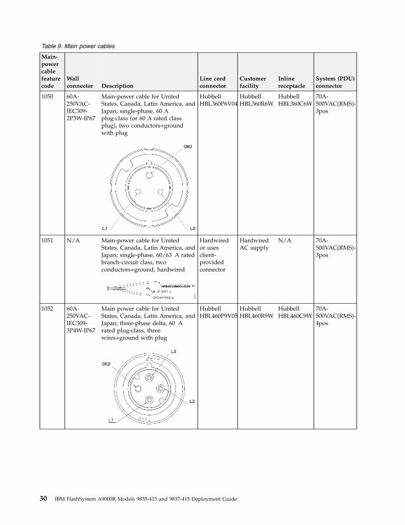
Table 9. Main power cables
Main-powercablefeaturecode
Wallconnector Description
Line cordconnector
Customerfacility
Inlinereceptacle
System (PDU)connector
1050 60A-250VAC-IEC309-2P3W-IP67
Main-power cable for UnitedStates, Canada, Latin America, andJapan; single-phase, 60 Aplug-class (or 60 A rated classplug), two conductors+groundwith plug
HubbellHBL360P6V04
HubbellHBL360R6W
HubbellHBL360C6W
70A-500VAC(RMS)-3pos
1051 N/A Main-power cable for UnitedStates, Canada, Latin America, andJapan; single-phase, 60/63 A ratedbranch-circuit class, twoconductors+ground, hardwired
Hardwiredor usesclient-providedconnector
HardwiredAC supply
N/A 70A-500VAC(RMS)-3pos
1052 60A-250VAC-IEC309-3P4W-IP67
Main power cable for UnitedStates, Canada, Latin America, andJapan; three-phase delta, 60 Arated plug-class, threewires+ground with plug
HubbellHBL460P9V05
HubbellHBL460R9W
HubbellHBL460C9W
70A-500VAC(RMS)-4pos
30 IBM FlashSystem A9000R Models 9835-415 and 9837-415 Deployment Guide
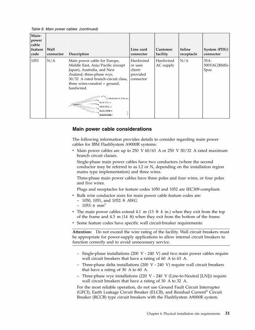
Table 9. Main power cables (continued)
Main-powercablefeaturecode
Wallconnector Description
Line cordconnector
Customerfacility
Inlinereceptacle
System (PDU)connector
1053 N/A Main power cable for Europe,Middle East, Asia/Pacific (exceptJapan), Australia, and NewZealand; three-phase wye,30/32 A rated branch-circuit class,three wires+neutral + ground,hardwired
Hardwiredor usesclient-providedconnector
HardwiredAC supply
N/A 35A-500VAC(RMS)-5pos
Main power cable considerations
The following information provides details to consider regarding main powercables for IBM FlashSystem A9000R systems:v Main power cables are up to 250 V 60/63 A or 250 V 30/32 A rated maximum
branch circuit classes.Single-phase main power cables have two conductors (where the secondconductor may be referred to as L2 or N, depending on the installation regionmains type implementation) and three wires.Three-phase main power cables have three poles and four wires, or four polesand five wires.Plugs and receptacles for feature codes 1050 and 1052 are IEC309-compliant.
v Bulk wire conductor sizes for main power cable feature codes are:– 1050, 1051, and 1052: 8 AWG– 1053: 6 mm2
v The main power cables extend 4.1 m (13 ft 4 in.) when they exit from the topof the frame and 4.3 m (14 ft) when they exit from the bottom of the frame.
v Some feature codes have specific wall circuit-breaker requirements:
Attention: Do not exceed the wire rating of the facility. Wall circuit breakers mustbe appropriate for power-supply applications to allow internal circuit breakers tofunction correctly and to avoid unnecessary service.
– Single-phase installations (200 V - 240 V) and two main power cables requirewall circuit breakers that have a rating of 60 A to 63 A.
– Three-phase delta installations (200 V - 240 V) require wall circuit breakersthat have a rating of 30 A to 60 A.
– Three-phase wye installations (220 V - 240 V (Line-to-Neutral [LN])) requirewall circuit breakers that have a rating of 30 A to 32 A.
For the most reliable operation, do not use Ground Fault Circuit Interrupter(GFCI), Earth Leakage Circuit Breaker (ELCB), and Residual Current® CircuitBreaker (RCCB) type circuit breakers with the FlashSystem A9000R system.
Chapter 4. Physical installation site requirements 31
The storage system is certified for safe operation and is compliant with IEC, EN,UL, CSA 60950-1 standards. However, if leakage detection circuit breakers arerequired by local electrical practice, the breakers must be sized for aleakage-current rating of 100 mA or greater to reduce the risk of server outagecaused by erroneous and spurious tripping. For more information, see “Leakagecurrent” on page xiv.
v Main power cables with the following feature codes must meet specific designcertifications:– 1050 and 1052 use bulk wire that meets UL and CSA safety agency
certifications, but not the EU harmonization certification.– 1051 and 1053 use bulk wire that meets the EU harmonization certification,
but not UL and CSA safety agency certifications.
Environmental requirementsEnsure that the installation site meets all operating environment requirements forthe IBM FlashSystem A9000R system.
Procedure
To ensure that the installation site meets the requirements, complete the followingsteps:1. Use adequate ventilation, especially during the first 120 days of continuous
operation. Ensure that there is an average room outdoor intake air rate of 0.4air change per hour.
2. Keep the front and rear of the rack clear of obstruction.3. Verify that you can meet the environmental operating requirements at the air
intake locations.4. Consider optimizing the air circulation and cooling for the rack by using a
raised floor, adjusting the floor layout, and adding perforated tiles around theair intake areas.The following sections cover the environmental requirements for yourFlashSystem A9000R system:v “Operating and shipping environment requirements”v “Air circulation and cooling” on page 33v “Contamination information” on page 35v “Acoustic declaration” on page 37v “Operating vibration requirements” on page 37
Operating and shipping environment requirementsYou must verify that your operating environment is compatible with the requiredspecifications.
With or without the rear-door heat exchanger option, the air that enters the frontdoor of the FlashSystem A9000R system must meet the following requirements.
Operating (powered on)v Temperature: 10 - 35°C (50 - 95°F)v Relative humidity: 20 - 80%, non-condensingv Maximum wet bulb temperature: 25°C (77°F)v Maximum altitude: 2134 m (7000 ft)
Non-operating (powered off)
32 IBM FlashSystem A9000R Models 9835-415 and 9837-415 Deployment Guide
v Temperature: 5 - 45°C (41 - 113°F)v Relative humidity: 20 - 80%, non-condensingv Maximum wet bulb temperature: 27°C (80.6°F)
Shipping v Temperature: -40 to 60°C (-40 to 140°F)v Relative humidity: 5 - 95%, non-condensingv Maximum wet bulb temperature: 29°C (84.2°F)
Important: A FlashSystem A9000R system that runs continuously must be withinthe specified operating environment.
A storage system can operate at the maximum allowable temperature for onlyshort durations, such as might occur during a disk drive module or power-supplyunit replacement.
Continuous operation above the maximum temperature increases the probability ofcomponent failure.
Air enters at the front of the rack and leaves at the back. To prevent the air that isleaving the rack from entering the intake of another piece of equipment, placeracks in alternate rows, in a back-to-back, and front-to-front arrangement.
Align the front of racks on a floor-tile seam, with a full line of perforated tilesimmediately in front of the rack.
System environmental acclimationCondensation is a normal and natural occurrence if packaging is removed at timeof delivery, during extreme cold weather delivery times.
All IBM equipment has been tested in climate chambers duplicating shippingtemperatures of - 40°C (- 40°F) to 60°C (140°F) and condensation and frost do notimpact reliability of the product.
It is highly recommended that the device not be removed from the shippingpackage for at least 24 hours, in order to acclimate to the new temperatureconditions. If there are still visible signs of condensation after the initial 24 hourwait period, acclimate the system without the shipping bag for an additional 12 -24 hours, or until no further visible condensation remains. If package materialremoval is necessary, equipment should be placed in a location away from any airvents.
Air circulation and coolingYou can take steps to optimize the air circulation and cooling for your IBMFlashSystem A9000R system.
Procedure
To optimize the cooling around your FlashSystem A9000R system, complete thefollowing steps:1. Install the FlashSystem A9000R system on a raised floor, which provides
increased air circulation for better cooling.For more information, see “Raised or non-raised floor considerations” on page20.
Chapter 4. Physical installation site requirements 33
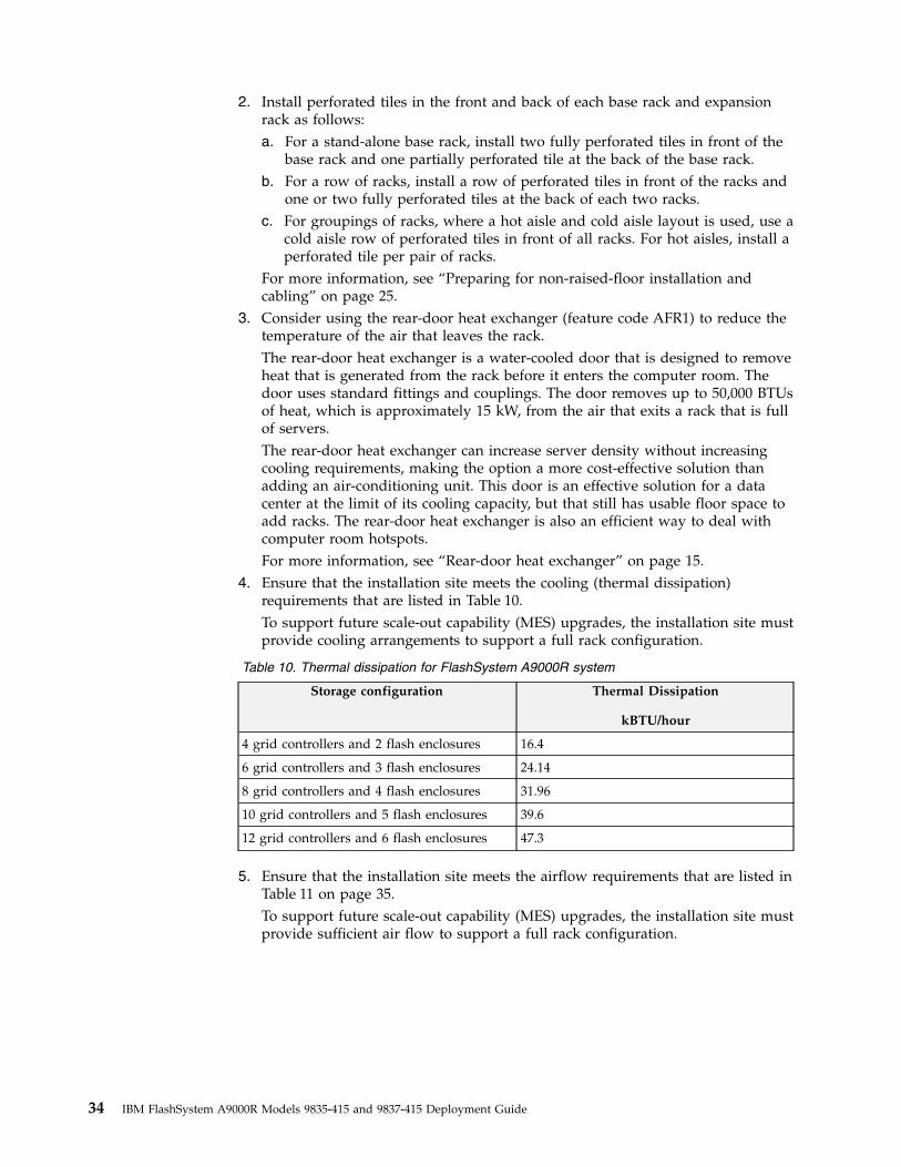
2. Install perforated tiles in the front and back of each base rack and expansionrack as follows:a. For a stand-alone base rack, install two fully perforated tiles in front of the
base rack and one partially perforated tile at the back of the base rack.b. For a row of racks, install a row of perforated tiles in front of the racks and
one or two fully perforated tiles at the back of each two racks.c. For groupings of racks, where a hot aisle and cold aisle layout is used, use a
cold aisle row of perforated tiles in front of all racks. For hot aisles, install aperforated tile per pair of racks.
For more information, see “Preparing for non-raised-floor installation andcabling” on page 25.
3. Consider using the rear-door heat exchanger (feature code AFR1) to reduce thetemperature of the air that leaves the rack.The rear-door heat exchanger is a water-cooled door that is designed to removeheat that is generated from the rack before it enters the computer room. Thedoor uses standard fittings and couplings. The door removes up to 50,000 BTUsof heat, which is approximately 15 kW, from the air that exits a rack that is fullof servers.The rear-door heat exchanger can increase server density without increasingcooling requirements, making the option a more cost-effective solution thanadding an air-conditioning unit. This door is an effective solution for a datacenter at the limit of its cooling capacity, but that still has usable floor space toadd racks. The rear-door heat exchanger is also an efficient way to deal withcomputer room hotspots.For more information, see “Rear-door heat exchanger” on page 15.
4. Ensure that the installation site meets the cooling (thermal dissipation)requirements that are listed in Table 10.To support future scale-out capability (MES) upgrades, the installation site mustprovide cooling arrangements to support a full rack configuration.
Table 10. Thermal dissipation for FlashSystem A9000R system
Storage configuration Thermal Dissipation
kBTU/hour
4 grid controllers and 2 flash enclosures 16.4
6 grid controllers and 3 flash enclosures 24.14
8 grid controllers and 4 flash enclosures 31.96
10 grid controllers and 5 flash enclosures 39.6
12 grid controllers and 6 flash enclosures 47.3
5. Ensure that the installation site meets the airflow requirements that are listed inTable 11 on page 35.To support future scale-out capability (MES) upgrades, the installation site mustprovide sufficient air flow to support a full rack configuration.
34 IBM FlashSystem A9000R Models 9835-415 and 9837-415 Deployment Guide
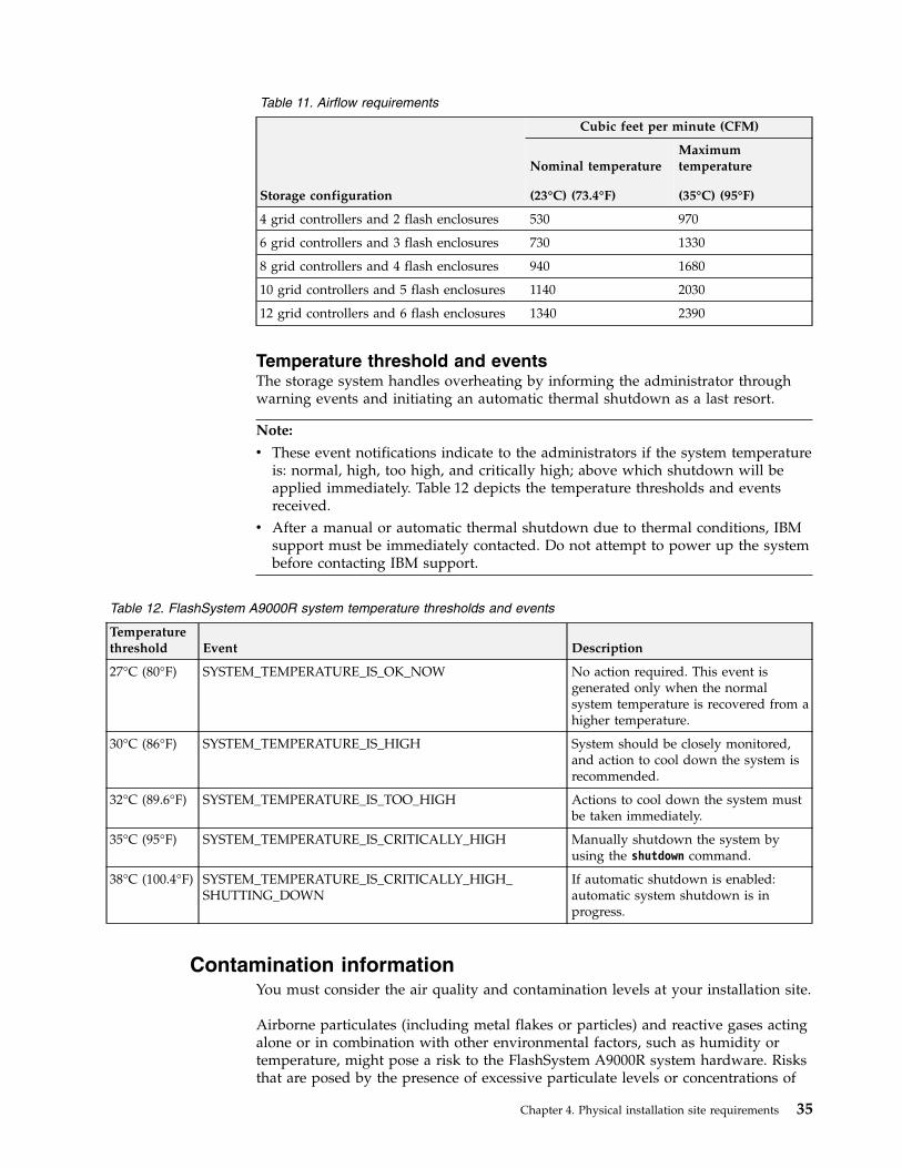
Table 11. Airflow requirements
Storage configuration
Cubic feet per minute (CFM)
Nominal temperature
(23°C) (73.4°F)
Maximumtemperature
(35°C) (95°F)
4 grid controllers and 2 flash enclosures 530 970
6 grid controllers and 3 flash enclosures 730 1330
8 grid controllers and 4 flash enclosures 940 1680
10 grid controllers and 5 flash enclosures 1140 2030
12 grid controllers and 6 flash enclosures 1340 2390
Temperature threshold and eventsThe storage system handles overheating by informing the administrator throughwarning events and initiating an automatic thermal shutdown as a last resort.
Note:
v These event notifications indicate to the administrators if the system temperatureis: normal, high, too high, and critically high; above which shutdown will beapplied immediately. Table 12 depicts the temperature thresholds and eventsreceived.
v After a manual or automatic thermal shutdown due to thermal conditions, IBMsupport must be immediately contacted. Do not attempt to power up the systembefore contacting IBM support.
Table 12. FlashSystem A9000R system temperature thresholds and events
Temperaturethreshold Event Description
27°C (80°F) SYSTEM_TEMPERATURE_IS_OK_NOW No action required. This event isgenerated only when the normalsystem temperature is recovered from ahigher temperature.
30°C (86°F) SYSTEM_TEMPERATURE_IS_HIGH System should be closely monitored,and action to cool down the system isrecommended.
32°C (89.6°F) SYSTEM_TEMPERATURE_IS_TOO_HIGH Actions to cool down the system mustbe taken immediately.
35°C (95°F) SYSTEM_TEMPERATURE_IS_CRITICALLY_HIGH Manually shutdown the system byusing the shutdown command.
38°C (100.4°F) SYSTEM_TEMPERATURE_IS_CRITICALLY_HIGH_SHUTTING_DOWN
If automatic shutdown is enabled:automatic system shutdown is inprogress.
Contamination informationYou must consider the air quality and contamination levels at your installation site.
Airborne particulates (including metal flakes or particles) and reactive gases actingalone or in combination with other environmental factors, such as humidity ortemperature, might pose a risk to the FlashSystem A9000R system hardware. Risksthat are posed by the presence of excessive particulate levels or concentrations of
Chapter 4. Physical installation site requirements 35
harmful gases include damage that might cause the FlashSystem A9000R system tomalfunction or cease functioning altogether. This specification describes limits forparticulates and gases that are intended to avoid such damage. The limits must notbe viewed or used as definitive limits because numerous other factors, such astemperature or moisture content of the air, can influence the impact of particulatesor environmental corrosives and gaseous contaminant transfer.
In the absence of specific limits, implement practices that maintain particulate orgas levels that are consistent with the protection of human health and safety. IfIBM determines that the levels of particulates or gases in your environmentdamaged the FlashSystem A9000R system, IBM might require implementation ofappropriate remedial measures to mitigate such environmental contaminationbefore providing repair or replacement of the FlashSystem A9000R system.Implementation of such remedial measures is a customer responsibility.
The following criteria must be met:
Gaseous contaminationSeverity level G1 as per ANSI/ISA 71.04-19851, which states that thereactivity rate of copper coupons must be less than 300 Angstroms permonth (Å/month, ≈ 0.0039 µg/cm2-hour weight gain) 2. In addition, thereactivity rate of silver coupons must be less than 300 Å/month (≈0.0035 µg/cm2-hour weight gain) 3. The reactive monitoring of gaseouscorrosibleness must be conducted approximately 5 cm (2 in.) in front ofthe rack on the air inlet side at one-quarter and three-quarter frame heightoff the floor. For environments with special air handling equipment thatalters the normal distribution of airflow into the rack, reactive monitoringof gaseous corrosibleness must be conducted at a location on the rackwhere air is entering at the highest rate.
Particulate contaminationData centers must meet the cleanliness level of ISO 14644-1 class 8. Fordata centers without air-side economizers, the ISO 14644-1 class 8cleanliness can be met by choosing one of the following filtration methods:v The room air can be continuously filtered with MERV 8 filters.v Air entering a data center can be filtered with MERV 11 or preferably
MERV 13 filters.
For data centers with air-side economizers, the choice of filters to achieveISO class 8 cleanliness depends on the specific conditions present at thatdata center. The deliquescence relative humidity of the particulatecontamination must be more than 60% RH 4. Data centers must be free ofzinc whiskers 5.
1. ANSI/ISA-71.04.1985. Environmental conditions for process measurement and control systems: Airborne contaminants. Instrument Societyof America, Research Triangle Park, NC, 1985.
2. The derivation of the equivalence between the rate of copper corrosion product thickness growth in Å/month and the rate ofweight gain assumes that Cu2S and Cu2O grow in equal proportions.
3. The derivation of the equivalence between the rate of silver corrosion product thickness growth in Å/month and the rate ofweight gain assumes that Ag2S is the only corrosion product.
4. The deliquescence relative humidity of particulate contamination is the relative humidity at which the dust absorbs enough waterto become wet and promote corrosion, ion migration, or both.
5. Surface debris is randomly collected from 10 areas of the data center on a 1.5 cm (0.6 in.) diameter disk of sticky, electricallyconductive tape on a metal stub. If examination of the sticky tape in a scanning electron microscope reveals no zinc whiskers, thedata center is considered free of zinc whiskers.
36 IBM FlashSystem A9000R Models 9835-415 and 9837-415 Deployment Guide
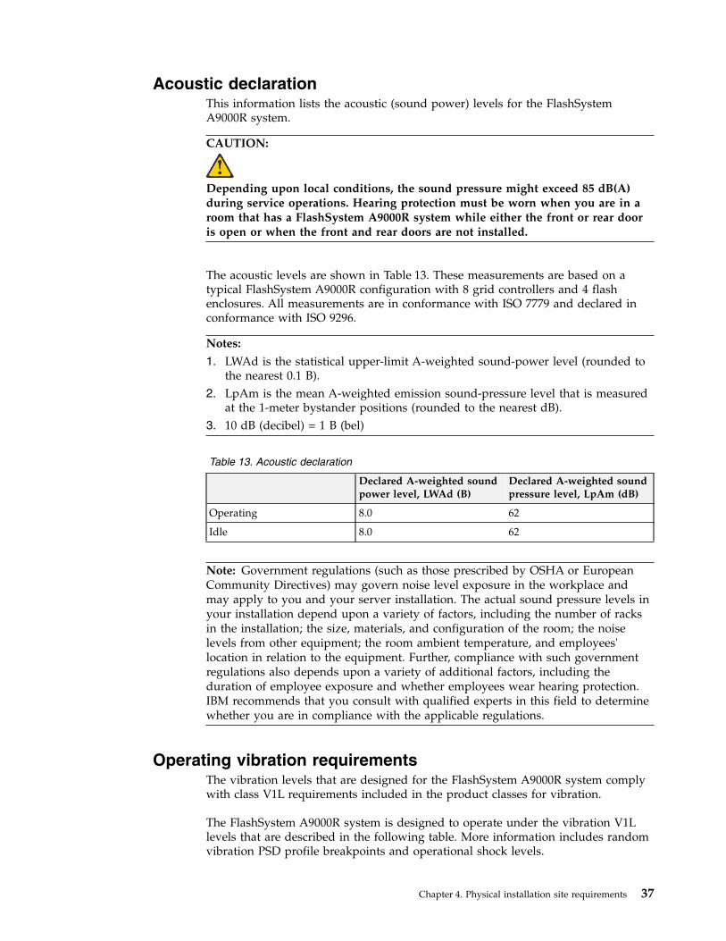
Acoustic declarationThis information lists the acoustic (sound power) levels for the FlashSystemA9000R system.
CAUTION:
Depending upon local conditions, the sound pressure might exceed 85 dB(A)during service operations. Hearing protection must be worn when you are in aroom that has a FlashSystem A9000R system while either the front or rear dooris open or when the front and rear doors are not installed.
The acoustic levels are shown in Table 13. These measurements are based on atypical FlashSystem A9000R configuration with 8 grid controllers and 4 flashenclosures. All measurements are in conformance with ISO 7779 and declared inconformance with ISO 9296.
Notes:
1. LWAd is the statistical upper-limit A-weighted sound-power level (rounded tothe nearest 0.1 B).
2. LpAm is the mean A-weighted emission sound-pressure level that is measuredat the 1-meter bystander positions (rounded to the nearest dB).
3. 10 dB (decibel) = 1 B (bel)
Table 13. Acoustic declaration
Declared A-weighted soundpower level, LWAd (B)
Declared A-weighted soundpressure level, LpAm (dB)
Operating 8.0 62
Idle 8.0 62
Note: Government regulations (such as those prescribed by OSHA or EuropeanCommunity Directives) may govern noise level exposure in the workplace andmay apply to you and your server installation. The actual sound pressure levels inyour installation depend upon a variety of factors, including the number of racksin the installation; the size, materials, and configuration of the room; the noiselevels from other equipment; the room ambient temperature, and employees'location in relation to the equipment. Further, compliance with such governmentregulations also depends upon a variety of additional factors, including theduration of employee exposure and whether employees wear hearing protection.IBM recommends that you consult with qualified experts in this field to determinewhether you are in compliance with the applicable regulations.
Operating vibration requirementsThe vibration levels that are designed for the FlashSystem A9000R system complywith class V1L requirements included in the product classes for vibration.
The FlashSystem A9000R system is designed to operate under the vibration V1Llevels that are described in the following table. More information includes randomvibration PSD profile breakpoints and operational shock levels.
Chapter 4. Physical installation site requirements 37
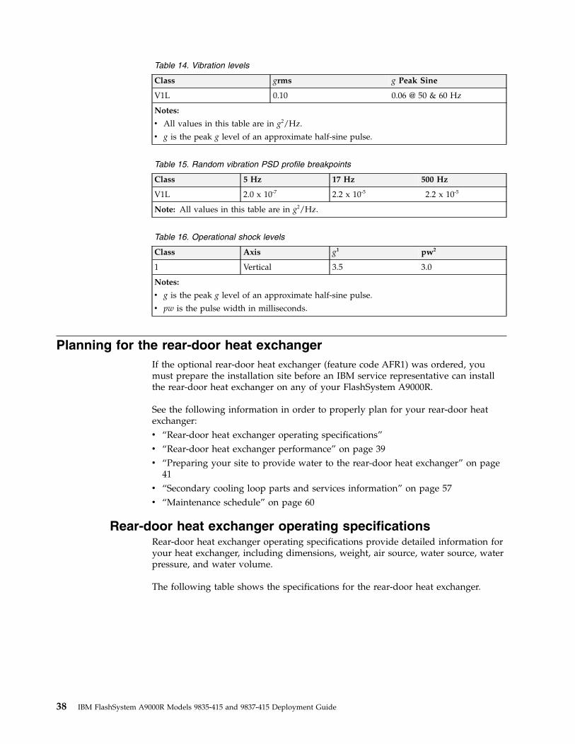
Table 14. Vibration levels
Class grms g Peak Sine
V1L 0.10 0.06 @ 50 & 60 Hz
Notes:
v All values in this table are in g2/Hz.
v g is the peak g level of an approximate half-sine pulse.
Table 15. Random vibration PSD profile breakpoints
Class 5 Hz 17 Hz 500 Hz
V1L 2.0 x 10⁻⁷ 2.2 x 10⁻⁵ 2.2 x 10⁻⁵
Note: All values in this table are in g2/Hz.
Table 16. Operational shock levels
Class Axis g1 pw2
1 Vertical 3.5 3.0
Notes:
v g is the peak g level of an approximate half-sine pulse.
v pw is the pulse width in milliseconds.
Planning for the rear-door heat exchangerIf the optional rear-door heat exchanger (feature code AFR1) was ordered, youmust prepare the installation site before an IBM service representative can installthe rear-door heat exchanger on any of your FlashSystem A9000R.
See the following information in order to properly plan for your rear-door heatexchanger:v “Rear-door heat exchanger operating specifications”v “Rear-door heat exchanger performance” on page 39v “Preparing your site to provide water to the rear-door heat exchanger” on page
41v “Secondary cooling loop parts and services information” on page 57v “Maintenance schedule” on page 60
Rear-door heat exchanger operating specificationsRear-door heat exchanger operating specifications provide detailed information foryour heat exchanger, including dimensions, weight, air source, water source, waterpressure, and water volume.
The following table shows the specifications for the rear-door heat exchanger.
38 IBM FlashSystem A9000R Models 9835-415 and 9837-415 Deployment Guide
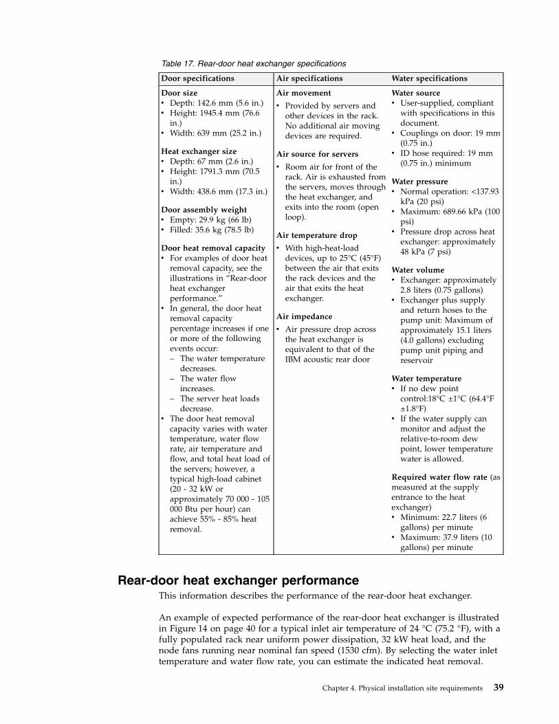
Table 17. Rear-door heat exchanger specifications
Door specifications Air specifications Water specifications
Door sizev Depth: 142.6 mm (5.6 in.)v Height: 1945.4 mm (76.6
in.)v Width: 639 mm (25.2 in.)
Heat exchanger sizev Depth: 67 mm (2.6 in.)v Height: 1791.3 mm (70.5
in.)v Width: 438.6 mm (17.3 in.)
Door assembly weightv Empty: 29.9 kg (66 lb)v Filled: 35.6 kg (78.5 lb)
Door heat removal capacityv For examples of door heat
removal capacity, see theillustrations in “Rear-doorheat exchangerperformance.”
v In general, the door heatremoval capacitypercentage increases if oneor more of the followingevents occur:– The water temperature
decreases.– The water flow
increases.– The server heat loads
decrease.v The door heat removal
capacity varies with watertemperature, water flowrate, air temperature andflow, and total heat load ofthe servers; however, atypical high-load cabinet(20 - 32 kW orapproximately 70 000 - 105000 Btu per hour) canachieve 55% - 85% heatremoval.
Air movement
v Provided by servers andother devices in the rack.No additional air movingdevices are required.
Air source for servers
v Room air for front of therack. Air is exhausted fromthe servers, moves throughthe heat exchanger, andexits into the room (openloop).
Air temperature drop
v With high-heat-loaddevices, up to 25°C (45°F)between the air that exitsthe rack devices and theair that exits the heatexchanger.
Air impedance
v Air pressure drop acrossthe heat exchanger isequivalent to that of theIBM acoustic rear door
Water sourcev User-supplied, compliant
with specifications in thisdocument.
v Couplings on door: 19 mm(0.75 in.)
v ID hose required: 19 mm(0.75 in.) minimum
Water pressurev Normal operation: <137.93
kPa (20 psi)v Maximum: 689.66 kPa (100
psi)v Pressure drop across heat
exchanger: approximately48 kPa (7 psi)
Water volumev Exchanger: approximately
2.8 liters (0.75 gallons)v Exchanger plus supply
and return hoses to thepump unit: Maximum ofapproximately 15.1 liters(4.0 gallons) excludingpump unit piping andreservoir
Water temperaturev If no dew point
control:18°C ±1°C (64.4°F±1.8°F)
v If the water supply canmonitor and adjust therelative-to-room dewpoint, lower temperaturewater is allowed.
Required water flow rate (asmeasured at the supplyentrance to the heatexchanger)v Minimum: 22.7 liters (6
gallons) per minutev Maximum: 37.9 liters (10
gallons) per minute
Rear-door heat exchanger performanceThis information describes the performance of the rear-door heat exchanger.
An example of expected performance of the rear-door heat exchanger is illustratedin Figure 14 on page 40 for a typical inlet air temperature of 24 °C (75.2 °F), with afully populated rack near uniform power dissipation, 32 kW heat load, and thenode fans running near nominal fan speed (1530 cfm). By selecting the water inlettemperature and water flow rate, you can estimate the indicated heat removal.
Chapter 4. Physical installation site requirements 39
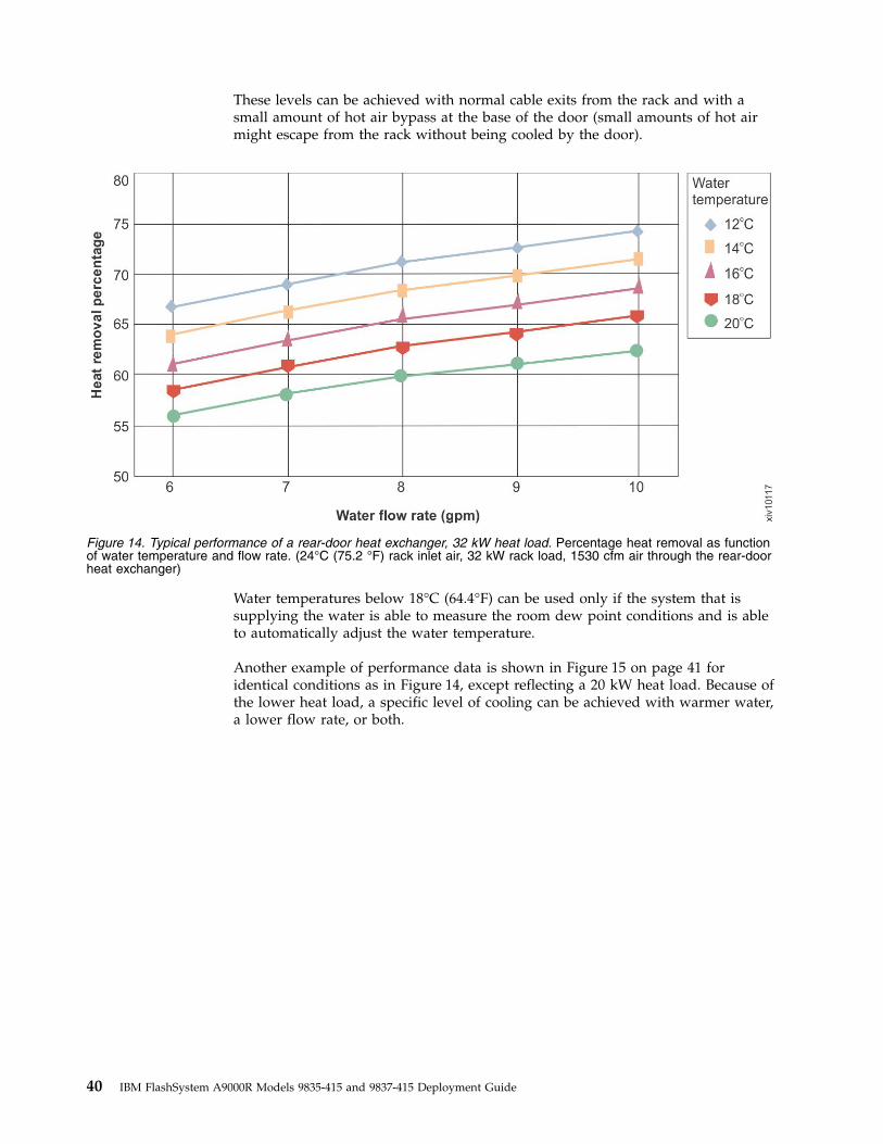
These levels can be achieved with normal cable exits from the rack and with asmall amount of hot air bypass at the base of the door (small amounts of hot airmight escape from the rack without being cooled by the door).
Water temperatures below 18°C (64.4°F) can be used only if the system that issupplying the water is able to measure the room dew point conditions and is ableto automatically adjust the water temperature.
Another example of performance data is shown in Figure 15 on page 41 foridentical conditions as in Figure 14, except reflecting a 20 kW heat load. Because ofthe lower heat load, a specific level of cooling can be achieved with warmer water,a lower flow rate, or both.
Figure 14. Typical performance of a rear-door heat exchanger, 32 kW heat load. Percentage heat removal as functionof water temperature and flow rate. (24°C (75.2 °F) rack inlet air, 32 kW rack load, 1530 cfm air through the rear-doorheat exchanger)
40 IBM FlashSystem A9000R Models 9835-415 and 9837-415 Deployment Guide
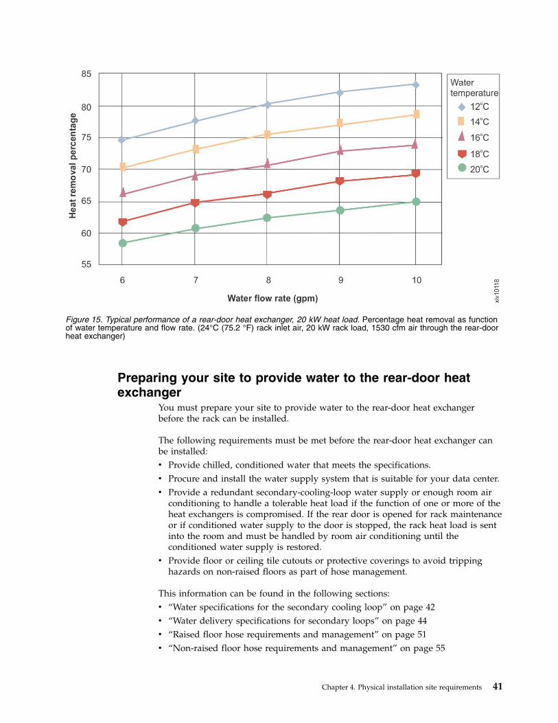
Preparing your site to provide water to the rear-door heatexchanger
You must prepare your site to provide water to the rear-door heat exchangerbefore the rack can be installed.
The following requirements must be met before the rear-door heat exchanger canbe installed:v Provide chilled, conditioned water that meets the specifications.v Procure and install the water supply system that is suitable for your data center.v Provide a redundant secondary-cooling-loop water supply or enough room air
conditioning to handle a tolerable heat load if the function of one or more of theheat exchangers is compromised. If the rear door is opened for rack maintenanceor if conditioned water supply to the door is stopped, the rack heat load is sentinto the room and must be handled by room air conditioning until theconditioned water supply is restored.
v Provide floor or ceiling tile cutouts or protective coverings to avoid trippinghazards on non-raised floors as part of hose management.
This information can be found in the following sections:v “Water specifications for the secondary cooling loop” on page 42v “Water delivery specifications for secondary loops” on page 44v “Raised floor hose requirements and management” on page 51v “Non-raised floor hose requirements and management” on page 55
Figure 15. Typical performance of a rear-door heat exchanger, 20 kW heat load. Percentage heat removal as functionof water temperature and flow rate. (24°C (75.2 °F) rack inlet air, 20 kW rack load, 1530 cfm air through the rear-doorheat exchanger)
Chapter 4. Physical installation site requirements 41
Water specifications for the secondary cooling loopIn order to avoid system failures, it is important to follow the water specificationrequirements for the secondary cooling loop of your rear-door heat exchanger.
The water that is being supplied to the heat exchanger must meet the followingrequirements; otherwise, system failures might occur over time, as a result of:v Leaks that are caused by corrosion and pitting of the metal components of the
heat exchanger or the water supply system.v Buildup of scale deposits inside the heat exchanger, which can cause the
following problems:– A reduction of the ability of the heat exchanger to cool the air that is
exhausted from the rack.– Failure of mechanical hardware, such as a hose quick-connect adapter.
v Organic contamination, such as bacteria, fungi, or algae. This contamination cancause the same problems as described for scale deposits.
Water control and conditioning for the secondary cooling loop
The water that is used to fill, refill, and supply the heat exchanger must beparticle-free deionized water or particle-free distilled water with appropriatecontrols for avoiding the following issues:v Metal corrosionv Bacterial foulingv Scaling
Because of typical water temperatures (described in “Preparing your site toprovide water to the rear-door heat exchanger” on page 41), the water might notbe able to originate from the primary building chilled-water system. Conditionedwater for the heat exchanger must be supplied as part of a secondary, closed-loopsystem.
Important: Do not use glycol solutions because they can adversely affect thecooling performance of the heat exchanger.
Materials for the secondary cooling loops
You can use any of the following materials in supply lines, connectors, manifolds,pumps, hoses, and any other hardware that makes up the closed-loopwater-supply system at your location:v Copperv Brass with less than 30% zinc contentv Stainless steel – 303, 304, or 316v Ethylene Propylene Diene Monomer (EPDM) rubber, peroxide cured, non-metal
oxide
Materials to avoid in secondary loops
Do not use any of the following materials in any part of your water supply system.v Oxidizing biocides (such as, chlorine, bromine, and chlorine dioxide)v Aluminumv Brass with greater than 30% zincv Irons (non-stainless steel)
42 IBM FlashSystem A9000R Models 9835-415 and 9837-415 Deployment Guide
Water supply requirements for secondary cooling loops
Ensure that the following requirements are met for the system that supplies thechilled conditioned water to the heat exchanger.
Temperature
The heat exchanger, supply hose, and return hoses are not insulated anddo not have features that are designed to address the creation andcollection water from condensate. Avoid any condition that might causecondensation. The temperature of the water inside the supply hose, returnhose, and the heat exchanger must be kept above the dew point of thelocation where the heat exchanger is being used.
Attention: Typical primary chilled water is too cold for use in this applicationbecause building chilled water can be as cold as 4°C - 6°C (39°F - 43°F).
Important: If the system that supplies the cooling water is not able to measure theroom dew point and automatically adjust the water temperature, the minimumwater temperature that must be maintained is 18°C±1°C (64.4°F±1.8°F). Theminimum water temperature is consistent with the ASHRAE Class 1Environmental Specification that requires a maximum dew point of 17°C (62.6°F).See the ASHRAE document Thermal Guidelines for Data Processing Environments.You can find information about obtaining this document on the ASHRAE website(www.ashrae.org/home/search?k=Thermal%20Guidelines%20for%20Data%20Processing%20Environments).
Pressure
The water pressure in the secondary loop must be less than 689.66 kPa (100psi). Normal operating pressure at the heat exchanger must be 137.93 kPa(20 psi) or less.
Flow rate
The flow rate of the water in the system must be in the range of 23 - 38liters (6 - 10 gallons) per minute.
Pressure drop versus flow rate for heat exchangers (includingquick-connect couplings) is defined as approximately 48 kPa (7 psi) at 30liters (8 gallons) per minute.
Water volume limits
The heat exchangers hold 2.8 - 5.3 liters (0.75 - 1.4 gallons). 15 meters (50ft) of 19 mm (0.75-in.) supply and return hoses hold approximately 9.4liters (2.5 gallons). To minimize exposure to flooding in the event of leaks,the entire cooling system (heat exchanger, supply hose, and return hose)excluding any reservoir tank must have a maximum 15.1 liters (4 gallons)of water. This is a cautionary statement not a functional requirement. Also,consider using leak detection methods on the secondary loop that supplieswater to the heat exchanger.
Air exposure
The secondary cooling loop is a closed loop, with no continuous exposureto room air. After you fill the loop, remove all air from the loop. Air bleedvalves are provided at the top of each heat exchanger manifold for purgingall air from the system.
Chapter 4. Physical installation site requirements 43
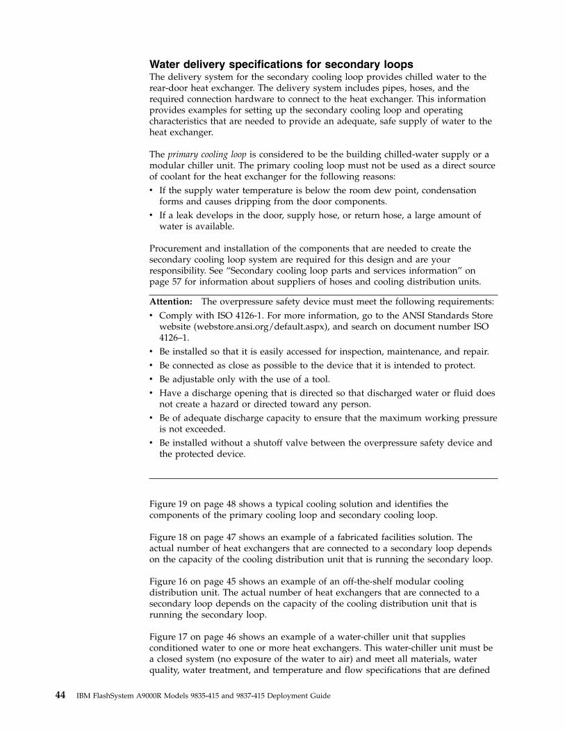
Water delivery specifications for secondary loopsThe delivery system for the secondary cooling loop provides chilled water to therear-door heat exchanger. The delivery system includes pipes, hoses, and therequired connection hardware to connect to the heat exchanger. This informationprovides examples for setting up the secondary cooling loop and operatingcharacteristics that are needed to provide an adequate, safe supply of water to theheat exchanger.
The primary cooling loop is considered to be the building chilled-water supply or amodular chiller unit. The primary cooling loop must not be used as a direct sourceof coolant for the heat exchanger for the following reasons:v If the supply water temperature is below the room dew point, condensation
forms and causes dripping from the door components.v If a leak develops in the door, supply hose, or return hose, a large amount of
water is available.
Procurement and installation of the components that are needed to create thesecondary cooling loop system are required for this design and are yourresponsibility. See “Secondary cooling loop parts and services information” onpage 57 for information about suppliers of hoses and cooling distribution units.
Attention: The overpressure safety device must meet the following requirements:
v Comply with ISO 4126-1. For more information, go to the ANSI Standards Storewebsite (webstore.ansi.org/default.aspx), and search on document number ISO4126–1.
v Be installed so that it is easily accessed for inspection, maintenance, and repair.v Be connected as close as possible to the device that it is intended to protect.v Be adjustable only with the use of a tool.v Have a discharge opening that is directed so that discharged water or fluid does
not create a hazard or directed toward any person.v Be of adequate discharge capacity to ensure that the maximum working pressure
is not exceeded.v Be installed without a shutoff valve between the overpressure safety device and
the protected device.
Figure 19 on page 48 shows a typical cooling solution and identifies thecomponents of the primary cooling loop and secondary cooling loop.
Figure 18 on page 47 shows an example of a fabricated facilities solution. Theactual number of heat exchangers that are connected to a secondary loop dependson the capacity of the cooling distribution unit that is running the secondary loop.
Figure 16 on page 45 shows an example of an off-the-shelf modular coolingdistribution unit. The actual number of heat exchangers that are connected to asecondary loop depends on the capacity of the cooling distribution unit that isrunning the secondary loop.
Figure 17 on page 46 shows an example of a water-chiller unit that suppliesconditioned water to one or more heat exchangers. This water-chiller unit must bea closed system (no exposure of the water to air) and meet all materials, waterquality, water treatment, and temperature and flow specifications that are defined
44 IBM FlashSystem A9000R Models 9835-415 and 9837-415 Deployment Guide
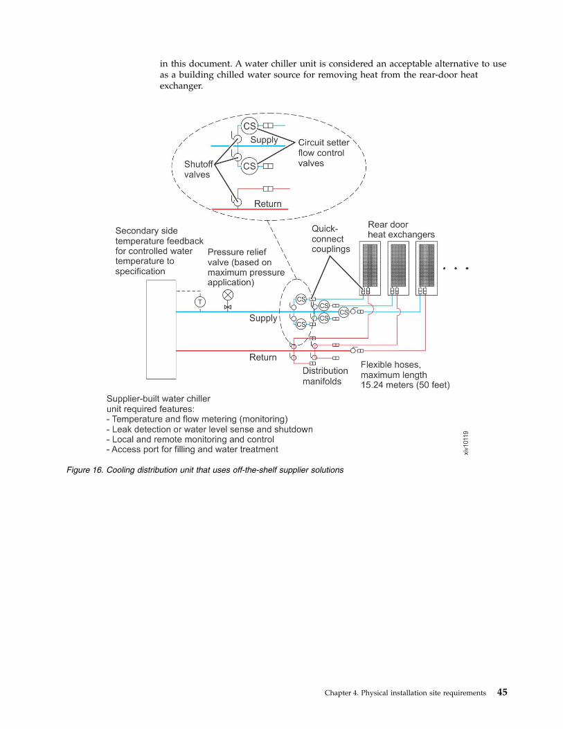
in this document. A water chiller unit is considered an acceptable alternative to useas a building chilled water source for removing heat from the rear-door heatexchanger.
Figure 16. Cooling distribution unit that uses off-the-shelf supplier solutions
Chapter 4. Physical installation site requirements 45
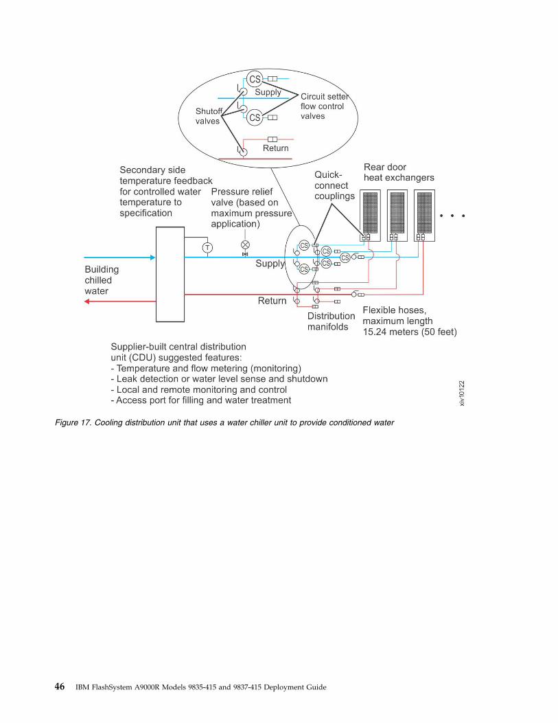
Figure 17. Cooling distribution unit that uses a water chiller unit to provide conditioned water
46 IBM FlashSystem A9000R Models 9835-415 and 9837-415 Deployment Guide
Figure 18. Cooling distribution unit that uses a fabricated facilities solution
Chapter 4. Physical installation site requirements 47
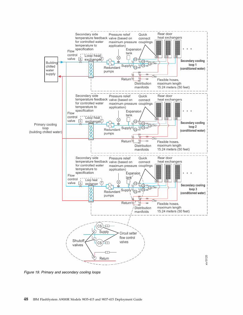
Figure 19. Primary and secondary cooling loops
48 IBM FlashSystem A9000R Models 9835-415 and 9837-415 Deployment Guide
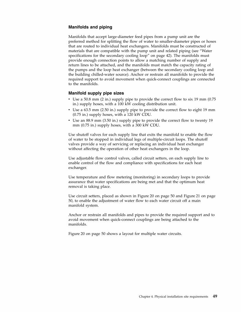
Manifolds and piping
Manifolds that accept large-diameter feed pipes from a pump unit are thepreferred method for splitting the flow of water to smaller-diameter pipes or hosesthat are routed to individual heat exchangers. Manifolds must be constructed ofmaterials that are compatible with the pump unit and related piping (see “Waterspecifications for the secondary cooling loop” on page 42). The manifolds mustprovide enough connection points to allow a matching number of supply andreturn lines to be attached, and the manifolds must match the capacity rating ofthe pumps and the loop heat exchanger (between the secondary cooling loop andthe building chilled-water source). Anchor or restrain all manifolds to provide therequired support to avoid movement when quick-connect couplings are connectedto the manifolds.
Manifold supply pipe sizesv Use a 50.8 mm (2 in.) supply pipe to provide the correct flow to six 19 mm (0.75
in.) supply hoses, with a 100 kW cooling distribution unit.v Use a 63.5 mm (2.50 in.) supply pipe to provide the correct flow to eight 19 mm
(0.75 in.) supply hoses, with a 120 kW CDU.v Use an 88.9 mm (3.50 in.) supply pipe to provide the correct flow to twenty 19
mm (0.75 in.) supply hoses, with a 300 kW CDU.
Use shutoff valves for each supply line that exits the manifold to enable the flowof water to be stopped in individual legs of multiple-circuit loops. The shutoffvalves provide a way of servicing or replacing an individual heat exchangerwithout affecting the operation of other heat exchangers in the loop.
Use adjustable flow control valves, called circuit setters, on each supply line toenable control of the flow and compliance with specifications for each heatexchanger.
Use temperature and flow metering (monitoring) in secondary loops to provideassurance that water specifications are being met and that the optimum heatremoval is taking place.
Use circuit setters, placed as shown in Figure 20 on page 50 and Figure 21 on page50, to enable the adjustment of water flow to each water circuit off a mainmanifold system.
Anchor or restrain all manifolds and pipes to provide the required support and toavoid movement when quick-connect couplings are being attached to themanifolds.
Figure 20 on page 50 shows a layout for multiple water circuits.
Chapter 4. Physical installation site requirements 49
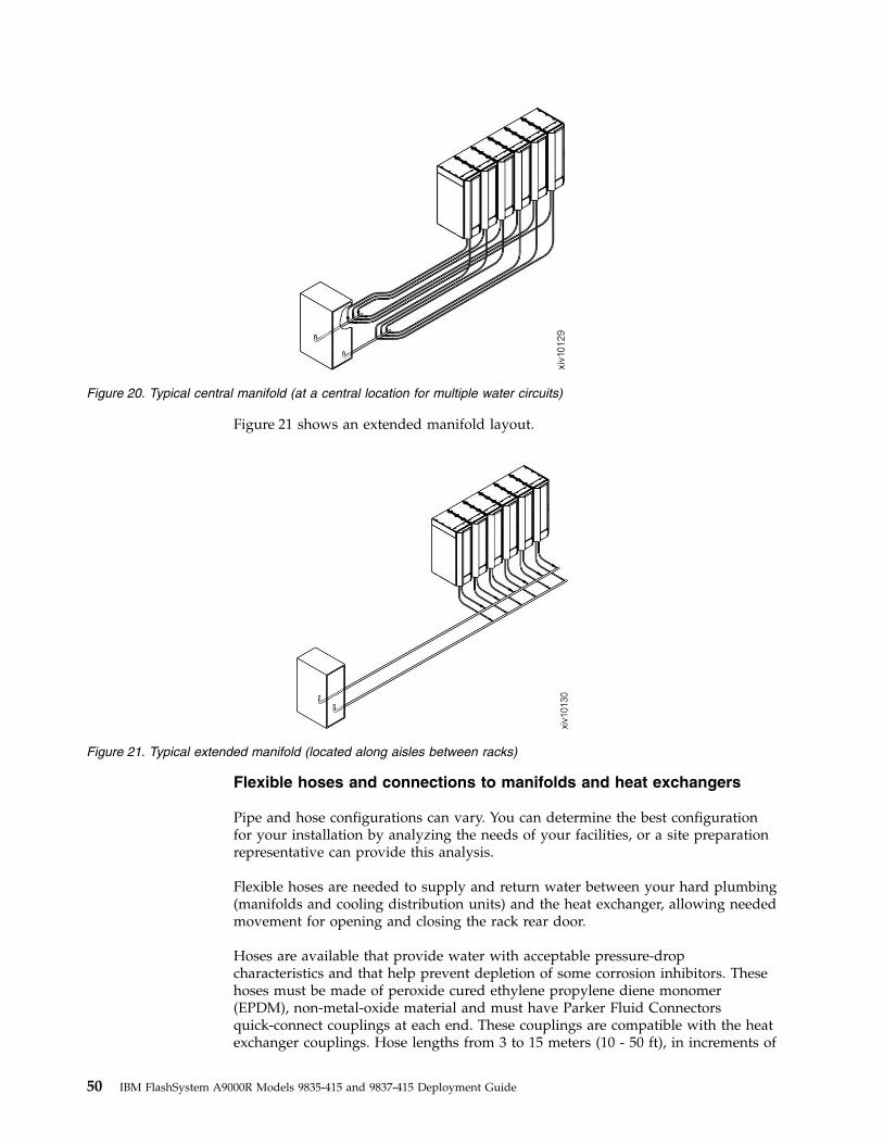
Figure 21 shows an extended manifold layout.
Flexible hoses and connections to manifolds and heat exchangers
Pipe and hose configurations can vary. You can determine the best configurationfor your installation by analyzing the needs of your facilities, or a site preparationrepresentative can provide this analysis.
Flexible hoses are needed to supply and return water between your hard plumbing(manifolds and cooling distribution units) and the heat exchanger, allowing neededmovement for opening and closing the rack rear door.
Hoses are available that provide water with acceptable pressure-dropcharacteristics and that help prevent depletion of some corrosion inhibitors. Thesehoses must be made of peroxide cured ethylene propylene diene monomer(EPDM), non-metal-oxide material and must have Parker Fluid Connectorsquick-connect couplings at each end. These couplings are compatible with the heatexchanger couplings. Hose lengths from 3 to 15 meters (10 - 50 ft), in increments of
Figure 20. Typical central manifold (at a central location for multiple water circuits)
Figure 21. Typical extended manifold (located along aisles between racks)
50 IBM FlashSystem A9000R Models 9835-415 and 9837-415 Deployment Guide
3 meters (10 ft), are available. Hoses that are longer than 15 meters (50 ft) mightcreate unacceptable pressure loss in the secondary circuit and reduce the waterflow, reducing the heat removal capabilities of the heat exchanger.
For information about a supplier of these hoses, see “Secondary cooling loop partsand services information” on page 57. Use solid piping or tubing that has aminimum inner diameter of 19 mm (0.75 in.) and the fewest possible jointsbetween a manifold and a heat exchanger in each secondary loop.
You can use quick-connect couplings to attach the hoses to the distributionmanifolds. You must use quick-connect couplings to attach the hoses to the heatexchanger. Hose couplings that connect to the heat exchanger must have thefollowing characteristics:v The couplings must be constructed of passivated 300-L series stainless steel or
brass with less than 30% zinc content. The coupling size is 19 mm (0.75 in.).v The supply hose must have a Parker (male) quick-coupling nipple, part number
SH6-63-W, or equivalent. The return hose must have a Parker (female)quick-connect coupling, part number SH6-62-W, or equivalent.
v At the opposite (manifold) end of the hoses, use similar quick-connect couplings.However, if you want to use other types of connectors, make sure that positivelocking mechanisms are used to prevent loss of water when the hoses aredisconnected. The connections must minimize water spill and air inclusion intothe system when they are disconnected. You can also permanently attach hosesto the manifolds by using barbed fittings and clamps.
Raised floor hose requirements and managementOn a raised floor, hoses can be routed under the floor tiles and can be brought upfrom beneath the rack through special tile cutouts. The hoses are connected to thequick-connect couplings on the bottom of the heat exchanger.
In a typical example, each heat exchanger requires a special cut 0.6 m × 0.6 m (2 ft× 2 ft) floor tile below it with the opening outside of the rack footprint. A portionof the tile is cut away and correctly covered to protect against sharp edges. Thecorner opening is placed directly under the hinge side of the rack rear door. Theopening size of the cut is 152.4 mm wide × 190.5 mm long ±12.7 mm (6.0 in. wide× 7.5 in. long ±0.5 in.) in the direction parallel to the door. See Figure 22 on page52 and Figure 23 on page 53.
Chapter 4. Physical installation site requirements 51
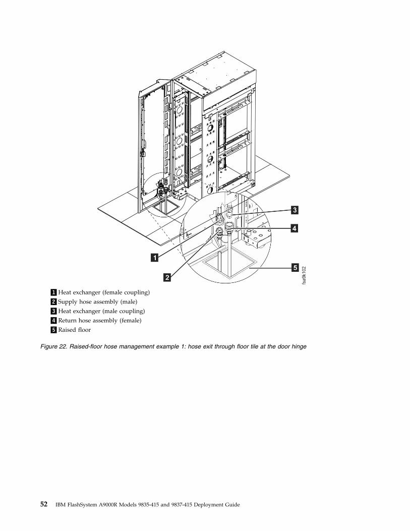
▌1▐Heat exchanger (female coupling)
▌2▐Supply hose assembly (male)
▌3▐Heat exchanger (male coupling)
▌4▐Return hose assembly (female)
▌5▐Raised floor
Figure 22. Raised-floor hose management example 1: hose exit through floor tile at the door hinge
52 IBM FlashSystem A9000R Models 9835-415 and 9837-415 Deployment Guide
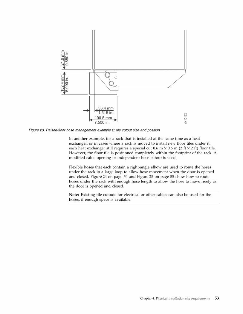
In another example, for a rack that is installed at the same time as a heatexchanger, or in cases where a rack is moved to install new floor tiles under it,each heat exchanger still requires a special cut 0.6 m × 0.6 m (2 ft × 2 ft) floor tile.However, the floor tile is positioned completely within the footprint of the rack. Amodified cable opening or independent hose cutout is used.
Flexible hoses that each contain a right-angle elbow are used to route the hosesunder the rack in a large loop to allow hose movement when the door is openedand closed. Figure 24 on page 54 and Figure 25 on page 55 show how to routehoses under the rack with enough hose length to allow the hose to move freely asthe door is opened and closed.
Note: Existing tile cutouts for electrical or other cables can also be used for thehoses, if enough space is available.
Figure 23. Raised-floor hose management example 2: tile cutout size and position
Chapter 4. Physical installation site requirements 53
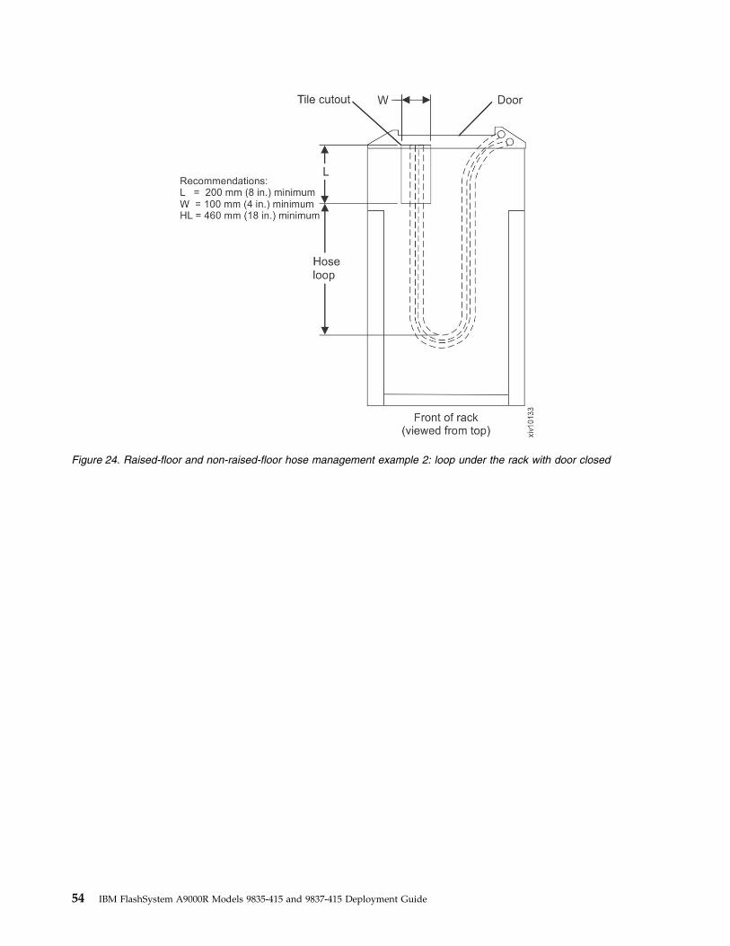
Figure 24. Raised-floor and non-raised-floor hose management example 2: loop under the rack with door closed
54 IBM FlashSystem A9000R Models 9835-415 and 9837-415 Deployment Guide
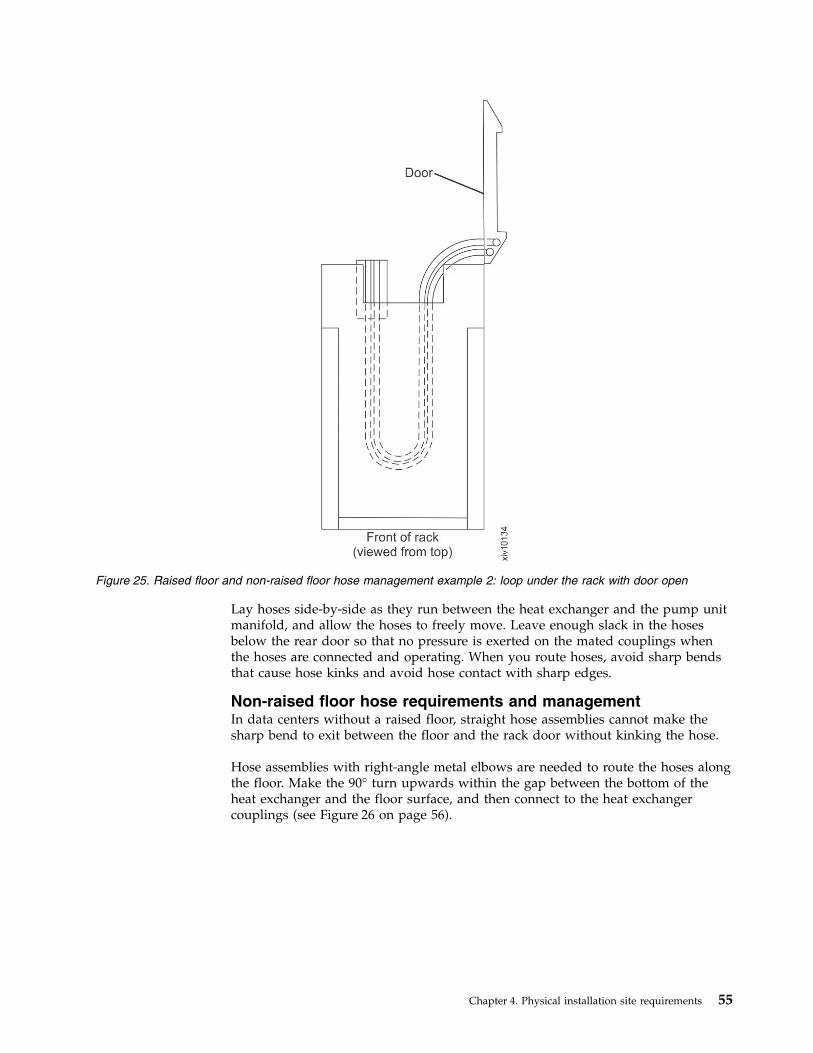
Lay hoses side-by-side as they run between the heat exchanger and the pump unitmanifold, and allow the hoses to freely move. Leave enough slack in the hosesbelow the rear door so that no pressure is exerted on the mated couplings whenthe hoses are connected and operating. When you route hoses, avoid sharp bendsthat cause hose kinks and avoid hose contact with sharp edges.
Non-raised floor hose requirements and managementIn data centers without a raised floor, straight hose assemblies cannot make thesharp bend to exit between the floor and the rack door without kinking the hose.
Hose assemblies with right-angle metal elbows are needed to route the hoses alongthe floor. Make the 90° turn upwards within the gap between the bottom of theheat exchanger and the floor surface, and then connect to the heat exchangercouplings (see Figure 26 on page 56).
Figure 25. Raised floor and non-raised floor hose management example 2: loop under the rack with door open
Chapter 4. Physical installation site requirements 55
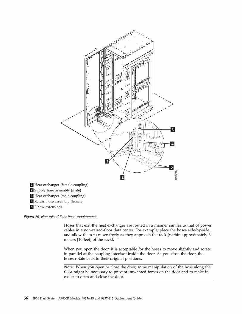
Hoses that exit the heat exchanger are routed in a manner similar to that of powercables in a non-raised-floor data center. For example, place the hoses side-by-sideand allow them to move freely as they approach the rack (within approximately 3meters [10 feet] of the rack).
When you open the door, it is acceptable for the hoses to move slightly and rotatein parallel at the coupling interface inside the door. As you close the door, thehoses rotate back to their original positions.
Note: When you open or close the door, some manipulation of the hose along thefloor might be necessary to prevent unwanted forces on the door and to make iteasier to open and close the door.
▌1▐Heat exchanger (female coupling)
▌2▐Supply hose assembly (male)
▌3▐Heat exchanger (male coupling)
▌4▐Return hose assembly (female)
▌5▐Elbow extensions
Figure 26. Non-raised floor hose requirements
56 IBM FlashSystem A9000R Models 9835-415 and 9837-415 Deployment Guide
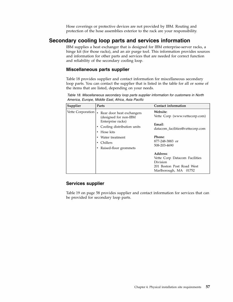
Hose coverings or protective devices are not provided by IBM. Routing andprotection of the hose assemblies exterior to the rack are your responsibility.
Secondary cooling loop parts and services informationIBM supplies a heat exchanger that is designed for IBM enterprise-server racks, ahinge kit (for those racks), and an air purge tool. This information provides sourcesand information for other parts and services that are needed for correct functionand reliability of the secondary cooling loop.
Miscellaneous parts supplier
Table 18 provides supplier and contact information for miscellaneous secondaryloop parts. You can contact the supplier that is listed in the table for all or some ofthe items that are listed, depending on your needs.
Table 18. Miscellaneous secondary loop parts supplier information for customers in NorthAmerica, Europe, Middle East, Africa, Asia Pacific
Supplier Parts Contact information
Vette Corporation v Rear door heat exchangers(designed for non-IBMEnterprise racks)
v Cooling distribution units
v Hose kits
v Water treatment
v Chillers
v Raised-floor grommets
Website:Vette Corp (www.vettecorp.com)
Email:[email protected]
Phone:877-248-3883 or508-203-4690
Address:Vette Corp Datacom FacilitiesDivision201 Boston Post Road WestMarlborough, MA 01752
Services supplier
Table 19 on page 58 provides supplier and contact information for services that canbe provided for secondary loop parts.
Chapter 4. Physical installation site requirements 57
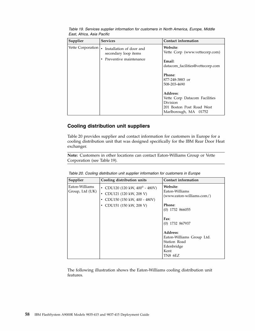
Table 19. Services supplier information for customers in North America, Europe, MiddleEast, Africa, Asia Pacific
Supplier Services Contact information
Vette Corporation v Installation of door andsecondary loop items
v Preventive maintenance
Website:Vette Corp (www.vettecorp.com)
Email:[email protected]
Phone:877-248-3883 or508-203-4690
Address:Vette Corp Datacom FacilitiesDivision201 Boston Post Road WestMarlborough, MA 01752
Cooling distribution unit suppliers
Table 20 provides supplier and contact information for customers in Europe for acooling distribution unit that was designed specifically for the IBM Rear Door Heatexchanger.
Note: Customers in other locations can contact Eaton-Williams Group or VetteCorporation (see Table 19).
Table 20. Cooling distribution unit supplier information for customers in Europe
Supplier Cooling distribution units Contact information
Eaton-WilliamsGroup, Ltd (UK)
v CDU120 (120 kW, 400® - 480V)
v CDU121 (120 kW, 208 V)
v CDU150 (150 kW, 400 - 480V)
v CDU151 (150 kW, 208 V)
Website:Eaton-Williams(www.eaton-williams.com/)
Phone:(0) 1732 866055
Fax:(0) 1732 867937
Address:Eaton-Williams Group Ltd.Station RoadEdenbridgeKentTN8 6EZ
The following illustration shows the Eaton-Williams cooling distribution unitfeatures.
58 IBM FlashSystem A9000R Models 9835-415 and 9837-415 Deployment Guide
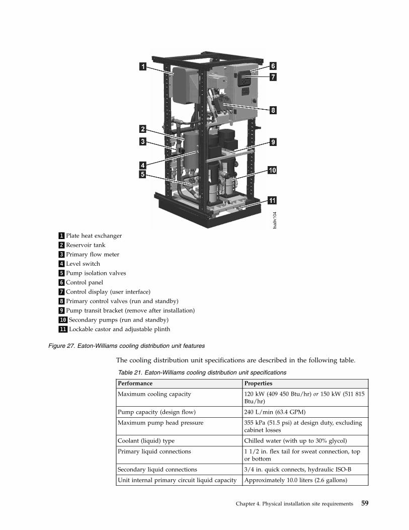
The cooling distribution unit specifications are described in the following table.
Table 21. Eaton-Williams cooling distribution unit specifications
Performance Properties
Maximum cooling capacity 120 kW (409 450 Btu/hr) or 150 kW (511 815Btu/hr)
Pump capacity (design flow) 240 L/min (63.4 GPM)
Maximum pump head pressure 355 kPa (51.5 psi) at design duty, excludingcabinet losses
Coolant (liquid) type Chilled water (with up to 30% glycol)
Primary liquid connections 1 1/2 in. flex tail for sweat connection, topor bottom
Secondary liquid connections 3/4 in. quick connects, hydraulic ISO-B
Unit internal primary circuit liquid capacity Approximately 10.0 liters (2.6 gallons)
▌1▐Plate heat exchanger
▌2▐Reservoir tank
▌3▐Primary flow meter
▌4▐Level switch
▌5▐Pump isolation valves
▌6▐Control panel
▌7▐Control display (user interface)
▌8▐Primary control valves (run and standby)
▌9▐Pump transit bracket (remove after installation)
▌10▐Secondary pumps (run and standby)
▌11▐Lockable castor and adjustable plinth
Figure 27. Eaton-Williams cooling distribution unit features
Chapter 4. Physical installation site requirements 59
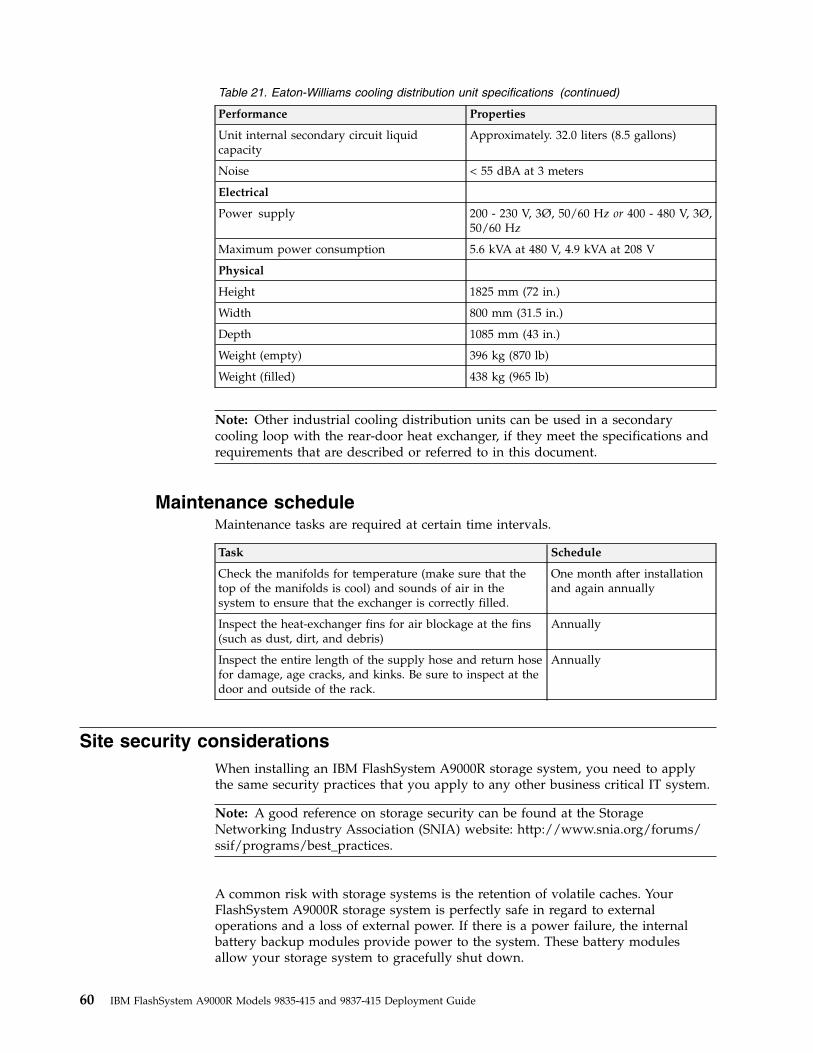
Table 21. Eaton-Williams cooling distribution unit specifications (continued)
Performance Properties
Unit internal secondary circuit liquidcapacity
Approximately. 32.0 liters (8.5 gallons)
Noise < 55 dBA at 3 meters
Electrical
Power supply 200 - 230 V, 3Ø, 50/60 Hz or 400 - 480 V, 3Ø,50/60 Hz
Maximum power consumption 5.6 kVA at 480 V, 4.9 kVA at 208 V
Physical
Height 1825 mm (72 in.)
Width 800 mm (31.5 in.)
Depth 1085 mm (43 in.)
Weight (empty) 396 kg (870 lb)
Weight (filled) 438 kg (965 lb)
Note: Other industrial cooling distribution units can be used in a secondarycooling loop with the rear-door heat exchanger, if they meet the specifications andrequirements that are described or referred to in this document.
Maintenance scheduleMaintenance tasks are required at certain time intervals.
Task Schedule
Check the manifolds for temperature (make sure that thetop of the manifolds is cool) and sounds of air in thesystem to ensure that the exchanger is correctly filled.
One month after installationand again annually
Inspect the heat-exchanger fins for air blockage at the fins(such as dust, dirt, and debris)
Annually
Inspect the entire length of the supply hose and return hosefor damage, age cracks, and kinks. Be sure to inspect at thedoor and outside of the rack.
Annually
Site security considerationsWhen installing an IBM FlashSystem A9000R storage system, you need to applythe same security practices that you apply to any other business critical IT system.
Note: A good reference on storage security can be found at the StorageNetworking Industry Association (SNIA) website: http://www.snia.org/forums/ssif/programs/best_practices.
A common risk with storage systems is the retention of volatile caches. YourFlashSystem A9000R storage system is perfectly safe in regard to externaloperations and a loss of external power. If there is a power failure, the internalbattery backup modules provide power to the system. These battery modulesallow your storage system to gracefully shut down.
60 IBM FlashSystem A9000R Models 9835-415 and 9837-415 Deployment Guide

If desired, you can install your own uninterruptible power supply (UPS) unit(s) orgenerators in order to provide further power-failure protection.
However, if someone gains physical access to the equipment, that person mightmanually shut off components by bypassing the preferred process. In this case, thestorage system is likely to lose the contents of its volatile caches, resulting in a dataloss and system unavailability.
To eliminate or greatly reduce this risk, the IBM FlashSystem A9000R rack can beequipped with lockable doors (feature code AFR6).
Important: Protect your storage system by locking the rack doors and monitoringphysical access to the equipment.
Chapter 4. Physical installation site requirements 61

62 IBM FlashSystem A9000R Models 9835-415 and 9837-415 Deployment Guide
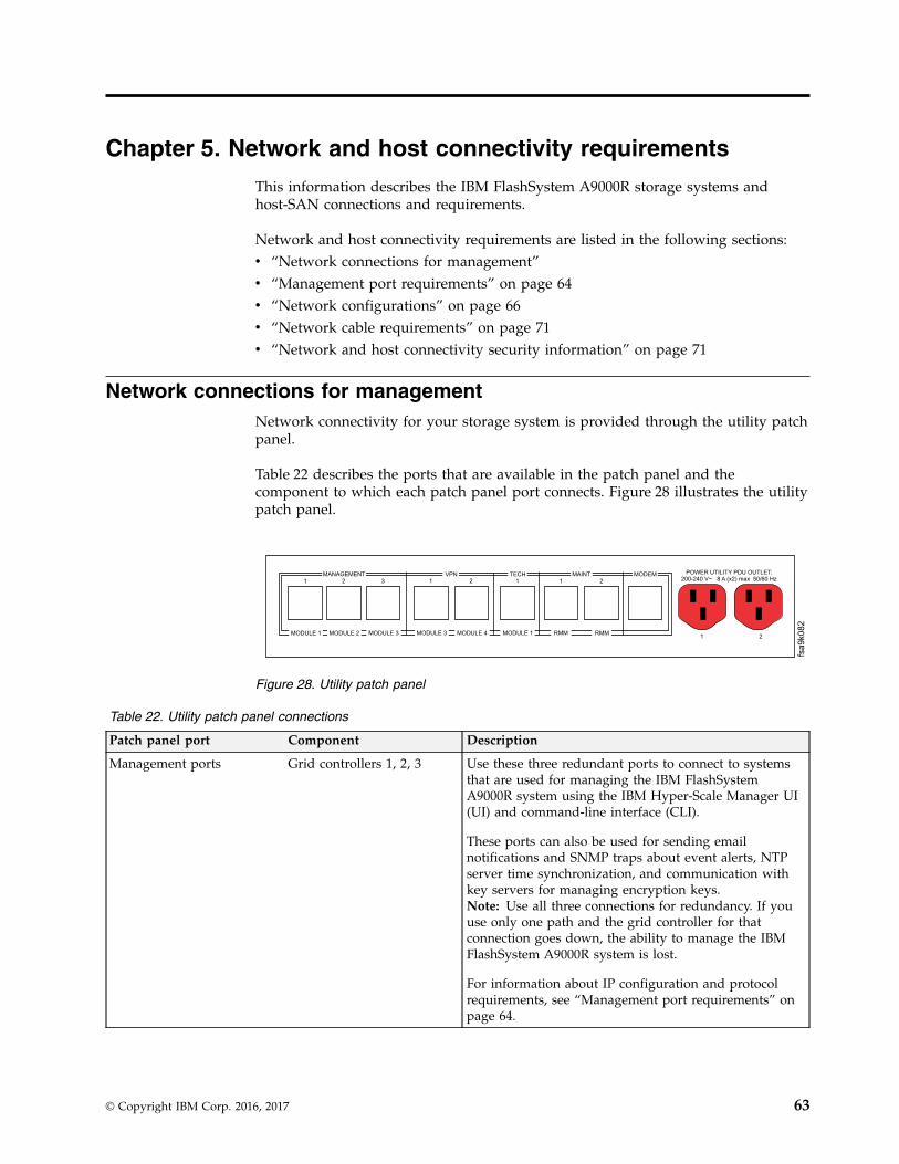
Chapter 5. Network and host connectivity requirements
This information describes the IBM FlashSystem A9000R storage systems andhost-SAN connections and requirements.
Network and host connectivity requirements are listed in the following sections:v “Network connections for management”v “Management port requirements” on page 64v “Network configurations” on page 66v “Network cable requirements” on page 71v “Network and host connectivity security information” on page 71
Network connections for managementNetwork connectivity for your storage system is provided through the utility patchpanel.
Table 22 describes the ports that are available in the patch panel and thecomponent to which each patch panel port connects. Figure 28 illustrates the utilitypatch panel.
Table 22. Utility patch panel connections
Patch panel port Component Description
Management ports Grid controllers 1, 2, 3 Use these three redundant ports to connect to systemsthat are used for managing the IBM FlashSystemA9000R system using the IBM Hyper-Scale Manager UI(UI) and command-line interface (CLI).
These ports can also be used for sending emailnotifications and SNMP traps about event alerts, NTPserver time synchronization, and communication withkey servers for managing encryption keys.Note: Use all three connections for redundancy. If youuse only one path and the grid controller for thatconnection goes down, the ability to manage the IBMFlashSystem A9000R system is lost.
For information about IP configuration and protocolrequirements, see “Management port requirements” onpage 64.
MANAGEMENT VPN TECH MAINT MODEM
MODULE 1 MODULE 2 MODULE 3 MODULE 3 MODULE 4 MODULE 1 RMM RMM
POWER UTILITY PDU OUTLET:
200-240 V~ 8 A (x2) max 50/60 Hz1 2 3 1 1 12 2
1 2
fsa9k082
Figure 28. Utility patch panel
© Copyright IBM Corp. 2016, 2017 63
Table 22. Utility patch panel connections (continued)
Patch panel port Component Description
VPN (remote support) ports Grid controllers 3, 4 These two virtual private network (VPN) ports are usedto connect to the IBM FlashSystem Remote SupportCenter.
Note: Use both VPN connections for redundancy toavoid losing remote support if one of the gridcontrollers fails.
Tech (technician) ports Grid controller 1 (For technician use only.) This port is used by the IBMservice representative to connect a notebook computerto the storage system, for initial configuration andservicing the system.
A Dynamic Host Configuration Protocol (DHCP) serveris implemented over this port. The DHCP serverautomatically assigns IP addresses to the notebookcomputer and establishes a connection to the IBMFlashSystem A9000R system.
Note: There is a second identical technician port on thefront of the rack, next to the power button. Thistechnician port connects to grid controller 2.
Maint (maintenancemodule) ports
Maintenance module (For technician use only.) These two ports connectdirectly to the maintenance module.
Modem port Modem (For technician use only.) Use this port to connect amodem for remote support.
Management port requirementsThe management ports provide the connectivity required for IBM Hyper-ScaleManager, IBM FlashSystem A9000R command-line interface (CLI), and othermanagement tools to monitor and control the IBM FlashSystem A9000R system.
IP configuration
The IBM FlashSystem A9000R storage system has three redundant managementport IP addresses, over Ethernet interfaces, in case of failure.
Each IP address is handled by different grid controllers in the initial grid elementconfiguration. It is recommended that the IBM Hyper-Scale Manager and CLI beconfigured with all three IP addresses that are defined for IBM FlashSystemA9000R for high availability. For more information about the IBM Hyper-ScaleManager, see IBM Hyper-Scale Manager User Guide (SC27-8560) on the IBMFlashSystem A9000R Knowledge Center website (ibm.com/support/knowledgecenter/STJKN5)
Management functions can be performed through any of the IP addresses. Theseaddresses can be accessed simultaneously by multiple clients.
For each of the three management ports, the customer or technical assistant mustprovide the following information to the IBM service representative before startingthe installation process:v IP address of the portv Net mask
64 IBM FlashSystem A9000R Models 9835-415 and 9837-415 Deployment Guide
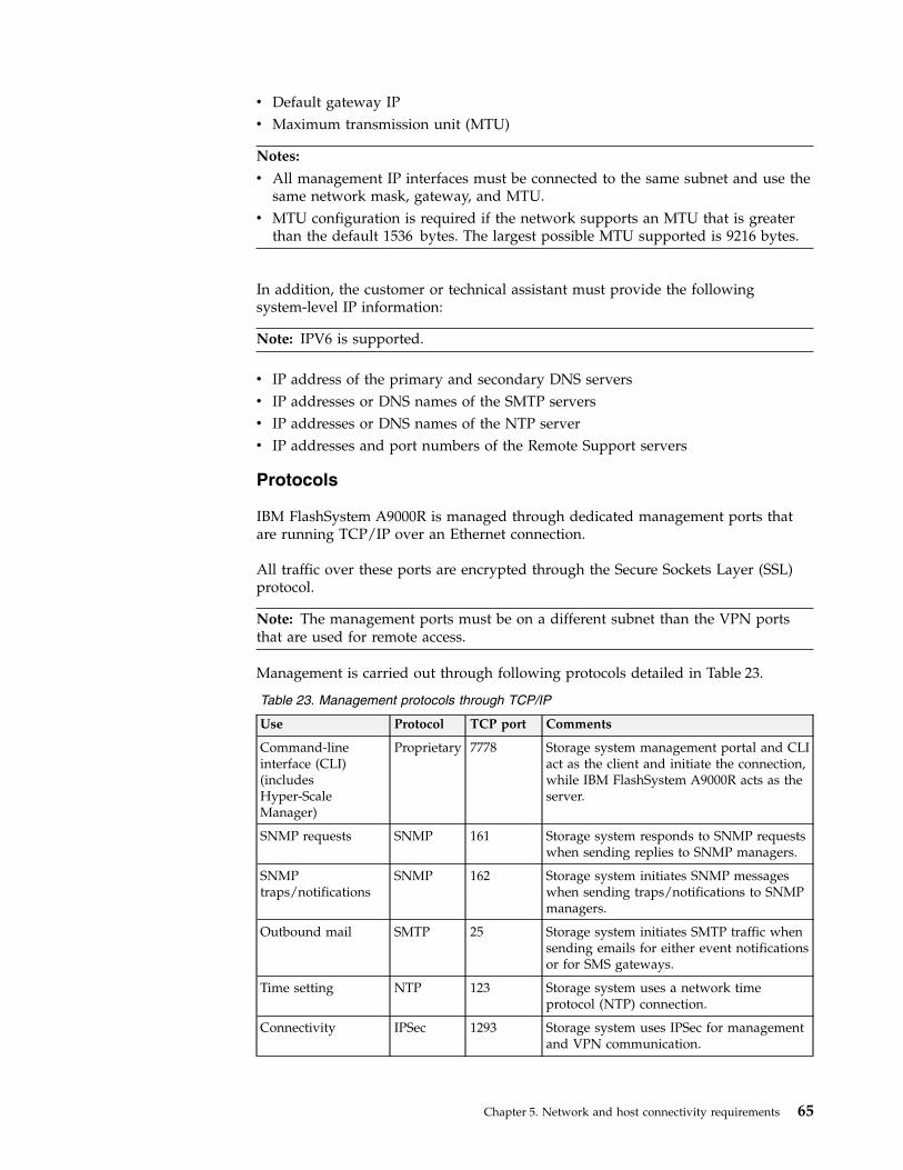
v Default gateway IPv Maximum transmission unit (MTU)
Notes:
v All management IP interfaces must be connected to the same subnet and use thesame network mask, gateway, and MTU.
v MTU configuration is required if the network supports an MTU that is greaterthan the default 1536 bytes. The largest possible MTU supported is 9216 bytes.
In addition, the customer or technical assistant must provide the followingsystem-level IP information:
Note: IPV6 is supported.
v IP address of the primary and secondary DNS serversv IP addresses or DNS names of the SMTP serversv IP addresses or DNS names of the NTP serverv IP addresses and port numbers of the Remote Support servers
Protocols
IBM FlashSystem A9000R is managed through dedicated management ports thatare running TCP/IP over an Ethernet connection.
All traffic over these ports are encrypted through the Secure Sockets Layer (SSL)protocol.
Note: The management ports must be on a different subnet than the VPN portsthat are used for remote access.
Management is carried out through following protocols detailed in Table 23.
Table 23. Management protocols through TCP/IP
Use Protocol TCP port Comments
Command-lineinterface (CLI)(includesHyper-ScaleManager)
Proprietary 7778 Storage system management portal and CLIact as the client and initiate the connection,while IBM FlashSystem A9000R acts as theserver.
SNMP requests SNMP 161 Storage system responds to SNMP requestswhen sending replies to SNMP managers.
SNMPtraps/notifications
SNMP 162 Storage system initiates SNMP messageswhen sending traps/notifications to SNMPmanagers.
Outbound mail SMTP 25 Storage system initiates SMTP traffic whensending emails for either event notificationsor for SMS gateways.
Time setting NTP 123 Storage system uses a network timeprotocol (NTP) connection.
Connectivity IPSec 1293 Storage system uses IPSec for managementand VPN communication.
Chapter 5. Network and host connectivity requirements 65
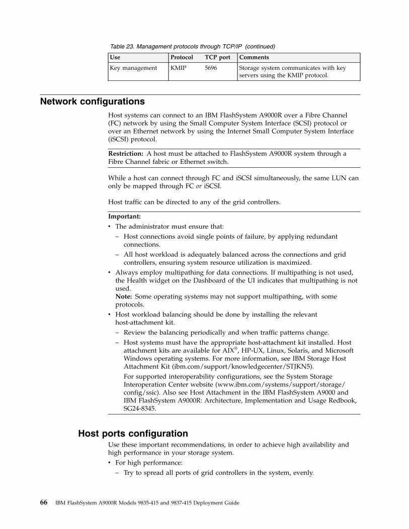
Table 23. Management protocols through TCP/IP (continued)
Use Protocol TCP port Comments
Key management KMIP 5696 Storage system communicates with keyservers using the KMIP protocol.
Network configurationsHost systems can connect to an IBM FlashSystem A9000R over a Fibre Channel(FC) network by using the Small Computer System Interface (SCSI) protocol orover an Ethernet network by using the Internet Small Computer System Interface(iSCSI) protocol.
Restriction: A host must be attached to FlashSystem A9000R system through aFibre Channel fabric or Ethernet switch.
While a host can connect through FC and iSCSI simultaneously, the same LUN canonly be mapped through FC or iSCSI.
Host traffic can be directed to any of the grid controllers.
Important:
v The administrator must ensure that:– Host connections avoid single points of failure, by applying redundant
connections.– All host workload is adequately balanced across the connections and grid
controllers, ensuring system resource utilization is maximized.v Always employ multipathing for data connections. If multipathing is not used,
the Health widget on the Dashboard of the UI indicates that multipathing is notused.Note: Some operating systems may not support multipathing, with someprotocols.
v Host workload balancing should be done by installing the relevanthost-attachment kit.– Review the balancing periodically and when traffic patterns change.– Host systems must have the appropriate host-attachment kit installed. Host
attachment kits are available for AIX®, HP-UX, Linux, Solaris, and MicrosoftWindows operating systems. For more information, see IBM Storage HostAttachment Kit (ibm.com/support/knowledgecenter/STJKN5).For supported interoperability configurations, see the System StorageInteroperation Center website (www.ibm.com/systems/support/storage/config/ssic). Also see Host Attachment in the IBM FlashSystem A9000 andIBM FlashSystem A9000R: Architecture, Implementation and Usage Redbook,SG24-8345.
Host ports configurationUse these important recommendations, in order to achieve high availability andhigh performance in your storage system.v For high performance:
– Try to spread all ports of grid controllers in the system, evenly.
66 IBM FlashSystem A9000R Models 9835-415 and 9837-415 Deployment Guide
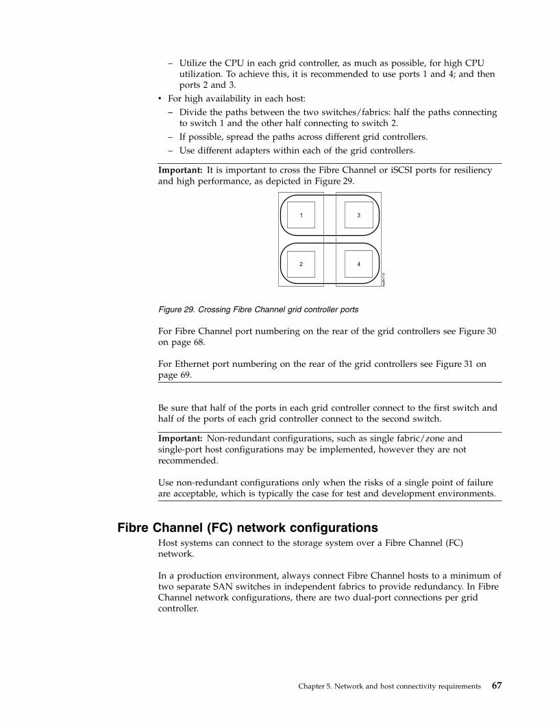
– Utilize the CPU in each grid controller, as much as possible, for high CPUutilization. To achieve this, it is recommended to use ports 1 and 4; and thenports 2 and 3.
v For high availability in each host:– Divide the paths between the two switches/fabrics: half the paths connecting
to switch 1 and the other half connecting to switch 2.– If possible, spread the paths across different grid controllers.– Use different adapters within each of the grid controllers.
Important: It is important to cross the Fibre Channel or iSCSI ports for resiliencyand high performance, as depicted in Figure 29.
1
2
3
4
fsa
9k11
0
Figure 29. Crossing Fibre Channel grid controller ports
For Fibre Channel port numbering on the rear of the grid controllers see Figure 30on page 68.
For Ethernet port numbering on the rear of the grid controllers see Figure 31 onpage 69.
Be sure that half of the ports in each grid controller connect to the first switch andhalf of the ports of each grid controller connect to the second switch.
Important: Non-redundant configurations, such as single fabric/zone andsingle-port host configurations may be implemented, however they are notrecommended.
Use non-redundant configurations only when the risks of a single point of failureare acceptable, which is typically the case for test and development environments.
Fibre Channel (FC) network configurationsHost systems can connect to the storage system over a Fibre Channel (FC)network.
In a production environment, always connect Fibre Channel hosts to a minimum oftwo separate SAN switches in independent fabrics to provide redundancy. In FibreChannel network configurations, there are two dual-port connections per gridcontroller.
Chapter 5. Network and host connectivity requirements 67
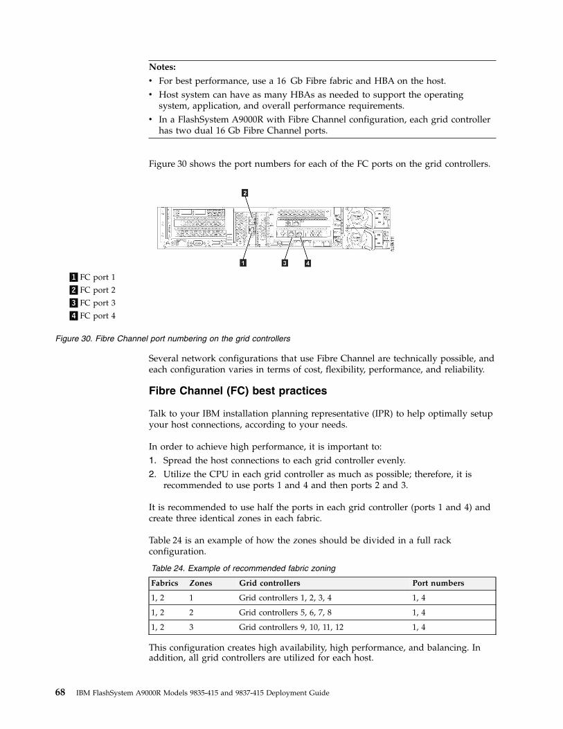
Notes:
v For best performance, use a 16 Gb Fibre fabric and HBA on the host.v Host system can have as many HBAs as needed to support the operating
system, application, and overall performance requirements.v In a FlashSystem A9000R with Fibre Channel configuration, each grid controller
has two dual 16 Gb Fibre Channel ports.
Figure 30 shows the port numbers for each of the FC ports on the grid controllers.
Several network configurations that use Fibre Channel are technically possible, andeach configuration varies in terms of cost, flexibility, performance, and reliability.
Fibre Channel (FC) best practices
Talk to your IBM installation planning representative (IPR) to help optimally setupyour host connections, according to your needs.
In order to achieve high performance, it is important to:1. Spread the host connections to each grid controller evenly.2. Utilize the CPU in each grid controller as much as possible; therefore, it is
recommended to use ports 1 and 4 and then ports 2 and 3.
It is recommended to use half the ports in each grid controller (ports 1 and 4) andcreate three identical zones in each fabric.
Table 24 is an example of how the zones should be divided in a full rackconfiguration.
Table 24. Example of recommended fabric zoning
Fabrics Zones Grid controllers Port numbers
1, 2 1 Grid controllers 1, 2, 3, 4 1, 4
1, 2 2 Grid controllers 5, 6, 7, 8 1, 4
1, 2 3 Grid controllers 9, 10, 11, 12 1, 4
This configuration creates high availability, high performance, and balancing. Inaddition, all grid controllers are utilized for each host.
▌1▐FC port 1
▌2▐FC port 2
▌3▐FC port 3
▌4▐FC port 4
Figure 30. Fibre Channel port numbering on the grid controllers
68 IBM FlashSystem A9000R Models 9835-415 and 9837-415 Deployment Guide
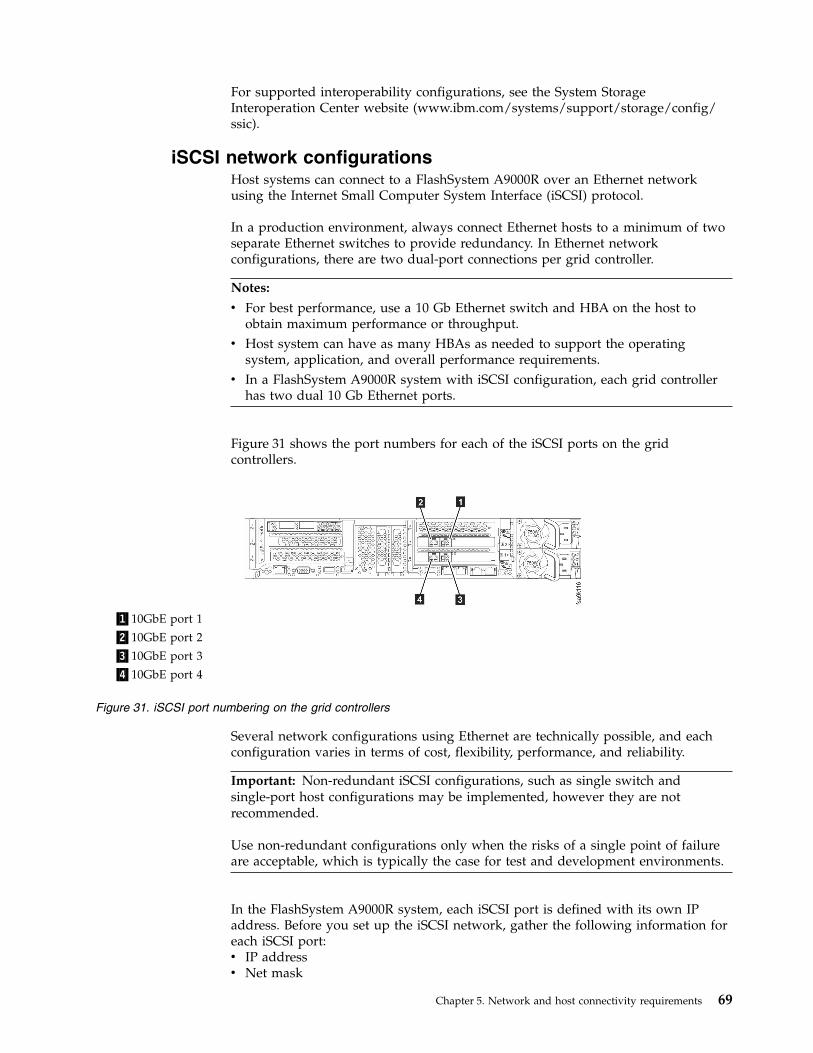
For supported interoperability configurations, see the System StorageInteroperation Center website (www.ibm.com/systems/support/storage/config/ssic).
iSCSI network configurationsHost systems can connect to a FlashSystem A9000R over an Ethernet networkusing the Internet Small Computer System Interface (iSCSI) protocol.
In a production environment, always connect Ethernet hosts to a minimum of twoseparate Ethernet switches to provide redundancy. In Ethernet networkconfigurations, there are two dual-port connections per grid controller.
Notes:
v For best performance, use a 10 Gb Ethernet switch and HBA on the host toobtain maximum performance or throughput.
v Host system can have as many HBAs as needed to support the operatingsystem, application, and overall performance requirements.
v In a FlashSystem A9000R system with iSCSI configuration, each grid controllerhas two dual 10 Gb Ethernet ports.
Figure 31 shows the port numbers for each of the iSCSI ports on the gridcontrollers.
Several network configurations using Ethernet are technically possible, and eachconfiguration varies in terms of cost, flexibility, performance, and reliability.
Important: Non-redundant iSCSI configurations, such as single switch andsingle-port host configurations may be implemented, however they are notrecommended.
Use non-redundant configurations only when the risks of a single point of failureare acceptable, which is typically the case for test and development environments.
In the FlashSystem A9000R system, each iSCSI port is defined with its own IPaddress. Before you set up the iSCSI network, gather the following information foreach iSCSI port:v IP addressv Net mask
▌1▐10GbE port 1
▌2▐10GbE port 2
▌3▐10GbE port 3
▌4▐10GbE port 4
Figure 31. iSCSI port numbering on the grid controllers
Chapter 5. Network and host connectivity requirements 69
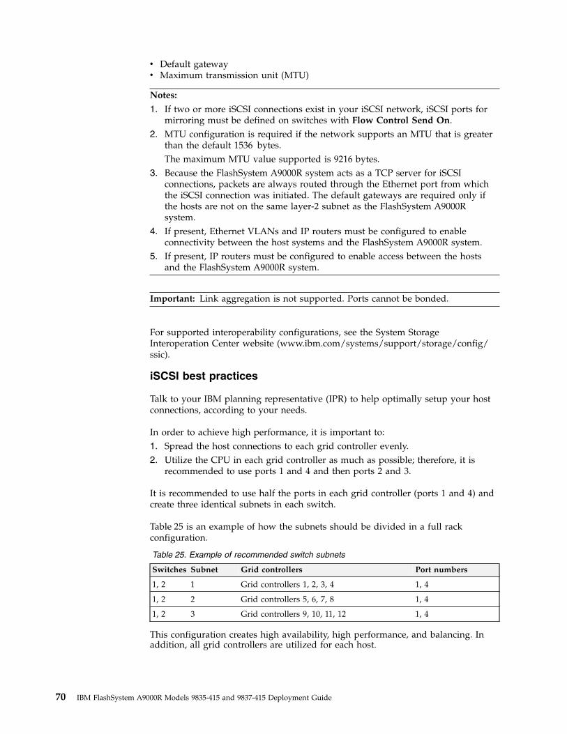
v Default gatewayv Maximum transmission unit (MTU)
Notes:
1. If two or more iSCSI connections exist in your iSCSI network, iSCSI ports formirroring must be defined on switches with Flow Control Send On.
2. MTU configuration is required if the network supports an MTU that is greaterthan the default 1536 bytes.The maximum MTU value supported is 9216 bytes.
3. Because the FlashSystem A9000R system acts as a TCP server for iSCSIconnections, packets are always routed through the Ethernet port from whichthe iSCSI connection was initiated. The default gateways are required only ifthe hosts are not on the same layer-2 subnet as the FlashSystem A9000Rsystem.
4. If present, Ethernet VLANs and IP routers must be configured to enableconnectivity between the host systems and the FlashSystem A9000R system.
5. If present, IP routers must be configured to enable access between the hostsand the FlashSystem A9000R system.
Important: Link aggregation is not supported. Ports cannot be bonded.
For supported interoperability configurations, see the System StorageInteroperation Center website (www.ibm.com/systems/support/storage/config/ssic).
iSCSI best practices
Talk to your IBM planning representative (IPR) to help optimally setup your hostconnections, according to your needs.
In order to achieve high performance, it is important to:1. Spread the host connections to each grid controller evenly.2. Utilize the CPU in each grid controller as much as possible; therefore, it is
recommended to use ports 1 and 4 and then ports 2 and 3.
It is recommended to use half the ports in each grid controller (ports 1 and 4) andcreate three identical subnets in each switch.
Table 25 is an example of how the subnets should be divided in a full rackconfiguration.
Table 25. Example of recommended switch subnets
Switches Subnet Grid controllers Port numbers
1, 2 1 Grid controllers 1, 2, 3, 4 1, 4
1, 2 2 Grid controllers 5, 6, 7, 8 1, 4
1, 2 3 Grid controllers 9, 10, 11, 12 1, 4
This configuration creates high availability, high performance, and balancing. Inaddition, all grid controllers are utilized for each host.
70 IBM FlashSystem A9000R Models 9835-415 and 9837-415 Deployment Guide
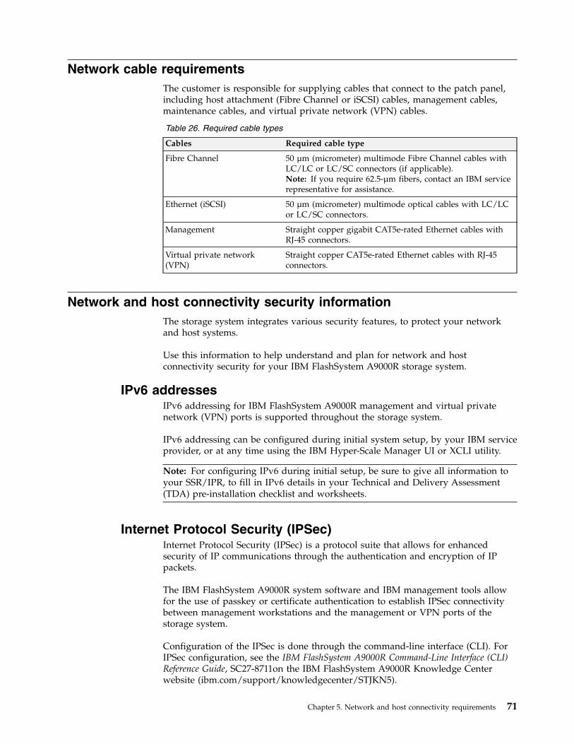
Network cable requirementsThe customer is responsible for supplying cables that connect to the patch panel,including host attachment (Fibre Channel or iSCSI) cables, management cables,maintenance cables, and virtual private network (VPN) cables.
Table 26. Required cable types
Cables Required cable type
Fibre Channel 50 µm (micrometer) multimode Fibre Channel cables withLC/LC or LC/SC connectors (if applicable).Note: If you require 62.5-µm fibers, contact an IBM servicerepresentative for assistance.
Ethernet (iSCSI) 50 µm (micrometer) multimode optical cables with LC/LCor LC/SC connectors.
Management Straight copper gigabit CAT5e-rated Ethernet cables withRJ-45 connectors.
Virtual private network(VPN)
Straight copper CAT5e-rated Ethernet cables with RJ-45connectors.
Network and host connectivity security informationThe storage system integrates various security features, to protect your networkand host systems.
Use this information to help understand and plan for network and hostconnectivity security for your IBM FlashSystem A9000R storage system.
IPv6 addressesIPv6 addressing for IBM FlashSystem A9000R management and virtual privatenetwork (VPN) ports is supported throughout the storage system.
IPv6 addressing can be configured during initial system setup, by your IBM serviceprovider, or at any time using the IBM Hyper-Scale Manager UI or XCLI utility.
Note: For configuring IPv6 during initial setup, be sure to give all information toyour SSR/IPR, to fill in IPv6 details in your Technical and Delivery Assessment(TDA) pre-installation checklist and worksheets.
Internet Protocol Security (IPSec)Internet Protocol Security (IPSec) is a protocol suite that allows for enhancedsecurity of IP communications through the authentication and encryption of IPpackets.
The IBM FlashSystem A9000R system software and IBM management tools allowfor the use of passkey or certificate authentication to establish IPSec connectivitybetween management workstations and the management or VPN ports of thestorage system.
Configuration of the IPSec is done through the command-line interface (CLI). ForIPSec configuration, see the IBM FlashSystem A9000R Command-Line Interface (CLI)Reference Guide, SC27-8711on the IBM FlashSystem A9000R Knowledge Centerwebsite (ibm.com/support/knowledgecenter/STJKN5).
Chapter 5. Network and host connectivity requirements 71
Authorization rules for managing multiple systemsUse this information to understand authorization rules for managing multiplesystems.
Because user credentials are stored locally on each storage system, you must keepthe same user name and password on each separate IBM FlashSystem A9000 andA9000R system to allow for quick transitions between systems in the IBMHyper-Scale Manager UI.
This approach is especially useful in remote mirroring configurations, where thestorage administrator is required to switch from source to target system. For moreinformation on mirroring, see IBM FlashSystem A9000R Product Overview, SC27-8559on the IBM FlashSystem A9000R Knowledge Center website (ibm.com/support/knowledgecenter/STJKN5).
To allow simultaneous access to multiple systems, the simplest approach is to havecorresponding passwords manually synchronized among those systems. Thestorage administrator can easily switch between these systems for the activitieswithout needing to log on each time with another password. Each storage systemwhere the user was successfully authenticated is listed in the System view of theUI.
For information about managing multiple systems in LDAP authentication mode,see “Lightweight Directory Access Protocol (LDAP).”
Lightweight Directory Access Protocol (LDAP)The IBM FlashSystem A9000R systems offer the capability to use LDAPserver-based user authentication.
For more detailed information about LDAP products, role mapping, defining onyour storage system, and more, see Security > LDAP with FlashSystem A9000 andFlashSystem A9000R in the IBM FlashSystem A9000 and IBM FlashSystem A9000R:Architecture, Implementation and Usage Redbook, SG24-8345.
When LDAP authentication is enabled, the storage system accesses a specifiedLDAP directory to authenticate users whose credentials are maintained in theLDAP directory (except for the admin, technician, maintenance, and developmentusers, which remain locally administered and maintained).
Important: As a preferred practice, the LDAP server and the FlashSystem A9000Rstorage system must have their clocks synchronized to the same time source, beregistered, and be configured to use the same DNS servers.
Product selection
LDAP authentication of the storage system supports three LDAP server products:v Microsoft Active Directoryv Oracle Directory Server Enterprise Editionv OpenLDAP
The current skill set of your IT staff is always an important consideration whenchoosing any products for centralized user authentication. If you have skills inrunning a particular directory server, it might be a wise choice to standardize on
72 IBM FlashSystem A9000R Models 9835-415 and 9837-415 Deployment Guide

this server because your skilled people will best be able to customize and tune theserver. your experts will be able to provide the most reliable and highly availableimplementation for the LDAP infrastructure.
Role mapping
Before any LDAP user can be granted access to the storage system, the user mustbe a member of an appropriate LDAP group.
Important: An LDAP user cannot be a member of more than one LDAP group, soit cannot be associated with more than one storage system role mapping.
When initially planning to use LDAP-based authentication with your storagesystem, the LDAP attribute can be used for role mapping. The type of LDAP objectclasses used to create a user account for system authentication depends on the typeof LDAP server being used.
The Oracle Directory server and Open LDAP use the inetOrgPerson LDAP objectclass, and Active Directory uses the organizationalperson LDAP object class fordefinition of user accounts for storage system authentication.
For a definition of the inetOrgPerson LDAP object class and list of attributes, seethe Internet FAQ archive website:
www.faqs.org/rfcs/rfc2798.html
For a definition of the organizationalperson LDAP object class and list ofattributes, see the Microsoft website:
msdn.microsoft.com/en-us/library/ms683883 (VS.85).aspx
The role mapping can be done by either assigning the appropriate attribute valuethrough the ldap_config_set CLI command, or through the IBM Hyper-ScaleManager UI.
Managing multiple systems in LDAP authentication mode andsingle sign-on (SSO)
The task of managing multiple IBM FlashSystem A9000 and A9000R systems canbe simplified by using LDAP authentication mode.
As a result of all user credentials being stored centrally in the LDAP directory, it isno longer necessary to synchronize user credentials among multiple storagesystems. After a user account is registered in LDAP, multiple storage systems canuse credentials stored in LDAP directory for authentication.
Because the user's password is stored in the LDAP directory, all connected storagesystems authenticate the user with the password. If the password is changed, allstorage systems automatically accept the new password.
This mode of operation is often referred to as single sign-on (SSO). SSO allows forquick transitions between systems in the IBM Hyper-Scale Manager UI because thepassword is only entered once.
This approach is especially useful in remote mirroring configurations, where thestorage administrator is required to frequently switch from source to target system.
Chapter 5. Network and host connectivity requirements 73
For more information on remote mirroring, see the IBM FlashSystem A9000RProduct Overview, SC27-8559 on the IBM FlashSystem A9000R Knowledge Centerwebsite (ibm.com/support/knowledgecenter/STJKN5).
Security LDAP with Secure Sockets Layer (SSL)
In any authentication scenario, information is exchanged between the LDAP serverand your storage system where access is being sought. SSL can be used toimplement secure communications between the LDAP client and server. LDAPover SSL (LDAPS), the secure version of the LDAP protocol, allows a setup whereuser passwords never appear on the wire in clear text.
SSL provides methods for establishing identity using X.509 certificates andensuring message privacy and integrity using encryption.
To create an SSL connection, the LDAP server must have a digital certificate signedby a trusted certificate authority (CA). Companies have the choice of using atrusted CA from another vendor or creating their own certificate authority.
To be operational, SSL must be configured on both the client (IBM FlashSystemA9000 or FlashSystem A9000R storage system) and the server (LDAP server).Server configuration includes generating a certificate request, obtaining a servercertificate from a CA, and installing the server and CA certificates.
When a new LDAP server is added to the storage system configuration, a securitycertificate can be entered in the optional certificate field. If the LDAP server wasoriginally added without a certificate, you must remove that definition first andadd a definition with the certificate.
Important: When defining the LDAP server with a security certificate in thestorage system, the fully qualified name of the LDAP server must match the"issued to name" in the client's certificate.
LDAP registration in the server can be done either through the UI or through theCLI, however, the UI has file upload capabilities and when using the CLI, you willneed to cut and paste a long string containing the certificate.
Maintaining SSL certificates:
v New SSL certificates must be installed before the existing ones expire.v If you let an SSL certificates expire, your storage system LDAP authentication is
no longer possible until you either disable SSL or install the new certificate onboth the LDAP server and the FlashSystem A9000 and/or FlashSystem A9000Rservers.
v Before an SSL certificate expires, the storage system issues three notificationevents. Events are generated 30, 14, and 7 days before expiration.
74 IBM FlashSystem A9000R Models 9835-415 and 9837-415 Deployment Guide
Chapter 6. Planning for physical shipment
Ensure that your environment meets the standard delivery clearance and weightrequirements for the IBM FlashSystem A9000R system.
Prepare for equipment delivery so that professional movers or riggers cantransport the equipment to the final installation site. If you cannot completepreparations at the time of delivery, you must make your own arrangements forthe professional movers to complete transportation later.
Important: Use only professional movers to transport the equipment.
The IBM service representative can minimally reposition the rack at the installationsite, as required.
The following information describes how to plan for the physical shipment of yourstorage system:v “Planning to receive delivery”v “Planning for relocation” on page 76v “Shipment weights and dimensions” on page 76
Planning to receive deliveryThe professional movers or riggers are responsible for delivering and unloadingthe IBM FlashSystem A9000R system as close to its final destination as possible.You must ensure that the loading ramp and receiving area can accommodate thestorage system shipment.
Procedure
Use the following steps to ensure that the receiving area and loading ramp cansafely accommodate the delivery of your storage system:1. Coordinate a technical survey with the IBM service representative to plan the
loading path from the truck to the server room.2. Determine the packaged weight and dimensions of the FlashSystem A9000R
system container and other containers that you to be received (see “Shipmentweights and dimensions” on page 76).
3. Ensure that the loading dock, receiving area, all doors, and elevators can safelysupport the packaged weight and dimensions of the shipping containers.If the rack height or weight must be reduced for delivery to locations wheredoorway heights are smaller than the delivery clearances, the height andweight reduced shipping features (feature codes AFR2 or AFR3) must beordered. For information about the weight and height reduction features, see“Height reduced shipping option” on page 17 and “Weight-reduced shippingoption” on page 17.
Important: The rack is more easily moved when on a pallet, and the rack castersmight damage floors and carpets; therefore, roll the rack into position on its owncasters only when necessary.
© Copyright IBM Corp. 2016, 2017 75
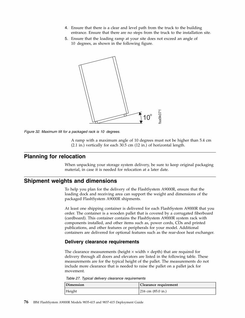
4. Ensure that there is a clear and level path from the truck to the buildingentrance. Ensure that there are no steps from the truck to the installation site.
5. Ensure that the loading ramp at your site does not exceed an angle of10 degrees, as shown in the following figure.
A ramp with a maximum angle of 10 degrees must not be higher than 5.4 cm(2.1 in.) vertically for each 30.5 cm (12 in.) of horizontal length.
Planning for relocationWhen unpacking your storage system delivery, be sure to keep original packagingmaterial, in case it is needed for relocation at a later date.
Shipment weights and dimensionsTo help you plan for the delivery of the FlashSystem A9000R, ensure that theloading dock and receiving area can support the weight and dimensions of thepackaged FlashSystem A9000R shipments.
At least one shipping container is delivered for each FlashSystem A9000R that youorder. The container is a wooden pallet that is covered by a corrugated fiberboard(cardboard). This container contains the FlashSystem A9000R system rack withcomponents installed, and other items such as, power cords, CDs and printedpublications, and other features or peripherals for your model. Additionalcontainers are delivered for optional features such as the rear-door heat exchanger.
Delivery clearance requirements
The clearance measurements (height × width × depth) that are required fordelivery through all doors and elevators are listed in the following table. Thesemeasurements are for the typical height of the pallet. The measurements do notinclude more clearance that is needed to raise the pallet on a pallet jack formovement.
Table 27. Typical delivery clearance requirements
Dimension Clearance requirement
Height 216 cm (85.0 in.)
10
fsa9k071
Figure 32. Maximum tilt for a packaged rack is 10 degrees.
76 IBM FlashSystem A9000R Models 9835-415 and 9837-415 Deployment Guide

Table 27. Typical delivery clearance requirements (continued)
Dimension Clearance requirement
Depth 144 cm (56.7 in.)
Width 94 cm (37.0 in.)
Delivery weight requirements
The path from the truck and to the server room must support the weight of therack, including packaging materials.
Table 28. Floor weight-support requirements
Grid element configuration Total weight
12 grid controllers and 6 flash enclosures 986 kg (2174 lbs)
10 grid controllers and 5 flash enclosures 906 kg (1998 lbs)
8 grid controllers and 4 flash enclosures 826 kg (1821 lbs)
6 grid controllers and 3 flash enclosures 746 kg (1645 lbs)
4 grid controllers and 2 flash enclosures 666 kg (1468 lbs)
Chapter 6. Planning for physical shipment 77

78 IBM FlashSystem A9000R Models 9835-415 and 9837-415 Deployment Guide
Chapter 7. Planning for remote support, on-site service, andmaintenance
This section provides you with information in order to prepare you for optimalsupport and software maintenance.
Remote support, on-site service, and maintenance planning considerations arelisted in the following sections:v “Planning for remote support connection”v “Planning for Call Home” on page 81v “Required support information” on page 84v “Support and software maintenance security information” on page 86
Planning for remote support connectionIBM Remote Support Center is a management system used by authorized IBMservice representatives to provide remote support and problem-determinationassistance over a secure network interface. The remote support connection is usedeither before or after parts are called out by the internal diagnostic tests of thestorage system. IBM authorized personnel use remote support connections toperform real-time problem analysis and isolation.
Remote support access is obtained over a dedicated network connection. Whenusing this method, the storage system is connected to the IBM Remote SupportCenter through one of the virtual private network (VPN) ports or managementports on the patch panel. For more connectivity information, see “Networkconnections for management” on page 63.
The IBM Remote Support Center has three components:v The IBM Remote Support Center is software that is installed on the storage
system and handles remote support connectivity.It relies on a single outgoing TCP connection and is not able to receive inboundconnections of any kind. The remote support client is controlled by using thecommand-line interface (CLI) commands and starts a connection, terminates aconnection (due to timeout or customer request), and attempts to reconnectwhen the connection is terminated unexpectedly.
v The front servers serve as a hub at which the storage system and theremote-support back server connect.The front servers are located in an IBM DMZ and receive and maintainconnections from the remote support client and the back server. The frontservers are strictly inbound and do not initiate any outbound communication.No sensitive information is stored on the front server, and all data passingthrough the front server from the client to the back server is encrypted, so thefront server or a malicious entity in control of a front server cannot access thisdata.
v One or more back servers are located within the IBM intranet. Only IBM servicerepresentatives that are authorized to perform remote support of the storagesystem can access these servers.The back server authenticates the IBM service representative, provides the IBMservice representative with a user interface through which to choose a system to
© Copyright IBM Corp. 2016, 2017 79
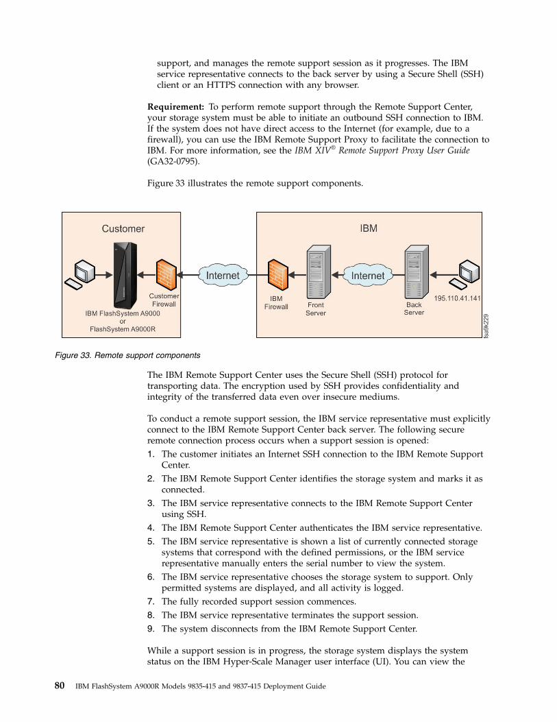
support, and manages the remote support session as it progresses. The IBMservice representative connects to the back server by using a Secure Shell (SSH)client or an HTTPS connection with any browser.
Requirement: To perform remote support through the Remote Support Center,your storage system must be able to initiate an outbound SSH connection to IBM.If the system does not have direct access to the Internet (for example, due to afirewall), you can use the IBM Remote Support Proxy to facilitate the connection toIBM. For more information, see the IBM XIV® Remote Support Proxy User Guide(GA32-0795).
Figure 33 illustrates the remote support components.
The IBM Remote Support Center uses the Secure Shell (SSH) protocol fortransporting data. The encryption used by SSH provides confidentiality andintegrity of the transferred data even over insecure mediums.
To conduct a remote support session, the IBM service representative must explicitlyconnect to the IBM Remote Support Center back server. The following secureremote connection process occurs when a support session is opened:1. The customer initiates an Internet SSH connection to the IBM Remote Support
Center.2. The IBM Remote Support Center identifies the storage system and marks it as
connected.3. The IBM service representative connects to the IBM Remote Support Center
using SSH.4. The IBM Remote Support Center authenticates the IBM service representative.5. The IBM service representative is shown a list of currently connected storage
systems that correspond with the defined permissions, or the IBM servicerepresentative manually enters the serial number to view the system.
6. The IBM service representative chooses the storage system to support. Onlypermitted systems are displayed, and all activity is logged.
7. The fully recorded support session commences.8. The IBM service representative terminates the support session.9. The system disconnects from the IBM Remote Support Center.
While a support session is in progress, the storage system displays the systemstatus on the IBM Hyper-Scale Manager user interface (UI). You can view the
Figure 33. Remote support components
80 IBM FlashSystem A9000R Models 9835-415 and 9837-415 Deployment Guide
process of phasing out a component or the restart of customer-visible systemservices as it happens. The customer has full control over whether to proceed witha support session by using mechanisms such as timeout or force-disconnect. If asession disconnects unexpectedly, the IBM service representative can resume thesession when the storage system next connects to the Remote Support Center.
Remote support for severe system conditionsA remote support connection may be established automatically, when activated, ifsevere system conditions (critical issues) are seen in the system and access to themachine is blocked to the host. Immediate action is necessary so that waiting forsession connection is not necessary. This function is also known as “XRSC onsevere system conditions”.
Important: Enabling the remote support for severe system conditions is stronglyrecommended in order to keep system repair time to a minimum and in order toresume connectivity to hosts as fast as possible. This allows an IBM servicerepresentative to access the system remotely and start the repair actionimmediately.
Remote support for severe system conditions permits a remote support accesswithout the need for the customer to initiate the SSH session towards the remotesupport center. It also eliminates the need to dispatch an IBM servicerepresentative to the customer site in order to initiate this session to do so.
The remote support for severe system conditions can be configured by the IBMservice representative at the time of the storage system installation. Thisinformation is communicated through the Technical and Delivery Assessment(TDA) checklist and worksheets.
Note: If remote support for severe system conditions is not enabled at the time ofinstallation, you can enable these actions at any time, using the XCLI utility. Usethe support_center_config command to configure the automatic connection to asupport center, setting automatically_connect to yes. For more detailedinformation, see IP configuration commands > Defining a support centerconnection on restart in the IBM FlashSystem A9000R Command-Line Interface (CLI)Reference Guide (SC27-8711).
Planning for Call HomeUsing Call Home, you can set up the IBM FlashSystem A9000R system toautomatically send pre-failure or failure notifications to the IBM TroubleshootingTicketing System in the IBM Service Center. You can also configure the storagesystem to automatically send alerts directly to you. Call Home cannot acceptincoming communication, which means that the IBM Service Center cannot contactthe FlashSystem A9000R system using Call Home.
When certain events occur in the FlashSystem A9000R system, Call Home sends anotification to the IBM Service Center. After receiving the notification, IBM servicepersonnel analyze the problem promptly and take appropriate action. If theproblem requires service, an IBM service representative is sent to your site withany necessary replacement parts. With access to the FlashSystem A9000R system,IBM service personnel can perform service tasks, such as viewing error logs andproblem logs or initiating trace and dump retrievals.
Chapter 7. Planning for remote support, on-site service, and maintenance 81
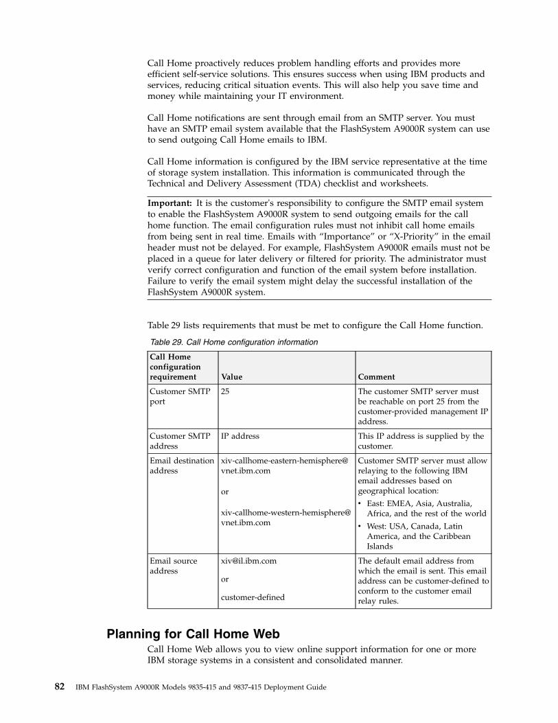
Call Home proactively reduces problem handling efforts and provides moreefficient self-service solutions. This ensures success when using IBM products andservices, reducing critical situation events. This will also help you save time andmoney while maintaining your IT environment.
Call Home notifications are sent through email from an SMTP server. You musthave an SMTP email system available that the FlashSystem A9000R system can useto send outgoing Call Home emails to IBM.
Call Home information is configured by the IBM service representative at the timeof storage system installation. This information is communicated through theTechnical and Delivery Assessment (TDA) checklist and worksheets.
Important: It is the customer's responsibility to configure the SMTP email systemto enable the FlashSystem A9000R system to send outgoing emails for the callhome function. The email configuration rules must not inhibit call home emailsfrom being sent in real time. Emails with “Importance” or “X-Priority” in the emailheader must not be delayed. For example, FlashSystem A9000R emails must not beplaced in a queue for later delivery or filtered for priority. The administrator mustverify correct configuration and function of the email system before installation.Failure to verify the email system might delay the successful installation of theFlashSystem A9000R system.
Table 29 lists requirements that must be met to configure the Call Home function.
Table 29. Call Home configuration information
Call Homeconfigurationrequirement Value Comment
Customer SMTPport
25 The customer SMTP server mustbe reachable on port 25 from thecustomer-provided management IPaddress.
Customer SMTPaddress
IP address This IP address is supplied by thecustomer.
Email destinationaddress
or
Customer SMTP server must allowrelaying to the following IBMemail addresses based ongeographical location:
v East: EMEA, Asia, Australia,Africa, and the rest of the world
v West: USA, Canada, LatinAmerica, and the CaribbeanIslands
Email sourceaddress
or
customer-defined
The default email address fromwhich the email is sent. This emailaddress can be customer-defined toconform to the customer emailrelay rules.
Planning for Call Home WebCall Home Web allows you to view online support information for one or moreIBM storage systems in a consistent and consolidated manner.
82 IBM FlashSystem A9000R Models 9835-415 and 9837-415 Deployment Guide
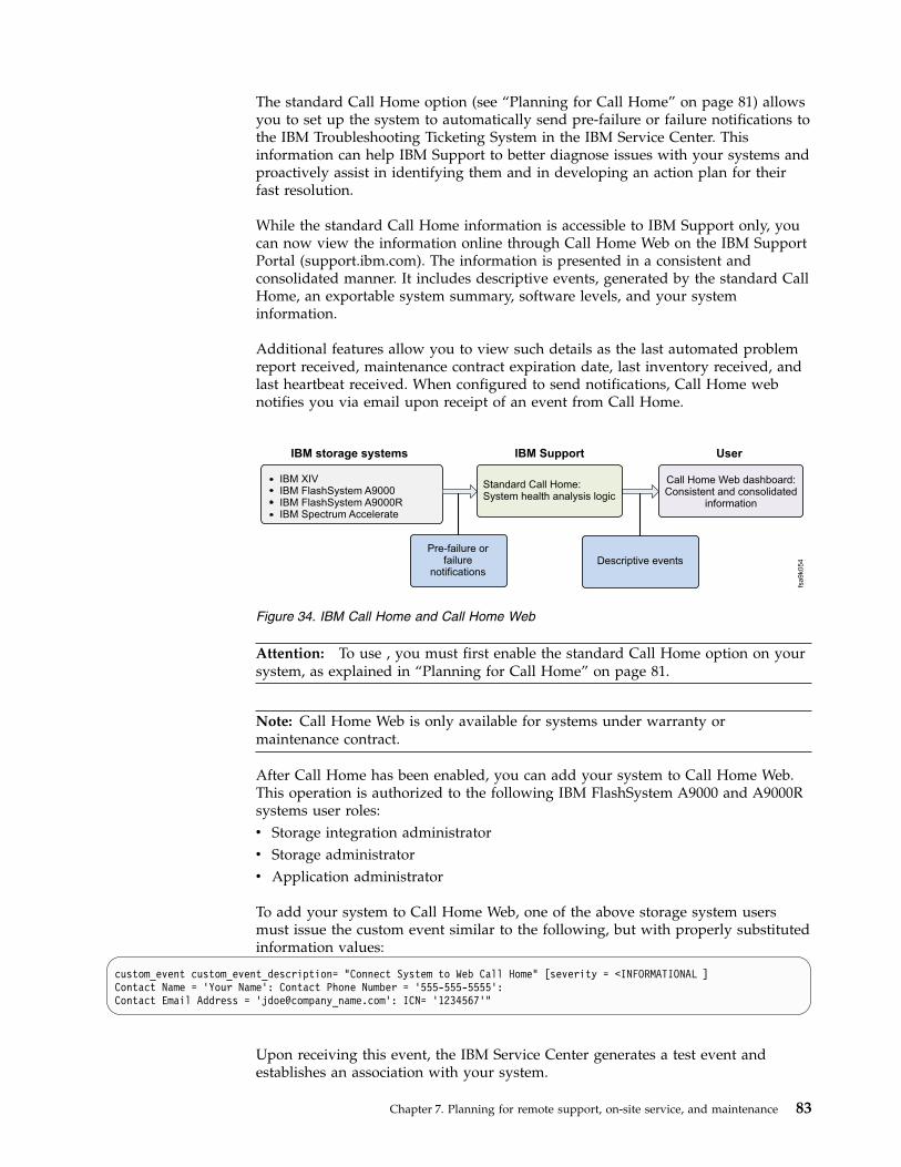
The standard Call Home option (see “Planning for Call Home” on page 81) allowsyou to set up the system to automatically send pre-failure or failure notifications tothe IBM Troubleshooting Ticketing System in the IBM Service Center. Thisinformation can help IBM Support to better diagnose issues with your systems andproactively assist in identifying them and in developing an action plan for theirfast resolution.
While the standard Call Home information is accessible to IBM Support only, youcan now view the information online through Call Home Web on the IBM SupportPortal (support.ibm.com). The information is presented in a consistent andconsolidated manner. It includes descriptive events, generated by the standard CallHome, an exportable system summary, software levels, and your systeminformation.
Additional features allow you to view such details as the last automated problemreport received, maintenance contract expiration date, last inventory received, andlast heartbeat received. When configured to send notifications, Call Home webnotifies you via email upon receipt of an event from Call Home.
Attention: To use , you must first enable the standard Call Home option on yoursystem, as explained in “Planning for Call Home” on page 81.
Note: Call Home Web is only available for systems under warranty ormaintenance contract.
After Call Home has been enabled, you can add your system to Call Home Web.This operation is authorized to the following IBM FlashSystem A9000 and A9000Rsystems user roles:v Storage integration administratorv Storage administratorv Application administrator
To add your system to Call Home Web, one of the above storage system usersmust issue the custom event similar to the following, but with properly substitutedinformation values:
custom_event custom_event_description= "Connect System to Web Call Home" [severity = <INFORMATIONAL ]Contact Name = ’Your Name’: Contact Phone Number = ’555-555-5555’:Contact Email Address = ’jdoe@company_name.com’: ICN= ’1234567’"
Upon receiving this event, the IBM Service Center generates a test event andestablishes an association with your system.
IBM storage systems
Pre-failure orfailure
notificationsDescriptive events
IBM XIVIBM FlashSystem A9000IBM FlashSystem A9000RIBM Spectrum Accelerate
IBM Support
Standard Call Home:System health analysis logic
User
Call Home Web dashboard:Consistent and consolidated
information
fsa9k054
Figure 34. IBM Call Home and Call Home Web
Chapter 7. Planning for remote support, on-site service, and maintenance 83
To disconnect a storage system from Call Home Web:v From the System Details page and click Remove System from Call Home Web.
Note: You can only remove a system that is fully added (activated and confirmed).If you need to remove a system that was accidentally added or cannot beconfirmed, click Feedback and request that the system be removed.
For comprehensive information about Call Home Web, see IBM Call Homeassistance webpage (ibm.biz/call-home-guide).
Required support informationUse this information to help prepare for support requests.
Have the following information on hand when calling for a support request for astorage system:v Phone number of machine locationv Machine serial number
Figure 35 on page 85 depicts the location of the serial number on the front of aFlashSystem A9000R rack.
Figure 36 on page 86 depicts the location of the serial number on the rear of aFlashSystem A9000R rack.
84 IBM FlashSystem A9000R Models 9835-415 and 9837-415 Deployment Guide
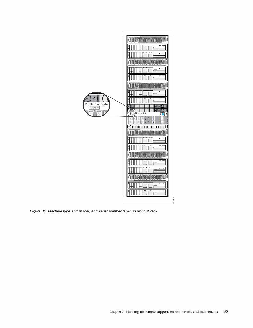
Figure 35. Machine type and model, and serial number label on front of rack
Chapter 7. Planning for remote support, on-site service, and maintenance 85
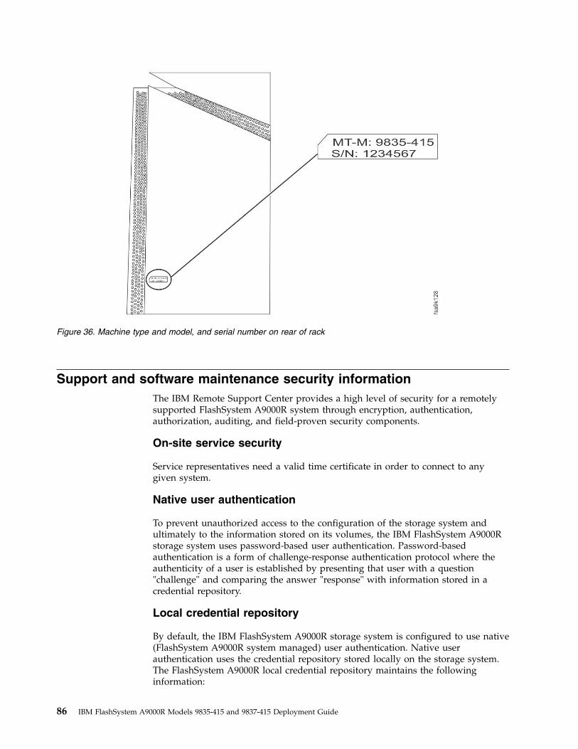
Support and software maintenance security informationThe IBM Remote Support Center provides a high level of security for a remotelysupported FlashSystem A9000R system through encryption, authentication,authorization, auditing, and field-proven security components.
On-site service security
Service representatives need a valid time certificate in order to connect to anygiven system.
Native user authentication
To prevent unauthorized access to the configuration of the storage system andultimately to the information stored on its volumes, the IBM FlashSystem A9000Rstorage system uses password-based user authentication. Password-basedauthentication is a form of challenge-response authentication protocol where theauthenticity of a user is established by presenting that user with a question"challenge" and comparing the answer "response" with information stored in acredential repository.
Local credential repository
By default, the IBM FlashSystem A9000R storage system is configured to use native(FlashSystem A9000R system managed) user authentication. Native userauthentication uses the credential repository stored locally on the storage system.The FlashSystem A9000R local credential repository maintains the followinginformation:
Figure 36. Machine type and model, and serial number on rear of rack
86 IBM FlashSystem A9000R Models 9835-415 and 9837-415 Deployment Guide

v User namev User passwordv User rolev User groupv Optional account attributes (such as email and phone numbers)
For more information about these role definitions and how to use them, seeSecurity > Native user authentication > Local credential repository in IBMFlashSystem A9000 and IBM FlashSystem A9000R: Architecture, Implementationand Usage on the IBM Storage Redbooks website (www.redbooks.ibm.com/portals/storage).
Chapter 7. Planning for remote support, on-site service, and maintenance 87

88 IBM FlashSystem A9000R Models 9835-415 and 9837-415 Deployment Guide
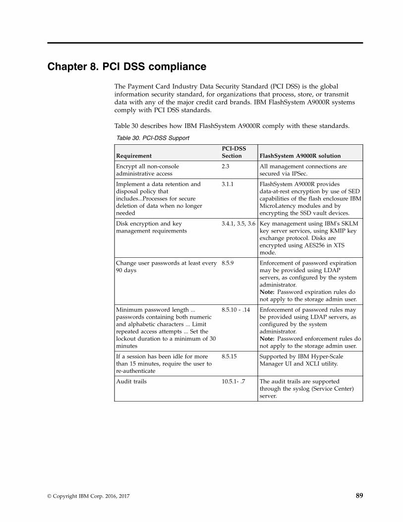
Chapter 8. PCI DSS compliance
The Payment Card Industry Data Security Standard (PCI DSS) is the globalinformation security standard, for organizations that process, store, or transmitdata with any of the major credit card brands. IBM FlashSystem A9000R systemscomply with PCI DSS standards.
Table 30 describes how IBM FlashSystem A9000R comply with these standards.
Table 30. PCI-DSS Support
RequirementPCI-DSSSection FlashSystem A9000R solution
Encrypt all non-consoleadministrative access
2.3 All management connections aresecured via IPSec.
Implement a data retention anddisposal policy thatincludes...Processes for securedeletion of data when no longerneeded
3.1.1 FlashSystem A9000R providesdata-at-rest encryption by use of SEDcapabilities of the flash enclosure IBMMicroLatency modules and byencrypting the SSD vault devices.
Disk encryption and keymanagement requirements
3.4.1, 3.5, 3.6 Key management using IBM's SKLMkey server services, using KMIP keyexchange protocol. Disks areencrypted using AES256 in XTSmode.
Change user passwords at least every90 days
8.5.9 Enforcement of password expirationmay be provided using LDAPservers, as configured by the systemadministrator.Note: Password expiration rules donot apply to the storage admin user.
Minimum password length ...passwords containing both numericand alphabetic characters ... Limitrepeated access attempts ... Set thelockout duration to a minimum of 30minutes
8.5.10 - .14 Enforcement of password rules maybe provided using LDAP servers, asconfigured by the systemadministrator.Note: Password enforcement rules donot apply to the storage admin user.
If a session has been idle for morethan 15 minutes, require the user tore-authenticate
8.5.15 Supported by IBM Hyper-ScaleManager UI and XCLI utility.
Audit trails 10.5.1- .7 The audit trails are supportedthrough the syslog (Service Center)server.
© Copyright IBM Corp. 2016, 2017 89

90 IBM FlashSystem A9000R Models 9835-415 and 9837-415 Deployment Guide

Notices
The legal notices pertain to IBM FlashSystem A9000R documentation.
This information was developed for products and services offered in the US. Thismaterial may be available from IBM in other languages. However, you may berequired to own a copy of the product or product version in that language in orderto access it.
IBM may not offer the products, services, or features discussed in this document inother countries. Consult your local IBM representative for information on theproducts and services currently available in your area. Any reference to an IBMproduct, program, or service is not intended to state or imply that only that IBMproduct, program, or service may be used. Any functionally equivalent product,program, or service that does not infringe any IBM intellectual property right maybe used instead. However, it is the user's responsibility to evaluate and verify theoperation of any non-IBM product, program, or service.
IBM may have patents or pending patent applications covering subject matterdescribed in this document. The furnishing of this document does not grant youany license to these patents. You can send license inquiries, in writing, to:
IBM Director of LicensingIBM CorporationNorth Castle Drive, MD-NC119Armonk, NY 10504-1785USA
INTERNATIONAL BUSINESS MACHINES CORPORATION PROVIDES THISPUBLICATION "AS IS" WITHOUT WARRANTY OF ANY KIND, EITHEREXPRESS OR IMPLIED, INCLUDING, BUT NOT LIMITED TO, THE IMPLIEDWARRANTIES OF NON-INFRINGEMENT, MERCHANTABILITY OR FITNESSFOR A PARTICULAR PURPOSE. Some states do not allow disclaimer of express orimplied warranties in certain transactions, therefore, this statement may not applyto you.
This information could include technical inaccuracies or typographical errors.Changes are periodically made to the information herein; these changes will beincorporated in new editions of the publication. IBM may make improvementsand/or changes in the product(s) and/or the program(s) described in thispublication at any time without notice.
Any references in this information to non-IBM Web sites are provided forconvenience only and do not in any manner serve as an endorsement of those Websites. The materials at those Web sites are not part of the materials for this IBMproduct and use of those Web sites is at your own risk.
IBM may use or distribute any of the information you supply in any way itbelieves appropriate without incurring any obligation to you.
The performance data and client examples cited are presented for illustrativepurposes only. Actual performance results may vary depending on specificconfigurations and operating conditions.
© Copyright IBM Corp. 2016, 2017 91

Information concerning non-IBM products was obtained from the suppliers ofthose products, their published announcements or other publicly available sources.IBM has not tested those products and cannot confirm the accuracy ofperformance, compatibility or any other claims related to non-IBM products.Questions on the capabilities of non-IBM products should be addressed to thesuppliers of those products.
TrademarksIBM, the IBM logo, and ibm.com are trademarks or registered trademarks ofInternational Business Machines Corp., registered in many jurisdictions worldwide.Other product and service names might be trademarks of IBM or other companies.A current list of IBM trademarks is available on the web at Copyright andtrademark information at www.ibm.com/legal/copytrade.shtml.
Adobe, the Adobe logo, PostScript, and the PostScript logo are either registeredtrademarks or trademarks of Adobe Systems Incorporated in the United States,and/or other countries.
Intel and Intel Xeon are trademarks or registered trademarks of Intel Corporationor its subsidiaries in the United States and other countries.
Microsoft and Windows are trademarks of Microsoft Corporation in the UnitedStates, other countries, or both.
Java and all Java-based trademarks and logos are trademarks or registeredtrademarks of Oracle and/or its affiliates.
Homologation statementThis product may not be certified in your country for connection by any meanswhatsoever to interfaces of public telecommunications networks. Furthercertification may be required by law prior to making any such connection. Contactan IBM representative or reseller for any questions.
Electronic emission noticesThis section contains the electronic emission notices or statements for the UnitedStates and other countries.
Federal Communications Commission StatementThis explains the Federal Communications Commission's (FCC’s) statement.
This equipment has been tested and found to comply with the limits for a Class Adigital device, pursuant to Part 15 of the FCC Rules. These limits are designed toprovide reasonable protection against harmful interference when the equipment isoperated in a commercial environment. This equipment generates, uses, and canradiate radio frequency energy and, if not installed and used in accordance withthe instruction manual, might cause harmful interference to radio communications.Operation of this equipment in a residential area is likely to cause harmfulinterference, in which case the user will be required to correct the interference athis own expense.
Properly shielded and grounded cables and connectors must be used in order tomeet FCC emission limits. IBM is not responsible for any radio or television
92 IBM FlashSystem A9000R Models 9835-415 and 9837-415 Deployment Guide

interference caused by using other than recommended cables and connectors, or byunauthorized changes or modifications to this equipment. Unauthorized changesor modifications could void the user's authority to operate the equipment.
This device complies with Part 15 of the FCC Rules. Operation is subject to thefollowing two conditions: (1) this device might not cause harmful interference, and(2) this device must accept any interference received, including interference thatmight cause undesired operation.
Industry Canada Compliance StatementThis Class A digital apparatus complies with Canadian ICES-003.
Cet appareil numérique de la classe A est conform à la norme NMB-003 duCanada.
Australia and New Zealand Class A Statement
Attention: This is a Class A product. In a domestic environment this productmight cause radio interference in which case the user might be required to takeadequate measures.
European Union Electromagnetic Compatibility DirectiveThis product is in conformity with the protection requirements of European Union(EU) Council Directive 2014/30/EC on the approximation of the laws of theMember States relating to electromagnetic compatibility. IBM cannot acceptresponsibility for any failure to satisfy the protection requirements resulting from anon-recommended modification of the product, including the fitting of non-IBMoption cards.
Attention: This is an EN 55032 Class A product. In a domestic environment thisproduct might cause radio interference in which case the user might be required totake adequate measures.
Responsible Manufacturer:
International Business Machines Corp.New Orchard RoadArmonk, New York 10504914-499-1900
European community contact:
IBM Deutschland GmbHTechnical Relations EuropeIBM-Allee 1D-71139 Ehningen, Germany
Germany Electromagnetic Compatibility DirectiveDeutschsprachiger EU Hinweis: Hinweis für Geräte der Klasse A EU-Richtliniezur Elektromagnetischen Verträglichkeit
Notices 93

Dieses Produkt entspricht den Schutzanforderungen der EU-Richtlinie2004/108/EG zur Angleichung der Rechtsvorschriften über die elektromagnetischeVerträglichkeit in den EU-Mitgliedsstaaten und hält die Grenzwerte der EN 55032Klasse A ein.
Um dieses sicherzustellen, sind die Geräte wie in den Handbüchern beschrieben zuinstallieren und zu betreiben. Des Weiteren dürfen auch nur von der IBMempfohlene Kabel angeschlossen werden. IBM übernimmt keine Verantwortung fürdie Einhaltung der Schutzanforderungen, wenn das Produkt ohne Zustimmung derIBM verändert bzw. wenn Erweiterungskomponenten von Fremdherstellern ohneEmpfehlung der IBM gesteckt/eingebaut werden.
EN 55032 Klasse A Geräte müssen mit folgendem Warnhinweis versehen werden:
“Warnung: Dieses ist eine Einrichtung der Klasse A. Diese Einrichtung kann imWohnbereich Funk-Störungen verursachen; in diesem Fall kann vom Betreiberverlangt werden, angemessene Mabnahmen zu ergreifen und dafüraufzukommen.”
Deutschland: Einhaltung des Gesetzes über die elektromagnetischeVerträglichkeit von Geräten
Dieses Produkt entspricht dem “Gesetz über die elektromagnetische Verträglichkeitvon Geräten (EMVG).” Dies ist die Umsetzung der EU-Richtlinie 2004/108/EG inder Bundesrepublik Deutschland.
Zulassungsbescheinigung laut dem Deutschen Gesetz über dieelektromagnetische Verträglichkeit von Geräten (EMVG) (bzw. der EMC EGRichtlinie 2004/108/EG) für Geräte der Klasse A
Dieses Gerät ist berechtigt, in übereinstimmung mit dem Deutschen EMVG dasEG-Konformitätszeichen - CE - zu führen.
Verantwortlich für die Einhaltung der EMV Vorschriften ist der Hersteller:
International Business Machines Corp.New Orchard RoadArmonk,New York 10504Tel: 914-499-1900
Der verantwortliche Ansprechpartner des Herstellers in der EU ist:
IBM Deutschland GmbHTechnical Regulations, Abteilung M372IBM-Allee 1, 71139 Ehningen, GermanyTele: +49 (0) 800 225 5423 or +49 (0) 180 331 3233Email: [email protected]
: Das Gerät erfüllt die Schutzanforderungen nach EN 55024 und EN 55032Klasse A.
94 IBM FlashSystem A9000R Models 9835-415 and 9837-415 Deployment Guide
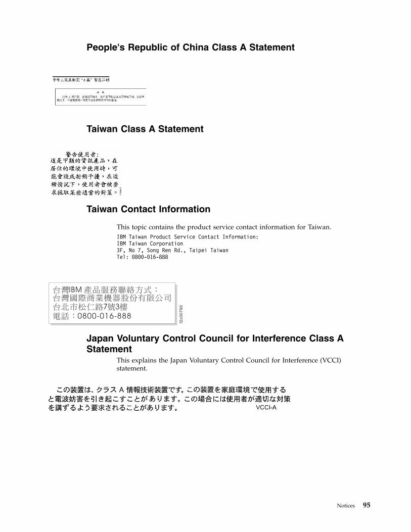
People's Republic of China Class A Statement
Taiwan Class A Statement
Taiwan Contact Information
This topic contains the product service contact information for Taiwan.IBM Taiwan Product Service Contact Information:IBM Taiwan Corporation3F, No 7, Song Ren Rd., Taipei TaiwanTel: 0800-016-888
Japan Voluntary Control Council for Interference Class AStatement
This explains the Japan Voluntary Control Council for Interference (VCCI)statement.
f2c0
07
90
Notices 95

Japan Electronics and Information Technology IndustriesAssociation Statement
This statement explains the Japan JIS C 61000-3-2 product wattage compliance.
This statement explains the Japan Electronics and Information TechnologyIndustries Association (JEITA) statement for products less than or equal to 20 A perphase.
This statement explains the JEITA statement for products greater than 20 A, singlephase.
This statement explains the JEITA statement for products greater than 20 A perphase, three-phase.
Korean Communications Commission Class A StatementThis explains the Korean Communications Commission (KCC) statement.
96 IBM FlashSystem A9000R Models 9835-415 and 9837-415 Deployment Guide

Russia Electromagnetic Interference Class A StatementThis statement explains the Russia Electromagnetic Interference (EMI) statement.
Notices 97

98 IBM FlashSystem A9000R Models 9835-415 and 9837-415 Deployment Guide

Index
Aacoustics
environmental requirements 37air circulation
environmental requirements 33air circulation and cooling
environmental requirements 33air filtration 35architecture
management port requirements 64network connections 63rack configurations 11
authorization rulesLDAP
security 72managing multiple systems 71multiple systems
security 72
Ccable requirements 71Call Home
configuration 81, 83web
See Call Home WebCall Home Web 83clearance requirements 76components and interconnection
options 10configuration options
Fibre channel 14flash enclosure 14grid controller 14height reduced shipping 17iSCSI 14MicroLatency modules 14rear-door heat exchanger 15RFID 18weight-weight reduced shipping 17
configuringiSCSI network 69network 66
considerationscontamination 35floor 20, 21heavy equipment xvmain power cables 29safety xvsite preparation xvsite safety xvweight-support 21
coolingenvironmental requirements 33
Ddelivery
clearance requirements 76shipment planning 75
delivery (continued)weight requirements 76
deployment overview 1
Eenvironment 33environmental
site requirements 32environmental acclimation 33environmental conditions 35environmental contamination 35environmental notices xi, xvienvironmental requirements
site requirements 35temperature thresholds and
events 35Ethernet
ports 69
FFC
See also Fibre channelSee Fibre Channel
feature codeAFR1 38
feature codes1050 291051 291052 291053 295001 145002 14AFE2 14AFE3 14AFR1 15, 26AFR2 17AFR3 17AFR5 18
Fibre channeloptions 14
Fibre Channelnetwork configuration 67
fire suppression xiiiflash enclosure
options 14floor and space requirements
floor-load 21non-raised floor 20, 25preparation 24, 25, 26rack dimensions 22, 23raised floor 20, 24rear-door heat exchanger 26service clearance 22, 23
floor-loadsite requirements 21
frequenciesSee power
Ggaseous contamination
considerations 35grid controller
Fibre Channel 14iSCSI 14options 14
Hheat exchanger
water specification 42heavy equipment xvheight reduced
shipping 17homologation 92host connectivity 63, 66, 67
IIBM Trouble Ticketing System 81, 83IEC 60950-1 xiInternet Protocol Security
security 71IPSec 71IPSEC
See Internet Protocol SecurityIPv6 71IPv6 addresses
security 71iSCSI
network configuration 69options 14
Llabels, safety information xilaser safety xiiLDAP 71
role mapping 72SSL 72SSO 72
lifting heavy equipment xvLightweight Directory Access
Protocol 72location, preparing xv
Mmain power cables
considerations 29feature codes for 29specifications 29
managing multiple systemsauthorization rules 71
multiple systemssecurity
LDAP 72SSO 72
© Copyright IBM Corp. 2016, 2017 99

Nnetwork and host connectivity
security 71, 72network and host connectivity
requirements 63Fibre Channel logical network 67Network configurations 66
network configurations 66Fibre Channel logical network 67
noiseenvironmental requirements 37
non-raised floorcabling 25considerations 20installation 25preparation 25requirements, heat exchanger 55site requirements 20
noticesenvironmental xi, xvilegal 91safety xi
notifications, through call home 81, 83
Ooperating environment
requirements 32operation vibrations
environmental requirements 37overview, deployment 1
Pparticulate contamination
considerations 35physical configuration
components and interconnectionoptions 10
physical shipmentdelivery 75planning 75relocation
planning 76planning
physical shipment 75delivery 75relocation 76
support 84planning overview 1power
consumption 27input voltage and frequencies 28input voltages and frequencies 28power consumption 27power sources 27site requirements 26, 27, 28source configurations 27
power consumptionsite requirements 27
power sourcesconfigurations 27site requirements 27
preparingnon-raised floor 25raised-floor 24
preparing (continued)rear-door heat exchanger 26
preparing the site xv
Rrack dimensions
site requirements 22, 23radio frequency identification device
See RFIDraised floor
cabling 24considerations 20hose requirements, heat
exchanger 51installation 24preparation 24site requirements 20
rear door heat exchangernon-raised floor requirements 55raised floor hose requirements 51
rear-door heat exchanger 15AFR1 38maintenance 60preparation 26site requirements 38water delivery specifications 44water specification 42
Rear-door heat exchangeroperating specifications 38performance 39preparing the site 41secondary cooling loop
parts and services 57relocation
planning 76remote support connection 79, 81remote support on restart 79, 81requirements
cables 71delivery clearance 76delivery weight 76environmental 32
acoustic declaration 37air circulation and cooling 33operation vibrations 37
network and host connectivity 63network configurations 66
Fibre Channel 67non-raised floor, heat exchanger 55operating environment 32power 26raised floor hose, heat exchanger 51rear-door heat exchanger 38Rear-door heat exchanger 38, 39, 41,
57RFID 18role mapping
securityLDAP 72
Ssafety
environmental notices xiinformation labels xi
safety (continued)laser xiinotices xi
secondary cooling loopSee Rear-door heat exchanger
securityLDAP
role mapping 72SSL 72with multiple systems 72
network and host 72authorization rules 72Internet Protocol Security 71IPv6 addresses 71multiple systems 72
Securityauthorization rules 71IPSec 71IPv6 71LDAP 71
service clearancesite requirements 22, 23
shipmentdelivery 75planning 75relocation
planning 76shipping options
height reduced 17weight-weight reduced 17
site requirementsfloor considerations 20floor-load 21non-raised floor 20, 25physical installation 20, 21, 22, 23,
24, 25power 27, 28, 29rack dimensions 22, 23raised floor 20raised-floor 24service clearance 22, 23weight-support 21
site requirementsrear-door heat exchangerphysical installation 26
site, preparing xvsound
environmental requirements 37SSL
LDAP 72support call
planning 84system environmental acclimation 33
Ttemperature thresholds and events 35trademarks 92
Vvibration
operationenvironmental requirements 37
voltageSee power
100 IBM FlashSystem A9000R Models 9835-415 and 9837-415 Deployment Guide

Wwater delivery specifications
heat exchanger 44water specification, heat exchanger 42weight requirements
delivery 76weight-reduced
shipping 17weight-support
See floor-load
XXRSC
See remote support on restart
Index 101

102 IBM FlashSystem A9000R Models 9835-415 and 9837-415 Deployment Guide


IBM®
Printed in USA
GC27-8565-03


![WAC 415 - 02 CHAPTER - Washingtonleg.wa.gov/CodeReviser/WACArchive/Documents/2015/WAC 415 - 02... · (2/27/14) [Ch. 415-02 WAC p. 1] Chapter 415-02 Chapter 415-02 WAC GENERAL PROVISIONS](https://img.dokumen.tips/doc/110x75/5ad016617f8b9aca598d40d7/wac-415-02-chapter-415-0222714-ch-415-02-wac-p-1-chapter-415-02.jpg)