Embed Size (px)
Citation preview
I UNDERCOUNTER DISHWASHER
IMPORTANT INSTALLER: LEAVE THESE INSTRUCTIONS WITH THE HOMEOWNER. HOMEOWNER: RETAIN THESE INSTRUCTIONS FOR FUTURE REFERENCE.
Ovens, Compactors, Room Air Conditioners, Dehumidifiers, Automatic Washers, Clothes Dryers+ Freezers, Refrigerator-Freezers, Ice Makers,DishwN
-,
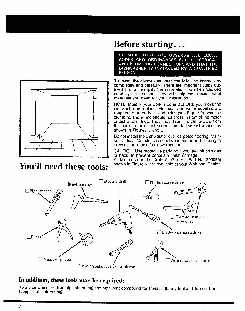
Before starting. . l
You’ll need these tools:
To install the dishwasher, read the following instructions completely and carefully. There are important steps out- lined that will simplify the installation job when followed carefully. In addition, they will help you decide what materials you need for your installation.
NOTE: Most of your work is done BEFORE you move the dishwasher into place. Electrical and water supplies are roughed in at the back and sides (see Figure 2) because plumbing and wiring should not cross in front of the motor or dishwasher legs. They should run straight forward from the back to their final connections to the dishwasher as shown in Figures 8 and 9.
Do not install the dishwasher over carpeted flooring. Main- tain at least VI” clearance between motor and flooring to prevent the motor from overheating.
CAUTION: Use protective padding if you lay unit on sides or back, to prevent porcelain finish damage. All kits, such as the Drain Air-Gap Kit (Part No. 300096) shown in Figure 6, are available at your Whirlpool Dealer.
nv-.L-l- __._ q Electric drill aPhillips screwdriver -
q Two’adjusiable wrenches
OPliers’ \ I,@ 2
q Measuring tape
i<w screwdriver
q Wire stripper or knife
q 1/4” Socket set & nut driver
In addition, these tools may be required: Two pipe wrenches (iron pipe plumbing) and pipe joint compound for threads; flaring tool and tube cutter (copper tube plumbing).
2
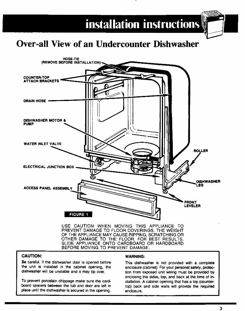
Over-all View of an Undercounter Dishwasher HOSE-TIE
(REMOVE BEFORE INSTALLAT
COUNTER-TOP ATTACH BRACKETS
DRAIN HOSE
DISHWASHER MOTOR & PUMP
\
WATER INLET VALVE
ACCESS PANEL ASSEMBLY
FRONT LEVELER
USE CAUTION WHEN MOVING THIS APPLIANCE TO PREVENT DAMAGE TO FLOOR COVERINGS. THE WEIGHT OF THE APPLIANCE MAY CAUSE RIPPING, SCRATCHING OR OTHER DAMAGE TO THE FLOOR. FOR BEST RESULTS, SLIDE APPLIANCE ONTO CARDBOARD OR HARDBOARD BEFORE MOVING TO PREVENT DAMAGE.
CAUTION: Be careful. If the dishwasher door is opened before the unit is installed in the cabinet opening, the dishwasher will be unstable and it may tip over.
To prevent porcelain chippage make sure the card-
WARNING:
This dishwasher is not provided with a complete enclosure (cabinet). For your personal safety, proteo tion from exposed unit wiring must be provided by enclosing the sides, top, and back at the time of in- stallation. A cabinet opening that has a top (counter-
board spacers between the tub and door are left in top) back and side walls will provide the required place until the dishwasher is secured in the opening. enclosure.
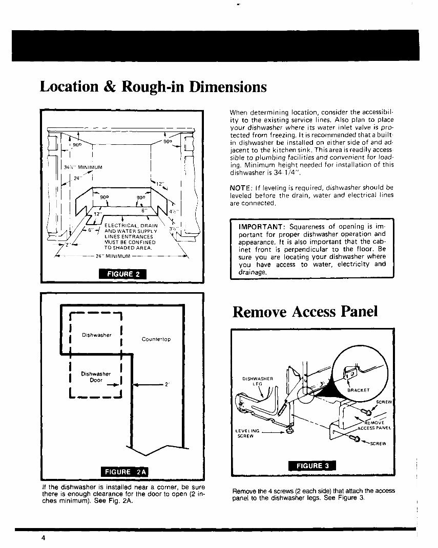
34%” MINIMUM
ELECTRICAL. DFiAIN
.
--
I- 7
l
I
DIshwasher I
I Countertop
I 1 I I
I Dishwasher I
I Door +I *- 2”
L --B A
If the dishwasher is installed near a corner, be sure there is enough clearance for the door to open (2 in- ches minimum). See Fig. 2A.
When determining location, consider the accessibil- ity to the existing service lines. Also plan to place your dishwasher where its water inlet valve is pro- tected from freezing. It is recommended that a built- in dishwasher be installed on either side of and ad- jacent to the kitchen sink. This area is readily access- sible to plumbing facilities and convenient for load- ing. Minimum height needed for installation of this dishwasher is 34-l /4”.
NOTE: If leveling is required, dishwasher should be leveled before the drain, water and electrical lines are connected.
IMPORTANT: Squareness of opening is im- portant for proper dishwasher operation and appearance. It is also important that the cab- inet front is perpendicular to the floor. Be sure you are locating your dishwasher where you have access to water, electricity and drainage.
Remove Access Panel
SCREW
Remove the 4 screws (2 each side) that attach the access panel to the dishwasher legs. See Figure 3.
4 ) I
Locating Your Drain, Water and Electrical Supply
I IMPORTANT: OBSERVE ALL LOCAL CODES AND ORDINANCES
Review this page in detail. Look at the location where the dishwasher is to be located. Double check(ti I/) that you have the correct water, electrical and drain supplies before attempting to make these connections.
NOTE: Figure 4 gives dimensional details that will be helpful when making the decisions on how to run the drain, water and electrical hook-ups.
Drain Review Figures 6 & 7 to determine where you will con- nect the dishwasher into your drain system. Cut the drain hose hole (11/z" or larger) in area shaded in Figure 2. Check BOTH sides of area to be cut BEFORE cutting, to prevent interference. If the cabinet sidewall is wood, sand the edges of the hole smooth. If the sidewall is metal, install a protective grommet Part No. 302797, available from your local Whirlpool dealer to cover the edge of the hole.
It is recommended that the drain line be connected to your house plumbing using a drain air-gap (Part No. 300096) available through your Whirlpool dealer.
NOTE: Some other brands of drain air-gaps restrict water flow excessively and can result in incomplete drain.
If local plumbing codes permit, your dishwasher may be connected directly to disposer or waste tee, provided that connection is made ahead of trap and is at least 20” above floor level. If additional drain line is required it must be a minimum of l/2)’ I.D. and should not be longer than 20 feet.
NOTE: To minimize vibration noise, the drain line must be routed so that it does not touch adjacent cabinet surfaces.
NOTE: When connecting to a separate drain trap, it must be vented.
Water Determine where you will connect the dishwasher into your hot water supply. Review Figure 8 and note the loca- tion of the water lines. The dishwasher water inlet valve has 3/” IPS (Iron Pipe Size) [l/2” copper tubing] female fitting. How much pipe or tubing will you need? Copper tubing must have a minimum O.D. of 3/e”. Pipe, a minimum of 3/e” IPS.
It is recommended that a shut-off valve be installed out- side of the dishwasher area.
Cut the access hole (approximately l/2” or larger) inside the shaded area as shown in Figure 2. Complete the plumbing rough-in before putting the dishwasher in place.
The maximum water pressure allowed is 120 PSI (Pounds Per Square Inch), dynamic. Minimum pressure is 15 PSI.
The temperature of the water should be at least 14OOF. Check this at your kitchen faucet. Let the water run before checking the temperature with a candy or meat thermometer.
Electrical Power Supply Determine where you will connect to the electrical sup ply. Review Figure 4 and 9, note the location of the elec- tric lines. Cut the access hole inside shaded area as shown in Figure 2.
A 120 Volt, 60 Hz, AC only, 15 Ampere (20 Ampere Max- imum) fused electrical supply is required (Time delay fuse or circuit breaker is recommended.) It is recommended that a separate circuit serving only this appliance be pro- vided. DO NOT use an extension cord.
Flexible Cord Connection Local codes may permit the use of a UL listed flexible three conductor cord terminated with a three prong grounding type plug.
It is recommended that cord kit 675456, available at your Whirlpool dealer or parts supplier, be used. If the cord kit is not available locally, the flexible cord used must be a three conductor 16 gauge cord that meets the National Electrical Code and local codes and ordinances for this type of installation. The length of the cord must not ex- ceed six feet. It must be routed so that it does not touch the dishwasher motor and/or the lower portion of the dishwasher tub. If the flexible cord is used, it must be plugged into a mating three prong grounding type wall receptacle, grounded in accordance with the National Electrical Code and local codes and ordinances.
Follow the instructions packaged with the flexible cord and make sure the following requirements are met.
1. A UL approved strain relief must be installed at the dishwasher junction box.
2. The power supply receptacle is installed as follows:
5
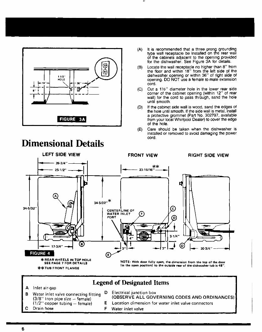
Dimensional Details LEFT SIDE VIEW
- 26-314” -
- 251/2” - II
I 34.5132”
I
*REAR WHEELS IN TOP HOLE SEE PAGE 7 FOR DETAILS
**TUB FRONT FLANGE
(4
(W
CC)
03
It is recommended that a three prong grounding type wall receptacle be installed on the rear wall of the cabinets adjacent to the opening provided for the dishwasher. See Figure 3A for details. Locate the wall receptacle no higher than 8” from the floor and within 18” from the left side of the dishwasher opening or within 36” of right side of opening. DO NOT use a female to male extension cord. Cut a lV2” diameter hole in the lower rear side corner of the cabinet opening (within 12” of rear wall) for the cord to pass through, sand the hole until smooth. If the cabinet side wall is wood, sand the edges of the hole until smooth. If the side wall is metal, install a protective grommet (Part No. 302797, available from your local Whirlpool Dealer) to cover the edge of the hole. Care should be taken when the dishwasher is installed or removed to avoid damaging the power cord.
FRONT VIEW
I ** - 23.15/16” __t
I
RIGHT SIDE VIEW
L 20-3,4” -_(
- NOTE: With door fully open, the dimension from the top of the door (in the open position) to the outside rear of the dishwasher tub is 46”.
Legend of Designated Items A Inlet air-gap
B Water inlet valve connecting fitting D Electrical junction box
(3/8” Iron pipe size - female) (OBSERVE ALL GOVERNING CODES AND ORDINANCES) (l/2” copper tubing - female) E Location dimension for water inlet valve connectors
C Drain hose F Water inlet valve
6 I
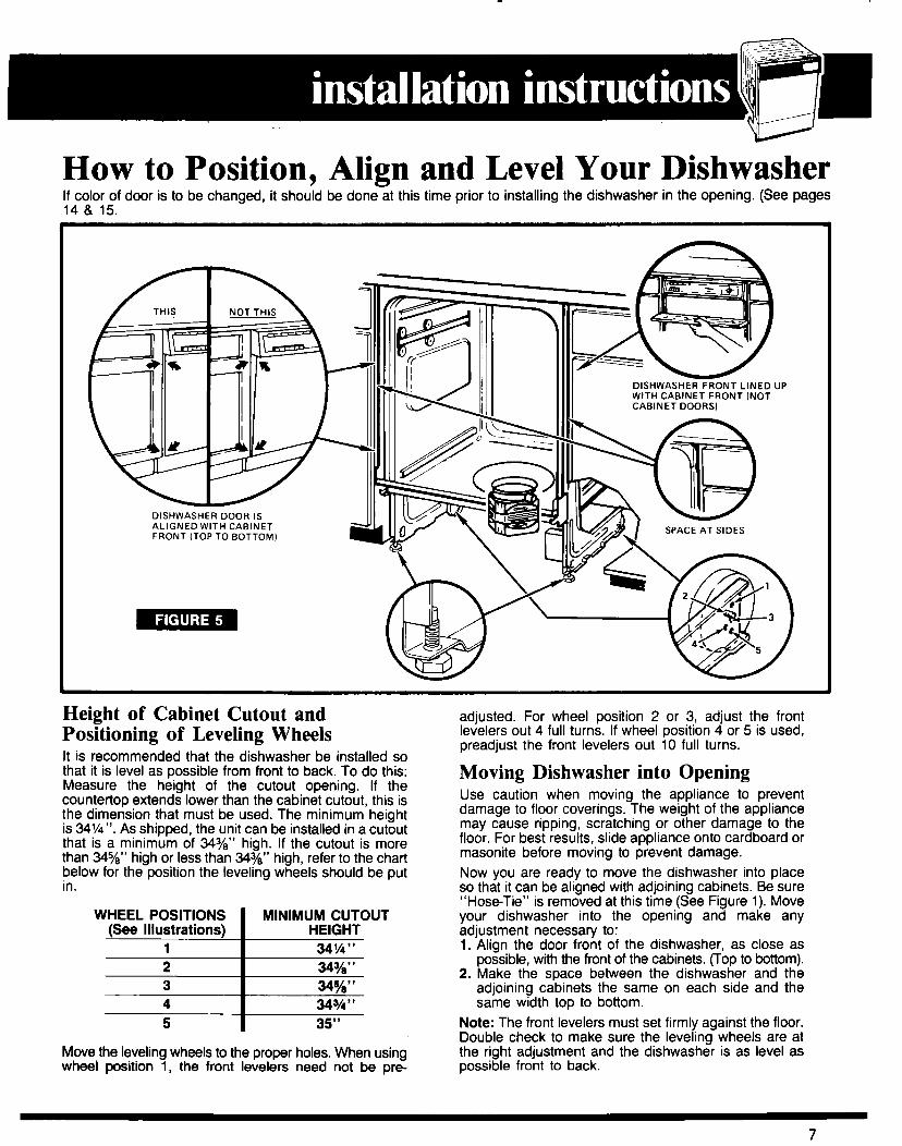
How to Position, Align and Level Your Dishwasher If color of door is to be changed, it should be done at this time prior to installing the dishwasher in the opening. (See pages 14 8 15.
Height of Cabinet Cutout and Positioning of Leveling Wheels It is recommended that the dishwasher be installed so that it is level as possible from front to back. To do this: Measure the height of the cutout opening. If the countertop extends lower than the cabinet cutout, this is the dimension that must be used. The minimum height is 34%“. As shipped, the unit can be installed in a cutout that is a minimum of 343/e” high. If the cutout is more than 3445/e” high or less than 34Yo” high, refer to the chart below for the position the leveling wheels should be put in.
5 I 35”
Move the leveling wheels to the proper holes. When using wheel position 1, the front levelers need not be pre-
adjusted. For wheel position 2 or 3, adjust the front levelers out 4 full turns. If wheel position 4 or 5 is used, preadjust the front levelers out 10 full turns.
Moving Dishwasher into Opening Use caution when moving the appliance to prevent damage to floor coverings. The weight of the appliance may cause ripping, scratching or other damage to the floor. For best results, slide appliance onto cardboard or masonite before moving to prevent damage. Now you are ready to move the dishwasher into place so that it can be aligned with adjoining cabinets. Be sure “Hose-Tie” is removed at this time (See Figure 1). Move your dishwasher into the opening and make any adjustment necessary to: 1. Align the door front of the dishwasher, as close as
possible, with the front of the cabinets. (Top to bottom). 2. Make the space between the dishwasher and the
adjoining cabinets the same on each side and the same width top to bottom.
Note: The front levelers must set firmly against the floor. Double check to make sure the leveling wheels are at the right adjustment and the dishwasher is as level as possible front to back.
7
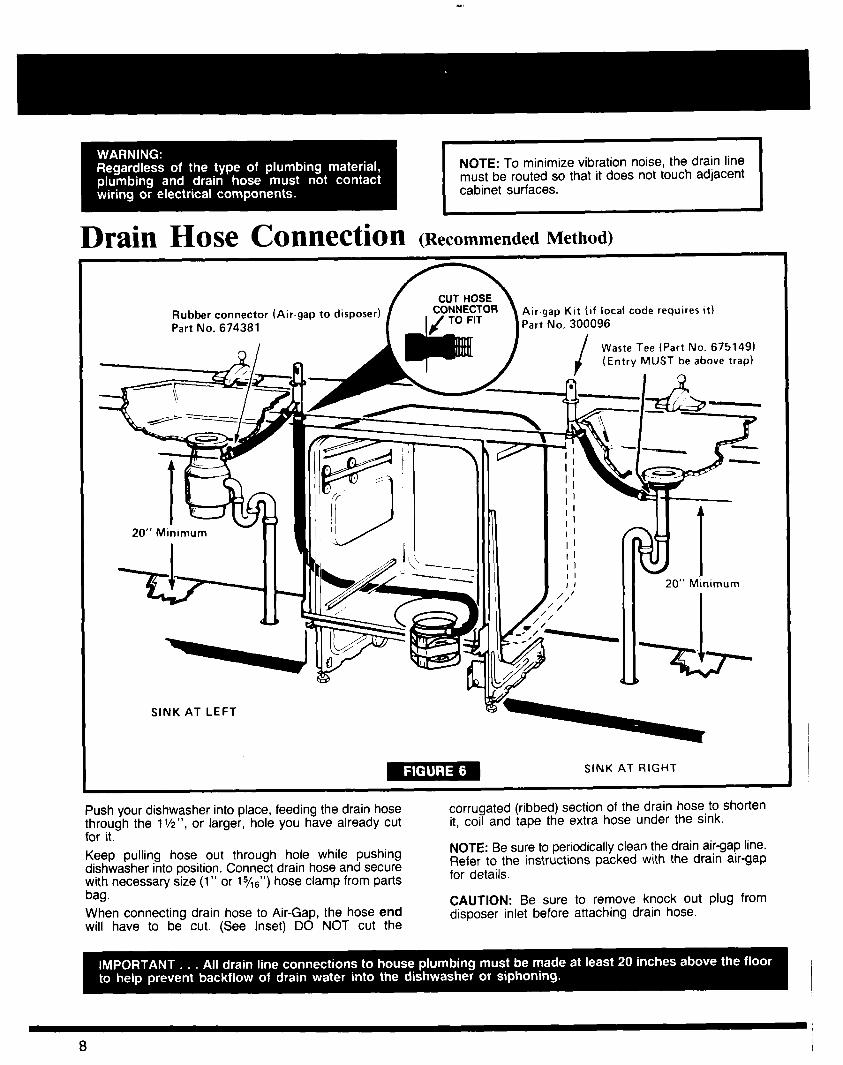
NOTE: To minimize vibration noise, the drain line must be routed so that it does not touch adjacent
Drain Hose cOntWi!tiOn (Recommended Method)
/lb Rubber connector (Air-gap to disposer) Part No. 674381
Air.gap Kit (if local code requires it) Part No. 300096
Waste Tee (Part No. 675149) (Entry MUST be above trap)
I I 20” Minimum
SINK AT LEFT
- SINK AT RIGHT
Push your dishwasher into place, feeding the drain hose corrugated (ribbed) section of the drain hose to shorten through the 11/2", or larger, hole you have already cut it, coil and tape the extra hose under the sink. for it. Keep pulling hose out through hole while pushing dishwasher into position. Connect drain hose and secure with necessary size (1” or 15/16”) hose clamp from parts
NOTE: Be sure to periodically clean the drain air-gap line. Refer to the instructions packed with the drain air-gap for details.
bag. When connecting drain hose to Air-Gap, the hose end will have to be cut. (See Inset) DO NOT cut the
CAUTION: Be sure to remove knock out plug from disposer inlet before attaching drain hose.
Waste Tee (Part NO. 675149) ,C-.*., MI IST above traoi
w-- 0
\
I L/ 20”
Minimum / Trap
#j/ -
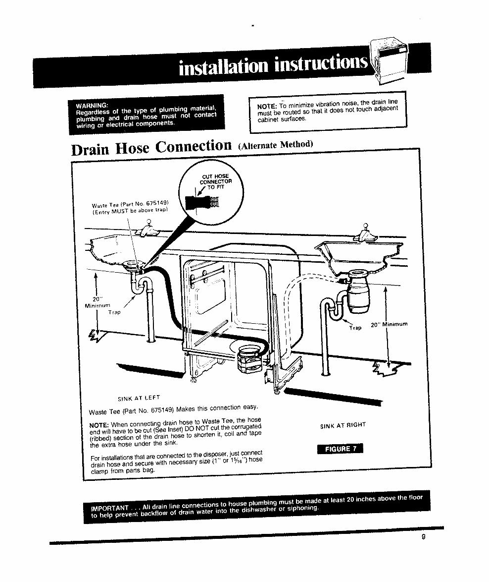
NOTE: To minimize vibration noise, the drajn line must be routed so that it does not touch adjacent cabinet surfaces.
.==ykt33--
z Trap 20” Minimum
I
I
Drain Hose COl3neCtiOn (Alternate Method)
SINK AT LEFT
Waste Tee (Part No. 675149) Makes this connection easy.
NOTE: When connecting drain hose to Waste Tee, the hose end will have to be cut (See Inset) DO NOT cut the corrugated (ribbed) section of the drain hose to shorten it, coil and tape the extra hose under the sink.
For installations that are connected to the disposer, just Connect drain hose and secure with necessary size (1” or 1%“) hose clamp from parts bag.
SINK AT RIGHT
Rmlim
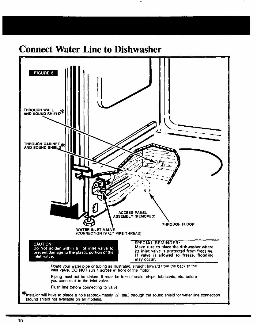
Connect Water Line to Dishwasher
ACCESS PANEL
\ ASSEMBLY (REMOVED)
7 \ THROUGh FLOOR
WATER INLET VALVE (CONNECTION IS s” PIPE THREAD)
SPECIAL REMINDER: Make sure to place the dishwasher where its inlet valve is protected from freezing. If valve is allowed to freeze, flooding may occur.
Route your water pi inlet valve. DO NO f
e or tubing as illustrated, straight forward from the back to the run it across in front of the motor.
Piping must not be kinked. It must be free of scale, chips, lubricants, etc. before you connect it to the inlet valve.
Flush line before connecting to valve.
* Installer will have to pierce a hole (approximately l/z” dia.) through the sound shield for water line connection (sound;shield not available on all models).
-
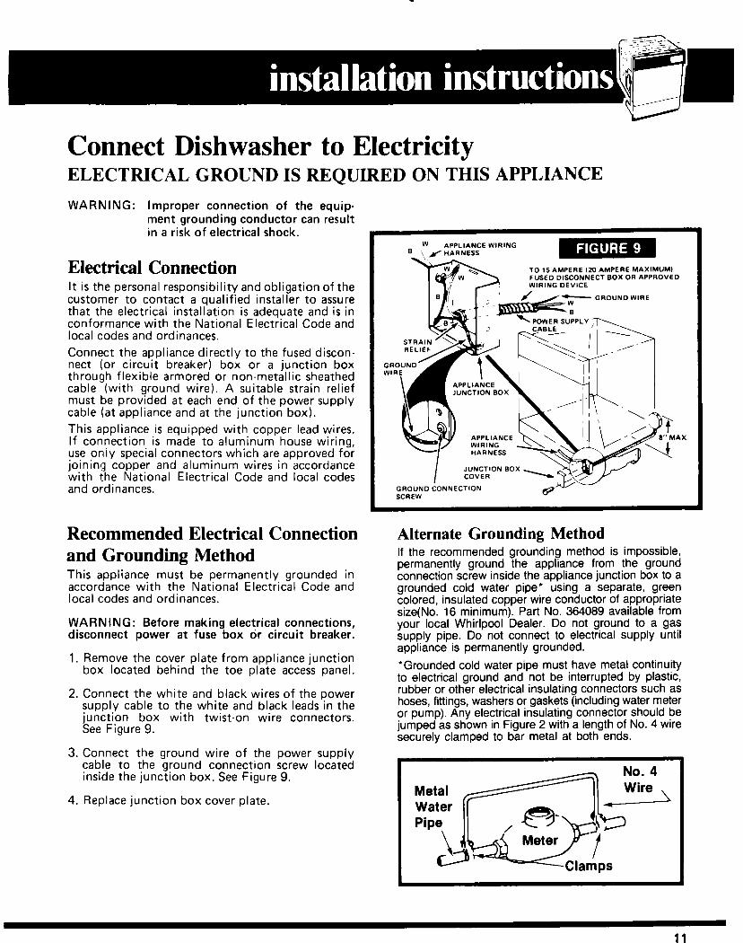
Connect Dishwasher to Electricity ELECTRICAL GROUND IS REQUIRED ON THIS APPLIANCE
WARNING: Improper connection of the equip- ment grounding conductor can result in a risk of electrical shock.
Electrical Connection It is the personal responsibility and obligation of the customer to contact a qualified installer to assure that the electrical installation is adequate and is in conformance with the National Electrical Code and local codes and ordinances. Connect the appliance directly to the fused discon- nect (or circuit breaker) box or a junction box through flexible armored or non-metallic sheathed cable (with ground wire). A suitable strain relief must be provided at each end of the power supply cable (at appliance and at the junction box). This appliance is equipped with copper lead wires. If connection is made to aluminum house wiring, use oniy special connectors which are approved for joining copper and aluminum wires in accordance with the National Electrical Code and local codes and ordinances.
Recommended Electrical Connection and Grounding Method This appliance must be permanently grounded in accordance with the National Electrical Code and local codes and ordinances.
WARNING: Before making electrical connections, disconnect power at fuse box or circuit breaker.
1. Remove the cover plate from appliance junction box located behind the toe plate access panel.
2. Connect the white and black wires of the power supply cable to the white and black leads in the junction box with twist-on wire connectors. See Figure 9.
3. Connect the ground wire of the power supply cable to the ground connection screw located inside the junction box. See Figure 9.
4. Replace junction box cover plate.
W APPLIANCE WIRING
TO 15 AMPERE 120 AMPERE MAXIMUMI FUSED DISCONNECT BOX OR APPROVED WIRING DEVICE
GROUND WIRE
POWER SUPPLY
APPLIANCE AX.
JUNCTION BOX
SCREW v
Alternate Grounding Method If the recommended grounding method is impossible, permanently ground the appliance from the ground connection screw inside the appliance junction box to a grounded cold water pipe* using a separate, green colored, insulated copper wire conductor of appropriate size(No. 16 minimum). Part No. 364089 available from your local Whirlpool Dealer. Do not ground to a gas supply pipe. Do not connect to electrical supply until appliance is permanently grounded.
*Grounded cold water pipe must have metal continuity to electrical ground and not be interrupted by plastic, rubber or other electrical insulating connectors such as hoses, fittings, washers or gaskets (including water meter or pump). Any electrical insulating connector should be jumped as shown in Figure 2 with a length of No. 4 wire securely clamped to bar metal at both ends.
11
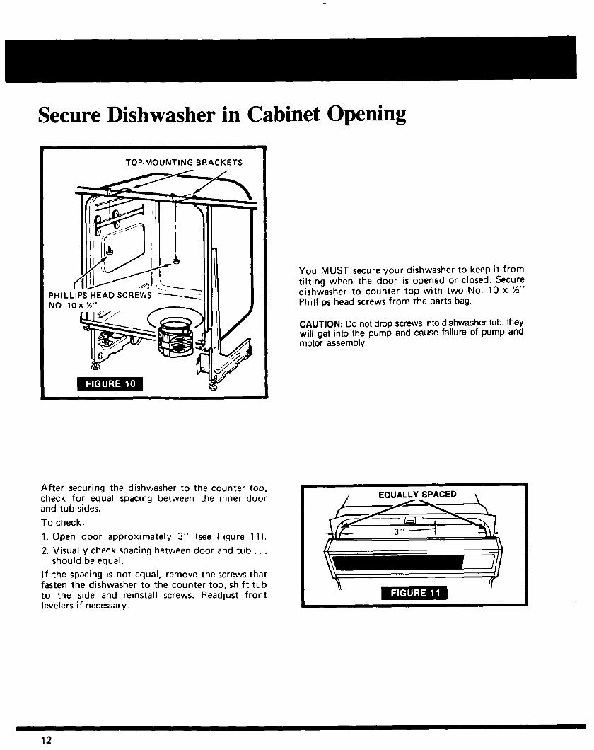
Secure Dishwasher in Cabinet Opening
TOP-MOUNTING BRACKETS
After securing the dishwasher to the counter top, check for equal spacing between the inner door and tub sides.
To check:
1. Open door approximately 3” (see Figure 11).
2. Visually check spacing between door and tub . . . should be equal.
If the spacing is not equal, remove the screws that fasten the dishwasher to the counter top, shift tub to the side and reinstall screws. Readjust front levelers if necessary.
You MUST secure your dishwasher to keep it from tilting when the door is opened or closed. Secure dishwasher to counter top with two No. 10 x %” Phillips head screws from the parts bag.
CAUTION: Do not drop screws into dishwasher tub, they will get into the pump and cause failure of pump and motor assembly.
Itil II I
12

Installation and Operation. . .
Double Check 1/ If 0 Securely fastened in place. 0 Water supply valve turned on. 0 Checked out for leaks at joints.
\. 0 Wire connections tight, water inlet valve wiring in place. 0 Make certain electricity is turned on.
@
0 No kinks in water line.
1 0 Recheck the removal of packing material and Customer Literature
Package from interior of dishwasher. -17,
/y-u’ 0 Spin spray arms to check movement.
7/- 3 0 Start dishwasher. 0 Check water level . , . water should fill to the round heater element. 0 Check for complete drain . no water should be visible above
grate when drain is complete. 0 Check for leaks . . - particularly around door, pum.p mounting
gasket, and at hose connections. Also the plumbing connection at the water inlet valve.
NOTE TO INSTALLER: Put Installation Instruction back in Literature Package and place inside dishwasher so that all information will be readily available to the user.
Adjust Door Springs and Install Access Panel
(Less tension)
Dishwasher leg
After dishwasher has been secured in the cabinet opening, check door for proper operation. If adjustment is necessary, close door and adjust door springs with pliers so door closes easily without slamming and stays open with its own weight. See Figure 12. Install the access panel by using the 4 screws that were removed (2 screws on each end). (See Figure 13)
13
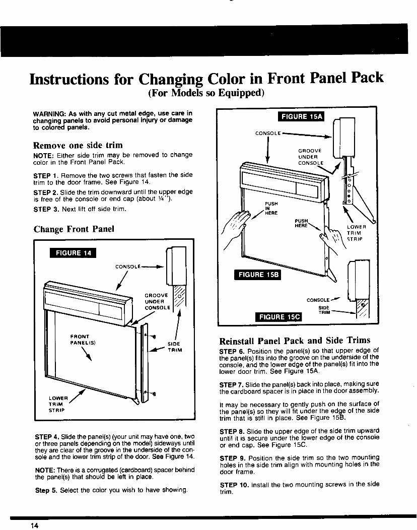
Instructions for Changing Color in Front Panel Pack (For Modek so Equipped)
WARNING: As with any cut metal edge, use care in changing panels to avoid personal injury or damage to colored panels.
Remove one side trim NOTE: Either side trim may be removed to change color in the Front Panel Pack.
STEP 1. Remove the two screws that fasten the side trim to the door frame. See Figure 14.
STEP 2. Slide the trim downward until the upper edge is free of the console or end cap (about VI”).
STEP 3. Next lift off side trim.
Change Front Panel
CONSOLE- m
STRIP
STEP 4. Slide the panel(s) (your unit may have one, two or three panels depending on the model) sideways until they are clear of the groove in the underside of the con- sole and the lower trim strip of the door. See Figure 14.
NOTE: There is a corrugated (cardboard) spacer behind the panel(s) that should be left in place.
Step 5. Select the color you wish to have showing.
CONSOLE L-+
I GROOVE l-n
1 LOWER TRIM STRIP
Reinstall Panel Pack and Side Trims STEP 6. Position the panel(s) so that upper edge of the panel(s) fits into the groove on the underside of the console, and the lower edge of the panel(s) fit into the lower door trim. See Figure 15A.
STEP 7. Slide the panel(s) back into place, making sure the cardboard spacer is in place in the door assembly.
It may be necessary to gently push on the surface of the panel(s) so they will fit under the edge of the side trim that is still in place. See Figure 158.
STEP 6. Slide the upper edge of the side trim upward until it is secure under the lower edge of the console or end cap. See Figure 1X.
STEP 9. Position the side trim so the two mounting holes in the side trim align with mounting holes in the door frame.
STEP 10. Install the two mounting screws in the side trim.
14
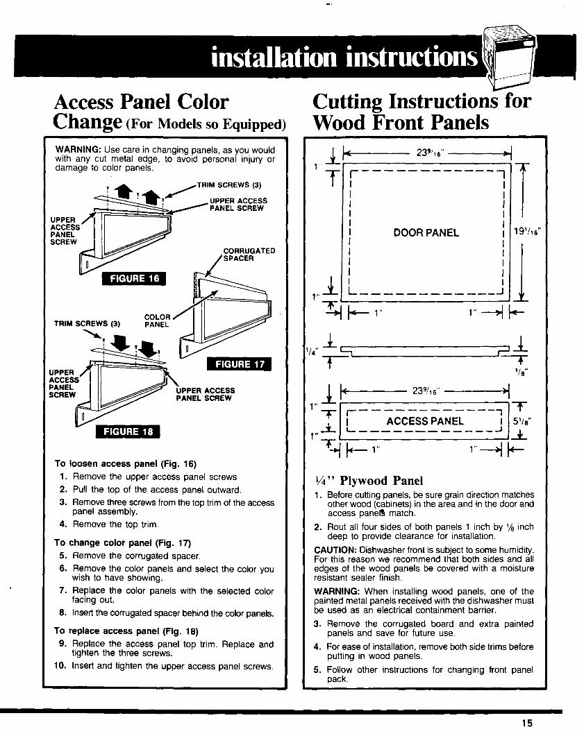
Access Panel Color Change (For Models SO Equipped)
WARNING: Use care in changing panels, as you would with any cut metal edge, to avoid personal injury or damage to color panels.
TRIM SCREWS (3)
UPPER ACCESS PANEL SCREW
To loosen access panel (Fig. 16) 1. Remove the upper access panel screws 2. Pull the top of the access panel outward. 3. Remove three screws from the top trim of the access
panel assembly. 4. Remove the top trim.
To change color panel (Fig. 17) 5. Remove the corrugated spacer. 6. Remove the color panels and select the color you
wish to have showing. 7. Replace the color panels with the selected color
facing out. 8. Insert the corrugated spacer behind the color panels.
To replace access panel (Fig. 18) 9. Replace the access panel top trim. Replace and
tighten the three screws. 10. Insert and tighten the upper access panel screws.
Cutting Instructions for Wood Front Panels
,/,” Plywood Panel 1. Before cutting panels, be sure grain direction matches
other wood (cabinets) in the area and in the door and access panelg match.
2. Rout all four sides of both panels 1 inch by l/e inch deep to provide clearance for installation.
CAUTION: Dishwasher front is subject to some humidity. For this reason we recommend that both sides and all edges of the wood panels be covered with a moisture resistant sealer finish.
WARNING: When installing wood panels, one of the painted metal panels received with the dishwasher must be used as an electrical containment barrier.
3. Remove the corrugated board and extra painted panels and save for future use.
4. For ease of installation, remove both side trims before putting in wood panels.
5. Follow other instructions for changing front panel pack.
15

Part No. 304417 Rev. B
Making your world a little easier.
In the event your WHIRLPOOL appliance should need service, cell the dealer from whom you purchased the appliance or a WHIRLPOOL franchised TECH-CARE@ service company. He is in the Yellow Pages of your telephone directory listed under “Appliances-Household-Major.Service and Repair.” You can also obtain his name and number by dialing, free, within the continental United States the Whirlpool COOL-LINE@ Service (800) 253.1301. When calling from Michigan, dial (800) 632.2243; from Alaska or Hawaii, dial (800) 253-1121. Dial just as you normally dial long distance. A special operator will tell you the name and number of your nearest Whirlpool TECH-CARE service outlet. During normal working hours. Whirlpool consultants at this same number will also answer any questions about operating or maintaining your appliance not covered in your Use and Care Guide.
Learn the benefits of using TECH-CARE service for maintaining the quality originally built into your WHIRLPOOL appliance.
Printed in U.S.A.
ifiers, Automatic Washers, Clothes Dryers, Freezers, Refrigerator-Freezers, Ice Makers, Dishwashers, Built-In Ovens and Surface Units, Ranges, Microbial