Embed Size (px)
Citation preview
SWISSPHONE Telecom AG Fälmisstrasse 21 I-SEARCH System Description Version 3.2.0 english.doc CH-8833 Samstagern
System Description
Version 3.2.0
I.SEARCH System Description
Version 3.2.0 2/57
Versions Verification
Author Version Date Comments
Nadine Inderbitzin 3.0.1 5.3.2008 Formatting
Patrick Utzinger 3.1.0 27.3.2008 Common revision
Patrick Utzinger 3.2.0 5.6.2008 2, 3.10, 7.2, 8

I.SEARCH System Description
Version 3.2.0 3/57
Contents
1. Introduction 7
2. I.SEARCH Models 9
2.1. The I.SEARCH 200 Class (only on request) 9
2.2. The I.SEARCH 500 Class 9
2.3. The I.SEARCH 400 Class (only on request) 9
3. Hardware 9
3.1. Base System 9
3.2. Computer 9
3.3. Network port 9
3.4. Power Supply 9
3.5. Network Input Module 9
3.6. Power Cable 10
3.7. Protection System (ESD) 10
3.8. GSM Modem Option 10
3.9. 16x I/O Module Option 10
3.10. Transmitter Option 10
3.10.1. Transmitter 10
3.10.2. Antenna system 10
3.10.3. Indoor Antenna 10
3.10.4. Outdoor Antenna 10
3.11. WD2000 Watchdog Module Option 10
3.12. Case Options 11
3.12.1. Desktop Case (only on request) 11
3.12.2. 19" Rack 11
3.12.3. ITC2000 Case (until 2008) 12
3.13. Hardware Configuration 13
3.13.1. I.SEARCH 200 Desktop Case 13
3.13.2. I.SEARCH 500 19" Rack 14
3.13.3. 19“Rack ITC2000 with I.SEARCH 500 15
I.SEARCH System Description
Version 3.2.0 4/57
4. Functional Description: General Information 16
5. Input Modules 17
5.1. Browser Access 18
5.1.1. General Information 18
5.1.2. User Permissions 19
5.1.3. Direct Messaging 20
5.1.4. Administrator Configuration Management 21
5.2. Private Branch Exchange (PBX) Interfaces 21
5.2.1. DTMF 21
5.2.2. ESPA 4.4.3 22
5.2.3. ESPA 4.4.4 23
5.2.4. CSTA 23
5.3. Automatic Messaging 23
5.3.1. Potential-free Contacts 23
5.3.2. Serial Interface 24
5.3.3. SMTP Interface 24
5.3.4. Server Monitoring 25
5.3.5. MIP11 Plus 25
5.4. SNMP-Traps 26
5.5. E-Mail Messaging 26
6. Processing Modules 27
6.1. User Groups 27
6.1.1. Active Users 27
6.1.2. Passive User 27
6.2. Processing Input Messages 28
6.2.1. Messages to Passive Individual Users 28
6.2.2. Messages to Passive Group Users 28
6.3. Time and Absence Management 28
6.4. Escalation Management (on request) 32
6.4.1. Escalation 32
6.4.2. Acknowledgement process 34
6.5. System Utilities 35

I.SEARCH System Description
Version 3.2.0 5/57
6.5.1. System Configuration 35
6.5.2. User Administration 35
6.5.3. User Administration with CSV Files 36
6.5.4. Using Additional Fields 36
6.5.5. Operational Analysis and Error Management 37
6.5.6. Backup and Restore Operations 37
6.5.7. Log File Export Operations 37
6.5.8. Remote Access 38
6.6. High Availability Cluster 38
7. Output Modules 39
7.1. General Information 39
7.2. On-Site Paging 39
7.2.1. Transmitters 40
7.3. IDEA Encryption 48
7.4. Over Air Programming (OAP) 48
7.5. On-Site Pagers 48
7.6. Off-Site Messaging 48
7.6.1. ISDN Output 48
7.6.2. PSTN Analogue Telephony Output 49
7.6.3. Internet Output 49
7.6.4. Sending SMS Messages with the GSM Module 50
7.6.5. Sending E-Mail 50
7.7. Off-Site Devices 51
7.8. System output 51
7.8.1. System Monitoring and Alarm 51
7.8.2. Log Books 51
7.8.3. Raw Statistical Data 51
7.8.4. Lists 51
8. Accessories 52
8.1. LAN Converter I.COM 52
8.1.1. 19" Installation 52
8.2. Monitorstation MS2100 52
I.SEARCH System Description
Version 3.2.0 6/57
8.2.1. Konfiguration 53
8.3. Multi Charger Rack MCR 53
8.3.1. Konfiguration 53
8.4. LAN-Eingänge "Sealevel" 53
8.4.1. Contact Input 54
8.4.2. 19" Installation 54
9. Glossary 54
10. Technical Specifications 56
I.SEARCH System Description
Version 3.2.0 7/57
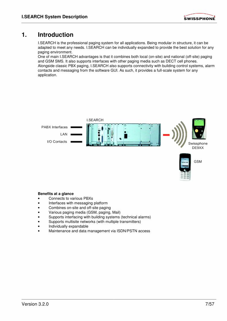
1. Introduction
I.SEARCH is the professional paging system for all applications. Being modular in structure, it can be
adapted to meet any needs. I.SEARCH can be individually expanded to provide the best solution for any
paging environment.
One of main I.SEARCH advantages is that it combines both local (on-site) and national (off-site) paging
and GSM SMS. It also supports interfaces with other paging media such as DECT cell phones.
Alongside classic PBX paging, I.SEARCH also supports connectivity with building control systems, alarm
contacts and messaging from the software GUI. As such, it provides a full-scale system for any
application.
Benefits at a glance
• Connects to various PBXs
• Interfaces with messaging platform
• Combines on-site and off-site paging
• Various paging media (GSM, paging, Mail)
• Supports interfacing with building systems (technical alarms)
• Supports multisite networks (with multiple transmitters)
• Individually expandable
• Maintenance and data management via ISDN/PSTN access

I.SEARCH System Description
Version 3.2.0 8/57
Software features
• Direct messaging
• E-mail messaging
• Supports PBX paging processes
• Automatic messaging (alarm and information server)
• Subscriber data management
• Various user levels
• Imports and exports user data (CSV file)
• Exports log files (CSV file)
• Local configuration from any office PC (browser GUI)
• Escalation module
• Absence management
• Work and time schedules
• etc.
Alarm module
I.SEARCH offers various input modules for alarm points:
• 32 floating contacts
• Cascadable modules
• Local contacts (accessible via LANs)
Web interface
I.SEARCH can be fully operated and configured from an internet browser (e.g., Microsoft Internet
Explorer, Netscape) installed on any PC in the intranet. The web interface offers easy, intuitive handling
and does not require special hardware or software. That means that no additional system monitors are
required.
• Browser GUI
• 8 different user levels (user, support, admin, etc.)
• Local management and system input
• Imports and exports user data (CSV file)
• Exports log files (CSV file)
• System monitoring
• Direct messaging
PBX interfaces (personal branch exchange)
There are 3 interfaces providing connectivity to PBXs
• ESPA 4.4.3 (supports up to 6 interfaces with external hardware)
• ESPA 4.4.4
• CSTA (upon request; depends on PBX)
• Special protocols available upon request
On-site messaging (local)
• 4W or 25W transmitters
• Paging frequencies (UHF 430-450MHz or 450 – 470MHz in 12.5, 20, 25kHz channel spacing)
• Supports multiple transmitters (via LAN or RS-422/ RS-232)
• POCSAG standard code
Off-site messaging (national)
• Coverage area is dimensioned to suit needs (regional, national, international)
• Messaging platform provides provider access via ISDN or internet (TCP/IP)
• Optional GSM support via messaging platform or internal hardware
Uninterruptible power supply (UPS)
• Continues running during power outages for at least 2 hours
Pagers
Swissphone provides a wide range of digital POCSAG pagers for various needs.
I.SEARCH System Description
Version 3.2.0 9/57
2. I.SEARCH Models
2.1. The I.SEARCH 200 Class (only on request)
I.SEARCH 200 is a preconfigured system in a desktop case. It contains predefined hardware and
software modules. I.SEARCH 200 can go into operation without configuraton.
Exisisting systems extended with additional hardware and software modules. I.SEARCH 200 uses the
same software as I.SEARCH 500.
2.2. The I.SEARCH 500 Class
I.SEARCH 500 allows individual solutions. It is modular and flexible enough to be tailored to individual
customer needs. Some engineering is usually required to adapt the system to local conditions.
I.SEARCH 500 consists of various hardware and software modules. Using local module units or 19" rack,
these modules are combined to create the overall system. I.SEARCH 500 uses the same software as
I.SEARCH 200.
2.3. The I.SEARCH 400 Class (only on request)
I.SEARCH 400 is based on standard PC technology and Microsoft Windows.
This document does not describe I.SEARCH 400 . For more information about I.SEARCH 400, please
consult the I.SEARCH 400 documentation (Genius 2000).
3. Hardware
3.1. Base System
The base module consists of a computer and power supply unit. All the electronic components are
contained in a rugged desktop case (I.SEARCH 200) or a 19" rack (I.SEARCH 500). I.SEARCH has a
power connection (230V/50Hz), a network port (10/100BaseT, Ethernet) and several other interfaces for
the system, including an antenna connector (BNC) for attaching a local transmitter.
3.2. Computer
I.SEARCH uses an embedded single board computer. The I.SEARCH configuration requires 64 MB RAM
and a flash disk with minimum256 MB. I.SEARCH. The computer board features an AT-96 bus interface
through which the computer communicates with external hardware components. The board features
additional built-in interfaces such as serial, parallel port, VGA adapter, USB and Ethernet adapter. The
front panel of the computer module has a reset button so you can cold-reset I.SEARCH if it hangs.
The computer module has monitor and keyboard ports, but they are not used because all system
communications are conducted using the network port and a standard browser.
3.3. Network port
The network port is a 16-bit Ethernet port that supports IEEE 802.3-compliant 10Mbps transmission.
The connector is a standard port with an RJ-45 connector.
3.4. Power Supply
The operating voltage is provided by a primary clocked power supply. The output voltages of the power
supply are +5V and ±15V. the input voltage is 230V/50 Hz.
3.5. Network Input Module
The power switch is located on the rear of the network input module on the rear side of the case. It
regulates the phase and the neutral conductor. It also contains 2 fuses.
The switch has been positioned so that outside parties cannot accidentally turn off the system.
I.SEARCH System Description
Version 3.2.0 10/57
3.6. Power Cable
I.SEARCH has a C13 socket for standard power cables. That means the system can be shipped with a
country specific power cable.
3.7. Protection System (ESD)
The system case is connected to mains ground. All system outputs refer to this potential. All external
contacts are separated galvanically.
3.8. GSM Modem Option
The GSM modem option is added to the system using a plug-in unit. The unit consists of a Siemens GSM
RS/TX module and a conversion circuit to the AT-96 bus system. If the system already contains the
SMS/GSM option, there is an FME antenna connection for the GSM antenna.
3.9. 16x I/O Module Option
A plug-in card and an external cross-connect system allow the operation of 16 inputs and outputs. The
cross-connect system can be installed separately (max. 2m).
3.10. Transmitter Option
3.10.1. Transmitter
The transmitters used in I.SEARCH meet the national on-site paging standards (ETSI 300224). The
transmitters are designed to transmit data digitally (POCSAG) and continuous operation. Modulation type
is DFSK by default.
Properties:
• Frequency bands: VHF (66-88MHzor 136-174MHz), UHF (400–470 MHz), programmable
• Output power: 0.1-25W (up to 100W on request), programmable
• Channel spacing: 12.5, 20, 25kHz
• Transfer rate: 512, 1200, 2400bps (normally 1200bps)
3.10.2. Antenna system
The impedance of the antenna must be 50Ω. The antenna must also be specified for the working
frequency. The cable length has an influence on the output power. The shorter the better.
3.10.3. Indoor Antenna
Any omnidirectional antenna can be used in indoor applications. Swissphone recommends antennas from
Kathrein. The antenna should ideally be located in the centre of the company premises.
3.10.4. Outdoor Antenna
Any omnidirectional antenna can be used in outdoor applications. Swissphone recommends antennas
from Kathrein. You will have to follow the standard installation instructions when installing an outdoor
antenna. The antenna should ideally be located in the centre of the company premises.
3.11. WD2000 Watchdog Module Option
The watchdog module monitors the system. If the software/kernel blocks, it will fail to increment a
counter. After 5 minutes of inactivity, the counter will restart the system. A floating contact will also be
opened/closed. The module also monitors the system's various operating voltages. If one of these
voltages fails, a message is sent to the controller, or rather a floating contact is opened or closed.
I.SEARCH System Description
Version 3.2.0 11/57
3.12. Case Options
I.SEARCH is in three different hardware versions available.
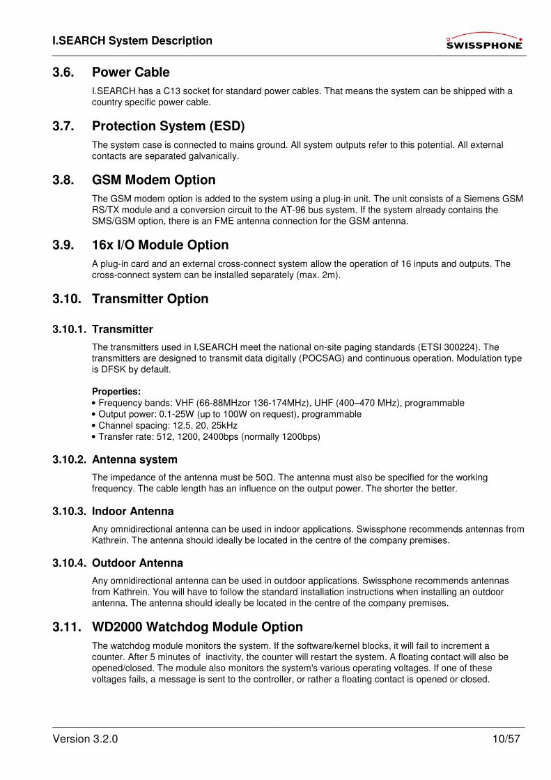
3.12.1. Desktop Case (only on request)
The "Propac" desktop case offers room for 3 additional 4TE optional units besides PC- and power supply
unit.
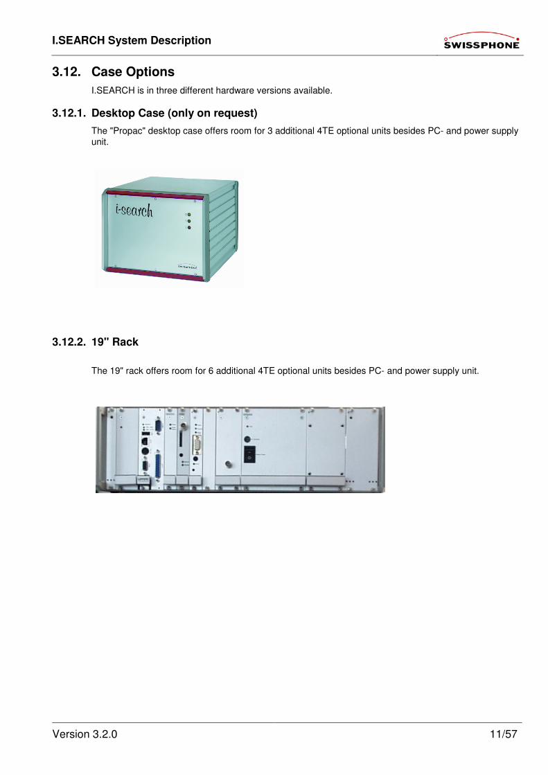
3.12.2. 19" Rack
The 19" rack offers room for 6 additional 4TE optional units besides PC- and power supply unit.
I.SEARCH System Description
Version 3.2.0 12/57
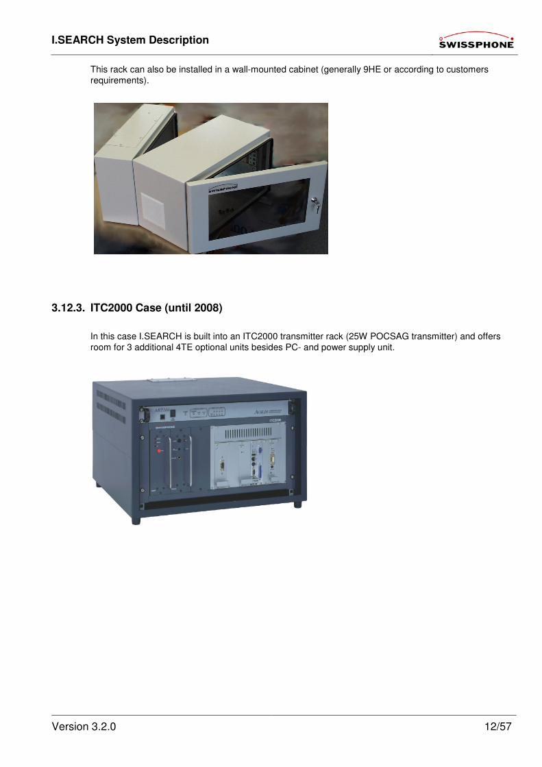
This rack can also be installed in a wall-mounted cabinet (generally 9HE or according to customers
requirements).
3.12.3. ITC2000 Case (until 2008)
In this case I.SEARCH is built into an ITC2000 transmitter rack (25W POCSAG transmitter) and offers
room for 3 additional 4TE optional units besides PC- and power supply unit.
I.SEARCH System Description
Version 3.2.0 13/57
3.13. Hardware Configuration
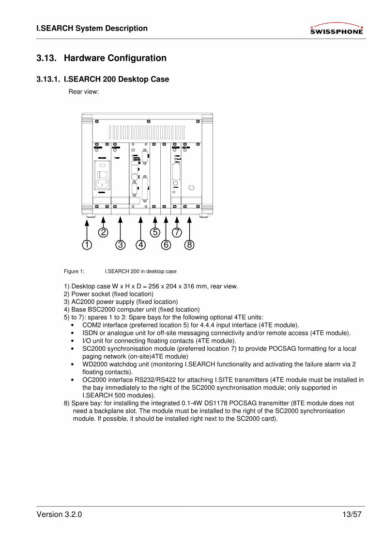
3.13.1. I.SEARCH 200 Desktop Case
Rear view:
Figure 1: I.SEARCH 200 in desktop case
1) Desktop case W x H x D = 256 x 204 x 316 mm, rear view.
2) Power socket (fixed location)
3) AC2000 power supply (fixed location)
4) Base BSC2000 computer unit (fixed location)
5) to 7): spares 1 to 3: Spare bays for the following optional 4TE units:
• COM2 interface (preferred location 5) for 4.4.4 input interface (4TE module).
• ISDN or analogue unit for off-site messaging connectivity and/or remote access (4TE module).
• I/O unit for connecting floating contacts (4TE module).
• SC2000 synchronisation module (preferred location 7) to provide POCSAG formatting for a local
paging network (on-site)4TE module)
• WD2000 watchdog unit (monitoring I.SEARCH functionality and activating the failure alarm via 2
floating contacts).
• OC2000 interface RS232/RS422 for attaching I.SITE transmitters (4TE module must be installed in
the bay immediately to the right of the SC2000 synchronisation module; only supported in
I.SEARCH 500 modules).
8) Spare bay: for installing the integrated 0.1-4W DS1178 POCSAG transmitter (8TE module does not
need a backplane slot. The module must be installed to the right of the SC2000 synchronisation
module. If possible, it should be installed right next to the SC2000 card).
1 8
7
6
5
43
2
I.SEARCH System Description
Version 3.2.0 14/57
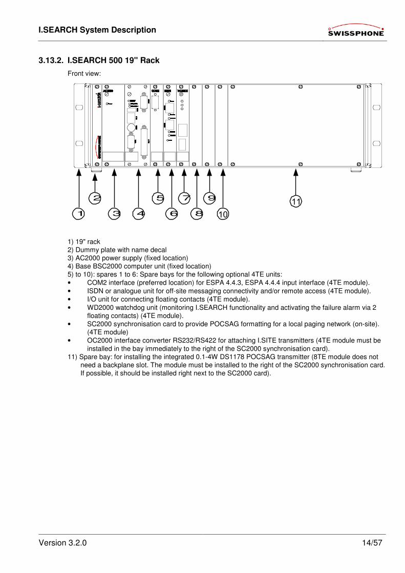
3.13.2. I.SEARCH 500 19" Rack
Front view:
1
9
8
7
6
5
43
2
10
11
1) 19" rack
2) Dummy plate with name decal
3) AC2000 power supply (fixed location)
4) Base BSC2000 computer unit (fixed location)
5) to 10): spares 1 to 6: Spare bays for the following optional 4TE units:
• COM2 interface (preferred location) for ESPA 4.4.3, ESPA 4.4.4 input interface (4TE module).
• ISDN or analogue unit for off-site messaging connectivity and/or remote access (4TE module).
• I/O unit for connecting floating contacts (4TE module).
• WD2000 watchdog unit (monitoring I.SEARCH functionality and activating the failure alarm via 2
floating contacts) (4TE module).
• SC2000 synchronisation card to provide POCSAG formatting for a local paging network (on-site).
(4TE module)
• OC2000 interface converter RS232/RS422 for attaching I.SITE transmitters (4TE module must be
installed in the bay immediately to the right of the SC2000 synchronisation card).
11) Spare bay: for installing the integrated 0.1-4W DS1178 POCSAG transmitter (8TE module does not
need a backplane slot. The module must be installed to the right of the SC2000 synchronisation card.
If possible, it should be installed right next to the SC2000 card).
I.SEARCH System Description
Version 3.2.0 15/57
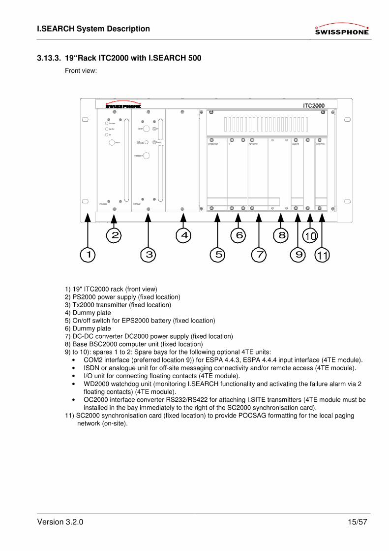
3.13.3. 19“Rack ITC2000 with I.SEARCH 500
Front view:
1 9
8
7
6
5
4
3
2
1) 19" ITC2000 rack (front view)
2) PS2000 power supply (fixed location)
3) Tx2000 transmitter (fixed location)
4) Dummy plate
5) On/off switch for EPS2000 battery (fixed location)
6) Dummy plate
7) DC-DC converter DC2000 power supply (fixed location)
8) Base BSC2000 computer unit (fixed location)
9) to 10): spares 1 to 2: Spare bays for the following optional 4TE units:
• COM2 interface (preferred location 9)) for ESPA 4.4.3, ESPA 4.4.4 input interface (4TE module).
• ISDN or analogue unit for off-site messaging connectivity and/or remote access (4TE module).
• I/O unit for connecting floating contacts (4TE module).
• WD2000 watchdog unit (monitoring I.SEARCH functionality and activating the failure alarm via 2
floating contacts) (4TE module).
• OC2000 interface converter RS232/RS422 for attaching I.SITE transmitters (4TE module must be
installed in the bay immediately to the right of the SC2000 synchronisation card).
11) SC2000 synchronisation card (fixed location) to provide POCSAG formatting for the local paging
network (on-site).
I.SEARCH System Description
Version 3.2.0 16/57
4. Functional Description: General Information
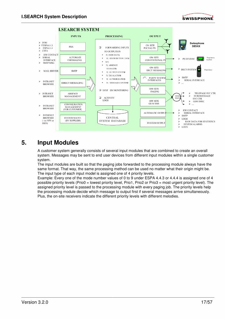
The functionality of I.SEARCH breaks down into the functional blocks shown in the following block
diagram.
I.SEARCH offers the following features:
• International radio and security standards (CE standards).
• Multilingual operation in English, French and German. Additional languages can be easily added if
needed (order guarantee).
• Large call volume must be processable as quickly as possible in accordance with customer
requirements.
• No hard disk for enhanced security.
• Optional independent power supply (UPS) for all system components (including transmitter) for at
least 1 hour.
• To distribute the OFF-site messages to any destination receiver - Euromessage or TELEPAGE
pager, GSM cell phone, etc. - the message data units (at least for the Swiss market) should be
routed to a Swissphone platform. From there, they will then be routed to the various service
centres. The access networks (ISDN, PSDN, INTERNET) between the customer's system and the
Swissphone platform should be selectable based on the customer's system. An alternative path
supported by the customer's system should also be defined. This alternative path will be used if the
primary access network fails (e.g., primary network = INTERNET, back-up = ISDN).
Special modules like the GSM module can be used when needed for the international market so
the messages can be transported directly to the destination network.
• Connects to the intranet in accordance with the customer's IT operating policy framework.
Uses the following TCP/IP ports:
• Port 21 (FTP)
• Port 23 (Telnet)
• Port 25 (SMTP)
• Port 80 (HTTP)
• Port 6611 (I.SEARCH port for a master-slave configuration; see chapter 7.2.4 Master-
slave transmission in this document)
• System monitoring and local alarm (triggering visual and/or audible alarm features).
• Remote access via ISDN or PSTN (using call-back methods) for system maintenance.
• Supports expansions for future, as yet undefined input and output systems.
I.SEARCH System Description
Version 3.2.0 17/57
5. Input Modules
A customer system generally consists of several input modules that are combined to create an overall
system. Messages may be sent to end user devices from different input modules within a single customer
system.
The input modules are built so that the paging jobs forwarded to the processing module always have the
same format. That way, the same processing method can be used no matter what their origin might be.
The input type of each input model is assigned one of 4 priority levels.
Example: Every one of the mode number values of 0 to 9 under ESPA 4.4.3 or 4.4.4 is assigned one of 4
possible priority levels (Prio0 = lowest priority level, Prio1, Prio2 or Prio3 = most urgent priority level). The
assigned priority level is passed to the processing module with every paging job. The priority levels help
the processing module decide which message to output first if several messages arrive simultaneously.
Plus, the on-site receivers indicate the different priority levels with different melodies.
I.SEARCH System Description
Version 3.2.0 18/57
5.1. Browser Access
5.1.1. General Information
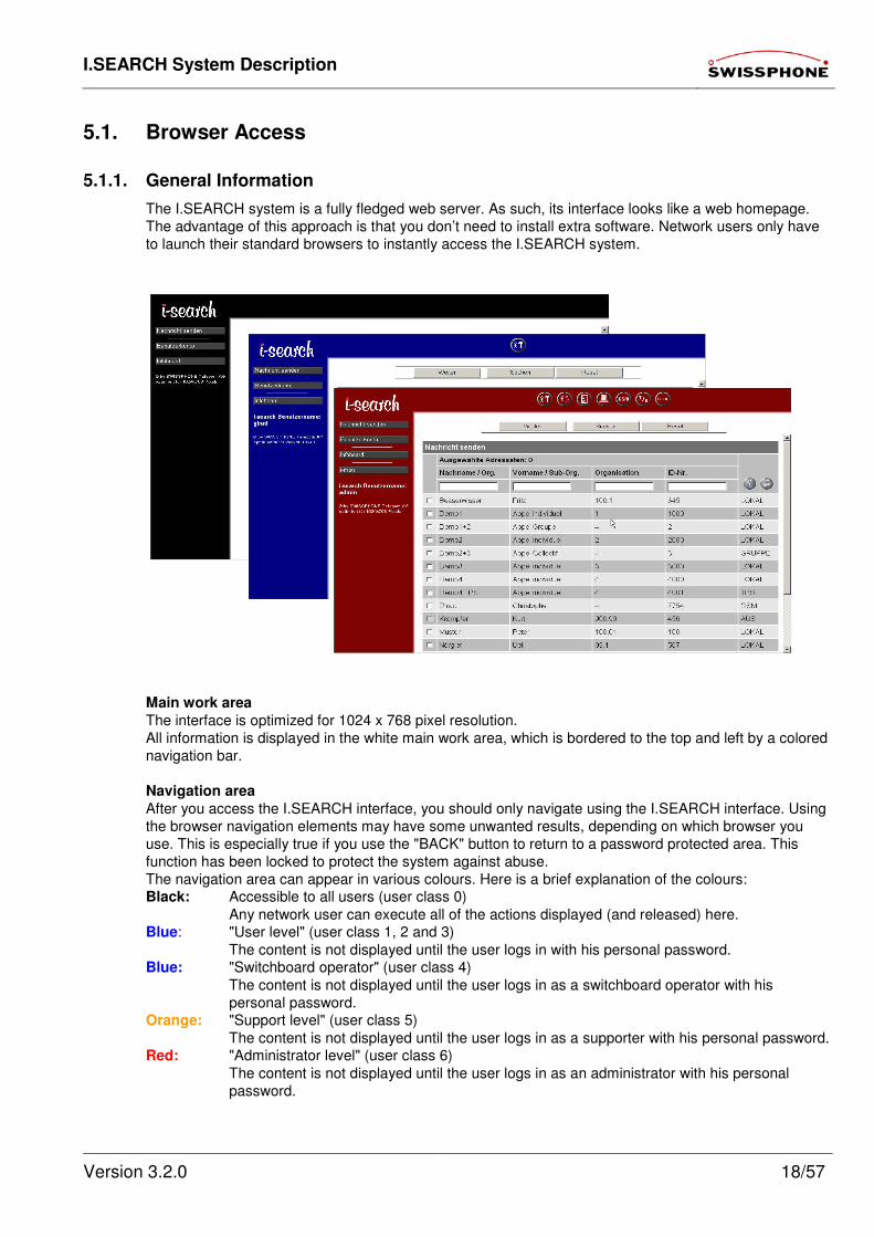
The I.SEARCH system is a fully fledged web server. As such, its interface looks like a web homepage.
The advantage of this approach is that you don’t need to install extra software. Network users only have
to launch their standard browsers to instantly access the I.SEARCH system.
Main work area
The interface is optimized for 1024 x 768 pixel resolution.
All information is displayed in the white main work area, which is bordered to the top and left by a colored
navigation bar.
Navigation area
After you access the I.SEARCH interface, you should only navigate using the I.SEARCH interface. Using
the browser navigation elements may have some unwanted results, depending on which browser you
use. This is especially true if you use the "BACK" button to return to a password protected area. This
function has been locked to protect the system against abuse.
The navigation area can appear in various colours. Here is a brief explanation of the colours: Black: Accessible to all users (user class 0)
Any network user can execute all of the actions displayed (and released) here. Blue: "User level" (user class 1, 2 and 3)
The content is not displayed until the user logs in with his personal password. Blue: "Switchboard operator" (user class 4)
The content is not displayed until the user logs in as a switchboard operator with his
personal password. Orange: "Support level" (user class 5)
The content is not displayed until the user logs in as a supporter with his personal password. Red: "Administrator level" (user class 6)
The content is not displayed until the user logs in as an administrator with his personal
password.
I.SEARCH System Description
Version 3.2.0 19/57
Buttons
The vertical and (possibly) horizontal parts of the navigation area contain buttons. In this document, we
refer to the vertical area as the navigation column, and the horizontal area as the navigation bar. You can
always see the buttons in the navigation column. The buttons in the navigation bar only appear after you
log on.
The I.SEARCH logo (top left) is also a button. Clicking the logo from any page will take you directly to the
I.SEARCH homepage. It also logs you off the I.SEARCH system.
The following buttons are always displayed in the navigation column. The buttons' functionalities are
explained in separate chapters.
Send message
See the "Direct messaging" chapter
User account
Input screen for logging onto the system with your user name and password. When you log onto the
system, it checks what user class you have been assigned. Then, based on your authorization level, it
provides you with your authorized level of functionality.
Infoboard
The Infoboard can be used for community communications. Any network user (from any user class) can
access Infoboard information from the I.SEARCH homepage. The information can be posted and
maintained by various departments. The Infoboard could contain an internal telephone directory, the
weekly cafeteria menu, or any other in-house messages.
Infoboard access privileges are assigned by the administrator using the "Samba" software tool.
Here are some example boards:
• I.SEARCH briefing
• I.SEARCH user manual
• I.SEARCH development team
• Company information
Various pages have an integrated help facility, indicated with a question mark icon.
5.1.2. User Permissions
This feature is part of the I.SEARCH base module.
Active users are people authorized to log into the I.SEARCH system from an office PC within the
customer premises (intranet) using a browser. They are given a user name as well as a password that
they can manage (change) themselves. Their usage permissions are defined and limited in one of 8
possible authorization classes.
The most important of these 8 user classes are:
• System configuration and set-up user. This user is generally a Swissphone employee. This user is
authorized to configure all the system parameters to suit the customer's requirements. This is the
highest authorization class. This user can use all the system's functions.
• The system administrator for configuring user information, time scheduling and absences. This
user is generally one of the customer's employees. This is the 2nd highest authorization class.
• The normal user. These are people in the customer's premises who are authorized to use some of
the system's features. Ideally, this user class should be broken down into several subclasses. For
example, the "normal" user can only set himself as present or absent. A switchboard operator,
however, can change the absence attribute for all users. The system administrator ought to be able
to configure every new user account profile to suit the exact local requirements. Normal users can
be assigned to any of 4 different authorization classes. The customer can also reserve the lowest
authorization class (system parameter), which only entitles the user to access direct messaging.
Users with this authorization level do not need a user name or a password to log in.
I.SEARCH System Description
Version 3.2.0 20/57
• The direct messaging user. These are people in the customer's premises who are only entitled to
use the system's direct messaging function. If requested by the customer (= modifiable system
parameter), these users do not have to log in with user names and passwords. Instead, they
access the direct messaging URL from their (intranet) browser. As such, they do not have to be
registered with the system. That also means that the message originator cannot be identified.
5.1.3. Direct Messaging
This feature is part of the I.SEARCH base module.
The direct messaging module includes:
• Address book with all the names of possible destinations (passive users) that the user is authorized
to send messages to (see table below for more). There is an efficient search procedure (applying
filters to a given address book) to speed up the process of finding a certain name.
• Standard texts in a text library are also available for use (in preparation). The standard texts are
written and defined by active users whose authorization class is 4 or higher.
• Input field for entering messages. Users should see how many characters they have entered so far.
The maximum message length should be limited (parameterizable). Generally, it is set as the
maximum message data unit (MDU) size for all existing output systems. Messages that exceed the
maximum MDU length for the various output systems will be split up into several messages
(separated only at delimiters / blanks, and not within individual words).
• The system immediately displays the positive or negative (with the reason for the obstruction)
acknowledgement of the message.
• The following information is logged in a log book that the administrator can read: entered message
with information on the time, trigger, receiver and the system's positive or negative
acknowledgement. When supplemented with variable parameters (cost centre, organizational
name, personnel number, etc.), the log book can be exported to an external system automatically
according to a preset schedule, or manually based on an administrator command (for internal
accounting or statistical evaluations, etc.).
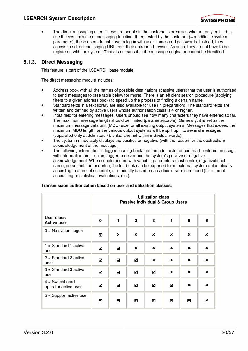
Transmission authorization based on user and utilization classes:
Utilization class
Passive Individual & Group Users
User class
Active user 0 1 2 3 4 5 6
0 = No system logon
1 = Standard 1 active
user
2 = Standard 2 active
user
3 = Standard 3 active
user
4 = Switchboard
operator active user
5 = Support active user
I.SEARCH System Description
Version 3.2.0 21/57
6 = Admin active user
Key:
= Active user can send messages to passive individual and group users.
Passive users with this utilization class are shown in the list of possible destinations.
= Active user cannot send messages to passive individual and group users. Passive users with this
utilization class are not shown in the list of possible destinations.
5.1.4. Administrator Configuration Management
This feature is part of the I.SEARCH base module.
Generally, the I.SEARCH system administrator is one of the customer's employees.
The system administrator logs onto to system by pointing his (intranet) browser to the I.SEARCH
homepage URL and entering his user name and password. The "System configuration" and "System
utilities" chapters of this document describe in detail what configuration settings the administrator can
make.
5.2. Private Branch Exchange (PBX) Interfaces
5.2.1. DTMF
This function is an optional expansion to the I.SEARCH 500 base module (not available with I.SEARCH
200).
I.SEARCH only supports DTMF recognition with the optional PSTN card (ISDN S0 or analogue telephony
unit). The card is connected to the PSTN with an RJ11 connector.
This interface allows a phone line connected to I.SEARCH to place calls from any telephone set and to
send a message (numerals or the number of a predefined standard text) to the end user device of a
person or a group using a telephone keypad (DTMF dialling). This method is used mainly when
I.SEARCH is not connected to a PBX, or when the attached PBX has not implemented the paging
function and thus does not have an ESPA 4.4.3, ESPA 4.4.4 or CSTA interface.
The following format is used to enter messages on a phone keypad:
A identification no. * B telephone no. [* Standard text no.] #
Where:
A identification no.
The destination identification number of the paged party (passive user number)
"*"
Mandatory (DTMF) delimiter
B telephone no.
The phone number for the paging party's phone that the paged party is being asked to dial.
[* Standard text no.]
Standard text parameter identification number after a delimiter [*]. These characters are optional. Optional
characters are indicated with square brackets [ and ]. The standard text parameter identification number
refers to a standard text that has been set in I.SEARCH and that replaces the identification no. in the
transmitted message.
"#"
Pound key (DTMF) is the stop character; it signalizes the end of the DTMF MDU.
I.SEARCH acknowledges the message receipt with a 600ms long 1200Hz tone. Then, I.SEARCH tears
down the call. The paging party can hang up the receiver again (i.e., go on-hook). The paged party now
receives the message "101 (Smith, John) is paging you" on his end user device (pager, GSM, etc.).
I.SEARCH System Description
Version 3.2.0 22/57
If the message text was entered incorrectly, I.SEARCH acknowledges the message with two short 600Hz
tones, each lasting 300ms.
5.2.2. ESPA 4.4.3
This function is an optional expansion to the I.SEARCH 500 base module (not available with I.SEARCH
200).
The ESPA 4.4.3 interface was specified in Publication 4.4.3 (February 1984) of the European Selective
Paging Association (ESPA). It contains the hardware specification (number of connectors, signal levels,
definition of frequencies used, etc.), the necessary data flows (for basic operations between PBXs and
paging systems) as well as the recommended number of ESPA 4.4.3 interfaces relative to the number of
PBX subscribers.
In terms of hardware, the ESPA 4.4.3 interface uses a 2-, 4- or 6-wire E&M line. I.SEARCH supports all
these options. The hardware definition must be parameterized when the system is started up.
All the mode digit values (0 to 9) in the Mode_Digit_1 or Mode_Digit_2 fields can be accepted and
forwarded to the main I.SEARCH module. I.SEARCH can interpret all mode digit values in a given system
and assign each one of them a special meaning for that particular PBX as well as one of 4 possible
priority levels. Depending on the application and the customer's preferences, an optional additional text
that varies from mode digit value to mode digit value can replace the message field content or be added
to it (before or after the effective ESPA 4.4.3 message content).
How many ESPA 4.4.3 interfaces you need to connect depends on the requirements of the individual
customer system. It is also possible to connect several remote PBXs to a single I.SEARCH system using
different ESPA 4.4.3. interfaces, and to operate these PBXs from the single system (request if needed).
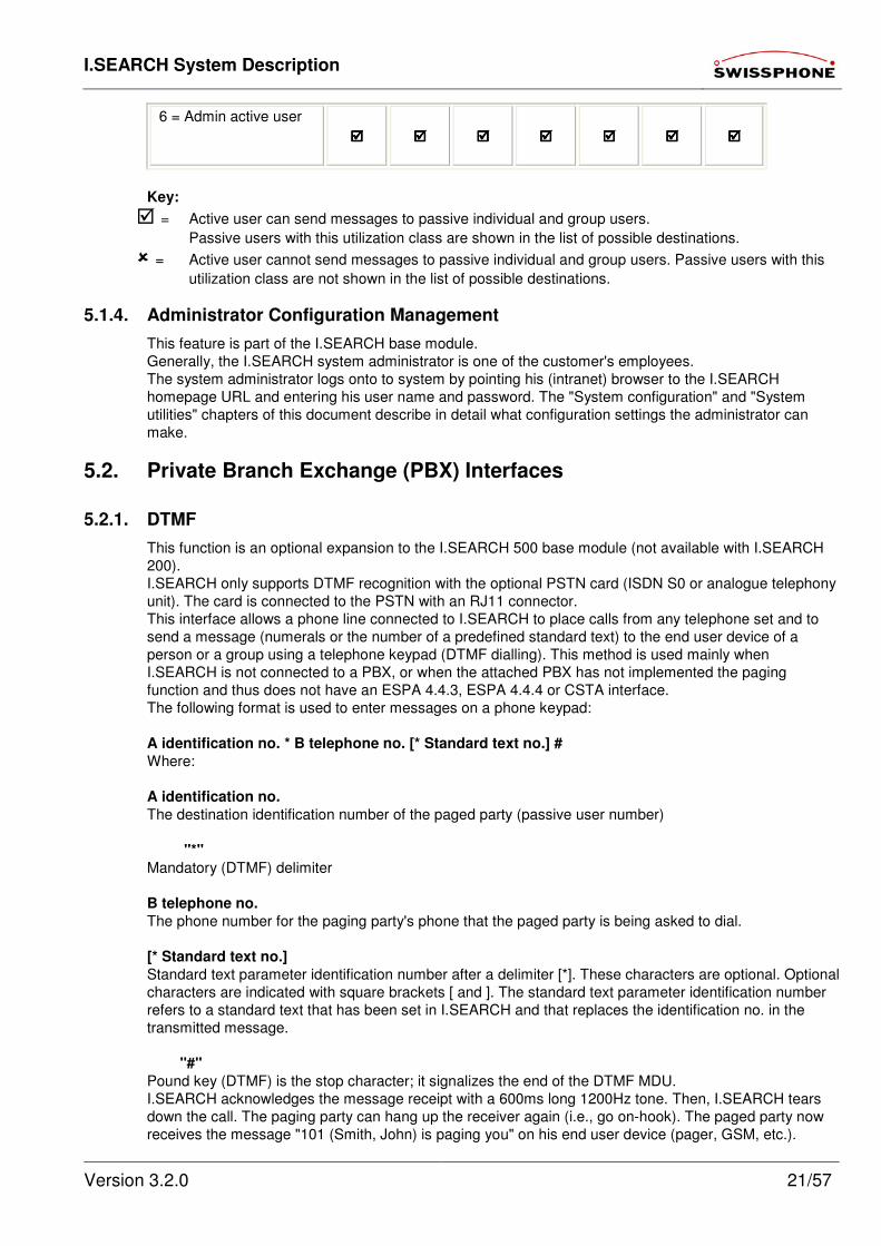
To use ESPA 4.4.3 interfaces, you need a device called an RP201, which is only available with an
I.SEARCH 500 (and not I.SEARCH 200). The RP201 allows you to connect up to 6 different ESPA 4.4.3
circuits to a PBX. The RP201 is responsible for all the handshaking at each ESPA 4.4.3 interface.
Figure 2: I.SEARCH ESPA 4.4.3 interface
ESPA RACK 2 ESPA RACK
PABX (ALL TYPES WITH SERIAL PAGING INTERFACE)
E+M INTERFACE
ES
PA
(4.4
.3)
INTERNAL DIR.NO
EXTERN- TEL.- VERKEHR PSDN
/ ISDN
1 2 3 4 5 6 7 8 9 * 8 #
1 2 3 4 5 6 7 8 9 * 8 #
USER DATA
PBX CONFIG PC
ESPA 4.4.3 - CONTROLLER
RP 201
ESPA 4.4.3 PLUG-IN CARD
ESPA 4.4.3- INTERFACE
E+M INTERFACE
ES
PA
(4.4
.3)
ESPA 4.4.3- INTERFACE
E+M INTERFACE
ES
PA
(4.4
.3)
ESPA 4.4.3 PLUG-IN CARD
ESPA 4.4.3- INTERFACE
E+M INTERFACE
ES
PA
(4.4
.3)
ESPA 4.4.3- INTERFACE
PBX to PBX TEL. TRAFFIC
CONNECTED PBX
Base unit
RS
232
SET UP RP201 (Temporary connection)
I.SEARCH System Description
Version 3.2.0 23/57
5.2.3. ESPA 4.4.4
This feature is an optional expansion module for the I.SEARCH base module.
The ESPA 4.4.4 interface was specified in Publication 4.4.4 of the European Selective Paging
Manufacturers Association (ESPA).
The publication specifies the hardware and data flows (basic operations of MDUs exchanged between the
PBX and the paging system).
The ESPA 4.4.4 interface is based on a serial interface (bit synchronous; character asynchronous
according to ISO 11777; 1 start bit; 7 data bits; even parity; 2 stop bits; 1200bps).
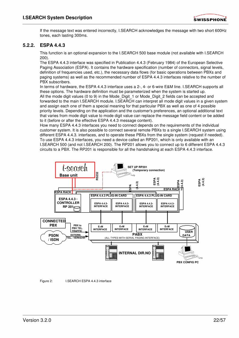
The I.SEARCH computer unit has a COM interface, but it cannot be used as the ESPA 4.4.4 interface.
That is why an additional COM2 interface unit has to be included in I.SEARCH for this function.
If several devices with COM interfaces are attached to I.SEARCH, we recommend using COM servers as
shown below.
As was the case with the ESPA 4.4.3 interfaces, I.SEARCH should be able to interpret and route MDUs
sent from any PBX make and model.
5.2.4. CSTA
This feature is an optional expansion module for the I.SEARCH base module.
The CSTA interface developed in the I.SEARCH project will be used. If necessary, CSTA interfaces for
other PBX vendors can be subsequently developed.
5.3. Automatic Messaging
5.3.1. Potential-free Contacts
This feature is an optional expansion module for the I.SEARCH base module.
The system address for every potential-free contact is assigned to a passive escalation user address, a
text (message sent out when an event occurs) and a state field (definition of notifiable state changes -
rising edge, trailing edge, etc.).
With these elements, whenever a state change occurs, a page MDU (using the native I.SEARCH MDU
format) is generated and routed to the processing module for treatment.
An acknowledgement parameter can be defined for every alarm criterion in order to interrupt the
escalation process (if necessary). See the "Escalation management" chapter in this document for more
information.
The input module connected to the potential-free contacts can be connected centrally or remotely (locally)
to the main I.SEARCH module. Depending on the actual application, the connection should be made
using an IT LAN or a universal cabling system.
COM COM COM COM
COM 2
IT LAN
SERVER N
COM SERVER
SERVER 3
COM SERVER
SERVER 2
COM SERVER
SERVER 1
I.SEARCH
COM SERVER
I.SEARCH System Description
Version 3.2.0 24/57
5.3.2. Serial Interface
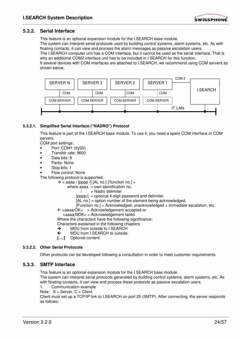
This feature is an optional expansion module for the I.SEARCH base module.
The system can interpret serial protocols used by building control systems, alarm systems, etc. As with
floating contacts, it can view and process the alarm messages as passive escalation users.
The I.SEARCH computer unit has a COM interface, but it cannot be used as the serial interface. That is
why an additional COM2 interface unit has to be included in I.SEARCH for this function.
If several devices with COM interfaces are attached to I.SEARCH, we recommend using COM servers as
shown below.
5.3.2.1. Simplified Serial Interface ("NADRO") Protocol
This feature is part of the I.SEARCH base module. To use it, you need a spare COM interface or COM
servers.
COM port settings:
• Port: COM1 (ttyS0)
• Transfer rate: 9600
• Data bits: 8
• Parity: None
• Stop bits: 1
• Flow control: None
The following protocol is supported: < aaaa / [pppp /] [AL no.] [/function no.] > where aaaa = own identification no. / = Nadro delimiter [pppp/] = optional 4-digit password and delimiter [AL no.] = option number of the element being acknowledged. [Function no.] = Acknowledged, unacknowledged = immediate escalation, etc. <aaaa/OK> = Acknowledgement accepted or <aaaa/NOK> = Acknowledgement failed Where the characters have the following significance: Characters explained in the following chapters: MDU from outside to I.SEARCH MDU from I.SEARCH to outside. [….] Optional content
5.3.2.2. Other Serial Protocols
Other protocols can be developed following a consultation in order to meet customer requirements.
5.3.3. SMTP Interface
This feature is an optional expansion module for the I.SEARCH base module.
The system can interpret serial protocols generated by building control systems, alarm systems, etc. As
with floating contacts, it can view and process these protocols as passive escalation users.
1. Communication example
Note: S = Server, C = Client
Client must set up a TCP/IP link to I.SEARCH on port 25 (SMTP). After connecting, the server responds
as follows:
COM COM COM COM
COM 2
IT LAN
SERVER N
COM SERVER
SERVER 3
COM SERVER
SERVER 2
COM SERVER
SERVER 1
I.SEARCH
COM SERVER

I.SEARCH System Description
Version 3.2.0 25/57
S: 220 I.SEARCH PageMail SMTP Service version 0.0.5 is ready
C: hello I.SEARCH
S: 250 Hello... nice to meet you
C: mail from: USER1
S: 250 OK
C: rcpt to: USER2
S: 250 OK
C: data
S: 354 Enter Mail, end by a line with only '.'
C: Test message from USER1 to USER2
C: .
S: 250 Message received OK
C: quit
S: 221 Goodbye! Have a nice day!
The server's responses always end with <CR><LF> (Carriage return, line feed). In the other direction, the
server will only interpret the client's commends if they end with at least one <LF>.
5.3.3.1. Sample Communication: SMTP over RS232
Note: S = Server, C = Client
Client must be connected to the server's serial port with a null-modem cable.
COM port settings:
• Port: COM1 (ttyS0)
• Transfer rate: 9600
• Data bits: 8
• Parity: None
• Stop bits: 1
• Flow control: None
The difference between this arrangement and SMTP over Ethernet is that the client has to make the first
step; the server does not respond automatically. So a message sent over RS232 might look something
like this: C: hello I.SEARCH
S: 250 Hello... nice to meet you
C: mail from: USER1
S: 250 OK
C: rcpt to: USER2
S: 250 OK
C: data
S: 354 Enter Mail, end by a line with only '.'
C: Test message from USER1 to USER2
C: .
S: 250 Message received OK
C: quit
S: 221 Goodbye! Have a nice day!
The server's responses always end with <CR><LF> (Carriage return, line feed). In the other direction, the
server will only interpret the client's commends if they end with at least one <LF> or one <CR>.
5.3.4. Server Monitoring
This feature is part of the I.SEARCH base module.
I.SEARCH has a simple server monitoring feature much like the DOS ping command. After a preset
number of pings have failed, a predefined message text is sent to a passive individual or group user.
5.3.5. MIP11 Plus
This function is a optional extention of the I.SEARCH base module and available from Version 2.1.7.14 or
higher.
MIP11 Plus implements the MIP11 Plus protocol. Serial and LAN interface via TCP Port 6618 is
supported.
I.SEARCH System Description
Version 3.2.0 26/57
The MIP11 protocol defines the character "[" as message terminator for alphanumeric messages and
therefore can not be used within a message, otherwise the message is invalid.
The "MIP11 Plus Extended" protocol uses the character "»" as message terminator. the character "»" is
not part of POCSAG character set.
To encrypt and transmit a MIP11 Plus message, a user with IDEA configuration with the according
RIC/sub address must be defined in I.SEARCH.
5.4. SNMP-Traps
This function is a optional extension of the I.SEARCH base module and available from Version 2.1.9 or
higher.
With this module I.SEARCH is capable or trapping "SNMP-Traps".
Each trapped " SNMP-Trap" leaves a record in logbook of the module and is being forwarded to the
"Input Handler" module.
The module has no configuration dialog, but can be controlled "Input Handler" module. Undesirable
"Traps" can be filtered by the "Input Handler" module.
5.5. E-Mail Messaging
This feature is part of the I.SEARCH base module.
Every passive user can have a mailbox address defined through a page mail name in the I.SEARCH mail
server.
The system can receive, process and interpret SMTP messages addressed to the page mail name. As
with floating contacts, it can view and process these messages as escalation passive users.
The e-mails may be part of regular office communications, or they may be alarm notifications generated
by building control systems, alarms, etc.
If necessary, a copy of the received e-mails can be forwarded to another preset mailbox address on an
outside mail server.
I.SEARCH System Description
Version 3.2.0 27/57
6. Processing Modules
6.1. User Groups
This function is part of the I.SEARCH base module.
There are two different types of users.
6.1.1. Active Users
As described in the "User permissions" chapter in this document, active users are people authorized to
log into the I.SEARCH system from an office PC within the customer premises (intranet) using a browser.
They are given a user name and password that they can manage (change) directly. The functions they
are entitled to use depend on which of the 8 possible authorization classes they are assigned to.
6.1.2. Passive User
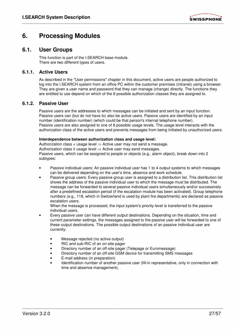
Passive users are the addresses to which messages can be initiated and sent by an input function.
Passive users can (but do not have to) also be active users. Passive users are identified by an input
number (identification number) (which could be that person's internal telephone number).
Passive users are also assigned to one of 8 possible usage levels. The usage level interacts with the
authorization class of the active users and prevents messages from being initiated by unauthorized users.
Interdependence between authorization class and usage level:
Authorization class < usage level ⇒ Active user may not send a message.
Authorization class ≥ usage level ⇒ Active user may send messages.
Passive users, which can be assigned to people or objects (e.g., alarm object), break down into 2
subtypes:
• Passive individual users: An passive individual user has 1 to 4 output systems to which messages
can be delivered depending on the user's time, absence and work schedule.
• Passive group users: Every passive group user is assigned to a distribution list. This distribution list
shows the address of the passive individual user to which the message must be distributed. The
message can be forwarded to several passive individual users simultaneously and/or successively
after a predefined escalation period (if the escalation module has been activated). Group telephone
numbers (e.g., 118, which in Switzerland is used by plant fire departments) are declared as passive
escalation users.
When the message is processed, the input system's priority level is transferred to the passive
individual users.
• Every passive user can have different output destinations. Depending on the situation, time and
current parameter settings, the messages assigned to the passive user will be forwarded to one of
these output destinations. The possible output destinations of an passive individual user are
currently:
• Message rejected (no active output)
• RIC and sub-RIC of an on-site pager
• Directory number of an off-site pager (Telepage or Euromessage)
• Directory number of an off-site GSM device for transmitting SMS messages
• E-mail address (in preparation)
• Identification number of another passive user (fill-in representative, only in connection with
time and absence management).
I.SEARCH System Description
Version 3.2.0 28/57
6.2. Processing Input Messages
No matter which input system originates a given message, it is always processed and forwarded to the
output systems according to the same method:
6.2.1. Messages to Passive Individual Users
This feature is part of the I.SEARCH base module.
All I.SEARCH messages are sent as text messages. That means that all the RIC sub-addresses of on-site pagers must be programmed with the alphanumeric calling class.
Sent messages to passive users with pagers can be of the following calling types:
Individual call:
A message is sent to only one receiver in the entire pager population. This on-site pager is the only one
who may receive, save and signal the message.
The RIC address of an individual call is assigned to individual users in I.SEARCH.
Broadcast call:
Several recipients with the same address code (RIC) are simultaneously called with one group
directory number. This type of call is preferable whenever messages need to be received quickly by a
large number of users (e.g., fire department alarm).
In this case, the broadcast call group must be defined as an individual user in I.SEARCH.
6.2.2. Messages to Passive Group Users
This feature is part of the I.SEARCH base module.
All I.SEARCH messages are sent as text messages. That means that all the RIC sub-addresses of on-site pagers must be programmed with the alphanumeric calling class.
The messages to passive group users are "duplicated" und individually sent to each passive individual
user listed in the group list. In terms of paging terminology, these messages belong to the "hunt group"
call type.
Hunt group:
Several (up to 32) receivers with different individual call address codes (RIC) are activated in
I.SEARCH when a message is sent to a user group. The input message is broadcast sequentially to the
number of individual users defined in the user group configuration (User administration, User group,
User selection). The RIC's used for the individual call are used for the individual users.
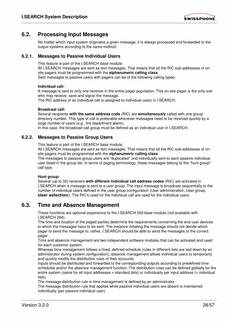
6.3. Time and Absence Management
These functions are optional expansions to the I.SEARCH 500 base module (not available with
I.SEARCH 200).
The time and location of the paged parties determine the requirements concerning the end user devices
to which the messages have to be sent. The instance initiating the message should not decide which
pager to send the message to; rather, I.SEARCH should be able to send the messages to the correct
pager.
Time and absence management are two independent software modules that can be activated and used
for each customer system.
Whereas time management follows a fixed, defined schedule (rules in different lists are laid down by an
administrator during system configuration), absence management allows individual users to temporarily
and quickly modify the distribution rules of their accounts.
Inputs should be distributed and forwarded to the corresponding outputs according to predefined time
schedules and/or the absence management function: The distribution rules can be defined globally for the
entire system (same for all input addresses = standard lists) or individually per input address (= individual
lists).
The message distribution rule in time management is defined by an administrator.
The message distribution rule that applies while passive individual users are absent is maintained
individually (per passive individual user).
I.SEARCH System Description
Version 3.2.0 29/57
Every active user with an authorization class > 0 who is also an passive individual user is authorized to
change the distribution criteria settings of his account with the absence wizard (in the browser). Active
users with an authorization class > 4 are authorized to change the distribution criteria of other passive
individual users with the absence wizard.
Absence messages can be entered (activated or deactivated) via the following interfaces:
• (In preparation) Absence management URL from PC (intranet browser)
• (In preparation) Pager deposit holder: Determines whether pager is deposited or not.
• (In preparation) Telephone service feature: By selecting a PBX process, etc.
• (In preparation) Time recording system: Interpreting data from a time recording system.
• (In preparation) Switchboard: Interpreting the state of a switchboard's push buttons.
• (In preparation) Outlook absence feature: Importing the data from the absence wizard of common
calendar programs like Microsoft Outlook, PDA's etc.
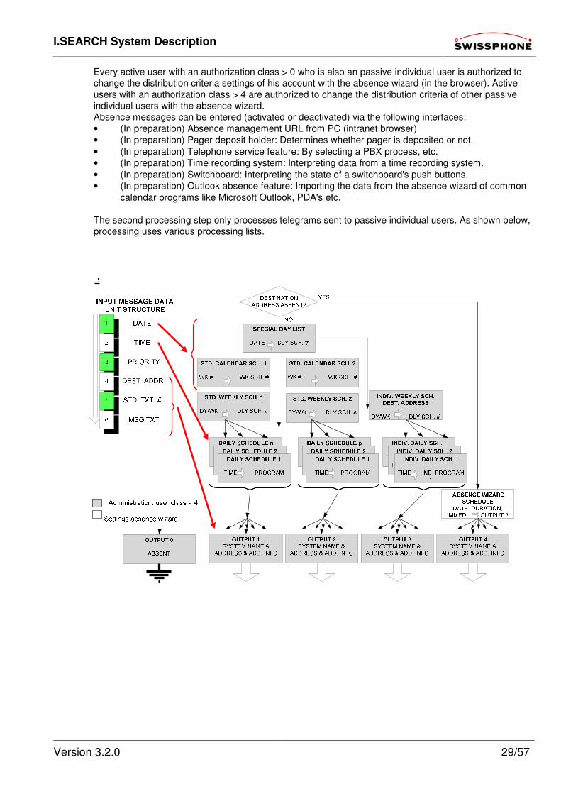
The second processing step only processes telegrams sent to passive individual users. As shown below,
processing uses various processing lists.
I.SEARCH System Description
Version 3.2.0 30/57
Input telegram structure:
The telegrams being processed must always have the same format regardless of their origin (e.g., ESPA
4.4.3, direct messaging, or alarm contact).
Telegrams consist of:
Date, time, priority of message (determined by input system), number of the passive user, fix text number
and original message text.
The original message text field is optional, all others are mandatory.
Assigning time scheduling lists to passive users:
Every passive user is assigned to one of the following possible time schedules:
• Calendar schedule 1
• Calendar schedule 2
• Standard weekly schedule 1
• Standard weekly schedule 2
• Individual weekly schedule
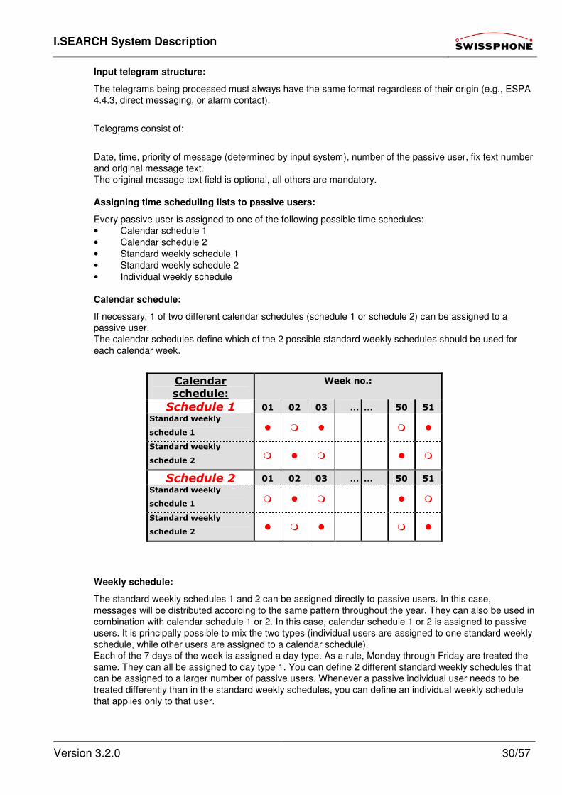
Calendar schedule:
If necessary, 1 of two different calendar schedules (schedule 1 or schedule 2) can be assigned to a
passive user.
The calendar schedules define which of the 2 possible standard weekly schedules should be used for
each calendar week.
Calendar
schedule:
Week no.:
Schedule 1 01 02 03 … ... 50 51
Standard weekly
schedule 1
Standard weekly
schedule 2
Schedule 2 01 02 03 … ... 50 51
Standard weekly
schedule 1
Standard weekly
schedule 2
Weekly schedule:
The standard weekly schedules 1 and 2 can be assigned directly to passive users. In this case,
messages will be distributed according to the same pattern throughout the year. They can also be used in
combination with calendar schedule 1 or 2. In this case, calendar schedule 1 or 2 is assigned to passive
users. It is principally possible to mix the two types (individual users are assigned to one standard weekly
schedule, while other users are assigned to a calendar schedule).
Each of the 7 days of the week is assigned a day type. As a rule, Monday through Friday are treated the
same. They can all be assigned to day type 1. You can define 2 different standard weekly schedules that
can be assigned to a larger number of passive users. Whenever a passive individual user needs to be
treated differently than in the standard weekly schedules, you can define an individual weekly schedule
that applies only to that user.
I.SEARCH System Description
Version 3.2.0 31/57
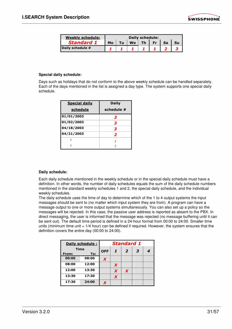
Weekly schedule: Daily schedule:
Standard 1 Mo Tu We Th Fr Sa Su
Daily schedule # 1 1 1 1 1 2 3
Special daily schedule:
Days such as holidays that do not conform to the above weekly schedule can be handled separately.
Each of the days mentioned in the list is assigned a day type. The system supports one special daily
schedule.
Special daily
schedule
Daily
schedule #
01/01/2003 3
01/02/2003 3
04/18/2003 3
04/21/2003 2
:
:
:
:
Daily schedule:
Each daily schedule mentioned in the weekly schedule or in the special daily schedule must have a
definition. In other words, the number of daily schedules equals the sum of the daily schedule numbers
mentioned in the standard weekly schedules 1 and 2, the special daily schedule, and the individual
weekly schedules.
The daily schedule uses the time of day to determine which of the 1 to 4 output systems the input
messages should be sent to (no matter which input system they are from). A program can have a
message output to one or more output systems simultaneously. You can also set up a policy so the
messages will be rejected. In this case, the passive user address is reported as absent to the PBX. In
direct messaging, the user is informed that the message was rejected (no message buffering until it can
be sent out). The default time period is defined in a 24-hour format from 00:00 to 24:00. Smaller time
units (minimum time unit = 1/4 hour) can be defined if required. However, the system ensures that the
definition covers the entire day (00:00 to 24:00).
Daily schedule : Standard 1
Time
From: To: OFF 1 2 3 4
00:00 08:00 X
08:00 12:00 X
12:00 13:30 X X
13:30 17:30 X
17:30 24:00 X
I.SEARCH System Description
Version 3.2.0 32/57
Absence wizard schedule:
Both the user and active users with an authorization class > 3 can override the time schedules described
above with the absence wizard of a passive user address.
With the absence wizard, you can
• Program or pre-program routings to another passive individual user. Once routed, the messages
follow the distribution rules of the new passive individual user. Chain routes (routes of routes) must
be prevented (automatic check when the route is programmed or pre-programmed).
• Temporarily distribute the messages in a way that differs from programs 1 to 4 of the output
schedule
• Manage distribution variations due to holiday, all-day, temporary or regular absences
• Leave messages for direct messaging users
6.4. Escalation Management (on request)
6.4.1. Escalation
(In preparation) This function is an optional expansion to the I.SEARCH 500 base module (not available
with I.SEARCH 200). If the user is an passive escalation user, the system accesses the escalation list first. Every passive
escalation user is assigned one of 2 possible default escalation lists (default 1 to default 2) or an
escalation list individually designed for this user.
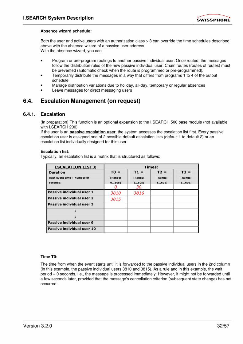
Escalation list:
Typically, an escalation list is a matrix that is structured as follows:
ESCALATION LIST X Times:
T0 =
[Range:
0...60s]
T1 =
[Range:
1...60s]
T2 =
[Range:
1...60s]
T3 =
[Range:
1...60s]
Duration
[last event time + number of
seconds]
0 30 Passive individual user 1 3810 3816 Passive individual user 2 3815 Passive individual user 3
: :
Passive individual user 9 Passive individual user 10
Time T0:
The time from when the event starts until it is forwarded to the passive individual users in the 2nd column
(in this example, the passive individual users 3810 and 3815). As a rule and in this example, the wait
period = 0 seconds, i.e., the message is processed immediately. However, it might not be forwarded until
a few seconds later, provided that the message's cancellation criterion (subsequent state change) has not
occurred.
I.SEARCH System Description
Version 3.2.0 33/57
Time T1:
The time from T0 until the event is forwarded to the passive individual users in the 3rd column, provided
that the message's cancellation criterion (subsequent state change) has not occurred. In the example,
this wait time is set to 30 seconds.
Time T2:
The time from T1 until the event is forwarded to the passive individual users in the 4th column, provided
that the message's cancellation criterion (subsequent state change) has not occurred. There is no further
escalation after T1 in the example.
Time T3:
The time from T2 until the event is forwarded to the passive individual users in the 5th column, provided
that the message's cancellation criterion (subsequent state change) has not occurred. There is no further
escalation after T1 in the example.
Passive individual users 1, 2, 3 ... 32:
Each column states which passive users the message should be simultaneously forwarded to. Messages
sent to passive individual users are processed according to the current time and absence settings of their
passive users.
In the example, the original message is immediately forwarded to the passive individual users 3810 and
3815 at the start of the event. If the state of the passive escalation users does not change within the next
30 seconds, the original message will additionally be sent to the passive individual user 3816. Caution: Distribution lists with a large number of passive individual users may temporarily overload the
output system. This leads to major delays and lost messages. If you want a message to be sent to more
than 23 passive users, you should do this by some other means if at all possible.
Recommended solutions:
• Using a group RIC or a group directory number if the output is to be sent to output systems with
pagers. In this case, the identification number of the applicable object corresponds to a passive
individual user instead of a passive escalation user.
• Using the DynGo® principle, if the message is to be forwarded to an output systems with POCSAG
pagers. In this case, the identification number of the applicable object corresponds to a passive
individual user instead of a passive escalation user. The DynGo® alarm part "(100)" is added to the
message standard text.
• If messages are desired to be forwarded to several SMS receivers, the use of a SMS Large
Account is recommended.
An escalation list consists of at least one passive individual user at the time of T0.
If (at Tx) the message(s) cannot be sent to an escalation level for technical or absence reasons and
another escalation level Tx+1 is specified in the escalation list, the system escalates to the next level
immediately without waiting for the defined timer value to pass.
In its simplest initial manifestation, an escalation list consists of only one column with the time T0 (T0
value = 0). This escalation list is termed the group list. In the case of a passive individual user, the received MDU is immediately forwarded to the second
processing stage.

I.SEARCH System Description
Version 3.2.0 34/57
6.4.2. Acknowledgement process
Characters explained in the following chapters:
MDU from outside to I.SEARCH
MDU from I.SEARCH to outside. [….] Optional content
Purpose
The purpose of the acknowledgement process is to stop the escalation.
The following acknowledgement processes (cumulative and optional) can be used:
Independent:
Return the element to its original state (only possible for I/O messages)
Floating (I/O) contact:
(From I/O module) Change the state of another I/O contact assigned to this alarm element.
DTMF: 2-way input:
Dial main (PBX) phone number
DTMF 5 + frequency "OK" = Suffix dialling ready
DTMF dialling: aaaa ∗ [pppp ∗] [AL no] [*function no] #
where aaaa = Own identification no.
∗ = DTMF separator
[pppp∗] = Optional 4-digit password and separator
[AL no.] = Optional number of the element being acknowledged.
[Function no.] = Acknowledged, unacknowledged = immediate escalation, etc.
DTMF 1 + frequency "OK" = Acknowledgement accepted or
DTMF 2 + frequency "NOK" = Acknowledgement failed
SMTP interface:
Destination aaaa@ I.SEARCH
Originator [email protected]
Subject < aaaa / [pppp /] [AL no] [/function no] >
and/or
Text < aaaa / [pppp /] [AL no] [/function no]>
where aaaa = own identification no.
/ = Nadro separator
[pppp/] = Optional 4-digit password and separator
[AL no.] = Optional number of the element being acknowledged.
[Function no.] = Acknowledged, unacknowledged = immediate escalation, etc.
Destination [email protected]
Originator [email protected]
Subject <aaaa/OK> = Acknowledgement accepted or
Text <aaaa/OK> = Acknowledgement accepted or
Subject <aaaa/NOK> = Acknowledgement failed or
Text <aaaa/NOK> = Acknowledgement failed
Simplified serial interface ("NADRO") protocol:
< aaaa / [pppp /] [AL no.] [/function no.] >
where aaaa = Own identification no.
/ = Nadro separator
[pppp/] = Optional 4-digit password and separator
[AL no.] = Optional number of the element being acknowledged.
[Function no.] = Acknowledged, unacknowledged = immediate escalation, etc.
<aaaa/OK> = Acknowledgement accepted or
<aaaa/NOK> = Acknowledgement failed
I.SEARCH System Description
Version 3.2.0 35/57
Browser acknowledgement:
Users can manage a log book-like list, e.g.:
Unacknowledged elements (last in uppermost line):
AL no x Name State Eventdate+time
AL no y Name State Eventdate+time
AL no z Name State Eventdate+time
Acknowledged elements (last in uppermost line):
AL no a Name State Eventdate+time Qdate+time+ident.#
AL no b Name State Eventdate+time Qdate+time+ident.#
AL no b Name State Eventdate+time Qdate+time+ident.#
where = Unacknowledged element. Acknowledgement
permitted for user.
= Unacknowledged element. Acknowledgement
not permitted for user.
= Acknowledged element (limited to a specific
number, e.g., logs)
6.5. System Utilities
6.5.1. System Configuration
This feature is part of the I.SEARCH base module.
Generally, the I.SEARCH system administrator is one of the customer's employees.
The system administrator logs onto to system by pointing his (intranet) browser to the I.SEARCH
homepage URL and entering his user name and password. This gives him access to the following
function URL:
System administration:
• General system configuration (including specifying the user language or the browser start pages
when users log on)
• Configuration of the I/O contact texts and destinations
• Definition of list output formats (field name and position)
• Configuration of optional additional, search and CSV export file fields
• Backup and restore operations (see chapter Backup and Restore Operations)
• Log book access incl. export as ASCII files (see chapter Log File Export Operations)
• Access to system utilities
6.5.2. User Administration
This feature is part of the I.SEARCH base module.
Generally, the I.SEARCH system administrator is one of the customer's employees.
The system administrator logs onto to system by pointing his (intranet) browser to the I.SEARCH
homepage URL and entering his user name and password. This gives him access to the following
function URL:
User administration:
• Add new user
• Change user data
• Delete user accounts
• Reset passwords
Passive user administration:
• Add new passive user
• Start adding new passive users with CSV file (see next chapter)
• Change passive users
• Delete passive user accounts
I.SEARCH System Description
Version 3.2.0 36/57
• Administer (add, change, delete) text libraries
• Administer (add, change, delete) daily schedules, time schedules
• Administer (add, change, delete) distribution lists
• Administer (add, change, delete) passive user output addresses
6.5.3. User Administration with CSV Files
This feature is part of the I.SEARCH base module.
The administrator can use the CSV file import function to set up a large number of users. It allows him to
add all the user accounts in a file to the I.SEARCH system with only one read operation. A CSV file is a file with the name xxxxx.CSV.
It consists of a header defined by Swissphone followed by an unspecified number of rows. Each row
contains the account data of an I.SEARCH user account.
The different parameter values of a user account are separated in the row with prescribed delimiters
(semicolons [= ";"]). The order and meaning of the individual parameters in the rows are specified by
Swissphone AG.
This process can be used to sort and complete the data as required to use I.SEARCH. This data may
also come from another system, such as a PBX.
Possible operations when importing data in a CSV file. I.SEARCH CSV file I.SEARCH Database content Row Database content before import Database content after import
Account does not exist New account data Account added Account already exists Existing account data Account data overwritten (except password) If required (as per input in "IMPORT CSV FILE" input screen): Account already exists Account not included Account data will be deleted
CSV files can best be edited and created with the common Microsoft EXCEL program. Swissphone AG
provides its customers with an EXCEL template called "CSV template I.SEARCH Vx.x" to help
administrators generate the user data in an EXCEL file.
The operations that have changed the I.SEARCH database during the CSV file import are logged in a
journal and displayed in an acknowledgement window.
The administrator can export all the user data set up in the system. The export is done in the form of a
CSV file that in turn can be input into an EXCEL file, for example.
The following options are available for both user data and group data:
• Header + column name + data: The exported CSV file resembles the EXCEL import file template in
terms of structure.
• Column name + data: The exported CSV file does not include a header section. The first three
rows in the EXCEL file template are omitted. The only output is the column header and the actual
user data.
• Data only: The exported CSV file includes neither a header section nor a column name. The first
four rows of the EXCEL file template are omitted. The only output is the user data.
•
Two different CSV files (user data and group data) are created. The system tells the administrator that the
two files have been successfully created.
The files can be stored anywhere on a server or PC.
6.5.4. Using Additional Fields
This feature is part of the I.SEARCH base module.
User accounts have defined parameters that specify a user (database set). In addition to the fields
predefined by the I.SEARCH system, there are ten more fields that can be freely defined. These fields
can serve two different purposes:
I.SEARCH System Description
Version 3.2.0 37/57
• They can be displayed and used in the user selection lists for "SEND MESSAGE" (direct
messaging). This should help the active user to locate certain users in a large list faster (e.g., using
internal organizational labels for the passive user).
• They can be displayed and used in the user selection lists for "ADMINISTER USER" and
"ADMINISTER GROUP". This should help the administrator to locate certain users in a large list
faster (e.g., with office numbers).
• These fields can be appended to any LOG entry in the CSV export files. With this information,
these log files can, for example, be used for internal accounting for initiated calls, or for statistical
analyses. (See chapter Log File Export Operations)
6.5.5. Operational Analysis and Error Management
This feature is part of the I.SEARCH base module.
The I.SEARCH system administrator has various tools for on-site error analysis:
• Logs of completed transactions
• Per input system
• Per output system
• Per data manipulation
• Start diagnosis processes
• Visual and audible system alarm output with acknowledgement option
6.5.6. Backup and Restore Operations
This feature is part of the I.SEARCH base module.
The backup function enables you to save all software programs, system configurations, system settings
and user configuration data in a file. So, in case of a system failure or data loss, this data can be restored
to the system, making it fit for operation based on the restored data and programs.
The backup function can be initiated by the administrator manually at any time.
In addition, the backup function can also be initiated automatically at a predefined time (once a day,
weekly, monthly).
In addition to the local I.SEARCH server, the backup can also be saved to an external server or PC,
which adds to the security of the system. In case of a more serious system failure (e.g., in case of fire or
flooding), a new system can quickly be put into operation with the most recent state of the destroyed
system provided that the backup file was saved on a server not affected by the damage.
The following information must be predefined for exporting the backup file to a third-party server in
I.SEARCH:
• Name of the server to which the backup file must be loaded
• Name of the directory in which the backup file should be saved
• Windows account information allowing the I.SEARCH system to log onto the server or PC to save
the data, including work group information: account, login name and login password.
The restore function can be initiated by the administrator manually at any time.
6.5.7. Log File Export Operations
This feature is part of the I.SEARCH base module.
The requested log files (one file per input system, per output system and per data manipulation) can be
exported regularly to an external server or PC in a similar fashion as the backup. These exports are
initiated automatically at the same time as the backup (identical time information). The information
required for the export has the same significance as the backup definitions described above.
Exporting the log files may become necessary for various reasons:
• As a backup: To prove when a message was sent out at a later time.
• As a basis for internal accounting: The log files can serve as raw data for the internal accounting
of the sent calls. Each log file entry can be supplemented with specific, additional optional fields
defined by the administrator. One example is the users' cost centre number. The log CSV export
file can be imported into Microsoft EXCEL and simply converted into a list for internal accounting.
I.SEARCH System Description
Version 3.2.0 38/57
• As a basis for internal statistics: The log files can serve as raw data for statistically evaluating
sent calls, system usage etc. As in internal accounting, each log file entry can be supplemented
with specific, additional optional fields defined by the administrator. The log CSV export file can be
imported into Microsoft EXCEL and simply converted into a list for internal accounting.
6.5.8. Remote Access
This function is an optional expansion to the I.SEARCH 500 base module (e.g., in combination with a
service level agreement; not available with I.SEARCH 200).
Access from ISDN base terminal or PSTN analogue modem. The connection is established in a call-back
procedure, i.e., the service and support agent establishes a modem connection between his workstation
PC and the I.SEARCH system. I.SEARCH identifies the calling workstation and by the user name and
terminates the modem connection. The I.SEARCH system subsequently establishes a modem
connection to a call-back number using the same ISDN or analogue telephony network. A remote data
transmission connection is established when the service and support agent accepts this call back at his
workstation PC. Via this remote data transmission connection, the service and support agent can then log
onto the remote I.SEARCH in his browser. He can fully use the same browser functionalities of the
system as if he were using the system on the intranet.
A wide range of operational analysis and error management tools are available. The operational data and
logs can be used to determine the causes of problems or irregularities.
6.6. High Availability Cluster
With the "High Availability Cluster" module two I.SEARCH can be connected by LAN and will act like one
System. This function is available from Version 2.1.9.
If one I.SEARCH is not available or not functioning, the second I.SEARCH will overtake the job, so that
there is always a working functioning System available
Each I.SEARCH has its own IP adress which allows access to the single I.SEARCH system and a third
virtual IP address which is shared by both I.SEARCH systems.
The external systems which communicate with the I.SEARCH system, always use the virtual IP-Address.
The I.SEARCH owning the virtual IP-Address is the active system, the other is the "standby" system. As
soon as the active system fails the "standby" system takes over.
I.SEARCH System Description
Version 3.2.0 39/57
7. Output Modules
7.1. General Information
I.SEARCH supports many different output systems.
They include on-site POCSAG network, traditional paging system, DECT messaging, off-site paging
network (TELEPAGE, Euromessage), GSM-SMS. Other output systems can be added at any time as
required.
Different output systems are connected to meet different customer needs. Every passive user of an
I.SEARCH system is assigned between 1 and 4 output systems. The number and type of output systems
vary from passive user to passive user.
From the intranet browser GUI, the administrator (user class > 3) defines the output systems that passive
users can use along with their addresses and additional information (directory number and legitimation
code for a paging output system).
Received messages are distributed in accordance with the time and absence management settings.
A message received from an input system can be simultaneously output to up to 4 different output system
addresses for a passive user at a certain point in time.
The messages may also be distributed to various output system addresses, depending on the day of the
week and the time.
Special aspects of on-site POCSAG output systems:
POCSAG receivers for on-site output systems should be able to determine the priority level of a received
message and issue a special bleep for each priority level.
You can only configure these different bleeps with a POCSAG protocol and a standard pager if you send
each priority level to a different RIC sub address. To simplify the programming of the entire pager
population refer to the following table.
Priority level 0 (lowest priority): RIC sub address A for all RIC's
Priority level 1: RIC sub address B for all RIC's
Priority level 2: RIC sub address C for all RIC's
Priority level 3 (highest priority): RIC sub address D for all RIC's
The frequentness with which messages are sent (repeated) depends on the priority level. The number of
times a message is sent and the minimum wait period between these times is parameterized for each
priority level and customer system.
Thus, the address for each on-site POCSAG pager is simply defined as the RIC value.
The system is not designed to support bleep differentiation for different priority levels on off-site output
systems.
7.2. On-Site Paging
The I.SEARCH system can also control a local POCSAG paging network.
Unlike local paging networks operated by conventional paging systems, I.SEARCH does not use
proprietary transmission protocols. Instead, it uses the international paging standard POCSAG (Post
Office Code Standardisation Advisory Group, a.k.a. CCIR Radiopaging Code No. 1).
The paging frequency for the premises-based paging network is assigned to the customer by a national
frequency regulator (such as BAKOM in Switzerland).
Acting on behalf of the customer, Swissphone files the license application with the regulator for the
required frequency. Then, it builds a local paging network to offer coverage throughout the company
premises. The network contains 1 to n local paging transmitters.
The messages input in I.SEARCH are transmitted by the local transmitter(s).
A Radio Identification Code (RIC) is transmitted with the message to address the destination pager(s).
If the transmitted RIC address matches one of the addresses programmed in the pager (a pager can
have several different RIC's), the pager will beep and display the message.
In this document, the term "on-site pager" refers to a pager that receives the assigned local POCSAG
frequency and interprets the POCSAG code words.

I.SEARCH System Description
Version 3.2.0 40/57
On-site pagers should be able to determine the priority level of a received message and issue a special
bleep for each priority level.
You can only configure these different beeps with a POCSAG pager if you send each priority level to one
of the 4 different RIC/sub addresses.
To make it easier to program the entire pager population for the system, all pagers (whether or not they
are supposed to receive all messages in all priority classes) have to be configured with the following
definition.
Priority level 0 (lowest priority): RIC sub address A for all RIC's
Priority level 1: RIC sub address B for all RIC's
Priority level 2: RIC sub address C for all RIC's
Priority level 3 (highest priority): RIC sub address D for all RIC's
The frequentness with which messages are sent (repeated) depends on the priority level. The number of
times a message is sent and the minimum wait period between these times is parameterized in each
I.SEARCH customer system ("System configuration", "General settings"). These parameters should be
considered when programming the on-site pagers.
7.2.1. Transmitters
I.SEARCH can only be equiped with one integrated POCSAG transmitter. To extend radio coverage it is
possible to operate I.SITE transmitters (refer to 7.2.1.2) or I.SEARCH Slave transmitters (refer to ) with
I.SEARCH.
In any case I.SEARCH must be equipped with the SC2000 module (synchronisation unit) in order to
format the POCSAG data and control the transmitters. The SC2000 module requires a 4TE bay in the 19"
rack.
7.2.1.1. Integrated 4W POCSAG Transmitter DS1178
This feature is an optional expansion module for the I.SEARCH base module
Transmitter
The transmitter Swissphone DS1178 is licensed for on-site paging according to ETSI 300224. The
transmitter is designed for digital data transmission. Modulation type is DFSK.
Transmitter characteristics
Refer to 3.10.1
Antenna system
Refer to 3.10.2
I-SEARCH
SC2000
0.1-4W
POCSAG
Trans-mitter
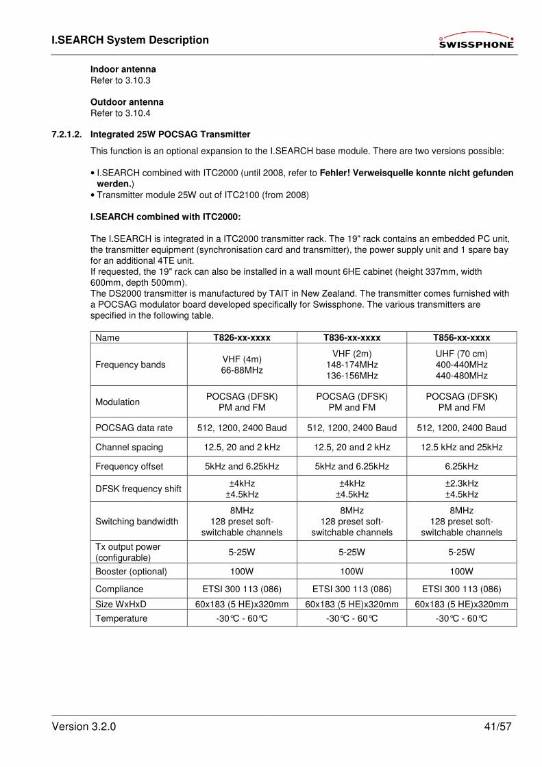
I.SEARCH System Description
Version 3.2.0 41/57
Indoor antenna
Refer to 3.10.3
Outdoor antenna
Refer to 3.10.4
7.2.1.2. Integrated 25W POCSAG Transmitter
This function is an optional expansion to the I.SEARCH base module. There are two versions possible:
• I.SEARCH combined with ITC2000 (until 2008, refer to Fehler! Verweisquelle konnte nicht gefunden
werden.)
• Transmitter module 25W out of ITC2100 (from 2008)
I.SEARCH combined with ITC2000:
The I.SEARCH is integrated in a ITC2000 transmitter rack. The 19" rack contains an embedded PC unit,
the transmitter equipment (synchronisation card and transmitter), the power supply unit and 1 spare bay
for an additional 4TE unit.
If requested, the 19" rack can also be installed in a wall mount 6HE cabinet (height 337mm, width
600mm, depth 500mm).
The DS2000 transmitter is manufactured by TAIT in New Zealand. The transmitter comes furnished with
a POCSAG modulator board developed specifically for Swissphone. The various transmitters are
specified in the following table.
Name T826-xx-xxxx T836-xx-xxxx T856-xx-xxxx
Frequency bands VHF (4m)
66-88MHz
VHF (2m)
148-174MHz
136-156MHz
UHF (70 cm)
400-440MHz
440-480MHz
Modulation POCSAG (DFSK)
PM and FM
POCSAG (DFSK)
PM and FM
POCSAG (DFSK)
PM and FM
POCSAG data rate 512, 1200, 2400 Baud 512, 1200, 2400 Baud 512, 1200, 2400 Baud
Channel spacing 12.5, 20 and 2 kHz 12.5, 20 and 2 kHz 12.5 kHz and 25kHz
Frequency offset 5kHz and 6.25kHz 5kHz and 6.25kHz 6.25kHz
DFSK frequency shift ±4kHz
±4.5kHz
±4kHz
±4.5kHz
±2.3kHz
±4.5kHz
Switching bandwidth
8MHz
128 preset soft-
switchable channels
8MHz
128 preset soft-
switchable channels
8MHz
128 preset soft-
switchable channels
Tx output power
(configurable) 5-25W 5-25W 5-25W
Booster (optional) 100W 100W 100W
Compliance ETSI 300 113 (086) ETSI 300 113 (086) ETSI 300 113 (086)
Size WxHxD 60x183 (5 HE)x320mm 60x183 (5 HE)x320mm 60x183 (5 HE)x320mm
Temperature -30°C - 60°C -30°C - 60°C -30°C - 60°C

I.SEARCH System Description
Version 3.2.0 42/57
Transmitter module 25W out of ITC2100:
The 25W transmitter module out of ITC2100 can be integrated in the I.SEARCH 19" rack (former I.SEARCH 500 refer to Fehler! Verweisquelle konnte nicht gefunden werden.).
7.2.1.3. I.SITE Transmitters
This function is an optional extension to the I.SEARCH base module.
I.SITE is used together with I.SEARCH. It is an FSK transmitter that receives the modulation data over a
serial interface. This serial interface can be a standard RS232 or a floating RS422 connection. I.SEARCH
also needs to have the SC2000 synchronisation unit and OC2000 RS232/RS422 interface to format the
data.
The remote I.SITE transmitters are connected to the main module over a serial RS422 interface. The
serial connection must be 2 x 2 wires for I.SITE light and 3 x 2 wires for I.SITE II (one additional wire pair
for acknowledge), preferably as twisted pairs in order to reduce interference as much as possible. The
maximum connection length is 1200m. In case of I.SITE light 10 transmitters can be attached to one
connection.
I.SITE
I.SITE
I.SITE
I.SEARCH
OC2000
RS4221
2
3
4
SC2000
M
RS
42
2
RS232
MI.SITE
RS422
RS232
I.SITE

I.SEARCH System Description
Version 3.2.0 43/57
Transmitter "I.SITE light"
Refer to 7.2.1.1 Transmitter
Transmitter "I.SITE II"
Refer to 7.2.1.2 Transmitter module 25W out of ITC2100
Transmitter properties
Refer to 3.10.1
Transmitter interface
The interface contains the functions, transmitter keying, data input and RX/TX lines. The input signal
levels are TTL. The feed voltage is 13.8V. The HF output connection is engineered as a BNC connection.
Note: The output must always be terminated with 50Ω. ESD hazard!
Interface module
The interface card converts the input signals to TTL levels for the transmitter. There is also a 5V voltage
regulator for the electronic components. A TTL-RS422 converter is available in case more transmitters
are installed later. Individual solder straps are used to fully configure the interface module.
Power supply
The operating voltage is provided by a primary clocked power generator (CPG). The primary CPG
generates the +13.8V output voltage. On the input side, it is fed with 230V/50 Hz.
Power cable
A case socket (C13 socket) is built in for standard power cables. That means the system can ship with a
country-specific power cable.
Protection systems (ESD)
The system power supply is connected to the power grid ground. The antenna uses a floating output.
Antenna system
Refer to 3.10.2
Indoor antenna
Refer to 3.10.3
Outdoor antenna
Refer to 3.10.4
Case/design/mechanics
The case was specifically chosen for indoor/outdoor installations. It meets IP 66 protection standards.
I.SITE light
I.SITE II
I.SEARCH System Description
Version 3.2.0 44/57
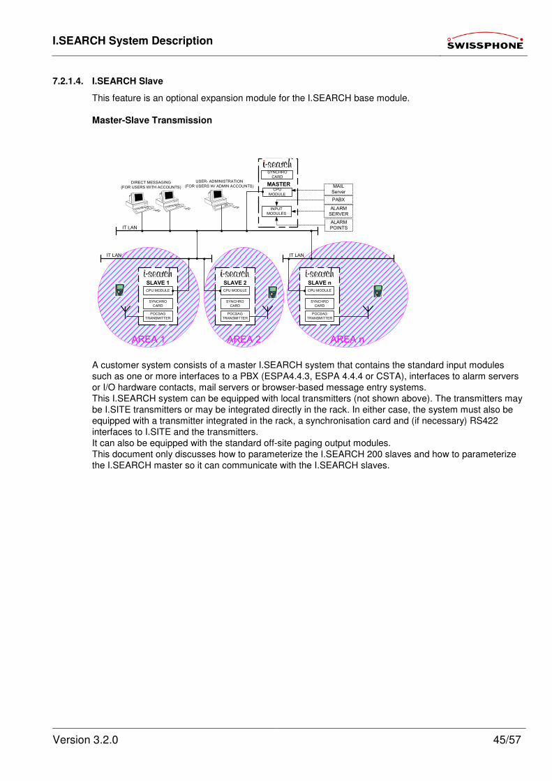
I.SEARCH System Description
Version 3.2.0 45/57
7.2.1.4. I.SEARCH Slave
This feature is an optional expansion module for the I.SEARCH base module.
Master-Slave Transmission
A customer system consists of a master I.SEARCH system that contains the standard input modules
such as one or more interfaces to a PBX (ESPA4.4.3, ESPA 4.4.4 or CSTA), interfaces to alarm servers
or I/O hardware contacts, mail servers or browser-based message entry systems.
This I.SEARCH system can be equipped with local transmitters (not shown above). The transmitters may
be I.SITE transmitters or may be integrated directly in the rack. In either case, the system must also be
equipped with a transmitter integrated in the rack, a synchronisation card and (if necessary) RS422
interfaces to I.SITE and the transmitters.
It can also be equipped with the standard off-site paging output modules.
This document only discusses how to parameterize the I.SEARCH 200 slaves and how to parameterize
the I.SEARCH master so it can communicate with the I.SEARCH slaves.
AREA 2 AREA nAREA 1
ALARM
SERVER
IT LAN
DIRECT MESSAGING
(FOR USERS WITH ACCOUNTS)
USER- ADMINISTRATION
(FOR USERS W/ ADMIN ACCOUNTS)
PABX
INPUT
MODULES
MASTER
ALARM
POINTS
SYNCHRO
CARD
SLAVE n
CPU
MODULE
CPU MODULE
POCSAG
TRANSMITTER
SYNCHRO
CARD
SLAVE 2
CPU MODULE
POCSAG
TRANSMITTER
SYNCHRO
CARD
SLAVE 1
CPU MODULE
POCSAG
TRANSMITTER
IT LAN IT LAN
Server
SYNCHRO
CARD
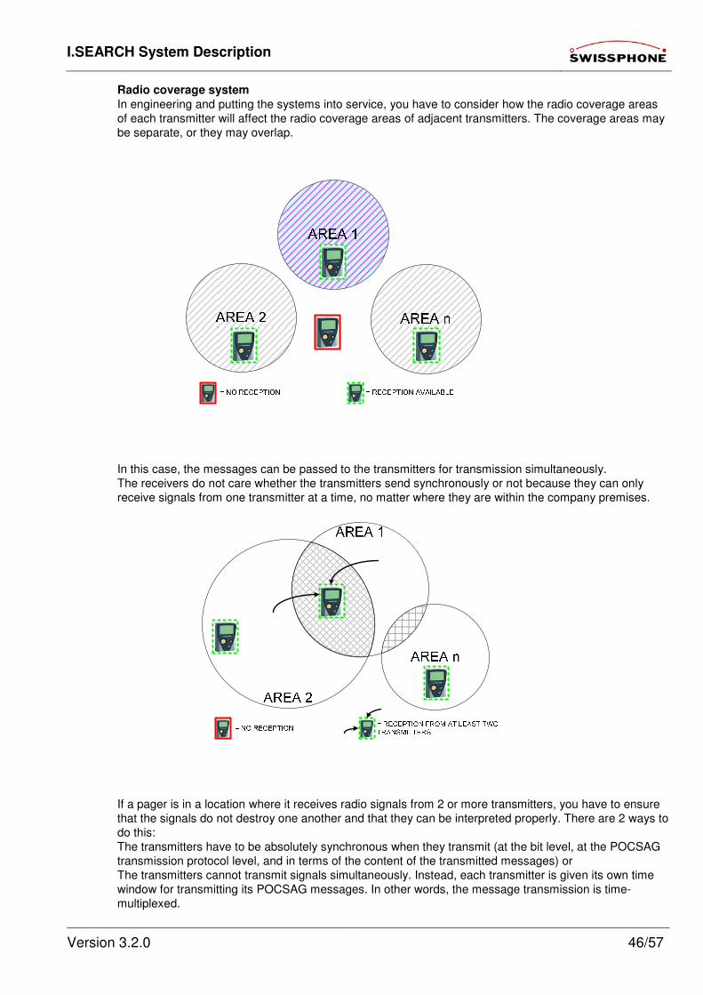
I.SEARCH System Description
Version 3.2.0 46/57
Radio coverage system
In engineering and putting the systems into service, you have to consider how the radio coverage areas
of each transmitter will affect the radio coverage areas of adjacent transmitters. The coverage areas may
be separate, or they may overlap.
In this case, the messages can be passed to the transmitters for transmission simultaneously.
The receivers do not care whether the transmitters send synchronously or not because they can only
receive signals from one transmitter at a time, no matter where they are within the company premises.
If a pager is in a location where it receives radio signals from 2 or more transmitters, you have to ensure
that the signals do not destroy one another and that they can be interpreted properly. There are 2 ways to
do this:
The transmitters have to be absolutely synchronous when they transmit (at the bit level, at the POCSAG
transmission protocol level, and in terms of the content of the transmitted messages) or
The transmitters cannot transmit signals simultaneously. Instead, each transmitter is given its own time
window for transmitting its POCSAG messages. In other words, the message transmission is time-
multiplexed.
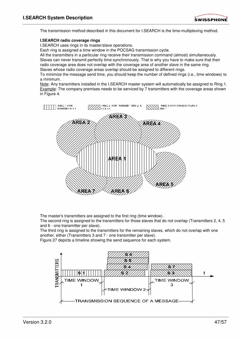
I.SEARCH System Description
Version 3.2.0 47/57
The transmission method described in this document for I.SEARCH is the time-multiplexing method.
I.SEARCH radio coverage rings
I.SEARCH uses rings in its master/slave operations.
Each ring is assigned a time window in the POCSAG transmission cycle.
All the transmitters in a particular ring receive their transmission command (almost) simultaneously.
Slaves can never transmit perfectly time-synchronously. That is why you have to make sure that their
radio coverage area does not overlap with the coverage area of another slave in the same ring.
Slaves whose radio coverage areas overlap should be assigned to different rings.
To minimize the message send time, you should keep the number of defined rings (i.e., time windows) to
a minimum.
Note: Any transmitters installed in the I.SEARCH master system will automatically be assigned to Ring 1.
Example: The company premises needs to be serviced by 7 transmitters with the coverage areas shown
in Figure 4.
The master's transmitters are assigned to the first ring (time window).
The second ring is assigned to the transmitters for those slaves that do not overlap (Transmitters 2, 4, 5
and 6 - one transmitter per slave).
The third ring is assigned to the transmitters for the remaining slaves, which do not overlap with one
another, either (Transmitters 3 and 7 - one transmitter per slave).
Figure 27 depicts a timeline showing the send sequence for each system.
I.SEARCH System Description
Version 3.2.0 48/57
Transmitters assigned to the same ring (here, Transmitters 2, 4, 5 and 6; or 3 and 7) are addressed by
the master in a sequence preset during the configuration.
The master controls all the transmissions. Once it finishes its own transmission (Ring 1), it sends the
message over the LAN to the next I.SEARCH slave on the ring. If there is no such slave, the message will
be sent to the first slave in the next ring (Ring 2). This I.SEARCH slave acknowledges the receipt of the
transmission command and its readiness to transmit the message. This method continues until all the
slaves in the same ring have been addressed. Once the last designated slave in the ring has been
addressed, the slave tells the master when it is done transmitting. That way, the master knows that this
ring is finished with its transmissions and it can address the next ring.
The process continues until all I.SEARCH slaves have transmitted the message.
The messages are transmitted in the order specified in the slave server list. This list is stored in the
I.SEARCH master (see the "Master/slave configuration" chapter).
7.3. IDEA Encryption
This module is a optional extension module of the I.SEARCH base module and available from Version 2.1.7.14. With IDEA encryption messages can be encrypted and sent to encryption capable pagers.
7.4. Over Air Programming (OAP)
This module is a optional extension module of the I.SEARCH base module and available from Version 2.1.7.14.
With OAP "Over Air Programming" OAP capable pagers can be programmed over the air.
Momentarily OAP capable pagers can be synchronized with the system time of I.SEARCH.
7.5. On-Site Pagers
Essentially all standard POCSAG alphanumeric receivers are supported. Recommended are Swissphone
DE9XX pagers.
All I.SEARCH messages are sent as text messages. As such, all RIC sub addresses of on-site pagers must be programmed with the alphanumeric calling class.
An RIC scheme was developed to optimize the programming of the on-site pagers (see the "RIC
I.SEARCH POCSAG-d SCHEME" document). The scheme includes policies for optimizing the RIC space
provided for local on-site POCSAG paging networks that are powered by I.SEARCH systems. It enables
paging networks and receivers to interact in an optimal fashion.
7.6. Off-Site Messaging
Depending on the system's configuration and the customer's preferences, it is possible to operate several
types of interfaces in a simultaneous environment (parallel) or an escalation environment (i.e., one
interface type is the backup for another interface type). For example, you can primarily use the internet
interface, and keep an ISDN interface as a backup in case the first interface fails.
Depending on local requirements, I.SEARCH will route MDUs for off-site systems
• Directly to the appropriate public messaging service centres (Swissphone's TELEPAGE,
EUROMESSAGE service centre or the GSM operators' SMSCs), or
• To a Swissphone message input platform that routes all types of off-site messages.
7.6.1. ISDN Output
This feature is an optional expansion module for the I.SEARCH base module.
I.SEARCH must have an ISDN BRI (basic rate interface - S0 line) to send paging or SMS messages to
the public paging or GSM operator's facilities. Paging (TELEPAGE or Euromessage) or GSM SMS
messages are sent using a suitable protocol (UCP, IXO or MIP protocols). The transmission technology
can be V.110 or X.75.
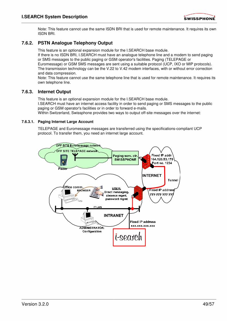
I.SEARCH System Description
Version 3.2.0 49/57
Note: This feature cannot use the same ISDN BRI that is used for remote maintenance. It requires its own
ISDN BRI.
7.6.2. PSTN Analogue Telephony Output
This feature is an optional expansion module for the I.SEARCH base module.
If there is no ISDN BRI, I.SEARCH must have an analogue telephone line and a modem to send paging
or SMS messages to the public paging or GSM operator's facilities. Paging (TELEPAGE or
Euromessage) or GSM SMS messages are sent using a suitable protocol (UCP, IXO or MIP protocols).
The transmission technology can be the V.22 to V.42 modem interfaces, with or without error correction
and data compression.
Note: This feature cannot use the same telephone line that is used for remote maintenance. It requires its
own telephone line.
7.6.3. Internet Output
This feature is an optional expansion module for the I.SEARCH base module.
I.SEARCH must have an internet access facility in order to send paging or SMS messages to the public
paging or GSM operator's facilities or in order to forward e-mails.
Within Switzerland, Swissphone provides two ways to output off-site messages over the internet:
7.6.3.1. Paging Internet Large Account
TELEPAGE and Euromessage messages are transferred using the specifications-compliant UCP
protocol. To transfer them, you need an internet large account.
Pager
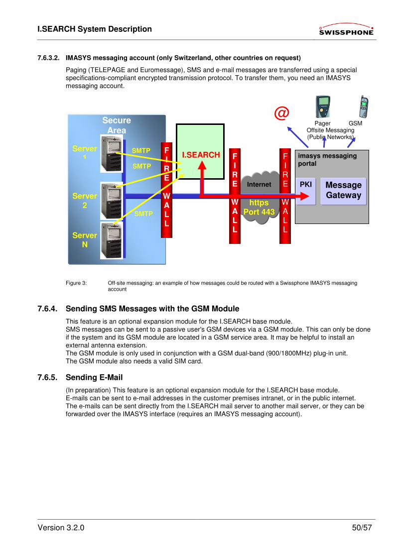
I.SEARCH System Description
Version 3.2.0 50/57
7.6.3.2. IMASYS messaging account (only Switzerland, other countries on request)
Paging (TELEPAGE and Euromessage), SMS and e-mail messages are transferred using a special
specifications-compliant encrypted transmission protocol. To transfer them, you need an IMASYS
messaging account.
Figure 3: Off-site messaging: an example of how messages could be routed with a Swissphone IMASYS messaging account
7.6.4. Sending SMS Messages with the GSM Module
This feature is an optional expansion module for the I.SEARCH base module.
SMS messages can be sent to a passive user's GSM devices via a GSM module. This can only be done
if the system and its GSM module are located in a GSM service area. It may be helpful to install an
external antenna extension.
The GSM module is only used in conjunction with a GSM dual-band (900/1800MHz) plug-in unit.
The GSM module also needs a valid SIM card.
7.6.5. Sending E-Mail
(In preparation) This feature is an optional expansion module for the I.SEARCH base module.
E-mails can be sent to e-mail addresses in the customer premises intranet, or in the public internet.
The e-mails can be sent directly from the I.SEARCH mail server to another mail server, or they can be
forwarded over the IMASYS interface (requires an IMASYS messaging account).
Internet
F I R E
W A L L
Secure Area
Server1
PKI Message Gateway
I.SEARCH F I R E
W A L L
SMTP
SMTP
SMTP
https Port 443
Server2
ServerN
imasys messaging portal
Pager GSM Offsite Messaging (Public Networks)
@
F I R E
W A L L
I.SEARCH System Description
Version 3.2.0 51/57
7.7. Off-Site Devices
Essentially all standard POCSAG alphanumeric receivers are supported. Recommended are Swissphone
DE9XX pagers.
7.8. System output
7.8.1. System Monitoring and Alarm
Hardware and software functionality is monitored. If an error occurs, an alarm can be activated. The
system alarms can consist of local bleeps or visual displays. Wherever possible, log functions should
record function failures.
7.8.2. Log Books
This feature is part of the I.SEARCH base module.
Various logs should be generated. The log data needs to be exportable.
Users with user classes > 3 have access to certain logs. For every user class > 3, you can define which
logs the class can access and who can export the logs.
Logs are kept on the following:
• Per input system
• Per output system
• Per LAN operation (who logs in, who performs what function, etc.)
• System events
In addition to the mandatory meaningful fields, additional fields from the database should also be defined.
These fields should allow customers to further process the data (outside the I.SEARCH system).
7.8.3. Raw Statistical Data
This feature is part of the I.SEARCH base module.
Users with a user class > 3 can export log files for further processing (internal accounting for generated
costs, usage, etc.). This way, you can track all the messages processed over a particular period of time
(per user, per output system, per input system, etc.).
Raw data can be generated either immediately, by selecting a menu button, or in a scheduled batch (the
1st of every month at 00:00, for example).
7.8.4. Lists
This feature is part of the I.SEARCH base module.
Users with a user class > 3 can retrieve and export database contents for further processing (address
book, user lists, processed alarm list, etc.).
The list results can be generated either immediately, by selecting a menu button, or in a scheduled batch
(the 1st of every month at 00:00, for example) using the backup function.
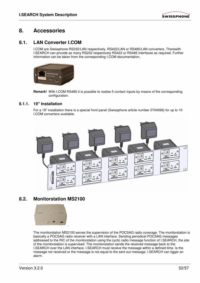
I.SEARCH System Description
Version 3.2.0 52/57
8. Accessories
8.1. LAN Converter I.COM
I.COM are Swissphone RS232/LAN respectively. RS422/LAN or RS485/LAN converters. Therewith I.SEARCH can provide as many RS232 respectively RS422 or RS485 interfaces as required. Further information can be taken from the corresponding I.COM documentation..
Remark! With I.COM RS485 it is possible to realise 5 contact inputs by means of the corresponding
configuration.
8.1.1. 19" Installation
For a 19" installation there is a special front panel (Swissphone article number 0704099) for up to 10 I.COM converters available.
8.2. Monitorstation MS2100
. The monitorstation MS2100 serves the supervision of the POCSAG radio coverage. The monitorstation is basically a POCSAG radio receiver with a LAN interface. Sending periodical POCSAG messages addressed to the RIC of the monitorstation using the cyclic radio message function of I.SEARCH, the site of the monitorstation is supervised. The monitorstation sends the received message back to the I.SEARCH over the LAN interface. I.SEARCH must receive the message within a defined time. Is the message not received or the message is not equal to the sent out message, I.SEARCH can tigger an alarm.
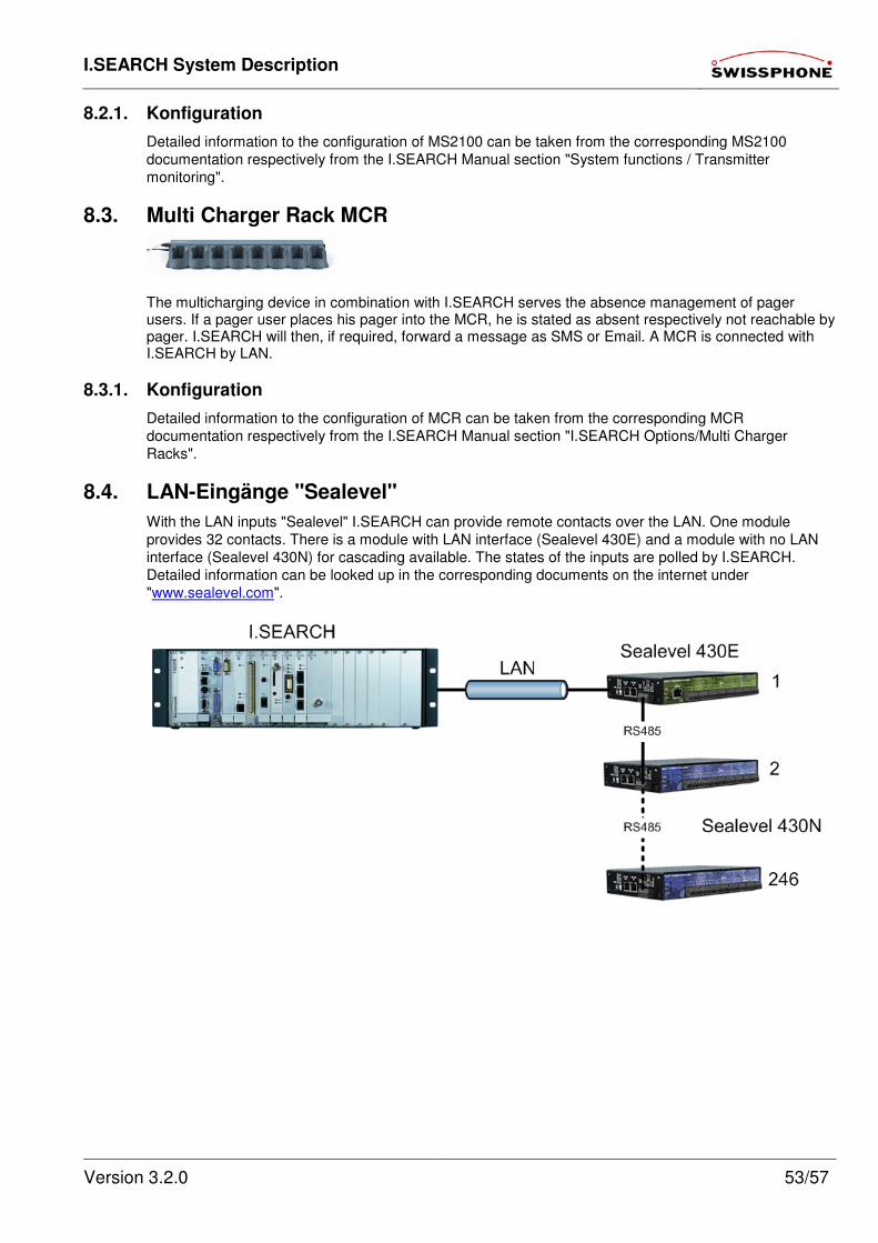
I.SEARCH System Description
Version 3.2.0 53/57
8.2.1. Konfiguration
Detailed information to the configuration of MS2100 can be taken from the corresponding MS2100
documentation respectively from the I.SEARCH Manual section "System functions / Transmitter
monitoring".
8.3. Multi Charger Rack MCR
The multicharging device in combination with I.SEARCH serves the absence management of pager users. If a pager user places his pager into the MCR, he is stated as absent respectively not reachable by pager. I.SEARCH will then, if required, forward a message as SMS or Email. A MCR is connected with I.SEARCH by LAN.
8.3.1. Konfiguration
Detailed information to the configuration of MCR can be taken from the corresponding MCR
documentation respectively from the I.SEARCH Manual section "I.SEARCH Options/Multi Charger
Racks".
8.4. LAN-Eingänge "Sealevel"
With the LAN inputs "Sealevel" I.SEARCH can provide remote contacts over the LAN. One module
provides 32 contacts. There is a module with LAN interface (Sealevel 430E) and a module with no LAN
interface (Sealevel 430N) for cascading available. The states of the inputs are polled by I.SEARCH.
Detailed information can be looked up in the corresponding documents on the internet under
"www.sealevel.com".
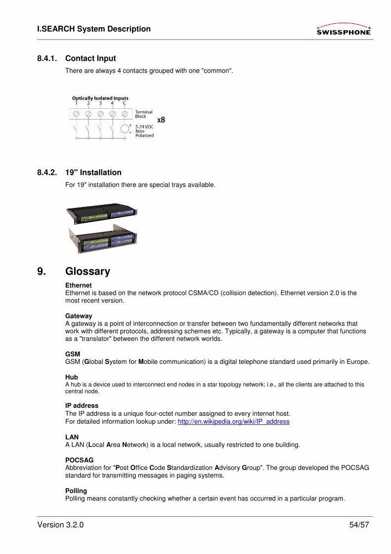
I.SEARCH System Description
Version 3.2.0 54/57
8.4.1. Contact Input
There are always 4 contacts grouped with one "common".
8.4.2. 19" Installation
For 19" installation there are special trays available.
9. Glossary
Ethernet Ethernet is based on the network protocol CSMA/CD (collision detection). Ethernet version 2.0 is the most recent version.
Gateway A gateway is a point of interconnection or transfer between two fundamentally different networks that work with different protocols, addressing schemes etc. Typically, a gateway is a computer that functions as a "translator" between the different network worlds.
GSM GSM (Global System for Mobile communication) is a digital telephone standard used primarily in Europe.
Hub A hub is a device used to interconnect end nodes in a star topology network; i.e., all the clients are attached to this central node.
IP address
The IP address is a unique four-octet number assigned to every internet host.
For detailed information lookup under: http://en.wikipedia.org/wiki/IP_address
LAN A LAN (Local Area Network) is a local network, usually restricted to one building.
POCSAG Abbreviation for "Post Office Code Standardization Advisory Group". The group developed the POCSAG standard for transmitting messages in paging systems.
Polling Polling means constantly checking whether a certain event has occurred in a particular program.
I.SEARCH System Description
Version 3.2.0 55/57
RIC Radio Identification Code. Address for your pager.
Server Servers are special computers in a network that can perform various functions:
• File servers provide data, programs and storage space-
• Mail servers process received or sent e-mails and distribute them to the appropriate accounts.
• Print servers send print jobs from various computers to a particular printer.
Subnet Mask
The subnet mask has the same format as an IP address (000.000.000.000) and states what network the
host belongs to.
For detailed information lookup under: http://en.wikipedia.org/wiki/IP_address TCP/IP TCP/IP ("Transmission Control Protocol/Internet Protocol") generally refers to an entire protocol suite developed by the U.S. Department of Defense (DoD) to interconnect computers in different networks. Today, TCP/IP is used in many LANs and is the base for the global internet.
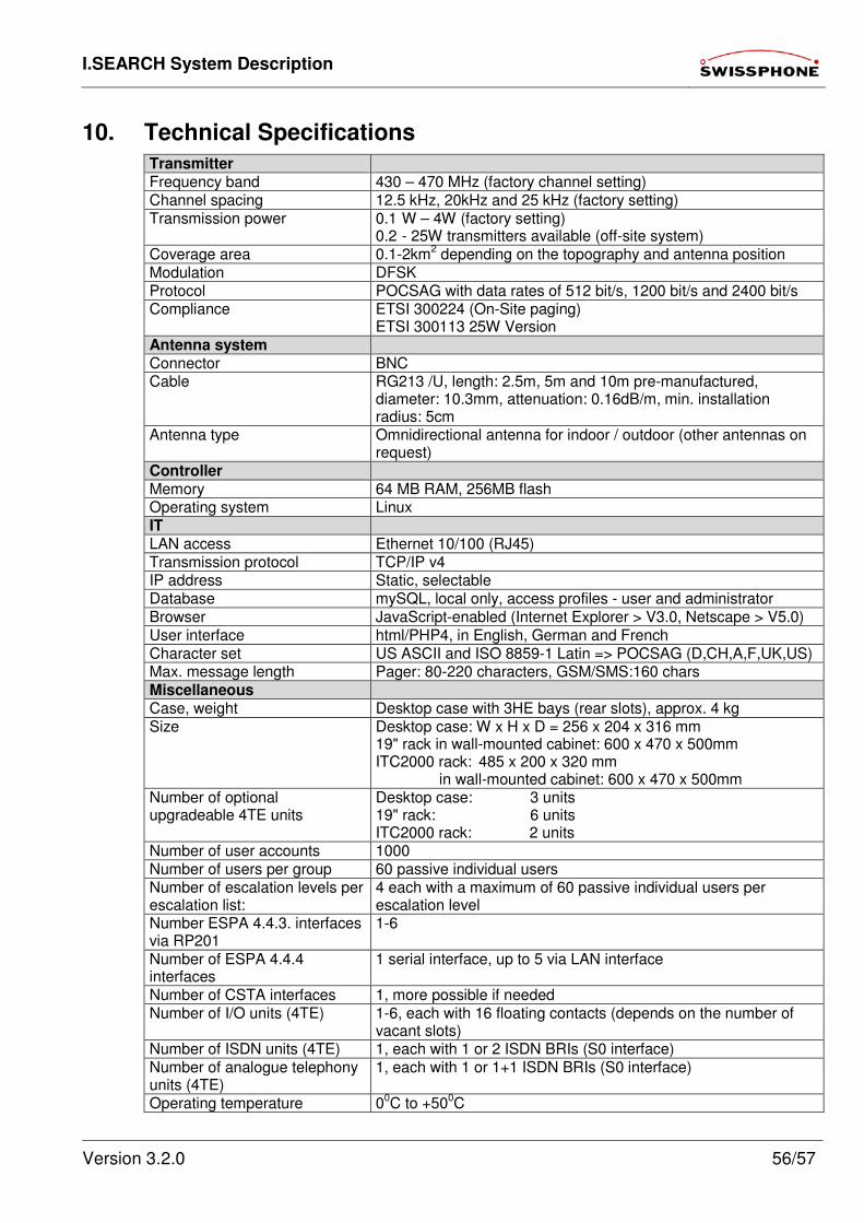
I.SEARCH System Description
Version 3.2.0 56/57
10. Technical Specifications
Transmitter Frequency band 430 – 470 MHz (factory channel setting) Channel spacing 12.5 kHz, 20kHz and 25 kHz (factory setting) Transmission power 0.1 W – 4W (factory setting)
0.2 - 25W transmitters available (off-site system) Coverage area 0.1-2km2 depending on the topography and antenna position Modulation DFSK Protocol POCSAG with data rates of 512 bit/s, 1200 bit/s and 2400 bit/s Compliance ETSI 300224 (On-Site paging)
ETSI 300113 25W Version Antenna system Connector BNC Cable RG213 /U, length: 2.5m, 5m and 10m pre-manufactured,
diameter: 10.3mm, attenuation: 0.16dB/m, min. installation radius: 5cm
Antenna type Omnidirectional antenna for indoor / outdoor (other antennas on request)
Controller Memory 64 MB RAM, 256MB flash Operating system Linux IT LAN access Ethernet 10/100 (RJ45) Transmission protocol TCP/IP v4 IP address Static, selectable Database mySQL, local only, access profiles - user and administrator Browser JavaScript-enabled (Internet Explorer > V3.0, Netscape > V5.0) User interface html/PHP4, in English, German and French Character set US ASCII and ISO 8859-1 Latin => POCSAG (D,CH,A,F,UK,US) Max. message length Pager: 80-220 characters, GSM/SMS:160 chars Miscellaneous Case, weight Desktop case with 3HE bays (rear slots), approx. 4 kg Size Desktop case: W x H x D = 256 x 204 x 316 mm
19" rack in wall-mounted cabinet: 600 x 470 x 500mm ITC2000 rack: 485 x 200 x 320 mm in wall-mounted cabinet: 600 x 470 x 500mm
Number of optional upgradeable 4TE units
Desktop case: 3 units 19" rack: 6 units ITC2000 rack: 2 units
Number of user accounts 1000 Number of users per group 60 passive individual users Number of escalation levels per escalation list:
4 each with a maximum of 60 passive individual users per escalation level
Number ESPA 4.4.3. interfaces via RP201
1-6
Number of ESPA 4.4.4 interfaces
1 serial interface, up to 5 via LAN interface
Number of CSTA interfaces 1, more possible if needed Number of I/O units (4TE) 1-6, each with 16 floating contacts (depends on the number of
vacant slots) Number of ISDN units (4TE) 1, each with 1 or 2 ISDN BRIs (S0 interface) Number of analogue telephony units (4TE)
1, each with 1 or 1+1 ISDN BRIs (S0 interface)
Operating temperature 00C to +500C
I.SEARCH System Description
Version 3.2.0 57/57
Power supply 230 VAC Conformity CE