Embed Size (px)
Citation preview
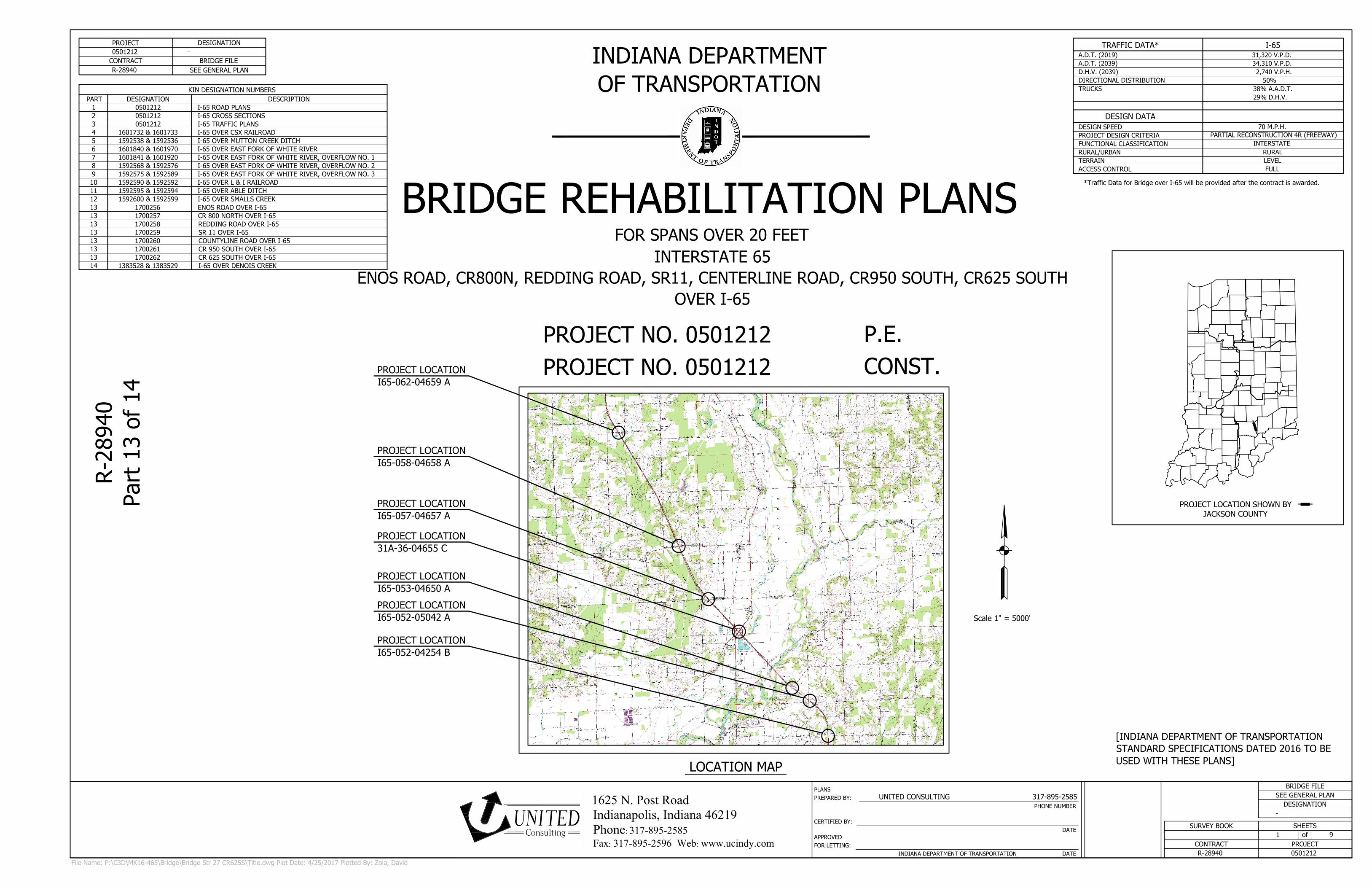
Scale 1" = 5000'
PROJECT DESIGNATION
CONTRACT
INDIANA DEPARTMENT OF TRANSPORTATION DATE
DATE
PHONE NUMBER
FOR LETTING:
APPROVED
CERTIFIED BY:
PREPARED BY:
PLANS
PROJECT LOCATION SHOWN BY
LOCATION MAP
PROJECT
DESIGNATION
CONTRACT
of
SHEETSSURVEY BOOK
BRIDGE FILE
BRIDGE FILE
1625 N. Post RoadIndianapolis, Indiana 46219Phone: 317-895-2585Fax: 317-895-2596 Web: www.ucindy.com
UNITEDConsulting
[INDIANA DEPARTMENT OF TRANSPORTATION
STANDARD SPECIFICATIONS DATED 2016 TO BE
USED WITH THESE PLANS]
P.E.
CONST.
FOR SPANS OVER 20 FEET
INDIANA DEPARTMENT
OF TRANSPORTATION
INTERSTATE 65
ENOS ROAD, CR800N, REDDING ROAD, SR11, CENTERLINE ROAD, CR950 SOUTH, CR625 SOUTH
OVER I-65
BRIDGE REHABILITATION PLANS
PROJECT NO. 0501212
-
SEE GENERAL PLANR-28940
0501212
R-28940 0501212
-
SEE GENERAL PLAN
1 9
PROJECT NO. 0501212
R-28940
Part 13 of 14
UNITED CONSULTING 317-895-2585
File Name: P:\C3D\MK16-465\Bridge\Bridge Str 27 CR625S\Title.dwg Plot Date: 4/25/2017 Plotted By: Zola, David
JACKSON COUNTY
DESIGN DATA
TERRAIN
RURAL/URBAN
70 M.P.H.
TRUCKS
FUNCTIONAL CLASSIFICATION
DESIGN SPEED
DIRECTIONAL DISTRIBUTION
D.H.V. (2039)
A.D.T. (2039)
A.D.T. (2019)
TRAFFIC DATA*
PROJECT DESIGN CRITERIA
ACCESS CONTROL
38% A.A.D.T.
2,740 V.P.H.
31,320 V.P.D.
34,310 V.P.D.
I-65
PARTIAL RECONSTRUCTION 4R (FREEWAY)
INTERSTATE
RURAL
LEVEL
FULL
50%
29% D.H.V.
PROJECT LOCATION
I65-052-04254 B
PROJECT LOCATION
I65-052-05042 A
PROJECT LOCATION
I65-053-04650 A
PROJECT LOCATION
31A-36-04655 C
PROJECT LOCATION
I65-057-04657 A
PROJECT LOCATION
I65-058-04658 A
PROJECT LOCATION
I65-062-04659 A
*Traffic Data for Bridge over I-65 will be provided after the contract is awarded.
KIN DESIGNATION NUMBERS
DESIGNATION DESCRIPTION
1601732 & 1601733 I-65 OVER CSX RAILROAD
1592538 & 1592536
1592568 & 1592576
1592575 & 1592589
1592590 & 1592592
1592595 & 1592594
I-65 OVER MUTTON CREEK DITCH
I-65 OVER EAST FORK OF WHITE RIVER, OVERFLOW NO. 1
1592600 & 1592599
I-65 OVER EAST FORK OF WHITE RIVER, OVERFLOW NO. 2
I-65 OVER EAST FORK OF WHITE RIVER, OVERFLOW NO. 3
I-65 OVER L & I RAILROAD
I-65 OVER ABLE DITCH
I-65 OVER SMALLS CREEK
0501212 I-65 ROAD PLANS
I-65 OVER EAST FORK OF WHITE RIVER
0501212 I-65 TRAFFIC PLANS
PART
1
0501212 I-65 CROSS SECTIONS2
3
4
5
6
7
8
9
10
11
1601840 & 1601970
1601841 & 1601920
12
13 ENOS ROAD OVER I-651700256
CR 800 NORTH OVER I-651700257
REDDING ROAD OVER I-651700258
SR 11 OVER I-651700259
COUNTYLINE ROAD OVER I-651700260
CR 950 SOUTH OVER I-651700261
CR 625 SOUTH OVER I-651700262
13
13
13
13
13
13
14 I-65 OVER DENOIS CREEK1383528 & 1383529

Aggreagate for End
Bent Backfill
Dense Graded
Subbase
Epoxy Coated
Threaded Bar
8"
Variable Depth
Concrete Girder
Slab
Type 1A Joint
6" ∅ Drain Pipe
Reinforced Concrete
Bridge Approach Slab
1.50
4
1
Polychloroprene
Sheeting
SCALE: 3/4" = 1'-0"
SEMI-INTEGRAL DETAIL
4.00
0.502.25 1.25
℄ Bearing
℄ Bent
UTILITIES
REVISIONS
SHEET No. DATE REVISION
SHEET NO. DESCRIPTION
1 TITLE
2 INDEX
3 GENERAL PLAN - ENOS ROAD OVER I-65
4 GENERAL PLAN - CR800 N OVER I-65
5 GENERAL PLAN - REDDING ROAD OVER I-65
6 GENERAL PLAN - SR 11 OVER I-65
7 GENERAL PLAN - COUNTYLINE ROAD OVER I-65
8 GENERAL PLAN - CR950 S OVER I-65
9 GENERAL PLAN - CR650 S OVER I-65
INDEXGENERAL NOTES
File Name: P:\C3D\MK16-465\Bridge\Bridge Str 27 CR625S\Index.dwg Plot Date: 4/25/2017 Plotted By: Zola, David
DESIGNED:
CHECKED:
DRAWN:
CHECKED:
RECOMMENDED
FOR APPROVAL
DESIGN ENGINEER DATE
SHEETS
of
VERTICAL SCALE
HORIZONTAL SCALE
CONTRACT
BRIDGE FILE
PROJECT
DESIGNATION
SURVEY BOOK
CJD DJZ
BSF CJD
AS SHOWN
AS SHOWN
SEE GENERAL PLAN
-
-
R-28940
2 9
0501212
INDEX
INDIANA
DEPARTMENT OF TRANSPORTATION
1625 N. Post RoadIndianapolis, IN 46219Phone 317-895-2585Fax 317-895-2596www.ucindy.com
ConsultingUNITED
NOTE TO REVIEWER:
Layout and Substructure Detail sheets will be provided
after award of the contract. The proposed scope of
work has been identified on the General Plan sheet.
The overpass bridge will be closed to traffic. A detour
route will be prepared after award of the contract.

℄ Enos Road
Varies
2'-3" to 7'-0"
29'-6" Out to Out Coping
0'-3"
1'-9"12'-0"1'-0"
26'-0" Clear Roadway
1'-9"12'-0" 1'-0"
3 Spaces @ 8'-3" = 24'-9"2'-4 1/2"
Limits of
Surface
Seal
Limits of
Surface
Seal
2'-4 1/2"
Proposed Profile
Grade
2.0% Slope
Variable Depth
Latex Modified
or Microsilica
Concrete Overlay
(1 1/2" Min.)2.0% Slope
Lane Lane
Partial and Full
Depth Patching at all
delaminated areas
65'-4" ℄ Brg. to ℄ Brg.37'-4" ℄ Brg to ℄ Brg.
20'-6"
Approach
26'-0" Clear Roadw
ay
29'-6" O
ut to O
ut Coping
12'-0" Lane
12'-0" Lane
Enos Road
℄ Pier No. 4
Sta. 108+65.33
℄ Bent No. 5
Sta. 109+03.16
℄ Pier No. 3
Sta.108+00.00
℄ Bent No. 1
Sta. 106+96.84
℄ Pier No. 2
Sta. 107+34.67
D
G
6 1/2"
Pvm't
Ledge
3'-0"
Berm
D
B C
B C
B C
B C
H
H
H
A
A
3'-0"
Berm
6 1/2"
Pvm't
Ledge
G
209'-0" Bridge Floor
65'-4" ℄ Brg. to ℄ Brg. 37'-4" ℄ Brg. to ℄ Brg.
20'-6"
Approach
E
E
E
E
F
F
A
A
DESIGNED:
CHECKED:
DRAWN:
CHECKED:
RECOMMENDED
FOR APPROVAL
DESIGN ENGINEER DATE
SHEETS
of
VERTICAL SCALE
HORIZONTAL SCALE
CONTRACT
BRIDGE FILE
PROJECT
DESIGNATION
SURVEY BOOK
CJD DJZ
BSF CJD
AS SHOWN
AS SHOWN
I65-052-04254 B
-
-
R-28940
3 9
0501212
GENERAL PLAN
ENOS ROAD OVER I-65
INDIANA
DEPARTMENT OF TRANSPORTATION
1625 N. Post RoadIndianapolis, IN 46219Phone 317-895-2585Fax 317-895-2596www.ucindy.com
ConsultingUNITED
SCALE: 3/8" = 1'-0"
EXISTING TYPICAL SECTION
File Name: P:\C3D\MK16-465\Bridge\Bridge Str 5A Enos\GP Str 5A Enos Rd.dwg Plot Date: 4/25/2017 Plotted By: Zola, David
Limits of Removal
1'-10"
SCALE: 3/32" = 1'-0"
PLAN VIEW
1. Existing plans for this structure are on file in the records unit of
the Indiana Department of Transportation as Bridge File
I65-052-04254 A.
2. Where new work is to be fitted to old work, the Contractor shall
check all dimensions and conditions in the field and report any
discrepancies to the Engineer and assume responsibility for their
correctness and fit of the new part to the old.
3. Reinforcing steel covering shall be 2 1/2" in top and 1" min. in
bottom of floor slabs, and 2" in all other parts, unless noted.
4. Surface seal all exposed surfaces of approach slabs, face of deck
coping and outer 6" of the underside of deck.
5. Stations shown are from the existing plans on file. The stations
will be updated for the proposed alignment for Final Deign.
Surface mill the existing surface and perform hydro-demolition to
remove any unsound concrete.
All delaminated areas of the bridge deck shall be partial or full
depth patched.
Existing bridge railing and copings to remain shall be surface sealed.
Remove and replace the reinforced concrete approach slabs.
LEGEND
A
B
C
D
E
F
G
H
GENERAL NOTES
Patch piers, superstructure and undersides of deck as necessary to
repair all delamination and spalling.
Remove and replace existing overlay
Convert the existing end bents to semi integral end bents. Sawcut
the existing mudwall to the bridge seat and remove 5 feet of the
deck. Jack and support the beams to replace the existing bearings
(See sheet 2).
Place a variable depth latex modified or micro silica concrete deck
overlay
DESIGN DATA
Designed for HS-20-44 loading in accordance with 2002 AASHTO
Standard Specifications for Highway Bridges 17th Edition and all
Subsequent Interim Specifications.
ULTIMATE DESIGN STRESSES
Class "A" Concrete f'c = 3,500 p.s.i.
Class "B" Concrete f'c = 3,000 p.s.i.
Class "C" Concrete f'c = 4,000 p.s.i.
Reinforcing Steel (Grade 60) fy = 60,000 p.s.i.
CONTINUOUS REINFORCED CONCRETE
GIRDER BRIDGE
4 SPANS: 37'-4", 65'-4", 65'-4", 37'-4"
26'-0" CLEAR ROADWAYS
SKEW: 0°
ENOS ROAD OVER I-65
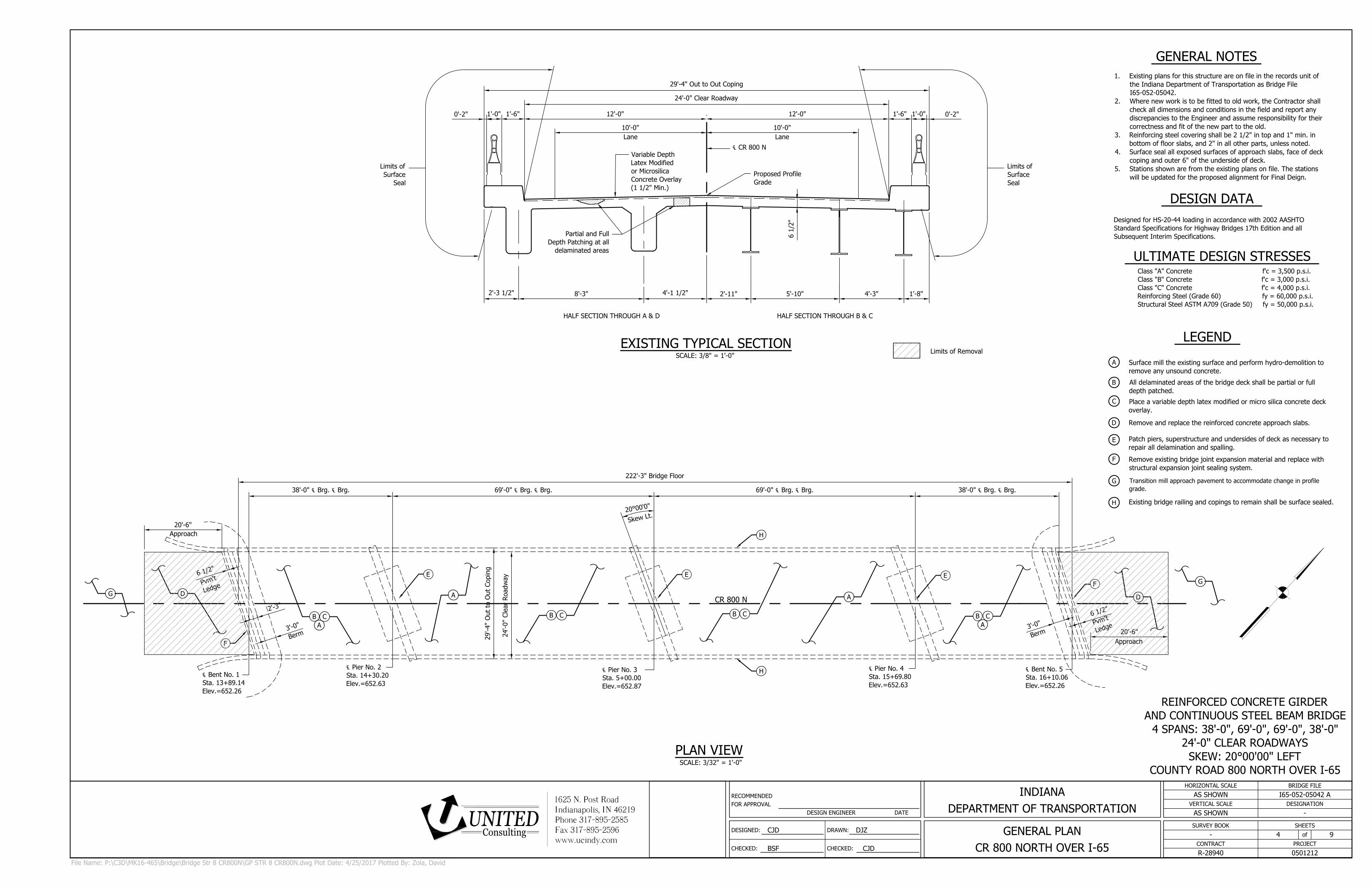
℄ CR 800 N
29'-4" Out to Out Coping
0'-2"1'-0"
10'-0"
1'-6"
24'-0" Clear Roadway
2'-3 1/2"
Limits of
Surface
Seal
1'-8"
Proposed Profile
Grade
Variable Depth
Latex Modified
or Microsilica
Concrete Overlay
(1 1/2" Min.)
Lane
12'-0"0'-2"
1'-0"1'-6"12'-0"
10'-0"
Lane
Limits of
Surface
Seal
8'-3"
4'-1 1/2"
2'-11" 5'-10" 4'-3"
6 1/2"
Partial and Full
Depth Patching at all
delaminated areas
69'-0" ℄ Brg. ℄ Brg.38'-0" ℄ Brg. ℄ Brg.
20'-6"
Approach
20'-6"
Approach
24'-0" Clear Roadw
ay
29'-4" O
ut to O
ut Coping
2
0
°
0
0
'0
"
CR 800 N
℄ Pier No. 4
Sta. 15+69.80
Elev.=652.63
℄ Bent No. 5
Sta. 16+10.06
Elev.=652.26
℄ Pier No. 3
Sta. 5+00.00
Elev.=652.87
℄ Bent No. 1
Sta. 13+89.14
Elev.=652.26
℄ Pier No. 2
Sta. 14+30.20
Elev.=652.63
F
D
H
2
'
-
3
"
6
1
/
2
"
P
v
m
'
t
L
e
d
g
e
3
'
-
0
"
B
e
r
m
F
D
B C
B C
B C
B C
E
E
E
A
A
3
'
-
0
"
B
e
r
m
6
1
/
2
"
P
v
m
'
t
L
e
d
g
e
H
S
k
e
w
L
t
.
69'-0" ℄ Brg. ℄ Brg. 38'-0" ℄ Brg. ℄ Brg.
222'-3" Bridge Floor
G
A
A
G
DESIGNED:
CHECKED:
DRAWN:
CHECKED:
RECOMMENDED
FOR APPROVAL
DESIGN ENGINEER DATE
SHEETS
of
VERTICAL SCALE
HORIZONTAL SCALE
CONTRACT
BRIDGE FILE
PROJECT
DESIGNATION
SURVEY BOOK
CJD DJZ
BSF CJD
AS SHOWN
AS SHOWN
I65-052-05042 A
-
-
R-28940
4 9
0501212
GENERAL PLAN
CR 800 NORTH OVER I-65
INDIANA
DEPARTMENT OF TRANSPORTATION
1625 N. Post RoadIndianapolis, IN 46219Phone 317-895-2585Fax 317-895-2596www.ucindy.com
ConsultingUNITED
SCALE: 3/8" = 1'-0"
EXISTING TYPICAL SECTION
File Name: P:\C3D\MK16-465\Bridge\Bridge Str 8 CR800N\GP STR 8 CR800N.dwg Plot Date: 4/25/2017 Plotted By: Zola, David
Limits of Removal
HALF SECTION THROUGH A & D HALF SECTION THROUGH B & C
SCALE: 3/32" = 1'-0"
PLAN VIEW
1. Existing plans for this structure are on file in the records unit of
the Indiana Department of Transportation as Bridge File
I65-052-05042.
2. Where new work is to be fitted to old work, the Contractor shall
check all dimensions and conditions in the field and report any
discrepancies to the Engineer and assume responsibility for their
correctness and fit of the new part to the old.
3. Reinforcing steel covering shall be 2 1/2" in top and 1" min. in
bottom of floor slabs, and 2" in all other parts, unless noted.
4. Surface seal all exposed surfaces of approach slabs, face of deck
coping and outer 6" of the underside of deck.
5. Stations shown are from the existing plans on file. The stations
will be updated for the proposed alignment for Final Deign.
Surface mill the existing surface and perform hydro-demolition to
remove any unsound concrete.
All delaminated areas of the bridge deck shall be partial or full
depth patched.
Place a variable depth latex modified or micro silica concrete deck
overlay.
Remove and replace the reinforced concrete approach slabs.
Existing bridge railing and copings to remain shall be surface sealed.
Patch piers, superstructure and undersides of deck as necessary to
repair all delamination and spalling.
Transition mill approach pavement to accommodate change in profile
grade.
LEGEND
A
B
C
D
E
F
G
H
GENERAL NOTES
Remove existing bridge joint expansion material and replace with
structural expansion joint sealing system.
DESIGN DATA
Designed for HS-20-44 loading in accordance with 2002 AASHTO
Standard Specifications for Highway Bridges 17th Edition and all
Subsequent Interim Specifications.
ULTIMATE DESIGN STRESSES
Class "A" Concrete f'c = 3,500 p.s.i.
Class "B" Concrete f'c = 3,000 p.s.i.
Class "C" Concrete f'c = 4,000 p.s.i.
Reinforcing Steel (Grade 60) fy = 60,000 p.s.i.
Structural Steel ASTM A709 (Grade 50) fy = 50,000 p.s.i.
REINFORCED CONCRETE GIRDER
AND CONTINUOUS STEEL BEAM BRIDGE
4 SPANS: 38'-0", 69'-0", 69'-0", 38'-0"
24'-0" CLEAR ROADWAYS
SKEW: 20°00'00" LEFT
COUNTY ROAD 800 NORTH OVER I-65
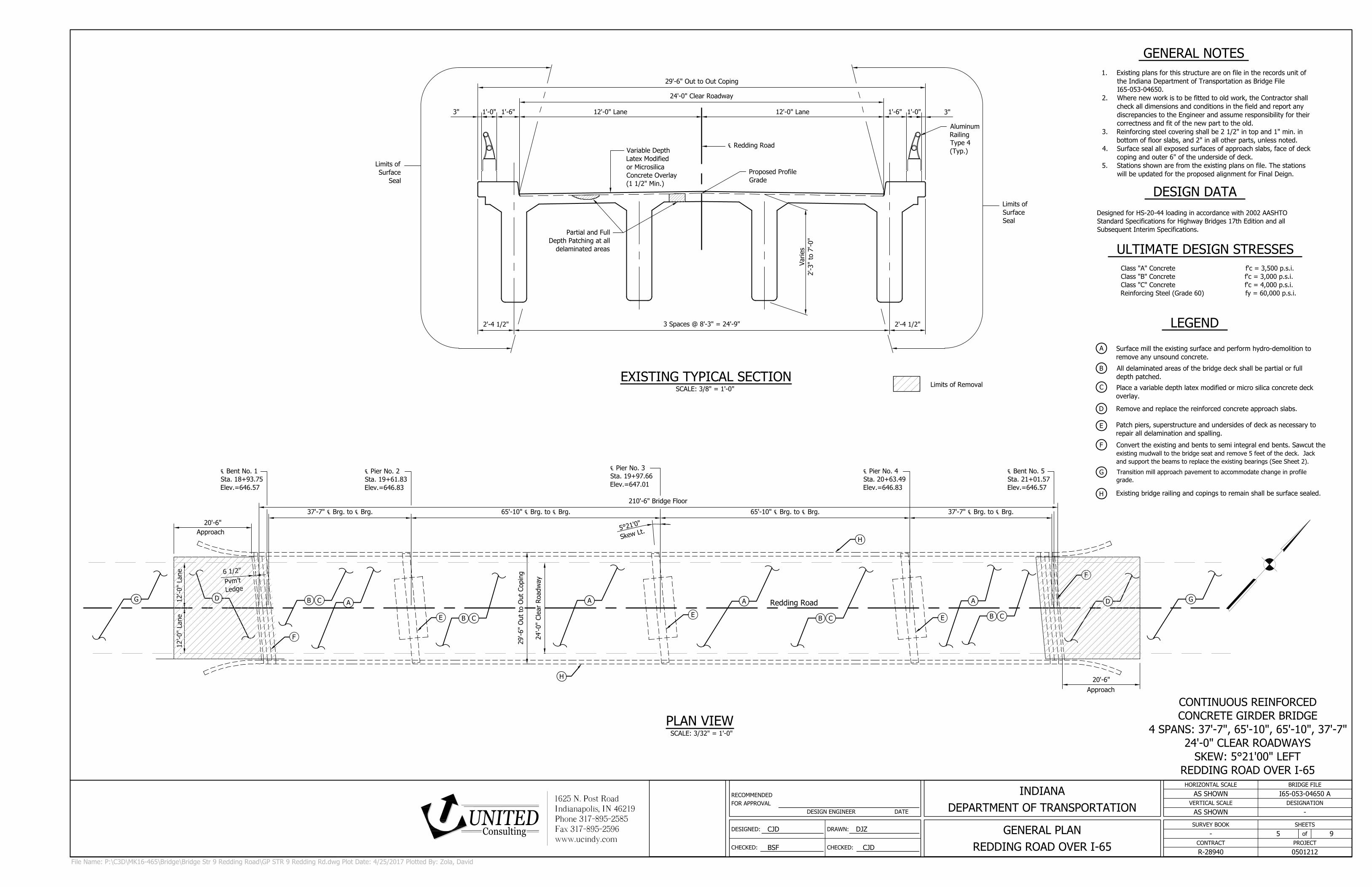
29'-6" Out to Out Coping
℄ Redding Road
24'-0" Clear Roadway
Limits of
Surface
Seal
Proposed Profile
Grade
Variable Depth
Latex Modified
or Microsilica
Concrete Overlay
(1 1/2" Min.)
12'-0" Lane3"
1'-0"1'-6"12'-0" Lane
Limits of
Surface
Seal
3" 1'-0" 1'-6"
Partial and Full
Depth Patching at all
delaminated areas
Aluminum
Railing
Type 4
(Typ.)
Varies
2'-3" to 7'-0"
2'-4 1/2"3 Spaces @ 8'-3" = 24'-9"
2'-4 1/2"
20'-6"
Approach
20'-6"
Approach
24'-0" Clear Roadw
ay
29'-6" O
ut to O
ut Coping
12'-0" Lane
12'-0" Lane
6 1
/2"
Pvm
't
Ledge
℄ Bent No. 1
Sta. 18+93.75
Elev.=646.57
℄ Pier No. 2
Sta. 19+61.83
Elev.=646.83
℄ Pier No. 3
Sta. 19+97.66
Elev.=647.01
℄ Pier No. 4
Sta. 20+63.49
Elev.=646.83
℄ Bent No. 5
Sta. 21+01.57
Elev.=646.57
A
A
A
A
Redding Road
D
D
F
F
E
B CB C
H
H
5
°
2
1
'0
"
S
k
e
w
L
t
.
B C
B C
E
E
65'-10" ℄ Brg. to ℄ Brg.37'-7" ℄ Brg. to ℄ Brg.
210'-6" Bridge Floor
65'-10" ℄ Brg. to ℄ Brg. 37'-7" ℄ Brg. to ℄ Brg.
GG
DESIGNED:
CHECKED:
DRAWN:
CHECKED:
RECOMMENDED
FOR APPROVAL
DESIGN ENGINEER DATE
SHEETS
of
VERTICAL SCALE
HORIZONTAL SCALE
CONTRACT
BRIDGE FILE
PROJECT
DESIGNATION
SURVEY BOOK
CJD DJZ
BSF CJD
AS SHOWN
AS SHOWN
I65-053-04650 A
-
-
R-28940
5 9
0501212
GENERAL PLAN
REDDING ROAD OVER I-65
INDIANA
DEPARTMENT OF TRANSPORTATION
1625 N. Post RoadIndianapolis, IN 46219Phone 317-895-2585Fax 317-895-2596www.ucindy.com
ConsultingUNITED
SCALE: 3/8" = 1'-0"
EXISTING TYPICAL SECTION
File Name: P:\C3D\MK16-465\Bridge\Bridge Str 9 Redding Road\GP STR 9 Redding Rd.dwg Plot Date: 4/25/2017 Plotted By: Zola, David
Limits of Removal
SCALE: 3/32" = 1'-0"
PLAN VIEW
1. Existing plans for this structure are on file in the records unit of
the Indiana Department of Transportation as Bridge File
I65-053-04650.
2. Where new work is to be fitted to old work, the Contractor shall
check all dimensions and conditions in the field and report any
discrepancies to the Engineer and assume responsibility for their
correctness and fit of the new part to the old.
3. Reinforcing steel covering shall be 2 1/2" in top and 1" min. in
bottom of floor slabs, and 2" in all other parts, unless noted.
4. Surface seal all exposed surfaces of approach slabs, face of deck
coping and outer 6" of the underside of deck.
5. Stations shown are from the existing plans on file. The stations
will be updated for the proposed alignment for Final Deign.
Surface mill the existing surface and perform hydro-demolition to
remove any unsound concrete.
All delaminated areas of the bridge deck shall be partial or full
depth patched.
Place a variable depth latex modified or micro silica concrete deck
overlay.
Remove and replace the reinforced concrete approach slabs.
Existing bridge railing and copings to remain shall be surface sealed.
Patch piers, superstructure and undersides of deck as necessary to
repair all delamination and spalling.
Convert the existing and bents to semi integral end bents. Sawcut the
existing mudwall to the bridge seat and remove 5 feet of the deck. Jack
and support the beams to replace the existing bearings (See Sheet 2).
Transition mill approach pavement to accommodate change in profile
grade.
LEGEND
A
B
C
D
E
F
G
H
GENERAL NOTES
DESIGN DATA
Designed for HS-20-44 loading in accordance with 2002 AASHTO
Standard Specifications for Highway Bridges 17th Edition and all
Subsequent Interim Specifications.
ULTIMATE DESIGN STRESSES
Class "A" Concrete f'c = 3,500 p.s.i.
Class "B" Concrete f'c = 3,000 p.s.i.
Class "C" Concrete f'c = 4,000 p.s.i.
Reinforcing Steel (Grade 60) fy = 60,000 p.s.i.
CONTINUOUS REINFORCED
CONCRETE GIRDER BRIDGE
4 SPANS: 37'-7", 65'-10", 65'-10", 37'-7"
24'-0" CLEAR ROADWAYS
SKEW: 5°21'00" LEFT
REDDING ROAD OVER I-65
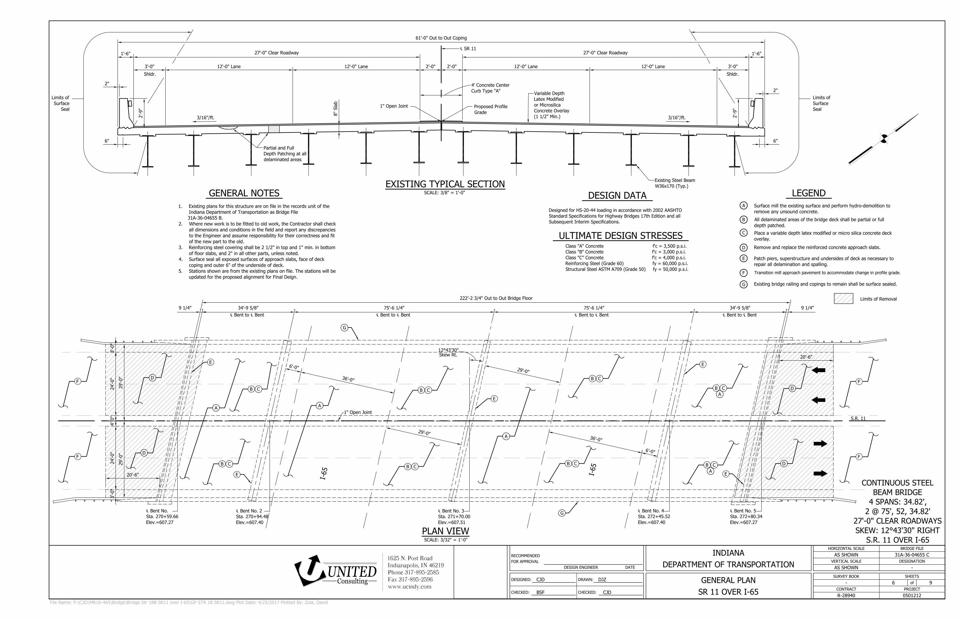
61'-0" Out to Out Coping
27'-0" Clear Roadway
℄ SR 11
12'-0" Lane12'-0" Lane
1'-6"
2"
2'-0"3'-0"
Shldr.
2'-9"
6"
27'-0" Clear Roadway
12'-0" Lane 12'-0" Lane
1'-6"
2"
2'-0" 3'-0"
Shldr.
2'-9"
6"
Proposed Profile
Grade
Variable Depth
Latex Modified
or Microsilica
Concrete Overlay
(1 1/2" Min.)
Partial and Full
Depth Patching at all
delaminated areas
Limits of
Surface
Seal
Limits of
Surface
Seal
8" Slab
1" Open Joint
3/16"/ft. 3/16"/ft.
4' Concrete Center
Curb Type "A"
Existing Steel Beam
W36x170 (Typ.)
I
-
6
5
S.R. 11
I
-
6
5
3
6
'-
0
"
2
9
'-
0
"
2
9
'-
0
"
3
6
'-
0
"
1" Open Joint
6
'-
0
"
6
'-
0
"
222'-2 3/4" Out to Out Bridge Floor
34'-9 5/8" 75'-6 1/4" 75'-6 1/4" 9 1/4"34'-9 5/8"9 1/4"
12°43'30"
Skew Rt.
4'-0"
24'-0"
3'-0"
24'-0"
3'-0"
℄ Bent No.
Sta. 270+59.66
Elev.=607.27
20'-6"
20'-6"
29'-0"
29'-0"
℄ Bent No. 2
Sta. 270+94.48
Elev.=607.40
℄ Bent No. 3
Sta. 271+70.00
Elev.=607.51
℄ Bent No. 4
Sta. 272+45.52
Elev.=607.40
℄ Bent No. 5
Sta. 272+80.34
Elev.=607.27
℄ Bent to ℄ Bent℄ Bent to ℄ Bent℄ Bent to ℄ Bent℄ Bent to ℄ Bent
G
B C
A
A
F
A
B C
B C
B C
B C
B C
B C
E
E
E
E
E
G
D
F
D
F
F
D
D
A
B C
A
DESIGNED:
CHECKED:
DRAWN:
CHECKED:
RECOMMENDED
FOR APPROVAL
DESIGN ENGINEER DATE
SHEETS
of
VERTICAL SCALE
HORIZONTAL SCALE
CONTRACT
BRIDGE FILE
PROJECT
DESIGNATION
SURVEY BOOK
CJD DJZ
BSF CJD
AS SHOWN
AS SHOWN
31A-36-04655 C
-
-
R-28940
6 9
0501212
GENERAL PLAN
SR 11 OVER I-65
INDIANA
DEPARTMENT OF TRANSPORTATION
1625 N. Post RoadIndianapolis, IN 46219Phone 317-895-2585Fax 317-895-2596www.ucindy.com
ConsultingUNITED
SCALE: 3/8" = 1'-0"
EXISTING TYPICAL SECTION
File Name: P:\C3D\MK16-465\Bridge\Bridge Str 18B SR11 over I-65\GP STR 18 SR11.dwg Plot Date: 4/25/2017 Plotted By: Zola, David
Limits of Removal
GENERAL NOTES
1. Existing plans for this structure are on file in the records unit of the
Indiana Department of Transportation as Bridge File
31A-36-04655 B.
2. Where new work is to be fitted to old work, the Contractor shall check
all dimensions and conditions in the field and report any discrepancies
to the Engineer and assume responsibility for their correctness and fit
of the new part to the old.
3. Reinforcing steel covering shall be 2 1/2" in top and 1" min. in bottom
of floor slabs, and 2" in all other parts, unless noted.
4. Surface seal all exposed surfaces of approach slabs, face of deck
coping and outer 6" of the underside of deck.
5. Stations shown are from the existing plans on file. The stations will be
updated for the proposed alignment for Final Deign.
Surface mill the existing surface and perform hydro-demolition to
remove any unsound concrete.
All delaminated areas of the bridge deck shall be partial or full
depth patched.
Place a variable depth latex modified or micro silica concrete deck
overlay.
Remove and replace the reinforced concrete approach slabs.
Existing bridge railing and copings to remain shall be surface sealed.
Patch piers, superstructure and undersides of deck as necessary to
repair all delamination and spalling.
Transition mill approach pavement to accommodate change in profile grade.
LEGEND
A
B
C
D
E
F
G
SCALE: 3/32" = 1'-0"
PLAN VIEW
DESIGN DATA
Designed for HS-20-44 loading in accordance with 2002 AASHTO
Standard Specifications for Highway Bridges 17th Edition and all
Subsequent Interim Specifications.
ULTIMATE DESIGN STRESSES
Class "A" Concrete f'c = 3,500 p.s.i.
Class "B" Concrete f'c = 3,000 p.s.i.
Class "C" Concrete f'c = 4,000 p.s.i.
Reinforcing Steel (Grade 60) fy = 60,000 p.s.i.
Structural Steel ASTM A709 (Grade 50) fy = 50,000 p.s.i.
CONTINUOUS STEEL
BEAM BRIDGE
4 SPANS: 34.82',
2 @ 75', 52, 34.82'
27'-0" CLEAR ROADWAYS
SKEW: 12°43'30" RIGHT
S.R. 11 OVER I-65
29'-6" Out to Out Coping
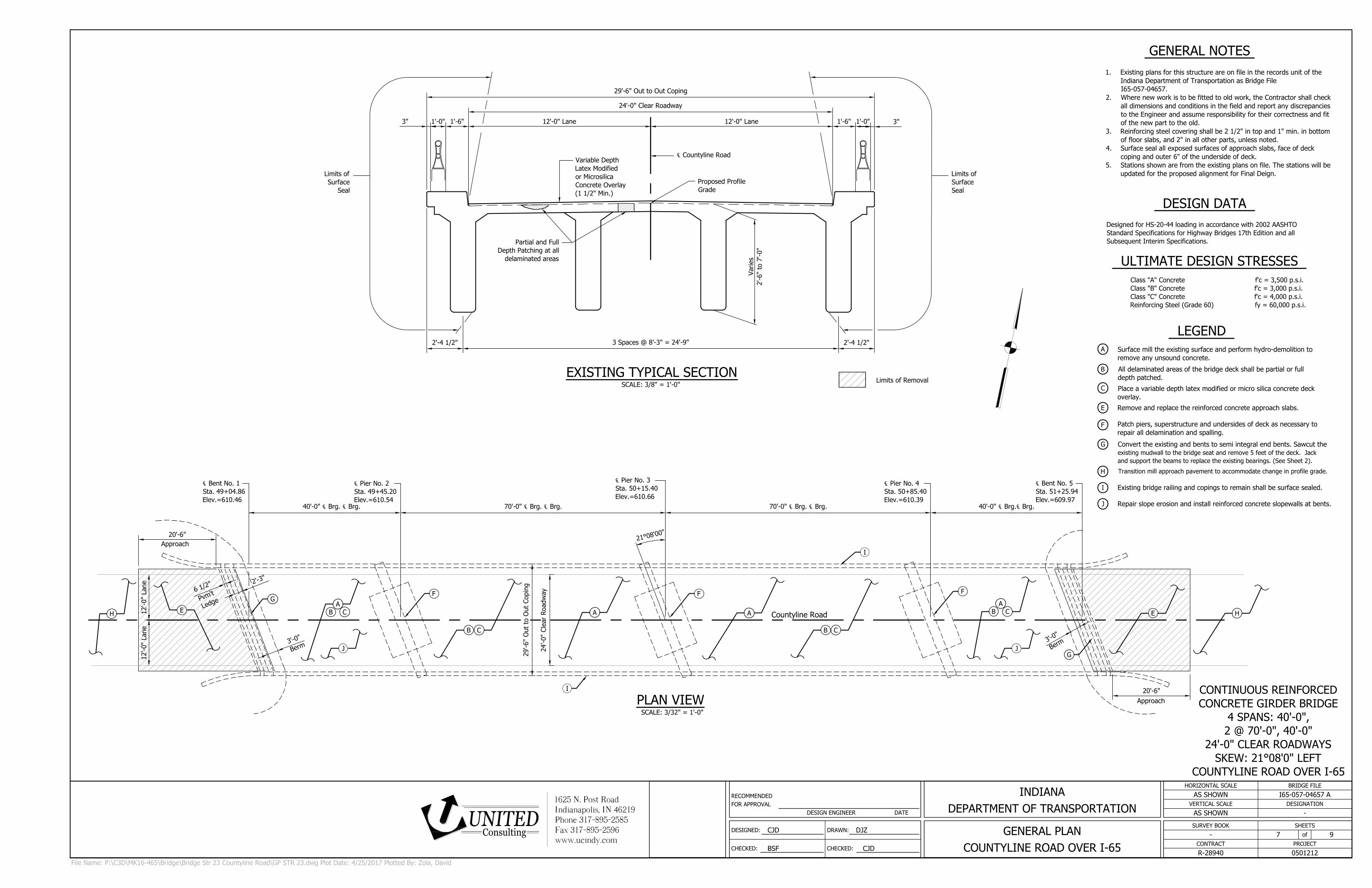
℄ Countyline Road
24'-0" Clear Roadway
Limits of
Surface
Seal
Proposed Profile
Grade
Variable Depth
Latex Modified
or Microsilica
Concrete Overlay
(1 1/2" Min.)
12'-0" Lane3"
1'-0"1'-6"12'-0" Lane
Limits of
Surface
Seal
3" 1'-0" 1'-6"
Partial and Full
Depth Patching at all
delaminated areas
Varies
2'-6" to 7'-0"
3 Spaces @ 8'-3" = 24'-9"2'-4 1/2" 2'-4 1/2"
70'-0" ℄ Brg. ℄ Brg. 70'-0" ℄ Brg. ℄ Brg.40'-0" ℄ Brg. ℄ Brg. 40'-0" ℄ Brg.℄ Brg.
20'-6"
Approach
20'-6"
Approach
2
1
°
0
8
'0
0
"
24'-0" Clear Roadw
ay
29'-6" O
ut to O
ut Coping
12'-0" Lane
12'-0" Lane
2
'
-
3
"
6
1
/
2
"
P
v
m
'
t
L
e
d
g
e
3
'
-
0
"
B
e
r
m
℄ Bent No. 1
Sta. 49+04.86
Elev.=610.46
℄ Pier No. 2
Sta. 49+45.20
Elev.=610.54
℄ Pier No. 3
Sta. 50+15.40
Elev.=610.66
℄ Pier No. 4
Sta. 50+85.40
Elev.=610.39
℄ Bent No. 5
Sta. 51+25.94
Elev.=609.97
A
A
A
A
Countyline Road
G
G
H
E
F
FF
B CB C
I
I
3
'
-
0
"
B
e
r
m
E
H
J
B C
B C
J
DESIGNED:
CHECKED:
DRAWN:
CHECKED:
RECOMMENDED
FOR APPROVAL
DESIGN ENGINEER DATE
SHEETS
of
VERTICAL SCALE
HORIZONTAL SCALE
CONTRACT
BRIDGE FILE
PROJECT
DESIGNATION
SURVEY BOOK
CJD DJZ
BSF CJD
AS SHOWN
AS SHOWN
I65-057-04657 A
-
-
R-28940
7 9
0501212
GENERAL PLAN
COUNTYLINE ROAD OVER I-65
INDIANA
DEPARTMENT OF TRANSPORTATION
1625 N. Post RoadIndianapolis, IN 46219Phone 317-895-2585Fax 317-895-2596www.ucindy.com
ConsultingUNITED
SCALE: 3/8" = 1'-0"
EXISTING TYPICAL SECTION
File Name: P:\C3D\MK16-465\Bridge\Bridge Str 23 Countyline Road\GP STR 23.dwg Plot Date: 4/25/2017 Plotted By: Zola, David
Limits of Removal
SCALE: 3/32" = 1'-0"
PLAN VIEW
GENERAL NOTES
1. Existing plans for this structure are on file in the records unit of the
Indiana Department of Transportation as Bridge File
I65-057-04657.
2. Where new work is to be fitted to old work, the Contractor shall check
all dimensions and conditions in the field and report any discrepancies
to the Engineer and assume responsibility for their correctness and fit
of the new part to the old.
3. Reinforcing steel covering shall be 2 1/2" in top and 1" min. in bottom
of floor slabs, and 2" in all other parts, unless noted.
4. Surface seal all exposed surfaces of approach slabs, face of deck
coping and outer 6" of the underside of deck.
5. Stations shown are from the existing plans on file. The stations will be
updated for the proposed alignment for Final Deign.
Surface mill the existing surface and perform hydro-demolition to
remove any unsound concrete.
All delaminated areas of the bridge deck shall be partial or full
depth patched.
Place a variable depth latex modified or micro silica concrete deck
overlay.
Remove and replace the reinforced concrete approach slabs.
Existing bridge railing and copings to remain shall be surface sealed.
Patch piers, superstructure and undersides of deck as necessary to
repair all delamination and spalling.
Convert the existing and bents to semi integral end bents. Sawcut the
existing mudwall to the bridge seat and remove 5 feet of the deck. Jack
and support the beams to replace the existing bearings. (See Sheet 2).
Transition mill approach pavement to accommodate change in profile grade.
LEGEND
A
B
C
E
F
G
H
I
DESIGN DATA
Designed for HS-20-44 loading in accordance with 2002 AASHTO
Standard Specifications for Highway Bridges 17th Edition and all
Subsequent Interim Specifications.
ULTIMATE DESIGN STRESSES
Class "A" Concrete f'c = 3,500 p.s.i.
Class "B" Concrete f'c = 3,000 p.s.i.
Class "C" Concrete f'c = 4,000 p.s.i.
Reinforcing Steel (Grade 60) fy = 60,000 p.s.i.
CONTINUOUS REINFORCED
CONCRETE GIRDER BRIDGE
4 SPANS: 40'-0",
2 @ 70'-0", 40'-0"
24'-0" CLEAR ROADWAYS
SKEW: 21°08'0" LEFT
COUNTYLINE ROAD OVER I-65
Repair slope erosion and install reinforced concrete slopewalls at bents.J
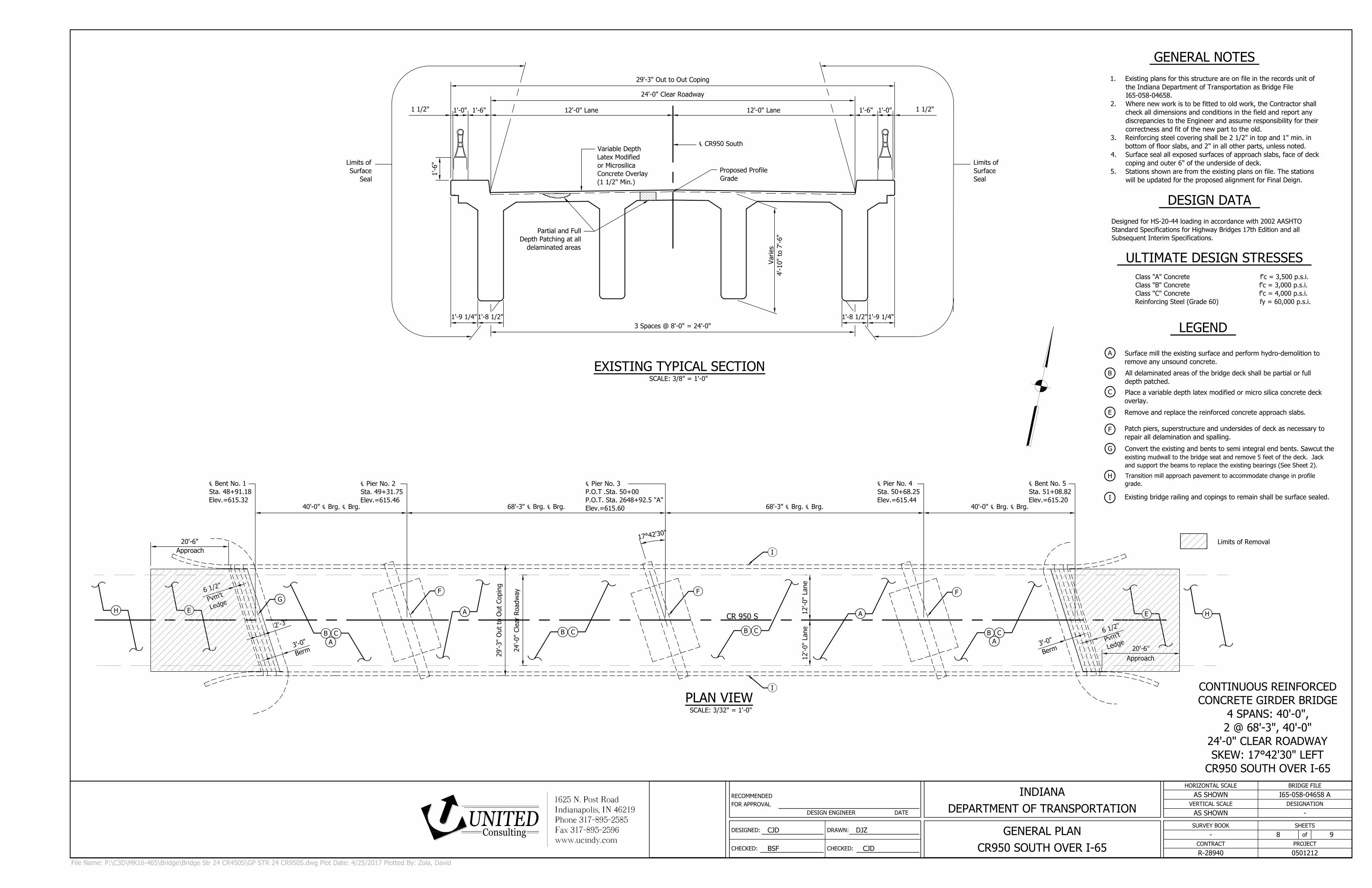
29'-3" Out to Out Coping
℄ CR950 South
24'-0" Clear Roadway
Limits of
Surface
Seal
Proposed Profile
Grade
Variable Depth
Latex Modified
or Microsilica
Concrete Overlay
(1 1/2" Min.)
12'-0" Lane 12'-0" Lane
Limits of
Surface
Seal
1 1/2"
1'-0" 1'-6"
Partial and Full
Depth Patching at all
delaminated areas
Varies
4'-10" to 7'-6"
1'-9 1/4"1'-8 1/2"
3 Spaces @ 8'-0" = 24'-0"
1'-9 1/4"1'-8 1/2"
1 1/2"
1'-0"1'-6"
1'-6"
68'-3" ℄ Brg. ℄ Brg. 68'-3" ℄ Brg. ℄ Brg.40'-0" ℄ Brg. ℄ Brg. 40'-0" ℄ Brg. ℄ Brg.
20'-6"
Approach
20'-6"
Approach
24'-0" Clear Roadw
ay
29'-3" O
ut to O
ut Coping
1
7
°
4
2
'3
0
"
12'-0" Lane
12'-0" Lane
CR 950 S
℄ Pier No. 4
Sta. 50+68.25
Elev.=615.44
℄ Bent No. 5
Sta. 51+08.82
Elev.=615.20
℄ Pier No. 3
P.O.T .Sta. 50+00
P.O.T. Sta. 2648+92.5 "A"
Elev.=615.60
℄ Bent No. 1
Sta. 48+91.18
Elev.=615.32
℄ Pier No. 2
Sta. 49+31.75
Elev.=615.46
H
I
2
'
-
3
"
6
1
/
2
"
P
v
m
'
t
L
e
d
g
e
3
'
-
0
"
B
e
r
m
G
E
B C
B C
B C
B C
F
F
F
A
A
3
'
-
0
"
B
e
r
m
6
1
/
2
"
P
v
m
'
t
L
e
d
g
e
I
E
H
A
A
DESIGNED:
CHECKED:
DRAWN:
CHECKED:
RECOMMENDED
FOR APPROVAL
DESIGN ENGINEER DATE
SHEETS
of
VERTICAL SCALE
HORIZONTAL SCALE
CONTRACT
BRIDGE FILE
PROJECT
DESIGNATION
SURVEY BOOK
CJD DJZ
BSF CJD
AS SHOWN
AS SHOWN
I65-058-04658 A
-
-
R-28940
8 9
0501212
GENERAL PLAN
CR950 SOUTH OVER I-65
INDIANA
DEPARTMENT OF TRANSPORTATION
1625 N. Post RoadIndianapolis, IN 46219Phone 317-895-2585Fax 317-895-2596www.ucindy.com
ConsultingUNITED
SCALE: 3/8" = 1'-0"
EXISTING TYPICAL SECTION
File Name: P:\C3D\MK16-465\Bridge\Bridge Str 24 CR450S\GP STR 24 CR950S.dwg Plot Date: 4/25/2017 Plotted By: Zola, David
Limits of Removal
SCALE: 3/32" = 1'-0"
PLAN VIEW
GENERAL NOTES
1. Existing plans for this structure are on file in the records unit of
the Indiana Department of Transportation as Bridge File
I65-058-04658.
2. Where new work is to be fitted to old work, the Contractor shall
check all dimensions and conditions in the field and report any
discrepancies to the Engineer and assume responsibility for their
correctness and fit of the new part to the old.
3. Reinforcing steel covering shall be 2 1/2" in top and 1" min. in
bottom of floor slabs, and 2" in all other parts, unless noted.
4. Surface seal all exposed surfaces of approach slabs, face of deck
coping and outer 6" of the underside of deck.
5. Stations shown are from the existing plans on file. The stations
will be updated for the proposed alignment for Final Deign.
Surface mill the existing surface and perform hydro-demolition to
remove any unsound concrete.
All delaminated areas of the bridge deck shall be partial or full
depth patched.
Place a variable depth latex modified or micro silica concrete deck
overlay.
Remove and replace the reinforced concrete approach slabs.
Existing bridge railing and copings to remain shall be surface sealed.
Patch piers, superstructure and undersides of deck as necessary to
repair all delamination and spalling.
Convert the existing and bents to semi integral end bents. Sawcut the
existing mudwall to the bridge seat and remove 5 feet of the deck. Jack
and support the beams to replace the existing bearings (See Sheet 2).
Transition mill approach pavement to accommodate change in profile
grade.
LEGEND
A
B
C
E
F
G
H
I
DESIGN DATA
Designed for HS-20-44 loading in accordance with 2002 AASHTO
Standard Specifications for Highway Bridges 17th Edition and all
Subsequent Interim Specifications.
ULTIMATE DESIGN STRESSES
Class "A" Concrete f'c = 3,500 p.s.i.
Class "B" Concrete f'c = 3,000 p.s.i.
Class "C" Concrete f'c = 4,000 p.s.i.
Reinforcing Steel (Grade 60) fy = 60,000 p.s.i.
CONTINUOUS REINFORCED
CONCRETE GIRDER BRIDGE
4 SPANS: 40'-0",
2 @ 68'-3", 40'-0"
24'-0" CLEAR ROADWAY
SKEW: 17°42'30" LEFT
CR950 SOUTH OVER I-65
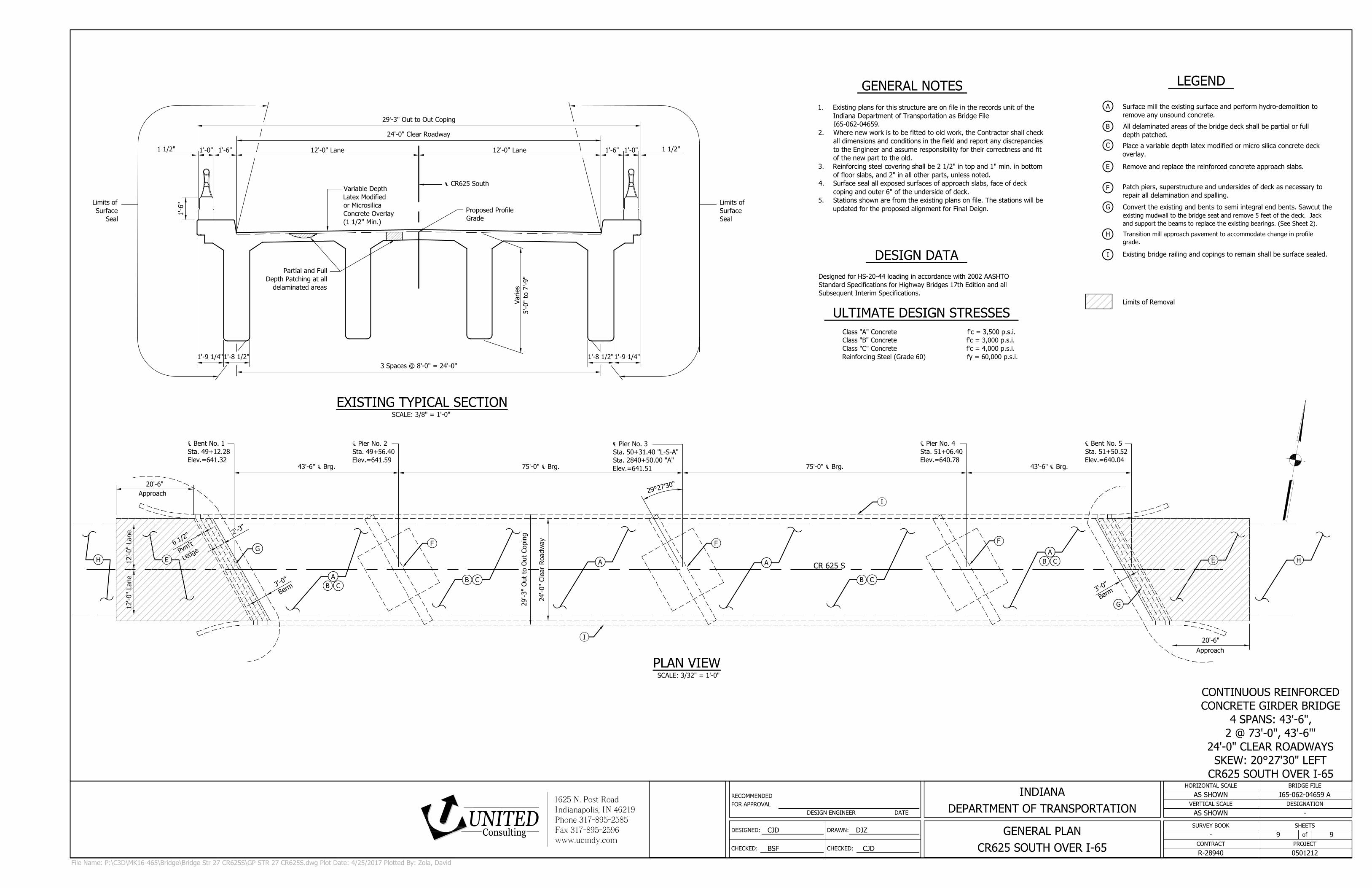
29'-3" Out to Out Coping
℄ CR625 South
24'-0" Clear Roadway
Limits of
Surface
Seal
Proposed Profile
Grade
Variable Depth
Latex Modified
or Microsilica
Concrete Overlay
(1 1/2" Min.)
12'-0" Lane 12'-0" Lane
Limits of
Surface
Seal
1 1/2"
1'-0" 1'-6"
Partial and Full
Depth Patching at all
delaminated areas
Varies
5'-0" to 7'-9"
1'-9 1/4"1'-8 1/2"
3 Spaces @ 8'-0" = 24'-0"
1'-9 1/4"1'-8 1/2"
1 1/2"
1'-0"1'-6"
1'-6"
75'-0" ℄ Brg. 75'-0" ℄ Brg.
20'-6"
Approach
43'-6" ℄ Brg. 43'-6" ℄ Brg.
Approach
20'-6"
2
9
°
2
7
'3
0
"
24'-0" Clear Roadw
ay
29'-3" O
ut to O
ut Coping
12'-0" Lane
12'-0" Lane
2
'
-
3
"
6
1
/
2
"
P
v
m
'
t
L
e
d
g
e
3
'
-
0
"
B
e
r
m
℄ Bent No. 1
Sta. 49+12.28
Elev.=641.32
℄ Pier No. 2
Sta. 49+56.40
Elev.=641.59
℄ Pier No. 3
Sta. 50+31.40 "L-S-A"
Sta. 2840+50.00 "A"
Elev.=641.51
℄ Pier No. 4
Sta. 51+06.40
Elev.=640.78
℄ Bent No. 5
Sta. 51+50.52
Elev.=640.04
A
A
A
A
CR 625 S
G
G
E
E
F
FF
B CB C
I
I
3
'
-
0
"
B
e
r
m
H
H
B C
B C
DESIGNED:
CHECKED:
DRAWN:
CHECKED:
RECOMMENDED
FOR APPROVAL
DESIGN ENGINEER DATE
SHEETS
of
VERTICAL SCALE
HORIZONTAL SCALE
CONTRACT
BRIDGE FILE
PROJECT
DESIGNATION
SURVEY BOOK
CJD DJZ
BSF CJD
AS SHOWN
AS SHOWN
I65-062-04659 A
-
-
R-28940
9 9
0501212
GENERAL PLAN
CR625 SOUTH OVER I-65
INDIANA
DEPARTMENT OF TRANSPORTATION
1625 N. Post RoadIndianapolis, IN 46219Phone 317-895-2585Fax 317-895-2596www.ucindy.com
ConsultingUNITED
SCALE: 3/8" = 1'-0"
EXISTING TYPICAL SECTION
File Name: P:\C3D\MK16-465\Bridge\Bridge Str 27 CR625S\GP STR 27 CR625S.dwg Plot Date: 4/25/2017 Plotted By: Zola, David
Limits of Removal
GENERAL NOTES
1. Existing plans for this structure are on file in the records unit of the
Indiana Department of Transportation as Bridge File
I65-062-04659.
2. Where new work is to be fitted to old work, the Contractor shall check
all dimensions and conditions in the field and report any discrepancies
to the Engineer and assume responsibility for their correctness and fit
of the new part to the old.
3. Reinforcing steel covering shall be 2 1/2" in top and 1" min. in bottom
of floor slabs, and 2" in all other parts, unless noted.
4. Surface seal all exposed surfaces of approach slabs, face of deck
coping and outer 6" of the underside of deck.
5. Stations shown are from the existing plans on file. The stations will be
updated for the proposed alignment for Final Deign.
SCALE: 3/32" = 1'-0"
PLAN VIEW
Surface mill the existing surface and perform hydro-demolition to
remove any unsound concrete.
All delaminated areas of the bridge deck shall be partial or full
depth patched.
Place a variable depth latex modified or micro silica concrete deck
overlay.
Remove and replace the reinforced concrete approach slabs.
Existing bridge railing and copings to remain shall be surface sealed.
Patch piers, superstructure and undersides of deck as necessary to
repair all delamination and spalling.
Convert the existing and bents to semi integral end bents. Sawcut the
existing mudwall to the bridge seat and remove 5 feet of the deck. Jack
and support the beams to replace the existing bearings. (See Sheet 2).
Transition mill approach pavement to accommodate change in profile
grade.
LEGEND
A
B
C
E
F
G
H
I
DESIGN DATA
Designed for HS-20-44 loading in accordance with 2002 AASHTO
Standard Specifications for Highway Bridges 17th Edition and all
Subsequent Interim Specifications.
ULTIMATE DESIGN STRESSES
Class "A" Concrete f'c = 3,500 p.s.i.
Class "B" Concrete f'c = 3,000 p.s.i.
Class "C" Concrete f'c = 4,000 p.s.i.
Reinforcing Steel (Grade 60) fy = 60,000 p.s.i.
CONTINUOUS REINFORCED
CONCRETE GIRDER BRIDGE
4 SPANS: 43'-6",
2 @ 73'-0", 43'-6"'
24'-0" CLEAR ROADWAYS
SKEW: 20°27'30" LEFT
CR625 SOUTH OVER I-65