Embed Size (px)
Citation preview
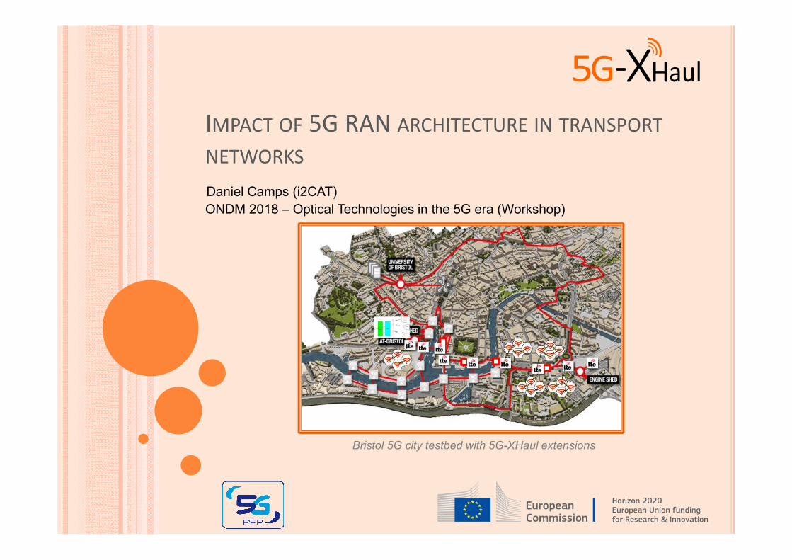
Bristol 5G city testbed with 5G-XHaul extensions
IMPACT OF 5G RAN ARCHITECTURE IN TRANSPORT
NETWORKS
Daniel Camps (i2CAT)
ONDM 2018 – Optical Technologies in the 5G era (Workshop)
OUTLINE
� From 4G to 5G architecture
� The F1 interface and new RRC states
� The F2 interface (3GPP and eCPRI)
� 5G deployment options
� 5GPICTURE’s view on a converged 5G transport
� Thoughts on transport support for 5G QoS
� Conclusions
2

FROM 4G TO 5G ARCHITECTURE
3
E-UTRAN (LTE)
eNB
(RRH-BBU)UE
X2S1-MME
S1-U
Serving
Gateway
PDN
Gateway
S5
S1
0 HSSS6
a
PCRF
Gx
PDNs
APNs
SGiU-Plane
C-Plane
EPC
MME
S11
S1-C
5GNR
gNB-CUUE
XnN2
N3
UPF UPFN9
N14AUSF
PCF
DNNs
APNs
N6U-Plane
C-Plane
5GCore
gNB-DU
F1
RRH
F2
SMF
N4AMF
N11
NSSF
N7
N1 (S-NSSAI)
N12N22
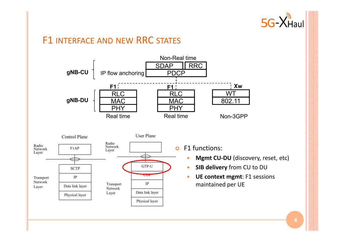
F1 INTERFACE AND NEW RRC STATES
4
� F1 functions:
� Mgmt CU-DU (discovery, reset, etc)
� SIB delivery from CU to DU
� UE context mgmt: F1 sessions
maintained per UE
Radio Network Layer
UDP
IP
Data link layer
Physical layer
Transport
Network
Layer
GTP-U
User Plane
SCTP
IP
Data link layer
F1AP
Physical layer
Radio Network Layer
Transport
Network
Layer
Control Plane
gNB-CU
gNB-DU
SDAPPDCP
RLCMACPHY
F1
Non-Real time
Real time
RRC
WT802.11
Non-3GPP
Xw
RLCMACPHY
Real time
F1
IP flow anchoring
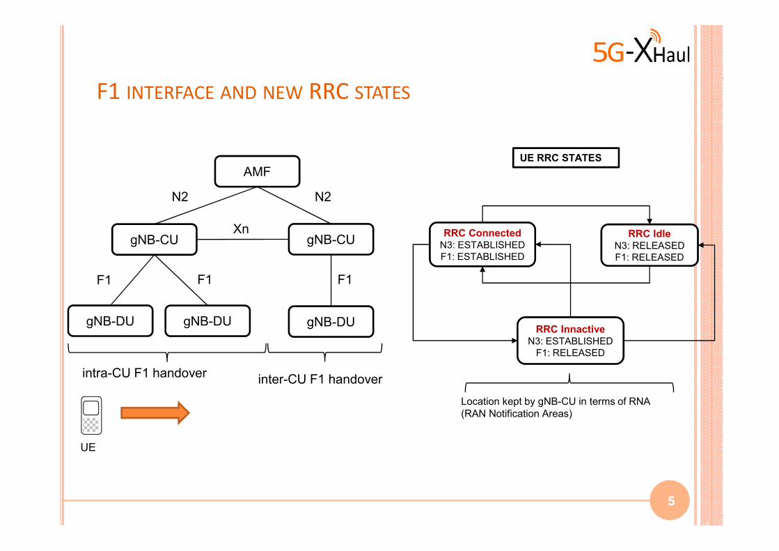
F1 INTERFACE AND NEW RRC STATES
5
gNB-CU
gNB-DU gNB-DU gNB-DU
gNB-CUXn
F1 F1 F1
UE
AMF
N2 N2
intra-CU F1 handoverinter-CU F1 handover
RRC ConnectedN3: ESTABLISHED
F1: ESTABLISHED
RRC IdleN3: RELEASED
F1: RELEASED
RRC InnactiveN3: ESTABLISHED
F1: RELEASED
UE RRC STATES
Location kept by gNB-CU in terms of RNA
(RAN Notification Areas)
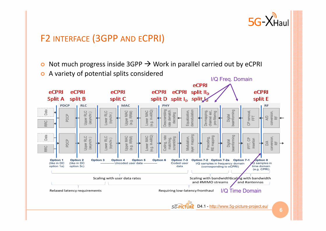
F2 INTERFACE (3GPP AND ECPRI)
� Not much progress inside 3GPP � Work in parallel carried out by eCPRI
� A variety of potential splits considered
6
I/Q Time Domain
I/Q Freq. Domain
5GPICTURE D4.1 - http://www.5g-picture-project.eu/
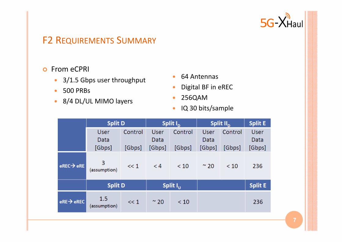
F2 REQUIREMENTS SUMMARY
� From eCPRI
� 3/1.5 Gbps user throughput
� 500 PRBs
� 8/4 DL/UL MIMO layers
7
� 64 Antennas
� Digital BF in eREC
� 256QAM
� IQ 30 bits/sample
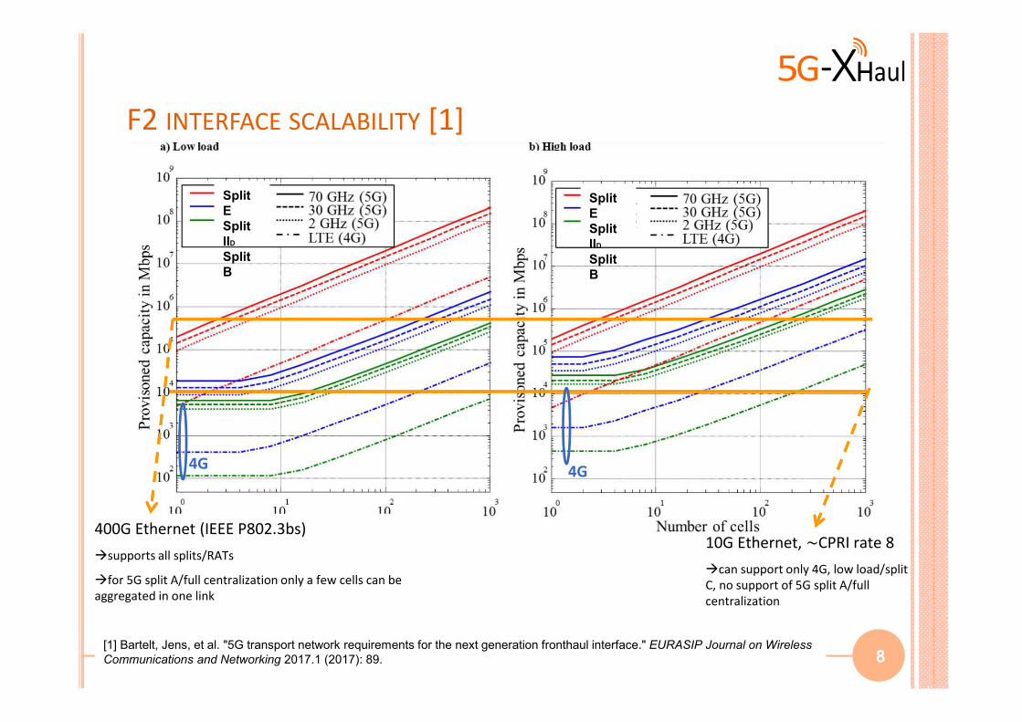
F2 INTERFACE SCALABILITY [1]
8
10G Ethernet, ~CPRI rate 8
�can support only 4G, low load/split
C, no support of 5G split A/full
centralization
400G Ethernet (IEEE P802.3bs)
�supports all splits/RATs
�for 5G split A/full centralization only a few cells can be
aggregated in one link
4G4G
Split
E
Split
IID
Split
B
Split
E
Split
IID
Split
B
[1] Bartelt, Jens, et al. "5G transport network requirements for the next generation fronthaul interface." EURASIP Journal on Wireless
Communications and Networking 2017.1 (2017): 89.
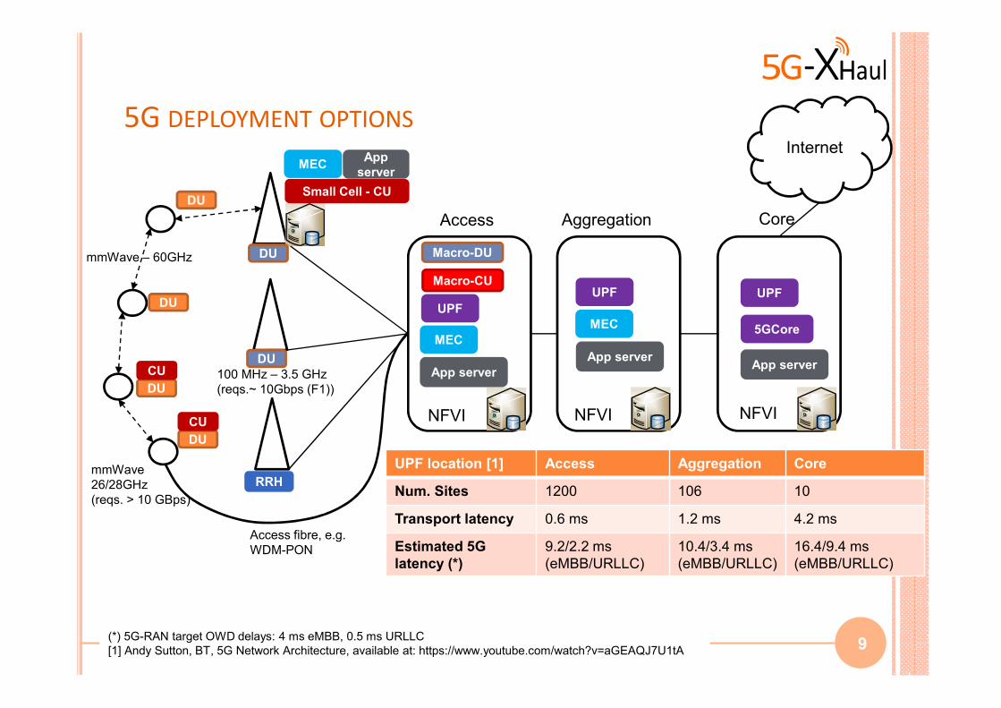
5G DEPLOYMENT OPTIONS
9(*) 5G-RAN target OWD delays: 4 ms eMBB, 0.5 ms URLLC
[1] Andy Sutton, BT, 5G Network Architecture, available at: https://www.youtube.com/watch?v=aGEAQJ7U1tA
DU
CU
DU
CU
DU
DU
Small Cell - CU
DU
DU
RRH
Macro-CUUPF
App server
App serverApp server
UPF
UPF
MEC
MEC 5GCore
App
serverMEC
Internet
mmWave – 60GHz
Aggregation CoreAccess
mmWave
26/28GHz
(reqs. > 10 GBps)
100 MHz – 3.5 GHz
(reqs.~ 10Gbps (F1))
Macro-DU
UPF location [1] Access Aggregation Core
Num. Sites 1200 106 10
Transport latency 0.6 ms 1.2 ms 4.2 ms
Estimated 5G
latency (*)
9.2/2.2 ms
(eMBB/URLLC)
10.4/3.4 ms
(eMBB/URLLC)
16.4/9.4 ms
(eMBB/URLLC)
Access fibre, e.g.
WDM-PON
NFVI NFVI NFVI
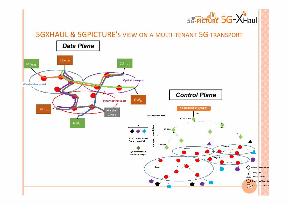
5GXHAUL & 5GPICTURE’S VIEW ON A MULTI-TENANT 5G TRANSPORT
10
Data Plane
Control Plane
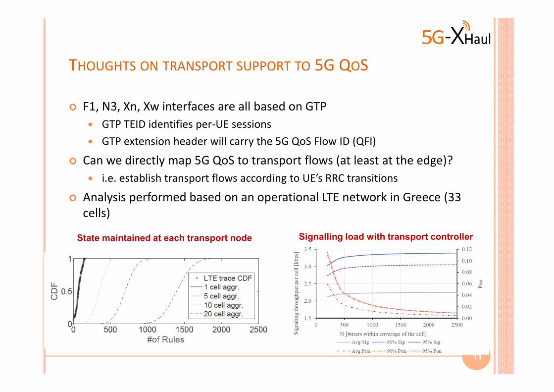
THOUGHTS ON TRANSPORT SUPPORT TO 5G QOS
� F1, N3, Xn, Xw interfaces are all based on GTP
� GTP TEID identifies per-UE sessions
� GTP extension header will carry the 5G QoS Flow ID (QFI)
� Can we directly map 5G QoS to transport flows (at least at the edge)?
� i.e. establish transport flows according to UE’s RRC transitions
� Analysis performed based on an operational LTE network in Greece (33
cells)
11
State maintained at each transport node Signalling load with transport controller
SUMMARY AND CONCLUSIONS
� 5G RAN base station decomposed into RRH – DU – CU
� “Backhaul-like” F1 interface below PDCP between CU
and DU
� Multiplicity of options (functional splits) between DU
and RRH
� 5G’s flexibility provides built-in support for low latency
applications within the network
12

Thanks for your
attention!
Questions?