Embed Size (px)
Citation preview

Copyright© 2016 by Turbomachinery Laboratory, Texas A&M Engineering Experiment Station
HYDRODYNAMIC TORQUE CONVERTERS FOR OIL & GAS COMPRESSION AND PUMPING APPLICATIONS: BASIC PRINCIPLES, PERFORMANCE CHARACTERISTICS AND APPLICATIONS
Klaus Brun, Ph.D. Program Director Southwest Research Institute San Antonio, Texas, USA Dr. Brun is the Program Director of the Machinery Program at Southwest Research Institute. His experience includes positions in engineering, project
management, and management at Solar Turbines, General Electric, and Alstom. He holds six patents, authored over 150 papers, and published two textbooks on gas turbines. Dr. Brun won an R&D 100 award in 2007 for his Semi-Active Valve invention and ASME Oil & Gas Committee Best Paper/Tutorial awards in 1998, 2000, 2005, 2009, 2010, 2012, and 2014. He was chosen to the "40 under 40" by the San Antonio Business Journal. He is the past chair of the ASME-IGTI Board of Directors and the past Chairman of the ASME Oil & Gas Applications Committee. He is also a member of the API 616 and 692 Task Forces, the Middle East and Far East Turbomachinery Symposiums, the Fan Conference Advisory Committee, and the Supercritical CO2 Conference Advisory Committee. Dr. Brun is the Executive Correspondent of Turbomachinery International Magazine and an Associate Editor of the ASME Journal of Gas Turbines for Power.
Christoph Meyenberg Head of Technical Sales Voith Turbo Crailsheim, Germany Christoph Meyenberg graduated with a Diploma of Mechanical Engineering specialized in Fluid-Dynamics from University of Hannover / Germany in 1991. Since then he has been working in
different positions as Application Engineer, Project Manager, and Sales Manager for centrifugal compressors in the process industry at MAN Diesel & Turbo. Since 2006 he is employed at Voith Turbo as Head of Technical Sales Americas for variable speed drives
Joseph Thorp Engineering Consultant Aramco Services Houston, Texas, USA Joseph M. Thorp is a machinery Consultant for Aramco Services Company. He is a past recipient of
Aramco's coveted President's Award for his work in advanced flow modeling and optimization. Mr. Thorp is Chairman Emeritus of the American Petroleum Institute's Sub-Committee on Mechanical Equipment. He has authored numerous technical papers and served as an advisory committee member of Texas A&M's International Pump User's Symposium and the Middle East Maintenance Conference. He holds a B.S. degree (Mechanical Engineering) from Michigan State University, an MBA from the University of St. Thomas and is a registered Professional Engineer in the State of Texas.
INTRODUCTION
The hydrodynamic torque converter was invented in 1905 by Herrmann Foettinger as an alternative to a regular speed changing gear for shipboard propulsion. At that time, mechanical reduction gears for such high power applications were not available. The core idea of hydrodynamic torque converters and fluid couplings is to provide wear free power transmission using a hydraulic closed pump and turbine cycle. In the following decades, hydrodynamic torque converters experienced significant improvements driven by the automotive industry, and their use spread into various applications.
Today, torque converters are commonly used in cars, busses, locomotives, construction equipment, and gas compression as a means of (i) smooth power transmission, (ii) to provide torque amplification during startup conditions, and (iii) to act as a damper for driver and driven equipment torsional disturbances and shock loads. In the oil and gas industry, torque converters are often used as integrated components in drive transmissions for electric motor driven compressors or pumps trains. They provide step-less speed variation along with progressive torque increase towards low speed. For example, torque converters and hydraulic couplings can be used to drive a variable speed centrifugal compressor using a fixed speed electric motor without the need for a variable frequency drive. In recent years, torque converters in combination with planetary gearboxes have been successfully demonstrated as a viable technology for variable speed electric motor driven centrifugal compressor applications. Torque converters are also used as soft starters between generators and gas or steam turbines. The unique power transmission features of the torque converter make it an option for equipment that requires start-up torque assistance and speed control. Modern torque converters up to 65,000 kW have been designed and are widely in operation.
The goal of this short course tutorial is to provide a basic understanding of the function of hydrodynamic couplings and

Copyright© 2016 by Turbomachinery Laboratory, Texas A&M Engineering Experiment Station
torque converters, the physics of the hydrodynamic circuits, the influence on the performance characteristic of the three active main components (pump, turbine, and stator), and the application of the torque converter for startup assist and speed control. The function and basic fluid mechanics of hydrodynamic torque transmission will be discussed. Design options, sizing, and function will be briefly explained using simplified examples. The possibility for the use of a torque converter embedded in a gear assembly is presented along with an overview of its special features, function, and application.
This presentation aims to provide basic understanding of the function and operating principles of hydrodynamic transmission and torque converters. Fundamental performance parameters, governing equations, characteristic operational curves, and basic application requirements in the oil and gas industry are also discussed. To cover this broad range of subjects, the text is divided into the following sub-topics
1. Transmitting torque and force 2. Torque characteristics 3. Hydrodynamic transmission 4. Torque converter 5. Performance maps and control 6. Torque converter integrated with gearbox application
Each of these topics is discussed at a high level to provide the reader with sufficient information to properly apply this technology in industrial applications. A case study of the application of torque converters in an oil & gas facility is also included.
TRANSMITTING TORQUE AND FORCE
In turbomachinery applications, a driver such as an electric motor, a gas turbine, or a steam turbine transmits torque to drive machinery such as a compressor, a pump, or a generator. Specifically, the driver provides the power and the driven equipment the load. When matching drivers and driven equipment for an application, it is critically important to understand this force transmission process.
The two examples in Figure 1 and Figure 2 provide examples of simple torque transmission application. Figure 1 shows a crane with a loading arm driven by an electric motor. In this case, the torque on the motor is the loading arm length, x, multiplied by the weight of the load, F. The torque, M (or normalized torque M/MN) can be plotted versus various parameters of interest, such as lifting position, speed, or acceleration. The motor drives the arm directly, not the pulley. Here the plot shows the characteristic curve (required load torque) of normalized torque versus lifting speed. One should note that this characteristic curve is a constant since the loading torque is not dependent on lifting speed. Specifically,
it does not matter if the load is lifted fast or slow, the load torque is the same. However, the plot in Figure 1 also shows the available motor torque, which is clearly a function of speed. The faster the motor spins, the less torque it can provide. When overlaying the required versus available torque curves, one can easily determine the limiting lifting speed: The speed at which the available motor torque is equal to that of the required load torque. Above this speed, the motor cannot provide sufficient torque and would not be able to lift the load. Below this limit, the driver torque exceeds the load torque, and the lifting process would accelerate until the limit speed is reached.
This is the simplest form of a torque characteristic curve for driver and driven equipment. Depending on the application, available and required torque can vary with position, speed, and acceleration.
FIGURE 1: EXAMPLE OF TORQUE TRANSMISSION
FIGURE 2: DRIVER AND DRIVEN EQUIPMENT
Figure 2 shows a slightly more complex form of available versus required torque characteristic curves. Here a tractor’s pulling force is plotted versus normalized tractor speed with increasing load lines. The load lines represent a combination of drag, friction, and gravitational forces. Because of the
Copyright© 2016 by Turbomachinery Laboratory, Texas A&M Engineering Experiment Station
nature of drag force (1/2 ρ v2 cD), the required force curves are seen to be quadratic in shape. For example, at a small load (or low incline), the bottom curve represents the lowest load line. This load line intersects with the available engine force line at a normalized speed of unity which represents the limit of highest normalized speed the tractor could travel for the specified load and engine force lines. If the tractor transports a large load or experiences more drag, then a higher load line would apply, and the resulting maximum speed limit would be reduced as shown in the figure. Clearly, this is an oversimplification, since the load line should not be simple line but a complex function of all forces (drag, gravity, friction) it represents. Similarly, the available engine force is impacted by all engine and transmission operating settings such as gear, fuel-to-air mixture ratio, air density, etc. Nonetheless, this simplified curve provides a basic tool that allows overall estimation of how fast a tractor could travel for a given engine power available and load condition.
Thus, for matched combinations of driver and driven equipment, the overlap of the driven load versus available driver force, torque, or power curves can be utilized to determine the operating limits of speed and acceleration (and position for same cases) of the rigidly shaft or gear coupled equipment. This is always the case for any hard coupled driver and driven machinery. For soft coupled equipment, in cases where a hydraulic coupling or torque converter is utilized between the driver and driven equipment, the operating limits are less restraint but the analysis becomes more complex. This will be discussed in significant detail below.
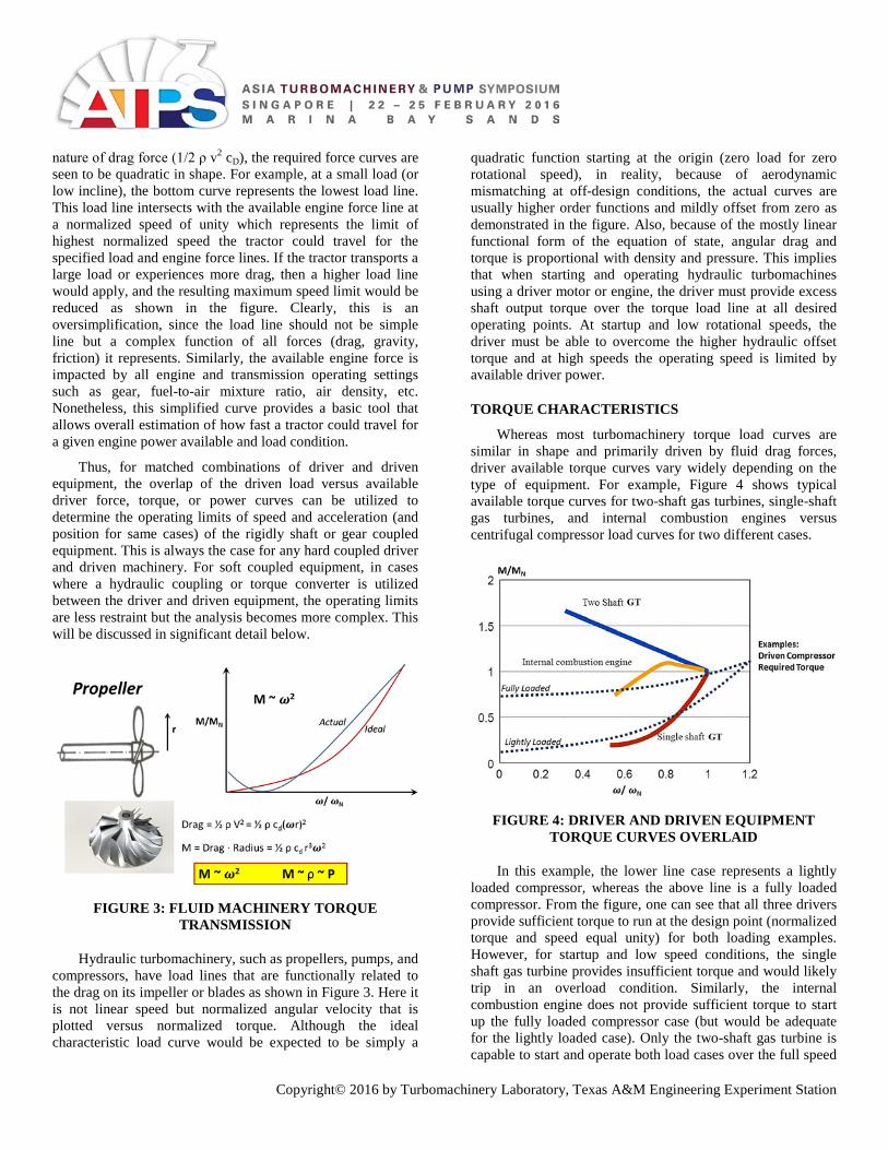
FIGURE 3: FLUID MACHINERY TORQUE
TRANSMISSION
Hydraulic turbomachinery, such as propellers, pumps, and compressors, have load lines that are functionally related to the drag on its impeller or blades as shown in Figure 3. Here it is not linear speed but normalized angular velocity that is plotted versus normalized torque. Although the ideal characteristic load curve would be expected to be simply a
quadratic function starting at the origin (zero load for zero rotational speed), in reality, because of aerodynamic mismatching at off-design conditions, the actual curves are usually higher order functions and mildly offset from zero as demonstrated in the figure. Also, because of the mostly linear functional form of the equation of state, angular drag and torque is proportional with density and pressure. This implies that when starting and operating hydraulic turbomachines using a driver motor or engine, the driver must provide excess shaft output torque over the torque load line at all desired operating points. At startup and low rotational speeds, the driver must be able to overcome the higher hydraulic offset torque and at high speeds the operating speed is limited by available driver power.
TORQUE CHARACTERISTICS
Whereas most turbomachinery torque load curves are similar in shape and primarily driven by fluid drag forces, driver available torque curves vary widely depending on the type of equipment. For example, Figure 4 shows typical available torque curves for two-shaft gas turbines, single-shaft gas turbines, and internal combustion engines versus centrifugal compressor load curves for two different cases.
FIGURE 4: DRIVER AND DRIVEN EQUIPMENT
TORQUE CURVES OVERLAID
In this example, the lower line case represents a lightly loaded compressor, whereas the above line is a fully loaded compressor. From the figure, one can see that all three drivers provide sufficient torque to run at the design point (normalized torque and speed equal unity) for both loading examples. However, for startup and low speed conditions, the single shaft gas turbine provides insufficient torque and would likely trip in an overload condition. Similarly, the internal combustion engine does not provide sufficient torque to start up the fully loaded compressor case (but would be adequate for the lightly loaded case). Only the two-shaft gas turbine is capable to start and operate both load cases over the full speed
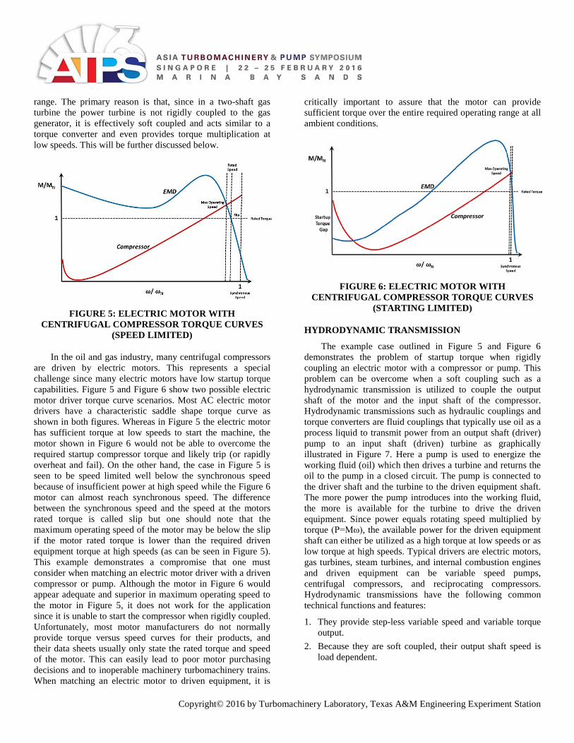
Copyright© 2016 by Turbomachinery Laboratory, Texas A&M Engineering Experiment Station
range. The primary reason is that, since in a two-shaft gas turbine the power turbine is not rigidly coupled to the gas generator, it is effectively soft coupled and acts similar to a torque converter and even provides torque multiplication at low speeds. This will be further discussed below.
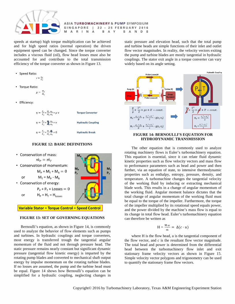
FIGURE 5: ELECTRIC MOTOR WITH
CENTRIFUGAL COMPRESSOR TORQUE CURVES (SPEED LIMITED)
In the oil and gas industry, many centrifugal compressors are driven by electric motors. This represents a special challenge since many electric motors have low startup torque capabilities. Figure 5 and Figure 6 show two possible electric motor driver torque curve scenarios. Most AC electric motor drivers have a characteristic saddle shape torque curve as shown in both figures. Whereas in Figure 5 the electric motor has sufficient torque at low speeds to start the machine, the motor shown in Figure 6 would not be able to overcome the required startup compressor torque and likely trip (or rapidly overheat and fail). On the other hand, the case in Figure 5 is seen to be speed limited well below the synchronous speed because of insufficient power at high speed while the Figure 6 motor can almost reach synchronous speed. The difference between the synchronous speed and the speed at the motors rated torque is called slip but one should note that the maximum operating speed of the motor may be below the slip if the motor rated torque is lower than the required driven equipment torque at high speeds (as can be seen in Figure 5). This example demonstrates a compromise that one must consider when matching an electric motor driver with a driven compressor or pump. Although the motor in Figure 6 would appear adequate and superior in maximum operating speed to the motor in Figure 5, it does not work for the application since it is unable to start the compressor when rigidly coupled. Unfortunately, most motor manufacturers do not normally provide torque versus speed curves for their products, and their data sheets usually only state the rated torque and speed of the motor. This can easily lead to poor motor purchasing decisions and to inoperable machinery turbomachinery trains. When matching an electric motor to driven equipment, it is
critically important to assure that the motor can provide sufficient torque over the entire required operating range at all ambient conditions.
FIGURE 6: ELECTRIC MOTOR WITH
CENTRIFUGAL COMPRESSOR TORQUE CURVES (STARTING LIMITED)
HYDRODYNAMIC TRANSMISSION
The example case outlined in Figure 5 and Figure 6 demonstrates the problem of startup torque when rigidly coupling an electric motor with a compressor or pump. This problem can be overcome when a soft coupling such as a hydrodynamic transmission is utilized to couple the output shaft of the motor and the input shaft of the compressor. Hydrodynamic transmissions such as hydraulic couplings and torque converters are fluid couplings that typically use oil as a process liquid to transmit power from an output shaft (driver) pump to an input shaft (driven) turbine as graphically illustrated in Figure 7. Here a pump is used to energize the working fluid (oil) which then drives a turbine and returns the oil to the pump in a closed circuit. The pump is connected to the driver shaft and the turbine to the driven equipment shaft. The more power the pump introduces into the working fluid, the more is available for the turbine to drive the driven equipment. Since power equals rotating speed multiplied by torque (P=Mω), the available power for the driven equipment shaft can either be utilized as a high torque at low speeds or as low torque at high speeds. Typical drivers are electric motors, gas turbines, steam turbines, and internal combustion engines and driven equipment can be variable speed pumps, centrifugal compressors, and reciprocating compressors. Hydrodynamic transmissions have the following common technical functions and features:
1. They provide step-less variable speed and variable torque output.
2. Because they are soft coupled, their output shaft speed is load dependent.

Copyright© 2016 by Turbomachinery Laboratory, Texas A&M Engineering Experiment Station
3. Torque amplification at low speeds is possible since, for a given available hydraulic power from the pump, the turbine can exchange torque for speed.
4. Speed amplification or reduction is possible based on the selection of the pump and turbine performance characteristics.
5. Torsional vibrations between the driver and driven equipment are decoupled.
6. Because there is no hard interface between the output and input shaft (clutch), there is no direct mechanical wear.
FIGURE 7: BASIC FUNCTION OF HYDRODYNAMIC
TRANSMISSION
FIGURE 8: FLUID TRANSMISSION FOR HIGH
TORQUE LOADS AT STARTUP
Figure 8 illustrates how a hydrodynamic transmission can overcome a high startup torque scenario. Both the pump available and the turbine load torque curves are shown. Clearly for a fixed load, if the curves are directly overlaid, the pump (providing little torque) would not be able to drive the turbine (which requires a very high torque at low speeds). So how can this work? The answer is that the pump and turbine are not rigidly coupled and, therefore, their speeds do not have
to be equal. When trying to start the driven equipment, the pump can rotate at a very high speed and produce sufficient power for the required high torque at low speeds of the turbine and driven equipment. This is illustrated by the dotted arrows in the graph of Figure 8. Specifically, for the torque required by the turbine, MT, at low turbine speed, ωT, the pump produces sufficient torque (MP≥MT) at a high pump speed ωP. Additionally the curves demonstrate that the driven equipment could operate over its full speed range from ω/ωN=0 to ω/ωN=1 since the pump power (and torque) will exceed required turbine hydraulic power (and torque) for all conditions. The hydrodynamic transmission allows for variable speed and torque output which is only limited by its input shaft power and internal fluid losses.
It is important to recognize that hydrodynamic transmission is fundamentally different than other types of power transmissions as shown in Figure 9. Rigidly coupled transmissions such as a belt-drive or a gearbox have fixed speed and torque ratios. Similarly a hydrostatic drive utilizes positive displacement pumps and turbines and effectively acts like a rigid transmission. Only hydrodynamic transmissions allow for slip between the input and output shafts and can provide varying speed and torque ratio power transmission. However, because of internal fluid dynamic losses, hydrodynamic transmissions tend to have a lower transmission efficiency 𝜂𝜂 (= Power Out / Power In) than rigidly coupled transmissions.
FIGURE 9: TYPES OF TRANSMISSIONS
Although Figure 7 illustrates a hydrodynamic transmission, actual hydraulic couplings and torque converter arrangements and geometries must be more compact and rugged. Figure 10 shows a typical hydrodynamic coupling with a mixed radial flow pump driving a mixed radial flow turbine. Here the fluid enters the pump axially and is redirected toward the outward radial direction by the rotating

Copyright© 2016 by Turbomachinery Laboratory, Texas A&M Engineering Experiment Station
blades which impart tangential momentum and thus flow head to the circulating fluid. The high flow head fluid then enters the turbine in the axial direction and is turned toward the inward radial direction and then circulates back into the pump in the axial direction. The turbine converts the flow head which is mostly in the form of angular momentum into mechanical rotation of the turbine to drive the output shaft. The hydraulic coupling thus consists, as a minimum, of two flow components: A pump and a turbine. Torque converters also utilize a stator. Some of the more complex torque converter designs contain multiple pumps, turbines, and stators to achieve a desired performance characteristic as will be discussed below.
FIGURE 10: TYPICAL HYDRODYNAMIC COUPLING
ARRANGEMENT
Basic Types of Hydrodynamic Transmissions
Many arrangements of hydrodynamic couplings are possible but the fundamental three types are hydraulic couplings (pump and turbine), torque converter (pump, turbine, and stator), and hydraulic breaks (pump and static turbine wheel) as shown in Figure 11. However, hydraulic breaks are technically speaking not transmission devices and are not commonly used in the oil and gas industry, so they are not further discussed herein.
One should note that a simple hydraulic coupling with one pump and one stator has limited torque transmission flexibility when compared to a torque converter. In the hydraulic coupling, since there are only two flow elements (pump and turbine), their torque must be equal and opposite (Newton’s First Law: ΣM=0). Specifically, the pump torque must equal the turbine torque for all pump and turbine operating speeds (MP=MT). Because in a hydraulic coupling, the fluid torque transmission is almost completely via angular momentum exchange from the pump to the turbine, this also implies that the turbine speed can only be equal or smaller than the pump speed. Thus, hydraulic transmissions can be utilized for speed reduction regulation in variable speed applications, but they do not provide torque amplification at startup or speed increasing regulation. This feature can also
be used as a physical speed limiting mechanism since in hydraulic couplings overspeeding the driven equipment is impossible. On the other hand, torque converters have a third element, a non-rotating stator (sometimes called reactor) that redirects the flow angle between the pump and the turbine, thus changing the angular momentum of the circulating fluid to add or absorb torque (but not power). Torque converters can be utilized for startup torque amplification as well as driven equipment speed increase and decrease applications.
FIGURE 11: TYPES OF HYDRODYNAMIC
TRANSMISSIONS
Governing Equations
Fundamentally a hydraulic coupling and torque converter operates like a pump and turbine in a closed loop arrangement. All conventional pump and turbine flow transport equations, such as Bernoulli’s and Euler’s turbomachinery equations, are applicable. Additionally, conservation equations such as mass, momentum, and energy balances are similarly applicable for the closed system. For convenience reasons, a number of standard definitions for speed ratio (ν), torque ratio (μ), and efficiency (η) are commonly used when discussing hydrodynamic transmission. These are shown in Figure 12.
Figure 12 also demonstrates that the efficiency for a hydraulic break is always zero, for a hydraulic coupling is equal to the speed ratio, and for a torque converter is equal to the speed ratio multiplied by the torque ratio.
The conservation equations (mass, moment, and energy) for a torque converter are shown in Figure 13. As previously discussed, the sum of torque contribution in the torque converter must include not just the pump and turbine but also the stator and, thus, positive and negative torque modulation is possible. In most industrial torque converters, the stator angle can be mechanically varied such that the output torque and, for a given shaft load, the output speed can be altered. The stator effectively changes the flow incidence angle into the pump by redirecting the meridional recirculating flow. That is, using the variable angle stator, for low speed ratios (low output shaft
Copyright© 2016 by Turbomachinery Laboratory, Texas A&M Engineering Experiment Station
speeds at startup) high torque multiplication can be achieved and for high speed ratios (normal operation) the driven equipment speed can be changed. Since the torque converter includes a viscous fluid (oil), flow head losses must also be accounted for and contribute to the total transmission efficiency of the torque converter as shown in Figure 13.
FIGURE 12: BASIC DEFINITIONS
FIGURE 13: SET OF GOVERNING EQUATIONS
Bernoulli’s equation, as shown in Figure 14, is commonly used to analyze the behavior of flow elements such as pumps and turbines. In hydraulic couplings and torque converters, most energy is transferred trough the tangential angular momentum of the fluid and not through pressure head. The static pressure remains nearly constant but significant dynamic pressure (tangential flow kinetic energy) is imparted by the rotating pump blades and converted to mechanical shaft output energy by impulse momentum on the rotating turbine blades. If no losses are assumed, the pump and the turbine head must be equal. Figure 14 shows how Bernoulli’s equation can be simplified for a hydraulic coupling, neglecting changes in
static pressure and elevation head, such that the total pump and turbine heads are simple functions of their inlet and outlet flow vector magnitudes. In reality, the velocity vectors exiting the pump and turbine blades are mostly tangential in hydraulic couplings. The stator exit angle in a torque converter can vary widely based on its angle setting.
FIGURE 14: BERNOULLI’S EQUATION FOR
HYDRODYNAMIC TRANSMISSION
The other equation that is commonly used to analyze rotating machinery flows is Euler’s turbomachinery equation. This equation is essential, since it can relate fluid dynamic kinetic properties such as flow velocity vectors and mass flow to performance parameters such as head and power and then further, via an equation of state, to intensive thermodynamic properties such as enthalpy, entropy, pressure, density, and temperature. A turbomachine changes the tangential velocity of the working fluid by inducing or extracting mechanical blade work. This results in a change of angular momentum of the working fluid. Angular moment balance dictates that the total change of angular momentum of the working fluid must be equal to the torque of the impeller. Furthermore, the torque of the impeller multiplied by its rotational speed equals power, and the power divided by the machine’s mass flow is equal to its change in total flow head. Euler’s turbomachinery equation can therefore be written as
H = M 𝜔𝜔
𝑚𝑚 ̇= Δ(𝑐𝑐 · 𝑢𝑢)
where H is the flow head, u is the tangential component of the flow vector, and c is the resultant flow vector magnitude. The total head and power is determined from the differential head between the turbomachinery flow inlet and exit stationary frame velocity vectors as shown in Figure 15. Simple velocity vector polygons and trigonometry can be used to quantify the stationary frame flow vectors.

Copyright© 2016 by Turbomachinery Laboratory, Texas A&M Engineering Experiment Station
FIGURE 15: EULER’S TURBOMACHINERY
EQUATION
Combining Bernoulli’s and Euler’s turbomachinery equation (and after some algebra) one can show:
)(
)(2
)(
21
22
22
21
22
22
12
2
rrH
HHH
rrVVH
LossesTp
LossesTP
−≈−⇒
=+
−≈−
=
ωω
ω
This indicates that the head loss and thus the hydraulic coupling’s efficiency is a strong function of the difference between the pump and turbine speed. To qualify this, we can divide the hydraulic coupling’s operating range into three regimes:
Startup 𝜔𝜔P >>> 𝜔𝜔T High head losses due to fluid shear
Acceleration 𝜔𝜔P > 𝜔𝜔T Moderate losses due to fluid shear
Normal Operation 𝜔𝜔P ~ 𝜔𝜔T Small losses due to fluid shear
Clearly, a hydrodynamic transmission will provide the best performance when its pump and turbine speeds are similar during normal operation and its lowest efficiency during startup conditions.
TORQUE CONVERTER
In the previous sections, we discussed hydrodynamic torque transmission, its basic function, and the governing equations to analyze the closed circuit oil loop. This section primarily focusses on torque converters, since they are typically used, in combination with epicyclical gears, for electric motor driven centrifugal compressor applications in oil and gas applications. The torque converter has one or
multiple pumps, turbines, and stators and provides smooth power transmission from a driver to driven equipment. As previously mentioned, the torque converter can be used for driven equipment speed control with variable guide vane (stator or reactor) and for startup applications it provides torque amplification at low speeds. Torque converters also dampen torsional vibrations between driver and driven equipment. Torque multiplication is achieved by a simple balance of torque between its flow components, specifically:
Torque Multiplication: MT = MP + MR MT ≠ MP
History
The modern torque converter was invented by Hermann Foettinger at Vulcan Shipyards in Hamburg, Germany, in 1905 (Figure 16). At the time, gearboxes and belt drives for speed reducing power transmission applications were design limited to below 100 Hp. Foettinger required a torque converter for shipboard propulsion speed reduction power transmission from a steam turbine to a propeller shaft. His driver was a 100 Hp steam turbine operating at 1,000 rpm, and his torque converter achieved 4:1 speed reduction at an efficiency of 82%. Since the 1940s, the torque converter has been widely utilized for automotive applications. Later on in the 1960s, torque converters were started to be used for turbomachinery power transmission applications and other industrial services. Today, thousands of torque converters are used in industry with the largest units operating in power transmission applications up to 100,000 Hp.
FIGURE 16: H. FOETTINGER AND HIS TORQUE
CONVERTER INVENTIONS
Torque Converter Function
As an example of a common type of torque converter, Figure 17 shows a conventional automotive Tri-Lok torque converter design and basic performance curves of speed ratio versus torque ratio and efficiency. At low speed ratios, where the differential between the pump and turbine speeds is the highest, the torque converter exhibits low efficiency but high torque multiplication. That is, the fast spinning engine is able to overcome the high startup torque required when the vehicle is not yet moving. As the speed ratio increases, the efficiency is seen to increase, and the torque multiplication decreases. For this particular torque converter design, the efficiency peaks at a speed ratio of approximately 80% and would

Copyright© 2016 by Turbomachinery Laboratory, Texas A&M Engineering Experiment Station
decrease if the speed ratio further increases. This is primarily a characteristic of the hydraulic design and torque converters with peak efficiencies at higher or lower speed ratios can be designed for specific application requirements.
FIGURE 17: AUTOMOTIVE TORQUE CONVERTER
EXAMPLE
In this particular case, the torque converter has an added feature that allows it to unlock the stator at approximately 80% speed ratio so that the stator can float freely and spin. This effectively converts the torque converter into a hydraulic coupling at high speed ratios, since there is no reaction torque, and the pump and turbine torque must be equal. The effect is that at speed ratios above 80%, the automotive torque converter performance curve‘s efficiency increases linearly with speed ratio and torque ratio becomes unity. Most automotive torque converters also have a built-in clutch that rigidly couples the input to the output shafts when the speed ratio reaches unity. Clearly, the characteristic performance curves of speed ratio versus torque ratio versus efficiency allows one to determine the required engine power for all operating speeds and required loads of the torque converter.
Arrangements
Many pump, turbine, and stator arrangements within a torque converter are possible to achieve a desired torque versus speed ratio and efficiency characteristic. Figure 18 shows the three most common types of torque converter: The Tri-Lok which is used exclusively in the automotive industry and the Foettinger and DIWA types, which are both common in power transmission and industrial applications. Torque converters are functionally different than hydraulic couplings in that they incorporate a stator element, and in most industrial applications that stator angle can be varied for speed and torque control. The different arrangement of pump, stator, and
turbine achieves results in different performance curves, which will be further discussed below.
FIGURE 18: TYPICAL TORQUE CONVERTER
ARRANGEMENTS
PERFORMANCE MAPS AND CONTROL
To utilize a torque converter for an electric motor driven centrifugal compressor application, its performance curves and parameters must be defined. The most basic forms of characteristic curves are generated by simply plotting required input speed versus output torque and power. However, this curve has limited practical application, since it only works for a single output speed and input power torque operating point. Many other one-parameter curves can be generated, but they lack generality and are usually not useful. Non-dimensional parameter curves are generally more practical. For example, the previously discussed speed ratio versus torque ratio and efficiency curve is a more generic, non-dimensional type of curve. Unfortunately, this curve is not scalable to different sizes of torque converters, since torque ratio does not contain size and speed similarity parameters. A more universal scalable non-dimensional parameter for torque and power is required.
Characteristic Parameters
To derive at an appropriate non-dimensional scalable parameter for any turbomachine, one usually starts with the fan and geometrical similarity laws. For pumps, turbines, and therefore, torque converters, the fan law relations are shown in Figure 19 for mass flow, head, and power versus impeller diameter and speed. For example, head increase with rotational speed squared while power increases with rotational speed cubed. Figure 19 also shows that velocity vector polygons are a similarity parameter and linearly scale with diameter. Specifically, the tangential, radial, and total resultant vector magnitudes are directly proportional to the diameter of the impeller. This also implies that the mass flow of the machine must increase with the diameter cubed since the though-flow velocity and the two length directions for through-flow area are all linear with diameter.

Copyright© 2016 by Turbomachinery Laboratory, Texas A&M Engineering Experiment Station
FIGURE 19: TURBOMACHINERY SIMILARITY
LAWS
FIGURE 20: HYDRODYNAMIC POWER AND
TORQUE PERFORMANCE CHARACTERISTIC PARAMETER
Since power is mass flow multiplied by head difference, and therefore, proportional to density (ρ), diameter (D) to the fifth power, and rotational speed (ω) to the third power, one can derive a simple proportionality relationship for power as shown in Figure 20. A non-dimensional parameter, λ, can then be defined that relates the turbomachine’s hydraulic power or torque to the diameter, density, and rotational speed of the impeller. λ is a scalable non-dimensional characteristic parameter that is useful when analyzing torque converter performance.
Torque Converter Performance Maps
Figure 21 shows two examples of the characteristic performance parameter versus speed ratio. Since their pump, turbine, and stator arrangements are drastically different, the Tri-Lok torque and Foettinger torque converters performance curves vary significantly. So how can these curves be utilized to determine the required driver power at a given operating speed?
FIGURE 21: CHARACTERISTIC PERFORMANCE
MAPS
1. The driven equipment (e.g., centrifugal compressor) requires a certain speed and power (or torque) to achieve its desired operating point. This defines: MT ωT
2. One also usually knows the speed of the driver (e.g., electric motor):
ωP 3. thus, we can calculate speed ratio:
𝜈𝜈 4. From the torque converter performance maps we can now
look up the non-dimensional input power parameter: λ

Copyright© 2016 by Turbomachinery Laboratory, Texas A&M Engineering Experiment Station
5. From the definition of λ and the torque converter dimensions, we can calculate required input (motor) power: PP
Thus, given the required driven equipment conditions and available driver performance, a properly sized torque converter can be defined. This approach can also be used to determine if the driver provides adequate power over the entire operating speed range of the driven equipment and torque converter.
The Foettinger torque converter and hydraulic coupling characteristic performance curves are examined in more detail in Figure 22 through Figure 25. Figure 22 and Figure 23 show torque ratio (μ), efficiency (η), and non-dimensional characteristic torque (λ) versus speed ratio (ν). High torque multiplication at low speed ratios, flat input power over the full speed range, and efficiency drops at very high and low speed ratios can be observed. These operating characteristics translate to the operating regimes shown in Figure 23. Specifically at low speed ratios, the torque converter provides the necessary torque amplification required to start the driven equipment. In the midrange, the torque converter is at its highest efficiency, best for variable speed and speed reducing normal operation. At high speed ratios, the torque converter can be disabled by clutching the input and output shafts, thus providing a rigid coupling and no loss operation. Foettinger torque converters are well suited for variable speed centrifugal compressor applications using fixed speed electric motors.
FIGURE 22: FOETTINGER TORQUE CONVERTER
PERFORMANCE MAPS
FIGURE 23: TORQUE CONVERTER OPERATING
RANGES
Similar characteristic performance curves are shown for a hydraulic coupling in Figure 24. A flat torque curve (input equals output torque), input power drops at high speed ratios, and low efficiency at low speed ratio but excellent efficiencies at high speed ratios can be seen. Thus, the hydraulic coupling does not provide torque amplification at low speed ratios. It is best suited for applications where soft power coupling is required, but the input and output shaft speeds are similar such as electric motor driven multi-stage pumps.
Torque Converter Control
Since the torque converter is a soft fluid transmission, the shaft output speed and available power is primarily controlled by the torque converter’s shaft input speed and power. The output control behavior will simply follow the previously discussed characteristic performance curves. However, several other control methods can be used to adjust the torque converter’s performance. Figure 25 shows three standard methods:
FIGURE 24: HYDRODYNAMIC COUPLING
PERFORMANCE MAP

Copyright© 2016 by Turbomachinery Laboratory, Texas A&M Engineering Experiment Station
FIGURE 25: DIRECT CONTROL METHODS FOR
TORQUE CONVERTER
• Throttling the flow between the pump and turbine: This reduces the head available to the turbine (by increasing the flow losses) and shifts the non-dimensional torque curve downward. By reducing the available head to the turbine, the speed of the driven equipment is reduced if the required load is unchanged.
• Changing the stator angle: This alters the incidence angles between pump and turbine and thus, the angular momentum of the fluid. The angular momentum that is transferred to the turbine is either increased or decreased, and thus, the output shaft torque and speed can be regulated.
• Draining the torque converter fluid to a specified partial fill level: The effect of this is similar to throttling the circulating fluid in that it reduces the total head and power that is transferred from the pump to the turbine. However, rather than shifting the normalized torque parameter downward, the torque converter acts as if it was dimensionally scaled. The net effect is that output speed decreases with fill level for a required load.
Two other other control methods that are sometimes used in torque converters are to: • Free float the stator: By disengaging the stator so that it
can spin with the rotating fluid, the torque converter effectively becomes a hydraulic coupling. Once this occurs, the characteristic performance curves are those of a hydraulic coupling with high efficiencies at high speed ratios and a torque ratio of unity. This control method is commonly used in automotive torque converters as shown in Figure 17. However, this method is mechanically difficult to implement in Foettinger torque converters with variable angle stators.
• Clutch the pump and turbine: At very high speed ratios when the turbine speed nears that of the pump, it is often better to rigidly clutch the driver and driven equipment shafts and entirely by-pass the torque converter. In some torque converter models, this is accomplished by completely draining the torque converter. The result is a power transfer from a soft to a hard transmission. All
automotive torque converters and some industrial torque converters utilize this control method.
TORQUE CONVERTER INTEGRATED WITH GEARBOX APPLICATION
For oil and gas applications where a fixed speed asynchronous (induction) electric motor drives a centrifugal compressor, a combination torque converter for speed control and a gearbox for speed increase are viable technology options. Most AC asynchronous (induction) electric motors operate at 50 Hz (1,500 rpm or 3,000 rpm) or 60 Hz (1,800 pm or 3,600 rpm), which is well below the speed most centrifugal compressors require (above 8,000 rpm). In this case, the gearbox provides a speed increase ratio of 2 or 3, while the torque converter or hydraulic coupling allows for speed control down to approximately 50% maximum continuous speed. Figure 26 shows a simplified process diagram for this type of arrangement with a parallel gearbox and hydraulic coupling.
FIGURE 26: ELECTRIC MOTOR DRIVEN
CENTRIFUGAL COMPRESSOR WITH HYDRAULIC COUPLING AND PARALLEL GEARBOX.
Rather than operating the torque converter and gearbox in series, as shown in Figure 26 the torque converter can also be integrated to operate in parallel with the gearbox. In this arrangement, as shown in Figure 27, the majority of the power is directly transmitted through the gearbox with very low losses while a small fraction of the power (<25%) is transmitted through a torque converter to allow for some speed control. Figure 28 shows a photo of an integrated torque converter and planetary gearbox being used for a variable speed centrifugal compressor application with a fixed speed electric motor driver.

Copyright© 2016 by Turbomachinery Laboratory, Texas A&M Engineering Experiment Station
FIGURE 27: TORQUE CONVERTER INTEGRATED
WITH PARALLEL PLANETARY GEARBOX
FIGURE 28: ELECTRIC MOTOR DRIVEN
CENTRIFUGAL COMPRESSOR WITH INTEGRATED TORQUE CONVERTER AND GEARBOX
CASE STUDY
This case study presents an application of torque converters at SATORP Saudi Aramco Total Refining and Petrochemical Company for the off gas compressor drivers. In 2013 at Al Jubail Industrial City in the Kingdom of Saudi Arabia, the new 400,000 bpd grass-root refinery was opened (see Figure 29). The refinery produces ultra-low sulfur diesel, gasoline, LPG, and jet fuels as well as Paraxylene, Benzene, and Propylene from heavy crude oil. The process requires coker gas, H2 rich gas, recycle gas, and off-gas compressors.
FIGURE 29: AL JUBAIL AERIAL (FROM GOOGLE)
All those compressors required to be variable speed controlled to maintain efficiency and provide flexibility in the complex refining process. The off-gas compressor takes the heavy gas from the mild hydrocracker MHC and the distillate hydrocracker DHC as well as Hydrogen-rich gas for the continuous catalyst regeneration CCR. This causes significant changes in pressure requirements and gas properties like mole weight, compressibility, and isentropic exponent. For the drive system, this means speed variation in range down to 70% and constant or even rising torque requirements towards lower compressor speed.
Steam turbine drivers were not considered because of the expenses for large condensers and demineralized water/steam supply. Therefore, electric drivers came into focus. For speed control of compressors either variable frequency drives (VFDs) changing the frequency of the electrical power supply or variable speed drives (VSDs) changing the gear output speed are available.
Especially the spread of the operation points of the off-gas compressors demonstrates the capabilities of the hydrodynamic VSD (see Figure 30).
FIGURE 30: VORECON PERFORMANCE MAP
TORQUE VERSUS SPEED

Copyright© 2016 by Turbomachinery Laboratory, Texas A&M Engineering Experiment Station
The hydrodynamic torque converter with its turbine-like characteristic meets these requirements without oversizing the equipment. As the motor runs all the time at rated speed, the upper power limit given by the electric motor is almost constant and only de-rated by efficiency decrease at part load. A VFD driven motor would show decreasing output power at the same ratio as the motor speed decreases because the design is limited by the torque capability of the shaft and the rotor windings.
FIGURE 31: HYDRODYNAMIC VARIABLE SPEED
PLANETARY GEAR IN COMPRESSOR TRAIN
Due to the climatic conditions between dust storms from the desert and corrosive saline atmosphere, the use of VFD would also have required large air conditioned buildings. While the footprint of a VFD system is determined by all the components like isolation transformer, harmonic filter, VFD, step-up gear, separate lube oil system, and cooler, the hydrodynamic variable speed planetary gear integrates all these functions in a single compact unit (Figure 31).
The same considerations were applied to the components regarding reliability. As each component has a failure potential, the use of an almost wear-less hydrodynamic torque converter mitigates the risk of unplanned outage considerably.
Thus robust constant speed motors plus hydrodynamic variable speed planetary gears were selected as compressor drivers at the critical services in the entire refinery.
FIGURE 32: SCHEMATIC OF THE HYDRODYNAMIC
VARIABLE SPEED PLANETARY GEAR
The combination of the hydrodynamic torque converter and the planetary gear is shown in Figure 32. The input shaft connected to the constant speed motor drives the torque converter pump wheel as well as the outer ring gear of the revolving planetary gear. While 70-80% of the power is transmitted directly to the high-efficient gear, 20-30% is split off into the hydrodynamic oil circuit. The adjustable guide vanes control the head of the pump wheel and the oil flow to the turbine which is then operating at varying speed. The turbine wheel of the torque converter is connected to the planet carrier of the revolving planetary gear. The planets are superimposing the variable speed upon the constant speed of the ring gear and transferring the total power to the sun wheel in the center. The sun wheel is part of the output shaft driving the compressor. Except the output shaft all other elements are rotating at safe low speed.
Hydrodynamic variable speed planetary gears for this and similar applications have been built up to 47,000 HP. Smaller units have been designed for 16,000 rpm output speed.
SUMMARY
Torque converters are commonly used in cars, busses, locomotives, construction equipment, and gas compression as a means of (i) smooth power transmission, (ii) to provide torque amplification during startup conditions, and (iii) to act as a damper for driver and driven equipment torsional disturbances and shock loads. In the oil and gas industry, torque converters are often used as integrated components in drive transmissions for electric motor driven compressors or pumps trains. They provide step-less speed variation along with progressive torque increase towards low speed. The unique power transmission features of the torque converter make it a viable option for equipment that requires start-up torque assistance and speed control. Modern torque converters up to 65,000 kW have been designed and are widely in operation.
Copyright© 2016 by Turbomachinery Laboratory, Texas A&M Engineering Experiment Station
The goal of this short course tutorial was to provide a basic understanding of the function of hydrodynamic couplings and torque converters, the physics of the hydrodynamic circuits, the influence on the performance characteristic of the three active main components (pump, turbine, and stator), and the application of the torque converter for startup assist and speed control. The function and basic fluid mechanics of hydrodynamic torque transmission were discussed. Design options, sizing, and function were briefly explained using simplified examples. The possibility for the use of a torque converter embedded in a gear assembly was presented along with an overview of its special features, function, and application. A case study of the application of torque converters in an oil & gas facility was also discussed.
NOMENCLATURE A = Area F = Load D = Diameter H = Flow head M = Torque MN = Normalized torque P = Power V = Velocity vector c = Resultant flow vector magnitude h = Enthalpy r = Radius ṁ = Mass flow u = Tangential component of flow vector 𝜂𝜂 = Efficiency λ = Characteristic torque μ = Torque ratio ν = Speed ratio ρ = Density ω = Rotating speed
REFERENCES
“Efficient Control of Pumps and Compressors. Vorecon Variable Speed Planetary Gear,“ Voith Turbo GmbH & Co. KG brochure, 2014.
“Getting the Speed Right. Voith Variable Speed Fluid Couplings,“ Voith Turbo GmbH & Co. KG brochure, 2014.
Ainley, S. B., Flack, R. D., Brun, K., and Rovello, T. J., “Laser Velocimeter Measurements in the Pump of an Automotive Torque Converter, Part I - Effect of Speed Ratio,” International Journal of Rotating Machinery, Vol. 6, No. 3, 2000.
Brun, K., Flack, R. D, and Gruver, J. K., “Laser Velocimeter Measurements in the Pump of a Torque Converter, Part II
- Unsteady Measurements,” ASME Journal of Turbomachinery, Vol. 118, No. 3, July 1996.
Brun, K. and Flack, R. D., “Laser Velocimeter Measurements in the Turbine of an Automotive Torque Converter, Part I - Average Measurements,” ASME Journal of Turbomachinery, Vol. 119, No. 3, July 1997.
Brun, K. and Flack, R. D., “Laser Velocimeter Measurements in the Turbine of an Automotive Torque Converter, Part II - Unsteady Measurements,” ASME Journal of Turbomachinery, Vol. 119, No. 3, July 1997.
Brun, K. and Kurz, R., “Secondary Flows in Centrifugal Impellers,” International Journal of Rotating Machinery, Vol. 2005, No. 1, 2005.
Flack, R. D., Ainley, S. B., Brun, K., and Whitehead, L., “Laser Velocimeter Measurements in the Pump of an Automotive Torque Converter, Part II - Effect of Pump Speed and Oil Viscosity,” International Journal of Rotating Machinery, Vol. 6, No. 3, 2000.
Gruver, J. K., Flack, R. D., and Brun, K., “Laser Velocimeter Measurements in the Pump of a Torque Converter, Part I - Average Measurements,” ASME Journal of Turbomachinery, Vol. 118, No. 3, July 1996.
Peikert, G., “Hydrogynamic Power Transmission in the Oil and Gas Industry;“ Voith Turbo GmbH & Co. KG, 1996
Wahl, G., “Hydrodynamic Multi-Stage Variable-Speed Drive,” 3rd World Congress on Gearing and Power Transmissions, Paris, France, 1992.
Wahl, G., “50 Mw Power Transmission for Variable Speed with Variable Planetary Gear,” Voith Turbo GmbH & Co. KG, 2000.
Worsch, H., „Torsional Vibration Behavior of Hydrodynamic Couplings,“ Voith Research and Design, Volume 33e, Paper 2, 1989.

![Predictive Vector Selector for Direct Torque Control of ...Direct Torque Control using Matrix Converters are shown. I. INTRODUCTION Direct Torque Control (DTC) [1] and Direct Self](https://img.dokumen.tips/doc/110x75/5f70317e3425cd0d4608358b/predictive-vector-selector-for-direct-torque-control-of-direct-torque-control.jpg)