Embed Size (px)
Citation preview

R E D E F I N I N G R E L I A B I L I T Y T M
Hydril Wedge Thread™
Drill Pipe Tool JointBULLETIN 9402-E (REPLACES 9402-D)
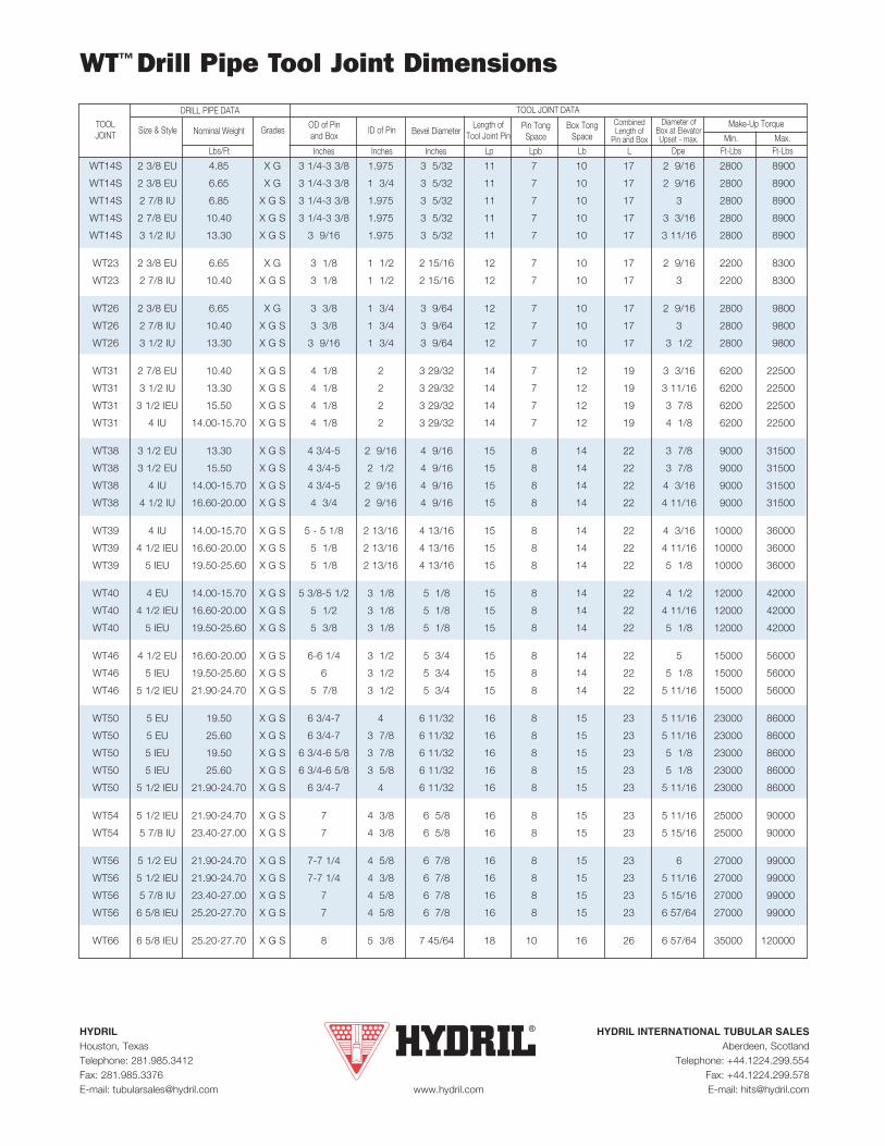
WT™ Drill Pipe Tool Joint Dimensions
HYDRIL HYDRIL INTERNATIONAL TUBULAR SALESHouston, Texas Aberdeen, ScotlandTelephone: 281.985.3412 Telephone: +44.1224.299.554Fax: 281.985.3376 Fax: +44.1224.299.578E-mail: [email protected] www.hydril.com E-mail: [email protected]
Size & Style ID of Pin
InchesInches LbLpbLp
Nominal Weight
Dpe Ft-Lbs Ft-Lbs
Make-Up TorquePin TongSpace
Bevel DiameterDiameter of
Box at ElevatorUpset - max. Min. Max.
Box TongSpace
TOOL JOINT DATA
TOOL JOINT Grades OD of Pin
and Box
LLbs/Ft
CombinedLength of
Pin and BoxInches
Length ofTool Joint Pin
WT14S 2 3/8 EU 4.85 X G 3 1/4-3 3/8 1.975 3 5/32 11 7 10 17 2 9/16 2800 8900
WT14S 2 3/8 EU 6.65 X G 3 1/4-3 3/8 1 3/4 3 5/32 11 7 10 17 2 9/16 2800 8900
WT14S 2 7/8 IU 6.85 X G S 3 1/4-3 3/8 1.975 3 5/32 11 7 10 17 3 2800 8900
WT14S 2 7/8 EU 10.40 X G S 3 1/4-3 3/8 1.975 3 5/32 11 7 10 17 3 3/16 2800 8900
WT14S 3 1/2 IU 13.30 X G S 3 9/16 1.975 3 5/32 11 7 10 17 3 11/16 2800 8900
WT23 2 3/8 EU 6.65 X G 3 1/8 1 1/2 2 15/16 12 7 10 17 2 9/16 2200 8300
WT23 2 7/8 IU 10.40 X G S 3 1/8 1 1/2 2 15/16 12 7 10 17 3 2200 8300
WT26 2 3/8 EU 6.65 X G 3 3/8 1 3/4 3 9/64 12 7 10 17 2 9/16 2800 9800
WT26 2 7/8 IU 10.40 X G S 3 3/8 1 3/4 3 9/64 12 7 10 17 3 2800 9800
WT26 3 1/2 IU 13.30 X G S 3 9/16 1 3/4 3 9/64 12 7 10 17 3 1/2 2800 9800
WT31 2 7/8 EU 10.40 X G S 4 1/8 2 3 29/32 14 7 12 19 3 3/16 6200 22500
WT31 3 1/2 IU 13.30 X G S 4 1/8 2 3 29/32 14 7 12 19 3 11/16 6200 22500
WT31 3 1/2 IEU 15.50 X G S 4 1/8 2 3 29/32 14 7 12 19 3 7/8 6200 22500
WT31 4 IU 14.00-15.70 X G S 4 1/8 2 3 29/32 14 7 12 19 4 1/8 6200 22500
WT38 3 1/2 EU 13.30 X G S 4 3/4-5 2 9/16 4 9/16 15 8 14 22 3 7/8 9000 31500
WT38 3 1/2 EU 15.50 X G S 4 3/4-5 2 1/2 4 9/16 15 8 14 22 3 7/8 9000 31500
WT38 4 IU 14.00-15.70 X G S 4 3/4-5 2 9/16 4 9/16 15 8 14 22 4 3/16 9000 31500
WT38 4 1/2 IU 16.60-20.00 X G S 4 3/4 2 9/16 4 9/16 15 8 14 22 4 11/16 9000 31500
WT39 4 IU 14.00-15.70 X G S 5 - 5 1/8 2 13/16 4 13/16 15 8 14 22 4 3/16 10000 36000
WT39 4 1/2 IEU 16.60-20.00 X G S 5 1/8 2 13/16 4 13/16 15 8 14 22 4 11/16 10000 36000
WT39 5 IEU 19.50-25.60 X G S 5 1/8 2 13/16 4 13/16 15 8 14 22 5 1/8 10000 36000
WT40 4 EU 14.00-15.70 X G S 5 3/8-5 1/2 3 1/8 5 1/8 15 8 14 22 4 1/2 12000 42000
WT40 4 1/2 IEU 16.60-20.00 X G S 5 1/2 3 1/8 5 1/8 15 8 14 22 4 11/16 12000 42000
WT40 5 IEU 19.50-25.60 X G S 5 3/8 3 1/8 5 1/8 15 8 14 22 5 1/8 12000 42000
WT46 4 1/2 EU 16.60-20.00 X G S 6-6 1/4 3 1/2 5 3/4 15 8 14 22 5 15000 56000
WT46 5 IEU 19.50-25.60 X G S 6 3 1/2 5 3/4 15 8 14 22 5 1/8 15000 56000
WT46 5 1/2 IEU 21.90-24.70 X G S 5 7/8 3 1/2 5 3/4 15 8 14 22 5 11/16 15000 56000
WT50 5 EU 19.50 X G S 6 3/4-7 4 6 11/32 16 8 15 23 5 11/16 23000 86000
WT50 5 EU 25.60 X G S 6 3/4-7 3 7/8 6 11/32 16 8 15 23 5 11/16 23000 86000
WT50 5 IEU 19.50 X G S 6 3/4-6 5/8 3 7/8 6 11/32 16 8 15 23 5 1/8 23000 86000
WT50 5 IEU 25.60 X G S 6 3/4-6 5/8 3 5/8 6 11/32 16 8 15 23 5 1/8 23000 86000
WT50 5 1/2 IEU 21.90-24.70 X G S 6 3/4-7 4 6 11/32 16 8 15 23 5 11/16 23000 86000
WT54 5 1/2 IEU 21.90-24.70 X G S 7 4 3/8 6 5/8 16 8 15 23 5 11/16 25000 90000
WT54 5 7/8 IU 23.40-27.00 X G S 7 4 3/8 6 5/8 16 8 15 23 5 15/16 25000 90000
WT56 5 1/2 EU 21.90-24.70 X G S 7-7 1/4 4 5/8 6 7/8 16 8 15 23 6 27000 99000
WT56 5 1/2 IEU 21.90-24.70 X G S 7-7 1/4 4 3/8 6 7/8 16 8 15 23 5 11/16 27000 99000
WT56 5 7/8 IU 23.40-27.00 X G S 7 4 5/8 6 7/8 16 8 15 23 5 15/16 27000 99000
WT56 6 5/8 IEU 25.20-27.70 X G S 7 4 5/8 6 7/8 16 8 15 23 6 57/64 27000 99000
WT66 6 5/8 IEU 25.20-27.70 X G S 8 5 3/8 7 45/64 18 10 16 26 6 57/64 35000 120000
DRILL PIPE DATA
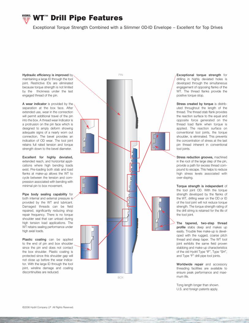
WT™ Drill Pipe FeaturesExceptional Torque Strength Combined with a Slimmer OD-ID Envelope – Excellent for Top Drives
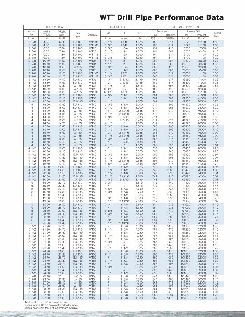
©2006 Hydril Company LP All Rights Reserved. * Multiply Ft-Lb by 1.36 to convert to N-mOptional larger ODs are available for extended wear.Optional specialized tool joint materials are available.
WT™ Drill Pipe Performance DataDRILL PIPE DATA
NominalWeight
OD
Inches Inches 1000 LbsInchesInchesLbs/Ft
AdjustedWeight
Ft-Lbs* Ft-Lbs*Pipe Tool Joint
TorsionalRatio
MECHANICAL PROPERTIES
DriftID
TOOL JOINT DATA
NominalSize
2 3/8 4.85 5.30 EU-105 WT14S 3 1/4 1.945 1.875 137 314 6670 11100 1.662 3/8 4.85 5.30 EU-105 WT14S 3 3/8 1.945 1.875 137 314 6670 11100 1.662 3/8 6.65 7.20 EU-105 WT26 3 3/8 1 3/4 1.625 194 416 8750 12300 1.402 3/8 6.65 7.10 EU-105 WT23 3 1/8 1 1/2 1.375 194 387 8750 10400 1.182 3/8 6.65 7.20 EU-105 WT14S 3 1/4 1 3/4 1.625 194 314 8750 11100 1.262 3/8 6.65 7.20 EU-105 WT14S 3 3/8 1 3/4 1.625 194 314 8750 11100 1.262 7/8 10.40 11.30 EU-105 WT31 4 1/8 2 1.875 300 697 16180 28500 1.762 7/8 10.40 11.30 EU-135 WT31 4 1/8 2 1.875 386 697 20800 28500 1.362 7/8 10.40 10.50 IU-135 WT26 3 3/8 1 3/4 1.625 386 416 20800 12300 0.592 7/8 10.40 10.50 IU-135 WT23 3 1/8 1 1/2 1.375 386 387 20800 10400 0.502 7/8 10.40 10.50 EU-135 WT14S 3 1/4 1.975 1.875 386 314 20800 11100 0.532 7/8 10.40 10.50 EU-135 WT14S 3 3/8 1.975 1.875 386 314 20800 11100 0.533 1/2 13.30 14.50 EU-135 WT38 4 3/4 2 9/16 2.438 489 877 33390 41000 1.233 1/2 13.30 14.90 EU-135 WT38 5 2 9/16 2.438 489 877 33390 41000 1.233 1/2 13.30 13.80 IU-135 WT31 4 1/8 2 1.875 489 697 33390 28500 0.853 1/2 13.30 13.30 IU-135 WT26 3 9/16 1 3/4 1.625 489 416 33390 12300 0.373 1/2 13.30 13.30 IU-135 WT14S 3 9/16 1.975 1.875 489 314 33390 11100 0.303 1/2 15.50 16.70 EU-135 WT38 4 3/4 2 1/2 2.375 581 907 37950 41000 1.083 1/2 15.50 17.10 EU-135 WT38 5 2 1/2 2.375 581 907 37950 41000 1.083 1/2 15.50 16.20 IEU-135 WT31 4 1/8 2 1.875 581 697 37950 28500 0.75
4 14.00 15.80 EU-135 WT40 5 3/8 3 1/8 3.000 514 998 41920 54000 1.294 14.00 16.00 EU-135 WT40 5 1/2 3 1/8 3.000 514 998 41920 54000 1.294 14.00 15.30 IU-135 WT39 5 2 13/16 2.688 514 910 41920 46000 1.104 14.00 15.50 IU-135 WT39 5 1/8 2 13/16 2.688 514 910 41920 46000 1.104 14.00 15.20 IU-135 WT38 4 3/4 2 9/16 2.438 514 877 41920 41000 0.984 14.00 15.60 IU-135 WT38 5 2 9/16 2.438 514 877 41920 41000 0.984 14.00 14.70 IU-135 WT31 4 1/8 2 1.875 514 697 41920 28500 0.684 15.70 17.40 EU-135 WT40 5 3/8 3 1/8 3.000 583 998 46460 54000 1.164 15.70 17.60 EU-135 WT40 5 1/2 3 1/8 3.000 583 998 46460 54000 1.164 15.70 16.90 IU-135 WT39 5 2 13/16 2.688 583 910 46460 46000 0.994 15.70 17.10 IU-135 WT39 5 1/8 2 13/16 2.688 583 910 46460 46000 0.994 15.70 16.80 IU-135 WT38 4 3/4 2 9/16 2.438 583 877 46460 41000 0.884 15.70 17.10 IU-135 WT38 5 2 9/16 2.438 583 877 46460 41000 0.884 15.70 16.20 IU-135 WT31 4 1/8 2 1.875 583 697 46460 28500 0.61
4 1/2 16.60 18.60 EU-135 WT46 6 3 1/2 3.375 595 1280 55450 70000 1.264 1/2 16.60 19.10 EU-135 WT46 6 1/4 3 1/2 3.375 595 1280 55450 70000 1.264 1/2 16.60 17.40 IEU-135 WT40 5 3/8 3 1/8 3.000 595 998 55450 54000 0.974 1/2 16.60 17.80 IEU-135 WT40 5 1/2 3 1/8 3.000 595 998 55450 54000 0.974 1/2 16.60 17.60 IEU-135 WT39 5 1/8 2 13/16 2.688 595 910 55450 46000 0.834 1/2 16.60 17.10 IU-135 WT38 4 5/8 2 9/16 2.438 595 877 55450 41000 0.744 1/2 20.00 22.00 EU-135 WT46 6 3 1/2 3.375 742 1280 66420 70000 1.054 1/2 20.00 22.50 EU-135 WT46 6 1/4 3 1/2 3.375 742 1280 66420 70000 1.054 1/2 20.00 21.50 IEU-135 WT40 5 1/2 3 1/8 3.000 742 998 66420 54000 0.814 1/2 20.00 21.30 IEU-135 WT39 5 1/8 2 13/16 2.688 742 910 66420 46000 0.694 1/2 20.00 20.80 IU-135 WT38 4 5/8 2 9/16 2.438 742 877 66420 41000 0.62
5 19.50 22.70 EU-135 WT50 6 3/4 4 3.875 712 1440 74100 109000 1.475 19.50 23.30 EU-135 WT50 7 4 3.875 712 1440 74100 109000 1.475 19.50 22.10 IEU-135 WT50 6 5/8 3 7/8 3.750 712 1533 74100 109000 1.475 19.50 22.50 IEU-135 WT50 6 3/4 3 7/8 3.750 712 1533 74100 109000 1.475 19.50 21.40 IEU-135 WT46 6 3 1/2 3.375 712 1280 74100 70000 0.945 19.50 20.80 IEU-135 WT40 5 3/8 3 1/8 3.000 712 998 74100 54000 0.735 19.50 20.80 IEU-135 WT39 5 1/8 2 13/16 2.688 712 910 74100 46000 0.625 25.60 28.50 EU-135 WT50 6 3/4 3 7/8 3.750 954 1533 94060 109000 1.165 25.60 29.10 EU-135 WT50 7 3 7/8 3.750 954 1533 94060 109000 1.165 25.60 27.90 IEU-135 WT50 6 5/8 3 5/8 3.500 954 1710 94060 109000 1.165 25.60 28.40 IEU-135 WT50 6 3/4 3 5/8 3.500 954 1710 94060 109000 1.165 25.60 27.00 IEU-135 WT46 6 3 1/2 3.375 954 1280 94060 70000 0.745 25.60 26.40 IEU-135 WT40 5 3/8 3 1/8 3.000 954 998 94060 54000 0.575 25.60 26.40 IEU-135 WT39 5 1/8 2 13/16 2.688 954 910 94060 46000 0.49
5 1/2 21.90 24.20 EU-135 WT56 7 4 5/8 4.500 787 1473 91280 132000 1.455 1/2 21.90 24.70 EU-135 WT56 7 1/4 4 5/8 4.500 787 1473 91280 132000 1.455 1/2 21.90 24.30 IEU-135 WT56 7 4 3/8 4.250 787 1685 91280 132000 1.455 1/2 21.90 24.90 IEU-135 WT56 7 1/4 4 3/8 4.250 787 1685 91280 132000 1.455 1/2 21.90 24.30 IEU-135 WT54 7 4 3/8 4.250 787 1406 91280 120000 1.315 1/2 21.90 24.40 IEU-135 WT50 6 3/4 4 3.875 787 1440 91280 109000 1.195 1/2 21.90 25.00 IEU-135 WT50 7 4 3.875 787 1440 91280 109000 1.195 1/2 21.90 23.40 IEU-135 WT46 5 7/8 3 1/2 3.375 787 1280 91280 70000 0.775 1/2 24.70 26.60 EU-135 WT56 7 4 5/8 4.500 895 1473 101830 132000 1.305 1/2 24.70 27.20 EU-135 WT56 7 1/4 4 5/8 4.500 895 1473 101830 132000 1.305 1/2 24.70 26.70 IEU-135 WT56 7 4 3/8 4.250 895 1685 101830 132000 1.305 1/2 24.70 27.30 IEU-135 WT56 7 1/4 4 3/8 4.250 895 1685 101830 132000 1.305 1/2 24.70 26.70 IEU-135 WT54 7 4 3/8 4.250 895 1406 101830 120000 1.185 1/2 24.70 26.90 IEU-135 WT50 6 3/4 4 3.875 895 1440 101830 109000 1.075 1/2 24.70 27.40 IEU-135 WT50 7 4 3.875 895 1440 101830 109000 1.075 1/2 24.70 25.80 IEU-135 WT46 5 7/8 3 1/2 3.375 895 1280 101830 70000 0.695 7/8 23.40 25.50 IU-135 WT56 7 4 5/8 4.500 844 1473 105490 132000 1.255 7/8 23.40 25.90 IU-135 WT54 7 4 3/8 4.250 844 1406 105490 120000 1.145 7/8 27.00 28.10 IU-135 WT56 7 4 5/8 4.500 961 1473 117920 132000 1.125 7/8 27.00 28.60 IU-135 WT54 7 4 3/8 4.250 961 1406 117920 120000 1.026 5/8 25.20 28.30 IEU-135 WT66 8 5 3/8 5.250 881 1654 127050 168000 1.326 5/8 25.20 27.00 IEU-135 WT56 7 4 5/8 4.500 881 1473 127050 132000 1.046 5/8 27.70 30.10 IEU-135 WT66 8 5 3/8 5.250 962 1654 137330 168000 1.226 5/8 27.70 28.80 IEU-135 WT56 7 4 5/8 4.500 962 1473 137330 132000 0.96
TypeUpset Connection
Torsional YieldTensile YieldPipe
1000 LbsTool Joint
Lbs/Ft
Exceptional torque strength fordrilling in highly deviated holes isdeveloped through the simultaneousengagement of opposing flanks of theWT. The thread flanks provide thepositive torque stop.
Stress created by torque is distrib-uted throughout the length of thethread. The thread stab flank providesthe reaction surface to the equal andopposite force generated on thethread load flank when torque isapplied. The reaction surface on conventional tool joints, the torqueshoulder, is eliminated. This preventsthe concentration of stress at the last pin thread inherent in conventionaltool joints.
Stress reduction grooves, machinedin the root of the large step of the pin,provide a path for excess thread com-pound to escape. This helps to reducehigh stress levels associated with over-doping.
Torque strength is independent ofthe tool joint OD. With the torquestrength developed by the flanks ofthe WT, drilling wear on the OD or IDof the tool joint will not reduce torquestrength. The torque strength rating ofthe drill string is retained for the life ofthe tool joint.
The tapered, two-step thread profile stabs deep and makes upeasily. Trouble free make-up is devel-oped with the rugged, coarse pitchthread and steep taper. The WT tooljoint exhibits the same field provenstabbing and make-up characteristicsof the old Hydril Type “IF”, Type “SH”,and Type “F” drill pipe tool joints.
Worldwide repair and accessorythreading facilities are available toensure peak performance and maxi-mum life.
Tong length longer than shown. U.S. and foreign patents apply.
Hydraulic efficiency is improved bymaintaining a large ID through the tooljoint. Restrictive IDs are eliminatedbecause torque strength is not limitedby the thickness under the lastengaged thread of the pin.
A wear indicator is provided by theseparation at the box face. Afterextended use, wear in the connectionwill permit additional travel of the pininto the box. A thread wear indicator isa protrusion on the pin face which isdesigned to amply deform showingadequate signs of a nearly worn outconnection. The bevel provides anindication of OD wear. The tool jointretains full rated tension and torquestrength down to the bevel diameter.
Excellent for highly deviated,extended reach, and horizontal appli-cations where high bending loadsexist. Pre-loading both stab and loadflanks at make-up allows the WT tocycle between the tension and com-pression associated with bending withminimal pin to box movement.
Pipe body sealing capability forboth internal and external pressure isprovided by the WT and lubricant.Damaged threads can be fieldrepaired, significantly reducing shoprepair frequency. There is no torqueshoulder seal that can unload duringhigh tension load applications. TheWT retains sealing performance underhigh axial loads.
Plastic coating can be applied to the end of pin and box shouldersince the pin end does not contact the box shoulder. Plastic coating isprotected since this shoulder gap willnot close up before the wear indica-tor. With the large ID through the tooljoint, wireline damage and coatingdiscontinuities are reduced.
PIN
BOX
WT™ Drill Pipe FeaturesExceptional Torque Strength Combined with a Slimmer OD-ID Envelope – Excellent for Top Drives
©2006 Hydril Company LP All Rights Reserved. * Multiply Ft-Lb by 1.36 to convert to N-mOptional larger ODs are available for extended wear.Optional specialized tool joint materials are available.
WT™ Drill Pipe Performance DataDRILL PIPE DATA
NominalWeight
OD
Inches Inches 1000 LbsInchesInchesLbs/Ft
AdjustedWeight
Ft-Lbs* Ft-Lbs*Pipe Tool Joint
TorsionalRatio
MECHANICAL PROPERTIES
DriftID
TOOL JOINT DATA
NominalSize
2 3/8 4.85 5.30 EU-105 WT14S 3 1/4 1.945 1.875 137 314 6670 11100 1.662 3/8 4.85 5.30 EU-105 WT14S 3 3/8 1.945 1.875 137 314 6670 11100 1.662 3/8 6.65 7.20 EU-105 WT26 3 3/8 1 3/4 1.625 194 416 8750 12300 1.402 3/8 6.65 7.10 EU-105 WT23 3 1/8 1 1/2 1.375 194 387 8750 10400 1.182 3/8 6.65 7.20 EU-105 WT14S 3 1/4 1 3/4 1.625 194 314 8750 11100 1.262 3/8 6.65 7.20 EU-105 WT14S 3 3/8 1 3/4 1.625 194 314 8750 11100 1.262 7/8 10.40 11.30 EU-105 WT31 4 1/8 2 1.875 300 697 16180 28500 1.762 7/8 10.40 11.30 EU-135 WT31 4 1/8 2 1.875 386 697 20800 28500 1.362 7/8 10.40 10.50 IU-135 WT26 3 3/8 1 3/4 1.625 386 416 20800 12300 0.592 7/8 10.40 10.50 IU-135 WT23 3 1/8 1 1/2 1.375 386 387 20800 10400 0.502 7/8 10.40 10.50 EU-135 WT14S 3 1/4 1.975 1.875 386 314 20800 11100 0.532 7/8 10.40 10.50 EU-135 WT14S 3 3/8 1.975 1.875 386 314 20800 11100 0.533 1/2 13.30 14.50 EU-135 WT38 4 3/4 2 9/16 2.438 489 877 33390 41000 1.233 1/2 13.30 14.90 EU-135 WT38 5 2 9/16 2.438 489 877 33390 41000 1.233 1/2 13.30 13.80 IU-135 WT31 4 1/8 2 1.875 489 697 33390 28500 0.853 1/2 13.30 13.30 IU-135 WT26 3 9/16 1 3/4 1.625 489 416 33390 12300 0.373 1/2 13.30 13.30 IU-135 WT14S 3 9/16 1.975 1.875 489 314 33390 11100 0.303 1/2 15.50 16.70 EU-135 WT38 4 3/4 2 1/2 2.375 581 907 37950 41000 1.083 1/2 15.50 17.10 EU-135 WT38 5 2 1/2 2.375 581 907 37950 41000 1.083 1/2 15.50 16.20 IEU-135 WT31 4 1/8 2 1.875 581 697 37950 28500 0.75
4 14.00 15.80 EU-135 WT40 5 3/8 3 1/8 3.000 514 998 41920 54000 1.294 14.00 16.00 EU-135 WT40 5 1/2 3 1/8 3.000 514 998 41920 54000 1.294 14.00 15.30 IU-135 WT39 5 2 13/16 2.688 514 910 41920 46000 1.104 14.00 15.50 IU-135 WT39 5 1/8 2 13/16 2.688 514 910 41920 46000 1.104 14.00 15.20 IU-135 WT38 4 3/4 2 9/16 2.438 514 877 41920 41000 0.984 14.00 15.60 IU-135 WT38 5 2 9/16 2.438 514 877 41920 41000 0.984 14.00 14.70 IU-135 WT31 4 1/8 2 1.875 514 697 41920 28500 0.684 15.70 17.40 EU-135 WT40 5 3/8 3 1/8 3.000 583 998 46460 54000 1.164 15.70 17.60 EU-135 WT40 5 1/2 3 1/8 3.000 583 998 46460 54000 1.164 15.70 16.90 IU-135 WT39 5 2 13/16 2.688 583 910 46460 46000 0.994 15.70 17.10 IU-135 WT39 5 1/8 2 13/16 2.688 583 910 46460 46000 0.994 15.70 16.80 IU-135 WT38 4 3/4 2 9/16 2.438 583 877 46460 41000 0.884 15.70 17.10 IU-135 WT38 5 2 9/16 2.438 583 877 46460 41000 0.884 15.70 16.20 IU-135 WT31 4 1/8 2 1.875 583 697 46460 28500 0.61
4 1/2 16.60 18.60 EU-135 WT46 6 3 1/2 3.375 595 1280 55450 70000 1.264 1/2 16.60 19.10 EU-135 WT46 6 1/4 3 1/2 3.375 595 1280 55450 70000 1.264 1/2 16.60 17.40 IEU-135 WT40 5 3/8 3 1/8 3.000 595 998 55450 54000 0.974 1/2 16.60 17.80 IEU-135 WT40 5 1/2 3 1/8 3.000 595 998 55450 54000 0.974 1/2 16.60 17.60 IEU-135 WT39 5 1/8 2 13/16 2.688 595 910 55450 46000 0.834 1/2 16.60 17.10 IU-135 WT38 4 5/8 2 9/16 2.438 595 877 55450 41000 0.744 1/2 20.00 22.00 EU-135 WT46 6 3 1/2 3.375 742 1280 66420 70000 1.054 1/2 20.00 22.50 EU-135 WT46 6 1/4 3 1/2 3.375 742 1280 66420 70000 1.054 1/2 20.00 21.50 IEU-135 WT40 5 1/2 3 1/8 3.000 742 998 66420 54000 0.814 1/2 20.00 21.30 IEU-135 WT39 5 1/8 2 13/16 2.688 742 910 66420 46000 0.694 1/2 20.00 20.80 IU-135 WT38 4 5/8 2 9/16 2.438 742 877 66420 41000 0.62
5 19.50 22.70 EU-135 WT50 6 3/4 4 3.875 712 1440 74100 109000 1.475 19.50 23.30 EU-135 WT50 7 4 3.875 712 1440 74100 109000 1.475 19.50 22.10 IEU-135 WT50 6 5/8 3 7/8 3.750 712 1533 74100 109000 1.475 19.50 22.50 IEU-135 WT50 6 3/4 3 7/8 3.750 712 1533 74100 109000 1.475 19.50 21.40 IEU-135 WT46 6 3 1/2 3.375 712 1280 74100 70000 0.945 19.50 20.80 IEU-135 WT40 5 3/8 3 1/8 3.000 712 998 74100 54000 0.735 19.50 20.80 IEU-135 WT39 5 1/8 2 13/16 2.688 712 910 74100 46000 0.625 25.60 28.50 EU-135 WT50 6 3/4 3 7/8 3.750 954 1533 94060 109000 1.165 25.60 29.10 EU-135 WT50 7 3 7/8 3.750 954 1533 94060 109000 1.165 25.60 27.90 IEU-135 WT50 6 5/8 3 5/8 3.500 954 1710 94060 109000 1.165 25.60 28.40 IEU-135 WT50 6 3/4 3 5/8 3.500 954 1710 94060 109000 1.165 25.60 27.00 IEU-135 WT46 6 3 1/2 3.375 954 1280 94060 70000 0.745 25.60 26.40 IEU-135 WT40 5 3/8 3 1/8 3.000 954 998 94060 54000 0.575 25.60 26.40 IEU-135 WT39 5 1/8 2 13/16 2.688 954 910 94060 46000 0.49
5 1/2 21.90 24.20 EU-135 WT56 7 4 5/8 4.500 787 1473 91280 132000 1.455 1/2 21.90 24.70 EU-135 WT56 7 1/4 4 5/8 4.500 787 1473 91280 132000 1.455 1/2 21.90 24.30 IEU-135 WT56 7 4 3/8 4.250 787 1685 91280 132000 1.455 1/2 21.90 24.90 IEU-135 WT56 7 1/4 4 3/8 4.250 787 1685 91280 132000 1.455 1/2 21.90 24.30 IEU-135 WT54 7 4 3/8 4.250 787 1406 91280 120000 1.315 1/2 21.90 24.40 IEU-135 WT50 6 3/4 4 3.875 787 1440 91280 109000 1.195 1/2 21.90 25.00 IEU-135 WT50 7 4 3.875 787 1440 91280 109000 1.195 1/2 21.90 23.40 IEU-135 WT46 5 7/8 3 1/2 3.375 787 1280 91280 70000 0.775 1/2 24.70 26.60 EU-135 WT56 7 4 5/8 4.500 895 1473 101830 132000 1.305 1/2 24.70 27.20 EU-135 WT56 7 1/4 4 5/8 4.500 895 1473 101830 132000 1.305 1/2 24.70 26.70 IEU-135 WT56 7 4 3/8 4.250 895 1685 101830 132000 1.305 1/2 24.70 27.30 IEU-135 WT56 7 1/4 4 3/8 4.250 895 1685 101830 132000 1.305 1/2 24.70 26.70 IEU-135 WT54 7 4 3/8 4.250 895 1406 101830 120000 1.185 1/2 24.70 26.90 IEU-135 WT50 6 3/4 4 3.875 895 1440 101830 109000 1.075 1/2 24.70 27.40 IEU-135 WT50 7 4 3.875 895 1440 101830 109000 1.075 1/2 24.70 25.80 IEU-135 WT46 5 7/8 3 1/2 3.375 895 1280 101830 70000 0.695 7/8 23.40 25.50 IU-135 WT56 7 4 5/8 4.500 844 1473 105490 132000 1.255 7/8 23.40 25.90 IU-135 WT54 7 4 3/8 4.250 844 1406 105490 120000 1.145 7/8 27.00 28.10 IU-135 WT56 7 4 5/8 4.500 961 1473 117920 132000 1.125 7/8 27.00 28.60 IU-135 WT54 7 4 3/8 4.250 961 1406 117920 120000 1.026 5/8 25.20 28.30 IEU-135 WT66 8 5 3/8 5.250 881 1654 127050 168000 1.326 5/8 25.20 27.00 IEU-135 WT56 7 4 5/8 4.500 881 1473 127050 132000 1.046 5/8 27.70 30.10 IEU-135 WT66 8 5 3/8 5.250 962 1654 137330 168000 1.226 5/8 27.70 28.80 IEU-135 WT56 7 4 5/8 4.500 962 1473 137330 132000 0.96
TypeUpset Connection
Torsional YieldTensile YieldPipe
1000 LbsTool Joint
Lbs/Ft
Exceptional torque strength fordrilling in highly deviated holes isdeveloped through the simultaneousengagement of opposing flanks of theWT. The thread flanks provide thepositive torque stop.
Stress created by torque is distrib-uted throughout the length of thethread. The thread stab flank providesthe reaction surface to the equal andopposite force generated on thethread load flank when torque isapplied. The reaction surface on conventional tool joints, the torqueshoulder, is eliminated. This preventsthe concentration of stress at the last pin thread inherent in conventionaltool joints.
Stress reduction grooves, machinedin the root of the large step of the pin,provide a path for excess thread com-pound to escape. This helps to reducehigh stress levels associated with over-doping.
Torque strength is independent ofthe tool joint OD. With the torquestrength developed by the flanks ofthe WT, drilling wear on the OD or IDof the tool joint will not reduce torquestrength. The torque strength rating ofthe drill string is retained for the life ofthe tool joint.
The tapered, two-step thread profile stabs deep and makes upeasily. Trouble free make-up is devel-oped with the rugged, coarse pitchthread and steep taper. The WT tooljoint exhibits the same field provenstabbing and make-up characteristicsof the old Hydril Type “IF”, Type “SH”,and Type “F” drill pipe tool joints.
Worldwide repair and accessorythreading facilities are available toensure peak performance and maxi-mum life.
Tong length longer than shown. U.S. and foreign patents apply.
Hydraulic efficiency is improved bymaintaining a large ID through the tooljoint. Restrictive IDs are eliminatedbecause torque strength is not limitedby the thickness under the lastengaged thread of the pin.
A wear indicator is provided by theseparation at the box face. Afterextended use, wear in the connectionwill permit additional travel of the pininto the box. A thread wear indicator isa protrusion on the pin face which isdesigned to amply deform showingadequate signs of a nearly worn outconnection. The bevel provides anindication of OD wear. The tool jointretains full rated tension and torquestrength down to the bevel diameter.
Excellent for highly deviated,extended reach, and horizontal appli-cations where high bending loadsexist. Pre-loading both stab and loadflanks at make-up allows the WT tocycle between the tension and com-pression associated with bending withminimal pin to box movement.
Pipe body sealing capability forboth internal and external pressure isprovided by the WT and lubricant.Damaged threads can be fieldrepaired, significantly reducing shoprepair frequency. There is no torqueshoulder seal that can unload duringhigh tension load applications. TheWT retains sealing performance underhigh axial loads.
Plastic coating can be applied to the end of pin and box shouldersince the pin end does not contact the box shoulder. Plastic coating isprotected since this shoulder gap willnot close up before the wear indica-tor. With the large ID through the tooljoint, wireline damage and coatingdiscontinuities are reduced.
PIN
BOX
R E D E F I N I N G R E L I A B I L I T Y T M
Hydril Wedge Thread™
Drill Pipe Tool JointBULLETIN 9402-E (REPLACES 9402-D)
WT™ Drill Pipe Tool Joint Dimensions
HYDRIL HYDRIL INTERNATIONAL TUBULAR SALESHouston, Texas Aberdeen, ScotlandTelephone: 281.985.3412 Telephone: +44.1224.299.554Fax: 281.985.3376 Fax: +44.1224.299.578E-mail: [email protected] www.hydril.com E-mail: [email protected]
Size & Style ID of Pin
InchesInches LbLpbLp
Nominal Weight
Dpe Ft-Lbs Ft-Lbs
Make-Up TorquePin TongSpace
Bevel DiameterDiameter of
Box at ElevatorUpset - max. Min. Max.
Box TongSpace
TOOL JOINT DATA
TOOL JOINT Grades OD of Pin
and Box
LLbs/Ft
CombinedLength of
Pin and BoxInches
Length ofTool Joint Pin
WT14S 2 3/8 EU 4.85 X G 3 1/4-3 3/8 1.975 3 5/32 11 7 10 17 2 9/16 2800 8900
WT14S 2 3/8 EU 6.65 X G 3 1/4-3 3/8 1 3/4 3 5/32 11 7 10 17 2 9/16 2800 8900
WT14S 2 7/8 IU 6.85 X G S 3 1/4-3 3/8 1.975 3 5/32 11 7 10 17 3 2800 8900
WT14S 2 7/8 EU 10.40 X G S 3 1/4-3 3/8 1.975 3 5/32 11 7 10 17 3 3/16 2800 8900
WT14S 3 1/2 IU 13.30 X G S 3 9/16 1.975 3 5/32 11 7 10 17 3 11/16 2800 8900
WT23 2 3/8 EU 6.65 X G 3 1/8 1 1/2 2 15/16 12 7 10 17 2 9/16 2200 8300
WT23 2 7/8 IU 10.40 X G S 3 1/8 1 1/2 2 15/16 12 7 10 17 3 2200 8300
WT26 2 3/8 EU 6.65 X G 3 3/8 1 3/4 3 9/64 12 7 10 17 2 9/16 2800 9800
WT26 2 7/8 IU 10.40 X G S 3 3/8 1 3/4 3 9/64 12 7 10 17 3 2800 9800
WT26 3 1/2 IU 13.30 X G S 3 9/16 1 3/4 3 9/64 12 7 10 17 3 1/2 2800 9800
WT31 2 7/8 EU 10.40 X G S 4 1/8 2 3 29/32 14 7 12 19 3 3/16 6200 22500
WT31 3 1/2 IU 13.30 X G S 4 1/8 2 3 29/32 14 7 12 19 3 11/16 6200 22500
WT31 3 1/2 IEU 15.50 X G S 4 1/8 2 3 29/32 14 7 12 19 3 7/8 6200 22500
WT31 4 IU 14.00-15.70 X G S 4 1/8 2 3 29/32 14 7 12 19 4 1/8 6200 22500
WT38 3 1/2 EU 13.30 X G S 4 3/4-5 2 9/16 4 9/16 15 8 14 22 3 7/8 9000 31500
WT38 3 1/2 EU 15.50 X G S 4 3/4-5 2 1/2 4 9/16 15 8 14 22 3 7/8 9000 31500
WT38 4 IU 14.00-15.70 X G S 4 3/4-5 2 9/16 4 9/16 15 8 14 22 4 3/16 9000 31500
WT38 4 1/2 IU 16.60-20.00 X G S 4 3/4 2 9/16 4 9/16 15 8 14 22 4 11/16 9000 31500
WT39 4 IU 14.00-15.70 X G S 5 - 5 1/8 2 13/16 4 13/16 15 8 14 22 4 3/16 10000 36000
WT39 4 1/2 IEU 16.60-20.00 X G S 5 1/8 2 13/16 4 13/16 15 8 14 22 4 11/16 10000 36000
WT39 5 IEU 19.50-25.60 X G S 5 1/8 2 13/16 4 13/16 15 8 14 22 5 1/8 10000 36000
WT40 4 EU 14.00-15.70 X G S 5 3/8-5 1/2 3 1/8 5 1/8 15 8 14 22 4 1/2 12000 42000
WT40 4 1/2 IEU 16.60-20.00 X G S 5 1/2 3 1/8 5 1/8 15 8 14 22 4 11/16 12000 42000
WT40 5 IEU 19.50-25.60 X G S 5 3/8 3 1/8 5 1/8 15 8 14 22 5 1/8 12000 42000
WT46 4 1/2 EU 16.60-20.00 X G S 6-6 1/4 3 1/2 5 3/4 15 8 14 22 5 15000 56000
WT46 5 IEU 19.50-25.60 X G S 6 3 1/2 5 3/4 15 8 14 22 5 1/8 15000 56000
WT46 5 1/2 IEU 21.90-24.70 X G S 5 7/8 3 1/2 5 3/4 15 8 14 22 5 11/16 15000 56000
WT50 5 EU 19.50 X G S 6 3/4-7 4 6 11/32 16 8 15 23 5 11/16 23000 86000
WT50 5 EU 25.60 X G S 6 3/4-7 3 7/8 6 11/32 16 8 15 23 5 11/16 23000 86000
WT50 5 IEU 19.50 X G S 6 3/4-6 5/8 3 7/8 6 11/32 16 8 15 23 5 1/8 23000 86000
WT50 5 IEU 25.60 X G S 6 3/4-6 5/8 3 5/8 6 11/32 16 8 15 23 5 1/8 23000 86000
WT50 5 1/2 IEU 21.90-24.70 X G S 6 3/4-7 4 6 11/32 16 8 15 23 5 11/16 23000 86000
WT54 5 1/2 IEU 21.90-24.70 X G S 7 4 3/8 6 5/8 16 8 15 23 5 11/16 25000 90000
WT54 5 7/8 IU 23.40-27.00 X G S 7 4 3/8 6 5/8 16 8 15 23 5 15/16 25000 90000
WT56 5 1/2 EU 21.90-24.70 X G S 7-7 1/4 4 5/8 6 7/8 16 8 15 23 6 27000 99000
WT56 5 1/2 IEU 21.90-24.70 X G S 7-7 1/4 4 3/8 6 7/8 16 8 15 23 5 11/16 27000 99000
WT56 5 7/8 IU 23.40-27.00 X G S 7 4 5/8 6 7/8 16 8 15 23 5 15/16 27000 99000
WT56 6 5/8 IEU 25.20-27.70 X G S 7 4 5/8 6 7/8 16 8 15 23 6 57/64 27000 99000
WT66 6 5/8 IEU 25.20-27.70 X G S 8 5 3/8 7 45/64 18 10 16 26 6 57/64 35000 120000
DRILL PIPE DATA