Embed Size (px)
Citation preview
NA_Deckblatt_8622.10.101.0_EN
EN-XX
Retrofitting instructions
Hydraulic Top Link
8622.10.101.08632.10.101.0

Table of contents
SAFETY NOTESProfessional Qualification ......................................................................................................................... 3Intended Use ............................................................................................................................................ 3Prior to Starting Assembly Work .............................................................................................................. 3General Safety Notes for Assembly ......................................................................................................... 4Prior to Starting Up .................................................................................................................................. 4
RETROFITTING INSTRUCTIONSRemoving the top link .............................................................................................................................. 9Attachment locations ............................................................................................................................... 18Hydraulic system ...................................................................................................................................... 18Check ....................................................................................................................................................... 19

- 3 -
Professional Qualification
• These assembly instructions are aimed exclusively at skilled staff trained for this work.
Intended Use
• Intended use is described in the machine’s Operating Instructions. The attachment or installation of additional equipment does not constitute a change to the machine’s intended use.
Prior to Starting Assembly Work
• Park the machine on firm level ground, switch off the tractor’s engine, apply the hand brake, remove the ignition key and keep safe.
• Allow the machine to come to a complete stop (rotating parts may carry on turning for a longish period). Secure machine and tractor against accidental rolling.
• Secure work area so that there can be no risk to or for other people.• Observe the statutory regulations on accident prevention.• Observe warning signs (pictograms) on the machine.
SAFETY NOTES
SAFETY NOTES
- 4 -
Prior to Starting Up
• Follow the machine’s Operating Instructions.• Check safety equipment for completeness and function.• Check oil levels.• Check machine for compressed air and oil losses.• Check tyre pressures and wheelnuts for tight fit.• Check electrical, pneumatic and hydraulic connections to the tractor.• Check service brake and parking brake for proper function.• Completely release machine’s parking brake and turn the crank handle inwards.• Place tractor’s hydraulic control unit in neutral position prior to attaching the machine. Pay attention to
lateral locking of the tractor’s three-point linkage depending on the machine type.
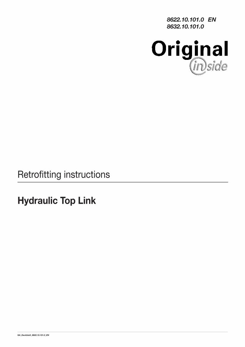
General Safety Notes for Assembly
DANGER
Risk of severe or life-threatening injuries all over the body due to getting caught up, being pulled in,
crushing and hydraulic oil escaping at high pressure! It is imperative to follow the safety notes!
• Only couple and uncouple the machine on solid level ground, secure against accidental rolling and falling over.
• Only carry out work if the PTO drive shaft and the motor have been switched off, the handbrake has been applied and the ignition key has been removed and kept safe.
• Wait until all rotating machine parts come to a complete stop!• Wear close-fitting workwear and use personal protective equipment such as safety glasses, gloves,
safety shoes and safety helmet!• Only raise the machine using lifting gear suitable for the purpose (hydraulic jack, crane, etc.) and only
support it using appropriate supporting elements.• No welding, cutting, grinding, drilling on frame, axles or other load-bearing parts.• Check nuts and bolts for tight fit.• Hoses and cables may not strain, rub or become trapped.• Attachment or installation of non-standard equipment alters the overall weight and depending on the
non-standard equipment involved may also alter the external dimensions of the machine. Pay attention to the altered dimensions in operation and particularly when driving on public roads.
Attach sufficient ballast weights to the tractor. At least 20% of the vehicle’s unladen weight on the front axle. Insufficient ballast will make tractor and machine uncontrollable when driving.
• Do not step between tractor and machine whilst attaching/coupling up. Have someone guide you in if the coupling point cannot be seen from the driver’s seat of the tractor. Do not step between tractor and machine until both have come to a stop and have been secured against accidental rolling.
• Bring the supporting devices (e.g. support legs) into the correct position in each case. Secure as prescribed!
• Do not get close to hydraulic oil escaping under high pressure.

- 5 -1100_NA_8622.10.101.0_EN
8622.10.101.0RETROFITTING INSTRUCTIONS
- 6 -1100_NA_8622.10.101.0_EN
8622.10.101.0
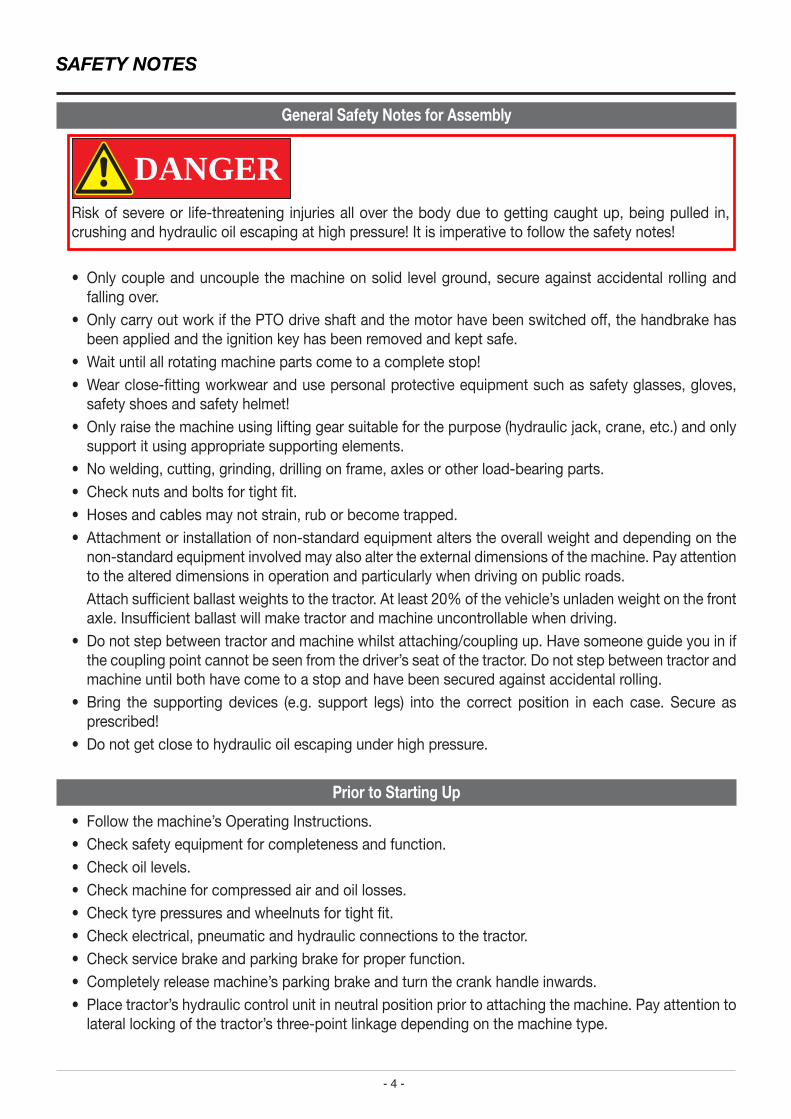
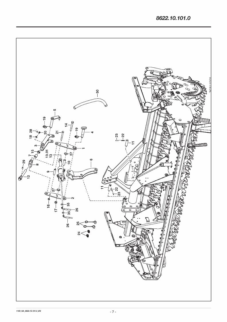
PNR TEILE-NR MENGE BENENNUNG DESIGNATION DESCRIPTION BEMERK/REMARQUE FU======================================================================================================================================== 0.01 00 8622.10.101.0 1 HYDRAULISCHER OBERLENKER LION1 VERIN HYDRAULIQUE HYDRAULIC JACK 1 00 8622.10.110.0 1 HEBEL LI SZ LEVIER LEVER 2 00 8622.10.115.0 1 HEBEL RE SZ LEVIER LEVER 3 00 8622.10.120.0 1 OBERLENKER SZ SPINDLE SPINDLE 4 00 8622.10.125.0 1 OBERLENKERBOLZEN LION BOULON PIN 5 00 8622.10.130.1 1 OBERLENKER BOLZEN SZ SPINDLE SPINDLE 6 00 8622.10.140.0 1 ADAPTER LION301 SZ RACCORD ADAPTER 7 00 8622.10.105.0 1 DISTANZ DISQUE DISTANCE SPACER 8 00 8622.10.008.0 1 BOLZEN GOUJON PIN 9 00 8622.10.007.0 1 DISTANZ DISQUE DISTANCE SPACER 10 00 8622.10.006.0 1 HUELSE ZYLINDER DOUILLE SLEEVE 11 00 872.06.027.0 2 BOLZEN AXE PIN 12 00 8622.10.109.0 1 GEWINDESTANGE BARRE FILETEE THREADED ROD 13 00 442.496 1 HYDRAULIK-ZYLINDER 65-30- 115 VERIN HYDRAULIQUE HYDR. CYLINDER 13.01 00 442.496.001 1 DICHTSATZ JEU DE JOINTS SET OF GASKETS 14 00 103.425 1 SK-SCHRAUBE M20X150 DIN931-8.8 VIS SCREW 15 00 120.167 1 SK-MUTTER M24 DIN 934 8 ZN ECROU M24 NUT M24 16 00 122.110 1 SI-MUTTER M16 DIN 980-8 ZN ECROU M16 DIN 980 NUT M16 DIN 980 17 00 122.112 1 SI-MUTTER M20 DIN 980 8 ECROU M20 NUT M20 18 00 162.403 1 SCHEIBE 28X13X3 ZN DIN 1543 RONDELLE WASHER 19 00 438.019 2 KLAPPVORSTECKER 10X45 DIN11023 GOUPILLE 10X45 PIN 10X45 20 00 103.082 1 SK-SCHRAUBE M12X16 DIN 933 VIS SCREW 21 00 103.379 1 SK-SCHR. M16X15O DIN931 8.8 ZN VIS M16X15O SCREW M16X15O 22 00 172.969 2 SPANNSTIFT 8X45 DIN 1481 GOUPILLE 8X45 ROLLPIN 8X45 23 00 173.123 2 SPANNSTIFT 5X45 DIN 1481 GOUPILLE 5X45 ROLLPIN 5X45 24 00 448.051 2 STECKER F. SCHNELLVERSCHLUSSK. AXE HYDRAULIC PLUG 25 00 448.052 2 STAUBKAPPE CACHE ROUGE CAP 26 00 447.2.307 2 HYDR.SCHLAUCH NW 8X 1350 DIN LIFT DE HYDRAULIQUE HYDRAULIC LIFT (35 27 00 163.108 2 SCHEIBE 30.2/50X3 RONDELLE WASHER 28 00 543.004 1 OMNIFIT M100 SPEZIAL PATE FREINAGE D‘VIS SCREW LOCKING PASTE 29 00 365.332 1 FEDERNDES DRUCKSTUECK M10 SZ ELASTIQUE SCREW 206I M16 30 00 447.926 1 SCHEUERSCHUTZWENDEL SSP960-200 TUYAU TUBE 35 00 415.577 4 O-RING 7,5X1,5 JOINT TORIQUE O-RING
8622/BT 0565
- 7 -1100_NA_8622.10.101.0_EN
8622.10.101.0

- 8 -1100_NA_8622.10.101.0_EN
8622.10.101.0
PNR TEILE-NR MENGE BENENNUNG DESIGNATION DESCRIPTION BEMERK/REMARQUE FU============================================================================================================================================ 0.01 00 8632.10.101.0 1 HYDRAUL. OBERLENKER LION 101-A VERIN HYDRAULIQUE HYDRAULIC JACK 1 00 8632.10.110.0 1 HEBEL LI SZ LEVIER LEVER 2 00 8632.10.115.0 1 HEBEL RE SZ LEVIER LEVER 3 00 8632.10.120.0 1 OBERLENKER SZ SPINDLE SPINDLE 4 00 8622.10.125.0 1 OBERLENKERBOLZEN LION BOULON PIN 5 00 8622.10.130.1 1 OBERLENKER BOLZEN SZ SPINDLE SPINDLE 6 00 8622.10.140.0 1 ADAPTER LION301 SZ RACCORD ADAPTER 7 00 8622.10.105.0 1 DISTANZ DISQUE DISTANCE SPACER 8 00 8622.10.008.0 1 BOLZEN GOUJON PIN 9 00 8622.10.007.0 1 DISTANZ DISQUE DISTANCE SPACER 10 00 8622.10.006.0 1 HUELSE ZYLINDER DOUILLE SLEEVE 11 00 872.06.027.0 2 BOLZEN AXE PIN 12 00 8622.10.109.0 1 GEWINDESTANGE BARRE FILETEE THREADED ROD 13 00 442.496 1 HYDRAULIK-ZYLINDER 65-30- 115 VERIN HYDRAULIQUE HYDR. CYLINDER 13.01 00 442.496.001 1 DICHTSATZ JEU DE JOINTS SET OF GASKETS 14 00 103.425 1 SK-SCHRAUBE M20X150 DIN931-8.8 VIS SCREW 15 00 120.167 1 SK-MUTTER M24 DIN 934 8 ZN ECROU M24 NUT M24 16 00 122.110 1 SI-MUTTER M16 DIN 980-8 ZN ECROU M16 DIN 980 NUT M16 DIN 980 17 00 122.112 1 SI-MUTTER M20 DIN 980 8 ECROU M20 NUT M20 18 00 162.403 1 SCHEIBE 28X13X3 ZN DIN 1543 RONDELLE WASHER 19 00 438.019 2 KLAPPVORSTECKER 10X45 DIN11023 GOUPILLE 10X45 PIN 10X45 20 00 103.082 1 SK-SCHRAUBE M12X16 DIN 933 VIS SCREW 21 00 103.379 1 SK-SCHR. M16X15O DIN931 8.8 ZN VIS M16X15O SCREW M16X15O 22 00 172.969 2 SPANNSTIFT 8X45 DIN 1481 GOUPILLE 8X45 ROLLPIN 8X45 23 00 173.123 2 SPANNSTIFT 5X45 DIN 1481 GOUPILLE 5X45 ROLLPIN 5X45 24 00 448.051 2 STECKER F. SCHNELLVERSCHLUSSK. AXE HYDRAULIC PLUG 25 00 448.052 2 STAUBKAPPE CACHE ROUGE CAP 26 00 447.2.307 2 HYDR.SCHLAUCH NW 8X 1350 DIN LIFT DE HYDRAULIQUE HYDRAULIC LIFT (35 27 00 163.108 2 SCHEIBE 30.2/50X3 RONDELLE WASHER 28 00 543.004 1 OMNIFIT M100 SPEZIAL PATE FREINAGE D‘VIS SCREW LOCKING PASTE 29 00 365.332 1 FEDERNDES DRUCKSTUECK M10 SZ ELASTIQUE SCREW 206I M16 30 00 447.926 1 SCHEUERSCHUTZWENDEL SSP960-200 TUYAU TUBE 35 00 415.577 4 O-RING 7,5X1,5 JOINT TORIQUE O-RING
8632/BT 0055
- 9 -1100_NA_8622.10.101.0_EN
8622.10.101.0
1
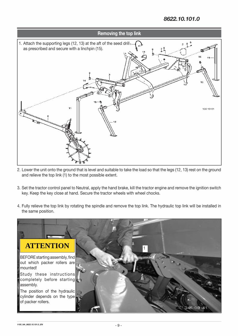
1. Attach the supporting legs (12, 13) at the aft of the seed drill as prescribed and secure with a linchpin (15).
Removing the top link
2. Lower the unit onto the ground that is level and suitable to take the load so that the legs (12, 13) rest on the ground and relieve the top link (1) to the most possible extent.
3. Set the tractor control panel to Neutral, apply the hand brake, kill the tractor engine and remove the ignition switch key. Keep the key close at hand. Secure the tractor wheels with wheel chocks.
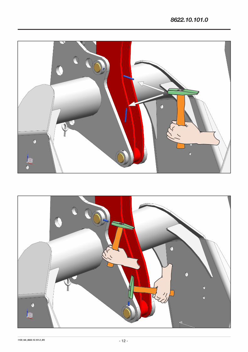
4. Fully relieve the top link by rotating the spindle and remove the top link. The hydraulic top link will be installed in the same position.
ATTENTIONBEFORE starting assembly, find out which packer rollers are mounted!
Study these instruct ions completely before starting assembly.
The position of the hydraulic cylinder depends on the type of packer rollers.
- 10 -1100_NA_8622.10.101.0_EN
8622.10.101.0
- 11 -1100_NA_8622.10.101.0_EN
8622.10.101.0
- 12 -1100_NA_8622.10.101.0_EN
8622.10.101.0
- 13 -1100_NA_8622.10.101.0_EN
8622.10.101.0
- 14 -1100_NA_8622.10.101.0_EN
8622.10.101.0
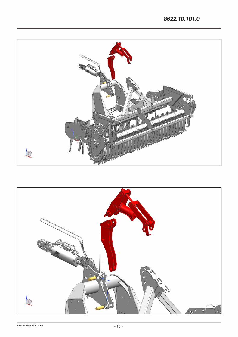
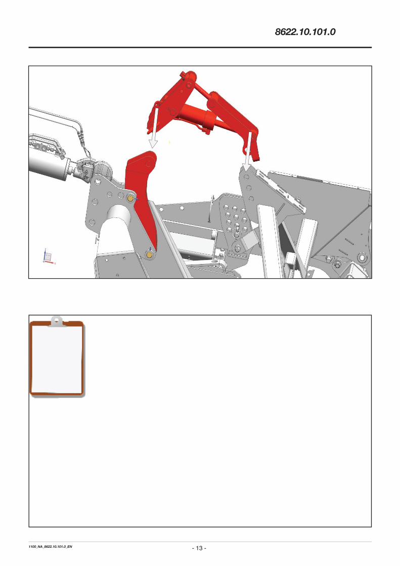
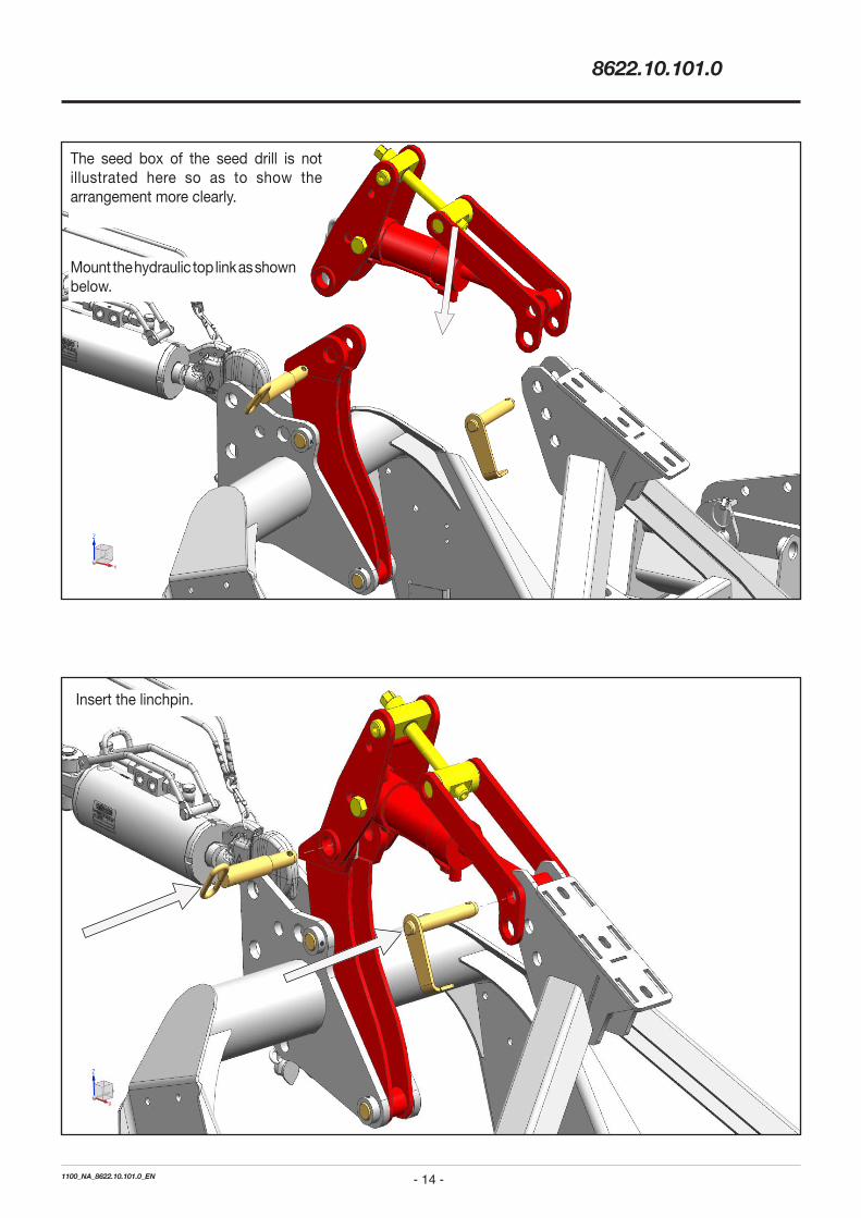
Mount the hydraulic top link as shown below.
The seed box of the seed drill is not illustrated here so as to show the arrangement more clearly.
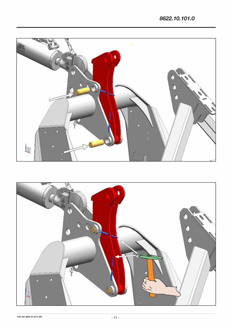
Insert the linchpin.
- 15 -1100_NA_8622.10.101.0_EN
8622.10.101.0
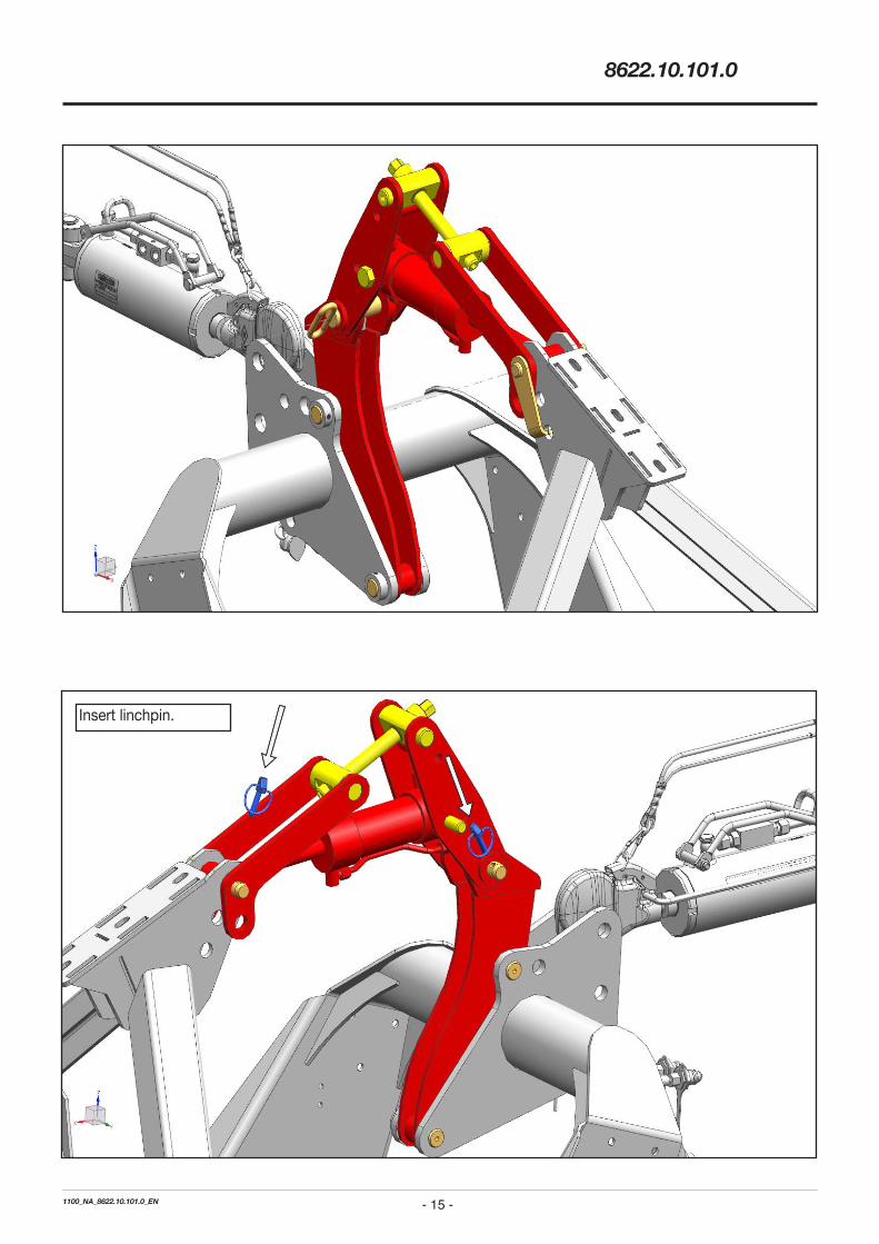
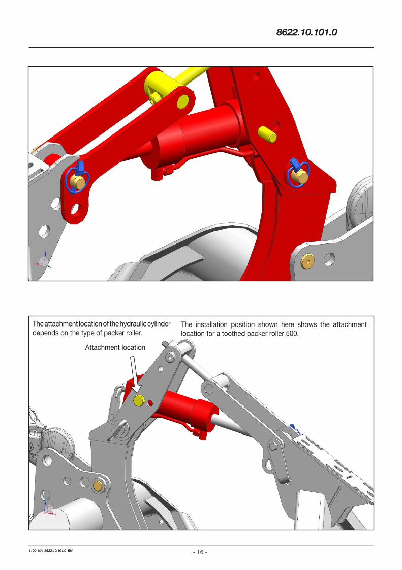
Insert linchpin.
- 16 -1100_NA_8622.10.101.0_EN
8622.10.101.0
The attachment location of the hydraulic cylinder depends on the type of packer roller.
The installation position shown here shows the attachment location for a toothed packer roller 500.
Attachment location
- 17 -1100_NA_8622.10.101.0_EN
8622.10.101.0
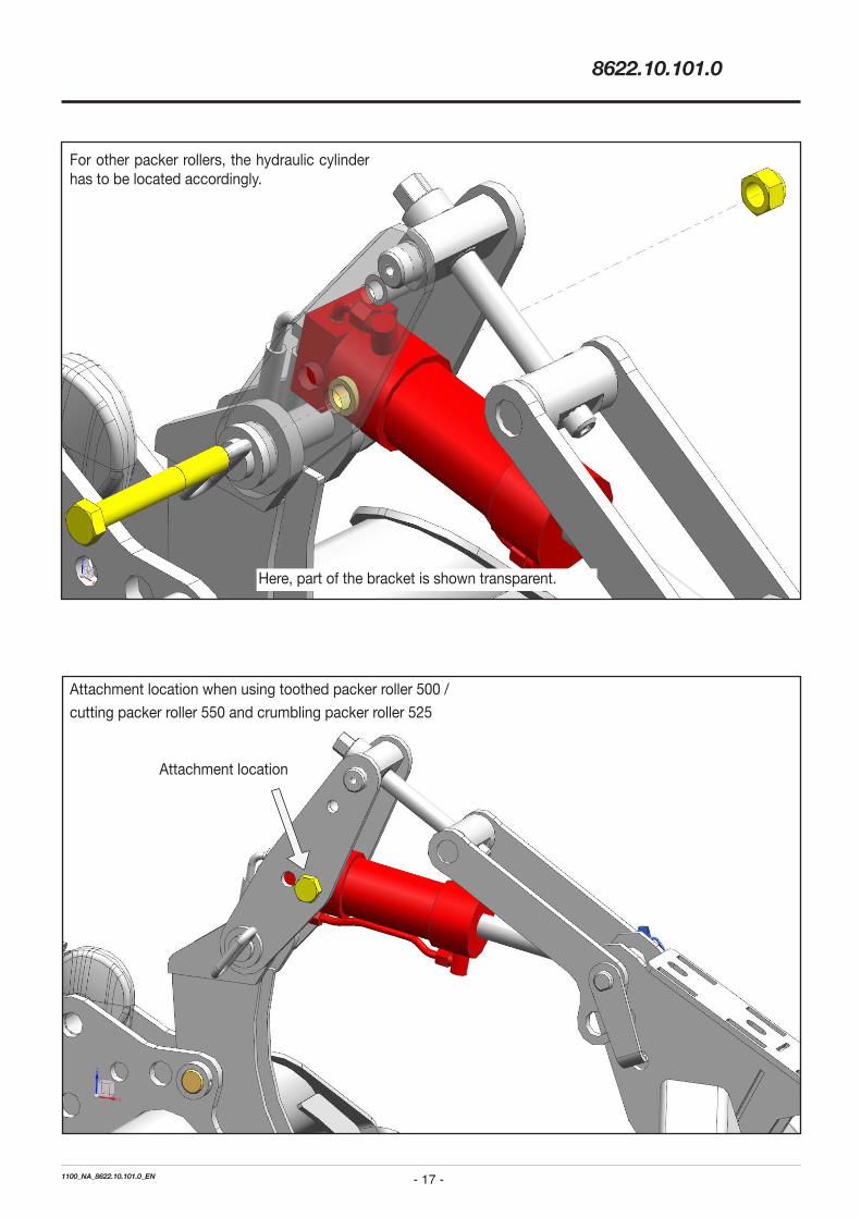
For other packer rollers, the hydraulic cylinder has to be located accordingly.
Attachment location when using toothed packer roller 500 /
cutting packer roller 550 and crumbling packer roller 525
Attachment location
Here, part of the bracket is shown transparent.

- 18 -1100_NA_8622.10.101.0_EN
8622.10.101.0
Location for toothed packer roller 500. Location for toothed packer roller 500 / cutting packer roller 550 / crumbling packer roller 525.
Attachment locations
Hydraulic system
The hydraulic hoses should be arranged inside the delivered helical abrasion guard and directed towards the tractor. The hoses have to be arranged free from pull, torsional and shear forces. The arrangement of the hoses has to ensure that enough space is available for the movement of the hydraulic cylinder.
Required hydraulic connections: 1 double-acting hydraulic connection
1 hydraulic tank connection
- 19 -1000_MA_Kontrolle_EN
EN Final Check and Self-Check
• Check all screw fittings and plug-in connections for good condition and secure fit.
• Nach Fertigstellung der Maschine sind alle Schmierstellen laut Wartungsanleitung (siehe Betriebsanleitung) erstmalig abzuschmieren, sowie die Ölstände vorhandener Getriebe etc. zu kontrollieren und falls nötig zu ergänzen.
Geeignete Schmierstoffe siehe Schmiermitteltabelle der Wartungsanleitung.
• Read carefully through the Operating Manual prior to starting the machine for the first time. It is imperative to follow the safety information it contains!
Check

PÖTTINGER Service Support Centres
AustriaPÖTTINGER Landtechnik GmbH
Industriegelände 1
4710 Grieskirchen
Phone +43 7248 600-0
Fax +43 7248 600-2513
DeutschlandPÖTTINGER Deutschland GmbH
Landsberg Service Centre
Spöttinger Straße 24
86899 Landsberg am Lech
Phone +49 8191 9299-0
Fax +49 8191 59656
PÖTTINGER Deutschland GmbH
Recke Sales and Service Centre
Steinbecker Straße 15
49509 Recke
Phone +49 5453 9114-0
Fax +49 5453 9114-14
FrancePÖTTINGER France S.a.r.l.
La Chapelle 129b
68650 Le Bonhomme
Phone +33 389 472830
Fax +33 389 472839
ItaliaPOETTINGER Italia s.r.l.
Via E. Fermi 6
29010 San Pietro in Cerro/PC
Phone +39 0523 838012
Fax +39 0523 838253

PolskaPÖTTINGER Polska
Poladowo 70
64-030 Smigiel
United KingdomAlois POTTINGER UK Ltd.
St. Marks Road 15
NN18AN Corby
Phone +44 1536 272220
Fax +44 1536 206220
IrelandPOETTINGER Ireland Ltd.
Cashel road, Clonmel
Co. Tipperary
Phone +353 52 6125766
УкраїнаPÖTTINGER Ukraine
Prywokzalna vulitsa 50, Office 215
08300 Boryspil
Phone +38 04595 710 42
РоссияOOO "POETTINGER"
Bachruschin Str. 32/1
115054 Moskau
Phone +7 495 646 89 15
Fax +7 495 646 89 16
CanadaPOETTINGER Canada Inc.
650 Route 112
J0L 1T0 St. Cesaire
Phone +1 450 469 5594
Fax +1 866 417 1683
United StatesPOETTINGER US, Inc.
393 Pilot drive
46383 Valparaiso/IN
Phone +1 219 510 5534
Fax +1 219 707 5412
POETTINGER US, Inc.
West Iona Ave
93245 Lemoore/CA
AustraliaPOETTINGER Australia PTY LTD
15 Fordson Street
Campbellfield/VIC 3061
Phone +61 3 9359 2969
PÖTTINGER Service PartnerA worldwide network of well established Service Specialist Centres is at your disposal. This regional proximity guarantees the prompt supply of spare parts, enables optimum product handover and parameterisation of machines through competent personnel.
Our service features include:• Expertise through the regular training of professional personnel.
• 24 hour online ordering service for ORIGINAL INSIDE replacement parts.
• Long-term availability of replacement parts.
• And much more…
Contact your nearest Specialist Service Centre for more information, or go to www.poetting-er.at


![02 Клиновой анкер W-FAZ/S · Диаметр анкера [в мм] m8 m10 m12 m16 m20 m24 Зона растяжения (бетон с трещинами C20/25 2), 2.4](https://img.dokumen.tips/doc/110x75/5fc590278b73e94c93527832/02-w-fazs-m8.jpg)