Embed Size (px)
Citation preview
HYDRAULIC CONTROL VALVESVahn-Tech International reserves the right to change the technical data without prior notice.
1
Features:
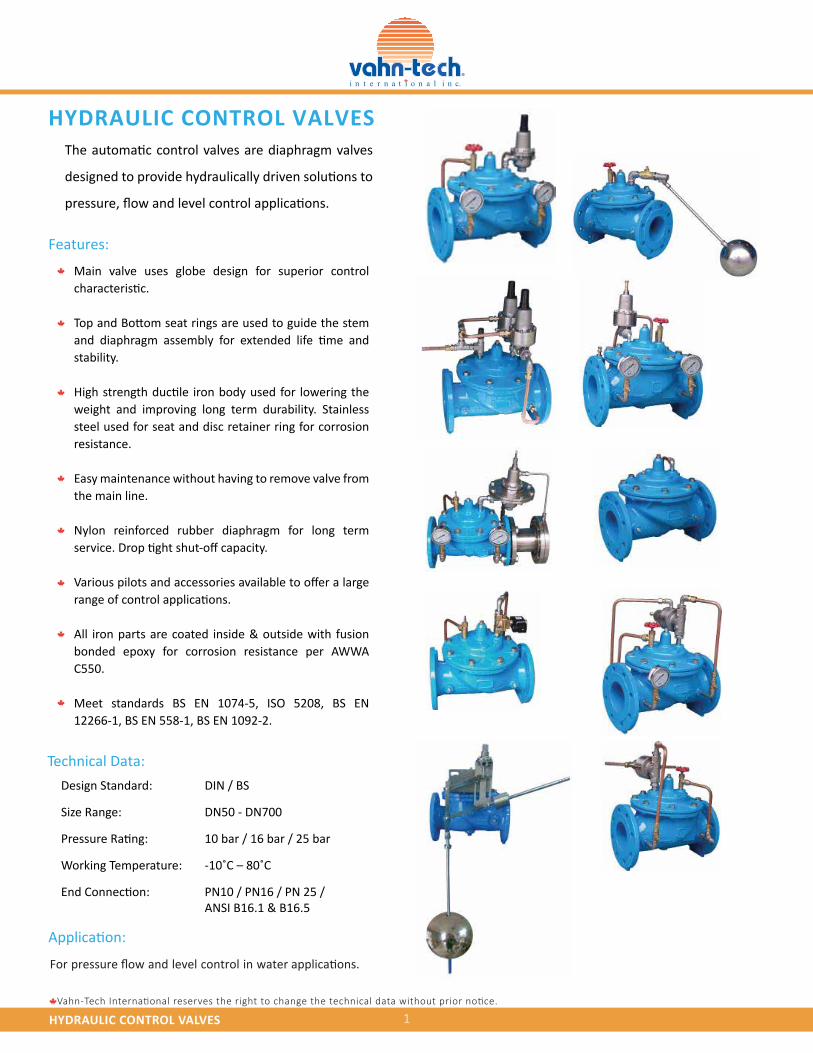
Main valve uses globe design for superior control characteristic.
Top and Bottom seat rings are used to guide the stem and diaphragm assembly for extended life time and stability.
High strength ductile iron body used for lowering the weight and improving long term durability. Stainless steel used for seat and disc retainer ring for corrosion resistance.
Easy maintenance without having to remove valve from the main line.
Nylon reinforced rubber diaphragm for long term service. Drop tight shut-off capacity.
Various pilots and accessories available to offer a large range of control applications.
All iron parts are coated inside & outside with fusion bonded epoxy for corrosion resistance per AWWA C550.
Meet standards BS EN 1074-5, ISO 5208, BS EN 12266-1, BS EN 558-1, BS EN 1092-2.
Application:
For pressure flow and level control in water applications.
Technical Data:
The automatic control valves are diaphragm valves
designed to provide hydraulically driven solutions to
pressure, flow and level control applications.
HYDRAULIC CONTROL VALVES
Design Standard: DIN / BS
Size Range: DN50 - DN700
Pressure Rating: 10 bar / 16 bar / 25 bar
Working Temperature: -10˚C – 80˚C
End Connection: PN10 / PN16 / PN 25 / ANSI B16.1 & B16.5
Vahn-Tech International reserves the right to change the technical data without prior notice.
HYDRAULIC CONTROL VALVES 2
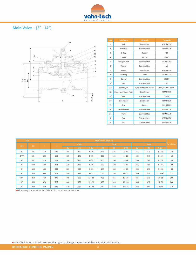
Main Valve - (2” - 14”)
L
DNKD
H
N-
d1
2
3
4
5
6
7 8
19
9
10
11
12
13
14
15
16
17
18
16
No. MaterialsParts Name Standards
1 Body ASTM A536
ASTM A536
ASTM A536
ASTM A536
2 Body Seat Stainless Steel ASTM A276
3 O-Ring Rubber NBR
4 O-Ring Rubber NBR
5 Hexagon Bolt Stainless Steel ASTM A307
6 Washer Stainless Steel A2
7 Bonnet
8 Bushing Brass ASTM B124
9 Spring Stainless Steel SS304
10 Nut Stainless Steel A2
11 Diaphragm Nylon Reinforced Rubber NBR/EPDM + Nylon
12 Diaphragm Upper Plate
13 Pin Stainless Steel SS304
14 Disc Holder
15 Seal Rubber NBR/EPDM
16 Seat Retainer Stainless Steel
17 Stem Stainless Steel
18 Plug Stainless Steel
Ductile Iron
Ductile Iron
Ductile Iron
Ductile Iron
19 Cap Carbon Steel
ASTM A276
ASTM A276
ASTM A276
ASTM A576
Size Main Dimension (mm)
Weight (kg)NPS DN L H
PN10 PN16 PN25
Ød ØK N-Ød Ød ØK N-Ød Ød ØK N-Ød
2" 50 230 139 165 125 4 - 19 165 125 4 - 19 165 125 4 - 19 14
2 ¹/₂" 65 290 159 185 145 4 - 19 185 145 4 - 19 185 145 8 - 19 19
3" 80 310 179 200 160 8 - 19 200 160 8 - 19 200 160 8 - 19 23
4" 100 350 214 220 180 8 - 19 220 180 8 - 19 235 190 8 - 23 32
6" 150 480 333 285 240 8 - 23 285 240 8 - 23 300 250 8 - 28 68
8" 200 600 407 340 295 8 - 23 34 295 12 - 23 360 310 12 - 28 125
10" 250 730 476 405 350 12 - 23 405 355 12 - 28 425 370 12 - 31 200
12" 300 850 526 460 400 12 - 23 460 410 12 - 28 485 430 16 - 31 260
14" 350 850 526 520 460 16 - 23 520 470 16 - 28 555 490 16 - 34 310
Flow way dimension for DN350 is the same as DN300.
Vahn-Tech International reserves the right to change the technical data without prior notice.
HYDRAULIC CONTROL VALVES 3
L
DNKD
HN
-d
1
2
3
4
5
7 8
19 9
10
1112
13
14
1516
17
18
6
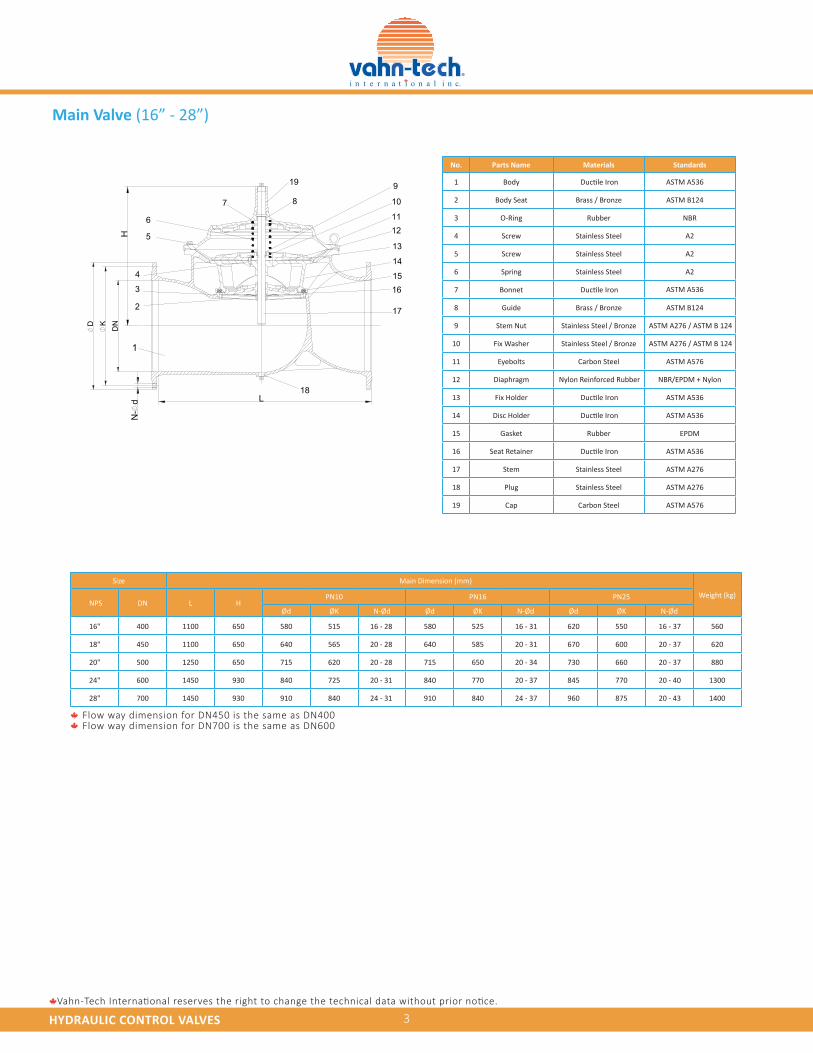
Main Valve (16” - 28”)
No. Materials Standards
1 Body
2 Body Seat Brass / Bronze
Ductile Iron
Ductile Iron
Ductile Iron
Ductile Iron
Ductile Iron
3 O-Ring Rubber NBR
4 Screw Stainless Steel A2
5 Screw Stainless Steel A2
6 Spring Stainless Steel A2
7 Bonnet
8 Guide Brass / Bronze
9 Stem Nut Stainless Steel / Bronze
10 Fix Washer Stainless Steel / Bronze
11 Eyebolts Carbon Steel
12 Diaphragm Nylon Reinforced Rubber NBR/EPDM + Nylon
ASTM A536
ASTM B124
ASTM A536
ASTM B124
ASTM A276 / ASTM B 124
ASTM A276 / ASTM B 124
ASTM A576
ASTM A536
ASTM A536
ASTM A536
ASTM A276
ASTM A276
ASTM A576
13 Fix Holder
14 Disc Holder
15 Gasket Rubber EPDM
16 Seat Retainer
17 Stem Stainless Steel
18 Plug Stainless Steel
19 Cap Carbon Steel
Parts Name
Size Main Dimension (mm)
Weight (kg)NPS DN L H
PN10 PN16 PN25
Ød ØK N-Ød Ød ØK N-Ød Ød ØK N-Ød
16" 400 1100 650 580 515 16 - 28 580 525 16 - 31 620 550 16 - 37 560
18" 450 1100 650 640 565 20 - 28 640 585 20 - 31 670 600 20 - 37 620
20" 500 1250 650 715 620 20 - 28 715 650 20 - 34 730 660 20 - 37 880
24" 600 1450 930 840 725 20 - 31 840 770 20 - 37 845 770 20 - 40 1300
28" 700 1450 930 910 840 24 - 31 910 840 24 - 37 960 875 20 - 43 1400
Flow way dimension for DN450 is the same as DN400Flow way dimension for DN700 is the same as DN600
HYDRAULIC CONTROL VALVES 4Vahn-Tech International reserves the right to change the technical data without prior notice.
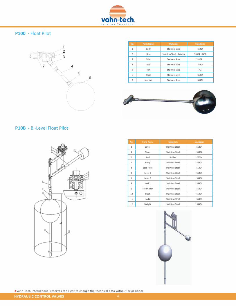
P100 - Float Pilot
P10B - Bi-Level Float Pilot
23
56
7 4
1
ZG1/
2
No. Parts Name Materials Standards
1 Body Stainless Steel SS304
2 Disc Stainless Steel + Rubber SS304 + NBR
3 Yoke Stainless Steel SS304
4 Rod Stainless Steel SS304
5 Nut Stainless Steel A2
6 Float Stainless Steel SS304
7 Jam Nut Stainless Steel SS304
No. Parts Name Materials Standards
1 Cover Stainless Steel SS304
2 Stem Stainless Steel SS304
3 Seal Rubber EPDM
4 Body Stainless Steel SS304
5 Base Plate Stainless Steel SS304
6 Level 1 Stainless Steel SS304
7 Level 2 Stainless Steel SS304
8 Hod 1 Stainless Steel SS304
9 Stop Collar Stainless Steel SS304
10 Float Stainless Steel SS304
11 Hod 2 Stainless Steel SS304
12 Weight Stainless Steel SS304
HYDRAULIC CONTROL VALVES 5Vahn-Tech International reserves the right to change the technical data without prior notice.
1110987654
2
1
3
12
1314
1615
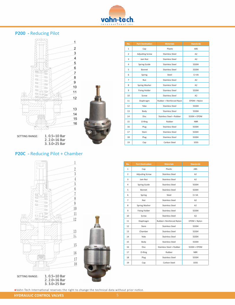
P200 - Reducing Pilot
P20C - Reducing Pilot + Chamber
No. Materials Standards
1 Cap ABS
2 Stainless Steel
Plastic
A2
3 Jam Nut Stainless Steel A2
4 Spring Guide
Adjusting Screw
Stainless Steel SS304
5 Bonnet Stainless Steel SS304
6 Spring Steel Cr-VA
7 Nut Stainless Steel A2
8 Spring Washer Stainless Steel A2
9 Fixing Holder Stainless Steel SS304
10 Screw Stainless Steel A2
11 Diaphragm Rubber + Reinforced Nyon EPDM + Nylon
12 Yoke Stainless Steel SS304
13 Body Stainless Steel SS304
14 Disc Stainless Steel + Rubber SS304 + EPDM
15 O-Ring Rubber NBR
16 Plug Stainless Steel SS304
17 Stem Stainless Steel SS304
18 Plug Stainless Steel SS304
19 Cap Carbon Steel 1035
No. Materials Standards
1 Cap ABS
2 Stainless Steel A2
3 Jam Nut Stainless Steel A2
4 Spring Guide Stainless Steel SS304
5 Bonnet Stainless Steel SS304
6 Spring Steel Cr-VA
7 Nut Stainless Steel A2
8 Spring Washer Stainless Steel A2
9 Fixing Holder Stainless Steel SS304
10 Screw Stainless Steel A2
11 Diaphragm Rubber+ Reinforced Nylon EPDM + Nylon
12 Stem Stainless Steel SS304
13 Chamber Stainless Steel SS304
14 Yoke Stainless Steel SS304
15 Body Stainless Steel SS304
16 Disc Stainless Steel + Rubber SS304 + EPDM
17 O-Ring Rubber NBR
18 Plug Stainless Steel SS304
19 Cap Carbon Steel 1035
Plastic
Adjusting Screw
SETTING RANGE: 1. 0.5~10 Bar 2. 2.0~16 Bar 3. 3.0~25 Bar
SETTING RANGE: 1. 0.5~10 Bar 2. 2.0~16 Bar 3. 3.0~25 Bar
HYDRAULIC CONTROL VALVES 6Vahn-Tech International reserves the right to change the technical data without prior notice.
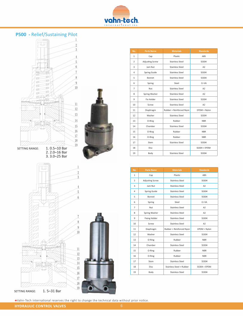
P500 - Relief/Sustaining Pilot
No. Parts Name Materials Standards
1 Cap ABS
2 Stainless Steel SS304
3 Jam Nut Stainless Steel A2
4 Spring Guide Stainless Steel SS304
5 Bonnet Stainless Steel SS304
6 Spring Steel Cr-VA
7 Nut Stainless Steel A2
8 Spring Washer Stainless Steel A2
9 Fix Holder Stainless Steel SS304
10 Screw Stainless Steel A2
11 Diaphragm Rubber + Reinforced Nyon EPDM + Nylon
12 Washer Stainless Steel SS304
13 O-Ring Rubber NBR
14 Chamber Stainless Steel SS304
15 O-Ring Rubber NBR
16 O-Ring Rubber NBR
17 Stem Stainless Steel SS304
18 Disc SS304 + EPDM
19 Body Stainless Steel SS304
Plastic
Adjusting Screw
No. Parts Name Materials Standards
1 Cap ABS
2 Stainless Steel SS304
3 Jam Nut Stainless Steel A2
4 Spring Guide Stainless Steel SS304
5 Bonnet Stainless Steel SS304
6 Spring Steel Cr-VA
7 Nut Stainless Steel A2
8 Spring Washer Stainless Steel A2
9 Fixing Holder Stainless Steel SS304
10 Screw Stainless Steel A2
11 Diaphragm Rubber + Reinforced Nyon EPDM + Nylon
12 Washer Stainless Steel SS304
13 O-Ring Rubber NBR
14 Chamber Stainless Steel SS304
15 O-Ring Rubber NBR
16 O-Ring Rubber NBR
17 Stem Stainless Steel SS304
18 Disc Stainless Steel + Rubber SS304 + EPDM
19 Body Stainless Steel SS304
Plastic
Adjusting Screw
SETTING RANGE: 1. 0.5~10 Bar 2. 2.0~16 Bar 3. 3.0~25 Bar
SETTING RANGE: 1. 5~31 Bar
HYDRAULIC CONTROL VALVES 7Vahn-Tech International reserves the right to change the technical data without prior notice.
1
23
4
5
Isolation Valve Isolation Valve
Y Strainer A100 Flexible Joint
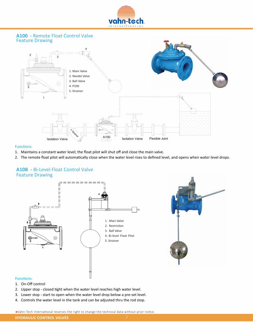
1. Main Valve
2. Restriction
3. Ball Valve
4. Bi-level Float Pilot
5. Strainer
A100 - Remote Float Control ValveFeature Drawing
Feature DrawingA10B - Bi-Level Float Control Valve
Functions:1.2.
Functions:1.2.3.4.
On-Off controlUpper stop - closed tight when the water level reaches high water level.Lower stop - start to open when the water level drop below a pre-set level.Controls the water level in the tank and can be adjusted thru the rod stop.
Maintains a constant water level; the float pilot will shut off and close the main valve.The remote float pilot will automatically close when the water level rises to defined level, and opens when water level drops.
1. Main Valve
2. Needel Valve
3. Ball Valve
4. P100
5. Strainer
HYDRAULIC CONTROL VALVES 8Vahn-Tech International reserves the right to change the technical data without prior notice.
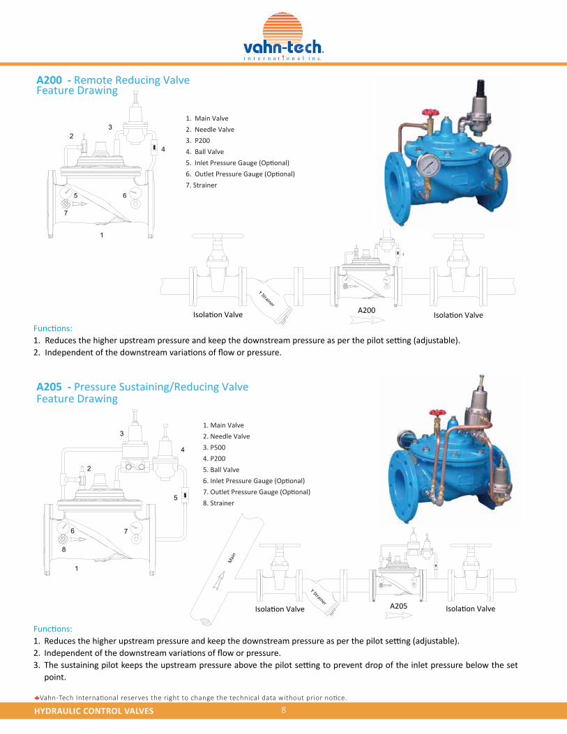
A200 - Remote Reducing ValveFeature Drawing
Feature DrawingA205 - Pressure Sustaining/Reducing Valve
2
3
4
1
6
5
7
8
Isolation Valve Isolation Valve
Y Strainer A205
Mai
n
23
1
65
4
7
Isolation ValveIsolation Valve
Y StrainerA200
4
Functions:1. 2.
Functions:1.2.3.
Reduces the higher upstream pressure and keep the downstream pressure as per the pilot setting (adjustable).Independent of the downstream variations of flow or pressure.
Reduces the higher upstream pressure and keep the downstream pressure as per the pilot setting (adjustable).Independent of the downstream variations of flow or pressure.The sustaining pilot keeps the upstream pressure above the pilot setting to prevent drop of the inlet pressure below the set point.
1. Main Valve
2. Needle Valve
3. P200
4. Ball Valve
5. Inlet Pressure Gauge (Optional)
6. Outlet Pressure Gauge (Optional)
7. Strainer
1. Main Valve
2. Needle Valve
3. P500
4. P200
5. Ball Valve
6. Inlet Pressure Gauge (Optional)
7. Outlet Pressure Gauge (Optional)
8. Strainer
HYDRAULIC CONTROL VALVES 9Vahn-Tech International reserves the right to change the technical data without prior notice.
2
1
Isolation Valve Isolation Valve
Y Strainer A300
1
6
2
3
45
7
3
Isolation Valve Isolation Valve
Y Strainer A2A5
Mai
n
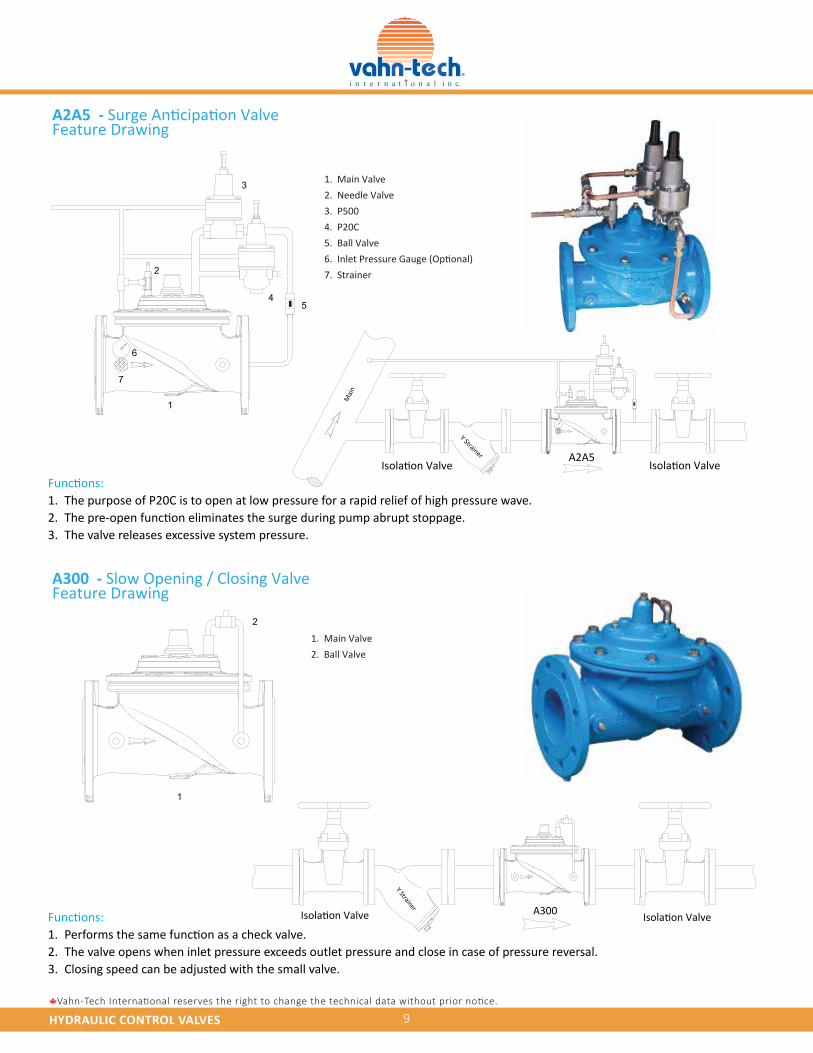
A2A5 - Surge Anticipation ValveFeature Drawing
A300 - Slow Opening / Closing ValveFeature Drawing
Functions:1. 2.3.
The purpose of P20C is to open at low pressure for a rapid relief of high pressure wave.The pre-open function eliminates the surge during pump abrupt stoppage.The valve releases excessive system pressure.
Functions:1. 2.3.
Performs the same function as a check valve.The valve opens when inlet pressure exceeds outlet pressure and close in case of pressure reversal. Closing speed can be adjusted with the small valve.
1. Main Valve
2. Needle Valve
3. P500
4. P20C
5. Ball Valve
6. Inlet Pressure Gauge (Optional)
7. Strainer
1. Main Valve
2. Ball Valve
HYDRAULIC CONTROL VALVES 10Vahn-Tech International reserves the right to change the technical data without prior notice.
Feature Drawing
Feature Drawing
2
3
4
1
5
6
A500Isolation Valve
Y Strainer
Mai
n
3
4
Isolation Valve Isolation Valve
Y Strainer A400
4
2
3
1
5
4
6
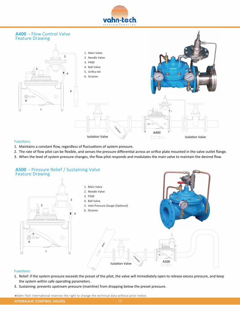
A400 - Flow Control Valve
A500 - Pressure Relief / Sustaining Valve
Functions:1. 2.3.
Maintains a constant flow, regardless of fluctuations of system pressure.The rate of flow pilot can be flexible, and senses the pressure differential across an orifice plate mounted in the valve outlet flange.When the level of system pressure changes, the flow pilot responds and modulates the main valve to maintain the desired flow.
Functions:1.
3.
Relief: if the system pressure exceeds the preset of the pilot, the valve will immediately open to release excess pressure, and keep the system within safe operating parameters.Sustaining: prevents upstream pressure (mainline) from dropping below the preset pressure.
1. Main Valve
2. Needle Valve
3. P400
4. Ball Valve
5. Orifice Kit
6. Strainer
1. Main Valve
2. Needle Valve
3. P500
4. Ball Valve
5. Inlet Pressure Gauge (Optional)
6. Strainer
HYDRAULIC CONTROL VALVES 11Vahn-Tech International reserves the right to change the technical data without prior notice.
2
3
4
1
5
2
1
5 6
3
4
7
Isolation ValveIsolation Valve
Y Strainer A600
HVAC system
Isolation ValveIsolation Valve
Y Strainer A800
Supp
ly
Retu
rn
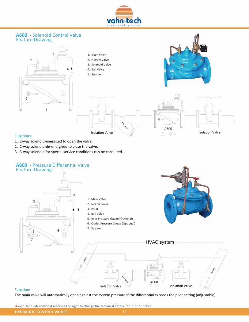
Function:The main valve will automatically open against the system pressure if the differential exceeds the pilot setting (adjustable).
A800 - Pressure Differential ValveFeature Drawing
A600 - Solenoid Control ValveFeature Drawing
Functions:1. 2.3.
2-way solenoid-energized to open the valve.2-way solenoid-de-energized to close the valve.3-way solenoid for special service conditions can be consulted.
1. Main Valve
2. Needle Valve
3. Solenoid Valve
4. Ball Valve
5. Strainer
1. Main Valve
2. Needle Valve
3. P800
4. Ball Valve
5. Inlet Pressure Gauge (Optional)
6. Outlet Pressure Gauge (Optional)
7. Strainer
HYDRAULIC CONTROL VALVES
VA H N - T E C H I n t e r n a t i o n a l I n c .2608-88, Blue Jays Way, Toronto, Ontario, M5V 0L7, Canada
Tel.: +1 416 342 0001 E-mail: [email protected]
www.vahn-tech.com
12
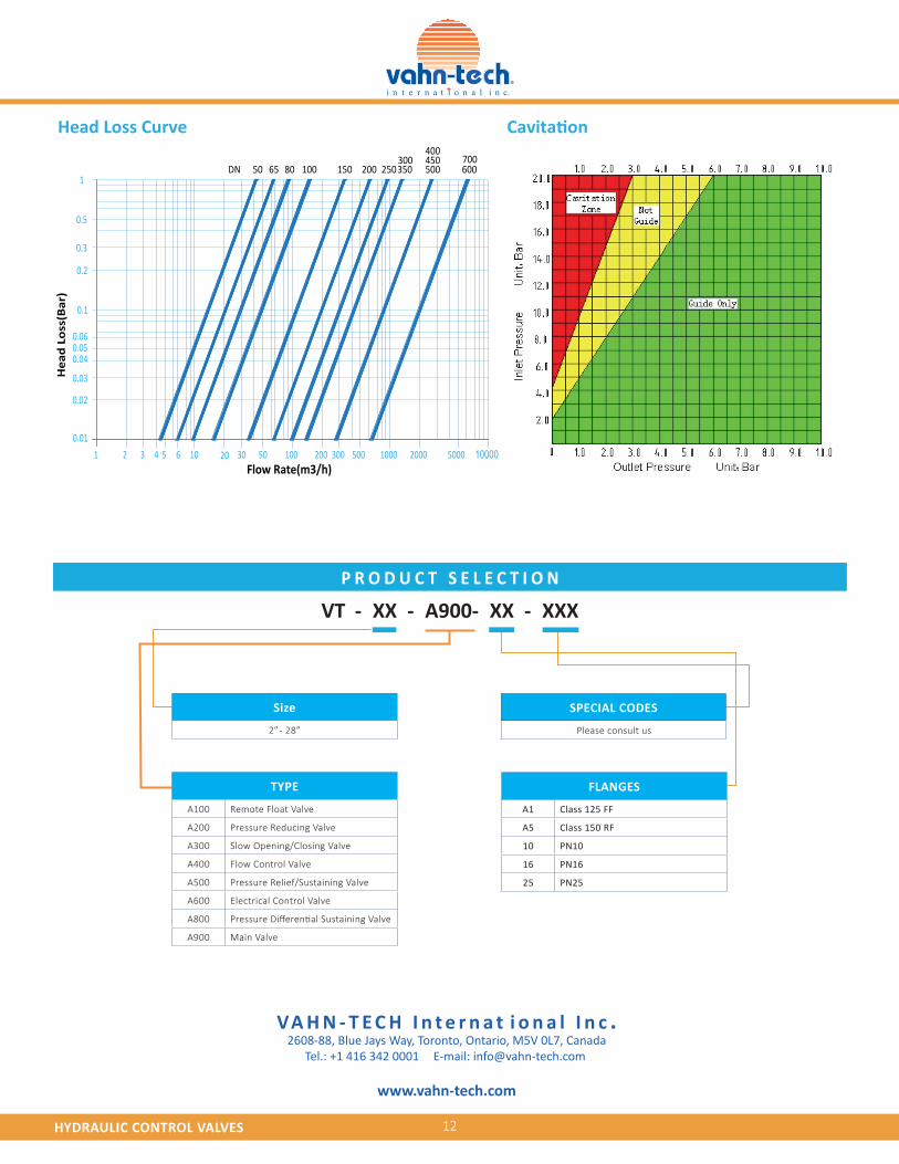
Head Loss Curve Cavitation
1 2 3 4 5 6 10 20 30 50 100 200 300 500 1000 2000 5000
0.02
0.01
0.03
0.040.050.06
0.1
0.2
0.3
0.5
1
Hea
d Lo
ss(B
ar)
Flow Rate(m3/h)
50 65 80 100 150 200 250350300 450
400
500 600
10000
DN700
VT - XX - A900- XX - XXX
TYPE
A100 Remote Float Valve
A200 Pressure Reducing Valve
A300 Slow Opening/Closing Valve
A400 Flow Control Valve
A500 Pressure Relief/Sustaining Valve
A600 Electrical Control Valve
A800 Pressure Differential Sustaining Valve
A900 Main Valve
Size
2” - 28”
FLANGES
A1 Class 125 FF
A5 Class 150 RF
10 PN10
16 PN16
25 PN25
SPECIAL CODES
Please consult us