Embed Size (px)
Citation preview
HW User Guide 1VV0301291, Rev. 12 – 2017-06-08
Stollmann is a Telit brand.
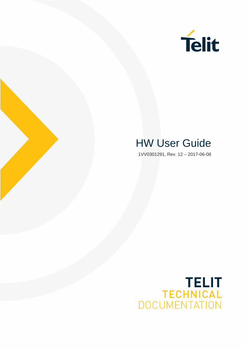
BlueMod+B20/AI BlueMod+B20/AP
BlueMod+B20/AP/L
Hardware Reference
Release r12

BlueMod+B20/AI BlueMod+B20/AP
BlueMod+B20/AP/L
Hardware Reference Stollmann is a Telit brand.
Page 3 of 65
Note
This device was developed for the purpose of communication in an office
environment. It is intended solely for our industrial clients for physical integration into
their own technical products after careful examination by experienced technical
personnel for its suitability for the intended purpose. The device was not developed
for or intended for use in any specific customer application. The firmware of the
device may have to be adapted to the specific intended modalities of use or even
replaced by other firmware in order to ensure flawless function in the respective
areas of application. Performance data (range, power requirements, etc.) may
depend on the operating environment, the area of application, the configuration, and
method of control, as well as on other conditions of use; these may deviate from the
technical specifications, the Design Guide specifications, or other product
documentation. The actual performance characteristics can be determined only by
measurements subsequent to integration. Variations in the performance data of
mass-produced devices may occur due to individual differences between such
devices. Device samples were tested in a reference environment for compliance
with the legal requirements applicable to the reference environment. No
representation is made regarding the compliance with legal, regulatory, or other
requirements in other environments. No representation can be made and no
warranty can be assumed regarding the suitability of the device for a specific
purpose as defined by our customers. Telit reserves the right to make changes to
the hardware or firmware or to the specifications without prior notice or to replace
the device with a successor model. Of course, any changes to the hardware or
firmware of any devices for which we have entered into a supply agreement with our
customers will be made only if, and only to the extent that, such changes can
reasonably be expected to be acceptable to our customers. No general commitment
will be made regarding periods of availability; these must be subject to individual
agreement. All agreements are subject to our Terms and Conditions for Deliveries
and Payments.
Copyright © 2005-2017 Telit Wireless Solutions GmbH
Trademarks
The Bluetooth® word mark and logos are owned by the Bluetooth SIG, Inc. and any
use of such marks by Telit is under license. Other trademarks and trade names are
those of their respective owners.
BlueMod+B20/AI BlueMod+B20/AP
BlueMod+B20/AP/L
Hardware Reference Stollmann is a Telit brand.
Page 4 of 65
Table of contents
1 Introduction ....................................................................................................... 7
1.1 Feature Summary ......................................................................................... 7
1.2 Applications .................................................................................................. 8
1.2.1 Cable Replacement, Serial Point-to-point .............................................. 8
1.2.2 Cable Replacement, Multipoint ............................................................. 9
1.2.3 Terminal Server .................................................................................... 9
1.2.4 PC Client ............................................................................................. 10
2 Block Diagram ................................................................................................. 11
3 Application Interface ........................................................................................ 12
3.1 Power Supply .............................................................................................. 12
3.2 Reset .......................................................................................................... 13
3.2.1 UART configuration in reset ............................................................... 13
3.3 Serial Interface ............................................................................................ 14
3.3.1 3-wire Serial Interface ......................................................................... 14
3.3.2 Baudrate tolerance .............................................................................. 14
3.4 PIO Interface ............................................................................................... 15
3.5 I2C Interface ................................................................................................ 15
3.6 Bluetooth radio Interface ............................................................................. 15
3.7 PCM Interface ............................................................................................. 16
3.8 USB Interface ............................................................................................. 17
3.8.1 D+, D- ................................................................................................. 17
3.8.2 USB Self-Powered Mode .................................................................... 17
3.8.3 USB Bus-Powered Mode .................................................................... 18
3.9 Serial Peripheral Interface ........................................................................... 19
4 Pin Description ................................................................................................ 20
4.1 Pin Numbering ............................................................................................ 20
4.2 Pin Description ............................................................................................ 22
4.2.1 General Pin Description ...................................................................... 22
4.2.2 Application Specific Pin Description .................................................... 24

BlueMod+B20/AI BlueMod+B20/AP
BlueMod+B20/AP/L
Hardware Reference Stollmann is a Telit brand.
Page 5 of 65
4.2.2.1 SPP Pin Configuration DCE Mode ................................................ 24
4.2.2.2 SPP Pin Configuration DTE Mode ................................................ 26
5 Electrical Characteristics ................................................................................. 28
5.1 Absolute Maximum Ratings ........................................................................ 28
5.2 Electrical Requirements .............................................................................. 28
5.3 Environmental Requirements ...................................................................... 28
5.4 Digital I/O including RESET# ...................................................................... 29
5.5 AIO-Interface .............................................................................................. 29
5.6 USB-Interface ............................................................................................. 30
5.7 Power consumption and power down modes .............................................. 30
5.7.1 HCI Configuration ............................................................................... 30
5.7.2 SPP Configuration .............................................................................. 30
5.8 RF performance .......................................................................................... 31
5.9 Power-up time ............................................................................................. 31
6 Mechanical Characteristics .............................................................................. 32
6.1 Dimensions ................................................................................................. 32
6.2 Recommended Land Pattern ...................................................................... 34
6.3 Re-flow Temperature-Time Profile .............................................................. 36
6.4 Restricted Area ........................................................................................... 37
6.5 Housing Guidelines ..................................................................................... 38
6.6 Antenna Issues ........................................................................................... 39
6.7 Safety Guidelines ........................................................................................ 42
7 Approvals/Certifications ................................................................................... 43
7.1 Declaration of conformity CE RED .............................................................. 43
7.2 FCC/IC Compliance .................................................................................... 44
7.2.1 FCC Grant .......................................................................................... 45
7.2.2 IC Grant .............................................................................................. 46
7.2.3 FCC/IC Statement ............................................................................... 47
7.2.4 Caution ............................................................................................... 47
7.2.5 FCC Warning ...................................................................................... 47

BlueMod+B20/AI BlueMod+B20/AP
BlueMod+B20/AP/L
Hardware Reference Stollmann is a Telit brand.
Page 6 of 65
7.2.6 RF-exposure Statement ...................................................................... 47
7.2.7 Labeling requirements for the End Product ......................................... 48
7.3 Japanese Certification ................................................................................ 48
7.3.1 Japanese Telecom Network Certificate ............................................... 49
7.3.2 Japanese Radio Certificate ................................................................. 50
7.4 Bluetooth Qualification ................................................................................ 51
7.4.1 BlueMod+B20 with BT 2.0+ EDR supporting SPP profile .................... 52
7.4.2 BlueMod+B20 with BT 2.1+ EDR supporting SPP profile .................... 53
7.4.3 BlueMod+B20 with BT 2.1+ EDR supporting SPP,HID,OPP profile ..... 54
7.5 RoHS Declaration ....................................................................................... 55
8 Related Documents ......................................................................................... 56
9 Packing ........................................................................................................... 57
9.1 Tape ........................................................................................................... 57
9.2 Reel ............................................................................................................ 57
10 Label Information ............................................................................................. 58
10.1 Module Label .............................................................................................. 58
10.2 Package Label ............................................................................................ 59
11 Ordering Information........................................................................................ 60
12 History ............................................................................................................. 61

BlueMod+B20/AI BlueMod+B20/AP
BlueMod+B20/AP/L
Hardware Reference Stollmann is a Telit brand.
Page 7 of 65
1 Introduction
This Hardware Reference documents how the BlueMod+B20/AI,
BlueMod+B20/AP/L and BlueMod+B20/AP can be integrated into customer
systems. It addresses hardware specifications of the BlueMod+B20/AI,
BlueMod+B20/AP/L and BlueMod+B20/AP and further the requirements for the
hardware environments for the BlueMod+B20/AI and BlueMod+B20/AP.
For detailed information about software interfaces refer to [3], [4]..
For the latest version of this document please check the following URL:
http://www.telit.com/support and select “Downloadzone”.
1.1 Feature Summary
Bluetooth specification V2.0+EDR (Enhanced Data Rate), or Bluetooth
specification V2.1 compliant
CSR BlueCore4-External inside
Complete Co-location and Co-existence with 802.11 (AWMA, AFH and SFH)
Fast Connection Setup
RF output power class 2 with power control
Supply Voltage 3.3V
Internal crystal oscillator (26 MHz or 16 MHz)
Surface mount type:
BlueMod+B20/AI: 14.5 x 28.0 x 2.7 mm
BlueMod+B20/AP: 14.5 x 20.0 x 2.0 mm
BlueMod+B20/AP/L: 14.5 x 28.0 x 2.7 mm
Bluetooth enhanced data rate up to 2178kbps asymmetric
Support for all Bluetooth power saving modes (Park, Sniff, Hold)
µ-law, A-law and CVSD transcoders on SCO channel
13 or 16 bit linear, 8 bit µ-law or a-law PCM interface
Full 8- to 128-bit encryption
High sensitivity design (-81 dBm typ.)
USB, UART and I2C interface
11 digital + 2 analog IO’s for individual usage by embedded software
16bit RISC core for embedded profiles or application software
Power control
Manufactured in conformance with RoHS

BlueMod+B20/AI BlueMod+B20/AP
BlueMod+B20/AP/L
Hardware Reference Stollmann is a Telit brand.
Page 8 of 65
1.2 Applications
The BlueMod+B20/AI, BlueMod+B20/AP/L and BlueMod+B20/AP can be used in
different applications. Some typical applications are described in this chapter.
1.2.1 Cable Replacement, Serial Point-to-point
To establish a cable replacement connection between two devices with a serial
interface, the BlueMod+B20/AI, BlueMod+B20/AP/L or BlueMod+B20/AP can be
used.
Bluetooth
RS-232
Bluetooth Adapter Control Unit
BlueMod+B20

BlueMod+B20/AI BlueMod+B20/AP
BlueMod+B20/AP/L
Hardware Reference Stollmann is a Telit brand.
Page 9 of 65
1.2.2 Cable Replacement, Multipoint
Since several devices may be connected with a master device via Bluetooth, several
end devices can also be multiplexed via Bluetooth. This set up is shown below for a
desktop device.
Bluetooth
Multiplexing protocolRS-232Bluetooth
Adapter
Control Unit
Device
Bluetooth
BlueMod
+B20
BlueMod+B20
In order to handle multiple links a multiplexing protocol is required for the
communication between the devices, the Bluetooth Adapter and the host. The
Bluetooth Adapter has to be adjusted to the routing scheme of the protocol to
transmit the data in an appropriate way. This includes Bluetooth connection control
(i.e. are the Bluetooth links permanently active or only on demand) and data
distribution (i.e. are all data from the host to be forwarded to all devices or only
depending on the address header; are data from the devices are transmitted to the
host transparently or is an address header to be added). In case you have a
multipoint application please contact Telit for specific support.
1.2.3 Terminal Server
Bluetooth
Terminal Server
Bluetooth Adapter
Bluetooth
RS-232
BlueMod+B20
BlueMod+B20

BlueMod+B20/AI BlueMod+B20/AP
BlueMod+B20/AP/L
Hardware Reference Stollmann is a Telit brand.
Page 10 of 65
1.2.4 PC Client
The BlueMod+B20/AI, BlueMod+B20/AP/L or BlueMod+B20/AP can be used as a
Bluetooth Client and as such can establish connections with other Bluetooth
interfaces, e.g. in PCs.
Bluetooth
PC
PCMCIAUSB
Bluetooth Adapter
BlueMod+B20

BlueMod+B20/AI BlueMod+B20/AP
BlueMod+B20/AP/L
Hardware Reference Stollmann is a Telit brand.
Page 11 of 65
2 Block Diagram
Flash8Mb
BlueCore 4External
VCC
BlueMod+B20/AI
TM
ComboFilter
RE
SE
T
SP
I
UA
RT
PC
M
PIO
US
B
1444
12+2
2
GND
3.3V
26MHz
onboardantenna
Figure: BlueMod+B20/AI block diagram
Flash8Mb
BlueCore 4External
VCC
BlueMod+B20/AP
TM
ComboFilter
RE
SE
T
SP
I
UA
RT
PC
M
PIO
US
B
1444
12+2
2
GND
3.3V
26MHz
external Antenna
Figure: BlueMod+B20/AP, BlueMod+B20/AP/L block diagram

BlueMod+B20/AI BlueMod+B20/AP
BlueMod+B20/AP/L
Hardware Reference Stollmann is a Telit brand.
Page 12 of 65
3 Application Interface
3.1 Power Supply
BlueMod+B20/AI, BlueMod+B20/AP/L and BlueMod+B20/AP require a power
supply with the following characteristics:
Typical : 3.3VDC, min.: 2.8VDC – max.: 3.6VDC, low noise (10mV), >80mA peak
Due to the technological requirements and the pulsed radio transmission the supply
needs to be fed by an ultra-fast (response time 20µs) linear regulator placed as
close as possible to the VSUP pin (22). Functionality has been verified with the
following types: TOREX: XC6204x332xx
It is also recommended to place a low ESR capacitor with at least 10µF as close as
possible to the VSUP pin (22).
NOTE: You must ensure that during operation the supply voltage never drops
below 2.8 VDC. Otherwise the flash contents (firmware and/or configuration data)
can get lost.

BlueMod+B20/AI BlueMod+B20/AP
BlueMod+B20/AP/L
Hardware Reference Stollmann is a Telit brand.
Page 13 of 65
3.2 Reset
BlueMod+B20/AI, BlueMod+B20/AP/L and BlueMod+B20/AP are equipped with
circuitry for generating Power ON Reset from the internal core voltage. A reset is
generated when the core voltage falls below typically 1.5V and is released when it
rises above typically 1.6V.
Via Pin 31 an external reset is generated by holding RESET# at ≤ 0.3V for ≥ 5ms.
It is strongly recommended to use external Power ON Reset circuitry, which holds
RESET# at ≤ 0.3V for ≥ 5ms after VSUP has stabilized in the recommended voltage
range.
The following table shows the pin states of BlueMod+B20 on reset.
Pin Name State: BlueMod+B20
PIO[11:0] Input with weak pull down
PCM_OUT Output tri-stated with weak pull down
PCM_IN Input with weak pull down
PCM_SYNC Input with weak pull down
PCM_CLK Input with weak pull down
UART_TX Output tri-stated with weak pull up
UART_RX Input with weak pull down
UART_RTS# Output tri-stated with weak pull up
UART_CTS# Input with weak pull down
USB_DP Input with weak pull down
USB_DN Input with weak pull down
SPI_CS# Input with weak pull up
SPI_CLK Input with weak pull down
SPI_MOSI Input with weak pull down
SPI_MISO Output tri-stated with weak pull down
AIO[2:0] Output, driving low
RESET# Input with weak pull up
3.2.1 UART configuration in reset
The UART interface for BlueMod+B20 while the chip is being held in reset is tristate.
This will allow the user to daisy chain devices onto the physical UART bus. The
constraint on this method is that any devices connected to this bus must tristate
when BlueMod+B20 reset is de-asserted and the firmware begins to run.
BlueMod+B20/AI BlueMod+B20/AP
BlueMod+B20/AP/L
Hardware Reference Stollmann is a Telit brand.
Page 14 of 65
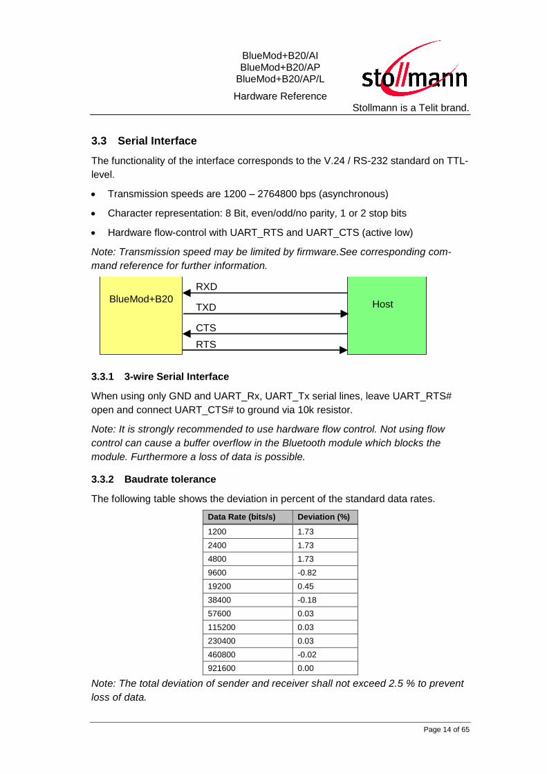
3.3 Serial Interface
The functionality of the interface corresponds to the V.24 / RS-232 standard on TTL-
level.
Transmission speeds are 1200 – 2764800 bps (asynchronous)
Character representation: 8 Bit, even/odd/no parity, 1 or 2 stop bits
Hardware flow-control with UART_RTS and UART_CTS (active low)
Note: Transmission speed may be limited by firmware.See corresponding com-
mand reference for further information.
BlueMod+B20
Host
RXD
TXD
CTS
RTS
3.3.1 3-wire Serial Interface
When using only GND and UART_Rx, UART_Tx serial lines, leave UART_RTS#
open and connect UART_CTS# to ground via 10k resistor.
Note: It is strongly recommended to use hardware flow control. Not using flow
control can cause a buffer overflow in the Bluetooth module which blocks the
module. Furthermore a loss of data is possible.
3.3.2 Baudrate tolerance
The following table shows the deviation in percent of the standard data rates.
Data Rate (bits/s) Deviation (%)
1200 1.73
2400 1.73
4800 1.73
9600 -0.82
19200 0.45
38400 -0.18
57600 0.03
115200 0.03
230400 0.03
460800 -0.02
921600 0.00
Note: The total deviation of sender and receiver shall not exceed 2.5 % to prevent
loss of data.

BlueMod+B20/AI BlueMod+B20/AP
BlueMod+B20/AP/L
Hardware Reference Stollmann is a Telit brand.
Page 15 of 65
3.4 PIO Interface
It is possible to use the programmable digital I/Os PIO[0:11] and the programmable
analog I/Os AIO[0:1] on the BlueMod+B20. Their behavior has to be defined project
specific in the firmware.
3.5 I2C Interface
PIO[8:6] can be used to form a master I2C interface. The interface is formed using
software to drive these lines. Therefore, it is suited only to relatively slow functions
i.e. EEPROM. 2.2
k
2.2
k
2.2
k
VCC
WP
SCL
SDA
A0
A1
A2
GND
10nF
VSUP
PIO[8]
PIO[6]
PIO[7]
Example EEPROM connection
The BlueMod+B20/AI, BlueMod+B20/AP/L and BlueMod+B20/AP interface directly
to EEPROM devices including the following:
Atmel AT24Cxxx
Catalyst CAT24WCxxx
Fairchild FM24Cxxx
Microchip 24AAxxx
Philips PCF8582C-2, PCF8594C-2, PCF8598C-2
Seiko 24Cxx, 24CSxx
Rohm BR24Cxx
ST M24C32, M24C64, M24128-B, M24256-B,M24512
3.6 Bluetooth radio Interface
The BlueMod+B20/AI presents an integrated ceramic antenna.
The BlueMod+B20/AP and BlueMod+B20/AP/L present no integrated ceramic
antenna, but provide a 50 RF interface.

BlueMod+B20/AI BlueMod+B20/AP
BlueMod+B20/AP/L
Hardware Reference Stollmann is a Telit brand.
Page 16 of 65
It is highly recommended that you follow the design rule given in the Telit Application
Note on Antenna design [2].
3.7 PCM Interface
PCM or Pulse Code Modulation is a sampling technique for digitising analogue
signals.
The PCM interface for voice applications is provided via the PCM_OUT, PCM_IN,
PCM_CLK and PCM_SYNC pins.
The PCM interface can act as master or as slave device.
In master mode, clock frequencies of 128kHz, 256kHz or 512kHz can be generated,
when using the internal 4MHz clock. In slave mode, clock frequencies up to
2048kHz are accepted.
The Frame Clock is 8kHz. Long and Short Frame Sync are supported.
BlueMod+B20/AI, BlueMod+B20/AP/L and BlueMod+B20/AP interface directly to
PCM audio devices including the following:
Qualcom MSM3000 series and MSM5000 series CDMA base band devices
OKI MSM7705 four channel A-law and µ-law codec
Motorola MC145481 8-bit A-law and µ-law codec
Motorola MC145483 13-bit linear codec
STW 5093 5094 14-bit linear codec

BlueMod+B20/AI BlueMod+B20/AP
BlueMod+B20/AP/L
Hardware Reference Stollmann is a Telit brand.
Page 17 of 65
3.8 USB Interface
3.8.1 D+, D-
BlueMod+B20/AI, BlueMod+B20/AP/L and BlueMod+B20/AP contain a full speed
USB version 1.1 compliant interface capable of directly driving an USB cable. The
BlueMod+B20 operates as an USB peripheral and responds to requests from an
USB master host controller.
3.8.2 USB Self-Powered Mode
In USB self-powered mode, the BlueMod+B20 is powered from its own power
supply and not from the USB Vbus line. In order to detect when the USB Vbus line is
powered up, the USB Vbus line is monitored by PIO4 through a voltage divider.
Rvb1
22k
Rs
27R
Rs
27R
Rpu1k5
Rvb247k
D+
D-
VBUS
GND
PIO2/USB-Pull_Up
USB_DP
USB_DN
PIO4/USB_ON
BlueMod+B20
Connections in self powered mode
VSUP
+3.3V
In self powered mode a 1.5KΩ pull up resistor needs to be connected between PIO2
and the USB D+ line. This pulls the USB D+ line high when the BlueMod+B20 is
ready for enumeration, signaling to the host controller that the BlueMod+B20 is a full
speed (12Mbps) USB device.
Note
The feature to detect USB attach/detach on PIO4 is not necessary for embedded designs where the
USB interface is permanently connected to a host CPU. Therefore it is not enabled in the
BlueMod+B20 FW by default. Please contact Telit if you want to use the USB attach/detach detection
feature.
BlueMod+B20/AI BlueMod+B20/AP
BlueMod+B20/AP/L
Hardware Reference Stollmann is a Telit brand.
Page 18 of 65
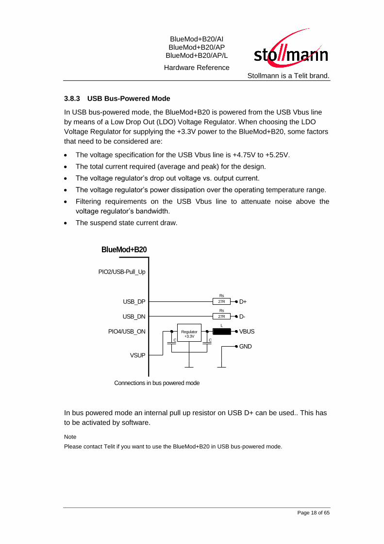
3.8.3 USB Bus-Powered Mode
In USB bus-powered mode, the BlueMod+B20 is powered from the USB Vbus line
by means of a Low Drop Out (LDO) Voltage Regulator. When choosing the LDO
Voltage Regulator for supplying the +3.3V power to the BlueMod+B20, some factors
that need to be considered are:
The voltage specification for the USB Vbus line is +4.75V to +5.25V.
The total current required (average and peak) for the design.
The voltage regulator’s drop out voltage vs. output current.
The voltage regulator’s power dissipation over the operating temperature range.
Filtering requirements on the USB Vbus line to attenuate noise above the
voltage regulator’s bandwidth.
The suspend state current draw.
PIO2/USB-Pull_Up
L
Rs
27R
Rs
27R D+
D-
VBUS
GND
USB_DP
USB_DN
PIO4/USB_ON
BlueMod+B20
VSUP
Regulator+3.3V
C C
Connections in bus powered mode
In bus powered mode an internal pull up resistor on USB D+ can be used.. This has
to be activated by software.
Note
Please contact Telit if you want to use the BlueMod+B20 in USB bus-powered mode.
BlueMod+B20/AI BlueMod+B20/AP
BlueMod+B20/AP/L
Hardware Reference Stollmann is a Telit brand.
Page 19 of 65
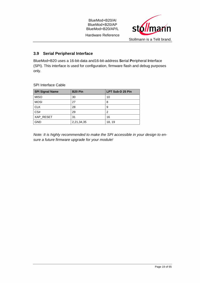
3.9 Serial Peripheral Interface
BlueMod+B20 uses a 16-bit-data and16-bit-address Serial Peripheral Interface
(SPI). This interface is used for configuration, firmware flash and debug purposes
only.
SPI Interface Cable
SPI Signal Name B20 Pin LPT Sub-D 25 Pin
MISO 30 10
MOSI 27 8
CLK 28 9
CS# 29 2
XAP_RESET 31 16
GND 2,21,34,35 18, 19
Note: It is highly recommended to make the SPI accessible in your design to en-
sure a future firmware upgrade for your module!

BlueMod+B20/AI BlueMod+B20/AP
BlueMod+B20/AP/L
Hardware Reference Stollmann is a Telit brand.
Page 20 of 65
4 Pin Description
4.1 Pin Numbering
1 ANT
2 GND3 PIO04 PIO15 PIO26 PIO37 PIO48 PIO59 PIO610 PIO711 PIO812 PIO913 PIO1014 PIO11
GND 34AIO1 33AIO0 32
RESET# 31SPI_MISO 30
SPI_CS# 29SPI_CLK 28
SPI_MOSI 27UART_CTS# 26
UART_TX 25UART_RTS# 24
UART_RX 23VSUP 22GND 21
US
B_D
N 1
5U
SB
_D
P 1
6P
CM
_C
LK
17
PC
M_O
UT 1
8P
CM
_IN
19
PC
M_S
YN
C 2
035 GND
Figure 4.1 BlueMod+B20/AI, BlueMod+B20/AP/L Pin Numbering
BlueMod+B20/AI BlueMod+B20/AP
BlueMod+B20/AP/L
Hardware Reference Stollmann is a Telit brand.
Page 21 of 65
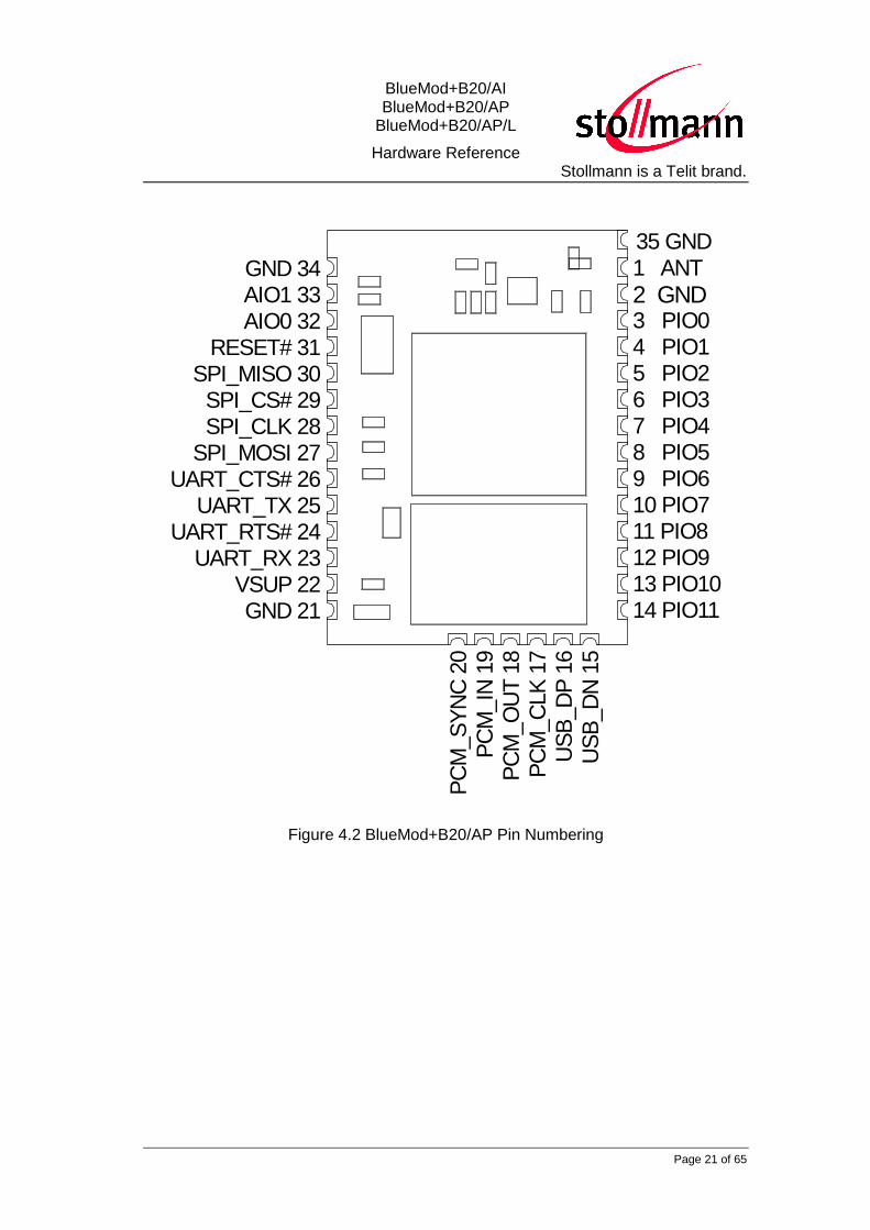
1 ANT
2 GND3 PIO04 PIO15 PIO26 PIO37 PIO48 PIO59 PIO610 PIO711 PIO812 PIO913 PIO1014 PIO11
GND 34AIO1 33AIO0 32
RESET# 31SPI_MISO 30
SPI_CS# 29SPI_CLK 28
SPI_MOSI 27UART_CTS# 26
UART_TX 25UART_RTS# 24
UART_RX 23VSUP 22GND 21
US
B_D
N 1
5U
SB
_D
P 1
6P
CM
_C
LK
17
PC
M_O
UT 1
8P
CM
_IN
19
PC
M_S
YN
C 2
0
35 GND
Figure 4.2 BlueMod+B20/AP Pin Numbering
BlueMod+B20/AI BlueMod+B20/AP
BlueMod+B20/AP/L
Hardware Reference Stollmann is a Telit brand.
Page 22 of 65
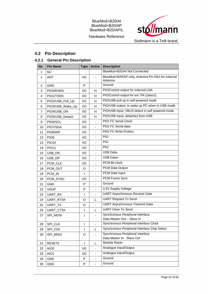
4.2 Pin Description
4.2.1 General Pin Description
No Pin Name Type Active Description
1 NC BlueMod+B20/AI Not Connected
1 ANT I/O - BlueMod+B20/AP only, Antenna Pin 50 for external Antenna
2 GND P - Ground
3 PIO0/RXEN I/O H PIO/Control output for external LNA
4 PIO1/TXEN I/O H PIO/Control output for ext. PA (class1)
5 PIO2/USB_Pull_Up I/O H PIO/USB pull up in self powered mode
6 PIO3/USB_Wake_Up I/O H PIO/USB output, to wake up PC when in USB mode
7 PIO4/USB_ON I/O H PIO/USB input, VBUS detect in self powered mode
8 PIO5/USB_Detach I/O H PIO/USB input, detaches from USB
9 PIO6/SCL I/O - PIO/ I2C Serial Clock
10 PIO7/SDA I/O - PIO/ I2C Serial data
11 PIO8/WP I/O - PIO/ I2C Write Protect
12 PIO9 I/O - PIO
13 PIO10 I/O - PIO
14 PIO11 I/O - PIO
15 USB_DN I/O - USB Data-
16 USB_DP I/O - USB Data+
17 PCM_CLK I/O - PCM Bit clock
18 PCM_OUT O - PCM Data Output
19 PCM_IN I - PCM Data Input
20 PCM_SYNC I/O - PCM Frame Sync
21 GND P - Ground
22 VSUP P - 3.3V Supply Voltage
23 UART_RX I - UART Asynchronous Receive Data
24 UART_RTS# O L UART Request To Send
25 UART_TX O - UART Asynchronous Transmit Data
26 UART_CTS# I L UART Clear To Send
27 SPI_MOSI I - Synchronous Peripheral Interface
Data Master Out – Slave In
28 SPI_CLK I - Synchronous Peripheral Interface Clock
29 SPI_CS# I L Synchronous Peripheral Interface Chip Select
30 SPI_MISO O - Synchronous Peripheral Interface
Data Master In- Slave Out
31 RESET# I L Module Reset
32 AIO0 I/O - Analogue Input/Output
33 AIO1 I/O - Analogue Input/Output
34 GND P - Ground
35 GND P - Ground

BlueMod+B20/AI BlueMod+B20/AP
BlueMod+B20/AP/L
Hardware Reference Stollmann is a Telit brand.
Page 23 of 65
Type: PU - Pulled up; PD – pulled down; P – Power; I – Input; O – Output; I/O - bidirectional

BlueMod+B20/AI BlueMod+B20/AP
BlueMod+B20/AP/L
Hardware Reference Stollmann is a Telit brand.
Page 24 of 65
4.2.2 Application Specific Pin Description
4.2.2.1 SPP Pin Configuration DCE Mode
No Pin name Pin function Type Active Description
1 NC NC BlueMod+B20/AI Not Connected
1 ANT ANT I/O BlueMod+B20/AP only, Antenna Pin 50 for external Antenna
2 GND GND P - Ground
3 PIO0 reserved I-PU - Leave open
4 PIO1 reserved I-PU - Leave open
5 PIO2 LED1# O L Status LED 1 “Bluetooth connected” flashes when a Bluetooth link is established Use or leave open
6 PIO3 DCD# O L Data Carrier Detect Output Use or leave open
7 PIO4 RTC-IN# I-PD L DTR – Data Terminal Ready Use or leave open
8 PIO5 RTC-OUT# O L DSR – Data Set Ready; Use or leave open
9 PIO6 RI# or SCL1 O L RING Output or I2C Serial Clock Use or leave open In case of I2C Serial Clock 2.2k Pull-up
10 PIO7 SDA 1 I/O-PU - I2C Serial Data Use or leave open In case of I2C Serial Data 2.2k Pull-up
11 PIO8 WP 1 O - I2C Write Protect Use or leave open In case of I2C Write Protect 2.2k Pull-up
12 PIO9 reserved O Leave open
13 PIO10 reserved O Leave open
14 PIO11 reserved I-PU Leave open
15 USB_DN reserved I-PD - Leave open
16 USB_DP reserved I-PD - Leave open
17 PCM_CLK reserved I-PD - Leave open
18 PCM_OUT reserved O - Leave open
19 PCM_IN reserved I-PD - Leave open
20 PCM_SYNC reserved I-PD - Leave open
21 GND GND P - Ground
22 VSUP VSUP P - 3.3V Supply Voltage
23 UART_RX UART_RX I-PD - UART Asynchronous Receive Data
24 UART_RTS# UART_RTS# O L UART Request To Send Use for flow control
25 UART_TX UART_TX O - UART Asynchronous Transmit Data
26 UART_CTS# UART_CTS# I-PD L UART Clear To Send Use for flow control
27 SPI_MOSI SPI_MOSI I-PD - SPI Data Input Connector, Test-Point for FW-FLASH
1 subject to firmware support, contact Telit for current status.

BlueMod+B20/AI BlueMod+B20/AP
BlueMod+B20/AP/L
Hardware Reference Stollmann is a Telit brand.
Page 25 of 65
28 SPI_CLK SPI_CLK I-PD - SPI Clock Connector, Test-Point for FW-FLASH
29 SPI_CS# SPI_CS# I-PU L SPI Chip Select Input Connector, Test-Point for FW-FLASH
30 SPI_MISO SPI_MISO O SPI Data Output Connector, Test-Point for FW-FLASH
31 RESET# RESET# I-PU L Module Reset Connect to RESET Controller
34 GND GND P - Ground
35 GND GND P - Ground

BlueMod+B20/AI BlueMod+B20/AP
BlueMod+B20/AP/L
Hardware Reference Stollmann is a Telit brand.
Page 26 of 65
4.2.2.2 SPP Pin Configuration DTE Mode
No Pin Name Pin Function Type Active Description
1 NC NC BlueMod+B20/AI Not Connected
1 ANT ANT I/O BlueMod+B20/AP only, Antenna Pin 50 for external Antenna
2 GND GND P - Ground
3 PIO0 reserved I-PU - Leave open
4 PIO1 reserved I-PU - Leave open
5 PIO2 LED1# O L Status LED 1 “Bluetooth connected” flashes when a Bluetooth link is established Use or leave open
6 PIO3 DCD# I-PD L Data Carrier Detect Input Use or leave open
7 PIO4 RTC-IN# I-PD L DSR – Data Set Ready Use or leave open
8 PIO5 RTC-OUT# O L DTR – Data Terminal Ready Use or leave open
9 PIO6 RI# or SCL 2 I-PU L RING Input in DTE mode or I2C Serial Clock In case of I2C Serial Clock 2.2k Pull-up
10 PIO7 SDA 2 I/O-PU
- I2C Serial Data Use or leave open In case of I2C Serial Data 2.2k Pull-up
11 PIO8 WP 2 O - I2C Write Protect Use or leave open In case of I2C Write Protect 2.2k Pull-up
12 PIO9 reserved O Leave open
13 PIO10 reserved O Leave open
14 PIO11 reserved I-PU Leave open
15 USB_DN reserved I-PD - Leave open
16 USB_DP reserved I-PD - Leave open
17 PCM_CLK reserved IPD - Leave open
18 PCM_OUT reserved O - Leave open
19 PCM_IN reserved I-PD - Leave open
20 PCM_SYNC reserved I-PD - Leave open
21 GND GND P - Ground
22 VSUP VSUP P - 3.3V Supply Voltage
23 UART_RX UART_RX I-PD - UART Asynchronous Receive Data
24 UART_RTS# UART_RTS# O L UART Request To Send Use for flow control
25 UART_TX UART_TX O - UART Asynchronous Transmit Data
26 UART_CTS# UART_CTS# I-PD L UART Clear To Send Use for flow control
27 SPI_MOSI SPI_MOSI I-PD - SPI Data Input Connector, Test-Point for FW-FLASH, PSTOOLS
28 SPI_CLK SPI_CLK I-PD - SPI Clock Connector, Test-Point for FW-FLASH, PSTOOLS
2 subject to firmware support, contact Telit for current status.

BlueMod+B20/AI BlueMod+B20/AP
BlueMod+B20/AP/L
Hardware Reference Stollmann is a Telit brand.
Page 27 of 65
29 SPI_CS# SPI_CS# I-PU L SPI Chip Select Input Connector, Test-Point for FW-FLASH, PSTOOLS
30 SPI_MISO SPI_MISO O SPI Data Output Connector, Test-Point for FW-FLASH, PSTOOLS
31 RESET# RESET# I-PU L Module Reset Connect to RESET Controller
34 GND GND P - Ground
35 GND GND P - Ground
.
BlueMod+B20/AI BlueMod+B20/AP
BlueMod+B20/AP/L
Hardware Reference Stollmann is a Telit brand.
Page 28 of 65
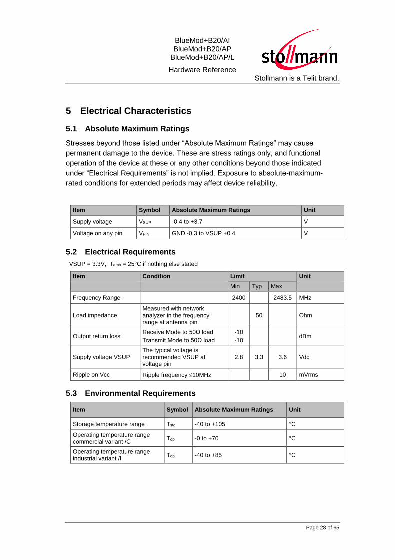
5 Electrical Characteristics
5.1 Absolute Maximum Ratings
Stresses beyond those listed under “Absolute Maximum Ratings” may cause
permanent damage to the device. These are stress ratings only, and functional
operation of the device at these or any other conditions beyond those indicated
under “Electrical Requirements” is not implied. Exposure to absolute-maximum-
rated conditions for extended periods may affect device reliability.
Item Symbol Absolute Maximum Ratings Unit
Supply voltage VSUP -0.4 to +3.7 V
Voltage on any pin VPin GND -0.3 to VSUP +0.4 V
5.2 Electrical Requirements
VSUP = 3.3V, Tamb = 25°C if nothing else stated
Item Condition Limit Unit
Min Typ Max
Frequency Range 2400 2483.5 MHz
Load impedance Measured with network analyzer in the frequency range at antenna pin
50 Ohm
Output return loss Receive Mode to 50Ω load
Transmit Mode to 50Ω load
-10
-10 dBm
Supply voltage VSUP The typical voltage is recommended VSUP at voltage pin
2.8 3.3 3.6 Vdc
Ripple on Vcc Ripple frequency 10MHz 10 mVrms
5.3 Environmental Requirements
Item Symbol Absolute Maximum Ratings Unit
Storage temperature range Tstg -40 to +105 °C
Operating temperature range commercial variant /C
Top -0 to +70 °C
Operating temperature range industrial variant /I
Top -40 to +85 °C

BlueMod+B20/AI BlueMod+B20/AP
BlueMod+B20/AP/L
Hardware Reference Stollmann is a Telit brand.
Page 29 of 65
5.4 Digital I/O including RESET#
VSUP = 3.3V, Tamb = 25°C
Symbol Item Condition Limit Unit
Min Typ Max
VIL Low-Level Input Voltage VSUP = 3.3V - 0.4 - 0.8 V
VIH High-Level Input Voltage 0.7xVSUP - - V
VOL Low-Level Output Voltage
IOL = 4mA - -
0.2 V
VOH High-Level Output Voltage
IOH = -4mA VSUP-0.2 -
- V
IOL Low -Level Output Current
VOL = 0.55V - -
4 mA
IOH High-Level Output Current
VOH = 2.3V /100k PU
VOH = 2.3V /10k PU
-
-
-4 mA
Isp-u Input-current Strong pull-up -100 -40 -10 A
Isp-d Input-current Strong pull-down +10 +40 -+100 A
Iwp-u Input-current Weak pull-up -5.0 -1.0 -0.2 A
Iwp-d Input-current Weak pull-down +0.2 -1.0 +5.0 A
Ilc I/O pad leakage current -1 0 +1 A
Cl Input Capacitance 1.0 - 5.0 pF
5.5 AIO-Interface
VSUP = 3.3V, Tamb = 25°C
Item Limit Unit
Min Typ Max
Resolution - - 8 Bits
Input voltage range 0 1.7 V
Accuracy -1 1 LSB
Offset -1 1 LSB
Gain error -0.8 0.8 %
Input bandwidth 100 kHz
Conversion time - 2.5 - µs
Sample rate 700 Samples/s
BlueMod+B20/AI BlueMod+B20/AP
BlueMod+B20/AP/L
Hardware Reference Stollmann is a Telit brand.
Page 30 of 65
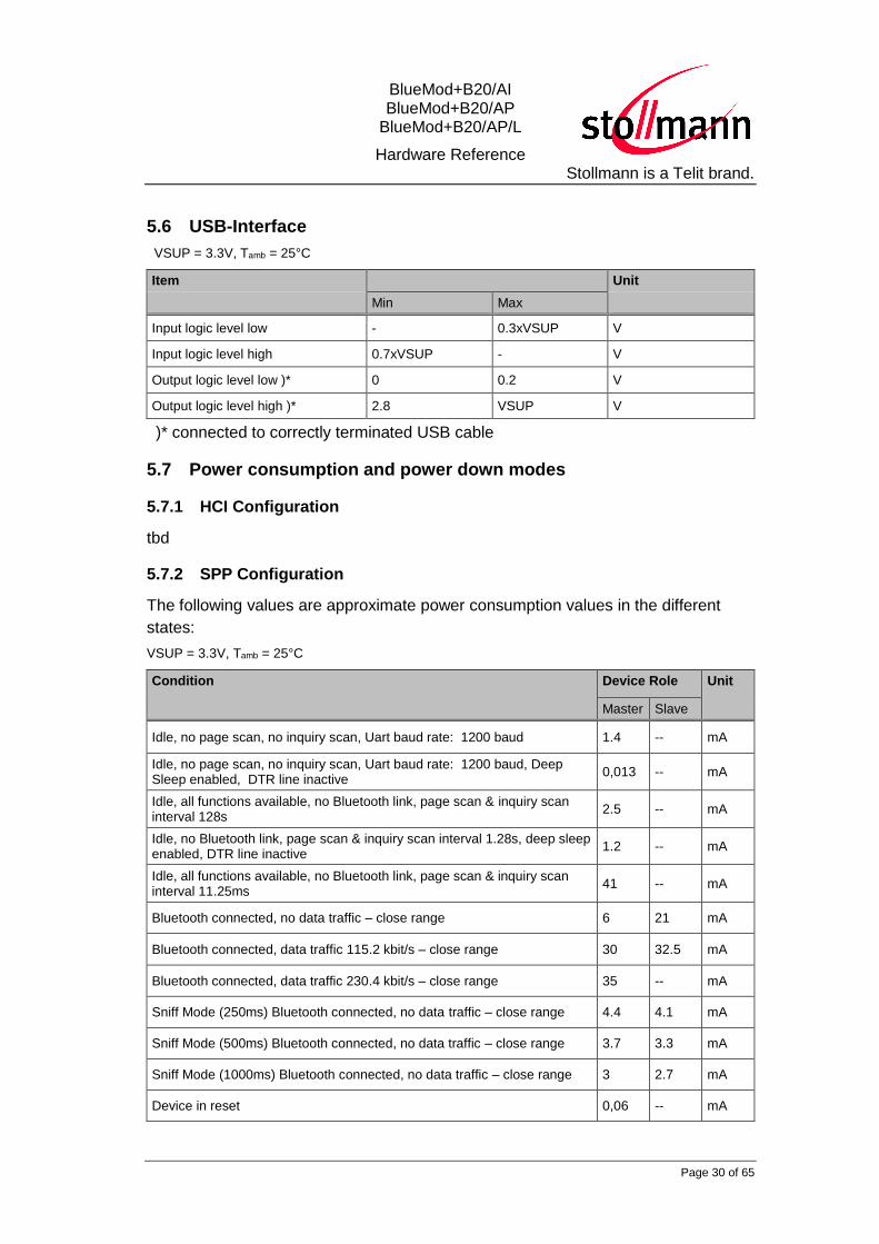
5.6 USB-Interface
VSUP = 3.3V, Tamb = 25°C
Item Unit
Min Max
Input logic level low - 0.3xVSUP V
Input logic level high 0.7xVSUP - V
Output logic level low )* 0 0.2 V
Output logic level high )* 2.8 VSUP V
)* connected to correctly terminated USB cable
5.7 Power consumption and power down modes
5.7.1 HCI Configuration
tbd
5.7.2 SPP Configuration
The following values are approximate power consumption values in the different
states:
VSUP = 3.3V, Tamb = 25°C
Condition Device Role Unit
Master Slave
Idle, no page scan, no inquiry scan, Uart baud rate: 1200 baud 1.4 -- mA
Idle, no page scan, no inquiry scan, Uart baud rate: 1200 baud, Deep Sleep enabled, DTR line inactive
0,013 -- mA
Idle, all functions available, no Bluetooth link, page scan & inquiry scan interval 128s
2.5 -- mA
Idle, no Bluetooth link, page scan & inquiry scan interval 1.28s, deep sleep enabled, DTR line inactive
1.2 -- mA
Idle, all functions available, no Bluetooth link, page scan & inquiry scan interval 11.25ms
41 -- mA
Bluetooth connected, no data traffic – close range 6 21 mA
Bluetooth connected, data traffic 115.2 kbit/s – close range 30 32.5 mA
Bluetooth connected, data traffic 230.4 kbit/s – close range 35 -- mA
Sniff Mode (250ms) Bluetooth connected, no data traffic – close range 4.4 4.1 mA
Sniff Mode (500ms) Bluetooth connected, no data traffic – close range 3.7 3.3 mA
Sniff Mode (1000ms) Bluetooth connected, no data traffic – close range 3 2.7 mA
Device in reset 0,06 -- mA
BlueMod+B20/AI BlueMod+B20/AP
BlueMod+B20/AP/L
Hardware Reference Stollmann is a Telit brand.
Page 31 of 65
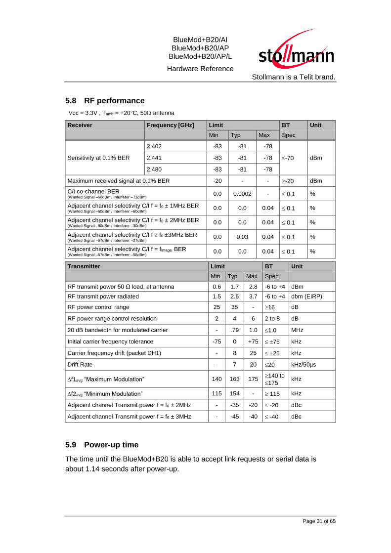
5.8 RF performance
Vcc = 3.3V , Tamb = +20°C, 50 antenna
Receiver Frequency [GHz] Limit BT Unit
Min Typ Max Spec
Sensitivity at 0.1% BER
2.402 -83 -81 -78
-70 dBm 2.441 -83 -81 -78
2.480 -83 -81 -78
Maximum received signal at 0.1% BER -20 - - -20 dBm
C/I co-channel BER (Wanted Signal –60dBm / Interferer –71dBm)
0.0 0.0002 - 0.1 %
Adjacent channel selectivity C/I f = f0 ± 1MHz BER (Wanted Signal –60dBm / Interferer –60dBm) 0.0 0.0 0.04 0.1 %
Adjacent channel selectivity C/I f = f0 ± 2MHz BER (Wanted Signal –60dBm / Interferer –30dBm) 0.0 0.0 0.04 0.1 %
Adjacent channel selectivity C/I f f0 ±3MHz BER (Wanted Signal –67dBm / Interferer –27dBm)
0.0 0.03 0.04 0.1 %
Adjacent channel selectivity C/I f = fimage BER (Wanted Signal –67dBm / Interferer –58dBm) 0.0 0.0 0.04 0.1 %
Transmitter Limit BT Unit
Min Typ Max Spec
RF transmit power 50 Ω load, at antenna 0.6 1.7 2.8 -6 to +4 dBm
RF transmit power radiated 1.5 2.6 3.7 -6 to +4 dbm (EIRP)
RF power control range 25 35 - 16 dB
RF power range control resolution 2 4 6 2 to 8 dB
20 dB bandwidth for modulated carrier - .79 1.0 1.0 MHz
Initial carrier frequency tolerance -75 0 +75 75 kHz
Carrier frequency drift (packet DH1) - 8 25 25 kHz
Drift Rate - 7 20 20 kHz/50µs
f1avg “Maximum Modulation” 140 163 175 140 to
175 kHz
f2avg “Minimum Modulation” 115 154 - 115 kHz
Adjacent channel Transmit power f = f0 ± 2MHz - -35 -20 -20 dBc
Adjacent channel Transmit power f = f0 ± 3MHz - -45 -40 -40 dBc
5.9 Power-up time
The time until the BlueMod+B20 is able to accept link requests or serial data is
about 1.14 seconds after power-up.

BlueMod+B20/AI BlueMod+B20/AP
BlueMod+B20/AP/L
Hardware Reference Stollmann is a Telit brand.
Page 32 of 65
6 Mechanical Characteristics
6.1 Dimensions
14,5
28
0,8+0,1
-0,1
2,7+0,1
-0,1
2,0+0,1
-0,1
Figure 6.1 BlueMod+B20/AI and BlueMod+B20/AP/L dimensions
BlueMod+B20/AI BlueMod+B20/AP
BlueMod+B20/AP/L
Hardware Reference Stollmann is a Telit brand.
Page 33 of 65
20,0
14,5
0,8+0,1
-0,1
2,0+0,1
-0,1
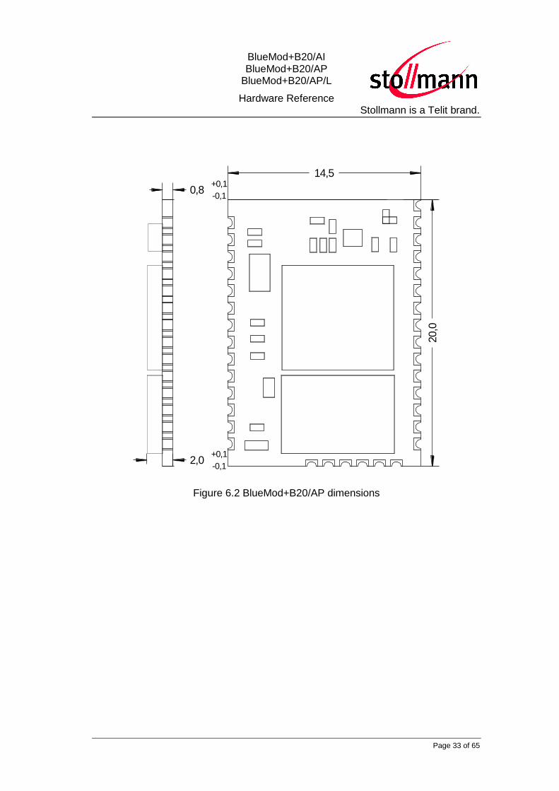
Figure 6.2 BlueMod+B20/AP dimensions

BlueMod+B20/AI BlueMod+B20/AP
BlueMod+B20/AP/L
Hardware Reference Stollmann is a Telit brand.
Page 34 of 65
6.2 Recommended Land Pattern
BlueMod+B20/AItop view
2,7
3,5
14,5
16,5
8
1,2
75
1,275
28
15,1
1,3
1,3
0,9
1,6
75
0,3
0,3
1,825
Figure 6.3 BlueMod+B20/AI and BlueMod+B20/AP/L land pattern

BlueMod+B20/AI BlueMod+B20/AP
BlueMod+B20/AP/L
Hardware Reference Stollmann is a Telit brand.
Page 35 of 65
BlueMod+B20/APtop view
2,7
3,5
14,5
16,5
8
1,2
75
1,275
15,1
1,3
1,3
0,9
1,6
75
0,3
0,3
1,825
20,0
Figure 6.4 BlueMod+B20/AP land pattern

BlueMod+B20/AI BlueMod+B20/AP
BlueMod+B20/AP/L
Hardware Reference Stollmann is a Telit brand.
Page 36 of 65
6.3 Re-flow Temperature-Time Profile
The data here is given only for guidance on solder and has to be adopted to your
process and other re-flow parameters for example the used solder paste. The paste
manufacturer provides a re-flow profile recommendation for his product.
Our used temp. profile
for reflow soldering
Temp.[°C]
Time [s]
230°C -250°C max.
220°C
150°C – 190°C
90 30s
30 +20/-10s
Opposite side re-flow is prohibited due to module weight.
Devices will withstand the specified profile and will withstand up to 2 re-flows to a
maximum temperature of 260°C.

BlueMod+B20/AI BlueMod+B20/AP
BlueMod+B20/AP/L
Hardware Reference Stollmann is a Telit brand.
Page 37 of 65
6.4 Restricted Area
The mother board should have no bare conductors or vias in this restricted area,
because it is not covered by stop mask print. Also no copper (planes, traces or vias)
are allowed in this area , because of mismatching the on-board antenna.
BlueMod+B20top view
Restricted Area
2,7
3,5
8,1
14,5
Figure 6.5 BlueMod+B20/AI Restricted Area

BlueMod+B20/AI BlueMod+B20/AP
BlueMod+B20/AP/L
Hardware Reference Stollmann is a Telit brand.
Page 38 of 65
BlueMod+B20/APtop view
Restricted Area
2,7
3,5
Figure 6.6 BlueMod+B20/AP/L Restricted Area
6.5 Housing Guidelines
The individual case must be checked to decide whether a specific housing is
suitable for the use of the internal antenna. A plastic housing must at least fulfill the
following requirements:
Non-conductive material, non-RF-blocking plastics
No metallic coating
ABS is suggested
BlueMod+B20/AI BlueMod+B20/AP
BlueMod+B20/AP/L
Hardware Reference Stollmann is a Telit brand.
Page 39 of 65
6.6 Antenna Issues
BlueMod+B20 is shipped with 2 different antenna designs:
BlueMod+B20/AI comprises a ceramic antenna which as a component is
soldered to the circuit board. This is functional for a BlueMod+B20/AI integrated
into a plastic housing. No additional antenna is required.
For an external antenna to be set in, e.g. because the BlueMod+B20 is integrated
into a metal housing, the ceramic antenna is replaced.
BlueMod+B20/AP routes the antenna signal to pin 1.
The gain of the external antenna shall not exceed +2dBi.
When using an external Antenna the. The FCC/IC rules do require either using a
fixed mounted antenna or the use of an unique connector in order to prevent misuse
by the end user mounting antennas with higher gain.
The performance of the internal antenna respectively the external antenna has in
any case to be checked within the final integration environment. Adjacent PCBs,
components, cables, housings etc. could otherwise influence the radiation pattern or
be influenced by the radio wave energy.
It must be ensured that the antenna is not co-located or operating in conjunction
with any other antennas, transmitters, cables or connectors. When the internal
ceramic antenna is used, certain restrictions are to be considered.

BlueMod+B20/AI BlueMod+B20/AP
BlueMod+B20/AP/L
Hardware Reference Stollmann is a Telit brand.
Page 40 of 65
20,0 mm
20,0 mm
20,0 mm
Ante
nna
Figure 6.7 Antenna – recommended restricted area
To give an optimized antenna performance the restricted area having no ground or
power planes, traces or parts should be widened. The following dimensions should
be implemented, depending on your possible space.
BlueMod+B20/AI BlueMod+B20/AP
BlueMod+B20/AP/L
Hardware Reference Stollmann is a Telit brand.
Page 41 of 65
20,0 mm
20,0 mm
20,0 mm
Ante
nna
target PCB
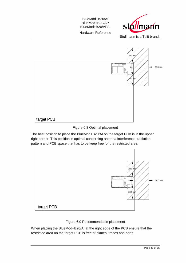
Figure 6.8 Optimal placement
The best position to place the BlueMod+B20/AI on the target PCB is in the upper
right corner. This position is optimal concerning antenna interference; radiation
pattern and PCB space that has to be keep free for the restricted area.
20,0 mm
20,0 mm
20,0 mm
Ante
nna
target PCB
Figure 6.9 Recommendable placement
When placing the BlueMod+B20/AI at the right edge of the PCB ensure that the
restricted area on the target PCB is free of planes, traces and parts.

BlueMod+B20/AI BlueMod+B20/AP
BlueMod+B20/AP/L
Hardware Reference Stollmann is a Telit brand.
Page 42 of 65
20,0 mm
20,0 mm
20,0 mmA
nte
nna
target PCB
Figure 6.10 Acceptable, but not optimal placement
When placing the BlueMod+B20/AI on other positions than the right side the
complete restricted area should be kept free of planes, traces and parts.
6.7 Safety Guidelines
According to SAR regulation EN 62479: 2010 the BlueMod+B20/AI,
BlueMod+B20/AP/L and BlueMod+B20/AP are not intended to be used in close
proximity to the human body. Please refer to above-mentioned regulation for more
specific information.
In respect to the safety regulation EN 60950-1: 2006 all conductive parts of the
BlueMod+B20/AI, BlueMod+B20/AP/L and BlueMod+B20/AP are to be classified as
SELV circuitry. OEM’s implementing the BlueMod+B20in their products should
follow the isolation rules given in regulation EN 60950-1: 2006.
The PCB material of the BlueMod+B20/AI, BlueMod+B20/AP/L and
BlueMod+B20/AP are classified UL-94V0.

BlueMod+B20/AI BlueMod+B20/AP
BlueMod+B20/AP/L
Hardware Reference Stollmann is a Telit brand.
Page 43 of 65
7 Approvals/Certifications
7.1 Declaration of conformity CE RED

BlueMod+B20/AI BlueMod+B20/AP
BlueMod+B20/AP/L
Hardware Reference Stollmann is a Telit brand.
Page 44 of 65
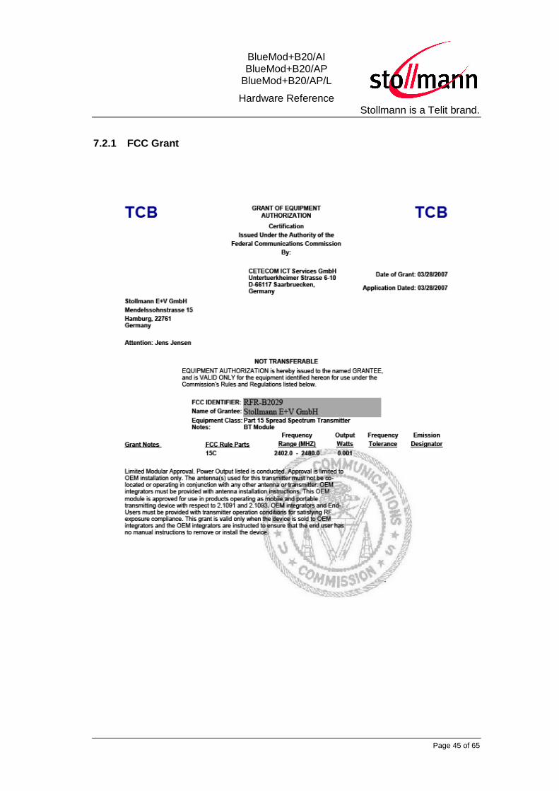
7.2 FCC/IC Compliance
The BlueMod+B20 has been tested to fulfill the FCC and IC requirements. Test
reports are available on request.
Please note that the FCC and IC grants are only valid for the variants using the
internal ceramic antenna, denoted by the string “AI” in the product name.
BlueMod+B20 modules designed for the use with an external antenna,
denoted by the string “AP” in the product name, do need extra procedures.
Every new antenna configuration requires a FCC/IC class 2 permissive change
(C2PC). For using another antenna with variant BlueMod+B20/AP, please contact
Telit for starting the FCC/IC C2PC process. Costs for re-measurements and TCB
certification should be considered.
BlueMod+B20/AI BlueMod+B20/AP
BlueMod+B20/AP/L
Hardware Reference Stollmann is a Telit brand.
Page 45 of 65
7.2.1 FCC Grant

BlueMod+B20/AI BlueMod+B20/AP
BlueMod+B20/AP/L
Hardware Reference Stollmann is a Telit brand.
Page 46 of 65
7.2.2 IC Grant
BlueMod+B20/AI BlueMod+B20/AP
BlueMod+B20/AP/L
Hardware Reference Stollmann is a Telit brand.
Page 47 of 65
7.2.3 FCC/IC Statement
This device complies with Part 15 of the FCC Rules and with RSS-210 of Industry
Canada.
Operation is subject to the following two conditions:
(1) this device my not cause harmful interference, and
(2) this device must accept any interference received, including interference
that may cause undesired operation.
7.2.4 Caution
Warning: Changes or modifications made to this equipment not expressly approved
by Telit may void the FCC authorization to operate this equipment.
7.2.5 FCC Warning
This equipment has been tested and found to comply with the limits for a Class B
digital device, pursuant to Part 15 of the FCC Rules. These limits are designed to
provide reasonable protection against harmful interference in a residential
installation. This equipment generates, uses and can radiate radio frequency energy
and, if not installed and used in accordance with the instructions, may cause harmful
interference to radio communications. However, there is no guarantee that
interference will not occur in a particular installation. If this equipment does cause
harmful interference to radio or television reception, which can be determined by
turning the equipment off and on, the user is encouraged to try to correct the
interference by one or more of the following measures:
Reorient or relocate the receiving antenna.
Increase the separation between the equipment and receiver.
Connect the equipment into an outlet on a circuit different from that to which the
receiver is connected.
Consult the dealer or an experienced radio/TV technician for help.
7.2.6 RF-exposure Statement
The BlueMod+B20 contains a portable modular transmitter. The max. output power
of 10mW is well below the FCC limit of 60mW/f(GHZ) = 60mW/2,4 = 25mW.
Therefore no restrictions apply for the use of the BlueMod+B20 close to the human
body.
BlueMod+B20/AI BlueMod+B20/AP
BlueMod+B20/AP/L
Hardware Reference Stollmann is a Telit brand.
Page 48 of 65
7.2.7 Labeling requirements for the End Product
Any End Product integrating the BlueMod+B20 must be labeled with at least the
following information:
This device contains transmitter with
FCC-ID: RFR-B2029
IC: 4957A-B2029
7.3 Japanese Certification
The BlueMod+B20 has been tested to fulfill the Japanese requirements.
Please note that the Japanese Certificates are only valid for the variants using
the internal ceramic antenna, denoted by the string “AI” in the product name.
BlueMod+B20 modules designed for the use with an external antenna,
denoted by the string “AP” in the product name, do need extra procedures.
Every new antenna configuration requires an administrative Japanese Re-
certification with reduced costs. For using another antenna with variant
BlueMod+B20/AP, please contact Telit for starting the Japanese administrative
process. Costs for re-measurements and certification should be considered.
BlueMod+B20/AI BlueMod+B20/AP
BlueMod+B20/AP/L
Hardware Reference Stollmann is a Telit brand.
Page 49 of 65
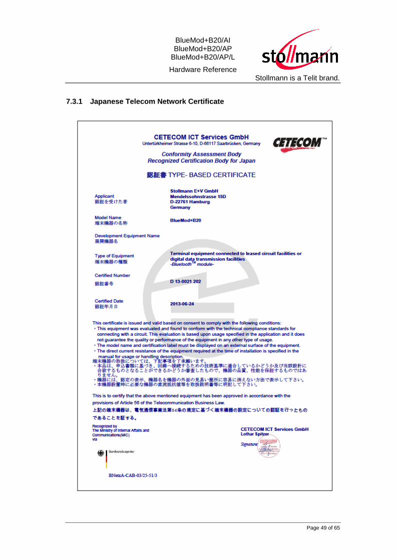
7.3.1 Japanese Telecom Network Certificate

BlueMod+B20/AI BlueMod+B20/AP
BlueMod+B20/AP/L
Hardware Reference Stollmann is a Telit brand.
Page 50 of 65
7.3.2 Japanese Radio Certificate
BlueMod+B20/AI BlueMod+B20/AP
BlueMod+B20/AP/L
Hardware Reference Stollmann is a Telit brand.
Page 51 of 65
7.4 Bluetooth Qualification
The BlueMod+B20 is a qualified design according to the Bluetooth Qualification
Program Reference Document (PRD) V2.3.
For further information about marking requirements of your product attention should
be paid the Bluetooth Brand Usage Guide at
https://www.bluetooth.org/en-us/bluetooth-brand/bluetooth-brand
According to the Bluetooth SIG rules (Bluetooth Declaration Process Document -
DPD) you must complete a Product Listing and Declaration of Compliance (DoC)
referencing the Qualified Design (QDID) for your product. For further information see
www.Bluetooth.org or contact Telit.
For the BlueMod+B20 are 3 different Qualified Design ID’s available, depending on
the implemented Bluetooth specification version and supported profiles.
All 3 Qualified Design ID’s are valid for variants /AI, internal antenna, and /AP,
external antenna, as long as the external antenna has a gain < +2dBi.

BlueMod+B20/AI BlueMod+B20/AP
BlueMod+B20/AP/L
Hardware Reference Stollmann is a Telit brand.
Page 52 of 65
7.4.1 BlueMod+B20 with BT 2.0+ EDR supporting SPP profile
The Declaration ID is:
B011904
The Qualified Design ID is:
2327
BlueMod+B20/AI BlueMod+B20/AP
BlueMod+B20/AP/L
Hardware Reference Stollmann is a Telit brand.
Page 53 of 65
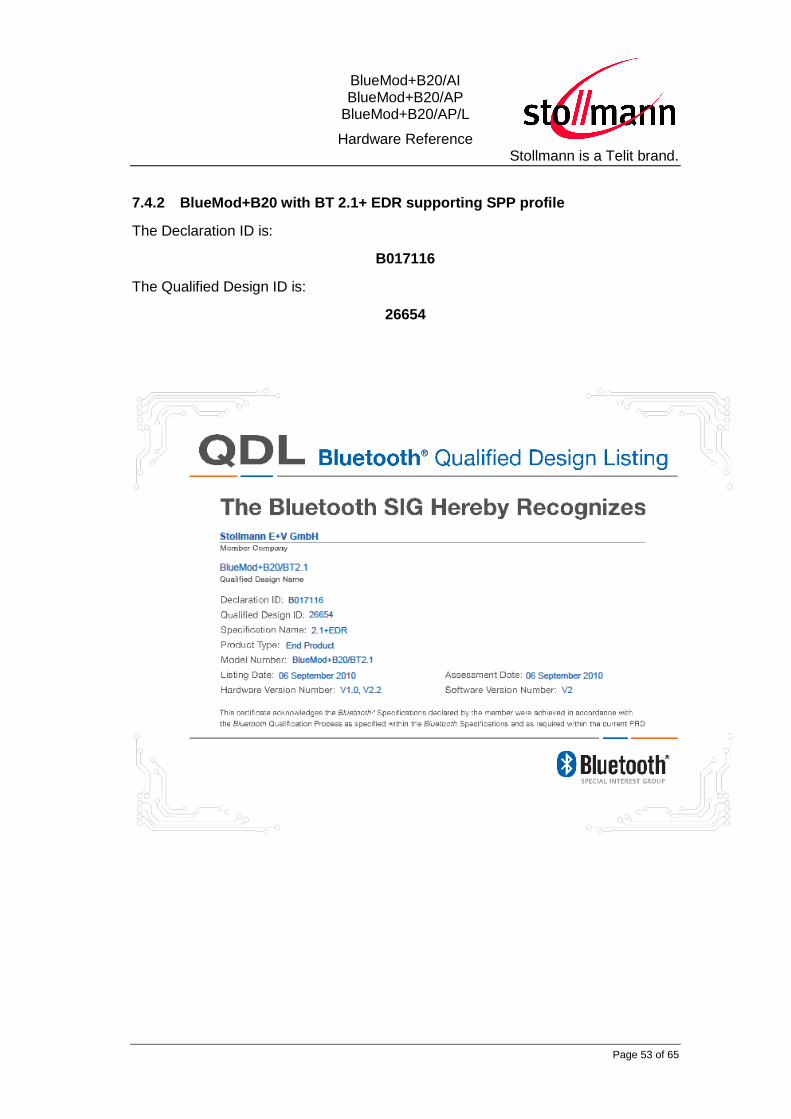
7.4.2 BlueMod+B20 with BT 2.1+ EDR supporting SPP profile
The Declaration ID is:
B017116
The Qualified Design ID is:
26654

BlueMod+B20/AI BlueMod+B20/AP
BlueMod+B20/AP/L
Hardware Reference Stollmann is a Telit brand.
Page 54 of 65
7.4.3 BlueMod+B20 with BT 2.1+ EDR supporting SPP,HID,OPP profile
The Declaration ID is:
B019003
The Qualified Design ID is:
33041
BlueMod+B20/AI BlueMod+B20/AP
BlueMod+B20/AP/L
Hardware Reference Stollmann is a Telit brand.
Page 55 of 65
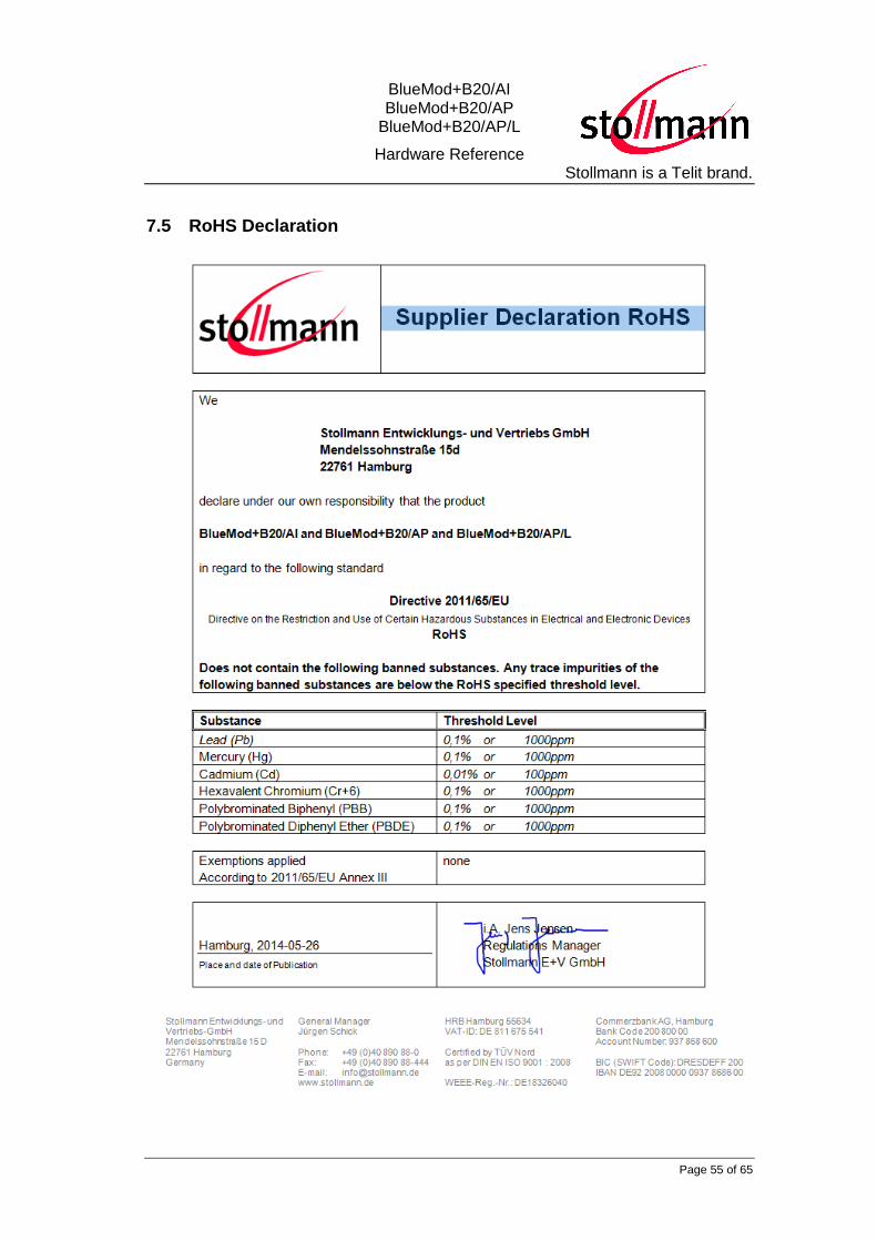
7.5 RoHS Declaration
BlueMod+B20/AI BlueMod+B20/AP
BlueMod+B20/AP/L
Hardware Reference Stollmann is a Telit brand.
Page 56 of 65
8 Related Documents
[1] CSR 2143_CS_101546_DBP7_BlueCore4_Ext.pdf
[2] Telit: AppNote_B0601_Antenna_Design_V1_0.pdf
[3] BlueMod+B2x AT Command Reference
[4] BlueMod+B20\BT2.1 AT Command Reference
BlueMod+B20/AI BlueMod+B20/AP
BlueMod+B20/AP/L
Hardware Reference Stollmann is a Telit brand.
Page 57 of 65
9 Packing
The BlueMod+B20 modules are packed using carrier tape.
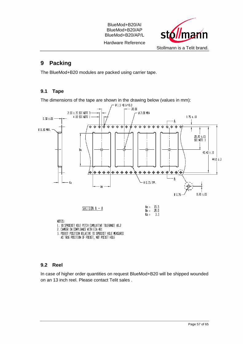
9.1 Tape
The dimensions of the tape are shown in the drawing below (values in mm):
9.2 Reel
In case of higher order quantities on request BlueMod+B20 will be shipped wounded
on an 13 inch reel. Please contact Telit sales .

BlueMod+B20/AI BlueMod+B20/AP
BlueMod+B20/AP/L
Hardware Reference Stollmann is a Telit brand.
Page 58 of 65
10 Label Information
10.1 Module Label
All module variants with internal antenna, denoted by string “AI” in the product
name, are marked with the following label:
Stollmann BlueMod+B20
FCCID: RFR-B2029IC: 4957A-B2029
aa
R 202-LSB042T D 13-0021 202
20
18
10
3
8
1,3
1) 2)
3)
4)
5)
6)
7) 8)
9)
Field Description Example / Remark
1) Manufacturer/Customer Stollmann
2) Product Name
3) FCC-ID FCCID: RFR-B2029
Product ID9) e.g. 04
BlueMod+B20
CE Marking8) acc. to 1999 / 5 / EC
4) IC-ID IC: 4957A-B2029
5) TTE Marking "Terminal"-Symbol + D 13-0021 202
6) Radio Marking "Radio"-Symbol + 202LSB042
7) Approval Label (Japan) MIC Marking
All module variants using an external antenna, denoted by string “AP” in the product
name are not marked with a label.:
The Label consists of white, self adhesive polyamide foil.

BlueMod+B20/AI BlueMod+B20/AP
BlueMod+B20/AP/L
Hardware Reference Stollmann is a Telit brand.
Page 59 of 65
10.2 Package Label
The package box is marked with the following label:
Stollmann E+V GmbHname
p/n
firmware
fw p/n
trace
quantity
designed and manufactured in Germany
BlueMod+B20/AP/XXXXX
aaaaa-aa
b/c
ddddd-dd
mwwyy
q
105
52
Stollmann E+V GmbHname
p/n
firmware
fw p/n
trace
quantity
designed and manufactured in Germany
BlueMod+B20/AI/XXXXX
aaaaa-aa
b/c
ddddd-dd
mwwyy
q
R 1,5
1)
2)
3)
4)
5)
6)
7)
8)
9)
10)
13)14)
15)
105
52
11)12)
Field Description
name Name of product
p/n Product number
firmware Firmware version
fw p/n Product number of firmware
trace Manufacturer Date (CalendarWeekYear) WWYY
quantity Number of contained modules
If the label on the package box is different to the label described above or if the
name, p/n or firmware are different to the information in your order, please contact
Telit for detailed information.

BlueMod+B20/AI BlueMod+B20/AP
BlueMod+B20/AP/L
Hardware Reference Stollmann is a Telit brand.
Page 60 of 65
11 Ordering Information
BlueMod+B20 is available in the following variants:
Name Antenna
Article No.
MOQ / units
Comments
BlueMod+B20/AI/I/SPP Internal 54357 50 Serial Port Profile Firmware
BlueMod+B20/AP/I/SPP External 52741 5000 Serial Port Profile Firmware
BlueMod+B20/AP/L/I/HCI-USB External 53062 500 HCI firmware, USB
BlueMod+B20/AI/I/BT2.1/MP Internal 53132 50 Bluetooth 2.1 compliant, Multi profile support (SPP/HID/OPP)
BlueMod+B20/AI/I/BT2.1/iAP Internal 53222 500 Firmware with Apple iAP support
BlueMod+B20/AP/L/I/BT2.1/MP External 53253 500 Bluetooth 2.1 compliant, Multi profile support (SPP/HID/OPP)
Other variants on request, please contact Telit sales department.

BlueMod+B20/AI BlueMod+B20/AP
BlueMod+B20/AP/L
Hardware Reference Stollmann is a Telit brand.
Page 61 of 65
12 History
Version Release Date By Change description
0.50 17.05.2006 GJ Correction: RESET# is active LOW
active LOW signal names end with # sign
0.60 23.05.2006 GJ Correction: AIO pinning
0.70 30.08.2006 BG/JW first combined version BlueMod+B20/Bluemod+B29
0.90 06.03.2007 FH/AA B29 removed,
1.00 12.03.2007 JW Enhanced 7.4 Bluetooth Qualification
First non preliminary version
1.01 28.03.2007 JJ Ergänzungen Cetecom, Foto updated
1.02 03.04.2007 AA/JW Figure 4.1 and 6.4 corrected
Added 7.1 Declaration of conformity and Startup time
1.03 03.04.2007 AA Chapter 3.1: DC-Voltages, Chapter 3.2 : Power ON Reset
1.04 02.05.2007 JJ Chapter 4.2.2 Application Specific Pin Description
Usage Tables completed
1.06 27.06.2007 AA First combined version BlueMod+B20/AI (internal antenna) and BlueMod+B20/AP (external antenna)
Chapter 4 and 6: Drawings for BlueMod+B20/AI actualised, for BlueNod+B20/AP new
r02
15.08.2007 AA/BG FH BG
FH/AA JW
New template Dimension corrected in chapter 1.1 Chapter 4: Figures Chapter 6.1: Figures Chapter 6.2: Figures Typos Grammar Minimum order quantities 3.8.2 removed and integrated in 3.8.3 and 3.8.4 (now 3.8.2 and 3.8.3) 3.9.1 moved to 3.9 Chapter « Safety Guidelines » removed Added last page Corrected Internal crystal oscillator (26 MHz) Formatting corrected in chapter 4 Pin Description
Note: It is highly recommended to make the SPI accessible in your design to ensure a future firmware upgrade for your mod-ule!
Pin Descriptionintroduced /C and /I versions added HCI variants corrected all tables in chapter 4 Pin Description
r03 13.12.2007 JW added MOQ for BlueMod+B20/AI/I/SPP removed commercial variant, no longer available article number for BlueMod+B20/AI/I/HCI corrected
AA 4.2 Pin Description Pinning for AP Version added 5.4 Digital I/O including RESET# Input Current 5.8 RF performance Output Power, BER and C/I corrected; 6.6 Antenna Issues Antenna Issues new 6.7 Safety Guidelines new
BlueMod+B20/AI BlueMod+B20/AP
BlueMod+B20/AP/L
Hardware Reference Stollmann is a Telit brand.
Page 62 of 65
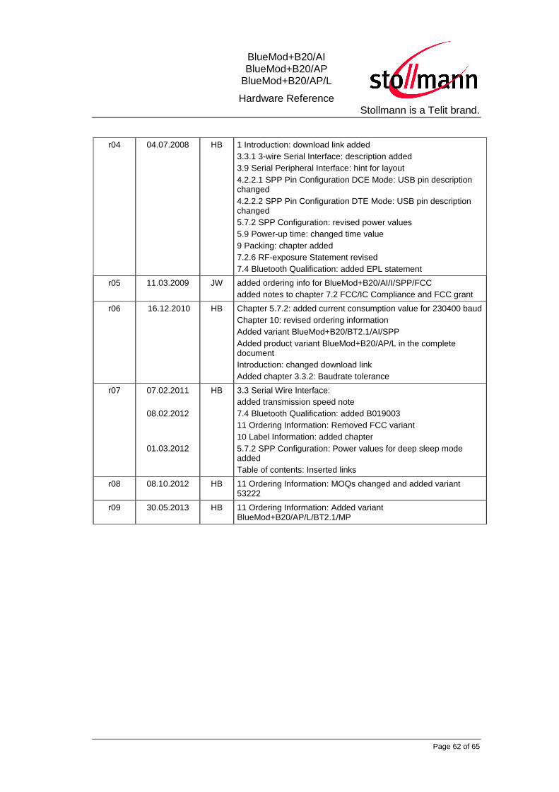
r04 04.07.2008 HB 1 Introduction: download link added
3.3.1 3-wire Serial Interface: description added
3.9 Serial Peripheral Interface: hint for layout
4.2.2.1 SPP Pin Configuration DCE Mode: USB pin description changed
4.2.2.2 SPP Pin Configuration DTE Mode: USB pin description changed
5.7.2 SPP Configuration: revised power values
5.9 Power-up time: changed time value
9 Packing: chapter added
7.2.6 RF-exposure Statement revised
7.4 Bluetooth Qualification: added EPL statement
r05 11.03.2009 JW added ordering info for BlueMod+B20/AI/I/SPP/FCC
added notes to chapter 7.2 FCC/IC Compliance and FCC grant
r06 16.12.2010 HB Chapter 5.7.2: added current consumption value for 230400 baud
Chapter 10: revised ordering information
Added variant BlueMod+B20/BT2.1/AI/SPP
Added product variant BlueMod+B20/AP/L in the complete document
Introduction: changed download link
Added chapter 3.3.2: Baudrate tolerance
r07 07.02.2011
08.02.2012
01.03.2012
HB
3.3 Serial Wire Interface:
added transmission speed note
7.4 Bluetooth Qualification: added B019003
11 Ordering Information: Removed FCC variant
10 Label Information: added chapter
5.7.2 SPP Configuration: Power values for deep sleep mode added
Table of contents: Inserted links
r08 08.10.2012 HB 11 Ordering Information: MOQs changed and added variant 53222
r09 30.05.2013 HB 11 Ordering Information: Added variant BlueMod+B20/AP/L/BT2.1/MP
BlueMod+B20/AI BlueMod+B20/AP
BlueMod+B20/AP/L
Hardware Reference Stollmann is a Telit brand.
Page 63 of 65
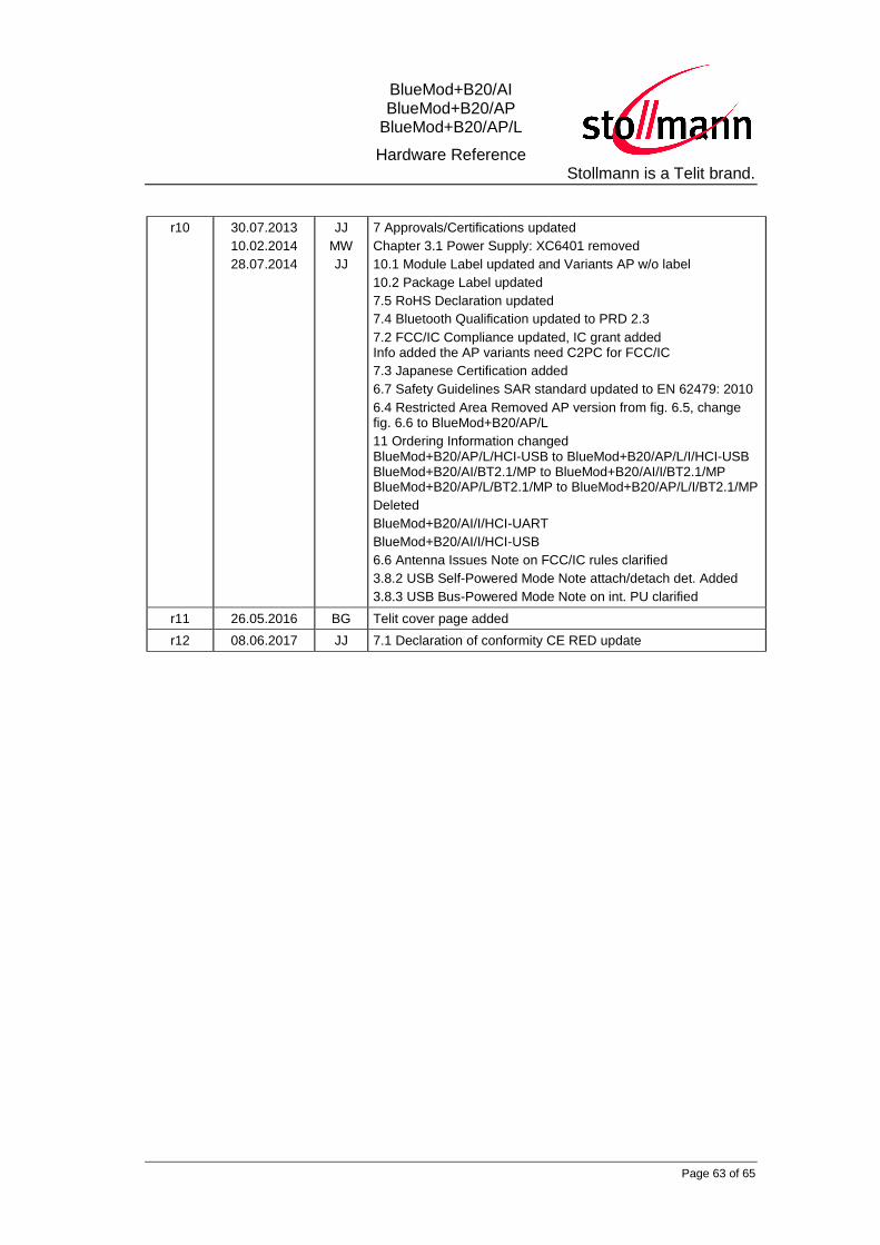
r10 30.07.2013
10.02.2014
28.07.2014
JJ
MW
JJ
7 Approvals/Certifications updated
Chapter 3.1 Power Supply: XC6401 removed
10.1 Module Label updated and Variants AP w/o label
10.2 Package Label updated
7.5 RoHS Declaration updated
7.4 Bluetooth Qualification updated to PRD 2.3
7.2 FCC/IC Compliance updated, IC grant added Info added the AP variants need C2PC for FCC/IC
7.3 Japanese Certification added
6.7 Safety Guidelines SAR standard updated to EN 62479: 2010
6.4 Restricted Area Removed AP version from fig. 6.5, change fig. 6.6 to BlueMod+B20/AP/L
11 Ordering Information changed BlueMod+B20/AP/L/HCI-USB to BlueMod+B20/AP/L/I/HCI-USB BlueMod+B20/AI/BT2.1/MP to BlueMod+B20/AI/I/BT2.1/MP BlueMod+B20/AP/L/BT2.1/MP to BlueMod+B20/AP/L/I/BT2.1/MP
Deleted
BlueMod+B20/AI/I/HCI-UART
BlueMod+B20/AI/I/HCI-USB
6.6 Antenna Issues Note on FCC/IC rules clarified
3.8.2 USB Self-Powered Mode Note attach/detach det. Added
3.8.3 USB Bus-Powered Mode Note on int. PU clarified
r11 26.05.2016 BG Telit cover page added
r12 08.06.2017 JJ 7.1 Declaration of conformity CE RED update

BlueMod+B20/AI BlueMod+B20/AP
BlueMod+B20/AP/L
Hardware Reference Stollmann is a Telit brand.
Page 64 of 65
Telit Wireless Solutions GmbH
Friesenweg 4
22763 Hamburg
Germany
Phone: +49 (0)40 890 88-0
Fax: +49 (0)40 890 88-444
E-mail: [email protected]
www.telit.com