Embed Size (px)
Citation preview

Jim Johnson
HVACR Troubleshooting Fundamentals
Refrigeration & Air Flow Systems

HVACR Troubleshooting Fundamentals
Refrigeration & Air Flow Systems
Jim Johnson

Library of Congress Cataloging-in-publication Data Johnson, Jim HVACR Troubleshooting Fundamentals: Refrigeration & Air Flow Systems ISBN-13: 978-1-937659-12-7 ISBN-10: 1-937659-12-7 © 2018 The MIE Instutute PO Box 2259 Green Valley, AZ 85622-2259 ALL RIGHTS RESERVED. No part of this work covered by the copyright herein may be reproduced, transmitted, stored or used in any form or by any means graphic, electronic, mechanical, including but not limited to photocopying, recording scanning digitizing, taping, Web distribution, information networks, or information storage and retrieval systems, except as permitted under Section 107 and 108 of the 1976 Copyright Act, without the prior written permission of the publisher.
Notice To The Reader The author and publisher do not warrant or guarantee any of the products described herein. The author and publisher do not assume, and expressly disclaims, any obligation to obtain and include any information other than that provided by the manufacturer. The reader is expressly warned to consider and adopt all safety precautions that might be indicated by the activities indicated herein and to avoid all potential hazards. By following the instructions described herein, the reader willingly assumes all risks in connection with such instructions. The author and publisher make no representations or warranties of any kind, including
but not limited to, the warranties of fitness for particular purpose or merchantability, nor
are any such representations implied with respect to the material set forth herein, and
the author and publisher take no responsibility with respect to such material.

HVACR Troubleshooting Fundamentals Refrigeration & Air Flow Systems
CONTENTS
Preface…………………………….i List of Illustrations………………..v
SECTION ONE: REFRIGERATION FUNDAMENTALS
Unit 1 Heat Energy……………………….2
Radiation… Conduction… Convection… The British Thermal Unit… Understanding Sensible & Latent Heat
Unit 2 Refrigeration System Components and Accessories ……………………….18
Compressors… Condensers… Evaporators… Metering Devices… Filter Driers… Heat Exchangers….Suction Line Accumulators… Liquid Line Receivers
Unit 3 The Refrigeration Cycle……………49 Simplified Refrigeration system… Refrigerant Temperature & Pressure… High Pressure and Low Pressure In Refrigeration Systems… Purpose of Evacuation In Refrigeration Systems

Unit 4 Superheat & Subcooling……………71 The 70-Pound Rule… The 30- Degree Rule… Refrigerants and Oils, Comparing R-22 & R-410A… Refrigerant Flammability and Toxicity... Simplifying Superheat In Refrigeration Systems… Questions and Answers About Superheat… Employing Superheat In A Diagnosis… Manufacturer’s Charging Charts… Evaporator Superheat…. Total Superheat In A Refrigeration System… Discharge Superheat… Subcooling In Refrigeration systems… Fundamental Diagnostics Related To Refrigeration System Pressures
Unit 5 Evacuation and Dehydration…………104 Vacuum and Pressure… Microns & Micron Gauges… Vacuum Pump Maintenance & Operation
Unit 6 Accessing Refrigeration Systems For Refrigerant Recovery & Evacuation….123
Accessing Small Refrigeration Systems… Schrader Valves… Schrader Valve Core Removal Tools… Quick Connect Fittings… Compressor Mounted Access Valves… Liquid First Refrigerant Recovery Procedures… Manifold Gauge Set Fundamentals… Refrigerant Recovery Drum Safety… Push/Pull Refrigerant Recovery… Non-Condensable Materials and Contaminants… Cooling A Recovery Tank… System Evacuation & Removing Moisture

SECTION TWO: AIR FLOW & HVACR EQUIPMENT EVALUATION
Unit 7 Properties of Air & Fundamental Air Flow Measurements……………………….158
Air Density & Specific Heat…. The 1.08 and 4.5 Multiplier Factors…. Air Flow Measurement: CFM & FPM…. Using FPM To Calculate CFM…. Air Flow Calculations & Load Estimating
Unit 8 Psychrometric Principles…………….176 Fundamentals of Psychrometrics, DB WB & RH…. Structure of the Psychrometric Chart…. Calculating RH & Wet Bulb Depression…. Dew Point…. Common Properties of Air Formulas….
Unit 9 Supply & Return Air System Fundamentals.…………………………203
Air Flow & TD Through A Free Blowing DX Coil…. Air Flow Through A Forced Air Condenser…. Air Flow Fundamentals of Ducted Systems…. Supply Duct Systems & TEL…. Return Duct Systems & TEL
Unit 10 HVACR System Air Flow System Evaluation………………………………228
Supply Air Flow Configurations…. Return Air Flow…. Manufacturer’s Blower Performance Data…. Static Pressure Testing…. Dry Bulb & Wet Bulb Temperature Measurements…. Temperature Split…. Blower Door Testing…. Duct Leakage Testing…. Appendix A Troubleshooting Problems…………260


i
Preface
For technicians, it’s always about troubleshooting. Most of the time, it’s a very direct situation. A customer calls and says, “My air conditioner is running but the house is warm” or, “Our walk-in is running at 55 degrees” or, the information you get may be in simple, two-word sentences: “No heat”, “No ice”, “Not running”. In some cases, you may be called on to perform preventive maintenance, but that’s still troubleshooting. You’re evaluating the performance of the equipment, checking components to determine whether or not they may be potential problem, and comparing the actual results you’re getting from your tests to what you know to be the normal operating characteristics or manufacturer’s specifications of the equipment. Or, you may be tasked with accomplishing an equipment installation, which is also a form of troubleshooting. If the installation isn’t done right, then the system can’t perform as it is designed to, and a problem will have to be solved before that equipment will be able to transfer heat properly, move air properly, or make the correct size of ice cubes. The philosophy behind this book is to consider troubleshooting from a simple and direct approach, beginning with understanding a to-the-point definition of the process: Troubleshooting is the systematic elimination of possibilities.
And, along with this simple definition, there is a question you need to consider when you are learning to troubleshoot: How will you ever know what’s wrong with something if you don’t know what right is in the
first place?
In some cases, knowing what right is comes down to simple common sense; a general understanding of the components of a refrigeration system, along with the process of indoor air flow through a duct system along with the outdoor air flow through a coil, and how these systems fundamentally work in all applications. And sometimes, the only source for right is the manufacturer’s specific fault code and explanations, along with step-by-step troubleshooting procedures. Whether the information must simply be understood from an overall perspective, or gleaned from a manufacturer’s instructions, tracking down the source of a problem in a refrigeration, or air flow system is a skill that must be developed on an individual basis.

ii
Different people think differently, and what may seem to be the wrong place to begin troubleshooting a given problem for one person, may be the right place for another. With basic concepts of HVACR equipment operation understood, in order to benefit most from the contents of this text, an effort on the part of the reader is necessary. While there may be some things that can be learned in a passive mode, troubleshooting is
not one of them.
In order to become an effective refrigeration and air flow systems troubleshooter, a firm understanding of the basics of refrigeration and air flow concepts must be established before equipment performance problems can be diagnosed, or air flow systems can be evaluated. With the information in this book fully understood, you will have the foundational tool you need to put your knowledge into practice. And practice…actually doing the work….is what you need to do in order to achieve a level of mastery in your craft. Gaining knowledge is a fundamental step to being a technician, but only experience can
make you an expert in your field.
This is not to say that every time you connect a set of gauges to a system you have to stop and review the fundamentals of heat transfer and thermodynamics before you check refrigerant pressures. Or that you need to go through every fundamental concept related to the science of psychrometrics before using an anemometer or flow hood to measure air flow in a comfort cooling or heating system. However, knowing the fundamental concepts of what makes things work, and eliminating the mystery behind it all, clears the way for a full understanding of how refrigeration and indoor and outdoor air flow systems systems are used to perform work in HVACR equipment. And once you know… and you know you know… you can become a true troubleshooter.
________________________________________________ ACKNOWLEDGEMENTS
When I wrote my first textbook, there were many people to thank, and one segment of the dedication read “…to my wife Peggy Lee, who has been with me through all the ups and downs and twists and turns of my personal and professional life for 25 years…” and, here is the dedication for this book….

iii
Dedication: To my wife Peggy Lee, who has been with me through all of the ups and downs and twists and turns of my personal and professional life for 50 years. Thanks To: I would like to thank Renee Tomlinson for her help in developing this updated version of the original text, ESCO Group, Eugene Silberstein and Carter Stanfield for their permission to use images from their work, Fieldpiece Instruments, Appion Inc., Retrotec, Copeland Corporation, Tecumseh Products Company, and Fedders North America for images from their manuals, Parker-Sporlan for temperature/pressure chart and TEV images, RSES Journal & Indoor Comfort News & ACHR News readers who have helped in contributing to the development of troubleshooting problems, and to the students in my trade school classes and technicians who have attended my workshops and were not afraid to ask questions.

iv

v
HVACR Troubleshooting Fundamentals Refrigeration & Air Flow Systems
LIST OF ILLUSTRATIONS
UNIT 1
Heat Energy
Figure 1-1 Heat always moves from a warmer surface to a cooler surface, and in the event that the volume of the two substances are equal, an equalization of temperature occurs. Pouring a one-quart container at 70°F and a one-quart container at 90°F into a two-quart container results in two quarts of liquid at 80°F. Figure 1-2 Infrared heating units are an illustration of heat movement through radiation. An overhead unit, such as the one shown, is used in drafty work areas to warm workers without warming the air. Figure 1-3 Conduction can be illustrated by placing one end of a length of copper tubing into an open flame. In time, the heat will travel the full length of the tubing. Figure 1-4 Air flows naturally through a baseboard heating system. The warm air rises and the cooler air falls.
Figure 1-5 An illustration of the British Thermal Unit.
Figure 1-6 Latent heat removal brings about a change in state, but not a change in temperature. Figure 1-7 A scale showing the different heat index levels of different substances. Figure 1-8 In order to accomplish the latent heat of vaporization of I lb. of water, 970.4 BTUs of heat must be added. Shown here as 970 BTUs per lb. degrees Fahrenheit. Figure 1-9 The common temperature scales used in the HVACR industry.

vi
UNIT 2
Refrigeration System Components and Accessories
Figure 2-1 In a reciprocating compressor, the temperature and the pressure of the refrigerant are increased when the area occupied by the vapor is decreased by the action of the piston. Note: PSIG stands for Pounds Per Square Inch Gauge.
Figure 2-2 On larger systems such as those found in apartment complexes and office buildings, a coupler-driven compressor is often used. (Courtesy The Trane Company, LaCrosse, WI)
Figure 2-3 A welded dome compressor is also known as a hermetic compressor and is not serviceable. (Courtesy Tecumseh Products Company)
Figure 2-4 A semi-hermetic compressor can be disassembled for some field service repairs. Specialty shops remanufacture semi-hermetic compressors. (Courtesy Copeland Corporation)
Figure 2-6 The eccentric is the component that creates the elliptical pattern in a rotary compressor. (Courtesy Fedders North America) Figure 2-7 In a rotary compressor, suction and discharge take place simultaneously. (Courtesy Fedders North America) Figure 2-8 A screw compressor uses two closely machined components to create the pressure rise in a refrigeration system. Figure 2-9 One example of an impeller in a centrifugal compressor. Some compressors of this type employ a multi-stage design, which means the refrigerant enters a first stage impeller and is discharged into the suction of a second stage impeller. Refrigerant then exits the second stage impeller and is sent out of the compressor via the discharge line. Figure 2-10 The sequence of operation of a scroll compressor. (Courtesy Copeland Corporation) Figure 2-11 A finned condenser tubing assembly found in window air conditioners. Figure 2-12 A tube-in-a-tube condenser allows the use of water as a heat transfer agent in a refrigeration system. Figure 2-13 In a shell-and-coil condenser assembly, the finned condenser is housed in a welded dome. Water is piped through the dome to cool the hot vapor.

vii
Figure 2-14 A plate type evaporator that is formed to create a freezer section of a small refrigeration system. Figure 2-15 A plate type evaporator in a commercial ice making system. Figure 2-16 One application of a finned evaporator. This type of evaporator is also found in frost free refrigerators and freezers, comfort cooling systems, heat pumps, and walk-in coolers and freezers. Figure 2-17 An evaporator coil in a refrigeration system that uses water as a heat transfer agent. The refrigeration system absorbs heat directly from the water in contact with the evaporator coil. Figure 2-18 A capillary tube is usually coiled up due to its length. Figure 2-19 A thermostatic expansion valve (also known as a TEV or TXV) is a metering device that adjusts the refrigerant flow into an evaporator to meet the system load. (Courtesy Sporlan) Figure 2-20 A thermostatic expansion valve is commonly used in commercial refrigeration systems such as those found in grocery store or restaurant equipment. (Courtesy Copeland Corporation) Figure 2-21 Refrigerant flow from an EEV is controlled by a microprocessor system made up of a sensor and controller circuit board that varies the amount of refrigerant allowed into the evaporator according to the increase and decrease of the heat load in the conditioned space. Figure 2-22 The heart of a small refrigeration system, the compressor, connected to the discharge line. Figure 2-23 The compressor of a small refrigeration system connected to the condenser. Figure 2-24 Here, we have added the filter drier at the exit point of the condenser. A filter drier in this position in the refrigeration system is commonly referred to as a liquid line drier. Figure 2-25 This illustration shows the metering device of a small refrigeration system, the capillary tube, as it is connected to the outlet of the liquid line filter drier.
Figure 2-26 The capillary tube metering device connects from the outlet of the filter drier to the inlet of the evaporator coil.
Figure 2-27 This illustration shows a complete small refrigeration system with the filter drier and heat exchanger as accessories. When the capillary tube, which is warm, is bonded to the suction line, which is cool, the warm refrigerant in the capillary tube gives up its heat to the cooler suction line. Figure 2-28 A rotary compressor at 50% suction and 50% discharge, 100% vapor.

viii
Figure 2-29 A rotary compressor being affected by hydraulic skip. The liquid droplets are occupying space, thereby limiting the efficiency of the compressor to move vapor from suction to discharge. Figure 2-30 A suction line accumulator positioned near an evaporator coil. Figure 2-31 An accumulator in the refrigeration system of a room air conditioner is positioned in the suction line near the compressor. Figure 2-32 A filter drier contains a material known as a desiccant that absorbs moisture and it also contains a screen for capturing particulates. It is installed after the condenser (see Figure 2-16) and has a specific inlet and outlet connection. An arrow on the body of the valve shows the direction of refrigerant flow through it. Figure 2- 33 A simplified illustration of a suction line accumulator. Refrigerant leaves a system evaporator and travels through the suction line toward the compressor, entering tube connection #1 of the accumulator. If there is any liquid, it falls to the bottom of the accumulator, allowing only vapor to enter the internal connection to tube connection #2, ensuring that no liquid will travel to the compressor. Some accumulators will also have a tubing connection that will allow for oil return to the compressor. Figure 2-34 Some liquid line receivers are equipped with a dip tube as shown here. Receivers may also have an inlet at the top and an outlet at the bottom. A receiver can be a vertical type, or it may be a horizontal design, and can also have a pressure safety valve. Regardless of the design, the objective is the same: To store excess refrigerant in systems that employ modulating type metering devices and ensure that liquid enters the metering device.

ix
UNIT 3
The Refrigeration Cycle
Figure 3-1 A Simplified refrigeration system that uses a capillary tube as the metering device. Figure 3-2 Tracking the pressure and temperature of the refrigerant as it flows through the system. The pressures and temperatures shown here relate directly to the refrigerant R-22. Figure 3-3 A partial temperature/pressure chart that shows the boiling points of four refrigerants. Positive pressures are shown in bold and negative pressures are shown in italics. This chart represents a time frame in the HVACR industry when chlorine based refrigerants (R-12, R-22 and R-502) were still in use, and R-134A was the first HFC refrigerant introduced. Figure 3-4 A pressure gauge that shows both positive pressures above 0 PSIG and negative pressures in a vacuum. Figure 3-5 A partial temperature/pressure chart that shows high side operating pressures of a refrigeration system. Figure 3-6 Refrigerants maintain a constant vapor pressure regardless of the amount of liquid in the container. The drum on the left is filled to capacity at 80% of the cylinder volume. The drum on the right contains only about 10% of the drum capacity. If these drums contained the same refrigerant, checking both of them drums with a gauge would show the same vapor pressure. Figure 3-7 Dividing the system into its low pressure and high pressure components. The compressor and metering device create the pressure differential necessary to operate the refrigeration system. Figure 3-8 When a heat pump refrigeration system is operating in the cooling cycle, the discharge from the compressor is to the outdoor coil. Figure 3-9 When a heat pump refrigeration system is operating in the heating cycle, the discharge from the compressor is to the indoor coil. In this mode, the check valve near the outdoor coil doesn’t allow refrigerant flow, forcing the flow through the metering device and into the outdoor coil.
Figure 3-10 The segment of the reversing valve known as the pilot valve assembly is connected to the valve body on both sides, along with another connection that is routed to a refrigerant line at the valve body. The lines connected to the pilot valve assembly are small, sometimes referred to as capillary lines.

x
Figure 3-11 When the heat pump is operating in the heating mode, refrigerant flow is directed to the indoor coil due to the change in operation of the electrical system, which results in a change in the pressure in the pilot valve assembly. The change in pilot valve assembly causes the slide assembly to shift its position. Figure 3-12 When a reversing valve is operating properly, the temperature difference between the entry and exit point of refrigerant from the body of the valve will be minimal, usually no more than 2 or 3 degrees. Checking the temperature at Entry Point A and Entry Point B with an accurate digital device and finding a temperature difference higher than normal indicates that the slide assembly is not seating, allowing heat transfer from one segment of the system to the other.

xi
UNIT 4
Superheat & Subcooling In Refrigeration Systems
Figure 4-1 A temperature/pressure chart that shows a side-by-side comparison of R-22 and R-410A. From a general perspective, R-410A operates at pressures that are approximately 50% higher than R-22. Figure 4-2 Standard compound gauge sets showing typical operating pressures of an R-22 system and equipment using R-410A as the refrigerant. Figure 4-3 This matrix shows the two factors to consider relative to the safety of a refrigerant. The two scales are flammability and toxicity. A refrigerant that has the lowest rating and would be considered safe, would be rated as an A1 refrigerant. Figure 4-4 A simplified illustration of an evaporator coil showing the point at which superheat will begin to be picked up by the vapor refrigerant. Figure 4-5 Refrigerant enters the evaporator as a low pressure liquid, is a mixture of liquid and vapor during the process of absorbing heat, then becomes a vapor only in the last section of the coil, allowing for the sensible heat gain of superheat. Figure 4-6 A generic chart that can be used in the process of evaluating the superheat in a refrigeration system. Figure 4-7 A temperature/pressure chart is used to convert a pressure reading to a temperature in the process of calculating superheat. Figure 4-8 One example of a manufacturer’s superheat charging chart. Figure 4-9 An example of determining Evaporator Superheat. Figure 4-10 A list of factors other than a system overcharge that could cause a higher-than-normal suction pressure and lower-than-normal superheat. (Sporlan illustration) Figure 4-11 A list of factors other than a system undercharge that could cause a lower-than-normal suction pressure and higher-than-normal superheat. (Sporlan illustration) Figure 4-12 A list of factors other than a system overcharge that could cause a higher-than-normal suction pressure and lower-than-normal superheat. (Sporlan illustration)

xii
Figure 4-13 An illustration showing an evaporator superheat of 10°F. Figure 4-14 This illustration shows the point in the evaporator coil where superheat will begin being picked up. When accessing the system and checking temperature near the compressor, the superheat gained in the entire suction line is also part of the calculation. Figure 4-15 Accomplishing temperature and pressure measurements to calculate discharge superheat. Figure 4-16 A segment of a Sporlan temperature/pressure chart. Figure 4-17 Desuperheating, condensing and subcooling taking place in a condenser coil. Figure 4-18 A temperature/pressure chart showing various refrigerants, including R-22. Figure 4-19 A subcooling chart used for checking refrigerant charge. Figure 4-20 In the last R-22 column to the right of this chart, locate the reading 226.4 PSIG. Figure 4-21 The subcooling chart showing a 95-degree ambient and 67-degree wet bulb. Figure 4-22 A segment of a slide rule device used to calculate subcooling and superheat. Figure 4-23 A segment of a Pressure/Temperature chart. Figure 4-24 In a refrigeration system, the evaporator and suction line are low pressure, the condenser, receiver, liquid line and discharge line are high pressure.

xiii
UNIT 5
Evacuation & Dehydration
Figure 5-1 When graphs and charts are used relative to refrigeration systems, the scale of one square inch is the standard unit of measurement applied.
Figure 5-2 An illustration of atmospheric pressure pushing down onto one square inch of surface area. At sea level this pressure is 14.7 PSI. Figure 5-3 A chart showing the effects of elevation on atmospheric pressure. The higher the elevation, the lower the pressure. The lower the elevation, the higher the pressure. Figure 5-4 Atmospheric pressure pushing down onto one square inch of surface area at sea level is 14.7 PSI. Mercury will rise to 30 inches. Figure 5-5 A micron gauge is a device that is connected to a refrigeration system while it is being evacuated. (Image courtesy of Fieldpiece Instruments) Figure 5-6 A vacuum pump connected to a refrigeration system. In this example the compound gauge set is connected to the low side access valve of the refrigeration system at the right of the compressor, and the high side access is on the left. A Tee connector at the vacuum pump allows the micron gauge to measure the level of vacuum being achieved. Figure 5-7 A digital gauge set that allows for refrigerant pressure monitoring as well as superheat and subcooling measurements of an operating refrigeration system. A built-in micron gauge allows for accurate vacuum measurement when evacuating a system. (Image courtesy of Fieldpiece Instruments) Figure 5-8 One type of two-stage vacuum pump used in refrigeration system servicing. Equipment of this design employs a sight glass to monitor the level of oil in the pump assembly, a drain plug at the bottom of the pump casing, and an accessible fill opening at the top. Figure 5-9 Manufacturers commonly make repair parts available for vacuum pumps due to the normal wear and tear that can occur with their use. Figure 5-10 A canister contains the amount of oil needed to operate the vacuum pump.
Figure 5-11 After opening the access door on the vacuum pump, the canister can be removed. (Courtesy of Appion Inc) Figure 5-12 Installation of a fresh canister of oil is accomplished at the beginning of the service procedure and can be done if necessary during the evacuation process. (Courtesy of Appion Inc)

xiv
UNIT 6
Accessing Refrigeration Systems For
Refrigerant Recovery & Evacuation
Figure 6-1 A saddle valve that is installed on small refrigeration systems. Upon installation, it pierces the refrigerant line. Manufacturers recommend that this type of valve should be installed on copper or aluminum tubing. Figure 6-2 After a hole is pierced in the tubing the cap is removed and the piston is discarded. Figure 6-3 A small refrigeration system compressor shown with the suction line on the left and the discharge line on the right. The valve installed on the suction line allows a service hose connection to monitor the low side operating pressure. Figure 6-4 A process stub, which can be crimped and soldered shut on the end, also allows for the installation of an access valve that allows for low side pressure readings directly at the compressor. Figure 6-5 A soldered saddle valve is another type of access that can be installed on small refrigeration systems. Figure 6-6 An illustration of a small refrigeration system without access valves. Figure 6-7 A replacement filter drier installed on a small refrigeration system after a repair has three connections, one for a service hose connection. Figure 6-8 When the spring loaded section of a Schrader valve is depressed by a depressor stem in a service hose fitting, the refrigeration system is accessed. Figure 6-9 The core of a Schrader valve may be replaced if it is not sealing properly. Figure 6-10 A tool that accomplishes the removal and replacement of a Schrader valve core. Figure 6-11 This Schrader valve core removal tool is used to replace a core in a system containing refrigerant, It also allows for the removal of the core to minimize restriction when recovering refrigerant and evacuating a system, and re-installing the core upon completion of the service procedure.

xv
Figure 6-12 With the tool connected to the access valve, push the stem down until it grabs the core, then turn counter-clockwise to remove the core. With the stem pulled back until it stops, close the valve assembly and remove the stem and the core. Figure 6-13 With the stem and core removed, connect a service hose to the tool, and also connect a micron gauge to the side port. Open the valve to recover or evacuate, and reverse the procedure to replace the core. Figure 6-14 Quick connect fittings allow the technician to first install the female knurled connector to the Schrader valve hose connection, than after installing a service hose from a gauge set to the male connector of the fitting, the fitting depressor is pressed into place and clipped to knurled connector. Figure 6-15 A compressor mounted access valve is commonly bolted to the compressor body. Figure 6-16 A refrigeration service valve wrench has square openings to accommodate the compressor mounted service valve adjusting stem. Figure 6-17 In a back-seated position the compressor mounted access valve stem is turned counter-clockwise. In this position, the system operates, but there is no access to the service port. Figure 6-18 In the front-seated position, the compressor mounted access valve stem is turned clockwise. In this position, the compressor cannot be operated. Attempts to operate the compressor with the valves in the front-seated position can cause damage. Figure 6-19 With the valve stems adjusted to a “cracked” position, the refrigeration system operation can be monitored and via a gauge set connected to the high and low side service ports. Figure 6-20 Upon initiating a pump-down procedure, the access valve at the outlet of the receiver (referred to as a King Valve) is closed. With the compressor operating, and the compressor mounted service valves in a mid-seated position to allow pressure monitoring, refrigerant is pumped into the receiver to be stored. Figure 6-21 As the pump-down procedure is being completed, the suction side of the compressor is isolated by front-seating the access valve. Figure 6-22 Connecting to both the high and low pressure side access valves of a system will facilitate the refrigerant recovery process is as timely a manner as possible. Removal of the Schrader valve cores will also minimize restriction of refrigerant flow.
Figure 6-23 When recovering liquid first, the high side gauge is connected to the access valve located for liquid refrigerant and the low side gauge is connected to a vapor located valve. The outlet of the recovery equipment is connected to the liquid port of a DOT (Department of Transportation) approved recovery drum.

xvi
Figure 6-24 Technicians need to understand the proper positioning of the valve seats in a gauge set. Figure 6-25 A refrigerant recovery drum has two inlet ports. A liquid port (red valve knob) with a dip tube that directs refrigerant to the bottom of the drum and a vapor port (blue valve knob) that allows refrigerant flow directly into the drum. Figure 6-26 Overfilling and transporting a refrigerant recovery drum can result in an explosion. Severe temperatures may occur inside a vehicle that is located in a high ambient temperature environment. Figure 6-27 The Push/Pull method of refrigerant recovery can be used when a large quantity of refrigerant (15 lbs. or more in a system that has a receiver) needs to be recovered. Figure 6-28 When making connections for the Push/Pull method of recovery without gauges, hose extensions with shut off valves can be used to control the flow of refrigerant during the siphoning process. Figure 6-29 A refrigerant recovery machine can be used to cool a recovery cylinder that contains at least 5 lbs. of refrigerant. Figure 6-30 When connecting a 3-hose gauge set to a refrigeration system for evacuation, the center hose is attached to the vacuum pump, the high side gauge hose is connected to the discharge segment of the system, and the low side gauge hose is connected to the suction side of the system. All the access valves are mid-seated. Figure 6-31 This Schrader valve stem, even though the core has been depressed by the installation of a service hose, is causing a restriction in flow. Figure 6-32 With the core of the Schrader valve removed, free flow through the access valve is allowed. Figure 6-33 Energizing a compressor crankcase heater and/or turning on the indoor and outdoor fans can, if the ambient temperature is sufficient, raise the temperature of the refrigeration system components. Figure 6-34 A chart showing the effect that lowering pressure has on the boiling point of water. Note that water will boil at a temperature of 15 degrees F at a vacuum pressure of 29.84 in. hg. (Courtesy ESCO Group)
Figure 6-35 An electronic vacuum gauge is connected with a tee on the suction side of the vacuum pump. Figure 6-36 In this example the micron gauge is connected with a tee directly at the suction access valve of the refrigeration system. (Image courtesy of Carter Stanfield)

xvii
Figure 6-37 When evacuating a system with compressor mounted access valves, connecting the micron gauge to the discharge service valve is an option that will allow monitoring of the vacuum level through the suction access valve and the suction side of the vacuum pump. (Image courtesy of Carter Stanfield)

xviii
UNIT 7
Properties of Air &
Fundamental Air Flow Measurement
Figure 7-1 Indoor and outdoor air flow through a small refrigeration system, a window-mounted room air conditioner. Figure 7-2 With the air handler and indoor coil located in the basement, air flow is returned into the blower plenum, being drawn through the filter, then forced through into the contact side of the evaporator back into the conditioned space. Figure 7-3 When air is forced through a fin and tube condenser coil at the proper volume and velocity, the cooled liquid refrigerant will return through the refrigeration system metering device and enter the indoor coil at the proper temperature, enabling the designed level of heat absorption from the conditioned space. Figure 7-4 Liquid refrigerant enters the indoor coil tubing and in the process of change from liquid to a vapor, cools the air passing through and contacting the coil fins. As the air is cooled, moisture is removed. Figure 7-5 An air flow hood, when positioned over a supply register, measures volumetric air flow. It is also used to measure return air, and can be used to evaluate air flow in all areas of a building in order to accomplish necessary balance and adjustment procedures. Figure 7-6 A hand-held anemometer, while it is not a substitute for an air flow hood, can be used to measure air flow in FPM. A device such as this can also measure the temperature of the air being discharged from a supply register. Figure 7-7 Air flow in this duct is shown at a velocity of 500 FPM. The duct is 12” W and 24” H, shown as 1ft. by 2ft. to simplify the formula for calculating CFM. (Image courtesy of Eugene Silberstein) Figure 7-8 Air flow in this duct is shown at a velocity of 600 FPM. The duct is 24” W and 24” H. Our calculations will show that the volume of air flow in this duct is 2,400 CFM. (Image courtesy of Eugene Silberstein)
Figure 7-9 A 1,268 sq. ft. two bedroom, one bath home. Each of these rooms require a different amount of air flow in CFM in order for a comfort cooling system to keep the building comfortable.

xix
Figure 7-10 Applying a multiplying factor of .8 provides a general overview of the volume of air that should be delivered to each area in order for the comfort cooling system to operate as designed. Figure 7-11 Heat gain that occurs in a building from both outside and inside sources is considered when comfort cooling equipment is sized to handle the load.

xx
UNIT 8
Psychrometric Principles
Figure 8-1 A psychrometric chart allows for the plotting of temperature and moisture conditions. Figure 8-2 The segment of the psychrometric chart that shows the dry bulb temperature lines. These lines run directly from the bottom of the chart. Figure 8-3 The segment of the psychrometric chart that shows the wet bulb temperature lines. These lines run from the instep, toward the heel at an angle of approximately 30 degrees. Figure 8-4 The segment of the psychrometric chart that shows the relative humidity lines. These lines follow the pattern of the curved line (instep) of the chart and they are shown in a percentage. Figure 8-5 The segment of the psychrometric chart that shows the dew point temperature lines. These horizontal lines are also used as indicators on the Specific Humidity moisture scale. Figure 8-6 The segment of the psychrometric chart that shows the specific volume lines. Figure 8-7 The segment of the psychrometric chart that shows the enthalpy lines. Figure 8-8 The Sensible Heat Ratio scale is another component of the psychrometric chart. It is located at the top right, shown here on a partial chart, and identified as SHR. Figure 8-9 The Sensible Heat Ratio scale may also be identified as the Sensible Heat Factor on some psychrometric charts. Figure 8-10 Plotting a state point on a psychrometric chart. Figure 8-11 Plotting the result of the operation of the equipment that is not operating properly. Figure 8-12 Plotting the result of the operation of the equipment that is operating properly. Figure 8-13 A chart that shows wet bulb depression can be used to determine relative humidity in a sample of air by measuring dry bulb and wet bulb temperatures, and calculating the difference between the two temperatures.
Figure 8-14 When dry bulb and wet bulb temperatures are plotted to measure relative humidity, they also allow the psychrometric chart to show the dew point temperature of the air.

xxi
Figure 8-15 The symbol Delta T for temperature difference, shown in a formula for considering temperature rise, known as sensible heat formula. Figure 8-16 The symbol Delta H, indicating a change in heat content, which is also referred to as enthalpy, is used in a formula. Figure 8-17 When using a wet bulb temperature to enthalpy conversion chart shown here, the procedure involves measuring any wet bulb temperature and selecting it in the left column, then selecting the tenth of the degree reading from the columns in the main body of the chart.

xxii
UNIT 9
Supply & Return Air System Fundamentals
Figure 9-1 When refrigeration equipment is applied to commercial refrigeration applications such as walk-in coolers, it is common to find a multi-circuit evaporator. When the air flow system is designed for this type of unit, the method of refrigerant distribution into the coil is taken into account. Figure 9-2 A single circuit evaporator system has only one inlet for liquid refrigerant flow into the coil. Figure 9-3 An accurate digital device is used to measure inlet and outlet air temperatures of a coil before calculating TD through an evaporator, and refrigerant temperature is also considered. Figure 9-4 On this temperature/pressure chart we can calculate that an R-134a system that is operating at a low side pressure of 22 PSIG will have a refrigerant saturation temperature of 25 degrees F. Figure 9-5 A standard forced air condensing unit in which the refrigerant enters in a vapor state at the top of the tube system and exits as a subcooled liquid at the bottom. The propeller fan draws air in through the coil and exhausts heat upward. Figure 9-6 A segment of a T/P chart that shows operating pressures relative to temperatures. Figure 9-7 This chart shows a range of operating temperatures for the three categories of refrigeration systems (Low, Medium & High Temp), and a column showing a range of temperatures relative to temperature rise. Figure 9-8 A temperature/pressure chart that shows a range of condensing temperatures related to the operation of the high pressure side of a refrigeration system. Figure 9-9 Static pressure in an HVACR supply duct. This positive pressure is a result of the air flow in volume and velocity through the duct. Figure 9-10 An example of measuring static pressure in a residential split system air conditioner. The measurement in the return section of the air handler is a negative pressure and the measurement in the supply section is a positive pressure. (Image courtesy of ESCO Group)
Figure 9-11 The TEL of this duct assembly, without any branches or fittings that would affect the flow of air, is 100 ft.

xxiii
Figure 9-12 Even though this duct assembly occupies the same physical distance as the last example, the TEL is 180 ft. due to the addition of fittings. Figure 9-13 A 90-degree Ell duct fitting, depending on its size in width and height, and the radius of the turn of the fitting, will have an assigned equivalent length. Figure 9-14 In this illustration of an upflow air handling system, the fitting at the left has an effective length of 35 ft. and will result in a higher pressure drop than the fitting at the right with an effective length of 10 ft.. Figure 9-15 When air is re-directed in a 90-degree Ell fitting, the result is turbulence, often referred to as Eddy Currents, at the throat of the fitting. Figure 9-16 Eddy Currents, sometimes referred to as Eddies, are reduced when splitters, AKA turning vanes, added to an Ell fitting. Figure 9-17 Excessive Eddy Currents can also occur in a duct assembly when a reduction in duct size is accomplished in abrupt manner. Figure 9-18 When proper procedure is followed, taking angles and duct size into account, a large to small duct transition does not result in excessive eddies.
Figure 9-19 When considering TESP (Total External Static Pressure) in a duct system, the TEL of the return segment and the TEL of the supply segment result in a total TEL.

xxiv
UNIT 10
HVACR Air Flow System Evaluation
Figure 10-1 One type of supply duct system found in residential and light commercial applications. It can be referred to as a trunk and branch system or as an extended plenum system.
Figure 10-2 These supply branches are numbered according to their distance from the air handler for the purpose of accomplishing a dry bulb temperature test at the supply registers. Figure 10-3 A type of duct system in which all branches are positioned near the same location in the air supply plenum is known as a radial system.
Figure 10-4 A perimeter loop duct system is commonly found in residential applications in cold climates because they’re very efficient at providing heat at the floor level. Figure 10-5 A manufacturer’s blower table shows what the static pressure in an air handling system should be under given conditions. (Trane/American Standard Inc.) Figure 10-6 The return and supply air system in a horizontal air handler, showing the equipment blower, heat exchanger, and cooling coil. A digital manometer can be used to measure the static pressure entering the blower (Point A) and leaving the blower (Point B). Figure 10-7 A dual port digital manometer can be used to measure both return and supply static pressure simultaneously. A device such as this may also calculate TESP. (Image courtesy Fieldpiece Instruments) Figure 10-8 In addition to measuring TESP across an air handler only, some static pressure testing includes components in the air handling system such as a coil or a filter. Figure 10-9 Evaluating the performance of a comfort cooling system involves measuring both dry bulb and wet bulb temperatures in the conditioned space. Figure 10-10 A chart showing what is known as Effective Temperature (Image courtesy of ESCO Group) Figure 10-11 This chart shows the relative humidity in an area once an accurate dry bulb and wet bulb reading have been accomplished.
Figure 10-12 A digital multi-meter that has a connection for a Type K thermocouple can be used to measure temperature. (Image courtesy of Fieldpiece Instruments)

xxv
Figure 10-13 A Type K thermocouple is inserted into the meter ports to read temperature. This type of sensing device can be calibrated for accuracy by immersing the sensing tip in an ice bath that has been allowed to stabilize and reach 32-degrees, and then turning the temperature calibration until the meter display shows 32-degrees. (Image courtesy of Fieldpiece Instruments) Figure 10-14 Measuring dry bulb and wet bulb temperatures at the return entry point and evaporator entry point to evaluate the condition of the return duct plenum. Figure 10-15 When measuring dry bulb and wet bulb temperatures at the evaporator exit point and at the supply registers, and comparing the results shows an increase in relative humidity, there is leakage in the supply duct system. Figure 10-16 A target temperature split table. Figure 10-17 This chart, which allows the calculation of temperature difference in a DX (Direct Expansion refrigeration system) evaporator coil is used when air temperature and relative humidity factors are known. (Image Courtesy ESCO Group)
Figure 10-18 The integrity of the thermal envelope, shown here by the dark line indicating the separation between the conditioned space and the segment of the building structure that is not cooled, has to be properly established and maintained in order for air conditioning equipment to perform properly. (Image Courtesy ESCO Group) Figure 10-19 The pascal is the scale of measurement used in blower door testing. Its scale is more precise than the water column inch scale. (Image Courtesy ESCO Group) Figure 10-20 When a blower door assembly is employed, it depressurizes the building to enable locating small openings in the structure responsible for infiltration. (Image Courtesy ESCO Group) Figure 10-21 Blower door test equipment in an exterior door frame. One manometer sensing tube is connected to the blower and the other is routed outside the building. (Image Courtesy Retrotec) Figure 10-22 A fan assembly commonly referred to as a duct blaster is connected to the ductwork, resulting in a pressurization that pinpoints duct leakage. (Image Courtesy ESCO Group) Figure 10-23 Another method of duct leakage testing involves the use of a blower door apparatus to depressurize the structure, then measure the pressure of the duct WRT the building pressure. (Image Courtesy ESCO Group)

xxvi
Appendix A
Troubleshooting Problems Appendix A Illustration: A small refrigeration system that is commonly found in domestic refrigerators and small reach-in equipment. It employs a forced-air finned evaporator, a forced-air, fan cooled condenser, and a Yoder Loop that prevents sweating on the equipment cabinet. It also uses a capillary tube metering device, a portion of which is attached to the suction line to make up a heat exchanger assembly. Figure A-1 This unit has higher than normal refrigeration pressures, a sweating and frosting suction line, and excessive current draw. Explain your diagnosis in your workbook pages at the end of Appendix A. Figure A-2 This unit has lower than normal system pressures and the compressor current draw is far below normal. Explain your diagnosis in your workbook pages at the end of Appendix A. Figure A-3 This unit has lower than normal refrigeration system pressures along with a higher than normal current draw. Explain your diagnosis in your workbook pages at the end of Appendix A. Figure A-4 The refrigeration system pressures in this unit are lower than they should be and the current draw of the compressor is low. Explain your diagnosis in your workbook pages at the end of Appendix A. Figure A-5 In this refrigeration system, the high side pressure is higher than normal and the low side pressure is in a vacuum. Explain your diagnosis in your workbook pages at the end of Appendix A. Figure A-6 This unit is operating in a vacuum on the low pressure side of the system while the high side pressure is higher than normal. Explain your diagnosis in your workbook pages at the end of Appendix A. Figure A-7 The low side pressure of this unit is in a vacuum, the high side pressure is slightly higher than it should be, and the current draw of the compressor is lower than normal. Explain your diagnosis in your workbook pages at the end of Appendix A. Figure A-8 In this unit the differential between the low and high pressure sides of the system are closer together than they should be, and the compressor current draw is below normal. Explain your diagnosis in your workbook pages at the end of Appendix A.

xxvii
Figure A-9 In this unit, the high side pressure is higher than it should be and the current draw of the compressor is also excessive. Explain your diagnosis in your workbook pages at the end of Appendix A. Figure A-10 The equipment in this troubleshooting problem has a history, and the customer’s ongoing complaint is that the house is always “sticky”. Figure A-11 Your temperature test at points A and B show a Delta T of 13 degrees. Explain your diagnosis in your workbook pages at the end of Appendix A. Figure A-12 Your dry bulb temperature tests in the system return at point A and downstream of the coil at point B shows the differential. Your static pressure differential is also shown here. Explain your diagnosis in your workbook pages at the end of Appendix A. Figure A-13 This illustration shows the operating pressures and temperatures you find when evaluating the operation of a 5-ton, R-22 air conditioning system in a small convenience store. Explain your diagnosis in your workbook pages at the end of Appendix A. Figure A-14 This illustration shows the configuration of the supply duct system. Your anemometer tests and static pressure testing shows insufficient air flow. Explain your diagnosis in your workbook pages at the end of Appendix A. Figure A-15 This illustration shows a heat pump system in which the compressor current draw is correct and consulting a manufacturer’s charging chart and conducting a superheat evaluation shows the superheat to be significantly lower than it should be. Explain your diagnosis in your workbook pages at the end of Appendix A.


HVACR TROUBLESHOOTING FUNDAMENTALS
Refrigeration & Air Flow Systems
SECTION 1
REFRIGERATION FUNDAMENTALS
In order to effectively troubleshoot HVACR equipment, you must be familiar with the basic principles of refrigeration. Understanding the laws of heat transfer and how they affect the operation of a refrigeration system allows you to proceed confidently when diagnosing and correcting system problems. Eliminating the "mystery" behind the refrigeration cycle is one of the building blocks in the foundation of good troubleshooting skills. Identifying the four basic components within a refrigeration system and knowing how they do their job is another. Understanding these concepts, and being able to apply this information in the field, is one element of the difference between a skilled technician who is able to effectively evaluate the operation of a refrigeration system and accomplish any necessary repairs or adjustments, and a parts changer who relies on guesswork.
1

UNIT 1
Heat Energy Learning Objectives:
After studying this unit, you will:
1. Know the formal definition of refrigeration. 2. Understand the fundamentals of heat transfer related to the refrigeration process and
identify the four processes of change of state. 3. Be able to explain how the BTU applies in refrigeration. 4. Understand the difference between sensible and latent heat. 5. Know two temperature scales used in refrigeration.
Refrigeration is the transfer of heat from a place where it is not wanted to a place where it is not objectionable. Simply stated then, a refrigeration system does not put cold into an area, it takes the heat out. You are not kept comfortable in an air-conditioned building because the cooling system is dumping cold air into the space, but rather because the air handling system has drawn the air through a coil in which a refrigerant has absorbed heat, then recirculated the cooler air to the conditioned space. This process applies to any refrigeration system, be it a comfort cooling system, dairy case in a grocery store, walk-in cooler in a restaurant, or the refrigerator in your kitchen. To understand the process of refrigeration, you must first become familiar with the fundamentals of the laws of thermodynamics. The term thermodynamics refers to heat transfer. QUICK NOTE:
The first law of thermodynamics is that heat can neither be created nor destroyed.
The second law of thermodynamics states that heat always moves from a warmer surface
to a cooler surface.
2

If you were to park a black automobile in Death Valley at high noon on the 20th of July, wait an hour, then place your palm on the hood of the car, you would experience a graphic illustration of the transfer of heat from a warmer surface to a cooler surface. Your body temperature at 98.6°F would be much cooler than the automobile parked in the 120°F heat, and the law of heat transfer dictates that your body would be attempting to absorb heat from the warmer surface. However, this transfer of heat could never be accomplished simply because the mass of the automobile far exceeds the mass of your body. When the mass is equal though, an equalization of temperature can be accomplished. Figure 1-1 further illustrates the transfer of heat. Pouring one quart of liquid at 90°F into another quart of liquid at 70°F results in a two-quart container at 80°F.
________________________________________________ Figure 1-1 Heat always moves from a warmer surface to a cooler surface, and in the event that the volume of the two substances are equal, an equalization of temperature occurs. Pouring a one-quart container at 70°F and a one-quart container at 90°F into a two-quart container results in two quarts of liquid at 80°F.
QUICK NOTE:
Another process of thermodynamics is that heat moves in three ways: radiation,
conduction, and convection.
3

UNIT 2
Refrigeration System Components and Accessories
Learning Objectives:
After studying this unit, you will:
1. Be able to identify the components of a fundamental refrigeration system. 2. Know how specific types of refrigeration system components and accessories apply
to different refrigeration systems. 3. Understand why compression ratio is important in the evaluation of a refrigeration
system. All refrigeration systems have four basic components: compressor, condenser, evaporator, and metering device. When a refrigeration system is designed for a specific application, various accessories may also be employed. These include filter-driers, accumulators, receivers, and other devices. This unit provides an overview of these basic system components and accessories. COMPRESSORS The compressor in a vapor compression refrigeration system works as a vapor pump. It accepts a low pressure gas (vapor) on side and discharges a high pressure gas out the other side. When the refrigerant in a system reaches the compressor, it must be in a vapor state. In the event that liquid does get to the compressor, a condition known as slugging occurs and the compressor may be damaged because it is trying to compress something that it cannot: A liquid. There are five basic categories of compressors: Reciprocating (also known as a piston compressor), rotary, screw, centrifugal, and scroll. Within some of these categories there are more than one type of compressor. We will cover the reciprocating compressor first. Reciprocating Compressors The inside of a reciprocating compressor appears somewhat like the cylinder/piston/crankshaft assembly of an automobile engine. Its assigned task, however, is much different than that of an automobile engine. See Figure 2-1.
18

Figure 2-1 In a reciprocating compressor, the temperature and the pressure of the refrigerant are increased when the area occupied by the vapor is decreased by the action of the piston. Note: PSIG stands for Pounds Per Square Inch Gauge.
QUICK NOTE
A fundamental law of physics states that if you reduce the area occupied by a gas, the
pressure of the gas will increase.
A reciprocating compressor can be driven in several different ways. It may be an open-drive compressor (belt-driven or coupler-driven) or it may be driven with an integral motor (hermetic and semi-hermetic types). Open-Drive Reciprocating Compressors — Open-drive compressors include the belt-driven and coupler-driven types. Belt-driven compressors are found on older units. A setup such as this would be similar in appearance to an air compressor unit such as you might see in a garage or paint shop (minus the air storage tank). Belt-driven compressors may still be found in neighborhood grocery stores, taverns, or some larger commercial operations in which the equipment has been in service for many years. A second method of operating an open-drive compressor is a coupler-driven system in which the electric motor, instead of sitting next to the compressor, faces the compressor shaft-to-shaft and a coupler is used to connect the two. Coupler-driven compressors are common on large chiller systems found in office buildings or apartment complexes. An example of a coupler-driven, open-drive compressor is shown in Figure 2-2.
19

UNIT 3
The Refrigeration Cycle Learning Objectives:
After studying this unit, you will:
1. Be able to explain how a refrigeration system maintains high and low side pressures.
2. Know how the change of state of refrigerant accomplishes the transfer of heat in the system coils.
3. Understand how temperature/pressure charts are used in evaluating the operation of refrigeration systems.
Once a technician has accomplished the first steps of understanding the science of heat transfer and identifying and reviewing the operation of the fundamental components of a refrigeration system in the process of learning how to troubleshoot HVACR equipment, the next step is to eliminate any mysteries about how these components work together to accomplish the refrigeration cycle. As a troubleshooting technician, you must have a complete understanding of the methods through which heat transfer is accomplished. And this understanding is not limited to only the operation of the compressor and metering device maintaining a pressure differential in the system while employing the evaporator and condenser sections to absorb and reject heat, but also how the proper volume and velocity of air flow through the coils works in balance with the refrigeration system to ensure proper system performance. Technicians with years of field experience have been known to make costly diagnostic errors due to a lack of understanding of these basic processes. We will discuss specific details regarding air flow in a later segment of this text, while this unit will focus on the refrigeration cycle and how to use your understanding of it as the basis of troubleshooting and evaluating refrigeration equipment.
49

SIMPLIFIED REFRIGERATION SYSTEM
Figure 3-1 A Simplified refrigeration system that uses a capillary tube as the metering device.
Figure 3-1 shows only the four basic components: compressor, condenser, evaporator, and metering device. In this case, the metering device is a capillary tube. It is the simplest of all metering devices. It accomplishes its task of creating a controlled restriction (and the pressure drop that results in the low pressure side in the refrigeration system…..opposite of the high pressure side of the system created by the compressor discharge….) and it does so on a constant feed basis. To understand the capillary tube metering device, consider the simple definition, “a tube that has an internal diameter of hair-like thinness”. In unit one, we discussed some of the fundamental laws of thermodynamics (heat always moves from a warmer surface to a cooler surface and heat moves in three ways: conduction, convection, and radiation). At this point we will add two additional heat transfer principles. QUICK NOTE 1. When a substance boils (evaporates), it absorbs heat.
2. When a substance condenses, it rejects heat.
In a refrigeration system, the refrigerant undergoes a change in pressure from one side of the system to the other. It also undergoes a change in state from a liquid to a vapor on the low pressure side of the system, and from a vapor to a liquid on the high pressure side of the system. These changes in state and pressure accomplish the "work" of the system.
50

UNIT 4
Superheat & Subcooling In Refrigeration Systems
Learning Objectives:
After studying this unit, you will:
1. Be able to explain how the processes of superheat and subcooling are used to determine whether or not a refrigeration system is operating properly.
2. Know how to use generic charts to determine target superheat and subcooling. 3. Explain how to accomplish temperature and pressure measurements in order to
determine superheat and subcooling in a refrigeration system.
With an understanding of the fundamentals of thermodynamics and how the components of a refrigeration system work together to “transfer heat from a place where it’s not wanted to a place where it’s not objectionable, the next step in developing troubleshooting skills involves understanding the application of superheat and subcooling in HVACR equipment.
71

THE 70-POUND RULE
The two concepts of superheat and subcooling allow for a more accurate and refined evaluation of a refrigeration system that goes beyond what is known as the “70 pound rule” which, unfortunately, is the only process that some technicians follow when attaching gauges to a system to check its charge.
The 70-pound rule is familiar to technicians who have experience in working with R-22 systems. The concept is that if the low side pressure of an operating R-22 system is somewhere in the neighborhood of 70 PSIG, then the equipment is performing properly and doesn’t need refrigerant added to it.
There are two unfortunate facts relative to this “rule”:
1. While many technicians can recite the 70-pound rule, they don’t truly understand it. From your study of the previous units in this text, however, you know that it is based on the temperature/pressure relationship between refrigerants. And, in referencing a T/P chart (see Figure 4-1), you can determine that if an evaporator coil in an R-22 comfort cooling system is at a temperature of approximately 41°F, the pressure that corresponds with that temperature is 70 PSIG.
2. Often, when technicians apply the 70-pound rule, they are not considering whether or not the air flow through the indoor coil is correct. And, in cases of a reduced air flow through the indoor coil of a refrigeration system, a reading of lower-than-normal low side pressure will be indicated on the gauge, but that reading can’t be trusted to indicate that a system is low on charge.
The point we want to make here is that while the 70-pound rule can be a place to start when evaluating the operation of a refrigeration system, it isn’t a true indicator that the equipment is performing properly, and we need to apply more refined processes in order to be sure that a system is operating efficiently.
THE 30-DEGREE RULE
The 70-pound rule should be considered to be similar to the general diagnostic procedure of adding 30-degrees to the outdoor ambient temperature in order to determine what the high side operating pressure of equipment should be. While it does give a technician a place to start, it doesn’t provide all the information necessary for a complete diagnosis.
The history of the 30-degree rule is that when R-22 was first introduced, the manufacturer’s recommendation was that technicians could approximately calculate the high side operating pressure in a given situation by applying the heat of compression factor of 30-degrees.
72

UNIT 5
Evacuation & Dehydration Learning Objectives:
After studying this unit, you will:
1. Be able to explain the concepts of vacuum and pressure, and its measurement related to HVACR equipment.
2. Know the adverse effects of non-condensable substances in a refrigeration system. 3. Understand what procedures a technician should implement to ensure proper use of a
vacuum pump and proper evacuation of a refrigeration system.
An essential element in the ability of refrigeration equipment to accomplish its task of heat transfer is proper evacuation and dehydration of the space within the compressor dome, indoor and outdoor coils, connecting tubing, filter-driers, receivers, accumulators, and any other components used in the sealed system. Evacuation refers specifically to the removal of air vapor. Dehydration refers to the removal moisture within air.
From a troubleshooting perspective, technicians need to be aware that while HVACR equipment, when first manufactured as a package unit, or properly installed as a split system, will be sufficiently evacuated and dehydrated, the unfortunate reality in the field is that a significant percentage of systems that have been “serviced” may contain non-condensable substances (air and moisture).
This unit will discuss the proper procedures relative to the use of vacuum pumps and micron gauges when servicing HVACR equipment.
104

VACUUM & PRESSURE Having a complete understanding the processes of evacuation and dehydration begins with understanding the concept of vacuum itself. Vacuum is a negative pressure, and the most common unit of measurement applied to it is known as inches of mercury vacuum.
The symbol “inHg” is used to identify this scale. In addition to inches of vacuum, the metric scale is also sometimes used as a reference when measuring vacuum, expressed in millimeters as “mmHg”.
When comparing a negative vacuum pressure to a positive pressure, the following terms are commonly used:
….PSI: Pounds Per Square Inch
….PSIG: Pounds Per Square Inch Gauge
….PSIA: Pound Per Square Inch Absolute
PSI is simply the unit of measurement used to express pressure, which is defined as the force per unit of area. And as Figure 5-1 shows, PSI defined is the force exerted by one pound of weight resting on an area of one square inch.
______________________________________________
Figure 5-1 When graphs and charts are used relative to refrigeration systems, the scale of one square
inch is the standard unit of measurement applied.
When we take the concept of the one square inch measurement a step further, we apply it to what is referred to as atmospheric pressure. Of course, the atmosphere above the earth exerts a pressure beyond one pound onto the surface. The weight of this pressure will vary depending on the elevation at a specific point on the earth’s surface, so standard atmospheric pressure is measured at sea level.
The factor used to describe atmospheric pressure at this elevation is 14.7, which is rounded from the actual measurement of 14.696 in order to make calculations easier to accomplish. 0 PSIG is equal to 14.7 PSIA.
Figure 5-2 illustrates the concept of atmospheric pressure exerted on one square inch of area.
105

UNIT 6
Accessing Refrigeration Systems For
Refrigerant Recovery & Evacuation Learning Objectives:
After studying this unit, you will:
1. Be able to describe the proper methods of installing access valves on small refrigeration systems.
2. Know how to connect gauges to refrigeration systems that are equipped with Schrader valves and compressor mounted access valves for the purpose of using recovery machines and vacuum pumps.
3. Understand the safety procedures to follow when accessing systems for refrigerant recovery, system evacuation and service procedures.
The process of accessing refrigeration systems allows technicians to monitor the high and low side operating pressures of HVACR equipment, and, when necessary, accomplish refrigerant recovery and system evacuation.
The foremost concern for the technician in the process of connecting gauges to a system is safety. A high pressure liquid refrigerant discharge that may occur when accomplishing a gauge hose connection to an access valve can cause severe burns. And, a refrigerant discharge of a significant volume in a confined area in either a liquid for vapor form can asphyxiation. Technicians always need to use proper safety equipment and follow proper procedure when using a torch to install access valves on a system, and when they are attaching gauges to existing access valves.
Working safely and correctly when accessing a sealed system allows the technician to use the information provided by the gauges, in conjunction with devices used to accomplish temperature tests, to troubleshoot potential problems in HVACR equipment.
This unit will discuss the installation of access valves when necessary on small refrigeration systems, and the types of access valves used on comfort cooling equipment and other refrigeration equipment.
123

ACCESSING SMALL REFRIGERATION SYSTEMS The vast majority of small refrigeration systems, such as those applied to domestic refrigerators, freezers and room air conditioners, drinking fountains, and under-counter icemakers will not be equipped with access valves. That being the case, in the event that a technician wants to check refrigerant pressures in these type of systems, a saddle type valve such as the one shown in Figure 6-1 needs to be installed.
____________________________________________
Figure 6-1 A saddle valve that is installed on small refrigeration systems. Upon installation, it pierces the
refrigerant line. Manufacturers recommend that this type of valve should be installed on copper or
aluminum tubing.
Once the piston of the valve assembly (shown under the valve cap and above the valve body) is used to accomplish the piercing process by attaching the cap to the valve, it is discarded and the spring loaded assembly inside the valve then acts as a core stem that will be depressed when a refrigerant hose is attached. Figure 6-2 shows the spring loaded needle valve.
______________________________________________
Figure 6-2 After a hole is pierced in the tubing the cap is removed and the piston is discarded.
124

UNIT 7
Properties of Air &
Fundamental Air Flow Measurement Learning Objectives:
After studying this unit, you will:
1. Be able to identify the common properties of air. 2. Explain how the fundamental properties of air are the basis for formulae used in
designing air flow systems in HVACR equipment. 3. Understand the importance of proper air flow in both volume and velocity in HVACR
systems.
HVACR……Heating, Ventilation, Air Conditioning & Refrigeration. There’s an old saying about real estate that there are three things that are most important a building. And they are:
Location, Location, Location.
A technician developing troubleshooting skills must understand that there are three things to keep in mind when tracking down the source of complaint that an HVACR system is not transferring enough heat to perform as it is designed. And they are:
Air Flow, Air Flow, Air Flow.
In some cases, when we consider the air flow through what we commonly refer to as the indoor segment of a system, there is a ductwork that allows for the proper return from, and correct supply of, air in the conditioned space. In some cases, there is no ductwork and an indoor air handling system is described as free blowing, such as is found in air flow through an evaporator coil in a walk-in cooler.
And the volume and velocity of air flow through the outdoor segment of an HVACR system is just as important. When a refrigerant gathers the proper amount of heat in the indoor segment of a system, that heat has to be transferred to the area outside the conditioned space in an efficient manner, allowing not only for the correct amount of heat to be moved, but also ensuring that the refrigeration system pressure is maintained.
This unit will discuss the fundamental concepts that technicians need to know about air flow in HVACR equipment.
158

PROPERTIES OF AIR: AIR DENSITY & SPECIFIC HEAT The average person doesn’t give much thought to the air around them. It’s just there. We breathe it in and out without thinking about it, and if we’re relatively comfortable in regard to the temperature and moisture level in it, and the cleanliness of it, we concentrate on everything else in our life but the air around us.
For an HVACR technician responding to a customer’s complaint that their building is not comfortable, or their food product temperature isn’t being maintained properly, or their ice machine isn’t delivering ice, though, air has weight, takes up space, and has to be moved
properly in comfort cooling and beverage and food storage equipment that employs a forced-air evaporator (indoor coil), and all equipment that employs a fan-cooled condenser (outdoor coil).
The simplest approach to this concept is to consider balance. When a refrigeration system and the air handling system are in balance, the equipment can do its job as designed. Without balance, comfort is not maintained, beverages are not cooled to a desirable temperature, food products are not preserved properly, and ice is not manufactured in a sufficient volume that meets the customer’s needs.
A simple illustration of air flow through HVACR equipment is shown in Figure 7-1.
_____________________________________________
Figure 7-1 Indoor and outdoor air flow through a small refrigeration system, a window-mounted room air
conditioner.
In this illustration we’re showing air flow in a comfort cooling system as simple as it gets. On the outdoor side, air is drawn into an opening in the condenser cabinet and forced through the condenser coil via a propeller type fan.
159

UNIT 8
Psychrometric Principles Learning Objectives:
After studying this unit, you will:
1. Be able to explain the relationships of temperature and humidity related to psychrometric processes.
2. Understand how a psychrometric chart illustrates the processes of sensible and latent heat changes in air.
3. Know how to use a psychrometric chart for fundamental calculations.
Understanding the measurement of air flow in HVACR equipment relative to volume (CFM) and velocity (FPM) as we discussed in Unit 7 is the foundation for the development of troubleshooting skills for technicians whose task is to evaluate the performance of an indoor comfort, system. On that foundation rests an understanding of the more complex science and engineering processes related to psychrometric principles. Note that we said complex, not complicated.
When the air around us is dry, but not too dry, and wet, but not too wet, we are comfortable. From a technician’s perspective, understanding the specific numbers related to the level of heat in air and the specific percentages related to the amount of moisture in air are an essential element of finding the reason behind the failure of equipment to operate properly, and determine what steps are necessary to correct the situation.
In some cases, the steps to correcting a problem situation involve the equipment. In some cases, it’s not the equipment itself that is at fault, but the indoor environment, or the application of the equipment to that environment. Or, the source of the problem could be unrealistic expectations about the equipment.
This unit will discuss the fundamental concepts related to psychrometry, and how technicians apply the knowledge of it to troubleshooting refrigeration and air flow systems.
176

FUNDAMENTALS OF PSYCHROMETRICS: DB, WB & RH
“Psychrometric” is not a term that is commonly found in the average person’s vocabulary unless they have some connection with what we, as technicians, refer to as the physical and thermodynamic properties of gas-vapor mixtures. As with many terms related to the fields of engineering, it originates from Greek words: Psuchron, which means cold, and metron, meaning measurement, which makes sense when we consider that while it refers specifically to measuring cold, the inference is to the absence of heat. And the transfer of heat is what HVACR is all about. In our world of HVACR, the year 1902 is significant. That’s when American engineer Willis H. Carrier submitted the drawings that would serve as a basis for the first air conditioning system. It was his response to a request from a print shop owner who had a problem to solve in regard to working with paper in a humid environment. Subsequently, in 1911, he presented what he called a “Rational Psychrometric Formulae” to the American Society of Mechanical Engineers. Carrier’s work allows us to define air conditioning in a direct and to-the-point manner: “The state of temperature and humidity produced by an air conditioner.”
It also gave rise to the three most fundamental terms that we use today in discussing indoor comfort. Dry Bulb Temperature: (DB) This is the most common of all temperature measurements, accomplished with a standard thermometer. The TV meteorologist who tells you what the high temperature was for the day and what to expect in the weather forecast for tomorrow is referring to a dry bulb temperature reading when they give you the numbers. From an HVACR perspective, if we position a thermometer or the sensor of a digital device in the air flow stream from a supply register, we’re measuring dry bulb. Wet Bulb Temperature: (WB) Take a standard thermometer or sensor, wrap it in something that will hold moisture (a wick or sock), position it in the flow of air mentioned above, and the air passing through the moisture will result in a lower temperature reading in the same environment as the dry bulb reading. Relative Humidity: (RH) Expressed in a percentage, it is a function of both moisture and temperature. It is formally defined as the amount of moisture present in a sample of air compared to the amount of moisture that would be present if the air was saturated. Air at 100% RH is totally saturated. Air at 50% RH contains half the moisture it can hold. In the event that air RH becomes 100%, the DB and WB will be the same for that sample of air.
TROUBLESHOOTING PERSPECTIVE:
When responding to a customer’s complaint that an air conditioning system isn’t cooling
properly, accomplishing both DB and WB readings will allow for the calculation of RH in
order to perform a realistic evaluation of the air in the conditioned space.
177

UNIT 9
Supply & Return Air System Fundamentals
Learning Objectives:
After studying this unit, you will:
1. Be able to explain the fundamental processes of supply and return air systems. 2. Understand how to measure temperature differences across a coil. 3. Understand the concept of static pressure in duct systems.
The fundamental function of a refrigeration system is to transfer heat from a place where it’s not wanted to a place where it’s not objectionable. And from a technician’s perspective, the ability to understand how to measure temperature differences across a coil and use that information to determine whether or not the volume and velocity of air flow through a coil is sufficient, is one of the fundamental steps in evaluating the performance of refrigeration equipment.
In troubleshooting, one component of knowing what “right” is in the first place in regard to the transport of air through supply and return air systems can, in some cases, be simply the application of generally accepted industry standards. These established factors can provide technicians with the information they need in order to decide where to begin when responding to a customer’s request for service. However, in some cases, because of a specific design characteristic of a particular make and model of equipment, knowing where to begin involves going beyond industry standards and researching information that, in some cases, may be proprietary, and only available from the manufacturer.
The global HVACR industry is constantly researching ways to make equipment more efficient. Changing the spacing between the fins of a coil, or accomplishing a re-design of the coil size and adding more passes of tubing, affects how the refrigeration system will accomplish the transfer of heat. And there is also the employment of variable speed blower motors designed with control systems that allow the motor to slow down or speed up, depending on what the system senses about the conditions of the air, to consider.
Along with these factors that affect the volume and velocity of air flow, there are variable speed compressors. They also ramp up or down in response to information from a control system, performing more or less work relative to heat transfer.
Understanding the effect of these variable factors on equipment operation requires a firm grasp of the fundamentals of air flow and temperature change discussed in this unit.
203
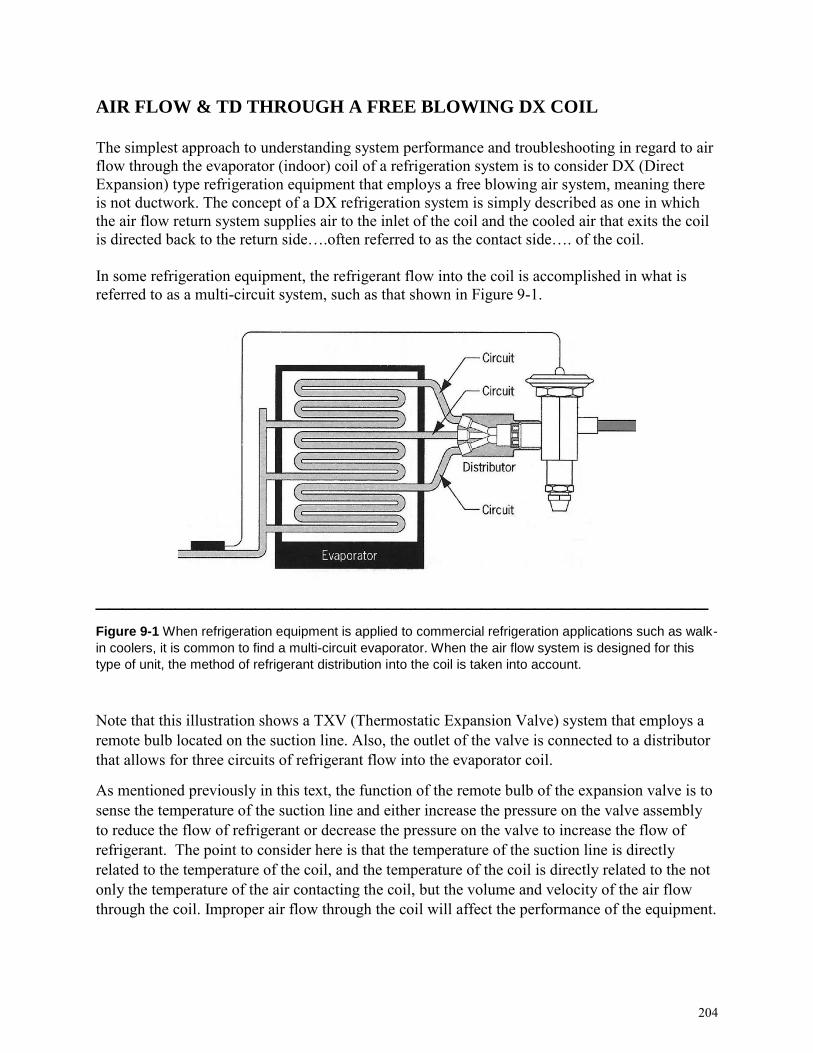
AIR FLOW & TD THROUGH A FREE BLOWING DX COIL
The simplest approach to understanding system performance and troubleshooting in regard to air flow through the evaporator (indoor) coil of a refrigeration system is to consider DX (Direct Expansion) type refrigeration equipment that employs a free blowing air system, meaning there is not ductwork. The concept of a DX refrigeration system is simply described as one in which the air flow return system supplies air to the inlet of the coil and the cooled air that exits the coil is directed back to the return side….often referred to as the contact side…. of the coil. In some refrigeration equipment, the refrigerant flow into the coil is accomplished in what is referred to as a multi-circuit system, such as that shown in Figure 9-1.
______________________________________________
Figure 9-1 When refrigeration equipment is applied to commercial refrigeration applications such as walk-
in coolers, it is common to find a multi-circuit evaporator. When the air flow system is designed for this
type of unit, the method of refrigerant distribution into the coil is taken into account.
Note that this illustration shows a TXV (Thermostatic Expansion Valve) system that employs a remote bulb located on the suction line. Also, the outlet of the valve is connected to a distributor that allows for three circuits of refrigerant flow into the evaporator coil.
As mentioned previously in this text, the function of the remote bulb of the expansion valve is to sense the temperature of the suction line and either increase the pressure on the valve assembly to reduce the flow of refrigerant or decrease the pressure on the valve to increase the flow of refrigerant. The point to consider here is that the temperature of the suction line is directly related to the temperature of the coil, and the temperature of the coil is directly related to the not only the temperature of the air contacting the coil, but the volume and velocity of the air flow through the coil. Improper air flow through the coil will affect the performance of the equipment.
204

UNIT 10
HVACR Air Flow System Evaluation Learning Objectives:
After studying this unit, you will:
1. Be able to identify the basic configurations of supply duct systems. 2. Understand how a manufacturer’s blower table is used in evaluating system performance. 3. Understand the concepts of static pressure, temperature split, and blower door testing.
Troubleshooting HVACR equipment boils down to evaluating the performance of an operating system, and comparing the results of refrigeration system pressure checks and air flow measurements accomplished to what would be considered normal in a particular situation. When a technician is evaluating equipment operation, some of the factors/questions that are considered from a general perspective are:
….Climate: Is it a high humidity or low humidity location? Extreme, or moderate temperatures?
….Air Distribution System: What type of supply air system is in use? Is there a return duct branch in every room or does the system rely on a central return?
….Building Structure: Is the design susceptible to undercooling or overheating because of weather variables such as the sun or wind? Any remodeling, maintenance, or repairs that could have an effect the performance of the equipment?
….Equipment Installation: If it’s a split system, were proper procedures followed to make sure the refrigerant charge was correct? Were the air handling system duct branches properly routed throughout the attic or crawl space? Was the ductwork properly sealed?
….Building Occupants: If it’s a residence, are the occupants unaware of problems with the structure or installation, and as a result, have unrealistic expectations about the ability of the equipment to maintain comfort in the building? If it’s an office or other commercial application, is the fact that different people have different levels of comfort the source of the complaint? Is the activity in the building responsible for extreme humidity or excessive levels of heat from equipment?
This unit will discuss the different types of air flow systems employed in comfort cooling equipment and evaluation procedures that relate to troubleshooting system problems.
228

SUPPLY AIR FLOW SYSTEM CONFIGURATIONS
From a practical perspective, there are three basic configurations of supply duct systems found in residential and some commercial applications: ….Trunk and Branch ….Radial ….Perimeter Loop Figure 10-1 shows a trunk and branch system that is commonly used in split systems in which a furnace acts as the air handler to provide heat in the winter, and, in conjunction with an indoor coil positioned in the main plenum and an outdoor condensing unit, provides cooling in the summer
____________________________________________________ Figure 10-1 One type of supply duct system found in residential and light commercial applications. It can
be referred to as a trunk and branch system or as an extended plenum system.
As this illustration shows, a main trunk takes off from the air handler plenum, and individual branches leave from different positions on the trunk to supply air to the different rooms or different locations in an open area in a building. One factor to keep in mind about the function of this type of duct system is that at a given point on the main trunk, the size of the ductwork is reduced. This change in size is implemented into the trunk design in order to promote air flow through the entire main trunk at a correct velocity.
Without this design procedure, the velocity of air flow through a long main trunk will degrade, resulting in insufficient air flow to the supply registers closest to the the air handler. And, since a supply register that is designed to provide a certain level of “throw” of air into the conditioned space depends on the correct volume and velocity of air being delivered through a branch, insufficient air flow will result in poor system performance.
229
HVACR Troubleshooting Fundamentals Refrigeration & Air Flow Systems
Appendix
A
Troubleshooting Problems
Student Review and Workbook Pages
Appendix A contains a series of troubleshooting problems in which the conditions found are presented. In accomplishing your diagnosis of the problems, you will find information in this text, and you may be required to do additional research beyond the text to complete an answer.
The illustration on the next page of this workbook shows an example of a fundamental small refrigeration system that will be used in some of the troubleshooting problems. It employs a finned evaporator, forced air condenser, and a pass of the condenser coil known as a Yoder Loop, which is designed to keep the cabinet temperature of the equipment above the dew point and prevent sweating. This type of modification is commonly used in place of an electric cabinet heater.
In addition to listing conditions related to refrigerant pressures, temperatures and static pressure measurements, some problems may include information on an electrical principle, the current draw of the equipment. This is a procedure accomplished with a clamp type electrical meter that allows for the measurement of the amount of amperes a motor is drawing. When a motor is operating properly and performing the amount of work it is designed to do, the current draw will be correct, also referred to as normal. Current draw may also be referred to as wattage.
To complete your workbook, explain your diagnoses by filling in the blanks in your workbook pages at the end of Appendix A.
260

Appendix A Illustration: A small refrigeration system that is commonly found in domestic refrigerators
and small reach-in equipment. It employs a forced-air finned evaporator, a forced-air, fan cooled
condenser, and a Yoder Loop that prevents sweating on the equipment cabinet. It also uses a capillary
tube metering device, a portion of which is attached to the suction line to make up a heat exchanger
assembly.
261

TROUBLESHOOTING PROBLEM #1
___________________________________________________
Figure A-1 This unit has higher than normal refrigeration pressures, a sweating and frosting suction line,
and excessive current draw. Explain your diagnosis in your workbook pages at the end of Appendix A.
262

TROUBLESHOOTING PROBLEM #2
____________________________________________________
Figure A-2 This unit has lower than normal system pressures and the compressor current draw is far
below normal. Explain your diagnosis in your workbook pages at the end of Appendix A.
263

TROUBLESHOOTING PROBLEM #3
____________________________________________________
Figure A-3 This unit has lower than normal refrigeration system pressures along with a higher than
normal current draw. Explain your diagnosis in your workbook pages at the end of Appendix A.
264

TROUBLESHOOTING PROBLEM #4
____________________________________________________
Figure A-4 The refrigeration system pressures in this unit are lower than they should be and the current
draw of the compressor is low. Explain your diagnosis in your workbook pages at the end of Appendix A.
265

TROUBLESHOOTING PROBLEM #5
____________________________________________________
Figure A-5 In this refrigeration system, the high side pressure is higher than normal and the low side
pressure is in a vacuum. Explain your diagnosis in your workbook pages at the end of Appendix A.
266

TROUBLESHOOTING PROBLEM #6
____________________________________________________
Figure A-6 This unit is operating in a vacuum on the low pressure side of the system while the high side
pressure is higher than normal. Explain your diagnosis in your workbook pages at the end of Appendix A.
267

TROUBLESHOOTING PROBLEM #7
____________________________________________________
Figure A-7 The low side pressure of this unit is in a vacuum, the high side pressure is slightly higher than
it should be, and the current draw of the compressor is lower than normal. Explain your diagnosis in your
workbook pages at the end of Appendix A.
268

TROUBLESHOOTING PROBLEM #8
____________________________________________________
Figure A-8 In this unit the differential between the low and high pressure sides of the system are closer
together than they should be, and the compressor current draw is below normal. Explain your diagnosis in
your workbook pages at the end of Appendix A.
269

TROUBLESHOOTING PROBLEM #9
____________________________________________________
Figure A-9 In this unit, the high side pressure is higher than it should be and the current draw of the
compressor is also excessive. Explain your diagnosis in your workbook pages at the end of Appendix A.
270

TROUBLESHOOTING PROBLEM #10
Now that we’ve looked into system evaluation and troubleshooting from a fundamental perspective relative to small refrigeration systems, we’ll look at some problems that involve other types of refrigeration, along with air flow systems.
Troubleshooting problem #10 involves a split system that has only been in service for two years, but there is a lot of history. Several service calls have occurred since the equipment was installed, and there is an on-going complaint from the customer that the system just doesn’t keep their ranch style home comfortable.
Several technicians have reported that they checked the refrigerant charge. One technician reported adjusting the OBD (Opposed Blade Damper) supply registers in an effort to achieve a better balance of air flow throughout the three bedrooms, living room, dining room and kitchen. Another technician replaced the indoor blower motor with an exact OEM replacement motor and capacitor. None of the previous service calls solved the problem and the customer complaint that the house often seems “sticky”. After considering the previous work performed, you elect to do a series of temperature tests on the duct system. Figure A-10 shows the test points at which you measured both the dry bulb and wet bulb temperatures in both the return and supply duct assemblies. When you calculate your results with a psychrometric chart, you note that there is a significant specific humidity change in the return duct system.
____________________________________________________Figure A-10 The equipment in this troubleshooting problem has a history, and the customer’s ongoing
complaint is that the house is always “sticky”.
Explain your diagnosis in your workbook pages at the end of Appendix A.
271

TROUBLESHOOTING PROBLEM #11
Troubleshooting problem #11 involves a two-year-old, 4 ton heat pump that was repaired in response to a “no cooling” complaint in the summer. At that time a failed reversing valve was replaced. The service record shows that the system was evacuated to 500 microns and the refrigerant charge was weighed in according to manufacturer’s specifications.
There were also two subsequent service calls in response to the customer’s complaint that the unit was not performing. In both of these situations, refrigerant was added to the system. Now, with the equipment operating in the heating mode, the customer is calling for service, and their explanation of the problem is that the unit seems to be running constantly and isn’t keeping the building comfortable.
Your decision to check the dry bulb temperatures of the air entering and leaving the outdoor coil shows that the system is incapable of achieving an acceptable Delta T. As your next step, you check the replaced reversing valve, and your temperature tests at points A and B show a Delta T of 13 degrees.
____________________________________________________
Figure A-11 Your temperature test at points A and B show a Delta T of 13 degrees. Explain your
diagnosis in your workbook pages at the end of Appendix A.
272

TROUBLESHOOTING PROBLEM #12
Troubleshooting problem #12 involves a 3-ton split system, and the customer’s complaint is that the house “just isn’t as comfortable as it used to be”. When they called for service, they asked for an estimate of what it would cost to get a “Freon” charge because they knew that the system has never been service since it was installed 7 years ago. They also told the dispatcher that the day before, they found that the filter was very dirty and they replaced it.
When you arrive, you confirm that the system is not able to maintain an acceptable comfort level in the building. Based on the information from the customer that no maintenance had been performed on the system since its installation, you perform dry bulb temperature tests of the air entering and leaving the indoor coil at points A and B shown in Figure A-12. The result of your temperature check leads you to perform a static pressure drop test across the indoor coil, providing the results shown. Explain your diagnosis in your workbook pages at the end of Appendix A
____________________________________________________
Figure A-12 Your dry bulb temperature tests in the system return at point A and downstream of the coil at
point B shows the differential. Your static pressure differential is also shown here. Explain your diagnosis
in your workbook pages at the end of Appendix A.
273

TROUBLESHOOTING PROBLEM #13
Troubleshooting problem #13 involves a 5-ton, R-22 rooftop air conditioning unit, and the customer’s complaint is that on days when the outdoor ambient temperature exceeds 90 degrees the system doesn’t keep the store comfortable even though it seems to be running continuously.
When you begin your evaluation of this situation, you determine that the evaporator and condenser coils are clean, that the air filters are clean, and that there is water in the condensate pan under the evaporator.
You also determine that the evaporator and condenser fan motor are operating normally and the compressor current draw is normal, and the liquid line sight glass is clear. There is no evidence, even after several hours of operation, that there is any shut-down due to safety controls. When you perform a temperature differential check across the filter drier, you find that there is not temperature drop across it that would indicate a restriction.
Figure A-13 shows additional details regarding the refrigerant pressures and temperatures you find.
____________________________________________________
Figure A-13 This illustration shows the operating pressures and temperatures you find when evaluating
the operation of a 5-ton, R-22 air conditioning system in a small convenience store. Explain your
diagnosis in your workbook pages at the end of Appendix A.
274

TROUBLESHOOTING PROBLEM #14
Troubleshooting problem #14 involves a new installation of a comfort cooling system in a ranch style home. This unit is a split system that employs a gas furnace for heat in the winter, with the air handler operating on a higher speed in the summer to provide cooling. The installation was accomplished just prior to the cooling season in early May and has never been operated in the heating mode.
It is now August, and the customer, who has complained from the beginning that the system is doesn’t keep the house comfortable, is calling for service again. Several previous service calls have not solved the situation, and the service orders of those calls report that refrigerant was added in an effort to get the system to operate more efficiently. The reports also mention that the supply registers have been adjusted repeatedly in an effort to balance the air flow in the individual rooms. Figure A-14 shows the configuration of the supply system in this equipment. The air flow system also employs a central return.
When you check the refrigerant pressures at the outdoor condensing unit you find both the high and low side pressures to be higher than normal. And, when you accomplish air flow checks with an anemometer at the supply registers you find the air flow insufficient. Your Total External Static Pressure test also shows that the system is not moving air in accordance with the data in the manufacturer’s blower table.
____________________________________________________
Figure A-14 This illustration shows the configuration of the supply duct system. Your anemometer tests
and static pressure testing shows insufficient air flow. Explain your diagnosis in your workbook pages at
the end of Appendix A.
275

TROUBLESHOOTING PROBLEM #15
Troubleshooting problem #15 involves a follow-up on a compressor diagnosis. Your role in this situation is to provide a second opinion. The technician who is asking you for a follow-up has limited experience with heat pump systems, and his diagnosis is that the compressor is inefficient. The customer’s complaint about this heat pump package unit that is just past the warranty period for the compressor is that the system is not cooling enough. The diagnosis that the compressor is not pumping was established based on the pressure readings found upon accessing the high and low pressure sides of the system at the points shown in Figure A-15.
When you arrive, you confirm that the compressor current draw is correct. And when you access the manufacturer’s charging charts and conduct a superheat evaluation, your finding is that the superheat significantly lower than it should be.
____________________________________________________
Figure A-15 This illustration shows a heat pump system in which the compressor current draw is correct
and consulting a manufacturer’s charging chart and conducting a superheat evaluation shows the
superheat to be significantly lower than it should be. Explain your diagnosis in your workbook pages at
the end of Appendix A.
276

Jim Johnson has been a full-time technician, as well as a full-time
trade school and community college instructor and administrator,
working in and around the refrigeration, HVACR, appliance, and
facility maintenance fields since 1973. He has facilitated
hundreds of training seminars, workshops and classes in the
HVACR electrical and refrigeration areas alone, as well as many
other workshops in other technical and non-technical areas.
His background includes a satellite training network for HVACR and appliance
technicians, and the development and presentation of more than 75 video training
programs. He has authored five textbooks and 10 technician handbooks.
He has been a columnist for trade magazines for more than 20 years, including
Indoor Comfort News, RSES Journal, ACHR News, ACHR News Extra Edition,
HVACR Today, and Marcone World Magazine, providing monthly troubleshooting
features and more than 500 feature articles.
He is a member of RSES, Certified as a Residential and Light Commercial Air
Balancing and Diagnostic Technician, and is certified in heat pumps. He also
holds multiple certifications in combustion analysis and carbon monoxide safety.
He is a registered proctor for NATE exams, and his workshops, HVAC training
videos, and e-book CD’s not only provide a simplified approach to learning about
troubleshooting and servicing heating and air conditioning equipment, they also
serve as an effective preparation for NATE certification exams.
Refrigeration & Air Flow Systems
HVACR Troubleshooting Fundamentals