Embed Size (px)
Citation preview

HTP MicroCut 875SC
Owner’s Manual
HTP America, Inc. · 180 Joey Drive · Elk Grove Village, IL 60007-1304
Phone: 847-357-0700 · Fax: 847-357-0744 · Web: www.usaweld.com

2
General Information
Thank you and congratulations on purchasing an HTP MicroCut 875SC. With many welding and cutting equipment options available on the market today, we appreciate your purchase, as well as the confidence you put into HTP through purchasing one of our products. The versatile MicroCut 875SC works with CNC plasma cutting tables—a first for HTP— with the addition of our optional CNC interface and 35’ machine torch. However, you can also operate the MicroCut 875SC manually with an 18’ hand torch. If you purchased the 18’ hand torch, you can always upgrade your machine to meet CNC plasma cutting table compatibility at a later date. As an added bonus, the hand torch and machine torch utilize the same consumables so you only need to keep on-hand and track-of a single style of replacement parts. We hope you enjoy working with your new plasma cutting machine! If you need help setting up or operating your plasma cutter, at any time, please feel free to contact us.
Index
General Information 2
Warranty 3
General Precautions & Safety Suggestions 4-6
Inspection 7
Plasma/Cooling Gas Connection 7
Electrical Connection 7
Front Panel Connections and Controls 8-9
Setup 9
Operation 10
Maintenance & Service 11
Hand Torch Parts Breakdown 12
Machine Torch Parts Breakdown 13
MicroCut 875SC Parts Breakdown 14
Wiring Diagram 15
3
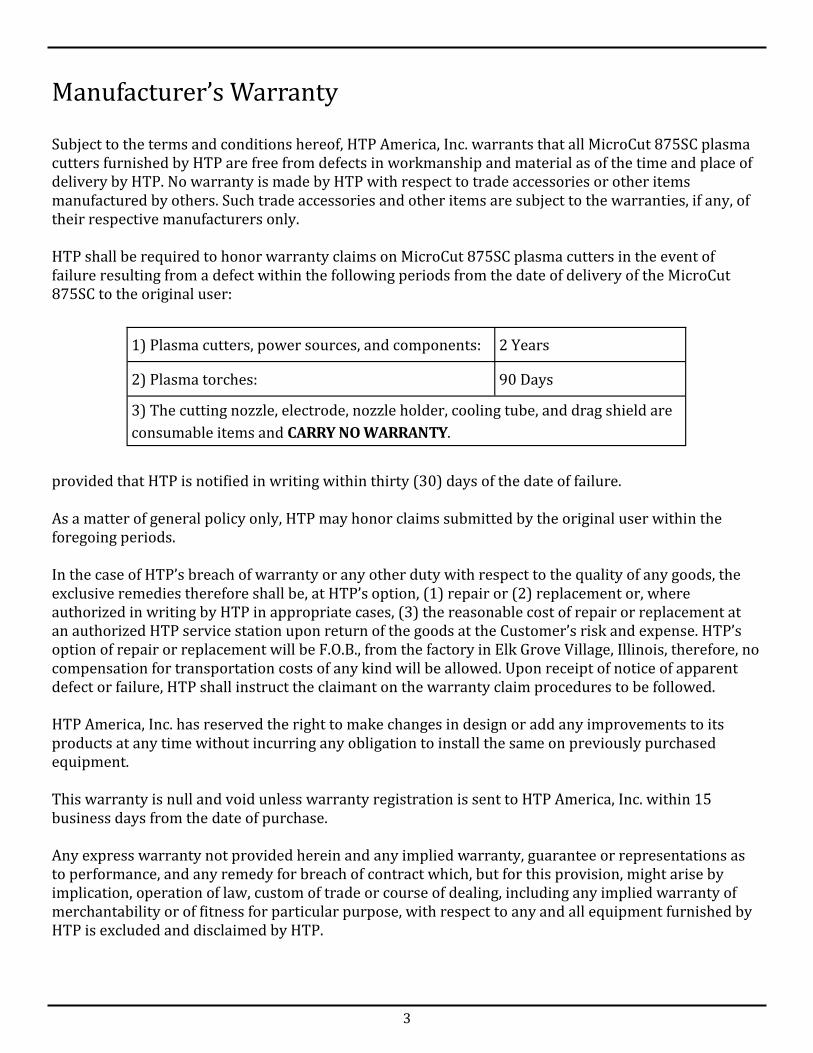
Subject to the terms and conditions hereof, HTP America, Inc. warrants that all MicroCut 875SC plasma cutters furnished by HTP are free from defects in workmanship and material as of the time and place of delivery by HTP. No warranty is made by HTP with respect to trade accessories or other items manufactured by others. Such trade accessories and other items are subject to the warranties, if any, of their respective manufacturers only. HTP shall be required to honor warranty claims on MicroCut 875SC plasma cutters in the event of failure resulting from a defect within the following periods from the date of delivery of the MicroCut 875SC to the original user: provided that HTP is notified in writing within thirty (30) days of the date of failure. As a matter of general policy only, HTP may honor claims submitted by the original user within the foregoing periods. In the case of HTP’s breach of warranty or any other duty with respect to the quality of any goods, the exclusive remedies therefore shall be, at HTP’s option, (1) repair or (2) replacement or, where authorized in writing by HTP in appropriate cases, (3) the reasonable cost of repair or replacement at an authorized HTP service station upon return of the goods at the Customer’s risk and expense. HTP’s option of repair or replacement will be F.O.B., from the factory in Elk Grove Village, Illinois, therefore, no compensation for transportation costs of any kind will be allowed. Upon receipt of notice of apparent defect or failure, HTP shall instruct the claimant on the warranty claim procedures to be followed. HTP America, Inc. has reserved the right to make changes in design or add any improvements to its products at any time without incurring any obligation to install the same on previously purchased equipment. This warranty is null and void unless warranty registration is sent to HTP America, Inc. within 15 business days from the date of purchase. Any express warranty not provided herein and any implied warranty, guarantee or representations as to performance, and any remedy for breach of contract which, but for this provision, might arise by implication, operation of law, custom of trade or course of dealing, including any implied warranty of merchantability or of fitness for particular purpose, with respect to any and all equipment furnished by HTP is excluded and disclaimed by HTP.
Manufacturer’s Warranty
1) Plasma cutters, power sources, and components: 2 Years
2) Plasma torches: 90 Days
3) The cutting nozzle, electrode, nozzle holder, cooling tube, and drag shield are
consumable items and CARRY NO WARRANTY.

4
General Precautions & Safety Suggestions
HTP America values your safety and the safety of those around you. Please read, follow, and save the following safety precautions and operating instructions in order to maintain a safe work environment and to ensure proper handling of all equipment. On Reading the Owner’s Manual and Operating Instructions Thoroughly read the Owner’s Manual and Operating Instructions prior to installing,
operating, or servicing equipment.
Only allow qualified individuals to operate,
maintain, and repair equipment. Maintain a dry working environment and
protect all cords from water, oil, and grease. When not operating equipment, disengage
power by turning off and unplugging equipment.
Do not operate equipment with damaged parts; repair or replace damaged parts immediately.
Do not operate equipment without all protective panels and covers in place. In fact, do not ever remove panels with equipment on and/or connected to a power supply.
During operation, keep all individuals, other than the operator, away from the work area.
Plasma Cutting Hazards
Risk of Electric Shock
Do not touch live electrical parts; live electrical
parts can cause electric shock, which results in serious injury, such as severe burns, or even death.
When you power the equipment on, all circuits, including the input power circuit and equipment internal circuits, become live.
Properly ground all equipment. Do not touch parts when in contact with the
work or ground.
Insulate yourself from the work and ground
using dry insulating mats or covers big enough to prevent any physical contact with the work or ground.
Wear dry, insulating gloves and body protection.
Turn off power before checking, cleaning, or changing torch parts.
Turn equipment off and disconnect from power supply before servicing.
Inspect input power cord, plasma torch, and ground cable for damage or exposed wiring. If you detect exposed wiring, discontinue use and replace cord promptly.
In order to reduce the risk of cord damage and electric shock, protect all cords from hot metal and sparks.
Do not wrap torch cable around your body.
Significant DC Voltage Exists on Internal Parts of Inverter Power Sources Even After Removal of Input Power. The input capacitors should read zero (0)
volts before you touch any parts. After turning off the power and disconnecting the equipment from the input power supply, test the voltage on the input capacitors according to the instructions in the Maintenance section of the Owner’s Manual.
WARNING!
5
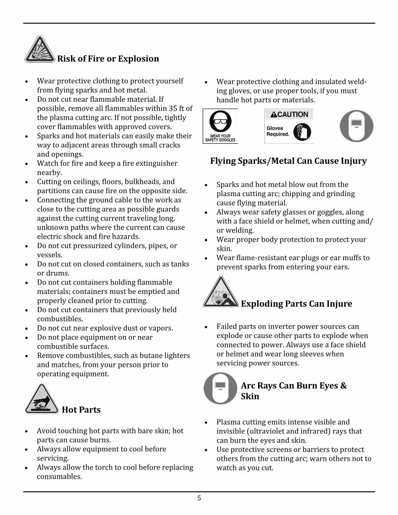
Risk of Fire or Explosion
Wear protective clothing to protect yourself
from flying sparks and hot metal. Do not cut near flammable material. If
possible, remove all flammables within 35 ft of the plasma cutting arc. If not possible, tightly cover flammables with approved covers.
Sparks and hot materials can easily make their way to adjacent areas through small cracks and openings.
Watch for fire and keep a fire extinguisher nearby.
Cutting on ceilings, floors, bulkheads, and partitions can cause fire on the opposite side.
Connecting the ground cable to the work as close to the cutting area as possible guards against the cutting current traveling long, unknown paths where the current can cause electric shock and fire hazards.
Do not cut pressurized cylinders, pipes, or vessels.
Do not cut on closed containers, such as tanks or drums.
Do not cut containers holding flammable materials; containers must be emptied and properly cleaned prior to cutting.
Do not cut containers that previously held combustibles.
Do not cut near explosive dust or vapors. Do not place equipment on or near
combustible surfaces. Remove combustibles, such as butane lighters
and matches, from your person prior to operating equipment.
Hot Parts
Avoid touching hot parts with bare skin; hot parts can cause burns.
Always allow equipment to cool before servicing.
Always allow the torch to cool before replacing consumables.
Wear protective clothing and insulated weld-ing gloves, or use proper tools, if you must handle hot parts or materials.
Flying Sparks/Metal Can Cause Injury
Sparks and hot metal blow out from the
plasma cutting arc; chipping and grinding cause flying material.
Always wear safety glasses or goggles, along with a face shield or helmet, when cutting and/or welding.
Wear proper body protection to protect your skin.
Wear flame-resistant ear plugs or ear muffs to prevent sparks from entering your ears.
Exploding Parts Can Injure
Failed parts on inverter power sources can
explode or cause other parts to explode when connected to power. Always use a face shield or helmet and wear long sleeves when servicing power sources.
Arc Rays Can Burn Eyes & Skin
Plasma cutting emits intense visible and
invisible (ultraviolet and infrared) rays that can burn the eyes and skin.
Use protective screens or barriers to protect others from the cutting arc; warn others not to watch as you cut.

6
Wear protective clothing made from durable,
flame-resistant material (leather or wool) and foot protection.
Wear a helmet or face shield with the correct filter shade to protect your face and eyes when cutting or watching someone else cut. ANSI Z49.1 (see Safety Standards) suggests a #9 shade (with a #8 minimum) for all cutting currents less than 300 amperes. Z49.1 adds that lighter filter shades may be used when the arc is hidden by the workpiece. As this is normally the case with low cutting currents, the shades suggested in Table 1 are provided for the operator’s convenience.
Table 1
Cutting Current in Amps Min. Shade Level
Below 20 #4
20-40 #5
40-60 #6
60-80 #7
Harmful Fumes
Plasma cutting produces fumes and gases; breathing these fumes and gases can be hazardous to your health. Keep your head out of fumes; do not breathe
the fumes. If cutting inside, ventilate the area and/or use
an exhaust system at the arc to remove cutting fumes and gases.
Do not work in confined spaces. When cutting in poorly ventilated areas, use an approved respirator.
Read the Material Safety Data Sheet (MSDS) and the manufacturers instructions for metals to be cut, as well as for coating and cleaners used.
Do not cut in locations near degreasing, cleaning, or spraying operations. The heat and rays of the arc can react with vapors and form highly toxic and/or irritating gases.
Do not cut coated metals, such as galvanized,
lead, or cadmium plated steel, unless you remove the coating from the workpiece, the area is well ventilated, or you are wearing an approved respirator. The coating and any metals containing these elements can give off toxic fumes when cut.
Do not cut containers holding toxic or reactive materials or containers that previously held toxic or reactive material; the containers must be emptied and properly cleaned first.
On Overuse & Overheating
Always follow the rated duty cycle of
equipment and allow sufficient cooling periods.
Ensure adequate airflow to all equipment to avoid overheating.
Gas Cylinders Can Explode
Gas cylinders can explode if damaged due to high pressure. Use caution when engaging in metalworking processes near gas cylinders. Protect gas cylinders from excessive heat,
mechanical shocks, slag, open flame, sparks, and welding/cutting arcs.
Install cylinders in an upright position, and secure cylinders to prevent falling or tipping.
Keep cylinders away from cutting or other electrical circuits.
Never allow contact between plasma torches and gas cylinders.
Do not cut on gas cylinders. Keep cylinder cap over valve except when in
use or connected for use.
Magnetic Fields Can Affect Pacemakers
If you wear a pacemaker, consult your doctor before going near plasma cutting operations.

7
Inspection
Plasma/Cooling Gas Connection
After receiving your MicroCut 875SC and removing from package, please inspect unit for concealed damage. All claims for loss or damage must be filed by the purchaser with the freight carrier. Please ensure the air supply inlet at the back of the unit is free of packaging materials. Packaging materials within the air supply inlet will obstruct air flow to the torch.
The MicroCut 875SC uses compressed air as both the plasma gas and the cooling gas. Water and oil in the air reduces the lifespan of your plasma torch and reduces the quality of your cuts. Damage incurred due to water and oil entering your plasma cutting system from the air supply line is not covered under warranty. While the MicroCut 875SC comes with an air filter/regulator, we suggest adding a desiccant dryer to your compressor. HTP offers two desiccant dryer/filter systems—the HTP Super Dry (Fig. 1, Part# 25300) and the HTP Max Dry (Fig. 2, Part# 25310-2). The HTP Super Dry is a disposable air dryer that uses a desiccant to remove moisture from the air. When the desiccant turns from blue to white, replace the air dryer. The HTP Max Dry features a five stage filtration process and includes reusable desiccant. When the desiccant turns from blue to a clear orange color, simply pour the desiccant on a baking sheet, place in the oven, and bake for about an hour or until the desiccant turns blue once again.
Fig. 1: HTP Super Dry,
Part# 25300
Fig. 2: HTP Max Dry, Part# 25310-2
Electrical Connection
The MicroCut 875SC operates off of a 220 volt (+/-20%) single phase input power supply, wired for a minimum of 30 amps. Only qualified electricians should perform electrical connections and all electrical connections must be made in accordance with the National Electrical Code and local codes and ordinances. When fitting your MicroCut 875SC with a power plug, the ground (yellow-green or green) wire must be connected to the ground, otherwise serious injury or death may result. Never connect the ground (yellow-green or green) wire to an input (hot) terminal, and never connect the input (blue and brown) wires to the ground terminal. We recommend installing a fusible line disconnect switch in the input power circuit of the MicroCut 875SC, which allows you to safely and easily remove all input electrical power prior to inspecting or servicing your plasma cutter. Before making a connection between the MicroCut 875SC and the input power supply, always ensure that the main power switch (Fig. 3, #8) is in the “Off” position or open the line disconnect switch.

8
Front Panel Connections & Controls
1
5
4
3
2
6 7
8
9
10
1) Plasma Torch Receptacle: Connection for the plasma cutting torch. If installed incorrectly, the cutter will not operate.
2) Cutting Current Adjustment: Controls the cutting amperage of the MicroCut 875SC. Infinitely variable from 30 to 55 amps.
3) Safety Alarm LED: LED illuminates red when you power on the MicroCut 875SC. Pressing the reset button (#7) turns the Safety Alarm LED off. If the Safety Alarm LED does not turn off after pressing the reset button, either the plasma torch is installed incorrectly, the consumables are not installed correctly, or the air pressure is set too low.
4) Thermo Switch LED: LED illuminates yellow if you exceed the duty cycle (40% at 55 amps) of the MicroCut 875SC. If you exceed the duty cycle of the cutter, leave the machine on, allowing the cooling fan to run. When the cutter cools, the Thermo Switch LED will turn off.
5) Air Pressure LED: LED illuminates green when properly connected to an air supply. The pressure gauge on the regulator should read above 70 psi; if the air pressure falls below 70 psi, the Air Pressure LED will shut off and the Safety Alarm LED will turn on, illuminating red.
11
Fig. 3
9
6) Input Power LED: LED illuminates green when the MicroCut 875SC is properly connected to a 220 volt input power supply and the Power Switch (#8) is turned on.
7) Reset Button: When you turn on the MicroCut 875SC, the Safety Alarm LED (#3) illuminates red. If the MicroCut 875SC is properly connected to a power supply, the air supply is sufficient, and the torch is installed correctly, pressing the Reset Button will turn off the Safety Alarm LED and you can begin cutting.
8) Power Switch: Turning the Power Switch on will supply 220 volts of power to your MicroCut 875SC. When you finish working with the plasma cutter, turn the Power Switch off.
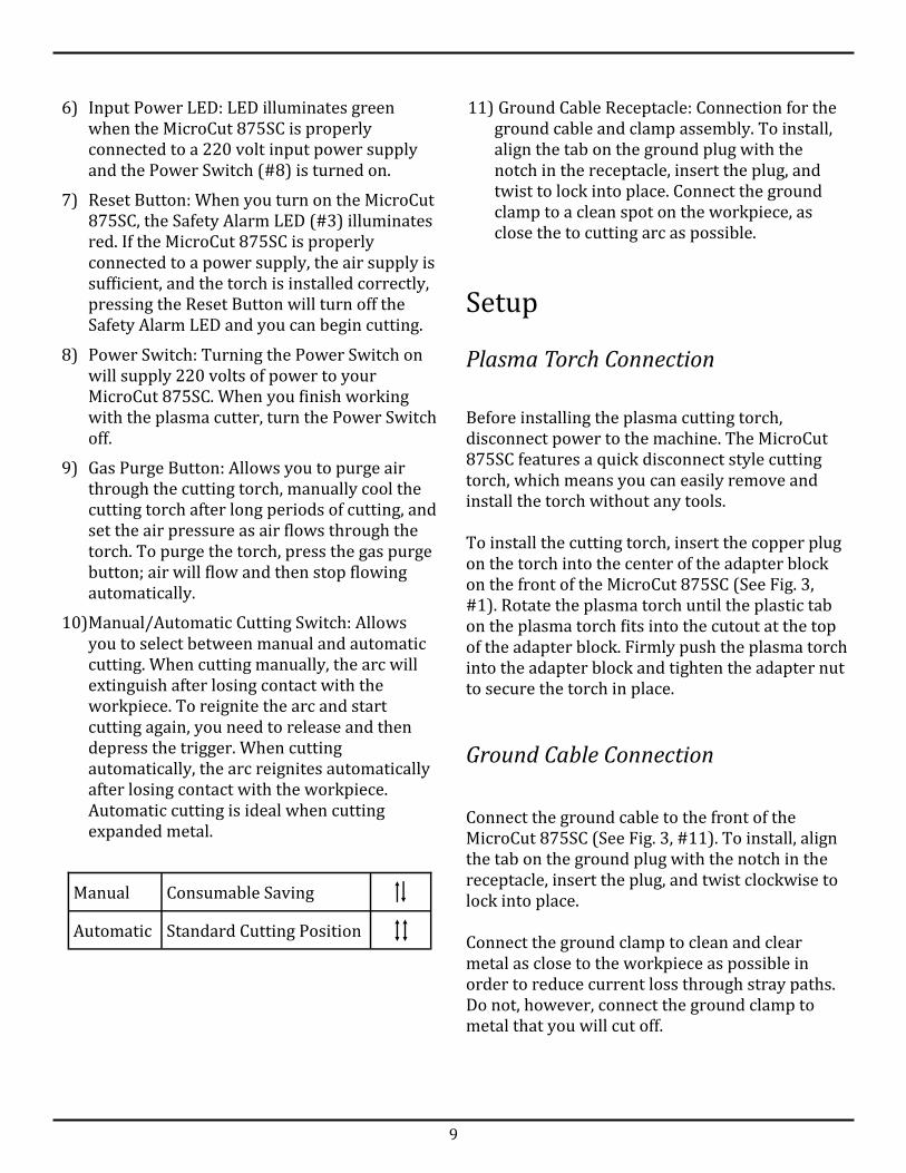
9) Gas Purge Button: Allows you to purge air through the cutting torch, manually cool the cutting torch after long periods of cutting, and set the air pressure as air flows through the torch. To purge the torch, press the gas purge button; air will flow and then stop flowing automatically.
10) Manual/Automatic Cutting Switch: Allows you to select between manual and automatic cutting. When cutting manually, the arc will extinguish after losing contact with the workpiece. To reignite the arc and start cutting again, you need to release and then depress the trigger. When cutting automatically, the arc reignites automatically after losing contact with the workpiece. Automatic cutting is ideal when cutting expanded metal.
Setup
Plasma Torch Connection
Before installing the plasma cutting torch, disconnect power to the machine. The MicroCut 875SC features a quick disconnect style cutting torch, which means you can easily remove and install the torch without any tools. To install the cutting torch, insert the copper plug on the torch into the center of the adapter block on the front of the MicroCut 875SC (See Fig. 3, #1). Rotate the plasma torch until the plastic tab on the plasma torch fits into the cutout at the top of the adapter block. Firmly push the plasma torch into the adapter block and tighten the adapter nut to secure the torch in place.
Ground Cable Connection
Connect the ground cable to the front of the MicroCut 875SC (See Fig. 3, #11). To install, align the tab on the ground plug with the notch in the receptacle, insert the plug, and twist clockwise to lock into place. Connect the ground clamp to clean and clear metal as close to the workpiece as possible in order to reduce current loss through stray paths. Do not, however, connect the ground clamp to metal that you will cut off.
Manual Consumable Saving
Automatic Standard Cutting Position
11) Ground Cable Receptacle: Connection for the ground cable and clamp assembly. To install, align the tab on the ground plug with the notch in the receptacle, insert the plug, and twist to lock into place. Connect the ground clamp to a clean spot on the workpiece, as close the to cutting arc as possible.

10
Operation
Please read and understand the operating instructions prior to working with your MicroCut 875SC. 1) Wear the correct eye protection and clothing,
and follow all safety suggestions. 2) Connect the MicroCut 875SC to a clean, dry
source of compressed air. Set the regulator on the back of the machine to 70 psi.
3) Connect the MicroCut 875SC to a 220 volt power supply (See Electrical Connection on Pg. 7). Turn the Power Switch (Fig. 3, #8) on. The Input Power LED (Fig. 3, #6) will illuminate green, the Air Pressure LED (Fig. 3, #5) will illuminate green, and the Safety Alarm LED (Fig. 3, #3) will illuminate red. Press the Reset Button (Fig. 3, #7). As long as you properly connected the MicroCut 875SC to a power supply, connected a sufficient air supply, and installed the torch and torch consumables correctly, the Reset Button will turn off the Safety Alarm LED and allow you to start cutting.
4) Connect the ground clamp to the workpiece as close to the cutting arc as possible.
5) Using the Cutting Current Adjustment knob (Fig. 3, #2) select the output current or output amperage desired. You should base this setting off the type and thickness of the material you plan to cut.
6) When ready to cut, place the cutting torch on the edge of the material and depress the trigger on the torch handle. The plasma arc will start immediately. With the plasma arc perpendicular to the workpiece, begin to move the plasma torch in the desired direction and at a speed in which the plasma arc bends anywhere from 5 to 15 degrees. The sparks should shoot out beneath the workpiece. If the sparks shoot up from the workpiece, slow down and/or adjust the output current. When you finish cutting, release the trigger to extinguish the plasma arc. Please note that air will continue to flow from the torch for an additional 15 seconds to cool the plasma torch.
Manual Piercing
When cutting thicker materials, hold the plasma torch at an angle and slightly off the workpiece. If you hold the torch perpendicular to the workpiece, slag, with no place to go, will flow up and damage the plasma torch consumables. Depress the torch trigger to start the plasma arc, and slowly roll the torch perpendicular to the workpiece. Once you pierce through the material completely, begin moving the torch in the desired direction as normal.
Cutting in Manual Mode
Cutting in Automatic Mode
Put the Manual/Automatic Cutting Switch (Fig. 3, #10) into the Manual (top) position. Make your cut as normal. When you reach the end of the workpiece, the arc will extinguish. In order to reestablish the arc, release and then depress the trigger once again.
Put the Manual/Automatic Cutting Switch (Fig. 3, #10) into the Automatic (bottom) position. Make your cut as normal. When you reach the end of the workpiece, the arc will extinguish but then restart when the torch once again meets metal.
CNC Piercing
You can also pierce materials up to 1/2” thick when connected to a CNC plasma cutting table. To pierce thick materials when connected to a CNC plasma cutting table, simply program the machine torch to begin cutting approximately 1/16” off of the material to be cut.

11
Plasma Torch
Warning! Turn off plasma cutter and disconnect from input power supply prior to servicing. Warning! Plasma torch parts reach high temperatures when cutting. To avoid the risk of burns, please wait for the plasma torch to cool completely prior to servicing or replacing consumables. Cleaning the torch consumables regularly helps maintain the life of the parts. Check the nozzles and electrodes for proper installation prior to each use. Check the air supply quality prior to each use, and make sure the air is set to at least 70 psi when cutting. As consumable parts, the nozzle and electrode wear out due to use. Check the nozzle and electrode regularly and replace when necessary.
Warning! Turn off plasma cutter and disconnect from input power supply prior to servicing. Remove cover and inspect the inside of power source once a month. Use an air compressor to remove any dust and debris. You can also remove dust and debris without removing the cover by blowing into the louvers located on the front and/or back of the power source. Removing dust and debris from inside the power source ensures the unimpeded operation of your plasma cutting equipment. Check the power cable and power cable connection regularly.
Power Source
Maintenance & Service For instance, when the hole in the cutting tip measures about 1/16” in diameter, replace the cutting tip; when the electrode develops a center pit measuring approximately 1/16” deep, replace the electrode. Keeping an eye on the life status of cutting tips and electrodes, and replacing these parts when necessary, ensures continual cutting efficiency. Check all other torch consumables for damage and replace if necessary. Check the torch handle for cracks and replace if necessary. If you notice any damage to the machine or torch cable assembly, contact HTP America, Inc. directly at 1-800-USA-WELD. ALL OTHER SERVICE SHOULD BE PERFORMED BY AUTHORIZED PERSONNEL ONLY.

12
B A C D E F G
Pictured Not Pictured
Part# Description Part# Description
A) CV0363 Drag Shield, Castle, 40-80A (3/4” Quality Cut, 1” Severance Cut)
CV0360 Drag Shield, 40-80A (1 Quality Cut, 1-3/16” Severance Cut)
B) PC0360 Nozzle Holder PD0360-10 Cutting Tip, 60A
C) PD0360-08 Cutting Tip, 40A BX0908 Trigger PCB
D) PE0360 Swirl Ring BW0908 Trigger PCB Housing
E) PR0360 Electrode, 40-80A BW0909 Safety Clip
F) FH1602 Cooling Tube EA1360 Safety Clip Spring
G) PF0360 Torch Head BW0147 Cable Support
H) BX0906 Trigger FY0043 Central Adaptor
I) TP0360 Handle 87180-HT Complete Torch
MicroCut 875SC Hand Torch Parts & Consumables
H
I
13
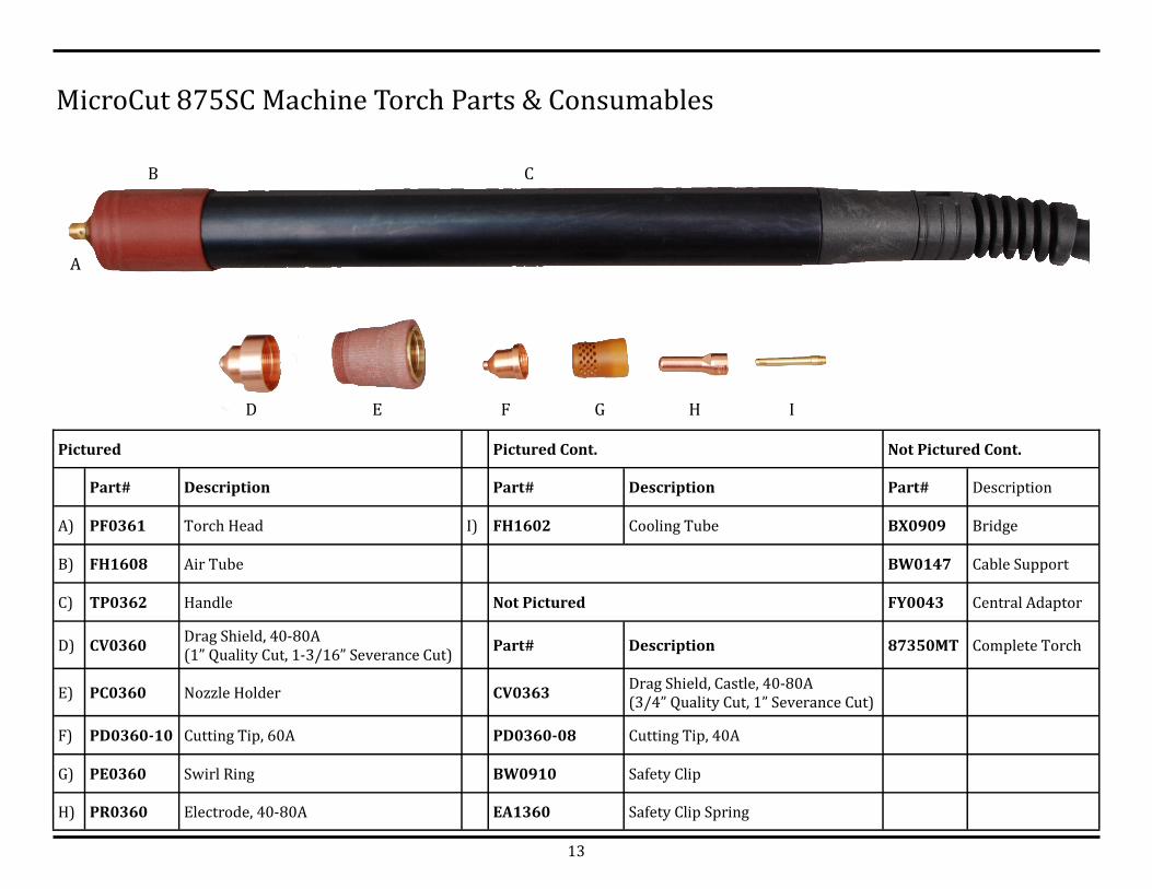
MicroCut 875SC Machine Torch Parts & Consumables
A
B
D E F G H I
Pictured Pictured Cont. Not Pictured Cont.
Part# Description Part# Description Part# Description
A) PF0361 Torch Head I) FH1602 Cooling Tube BX0909 Bridge
B) FH1608 Air Tube BW0147 Cable Support
C) TP0362 Handle Not Pictured FY0043 Central Adaptor
D) CV0360 Drag Shield, 40-80A (1” Quality Cut, 1-3/16” Severance Cut)
Part# Description 87350MT Complete Torch
E) PC0360 Nozzle Holder CV0363 Drag Shield, Castle, 40-80A (3/4” Quality Cut, 1” Severance Cut)
F) PD0360-10 Cutting Tip, 60A PD0360-08 Cutting Tip, 40A
G) PE0360 Swirl Ring BW0910 Safety Clip
H) PR0360 Electrode, 40-80A EA1360 Safety Clip Spring
C

14
# Description Part Number # Description Part Number # Description Part Number
1 Front Panel Label 66117 18 Thermostat 65023 35 — —
2 Amp Adjustment Knob 66106 19 Fan 64182 36 Pressure Switch 64032
3 On/Off Knob — 20 — — 37 Solenoid Valve 64393
4 — — 21 Fan Grid 66104 38 Primary PCB 61088
5 — — 22 Fuse Holder 64741 39 Switch 64132
6 Man/Auto Switch 64188 23 Label (Side Panels) 66116 40 — —
7 — — 24 Cover (Top & Right Side) 620595 41 — —
8 Front Panel 60104 25 Input Power Cable 64062 42 — —
9 Front Panel Holder 620593 26 Handle 66103 43 — —
10 On/Off Switch 64702 27 Regulator/Air Filter 63055 44 — —
11 — — 28 Fuse 64775 45 — —
12 — — 29 — — 46 Logic PCB 61316
13 Pilot Arc PCB 610833 30 — — 47 — —
14 XL 61307 31 Fuse PCB 61820 48 — —
15 Bottom Panel 62046 32 — — 49 PCB Line Filter 61168
16 Foot 66501 33 — — 50 Side Panel (Left) 62045
17 Secondary PCB 61267 34 Aux Transformer 65019
MicroCut 875SC Parts Breakdown
15
1
2
3
4
5
6
7
8
9
10
11
12
13
14
1
2
3
4
5
6
7
8
9
10
11
12
13
14
PCB
Primary
Inverter
61088800
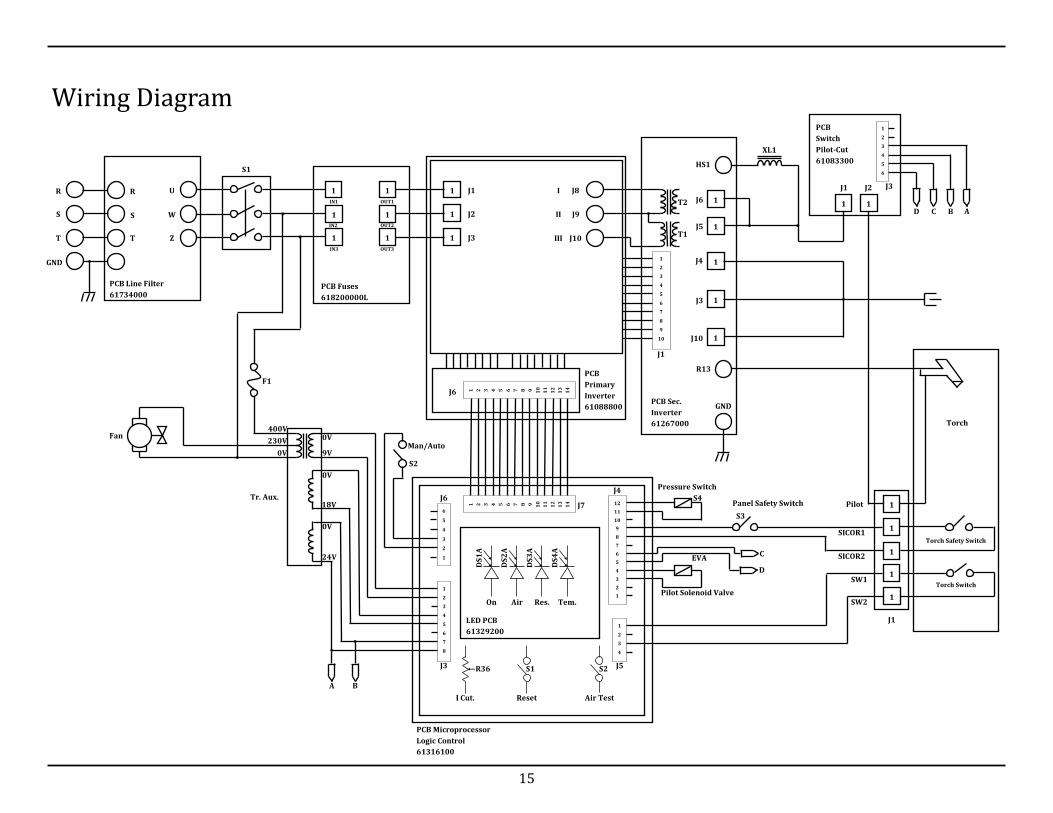
Wiring Diagram
1
1
1
1
1
1
1
1
1
PCB Fuses
618200000L
PCB Line Filter
61734000
PCB Sec.
Inverter
61267000
PCB
Switch
Pilot-Cut
61083300
Torch
PCB Microprocessor
Logic Control
61316100
J9
J8
J10
I
II
III
J1
J2
J3
R
S
T
U
W
Z
R
S
T
GND
IN1
IN2
IN3
OUT1
OUT2
OUT3
1
2
3
4
5
6
7
8
9
10
J6
J1
1
1
1
1
1 J6
J10
HS1
J3
R13
GND
J4
J5
J1 J2
1 1
1
2
3
4
5
6
12
11
10
9
8
7
6
5
4
3
2
1
1
2
3
4
A D C B
J3
1
1
1
1
1
6
5
4
3
2
1
1
2
3
4
5
6
7
8
Torch Safety Switch
Torch Switch
S1
T1
T2
XL1
J1
Pilot S4
S3
Pressure Switch
Panel Safety Switch
SICOR1
SICOR2
Pilot Solenoid Valve
EVA
SW1
SW2
J4
J5
J7 J6
J3
LED PCB
61329200
On Air Res. Tem.
DS
2A
DS
3A
DS
4A
DS
1A
R36
I Cut. Reset Air Test
S1 S2
C
D
A B
Man/Auto
S2
0V
9V
18V
24V
0V
0V
Tr. Aux.
Fan
F1
0V
230V
400V