Embed Size (px)
Citation preview
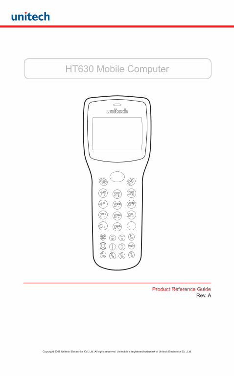
HT630 Mobile Computer
Product Reference GuideRev. A
Copyright 2008 Unitech Electronics Co., Ltd. All rights reserved. Unitech is a registered trademark of Unitech Electronics Co., Ltd.
Copyright 2008 Unitech Electronics Co., Ltd. All rights reserved. Unitech is a registered trademark of Unitech Electronics Co., Ltd.
2
Preface
About This Manual
This manual explains how to install, operate and maintain the Unitech HT630 Mobile Computer.
No part of this publication may be reproduced or used in any form without permission in writing from the manufacturer. This includes electronic or mechanical means, such as photocopying, recording, or information storage and retrieval systems. The material in this manual is subject to change without notice.
© Copyright 2009 Unitech Electronics Co., Ltd. All rights reserved.
All product names mentioned in this manual may be trademarks or registered trademarks of their respective companies and are hereby acknowledged.
SupportUnitech’s professional support team is available to quickly answer your questions or technical-related issues. Should an equipment problem occur, please contact the Unitech regional service representatives nearest you. For complete contact information, please visit the Web sites listed below.
UTA (USA, Canada) http://www.ute.com
UTA (Latin America) http://latin.ute.com
Copyright 2008 Unitech Electronics Co., Ltd. All rights reserved. Unitech is a registered trademark of Unitech Electronics Co., Ltd.
3
Notices General Precautions
• Before using this product be sure to read through this manual. After reading, please keep the manual in a safe place for future reference.• The information contained is subject to change without notice.• Unitech is not responsible for any operational results regardless of missing information, errors or any misprinting in this manual.• Unitech is not responsible for problems created as a result of using options and consumables not officially approved.• This product is designed for servicing at an Authorized Service Center. Other than routine maintenance described in this manual, the user should not attempt to repair, service or disassemble this product.• Incorrect operation, handling, improper supplies and operating environments may cause damage or otherwise affect the proper operation of this product. Such actions invalidate the product warranty.
Battery Notice
• This unit is equipped with a Lithium-Ion battery pack and backup battery. Although charged Lithium-Ion batteries may be left unused for several months, their capacity may be depleted due to build up of internal resistance. If this happens they will require recharging prior to use. Lithium-Ion batteries may be stored at temperatures between -4°F to 140°F, however they may be depleted more rapidly at the high end of this range. It is recommended to store batteries within normal room temperature.

Copyright 2008 Unitech Electronics Co., Ltd. All rights reserved. Unitech is a registered trademark of Unitech Electronics Co., Ltd.
4
Chapter 1Introduction
Overview . . . . . . . . . . . . . . . . . . . . . . . . . . . . . . . . . . . . . . . . . . . . . . . . . . . . . . . . 6Support . . . . . . . . . . . . . . . . . . . . . . . . . . . . . . . . . . . . . . . . . . . . . . . . . . . . . . . . . 6Customized HT630 . . . . . . . . . . . . . . . . . . . . . . . . . . . . . . . . . . . . . . . . . . . . . . . . 6Technical specifications . . . . . . . . . . . . . . . . . . . . . . . . . . . . . . . . . . . . . . . . . . . . 7In the box . . . . . . . . . . . . . . . . . . . . . . . . . . . . . . . . . . . . . . . . . . . . . . . . . . . . . . . . 8Accessories . . . . . . . . . . . . . . . . . . . . . . . . . . . . . . . . . . . . . . . . . . . . . . . . . . . . . . 8Installing and Charging the Battery . . . . . . . . . . . . . . . . . . . . . . . . . . . . . . . . . . 9Installing the Battery . . . . . . . . . . . . . . . . . . . . . . . . . . . . . . . . . . . . . . . . . . . . . . 9Charging the Battery . . . . . . . . . . . . . . . . . . . . . . . . . . . . . . . . . . . . . . . . . . . . . 10Cradle . . . . . . . . . . . . . . . . . . . . . . . . . . . . . . . . . . . . . . . . . . . . . . . . . . . . . . . . . . 11Interface Ports . . . . . . . . . . . . . . . . . . . . . . . . . . . . . . . . . . . . . . . . . . . . . . . . . . . 12USB Connection . . . . . . . . . . . . . . . . . . . . . . . . . . . . . . . . . . . . . . . . . . . . . . . . . 12Using the Keypad . . . . . . . . . . . . . . . . . . . . . . . . . . . . . . . . . . . . . . . . . . . . . . . . 14Numeric Mode . . . . . . . . . . . . . . . . . . . . . . . . . . . . . . . . . . . . . . . . . . . . . . . . . . . 15COMMAND Mode . . . . . . . . . . . . . . . . . . . . . . . . . . . . . . . . . . . . . . . . . . . . . . . . 15ALPHA Mode . . . . . . . . . . . . . . . . . . . . . . . . . . . . . . . . . . . . . . . . . . . . . . . . . . . . 15Triggering Scanner Module . . . . . . . . . . . . . . . . . . . . . . . . . . . . . . . . . . . . . . . . 16Application Development Environment . . . . . . . . . . . . . . . . . . . . . . . . . . . . . . 16JobGen Plus . . . . . . . . . . . . . . . . . . . . . . . . . . . . . . . . . . . . . . . . . . . . . . . . . . . . 16
Chapter 2Power System
Power System . . . . . . . . . . . . . . . . . . . . . . . . . . . . . . . . . . . . . . . . . . . . . . . . . . 17Main Power . . . . . . . . . . . . . . . . . . . . . . . . . . . . . . . . . . . . . . . . . . . . . . . . . . . . . 17Backup Power . . . . . . . . . . . . . . . . . . . . . . . . . . . . . . . . . . . . . . . . . . . . . . . . . . . 17Power Low Indication . . . . . . . . . . . . . . . . . . . . . . . . . . . . . . . . . . . . . . . . . . . . . 18Main Battery . . . . . . . . . . . . . . . . . . . . . . . . . . . . . . . . . . . . . . . . . . . . . . . . . . . . 18Lithium Backup Battery . . . . . . . . . . . . . . . . . . . . . . . . . . . . . . . . . . . . . . . . . . . 18Battery Replacement . . . . . . . . . . . . . . . . . . . . . . . . . . . . . . . . . . . . . . . . . . . . . 18Recharging the Battery . . . . . . . . . . . . . . . . . . . . . . . . . . . . . . . . . . . . . . . . . . . 19Charging Consideration . . . . . . . . . . . . . . . . . . . . . . . . . . . . . . . . . . . . . . . . . . . 19Effects of Overcharging Batteries . . . . . . . . . . . . . . . . . . . . . . . . . . . . . . . . . . . 19Storage and Safety Precautions . . . . . . . . . . . . . . . . . . . . . . . . . . . . . . . . . . . . 19
Table of Contents
Copyright 2008 Unitech Electronics Co., Ltd. All rights reserved. Unitech is a registered trademark of Unitech Electronics Co., Ltd.
5
Chapter 3Operation
Overview . . . . . . . . . . . . . . . . . . . . . . . . . . . . . . . . . . . . . . . . . . . . . . . . . . . . . . . 20Ready Mode . . . . . . . . . . . . . . . . . . . . . . . . . . . . . . . . . . . . . . . . . . . . . . . . . . . . . 21User Mode and System Commands . . . . . . . . . . . . . . . . . . . . . . . . . . . . . . . . . 21Configure the HT630 in SET Command . . . . . . . . . . . . . . . . . . . . . . . . . . . . . . 24Date & Time - Setting the system clock and calendar . . . . . . . . . . . . . . . . . . . 24Scanner . . . . . . . . . . . . . . . . . . . . . . . . . . . . . . . . . . . . . . . . . . . . . . . . . . . . . . . . 24DISPLAY. . . . . . . . . . . . . . . . . . . . . . . . . . . . . . . . . . . . . . . . . . . . . . . . . . . . . . . . 25KEYPAD . . . . . . . . . . . . . . . . . . . . . . . . . . . . . . . . . . . . . . . . . . . . . . . . . . . . . . . . 25EXIT . . . . . . . . . . . . . . . . . . . . . . . . . . . . . . . . . . . . . . . . . . . . . . . . . . . . . . . . . . . 25Uploading and Downloading Files . . . . . . . . . . . . . . . . . . . . . . . . . . . . . . . . . . 26PTComm Manager . . . . . . . . . . . . . . . . . . . . . . . . . . . . . . . . . . . . . . . . . . . . . . . 26uTransfer . . . . . . . . . . . . . . . . . . . . . . . . . . . . . . . . . . . . . . . . . . . . . . . . . . . . . . . 27
Chapter 4Built-in Application - FormCaching
Overview . . . . . . . . . . . . . . . . . . . . . . . . . . . . . . . . . . . . . . . . . . . . . . . . . . . . . . . 28Specifications of FormCaching . . . . . . . . . . . . . . . . . . . . . . . . . . . . . . . . . . . . . 28How to Create a FormCaching . . . . . . . . . . . . . . . . . . . . . . . . . . . . . . . . . . . . . 30How to Run FormCaching . . . . . . . . . . . . . . . . . . . . . . . . . . . . . . . . . . . . . . . . . 30Default Setting of FormCaching . . . . . . . . . . . . . . . . . . . . . . . . . . . . . . . . . . . . 31
Chapter 5Warranty
Warranty. . . . . . . . . . . . . . . . . . . . . . . . . . . . . . . . . . . . . . . . . . . . . . . . . . . . . . . . 32Warranty and/or Repair Service. . . . . . . . . . . . . . . . . . . . . . . . . . . . . . . . . . . . . 32
Copyright 2008 Unitech Electronics Co., Ltd. All rights reserved. Unitech is a registered trademark of Unitech Electronics Co., Ltd.
6
Chapter 1
Introduction
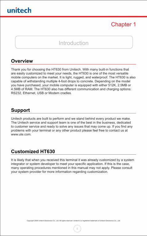
OverviewThank you for choosing the HT630 from Unitech. With many built-in functions that are easily customized to meet your needs, the HT630 is one of the most versatile mobile computers on the market. It is light, rugged, and waterproof. The HT630 is also capable of withstanding multiple 4-foot drops to concrete. Depending on the model you have purchased, your mobile computer is equipped with either 512K, 2.5MB or 4.5MB of RAM. The HT630 also has different communication and charging options: RS232, Ethernet, USB or Modem cradles.
SupportUnitech products are built to perform and we stand behind every product we make. The Unitech service and support team is one of the best in the business, dedicated to customer service and ready to solve any issues that may come up. If you find any problems with your terminal or any other product please feel free to contact us at www.ute.com.
Customized HT630It is likely that when you received this terminal it was already customized by a system integrator or system developer to meet your specific application. If this is the case, many operating procedures mentioned in this manual may not apply. Please consult your system provider for more information regarding customization.
Copyright 2008 Unitech Electronics Co., Ltd. All rights reserved. Unitech is a registered trademark of Unitech Electronics Co., Ltd.
7
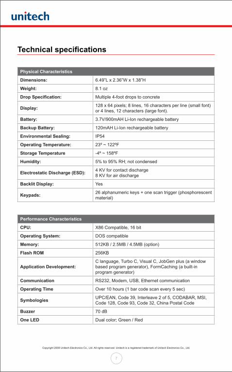
Technical specifications
Physical Characteristics
Dimensions: 6.49”L x 2.36”W x 1.38”H
Weight: 8.1 oz
Drop Specification: Multiple 4-foot drops to concrete
Display: 128 x 64 pixels; 8 lines, 16 characters per line (small font) or 4 lines, 12 characters (large font).
Battery: 3.7V/900mAH Li-Ion rechargeable battery
Backup Battery: 120mAH Li-Ion rechargeable battery
Environmental Sealing: IP54
Operating Temperature: 23º ~ 122ºF
Storage Temperature -4º ~ 158ºF
Humidity: 5% to 95% RH; not condensed
Electrostatic Discharge (ESD): 4 KV for contact discharge 8 KV for air discharge
Backlit Display: Yes
Keypads: 26 alphanumeric keys + one scan trigger (phosphorescent material)
Performance Characteristics
CPU: X86 Compatible, 16 bit
Operating System: DOS compatible
Memory: 512KB / 2.5MB / 4.5MB (option)
Flash ROM 256KB
Application Development: C language, Turbo C, Visual C, JobGen plus (a window based program generator), FormCaching (a built-in program generator)
Communication RS232, Modem, USB, Ethernet communication
Operating Time Over 10 hours (1 bar code scan every 5 sec)
Symbologies UPC/EAN, Code 39, Interleave 2 of 5, CODABAR, MSI, Code 128, Code 93, Code 32, China Postal Code
Buzzer 70 dB
One LED Dual color; Green / Red
Copyright 2008 Unitech Electronics Co., Ltd. All rights reserved. Unitech is a registered trademark of Unitech Electronics Co., Ltd.
8
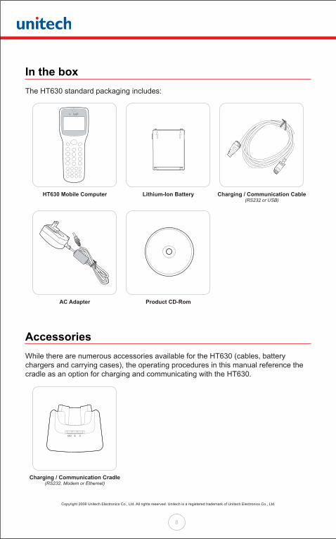
In the boxThe HT630 standard packaging includes:
AccessoriesWhile there are numerous accessories available for the HT630 (cables, battery chargers and carrying cases), the operating procedures in this manual reference the cradle as an option for charging and communicating with the HT630.
HT630 Mobile Computer
Charging / Communication Cradle(RS232, Modem or Ethernet)
AC Adapter
Lithium-Ion Battery
Product CD-Rom
Charging / Communication Cable(RS232 or USB)

Copyright 2008 Unitech Electronics Co., Ltd. All rights reserved. Unitech is a registered trademark of Unitech Electronics Co., Ltd.
9
Installing and Charging the BatteryOne Lithium-Ion battery is included with the HT630, and the battery must be charged before the device is ready for use.
Installing the BatteryUsing a coin or screw driver, unlock the battery door •
by turning the locking screw in a counterclockwise direction. Remove the battery door by lifting it off the HT630.
Before inserting the Lithium-Ion battery pack into • the HT630, turn the back-up battery switch to the “On” position.
Insert the battery so the gold contacts on the battery • line up with the contacts on the HT630. Then slide the locking tabs on the top of the battery into the open slots in the HT630 battery compartment. Once the locking tabs are securely in place, press the bottom half of the battery into the compartment. Then reinstall the battery door and tighten the screw to secure the door in place.
Back-up Battery Switch
Copyright 2008 Unitech Electronics Co., Ltd. All rights reserved. Unitech is a registered trademark of Unitech Electronics Co., Ltd.
10
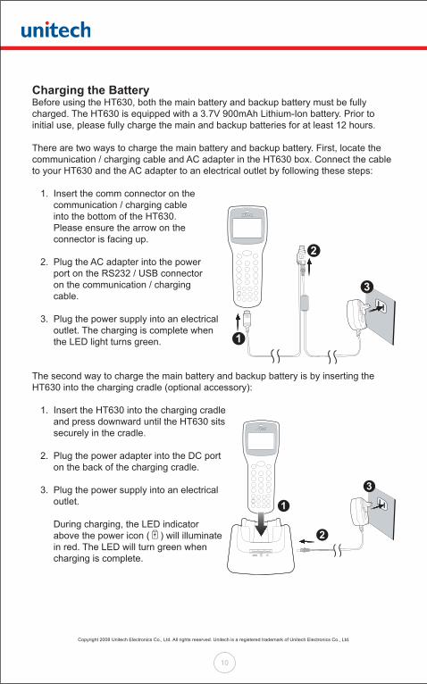
Charging the BatteryBefore using the HT630, both the main battery and backup battery must be fully charged. The HT630 is equipped with a 3.7V 900mAh Lithium-Ion battery. Prior to initial use, please fully charge the main and backup batteries for at least 12 hours.
There are two ways to charge the main battery and backup battery. First, locate the communication / charging cable and AC adapter in the HT630 box. Connect the cable to your HT630 and the AC adapter to an electrical outlet by following these steps:
1. Insert the comm connector on the communication / charging cable into the bottom of the HT630. Please ensure the arrow on the connector is facing up.
2. Plug the AC adapter into the power port on the RS232 / USB connector on the communication / charging cable.
3. Plug the power supply into an electrical outlet. The charging is complete when the LED light turns green.
The second way to charge the main battery and backup battery is by inserting the HT630 into the charging cradle (optional accessory): 1. Insert the HT630 into the charging cradle and press downward until the HT630 sits securely in the cradle.
2. Plug the power adapter into the DC port on the back of the charging cradle.
3. Plug the power supply into an electrical outlet.
During charging, the LED indicator above the power icon ( ) will illuminate in red. The LED will turn green when charging is complete.
3
2
1
2
1
3
Copyright 2008 Unitech Electronics Co., Ltd. All rights reserved. Unitech is a registered trademark of Unitech Electronics Co., Ltd.
11
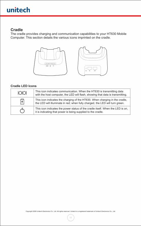
CradleThe cradle provides charging and communication capabilities to your HT630 Mobile Computer. This section details the various icons imprinted on the cradle.
Cradle LED Icons
This icon indicates communication. When the HT630 is transmitting data with the host computer, the LED will flash, showing that data is transmitting.
This icon indicates the charging of the HT630. When charging in the cradle, the LED will illuminate in red; when fully charged, the LED will turn green.
This icon indicates the power status of the cradle itself. When the LED is on, it is indicating that power is being supplied to the cradle.

Copyright 2008 Unitech Electronics Co., Ltd. All rights reserved. Unitech is a registered trademark of Unitech Electronics Co., Ltd.
12
Interface PortsThe HT630 communicates through the comm port located on the bottom of the unit. Connect the HT630 to a PC’s RS232 or USB port with the charging / communication cable. The cradle can be connected to a PC in the same fashion.
USB ConnectionTo use the USB connection between the HT630 and a PC, you must configure a USB driver. Follow the instructions to establish USB connectivity to a PC.
1. Insert the Product CD
Locate the Product CD included in your HT630 box, and insert it into your PC’s CD-ROM drive. The Product CD has the necessary USB drivers required for your HT630 and PC to communicate.
2. Connect the USB Cable
Locate the USB communication / charging cable in your HT630 box. Connect the cable to your HT630 and PC.
• Insert the comm connector into the bottom of the HT630.
• Insert the USB connector into a USB port on your PC.
• Plug the AC adapter into the power port on the USB connector.
• Plug the power supply into an electrical outlet.
3
2
1
3. Windows Detects Hardware
After connecting the HT630 to your PC with the USB cable, Microsoft Windows will alert you that it has “Found New Hardware”.
Microsoft Windows will then automatically launch the Hardware Update Wizard.
Copyright 2008 Unitech Electronics Co., Ltd. All rights reserved. Unitech is a registered trademark of Unitech Electronics Co., Ltd.
13
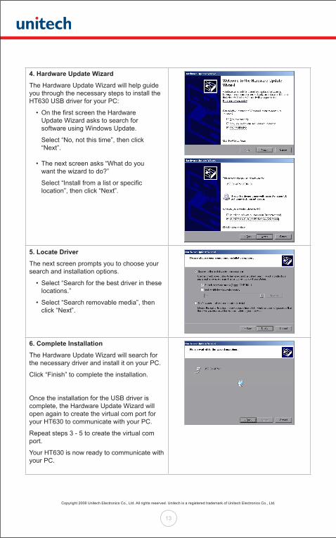
4. Hardware Update Wizard
The Hardware Update Wizard will help guide you through the necessary steps to install the HT630 USB driver for your PC:
• On the first screen the Hardware Update Wizard asks to search for software using Windows Update.
Select “No, not this time”, then click “Next”.
• The next screen asks “What do you want the wizard to do?”
Select “Install from a list or specific location”, then click “Next”.
5. Locate Driver
The next screen prompts you to choose your search and installation options.
• Select “Search for the best driver in these locations.”
• Select “Search removable media”, then click “Next”.
6. Complete Installation
The Hardware Update Wizard will search for the necessary driver and install it on your PC.
Click “Finish” to complete the installation.
Once the installation for the USB driver is complete, the Hardware Update Wizard will open again to create the virtual com port for your HT630 to communicate with your PC.
Repeat steps 3 - 5 to create the virtual com port.
Your HT630 is now ready to communicate with your PC.
Copyright 2008 Unitech Electronics Co., Ltd. All rights reserved. Unitech is a registered trademark of Unitech Electronics Co., Ltd.
14
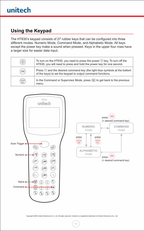
Using the KeypadThe HT630’s keypad consists of 27 rubber keys that can be configured into three different modes: Numeric Mode, Command Mode, and Alphabetic Mode. All keys except the power key make a sound when pressed. Keys in the upper four rows have a larger size for easier data input.
To turn on the HT630, you need to press the power key. To turn off the HT630, you will need to press and hold the power key for one second.
Press and the desired command key (the light blue symbols at the bottom of the keys) to set the keypad to output command functions.
In the Command or Supervisor Mode, press to get back to the previous menu.
Scan Trigger
Numeric
Alpha
Command
ALPHABETIC mode
NUMERIC mode
COMMAND mode
press press
press
press
(+ desired command key)
(+ desired command key)
Copyright 2008 Unitech Electronics Co., Ltd. All rights reserved. Unitech is a registered trademark of Unitech Electronics Co., Ltd.
15
Numeric ModeThe HT630 keypad is set to Numeric Mode after being powered on. In Numeric Mode, the cursor is a block and the keypad is mainly used to input numeric data and use the four function keys ( ).
COMMAND ModePress the command key to set the keypad to Command Mode. In Command Mode, the cursor sign is still the same and the keypad is mainly used to input special characters, make hot-key functions, and use F5-F8 as function keys.
ALPHA ModePress the alpha key to toggle between Numeric Mode keypad and Alpha Mode keypad. In the Alpha Mode, the cursor is an underscore sign and the keypad is available to input upper case letters. In Alpha Mode, every numeric key contains three individual characters. You need to press the key once to get the first character, twice to get the second character and three times to get the third character.
For example: • First press alpha key to switch the system to Alpha Mode, the cursor type will be changed from block to underscore.
• To enter ‘A’, press once.
• To enter “B”, press twice.
• To enter “C”, press three times.
Copyright 2008 Unitech Electronics Co., Ltd. All rights reserved. Unitech is a registered trademark of Unitech Electronics Co., Ltd.
16
Triggering Scanner ModuleThe HT630 can be used with a built-in laser scanner module to input data. The built-in decoder reads most bar code labels. Users should keep the laser window clean to prevent low reading rate of distorted bar code input signals.
Application Development Environment The HT630 provides DOS functions and device drivers for application development, including bar code decoding, keypad input, display output, serial input/output communication, real-time clock access and power management control.
The HT630 can be programmed by the Windows-based JobGen Plus program generation software or programmed by commonly used C compilers including Microsoft C, Borland C and Turbo C. An executable program generated by JobGen Plus or created by a compiler is downloaded to the HT630 and run on the unit.
JobGen PlusJobGen Plus is a Windows-based program generator that gives users a comprehensive terminal application development environment. With JobGen Plus, users can design an application program for the HT630 by simply drawing the data collection sequence on paper. The program requires minimal programming skills. For more detailed programming information, please refer to the HT630 Programming Reference Manual / JobGen Pro User’s Manual.

Copyright 2008 Unitech Electronics Co., Ltd. All rights reserved. Unitech is a registered trademark of Unitech Electronics Co., Ltd.
17
Chapter 2
Power System
Power System
Main PowerThe HT630 is powered by a rechargeable 3.7V 900mAH Lithium-Ion battery pack. The main battery should be sufficient for daily operation up to 10 hours (based on 1 bar code scan every 5 seconds). However, since actual operation requirements may vary, it is possible to get a shorter result than the estimated operating times.
Backup PowerA Lithium battery is used as the secondary power source to back up the data on the HT630. The RTC (real time clock chip) and RAM memory also help to prevent data loss.
Normally, the HT630 gets power from the main battery to back up the RTC and RAM. This also puts the backup battery in standby mode. When the main battery is removed or below the required level to back up the RAM and RTC properly, the power circuit of the HT630 automatically switches to the backup battery for power.
It is recommended to always keep the main battery charged. If the main battery loses charge, the backup battery is capable of storing data for up to 6 months. As long as the main battery is charged, you will not have to replace the backup battery. If you do replace the backup battery, all data stored on the device will be lost. All data must be backed up before replacing the backup battery.
Copyright 2008 Unitech Electronics Co., Ltd. All rights reserved. Unitech is a registered trademark of Unitech Electronics Co., Ltd.
18
Power Low Indication
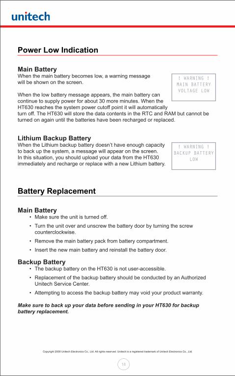
Main BatteryWhen the main battery becomes low, a warning message will be shown on the screen.
When the low battery message appears, the main battery can continue to supply power for about 30 more minutes. When the HT630 reaches the system power cutoff point it will automatically turn off. The HT630 will store the data contents in the RTC and RAM but cannot be turned on again until the batteries have been recharged or replaced.
Lithium Backup BatteryWhen the Lithium backup battery doesn’t have enough capacity to back up the system, a message will appear on the screen. In this situation, you should upload your data from the HT630 immediately and recharge or replace with a new Lithium battery.
Battery Replacement
Main Battery • Make sure the unit is turned off.
• Turn the unit over and unscrew the battery door by turning the screw counterclockwise.
• Remove the main battery pack from battery compartment.
• Insert the new main battery and reinstall the battery door.
Backup Battery • The backup battery on the HT630 is not user-accessible.
• Replacement of the backup battery should be conducted by an Authorized Unitech Service Center.
• Attempting to access the backup battery may void your product warranty.
Make sure to back up your data before sending in your HT630 for backup battery replacement.
! WARNING !MAIN BATTERY VOLTAGE LOW
! WARNING !BACKUP BATTERY
LOW
Copyright 2008 Unitech Electronics Co., Ltd. All rights reserved. Unitech is a registered trademark of Unitech Electronics Co., Ltd.
19
Recharging the Battery When the terminal shows the “Main Battery Low” message, the battery needs to be recharged (See ‘Charging the Battery’ in Chapter 1 of this manual). When the battery is fully charged, the LED light will turn green. Charging time typically takes two to three hours.
Charging ConsiderationIt is important to consider the temperature when charging the Lithium-Ion battery pack. The charging process is most efficient at normal room temperatures or slightly cooler. It is essential to charge the battery within the stated range of 32°F to 113°F (0°C to 45°C). Charging the battery outside of the specified range could damage the battery and shorten its life cycle.
Effects of Overcharging BatteriesOvercharging may occur when a Lithium-Ion rechargeable battery is continually charged for extended periods after it has reached full charge capacity. For example, a battery left to charge for several weeks may appear to have minimal capacity. This type of failure can be remedied by completely depleting the battery of power and then recharging it to full capacity.
This condition can be prevented by immediately unplugging the power cable when the unit reaches full charge, or by using the cradle to charge the batteries. The cradle starts the charge process in Quick Charge Mode and switches to Trickle Charge Mode when it detects the battery is fully charged. There is no risk of overcharging in Trickle Charge Mode.
Storage and Safety PrecautionsBatteries should be stored where there is no risk of accidental shortage or other damage. Although charged Lithium-Ion batteries may be left unused for several months, their capacity may be reduced due to back up and internal resistance. If this happens, they will require recharging prior to use. Lithium-Ion batteries may be stored at temperatures between -4°F and 158°F (-20°C to 70°C).
Copyright 2008 Unitech Electronics Co., Ltd. All rights reserved. Unitech is a registered trademark of Unitech Electronics Co., Ltd.
20
Chapter 3
Operation
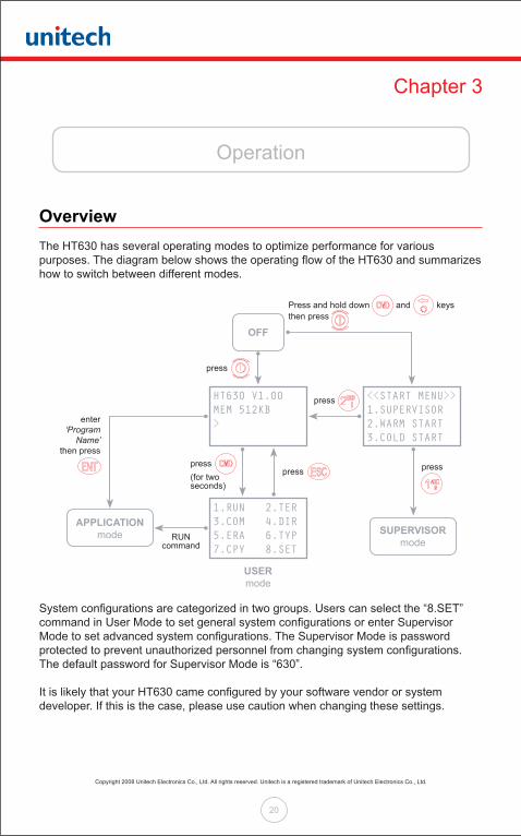
Overview The HT630 has several operating modes to optimize performance for various purposes. The diagram below shows the operating flow of the HT630 and summarizes how to switch between different modes.
System configurations are categorized in two groups. Users can select the “8.SET” command in User Mode to set general system configurations or enter Supervisor Mode to set advanced system configurations. The Supervisor Mode is password protected to prevent unauthorized personnel from changing system configurations. The default password for Supervisor Mode is “630”.
It is likely that your HT630 came configured by your software vendor or system developer. If this is the case, please use caution when changing these settings.
Press and hold down
enter ‘Program
Name’then press
OFF
APPLICATION mode
USER mode
SUPERVISOR mode
then press
press
press
press
presspress
RUNcommand
(for two seconds)
and keys
1.RUN 2.TER3.COM 4.DIR5.ERA 6.TYP7.CPY 8.SET
HT630 V1.00MEM 512KB>
<<START MENU>>1.SUPERVISOR2.WARM START3.COLD START
Copyright 2008 Unitech Electronics Co., Ltd. All rights reserved. Unitech is a registered trademark of Unitech Electronics Co., Ltd.
21
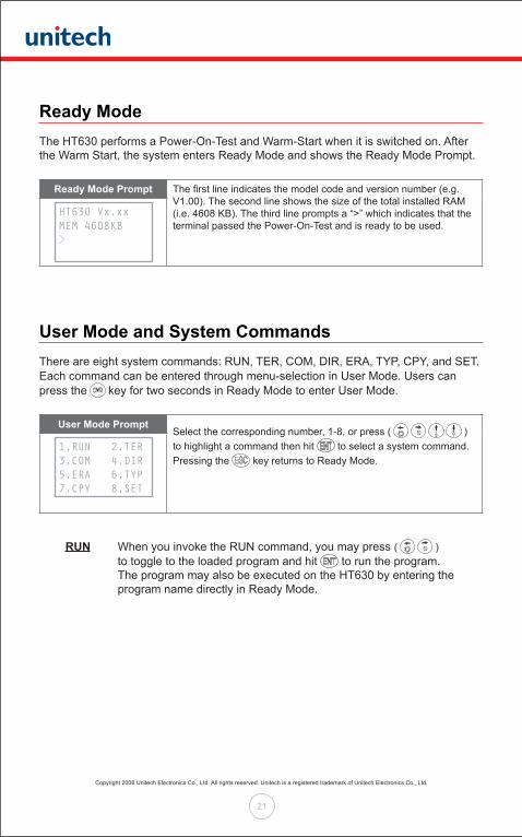
Ready ModeThe HT630 performs a Power-On-Test and Warm-Start when it is switched on. After the Warm Start, the system enters Ready Mode and shows the Ready Mode Prompt.
Ready Mode Prompt The first line indicates the model code and version number (e.g. V1.00). The second line shows the size of the total installed RAM (i.e. 4608 KB). The third line prompts a “>” which indicates that the terminal passed the Power-On-Test and is ready to be used.
User Mode and System CommandsThere are eight system commands: RUN, TER, COM, DIR, ERA, TYP, CPY, and SET. Each command can be entered through menu-selection in User Mode. Users can press the key for two seconds in Ready Mode to enter User Mode.
User Mode PromptSelect the corresponding number, 1-8, or press ( ) to highlight a command then hit to select a system command. Pressing the key returns to Ready Mode.
RUN When you invoke the RUN command, you may press ( ) to toggle to the loaded program and hit to run the program. The program may also be executed on the HT630 by entering the program name directly in Ready Mode.
HT630 Vx.xxMEM 4608KB>
1.RUN 2.TER3.COM 4.DIR5.ERA 6.TYP7.CPY 8.SET
Copyright 2008 Unitech Electronics Co., Ltd. All rights reserved. Unitech is a registered trademark of Unitech Electronics Co., Ltd.
22
TER This command puts the HT630 in either Terminal Emulation Mode or FormCaching Application Mode depending on which function you select. See Chapter 4 ‘Built-in Application - FormCaching’ for details on how to configure and use FormCaching.
In Terminal Emulation Mode, the HT630 transmits data to or receives data from a host computer. In this mode, data input from the bar code reader or keypad is displayed on screen and output to the serial port. Data received from the serial port is displayed on the LCD screen. Communication parameters, such as baud rate, data bits, parity, stop bits and flow control, must be set to be compatible with the destination in order to send data properly.
COM This command puts the HT630 in Kermit Server Mode. The following are the available Kermit commands for the Host/PC:
Command Description
Send filename Send a file from the Host/PC to the HT630 and store it in RAM
Get filename Get a file from the HT630 to the Host/PC
Remote dir List files stored in the HT630’s RAM
Remote Del filename Delete a data file stored in the HT630’s RAM
Make sure to set the HT630 communication parameters to match the Host/PC system before proceeding with data communication. Press to return to Ready Mode.
DIR This command shows the files stored in the HT630’s RAM with the following information:
• The list of file names stored in RAM • The size of the program execution area • The amount of free RAM left
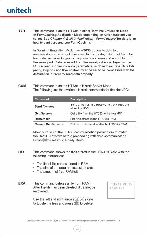
ERA This command deletes a file from RAM. After the file has been deleted, it cannot be recovered.
Use the left and right arrow ( ) keys to toggle the files and press to delete.
<ERASE FILE> SCAN.EXE
Copyright 2008 Unitech Electronics Co., Ltd. All rights reserved. Unitech is a registered trademark of Unitech Electronics Co., Ltd.
23
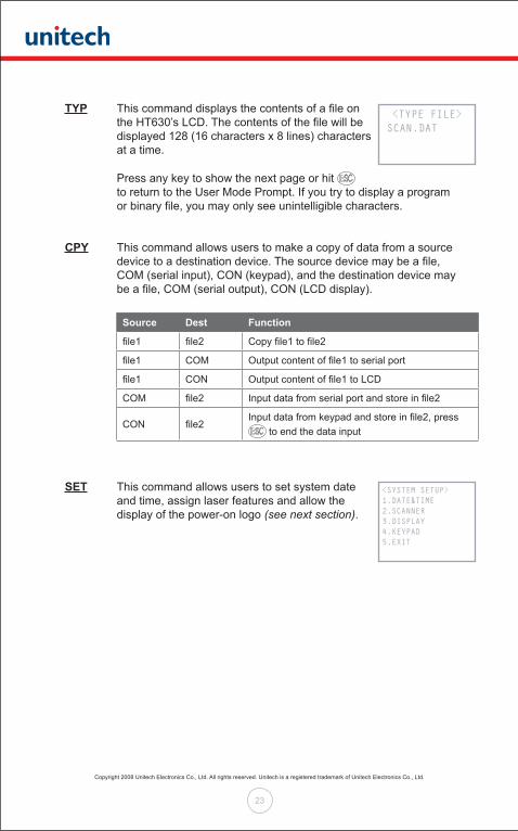
TYP This command displays the contents of a file on the HT630’s LCD. The contents of the file will be displayed 128 (16 characters x 8 lines) characters at a time.
Press any key to show the next page or hit to return to the User Mode Prompt. If you try to display a program or binary file, you may only see unintelligible characters.
CPY This command allows users to make a copy of data from a source device to a destination device. The source device may be a file, COM (serial input), CON (keypad), and the destination device may be a file, COM (serial output), CON (LCD display).
Source Dest Function
file1 file2 Copy file1 to file2
file1 COM Output content of file1 to serial port
file1 CON Output content of file1 to LCD
COM file2 Input data from serial port and store in file2
CON file2Input data from keypad and store in file2, press
to end the data input
SET This command allows users to set system date and time, assign laser features and allow the display of the power-on logo (see next section).
<TYPE FILE> SCAN.DAT
<SYSTEM SETUP>1.DATE&TIME2.SCANNER3.DISPLAY4.KEYPAD5.EXIT
Copyright 2008 Unitech Electronics Co., Ltd. All rights reserved. Unitech is a registered trademark of Unitech Electronics Co., Ltd.
24
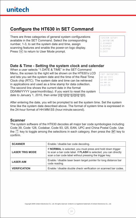
Configure the HT630 in SET CommandThere are three categories of general system configurationsavailable in the SET Command. Select the correspondingnumber, 1-3, to set the system date and time, assignscanning features and enable the power-on logo display.Press to return to User Mode prompt.
Date & Time - Setting the system clock and calendarWhen a user selects “1.DATE & TIME” in the SET Command Menu, the screen to the right will be shown on the HT630’s LCD and lets you set the system date and the time of the Real Time Clock chip (RTC). The system date and time can be retrieved in applications and used as a time stamp for data collection. The second line shows the current date in the format DD/MM/YYYY (year/month/day). If you want to reset the system date to January 1, 2010, then enter [0][1][0][1][2][0][1][0].
After entering the date, you will be prompted to set the system time. Set the system time like the system date described above. The format of system time is expressed in the 24-hour format of HH:MM:SS (hour:minute:second).
ScannerThe system software of the HT630 decodes all major bar code symbologies including Code 39, Code 128, Codabar, Code 93, I25, EAN, UPC and China Postal Code. Use the key to toggle among the selections in each category, then press the key to confirm.
SCANNER Enable / disable bar code decoding.
LASER TRIG MODEIf NORMAL is selected, you must press and hold down trigger to scan a bar code label. If FLASH is selected, you can directly scan a bar code label without pressing the trigger key.
LASER AIM Enable / disable laser beam target pointer for long distance bar code reading.
VERIFICATION Enable / disable double check verification on scanned bar codes.
<SYSTEM SETUP>1.DATE&TIME2.SCANNER3.DISPLAY4.KEYPAD5.EXIT
<SET DATE&TIME>mm-dd-yyyy12-03-2009hh-mm-ss14:07:50
Copyright 2008 Unitech Electronics Co., Ltd. All rights reserved. Unitech is a registered trademark of Unitech Electronics Co., Ltd.
25
DISPLAYEnable/disable the power-on logo display when the terminal is powered on.
KEYPADAllows users to set UPPER / LOWER case of each character.
EXITLeave the SET (setting) environment.

Copyright 2008 Unitech Electronics Co., Ltd. All rights reserved. Unitech is a registered trademark of Unitech Electronics Co., Ltd.
26
Uploading and Downloading Files
ESC CommandUploading or downloading by the Kermit server (see ‘User Mode and System Commands’ in Chapter 3 of this manual) requires the HT630 to be set to Kermit Server Mode by selecting user command “3.COM” in User Mode or by calling a system function in an application program.
The hardware and software on the HT630 is designed so the unit can be turned on upon receiving input from the serial port. The HT630 can also be instructed to process data communication by remote ESC commands through built-in MULTI communication protocol.
After linking the HT630 to a PC/Host, a communication program running on the host will send a few dummy bytes to the HT630 and delay for a few seconds to remotely turn on the unit. The program can send out data from a remote ESC command that matches the MULTI protocol to the HT630 and instruct the unit to perform certain processes.
For example, the HT630 will automatically execute the system routine to upload a file after receiving the valid “File upload” ESC command. Meanwhile, the program running on the host should follow the control flow of MULTI protocol and processes to receive the data.
For a detailed description of each ESC command and protocol, please see the HT630 Programming Reference Manual.
PTComm ManagerData may also be transferred to and from the HT630 with PTComm Manager whichcan be found on the Product CD in the HT630 packaging. PTComm Manager must be installed on the PC in order to communicate with the HT630. Once PTComm Manager is installed follow, these steps to transfer the data file to the PC:
1. Connect the HT630 to the Host/PC via the communication cable or cradle.
2. Open PTComm Manager.
3. Click on the HT630 icon under “File” or click on “Transfers” > “Connect Portable”
4. Verify the MODEL, ADDRESS, and COM PORT. Most importantly, to ensure a successful connection, select BOTH “Auto Detect Baud Rate” and “Auto Detect or Confirm Portable Model” and press OK.
Copyright 2008 Unitech Electronics Co., Ltd. All rights reserved. Unitech is a registered trademark of Unitech Electronics Co., Ltd.
27
5. The HT630 should BEEP even if it is OFF, PTComm Manager will automatically turn on the device and connect to it. If there is data in the device, it will be displayed under the Portable Name. Click and drag the “FORM.dat” file to a folder within the PC directory (left hand side of the screen).
uTransferThe uTransfer application is another option for communicating between a Host/PC and the HT630. uTransfer may be found on the Product CD in the HT630 packaging, or downloaded from the HT630 Product Page on the Unitech website. uTransfer must be installed on the PC in order to communicate with the HT630. Once uTransfer is installed, follow these steps to transfer the data file to the PC:
1. Connect the HT630 to the Host/PC via the communication cable or cradle.
2. Open uTransfer on your PC. Click the “Transfer” button in the uTransfer window to instantly transfer the data. It will search for a COM port from 1 to 20. (The files you wish to transfer from the HT630 must be in the default FORM.DAT format to successfully transfer to the Host/PC)
3. Make sure the HT630 is set to a COM port less than or equal to 20 in the Device Manager. To get to your Device Manager, go to the PC’s Control Panel, select “System” > “Hardware” > “Device Manager”. The COM port will be listed.
4. When uTransfer finishes searching all 20 COM ports, a message will display below the Transfer button showing you how many files have downloaded to your PC. If you have the “Sync Date and Time” option selected, the device will sync the day and time of the file with the PC.
If you wish to delete the data file on the device after it has been transferred to the PC, select the “Auto Delete Data” option before clicking Transfer.
5. By default, the file will be downloaded to your desktop with the file name FORM.DAT. If you have more than one device connected to the computer when you click Transfer, the second file will be named FORM02.DAT, and the third file will be FORM03.DAT, etc.
6. You may change the location of the file, as well as the file name and its extension in the Settings window. Click “Apply” or “OK” to save the changes.
Copyright 2008 Unitech Electronics Co., Ltd. All rights reserved. Unitech is a registered trademark of Unitech Electronics Co., Ltd.
28
Chapter 4
Built-in Application - FormCaching
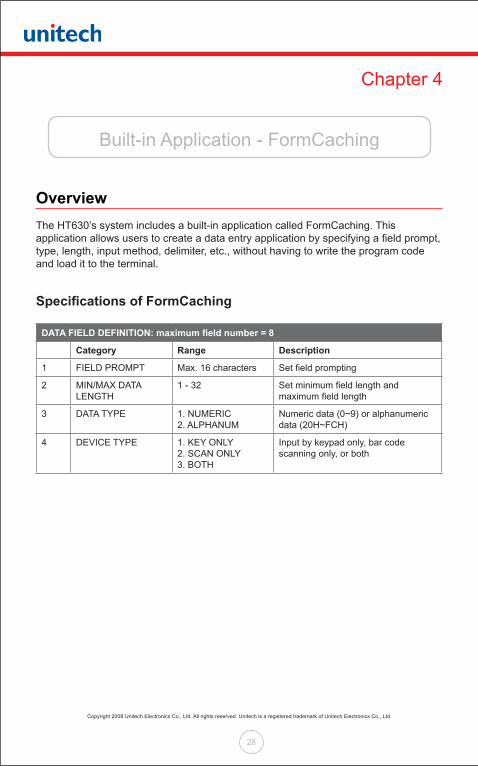
Overview The HT630’s system includes a built-in application called FormCaching. This application allows users to create a data entry application by specifying a field prompt, type, length, input method, delimiter, etc., without having to write the program code and load it to the terminal.
Specifications of FormCaching
DATA FIELD DEFINITION: maximum field number = 8
Category Range Description
1 FIELD PROMPT Max. 16 characters Set field prompting
2 MIN/MAX DATA LENGTH
1 - 32 Set minimum field length and maximum field length
3 DATA TYPE 1. NUMERIC2. ALPHANUM
Numeric data (0~9) or alphanumeric data (20H~FCH)
4 DEVICE TYPE 1. KEY ONLY2. SCAN ONLY3. BOTH
Input by keypad only, bar code scanning only, or both
Copyright 2008 Unitech Electronics Co., Ltd. All rights reserved. Unitech is a registered trademark of Unitech Electronics Co., Ltd.
29
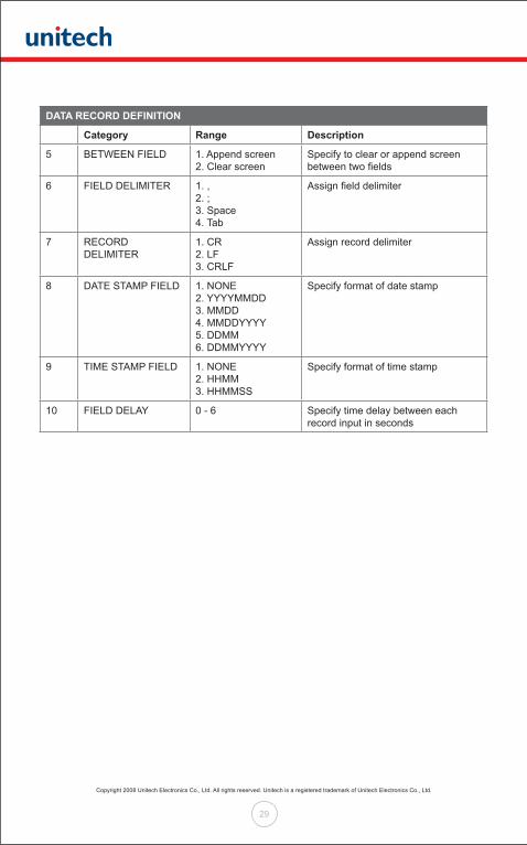
DATA RECORD DEFINITION
Category Range Description
5 BETWEEN FIELD 1. Append screen2. Clear screen
Specify to clear or append screen between two fields
6 FIELD DELIMITER 1. ,2. ;3. Space4. Tab
Assign field delimiter
7 RECORD DELIMITER
1. CR2. LF3. CRLF
Assign record delimiter
8 DATE STAMP FIELD 1. NONE2. YYYYMMDD 3. MMDD4. MMDDYYYY 5. DDMM6. DDMMYYYY
Specify format of date stamp
9 TIME STAMP FIELD 1. NONE2. HHMM3. HHMMSS
Specify format of time stamp
10 FIELD DELAY 0 - 6 Specify time delay between each record input in seconds

Copyright 2008 Unitech Electronics Co., Ltd. All rights reserved. Unitech is a registered trademark of Unitech Electronics Co., Ltd.
30
How to Create a FormCaching You will need to enter Supervisor Mode (see ‘Overview’ in Chapter 3 of this manual) and select the “4.FORM” category in order to set the configuration of FormCaching.
After selecting the “4.FORM” in Supervisor Mode, (the screen should match the diagram to the right), the system will ask you to specify four categories of the field specifications (field prompt, data length, data type and device type) of each data field.
This step also determines the number of fields in each record. After defining all data fields, press to end the setup of field specification. Or, you may also continue to set the last six categories including between field, field delimiter, record delimiter, date stamp field, time stamp field and field delay. When the FormCaching application is executed, a data file named FORM.DAT will be created to store the data. The system will not allow the user to redefine FormCaching if a FORM.DAT file currently exists. It is necessary to delete the FORM.DAT file in order to change the configuration of FormCaching.
How to Run FormCaching When FormCaching is enabled, the built-in application can be started by selecting the “2.TER” command in User Mode and then selecting “2.FORMCACHING”. The FormCaching application will run and follow the defined settings.
All scanned and keypad input data is saved to the file named FORM.DAT. You may use the key to browse a previous data record, press to step to the next record, and press to clear the record and then input a new value for every field of this record. Press to end FormCaching and return to System Ready Mode.
After collecting data, the FORM.DAT file can be uploaded to the PC/Host either through PTComm Manager, uTransfer, the Kermit server in User Mode, or through a remote ESC command.
FORMCACHING1:YES2:NOOTHER:EXIT
Copyright 2008 Unitech Electronics Co., Ltd. All rights reserved. Unitech is a registered trademark of Unitech Electronics Co., Ltd.
31
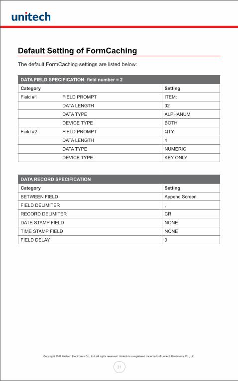
Default Setting of FormCaching The default FormCaching settings are listed below:
DATA FIELD SPECIFICATION: field number = 2
Category Setting
Field #1 FIELD PROMPT ITEM:
DATA LENGTH 32
DATA TYPE ALPHANUM
DEVICE TYPE BOTH
Field #2 FIELD PROMPT QTY:
DATA LENGTH 4
DATA TYPE NUMERIC
DEVICE TYPE KEY ONLY
DATA RECORD SPECIFICATION
Category Setting
BETWEEN FIELD Append Screen
FIELD DELIMITER ,
RECORD DELIMITER CR
DATE STAMP FIELD NONE
TIME STAMP FIELD NONE
FIELD DELAY 0

Copyright 2008 Unitech Electronics Co., Ltd. All rights reserved. Unitech is a registered trademark of Unitech Electronics Co., Ltd.
32
Chapter 5
Warranty
WarrantyThis mobile computer is warranted by Unitech to be free of defects in parts and workmanship for a period of one year from date of shipment. This warranty does not apply to defects resulting from action of the user such as misuse, improper wiring, operation outside of specification, improper maintenance or repair or unauthorized modification. Unitech specifically disclaims any implied warranties of merchantability or fitness for a specific purpose and will not be liable for any direct, indirect, special, incidental or consequential damages. Unitech’s total liability is limited to the repair or replacement of the product. The warranty set forth above is inclusive and no other warranty, whether written or oral is expressed or implied.
Warranty and/or Repair ServiceA Return Merchandise Authorization number must be issued before a unit is returned to Unitech for repair. Once a unit has been properly returned to Unitech (Note: The customer is responsible for ensuring proper packing to prevent damage in transit as well as the shipping costs back to Unitech), it will be repaired (estimates are provided first if the repair cost is estimated above $100.00) and returned via FedEx ground. The customer may elect a faster mode of transport at their cost.