Embed Size (px)
Citation preview
IMPORTANT NOTES:
1) This manual is valid for the following Model and associated serial numbers:
MODEL SERIAL NO. REV. NO.
2) A Change Page may be included at the end of the manual. All applicable changes andrevision number changes are documented with reference to the equipment serial num-bers. Before using this Instruction Manual, check your equipment serial number to identifyyour model. If in doubt, contact your nearest Kepco Representative, or the Kepco Docu-mentation Office in New York, (718) 461-7000, requesting the correct revision for yourparticular model and serial number.
3) The contents of this manual are protected by copyright. Reproduction of any part can be
made only with the specific written permission of Kepco, Inc. Data subject to change without notice.
KEPCO® THE POWER SUPPLIER™
MODEL
OPERATOR’S MANUAL
KEPCO INC.
ORDER NO. REV. NO.
KEPCO, INC. 131-38 SANFORD AVENUE FLUSHING, NY. 11355 U.S.A. TEL (718) 461-7000 FAX (718) 767-1102email: [email protected] World Wide Web: http://www.kepcopower.com
An ISO 9001 Company.
©2010, KEPCO, INCP/N 243-0851-b
HSP SERIES
1000 AND 1500 WATT SWITCHING POWER SUPPLY
VOLTAGE/CURRENT STABILIZED DC SOURCE
HSP SERIES POWER SUPPLY

HSP OPR 090910 i/(ii Blank)
TABLE OF CONTENTS
SECTION PAGE
SECTION 1 - INTRODUCTION1.1 Scope of Manual ..................................................................................................................................... 1-11.2 General Description................................................................................................................................. 1-11.3 Specifications .......................................................................................................................................... 1-11.4 Miscellaneous Features .......................................................................................................................... 1-51.4.1 Control/Programming......................................................................................................................... 1-51.4.2 Status Indicators/Flags ...................................................................................................................... 1-51.4.3 Setpoint Monitors:.............................................................................................................................. 1-51.4.4 Remote Error Sensing: ...................................................................................................................... 1-51.4.5 Load Sharing: .................................................................................................................................... 1-51.4.6 Load Monitor:..................................................................................................................................... 1-61.4.7 Auxiliary Supply: ................................................................................................................................ 1-61.4.8 Overcurrent/Undervoltage Protection: ............................................................................................... 1-61.4.9 Current Walk-in:................................................................................................................................. 1-61.4.10 Remote Reset:................................................................................................................................... 1-61.5 Options .................................................................................................................................................... 1-61.5.1 Meters (M Suffix): .............................................................................................................................. 1-61.5.2 Battery Chargers (B Suffix):............................................................................................................... 1-61.5.3 Internal Blocking Diode (R Suffix):..................................................................................................... 1-61.6 Accessories ............................................................................................................................................. 1-6
SECTION 2 - INSTALLATION2.1 Unpacking and Inspection ....................................................................................................................... 2-12.2 Terminations and Controls ...................................................................................................................... 2-12.3 Source Power Requirements .................................................................................................................. 2-32.4 Cooling .................................................................................................................................................... 2-32.5 Preliminary Operational Check................................................................................................................ 2-32.6 Installation ............................................................................................................................................... 2-42.7 Wiring Instructions................................................................................................................................... 2-42.7.1 Safety Grounding............................................................................................................................... 2-42.7.2 Source Power Connections ............................................................................................................... 2-52.7.3 D-C Output Grounding....................................................................................................................... 2-52.7.4 Power Supply/Load Interface............................................................................................................. 2-62.7.5 Load Connection - General................................................................................................................ 2-62.7.5.1 Load Connection - Method I (Local Error Sensing)...................................................................... 2-72.7.5.2 Load Connection - Method II (Remote Error Sensing)................................................................. 2-82.7.5.3 Load Connection - Method III (Series Connection)...................................................................... 2-92.7.5.4 Load Connection - Method IV (Parallel Operation) ...................................................................... 2-102.7.5.4.1 Redundancy and Hot Swap Applications ................................................................................2-102.7.6 Load Sharing ..................................................................................................................................... 2-112.7.7 Signal Connections............................................................................................................................ 2-122.8 Mechanical Keying .................................................................................................................................. 2-122.9 Retaining Latches.................................................................................................................................... 2-12
SECTION 3 - OPERATING INSTRUCTIONS3.1 Operating Configuration .......................................................................................................................... 3-13.2 Remote Error Sense................................................................................................................................ 3-13.3 Output Voltage Programming.................................................................................................................. 3-13.4 Output Voltage Range............................................................................................................................. 3-23.5 Current Limit Programming ..................................................................................................................... 3-23.6 Current Limit Programming Range.......................................................................................................... 3-33.7 Setpoint Monitors .................................................................................................................................... 3-33.8 Overvoltage Protection Adjustment ......................................................................................................... 3-43.9 Current Limit Characteristic ..................................................................................................................... 3-53.10 Current Walk-in Circuit ............................................................................................................................ 3-63.11 5VAUX Floating Supply........................................................................................................................... 3-63.12 Remote Inhibit/Remote Reset Controls ................................................................................................... 3-7
HSP OPR 090910 iii
TABLE OF CONTENTS
SECTION PAGE
LIST OF FIGURES
FIGURE PAGE
LIST OF TABLES
TABLE PAGE
3.13 Module Current Monitor........................................................................................................................... 3-73.14 Status Indicators and Status Flags.......................................................................................................... 3-83.14.1 Power Indicator/Source Power Status Flags ..................................................................................... 3-93.14.2 DCFAIL Indicator and Output Status Flags ....................................................................................... 3-103.14.3 OVERTEMP Indicator and Status Flags............................................................................................ 3-103.14.4 FANFAIL Indicator and Status Flags ................................................................................................. 3-103.15 Front Panel Meter (M Option) Operation................................................................................................. 3-103.15.1 Voltmeter Operation........................................................................................................................... 3-113.15.2 Ammeter Operation ........................................................................................................................... 3-113.15.3 Parallel/redundant Operation............................................................................................................. 3-113.16 Battery (B Option) Operation................................................................................................................... 3-12
1-1 HSP Series Power Supply ............................................................................................................................ iv1-2 HSP (All), Nominal Mains Voltage: Temperature Derating, ........................................................................ 1-31-3 HSP 1500W, Low Mains Voltage: Temperature, Power Derating............................................................... 1-31-4 Outline Drawing .......................................................................................................................................... 1-42-1 HSP Series Front Panel Controls and Indicators ........................................................................................ 2-12-2 Configuration Switch Functions .................................................................................................................. 2-12-3 HSP Series Rear Panel Connections ......................................................................................................... 2-22-4 Load Connection - Method I (Local Error Sensing)..................................................................................... 2-72-5 Load Connection - Method II (Remote Error Sensing)................................................................................ 2-82-6 Load Connection - Method III - (Series Connection)................................................................................... 2-92-7 Load Connection - Method IV (Parallel/Redundant Operation with Hot-Swap) .......................................... 2-103-1 External Resistance Programming of Output Voltage................................................................................. 3-23-2 External Voltage Programming of Output Voltage ...................................................................................... 3-23-3 External Voltage Programming of Current Limit.......................................................................................... 3-33-4 Current Walk-in Characteristic .................................................................................................................... 3-63-5 Remote Inhibit Control Operation ............................................................................................................... 3-73-6 Timing Diagram for POWER and DCFAIL Status....................................................................................... 3-93-7 HSP M (Meter) Option and B (Battery Charger) Option, Front Panel ......................................................... 3-12
1-1 Model Parameters .......................................................................................................................................1-11-2 General Specifications ................................................................................................................................1-21-3 Accessories .................................................................................................................................................1-72-1 Configuration Controls ................................................................................................................................2-12-1 I/O Connector Pin Assignments ..................................................................................................................2-23-1 Status Indicators and Flags ........................................................................................................................3-83-2 Fault Detector Operation .............................................................................................................................3-103-3 B Option Fault Detection Window ...............................................................................................................3-12

iv HSPSERIES 090910
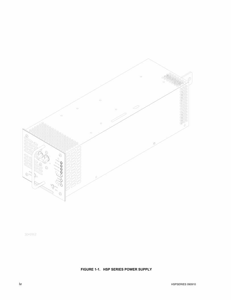
FIGURE 1-1. HSP SERIES POWER SUPPLY
HSPSERIES OPR 090910 1-1
SECTION 1 - INTRODUCTION
1.1 SCOPE OF MANUAL
This manual contains instructions for the installation and operation of the HSP series of voltageand current stabilized d-c power supplies manufactured by Kepco, Inc., Flushing, New York,U.S.A.
1.2 GENERAL DESCRIPTION
The HSP power supply (Figure 1-1) is basically a voltage and current stabilized d-c source witha relatively sharp crossover between voltage and current mode operation. This permits HSPs tobe used both as conventional regulated voltage sources and in applications such as batterychargers, where automatic crossover between constant voltage and constant current operationis required.
HSP power supplies are supplied in a single mechanical size and are nominally rated at either1000 or 1500 watts of output power. HSP 1000 watt power supplies are designed to operateover the universal a-c power mains voltage range of 90-277V (47-63Hz), with operation from125-420V d-c also available. HSP 1500 watt products provide full power over the a-c mainsrange of range of 180-277V a-c, and 1000W output power from 90-132V a-c; contact Kepco forinformation on operation over other source voltage ranges. Active power factor correction cir-cuitry limits source current harmonics to negligible levels, significantly improving source powerutilization. Cooling is provided via an internal d-c fan.
The HSP permits adjustment of both output voltage (VO) and current limit (IMAX), either by inter-nal (front panel pot) or external (resistance or voltage) methods; programming method isselected via DIP switches accessed through the top of the unit. Independent circuitry providesprotection against overvoltage, overcurrent and overtemperature failures; fault detection cir-cuitry monitors performance of the output and critical internal functions, providing both visualand electrical indicators. A switch-selectable “current walk-in” circuit and optional float/equalizefunctions enhance the performance of HSP power supplies for such applications as batterychargers.
The HSP power supply is specifically designed for both fixed installation operation and, whenused in conjunction with Kepco RA 60 or similar plug-in rack adapters, as a hot replaceablemodule in a redundant power system. Forced current sharing and optional internal or externaloutput blocking diodes enhance power system reliability. Mechanical keying eliminates the riskof incorrect module insertion. Tool-operated latches on the front panel provide positive securityagainst casual removal of an operating module.
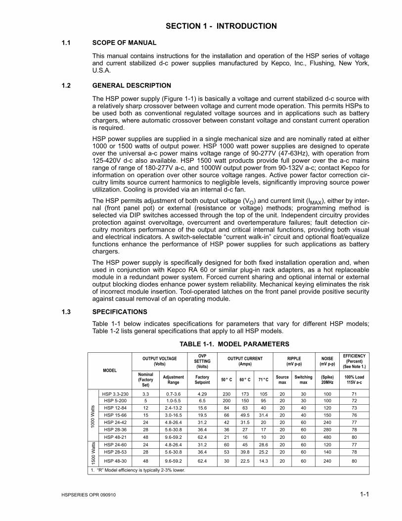
1.3 SPECIFICATIONS
Table 1-1 below indicates specifications for parameters that vary for different HSP models;Table 1-2 lists general specifications that apply to all HSP models.
TABLE 1-1. MODEL PARAMETERS
MODEL
OUTPUT VOLTAGE(Volts)
OVPSETTING
(Volts)OUTPUT CURRENT
(Amps)RIPPLE(mV p-p)
NOISE(mV p-p)
EFFICIENCY(Percent)
(See Note 1.)Nominal (Factory
Set)Adjustment
RangeFactorySetpoint 50 ° C 60 ° C 71 ° C Source
maxSwitching
max(Spike)20MHz
100% Load115V a-c
HSP 3.3-230 3.3 0.7-3.6 4.29 230 173 105 20 30 100 71HSP 5-200 5 1.0-5.5 6.5 200 150 95 20 30 100 72HSP 12-84 12 2.4-13.2 15.6 84 63 40 20 40 120 73HSP 15-66 15 3.0-16.5 19.5 66 49.5 31.4 20 40 150 76HSP 24-42 24 4.8-26.4 31.2 42 31.5 20 20 60 240 77HSP 28-36 28 5.6-30.8 36.4 36 27 17 20 60 280 78HSP 48-21 48 9.6-59.2 62.4 21 16 10 20 60 480 80HSP 24-60 24 4.8-26.4 31.2 60 45 28.6 20 60 120 77HSP 28-53 28 5.6-30.8 36.4 53 39.8 25.2 20 60 140 78
HSP 48-30 48 9.6-59.2 62.4 30 22.5 14.3 20 60 240 80
1. “R” Model efficiency is typically 2-3% lower.
1000
Wat
ts15
00 W
atts
FIGURE 0-1.
1-2 HSPSERIES OPR 090910
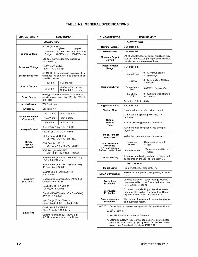
TABLE 1-2. GENERAL SPECIFICATIONS
CHARACTERISTIC REQUIREMENT
SOURCE INPUT
Source Voltage
AC: Single-Phase, 1000W 1500W
Nominal: 100-250V rms 200-250V rmsRange: 90-277Vrms 180-277V rms
DC: 125-420V d-c (polarity insensitive)(See Note 1.)
Brownout Voltage 1000W:75 V a-c typ.1500W:150 V a-c typ.
Source Frequency47-440 Hz (Frequencies in excess of 63Hz will cause leakage current to exceed limits specified below)
Source Current120V a-c 11A rms max
240V a-c 1000W: 5.5A rms max1500W: 8.0A rms max
Power Factor0.99 typical; 0.96 minimum for all source conditions and loads from 25% to 100% of rated load.
Inrush Current 75A Peak max
Efficiency See Table 1-1.
Withstand Voltage(See Note 2)
3000V rms Input to Output
1500V rms Input to Case
500V d-c Output to Case
Leakage Current<0.50mA @ 115V a-c, 47-63Hz
<1.0mA @ 230V a-c, 47-63Hz
SafetyAgency
Approvals
UL Recognized (SELV)UL 1950 / UL1459 Para. 35A.1
CSA Certified (SELV)CSA 22.2 No. 234-M90 (Level 5)
VDE Recognized (SELV)VDE 0805 / EN 60950 / IEC 950
Immunity(See Note 3)
Radiated RF (Ampl. Mod.) (ENV50140)10V/m, 80-1000MHz
Radiated RF (Pulse Mod.) (ENV50204)(Pulse) 10V/m, 900MHz
Magnetic Field (EN 61000-4-8)30A/m, 50Hz
Electrostatic Discharge (EN 61000-4-2)Contact: 4KV, Air: 8KV
Conducted RF (ENV50141)10Vrms, 0.15-80MHz
Electrical Fast Transient (EN 61000-4-4)2KV, Tr/Th = 8/20µs
Input Surge (EN 61000-4-5)Comm. Mode: 2KV; Diff. Mode: 2KV
Emissions
Conducted RF (CISPR 22)Class A Limits, 0.15-30MHz
Current Harmonics (EN 61000-3-2)0-2KHz, any source/load condition)
CHARACTERISTIC REQUIREMENT
OUTPUT/LOAD
Nominal Voltage See Table 1-1.
Rated Current See Table 1-1.
Minimum OutputCurrent
2% of rated load (lower output conditions may result in increased output ripple and increased transient response recovery time).
Output Voltage Range See Table 1-1.
Regulation Error
Source Effect 0.1% over full source voltage range
Load Effect 0.1% from 5% to 100% of rated load
Temperature Effect 0.02%/oC, 0oC<TA<50oC
Time Effect (Drift)
0.1%/24 hr period after 30 min. warm-up
Combined Effect 0.3%
Ripple and Noise See Table 1-1.
Start-up Time 1 sec maximum at rated output current
OutputHold-up
Time
21.5 msec transparent power loss (no indication)
5 msec following power loss indication
>27 msec total time prior to loss of output regulation
Turn-on/Turn-offOvershoot Within load transient response envelope
Load Transient Response
(25% load transient, 2A/µsec rise/fall time)
Maximum excursion
3% of nominal output voltage
Recovery time 100µsec return to within 1% of set voltage
Output Polarity All outputs are floating and can be referenced as required by the user at up to ±500V d-c.
PROTECTION
Input Fusing Front Panel circuit breaker (2-line)
Low A-C Protection HSP Power supplies will self-protect, no fixed limit.
OvervoltageProtection
Latched shutdown if output voltage exceeds user-selected limit (see Operating Instructions, PAR. 3.8) (see Note 4).
OvercurrentProtection
Constant current limiting (optional undervol-tage-activated latched shutdown (see Operat-ing Instructions, PAR. 3.9) (see Note 4).
Overtemperature Protection
Thermostat shutdown with hysteretic recovery and automatic restart.
NOTES:1. Safety Agency approval not applicable for noted conditions.
2. 25o C, 65% RH
3. Per EN 50082-2, Acceptance Criteria A
4. Latched shutdown requires that source power be cycled for restart (optional restart by cycling REMOTE ON/OFF control signal); see Operating Instructions, PAR. 3.12.
HSPSERIES OPR 090910 1-3
TABLE 1-2. GENERAL SPECIFICATIONS (Continued)
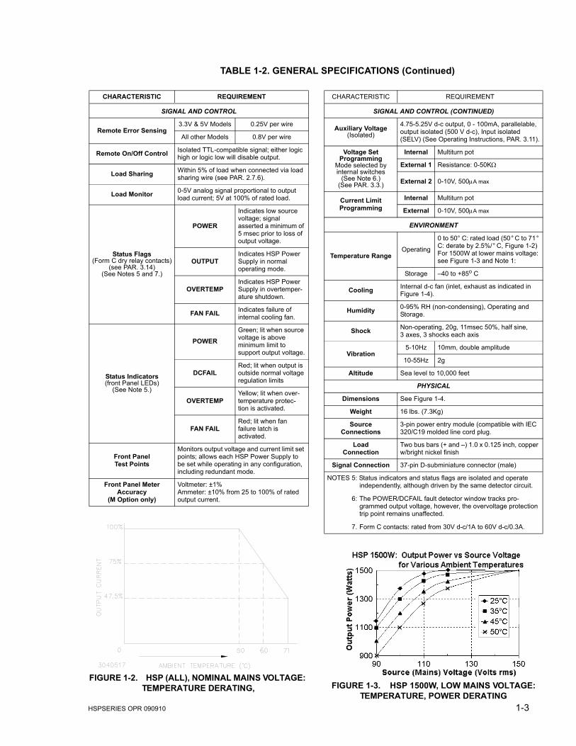
FIGURE 1-2. HSP (ALL), NOMINAL MAINS VOLTAGE: TEMPERATURE DERATING, FIGURE 1-3. HSP 1500W, LOW MAINS VOLTAGE:
TEMPERATURE, POWER DERATING
CHARACTERISTIC REQUIREMENT
SIGNAL AND CONTROL
Remote Error Sensing3.3V & 5V Models 0.25V per wire
All other Models 0.8V per wire
Remote On/Off Control Isolated TTL-compatible signal; either logic high or logic low will disable output.
Load Sharing Within 5% of load when connected via load sharing wire (see PAR. 2.7.6).
Load Monitor 0-5V analog signal proportional to output load current; 5V at 100% of rated load.
Status Flags(Form C dry relay contacts)
(see PAR. 3.14)(See Notes 5 and 7.)
POWER
Indicates low source voltage; signal asserted a minimum of 5 msec prior to loss of output voltage.
OUTPUTIndicates HSP Power Supply in normal operating mode.
OVERTEMPIndicates HSP Power Supply in overtemper-ature shutdown.
FAN FAIL Indicates failure of internal cooling fan.
Status Indicators(front Panel LEDs)
(See Note 5.)
POWERGreen; lit when source voltage is above minimum limit to support output voltage.
DCFAILRed; lit when output is outside normal voltage regulation limits
OVERTEMPYellow; lit when over-temperature protec-tion is activated.
FAN FAILRed; lit when fan failure latch is activated.
Front PanelTest Points
Monitors output voltage and current limit set points; allows each HSP Power Supply to be set while operating in any configuration, including redundant mode.
Front Panel MeterAccuracy
(M Option only)
Voltmeter: ±1%Ammeter: ±10% from 25 to 100% of rated output current.
CHARACTERISTIC REQUIREMENT
SIGNAL AND CONTROL (CONTINUED)
Auxiliary Voltage(Isolated)
4.75-5.25V d-c output, 0 - 100mA, parallelable, output isolated (500 V d-c), Input isolated (SELV) (See Operating Instructions, PAR. 3.11).
Voltage SetProgramming
Mode selected byinternal switches
(See Note 6.)(See PAR. 3.3.)
Internal Multiturn pot
External 1 Resistance: 0-50KΩ
External 2 0-10V, 500µA max
Current LimitProgramming
Internal Multiturn pot
External 0-10V, 500µA max
ENVIRONMENT
Temperature RangeOperating
0 to 50° C: rated load (50° C to 71° C: derate by 2.5%/° C, Figure 1-2) For 1500W at lower mains voltage: see Figure 1-3 and Note 1:
Storage –40 to +85o C
Cooling Internal d-c fan (inlet, exhaust as indicated in Figure 1-4).
Humidity 0-95% RH (non-condensing), Operating and Storage.
Shock Non-operating, 20g, 11msec 50%, half sine, 3 axes, 3 shocks each axis
Vibration5-10Hz 10mm, double amplitude
10-55Hz 2g
Altitude Sea level to 10,000 feet
PHYSICAL
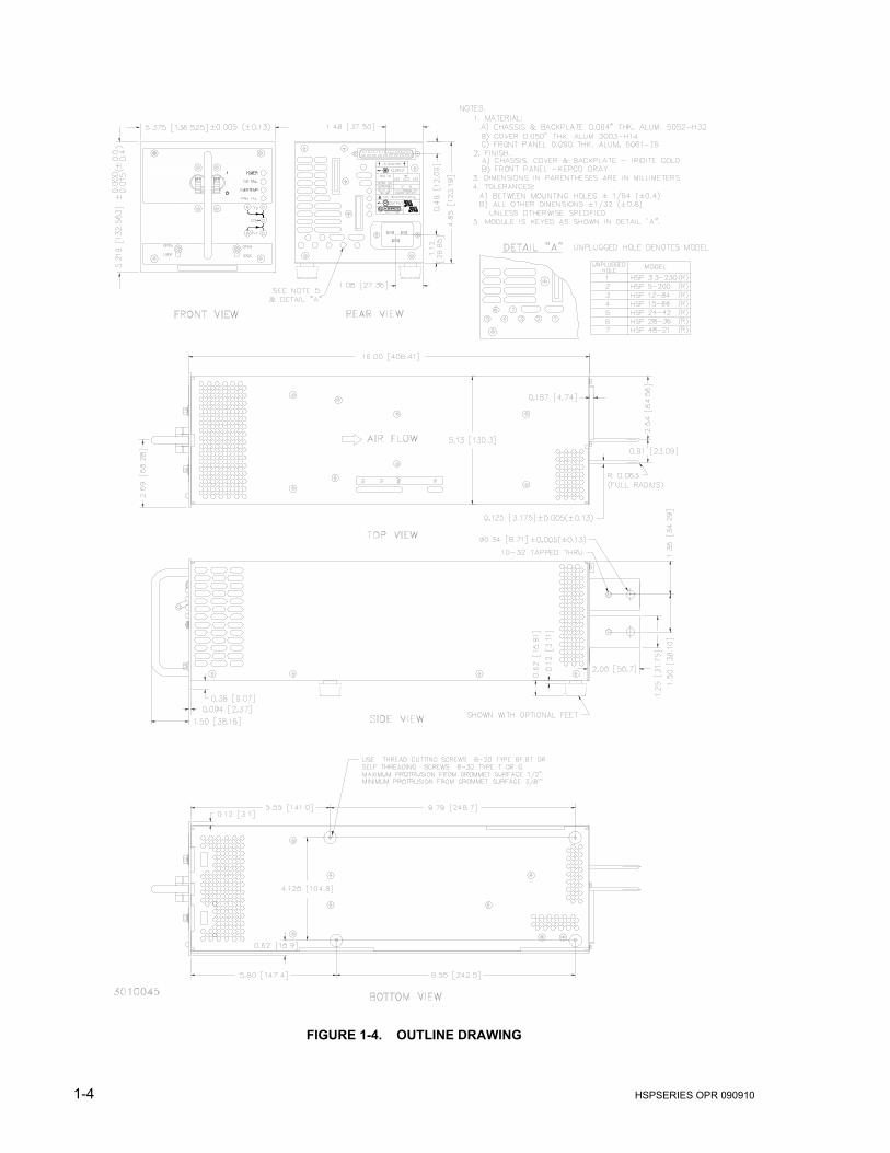
Dimensions See Figure 1-4.
Weight 16 lbs. (7.3Kg)
SourceConnections
3-pin power entry module (compatible with IEC 320/C19 molded line cord plug.
LoadConnection
Two bus bars (+ and –) 1.0 x 0.125 inch, copper w/bright nickel finish
Signal Connection 37-pin D-subminiature connector (male)
NOTES 5: Status indicators and status flags are isolated and operate independently, although driven by the same detector circuit.
6: The POWER/DCFAIL fault detector window tracks pro-grammed output voltage, however, the overvoltage protection trip point remains unaffected.
7. Form C contacts: rated from 30V d-c/1A to 60V d-c/0.3A.
1-4 HSPSERIES OPR 090910
FIGURE 1-4. OUTLINE DRAWING
HSPSERIES OPR 090910 1-5
1.4 MISCELLANEOUS FEATURES
1.4.1 CONTROL/PROGRAMMING
a) VOLTAGE CHANNEL: Output voltage is controlled continuously throughout the specifiedadjustment range via a 10-turn potentiometer mounted behind the front panel. Externalcontrol can be exercised either by resistance or by control voltage (see PAR’s. 3.3 and3.4).
b) CURRENT CHANNEL: Output current is controlled continuously throughout the specifiedadjustment range via a 10-turn potentiometer mounted behind the front panel. Externalcontrol can be exercised by control voltage (see PAR’s. 3.5 and 3.6).
c) OVERVOLTAGE LEVEL: The output voltage level at which the overvoltage protectionlatch is activated may be adjusted locally via a 10-turn potentiometer accessed through thetop cover (see PAR. 3.8).
d) REMOTE INHIBIT: Operation of the output regulator can be inhibited remotely via eitherone of two TTL-level control lines, RC1 and RC2. Both of these signals are isolated fromboth the input and output, allowing single-point control of several power supplies operatingat different potentials. Both positive and negative logic are supported (see PAR. 3.12).
1.4.2 STATUS INDICATORS/FLAGS
a) STATUS INDICATORS: Four LED indicators at the front panel provide the following opera-tional information (see PAR. 3.14):
• POWER: Green; lit when source voltage is above minimum required to support ratedload.
• DCFAIL: Red; lit when output voltage is beyond regulation limits or when load current isbelow minimum load sharing requirement.
• OVERTEMP: Amber; lit when internal overtemperature protection is activated.
• FANFAIL: Red; lit when internal cooling fan failure is detected.
b) STATUS FLAGS: Four sets of Form C dry relay contacts (3 wires each) are provided at theI/O connector which duplicate the front panel status indicator functions (see PAR. 3.14).
1.4.3 SETPOINT MONITORS: Analog voltage signals which display programmed output voltage andcurrent limit values. These signals are available both at the front panel test points (VO and IMAX)and at the I/O connector (VSET and ISET). Signals are referenced to negative error sense (seePAR. 3.7).
1.4.4 REMOTE ERROR SENSING: Separate voltage sensing connections permit 4-wire connectionto load. Will compensate for static load effects due to power lead d-c resistance (DCR) up tospecified maximum voltage drop per load lead at maximum specified output voltage (see PAR.3.2).
1.4.5 LOAD SHARING: Bidirectional control port provides forced load sharing between two or moreHSP (or HSM) series power supplies wired in parallel (see PAR. 2.7.6).
1-6 HSPSERIES OPR 090910
1.4.6 LOAD MONITOR: Analog voltage signal which indicates actual load current delivered by theHSP power supply (see PAR. 3.13).
1.4.7 AUXILIARY SUPPLY: Logic-level secondary output provides up to 0.5 watts of power at 5Vd-c. This output is isolated from the output and is unaffected by the status of the main output.Provides power for external Remote Inhibit controls (see PAR. 3.11).
1.4.8 OVERCURRENT/UNDERVOLTAGE PROTECTION: Switch-selectable option provides theuser load protection against long-term output overloads or undervoltage conditions (see PAR.3.9).
1.4.9 CURRENT WALK-IN: Switch-selectable option provides control of output current rise ratebased on Bellcore TR-TSY-000947 requirements for battery chargers (see PAR. 3.10).
1.4.10 REMOTE RESET: Switch-selectable option provides capability to reset the latch used by theovervoltage protection circuitry to disable the output regulator, using the Remote Inhibit controllines (see PAR. 3.12).
1.5 OPTIONS
HSP options are described below; more than one option may be incorporated into any HSPPower Supply.
1.5.1 METERS (M SUFFIX): HSP power supplies are available with an optional front panel meterwhich displays output voltage and output current (switch selectable). Refer to PAR. 3.15 foroperation.
1.5.2 BATTERY CHARGERS (B SUFFIX): The battery charger option adds switch selectable “float”and “equalize” functions which provide two separate voltage regulation settings, as well as anexpanded window for the output voltage fault detector compatible with normal battery operatingvoltages (Refer to PAR. 3.16 for operation).
1.5.3 INTERNAL BLOCKING DIODE (R SUFFIX): This option adds a blocking diode in series withthe output, required for “hot swap” applications.
1.6 ACCESSORIES
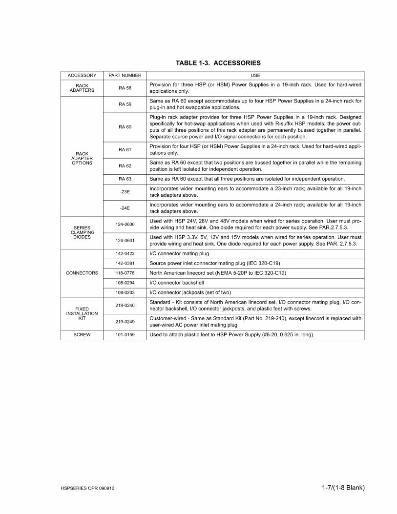
Accessories for HSP Power Supplies are listed in Table 1-3.
HSPSERIES OPR 090910 1-7/(1-8 Blank)
TABLE 1-3. ACCESSORIES
ACCESSORY PART NUMBER USE
RACKADAPTERS RA 58
Provision for three HSP (or HSM) Power Supplies in a 19-inch rack. Used for hard-wiredapplications only.
RACKADAPTER OPTIONS
RA 59Same as RA 60 except accommodates up to four HSP Power Supplies in a 24-inch rack forplug-in and hot swappable applications.
RA 60
Plug-in rack adapter provides for three HSP Power Supplies in a 19-inch rack. Designedspecifically for hot-swap applications when used with R-suffix HSP models; the power out-puts of all three positions of this rack adapter are permanently bussed together in parallel.Separate source power and I/O signal connections for each position.
RA 61Provision for four HSP (or HSM) Power Supplies in a 24-inch rack. Used for hard-wired appli-cations only.
RA 62Same as RA 60 except that two positions are bussed together in parallel while the remainingposition is left isolated for independent operation.
RA 63 Same as RA 60 except that all three positions are isolated for independent operation.
-23EIncorporates wider mounting ears to accommodate a 23-inch rack; available for all 19-inchrack adapters above.
-24EIncorporates wider mounting ears to accommodate a 24-inch rack; available for all 19-inchrack adapters above.
SERIES CLAMPING
DIODES
124-0600Used with HSP 24V, 28V and 48V models when wired for series operation. User must pro-vide wiring and heat sink. One diode required for each power supply. See PAR.2.7.5.3.
124-0601Used with HSP 3.3V, 5V, 12V and 15V models when wired for series operation. User mustprovide wiring and heat sink. One diode required for each power supply. See PAR. 2.7.5.3.
CONNECTORS
142-0422 I/O connector mating plug
142-0381 Source power inlet connector mating plug (IEC 320-C19)
118-0776 North American linecord set (NEMA 5-20P to IEC 320-C19)
108-0294 I/O connector backshell
108-0203 I/O connector jackposts (set of two)
FIXEDINSTALLATION
KIT
219-0240Standard - Kit consists of North American linecord set, I/O connector mating plug, I/O con-nector backshell, I/O connector jackposts, and plastic feet with screws.
219-0249Customer-wired - Same as Standard Kit (Part No. 219-240), except linecord is replaced withuser-wired AC power inlet mating plug.
SCREW 101-0159 Used to attach plastic feet to HSP Power Supply (#6-20, 0.625 in. long).

HSPSERIES OPR 090910 2-1
SECTION 2 - INSTALLATION
2.1 UNPACKING AND INSPECTION
This instrument has been thoroughly inspected and tested prior to packing and is ready foroperation. After careful unpacking, inspect for shipping damage before attempting to operate.Perform the preliminary operational check as outlined in PAR. 2.5. If any indication of damage isfound, file an immediate claim with the responsible transport service.
2.2 TERMINATIONS AND CONTROLS
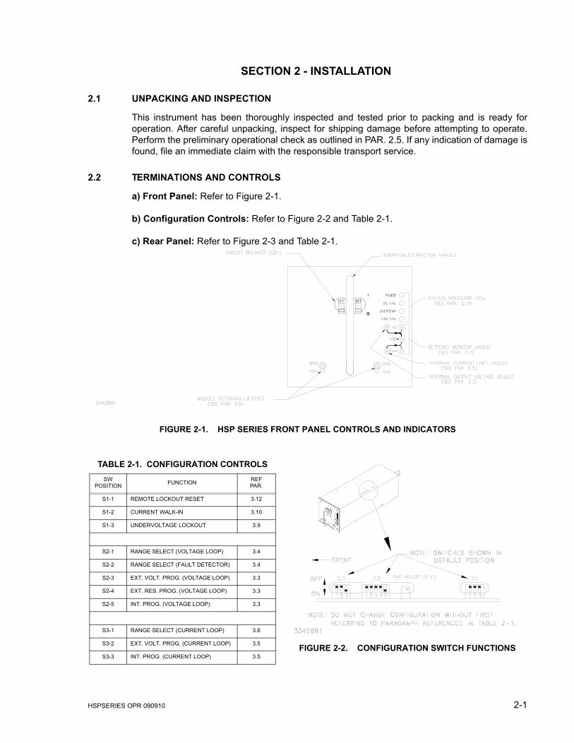
a) Front Panel: Refer to Figure 2-1.
b) Configuration Controls: Refer to Figure 2-2 and Table 2-1.
c) Rear Panel: Refer to Figure 2-3 and Table 2-1.
FIGURE 2-1. HSP SERIES FRONT PANEL CONTROLS AND INDICATORS
FIGURE 2-2. CONFIGURATION SWITCH FUNCTIONS
TABLE 2-1. CONFIGURATION CONTROLSSW
POSITION FUNCTION REFPAR.
S1-1 REMOTE LOCKOUT RESET 3.12
S1-2 CURRENT WALK-IN 3.10
S1-3 UNDERVOLTAGE LOCKOUT 3.9
S2-1 RANGE SELECT (VOLTAGE LOOP) 3.4
S2-2 RANGE SELECT (FAULT DETECTOR) 3.4
S2-3 EXT. VOLT. PROG. (VOLTAGE LOOP) 3.3
S2-4 EXT. RES. PROG. (VOLTAGE LOOP) 3.3
S2-5 INT. PROG. (VOLTAGE LOOP) 3.3
S3-1 RANGE SELECT (CURRENT LOOP) 3.6
S3-2 EXT. VOLT. PROG. (CURRENT LOOP) 3.5
S3-3 INT. PROG. (CURRENT LOOP) 3.5
2-2 HSPSERIES OPR 090910
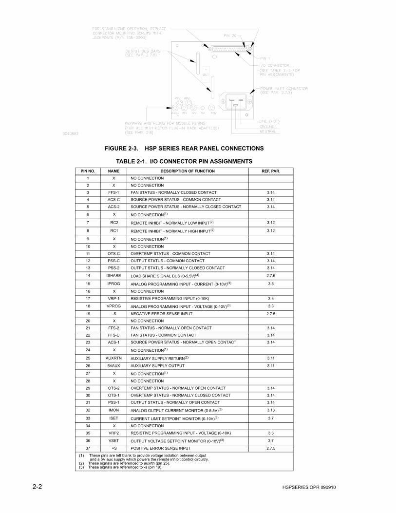
FIGURE 2-3. HSP SERIES REAR PANEL CONNECTIONS
TABLE 2-1. I/O CONNECTOR PIN ASSIGNMENTSPIN NO. NAME DESCRIPTION OF FUNCTION REF. PAR.
1 X NO CONNECTION
2 X NO CONNECTION
3 FFS-1 FAN STATUS - NORMALLY CLOSED CONTACT 3.14
4 ACS-C SOURCE POWER STATUS - COMMON CONTACT 3.14
5 ACS-2 SOURCE POWER STATUS - NORMALLY CLOSED CONTACT 3.14
6 X NO CONNECTION(1)
7 RC2 REMOTE INHIBIT - NORMALLY LOW INPUT(2) 3.12
8 RC1 REMOTE INHIBIT - NORMALLY HIGH INPUT(2) 3.12
9 X NO CONNECTION(1)
10 X NO CONNECTION
11 OTS-C OVERTEMP STATUS - COMMON CONTACT 3.14
12 PSS-C OUTPUT STATUS - COMMON CONTACT 3.14
13 PSS-2 OUTPUT STATUS - NORMALLY CLOSED CONTACT 3.14
14 ISHARE LOAD SHARE SIGNAL BUS (0-5.5V)(3) 2.7.6
15 IPROG ANALOG PROGRAMMING INPUT - CURRENT (0-10V)(3) 3.5
16 X NO CONNECTION
17 VRP-1 RESISTIVE PROGRAMMING INPUT (0-10K) 3.3
18 VPROG ANALOG PROGRAMMING INPUT - VOLTAGE (0-10V)(3) 3.3
19 -S NEGATIVE ERROR SENSE INPUT 2.7.5
20 X NO CONNECTION
21 FFS-2 FAN STATUS - NORMALLY OPEN CONTACT 3.14
22 FFS-C FAN STATUS - COMMON CONTACT 3.14
23 ACS-1 SOURCE POWER STATUS - NORMALLY OPEN CONTACT 3.14
24 X NO CONNECTION(1)
25 AUXRTN AUXILIARY SUPPLY RETURN(2) 3.11
26 5VAUX AUXILIARY SUPPLY OUTPUT 3.11
27 X NO CONNECTION(1)
28 X NO CONNECTION
29 OTS-2 OVERTEMP STATUS - NORMALLY OPEN CONTACT 3.14
30 OTS-1 OVERTEMP STATUS - NORMALLY CLOSED CONTACT 3.14
31 PSS-1 OUTPUT STATUS - NORMALLY OPEN CONTACT 3.14
32 IMON ANALOG OUTPUT CURRENT MONITOR (0-5.5V)(3) 3.13
33 ISET CURRENT LIMIT SETPOINT MONITOR (0-10V)(3) 3.7
34 X NO CONNECTION
35 VRP2 RESISTIVE PROGRAMMING INPUT - VOLTAGE (0-10K) 3.3
36 VSET OUTPUT VOLTAGE SETPOINT MONITOR (0-10V)(3) 3.7
37 +S POSITIVE ERROR SENSE INPUT 2.7.5
(1) These pins are left blank to provide voltage isolation between output and a 5V aux supply which powers the remote inhibit control circuitry.(2) These signals are referenced to auxrtn (pin 25).(3) These signals are referenced to -s (pin 19).

HSPSERIES OPR 090910 2-3
2.3 SOURCE POWER REQUIREMENTS
This power supply will operate with the installed circuit breaker from single phase a-c mainspower over the specified voltage and frequency ranges without adjustment or modification.Operation from d-c power is also available; please contact factory for limitations imposed whenusing d-c source power.
2.4 COOLING
The power devices used within the HSP power supply are maintained within their operating tem-perature range by means of internal heat sink assemblies cooled by an internal cooling fan. Thecooling method utilizes pressurization rather than evacuation, resulting in greater cooling effi-ciency and reduced contaminant collection within the enclosure. ALL INLET AND EXHAUSTOPENINGS AROUND THE POWER SUPPLY CASE MUST BE KEPT CLEAR OF OBSTRUC-TION TO ENSURE PROPER AIR ENTRY AND EXHAUST. Periodic cleaning of the power sup-ply interior is recommended. If the power supply is rack mounted, or installed within a confinedspace, care must be taken that the ambient temperature, which is the temperature of the airimmediately surrounding the power supply, does not rise above the specified limits for the oper-ating load conditions (see PAR. 1.3 and Figure 1-2).
2.5 PRELIMINARY OPERATIONAL CHECK
A simple operational check after unpacking and before equipment installation is advisable toascertain whether the power supply has suffered damage resulting from shipping. Refer to Fig-ures 2-1, 2-2 and 2-3 for location of operating controls and electrical connections.
1. THE POWER SUPPLY WILL NOT OPERATE UNLESS THE REMOTE SENSE LINES AREPROPERLY CONNECTED TO THE OUTPUT TERMINALS! Connect the remote sense ter-minals to the output bus bars using the mating I/O Connector (Kepco P/N 142-0422) or othermeans as shown in PAR. 2.7.5.1 and Figure 2-4.
2. Connect the power supply to source power as defined in PAR. 1.3. Connection can be madeusing either the North American linecord set (Kepco P/N 118-0776) or using a custom line-cord terminated at one end with an IEC 320/C19 plug (Kepco P/N 142-0381). Follow allrequirements of local electric code regarding wire size, termination, etc.
3. Connect a static load, R, across output terminals. The load value is determined by the nomi-nal output voltage of the HSP power supply and must be capable of handling 2% of thepower supply output rating (minimum power capability of 20 watts). R is calculated asapproximately equal to output voltage2/20 (R = E2/P). For example, for the HSP 48-21, R =482/20 = 115.2; use load of 120 ohms, 20 watts.
CAUTION: DO NOT repeatedly toggle the circuit breaker/switch as this may damage theunit.
4. Set Power ON/OFF circuit breaker/switch on front panel to ON. If actuator does not lockwhen released, wait a few seconds before trying again. The circuit breaker is “trip-free”design; if overload exists, contacts cannot be held closed by actuator. Verify that the“POWER” indicator LED on the front panel is lit, and that all other indicator lamps on the frontpanel are not lit.
5. Using a DVM, measure the voltage across the output bus bars; this voltage is factory set tothe value shown in Table 1-1. If necessary, adjust the output voltage using the trim potlabeled “VO” accessed through the front panel.
6. Using the DVM, measure the voltage across the front panel test points “VO” and “COM”; thisvoltage should read 1/10 of the output voltage measured in step 5 above, ±1%.
2-4 HSPSERIES OPR 090910
7. Using the DVM, measure the voltage across the front panel test points “IMAX” and “COM”;this voltage is factory adjusted to 10.0V, and corresponds to 100% of maximum current (seePAR. 3.7). If necessary, readjust to 10.0V using the trim pot labeled “IMAX” accessed throughthe front panel; if desired, readjust for lower current limit (see PAR. 3.7).
8. Verify that front panel indicators still appear as in step 4 above.
9. Disconnect sense lines with power supply still operating, either by removing the mating I/Oconnector or by manually opening the sense line connected to Pin 37; verify that the powersupply output turns off, and that the “DCFAIL” indicator LED on the front panel is now lit,along with the “POWER” indicator LED. (NOTE: At no load the output voltage will dropslowly.) Turn the front panel circuit breaker off and wait until the “DCFAIL” indicator LEDblinks. Reconnect the sense lines, then turn the circuit breaker back on; verify that the outputvoltage returns to the value measured in step 5 above, and that the indicator LEDs appearas in step 4 above.
10.Turn off front panel circuit breaker and remove source power connection.
2.6 INSTALLATION (REFER TO FIGURE 1-4, OUTLINE DRAWING)
The HSP power supply may be operated as a fixed rack-mounted unit, or as a plug-in modularinstrument as follows:
• When used as a fixed, rack-mounted unit, attach the HSP power supply to the mountingsurface using the four holes in the bottom of the chassis surrounded by plastic grom-mets.
• When used as part of a plug-in power system, refer to the Instruction Manual accom-panying the applicable Kepco rack adapter for installation directions.
For all installations, provide adequate clearance around air inlet and exhaust locations andensure that the temperature immediately surrounding the unit and especially near the air inletsdoes not exceed the maximum specified ambient temperature for the operating conditions.
2.7 WIRING INSTRUCTIONS
Interconnections between an a-c power source and a stabilized power supply, and between thepower supply and its load are as critical as the interface between other types of electronic equip-ment. If optimum performance is expected, certain rules for the interconnection of source,power supply and load must be observed by the user. These rules are described in detail in thefollowing paragraphs.
2.7.1 SAFETY GROUNDING
Local, national and international safety rules dictate the grounding of the metal cover and caseof any instrument connected to the a-c power source, when such grounding is an intrinsic part ofthe safety aspect of the instrument. The ground terminal of the source power connector (seeFigure 2-2) is connected to the HSP chassis and the instructions below suggest wiring methodswhich comply with these safety requirements; however, it is the customer's responsibility toensure that all applicable electric codes for safety grounding requirements are met.
IT IS IMPERATIVE THAT THE USER PROVIDE ALL THREE SOURCE WIRE CONNEC-TIONS, AS THIS CONNECTION IS THE SAFETY GROUND PROVISION!
WARNING
HSPSERIES OPR 090910 2-5
2.7.2 SOURCE POWER CONNECTIONS
The rear panel of the HSP power supply is equipped with an IEC 320 style recessed power inletconnector which provides interface to a 3-wire safety line cord via a polarized mating plug.Kepco offers as accessories (see Table 1-3) both a user-wired mating connector and a prewiredlinecord set, the latter configured for North American applications. Terminal assignment followsinternationally accepted conventions (see Figure 2-3). It is the user's responsibility to ensurethat all applicable local codes for source power wiring are met.
The user-wired mating connector requires size #14 AWG (minimum) conductors for all threeconnections. When HSP power supplies are installed in a plug-in rack adapter (RA 60 or simi-lar), consult the rack adapter Instruction Manual for source connection information.
Depending on your application, source branch current rating may be significantly less than therating of the HSP circuit breaker, especially in configurations where HSP are used in parallel/redundant applications. The HSP circuit breaker rating is based on worst-case operating condi-tions. However, since HSP power supplies are switch-mode power supplies, the source powerdrain is constant and essentially independent of source voltage, regardless of load powerrequirements. Therefore under normal, rather than worst case, conditions, HSP draw substan-tially less than the rated maximum input current, particularly at higher source voltages. ContactKepco Applications Engineering for additional information.
2.7.3 D-C OUTPUT GROUNDING
Connections between the power supply and the load and sensing connections may, despite allprecautions such as shielding, twisting of wire pairs, etc., be influenced by radiated noise, or“pick-up”. To minimize the effects of this radiated noise the user should consider grounding oneside of the power supply/load circuit. The success of d-c grounding requires careful analysis ofeach specific application, however, and this recommendation can only serve as a general guide-line.
One of the most important considerations in establishing a successful grounding scheme is toavoid GROUND LOOPS. Ground loops are created when two or more points are grounded atdifferent physical locations along the output circuit. Due to the interconnection impedancebetween the separated grounding points, a difference voltage and resultant current flow issuperimposed on the load. The effect of this ground loop can be anything from an undesirableincrease in output noise to disruption of power supply and/or load operation. The only way toavoid ground loops is to ensure that the entire output/load circuit is fully isolated from ground,and only then establish a single point along the output/load circuit as the single-wire groundpoint.
The exact location of the “best” d-c ground point is entirely dependent upon the specific applica-tion, and its selection requires a combination of analysis, good judgement and some amount ofempirical testing. If there is a choice in selecting either the positive or negative output of thepower supply for the d-c ground point, both sides should be tried, and preference given to theground point producing the least noise. For single, isolated loads the d-c ground point is oftenbest located directly at one of the output terminals of the power supply; when remote error sens-ing is employed, d-c ground may be established at the point of sense lead attachment. In thespecific case of an internally-grounded load, the d-c ground point is automatically established atthe load.
The output terminals of HSP power supplies are d-c isolated (“floating”) from the chassis inorder to permit the user maximum flexibility in selecting the best single point ground location.Output ripple specifications as measured at the output are equally valid for either side grounded.
2-6 HSPSERIES OPR 090910
Care must be taken in measuring the ripple and noise at the power supply: measuring deviceswhich are a-c line operated can often introduce additional ripple and noise into the circuit.
There is, unfortunately, no “best” method for interconnecting the load and power supply. Individ-ual applications, location and nature of the load require careful analysis in each case. Ground-ing a single point in the output circuit can be of great importance. It is hoped that the precedingparagraphs will be of some assistance in most cases. For help in special applications or difficultproblems, consult directly with Kepco's Application Engineering Department.
2.7.4 POWER SUPPLY/LOAD INTERFACE
The general function of a voltage- or current-stabilized power supply is to deliver the rated out-put quantities to the connected load. The load may have any conceivable characteristic: it maybe fixed or variable, it may have predominantly resistive, capacitive or inductive parameters; itmay be located very close to the power supply output terminals or it may be a considerable dis-tance away. The perfect interface between a power supply and its load would mean that thespecified performance at the output terminals would be transferred without impairment to anyload, regardless of electrical characteristics or proximity to each other.
The stabilized d-c power supply is definitely not an ideal voltage or current source, and practicalinterfaces definitely fall short of the ideal. All voltage-stabilized power supplies have a finitesource impedance which increases with frequency, and all current-stabilized power supplieshave a finite shunt impedance which decreases with frequency. The method of interfacebetween the power supply output and the load must, therefore, take into account not only sizewith regard to minimum voltage drop, but configuration with regard to minimizing the impedanceintroduced by practical interconnection techniques (wire, bus bars, etc.). The series inductanceof the load wire must be as small as possible as compared to the source inductance of thepower supply: error sensing cannot compensate for reactive effects due to this. These dynamicconditions are especially important if the load is constantly modulated or step-programmed, orhas primarily reactive characteristics, or where the dynamic output response of the power sup-ply is critical to load performance.
2.7.5 LOAD CONNECTION - GENERAL
Load connections to the HSP power supply are achieved via the bus bars protruding from therear panel. The bus bars are each provided with two holes, one 0.34" diameter clearance hole(for 5/16" UNC threaded fastener) and one #10-32 threaded hole (see Figure 1-4). The threadedhole is provided for attachment of error sensing leads from the signal connector when localsense with benchtop operation is desired. Do not connect sense lines using these holes whenusing the HSP Power Supply with plug-in rack adapters; instead connect ± sense lines to ± out-put studs on rack adapter, observing proper polarities: plus to plus, minus to minus.
Load cable or bus bar attachment should use the clearance hole, using a 5/16" UNC nut, boltand lockwasher. The use of the proper fastener size and inclusion of a lockwasher are critical tomaintaining intimate contact between the load conductor and output bus bar; Kepco recom-mends the use of fasteners made of conductive material (brass, phosphor bronze, etc.) toenhance conductivity; for high current loads (>100A) Kepco recommends the use of Bellville-style constant tension washers in place of conventional lockwashers.
NOTE
REGARDLESS OF OUTPUT CONFIGURATION, OUTPUT SENSE LINES MUSTBE CONNECTED FOR OPERATION. OBSERVE POLARITIES: THE NEGATIVESENSING WIRE MUST BE CONNECTED TO THE NEGATIVE LOAD WIRE, ANDTHE POSITIVE SENSING WIRE TO THE POSITIVE LOAD WIRE.
HSPSERIES OPR 090910 2-7
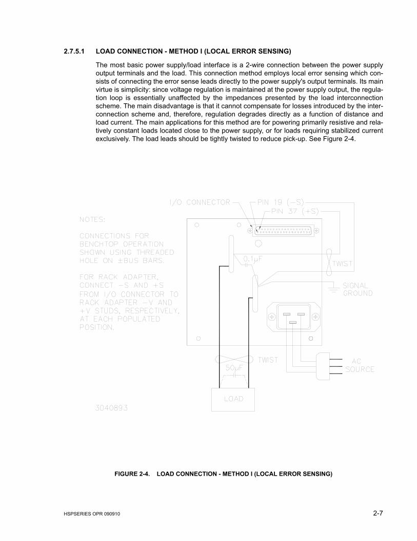
2.7.5.1 LOAD CONNECTION - METHOD I (LOCAL ERROR SENSING)
The most basic power supply/load interface is a 2-wire connection between the power supplyoutput terminals and the load. This connection method employs local error sensing which con-sists of connecting the error sense leads directly to the power supply's output terminals. Its mainvirtue is simplicity: since voltage regulation is maintained at the power supply output, the regula-tion loop is essentially unaffected by the impedances presented by the load interconnectionscheme. The main disadvantage is that it cannot compensate for losses introduced by the inter-connection scheme and, therefore, regulation degrades directly as a function of distance andload current. The main applications for this method are for powering primarily resistive and rela-tively constant loads located close to the power supply, or for loads requiring stabilized currentexclusively. The load leads should be tightly twisted to reduce pick-up. See Figure 2-4.
FIGURE 2-4. LOAD CONNECTION - METHOD I (LOCAL ERROR SENSING)
2-8 HSPSERIES OPR 090910
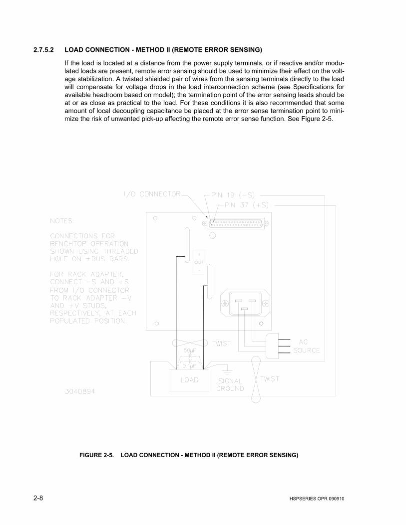
2.7.5.2 LOAD CONNECTION - METHOD II (REMOTE ERROR SENSING)
If the load is located at a distance from the power supply terminals, or if reactive and/or modu-lated loads are present, remote error sensing should be used to minimize their effect on the volt-age stabilization. A twisted shielded pair of wires from the sensing terminals directly to the loadwill compensate for voltage drops in the load interconnection scheme (see Specifications foravailable headroom based on model); the termination point of the error sensing leads should beat or as close as practical to the load. For these conditions it is also recommended that someamount of local decoupling capacitance be placed at the error sense termination point to mini-mize the risk of unwanted pick-up affecting the remote error sense function. See Figure 2-5.
FIGURE 2-5. LOAD CONNECTION - METHOD II (REMOTE ERROR SENSING)
HSPSERIES OPR 090910 2-9
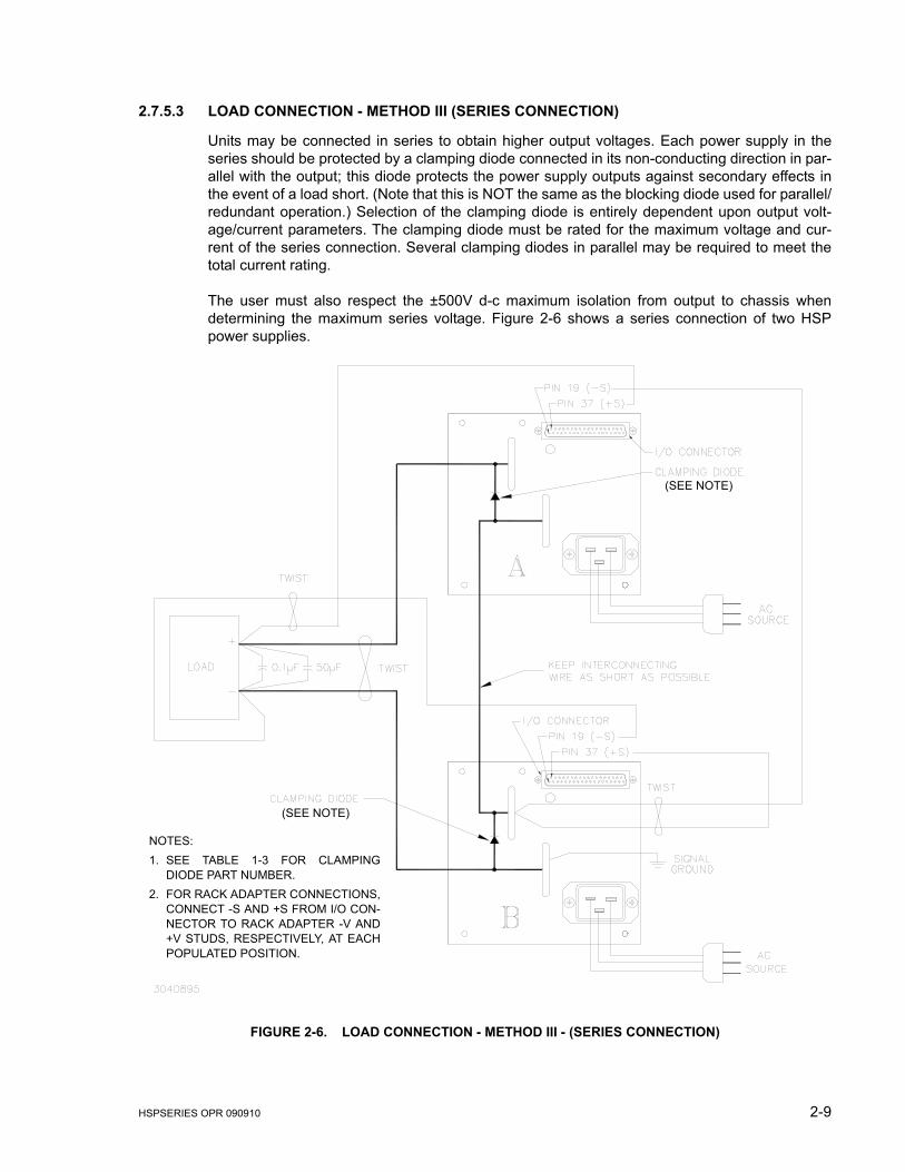
2.7.5.3 LOAD CONNECTION - METHOD III (SERIES CONNECTION)
Units may be connected in series to obtain higher output voltages. Each power supply in theseries should be protected by a clamping diode connected in its non-conducting direction in par-allel with the output; this diode protects the power supply outputs against secondary effects inthe event of a load short. (Note that this is NOT the same as the blocking diode used for parallel/redundant operation.) Selection of the clamping diode is entirely dependent upon output volt-age/current parameters. The clamping diode must be rated for the maximum voltage and cur-rent of the series connection. Several clamping diodes in parallel may be required to meet thetotal current rating.
The user must also respect the ±500V d-c maximum isolation from output to chassis whendetermining the maximum series voltage. Figure 2-6 shows a series connection of two HSPpower supplies.
FIGURE 2-6. LOAD CONNECTION - METHOD III - (SERIES CONNECTION)
NOTES: 1. SEE TABLE 1-3 FOR CLAMPING
DIODE PART NUMBER.2. FOR RACK ADAPTER CONNECTIONS,
CONNECT -S AND +S FROM I/O CON-NECTOR TO RACK ADAPTER -V AND+V STUDS, RESPECTIVELY, AT EACHPOPULATED POSITION.
(SEE NOTE)
(SEE NOTE)

2-10 HSPSERIES OPR 090910
2.7.5.4 LOAD CONNECTION - METHOD IV (PARALLEL OPERATION)
Identical HSP power supply models may be connected in parallel in order to provided increasedoutput current to a common load (see Figure 2-7). This permits the user to obtain significantlyhigher load ratings than for a single HSP power supply. The number of power supplies requiredis determined by dividing the required load current by the current rating of the applicable HSPmodel, and rounding up to the next whole number when necessary. HSP power supplies incor-porate fault detection circuitry which precludes the need for output blocking diodes, and utilizeactive current sharing circuitry to distribute the load current equally among the paralleled units.When operating HSP power supplies in any parallel configuration, load sharing must be imple-mented among the paralleled modules; this is required for proper operation of the fault detector(see PAR. 2.7.6). Figure 2-7 shows a typical parallel configuration using two power supplies;additional parallel modules are added by scaling Figure 2-7.
.
FIGURE 2-7. LOAD CONNECTION - METHOD IV (PARALLEL/REDUNDANT OPERATION WITH HOT-SWAP)
2.7.5.4.1 REDUNDANCY AND HOT SWAP APPLICATIONS
HSP is specifically designed for use in critical applications where power supply redundancy andon-line replacement of defective power supplies (hot-swapping) is required. Redundant opera-tion is achieved by paralleling one or more power supplies in excess of the minimum numberrequired to support the load so that system operation is not compromised by the failure of a sin-gle power supply. Any number of HSP power supplies (N+M) can be wired for redundant opera-tion as long as (N) power supplies can support the load, M representing the total number offailed power supplies.
HSPSERIES OPR 090910 2-11
When operating power supplies in hot-swap applications, the use of an output blocking diode ismandatory to prevent excessive output transients and power connector damage due to arcing atthe output terminals. In applications where redundancy is required but hot-swapping is not, theblocking diode is beneficial in that it adds a layer of isolation between each power supply outputand the common d-c bus, protecting the bus against the possibility of a short at the power sup-ply output. All HSP power supply models are available with this blocking diode internallymounted (“R” suffix option). External mounting of the blocking diode is not recommended,because physical stresses exerted by the load cables or bus bars and improper heat dissipationwill result in premature and undetected failure of the diode.
2.7.6 LOAD SHARING
When operating two or more power supplies in parallel, either for capacity or redundancy, it isdesirable to distribute the load equally among all of the power supplies in order to improve per-formance, reduce stress and increase reliability. HSP power supplies incorporate active circuitrywhich forces multiple power supplies wired in parallel to share load current, both in voltage- andcurrent-mode regulation. The HSP employs a single wire connection between paralleled powersupplies, forming a master-slave relationship as follows: the highest voltage unit becomes themaster, and all of the remaining units are slaved to it via the load share signal (ISHARE), whichboosts the slave outputs in order to increase load share. A maximum boost limit of 5% preventsthe slave units from following a defective master into an overvoltage condition, or from creatinga load hazard if either the slave itself or the load sharing system is defective.
When implementing load sharing, the user must ensure that all power supplies are attempting toregulate to the same voltage at the same location, and must minimize the possibility of loadshare signal corruption; the power supplies should, as nearly as possible, emulate a single largepower supply. To this end, the following rules apply:
a. If possible, remote error sensing should be employed, with all error sensing connections ter-minated at the same physical point, and as close to the power supplies as possible; if localerror sensing is required, power lead voltage drops must be minimized. Provide local noisedecoupling capacitors across all sense wire termination points.
b. The power supplies should be located as near to each other as possible, with power termina-tions bussed together using adequately sized interconnections; the power supply/load inter-connections should be distributed evenly along the power supply output interconnection bus-ses. This is especially important in high-current systems employing several power supplymodules in parallel, where voltage drops in the interface connections can be significant incomparison to the load share signal voltage and introduce both d-c and a-c errors.
c. All power supply output voltages should be adjusted as closely as possible, and in any casewithin a 2% error band. Additionally, the current limit setpoints should be identical and highenough to support the load requirements; for (N+M) systems, this means setting the currentlimits high enough to tolerate loss of M power supplies and still support the load.
d. Minimize the load share signal wire interconnection lengths to reduce risk of noise influence.

2-12 HSPSERIES OPR 090910
2.7.7 SIGNAL CONNECTIONS
The I/O Signal Connector, located on the rear panel of the HSP power supply (see Figure 2-3),provides access for all programming inputs and status signal outputs. These signals provide theuser access to portions of the regulation control circuitry of the HSP and, as such, must be pro-tected from radiated and conducted noise as well as from physical contact with non-valid drivingsources. The following subsections address specific programming signal applications; in gen-eral, however, when accessing this connector from distant locations or high-noise environ-ments, it is recommended that a shielded cable be used, with the shield terminated to thesystem's single point ground.
a. Remote Error Sense Twist positive and negative error sensing lines (pins 37,19) together, especially when a sig-nificant distance separates the power supply and load.
b. External Voltage Programming (Voltage or Current)Twist the programming signal line(s) (pins 18, 15, or both 18 and 15) with negative errorsensing line (pin 19); use shielded cable if possible.
c. External Resistance Programming (Voltage)Twist both programming lines (pins 17, 35) together; use shielded cable if possible.
d. Remote Inhibit Controls (RC1, RC2)Twist either (or both) programming lines (pins 7,8) together with AUXRTN (pin 25); if 5VAUXis used to power the external inhibit control circuitry, include 5VAUX line (pin 26) in twist.
2.8 MECHANICAL KEYING
When used with Kepco plug-in rack adapters (RA 60 and similar), HSP power supplies canbe configured for extraction from and insertion to an active system, or “hot-swap”. Hot-swapping requires the use of series blocking diodes for each output (see Figure 2-7). TheHSP incorporates a mechanical keying system to be used in conjunction with the plug-inrack adapters to prevent installation of any but the correct model HSP in a given position.The keying mechanism is comprised of (7) holes, each corresponding to an HSP model; allholes are plugged except for the “keyway,” thus providing the keying function in conjunctionwith a pin installed in each rack adapter position. All HSP power supplies are keyed by volt-age at the factory. It is essential that the user: 1) not remove or alter the keyway plugs,and 2) replace any plugs which are inadvertently removed in accordance with theview shown in Figure 2-3. To change module keying, see instructions accompanying theHSP series plug-in rack adapters.
2.9 RETAINING LATCHES
HSP series power supplies are provided with (2) retention latches located at each side of thebottom edge of the front panel (see Figure 2-1). These latches work in conjunction with the HSPseries plug-in rack adapters to prevent unauthorized or inadvertent module extraction from anoperating power system. The latch is engaged by loosening the cap-head screw approximately1/2 turn CCW (use 5/32" hex key) and sliding the latch down to the bottom of the slot, thenretightening the cap-head screw CW until snug. DO NOT OVERTIGHTEN! To release, followthe same procedure, except lift the latch to the top of the slot. Be sure to move the latch com-pletely up or down to ensure full engagement and disengagement of the latching mechanism.When the HSP power supply is not installed in its plug-in rack adapter, it is recommended thatthe latch be secured in the open (up) position to prevent damage.
NOTE: Retaining latches must not be used to secure the HSP power supply in the rackadapter for shipping purposes.
HSPSERIES OPR 090910 3-1
SECTION 3 - OPERATING INSTRUCTIONS
3.1 OPERATING CONFIGURATION
The following subsections review the various features and indicate how to select and operateeach function. The default settings for each function indicate the as-shipped status for standardHSP series power supplies. Prior to applying source power, the operating configuration of theHSP power supply must be selected. This setup is performed via the multiposition configurationswitches S1, S2 and S3 which are accessed via slots in the top cover (see Figure 2-2), while theexternal control signals (programming input and status output) are accessed via the I/O Con-nector on the rear panel of the HSP power supply (see Figure 2-3).
HSP series power supplies incorporate several advanced features which expand their applica-bility beyond that of simple voltage stabilizers. These functions include both internal and exter-nal programming of voltage and current regulation points, remote error sensing, active loadsharing circuitry, output overvoltage and undervoltage protection, output current “walk-in,” in-cir-cuit voltage and current setpoint monitors, and dual-mode floating inhibit controls, as well asForm-C relay contact outputs indicating source, output and fan status, and overtemperatureshutdown.
3.2 REMOTE ERROR SENSE
All HSP power supplies are equipped with remote error sensing to compensate for the voltagedrop inherent in any power supply/load interconnection scheme. The amount of compensationvaries based on output voltage: 3.3V and 5V models compensate up to 0.25V drop in eachpower lead (0.5V total), while 12V through 48V models provide for up to 0.8V drop in each lead(1.6V total). The remote error sense leads must be connected to the output power termi-nations, either locally at the power supply output terminals or remotely at the load termi-nations, using the correct polarity, for the HSP to operate properly. (See Figures 2-4through 2-7.)
3.3 OUTPUT VOLTAGE PROGRAMMING
HSP power supplies provide three different methods for programming the output voltage regula-tion point: internal, external resistance and external voltage. When using either internal or exter-nal resistance programming, the minimum programmable voltage is 50-60% of nominal, whileexternal voltage programming permits adjustment down to zero. Performance specifications areonly guaranteed over the range shown in Table 1-1. The programming method is selected viaS2 switch positions 3, 4 and 5 as follows:
NOTE: One programming mode must be selected, or the HSP output voltage programs tozero; never select more than one programming mode at a time.
a) Internal Programming: This is the factory-set (default) mode (see Figure 2-2); whenenabled via S2-5, the output voltage is adjusted via the front panel potentiometer labeled“VO” (see Figure 2-1).
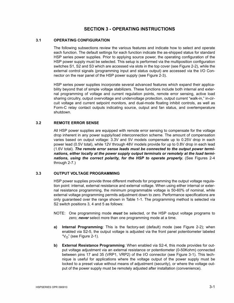
b) External Resistance Programming: When enabled via S2-4, this mode provides for out-put voltage adjustment via an external resistance or potentiometer (0-50Kohm) connectedbetween pins 17 and 35 (VRP1, VRP2) of the I/O connector (see Figure 3-1). This tech-nique is useful for applications where the voltage output of the power supply must belocked to a preset value without means of adjustment (security), or where the voltage out-put of the power supply must be remotely adjusted after installation (convenience).
3-2 HSPSERIES OPR 090910
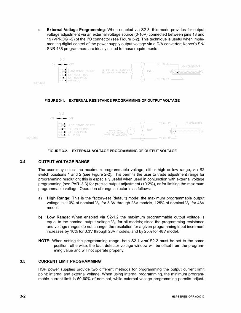
c External Voltage Programming: When enabled via S2-3, this mode provides for outputvoltage adjustment via an external voltage source (0-10V) connected between pins 18 and19 (VPROG, -S) of the I/O connector (see Figure 3-2). This technique is useful when imple-menting digital control of the power supply output voltage via a D/A converter; Kepco's SN/SNR 488 programmers are ideally suited to these requirements
FIGURE 3-1. EXTERNAL RESISTANCE PROGRAMMING OF OUTPUT VOLTAGE
FIGURE 3-2. EXTERNAL VOLTAGE PROGRAMMING OF OUTPUT VOLTAGE
3.4 OUTPUT VOLTAGE RANGE
The user may select the maximum programmable voltage, either high or low range, via S2switch positions 1 and 2 (see Figure 2-2). This permits the user to trade adjustment range forprogramming resolution; this is especially useful when used in conjunction with external voltageprogramming (see PAR. 3.3) for precise output adjustment (±0.2%), or for limiting the maximumprogrammable voltage. Operation of range selector is as follows:
a) High Range: This is the factory-set (default) mode; the maximum programmable outputvoltage is 110% of nominal VO for 3.3V through 28V models, 125% of nominal VO for 48Vmodel.
b) Low Range: When enabled via S2-1,2 the maximum programmable output voltage isequal to the nominal output voltage VO for all models; since the programming resistanceand voltage ranges do not change, the resolution for a given programming input incrementincreases by 10% for 3.3V through 28V models, and by 25% for 48V model.
NOTE: When setting the programming range, both S2-1 and S2-2 must be set to the sameposition; otherwise, the fault detector voltage window will be offset from the program-ming value and will not operate properly.
3.5 CURRENT LIMIT PROGRAMMING
HSP power supplies provide two different methods for programming the output current limitpoint: internal and external voltage. When using internal programming, the minimum program-mable current limit is 50-60% of nominal, while external voltage programming permits adjust-
HSPSERIES OPR 090910 3-3
ment down to near zero. The programming method is selected via S3 switch positions 2 and 3as follows:
NOTE: One programming mode must be selected, or the HSP current limit programs to zero;never select more than one programming mode at a time.
a) Internal Programming: This is the factory-set (default) mode (see Figure 2-2); whenenabled via S3-3, the current limit is adjusted via the front panel potentiometer labeled“IMAX” (see Figure 2-1).
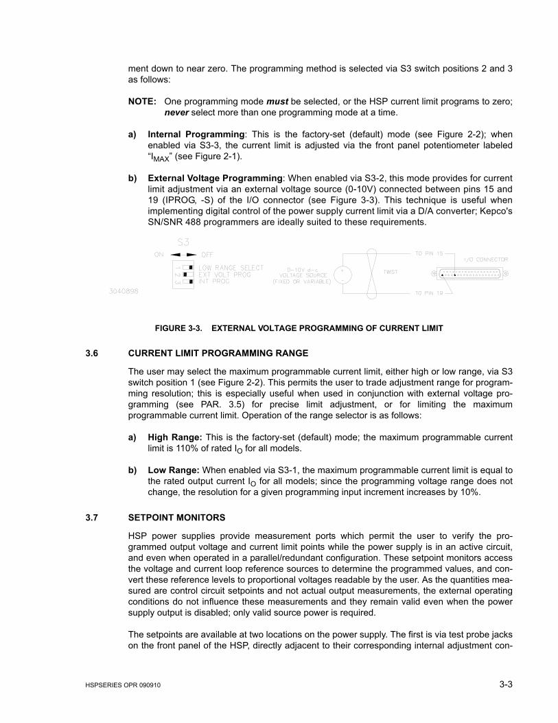
b) External Voltage Programming: When enabled via S3-2, this mode provides for currentlimit adjustment via an external voltage source (0-10V) connected between pins 15 and19 (IPROG, -S) of the I/O connector (see Figure 3-3). This technique is useful whenimplementing digital control of the power supply current limit via a D/A converter; Kepco'sSN/SNR 488 programmers are ideally suited to these requirements.
FIGURE 3-3. EXTERNAL VOLTAGE PROGRAMMING OF CURRENT LIMIT
3.6 CURRENT LIMIT PROGRAMMING RANGE
The user may select the maximum programmable current limit, either high or low range, via S3switch position 1 (see Figure 2-2). This permits the user to trade adjustment range for program-ming resolution; this is especially useful when used in conjunction with external voltage pro-gramming (see PAR. 3.5) for precise limit adjustment, or for limiting the maximumprogrammable current limit. Operation of the range selector is as follows:
a) High Range: This is the factory-set (default) mode; the maximum programmable currentlimit is 110% of rated IO for all models.
b) Low Range: When enabled via S3-1, the maximum programmable current limit is equal tothe rated output current IO for all models; since the programming voltage range does notchange, the resolution for a given programming input increment increases by 10%.
3.7 SETPOINT MONITORS
HSP power supplies provide measurement ports which permit the user to verify the pro-grammed output voltage and current limit points while the power supply is in an active circuit,and even when operated in a parallel/redundant configuration. These setpoint monitors accessthe voltage and current loop reference sources to determine the programmed values, and con-vert these reference levels to proportional voltages readable by the user. As the quantities mea-sured are control circuit setpoints and not actual output measurements, the external operatingconditions do not influence these measurements and they remain valid even when the powersupply output is disabled; only valid source power is required.
The setpoints are available at two locations on the power supply. The first is via test probe jackson the front panel of the HSP, directly adjacent to their corresponding internal adjustment con-
3-4 HSPSERIES OPR 090910
trols (see Figure 2-1); the jacks are labeled VO and IMAX, with a third test point labeled COMproviding access to the circuit return. The second location is the I/O connector: here, the testpoints are labeled VSET and ISET, and are available at pins 36 and 33, respectively, with circuitreturn accessed at pin 19 (-S) (see Figure 2-3).
Measurement quantities are defined as follows:
VO, VSET: This voltage represents 1/10 of the programmed output voltage. As an example,VSET (or VO) = 4.63V corresponds to a programmed output voltage of 46.3V ±1%.This relationship is constant, regardless of the programming range selected (seePAR. 3.4).
IMAX, ISET: This voltage represents the percentage of available power supply current as a per-centage of rated current, with 10V corresponding to 100%; available current isdefined as the maximum current limit available based on the programming range(see PAR. 3.6). Unlike VSET, ISET is always based on a 0-10V scale, regardless ofthe range selected. For example, ISET (or IMAX) = 6.2V corresponds to 62% of themaximum programmable current; for the low programming range, this correspondsto 62% of the rated module current, but for the high programming range the num-ber is 62% of 110%, or 68.2% of rated module current. If the module is HSP 5-200,for example, the programmed current limit is either 124A or 136.4A, depending onthe range selection. Current setpoint monitor accuracy is ±5%.
3.8 OVERVOLTAGE PROTECTION ADJUSTMENT
HSP power supplies incorporate output overvoltage protection (OVP) circuitry which latchesthe output regulator off in the event that the output voltage rises above a predetermined level.Reset requires that the user remove source power for a minimum of 30 seconds (optionalremote reset is described in PAR. 3.12). The trip level is preset at the factory for 130% of thenominal output voltage (see Table 1-1), however, this level can be adjusted from 100% to140% of the nominal output (except Model HSP 48-21, which can be adjusted from 100% to160% of the nominal output) via the OVP ADJUST control accessed through the top cover(see Figure 2-2). To set the trip level to a new value, perform the following steps:
NOTE: For 48V Models only, do not set OVP trip level above 63V.
1. Disconnect any external load circuitry which may be damaged by excessive voltage; a mini-mum load of 5W is recommended (see PAR. 2.5, step 3).
2. With source power removed, connect load as shown in Figure 2-4 for local sensing, exceptremove connection between I/O connector pin 37 (+S) and the output bus bar and substitutea 20K ohm potentiometer between pin 37 and the output bus bar; adjust the pot for minimumresistance.
3. Rotate OVP ADJUST control on HSP fully clockwise.
4. Apply source power; while monitoring voltage at output terminals (bus bars), increase exter-nal pot resistance until the output voltage is set for the desired overvoltage protection value.
5. Slowly rotate the OVP ADJUST pot counterclockwise until the output is latched off (voltagedrops rapidly toward zero); the overvoltage trip level is now adjusted to the desired overvolt-age protection value (step 4, above).
6. Remove source power for at least 30 seconds, or until the front panel indicator LEDs beginto blink; reduce the external pot resistance slightly, and reapply source power.
7. While monitoring the output voltage, slowly increase the pot resistance until the output shutsdown, and verify trip set point; if necessary, repeat steps 3 through 6 above.
HSPSERIES OPR 090910 3-5
The signal generated by the OVP detector is gated with a signal from the fault detector circuit toproduce a selective overvoltage shutdown function which prevents shutdown of operationalpower supplies in a parallel-redundant power system configuration. The OVP latches of anyworking power supplies are disabled, allowing only the faulty modules to be latched off; systemoperation can then return to normal, assuming sufficient load capacity in the remaining modulesto support the load. This function is critical in fault-tolerant power systems, otherwise a singleovervoltage failure could ripple through all of the operating supplies and result in a completepower system loss.
NOTE: The overvoltage protection circuit senses the voltage directly at the output terminalsof the power supply, not at the error sensing point. When selecting an overvoltage setpoint, the user must take into account the expected power lead voltage drop and, ifapplicable, the transient response overshoot in order to avoid false shutdowns. TheHSP design is such that the power supply cannot generate an output voltage highenough to cause internal damage, regardless of OVP setting.
3.9 CURRENT LIMIT CHARACTERISTIC
HSP power supplies provide two different current limiting modes for different applications; selec-tion of the desired mode is accomplished via switch S1-3, accessed through the top cover of theHSP (see Figure 2-2). The following describes the operational differences and selection methodof each:
a) Continuous Limiting: This is the factory-set (default) mode of operation. When the outputcurrent of the power supply reaches the programmed current limit, the output regulatorswitches to current mode operation and maintains the output current by modulating theoutput voltage; this operating mode is maintained indefinitely, and recovery to voltage reg-ulation mode is automatic upon reduction of the output current below the current limit point.This mode is ideal for high-power battery chargers and applications where operation in cur-rent regulation mode is normal, or where immediate recovery from an overload condition ofany duration is critical.
NOTE: HSP power supplies are designed to maintain continuous delivery of 110% of ratedcurrent indefinitely. When operating parallel/redundant power supply configurations incontinuous limiting mode, the user must size the power supply/load interconnectionconductors to withstand the total maximum load current available from all of the paral-leled power supply modules.
b) Undervoltage Lockout: This mode is enabled when S1-3 is set to ON (Figure 2-2). Thecrossover from voltage- to current-mode operation is the same as for Continuous Limiting;however, after approximately 15 seconds, the output load regulation circuit is locked off viathe overvoltage protection latch, requiring the user to recycle source power to restart thepower supply (see PAR. 3.8). This mode permits automatic recovery from short-term over-loads, but eliminates the danger of overheating and damage to the load and load wiringdue to continuous exposure to high current; this is especially useful in redundant powersystems, where the continuous overload current of all of the paralleled power supply mod-ules can be in excess of twice the normal load current. As the circuit is triggered by theoccurrence of an output undervoltage condition, this circuit can also protect circuits whichmay be unduly stressed in the presence of an extended undervoltage condition; an exam-ple of this are batteries, which can be damaged by discharge voltages below a specifiedminimum.
NOTE: When undervoltage lockout mode is enabled, it is necessary to also enable theRemote Reset function (see PAR. 3.12) in order for the Remote Inhibit function to oper-ate properly.
3-6 HSPSERIES OPR 090910
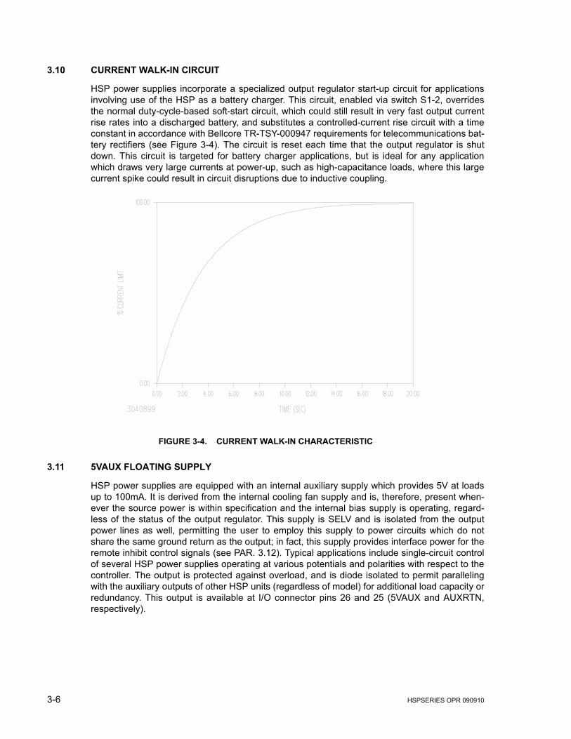
3.10 CURRENT WALK-IN CIRCUIT
HSP power supplies incorporate a specialized output regulator start-up circuit for applicationsinvolving use of the HSP as a battery charger. This circuit, enabled via switch S1-2, overridesthe normal duty-cycle-based soft-start circuit, which could still result in very fast output currentrise rates into a discharged battery, and substitutes a controlled-current rise circuit with a timeconstant in accordance with Bellcore TR-TSY-000947 requirements for telecommunications bat-tery rectifiers (see Figure 3-4). The circuit is reset each time that the output regulator is shutdown. This circuit is targeted for battery charger applications, but is ideal for any applicationwhich draws very large currents at power-up, such as high-capacitance loads, where this largecurrent spike could result in circuit disruptions due to inductive coupling.
FIGURE 3-4. CURRENT WALK-IN CHARACTERISTIC
3.11 5VAUX FLOATING SUPPLY
HSP power supplies are equipped with an internal auxiliary supply which provides 5V at loadsup to 100mA. It is derived from the internal cooling fan supply and is, therefore, present when-ever the source power is within specification and the internal bias supply is operating, regard-less of the status of the output regulator. This supply is SELV and is isolated from the outputpower lines as well, permitting the user to employ this supply to power circuits which do notshare the same ground return as the output; in fact, this supply provides interface power for theremote inhibit control signals (see PAR. 3.12). Typical applications include single-circuit controlof several HSP power supplies operating at various potentials and polarities with respect to thecontroller. The output is protected against overload, and is diode isolated to permit parallelingwith the auxiliary outputs of other HSP units (regardless of model) for additional load capacity orredundancy. This output is available at I/O connector pins 26 and 25 (5VAUX and AUXRTN,respectively).
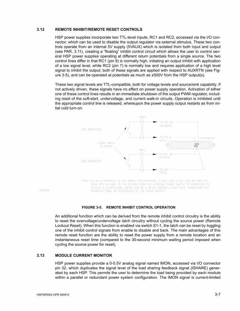
HSPSERIES OPR 090910 3-7
3.12 REMOTE INHIBIT/REMOTE RESET CONTROLS
HSP power supplies incorporate two TTL-level inputs, RC1 and RC2, accessed via the I/O con-nector, which can be used to disable the output regulator via external stimulus. These two con-trols operate from an internal 5V supply (5VAUX) which is isolated from both input and output(see PAR. 3.11), creating a “floating” inhibit control circuit which allows the user to control sev-eral HSP power supplies operating at different return potentials from a single source. The twocontrol lines differ in that RC1 (pin 8) is normally high, initiating an output inhibit with applicationof a low signal level, while RC2 (pin 7) is normally low and requires application of a high levelsignal to inhibit the output; both of these signals are applied with respect to AUXRTN (see Fig-ure 3-5), and can be operated at potentials as much as ±500V from the HSP output(s).
These two signal levels are TTL-compatible, both for voltage levels and source/sink capability. Ifnot actively driven, these signals have no effect on power supply operation. Activation of eitherone of these control lines results in an immediate shutdown of the output PWM regulator, includ-ing reset of the soft-start, undervoltage, and current walk-in circuits. Operation is inhibited untilthe appropriate control line is released, whereupon the power supply output restarts as from ini-tial cold turn-on.
FIGURE 3-5. REMOTE INHIBIT CONTROL OPERATION
An additional function which can be derived from the remote inhibit control circuitry is the abilityto reset the overvoltage/undervoltage latch circuitry without cycling the source power (RemoteLockout Reset). When this function is enabled via switch S1-1, the latch can be reset by togglingone of the inhibit control signals from enable to disable and back. The main advantages of thisremote reset function are the ability to reset the power supply from a remote location and aninstantaneous reset time (compared to the 30-second minimum waiting period imposed whencycling the source power for reset).
3.13 MODULE CURRENT MONITOR
HSP power supplies provide a 0-5.5V analog signal named IMON, accessed via I/O connectorpin 32, which duplicates the signal level of the load sharing feedback signal (ISHARE) gener-ated by each HSP. This permits the user to determine the load being provided by each modulewithin a parallel or redundant power system configuration. The IMON signal is current-limited
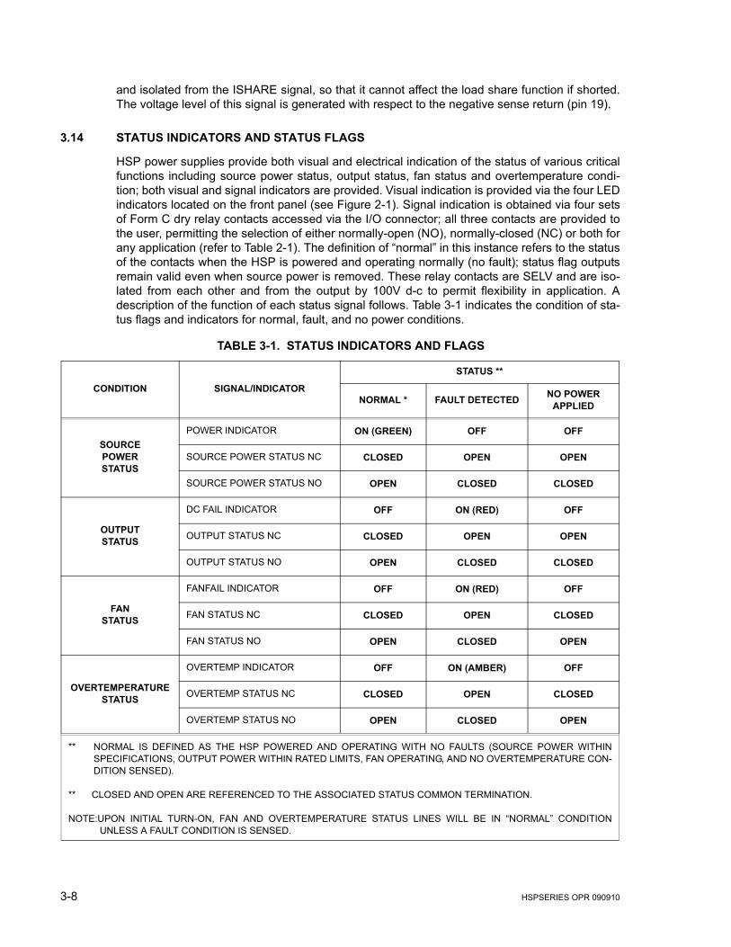
3-8 HSPSERIES OPR 090910
and isolated from the ISHARE signal, so that it cannot affect the load share function if shorted.The voltage level of this signal is generated with respect to the negative sense return (pin 19).
3.14 STATUS INDICATORS AND STATUS FLAGS
HSP power supplies provide both visual and electrical indication of the status of various criticalfunctions including source power status, output status, fan status and overtemperature condi-tion; both visual and signal indicators are provided. Visual indication is provided via the four LEDindicators located on the front panel (see Figure 2-1). Signal indication is obtained via four setsof Form C dry relay contacts accessed via the I/O connector; all three contacts are provided tothe user, permitting the selection of either normally-open (NO), normally-closed (NC) or both forany application (refer to Table 2-1). The definition of “normal” in this instance refers to the statusof the contacts when the HSP is powered and operating normally (no fault); status flag outputsremain valid even when source power is removed. These relay contacts are SELV and are iso-lated from each other and from the output by 100V d-c to permit flexibility in application. Adescription of the function of each status signal follows. Table 3-1 indicates the condition of sta-tus flags and indicators for normal, fault, and no power conditions.
TABLE 3-1. STATUS INDICATORS AND FLAGS
CONDITION SIGNAL/INDICATOR
STATUS **
NORMAL * FAULT DETECTED NO POWER APPLIED
SOURCEPOWERSTATUS
POWER INDICATOR ON (GREEN) OFF OFF
SOURCE POWER STATUS NC CLOSED OPEN OPEN
SOURCE POWER STATUS NO OPEN CLOSED CLOSED
OUTPUTSTATUS
DC FAIL INDICATOR OFF ON (RED) OFF
OUTPUT STATUS NC CLOSED OPEN OPEN
OUTPUT STATUS NO OPEN CLOSED CLOSED
FANSTATUS
FANFAIL INDICATOR OFF ON (RED) OFF
FAN STATUS NC CLOSED OPEN CLOSED
FAN STATUS NO OPEN CLOSED OPEN
OVERTEMPERATURESTATUS
OVERTEMP INDICATOR OFF ON (AMBER) OFF
OVERTEMP STATUS NC CLOSED OPEN CLOSED
OVERTEMP STATUS NO OPEN CLOSED OPEN
** NORMAL IS DEFINED AS THE HSP POWERED AND OPERATING WITH NO FAULTS (SOURCE POWER WITHINSPECIFICATIONS, OUTPUT POWER WITHIN RATED LIMITS, FAN OPERATING, AND NO OVERTEMPERATURE CON-DITION SENSED).
** CLOSED AND OPEN ARE REFERENCED TO THE ASSOCIATED STATUS COMMON TERMINATION.
NOTE:UPON INITIAL TURN-ON, FAN AND OVERTEMPERATURE STATUS LINES WILL BE IN “NORMAL” CONDITIONUNLESS A FAULT CONDITION IS SENSED.
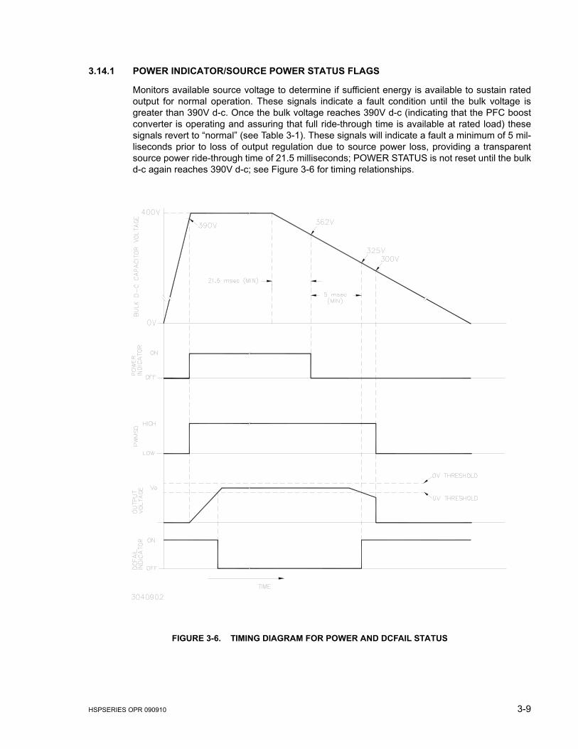
HSPSERIES OPR 090910 3-9
3.14.1 POWER INDICATOR/SOURCE POWER STATUS FLAGS
Monitors available source voltage to determine if sufficient energy is available to sustain ratedoutput for normal operation. These signals indicate a fault condition until the bulk voltage isgreater than 390V d-c. Once the bulk voltage reaches 390V d-c (indicating that the PFC boostconverter is operating and assuring that full ride-through time is available at rated load) thesesignals revert to “normal” (see Table 3-1). These signals will indicate a fault a minimum of 5 mil-liseconds prior to loss of output regulation due to source power loss, providing a transparentsource power ride-through time of 21.5 milliseconds; POWER STATUS is not reset until the bulkd-c again reaches 390V d-c; see Figure 3-6 for timing relationships.
FIGURE 3-6. TIMING DIAGRAM FOR POWER AND DCFAIL STATUS
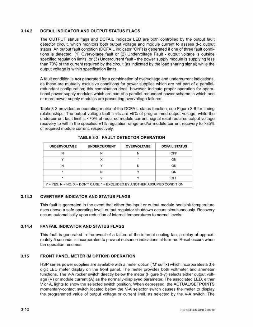
3-10 HSPSERIES OPR 090910
3.14.2 DCFAIL INDICATOR AND OUTPUT STATUS FLAGS
The OUTPUT status flags and DCFAIL indicator LED are both controlled by the output faultdetector circuit, which monitors both output voltage and module current to assess d-c outputstatus. An output fault condition (DCFAIL indicator “ON”) is generated if one of three fault condi-tions is detected: (1) Overvoltage fault or (2) Undervoltage Fault - output voltage is outsidespecified regulation limits, or (3) Undercurrent fault - the power supply module is supplying lessthan 70% of the current required by the circuit (as indicated by the load sharing signal) while theoutput voltage is within specification limits.
A fault condition is not generated for a combination of overvoltage and undercurrent indications,as these are mutually exclusive conditions for power supplies which are not part of a parallel-redundant configuration; this combination does, however, indicate proper operation for opera-tional power supply modules which are part of a parallel-redundant power scheme in which oneor more power supply modules are presenting overvoltage failures.
Table 3-2 provides an operating matrix of the DCFAIL status function; see Figure 3-6 for timingrelationships. The output voltage fault limits are ±5% of programmed output voltage, while theundercurrent fault limit is <70% of required module current; signal reset requires output voltagerecovery to within the specified ±1% regulation range and/or module current recovery to >85%of required module current, respectively.
3.14.3 OVERTEMP INDICATOR AND STATUS FLAGS
This fault is generated in the event that either the input or output module heatsink temperaturerises above a safe operating level; output regulator shutdown occurs simultaneously. Recoveryoccurs automatically upon reduction of internal temperatures to normal levels.
3.14.4 FANFAIL INDICATOR AND STATUS FLAGS
This fault is generated in the event of a failure of the internal cooling fan; a delay of approxi-mately 5 seconds is incorporated to prevent nuisance indications at turn-on. Reset occurs whenfan operation resumes.
3.15 FRONT PANEL METER (M OPTION) OPERATION
HSP series power supplies are available with a meter option (‘M' suffix) which incorporates a 3½digit LED meter display on the front panel. The meter provides both voltmeter and ammeterfunctions. The V-A rocker switch directly below the meter (Figure 3-7) selects either output volt-age (V) or module current (A) as the normally-displayed parameter. The associated LED, eitherV or A, lights to show the selected switch position. When depressed, the ACTUAL/SETPOINTSmomentary-contact switch located below the V-A selector switch causes the meter to displaythe programmed value of output voltage or current limit, as selected by the V-A switch. The
TABLE 3-2. FAULT DETECTOR OPERATION
UNDERVOLTAGE UNDERCURRENT OVERVOLTAGE DCFAIL STATUS
N N N OFF
Y X * ON
N Y N ON
* N Y ON
* Y Y OFF
Y = YES; N = NO; X = DON'T CARE; * = EXCLUDED BY ANOTHER ASSUMED CONDITION
HSPSERIES OPR 090910 3-11
operation of the fault detector remains unaffected by the inclusion of the meter option. The fol-lowing paragraphs describe the meter functions in detail.
3.15.1 VOLTMETER OPERATION
With the V-A selector switch set to ‘V' position (green V indicator illuminated), the meter nor-mally displays the actual output voltage present at the error sense terminals. If the ACTUAL/SETPOINTS switch is depressed with the V-A selector switch set to V, the display shows theprogrammed output voltage (±1%) of that module, regardless of the actual output status at thetime (refer to VSET, PAR. 3.7); unlike VSET, however, both actual and setpoint voltages are dis-played in volts. If desired, the programmed setpoint can be adjusted using the previouslyselected output voltage programming method (PAR. 3.3). Releasing the ACTUAL/SETPOINTSswitch causes the meter to resume displaying actual output voltage.
3.15.2 AMMETER OPERATION
With the V-A selector switch set to ‘A' position (amber A indicator illuminated), the meter nor-mally displays the actual output current (within ±12%) presently being supplied by the module. Ifthe ACTUAL/SETPOINTS switch is depressed with the V-A selector switch set to I, the displayshows the programmed current limit (±1%) of that module, regardless of the actual current beingsupplied at the time (ref. ISET, PAR. 3.7); unlike ISET and ISHARE, however, both actual cur-rent and setpoint current limit are displayed in amperes. If desired, the programmed setpoint forcurrent limit can be adjusted using the previously selected current limit programming method(PAR. 3.5). Releasing the ACTUAL/SETPOINTS switch causes the meter to resume displayingactual module output current.
NOTE: Ammeter accuracy of ±12% applies for load currents between 25 and 100% of ratedoutput current (e.g., between 50 and 200 Amperes for HSP 5-200). For load currentsless than 25%, ammeter accuracy degrades significantly.
3.15.3 PARALLEL/REDUNDANT OPERATION
The display function is fully operational when HSP is used either singly, as a stand-alone powersupply, or in multiples, as part of a parallel/redundant or series load arrangement. When used aspart of a parallel/redundant power system, however, the following points should be noted.
When the meters are functioning as voltmeters:
• The actual voltage displayed by each power supply module represents the output bus voltage, and not the individual voltage supplied by each module.
• The setpoint function, however, does display the individual setting for the specific power supply module being measured, thus allowing on-line calibration of all of the power sup-ply modules in the system.
When the meters are functioning as ammeters,
• The actual current displayed by each power supply module represents actual module output current regardless of output configuration.
• The setpoint function for current limit displays the individual setting for the specific power supply module being measured,

3-12 HSPSERIES OPR 090910
3.16 BATTERY (B OPTION) OPERATION
The Battery Charger Option (B suffix) adds a second switch-selectable voltage network to thefront panel. This permits the user to preset two different voltage regulation values correspondingto “float” and “equalize” functions for battery charging applications. This option is available for1000W HSP models covering 12V, 24V and 48V, and 1500W models covering 24V and 48Vnominal battery voltages.
When the Float-Equalize switch is set to FL (see Figure 3-7), the Float potentiometer adjusts theoutput voltage; when set to EQ, the Equalize potentiometer adjusts the output voltage. The FL-EQ position also determines which voltage is available at test point Vo. CAUTION: Adjusting thenon-selected potentiometer (e.g., FL potentiometer with switch set to EQ) can have adverseeffects, because an unknown output voltage will be applied to the load when the switch positionis changed. The fault detector window is altered to accommodate the normal range of batteryvoltage from fully discharged to peak equalize charge as shown in Table 3-3.:
The programmed current limit (Imax) applies to both float and Equalize operation. If the Moption is also included, the meters operate as described above (see PAR. 3.15) except that thedisplayed setpoint value is determined by the FL-EQ switch.
FIGURE 3-7. HSP M (METER) OPTION AND B (BATTERY CHARGER) OPTION, FRONT PANEL
TABLE 3-3. B OPTION FAULT DETECTION WINDOW
NOMINAL BATTERY VOLTAGE KEPCO MODEL MIN. VOLTS MAX. VOLTS
12V HSP 15-66B 10.6 14.6
24V HSP 28-36B, HSP 28-53B 21.1 29.2
48V HSP 48-21B, HSP 48-30B 42.2 58.4