Embed Size (px)
Citation preview
alto-shaam.com
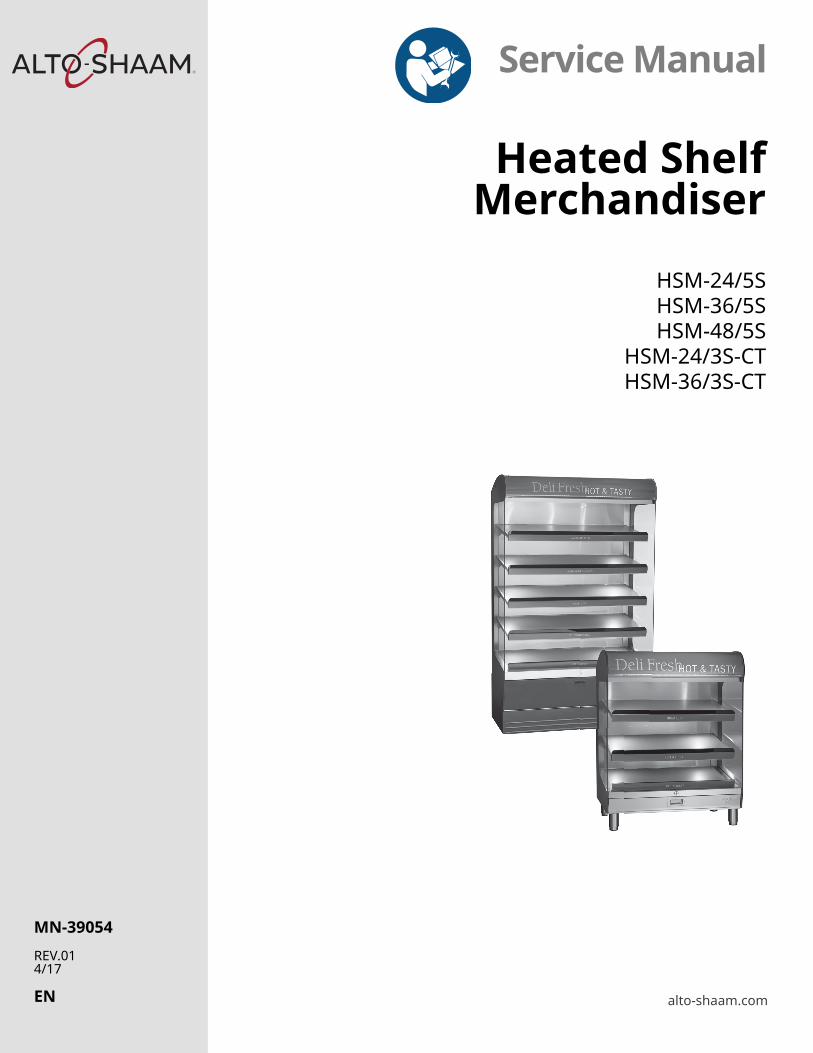
Service Manual
Heated ShelfMerchandiser
HSM-24/5SHSM-36/5SHSM-48/5S
HSM-24/3S-CTHSM-36/3S-CT
MN-39054
REV.014/17
EN
Manufacturer’s Information
Copyright © Copyright 4/17 by Alto-Shaam, Inc.
All rights reserved.
This manual or any portion thereof may not be reproduced or used in any manner whatsoever without the express written permission of Alto-Shaam, Inc.
Trademarks All trademarks referenced in this documentation are the property of their respective owners.
Manufacturer Alto-Shaam, Inc.
P.O. Box 450
W164 N9221 Water Street
Menomonee Falls, WI 53052
Original instructions The content in this manual is written in American English.
User profile The servicer of this appliance must be a qualified and trained Alto-Shaam service partner.
FORWARD
Heated Shelf Merchandiser ? Service Manual ? MN-39054 ? Rev 1 ? 4/17
3
OR
WA
RD
Alto-Shaam 24/7 Emergency Repair Service
Call Call 800-558-8744 to reach our twenty-four hour emergency service call center for immediate access to local authorized service agencies outside standard business hours. The emergency service access is provided exclusively for Alto-Shaam equipment and is available throughout the United States through Alto-Shaam’s toll free number.
Availability Emergency service access is available seven days a week, including holidays.

FORWARD
Heated Shelf Merchandiser ? Service Manual ? MN-39054 ? Rev 1 ? 4/17
4
TABLE OF CONTENTS
Heated Shelf Merchandiser ? Service Manual ? MN-39054 ? Rev 1 ? 4/17
5
TAB
LE O
F C
ON
TEN
TS
Manufacturer’s Information . . . . . . . . . . . . . . . . . . . . . . . . 2
Forward 3 Alto-Shaam 24/7 Emergency Repair Service . . . . . . . . . . . . . . . 3
Table of Contents 5
Safety 7The Meaning of Signal Words . . . . . . . . . . . . . . . . . . . . . . . 7Safety Precautions. . . . . . . . . . . . . . . . . . . . . . . . . . . . . . 8
Operation 11Operating the Merchandiser. . . . . . . . . . . . . . . . . . . . . . . . 11
Components 12Component Identification . . . . . . . . . . . . . . . . . . . . . . . . . 12HSM-CT Component Access Panels . . . . . . . . . . . . . . . . . . . . 14HSM-5S Component Access Panels . . . . . . . . . . . . . . . . . . . . 15HSM—Electrical Assembly . . . . . . . . . . . . . . . . . . . . . . . . . 16HSM Electrical Assembly Cont. . . . . . . . . . . . . . . . . . . . . . . . 17Temperature Controller . . . . . . . . . . . . . . . . . . . . . . . . . . 18Heating Pads. . . . . . . . . . . . . . . . . . . . . . . . . . . . . . . . . 19
Theory 20HSM-24/5S (208-240V, 230V) . . . . . . . . . . . . . . . . . . . . . . . . 20HSM-36/5S (208-240V, 230V) . . . . . . . . . . . . . . . . . . . . . . . . 22HSM-48/5S (208-240V, 230V) . . . . . . . . . . . . . . . . . . . . . . . . 24HSM-24/3S-CT (120V) . . . . . . . . . . . . . . . . . . . . . . . . . . . . 26HSM-24/3S-CT (208-240V, 230V) . . . . . . . . . . . . . . . . . . . . . . 28HSM-36/3S-CT (208-240V, 230V) . . . . . . . . . . . . . . . . . . . . . . 30
Schematics 32HSM-24/5S (208-240V, 230V) . . . . . . . . . . . . . . . . . . . . . . . . 32HSM-36/5S, HSM-48/5S (208-240V, 230V). . . . . . . . . . . . . . . . . 33HSM-24/3S-CT (120V) . . . . . . . . . . . . . . . . . . . . . . . . . . . . 34HSM-24/3S-CT (208-240V, 230V) . . . . . . . . . . . . . . . . . . . . . . 35HSM-36/3S-CT (208-240V, 230V) . . . . . . . . . . . . . . . . . . . . . . 36
Troubleshooting 37No Operation . . . . . . . . . . . . . . . . . . . . . . . . . . . . . . . . 37One Shelf Not Heating . . . . . . . . . . . . . . . . . . . . . . . . . . . 38All Lights, or one Bank of Lights, will not Illuminate . . . . . . . . . . 39Fans Will Not Turn On. . . . . . . . . . . . . . . . . . . . . . . . . . . . 40
Assembly/Disassembly 41Replacing the Shelf Heating Element . . . . . . . . . . . . . . . . . . . 41

TABLE OF CONTENTS
Heated Shelf Merchandiser ? Service Manual ? MN-39054 ? Rev 1 ? 4/17
6
SAFETY
Heated Shelf Merchandiser ? Service Manual ? MN-39054 ? Rev 1 ? 4/17
7
AFE
TY
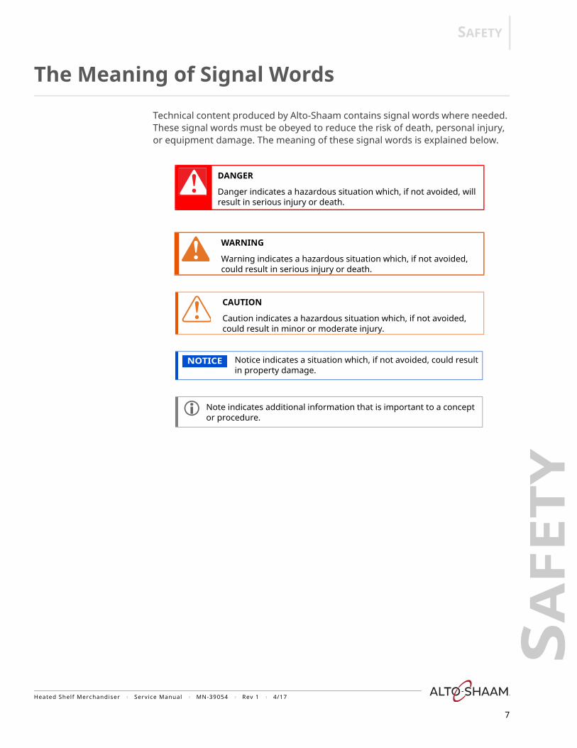
The Meaning of Signal Words
Technical content produced by Alto-Shaam contains signal words where needed. These signal words must be obeyed to reduce the risk of death, personal injury, or equipment damage. The meaning of these signal words is explained below.
DANGER
Danger indicates a hazardous situation which, if not avoided, will result in serious injury or death.
WARNING
Warning indicates a hazardous situation which, if not avoided, could result in serious injury or death.
CAUTION
Caution indicates a hazardous situation which, if not avoided, could result in minor or moderate injury.
NOTICE Notice indicates a situation which, if not avoided, could result in property damage.
Note indicates additional information that is important to a concept or procedure.
SAFETY
Safety Precautions
Before you begin Read and understand all instructions in this manual.
▪ The merchandiser is intended to hold pre-packaged food for human consumption. No other use for this merchandiser is authorized by the manufacturer or its agents and is therefore considered dangerous.
▪ The merchandiser is intended for use in commercial establishments where all operators are familiar with the purpose, limitations, and associated hazards of this merchandiser. Operating instructions and warnings must be read and understood by all operators and users. Alto-Shaam recommends regular staff training to avoid the risk of accident or damage to the merchandiser. Operators must also receive regular safety instructions.
Usage precautions Follow these precautions when using the appliance:
▪ To prevent serious injury, death or property damage, the merchandiser should be inspected and serviced at least every twelve (12) months by an authorized service partner or trained technician.
▪ Only allow an authorized service partner or trained technician to service or to repair the merchandiser. Installation or repairs that are not performed by an authorized service partner or trained technician, or the use of non-factory authorized parts will void the warranty and relieve Alto-Shaam of all liability.
▪ When working on this merchandiser, observe precautions in the manual, on tags, on labels attached to or shipped with the merchandiser, and other safety precautions that may apply.
▪ If the merchandiser is installed on casters, freedom of movement of the merchandiser must be restricted so that utility connections (electricity) cannot be damaged when the merchandiser is moved before moving. If the merchandiser is moved, make sure all utility connections are disconnected. When returning the merchandiser to its original position, make sure that retention devices and utility connections are connected.
▪ Only use the merchandiser when it is stationary. Unload the merchandiser before moving it. Merchandises on casters can tip over when being moved over an uneven floor or threshold and cause serious injury. Always apply caster brakes on the mobile merchandiser when it is not being moved.
Heated Shelf Merchandiser ? Service Manual ? MN-39054 ? Rev 1 ? 4/17
8
SAFETY
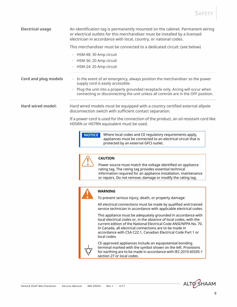
Electrical usage An identification tag is permanently mounted on the cabinet. Permanent wiring or electrical outlets for this merchandiser must be installed by a licensed electrician in accordance with local, country, or national codes.
This merchandiser must be connected to a dedicated circuit: (see below)
▪ HSM-48: 30 Amp circuit▪ HSM-36: 20 Amp circuit▪ HSM-24: 20 Amp circuit
Cord and plug models ▪ In the event of an emergency, always position the merchandiser so the power supply cord is easily accessible.
▪ Plug the unit into a properly grounded receptacle only. Arcing will occur when connecting or disconnecting the unit unless all controls are in the OFF position.
Hard wired model: Hard wired models must be equipped with a country certified external allpole disconnection switch with sufficient contact separation.
If a power cord is used for the connection of the product, an oil resistant cord like H05RN or H07RN equivalent must be used.
NOTICE Where local codes and CE regulatory requirements apply, appliances must be connected to an electrical circuit that is protected by an external GFCI outlet.
CAUTION
Power source must match the voltage identified on appliance rating tag. The rating tag provides essential technical information required for an appliance installation, maintenance or repairs. Do not remove, damage or modify the rating tag.
WARNING
To prevent serious injury, death, or property damage:
All electrical connections must be made by qualified and trained service technician in accordance with applicable electrical codes.
This appliance must be adequately grounded in accordance with local electrical codes or, in the absence of local codes, with the current edition of the National Electrical Code ANSI/NFPA No. 70. In Canada, all electrical connections are to be made in accordance with CSA C22.1, Canadian Electrical Code Part 1 or local codes.
CE-approved appliances include an equipotential-bonding terminal marked with the symbol shown on the left. Provisions for earthing are to be made in accordance with IEC:2010 60335-1 section 27 or local codes.
Heated Shelf Merchandiser ? Service Manual ? MN-39054 ? Rev 1 ? 4/17
9
SAFETY
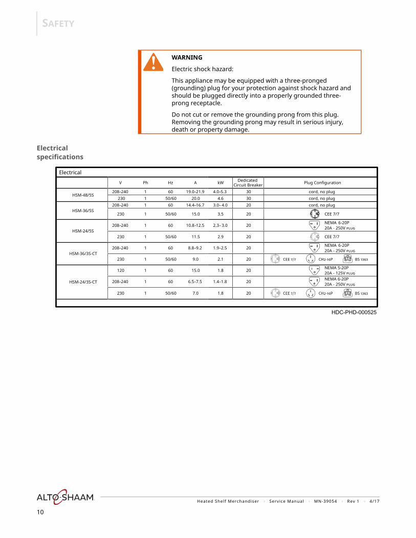
Electrical specifications
WARNING
Electric shock hazard:
This appliance may be equipped with a three-pronged (grounding) plug for your protection against shock hazard and should be plugged directly into a properly grounded three-prong receptacle.
Do not cut or remove the grounding prong from this plug. Removing the grounding prong may result in serious injury, death or property damage.
Electrical
V Ph Hz A kW
HSM-48/5S
HSM-36/5S
HSM-24/5S
HSM-36/3S-CT
HSM-24/3S-CT
1 60208– 240 19.0– 21.9 4.0– 5.3 230 1 50/60 20.0 4.6
1208– 240 60 14.4– 16.7 3.0– 4.0
230 1 50/60 15.0 3.5
1208– 240 60 10.8– 12.5 2.3– 3.0
230 1 50/60 11.5 2.9
1 60208– 240 8.8– 9.2 1.9– 2.5
230 1 50/60 9.0 2.1
120 1 60 15.0 1.8
1208– 240 60 6.5– 7.5 1.4– 1.8
230 1 50/60 7.0 1.8
Dedicated Circuit Breaker
303020
20
20
20
20
20
20
20
20
Plug Configuration
cord, no plugcord, no plugcord, no plug
CEE 7/7
NEMA20A - 250V
CEE 7/7
NEMA20A - 250V
5-20P20A - 125V
6-20P20A - 250V
6-20P
6-20P
NEMA
NEMA
HDC-PHD-000525
Heated Shelf Merchandiser ? Service Manual ? MN-39054 ? Rev 1 ? 4/17
10
OPERATION
Heated Shelf Merchandiser ? Service Manual ? MN-39054 ? Rev 1 ? 4/17
11
PER
AT
ION
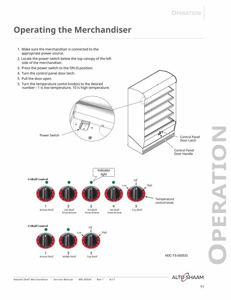
Operating the Merchandiser
Control PanelDoor Handle
Control PanelDoor Latch
1. Make sure the merchandiser is connected to theappropriate power source.
2. Locate the power switch below the top canopy of the leftside of the merchandiser.
3. Press the power switch to the ON (l) position.4. Turn the control panel door latch.5. Pull the door open.5. Turn the temperature contol knob(s) to the desired
Power Switch
Indicatorlight
Temperaturecontrol knob
HDC-TS-000533
number-- 1 is low temperature, 10 is high temperature.
COMPONENTS
COM
PO
NEN
TS
12
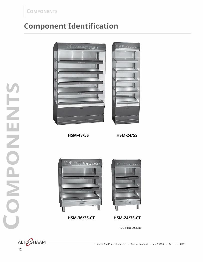
Component Identification
HDC-PHD-000538
HSM-48/5S HSM-24/5S
HSM-36/3S-CT HSM-24/3S-CT
Heated Shelf Merchandiser ? Service Manual ? MN-39054 ? Rev 1 ? 4/17
COMPONENTS
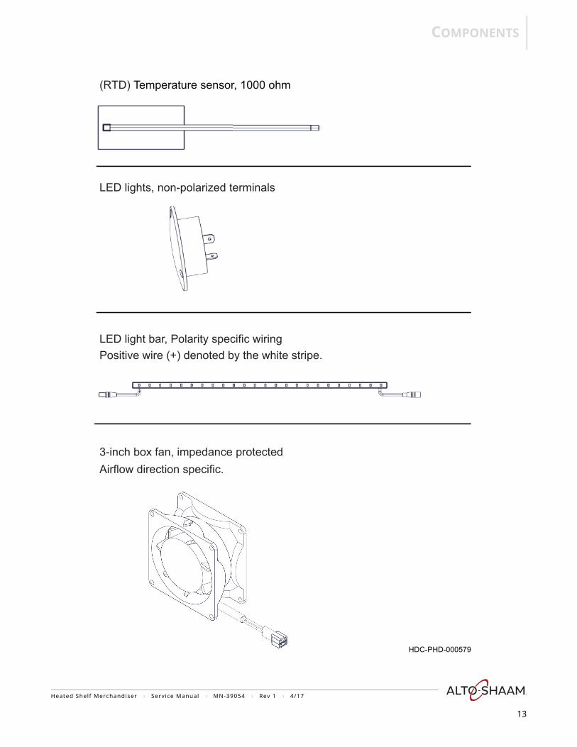
(RTD) Temperature sensor, 1000 ohm
LED lights, non-polarized terminals
LED light bar, Polarity specific wiringPositive wire (+) denoted by the white stripe.
3-inch box fan, impedance protectedAirflow direction specific.
HDC-PHD-000579
Heated Shelf Merchandiser ? Service Manual ? MN-39054 ? Rev 1 ? 4/17
13
COMPONENTS
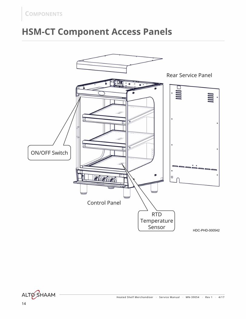
HSM-CT Component Access Panels
Rear Service Panel
Control Panel
ON/OFF Switch
RTDTemperature
SensorHDC-PHD-000542
Heated Shelf Merchandiser ? Service Manual ? MN-39054 ? Rev 1 ? 4/17
14
COMPONENTS
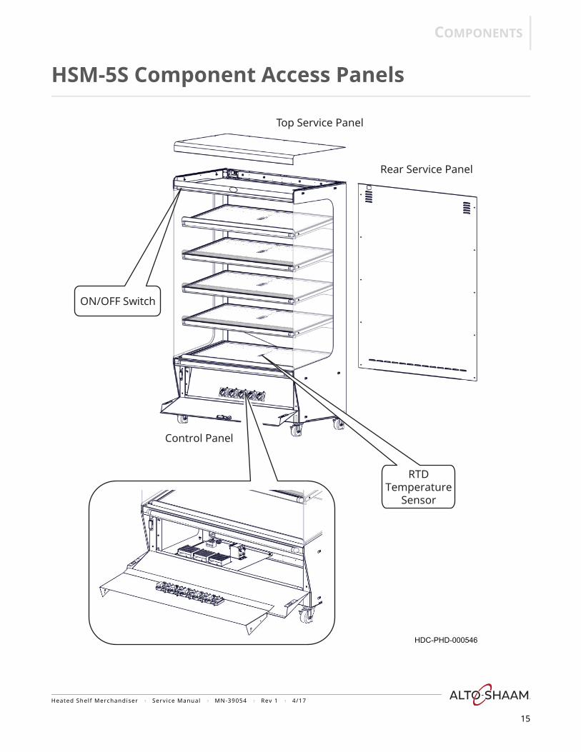
HSM-5S Component Access Panels
ON/OFF Switch
Control Panel
Top Service Panel
Rear Service Panel
HDC-PHD-000546
RTDTemperature
Sensor
Heated Shelf Merchandiser ? Service Manual ? MN-39054 ? Rev 1 ? 4/17
15
COMPONENTS
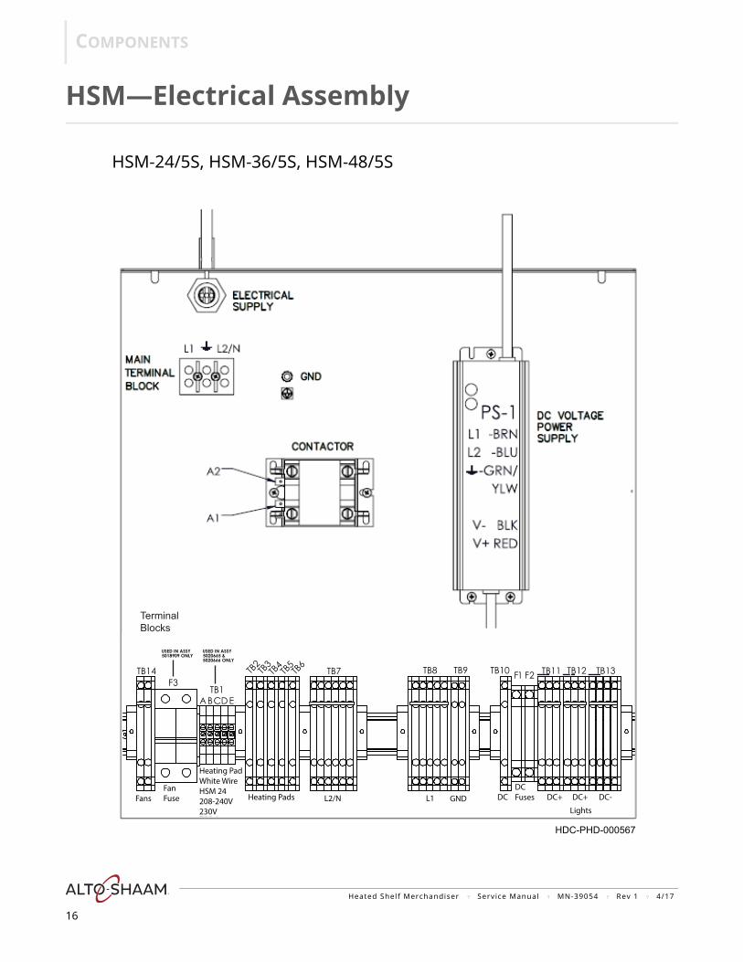
HSM—Electrical Assembly
Terminal Blocks
ABCDE
HDC-PHD-000567
HSM-24/5S, HSM-36/5S, HSM-48/5S
CD E
L2/NFansFanFuse
Heating PadWhite WireHSM 24208-240V230V
Heating Pads L1 GND DCDCFuses DC+ DC+ DC-
Lights
Heated Shelf Merchandiser ? Service Manual ? MN-39054 ? Rev 1 ? 4/17
16
COMPONENTS
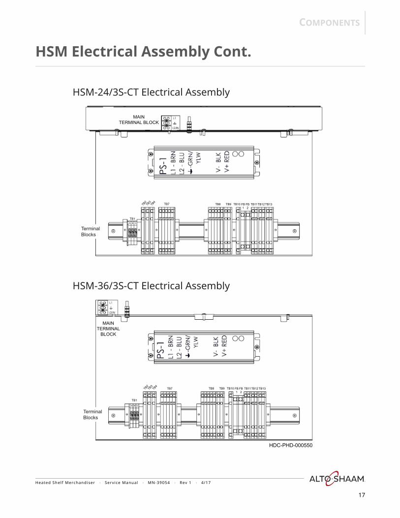
HSM Electrical Assembly Cont.
HSM-24/3S-CT Electrical Assembly
Terminal Blocks
Terminal Blocks
HSM-36/3S-CT Electrical Assembly
HDC-PHD-000550
MAINTERMINAL BLOCK
MAINTERMINAL
BLOCK
TB1
TB2TB3
TB4TB7 TB8 TB9 TB13TB12TB11TB10 FB
1FB2
TB1
TB2TB3
TB4 TB7 TB8 TB9 TB13TB12TB11TB10 FB1
FB2
A B C
A B C
Heated Shelf Merchandiser ? Service Manual ? MN-39054 ? Rev 1 ? 4/17
17

COMPONENTS
Temperature Controller
HDC-PHD-000571
GND
Indicatorlight
Temperaturecontrol knob
Heated Shelf Merchandiser ? Service Manual ? MN-39054 ? Rev 1 ? 4/17
18
COMPONENTS
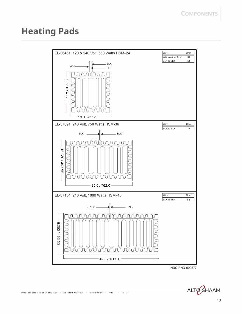
Heating Pads
WH
EL-36461 120 & 240 Volt, 550 Watts HSM-24
Blk Blk
Blk
EL-37091 240 Volt, 750 Watts HSM-36
Blk
Blk
EL-37134 240 Volt, 1000 Watts HSM-48
Blk
HDC-PHD-000577
BLK
BLK
BLKBLK
BLKBLK
Wire
WH to either BLKBLK to BLK
Ohm
52105
Wire
BLK to BLK
Ohm
77
Wire
BLK to BLK
Ohm
58
Heated Shelf Merchandiser ? Service Manual ? MN-39054 ? Rev 1 ? 4/17
19
THEORY
HEOR
Y
20
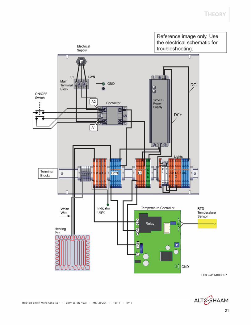
HSM-24/5S (208-240V, 230V)
Electrical power is supplied into the unit to the main terminal block, the contactor and the ON/OFF switch. When the ON/OFF switch is selected to the ON position, line voltage is supplied to the A1 and A2 terminals of the contactor. The contactor activates and supplies power to L1 and L2/N terminal blocks, the fans, and the 12 VDC power supply.
12 VDC is supplied to fuses FB1 and FB2 from the power supply. The DC+ and DC- terminal blocks are the connection points for the lights.
Line voltage is supplied to the L1, L2/N, and COM terminals of the temperature controller from the L1 and L2/N terminal blocks. The RTD temperature sensor provides a resistance signal into the temperature controller corresponding to surface temperature of the shelf it is mounted to. The temperature controller monitors the requested temperature from the temperature control knob setting and the shelf temperature from the RTD temperature sensor. When a call for heat is made, the temperature controller closes the NO contacts of the relay. L1 voltage is supplied to the terminal block and then to one of the black wires of the heating pad. The other black wire from the heating pad is connected to the L2/N terminal block. The white wire from the heating pad is connected to the terminal block with no other connection. The two coils in the heating pad are connected in series. The indicator light illuminates signaling the call for heat from the temperature controller.
When the shelf has reached the requested temperature, the temperature controller opens the NO contacts of the relay. L1 voltage is no longer supplied to the heating pad. The indicator light goes out.
Heated Shelf Merchandiser ? Service Manual ? MN-39054 ? Rev 1 ? 4/17
THEORY
A2
A1
Terminal Blocks
Relay
Reference image only. Use the electrical schematic for troubleshooting.
HDC-WD-000597
DC-
L1L2
/NC
OM
N.O
.
DC+
L1L2/N
Heated Shelf Merchandiser ? Service Manual ? MN-39054 ? Rev 1 ? 4/17
21

THEORY
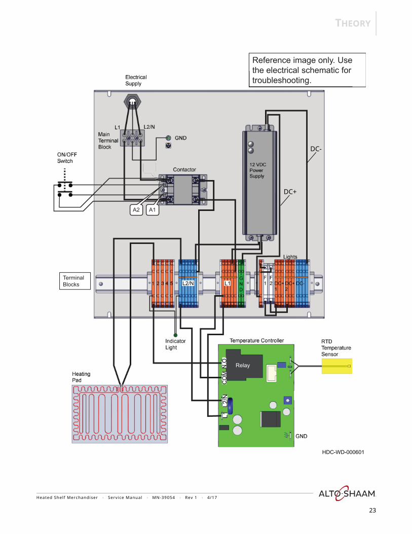
HSM-36/5S (208-240V, 230V)
Electrical power is supplied into the unit to the main terminal block, the contactor and the ON/OFF switch. When the ON/OFF switch is selected to the ON position, line voltage is supplied to the A1 and A2 terminals of the contactor. The contactor activates and supplies power to L1 and L2/N terminal blocks, the fans, and the 12 VDC power supply.
12 VDC is supplied to fuses FB1 and FB2 from the power supply. The DC+ and DC- terminal blocks are the connection points for the lights.
Line voltage is supplied to the L1, L2/N, and COM terminals of the temperature controller from the L1 and L2/N terminal blocks. The RTD temperature sensor provides a resistance signal into the temperature controller corresponding to surface temperature of the shelf it is mounted to. The temperature controller monitors the requested temperature from the temperature control knob setting and the shelf temperature from the RTD temperature sensor. When a call for heat is made, the temperature controller closes the NO contacts of the relay. L1 voltage is supplied to the terminal block and then to one of the black wires of the heating pad. The other black wire from the heating pad is connected to the L2/N terminal block. The indicator light illuminates signaling the call for heat from the temperature controller.
When the shelf has reached the requested temperature, the temperature controller opens the NO contacts of the relay. L1 voltage is no longer supplied to the heating pad. The indicator light goes out.
Heated Shelf Merchandiser ? Service Manual ? MN-39054 ? Rev 1 ? 4/17
22
THEORY
A2A2
Relay
A1
Terminal
Reference image only. Use the electrical schematic for troubleshooting.
Blocks
HDC-WD-000601
DC-
L1L2
/NC
OM
N.O
.
DC+
L1L2/N
A2
Heated Shelf Merchandiser ? Service Manual ? MN-39054 ? Rev 1 ? 4/17
23
THEORY
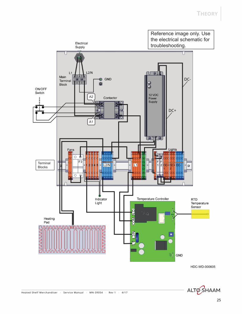
HSM-48/5S (208-240V, 230V)
Electrical power is supplied into the unit to the main terminal block, the contactor and the ON/OFF switch. When the ON/OFF switch is selected to the ON position, line voltage is supplied to the A1 and A2 terminals of the contactor. The contactor activates and supplies power to L1 and L2/N terminal blocks, the fans, and the 12 VDC power supply. The fan circuit has a fuse (F3) and additional terminal blocks.
12 VDC is supplied to fuses FB1 and FB2 from the power supply. The DC+ and DC- terminal blocks are the connection points for the lights.
Line voltage is supplied to the L1, L2/N, and COM terminals of the temperature controller from the L1 and L2/N terminal blocks. The RTD temperature sensor provides a resistance signal into the temperature controller corresponding to surface temperature of the shelf it is mounted to. The temperature controller monitors the requested temperature from the temperature control knob setting and the shelf temperature from the RTD temperature sensor. When a call for heat is made, the temperature controller closes the NO contacts of the relay. L1 voltage is supplied to the terminal block and then to one of the black wires of the heating pad. The other black wire from the heating pad is connected to the L2/N terminal block. The indicator light illuminates signaling the call for heat from the temperature controller.
When the shelf has reached the requested temperature, the temperature controller opens the NO contacts of the relay. L1 voltage is no longer supplied to the heating pad. The indicator light goes out.
Heated Shelf Merchandiser ? Service Manual ? MN-39054 ? Rev 1 ? 4/17
24
THEORY
ReRelalayyReRRReeelalllaaayyyy
A2
A1
Terminal
Reference image only. Use the electrical schematic for troubleshooting.
Blocks
HDC-WD-000605
DC-
L1L2
/NC
OM
N.O
.
DC+
L1L2/N
Heated Shelf Merchandiser ? Service Manual ? MN-39054 ? Rev 1 ? 4/17
25
THEORY
HSM-24/3S-CT (120V)
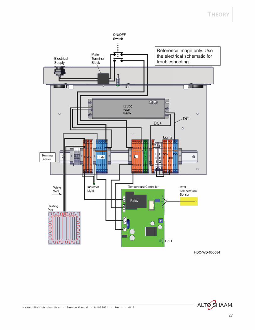
Electrical power is supplied into the unit and connected at the main terminal block. When the ON/OFF switch is selected to the ON position, line voltage is supplied to the L1 terminal block, the fans, and the 12 VDC power supply. The L2/N terminal block acts as neutral.
12 VDC is supplied to fuses FB1 and FB2 from the power supply. The DC+ and DC- terminal blocks are the connection points for the lights.
Line voltage (L1) is supplied to the L1 and COM terminal of the temperature controller from the L1 terminal block. The RTD temperature sensor provides a resistance signal to the temperature controller corresponding to surface temperature of the shelf it is mounted to.
The temperature controller monitors the requested temperature from the temperature control knob setting and the shelf temperature from the RTD temperature sensor. When a call for heat is made, the temperature controller closes the NO contacts of the relay. L1 voltage is supplied to the terminal block and then to the two coils within the heating pad. The white wire from the heating pad is connected to the L2/N terminal block. The two coils in the heating pad are connected in parallel. The indicator light illuminates signaling the call for heat from the temperature controller.
When the shelf has reached the requested temperature, the temperature controller opens the NO contacts of the relay. L1 voltage is no longer supplied to the heating pad. The indicator light goes out.
Heated Shelf Merchandiser ? Service Manual ? MN-39054 ? Rev 1 ? 4/17
26
THEORY
Relay
Terminal Blocks
Reference image only. Use the electrical schematic for troubleshooting.
HDC-WD-000584
L1L2
/NC
OM
N.O
.DC+
DC-
L1L2/N
Heated Shelf Merchandiser ? Service Manual ? MN-39054 ? Rev 1 ? 4/17
27
THEORY
HSM-24/3S-CT (208-240V, 230V)
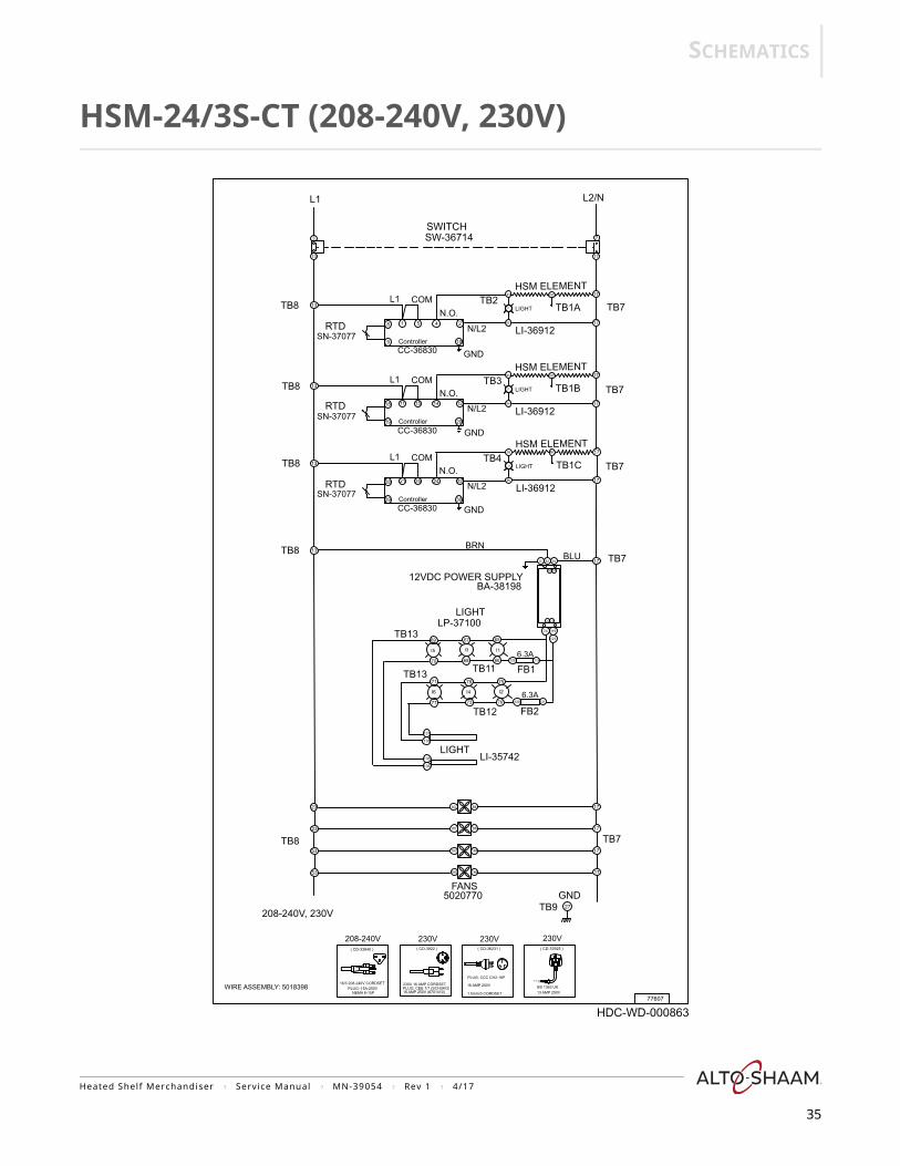
Electrical power is supplied into the unit and connected at the main terminal block. When the ON/OFF switch is selected to the ON position, line voltage is supplied to the L1 and L2/N terminal blocks, the fans, and the 12 VDC power supply.
12 VDC is supplied to fuses FB1 and FB2 from the power supply. The DC+ and DC- terminal blocks are the connection points for the lights.
Line voltage is supplied to the L1, L2/N, and COM terminals of the temperature controller from the L1 and L2/N terminal blocks. The RTD temperature sensor provides a resistance signal into the temperature controller corresponding to surface temperature of the shelf it is mounted to. The temperature controller monitors the requested temperature from the temperature control knob setting and the shelf temperature from the RTD temperature sensor. When a call for heat is made, the temperature controller closes the NO contacts of the relay. L1 voltage is supplied to the terminal block and then to one of the black wires of the heating pad. The other black wire from the heating pad is connected to the L2/N terminal block. The white wire from the heating pad is connected to the terminal block with no other connection. The two coils in the heating pad are connected in series. The indicator light illuminates signaling the call for heat from the temperature controller.
When the shelf has reached the requested temperature, the temperature controller opens the NO contacts of the relay. L1 voltage is no longer supplied to the heating pad. The indicator light goes out.
Heated Shelf Merchandiser ? Service Manual ? MN-39054 ? Rev 1 ? 4/17
28

THEORY
Relay
Terminal Blocks
Reference image only. Use the electrical schematic for troubleshooting.
HDC-WD-588
DC-L1
L2/N
CO
MN
.O.
DC+
L1L2/N
Heated Shelf Merchandiser ? Service Manual ? MN-39054 ? Rev 1 ? 4/17
29
THEORY
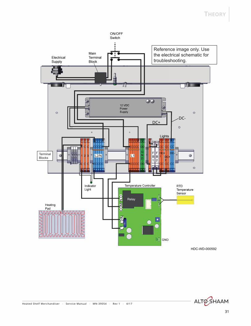
HSM-36/3S-CT (208-240V, 230V)
Electrical power is supplied into the unit and connected at the main terminal block. When the ON/OFF switch is selected to the ON position, line voltage is supplied to the L1 and L2/N terminal blocks, the fans, and the 12 VDC power supply.
12 VDC is supplied to fuses FB1 and FB2 from the power supply. The DC+ and DC- terminal blocks are the connection points for the lights.
Line voltage is supplied to the L1, L2/N, and COM terminals of the temperature controller from the L1 and L2/N terminal blocks. The RTD temperature sensor provides a resistance signal into the temperature controller corresponding to surface temperature of the shelf it is mounted to. The temperature controller monitors the requested temperature from the temperature control knob setting and the shelf temperature from the RTD temperature sensor. When a call for heat is made, the temperature controller closes the NO contacts of the relay. L1 voltage is supplied to the terminal block and then to one of the black wires of the heating pad. The other black wire from the heating pad is connected to the L2/N terminal block. The indicator light illuminates signaling the call for heat from the temperature controller.
When the shelf has reached the requested temperature, the temperature controller opens the NO contacts of the relay. L1 voltage is no longer supplied to the heating pad. The indicator light goes out.
Heated Shelf Merchandiser ? Service Manual ? MN-39054 ? Rev 1 ? 4/17
30
THEORY
Relay
Terminal Blocks
Reference image only. Use the electrical schematic for troubleshooting.
HDC-WD-000592
DC-L1
L2/N
CO
MN
.O.
DC+
L1L2/N
Heated Shelf Merchandiser ? Service Manual ? MN-39054 ? Rev 1 ? 4/17
31
SCHEMATICS
SCHEM
AT
ICS
32
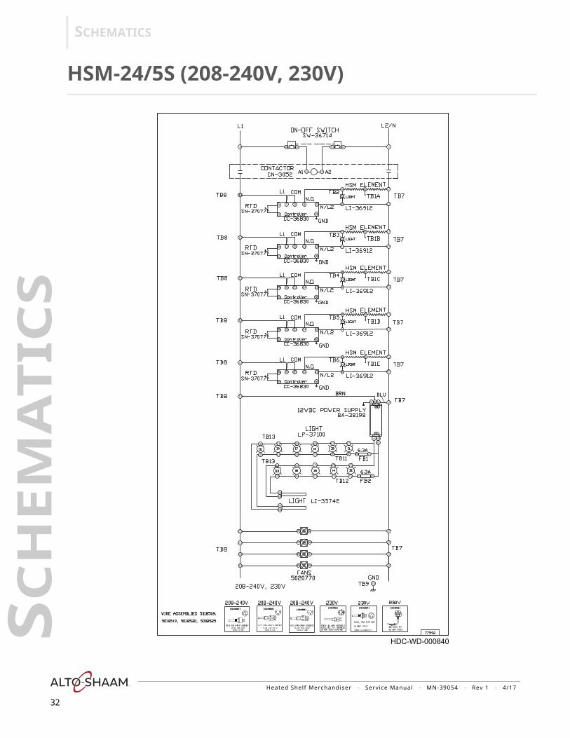
HSM-24/5S (208-240V, 230V)
( CD-33840 )( CD-33840 ) ( CD-36231 )( CD-36231 )( CD-3922 )( CD-3922 ) ( CD-33925 )( CD-33925 )( CD-3588 )( CD-3588 )( CD-34207 )( CD-34207 )
HDC-WD-000840
A1A1 A2A2
6.3A6.3A
6.3A6.3A
12VDC12VDC
BRNBRN BLUBLU
50207705020770
Heated Shelf Merchandiser ? Service Manual ? MN-39054 ? Rev 1 ? 4/17
SCHEMATICS
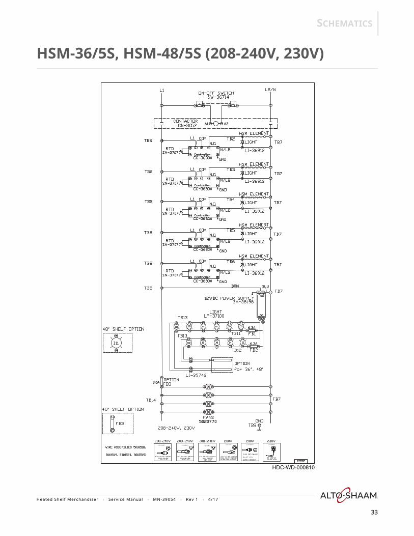
HSM-36/5S, HSM-48/5S (208-240V, 230V)
( CD-33840 ) ( CD-36231 )( CD-3922 ) ( CD-33925 )( CD-3588 )( CD-34207 )
HDC-WD-000810
BRNBRN
12VDC12VDC
6.3A6.3A
6.3A6.3A
3.0A3.0A
A1A1 A2A2
50207705020770
BLUBLU
Heated Shelf Merchandiser ? Service Manual ? MN-39054 ? Rev 1 ? 4/17
33
SCHEMATICS
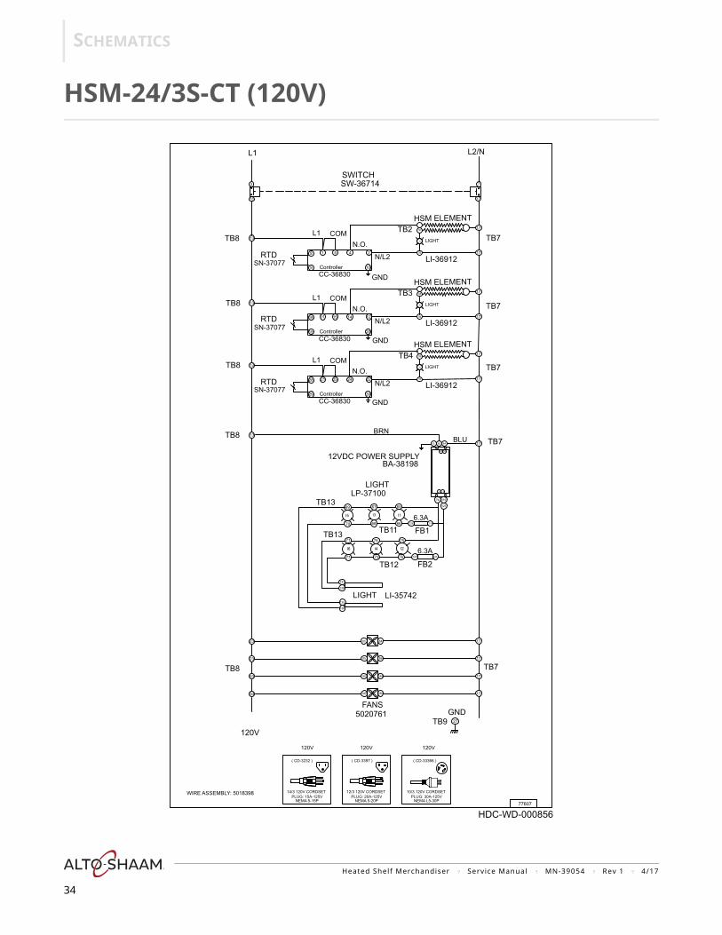
HSM-24/3S-CT (120V)
HDC-WD-000856
L1 L2/N
SW-36714 SWITCH
TB8
TB8
TB8
GND
N/L2
HSM ELEMENT
SN-37077
SN-37077
SN-37077
TB7
RTD
RTD
RTDController
CC-36830
CC-36830
TB7
TB7
GND
COML1N.O.
N/L2
HSM ELEMENT
TB2 LIGHT
LI-36912
BA-3819812VDC POWER SUPPLY
HSM ELEMENT
LP-37100 LIGHT
TB8
LIGHT
LI-36912
LIGHT
LI-36912
WIRE ASSEMBLY: 5018398
GND
77607
120V
5020761 TB9
TB13
FANS
TB7
TB7
TB8
FB1
FB2
LI-35742
TB12
TB11 TB13
LIGHT
10/3 120V CORDSET PLUG: 30A-125V
NEMA L5-30P
14/3 120V CORDSET PLUG: 15A-125V
NEMA 5-15P
12/3 120V CORDSET PLUG: 20A-125V
NEMA 5-20P
120V 120V 120V
( CD-33366 )( CD-3232 ) ( CD-3397 )
27
17
17
17
85 86
183
185
184
186
1783 84
137
138
135
136
23
23
53
53
I4I6
68
7377
7871
13
I5 I3
2225 2421
30
28
29
GND
COML1N.O.
N.O.
N/L2
6769
70
ControllerCC-36830
13
13
1215 1411
20
18
19
25 41
10
8
9
COML1
13
3
13 17
7
92
91
17
17
I1
94
93
17
17
I2
96
95
17
17
I3
TB4
TB3
I1
I2
126
65
119
129 121
66
76
75
Controller
1762 64G
B R
BR BU
11974
121
BRNBLU
6.3A
6.3A
Heated Shelf Merchandiser ? Service Manual ? MN-39054 ? Rev 1 ? 4/17
34
SCHEMATICS
HSM-24/3S-CT (208-240V, 230V)
GRN BWNBLU
L1 L2/N
SW-36714 SWITCH
TB7 TB8
TB8
TB8 TB7
TB7
WIRE ASSEMBLY: 5018398
208-240V, 230V
5020770 FANS
TB7
TB7 TB8
TB8
GND
230V 230V 230V208-240V
TB9
16/3 208-240V CORDSET PLUG: 15A-250V
NEMA 6-15P
230V 16 AMP CORDSET
16 AMP 250V (#701410)PLUG, CEE 7/7 (SCHUKO)
( CD-33840 ) ( CD-36231 )( CD-3922 ) ( CD-33925 )
PLUG, CCC CH2-16P
16 AMP 250V
1.5mm/3 CORDSET 13 AMP 250VBS 1363 UK
17
27
17
17
17
83 84
85 86
183
185
184
186
FB1
FB2
LP-37100
LI-35742
TB12
TB11 TB13
TB13
LIGHT
LIGHT
BA-3819812VDC POWER SUPPLY
I2I4I6
137
138
129 121
135
136
7377 76
7871 75
N.O.
N/L2
HSM ELEMENT
HSM ELEMENTTB4
TB3
LI-36912
LIGHT TB1B
LI-36912
LIGHT TB1C
GND
N.O.
N/L2
HSM ELEMENT
ControllerCC-36830
TB2
LI-36912
LIGHT TB1A
GND
COML1
COML1
N/L2
CC-36830
1215 1411
20
18
19
N.O.
92 17
17
I1
91 NC
94 17
17
I1
93 NC
Controller
25 41
10
8
9
17
7
13
13
13
COML1
3
13
SN-37077
SN-37077
SN-37077RTD
RTD
RTD
ControllerCC-36830
13
2225 2421
30
28
29
GND
96 17
17
I1
95 NC
1762 64G
BR BU
I1
B R
126
65
11974
119
121
66
I5 I3
6769
6870
23
23
53
53
77607
HDC-WD-000863
BRNBLU
6.3A
6.3A
Heated Shelf Merchandiser ? Service Manual ? MN-39054 ? Rev 1 ? 4/17
35

SCHEMATICS
HSM-36/3S-CT (208-240V, 230V)
13
L1 L2/N
SW-36714 SWITCH
TB8
TB8 TB7
TB7
GND
BA-3819812VDC POWER SUPPLY
HSM ELEMENT
HSM ELEMENT
HSM ELEMENT
FB1
FB2
LP-37100
208-240V, 230V
5020770
LI-35742
TB12
TB11
TB9
TB13
TB13
FANS
LIGHT
LI-36912
LI-36912
LIGHT
LI-36912
LIGHT
LIGHT
WIRE ASSEMBLY: 5018398
77607
230V 230V 230V208-240V
TB7 TB8
PLUG, CCC CH2-16P
16 AMP 250V
1.5mm/3 CORDSET
16/3 208-240V CORDSET PLUG: 15A-250VNEMA 6-15P
230V 16 AMP CORDSET
16 AMP 250V (#701410)PLUG, CEE 7/7 (SCHUKO)
( CD-33840 ) ( CD-36231 )( CD-3922 ) ( CD-33925 )
13 AMP 250VBS 1363 UK
GRN BWNBLU
23
23
53
53
83 84
85 86
183
185
184
186
17
27
17
17
17
I2I4I6
137
138
129
135
136
7377 76
7871 75
I5 I1I3
126
6769 65
119
121
6870 66
11974
121
17 TB7 62 64G
B R
BR BU
96 17
I1
95
TB7
92 17
17
I1
94 17
I1
93
91
17
73
13
18
9
L1
SN-37077RTD
13
1118
19
L1
SN-37077RTD
ControllerCC-36830
13
2128
29
L1
SN-37077
TB8
RTDController
TB8
CC-36830 GND
GND
COMN.O.
N.O.
N/L2
N/L2
N/L2
TB4
TB3
TB2 LIGHT
GND
COM
COM
N.O.
ControllerCC-36830
2225 24
30
1215 14
20
17
25 4
10
17
13
HDC-WD-000867
BRN BLU
6.3A
6.3A
Heated Shelf Merchandiser ? Service Manual ? MN-39054 ? Rev 1 ? 4/17
36
TROUBLESHOOTING
Heated Shelf Merchandiser ? Service Manual ? MN-39054 ? Rev 1 ? 4/17
37
RO
UB
LESH
OO
TIN
G
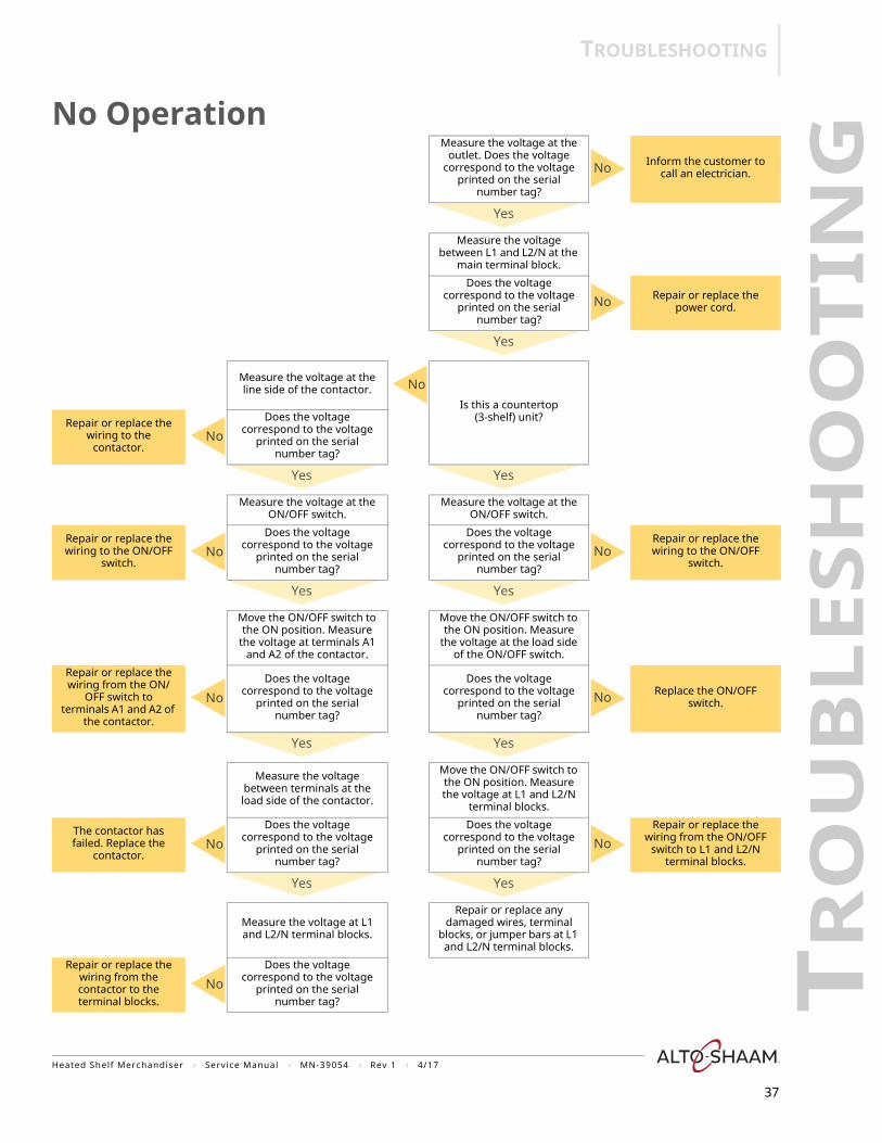
No OperationMeasure the voltage at the
outlet. Does the voltage correspond to the voltage
printed on the serial number tag?
No Inform the customer to call an electrician.
Yes
Measure the voltage between L1 and L2/N at the
main terminal block.
Does the voltage correspond to the voltage
printed on the serial number tag?
No Repair or replace the power cord.
Yes
Measure the voltage at the line side of the contactor. No
Is this a countertop (3-shelf) unit?Repair or replace the
wiring to the contactor.
NoDoes the voltage
correspond to the voltage printed on the serial
number tag?
Yes Yes
Measure the voltage at the ON/OFF switch.
Measure the voltage at the ON/OFF switch.
Repair or replace the wiring to the ON/OFF
switch.No
Does the voltage correspond to the voltage
printed on the serial number tag?
Does the voltage correspond to the voltage
printed on the serial number tag?
NoRepair or replace the wiring to the ON/OFF
switch.
Yes Yes
Move the ON/OFF switch to the ON position. Measure
the voltage at terminals A1 and A2 of the contactor.
Move the ON/OFF switch to the ON position. Measure
the voltage at the load side of the ON/OFF switch.
Repair or replace the wiring from the ON/
OFF switch to terminals A1 and A2 of
the contactor.
NoDoes the voltage
correspond to the voltage printed on the serial
number tag?
Does the voltage correspond to the voltage
printed on the serial number tag?
No Replace the ON/OFF switch.
Yes Yes
Measure the voltage between terminals at the load side of the contactor.
Move the ON/OFF switch to the ON position. Measure the voltage at L1 and L2/N
terminal blocks.
The contactor has failed. Replace the
contactor.No
Does the voltage correspond to the voltage
printed on the serial number tag?
Does the voltage correspond to the voltage
printed on the serial number tag?
NoRepair or replace the
wiring from the ON/OFF switch to L1 and L2/N
terminal blocks.
Yes Yes
Measure the voltage at L1 and L2/N terminal blocks.
Repair or replace any damaged wires, terminal
blocks, or jumper bars at L1 and L2/N terminal blocks.
Repair or replace the wiring from the contactor to the terminal blocks.
NoDoes the voltage
correspond to the voltage printed on the serial
number tag?
TROUBLESHOOTING
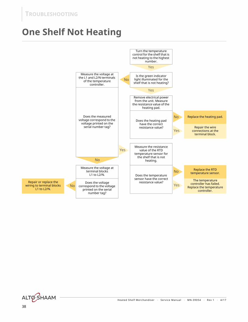
One Shelf Not Heating
Turn the temperature control for the shelf that is not heating to the highest
number.
Yes
Measure the voltage at the L1 and L2/N terminals
of the temperature controller.
NoIs the green indicator
light illuminated for the shelf that is not heating?
Does the measured voltage correspond to the
voltage printed on the serial number tag?
Yes
Remove electrical power from the unit. Measure
the resistance value of the heating pad.
Does the heating pad have the correct resistance value?
No Replace the heating pad.
YesRepair the wire
connections at the terminal block.
YesMeasure the resistance
value of the RTD temperature sensor for
the shelf that is not heating.No
Measure the voltage at terminal blocks
L1 to L2/N. Does the temperature sensor have the correct
resistance value?
No Replace the RTD temperature sensor.
Repair or replace the wiring to terminal blocks
L1 to L2/N.No
Does the voltage correspond to the voltage
printed on the serial number tag?
YesThe temperature
controller has failed. Replace the temperature
controller.
Heated Shelf Merchandiser ? Service Manual ? MN-39054 ? Rev 1 ? 4/17
38
TROUBLESHOOTING
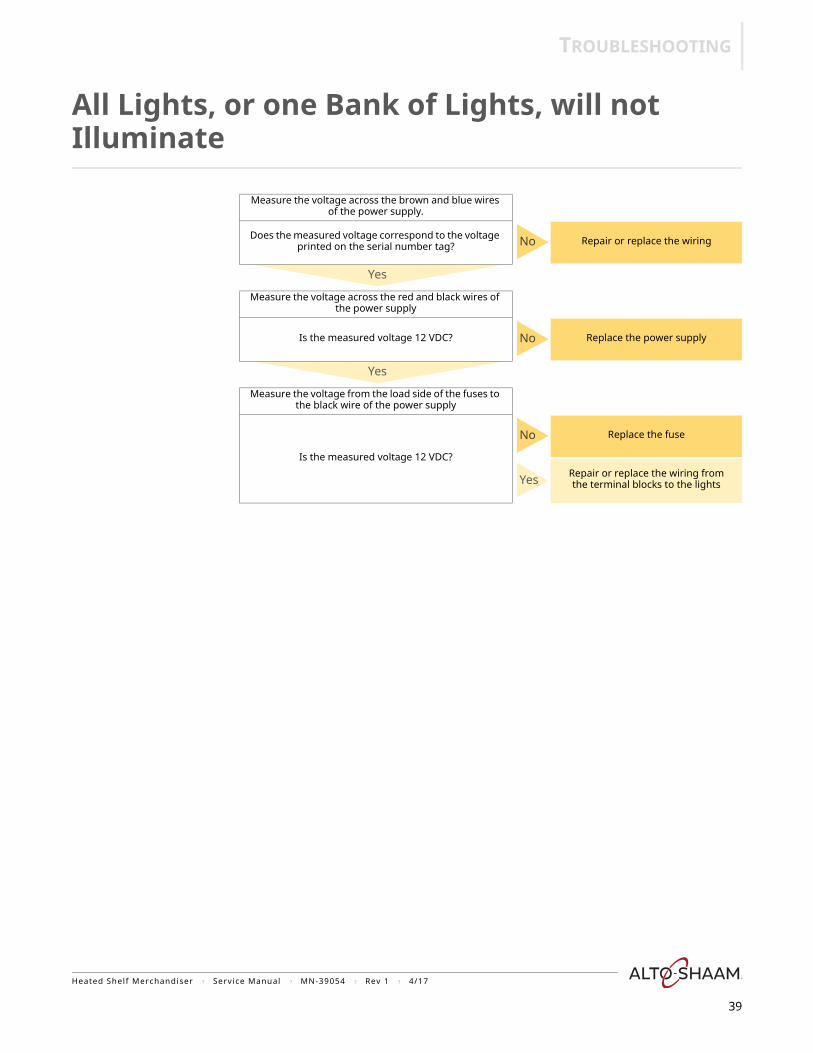
All Lights, or one Bank of Lights, will not Illuminate
Measure the voltage across the brown and blue wires of the power supply.
Does the measured voltage correspond to the voltage printed on the serial number tag? No Repair or replace the wiring
Yes
Measure the voltage across the red and black wires of the power supply
Is the measured voltage 12 VDC? No Replace the power supply
Yes
Measure the voltage from the load side of the fuses to the black wire of the power supply
Is the measured voltage 12 VDC?
No Replace the fuse
Yes Repair or replace the wiring from the terminal blocks to the lights
Heated Shelf Merchandiser ? Service Manual ? MN-39054 ? Rev 1 ? 4/17
39
TROUBLESHOOTING
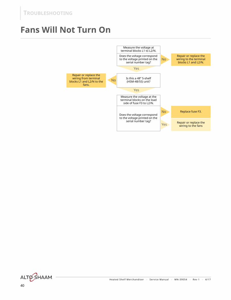
Fans Will Not Turn On
Measure the voltage at terminal blocks L1 to L2/N.
Does the voltage correspond to the voltage printed on the
serial number tag?No
Repair or replace the wiring to the terminal
blocks L1 and L2/N.
Yes
Repair or replace the wiring from terminal
blocks L1 and L2/N to the fans.
No Is this a 48” 5-shelf (HSM-48/5S) unit?
Yes
Measure the voltage at the terminal blocks on the load
side of fuse F3 to L2/N.
Does the voltage correspond to the voltage printed on the
serial number tag?
No Replace fuse F3.
Yes Repair or replace the wiring to the fans
Heated Shelf Merchandiser ? Service Manual ? MN-39054 ? Rev 1 ? 4/17
40
ASSEMBLY/DISASSEMBLY
Heated Shelf Merchandiser ? Service Manual ? MN-39054 ? Rev 1 ? 4/17
41
ASS
EMB
LY/D
ISA
SSEM
BLY
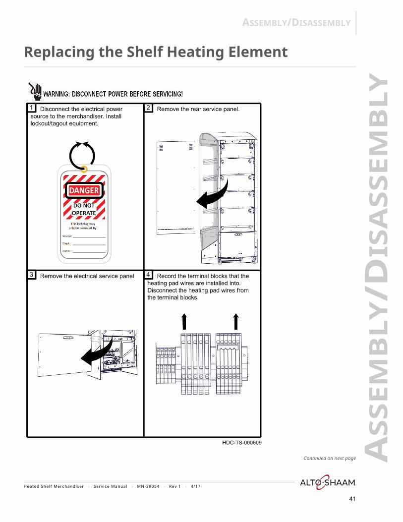
Replacing the Shelf Heating Element
Continued on next page
Disconnect the electrical power 1 2
3 4
source to the merchandiser. Installlockout/tagout equipment.
Remove the rear service panel.
Remove the electrical service panel Record the terminal blocks that the heating pad wires are installed into. Disconnect the heating pad wires from the terminal blocks.
HDC-TS-000609
ASSEMBLY/DISASSEMBLY
Continued from previous page
Continued on next page
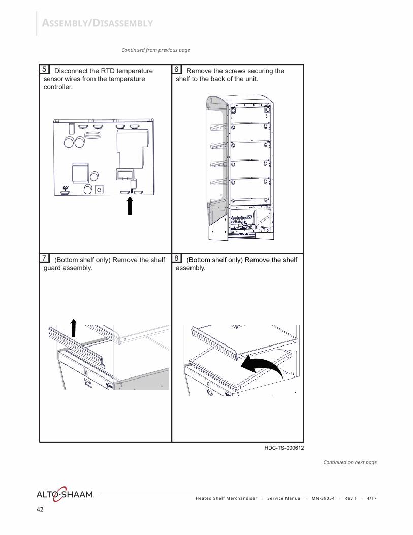
guard assembly.(Bottom shelf only) Remove the shelf
Remove the screws securing the shelf to the back of the unit.
Disconnect the RTD temperature 5 6
7
sensor wires from the temperature controller.
8 assembly.
(Bottom shelf only) Remove the shelf
HDC-TS-000612
Heated Shelf Merchandiser ? Service Manual ? MN-39054 ? Rev 1 ? 4/17
42

ASSEMBLY/DISASSEMBLY
Continued from previous page
Continued on next page
Remove the screws securing the shelf guard. Remove the shelf guard. Remove the screws from the sides of the shelf.
Remove the shelf from the unit.9 Remove the screws securing the shelf to the support.
10
11
HDC-TS-000656
Heated Shelf Merchandiser ? Service Manual ? MN-39054 ? Rev 1 ? 4/17
43
ASSEMBLY/DISASSEMBLY
Continued from previous page
Continued on next page
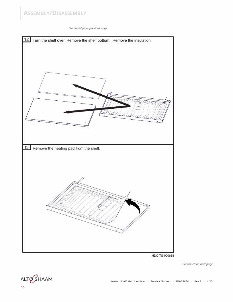
Remove the heating pad from the shelf.13
12 Turn the shelf over. Remove the shelf bottom. Remove the insulation.
HDC-TS-000658
Heated Shelf Merchandiser ? Service Manual ? MN-39054 ? Rev 1 ? 4/17
44
ASSEMBLY/DISASSEMBLY
Continued from previous page
Continued on next page
15
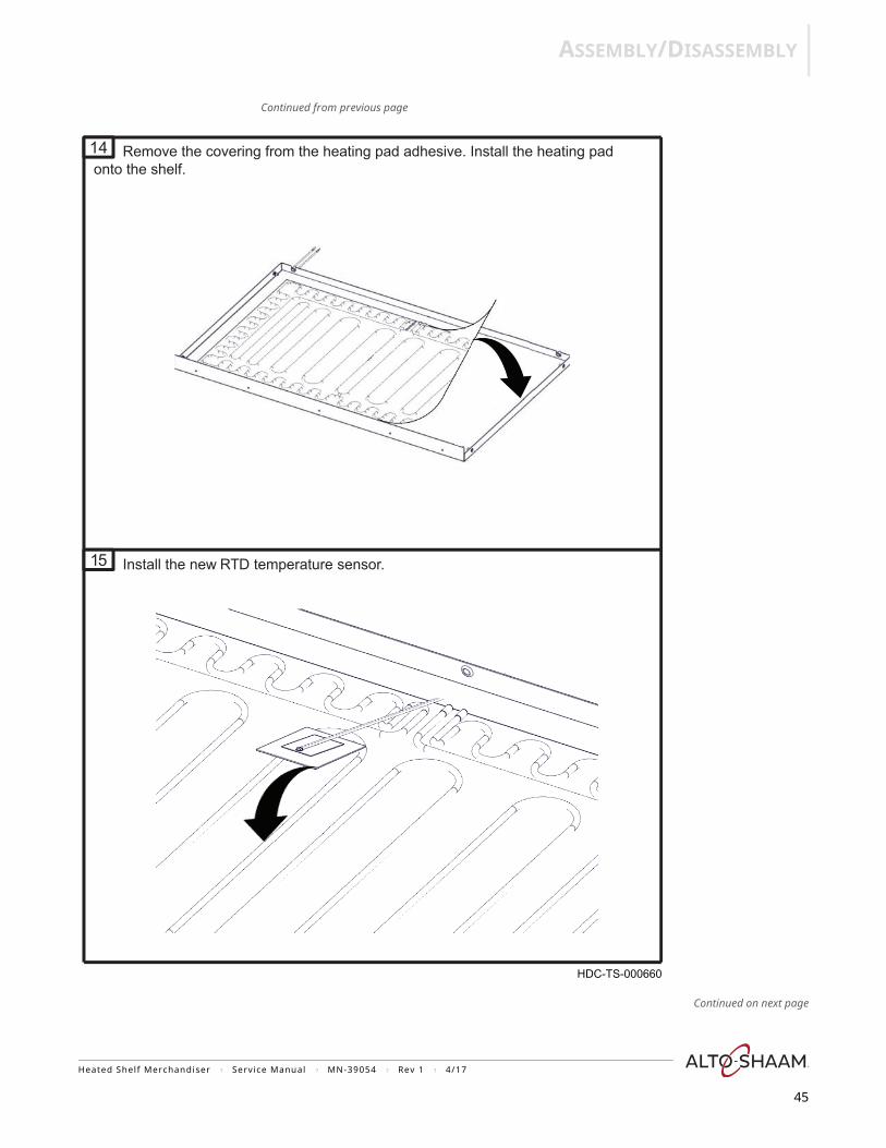
14 Remove the covering from the heating pad adhesive. Install the heating pad
Install the new RTD temperature sensor.
HDC-TS-000660
onto the shelf.
Heated Shelf Merchandiser ? Service Manual ? MN-39054 ? Rev 1 ? 4/17
45
ASSEMBLY/DISASSEMBLY
Continued from previous page
Continued on next page
17
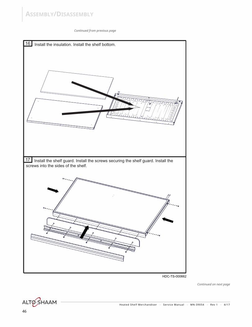
16 Install the insulation. Install the shelf bottom.
screws into the sides of the shelf.Install the shelf guard. Install the screws securing the shelf guard. Install the
HDC-TS-000662
Heated Shelf Merchandiser ? Service Manual ? MN-39054 ? Rev 1 ? 4/17
46
ASSEMBLY/DISASSEMBLY
Continued from previous page
Continued on next page
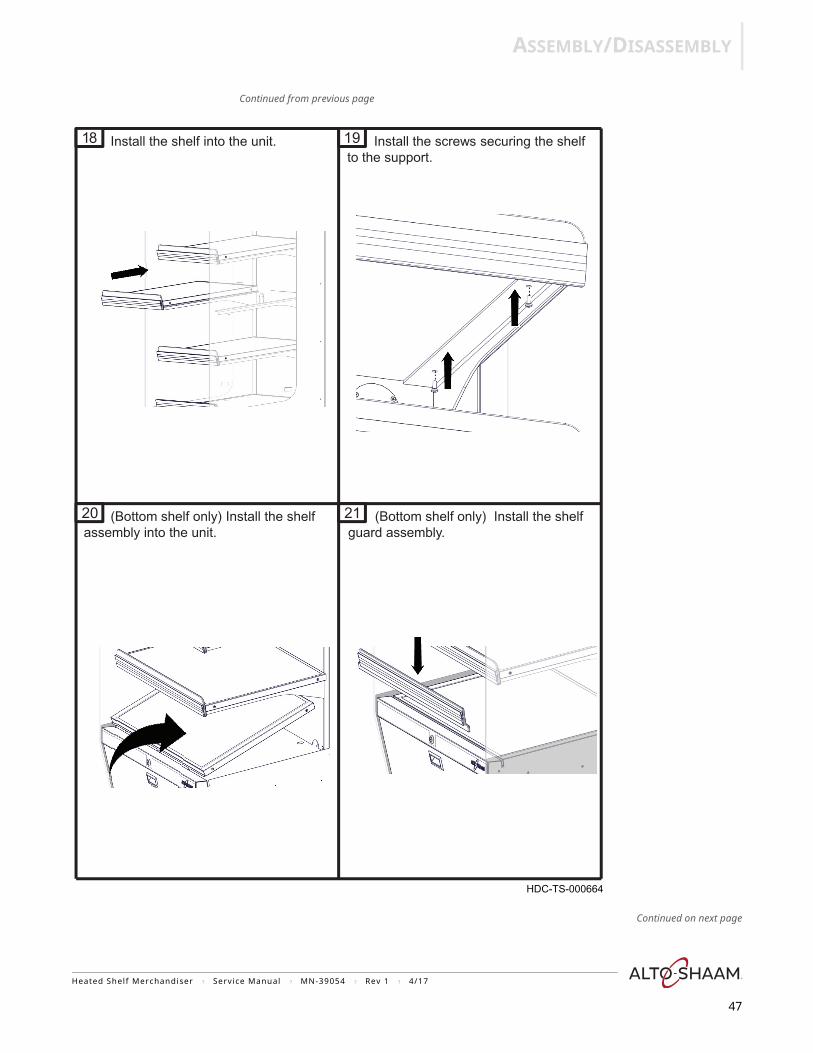
Install the shelf into the unit.to the support.
Install the screws securing the shelf 19
20
18
21(Bottom shelf only) Install the shelf assembly into the unit. guard assembly.
(Bottom shelf only) Install the shelf
HDC-TS-000664
Heated Shelf Merchandiser ? Service Manual ? MN-39054 ? Rev 1 ? 4/17
47
ASSEMBLY/DISASSEMBLY
Continued from previous page
Continued on next page
2524
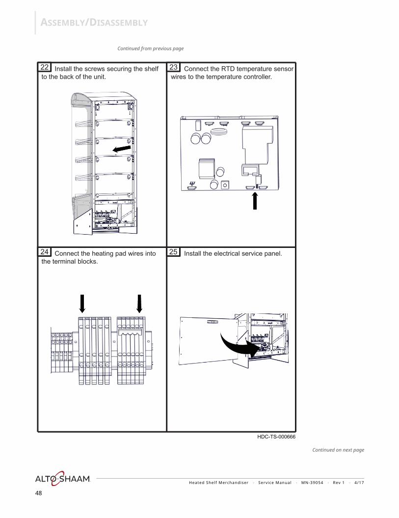
22 Install the screws securing the shelf 23to the back of the unit.
Connect the RTD temperature sensor wires to the temperature controller.
Connect the heating pad wires into the terminal blocks.
Install the electrical service panel.
HDC-TS-000666
Heated Shelf Merchandiser ? Service Manual ? MN-39054 ? Rev 1 ? 4/17
48
ASSEMBLY/DISASSEMBLY
Continued from previous page
2928
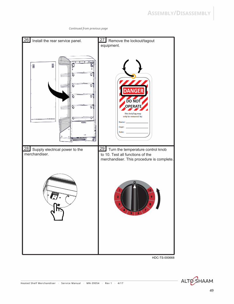
26 Install the rear service panel.equipment.27 Remove the lockout/tagout
Supply electrical power to the Turn the temperature control knob to 10. Test all functions of themerchandiser. This procedure is complete.
HDC-TS-000668
merchandiser.
Heated Shelf Merchandiser ? Service Manual ? MN-39054 ? Rev 1 ? 4/17
49
Heated Shelf Merchandiser


![Alcalini. ShellKLMNOP Li1s 2 [He] 2s Na1s 2 2s 2 2p 6 [Ne] 3s K1s 2 2s 2 2p 6 3s 2 3p 6 [Ar] 4s Rb1s 2 2s 2 2p 6 3s 2 3p 6 3d 10 4s 2 4p 6 [Kr] 5s Cs1s](https://img.dokumen.tips/doc/110x75/5542eb65497959361e8d0f1f/-alcalini-shellklmnop-li1s-2-he-2s-na1s-2-2s-2-2p-6-ne-3s-k1s-2-2s-2-2p-6-3s-2-3p-6-ar-4s-rb1s-2-2s-2-2p-6-3s-2-3p-6-3d-10-4s-2-4p-6-kr-5s-cs1s.jpg)