Embed Size (px)
Citation preview

HS-51/HS-51X Wireless Handheld Reader User Manual
P/N 84-100053 Rev A

Copyright and Disclaimer
Copyright ©2015Microscan Systems, Inc.Tel: +1.425.226.5700 / 800.762.1149 Fax: +1.425.226.8250
All rights reserved. The information contained herein is proprietary and is provided solely for the purpose of allowing customers to operate and/or service Microscan manufactured equipment and is not to be released, reproduced, or used for any other purpose without written permission of Microscan.
Throughout this manual, trademarked names might be used. We state herein that we are using the names to the benefit of the trademark owner, with no intention of infringement.
DisclaimerThe information and specifications described in this manual are subject to change without notice.
Latest Manual VersionFor the latest version of this manual, see the Download Center on our web site at: www.microscan.com.
Technical SupportFor technical support, e-mail: [email protected].
WarrantyFor current warranty information, see: www.microscan.com/warranty.
Microscan Systems, Inc.
United States Corporate Headquarters+1.425.226.5700 / 800.762.1149
United States Northeast Technology Center+1.603.598.8400 / 800.468.9503
European Headquarters+31.172.423360
Asia Pacific Headquarters+65.6846.1214
ii HS-51/HS-51X Wireless Handheld Reader User Manual
Introduction
Table of ContentsChapter 1 Quick Start
Check Hardware...................................................................................... 1-2Install the Battery..................................................................................... 1-3Charge the Reader .................................................................................. 1-4Wireless Interface.................................................................................... 1-5Install ESP ............................................................................................... 1-6Select Model ............................................................................................ 1-7Connect to the Reader ............................................................................ 1-8Configure the Reader .............................................................................. 1-9Save Changes in ESP ........................................................................... 1-10
Chapter 2 Using ESPApp Mode ................................................................................................ 2-2Tree Controls ........................................................................................... 2-3Menu Toolbar .......................................................................................... 2-4Send/Receive ....................................................................................... 2-14
Chapter 3 Basic OperationsPractice Targeting ................................................................................... 3-2Dual Optics .............................................................................................. 3-3Operational Feedback ............................................................................. 3-5
Chapter 4 CommunicationsCommunications by ESP......................................................................... 4-2Communications Overview...................................................................... 4-3Bluetooth ................................................................................................. 4-4Batch Mode ............................................................................................. 4-6Preamble ................................................................................................. 4-9Postamble.............................................................................................. 4-10Preamble and Postamble by ESP ......................................................... 4-11Keyboard Mapping ................................................................................ 4-12USB Keyboard Rate .............................................................................. 4-13Text Command Timeout ........................................................................ 4-14Other Communications Mode Commands ............................................ 4-15
Chapter 5 Read CycleRead Cycle by ESP ................................................................................. 5-2Trigger Active .......................................................................................... 5-3Default Continuous Event........................................................................ 5-4Maximum Decodes per Read .................................................................. 5-5Read Cycle Timeout ................................................................................ 5-6Ignore Duplicate Symbol Timeout ........................................................... 5-7Targeting Zone Tolerance ....................................................................... 5-8
HS-51/HS-51X Wireless Handheld Reader User Manual iii
Table of Contents
Morphological Preprocessing .................................................................. 5-9Camera Settings.................................................................................... 5-10
Chapter 6 SymbologiesSymbologies by ESP............................................................................... 6-2Data Matrix .............................................................................................. 6-3QR Code ................................................................................................. 6-4Aztec Code.............................................................................................. 6-5Code 39................................................................................................... 6-6Code 128................................................................................................. 6-7BC412 ..................................................................................................... 6-8Code 93................................................................................................... 6-9Codabar................................................................................................. 6-10Interleaved 2 of 5................................................................................... 6-11UPC....................................................................................................... 6-12Postal .................................................................................................... 6-13Pharmacode .......................................................................................... 6-14GS1 DataBar ......................................................................................... 6-16PDF417 ................................................................................................. 6-17MicroPDF417 ........................................................................................ 6-18Composite ............................................................................................. 6-19Symbology Identifier .............................................................................. 6-20
Chapter 7 I/O ParametersI/O Parameters by ESP ........................................................................... 7-2No Read Notification ............................................................................... 7-3Targeting ................................................................................................. 7-4Beep and Vibrate..................................................................................... 7-5Button Stay-Down Time .......................................................................... 7-6Button/Trigger Programming ................................................................... 7-7Data Validation ...................................................................................... 7-10
Chapter 8 Advanced OperationsContinuous Read..................................................................................... 8-2Mirroring .................................................................................................. 8-3Bluetooth Keyboard-to-Windows 7 Pairing.............................................. 8-4Bluetooth Keyboard-to-Table Pairing ...................................................... 8-8Bluetooth Keyboard-to-Mobile Phone Pairing ....................................... 8-11Reader Paging ...................................................................................... 8-13Bluetooth Out-of-Range Notification...................................................... 8-14Cell Phone Reading Enhancement ....................................................... 8-15
Chapter 9 TerminalTerminal View.......................................................................................... 9-2Find ......................................................................................................... 9-3Send ........................................................................................................ 9-4
iv HS-51/HS-51X Wireless Handheld Reader User Manual
Introduction
HS-51/HS-51X Wireless Handheld Reader User Manual v
Macros..................................................................................................... 9-5Terminal Right-Click Menu ...................................................................... 9-6Terminal Dropdown Menu ....................................................................... 9-7
Chapter 10 UtilitiesDifferences from Default ........................................................................ 10-2Firmware................................................................................................ 10-3Bluetooth ............................................................................................... 10-5Advanced............................................................................................... 10-6
AppendicesAppendix A General Specifications .........................................................A-2Appendix B Electrical Specifications .......................................................A-5Appendix C Configuration Symbols.........................................................A-6Appendix D Communications Protocol ..................................................A-18Appendix E ASCII Table........................................................................A-19Appendix F Maintenance.......................................................................A-20Appendix G Glossary of Terms .............................................................A-21
About the HS-51 and HS-51X
About the HS-51 and HS-51XThe HS-51 Wireless Handheld 2D Reader is a general-purpose 2D reader. Its many features include dual field optics for both High Density and Wide Angle, a ruggedized design, and compact size.
The HS-51X Wireless Handheld DPM Reader is a special-purpose 2D reader for decoding direct part marks. Microscan’s X-Mode decode algorithms make the HS-51X an ideal solution for reading difficult marks on many surfaces, including PCBs, electrical components, castings, and sheet metal. Its tough design makes it a good choice for manufacturing and light industrial applications.
Both readers can be configured and tested easily using the intuitive tree controls and user interface of Microscan’s ESP Software.
Note: The HS-51 and HS-51X Wireless Handheld Readers have unique algorithm licenses, and the HS-51 cannot be field-upgraded to an HS-51X.
About This ManualThis manual provides complete information on setting up, installing, and configuring the HS-51 and HS-51X Wireless Handheld Readers. The chapters are presented in the order in which the reader would be assembled, configured, and optimized.
HighlightingCross-references and web addresses are highlighted in blue bold.
Bold Initial Caps are used throughout the manual for emphasis.
vi HS-51/HS-51X Wireless Handheld Reader User Manual

Introduction
Statement of Agency Compliance
The HS-51 and HS-51X Wireless Handheld Readers have been tested for compliance with FCC regulations and were found to be compliant with all applicable FCC Rules and Regulations.
IMPORTANT NOTE: To comply with FCC RF exposure compliance requirements, this device must not be co-located or operate in conjunction with any other antenna or transmitter.
CAUTION: Changes or modifications not expressly approved by the party responsible for compliance could void the user’s authority to operate the equipment.
The HS-51 and HS-51X Wireless Handheld Readers have been tested for compliance to CE (Conformité Européenne) standards and guidelines and were found to conform to applicable CE standards, specifically the EMC requirements EN 55024, ESD EN 61000-4-2, Radiated RF Immunity EN 61000-4-3, ENV 50204, EFT EN 61000-4-4, Conducted RF Immunity EN 61000-4-6, EN 55022, Class B Radiated Emissions, and Class B Conducted Emissions.
HS-51/HS-51X Wireless Handheld Reader User Manual vii

Statement of RoHS Compliance
Statement of RoHS ComplianceAll Microscan readers with a ‘G’ suffix in the FIS number are RoHS-Compliant. All compliant readers were converted prior to March 1, 2007. All standard accessories in the Microscan Product Pricing Catalog are RoHS-Compliant except 20-500013-01 and 98-000039-02. These products meet all the requirements of “Directive 2002/95/EC” European Parliament and the Council of the European Union for RoHS compliance. In accordance with the latest requirements, our RoHS-Compliant products and packaging do not contain intentionally added Deca-BDE, Perfluorooctanes (PFOS) or Perfluorooctanic Acid (PFOA) compounds above the maximum trace levels. To view the document stating these requirements, please visit:
http://eur-lex.europa.eu/LexUriServ/LexUriServ.do?uri=CELEX:32002L0095:EN:HTML
and
http://eur-lex.europa.eu/LexUriServ/LexUriServ.do?uri=OJ:L:2006:372:0032:0034:EN:PDF
Please contact your sales manager for a complete list of Microscan’s RoHS-Compliant products.
This declaration is based upon information obtained from sources which Microscan believes to be reliable, and from random sample testing; however, the information is provided without any representation of warranty, expressed or implied, regarding accuracy or correctness. Microscan does not specifically run any analysis on our raw materials or end product to measure for these substances. The information provided in this certification notice is correct to the best of Microscan’s knowledge at the date of publication. This notice is not to be considered a warranty or quality specification. Users are responsible for determining the applicability of any RoHS legislation or regulations based on their individual use of the product. In regards to “RoHS Directive 2011_65_EU” Microscan produces Monitoring and Control Instruments as well as Industrial Monitoring & Control Instruments as defined within the directive. Microscan has developed and is implementing a RoHS2 compliance plan with the intention of bringing all active products listed in our current marketing literature within full compliance as per the directive deadlines. Key milestones for the transition plan are as follows:• Complete internal product audit by July 2014.• Initial “Monitoring and Control Instruments” RoHS2 compliant products available by December 2014• Initial “Industrial Monitoring & Control Instruments” RoHS2 compliant products available by July 2015• All new products introduced in 2015 are expected to be WEEE & RoHS2 compliant.
Microscan will mark the products with the ‘CE’ marking that complies with the RoHS2 process to acquire ‘CE’ certification per the example given: Example >> Machinery directive + EMC directive + RoHS2 = Declaration of Conformity.
viii HS-51/HS-51X Wireless Handheld Reader User Manual
1 Quick StartContents
This section is designed to get your HS-51 Wireless Handheld 2D Reader or HS-51X Wireless Handheld DPM Reader up and running quickly. Detailed setup information for configuring reader parameters can be found in subsequent sections.
Check Hardware........................................................................................................................... 1-2Install the Battery.......................................................................................................................... 1-3Charge the Reader....................................................................................................................... 1-4Configure Hardware ..................................................................................................................... 1-5Install ESP.................................................................................................................................... 1-6Select Model................................................................................................................................. 1-7Connect to the Reader ................................................................................................................. 1-8Configure the Reader ................................................................................................................... 1-9Save Changes in ESP................................................................................................................ 1-10
HS-51/HS-51X Wireless Handheld Reader User Manual 1-1

Check Hardware
1-2 HS-51/HS-51X Wireless Handheld Reader User Manual
Check HardwareHardware for Default ConfigurationAll required hardware for default configuration is included with the reader and does not need to be purchased separately. This includes a battery, a charging base with embedded Bluetooth modem, and a 3-foot USB cable.
• HS-51 Wireless Handheld 2D or HS-51X Wireless Handheld DPM Reader
• Charging Station with Embedded Modem*
• USB Cable
• Battery
*Charging Station without Embedded Modem available as an accessory.

Quick Start
HS-51/HS-51X Wireless Handheld Reader User Manual 1-3
Install the BatteryBattery InstallationInstall the battery in the reader as shown below. The latch will snap and the battery will lock into place.
To remove the battery, slide the latch to the right and then pull gently on the cartridge.
Battery Life LEDsPress the battery life button to the left of the LEDs to check the amount of battery life remaining. If the battery has less than 10% capacity, the first LED will flash quickly. If the battery has greater than 25% capacity, the LEDs will illuminate and remain illuminated for four seconds.
This table shows battery life LED behavior for different levels of battery life.
Battery Life
<10% Rapid flashing
<25% ON
25-50% ON ON
50-75% ON ON ON
>75% ON ON ON ON
Push the battery into place.
The latch will snap when the battery is fully in place. Slide the latch to the right and pull gently to release the battery.
Battery life button
Battery life LEDs
Charge the Reader
1-4 HS-51/HS-51X Wireless Handheld Reader User Manual
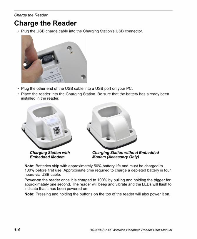
Charge the Reader• Plug the USB charge cable into the Charging Station’s USB connector.
• Plug the other end of the USB cable into a USB port on your PC.
• Place the reader into the Charging Station. Be sure that the battery has already been installed in the reader.
Note: Batteries ship with approximately 50% battery life and must be charged to 100% before first use. Approximate time required to charge a depleted battery is four hours via USB cable.
Power-on the reader once it is charged to 100% by pulling and holding the trigger for approximately one second. The reader will beep and vibrate and the LEDs will flash to indicate that it has been powered on.
Note: Pressing and holding the buttons on the top of the reader will also power it on.
Charging Station with Embedded Modem
Charging Station without Embedded Modem (Accessory Only)
Quick Start
HS-51/HS-51X Wireless Handheld Reader User Manual 1-5
Configure Hardware
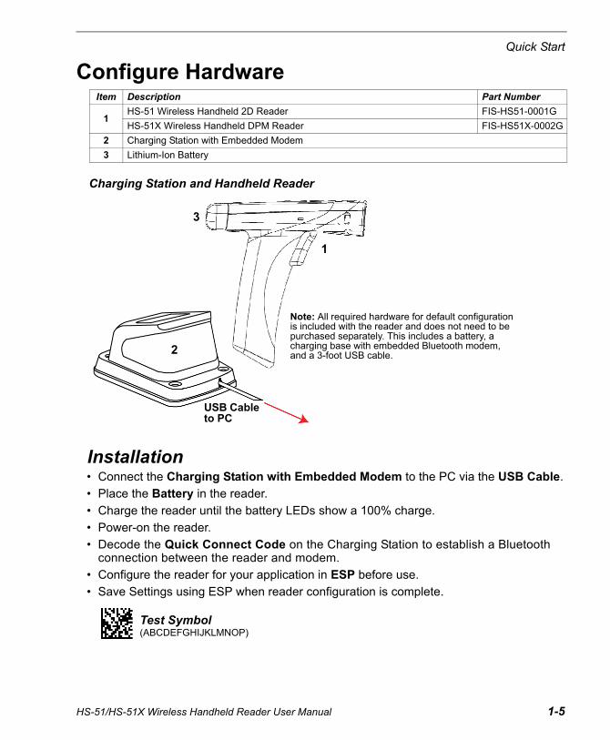
Installation• Connect the Charging Station with Embedded Modem to the PC via the USB Cable.
• Place the Battery in the reader.
• Charge the reader until the battery LEDs show a 100% charge.
• Power-on the reader.
• Decode the Quick Connect Code on the Charging Station to establish a Bluetooth connection between the reader and modem.
• Configure the reader for your application in ESP before use.
• Save Settings using ESP when reader configuration is complete.
Item Description Part Number
1HS-51 Wireless Handheld 2D Reader FIS-HS51-0001G
HS-51X Wireless Handheld DPM Reader FIS-HS51X-0002G
2 Charging Station with Embedded Modem
3 Lithium-Ion Battery
Charging Station and Handheld Reader
1
USB Cable to PC
3
2
Note: All required hardware for default configuration is included with the reader and does not need to be purchased separately. This includes a battery, a charging base with embedded Bluetooth modem, and a 3-foot USB cable.
Test Symbol(ABCDEFGHIJKLMNOP)

Install ESP
1-6 HS-51/HS-51X Wireless Handheld Reader User Manual
Install ESPESP Software is Microscan’s configuration and testing software. Use ESP to set up your HS-51 or HS-51X Wireless Handheld Reader.
ESP can be found on the Microscan Tools Drive that is shipped with the reader upon request.
1. Follow the prompts to install ESP from the Tools Drive.
2. Click on the ESP icon to run the program.
Note: ESP can also be installed from the Download Center at www.microscan.com.
Important: If you intend to use the reader’s Bluetooth functionality, click the Install the Microscan Bluetooth Driver check box when you see this dialog during installation.
Minimum System Requirements• 233 MHz Pentium PC• Windows 8, 7, Vista, or XP operating system (32-bit or 64-bit)• Internet Explorer 6.0 or higher• 128 MB RAM or greater• 160 MB free disk space• 800 x 600 256 color display (1024 x 768 32-bit color recommended)
Quick Start
HS-51/HS-51X Wireless Handheld Reader User Manual 1-7
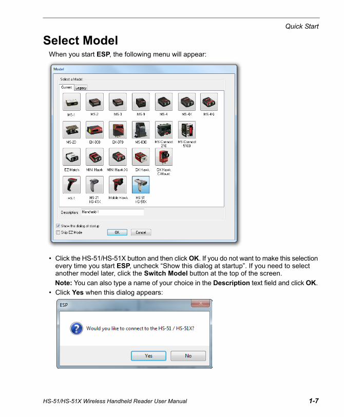
Select ModelWhen you start ESP, the following menu will appear:
• Click the HS-51/HS-51X button and then click OK. If you do not want to make this selection every time you start ESP, uncheck “Show this dialog at startup”. If you need to select another model later, click the Switch Model button at the top of the screen.
Note: You can also type a name of your choice in the Description text field and click OK.
• Click Yes when this dialog appears:

Connect to the Reader
Connect to the Reader• The USB dialog will appear. You will see the device ID in the Select Device field. Click Connect.
Note: You can also select Connection Wizard from the Connect dropdown menu or click the Connect button to access the USB dialog.
• When you are connected successfully, the CONNECTED message will appear in a green box in the status bar at the bottom right of the screen.
You are now ready to configure your reader using ESP. Subsequent sections provide more detailed information about ESP’s configuration options.
If the reader is already connected to the Bluetooth Modem, you will see the ID of your reader in the Select Device field. The reader ID number should match the serial number printed on the reader’s ID label.
If the reader is not yet connected to the modem, the Select Device field will show Bluetooth Modem. Decode the Quick Connect Code on the base of the modem to connect the reader to the modem. The reader ID will then appear.
or
1-8 HS-51/HS-51X Wireless Handheld Reader User Manual
Quick Start
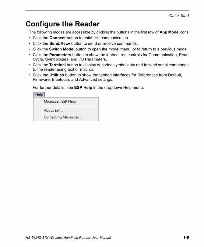
Configure the ReaderThe following modes are accessible by clicking the buttons in the first row of App Mode icons:
• Click the Connect button to establish communication.
• Click the Send/Recv button to send or receive commands.
• Click the Switch Model button to open the model menu, or to return to a previous model.
• Click the Parameters button to show the tabbed tree controls for Communication, Read Cycle, Symbologies, and I/O Parameters.
• Click the Terminal button to display decoded symbol data and to send serial commands to the reader using text or macros.
• Click the Utilities button to show the tabbed interfaces for Differences from Default, Firmware, Bluetooth, and Advanced settings.
For further details, see ESP Help in the dropdown Help menu.
HS-51/HS-51X Wireless Handheld Reader User Manual 1-9
Save Changes in ESP
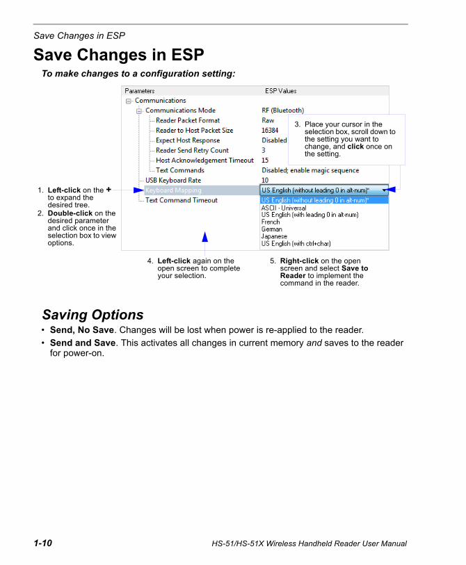
Save Changes in ESPTo make changes to a configuration setting:
Saving Options• Send, No Save. Changes will be lost when power is re-applied to the reader.
• Send and Save. This activates all changes in current memory and saves to the reader for power-on.
1. Left-click on the + to expand the desired tree.
2. Double-click on the desired parameter and click once in the selection box to view options.
5. Right-click on the open screen and select Save to Reader to implement the command in the reader.
4. Left-click again on the open screen to complete your selection.
3. Place your cursor in the selection box, scroll down to the setting you want to change, and click once on the setting.
1-10 HS-51/HS-51X Wireless Handheld Reader User Manual
2 Using ESPContents
This section is designed to help you understand the ESP interface.
Enter App Mode to access Communications, Read Cycle, Symbologies, I/O Parameters, a Terminal interface, and a Utilities interface.
ESP can be used to configure the HS-51 and HS-51X Wireless Handheld Readers in the following ways:
• Tree Controls: Each tree control contains a list of all commands that pertain to that specific category of reader operation. For example, the Communications menu shows a Communications Mode command which contains a dropdown menu showing the available communications modes.
• Graphic User Interfaces: Settings can be configured using point-and-click tools – radio buttons, spin boxes, check boxes, and drag-and-drop functions.
• Terminal: ESP’s Terminal allows you to send configuration and utility commands directly to the reader by typing them in the Send text field.
App Mode ..................................................................................................................................... 2-2Tree Controls................................................................................................................................ 2-3Menu Toolbar ............................................................................................................................... 2-4Send/Receive ............................................................................................................................ 2-14
HS-51/HS-51X Wireless Handheld Reader User Manual 2-1

App Mode
2-2 HS-51/HS-51X Wireless Handheld Reader User Manual
App ModeClick the App Mode button to access specific configuration menus, Utilities tools, and a Terminal window where serial commands can be entered.
Note: See the corresponding sections of this documentation for specific information on any of the views or modes mentioned above.
Click on tabs in this row to access configuration trees like the one shown here.
Click here to open the Terminal or Utilities views.
Click the Parameters icon to return to full App Mode view from Terminal or Utilities.

Using ESP
Tree ControlsTo make changes to configuration settings in the tree control menus:
Hint: To see the underlying serial command that corresponds with each tree control item, click on the item in the tree control and drag the mouse to the open screen. The command will be displayed between angle brackets.
2. Double click on the parameter and click once in the selection box to view options.
3. Place your cursor in the selection box, scroll down to the setting you want to change and click once on the setting.
4. Left click again on the open screen to complete the selection.
5. Right click on the open screen and select Save to Reader to implement the command in the reader.
1. Left click on the +/- to expand or collapse the tree.
In this example, the command for Read Cycle Timeout is shown.
HS-51/HS-51X Wireless Handheld Reader User Manual 2-3

Menu Toolbar
2-4 HS-51/HS-51X Wireless Handheld Reader User Manual
Menu Toolbar
File > NewWhenever New is selected from the File menu, the default configuration of ESP is loaded.
Open / SaveWhen Save or Save As is selected, the ESP configuration is saved to the host computer’s hard drive and available whenever the same file is selected under Open.
When you save menu changes to your hard drive, these changes are not saved to your reader. The diagram below shows how settings can be saved and received between ESP and the reader, and ESP and the host hard drive.
Import / ExportImport converts the ASCII settings from a text file to ESP configuration settings.
Export converts the active ESP configuration settings to an ASCII text file.
(Save to Reader)
(Receive Reader Settings)
Using ESP
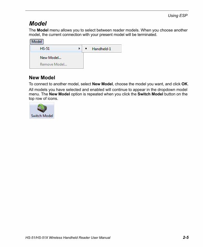
ModelThe Model menu allows you to select between reader models. When you choose another model, the current connection with your present model will be terminated.
New ModelTo connect to another model, select New Model, choose the model you want, and click OK.
All models you have selected and enabled will continue to appear in the dropdown model menu. The New Model option is repeated when you click the Switch Model button on the top row of icons.
HS-51/HS-51X Wireless Handheld Reader User Manual 2-5
Menu Toolbar
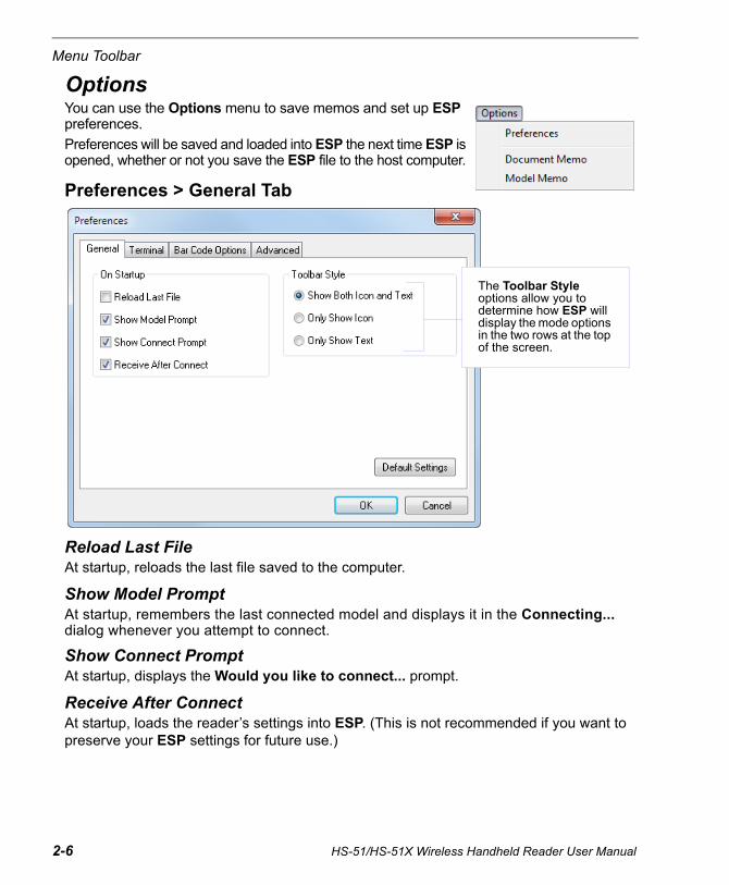
OptionsYou can use the Options menu to save memos and set up ESP preferences.
Preferences will be saved and loaded into ESP the next time ESP is opened, whether or not you save the ESP file to the host computer.
Preferences > General Tab
Reload Last FileAt startup, reloads the last file saved to the computer.
Show Model PromptAt startup, remembers the last connected model and displays it in the Connecting... dialog whenever you attempt to connect.
Show Connect Prompt At startup, displays the Would you like to connect... prompt.
Receive After ConnectAt startup, loads the reader’s settings into ESP. (This is not recommended if you want to preserve your ESP settings for future use.)
The Toolbar Style options allow you to determine how ESP will display the mode options in the two rows at the top of the screen.
2-6 HS-51/HS-51X Wireless Handheld Reader User Manual
Using ESP
HS-51/HS-51X Wireless Handheld Reader User Manual 2-7
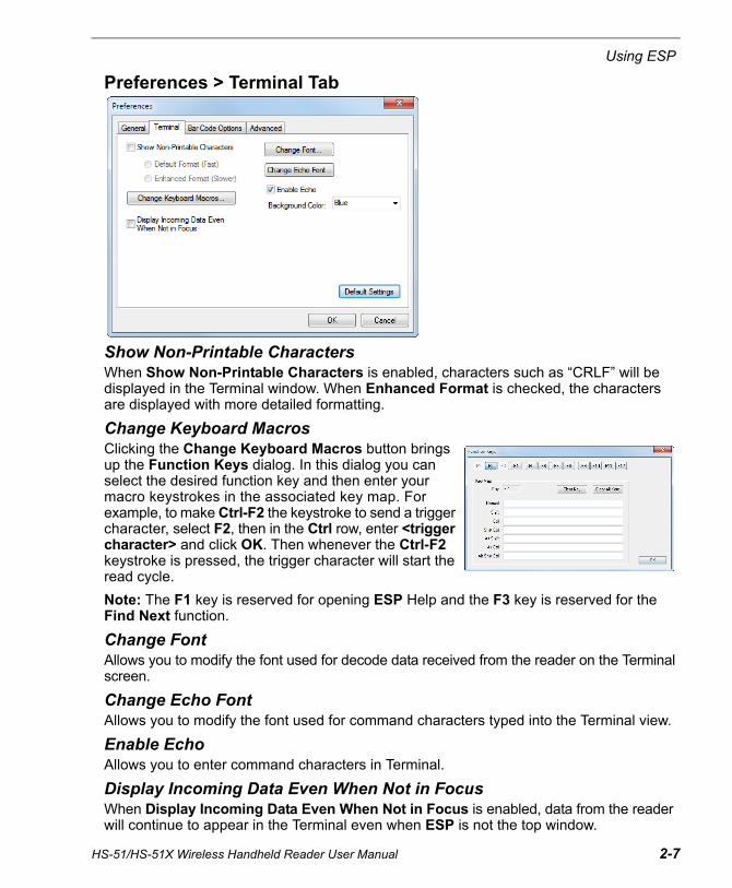
Preferences > Terminal Tab
Show Non-Printable Characters When Show Non-Printable Characters is enabled, characters such as “CRLF” will be displayed in the Terminal window. When Enhanced Format is checked, the characters are displayed with more detailed formatting.
Change Keyboard MacrosClicking the Change Keyboard Macros button brings up the Function Keys dialog. In this dialog you can select the desired function key and then enter your macro keystrokes in the associated key map. For example, to make Ctrl-F2 the keystroke to send a trigger character, select F2, then in the Ctrl row, enter <trigger character> and click OK. Then whenever the Ctrl-F2 keystroke is pressed, the trigger character will start the read cycle.
Note: The F1 key is reserved for opening ESP Help and the F3 key is reserved for the Find Next function.
Change FontAllows you to modify the font used for decode data received from the reader on the Terminal screen.
Change Echo FontAllows you to modify the font used for command characters typed into the Terminal view.
Enable EchoAllows you to enter command characters in Terminal.
Display Incoming Data Even When Not in FocusWhen Display Incoming Data Even When Not in Focus is enabled, data from the reader will continue to appear in the Terminal even when ESP is not the top window.
Menu Toolbar
2-8 HS-51/HS-51X Wireless Handheld Reader User Manual
Preferences > Bar Code Options Tab
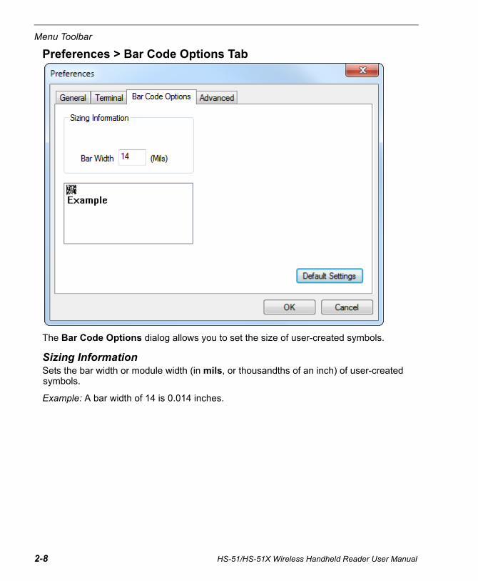
The Bar Code Options dialog allows you to set the size of user-created symbols.
Sizing InformationSets the bar width or module width (in mils, or thousandths of an inch) of user-created symbols.
Example: A bar width of 14 is 0.014 inches.
Using ESP
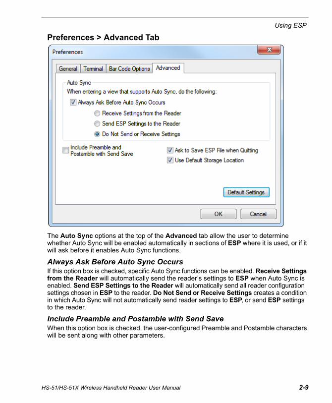
Preferences > Advanced Tab
The Auto Sync options at the top of the Advanced tab allow the user to determine whether Auto Sync will be enabled automatically in sections of ESP where it is used, or if it will ask before it enables Auto Sync functions.
Always Ask Before Auto Sync OccursIf this option box is checked, specific Auto Sync functions can be enabled. Receive Settings from the Reader will automatically send the reader’s settings to ESP when Auto Sync is enabled. Send ESP Settings to the Reader will automatically send all reader configuration settings chosen in ESP to the reader. Do Not Send or Receive Settings creates a condition in which Auto Sync will not automatically send reader settings to ESP, or send ESP settings to the reader.
Include Preamble and Postamble with Send SaveWhen this option box is checked, the user-configured Preamble and Postamble characters will be sent along with other parameters.
HS-51/HS-51X Wireless Handheld Reader User Manual 2-9
Menu Toolbar
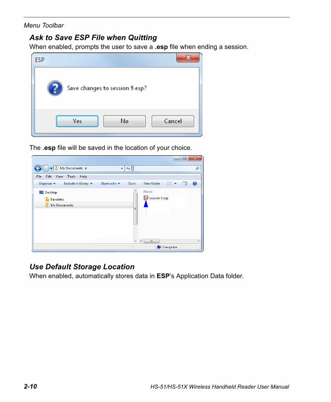
Ask to Save ESP File when QuittingWhen enabled, prompts the user to save a .esp file when ending a session.
The .esp file will be saved in the location of your choice.
Use Default Storage LocationWhen enabled, automatically stores data in ESP’s Application Data folder.
2-10 HS-51/HS-51X Wireless Handheld Reader User Manual
Using ESP
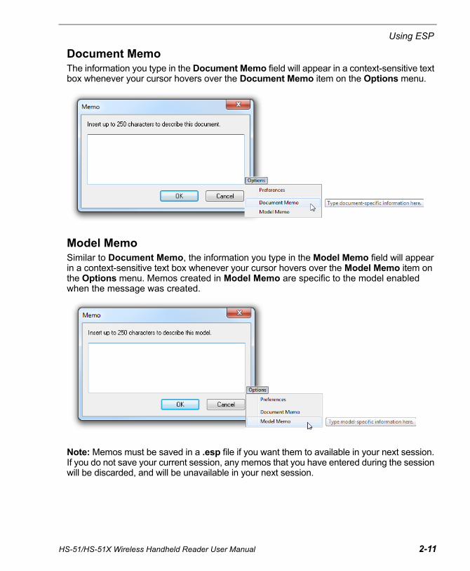
Document MemoThe information you type in the Document Memo field will appear in a context-sensitive text box whenever your cursor hovers over the Document Memo item on the Options menu.
Model MemoSimilar to Document Memo, the information you type in the Model Memo field will appear in a context-sensitive text box whenever your cursor hovers over the Model Memo item on the Options menu. Memos created in Model Memo are specific to the model enabled when the message was created.
Note: Memos must be saved in a .esp file if you want them to available in your next session. If you do not save your current session, any memos that you have entered during the session will be discarded, and will be unavailable in your next session.
HS-51/HS-51X Wireless Handheld Reader User Manual 2-11

Menu Toolbar
ConnectThe Connect dropdown menu allows you to access the Connection Wizard, and also to Disconnect ESP from the reader.
Connection WizardTo connect using the Connection Wizard:
• Click Connect on ESP’s menu toolbar, and then select Connection Wizard.
• Click Connect when you see the reader’s name and serial number in the Select Device field.
Note: If the reader is not yet connected to the modem, the Select Device field will show Bluetooth Modem as the device instead of the reader. Decode the Quick Connect Code on the base of the modem to connect the reader to the modem. The reader ID will then appear. Click Connect to continue.
• When a connection is established, the green indicator in the status bar at the bottom right of the screen will be visible.
Bluetooth Modem will appear in the Select Device field if there is not a connection between the reader and modem. Decode the Quick Connect Code to establish a connection.
2-12 HS-51/HS-51X Wireless Handheld Reader User Manual
Using ESP
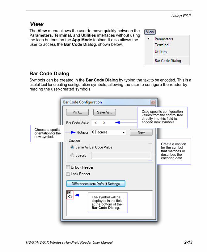
ViewThe View menu allows the user to move quickly between the Parameters, Terminal, and Utilities interfaces without using the icon buttons on the App Mode toolbar. It also allows the user to access the Bar Code Dialog, shown below.
Bar Code DialogSymbols can be created in the Bar Code Dialog by typing the text to be encoded. This is a useful tool for creating configuration symbols, allowing the user to configure the reader by reading the user-created symbols.
Drag specific configuration values from the control tree directly into this field to encode new symbols.
Choose a spatial orientation for the new symbol.
Create a caption for the symbol that matches or describes the encoded data.
The symbol will be displayed in the field at the bottom of the Bar Code Dialog.
HS-51/HS-51X Wireless Handheld Reader User Manual 2-13
Send/Receive
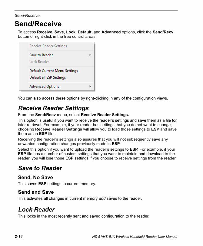
Send/Receive To access Receive, Save, Lock, Default, and Advanced options, click the Send/Recv button or right-click in the tree control areas.
You can also access these options by right-clicking in any of the configuration views.
Receive Reader SettingsFrom the Send/Recv menu, select Receive Reader Settings.
This option is useful if you want to receive the reader’s settings and save them as a file for later retrieval. For example, if your reader has settings that you do not want to change, choosing Receive Reader Settings will allow you to load those settings to ESP and save them as an ESP file.
Receiving the reader’s settings also assures that you will not subsequently save any unwanted configuration changes previously made in ESP.
Select this option if you want to upload the reader’s settings to ESP. For example, if your ESP file has a number of custom settings that you want to maintain and download to the reader, you will lose those ESP settings if you choose to receive settings from the reader.
Save to Reader
Send, No SaveThis saves ESP settings to current memory.
Send and Save This activates all changes in current memory and saves to the reader.
Lock ReaderThis locks in the most recently sent and saved configuration to the reader.
2-14 HS-51/HS-51X Wireless Handheld Reader User Manual
Using ESP
Default Current Menu SettingsThis option returns the settings in the current tree control to their defaults.
Important: When you select Default Current Menu Settings you are only defaulting settings in ESP. The reader is not affected unless you download new settings.
Default all ESP SettingsThis option returns all settings in ESP to their defaults.
Important: When you select Default all ESP Settings you are only defaulting settings in ESP. The reader is not affected unless you download new settings.
Advanced Options
Send Current View This is the same as Save to Reader > Send, No Save except that only the commands in the current tree control are sent.
Send Current CommandThis is the same as Send Current View except that it only saves the command that is currently selected.
HS-51/HS-51X Wireless Handheld Reader User Manual 2-15

Send/Receive
2-16 HS-51/HS-51X Wireless Handheld Reader User Manual
3 Basic OperationsContents
This section explains how to practice targeting and triggering, and also describes the reader’s Dual Optics and Operational Feedback behaviors.
Practice Targeting ........................................................................................................................ 3-2Dual Optics................................................................................................................................... 3-3Operational Feedback .................................................................................................................. 3-5
HS-51/HS-51X Wireless Handheld Reader User Manual 3-1
Practice Targeting
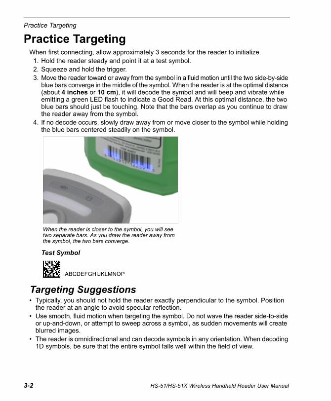
Practice TargetingWhen first connecting, allow approximately 3 seconds for the reader to initialize.
1. Hold the reader steady and point it at a test symbol.2. Squeeze and hold the trigger.3. Move the reader toward or away from the symbol in a fluid motion until the two side-by-side
blue bars converge in the middle of the symbol. When the reader is at the optimal distance (about 4 inches or 10 cm), it will decode the symbol and will beep and vibrate while emitting a green LED flash to indicate a Good Read. At this optimal distance, the two blue bars should just be touching. Note that the bars overlap as you continue to draw the reader away from the symbol.
4. If no decode occurs, slowly draw away from or move closer to the symbol while holding the blue bars centered steadily on the symbol.
Test Symbol
Targeting Suggestions• Typically, you should not hold the reader exactly perpendicular to the symbol. Position
the reader at an angle to avoid specular reflection.• Use smooth, fluid motion when targeting the symbol. Do not wave the reader side-to-side
or up-and-down, or attempt to sweep across a symbol, as sudden movements will create blurred images.
• The reader is omnidirectional and can decode symbols in any orientation. When decoding 1D symbols, be sure that the entire symbol falls well within the field of view.
When the reader is closer to the symbol, you will see two separate bars. As you draw the reader away from the symbol, the two bars converge.
ABCDEFGHIJKLMNOP
3-2 HS-51/HS-51X Wireless Handheld Reader User Manual

Basic Operations
HS-51/HS-51X Wireless Handheld Reader User Manual 3-3
Dual OpticsThe reader’s dual field optical system can read small 2D symbols as well as larger 1D symbols. An image is captured from each field. The decoder first operates on the image (High Density or Wide Angle) which was successfully decoded on the last cycle. If unsuccessful, the next image is decoded.
Move the reader closer to decode smaller symbols and farther away to decode larger symbols.
Imaging Area
The reader’s optics are divided into High Density and Wide Angle decode zones. Each decode zone is 960 x 640 pixels.
Wide Angle
High Density
960
640
640
(1280)
Field of View: 30° horiz. by 20° vert.Focal Point: Approximately 100 mm
Field of View: 50° horiz. by 33.5° vert.Focal Point: Approximately 115 mm

Dual Optics
Dual Optics Examples
20 mil Data Matrix
5 mil Code 39
Dual Field
Wide Angle
High Density
Dual Field
Wide Angle
High Density
3-4 HS-51/HS-51X Wireless Handheld Reader User Manual
Basic Operations
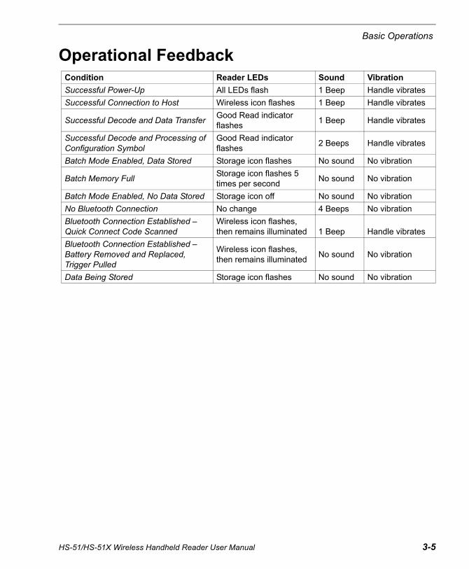
Operational FeedbackCondition Reader LEDs Sound Vibration
Successful Power-Up All LEDs flash 1 Beep Handle vibrates
Successful Connection to Host Wireless icon flashes 1 Beep Handle vibrates
Successful Decode and Data TransferGood Read indicator flashes
1 Beep Handle vibrates
Successful Decode and Processing of Configuration Symbol
Good Read indicator flashes
2 Beeps Handle vibrates
Batch Mode Enabled, Data Stored Storage icon flashes No sound No vibration
Batch Memory FullStorage icon flashes 5 times per second
No sound No vibration
Batch Mode Enabled, No Data Stored Storage icon off No sound No vibration
No Bluetooth Connection No change 4 Beeps No vibration
Bluetooth Connection Established – Quick Connect Code Scanned
Wireless icon flashes, then remains illuminated 1 Beep Handle vibrates
Bluetooth Connection Established – Battery Removed and Replaced, Trigger Pulled
Wireless icon flashes, then remains illuminated
No sound No vibration
Data Being Stored Storage icon flashes No sound No vibration
HS-51/HS-51X Wireless Handheld Reader User Manual 3-5

Operational Feedback
3-6 HS-51/HS-51X Wireless Handheld Reader User Manual

4 CommunicationsContents
This section explains how to set up communications between the reader and a host.
ESP can be used to configure reader parameters and then to send and save those parameters to the reader.
You can also configure reader parameters by decoding the Data Matrix symbols in this section.
Communications by ESP.............................................................................................................. 4-2Communications Overview........................................................................................................... 4-3Bluetooth ...................................................................................................................................... 4-4Batch Mode .................................................................................................................................. 4-6Preamble ...................................................................................................................................... 4-9Postamble................................................................................................................................... 4-10Preamble and Postamble by ESP .............................................................................................. 4-11Keyboard Mapping ..................................................................................................................... 4-12USB Keyboard Rate ................................................................................................................... 4-13Text Command Timeout ............................................................................................................. 4-14Other Communications Mode Commands ................................................................................. 4-15
HS-51/HS-51X Wireless Handheld Reader User Manual 4-1
Communications by ESP
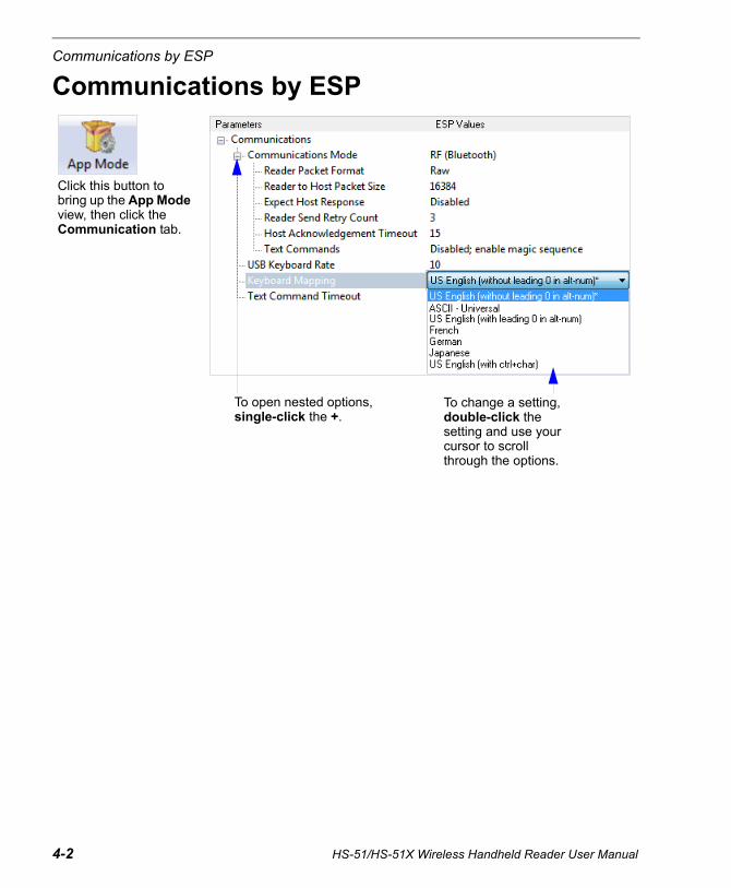
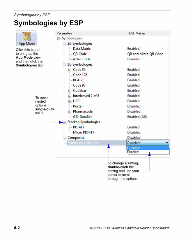
Communications by ESP
Click this button to bring up the App Mode view, then click the Communication tab.
To open nested options, single-click the +.
To change a setting, double-click the setting and use your cursor to scroll through the options.
4-2 HS-51/HS-51X Wireless Handheld Reader User Manual
Communications
HS-51/HS-51X Wireless Handheld Reader User Manual 4-3
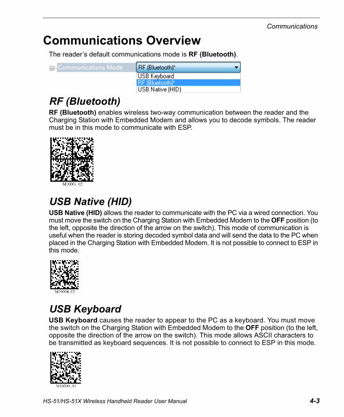
Communications OverviewThe reader’s default communications mode is RF (Bluetooth).
RF (Bluetooth)RF (Bluetooth) enables wireless two-way communication between the reader and the Charging Station with Embedded Modem and allows you to decode symbols. The reader must be in this mode to communicate with ESP.
USB Native (HID)USB Native (HID) allows the reader to communicate with the PC via a wired connection. You must move the switch on the Charging Station with Embedded Modem to the OFF position (to the left, opposite the direction of the arrow on the switch). This mode of communication is useful when the reader is storing decoded symbol data and will send the data to the PC when placed in the Charging Station with Embedded Modem. It is not possible to connect to ESP in this mode.
USB KeyboardUSB Keyboard causes the reader to appear to the PC as a keyboard. You must move the switch on the Charging Station with Embedded Modem to the OFF position (to the left, opposite the direction of the arrow on the switch). This mode allows ASCII characters to be transmitted as keyboard sequences. It is not possible to connect to ESP in this mode.
Bluetooth
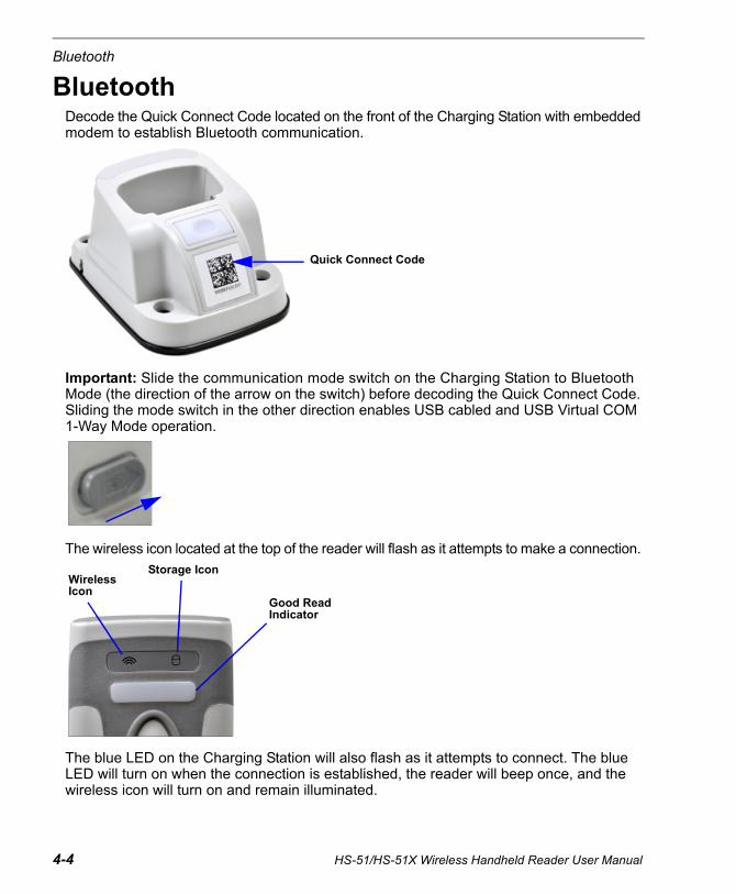
BluetoothDecode the Quick Connect Code located on the front of the Charging Station with embedded modem to establish Bluetooth communication.
Important: Slide the communication mode switch on the Charging Station to Bluetooth Mode (the direction of the arrow on the switch) before decoding the Quick Connect Code. Sliding the mode switch in the other direction enables USB cabled and USB Virtual COM 1-Way Mode operation.
The wireless icon located at the top of the reader will flash as it attempts to make a connection.
The blue LED on the Charging Station will also flash as it attempts to connect. The blue LED will turn on when the connection is established, the reader will beep once, and the wireless icon will turn on and remain illuminated.
Quick Connect Code
Wireless Icon
Storage Icon
Good Read Indicator
4-4 HS-51/HS-51X Wireless Handheld Reader User Manual
Communications
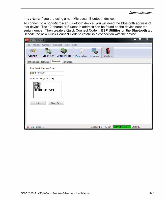
HS-51/HS-51X Wireless Handheld Reader User Manual 4-5
Important: If you are using a non-Microscan Bluetooth device:
To connect to a non-Microscan Bluetooth device, you will need the Bluetooth address of that device. The 12-character Bluetooth address can be found on the device near the serial number. Then create a Quick Connect Code in ESP Utilities on the Bluetooth tab. Decode the new Quick Connect Code to establish a connection with the device.

Batch Mode
4-6 HS-51/HS-51X Wireless Handheld Reader User Manual
Batch ModeThe HS-51 and HS-51X can be configured for Batch Mode, which allows you to capture, store, and transmit data via standard communication.
Decode the Batch Mode symbol below that best suits your application’s data storage needs. Batch Mode is disabled by default.
Batch Mode Enabled – Send and LogWhen the reader is configured for Send and Log, decoded data is immediately sent to the PC and a copy is saved to the reader.
Batch Mode Enabled – Log OnlyWhen the reader is configured for Log Only, decoded data is only stored in reader memory and not sent to the PC. Decode the Batch Mode – Transfer All Data in Memory symbol to send all data that has been saved on the reader to the PC.
Batch Mode Indicators
Batch Mode Enabled – Send and Log
Batch Mode Enabled – Log Only
Batch Mode Disabled (Default)
Batch Mode – Transfer All Data in Memory
Wireless Icon
Storage Icon
Good Read Indicator

Communications
HS-51/HS-51X Wireless Handheld Reader User Manual 4-7
Configuring and Using Batch ModeFollow the procedure below to set up and use Batch Mode.
• Plug in the Charging Station with Embedded Modem.
• Move the switch on the Charging Station with Embedded Modem to the left (opposite the direction of the arrow on the switch).
• Decode the Default Reader Settings symbol.
• Decode the Clear All Stored Data, Images, and JavaScripts symbol.
• Decode the Batch Mode Enabled – Log Only symbol.
• Decode the USB Keyboard Mode symbol.
• Use the reader to capture symbol data and log it to the reader as needed. The Storage Icon on top of the reader will illuminate as symbols are decoded and logged.
• Place the reader in the Charging Station with Embedded Modem’s dock to transfer logged data to the PC. A Microsoft Keyboard driver will load and data will then be sent to the PC after approximately 10 seconds.
Default Reader Settings
Clear All Stored Data, Images, and JavaScripts
Batch Mode Enabled – Log Only
USB Keyboard Mode

Batch Mode
4-8 HS-51/HS-51X Wireless Handheld Reader User Manual
USB Virtual COM 1-Way Mode (for Serial Emulation)USB Virtual COM 1-Way Mode (for Serial Emulation) is available for applications in which the reader must function as a virtual serial COM port. This mode requires installation of a USB Virtual COM driver, which is available in the Download Center on the Microscan website under the red driver icon shown below. You will see this icon at the end of the HS-51 and HS-51X rows.
The USB Virtual COM Port Driver is also available on the Microscan Tools Drive from the Accessories navigation page:
Once the driver is installed, follow the steps below to use this communications mode.
• Switch the Charging Station with Embedded Modem from Bluetooth Mode to USB Mode.
• Scan the Batch Mode Enabled – Send and Log configuration symbol below.
• Scan the USB Virtual COM 1-Way Mode (for Serial Emulation) configuration symbol below.
The reader can now be used as a virtual serial COM port. Symbol data will be sent to the assigned COM port 5 seconds after the reader is placed in the Charging Station dock.
Batch Mode Enabled – Send and Log
USB Virtual COM 1-Way Mode (for Serial Emulation)

Communications
PreambleA preamble is a character that is added to the beginning of a decoded data string.
Set the desired preamble by reading the appropriate symbol below.
Important: Preamble settings are not concatenated when their configuration symbols are decoded in series. For example, if you set Comma as your preamble and then set Space, the preamble will not be the series Comma and Space – it will simply be Space. The most recently decoded configuration symbol will overwrite the previously decoded configuration symbol.
If you wish to concatenate preamble characters, use Preamble and Postamble by ESP on ESP’s Communications tab.
Comma Space
Erase Preamble and Postamble Data
Tab Erase/None (Default)
HS-51/HS-51X Wireless Handheld Reader User Manual 4-9

Postamble
4-10 HS-51/HS-51X Wireless Handheld Reader User Manual
PostambleA postamble is a character that is added to the end of a decoded data string.
Set the desired postamble by reading the appropriate symbol below.
Important: Postamble settings are not concatenated when their configuration symbols are decoded in series. For example, if you set Comma as your postamble and then set Space, the postamble will not be the series Comma and Space – it will simply be Space. The most recently decoded configuration symbol will overwrite the previously decoded configuration symbol.
If you wish to concatenate postamble characters, use Preamble and Postamble by ESP on ESP’s Communications tab.
Erase Preamble and Postamble Data
Comma Space
Erase/None (Default)
Tab Enter
Communications
HS-51/HS-51X Wireless Handheld Reader User Manual 4-11
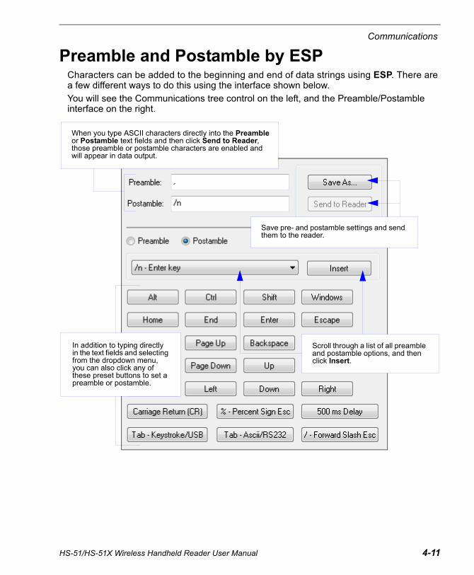
Preamble and Postamble by ESPCharacters can be added to the beginning and end of data strings using ESP. There are a few different ways to do this using the interface shown below.
You will see the Communications tree control on the left, and the Preamble/Postamble interface on the right.
Scroll through a list of all preamble and postamble options, and then click Insert.
In addition to typing directly in the text fields and selecting from the dropdown menu, you can also click any of these preset buttons to set a preamble or postamble.
Save pre- and postamble settings and send them to the reader.
When you type ASCII characters directly into the Preamble or Postamble text fields and then click Send to Reader, those preamble or postamble characters are enabled and will appear in data output.

Keyboard Mapping
Keyboard MappingThe Keyboard Mapping feature provides alternatives for keyboards that do not conform to U.S. English mapping. It also allows you to send control characters for non-printable ASCII.
Note: Universal keyboard mapping is slightly slower than the other language-specific options, because it maps data by reference to the full set of ASCII characters. The advantage of Universal keyboard mapping is that it allows any language and keyboard layout to be mapped.
Important: Keyboard Mapping is not to be confused with USB Keyboard Mode, which has an entirely different function—namely to enable USB cabled communications.
Keyboard Mapping by ESP
U.S., No Leading 0 (Default)
U.S. with Leading 0 Keyboard Control Characters for Non-Printable ASCII
French German Japanese
Universal
4-12 HS-51/HS-51X Wireless Handheld Reader User Manual

Communications
USB Keyboard Rate
Requests that the host polls the USB reader at the rate specified (1 to 255 ms).
HS-51/HS-51X Wireless Handheld Reader User Manual 4-13
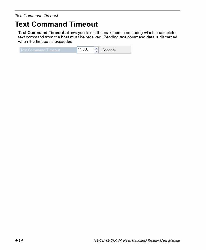
Text Command Timeout
Text Command TimeoutText Command Timeout allows you to set the maximum time during which a complete text command from the host must be received. Pending text command data is discarded when the timeout is exceeded.
4-14 HS-51/HS-51X Wireless Handheld Reader User Manual

Communications
Other Communications Mode CommandsSome ESP Communications options are unique to the software, and do not have corresponding programming symbols. These options are explained below.
Reader Packet Format
Data that is sent from the reader to the host in Raw format is sent without packet framing or check characters.
Packet data is sent with framing (a preamble communicating the amount of data to be transmitted, and a postamble containing error detection) and check characters, and a response is expected from the host.
Packet Mode Version 0 is a similar but more streamlined way of sending packetized data.
Reader to Host Packet Size
The Reader to Host Packet Size is the amount of data (in bytes) that is sent to the host in packet format. This feature allows you to set the maximum allowable packet size.
Expect Host Response
When Expect Host Response is enabled, the reader will re-transmit data if it doesn’t receive acknowledgement from the host.
Reader Send Retry Count
Reader Send Retry Count sets the number of times the reader will re-transmit data before abandoning further send attempts. The minimum retry count is 1, which represents the initial transmission.
Host Acknowledgement Timeout
The Host Acknowledgement Timeout is the amount of time (in seconds) that the reader will wait for an acknowledgement from the host before re-sending data.
HS-51/HS-51X Wireless Handheld Reader User Manual 4-15

Other Communications Mode Commands
Text CommandsWhen the Text Commands feature is enabled, the reader can accept text commands via USB Virtual COM modes.
Note: Text Commands are not supported in USB HID Mode.
Text Commands by ESP
Entering Magic SequenceThe magic sequence is ;>PA followed by a numeric value of 1, 3, or 7.
1 = Enable Text Commands3 = Enabled; Suppress Echo7 = Enabled; Suppress Echo and ResponsesIn the example below, the magic sequence entered will Enable Text Commands and Suppress Echo and Responses.
Enable Text Commands Disable Text Commands (Default)
When Text Commands are set to Enabled; Suppress Echo, text that a user enters in the Terminal will not be shown. When Text Commands are set to Enabled; Suppress Echo and Responses, neither user-entered data or reader responses will be shown, and only decoded symbol data will appear in the Terminal.See Terminal Right-Click Menu for a way to change Echo settings directly in the Terminal view.
When Magic Sequence is enabled, it allows the user to enable Text Commands by entering a predetermined series of keystrokes.
Enter the magic sequence in this text field and click Send.
Once the magic sequence has been sent, you can send text commands from the same text field.
4-16 HS-51/HS-51X Wireless Handheld Reader User Manual

HS-51/HS-51X Wireless Handheld Reader User Manual 5-1
5 Read CycleContents
This section explains Read Cycle parameters, which can be configured to optimize reader performance in your application.
ESP can be used to configure reader parameters and then to send and save those parameters to the reader.
Read Cycle by ESP...................................................................................................................... 5-2Trigger Active ............................................................................................................................... 5-3Default Continuous Event............................................................................................................. 5-4Maximum Decodes per Read....................................................................................................... 5-5Read Cycle Timeout..................................................................................................................... 5-6Ignore Duplicate Symbol Timeout ................................................................................................ 5-7Targeting Zone Tolerance ............................................................................................................ 5-8Morphological Preprocessing ....................................................................................................... 5-9Camera Settings......................................................................................................................... 5-10

5-2 HS-51/HS-51X Wireless Handheld Reader User Manual
Read Cycle by ESP
Read Cycle by ESP
To change a setting, double-click the setting and use your cursor to scroll through the options.
Click this button to bring up the App Mode view, and then click the Read Cycle tab.
To open nested options, single-click the +.
HS-51/HS-51X Wireless Handheld Reader User Manual 5-3
Read Cycle
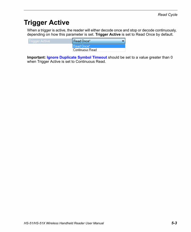
Trigger ActiveWhen a trigger is active, the reader will either decode once and stop or decode continuously, depending on how this parameter is set. Trigger Active is set to Read Once by default.
Important: Ignore Duplicate Symbol Timeout should be set to a value greater than 0 when Trigger Active is set to Continuous Read.
5-4 HS-51/HS-51X Wireless Handheld Reader User Manual
Default Continuous Event
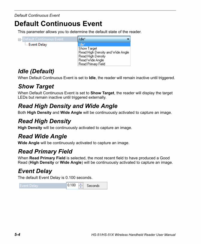
Default Continuous EventThis parameter allows you to determine the default state of the reader.
Idle (Default)When Default Continuous Event is set to Idle, the reader will remain inactive until triggered.
Show TargetWhen Default Continuous Event is set to Show Target, the reader will display the target LEDs but remain inactive until triggered externally.
Read High Density and Wide AngleBoth High Density and Wide Angle will be continuously activated to capture an image.
Read High DensityHigh Density will be continuously activated to capture an image.
Read Wide AngleWide Angle will be continuously activated to capture an image.
Read Primary FieldWhen Read Primary Field is selected, the most recent field to have produced a Good Read (High Density or Wide Angle) will be continuously activated to capture an image.
Event DelayThe default Event Delay is 0.100 seconds.
HS-51/HS-51X Wireless Handheld Reader User Manual 5-5
Read Cycle
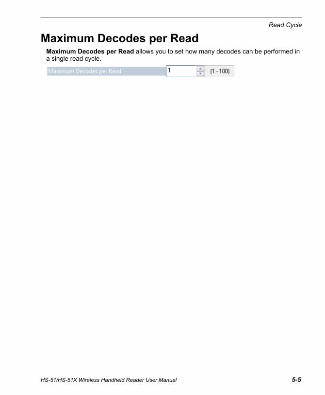
Maximum Decodes per ReadMaximum Decodes per Read allows you to set how many decodes can be performed in a single read cycle.
5-6 HS-51/HS-51X Wireless Handheld Reader User Manual
Read Cycle Timeout
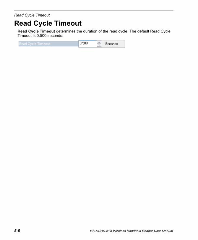
Read Cycle TimeoutRead Cycle Timeout determines the duration of the read cycle. The default Read Cycle Timeout is 0.500 seconds.
HS-51/HS-51X Wireless Handheld Reader User Manual 5-7
Read Cycle
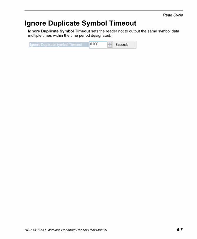
Ignore Duplicate Symbol TimeoutIgnore Duplicate Symbol Timeout sets the reader not to output the same symbol data multiple times within the time period designated.
5-8 HS-51/HS-51X Wireless Handheld Reader User Manual
Targeting Zone Tolerance
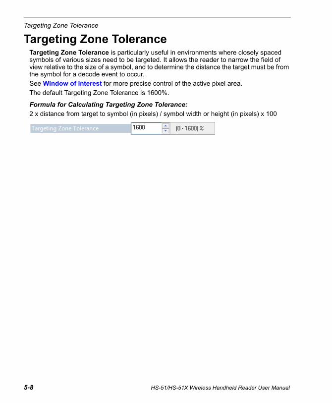
Targeting Zone ToleranceTargeting Zone Tolerance is particularly useful in environments where closely spaced symbols of various sizes need to be targeted. It allows the reader to narrow the field of view relative to the size of a symbol, and to determine the distance the target must be from the symbol for a decode event to occur.
See Window of Interest for more precise control of the active pixel area.
The default Targeting Zone Tolerance is 1600%.
Formula for Calculating Targeting Zone Tolerance:
2 x distance from target to symbol (in pixels) / symbol width or height (in pixels) x 100
HS-51/HS-51X Wireless Handheld Reader User Manual 5-9
Read Cycle
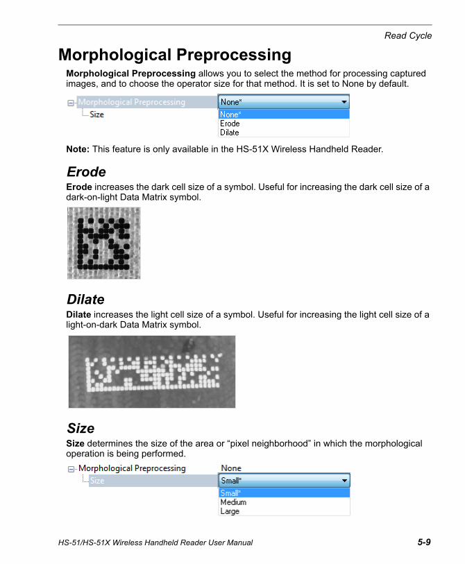
Morphological PreprocessingMorphological Preprocessing allows you to select the method for processing captured images, and to choose the operator size for that method. It is set to None by default.
Note: This feature is only available in the HS-51X Wireless Handheld Reader.
ErodeErode increases the dark cell size of a symbol. Useful for increasing the dark cell size of a dark-on-light Data Matrix symbol.
DilateDilate increases the light cell size of a symbol. Useful for increasing the light cell size of a light-on-dark Data Matrix symbol.
SizeSize determines the size of the area or “pixel neighborhood” in which the morphological operation is being performed.
5-10 HS-51/HS-51X Wireless Handheld Reader User Manual
Camera Settings
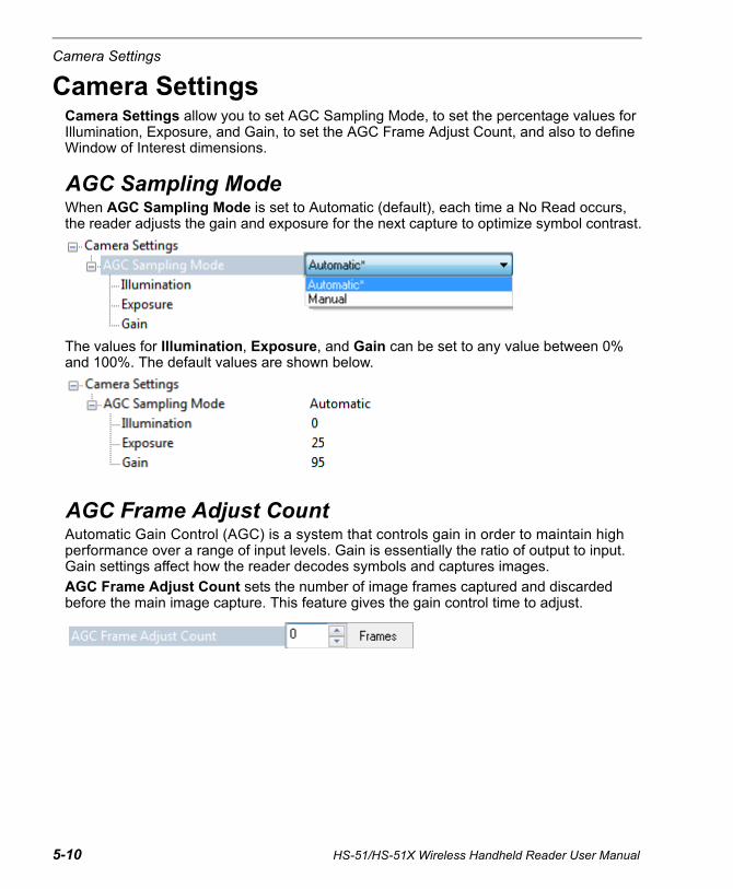
Camera SettingsCamera Settings allow you to set AGC Sampling Mode, to set the percentage values for Illumination, Exposure, and Gain, to set the AGC Frame Adjust Count, and also to define Window of Interest dimensions.
AGC Sampling ModeWhen AGC Sampling Mode is set to Automatic (default), each time a No Read occurs, the reader adjusts the gain and exposure for the next capture to optimize symbol contrast.
The values for Illumination, Exposure, and Gain can be set to any value between 0% and 100%. The default values are shown below.
AGC Frame Adjust CountAutomatic Gain Control (AGC) is a system that controls gain in order to maintain high performance over a range of input levels. Gain is essentially the ratio of output to input. Gain settings affect how the reader decodes symbols and captures images.
AGC Frame Adjust Count sets the number of image frames captured and discarded before the main image capture. This feature gives the gain control time to adjust.

HS-51/HS-51X Wireless Handheld Reader User Manual 5-11
Read Cycle
Window of InterestThe active pixel area of the image sensor is called the Window of Interest (WOI). The WOI allows the user to select an area of the field of view in which the desired symbol is located.
The programmable window of interest increases decode speed, improves threshold, and makes it easy to select specific symbols from among several in the field of view. The user provides the upper-left pixel location and the size of the window to define the Window of Interest.
Note: The Window of Interest can be changed, but captured images cannot be viewed.
High Density Window of Interest
Wide Angle Window of Interest

5-12 HS-51/HS-51X Wireless Handheld Reader User Manual
Camera Settings
6 SymbologiesContents
This section describes the various symbologies that can be decoded by the HS-51 and HS-51X Wireless Handheld Readers.
ESP can be used to configure reader parameters and then to send and save those parameters to the reader.
You can also configure reader parameters by decoding the Data Matrix symbols in this section.
Symbologies by ESP ....................................................................................................................6-2Data Matrix....................................................................................................................................6-3QR Code .......................................................................................................................................6-4Aztec Code ...................................................................................................................................6-5Code 39 ........................................................................................................................................6-6Code 128 ......................................................................................................................................6-7BC412 ...........................................................................................................................................6-8Code 93 ........................................................................................................................................6-9Codabar ......................................................................................................................................6-10Interleaved 2 of 5 ........................................................................................................................6-11UPC ............................................................................................................................................6-12Postal ..........................................................................................................................................6-13Pharmacode................................................................................................................................6-14GS1 DataBar...............................................................................................................................6-16PDF417.......................................................................................................................................6-17MicroPDF417 ..............................................................................................................................6-18Composite...................................................................................................................................6-19Symbology Identifier ...................................................................................................................6-20
HS-51/HS-51X Wireless Handheld Reader User Manual 6-1
Symbologies by ESP
Symbologies by ESP
To change a setting, double-click the setting and use your cursor to scroll through the options.
Click this button to bring up the App Mode view, and then click the Symbologies tab.
To open nested options, single-click the +.
6-2 HS-51/HS-51X Wireless Handheld Reader User Manual
Symbologies
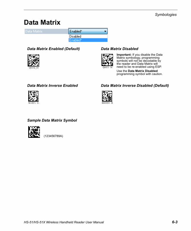
Data Matrix
Data Matrix Enabled (Default) Data Matrix Disabled
Data Matrix Inverse Enabled Data Matrix Inverse Disabled (Default)
Sample Data Matrix Symbol
Important: If you disable the Data Matrix symbology, programming symbols will not be decodable by the reader and Data Matrix will need to be re-enabled using ESP.Use the Data Matrix Disabled programming symbol with caution.
(123456789A)
HS-51/HS-51X Wireless Handheld Reader User Manual 6-3

QR Code
QR Code
QR Code Enabled (Default) QR Code Disabled
Sample QR Code Symbol Sample Micro QR Code Symbol
(Microscan QR)
6-4 HS-51/HS-51X Wireless Handheld Reader User Manual
Symbologies
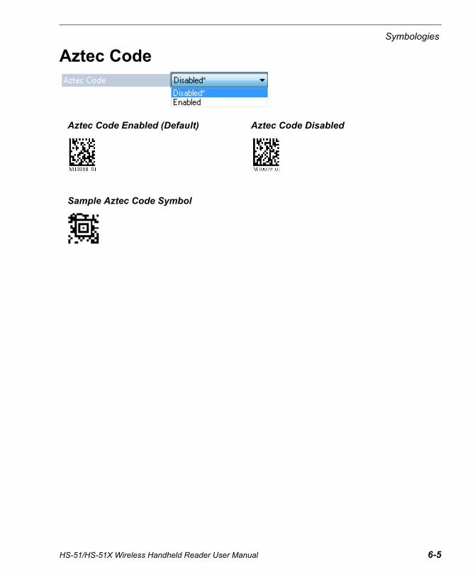
Aztec Code
Aztec Code Enabled (Default) Aztec Code Disabled
Sample Aztec Code Symbol
HS-51/HS-51X Wireless Handheld Reader User Manual 6-5

Code 39
Code 39
Code 39 Disabled Code 39 Enabled (Default)
Code 39 Checksum Enabled Code 39 Checksum Disabled (Default)
Code 39 Checksum Enabled, Strip from Result
Code 39 Extended Code 39 ExtendedFull ASCII Enabled Full ASCII Disabled (Default)
Sample Code 39 Symbol
6-6 HS-51/HS-51X Wireless Handheld Reader User Manual
Symbologies
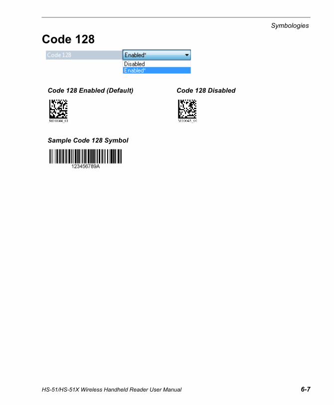
Code 128
Code 128 Enabled (Default) Code 128 Disabled
Sample Code 128 Symbol
HS-51/HS-51X Wireless Handheld Reader User Manual 6-7
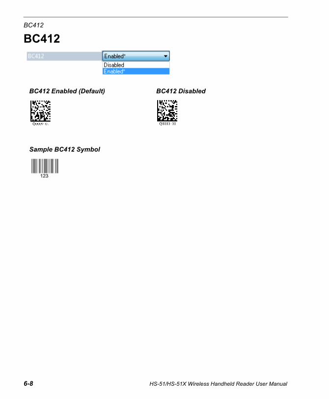
BC412
BC412
BC412 Enabled (Default) BC412 Disabled
Sample BC412 Symbol
6-8 HS-51/HS-51X Wireless Handheld Reader User Manual

Symbologies
Code 93
Code 93 Enabled (Default) Code 93 Disabled
Sample Code 93 Symbol
HS-51/HS-51X Wireless Handheld Reader User Manual 6-9
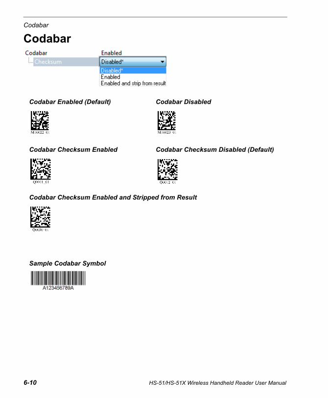
Codabar
Codabar
Codabar Enabled (Default) Codabar Disabled
Codabar Checksum Enabled Codabar Checksum Disabled (Default)
Codabar Checksum Enabled and Stripped from Result
Sample Codabar Symbol
6-10 HS-51/HS-51X Wireless Handheld Reader User Manual
Symbologies
HS-51/HS-51X Wireless Handheld Reader User Manual 6-11
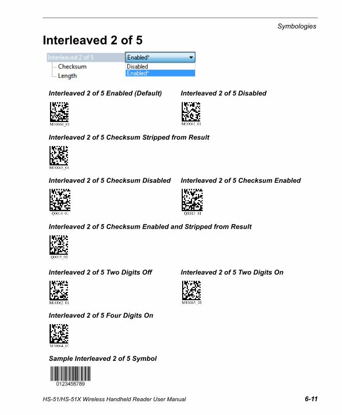
Interleaved 2 of 5
Interleaved 2 of 5 Enabled (Default) Interleaved 2 of 5 Disabled
Interleaved 2 of 5 Checksum Stripped from Result
Interleaved 2 of 5 Checksum Disabled Interleaved 2 of 5 Checksum Enabled
Interleaved 2 of 5 Checksum Enabled and Stripped from Result
Interleaved 2 of 5 Two Digits Off Interleaved 2 of 5 Two Digits On
Interleaved 2 of 5 Four Digits On
Sample Interleaved 2 of 5 Symbol
UPC
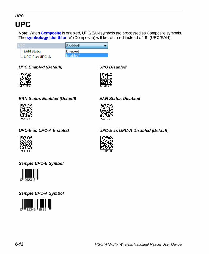
UPCNote: When Composite is enabled, UPC/EAN symbols are processed as Composite symbols. The symbology identifier ‘e’ (Composite) will be returned instead of ‘E’ (UPC/EAN).
UPC Enabled (Default) UPC Disabled
EAN Status Enabled (Default) EAN Status Disabled
UPC-E as UPC-A Enabled UPC-E as UPC-A Disabled (Default)
Sample UPC-E Symbol
Sample UPC-A Symbol
6-12 HS-51/HS-51X Wireless Handheld Reader User Manual
Symbologies
Postal
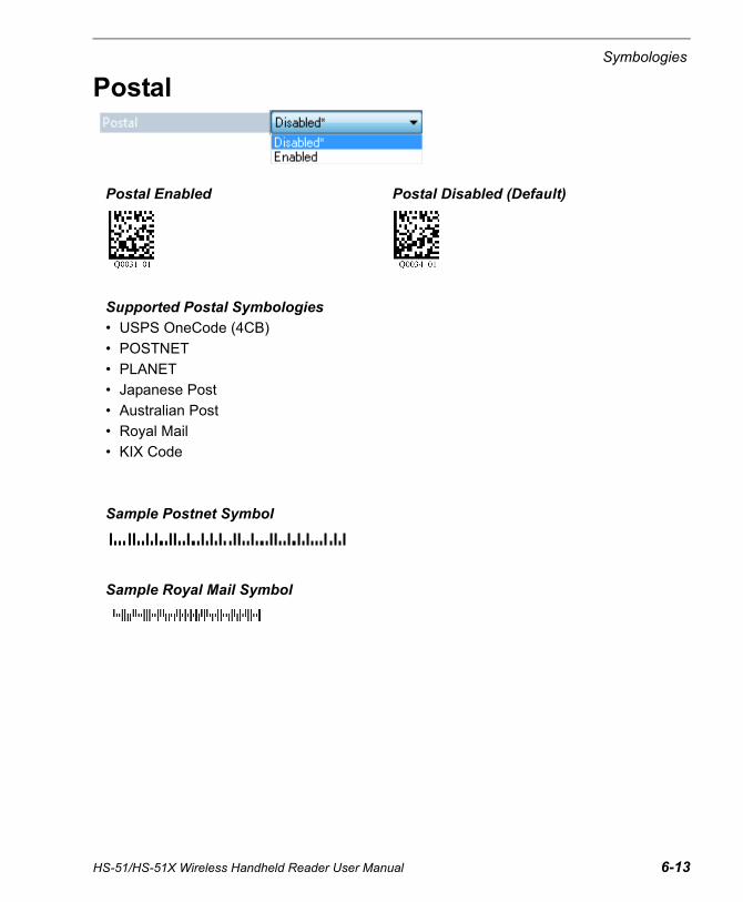
Postal Enabled Postal Disabled (Default)
Supported Postal Symbologies
• USPS OneCode (4CB)
• POSTNET
• PLANET
• Japanese Post
• Australian Post
• Royal Mail
• KIX Code
Sample Postnet Symbol
Sample Royal Mail Symbol
HS-51/HS-51X Wireless Handheld Reader User Manual 6-13

Pharmacode
6-14 HS-51/HS-51X Wireless Handheld Reader User Manual
Pharmacode
Pharmacode Enabled Pharmacode Disabled (Default)
Fixed Symbol Length Enabled Fixed Symbol Length Disabled (Default)
Bar Width Status: Mixed (Default) Bar Width Status: All Narrow
Bar Width Status: All Wide Bar Width Status: Fixed Threshold
Decode Direction: Forward (Default) Decode Direction: Reverse
Symbologies
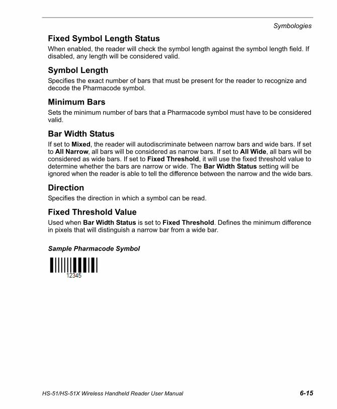
Fixed Symbol Length StatusWhen enabled, the reader will check the symbol length against the symbol length field. If disabled, any length will be considered valid.
Symbol LengthSpecifies the exact number of bars that must be present for the reader to recognize and decode the Pharmacode symbol.
Minimum BarsSets the minimum number of bars that a Pharmacode symbol must have to be considered valid.
Bar Width StatusIf set to Mixed, the reader will autodiscriminate between narrow bars and wide bars. If set to All Narrow, all bars will be considered as narrow bars. If set to All Wide, all bars will be considered as wide bars. If set to Fixed Threshold, it will use the fixed threshold value to determine whether the bars are narrow or wide. The Bar Width Status setting will be ignored when the reader is able to tell the difference between the narrow and the wide bars.
DirectionSpecifies the direction in which a symbol can be read.
Fixed Threshold ValueUsed when Bar Width Status is set to Fixed Threshold. Defines the minimum difference in pixels that will distinguish a narrow bar from a wide bar.
Sample Pharmacode Symbol
HS-51/HS-51X Wireless Handheld Reader User Manual 6-15
GS1 DataBar
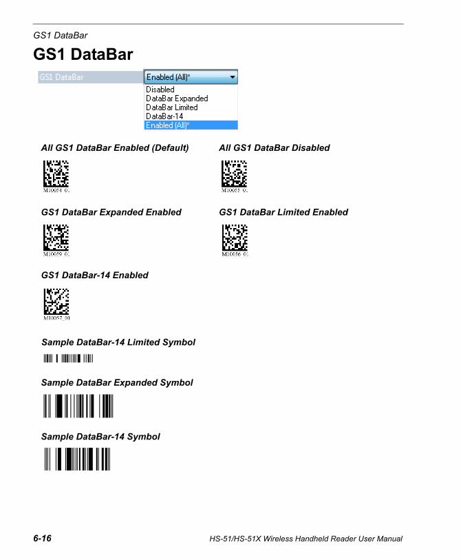
GS1 DataBar
All GS1 DataBar Enabled (Default) All GS1 DataBar Disabled
GS1 DataBar Expanded Enabled GS1 DataBar Limited Enabled
GS1 DataBar-14 Enabled
Sample DataBar-14 Limited Symbol
Sample DataBar Expanded Symbol
Sample DataBar-14 Symbol
6-16 HS-51/HS-51X Wireless Handheld Reader User Manual
Symbologies
PDF417
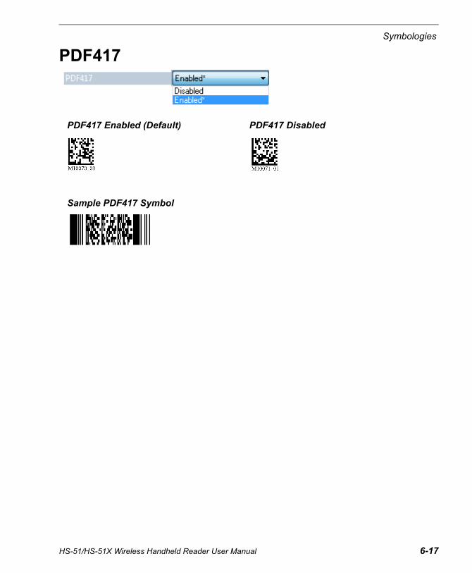
PDF417 Enabled (Default) PDF417 Disabled
Sample PDF417 Symbol
HS-51/HS-51X Wireless Handheld Reader User Manual 6-17
MicroPDF417
MicroPDF417
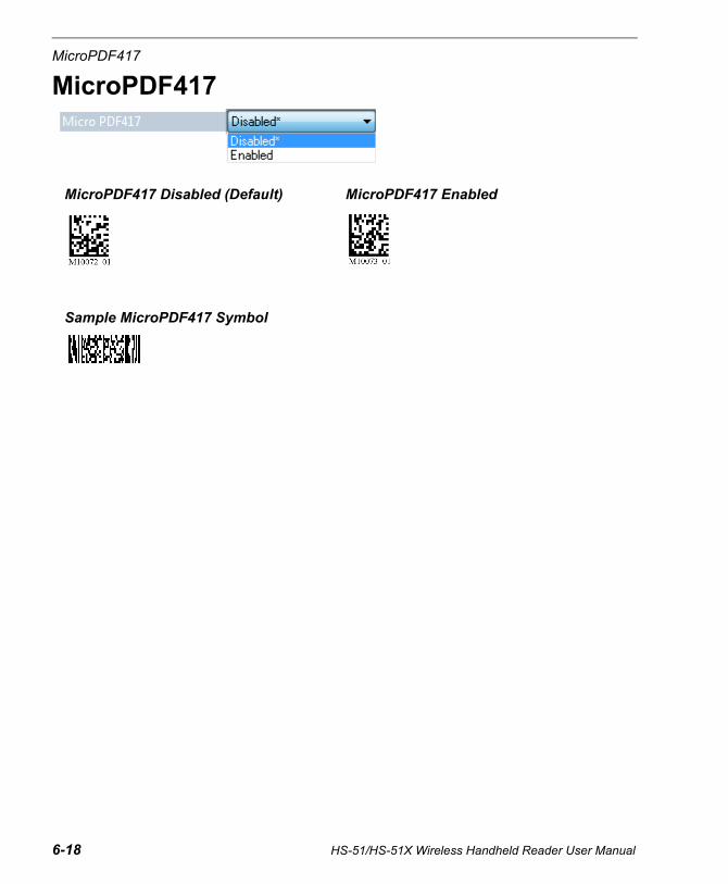
MicroPDF417 Disabled (Default) MicroPDF417 Enabled
Sample MicroPDF417 Symbol
6-18 HS-51/HS-51X Wireless Handheld Reader User Manual
Symbologies
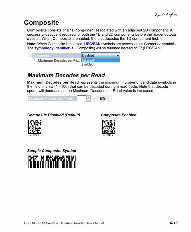
CompositeComposite consists of a 1D component associated with an adjacent 2D component. A successful decode is required for both the 1D and 2D components before the reader outputs a result. When Composite is enabled, the unit decodes the 1D component first.
Note: When Composite is enabled, UPC/EAN symbols are processed as Composite symbols. The symbology identifier ‘e’ (Composite) will be returned instead of ‘E’ (UPC/EAN).
Maximum Decodes per ReadMaximum Decodes per Read represents the maximum number of candidate symbols in the field of view (1 - 100) that can be decoded during a read cycle. Note that decode speed will decrease as the Maximum Decodes per Read value is increased.
Composite Disabled (Default) Composite Enabled
Sample Composite Symbol
HS-51/HS-51X Wireless Handheld Reader User Manual 6-19
Symbology Identifier
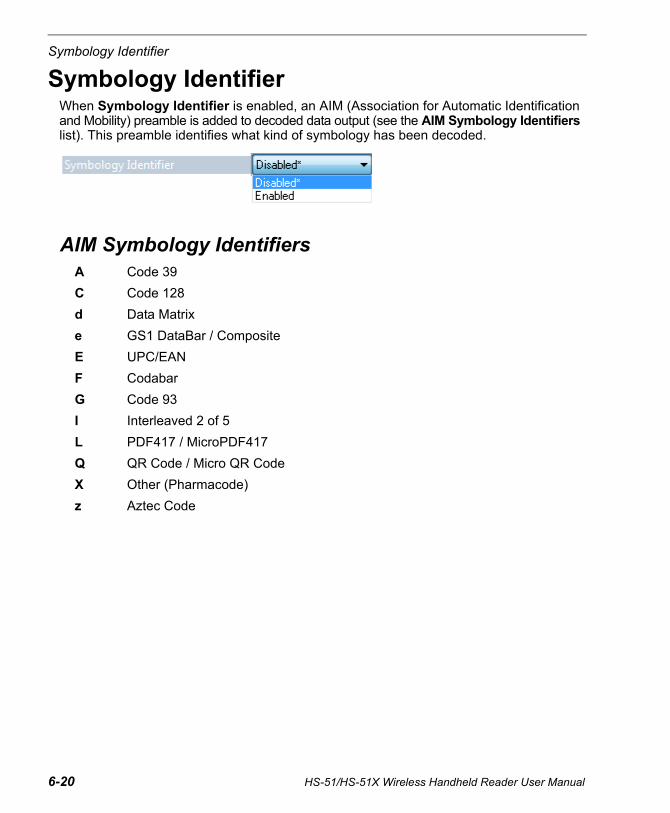
Symbology IdentifierWhen Symbology Identifier is enabled, an AIM (Association for Automatic Identification and Mobility) preamble is added to decoded data output (see the AIM Symbology Identifiers list). This preamble identifies what kind of symbology has been decoded.
AIM Symbology IdentifiersA Code 39
C Code 128
d Data Matrix
e GS1 DataBar / Composite
E UPC/EAN
F Codabar
G Code 93
I Interleaved 2 of 5
L PDF417 / MicroPDF417
Q QR Code / Micro QR Code
X Other (Pharmacode)
z Aztec Code
6-20 HS-51/HS-51X Wireless Handheld Reader User Manual

7 I/O ParametersContents
This section describes how to optimize triggering, and also how to configure the reader’s beep, vibrate, and LED behavior.
ESP can be used to configure reader parameters and then to send and save those parameters to the reader.
You can also configure reader parameters by decoding the Data Matrix symbols in this section.
I/O Parameters by ESP ................................................................................................................ 7-2No Read Notification .................................................................................................................... 7-3Targeting ...................................................................................................................................... 7-4Beep and Vibrate.......................................................................................................................... 7-5Button Stay-Down Time ............................................................................................................... 7-6Button/Trigger Programming ........................................................................................................ 7-7Data Validation ........................................................................................................................... 7-10
HS-51/HS-51X Wireless Handheld Reader User Manual 7-1
I/O Parameters by ESP
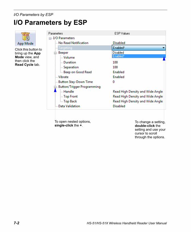
I/O Parameters by ESP
To change a setting, double-click the setting and use your cursor to scroll through the options.
Click this button to bring up the App Mode view, and then click the Read Cycle tab.
To open nested options, single-click the +.
7-2 HS-51/HS-51X Wireless Handheld Reader User Manual
I/O Parameters
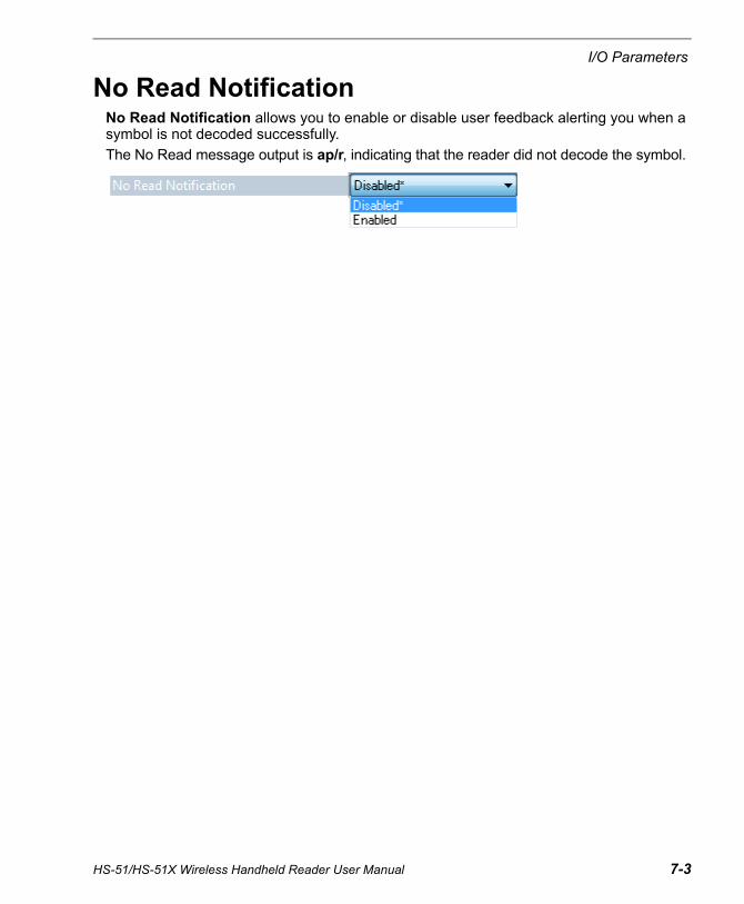
No Read NotificationNo Read Notification allows you to enable or disable user feedback alerting you when a symbol is not decoded successfully.
The No Read message output is ap/r, indicating that the reader did not decode the symbol.
HS-51/HS-51X Wireless Handheld Reader User Manual 7-3

Targeting
7-4 HS-51/HS-51X Wireless Handheld Reader User Manual
TargetingThe Targeting parameter allows you to turn the targeting LEDs on or off. They are on by default.
Read the configuration symbols below to enable or disable Targeting.
Targeting Off Targeting On (Default)

I/O Parameters
HS-51/HS-51X Wireless Handheld Reader User Manual 7-5
Beep and VibrateThe Beep and Vibrate parameters allow you to configure the beep and vibrate behavior of the reader.
Beep and Vibrate are enabled by default. Beep volume is 100% by default.
Read the configuration symbols below to configure Beep and Vibrate.
Beep Parameters in ESP
Vibrate Parameters in ESP
Beep Off, Vibrate OnBeep On, Vibrate On (Default)
Beep On, Vibrate Off Beep Off, Vibrate Off
Beep Volume 0% Beep Volume 33%
Beep Volume 67% Beep Volume 100% (Default)
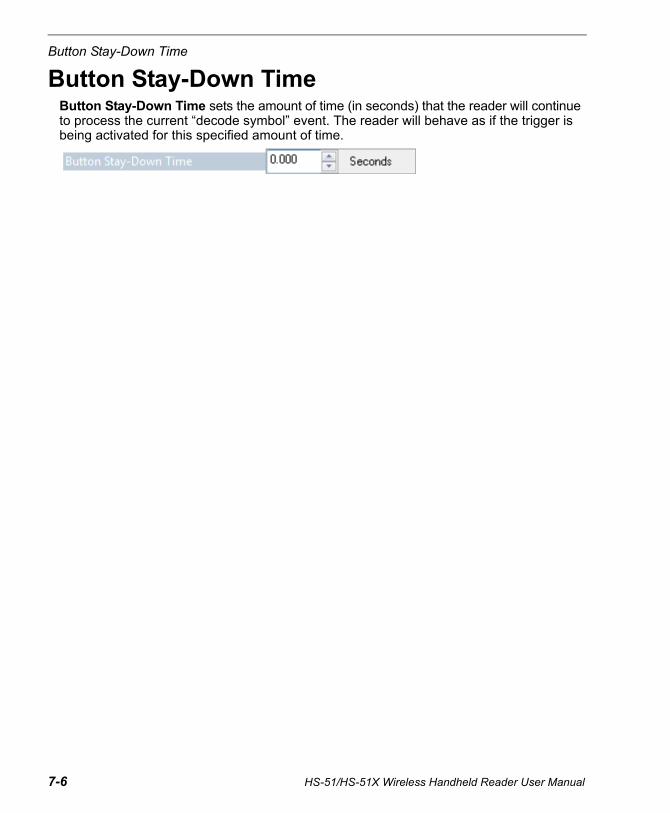
Button Stay-Down Time
Button Stay-Down TimeButton Stay-Down Time sets the amount of time (in seconds) that the reader will continue to process the current “decode symbol” event. The reader will behave as if the trigger is being activated for this specified amount of time.
7-6 HS-51/HS-51X Wireless Handheld Reader User Manual
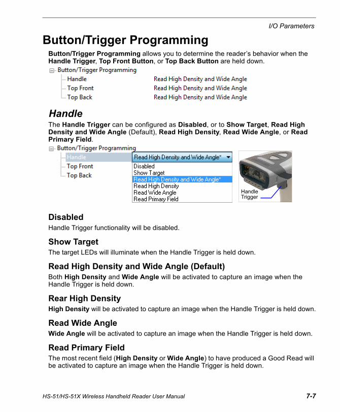
I/O Parameters
HS-51/HS-51X Wireless Handheld Reader User Manual 7-7
Button/Trigger ProgrammingButton/Trigger Programming allows you to determine the reader’s behavior when the Handle Trigger, Top Front Button, or Top Back Button are held down.
HandleThe Handle Trigger can be configured as Disabled, or to Show Target, Read High Density and Wide Angle (Default), Read High Density, Read Wide Angle, or Read Primary Field.
DisabledHandle Trigger functionality will be disabled.
Show TargetThe target LEDs will illuminate when the Handle Trigger is held down.
Read High Density and Wide Angle (Default)Both High Density and Wide Angle will be activated to capture an image when the Handle Trigger is held down.
Rear High DensityHigh Density will be activated to capture an image when the Handle Trigger is held down.
Read Wide AngleWide Angle will be activated to capture an image when the Handle Trigger is held down.
Read Primary FieldThe most recent field (High Density or Wide Angle) to have produced a Good Read will be activated to capture an image when the Handle Trigger is held down.
Handle Trigger

Button/Trigger Programming
Top Front
The Top Front Button can be configured as Disabled, or to Show Target, Read High Density and Wide Angle (Default), Read High Density, Read Wide Angle, or Read Primary Field.
DisabledTop Front Button functionality will be disabled.
Show TargetThe target LEDs will illuminate when the Top Front Button is held down.
Read High Density and Wide Angle (Default)Both High Density and Wide Angle will be activated to capture an image when the Top Front Button is held down.
Rear High DensityHigh Density will be activated to capture an image when the Top Front Button is held down.
Read Wide AngleWide Angle will be activated to capture an image when the Top Front Button is held down.
Read Primary FieldThe most recent field (High Density or Wide Angle) to have produced a Good Read will be activated to capture an image when the Top Front Button is held down.
Top Front Button
7-8 HS-51/HS-51X Wireless Handheld Reader User Manual

I/O Parameters
HS-51/HS-51X Wireless Handheld Reader User Manual 7-9
Top Back
The Top Back Button can be configured as Disabled, or to Show Target, Read High Density and Wide Angle (default), Read High Density, Read Wide Angle, or Read Primary Field.
DisabledTop Back Button functionality will be disabled.
Show TargetThe target LEDs will illuminate when the Top Back Button is held down.
Read High Density and Wide Angle (Default)Both High Density and Wide Angle will be activated to capture an image when the Top Back Button is held down.
Rear High DensityHigh Density will be activated to capture an image when the Top Back Button is held down.
Read Wide AngleWide Angle will be activated to capture an image when the Top Back Button is held down.
Read Primary FieldThe most recent field (High Density or Wide Angle) to have produced a Good Read will be activated to capture an image when the Top Back Button is held down.
Top Back Button
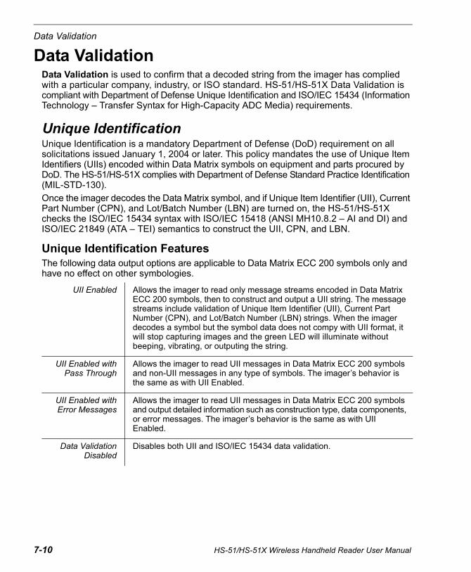
Data Validation
Data ValidationData Validation is used to confirm that a decoded string from the imager has complied with a particular company, industry, or ISO standard. HS-51/HS-51X Data Validation is compliant with Department of Defense Unique Identification and ISO/IEC 15434 (Information Technology – Transfer Syntax for High-Capacity ADC Media) requirements.
Unique IdentificationUnique Identification is a mandatory Department of Defense (DoD) requirement on all solicitations issued January 1, 2004 or later. This policy mandates the use of Unique Item Identifiers (UIIs) encoded within Data Matrix symbols on equipment and parts procured by DoD. The HS-51/HS-51X complies with Department of Defense Standard Practice Identification (MIL-STD-130).
Once the imager decodes the Data Matrix symbol, and if Unique Item Identifier (UII), Current Part Number (CPN), and Lot/Batch Number (LBN) are turned on, the HS-51/HS-51X checks the ISO/IEC 15434 syntax with ISO/IEC 15418 (ANSI MH10.8.2 – AI and DI) and ISO/IEC 21849 (ATA – TEI) semantics to construct the UII, CPN, and LBN.
Unique Identification FeaturesThe following data output options are applicable to Data Matrix ECC 200 symbols only and have no effect on other symbologies.
UII Enabled Allows the imager to read only message streams encoded in Data Matrix ECC 200 symbols, then to construct and output a UII string. The message streams include validation of Unique Item Identifier (UII), Current Part Number (CPN), and Lot/Batch Number (LBN) strings. When the imager decodes a symbol but the symbol data does not compy with UII format, it will stop capturing images and the green LED will illuminate without beeping, vibrating, or outputing the string.
UII Enabled withPass Through
Allows the imager to read UII messages in Data Matrix ECC 200 symbols and non-UII messages in any type of symbols. The imager’s behavior is the same as with UII Enabled.
UII Enabled withError Messages
Allows the imager to read UII messages in Data Matrix ECC 200 symbols and output detailed information such as construction type, data components, or error messages. The imager’s behavior is the same as with UII Enabled.
Data ValidationDisabled
Disables both UII and ISO/IEC 15434 data validation.
7-10 HS-51/HS-51X Wireless Handheld Reader User Manual
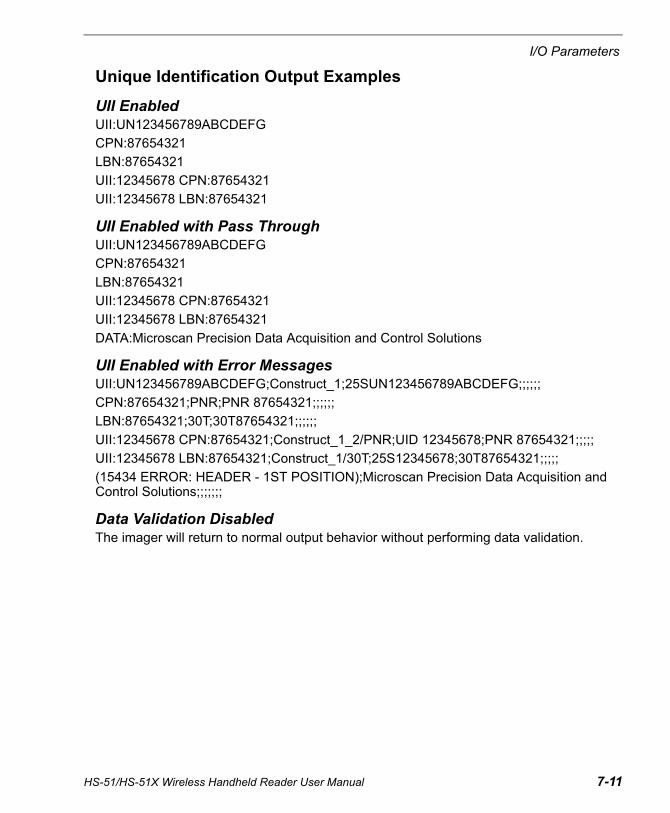
I/O Parameters
Unique Identification Output Examples
UII EnabledUII:UN123456789ABCDEFG
CPN:87654321
LBN:87654321
UII:12345678 CPN:87654321
UII:12345678 LBN:87654321
UII Enabled with Pass ThroughUII:UN123456789ABCDEFG
CPN:87654321
LBN:87654321
UII:12345678 CPN:87654321
UII:12345678 LBN:87654321
DATA:Microscan Precision Data Acquisition and Control Solutions
UII Enabled with Error MessagesUII:UN123456789ABCDEFG;Construct_1;25SUN123456789ABCDEFG;;;;;;
CPN:87654321;PNR;PNR 87654321;;;;;;
LBN:87654321;30T;30T87654321;;;;;;
UII:12345678 CPN:87654321;Construct_1_2/PNR;UID 12345678;PNR 87654321;;;;;
UII:12345678 LBN:87654321;Construct_1/30T;25S12345678;30T87654321;;;;;
(15434 ERROR: HEADER - 1ST POSITION);Microscan Precision Data Acquisition and Control Solutions;;;;;;;
Data Validation DisabledThe imager will return to normal output behavior without performing data validation.
HS-51/HS-51X Wireless Handheld Reader User Manual 7-11
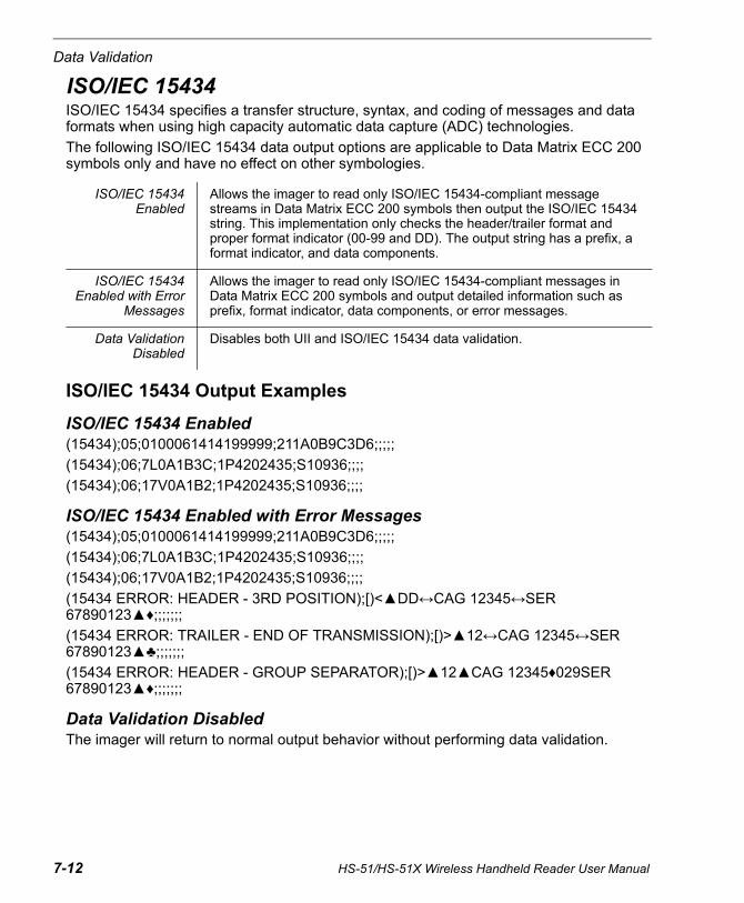
Data Validation
ISO/IEC 15434ISO/IEC 15434 specifies a transfer structure, syntax, and coding of messages and data formats when using high capacity automatic data capture (ADC) technologies.
The following ISO/IEC 15434 data output options are applicable to Data Matrix ECC 200 symbols only and have no effect on other symbologies.
ISO/IEC 15434 Output Examples
ISO/IEC 15434 Enabled(15434);05;0100061414199999;211A0B9C3D6;;;;;
(15434);06;7L0A1B3C;1P4202435;S10936;;;;
(15434);06;17V0A1B2;1P4202435;S10936;;;;
ISO/IEC 15434 Enabled with Error Messages(15434);05;0100061414199999;211A0B9C3D6;;;;;
(15434);06;7L0A1B3C;1P4202435;S10936;;;;
(15434);06;17V0A1B2;1P4202435;S10936;;;;
(15434 ERROR: HEADER - 3RD POSITION);[)<▲DD↔CAG 12345↔SER 67890123▲♦;;;;;;;
(15434 ERROR: TRAILER - END OF TRANSMISSION);[)>▲12↔CAG 12345↔SER 67890123▲♣;;;;;;;
(15434 ERROR: HEADER - GROUP SEPARATOR);[)>▲12▲CAG 12345♦029SER 67890123▲♦;;;;;;;
Data Validation DisabledThe imager will return to normal output behavior without performing data validation.
ISO/IEC 15434Enabled
Allows the imager to read only ISO/IEC 15434-compliant message streams in Data Matrix ECC 200 symbols then output the ISO/IEC 15434 string. This implementation only checks the header/trailer format and proper format indicator (00-99 and DD). The output string has a prefix, a format indicator, and data components.
ISO/IEC 15434Enabled with Error
Messages
Allows the imager to read only ISO/IEC 15434-compliant messages in Data Matrix ECC 200 symbols and output detailed information such as prefix, format indicator, data components, or error messages.
Data ValidationDisabled
Disables both UII and ISO/IEC 15434 data validation.
7-12 HS-51/HS-51X Wireless Handheld Reader User Manual
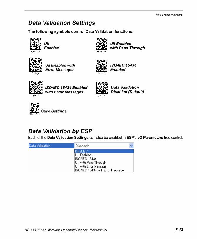
I/O Parameters
Data Validation SettingsThe following symbols control Data Validation functions:
Data Validation by ESPEach of the Data Validation Settings can also be enabled in ESP’s I/O Parameters tree control.
Data Validation Disabled (Default)
Save Settings
UII Enabled with Error Messages
ISO/IEC 15434 Enabled
ISO/IEC 15434 Enabled with Error Messages
UII Enabled
UII Enabled with Pass Through
HS-51/HS-51X Wireless Handheld Reader User Manual 7-13

Data Validation
Detailed Output FormatThe table below describes data validation output in detail.
Note: UII Enabled with Pass Through will add the prefix DATA to non-UII output for all symbologies.
Note: UII Enabled with Error Messages will output the following format: UII/CPN/LBN; DF0; DF1; DF2; DF3; DF4; DF5; DF6; DF7.
Note: When ISO/IEC 15434 output is in compliance with the standard, the format is (15434); DF0; DF1; DF2; DF3; DF4; DF5; DF6; DF7. When it is not in compliance with the standard, the output is (15434 ERROR: xxxx);;;;;;;; where DF0 is the format indicator showing which type of data qualifier is in use.
UII EnabledContent of Decoded Data Matrix Symbol UII/CPN/LBN
Valid UIIUII:UII_dataExample: UII:12345678
Valid CPNValid LBN
CPN:CPN_dataExample: CPN:87654321LBN:LBN_dataExample: LBN:87654321
Valid UII and CPNValid UII and LBN
UII:UII_data CPN:CPN_dataExample: UII:12345678 CPN:87654321UII:UII_data LBN:LBN_dataExample: UII:12345678 LBN:87654321
Valid UII and Invalid CPNValid UII and Invalid LBN
UII:UII_data (CPN ERROR)Example: UII:12345678 (CPN ERROR)UII:UII_data (LBN ERROR)Example: UII:12345678 (LBN ERROR)
Invalid UII and Valid CPNInvalid UII and Valid LBN
(UII ERROR) CPN:CPN_dataExample: (UII ERROR) CPN:87654321(UII ERROR) LBN:LBN_dataExample: (UII ERROR) LBN:87654321
None of the above(Invalid UII; Invalid CPN; Invalid LBN; Invalid UII and Invalid CPN; Invalid UII and Invalid LBN)
No output data
UII Enabled with Error MessagesContent of Decoded Data Matrix Symbol
UII/CPN/LBN DFO
Valid UIIUII:UII_dataExample: UII:12345678
Constructed UII typeExample: Contruct_1
7-14 HS-51/HS-51X Wireless Handheld Reader User Manual
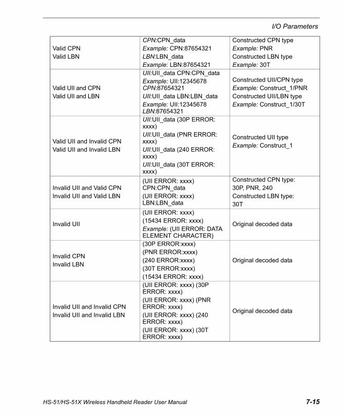
I/O Parameters
Valid CPNValid LBN
CPN:CPN_dataExample: CPN:87654321LBN:LBN_dataExample: LBN:87654321
Constructed CPN typeExample: PNRConstructed LBN typeExample: 30T
Valid UII and CPNValid UII and LBN
UII:UII_data CPN:CPN_dataExample: UII:12345678 CPN:87654321UII:UII_data LBN:LBN_dataExample: UII:12345678 LBN:87654321
Constructed UII/CPN typeExample: Construct_1/PNRConstructed UII/LBN typeExample: Construct_1/30T
Valid UII and Invalid CPNValid UII and Invalid LBN
UII:UII_data (30P ERROR: xxxx)UII:UII_data (PNR ERROR: xxxx)UII:UII_data (240 ERROR: xxxx)UII:UII_data (30T ERROR: xxxx)
Constructed UII typeExample: Construct_1
Invalid UII and Valid CPNInvalid UII and Valid LBN
(UII ERROR: xxxx) CPN:CPN_data(UII ERROR: xxxx) LBN:LBN_data
Constructed CPN type:30P, PNR, 240Constructed LBN type:30T
Invalid UII
(UII ERROR: xxxx)(15434 ERROR: xxxx)Example: (UII ERROR: DATA ELEMENT CHARACTER)
Original decoded data
Invalid CPNInvalid LBN
(30P ERROR:xxxx)(PNR ERROR:xxxx)(240 ERROR:xxxx)(30T ERROR:xxxx)(15434 ERROR: xxxx)
Original decoded data
Invalid UII and Invalid CPNInvalid UII and Invalid LBN
(UII ERROR: xxxx) (30P ERROR: xxxx)(UII ERROR: xxxx) (PNR ERROR: xxxx)(UII ERROR: xxxx) (240 ERROR: xxxx)(UII ERROR: xxxx) (30T ERROR: xxxx)
Original decoded data
HS-51/HS-51X Wireless Handheld Reader User Manual 7-15
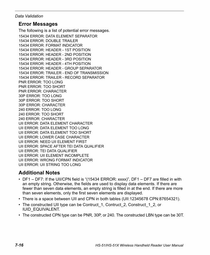
Data Validation
Error MessagesThe following is a list of potential error messages.15434 ERROR: DATA ELEMENT SEPARATOR15434 ERROR: DOUBLE TRAILER15434 ERROR: FORMAT INDICATOR15434 ERROR: HEADER - 1ST POSITION15434 ERROR: HEADER - 2ND POSITION15434 ERROR: HEADER - 3RD POSITION15434 ERROR: HEADER - 4TH POSITION15434 ERROR: HEADER - GROUP SEPARATOR15434 ERROR: TRAILER - END OF TRANSMISSION15434 ERROR: TRAILER - RECORD SEPARATORPNR ERROR: TOO LONGPNR ERROR: TOO SHORTPNR ERROR: CHARACTER30P ERROR: TOO LONG30P ERROR: TOO SHORT30P ERROR: CHARACTER240 ERROR: TOO LONG240 ERROR: TOO SHORT240 ERROR: CHARACTERUII ERROR: DATA ELEMENT CHARACTERUII ERROR: DATA ELEMENT TOO LONGUII ERROR: DATA ELEMENT TOO SHORTUII ERROR: LOWER CASE CHARACTERUII ERROR: NEED UII ELEMENT FIRSTUII ERROR: SPACE AFTER TEI DATA QUALIFIERUII ERROR: TEI DATA QUALIFIERUII ERROR: UII ELEMENT INCOMPLETEUII ERROR: WRONG FORMAT INDICATORUII ERROR: UII STRING TOO LONG
Additional Notes• DF1 – DF7: If the UII/CPN field is “(15434 ERROR: xxxx)”, DF1 – DF7 are filled in with
an empty string. Otherwise, the fields are used to display data elements. If there are fewer than seven data elements, an empty string is filled in at the end. If there are more than seven elements, only the first seven elements are displayed.
• There is a space between UII and CPN in both tables (UII:12345678 CPN:87654321).
• The constructed UII type can be Contruct_1, Contruct_2, Construct_1_2, or IUID_EQUIVALENT.
• The constructed CPN type can be PNR, 30P, or 240. The constructed LBN type can be 30T.
7-16 HS-51/HS-51X Wireless Handheld Reader User Manual

8 Advanced OperationsContents
This section describes settings that can be configured to speed up processing or to improve symbol readability in various circumstances. You will also find information about how to pair a Bluetooth Keyboard with operating systems and wireless devices.
ESP can be used to configure reader parameters and then to send and save those parameters to the reader.
You can also configure reader parameters by decoding the Data Matrix symbols in this section.
Continuous Read.......................................................................................................................... 8-2Mirroring ....................................................................................................................................... 8-3Bluetooth Keyboard-to-Windows 7 Pairing ................................................................................... 8-4Bluetooth Keyboard-to-Tablet Pairing........................................................................................... 8-8Bluetooth Keyboard-to-Mobile Phone Pairing............................................................................. 8-11Reader Paging............................................................................................................................ 8-13Bluetooth Out-of-Range Notification........................................................................................... 8-14Cell Phone Reading Enhancement ............................................................................................ 8-15
HS-51/HS-51X Wireless Handheld Reader User Manual 8-1

Continuous Read
Continuous ReadRead the following symbols to enable or disable Continuous Read.
Continuous Read On Continuous Read Off (Default)
8-2 HS-51/HS-51X Wireless Handheld Reader User Manual
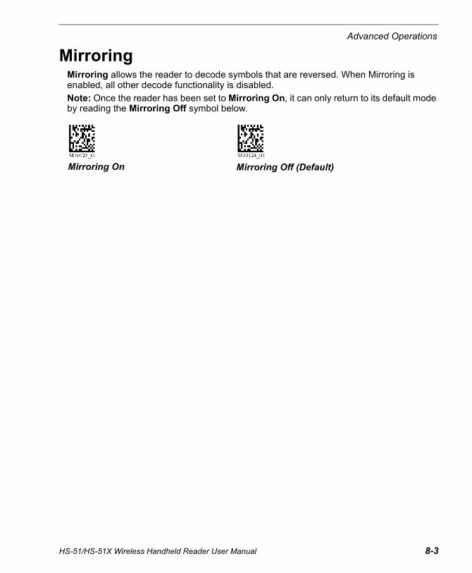
Advanced Operations
MirroringMirroring allows the reader to decode symbols that are reversed. When Mirroring is enabled, all other decode functionality is disabled.
Note: Once the reader has been set to Mirroring On, it can only return to its default mode by reading the Mirroring Off symbol below.
Mirroring On Mirroring Off (Default)
HS-51/HS-51X Wireless Handheld Reader User Manual 8-3
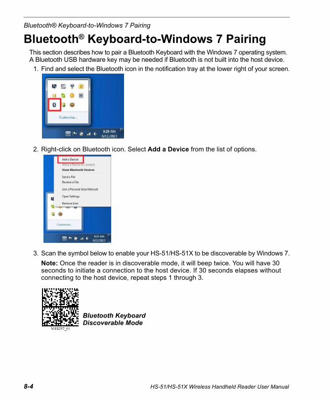
Bluetooth® Keyboard-to-Windows 7 Pairing
8-4 HS-51/HS-51X Wireless Handheld Reader User Manual
Bluetooth® Keyboard-to-Windows 7 PairingThis section describes how to pair a Bluetooth Keyboard with the Windows 7 operating system. A Bluetooth USB hardware key may be needed if Bluetooth is not built into the host device.
1. Find and select the Bluetooth icon in the notification tray at the lower right of your screen.
2. Right-click on Bluetooth icon. Select Add a Device from the list of options.
3. Scan the symbol below to enable your HS-51/HS-51X to be discoverable by Windows 7.
Note: Once the reader is in discoverable mode, it will beep twice. You will have 30 seconds to initiate a connection to the host device. If 30 seconds elapses without connecting to the host device, repeat steps 1 through 3.
Bluetooth Keyboard Discoverable Mode

Advanced Operations
HS-51/HS-51X Wireless Handheld Reader User Manual 8-5
4. You will see the HS-51/HS-51X as a device option in the Add a Device window. Select the HS-51/HS-51X.
5. Once the HS-51/HS-51X has been selected, a screen will appear containing a PIN.

Bluetooth® Keyboard-to-Windows 7 Pairing
8-6 HS-51/HS-51X Wireless Handheld Reader User Manual
6. When the reader beeps twice, it is ready for the entry of the PIN. Using the Bluetooth Keyboard-to-Windows 7 Pin Reference Codes, scan each of the PIN digits with your HS-51/HS-51X. You will have 30 seconds to enter the PIN. Scan the Submit PIN symbol after the pin sequence has been entered.
Note: Failure to complete PIN entry in the allotted 30 seconds will result in the appearance of a Try Again button. Click the Try Again button and repeat steps 3 through 6.
7. Once the installation of the HS-51/HS-51X driver is completed, and if the pin was entered correctly, a This device has been successfully added to this computer window will appear.
8. The reader will beep once and the wireless icon LED will remain solid when the reader is successfully connected.
9. To test the connection, open WIndows 7 Notepad and scan a series of symbols. If data appears in Notepad after each scan, you have successfully connected to Windows 7. If Notepad is not showing scanned data, remove the Bluetooth device from the Bluetooth device screen and repeat steps 1 through 7.
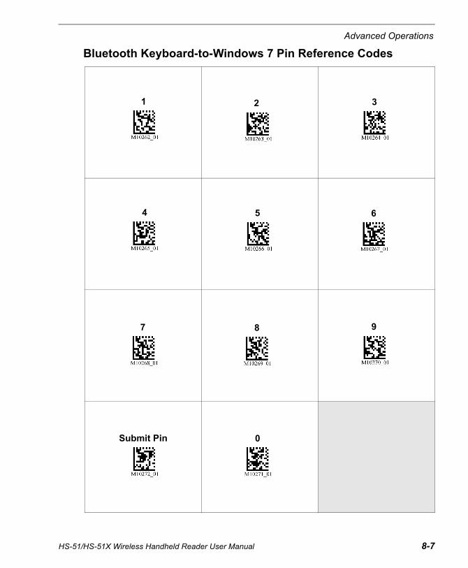
Advanced Operations
Bluetooth Keyboard-to-Windows 7 Pin Reference Codes
1 2 3
4 5 6
7 8 9
Submit Pin 0
HS-51/HS-51X Wireless Handheld Reader User Manual 8-7

Bluetooth® Keyboard-to-Tablet Pairing
8-8 HS-51/HS-51X Wireless Handheld Reader User Manual
Bluetooth® Keyboard-to-Tablet PairingThis section describes how to pair a Bluetooth Keyboard with a tablet device. The HS-51/HS-51X is compatible with most tablets.
1. In your tablet device’s list of applications, select the Settings icon.
2. Select the Bluetooth setting.
3. Scan the following symbol to enable the HS-51/HS-51X to be discoverable by the tablet.
4. Once the reader is in discoverable mode, it will beep twice. You will have 30 seconds to initiate a connection to the host device. If 30 seconds elapses without connecting to the host device, scan the discoverable mode symbol again.
5. The HS-51/HS-51X will appear on the list of Bluetooth devices on the tablet. Select the reader to initiate connection.
6. A window with a PIN will appear on the tablet.
7. Once the reader beeps twice, it is ready for you to enter the PIN. Using the Bluetooth Keyboard-to-Tablet Pin Reference Codes, scan each of the PIN digits with your reader. You will have 30 seconds to enter the PIN. Scan the Submit PIN symbol when the pin sequence has been entered.
8. The tablet will show a positive connection indicator when the connection is completed. The HS-51/HS-51X will beep once when connected and the wireless icon LED will remain solid.
Bluetooth Keyboard Discoverable Mode
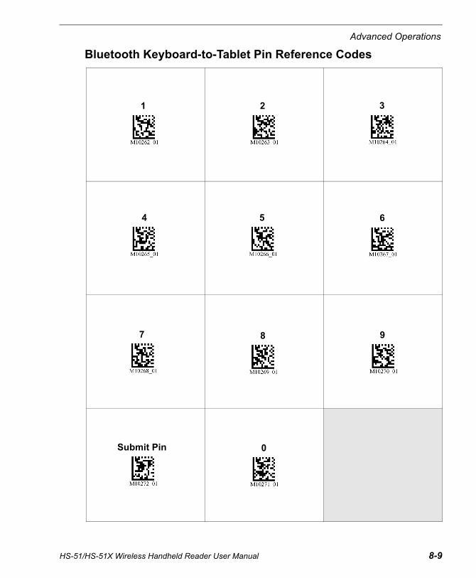
Advanced Operations
Bluetooth Keyboard-to-Tablet Pin Reference Codes
1 2 3
4 5 6
7 8 9
Submit Pin 0
HS-51/HS-51X Wireless Handheld Reader User Manual 8-9

Bluetooth® Keyboard-to-Tablet Pairing
Keyboard Display Options or Apple iOSImportant: Keyboard Display Options are only compatible with Apple iOS.
To configure the bottom button on the reader to toggle the host device’s on-screen keyboard, scan the following symbol:
To reset the bottom button to the default setting, scan the following symbol:
Re-connect to Other Bluetooth DevicesTo re-establish connection to another host device already paired with the reader, scan the following symbol:
The reader will appear in the list of devices in the Bluetooth menu. Select the reader to initiate the connection.
Note: If the reader’s battery has been removed, the reader is out of range (beyond the working range of 10 meters/30 feet), or the reader is powered off while in default connection settings, the reader will initiate connection to the most recent host device when back in service.
Clear Connection HistoryDecode the Clear Bluetooth Connections symbol below to clear previous Bluetooth addresses from the reader’s memory. Then decode the Reboot Reader symbol.
Note: This command does not automatically remove the reader from the list of devices in the Bluetooth menu. You must delete the reader from the list.
To clear connection information fom all Bluetooth Keyboard hosts, scan the following symbol:
Note: To re-establish a connection once the connection history has been cleared, repeat steps 1 through 8.
Keyboard Display Options On
Keyboard Display Options Off
Switch Host Device
Clear Bluetooth Connection
Reboot Reader
8-10 HS-51/HS-51X Wireless Handheld Reader User Manual
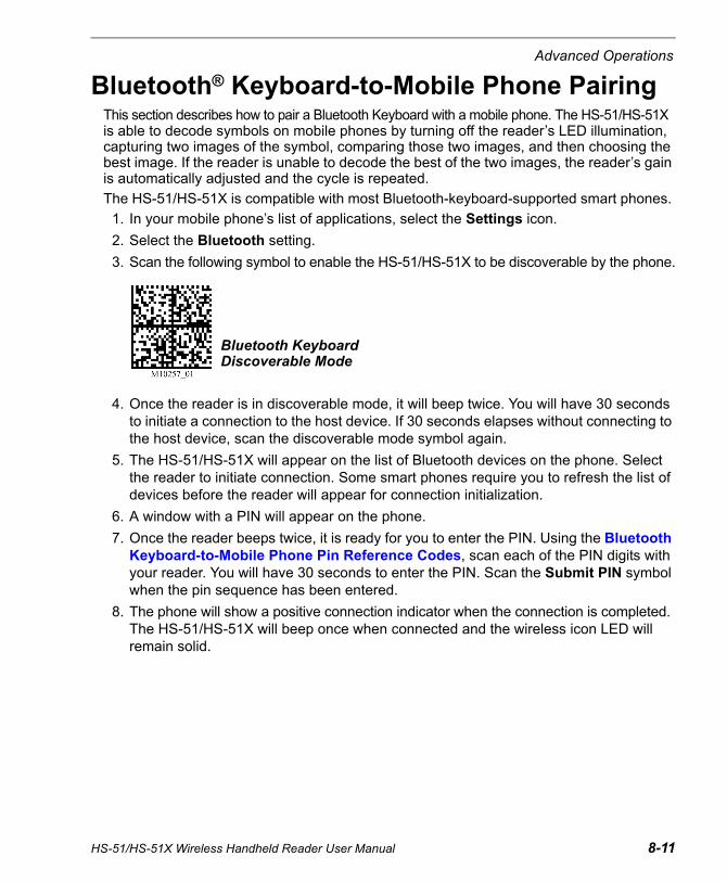
Advanced Operations
HS-51/HS-51X Wireless Handheld Reader User Manual 8-11
Bluetooth® Keyboard-to-Mobile Phone PairingThis section describes how to pair a Bluetooth Keyboard with a mobile phone. The HS-51/HS-51X is able to decode symbols on mobile phones by turning off the reader’s LED illumination, capturing two images of the symbol, comparing those two images, and then choosing the best image. If the reader is unable to decode the best of the two images, the reader’s gain is automatically adjusted and the cycle is repeated.
The HS-51/HS-51X is compatible with most Bluetooth-keyboard-supported smart phones.
1. In your mobile phone’s list of applications, select the Settings icon.
2. Select the Bluetooth setting.
3. Scan the following symbol to enable the HS-51/HS-51X to be discoverable by the phone.
4. Once the reader is in discoverable mode, it will beep twice. You will have 30 seconds to initiate a connection to the host device. If 30 seconds elapses without connecting to the host device, scan the discoverable mode symbol again.
5. The HS-51/HS-51X will appear on the list of Bluetooth devices on the phone. Select the reader to initiate connection. Some smart phones require you to refresh the list of devices before the reader will appear for connection initialization.
6. A window with a PIN will appear on the phone.
7. Once the reader beeps twice, it is ready for you to enter the PIN. Using the Bluetooth Keyboard-to-Mobile Phone Pin Reference Codes, scan each of the PIN digits with your reader. You will have 30 seconds to enter the PIN. Scan the Submit PIN symbol when the pin sequence has been entered.
8. The phone will show a positive connection indicator when the connection is completed. The HS-51/HS-51X will beep once when connected and the wireless icon LED will remain solid.
Bluetooth Keyboard Discoverable Mode
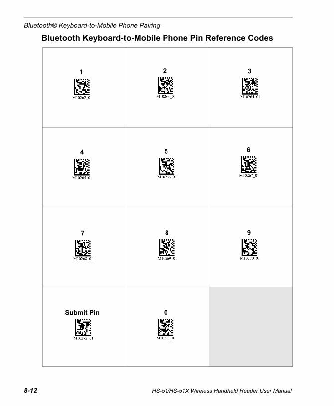
Bluetooth® Keyboard-to-Mobile Phone Pairing
8-12 HS-51/HS-51X Wireless Handheld Reader User Manual
Bluetooth Keyboard-to-Mobile Phone Pin Reference Codes
1 2 3
4 5 6
7 8 9
Submit Pin 0
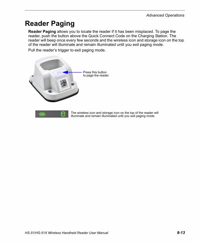
Advanced Operations
HS-51/HS-51X Wireless Handheld Reader User Manual 8-13
Reader PagingReader Paging allows you to locate the reader if it has been misplaced. To page the reader, push the button above the Quick Connect Code on the Charging Station. The reader will beep once every few seconds and the wireless icon and storage icon on the top of the reader will illuminate and remain illuminated until you exit paging mode.
Pull the reader’s trigger to exit paging mode.
Press this button to page the reader.
The wireless icon and storage icon on the top of the reader will illuminate and remain illuminated until you exit paging mode.

Bluetooth® Out-of-Range Notification
8-14 HS-51/HS-51X Wireless Handheld Reader User Manual
Bluetooth® Out-of-Range NotificationBluetooth Out-of-Range Notification indicates when the reader is out of range and no longer communicating with the modem. The typical working range is 10 meters (30 feet).
The configuration symbols below allow you to configure the reader’s out-of-range indicators. The wireless LED will flash by default when the reader is out-of-range.
Bluetooth Out-of-Range Beep Only – On
Bluetooth Out-of-Range Vibrate Only – On
Bluetooth Out-of-Range Beep and Vibrate – On
Bluetooth Out-of-Range Beep and Vibrate – Off
Advanced Operations
HS-51/HS-51X Wireless Handheld Reader User Manual 8-15
Cell Phone Reading EnhancementCell Phone Reading Enhancement improves the reader’s ability to decode symbols on smart phone and tablet screens as well as most PC monitors.
When the reader is in this mode, LED illumination is turned off, two images are captured and compared, and the symbol in the better of the two images is decoded. If the better of the two images results in a No Read, the reader automatically adjusts gain settings and the cycle is repeated.
Cell Phone Reading Enhancement On
Cell Phone Reading Enhancement Off

Cell Phone Reading Enhancement
8-16 HS-51/HS-51X Wireless Handheld Reader User Manual
9 TerminalContents
This section describes the Terminal interface and macro functions in ESP.
Terminal View................................................................................................................................9-2Find ...............................................................................................................................................9-3Send..............................................................................................................................................9-4Macros...........................................................................................................................................9-5Terminal Right-Click Menu............................................................................................................9-6Terminal Dropdown Menu.............................................................................................................9-7
HS-51/HS-51X Wireless Handheld Reader User Manual 9-1

Terminal View
Terminal ViewClick the Terminal button.
You will see the following view:
The Terminal interface allows you to send commands to the reader by using macros, by copying and pasting, or by typing commands in the Send text field.
The Terminal view also displays symbol data or information from the reader.
You can also right click on the Terminal screen to bring up a menu of further options.
Click on desired macro to run.
Click on Macros arrow to Add Macro, Remove Macro, or Edit Macro.
Macros listed on this bar.
Terminal screen
Type text here to find matching text in the terminal window.
Type text commands here.
Clear screen, copy, paste, save.
9-2 HS-51/HS-51X Wireless Handheld Reader User Manual

Terminal
FindThe Find function allows you to enter text strings to be searched for in the terminal window. For example, suppose a series of symbols have been scanned into the terminal view and you want to determine if a particular symbol whose data begins with “ABC” has been read.
1. Type “ABC” into the Find box.
2. Press Enter.
The first instance of “ABC” will be highlighted in the terminal window.
3. Click the Find button to the left of the text field to locate additional instances of “ABC”.
HS-51/HS-51X Wireless Handheld Reader User Manual 9-3

Send
SendThe Send function allows you to enter text commands and then send them to the reader. (See Text Commands.)
For example, suppose you want to disable the vibrate function in the reader. To disable vibrate using a text command, you would enter “P%A10” (the command that disables vibrate) in the text field and click Send.
Once text commands are initiated, they are saved in a dropdown menu that can be accessed by clicking the arrow to the right of the text field.
You can also send the current command repeatedly by clicking the Send button repeatedly.
Type text commands in the text field and then click the Send button to initiate. Clicking Send repeatedly will initiate the command repeatedly.
Click here to access the dropdown menu of stored text commands.
9-4 HS-51/HS-51X Wireless Handheld Reader User Manual
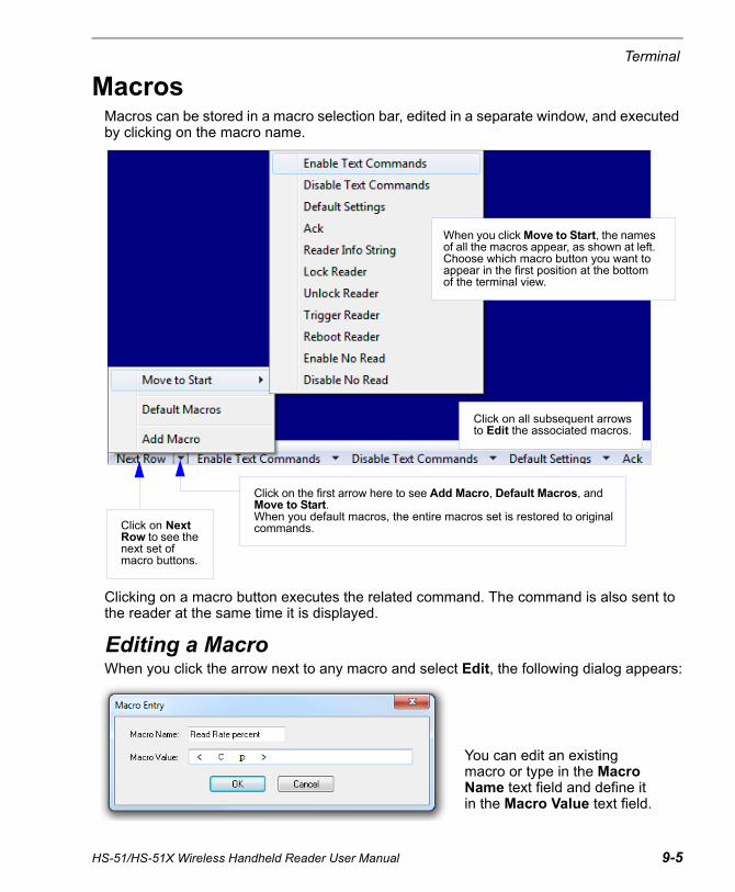
Terminal
MacrosMacros can be stored in a macro selection bar, edited in a separate window, and executed by clicking on the macro name.
Clicking on a macro button executes the related command. The command is also sent to the reader at the same time it is displayed.
Editing a MacroWhen you click the arrow next to any macro and select Edit, the following dialog appears:
Click on the first arrow here to see Add Macro, Default Macros, and Move to Start.When you default macros, the entire macros set is restored to original commands.Click on Next
Row to see the next set of macro buttons.
Click on all subsequent arrows to Edit the associated macros.
When you click Move to Start, the names of all the macros appear, as shown at left. Choose which macro button you want to appear in the first position at the bottom of the terminal view.
You can edit an existing macro or type in the Macro Name text field and define it in the Macro Value text field.
HS-51/HS-51X Wireless Handheld Reader User Manual 9-5

Terminal Right-Click Menu
Terminal Right-Click MenuRight click in the terminal window to display the following menu:
Function KeysThe Function Keys dialog allows you to assign commands to specific function keys on a standard keyboard. Note that the F1 key is reserved for opening ESP Help, and the F3 key is reserved for the Find Next function.
Note: This feature is also available from the Terminal Dropdown Menu and the Terminal tab of the Preferences dialog.
• Copy selected text to clipboard.
• Paste from terminal or other text.
• Clear all text in terminal window.
• Select All text in the terminal window.
• Save... incoming and outgoing data into a text file.
• Change Font... of data received from the reader.
• Change Echo Font... to change the appearance of user-entered data.
• Disable Echo to hide user-entered data.
• Change Background Color of the terminal window.
• Non-Printable Characters can be shown or hidden in the terminal view in Standard or Enhanced format.
• Default Settings to return all of the above to original settings.
• Keyboard Macros brings up the Function Keys dialog, which allows you to create customized macro functions.
Select the desired function key and then enter your macro keystrokes in the associated key map. For example, to make Ctrl-F2 the keystroke to send a trigger character, select F2, then in the Ctrl text field, enter <trigger character> and click OK. Then whenever Ctrl-F2 is keyed, the trigger character will start the read cycle.
9-6 HS-51/HS-51X Wireless Handheld Reader User Manual
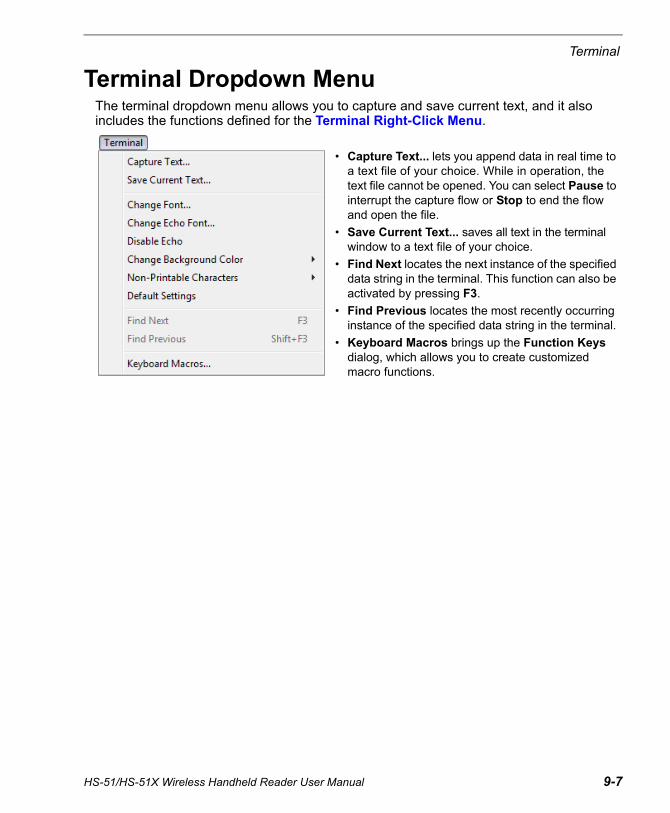
Terminal
Terminal Dropdown MenuThe terminal dropdown menu allows you to capture and save current text, and it also includes the functions defined for the Terminal Right-Click Menu.
• Capture Text... lets you append data in real time to a text file of your choice. While in operation, the text file cannot be opened. You can select Pause to interrupt the capture flow or Stop to end the flow and open the file.
• Save Current Text... saves all text in the terminal window to a text file of your choice.
• Find Next locates the next instance of the specified data string in the terminal. This function can also be activated by pressing F3.
• Find Previous locates the most recently occurring instance of the specified data string in the terminal.
• Keyboard Macros brings up the Function Keys dialog, which allows you to create customized macro functions.
HS-51/HS-51X Wireless Handheld Reader User Manual 9-7

Terminal Dropdown Menu
9-8 HS-51/HS-51X Wireless Handheld Reader User Manual

10 Utilities Contents
This section explains ESP’s Utilities features. These include Differences from Default, which shows all currently enabled reader settings that are not default settings; Firmware, where you can update and verify your reader’s firmware; Bluetooth, which allows you to create custom Quick Connect Codes; and Advanced, which allows you to collect batch files for customized reader configuration and optimization.
Differences from Default............................................................................................................. 10-2Firmware .................................................................................................................................... 10-3Bluetooth .................................................................................................................................... 10-5Advanced ................................................................................................................................... 10-6
HS-51/HS-51X Wireless Handheld Reader User Manual 10-1

Differences from Default
10-2 HS-51/HS-51X Wireless Handheld Reader User Manual
Differences from DefaultClicking the Differences from Default button will cause ESP to check all stored configuration settings and compare them to default settings. All settings that are different than default will appear in the left column (shown below), and descriptions of those settings will appear in the right column.
• To save the Differences from Default report, either as plain text or as a tab-delimited text file, click Save As.
• Click Send and Save to send the settings to the reader and save them, or Send to Reader to send the settings without saving them.
Important: The use the Differences from Default feature, you must connect to the reader and Receive Reader Settings via the Send/Recv button on the toolbar.
Click this button for a list of ESP configuration settings that are different than default settings.
Send configuration settings to the reader without saving by clicking Send to Reader.
Click Save As to save the report as plain text or a tab-delimited text file.
Send configuration settings to the reader and save in ESP by clicking Send and Save.
Click this button to generate a symbol encoded with the commands in the Differences window.

Utilities
HS-51/HS-51X Wireless Handheld Reader User Manual 10-3
FirmwareThe Firmware view in ESP Utilities is a simple way to update and verify your reader’s firmware and to update batch files.
Choose App Code from the Firmware Update dropdown menu and click Start to install new firmware.
The Firmware Verification tool sends a direct query to the reader for its Application Code Version, Firmware Version, Boot Code Version, and Radio Version.
Use this dropdown menu to locate batch files in the host computer’s file directory. Download the needed files directly to the reader by clicking the Start button.
Note: The versions shown here are examples only. App Code, Firmware, and Boot versions may vary.
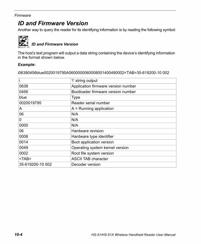
Firmware
ID and Firmware VersionAnother way to query the reader for its identifying information is by reading the following symbol:
The host’s text program will output a data string containing the device’s identifying information in the format shown below.
Example:
i06380456blue0020019795A0600000060008001400490002<TAB>35-619200-10 002
i ‘I’ string output
0638 Application firmware version number
0456 Bootloader firmware version number
blue Type
0020019795 Reader serial number
A A = Running application
06 N/A
0 N/A
0000 N/A
06 Hardware revision
0008 Hardware type identifier
0014 Boot application version
0049 Operating system kernel version
0002 Root file system version
<TAB> ASCII TAB character
35-619200-10 002 Decoder version
ID and Firmware Version
10-4 HS-51/HS-51X Wireless Handheld Reader User Manual
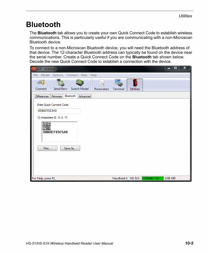
Utilities
BluetoothThe Bluetooth tab allows you to create your own Quick Connect Code to establish wireless communications. This is particularly useful if you are communicating with a non-Microscan Bluetooth device.
To connect to a non-Microscan Bluetooth device, you will need the Bluetooth address of that device. The 12-character Bluetooth address can typically be found on the device near the serial number. Create a Quick Connect Code on the Bluetooth tab shown below. Decode the new Quick Connect Code to establish a connection with the device.
HS-51/HS-51X Wireless Handheld Reader User Manual 10-5

10-6 HS-51/HS-51X Wireless Handheld Reader User Manual
Advanced
AdvancedThe Advanced tab in Utilities features an archive of all batch files containing reader configuration commands. Each batch file’s extension is .crb, and each file contains the fundamental code for programming the reader. Notice that the names of the batch files correspond with the numbers beneath all the Data Matrix configuration symbols.
This tool allows you to use the batch file data to create your own symbols, or to collect only the files that you use frequently to configure the reader for your application.
The Download Collection and Save Collection As... buttons allow you to acquire the entire contents of the batch file archive and save the files in a location of your choice.
Scroll through the list of batch files in the archive and choose the ones you need. Move them to the collection window using the Add arrow. Files can also be transferred by clicking and dragging.The single Remove arrow functions in the same way as the Add arrow, except that it transfers files back to the batch archive. The double Remove arrow allows you to transfer all files simultaneously.
HS-51/HS-51X Wireless Handheld Reader User Manual A-1
AppendicesContents
Appendix A General Specifications .............................................................................................. A-2Appendix B Electrical Specifications ............................................................................................ A-5Appendix C Configuration Symbols.............................................................................................. A-6Appendix D Communications Protocol....................................................................................... A-18Appendix E ASCII Table............................................................................................................. A-19Appendix F Maintenance............................................................................................................ A-20Appendix G Glossary of Terms .................................................................................................. A-21

A-2 HS-51/HS-51X Wireless Handheld Reader User Manual
General Specifications
Appendix A — General SpecificationsMechanical
EnvironmentalEnclosure: IP54 ratedOperating temperature: –20° to 55°C(–4° to 131°F)Storage temperature: –30° to 65° C(–22° to 150°F)Humidity: 5 to 95% (non-condensing)Shock: Withstands multiple drops of 6’ (1.8 meters) to concrete
CE StandardsImmunity: EN 55024ESD: EN 61000-4-2 Radiated RF: EN 61000-4-3Keyed Carrier: ENV50204EFT: EN 61000-4-4Conducted RF: EN 61000-4-6Emissions: EN 55022, Class B Radiated, Class B ConductedEN 60950-1:2006/A11:2009/A1:2010IEC 60825-1: 2007EN 62471:2008
Symbologies2D Symbologies: Data Matrix, QR Code, Micro QR Code, Aztec CodeStacked 1D Symbologies: PDF417, MicroPDF417, GS1 Composite 1D Symbologies: UPC, Code 39, Code 93, Code 128, Interleaved 2 of 5, Codabar, GS1 DataBar, Postal, Pharmacode, BC412
Light Collection OptionsSensor: CMOS 1.2 Megapixel grayscaleSensor Array: 1280 by 960Field Selection: High Density or Wide AngleField of View: High Density: 30° horizontal by 20° vertical; Wide Angle: 50° horizontal by 33.5° verticalFocal Point: Approximately 100 mmOptical Resolution: High Density: 960 x 640; Wide Angle: 960 x 640
Communication ProtocolsInterfaces: USB 2.0 (USB Native HID, USB Keyboard), Bluetooth (Class II) with working range of 10 meters (30 feet), Virtual COM (Batch Mode Only)
Read ParametersPitch: ±60° (front to back)Skew: ±60° (from plane parallel to symbol, side-to-side)Rotational Tolerance: ±180°Print contrast Resolution: 25% (1D symbologies); 35% (2D symbologies); absolute dark/light reflectance differential measured at 650 nmAmbient Light Immunity: Sunlight: Up to 9,000 ft.-candles / 96,890 luxTarget Beam: Two bars; one bar when focused (approx. 4” from symbol)
IndicatorsStatus Indicators: Beep, Vibrate, LEDs
Memory Capacity128MB Flash ROM, 32MB RAM
Data EditingJavaScript (Additional License Required)
ElectricalPower Requirements: Reader @ 4.2VDC (mA): Typical and Peak: 362 mA; Idle: 80 mA; Sleep: 20 mA. Charging Station with Embedded Modem @ 5VDC (mA): USB Max Charge Rate: 555 mA; USB Trickle Charge Rate: 165 mA
Dimensions
Height: 5.3” (135 mm)
Width: 2.0” (51 mm)
Depth: 5.1” (130 mm)
Weight: 6.0 oz. (170 g)
Note: Nominal dimensions shown. Typical tolerances apply.
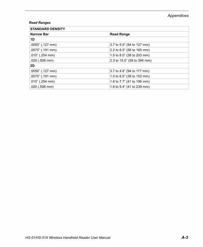
HS-51/HS-51X Wireless Handheld Reader User Manual A-3
Appendices
Read Ranges
STANDARD DENSITY
Narrow Bar Read Range
1D
.0050” (.127 mm) 3.7 to 5.0” (94 to 127 mm)
.0075” (.191 mm) 2.2 to 6.5” (56 to 165 mm)
.010” (.254 mm) 1.5 to 8.0” (38 to 203 mm)
.020 (.508 mm) 2.3 to 15.5” (58 to 394 mm)
2D
.0050” (.127 mm) 3.7 to 4.6” (94 to 117 mm)
.0075” (.191 mm) 1.5 to 6.0” (38 to 152 mm)
.010” (.254 mm) 1.6 to 7.7” (41 to 196 mm)
.020 (.508 mm) 1.6 to 9.4” (41 to 239 mm)

A-4 HS-51/HS-51X Wireless Handheld Reader User Manual
General Specifications
FISes and Accessories
Safety Certifications
FCC, CE, RoHS/WEEE, REACH
©2015 Microscan Systems, Inc.All rights reserved. Specifications subject to change.Product specifications are given for typical performance at 25°C (77°F) using grade A symbols. Performance characteristics may vary at high temperatures or other environmental extremes. Five Year Limited Warranty on parts and labor.
HS-51/HS-51X Wireless Handheld Readers
HS-51 Wireless Handheld 2D Reader FIS-HS51-0001G
HS-51X Wireless Handheld DPM Reader FIS-HS51X-0002G
Charging Station without Embedded Modem, with USB Cable 98-9000007-01
Lithium-Ion Battery 98-9000008-01
Charger, 4 Bay 98-9000009-01
Power Supply, Wall Mount, U.S. 20-000335-02
Power Supply, Wall Mount, EU 20-000336-02
Power Supply, Wall Mount, UK 20-000337-02
Microscan Tools Drive: Software, Documentation, Links to Microscan Website 37-000010-01

HS-51/HS-51X Wireless Handheld Reader User Manual A-5
Appendices
Appendix B — Electrical Specifications
Power RequirementsReader @ 4.2VDC (mA):
Typical and Peak: 362 mA;
Idle: 80 mA;
Sleep: 20 mA
Charging Station with Embedded Modem @ 5VDC (mA):
USB Max Charge Rate: 555 mA;
USB Trickle Charge Rate: 165 mA
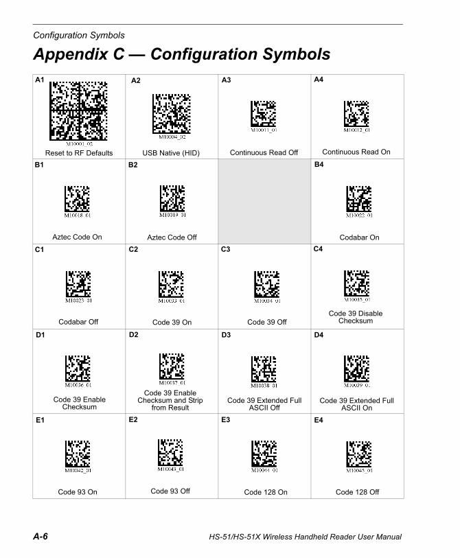
A-6 HS-51/HS-51X Wireless Handheld Reader User Manual
Configuration Symbols
Appendix C — Configuration SymbolsA1
Reset to RF Defaults
A2
USB Native (HID)
A3
Continuous Read Off
A4
Continuous Read On
C1
Codabar Off
C2
Code 39 On
B1
Aztec Code On
B4
Codabar On
C4
Code 39 Disable Checksum
B2
Aztec Code Off
C3
Code 39 Off
D1
Code 39 Enable Checksum
D2
Code 39 Enable Checksum and Strip
from Result
D3
Code 39 Extended Full ASCII Off
D4
Code 39 Extended Full ASCII On
E1
Code 93 On
E2
Code 93 Off
E3
Code 128 On
E4
Code 128 Off
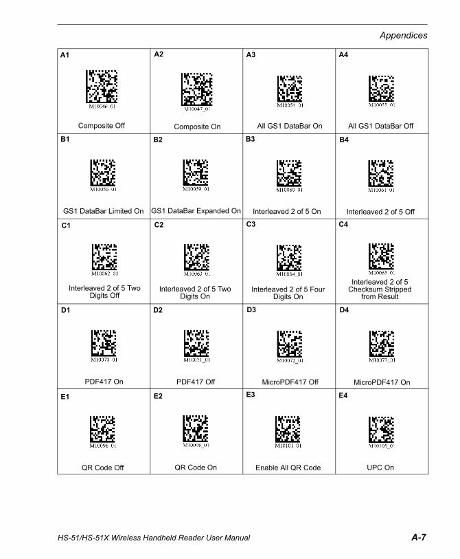
HS-51/HS-51X Wireless Handheld Reader User Manual A-7
Appendices
A1
Composite Off
A2
Composite On
A3
All GS1 DataBar On
A4
All GS1 DataBar Off
B1
GS1 DataBar Limited On
B2
GS1 DataBar Expanded On
B3
Interleaved 2 of 5 On
B4
Interleaved 2 of 5 Off
C1
Interleaved 2 of 5 Two Digits Off
C2
Interleaved 2 of 5 Two Digits On
C3
Interleaved 2 of 5 Four Digits On
C4
Interleaved 2 of 5 Checksum Stripped
from Result
D1
PDF417 On
D2
PDF417 Off
D3
MicroPDF417 Off
D4
MicroPDF417 On
E1
QR Code Off
E2
QR Code On
E3
Enable All QR Code
E4
UPC On

A-8 HS-51/HS-51X Wireless Handheld Reader User Manual
Configuration Symbols
A1
UPC Off
A2
UPC-E as UPC-A Disabled (Default)
A3
UPC-E as UPC-A Enabled
B2
Mirroring Off
B3
Mirroring On
B4
Preamble Erase/None
C1
Preamble Comma
C2
Preamble Space
C3
Preamble Tab
C4
Postamble Erase/None
D1
Postamble Comma
D2
Postamble Space
D3
Postamble Tab
D4
Postamble Enter
E1
Clear Preamble and Postamble
E2
Clear All Stored Data, Images, and JavaScripts
E3
Beep On, Vibrate On
E4
Beep Off, Vibrate On
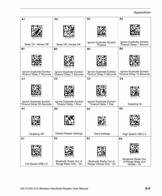
HS-51/HS-51X Wireless Handheld Reader User Manual A-9
Appendices
A1
Beep On, Vibrate Off
A2
Beep Off, Vibrate Off
B1
Ignore Duplicate Symbol Timeout Delay 2 Seconds
B2
Ignore Duplicate Symbol Timeout Delay 3 Seconds
B3
Ignore Duplicate Symbol Timeout Delay 5 Seconds
B4
Ignore Duplicate Symbol Timeout Delay 10 Seconds
C1
Ignore Duplicate Symbol Timeout Delay 30 Seconds
C2
Ignore Duplicate Symbol Timeout Delay 1 Hour
C3
Ignore Duplicate Symbol Timeout Delay 1 Day
C4
Targeting On
D1
Targeting Off
D3
Save Settings
D4
High Speed USB 2.0
E1
Full Speed USB 2.0
E2
Bluetooth Radio Out of Range Beep Only - On
E3
Bluetooth Radio Out of Range Vibrate Only - On
E4
Bluetooth Radio Out of Range Beep and
Vibrate - On
A3 A4
Ignore Duplicate Symbol Timeout
Ignore Duplicate Symbol Timeout Delay 1 Second
D2
Default Reader Settings
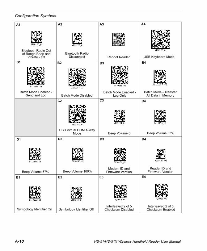
A-10 HS-51/HS-51X Wireless Handheld Reader User Manual
Configuration Symbols
A1
Bluetooth Radio Out of Range Beep and
Vibrate - Off
A2
Bluetooth Radio Disconnect
B1
Batch Mode Enabled - Send and Log
B2
Batch Mode Disabled
B3
Batch Mode Enabled - Log Only
C2
USB Virtual COM 1-Way Mode
C3
Beep Volume 0
D1
Beep Volume 67%
D2
Beep Volume 100%
D3
Modem ID and Firmware Version
E4
Interleaved 2 of 5 Checksum Enabled
C4
Beep Volume 33%
D4
Reader ID and Firmware Version
E1
Symbology Identifier On
E2
Symbology Identifier Off
E3
Interleaved 2 of 5 Checksum Disabled
B4
Batch Mode - Transfer All Data in Memory
A3
Reboot Reader
A4
USB Keyboard Mode
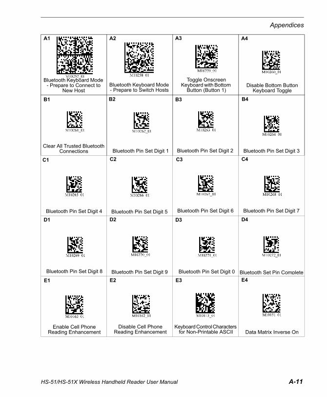
HS-51/HS-51X Wireless Handheld Reader User Manual A-11
Appendices
C2
Bluetooth Pin Set Digit 5
C3
Bluetooth Pin Set Digit 6
C4
Bluetooth Pin Set Digit 7
D1
Bluetooth Pin Set Digit 8
D2
Bluetooth Pin Set Digit 9
A1
Bluetooth Keyboard Mode - Prepare to Connect to
New Host
D3
Bluetooth Pin Set Digit 0
D4
Bluetooth Set Pin Complete
E1
Enable Cell Phone Reading Enhancement
E2
Disable Cell Phone Reading Enhancement
E3
Keyboard Control Characters for Non-Printable ASCII
E4
Data Matrix Inverse On
A3
Toggle Onscreen Keyboard with Bottom
Button (Button 1)
A4
Disable Bottom Button Keyboard Toggle
B1
Clear All Trusted Bluetooth Connections
B2
Bluetooth Pin Set Digit 1
B3
Bluetooth Pin Set Digit 2
B4
Bluetooth Pin Set Digit 3
C1
Bluetooth Pin Set Digit 4
A2
Bluetooth Keyboard Mode - Prepare to Switch Hosts
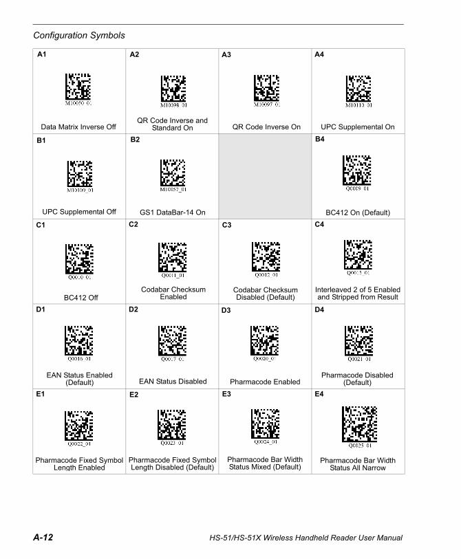
A-12 HS-51/HS-51X Wireless Handheld Reader User Manual
Configuration Symbols
A1
Data Matrix Inverse Off
A2
QR Code Inverse and Standard On
A3
QR Code Inverse On
A4
UPC Supplemental On
B1
UPC Supplemental Off
B2
GS1 DataBar-14 On
B4
BC412 On (Default)
C1
BC412 Off
C2
Codabar Checksum Enabled
C3
Codabar Checksum Disabled (Default)
C4
Interleaved 2 of 5 Enabled and Stripped from Result
D1
EAN Status Enabled (Default)
D2
EAN Status Disabled
D3
Pharmacode Enabled
D4
Pharmacode Disabled (Default)
E4
Pharmacode Bar Width Status All Narrow
E3
Pharmacode Bar Width Status Mixed (Default)
E2
Pharmacode Fixed Symbol Length Disabled (Default)
E1
Pharmacode Fixed Symbol Length Enabled

HS-51/HS-51X Wireless Handheld Reader User Manual A-13
Appendices
A1
Pharmacode Bar Width Status All Wide
A2
Pharmacode Bar Width Status Fixed Threshold
B1
Codabar Checksum Enabled and Stripped
from Result
C1
Data Matrix Disabled
B2
Postal Enabled
A3
Pharmacode Decode Direction Forward (Default)
B3
Postal Disabled (Default)
A4
Pharmacode Decode Direction Reverse
B4
Data Matrix Enabled (Default)
Important: If you disable the Data Matrix symbology, programming symbols will not be decodable by the reader and Data Matrix will need to be re-enabled using ESP.Use the Data Matrix Disabled programming symbol with caution.

A-14 HS-51/HS-51X Wireless Handheld Reader User Manual
Configuration Symbols
Configuration Symbol ReferenceBatch ModeBatch Mode Enabled - Send and Log ........................................................................................... A-10 (B1)Batch Mode Disabled (Default) ..................................................................................................... A-10 (B2)Batch Mode Enabled - Log Only ................................................................................................... A-10 (B3)Batch Mode - Transfer All Data in Memory ................................................................................... A-10 (B4)
BluetoothBluetooth Radio Out of Range Beep Only - On............................................................................... A-9 (E2)Bluetooth Radio Out of Range Vibrate Only - On............................................................................ A-9 (E3)Bluetooth Radio Out of Range Beep and Vibrate - On.................................................................... A-9 (E4)Bluetooth Radio Out of Range Beep and Vibrate - Off (Default) ................................................... A-10 (A1)Bluetooth Radio Disconnect (Reconnect via Quick Connect Code).............................................. A-10 (A2)Bluetooth Keyboard Mode - Prepare to Connect to New Host ...................................................... A-11 (A1)Bluetooth Keyboard Mode - Prepare to Switch Hosts ................................................................... A-11 (A2)Toggle Onscreen Keyboard with Bottom Button (Button 1) ........................................................... A-11 (A3)Disable Bottom Button Keyboard Toggle....................................................................................... A-11 (A4)Clear All Trusted Bluetooth Connections....................................................................................... A-11 (B1)Bluetooth Pin Set Digit 1 ............................................................................................................... A-11 (B2)Bluetooth Pin Set Digit 2 ............................................................................................................... A-11 (B3)Bluetooth Pin Set Digit 3 ............................................................................................................... A-11 (B4)Bluetooth Pin Set Digit 4 ...............................................................................................................A-11 (C1)Bluetooth Pin Set Digit 5 ...............................................................................................................A-11 (C2)Bluetooth Pin Set Digit 6 ...............................................................................................................A-11 (C3)Bluetooth Pin Set Digit 7 ...............................................................................................................A-11 (C4)Bluetooth Pin Set Digit 8 ...............................................................................................................A-11 (D1)Bluetooth Pin Set Digit 9 ...............................................................................................................A-11 (D2)Bluetooth Pin Set Digit 0 ...............................................................................................................A-11 (D3)Bluetooth Set Pin Complete ..........................................................................................................A-11 (D4)
Cell PhoneEnable Cell Phone Reading Enhancement ................................................................................... A-11 (E1)Disable Cell Phone Reading Enhancement .................................................................................. A-11 (E2)
CommunicationsUSB Native (HID) ............................................................................................................................ A-6 (A2)USB Virtual COM 1-Way Mode .....................................................................................................A-10 (C2)USB Keyboard Mode..................................................................................................................... A-10 (A4)High Speed USB 2.0 (Default) ........................................................................................................A-9 (D4)Full Speed USB 2.0......................................................................................................................... A-9 (E1)Keyboard Control Characters for Non-Printable ASCII ................................................................. A-11 (E3)
Continuous ReadContinuous Read On....................................................................................................................... A-6 (A4)Continuous Read Off (Default) ........................................................................................................ A-6 (A3)
FeedbackBeep On Vibrate On (Default) ......................................................................................................... A-8 (E3)Beep Off Vibrate On ........................................................................................................................ A-8 (E4)Beep On Vibrate Off ........................................................................................................................ A-9 (A1)

HS-51/HS-51X Wireless Handheld Reader User Manual A-15
Appendices
Beep Off Vibrate Off.........................................................................................................................A-9 (A2)Beep Volume 0% ...........................................................................................................................A-11 (A1)Beep Volume 33% .........................................................................................................................A-11 (A2)Beep Volume 67% .........................................................................................................................A-11 (A3)Beep Volume 100% (Default) ........................................................................................................A-11 (A4)
ID and Firmware VersionModem ID and Firmware Version ................................................................................................. A-10 (D3)Reader ID and Firmware Version ................................................................................................. A-10 (D4)
Ignore Duplicate Symbol TimeoutIgnore Duplicate Symbol Timeout....................................................................................................A-9 (A3)Ignore Duplicate Symbol Timeout Delay 1 Second .........................................................................A-9 (A4)Ignore Duplicate Symbol Timeout Delay 2 Seconds........................................................................A-9 (B1)Ignore Duplicate Symbol Timeout Delay 3 Seconds........................................................................A-9 (B2)Ignore Duplicate Symbol Timeout Delay 5 Seconds........................................................................A-9 (B3)Ignore Duplicate Symbol Timeout Delay 10 Seconds......................................................................A-9 (B4)Ignore Duplicate Symbol Timeout Delay 30 Seconds..................................................................... A-9 (C1)Ignore Duplicate Symbol Timeout Delay 1 Hour............................................................................. A-9 (C2)Ignore Duplicate Symbol Timeout Delay 1 Day .............................................................................. A-9 (C3)
MirroringMirroring Off (Default) ......................................................................................................................A-8 (B2)Mirroring On .....................................................................................................................................A-8 (B3)
Preamble/PostamblePreamble - Erase/None (Default).....................................................................................................A-8 (B4)Preamble - Comma......................................................................................................................... A-8 (C1)Preamble - Space ........................................................................................................................... A-8 (C2)Preamble - Tab ............................................................................................................................... A-8 (C3)Postamble - Erase/None (Default) .................................................................................................. A-8 (C4)Postamble - Comma ....................................................................................................................... A-8 (D1)Postamble - Space.......................................................................................................................... A-8 (D2)Postamble - Tab.............................................................................................................................. A-8 (D3)Postamble - Enter ........................................................................................................................... A-8 (D4)Clear Preamble and Postamble .......................................................................................................A-8 (E1)
Reset, Reboot, Clear, Default, and SaveReset Reader to RF Factory Defaults..............................................................................................A-6 (A1)Reboot Reader...............................................................................................................................A-10 (A3)Clear All Stored Data, Images, and JavaScripts..............................................................................A-8 (E2)Default Reader Settings.................................................................................................................. A-9 (D2)Save Settings.................................................................................................................................. A-9 (D3)
SymbologiesAztec Code On (Default) ..................................................................................................................A-6 (B1)Aztec Code Off.................................................................................................................................A-6 (B2)BC412 On (Default) .......................................................................................................................A-12 (B4)BC412 Off ..................................................................................................................................... A-12 (C1)Codabar On (Default).......................................................................................................................A-6 (B4)Codabar Off .................................................................................................................................... A-6 (C1)Codabar Checksum Enabled ........................................................................................................ A-12 (C2)
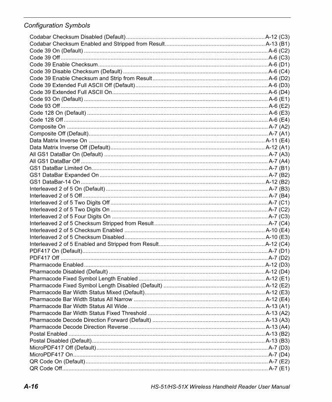
A-16 HS-51/HS-51X Wireless Handheld Reader User Manual
Configuration Symbols
Codabar Checksum Disabled (Default) .........................................................................................A-12 (C3)Codabar Checksum Enabled and Stripped from Result................................................................ A-13 (B1)Code 39 On (Default) ......................................................................................................................A-6 (C2)Code 39 Off .....................................................................................................................................A-6 (C3)Code 39 Enable Checksum.............................................................................................................A-6 (D1)Code 39 Disable Checksum (Default) .............................................................................................A-6 (C4)Code 39 Enable Checksum and Strip from Result ..........................................................................A-6 (D2)Code 39 Extended Full ASCII Off (Default) .....................................................................................A-6 (D3)Code 39 Extended Full ASCII On....................................................................................................A-6 (D4)Code 93 On (Default) ...................................................................................................................... A-6 (E1)Code 93 Off ..................................................................................................................................... A-6 (E2)Code 128 On (Default) .................................................................................................................... A-6 (E3)Code 128 Off ................................................................................................................................... A-6 (E4)Composite On ................................................................................................................................. A-7 (A2)Composite Off (Default)................................................................................................................... A-7 (A1)Data Matrix Inverse On ................................................................................................................. A-11 (E4)Data Matrix Inverse Off (Default)................................................................................................... A-12 (A1)All GS1 DataBar On (Default) ......................................................................................................... A-7 (A3)All GS1 DataBar Off ........................................................................................................................ A-7 (A4)GS1 DataBar Limited On................................................................................................................. A-7 (B1)GS1 DataBar Expanded On ............................................................................................................ A-7 (B2)GS1 DataBar-14 On ...................................................................................................................... A-12 (B2)Interleaved 2 of 5 On (Default) ........................................................................................................ A-7 (B3)Interleaved 2 of 5 Off ....................................................................................................................... A-7 (B4)Interleaved 2 of 5 Two Digits Off .....................................................................................................A-7 (C1)Interleaved 2 of 5 Two Digits On .....................................................................................................A-7 (C2)Interleaved 2 of 5 Four Digits On ....................................................................................................A-7 (C3)Interleaved 2 of 5 Checksum Stripped from Result .........................................................................A-7 (C4)Interleaved 2 of 5 Checksum Enabled .......................................................................................... A-10 (E4)Interleaved 2 of 5 Checksum Disabled.......................................................................................... A-10 (E3)Interleaved 2 of 5 Enabled and Stripped from Result....................................................................A-12 (C4)PDF417 On (Default).......................................................................................................................A-7 (D1)PDF417 Off .....................................................................................................................................A-7 (D2)Pharmacode Enabled....................................................................................................................A-12 (D3)Pharmacode Disabled (Default) ....................................................................................................A-12 (D4)Pharmacode Fixed Symbol Length Enabled ................................................................................. A-12 (E1)Pharmacode Fixed Symbol Length Disabled (Default) ................................................................. A-12 (E2)Pharmacode Bar Width Status Mixed (Default)............................................................................. A-12 (E3)Pharmacode Bar Width Status All Narrow .................................................................................... A-12 (E4)Pharmacode Bar Width Status All Wide........................................................................................ A-13 (A1)Pharmacode Bar Width Status Fixed Threshold ........................................................................... A-13 (A2)Pharmacode Decode Direction Forward (Default) ........................................................................ A-13 (A3)Pharmacode Decode Direction Reverse ....................................................................................... A-13 (A4)Postal Enabled .............................................................................................................................. A-13 (B2)Postal Disabled (Default)............................................................................................................... A-13 (B3)MicroPDF417 Off (Default) ..............................................................................................................A-7 (D3)MicroPDF417 On.............................................................................................................................A-7 (D4)QR Code On (Default) ..................................................................................................................... A-7 (E2)QR Code Off.................................................................................................................................... A-7 (E1)

HS-51/HS-51X Wireless Handheld Reader User Manual A-17
Appendices
Enable All QR Code.........................................................................................................................A-7 (E3)QR Code Inverse and Standard On...............................................................................................A-12 (A2)QR Code Inverse On .....................................................................................................................A-12 (A3)UPC On (Default) .............................................................................................................................A-7 (E4)UPC Off............................................................................................................................................A-8 (A1)UPC-E as UPC-A Enabled...............................................................................................................A-8 (A3)UPC-E as UPC-A Disabled (Default) ...............................................................................................A-8 (A2)UPC Supplemental On...................................................................................................................A-12 (A4)UPC Supplemental Off (Default) ....................................................................................................A-12 (B1)EAN Status Enabled (Default) ...................................................................................................... A-12 (D1)EAN Status Disabled .................................................................................................................... A-12 (D2)Symbology Identifier On.................................................................................................................A-10 (E1)Symbology Identifier Off (Default) ..................................................................................................A-10 (E2)
TargetingTargeting On (Default) .................................................................................................................... A-9 (C4)Targeting Off ................................................................................................................................... A-9 (D1)

A-18 HS-51/HS-51X Wireless Handheld Reader User Manual
Communications Protocol
Appendix D — Communications ProtocolCommunications Protocol Command Table
Protocol Command(Mnemonic displayed on menu)
Control Characters (Entered in menu or serial command)
Hex Value
Effect of Command
RES ^D 04 Reset
REQ ^E 05 Request
EOT ^D 04 Reset
STX ^B 02 Start of Text
ETX ^C 03 End of Text
ACK ^F 06 Acknowledge
NAK ^U 15 Negative Acknowledge
XON ^Q 11 Begin Transmission
XOFF ^S 13 Stop Transmission

HS-51/HS-51X Wireless Handheld Reader User Manual A-19
Appendices
Appendix E — ASCII Table
Dec Hex Mne Ctrl Dec Hex Ch Dec Hex Ch Dec Hex Ch00 00 NUL ^@ 32 20 SP 64 40 @ 96 60 `01 01 SOH ^A 33 21 ! 65 41 A 97 61 a02 02 STX ^B 34 22 “ 66 42 B 98 62 b03 03 ETX ^C 35 23 # 67 43 C 99 63 c04 04 EOT ^D 36 24 $ 68 44 D 100 64 d05 05 ENQ ^E 37 25 % 69 45 E 101 65 e06 06 ACK ^F 38 26 & 70 46 F 102 66 f07 07 BEL ^G 39 27 ' 71 47 G 103 67 g08 08 BS ^H 40 28 ( 72 48 H 104 68 h09 09 HT ^I 41 29 ) 73 49 I 105 69 i10 0A LF ^J 42 2A * 74 4A J 106 6A j11 0B VT ^K 43 2B + 75 4B K 107 6B k12 0C FF ^L 44 2C , 76 4C L 108 6C l13 0D CR ^M 45 2D - 77 4D M 109 6D m14 0E SO ^N 46 2E . 78 4E N 110 6E n15 0F SI ^O 47 2F / 79 4F O 111 6F o16 10 DLE ^P 48 30 0 80 50 P 112 70 p17 11 DC1 ^Q 49 31 1 81 51 Q 113 71 q18 12 DC2 ^R 50 32 2 82 52 R 114 72 r19 13 DC3 ^S 51 33 3 83 53 S 115 73 s20 14 DC4 ^T 52 34 4 84 54 T 116 74 t21 15 NAK ^U 53 35 5 85 55 U 117 75 u22 16 SYN ^V 54 36 6 86 56 V 118 76 v23 17 ETB ^W 55 37 7 87 57 W 119 77 w24 18 CAN ^X 56 38 8 88 58 X 120 78 x25 19 EM ^Y 57 39 9 89 59 Y 121 79 y26 1A SUB ^Z 58 3A : 90 5A Z 122 7A z27 1B ESC ^[ 59 3B ; 91 5B [ 123 7B {28 1C FS ^\ 60 3C < 92 5C \ 124 7C |29 1D GS ^] 61 3D = 93 5D ] 125 7D }30 1E RS ^^ 62 3E > 94 5E ^ 126 7E ~31 1F US ^_ 63 3F ? 95 5F _ 127 7F D

A-20 HS-51/HS-51X Wireless Handheld Reader User Manual
Maintenance
Appendix F — MaintenanceThe HS-51 and HS-51X Wireless Handheld Readers require only a minimum of maintenance to operate.
Cleaning the HS-51 and HS-51X Wireless Handheld ReadersThe following substances are approved for cleaning of the HS-51 and HS-51X.
Product Chemical Content
Alcohol Wipes Isopropyl Alcohol
CaviWipes® Disinfecting Towelettes and CaviCide®
Isopropyl Alcohol, Ethylene Glycol Monobutyl Ether
Clorox® Disinfecting Wipes
Isopropyl Alcohol, n-Alkyl Dimethyl-benzyl Ammonium Chloride, n-Alkyl Dimethyl Ethylbenzyl Ammonium Chloride, Alkyl Polyglucoside, Propylene Glycol Propyl Ether
Clorox® Bleach Solution (10% Clorox bleach, 90% tap water)
Sodium Hypochlorite, Sodium Chloride, Sodium Carbonate, Sodium Hydroxide, Sodium Polyacrylate
Formula 409® Glass and Surface Cleaner
n-Alkyl Dimethyl Benzyl Ammonium Chloride, n-Propoxypropanol
Sani-Cloth® HB, Super Sani-Cloth® Germicidal, Sani-Cloth® Plus Germicidal Disposable Wipes
Quaternary Ammonium Compounds/Chlorides
Virex® II Disinfectant Cleaner n-Alkyl Dimethyl Benzyl Ammonium Chloride, Didecyl Dimethyl Ammonium Chloride
Gentle dish soap and water
HS-51/HS-51X Wireless Handheld Reader User Manual A-21
Appendices
Appendix G — Glossary of TermsAGC — See Automatic Gain Control.
Ambient Light — Light which is present in the environment of the front end of a reader and generated from outside sources. This light, unless used for actual illumination, will be treated as background noise by the reader.
Automatic Gain Control (AGC) — Adjustment to signal strength that seeks to maintain a constant level regardless of the distance between a reader and symbol.
Baud Rate — The number of discrete signal events per second; bits per second.
Check Character — A Modulus 43 or Modulus 10 character that is added to encoded symbol data for additional data integrity.Connector — A plug or socket on a device or cable providing in/out connectivity for various circuits and pins.Decode — A Good Read. The successful interpretation and output of the information encoded in a symbol.Default — Restores ROM or flash settings and initializes serial commands.Delimited — A delimited command or field is bracketed by predefined characters.Decode Rate — The number of good reads per second ahieved by a reader.Depth-of-Field — The in-focus range of a reader. Measured from the distance behind an object to the distance in front of the object with all objects appearing in focus. End of Read Cycle — The time or condition at which the reader stops expecting symbol information to decode.Firmware — Software hard-coded in non-volatile memory (ROM), and closely tied to specific pieces of hardware.Fixed Symbol Length — Increases data integrity by ensuring that only a symbol length will be accepted.Focal Distance — In optics, the distance from the lens to the focal plane.Focal Plane — Usually found at the image sensor, it is a plane perpendicular to the lens axis at the point of focus (–).Focus — Any given point in an image at which light converges; the focal point.Good Read — A decode. The successful scanning and decoding of the information encoded in a bar code symbol.
Host — A computer or other device that is used to execute commands and process data and discrete signals.
Image Sensor — A device that converts a visual image to an electrical signal; a CMOS, for example.
Initialize — Implement serial configuration commands into the reader’s active memory.
Input — A channel or communications line. Decoded data or a discrete signal that is received by a device.
LED (Light-Emitting Diode) — A device that emits light when conducting current.
Lens — A transparent piece of material with curved surfaces which either converge or diverge light rays.
A-22 HS-51/HS-51X Wireless Handheld Reader User Manual
Glossary of Terms
Object Plane — An imaginary plane in the field of view, focused by a reader’s optical system at the corresponding image plane on the sensor.
Output — A channel or communications line. Data or discrete signals that are transmitted or displayed by a device.
Parity — An error detection routine in which one data bit in each character is set to 1 or 0 so that the total number of 1 bits in the data field is even or odd.
Port — Logical circuit for data entry and exit. (One or more ports may be included within a single connector.)
Random Access Memory (RAM) — A data storage system used in computers, composed of integrated circuits that allow access to stored data in any sequence without movement of physical parts.
Read Cycle — A programmed period of time or condition during which a reader will accept symbol input.
Read-Only Memory (ROM) — A data storage medium used in computers and other electronics, primarily used to distribute firmware.
Substrate — The surface upon which a symbol is printed, stamped, or etched.
Symbol Transitions — The transition of bars and spaces on a symbol, used to detect the presence of a symbol on an object.
Symbology — A symbol type, such as Data Matrix or Code 39, with special rules to define the widths and positions of bars and spaces to represent specific numeric or alphanumeric information.