Embed Size (px)
Citation preview
ibm.com/redbooks
HPC Clusters Using InfiniBand on IBM Power Systems Servers
Octavian LascuKerry Bosworth
Hajo KitzhöferJungSu Ko
Nancy MrozGrae Noble
Fernando PizzanoRobert (Bob) Simon
Andrei Vlad
Architecture, terminology, and concepts
Planning and implementation guidance
Useful examples and scenarios
Front cover

HPC Clusters Using InfiniBand on IBM Power Systems Servers
October 2009
International Technical Support Organization
SG24-7767-00

© Copyright International Business Machines Corporation 2009. All rights reserved.Note to U.S. Government Users Restricted Rights -- Use, duplication or disclosure restricted by GSA ADPSchedule Contract with IBM Corp.
First Edition (October 2009)
This edition applies to IBM InfiniBand Offering for Power6-based servers running AIX or Linux and the IBM High Performance Computing (HPC) software stack available at the original date of this publication.
Note: Before using this information and the product it supports, read the information in “Notices” on page xi.
Contents
Notices . . . . . . . . . . . . . . . . . . . . . . . . . . . . . . . . . . . . . . . . . . . . . . . . . . . . . . . xiTrademarks . . . . . . . . . . . . . . . . . . . . . . . . . . . . . . . . . . . . . . . . . . . . . . . . . . . xii
Preface . . . . . . . . . . . . . . . . . . . . . . . . . . . . . . . . . . . . . . . . . . . . . . . . . . . . . . xvThe team that wrote this book . . . . . . . . . . . . . . . . . . . . . . . . . . . . . . . . . . . . . xvBecome a published author . . . . . . . . . . . . . . . . . . . . . . . . . . . . . . . . . . . . . . xviiComments welcome. . . . . . . . . . . . . . . . . . . . . . . . . . . . . . . . . . . . . . . . . . . . xviii
Part 1. Understanding InfiniBand . . . . . . . . . . . . . . . . . . . . . . . . . . . . . . . . . . . . . . . . . . . . . . 1
Chapter 1. InfiniBand architecture. . . . . . . . . . . . . . . . . . . . . . . . . . . . . . . . . 31.1 Introduction to InfiniBand. . . . . . . . . . . . . . . . . . . . . . . . . . . . . . . . . . . . . . . 4
1.1.1 Terminology . . . . . . . . . . . . . . . . . . . . . . . . . . . . . . . . . . . . . . . . . . . . 61.1.2 InfiniBand components . . . . . . . . . . . . . . . . . . . . . . . . . . . . . . . . . . . . 71.1.3 Partitioning . . . . . . . . . . . . . . . . . . . . . . . . . . . . . . . . . . . . . . . . . . . . . 81.1.4 InfiniBand transfer rates and cables . . . . . . . . . . . . . . . . . . . . . . . . . 10
1.2 I/O architecture: bus versus fabric. . . . . . . . . . . . . . . . . . . . . . . . . . . . . . . 121.2.1 Shared bus architecture . . . . . . . . . . . . . . . . . . . . . . . . . . . . . . . . . . 131.2.2 Fabric architecture . . . . . . . . . . . . . . . . . . . . . . . . . . . . . . . . . . . . . . 131.2.3 Example: SCSI bus versus SAN fabric . . . . . . . . . . . . . . . . . . . . . . . 131.2.4 Fabric versus bus architecture comparison . . . . . . . . . . . . . . . . . . . 141.2.5 InfiniBand enablers . . . . . . . . . . . . . . . . . . . . . . . . . . . . . . . . . . . . . . 151.2.6 InfiniBand: bandwidth out of the box . . . . . . . . . . . . . . . . . . . . . . . . . 16
1.3 Application clustering . . . . . . . . . . . . . . . . . . . . . . . . . . . . . . . . . . . . . . . . 161.4 Clustering with InfiniBand . . . . . . . . . . . . . . . . . . . . . . . . . . . . . . . . . . . . . 17
1.4.1 The interconnect . . . . . . . . . . . . . . . . . . . . . . . . . . . . . . . . . . . . . . . . 171.4.2 Bandwidth versus latency . . . . . . . . . . . . . . . . . . . . . . . . . . . . . . . . . 181.4.3 Why clusters exploit InfiniBand . . . . . . . . . . . . . . . . . . . . . . . . . . . . . 19
1.5 InfiniBand communication and management architecture overview . . . . . 201.5.1 Communication . . . . . . . . . . . . . . . . . . . . . . . . . . . . . . . . . . . . . . . . . 211.5.2 Fabric management . . . . . . . . . . . . . . . . . . . . . . . . . . . . . . . . . . . . . 281.5.3 Overview of IB protocols . . . . . . . . . . . . . . . . . . . . . . . . . . . . . . . . . . 33
1.6 IBM InfiniBand implementation . . . . . . . . . . . . . . . . . . . . . . . . . . . . . . . . . 391.7 Summary . . . . . . . . . . . . . . . . . . . . . . . . . . . . . . . . . . . . . . . . . . . . . . . . . . 40
Chapter 2. High performance computing hardware components using InfiniBand . . . . . . . . . . . . . . . . . . . . . . . . . . . . . . . . . . . . . . . . . . 41
2.1 HPC environment overview. . . . . . . . . . . . . . . . . . . . . . . . . . . . . . . . . . . . 422.2 POWER6 Systems . . . . . . . . . . . . . . . . . . . . . . . . . . . . . . . . . . . . . . . . . . 44
© Copyright IBM Corp. 2009. All rights reserved. iii
2.2.1 Supported POWER6 Systems for HPC with IB. . . . . . . . . . . . . . . . . 452.2.2 Hardware Management Console (HMC). . . . . . . . . . . . . . . . . . . . . . 602.2.3 POWER Systems firmware . . . . . . . . . . . . . . . . . . . . . . . . . . . . . . . . 612.2.4 Power Hypervisor . . . . . . . . . . . . . . . . . . . . . . . . . . . . . . . . . . . . . . . 65
2.3 Host channel adapter . . . . . . . . . . . . . . . . . . . . . . . . . . . . . . . . . . . . . . . . 672.3.1 Sharing the HCA . . . . . . . . . . . . . . . . . . . . . . . . . . . . . . . . . . . . . . . . 692.3.2 Supported host channel adapters in an HPC environment . . . . . . . . 71
2.4 HCA and LPARs . . . . . . . . . . . . . . . . . . . . . . . . . . . . . . . . . . . . . . . . . . . . 732.4.1 Recommendation for GUID in LPARs. . . . . . . . . . . . . . . . . . . . . . . . 742.4.2 Considerations for micro-partitioning . . . . . . . . . . . . . . . . . . . . . . . . 74
2.5 InfiniBand cables . . . . . . . . . . . . . . . . . . . . . . . . . . . . . . . . . . . . . . . . . . . . 742.6 InfiniBand switches . . . . . . . . . . . . . . . . . . . . . . . . . . . . . . . . . . . . . . . . . . 77
2.6.1 IBM Power 7874 InfiniBand switches . . . . . . . . . . . . . . . . . . . . . . . . 772.6.2 Host subnet manager . . . . . . . . . . . . . . . . . . . . . . . . . . . . . . . . . . . . 84
2.7 Cluster management server . . . . . . . . . . . . . . . . . . . . . . . . . . . . . . . . . . . 86
Chapter 3. Technical description of software components. . . . . . . . . . . . 873.1 AIX and Linux on POWER using InfiniBand . . . . . . . . . . . . . . . . . . . . . . . 88
3.1.1 Solution components. . . . . . . . . . . . . . . . . . . . . . . . . . . . . . . . . . . . . 883.1.2 HPC stack overview . . . . . . . . . . . . . . . . . . . . . . . . . . . . . . . . . . . . . 893.1.3 AIX IB software architecture . . . . . . . . . . . . . . . . . . . . . . . . . . . . . . . 903.1.4 InfiniBand software implementation on Linux . . . . . . . . . . . . . . . . . . 96
3.2 Management subsystem overview . . . . . . . . . . . . . . . . . . . . . . . . . . . . . 1003.2.1 Network definitions . . . . . . . . . . . . . . . . . . . . . . . . . . . . . . . . . . . . . 1013.2.2 Fabric Management Server. . . . . . . . . . . . . . . . . . . . . . . . . . . . . . . 1033.2.3 IBM InfiniBand 7874 switch series . . . . . . . . . . . . . . . . . . . . . . . . . 1063.2.4 Nodes (compute, I/O) . . . . . . . . . . . . . . . . . . . . . . . . . . . . . . . . . . . 1083.2.5 Cluster management node (server) . . . . . . . . . . . . . . . . . . . . . . . . 1093.2.6 Hardware Management Console . . . . . . . . . . . . . . . . . . . . . . . . . . 110
3.3 HPC IB stack overview . . . . . . . . . . . . . . . . . . . . . . . . . . . . . . . . . . . . . . 1103.3.1 HPC infrastructure management software . . . . . . . . . . . . . . . . . . . 1113.3.2 HPC application software . . . . . . . . . . . . . . . . . . . . . . . . . . . . . . . . 1143.3.3 How HPC SW components work together . . . . . . . . . . . . . . . . . . . 117
Part 2. Planning for InfiniBand. . . . . . . . . . . . . . . . . . . . . . . . . . . . . . . . . . . . . . . . . . . . . . . 121
Chapter 4. Planning for an HPC cluster . . . . . . . . . . . . . . . . . . . . . . . . . . 1234.1 Planning cycle . . . . . . . . . . . . . . . . . . . . . . . . . . . . . . . . . . . . . . . . . . . . . 1244.2 Understanding the requirements . . . . . . . . . . . . . . . . . . . . . . . . . . . . . . . 1244.3 Design criteria for an HPC system . . . . . . . . . . . . . . . . . . . . . . . . . . . . . 125
4.3.1 What FLOPS means . . . . . . . . . . . . . . . . . . . . . . . . . . . . . . . . . . . . 1264.3.2 Preliminary cluster sizing . . . . . . . . . . . . . . . . . . . . . . . . . . . . . . . . 1274.3.3 The role of benchmarks . . . . . . . . . . . . . . . . . . . . . . . . . . . . . . . . . 128
4.4 Selection options for an HPC system . . . . . . . . . . . . . . . . . . . . . . . . . . . 130
iv HPC Clusters Using InfiniBand on IBM Power Systems Servers

4.4.1 How a typical HPC system looks . . . . . . . . . . . . . . . . . . . . . . . . . . 1314.4.2 Focus areas . . . . . . . . . . . . . . . . . . . . . . . . . . . . . . . . . . . . . . . . . . 1324.4.3 Compute node criteria. . . . . . . . . . . . . . . . . . . . . . . . . . . . . . . . . . . 1334.4.4 Special purpose nodes . . . . . . . . . . . . . . . . . . . . . . . . . . . . . . . . . . 1344.4.5 Type of interconnect . . . . . . . . . . . . . . . . . . . . . . . . . . . . . . . . . . . . 1354.4.6 Additional networks . . . . . . . . . . . . . . . . . . . . . . . . . . . . . . . . . . . . . 1394.4.7 Public IP addresses: IP address ranges . . . . . . . . . . . . . . . . . . . . . 1394.4.8 Operating system selection. . . . . . . . . . . . . . . . . . . . . . . . . . . . . . . 1394.4.9 Storage options . . . . . . . . . . . . . . . . . . . . . . . . . . . . . . . . . . . . . . . . 1394.4.10 Parallel file systems . . . . . . . . . . . . . . . . . . . . . . . . . . . . . . . . . . . 1404.4.11 Backup/archive considerations . . . . . . . . . . . . . . . . . . . . . . . . . . . 1464.4.12 Job scheduler . . . . . . . . . . . . . . . . . . . . . . . . . . . . . . . . . . . . . . . . 1474.4.13 Cluster management software . . . . . . . . . . . . . . . . . . . . . . . . . . . 1494.4.14 Application development . . . . . . . . . . . . . . . . . . . . . . . . . . . . . . . . 1494.4.15 Facility considerations. . . . . . . . . . . . . . . . . . . . . . . . . . . . . . . . . . 1504.4.16 Maintaining an HPC cluster. . . . . . . . . . . . . . . . . . . . . . . . . . . . . . 1514.4.17 Availability considerations . . . . . . . . . . . . . . . . . . . . . . . . . . . . . . . 152
4.5 Decision criteria. . . . . . . . . . . . . . . . . . . . . . . . . . . . . . . . . . . . . . . . . . . . 1524.6 Sample HPC cluster configurations. . . . . . . . . . . . . . . . . . . . . . . . . . . . . 153
4.6.1 HPC cluster with shared disk storage subsystems . . . . . . . . . . . . . 1544.6.2 HPC cluster with dedicated I/O servers . . . . . . . . . . . . . . . . . . . . . 1544.6.3 HPC cluster with dedicated I/O servers and archive subsystem. . . 1564.6.4 Complex cluster configuration. . . . . . . . . . . . . . . . . . . . . . . . . . . . . 156
Part 3. Implementing InfiniBand . . . . . . . . . . . . . . . . . . . . . . . . . . . . . . . . . . . . . . . . . . . . . 159
Chapter 5. Implementation overview . . . . . . . . . . . . . . . . . . . . . . . . . . . . . 1615.1 Environment description . . . . . . . . . . . . . . . . . . . . . . . . . . . . . . . . . . . . . 162
5.1.1 Network topology . . . . . . . . . . . . . . . . . . . . . . . . . . . . . . . . . . . . . . 1635.1.2 InfiniBand topology . . . . . . . . . . . . . . . . . . . . . . . . . . . . . . . . . . . . . 170
5.2 Test applications overview . . . . . . . . . . . . . . . . . . . . . . . . . . . . . . . . . . . 1715.2.1 Message passing interface (MPI) threads sample application . . . . 1715.2.2 Bandwidth (BW) sample application . . . . . . . . . . . . . . . . . . . . . . . . 1725.2.3 CAST sample application . . . . . . . . . . . . . . . . . . . . . . . . . . . . . . . . 172
5.3 Implementation summary . . . . . . . . . . . . . . . . . . . . . . . . . . . . . . . . . . . . 1725.3.1 Prepare hardware . . . . . . . . . . . . . . . . . . . . . . . . . . . . . . . . . . . . . . 1735.3.2 Configure environment . . . . . . . . . . . . . . . . . . . . . . . . . . . . . . . . . . 1735.3.3 Deployment of the HPC stack . . . . . . . . . . . . . . . . . . . . . . . . . . . . . 1755.3.4 Cluster application that exploit InfiniBand . . . . . . . . . . . . . . . . . . . . 176
Chapter 6. Configuring the InfiniBand fabric . . . . . . . . . . . . . . . . . . . . . . 1776.1 InfiniBand fabric setup description . . . . . . . . . . . . . . . . . . . . . . . . . . . . . 1786.2 Preparing the InfiniBand switch. . . . . . . . . . . . . . . . . . . . . . . . . . . . . . . . 179
6.2.1 IP configuration . . . . . . . . . . . . . . . . . . . . . . . . . . . . . . . . . . . . . . . . 182
Contents v
6.2.2 Time synchronization . . . . . . . . . . . . . . . . . . . . . . . . . . . . . . . . . . . 1866.2.3 InfiniBand operational log (syslog) configuration . . . . . . . . . . . . . . 1866.2.4 Updating the firmware . . . . . . . . . . . . . . . . . . . . . . . . . . . . . . . . . . . 1876.2.5 Configuring SNMP . . . . . . . . . . . . . . . . . . . . . . . . . . . . . . . . . . . . . 1886.2.6 Configuring SSH . . . . . . . . . . . . . . . . . . . . . . . . . . . . . . . . . . . . . . . 189
6.3 Preparing the Fabric Manager servers . . . . . . . . . . . . . . . . . . . . . . . . . . 1906.3.1 Installing the operating system . . . . . . . . . . . . . . . . . . . . . . . . . . . . 1916.3.2 Install the QLogic InfiniBand Fabric Suite FastFabric Toolset . . . . 1936.3.3 Fast fabric configuration . . . . . . . . . . . . . . . . . . . . . . . . . . . . . . . . . 195
6.4 Verifying the Fabric Manager configuration. . . . . . . . . . . . . . . . . . . . . . . 200
Chapter 7. Configuring InfiniBand on AIX . . . . . . . . . . . . . . . . . . . . . . . . 2057.1 Software environment . . . . . . . . . . . . . . . . . . . . . . . . . . . . . . . . . . . . . . . 2067.2 Configuring the xCAT2 management node . . . . . . . . . . . . . . . . . . . . . . . 207
7.2.1 Configuring the OS for the xCAT management node . . . . . . . . . . . 2087.2.2 Downloading and installing prerequisite open source software . . . 2107.2.3 Downloading and installing the xCAT software. . . . . . . . . . . . . . . . 2117.2.4 Configuring the xCAT management node. . . . . . . . . . . . . . . . . . . . 2127.2.5 Installing compute nodes . . . . . . . . . . . . . . . . . . . . . . . . . . . . . . . . 216
7.3 Installing the HPC stack . . . . . . . . . . . . . . . . . . . . . . . . . . . . . . . . . . . . . 2177.3.1 GPFS installation and configuration . . . . . . . . . . . . . . . . . . . . . . . . 2197.3.2 Installing compliers . . . . . . . . . . . . . . . . . . . . . . . . . . . . . . . . . . . . . 2257.3.3 PE installation and testing. . . . . . . . . . . . . . . . . . . . . . . . . . . . . . . . 2277.3.4 Creating an RSCT Peer Domain (RPD) for compute nodes . . . . . . 2307.3.5 LoadLeveler installation and configuration . . . . . . . . . . . . . . . . . . . 231
7.4 Start the application. . . . . . . . . . . . . . . . . . . . . . . . . . . . . . . . . . . . . . . . . 2327.4.1 MPI thread sample application . . . . . . . . . . . . . . . . . . . . . . . . . . . . 2327.4.2 Bandwidth sample application. . . . . . . . . . . . . . . . . . . . . . . . . . . . . 2337.4.3 Broadcast sample application . . . . . . . . . . . . . . . . . . . . . . . . . . . . . 233
Chapter 8. Configuring InfiniBand on Linux on Power . . . . . . . . . . . . . . 2358.1 Software environment . . . . . . . . . . . . . . . . . . . . . . . . . . . . . . . . . . . . . . . 2368.2 Configuring the xCAT management node . . . . . . . . . . . . . . . . . . . . . . . . 237
8.2.1 Configuring the OS for the xCAT management node . . . . . . . . . . . 2388.2.2 Installing prerequisite Open Source Software and xCAT code . . . . 2398.2.3 Configuring the xCAT environment . . . . . . . . . . . . . . . . . . . . . . . . . 2418.2.4 Installing compute nodes . . . . . . . . . . . . . . . . . . . . . . . . . . . . . . . . 2478.2.5 Configuring the InfiniBand drivers . . . . . . . . . . . . . . . . . . . . . . . . . . 2508.2.6 Setting up logging in xCAT using syslog-ng . . . . . . . . . . . . . . . . . . 252
8.3 Installing the HPC stack . . . . . . . . . . . . . . . . . . . . . . . . . . . . . . . . . . . . . 2578.3.1 Installing the HPC software using xCAT . . . . . . . . . . . . . . . . . . . . . 2588.3.2 Configuring the HPC software. . . . . . . . . . . . . . . . . . . . . . . . . . . . . 266
8.4 Starting the application . . . . . . . . . . . . . . . . . . . . . . . . . . . . . . . . . . . . . . 277
vi HPC Clusters Using InfiniBand on IBM Power Systems Servers
8.4.1 MPI threads sample application . . . . . . . . . . . . . . . . . . . . . . . . . . . 2778.4.2 Bandwidth sample application. . . . . . . . . . . . . . . . . . . . . . . . . . . . . 2788.4.3 Broadcast sample application . . . . . . . . . . . . . . . . . . . . . . . . . . . . . 279
8.5 References . . . . . . . . . . . . . . . . . . . . . . . . . . . . . . . . . . . . . . . . . . . . . . . 280
Part 4. Managing the InfiniBand environment . . . . . . . . . . . . . . . . . . . . . . . . . . . . . . . . . . 281
Chapter 9. Fabric management and monitoring. . . . . . . . . . . . . . . . . . . . 2839.1 Introduction to the FastFabric Toolset. . . . . . . . . . . . . . . . . . . . . . . . . . . 2849.2 Switch CLI . . . . . . . . . . . . . . . . . . . . . . . . . . . . . . . . . . . . . . . . . . . . . . . . 2889.3 Fast Fabric analysis example . . . . . . . . . . . . . . . . . . . . . . . . . . . . . . . . . 290
9.3.1 Mapping devices . . . . . . . . . . . . . . . . . . . . . . . . . . . . . . . . . . . . . . . 2909.3.2 Link port counters . . . . . . . . . . . . . . . . . . . . . . . . . . . . . . . . . . . . . . 2979.3.3 Link integrity . . . . . . . . . . . . . . . . . . . . . . . . . . . . . . . . . . . . . . . . . . 2989.3.4 Recognizing congestion . . . . . . . . . . . . . . . . . . . . . . . . . . . . . . . . . 3029.3.5 Identifying sources of congestion . . . . . . . . . . . . . . . . . . . . . . . . . . 3059.3.6 Tracing a route . . . . . . . . . . . . . . . . . . . . . . . . . . . . . . . . . . . . . . . . 3089.3.7 Link counter summary. . . . . . . . . . . . . . . . . . . . . . . . . . . . . . . . . . . 3149.3.8 Baseline and health checks . . . . . . . . . . . . . . . . . . . . . . . . . . . . . . 3149.3.9 Link problem determination. . . . . . . . . . . . . . . . . . . . . . . . . . . . . . . 3169.3.10 Interpreting QLogic Fabric Manager logs . . . . . . . . . . . . . . . . . . . 3229.3.11 Fabric software and hardware maintenance and support . . . . . . . 3279.3.12 Failover and recovery scenarios . . . . . . . . . . . . . . . . . . . . . . . . . . 334
9.4 QLogic knowledge base . . . . . . . . . . . . . . . . . . . . . . . . . . . . . . . . . . . . . 337
Chapter 10. Node management and monitoring . . . . . . . . . . . . . . . . . . . 33910.1 Managing compute nodes . . . . . . . . . . . . . . . . . . . . . . . . . . . . . . . . . . . 340
10.1.1 xCAT2 InfiniBand management on AIX and Linux . . . . . . . . . . . . 34010.1.2 Operational log management . . . . . . . . . . . . . . . . . . . . . . . . . . . . 34510.1.3 HPC software stack management. . . . . . . . . . . . . . . . . . . . . . . . . 347
10.2 Monitoring nodes. . . . . . . . . . . . . . . . . . . . . . . . . . . . . . . . . . . . . . . . . . 34810.2.1 Monitoring and troubleshooting on AIX . . . . . . . . . . . . . . . . . . . . . 34810.2.2 Monitoring and troubleshooting on Linux . . . . . . . . . . . . . . . . . . . 35710.2.3 Another monitoring tool: Ganglia. . . . . . . . . . . . . . . . . . . . . . . . . . 36410.2.4 Troubleshooting tools from HPC stack . . . . . . . . . . . . . . . . . . . . . 36410.2.5 Congestion in an InfiniBand Fabric . . . . . . . . . . . . . . . . . . . . . . . . 365
10.3 End-to-end startup/shutdown procedures . . . . . . . . . . . . . . . . . . . . . . . 36510.3.1 End-to-end shutdown procedure. . . . . . . . . . . . . . . . . . . . . . . . . . 36510.3.2 End-to-end startup procedure . . . . . . . . . . . . . . . . . . . . . . . . . . . . 366
Part 5. Appendixes . . . . . . . . . . . . . . . . . . . . . . . . . . . . . . . . . . . . . . . . . . . . . . . . . . . . . . . . 367
Appendix A. Advanced syslog-ng configuration . . . . . . . . . . . . . . . . . . . 369
Contents vii
Appendix B. Fabric port counters . . . . . . . . . . . . . . . . . . . . . . . . . . . . . . . 381Port counter errors . . . . . . . . . . . . . . . . . . . . . . . . . . . . . . . . . . . . . . . . . . . . . 382Link integrity errors. . . . . . . . . . . . . . . . . . . . . . . . . . . . . . . . . . . . . . . . . . . . . 382Remote link integrity errors . . . . . . . . . . . . . . . . . . . . . . . . . . . . . . . . . . . . . . 384Security errors . . . . . . . . . . . . . . . . . . . . . . . . . . . . . . . . . . . . . . . . . . . . . . . . 385Other errors . . . . . . . . . . . . . . . . . . . . . . . . . . . . . . . . . . . . . . . . . . . . . . . . . . 385
Appendix C. Fabric Management scripts . . . . . . . . . . . . . . . . . . . . . . . . . 387Introduction. . . . . . . . . . . . . . . . . . . . . . . . . . . . . . . . . . . . . . . . . . . . . . . . . . . 388
Appendix D. AIX ibstat -s output description . . . . . . . . . . . . . . . . . . . . . . 401Transmit counters. . . . . . . . . . . . . . . . . . . . . . . . . . . . . . . . . . . . . . . . . . . . . . 402Receive counters . . . . . . . . . . . . . . . . . . . . . . . . . . . . . . . . . . . . . . . . . . . . . . 404Connection manager counters . . . . . . . . . . . . . . . . . . . . . . . . . . . . . . . . . . . . 407
Appendix E. Recommended MPI environment settings . . . . . . . . . . . . . 409LAPI_DEBUG_ENABLE_AFFINITY=YES . . . . . . . . . . . . . . . . . . . . . . . . . . . 410LAPI_DEBUG_BINDPROC_AFFINITY=YES. . . . . . . . . . . . . . . . . . . . . . . . . 410LAPI_DEBUG_MTU_4K=yes . . . . . . . . . . . . . . . . . . . . . . . . . . . . . . . . . . . . . 410MP_FIFO_MTU=4K . . . . . . . . . . . . . . . . . . . . . . . . . . . . . . . . . . . . . . . . . . . . 411MP_SYNC_QP=YES . . . . . . . . . . . . . . . . . . . . . . . . . . . . . . . . . . . . . . . . . . . 411MP_RFIFO_SIZE=16777216 . . . . . . . . . . . . . . . . . . . . . . . . . . . . . . . . . . . . . 411MP_SHM_ATTACH_THRESH=500000. . . . . . . . . . . . . . . . . . . . . . . . . . . . . 411MP_EUIDEVELOP=min . . . . . . . . . . . . . . . . . . . . . . . . . . . . . . . . . . . . . . . . . 412MP_SINGLE_THREAD=yes . . . . . . . . . . . . . . . . . . . . . . . . . . . . . . . . . . . . . 412MP_USE_BULK_XFER=yes . . . . . . . . . . . . . . . . . . . . . . . . . . . . . . . . . . . . . 412MP_RDMA_MTU=4K . . . . . . . . . . . . . . . . . . . . . . . . . . . . . . . . . . . . . . . . . . . 413MP_BULK_MIN_MSG_SIZE=64k . . . . . . . . . . . . . . . . . . . . . . . . . . . . . . . . . 413MP_RC_MAX_QP=8192 . . . . . . . . . . . . . . . . . . . . . . . . . . . . . . . . . . . . . . . . 413LAPI_DEBUG_RC_DREG_THRESHOLD= 1000000 . . . . . . . . . . . . . . . . . . 413LAPI_DEBUG_QP_NOTIFICATION=no . . . . . . . . . . . . . . . . . . . . . . . . . . . . 414LAPI_DEBUG_RC_INIT_SETUP=yes . . . . . . . . . . . . . . . . . . . . . . . . . . . . . . 414LAPI_DEBUG_RDMA_AFFINITY=YES. . . . . . . . . . . . . . . . . . . . . . . . . . . . . 414MP_POLLING_INTERVAL=800000. . . . . . . . . . . . . . . . . . . . . . . . . . . . . . . . 414MP_RETRANSMIT_INTERVAL=8000000 . . . . . . . . . . . . . . . . . . . . . . . . . . . 415LAPI_DEBUG_SEND_FLIP=8 . . . . . . . . . . . . . . . . . . . . . . . . . . . . . . . . . . . . 415LAPI_DEBUG_ACK_THRESH=16. . . . . . . . . . . . . . . . . . . . . . . . . . . . . . . . . 415MP_BULK_XFER_CHUNK_SIZE=1024k . . . . . . . . . . . . . . . . . . . . . . . . . . . 415
Related publications . . . . . . . . . . . . . . . . . . . . . . . . . . . . . . . . . . . . . . . . . . 417IBM Redbooks publications . . . . . . . . . . . . . . . . . . . . . . . . . . . . . . . . . . . . . . 417Other publications . . . . . . . . . . . . . . . . . . . . . . . . . . . . . . . . . . . . . . . . . . . . . 417Online resources . . . . . . . . . . . . . . . . . . . . . . . . . . . . . . . . . . . . . . . . . . . . . . 417How to get Redbooks publications . . . . . . . . . . . . . . . . . . . . . . . . . . . . . . . . . 418
viii HPC Clusters Using InfiniBand on IBM Power Systems Servers

Help from IBM . . . . . . . . . . . . . . . . . . . . . . . . . . . . . . . . . . . . . . . . . . . . . . . . 418
Index . . . . . . . . . . . . . . . . . . . . . . . . . . . . . . . . . . . . . . . . . . . . . . . . . . . . . . . 419
Contents ix

x HPC Clusters Using InfiniBand on IBM Power Systems Servers

Notices
This information was developed for products and services offered in the U.S.A.
IBM may not offer the products, services, or features discussed in this document in other countries. Consult your local IBM representative for information on the products and services currently available in your area. Any reference to an IBM product, program, or service is not intended to state or imply that only that IBM product, program, or service may be used. Any functionally equivalent product, program, or service that does not infringe any IBM intellectual property right may be used instead. However, it is the user's responsibility to evaluate and verify the operation of any non-IBM product, program, or service.
IBM may have patents or pending patent applications covering subject matter described in this document. The furnishing of this document does not give you any license to these patents. You can send license inquiries, in writing, to: IBM Director of Licensing, IBM Corporation, North Castle Drive, Armonk, NY 10504-1785 U.S.A.
The following paragraph does not apply to the United Kingdom or any other country where such provisions are inconsistent with local law: INTERNATIONAL BUSINESS MACHINES CORPORATION PROVIDES THIS PUBLICATION "AS IS" WITHOUT WARRANTY OF ANY KIND, EITHER EXPRESS OR IMPLIED, INCLUDING, BUT NOT LIMITED TO, THE IMPLIED WARRANTIES OF NON-INFRINGEMENT, MERCHANTABILITY OR FITNESS FOR A PARTICULAR PURPOSE. Some states do not allow disclaimer of express or implied warranties in certain transactions, therefore, this statement may not apply to you.
This information could include technical inaccuracies or typographical errors. Changes are periodically made to the information herein; these changes will be incorporated in new editions of the publication. IBM may make improvements and/or changes in the product(s) and/or the program(s) described in this publication at any time without notice.
Any references in this information to non-IBM Web sites are provided for convenience only and do not in any manner serve as an endorsement of those Web sites. The materials at those Web sites are not part of the materials for this IBM product and use of those Web sites is at your own risk.
IBM may use or distribute any of the information you supply in any way it believes appropriate without incurring any obligation to you.
Information concerning non-IBM products was obtained from the suppliers of those products, their published announcements or other publicly available sources. IBM has not tested those products and cannot confirm the accuracy of performance, compatibility or any other claims related to non-IBM products. Questions on the capabilities of non-IBM products should be addressed to the suppliers of those products.
This information contains examples of data and reports used in daily business operations. To illustrate them as completely as possible, the examples include the names of individuals, companies, brands, and products. All of these names are fictitious and any similarity to the names and addresses used by an actual business enterprise is entirely coincidental.
COPYRIGHT LICENSE:
This information contains sample application programs in source language, which illustrate programming techniques on various operating platforms. You may copy, modify, and distribute these sample programs in any form without payment to IBM, for the purposes of developing, using, marketing or distributing application programs conforming to the application programming interface for the operating platform for which the sample programs are written. These examples have not been thoroughly tested under all conditions. IBM, therefore, cannot guarantee or imply reliability, serviceability, or function of these programs.
© Copyright IBM Corp. 2009. All rights reserved. xi

Trademarks
IBM, the IBM logo, and ibm.com are trademarks or registered trademarks of International Business Machines Corporation in the United States, other countries, or both. These and other IBM trademarked terms are marked on their first occurrence in this information with the appropriate symbol (® or ™), indicating US registered or common law trademarks owned by IBM at the time this information was published. Such trademarks may also be registered or common law trademarks in other countries. A current list of IBM trademarks is available on the Web at http://www.ibm.com/legal/copytrade.shtml
The following terms are trademarks of the International Business Machines Corporation in the United States, other countries, or both:
AIX 5L™AIX®BladeCenter®Blue Gene®DB2®EnergyScale™FlashCopy®Focal Point™GPFS™HACMP™i5/OS®
IBM®LoadLeveler®Micro-Partitioning™Power Architecture®POWER Hypervisor™Power Systems™POWER4™POWER5™POWER6®PowerPC®PowerVM™
POWER®pSeries®Redbooks®Redbooks (logo) ®RS/6000®Solid®System p®System x®System z®Tivoli®
The following terms are trademarks of other companies:
Cell Broadband Engine and Cell/B.E. are trademarks of Sony Computer Entertainment, Inc., in the United States, other countries, or both and is used under license therefrom.
InfiniBand Trade Association, InfiniBand, and the InfiniBand design marks are trademarks and/or service marks of the InfiniBand Trade Association.
SUSE, the Novell logo, and the N logo are registered trademarks of Novell, Inc. in the United States and other countries.
Oracle, JD Edwards, PeopleSoft, Siebel, and TopLink are registered trademarks of Oracle Corporation and/or its affiliates.
QLogic, SilverStorm, InfiniBand Fabric Suite, Fabric Manager, Fabric Executive, and the QLogic logo are registered trademarks of QLogic Corporation. SANblade is a registered trademark in the United States.
MySQL, Solaris, Ultra, and all Java-based trademarks are trademarks of Sun Microsystems, Inc. in the United States, other countries, or both.
Microsoft, Windows, and the Windows logo are trademarks of Microsoft Corporation in the United States, other countries, or both.
Itanium, Pentium, Intel logo, Intel Inside logo, and Intel Centrino logo are trademarks or registered trademarks of Intel Corporation or its subsidiaries in the United States and other countries.
UNIX is a registered trademark of The Open Group in the United States and other countries.
Linux is a trademark of Linus Torvalds in the United States, other countries, or both.
Other company, product, or service names may be trademarks or service marks of others.
xii HPC Clusters Using InfiniBand on IBM Power Systems Servers

Preface
This IBM® Redbooks® publication provides information about the InfiniBand standard and how the standard has been implemented to support IBM High Performance Computing (HPC) clusters running on IBM Power 6 servers.
This book will help you understand, plan, implement, and manage InfiniBand using IBM servers and switches to form a high-bandwidth, low-latency communication network for applications.
This book presents the software and hardware components that together form the management and application foundation. We cover cluster management, node installation, monitoring, and application support for IBM TWS LoadLeveler®, Parallel Environment, and various other AIX® and SUSE SLES tools.
This book is intended for IT architects, system designers, data center planners, and system administrators who must design, configure, and manage an InfiniBand infrastructure in an HPC cluster.
The team who wrote this book
This book was produced by a team of specialists from around the world working at the International Technical Support Organization, Poughkeepsie Center.
Octavian Lascu is a Project Leader associated with the ITSO, Poughkeepsie Center. He writes extensively and teaches IBM classes worldwide on all areas of IBM System p® and Linux® clusters. His areas of expertise include high performance computing, Blue Gene®, and clusters. Before joining ITSO, Octavian worked in IBM Global Services Romania as a server and storage Services Manager. He holds a master’s degree in Electronic Engineering from the Polytechnical Institute in Bucharest and is also an IBM Certified Advanced Technical Expert in AIX/PSSP/HACMP™. He has worked for IBM since 1992.
Kerry Bosworth is a Software Engineer in pSeries® Cluster System Test for high performance computing in Poughkeepsie, New York. Since joining the team two years ago she has worked with the InfiniBand technology on POWER6® AIX, SLES, and Red Hat clusters. She has 10 years of experience at IBM starting with eight years in IBM Global Services working in the Financial Sector as an AIX Administrator and Service Delivery Manager.
© Copyright IBM Corp. 2009. All rights reserved. xiii

Hajo Kitzhöfer is an IBM certified IT specialist at STG, IBM Germany. He works as an HPC Architect and was a Lead Architect for a couple of successful large POWER6-based cluster installations in Germany. He has worked at IBM for 19 years. His areas of expertise include HPC cluster, System p Hardware, cluster management, and grid computing. He has participated in the development of various other IBM Redbooks publications. He has a Ph.D. in Electrical Engineering from the Ruhr-University of Bochum (RUB), Germany.
JungSu Ko is a System p Product Engineer at the Power Systems™ post-sales Technical Support Group in GTS, IBM Korea. He has 10 years of experience working on RS/6000®, pSeries, and Power systems. He provides second-line support to field engineers and technical support for Power systems and system management. His areas of expertise include IBM Power Systems, IBM Power VM, and IBM storage subsystems. He holds a Master of Science Degree in Statistics.
Nancy Mroz is a Staff Engineer with QLogic Corporation, Shakopee, Minnesota, in the U.S. She has 20 years of experience in the high performance computing field working for IBM and now QLogic Corporation. She holds a BS degree in Computer Science. As the on-site representative from QLogic, she assists IBM personnel with the QLogic Corporation hardware and software that is ordered through IBM and included with the IBM Power Systems.
Grae Noble is a UNIX® Systems Administrator working in Canberra for ITD SSO, IBM Australia. He has 10 years of experience as a Unix Administrator and has worked for The University of Newcastle (NSW, Australia) and EDS Australia. He is an IBM System p Certified Specialist and a Certified Systems Expert - pSeries HACMP. His areas of expertise include IBM Power Systems, AIX, Solaris, and Linux.
Fernando Pizzano is a Hardware and Software Bring-up Team Lead in the IBM Advanced Clustering Technology Development Lab, Poughkeepsie, New York. He has over 10 years of information technology experience, the last five of which have been in HPC Development. His areas of expertise include AIX, pSeries High Performance Switch, and IBM System p hardware. He holds an IBM certification in pSeries AIX 5L™ System Support.
Robert (Bob) Simon is a Senior Software Engineer in STG working in Poughkeepsie, New York. He has worked with IBM since 1987. He currently is a Team Leader in the Software Technical Support Group, which supports the High Performance Clustering software (LoadLeveler, CSM, GPFS™, RSCT, and PPE). He has extensive experience with IBM System p hardware, AIX, HACMP, and high performance clustering software. He has participated in the development of three other IBM Redbooks publications.
xiv HPC Clusters Using InfiniBand on IBM Power Systems Servers

Andrei Vlad is an IT Specialist in IBM Romania, working in the Sever and Storage department since 2002. His areas of expertise include Linux performance and clustering, GPFS, CSM, and HPC infrastructure. He has implemented several GPFS, CSM clusters and provided worldwide customer training. Currently, he focuses on developing HPC courses and workshops. He is AIX and Linux Certified and has a master’s degree in Electronic Engineering from Polytehnical University in Bucharest, Romania. He is currently pursuing a Ph.D. in Electronic Engineering.
This project has been managed by Bill White, Senior Networking and Connectivity Architect at the International Technical Support Organization, Poughkeepsie Center.
Thanks to the following people for their contributions to this project:
Fernando PizzanoIBM Poughkeepsie
Brigit HagleyIBM Germany
Andrew Russel, Christian Whiteside, Duane McCrory, Todd Rimmer, Tuong NguyenQLogic Corporation, US
Luigi BrochardDistinguished Engineer, Deep Computing Solution Architect, IBM France
Stephen Greatbanks, Peter Cook, Shane BrandonIBM Australia
Chris BrownHPC and Cluster Solutions Architect, IBM UK
Dino QuinteroInternational Technical Support Organization, Poughkeepsie Center
Become a published author
Join us for a two- to six-week residency program! Help write a book dealing with specific products or solutions, while getting hands-on experience with leading-edge technologies. You will have the opportunity to team with IBM technical professionals, Business Partners, and Clients.
Preface xv

Your efforts will help increase product acceptance and customer satisfaction. As a bonus, you will develop a network of contacts in IBM development labs, and increase your productivity and marketability.
Find out more about the residency program, browse the residency index, and apply online at:
ibm.com/redbooks/residencies.html
Comments welcome
Your comments are important to us!
We want our books to be as helpful as possible. Send us your comments about this book or other IBM Redbooks publications in one of the following ways:
� Use the online Contact us review Redbooks form found at:
ibm.com/redbooks
� Send your comments in an e-mail to:
� Mail your comments to:
IBM Corporation, International Technical Support OrganizationDept. HYTD Mail Station P0992455 South RoadPoughkeepsie, NY 12601-5400
xvi HPC Clusters Using InfiniBand on IBM Power Systems Servers
Part 1 Understanding InfiniBand
In this part we introduce InfiniBand for IBM Power Systems and how it is implemented. We also provide information about the InfiniBand standard and its uses in high performance computing (HPC) clusters and large enterprise server environments.
InfiniBand is a powerful network interconnect technology designed to deliver I/O connectivity for large network infrastructures. InfiniBand is supported by all major original equipment manufacturer (OEM) server vendors as a means to deliver the next generation I/O interconnect standard for servers. This part discusses the following topics:
� InfiniBand architecture� Hardware components description� Technical description of software components
Part 1
© Copyright IBM Corp. 2009. All rights reserved. 1

2 HPC Clusters Using InfiniBand on IBM Power Systems Servers
Chapter 1. InfiniBand architecture
Throughout this book we focus on how InfiniBand technology can be used to interconnect nodes within high performance computing (HPC) clusters based on IBM Power Systems servers.
This chapter introduces the InfiniBand for IBM Power Systems technology, and highlights why HPC clusters exploit InfiniBand as the interconnect.
We compare the shared bus I/O architecture, still used in most servers for connecting between servers or nodes, to the fabric-based I/O architecture implemented in InfiniBand.
We also introduce unique InfiniBand technology features and look closer at the upper layer protocols in order to see how these protocols are utilized by applications.
1
© Copyright IBM Corp. 2009. All rights reserved. 3
1.1 Introduction to InfiniBand
The InfiniBand Architecture (IBA) is an industry-standard architecture for server I/O and inter-server communication. It was developed by the InfiniBand Trade Association (IBTA) to provide the levels of reliability, availability, performance, and scalability necessary for present and future server systems with levels significantly better than can be achieved using bus-oriented I/O structures.
InfiniBand (IB) is an open set of interconnect standards and specifications. The main IB specification has been published by the InfiniBand Trade Association and is available at:
http://www.infinibandta.org/
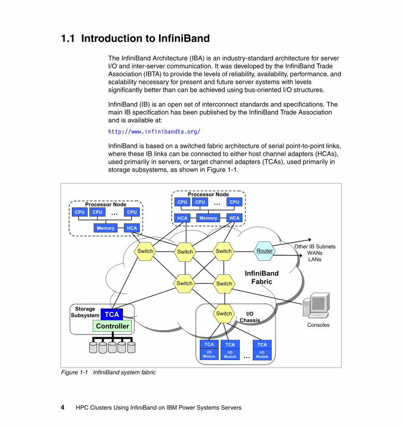
InfiniBand is based on a switched fabric architecture of serial point-to-point links, where these IB links can be connected to either host channel adapters (HCAs), used primarily in servers, or target channel adapters (TCAs), used primarily in storage subsystems, as shown in Figure 1-1.
Figure 1-1 InfiniBand system fabric
SwitchSwitch
CPU CPU CPU…
Memory HCA
Processor Node
HCACPU CPU CPU…
Memory HCA
Processor Node
ControllerTCA
StorageSubsystem
SwitchSwitch Switch RouterOther IB Subnets
WANsLANs
Consoles
InfiniBandFabric
TCAI/O
Module
TCAI/O
Module…
I/OChassis
Switch
TCAI/O
Module
4 HPC Clusters Using InfiniBand on IBM Power Systems Servers

InfiniBand is a point-to-point interconnect developed for today’s systems with the ability to scale to meet the increasing bandwidth demands of today’s computer users.
Features such as zero-copy and Remote Direct Memory Access (RDMA) help reduce processor overhead by directly transferring data from sender memory to receiver memory without involving host processors.
As InfiniBand has grown in popularity among open source communities and scientific labs, in addition to vendor-specific implementations, several versions of the InfiniBand hardware and software stack have been made available. The need for a standardized stack led to the creation of the OpenIB Alliance, now known as the OpenFabrics Alliance, which has created the OpenFabrics Enterprise Distribution (OFED).
The OpenFabrics Alliance (http://www.openfabrics.org/) has merged the work of the OpenIB forum with similar efforts in the 10GigE1 area, and OpenFabrics.org has now released the OpenFabrics Enterprise Distribution, which today is the dominating software distribution for InfiniBand. The OFED stack also includes several higher-level protocols that are not part of the initial IBTA specification.
The InfiniBand physical connection consists of multiple byte lanes. Each individual byte lane is a four wire, 2.5, 5.0, or 10.0 Gbps bi-directional connection. Combinations of link width and byte lane speed allow for overall link speeds from 2.5 Gbps to 120 Gbps. The architecture defines a layered hardware protocol as well as a software layer to manage initialization and the communication between devices. Each link can support multiple transport services for reliability and multiple prioritized virtual communication channels.
To manage the communication, the architecture defines a communication management scheme that is responsible for configuring and maintaining each of the InfiniBand fabric elements. Management schemes are defined for error reporting, link failover, chassis management, and other services to ensure a cohesive communication environment.
The InfiniBand feature set includes:
� Layered protocol: physical, link, network, transport, and upper layers� Packet-based communication� Quality of service
1 10 Gigabit Ethernet
Chapter 1. InfiniBand architecture 5

� Four link speeds (currently):– Single data rate (SDR)– Double data rate (DDR)– Quad data rate (QDR)– Eight data rate (EDR)
� Four link widths (overall speed depends on link type: SDR, DDR, QDR, or EDR):– 1X, 4 wire– 4X, 16 wire– 8X, 32 wire2
– 12X, 48 wire� Passive copper, active copper, or optical (fiber) cable interconnect� Single or dual port adapters� Subnet management protocol� Remote DMA support (RDMA)� Multicast and unicast IP support� Reliable transport method: message queuing� Communication flow control at the link layer and end to end
1.1.1 Terminology
This section defines commonly used IB terms that will be used throughout his book.
� Processor node
– A computer represented by its processors and main memory and managed by a single copy of an operating system.
– Interfaced to an IB fabric via one or more host channel adapters (HCAs).
– Generally, one HCA has two or more ports.
� End nodes
– The ultimate sources and sinks of communication in IBA.
– These may be host systems or devices (network adapter, storage, and so on).
2 8x not available for IBM configurations
6 HPC Clusters Using InfiniBand on IBM Power Systems Servers
� Subnet
– Set of ports and associated links with a common subnet ID
– Contain end nodes, switches, and subnet managers (SMs)
– Managed by a common subnet manager
� I/O unit
– Target channel adapter (TCA) that interfaces to IB fabric
– One or more I/O controllers (IOCs)
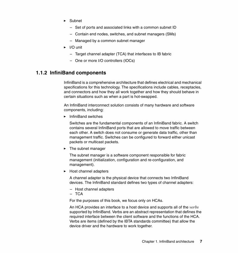
1.1.2 InfiniBand components
InfiniBand is a comprehensive architecture that defines electrical and mechanical specifications for this technology. The specifications include cables, receptacles, and connectors and how they all work together and how they should behave in certain situations such as when a part is hot-swapped.
An InfiniBand interconnect solution consists of many hardware and software components, including:
� InfiniBand switches
Switches are the fundamental components of an InfiniBand fabric. A switch contains several InfiniBand ports that are allowed to move traffic between each other. A switch does not consume or generate data traffic, other than management traffic. Switches can be configured to forward either unicast packets or multicast packets.
� The subnet manager
The subnet manager is a software component responsible for fabric management (initialization, configuration and re-configuration, and management).
� Host channel adapters
A channel adapter is the physical device that connects two InfiniBand devices. The InfiniBand standard defines two types of channel adapters:
– Host channel adapters– TCA
For the purposes of this book, we focus only on HCAs.
An HCA provides an interface to a host device and supports all of the verbs supported by InfiniBand. Verbs are an abstract representation that defines the required interface between the client software and the functions of the HCA. Verbs are items (defined by the IBTA standards committee) that allow the device driver and the hardware to work together.
Chapter 1. InfiniBand architecture 7
� Target channel adapters3
A TCA is a specialized channel adapter (CA). A TCA would be used as a gateway in an data storage device, and generally does not have the full functionality and resources of an HCA. Based on the application, a TCA may have various sets of features. For example, a TCA in a storage device would have a different set of features than a TCA in a printer.
If storage is directly attached to an IB fabric, the IB adapters in the storage devices are called target channel adapters.
� InfiniBand cabling
Today, copper (active or passive) are still the most typical cables, but fiber optic cables are becoming more common.
� Operating system support
Operating system support consists of device drivers, middleware, such as Message Passing Interface (MPI) implementations for HPC applications, support for IP over InfiniBand, and other upper-layer protocols.
1.1.3 Partitioning4
The InfiniBand architecture is intended to be used as a shared fabric to which multiple host systems and their I/O are attached. This is known as the IB fabric.
Partitioning is part of QLogic Virtual Fabrics. Partitioning is considered to be one of the security aspects of Virtual Fabrics. The QLogic Fabric Manager Users Guide, D000007-002 Rev A, has a good overview of Virtual Fabrics.
Imagine the following scenario:
Consider that each host connected to the common fabric has its own I/O bus, and attached to this bus are adapters for node-to-node communication and storage access.
Let us assume that two systems come up at the same time (after a power-on reset). The operating system on each host will perform the bus walk to discover devices. Both system will see all adapters present in the fabric, including those that logically should be private to each of them. Each system will assume ownership of all adapters, accessing them without any synchronization with the other host. This simply does not work.
A mechanism must be put in place that gives host systems enforceable, private access to devices and allows shared resources to be managed. This is where partitioning comes into the game.
3 TCA is not supported for IBM configurations.4 This is not to be confused with IBM System p Logical Partitioning (LPAR).
8 HPC Clusters Using InfiniBand on IBM Power Systems Servers

To ensure that data is sent only to permitted locations, InfiniBand partitioning creates a set of nodes within the fabric that are allowed to communicate with each other. Partitions provide the following features:
� Increase security.� Divide a large cluster into smaller, isolated subclusters.� Map InfiniBand nodes to selected partitions (Virtual Fabrics).
A partition defines a set of InfiniBand nodes that are permitted to communicate with one another. Each node may be part of multiple partitions so that a system administrator can define overlapping partitions as the situation requires.
Partition membersA partition is a logical entity that only makes sense when it has at least two members. Without members, a partition does not have meaning to the IB fabric. Ports are added to the partition and become members of that partition. Each port may be part of multiple partitions so that you can define overlapping partitions as the situation requires.
Membership typesA partition contains a group of members, but different types of members can exist within a single partition. Partition membership allows even further control because it defines communication within the members of that group, not just outside of it.
There are two types of partition memberships:
� Full membership � Limited membership
A full-membership partition member can communicate with all other partition members including other full members and limited members. A limited-membership partition member cannot communicate with other limited-membership partition members. However, a limited partition member can communicate with a full member. QLogic Fabric Manager configuration treats this as FullMember and Member within a Virtual Fabric.
At the time that a port member is added to the partition you must decide whether that particular port will have full or limited membership.
Chapter 1. InfiniBand architecture 9
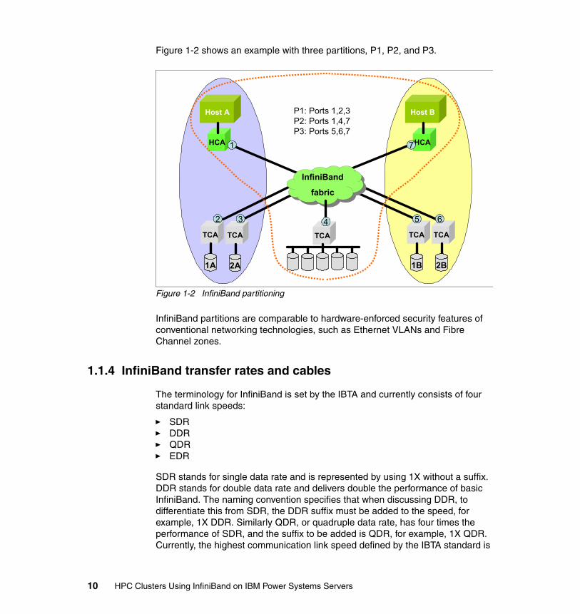
Figure 1-2 shows an example with three partitions, P1, P2, and P3.
Figure 1-2 InfiniBand partitioning
InfiniBand partitions are comparable to hardware-enforced security features of conventional networking technologies, such as Ethernet VLANs and Fibre Channel zones.
1.1.4 InfiniBand transfer rates and cables
The terminology for InfiniBand is set by the IBTA and currently consists of four standard link speeds:
� SDR� DDR� QDR � EDR
SDR stands for single data rate and is represented by using 1X without a suffix. DDR stands for double data rate and delivers double the performance of basic InfiniBand. The naming convention specifies that when discussing DDR, to differentiate this from SDR, the DDR suffix must be added to the speed, for example, 1X DDR. Similarly QDR, or quadruple data rate, has four times the performance of SDR, and the suffix to be added is QDR, for example, 1X QDR. Currently, the highest communication link speed defined by the IBTA standard is
InfiniBand
fabric
InfiniBand
fabric
TCA
Host A
HCA
Host B
HCA
TCA
2A
TCA
1A
TCA
2B
TCA
1B
7
2 3 4 5 6
1
P1: Ports 1,2,3P2: Ports 1,4,7P3: Ports 5,6,7
10 HPC Clusters Using InfiniBand on IBM Power Systems Servers
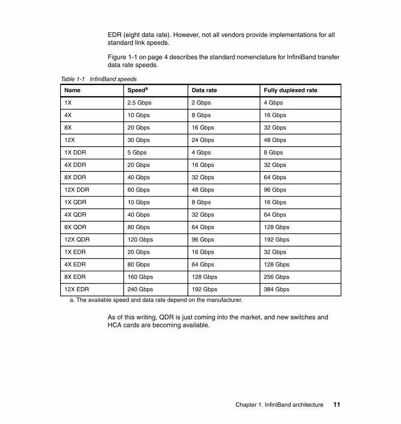
EDR (eight data rate). However, not all vendors provide implementations for all standard link speeds.
Figure 1-1 on page 4 describes the standard nomenclature for InfiniBand transfer data rate speeds.
Table 1-1 InfiniBand speeds
As of this writing, QDR is just coming into the market, and new switches and HCA cards are becoming available.
Name Speeda
a. The available speed and data rate depend on the manufacturer.
Data rate Fully duplexed rate
1X 2.5 Gbps 2 Gbps 4 Gbps
4X 10 Gbps 8 Gbps 16 Gbps
8X 20 Gbps 16 Gbps 32 Gbps
12X 30 Gbps 24 Gbps 48 Gbps
1X DDR 5 Gbps 4 Gbps 8 Gbps
4X DDR 20 Gbps 16 Gbps 32 Gbps
8X DDR 40 Gbps 32 Gbps 64 Gbps
12X DDR 60 Gbps 48 Gbps 96 Gbps
1X QDR 10 Gbps 8 Gbps 16 Gbps
4X QDR 40 Gbps 32 Gbps 64 Gbps
8X QDR 80 Gbps 64 Gbps 128 Gbps
12X QDR 120 Gbps 96 Gbps 192 Gbps
1X EDR 20 Gbps 16 Gbps 32 Gbps
4X EDR 80 Gbps 64 Gbps 128 Gbps
8X EDR 160 Gbps 128 Gbps 256 Gbps
12X EDR 240 Gbps 192 Gbps 384 Gbps
Chapter 1. InfiniBand architecture 11

Different InfiniBand cables are required for the different performance levels of InfiniBand. As illustrated in Figure 1-3, higher bandwidth solutions require cables with more pairs of wire. The speed designation is based on the numbers of send and receive pairs in each interface. For example, a 1X InfiniBand cable has one pair of send and one pair of receive wires, while a 12X connection has 12 send and 12 receive pairs.
Figure 1-3 Internal structure of InfiniBand cables
For more information about all IBM supported IB cables refer to Chapter 2, “High performance computing hardware components using InfiniBand” on page 41.
1.2 I/O architecture: bus versus fabric
The shared bus architecture is the most common I/O interconnect architecture today, despite numerous drawbacks, such as contention and congestion. Clusters and networks require systems with high-speed, fault-tolerant interconnects that cannot be supported properly using a bus architecture. The following sections present the highlights of both I/O architectures.
12 HPC Clusters Using InfiniBand on IBM Power Systems Servers
1.2.1 Shared bus architecture
In a shared bus architecture, the bandwidth of the bus is divided among all devices sharing the same bus. If any one device consumes all the bandwidth on the bus, none of the other devices on that bus can communicate (bandwidth contention). Bus configurations can have severe electrical signal, mechanical, and power issues. Parallel bus requires many pins for each connection, occupying large amounts of system board real estate. PCI-X is an example of shared bus architecture.
At high bus frequencies, the distance of each signal is limited to short traces on the system board. In a slot-based system with multiple card slots, bus termination is difficult to control and can cause problems if not designed properly. These limitations make shared bus architectures undesirable for applications that demand high performance and high scalability.
Shared buses can be extended by using a technique called bridging. This allows for the implementation of more slots, but can have negative bandwidth implications. Latency and congestion increase with each addition of a bus bridge.
1.2.2 Fabric architecture
Fabric is a communication architecture based on a hardware infrastructure consisting in external (device) ports connected to microelectronics switching elements, which are interconnected in a matrix that provides full port bandwidth communication between any of the ports connected to the fabric.
An example of switch fabric is the Fibre Channel. In the Fibre Channel switched fabric topology (called FC-SW), devices are connected to each other through one or more Fibre Channel switches. This topology allows the connection of up to the theoretical maximum of 16 million devices, limited only by the available address space. Multiple switches in a fabric usually form a mesh network, with devices being on the edges (leafs) of the mesh.
1.2.3 Example: SCSI bus versus SAN fabric
Used for the same purpose as the SAN (access to storage), Small Computer System Interface (SCSI) is representative for bus architecture. In SCSI implementation, all devices (nodes, storage) share the same bus (cable).
Chapter 1. InfiniBand architecture 13
There are two differences between the SCSI bus and a SAN fabric:
� Multiple access
In a SAN, multiple servers to access multiple storage devices while in SCSI storage can only be accessed by servers directly attached to the SCSI bus. In contrast, only two devices can communicate at one time over the shared SCSI bus. Thus, even if multiple systems and storage devices are connected to the same bus, only two of these (one server and one storage device) can communicate at a time.
� Distance limitations
Due to its parallel electrical bus architecture, SCSI has always had bus-length limitations. With the gain in speed (SCSI-3, Ultra SCSI) also comes the disadvantage of a shorter cable length. For example, the Ultra SCSI cable length is limited to 1.5 m (5 ft.), with up to four devices attached.
In contrast, Fibre Channel uses a serial communication (copper, fiber) that overcomes distance limitations. For example, SAN implementations using short wave (SW) multimode optical cables support cable lengths of up to 500 m. Furthermore, long wave (LW) single optical cables provide for communication distances up to 10 km.
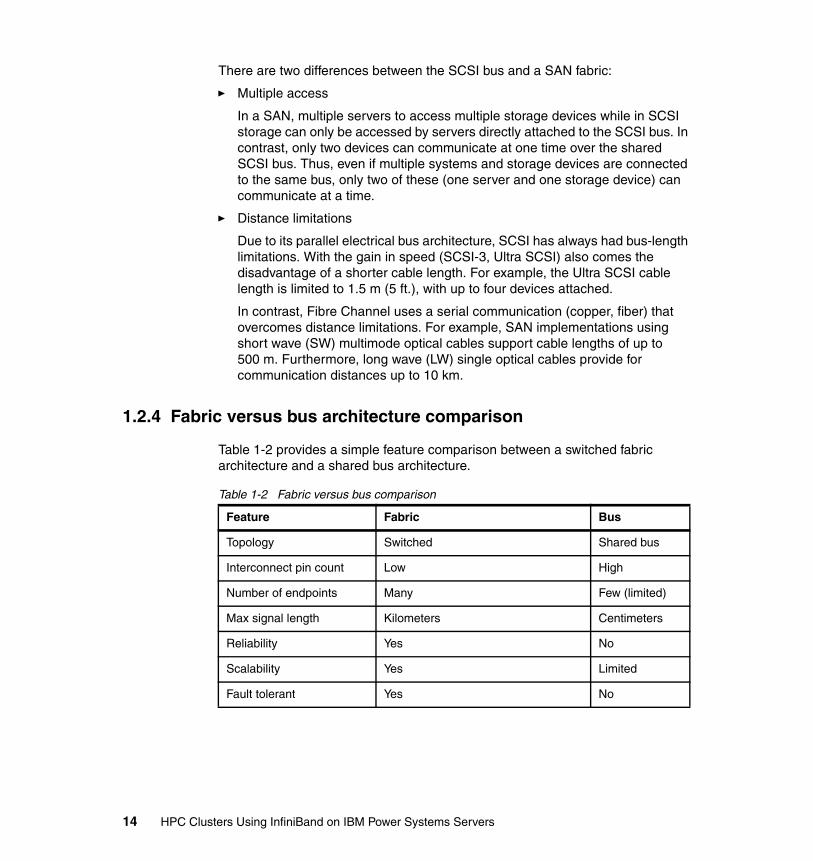
1.2.4 Fabric versus bus architecture comparison
Table 1-2 provides a simple feature comparison between a switched fabric architecture and a shared bus architecture.
Table 1-2 Fabric versus bus comparison
Feature Fabric Bus
Topology Switched Shared bus
Interconnect pin count Low High
Number of endpoints Many Few (limited)
Max signal length Kilometers Centimeters
Reliability Yes No
Scalability Yes Limited
Fault tolerant Yes No
14 HPC Clusters Using InfiniBand on IBM Power Systems Servers

A fabric architecture allows for a many-to-many type of communication, which has several benefits:
� Improved resiliency to a component failure
� Ability to communicate over more than one path at one time
� Allows for multiple endpoints to communicate with each other without interfering with each other
Generally, fabrics are more resilient and have less contention for resources. An important consideration in the design of these systems is that a fabric can be extended by adding another fabric unit as a whole, and with careful planning and implementation this can greatly enhance the capacity of the entire fabric. Using this feature, fabrics can scale virtually limitlessly, whereas bus configurations can only scale within the hardware boundaries of a server or storage subsystem.
Fabric architecture is also more complex to operate, and as a result, it tends to be more expensive to acquire and manage. In most situations, cost and complexity are far outweighed by the performance and reliability of these devices.
1.2.5 InfiniBand enablers
New in-server interconnects such as PCI Express and IBM GX bus allow systems to better exploit InfiniBand’s capabilities.
PCI Express (PCIe)PCI Express architecture continuous development offers ever greater amounts of bandwidth to supply today’s faster processors with the data that they need to deliver faster performance and better user experiences. PCI Express is a standard 64-bit shared bus peripheral interconnect that supports up to six endpoints (PCI devices) on a single bus. Although an industry standard, PCIe is not the choice interface for InfiniBand devices in IBM Power Systems servers.
IBM GX busIBM GX bus adapters use a 64-bit fully meshed loop topology implemented in IBM Power Systems servers to deliver high-bandwidth and low-latency communications. GX bus has a theoretically unlimited ability to interconnect devices. For example, the IBM Power Systems model 595 supports up to 32 GX bus connections. The bandwidth of these systems is impressive, and its low latency makes this a natural choice for being the interface to use for InfiniBand adapters.
Chapter 1. InfiniBand architecture 15
1.2.6 InfiniBand: bandwidth out of the box
A fundamental concept of the InfiniBand architecture is that of bandwidth out of the box. InfiniBand has the ability to deliver data to devices outside the server central electronic complex (CEC) at speeds generally only seen inside the server backplane. This performance allows for new services to be offered, such as video on demand, and traditional services, like Web services, to deliver new levels of performance and serviceability.
Historically, bandwidth decreases as distance away from the CPU increases. For example, typical CPU-to-memory communication is measured in the tens of gigabytes (GB) per second range of throughput, while network technologies commonly deliver only megabits to gigabits (Mb, Gb) per second of throughput and have substantial overhead that lowers their utility. InfiniBand delivers GBps range performance over distances measured in kilometers with only a small overhead.
In the current state of the art processors they are able to communicate with memory at speeds up to 30 GBps, but PCI-X and other bus interconnects also have limited bandwidth, typically 0.25 to 1 GB per second. The GX bus adapter implemented in the IBM Power Systems servers can sustain transfer rates up to 320 GBps.
1.3 Application clustering
The Internet today has evolved into an immense global infrastructure supporting numerous applications and services. Each of these applications and services must support an ever-increasing volume of data while delivering higher and higher availability and faster response times. Service providers are, in turn, experiencing tremendous pressure to support these application requirements. At the same time as trying to deliver this improved performance, they are trying to create new offerings such as quality of service (QoS) and improved security.
Service providers have appeared to support the outsourcing of e-commerce, e-marketing, and other e-business-related activities, specializing in delivering these high-demand Internet-based applications. Providers must now be able to offer highly reliable services that offer the ability to dramatically scale the processing and communication infrastructure capabilities in a short period of time to accommodate the explosive growth of application demand in situations such as major news events or new product releases. Clustering techniques have evolved as the preferred mechanism to support these requirements. A cluster is simply a group of servers connected by load-sharing/balancing elements working in parallel to serve a particular application.
16 HPC Clusters Using InfiniBand on IBM Power Systems Servers

InfiniBand simplifies application cluster connections by unifying networks with a feature-rich managed architecture. The InfiniBand switched architecture provides native cluster connectivity, thus supporting scalability and reliability for clustering. Devices can be added and multiple paths can be utilized with the addition of switches to the fabric. High-priority transactions between devices can be processed ahead of lower-priority items through the QoS mechanisms built into InfiniBand.
Application cluster features such as Sockets Direct Protocol and RDMA allow integrated products to communicate at much higher rates of speed.
1.4 Clustering with InfiniBand
The history of cluster computing is best captured by a footnote in Gregory Pfister's book In Search of Clusters5: “Virtually every press release from DEC mentioning clusters says 'DEC, who invented clusters…'. IBM did not invent them either. In fact, customers invented clusters, as soon as they could not fit all their work on one computer, or needed a backup. The date of the first is unknown, but it would be surprising if it was not in the 1960s, or even late 1950s.”
So the fact is that cluster computing is mainly used as application requirements increase so much that the performance of a single system is no longer sufficient for running such applications efficiently.
Throughout this book we limit the scope of the definition of a cluster to a computer system comprising a collection of independent nodes, where each node is a system in its own right capable of independent operation and connected by a fast interconnect.
1.4.1 The interconnect
In order to achieve the highest performance capabilities of a cluster, data must be able to move between computers at (or close to) the speed with which it moves within the computer itself. In fact, several applications today take advantage of node-to-node direct memory communication, also known as Remote Direct Memory Access, which basically shares memory physically located in different computers. With RDMA-enabled applications, a high-performance interconnect is a requirement.
Depending on the specific application, the interconnect technology used in a cluster can have tremendous impact on the overall application performance.
5 ISBN 0138997098
Chapter 1. InfiniBand architecture 17
However, some applications, like embarrassingly parallel applications, require very little interprocessor communication.
Parallel applications usually break the problem apart into smaller tasks. Each server is engaged to solve its own piece (task) of the overall problem. The tasks’ results are then assembled and fed back to the application. In these environments, high-speed interconnect technologies do not add tremendous value because the performance of the application is tied more closely to the computing capability of the individual server (processing power) rather than of the entire cluster.
Other applications, however, rely on the tight integration of servers to all work together to simultaneously solve a problem or set of problems (that is, barrier computing). These applications leverage the computing elements to work in parallel. Many of them even leverage a common pool of available memory that spans multiple servers. These applications rely on servers having the ability to move tremendous amounts of data at very high speeds (equivalent to the bus communication inside an individual server) between the nodes.
Networking technologies (such as Ethernet) serve a general purpose. They move packets of data around a network and connect computers and other devices to one another. And while the technology has evolved significantly in the last 25 years, a set of standards has emerged. Both Ethernet (as the transport) and Internet Protocol (IP) (as the protocol) have emerged as the worldwide standard methods of connecting devices. However, due to its more general nature, the Ethernet simply does not provide all the requirements for a high-performance computing environment.
1.4.2 Bandwidth versus latency
The InfiniBand specification defines a switched, high-bandwidth, low-latency fabric for both interprocess and I/O communication. In order to understand what this means, we take a closer look at the terms bandwidth and latency.
BandwidthBandwidth is normally expressed in bits per second. It is the amount of data that can be transferred during a second. Although the theoretical peak bandwidth of a
Note: For example, with the Linpack benchmark suite the tasks can be fairly independent, that is, there is no need for massive communication between tasks running on different nodes. Thus Linpack does not really benefit from the IB infrastructure or any other high-speed, low-latency interconnect for that matter.
18 HPC Clusters Using InfiniBand on IBM Power Systems Servers
network connection is fixed according to the technology used, the actual bandwidth that you will obtain varies over time and is affected by high latencies.
Bandwidth and latency are connected. If the bandwidth is saturated then congestion occurs and latency increases. However, if the bandwidth of a circuit is not at peak, the latency will not decrease. Generally, within the boundaries of the same technology (for example, Ethernet) bandwidth can be increased but latency cannot be decreased. Latency is the function of the electrical characteristics of the underlying hardware (for example, circuits in switches).
LatencyLatency is delay. Latency is normally expressed in milliseconds or microseconds. One of the most common methods to measure latency is to use a form of control messaging protocol (for example, Internet Control Message Protocol (ICMP), with its most common implementation, ping). A small packet of data, typically 32 bytes, is sent to a host and the round-trip time (RTT)—the time that it takes for the packet to leave the source host, travel to the destination host, and return back to the source host—is measured.
Excessive latency creates bottlenecks that prevent data from filling the network pipe, thus decreasing effective bandwidth. The impact of latency on network bandwidth can be temporary (lasting a few seconds) or persistent (constant) depending on the source of the delays.
Low-latency links are important for message-passing applications (Message Passing Interface (MPI)). Typically, several instances of the same MPI process will run on different nodes and depend on data passed from other nodes to complete their computation. Latency is therefore one of the performance-limiting factors to be taken into account. For example, the latency of Gigabit Ethernet tends to be of the order of 100 microseconds or more, whereas InfiniBand latency is of the order of 1 to 2 microseconds. For more information about MPI over InfiniBand refer to 3.3.2, “HPC application software” on page 114.
1.4.3 Why clusters exploit InfiniBand
HPC clusters can provide cost-effective computational power for high-end, floating point-intensive scientific and engineering problems and data-intensive commercial tasks. Common uses of HPC clusters include:
� Weather modeling
� Seismic analysis for oil exploration
� Computational fluid dynamics for aerodynamic simulation in the automotive and aircraft industries
Chapter 1. InfiniBand architecture 19
� Bioinformatics and protein folding for molecular modeling in biomedical research
� Data mining and finance modeling for business analysis
InfiniBand clusters have demonstrated linear scalability in both commercial and technical applications, where thousands of nodes coupled together can provide aggregate application-level performance roughly equivalent to the number of nodes times the power of a single node. This is achieved thanks to InfiniBand's unique bandwidth, latency, and scalability characteristics.
Many industries, including defense, energy, financial services, media, oil and gas exploration, and manufacturing, already take advantage of InfiniBand.
Advantages of InfiniBand are:
� Increased application performance:
– Higher bandwidth– Lower latency– Reduced CPU utilization due to protocol offloading
� Standard-based interconnect used for:
– Commercial clustering– Technical clustering
� Increased data center reliability by using:
– Switched fabrics– Multiple levels of redundancy
� Enhanced node density (less datacenter space requirements):
– Single fabric for clustering, Ethernet, and FC SAN connection– Dense rack-mounted servers
The InfiniBand offering and market has grown significantly and is now available from all of major system vendors.
1.5 InfiniBand communication and management architecture overview
This section provides an overview of the high-level InfiniBand software concepts and terms that are used in later sections and chapters.
As discussed earlier in this chapter, the InfiniBand architecture is a fabric communication and management infrastructure supporting both I/O and
20 HPC Clusters Using InfiniBand on IBM Power Systems Servers
interprocessor communications (IPC) for one or more computer systems. The fabric allows many devices to concurrently communicate with high bandwidth and low latency in a protected, remotely managed environment. An end node can communicate over a host channel adapter utilizing multiple ports and paths through the InfiniBand fabric.
The multiplicity of IBA ports and paths through the network are exploited for both fault tolerance and increased data throughput. The combination of the InfiniBand's communication and management infrastructure offloads much of the CPU and I/O communications to the hardware, which allows multiple concurrent communications without the traditional overhead associated with communicating protocols.
1.5.1 Communication
InfiniBand operations are based on the ability to queue instructions to be executed by the communication hardware. There is a work queue for send operations and a work queue for receive operations. The send queue holds instructions that determine how data is to be transferred between the requestor’s memory and the receiver’s memory. The receive queue holds instructions telling where to store data that has been received.
If a request is submitted, its instruction is placed on the appropriate work queue. The channel adapter then executes it in the order presented (first in, first out, or FIFO).
A host channel adapter represents the local channel interface. A channel interface is a combination of hardware, firmware, and software that provides InfiniBand service to a host.
In the case of a send operation, the channel adapter interprets the type of work, creates a message, segments it (if needed) into multiple packets, adds the routing information, and sends the packets to a port. Port logic is now responsible for sending the packets across the link through the fabric to its destination. When the packets arrive at the destination, the receiving port logic validates the packet, and the channel adapter puts it on the receive queue and executes it. If requested, the channel adapter creates an acknowledgement and sends it back to data source.
Queue pair (QP)In InfiniBand, the send work queue (SQ) and the receive work queue (RQ) are paired to form what is called a queue pair (QP) and are always created as a pair.
Chapter 1. InfiniBand architecture 21
The QP is a memory-based abstraction where communication is achieved through direct memory-to-memory transfers between applications and devices. A connection is made by linking a QP on local system (local QP) to a QP on a remote system (remote QP). Applications do not share queue pairs. Once you set them up, you can manage them at the application level without incurring the overhead of system calls (thus offloading the main processor).
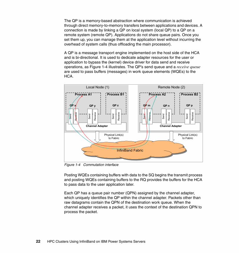
A QP is a message transport engine implemented on the host side of the HCA and is bi-directional. It is used to dedicate adapter resources for the user or application to bypass the (kernel) device driver for data send and receive operations, as Figure 1-4 illustrates. The QP’s send queue and a receive queue are used to pass buffers (messages) in work queue elements (WQEs) to the HCA.
Figure 1-4 Commutation interface
Posting WQEs containing buffers with data to the SQ begins the transmit process and posting WQEs containing buffers to the RQ provides the buffers for the HCA to pass data to the user application later.
Each QP has a queue pair number (QPN) assigned by the channel adapter, which uniquely identifies the QP within the channel adapter. Packets other than raw datagrams contain the QPN of the destination work queue. When the channel adapter receives a packet, it uses the context of the destination QPN to process the packet.
Channel Adapter
Rec
eive
Sen
d
Rec
eive
Sen
d
QP x QP y
Process A1
Rec
eive
Sen
d
QP z
Process B1
Physical Link(s)to Fabric
Local Node (1)
Channel Adapter
Rec
eive
Sen
d
Rec
eive
Sen
d
QP m QP n
Process A2
Rec
eive
Sen
d
QP p
Process B2
Physical Link(s)to Fabric
Remote Node (2)
InfiniBand FabricInfiniBand Fabric
22 HPC Clusters Using InfiniBand on IBM Power Systems Servers
There are two special QPs that are used for management:
� QP0 is used to manage subnet management packets and is managed by subnet management agent (SMA, implemented in the device driver). The SMA handles all packets received on QP0 and responds to the actions specified in the subnet management packet (SMP).
� QP1 is a general-services interface (GSI) that is used by the InfiniBand Connection Manager (ICM) and handles general management packets.
VerbsA host channel adapter provides an interface to a host device and supports verbs defined to InfiniBand. Verbs describe the service interface between a host channel adapter and the software that supports it. Verbs allow the device driver and the hardware to work together. A verb is used to define the functionality of the HCA and a verb consumer refers to the direct user of the verb.
Verb layerThe verb layer is the IBA specification that describes what the application interface (API) must support without rigorously defining the API and is defined for application and kernel users of IB. The verb layer has two main responsibilities:
� Identifying, initializing, and controlling the HCA device.
HCA verbs are:
– Open.– Query.– Modify.– Close.
� Performing the management of hardware resources, such as queue pairs, completion queues (CQs), and memory registration resources for performing translation and protection management.
– QP verbs: • Create.• Modify.• Query.• Destroy.• Get Special QP.
– CQ verbs: • Create.• Query.• Resize.• Destroy.• Poll.
Chapter 1. InfiniBand architecture 23
– Address handle (AH) verbs: • Create.• Modify.• Query.• Destroy.
– Memory region (MR) verbs: • Register.• Query.• Reregister.• Deregister.
– Multicast (MC) verbs: • Create.• Modify.• Query.• Destroy.
– Protection domain (PD) verbs: • Allocate.• Deallocate.
Transport semantics and servicesAs mentioned previously in “Queue pair (QP)” on page 21, communication in InfiniBand is accomplished using a queue-based model. Sending and receiving end-points must establish a QP, which consists of SQ and RQ. Send and receive work requests (WRs) are then placed onto these queues for processing by the InfiniBand network stack. Completion of these operations is indicated by InfiniBand lower layers by placing completed requests in the CQ. To receive a message on a QP, a receive buffer must be posted to that QP. Buffers are consumed in a FIFO ordering. The transport semantics and services that make this possible are described below.
Communication semanticsInfiniBand communication semantics support both channel (send/receive) and memory semantics.
Channel semantics Channel semantics are send and receive operations that are common in traditional interfaces, such as sockets, where both sides must be aware of communication.
Basically, each send request has a corresponding receive request at the remote end. Thus, there is a one-to-one correspondence between every send and receive operation. Receive operations require buffers posted on each of the communicating QP, which amount to a large number. In order to allow sharing of
24 HPC Clusters Using InfiniBand on IBM Power Systems Servers
communication buffers, IBA allows the use of SRQs, in which multiple QPs have a common receive queue.
Memory semantics Memory semantics are one-sided operations where one host can access memory from a remote node without a posted receive. This semantic type is typically referred to as Remote Direct Memory Access, which supports remote write and read atomic operations.
RDMA operations do not require a receive descriptor at the remote end and are transparent to it. For RDMA, the send request itself contains the virtual addresses for both the local transmit buffer and the receive buffer on the remote end. RDMA operations are available with the RC transport. IBA also defines an additional operation: RDMA write with immediate data. In this operation, a sender can send a limited amount of immediate data along with a regular RDMA operation.
In general, both InfiniBand communication semantics require that the memory used for communication be pinned and stays pinned throughout the life of the queue pair.
Transport servicesInfiniBand supports the following transport services:
� Reliable connection (RC)� Reliable datagram (RD)� Unreliable connection (UC) � Unreliable datagram (UD)
However, in an HPC environment the most commonly used transport services are RC and UD.
Connection-oriented reliable connection (RC)The RC transport specified by IBA specifies the RC transport layer as a reliable communication layer. In this transport layer, both channel and memory semantics are supported. The communication packets are completely managed by the RC transport layer. Furthermore, since the RC transport layer guarantees reliability and in-order delivery of data, it is the typical transport service for implementing MPI over InfiniBand.
As a connection-oriented service, a QP with RC transport must be dedicated to communicating with only one other QP. The RC transport provides almost all the features available in InfiniBand, most notably reliable send/receive, RDMA, and Atomic operations.
Chapter 1. InfiniBand architecture 25

Connection-less unreliable datagram (UD)The UD transport specified by IBA supports only the channel-based communication semantics. The basic communication is achieved in the UD layer by exchanging network MTU-sized datagrams. These datagrams can be sent to a UD QP by any other UD QP in the network. An explicit connection between the two QPs in not needed. The reliability and order of delivery of these datagrams is not guaranteed by IBA and must be managed by the application.
AddressingEach end node contains one or more channel adapters and each channel adapter contains one or more ports. Additionally, each channel adapter contains a number of queue pairs. Each queue pair has a queue pair number (QPN) assigned by the channel adapter, which uniquely identifies the QP within the channel adapter. Packets other than raw datagrams contain the QPN of the destination work queue. When the channel adapter receives a packet, it uses the context of the destination QPN to process the packet.
LID/LMCA port has a local 16-bit identifier (LID) assigned by the local subnet manager. Within the subnet, LIDs are unique. Switches use the LID to route packets within the subnet. The local subnet manager configures routing tables in switches based on LIDs and where that port is located with respect to the specific switch. Each packet contains a source LID (SLID) that identifies the port that injected the packet into the subnet and a destination LID (DLID) that identifies the port where the fabric is to deliver the packet.
IBA also provides for multiple virtual ports within a physical port by defining a LID mask count (LMC). The LMC specifies the number of least significant bits of the LID that a physical port masks (ignores) when validating that a packet DLID matches its assigned LID. Those bits are not ignored by switches. Therefore, the subnet manager can program different paths through the fabric based on those least significant bits.
26 HPC Clusters Using InfiniBand on IBM Power Systems Servers
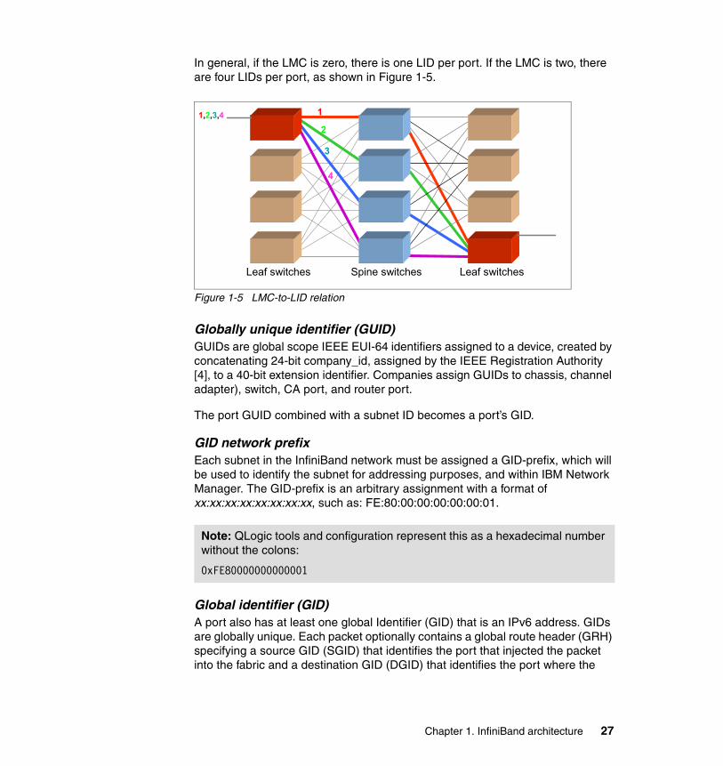
In general, if the LMC is zero, there is one LID per port. If the LMC is two, there are four LIDs per port, as shown in Figure 1-5.
Figure 1-5 LMC-to-LID relation
Globally unique identifier (GUID)GUIDs are global scope IEEE EUI-64 identifiers assigned to a device, created by concatenating 24-bit company_id, assigned by the IEEE Registration Authority [4], to a 40-bit extension identifier. Companies assign GUIDs to chassis, channel adapter), switch, CA port, and router port.
The port GUID combined with a subnet ID becomes a port’s GID.
GID network prefixEach subnet in the InfiniBand network must be assigned a GID-prefix, which will be used to identify the subnet for addressing purposes, and within IBM Network Manager. The GID-prefix is an arbitrary assignment with a format of xx:xx:xx:xx:xx:xx:xx:xx, such as: FE:80:00:00:00:00:00:01.
Global identifier (GID)A port also has at least one global Identifier (GID) that is an IPv6 address. GIDs are globally unique. Each packet optionally contains a global route header (GRH) specifying a source GID (SGID) that identifies the port that injected the packet into the fabric and a destination GID (DGID) that identifies the port where the
Note: QLogic tools and configuration represent this as a hexadecimal number without the colons:
0xFE80000000000001
1,2,3,4
Spine switchesLeaf switches Leaf switches
1
2
3
4
Chapter 1. InfiniBand architecture 27
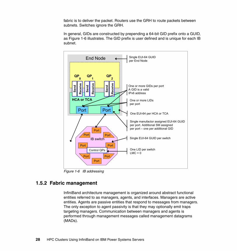
fabric is to deliver the packet. Routers use the GRH to route packets between subnets. Switches ignore the GRH.
In general, GIDs are constructed by prepending a 64-bit GID prefix onto a GUID, as Figure 1-6 illustrates. The GID prefix is user defined and is unique for each IB subnet.
Figure 1-6 IB addressing
1.5.2 Fabric management
InfiniBand architecture management is organized around abstract functional entities referred to as managers, agents, and interfaces. Managers are active entities. Agents are passive entities that respond to messages from managers. The only exception to agent passivity is that they may optionally emit traps targeting managers. Communication between managers and agents is performed through management messages called management datagrams (MADs).
HCA or TCA
End Node
Rec
eive
Send
QP0
Rec
eive
Send
QP1
Rec
eive
Send
QP2
Port Port
Port
Port
PortPort
Port
Port
Port
Port
IB switch
Control QPs
Single EUI-64 GUIDper End Node
One or more GIDs per portA GID is a validIPv6 address
One or more LIDsper port
Single EUI-64 GUID per switch
One LID per switchLMC = 0
Single manufactor assigned EUI-64 GUIDper port. Additional SM assignedper port – one per additional GID
One EUI-64 per HCA or TCA
28 HPC Clusters Using InfiniBand on IBM Power Systems Servers
Managers are conceptual functional entities that affect control over fabric elements or provide for gathering information from fabric elements. In general, they may reside anywhere in the subnet.
Agents are conceptual functional entities present in all IBA channel adapters, switches, and routers that process MADs arriving at the port of the IBA component where they reside. The functionality represented by an agent affects required behavior associated with MADs arriving at the ports with which they are associated.
Interfaces represent a target to which messages may be sent and through which messages will be processed or will be dispatched to an appropriate processing entity. Thus, an interface is a means by which to gain access to the functionality of agents and managers.
Subnet manager Each subnet has at least one subnet manager. Each SM resides on a port of a channel adapter, router, or switch and can be implemented either in hardware or software. When there are multiple SMs on a subnet, one SM will be the master SM. The remaining SMs must be standby SMs. There is only one SM per port.
The master SM is a key element in initializing and configuring an IB subnet. The master SM is elected as part of the initialization process for the subnet and is responsible for:
� Discovering the physical topology of the subnet
� Assigning LIDs to the end nodes, switches, and routers
� Establishing possible paths among the end nodes
� Sweeping the subnet, discovering topology changes, and managing changes as nodes are added and deleted
Every switch, CA, and router has a subnet management agent (SMA) managed by the master SM.
The communication between the master SM and the SMAs, and among the SMs, is performed with subnet management packets (SMPs). SMPs provide a fundamental mechanism for subnet management.
Note: Currently, there are no examples of a hardware (HW) subnet manager, as fabric management has far more requirements than could be solved in a hardware solution. All known subnet managers are software or firmware implementations.
Chapter 1. InfiniBand architecture 29
Subnet administration (SA)The subnet agent on each entity collects and provides information that end nodes require for correct operation within a subnet. Such information includes paths between end nodes, notification of events, service attributes, and so on.
Subnet administration is one of the management classes associated with the general services (GS) defined by the IBA architecture. Every IBA subnet must provide an SA with the required functionality. Through the use of subnet administration class MADs, SA provides access to and storage of information of several types:
� Information that end nodes require for operation in a subnet: Such information includes paths between end nodes, notification of events, and so on.
� Information representing policies and software configuration for the cluster such as partitioning, QOS (SLs and VLs), Virtual Fabrics, management security (M_Keys), and so on.
� Information that may be useful to other management entities such as standby SMs and QLogic FastFabric Tools, which may, for example, wish to use it to maintain synchronization with the master SM. Such information includes subnet topology data, switch forwarding tables, and so on.
SA includes a reliable multipacket data transfer protocol, required because the information sent to or retrieved by SA in many cases is larger than will fit into a single MAD unreliable datagram. All of the data provided by the SA is collected by or configured into the SM. SA must therefore have a close relationship with the master SM. In fact, the SA may be considered as being part of the SM.
Performance manager (PM)The performance manager provides methods that enable a manager to retrieve performance statistics and error information from the IB components. Performance quantities are divided into two classes:
� Mandatory for all ports of all nodes (TCAs, HCAs, switches, and routers): These quantities are deemed necessary to support fundamental instrumentation and performance analysis of a multivendor InfiniBand fabric.
� Optional: These quantities may be implemented at the vendor’s discretion, and are described here as an aid to standardization.
Baseboard manager (BM)The baseboard manager manages the physical hardware, like environmentals, vital product data, LEDs, and so on. This is considered synonymous with system management, as opposed to subnet management.
30 HPC Clusters Using InfiniBand on IBM Power Systems Servers
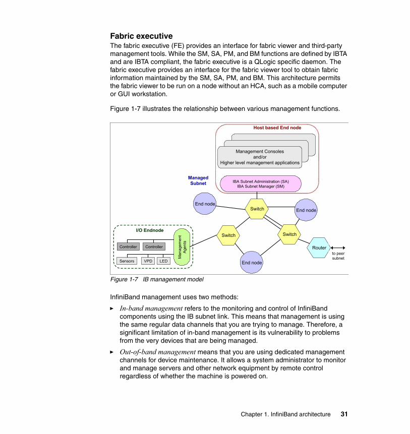
Fabric executiveThe fabric executive (FE) provides an interface for fabric viewer and third-party management tools. While the SM, SA, PM, and BM functions are defined by IBTA and are IBTA compliant, the fabric executive is a QLogic specific daemon. The fabric executive provides an interface for the fabric viewer tool to obtain fabric information maintained by the SM, SA, PM, and BM. This architecture permits the fabric viewer to be run on a node without an HCA, such as a mobile computer or GUI workstation.
Figure 1-7 illustrates the relationship between various management functions.
Figure 1-7 IB management model
InfiniBand management uses two methods:
� In-band management refers to the monitoring and control of InfiniBand components using the IB subnet link. This means that management is using the same regular data channels that you are trying to manage. Therefore, a significant limitation of in-band management is its vulnerability to problems from the very devices that are being managed.
� Out-of-band management means that you are using dedicated management channels for device maintenance. It allows a system administrator to monitor and manage servers and other network equipment by remote control regardless of whether the machine is powered on.
End node
Management Consolesand/or
Higher level management applications
IBA Subnet Administration (SA)IBA Subnet Manager (SM)
Controller Controller
Man
agem
ent
Age
nts
Sensors VPD LED
I/O Endnode
ManagedSubnet
Host based End node
to peersubnet
Switch
Switch Switch
Router
End node
End node
Chapter 1. InfiniBand architecture 31
Management datagrams (MAD)A number of MAD management classes are distinguished in the IBA management model. The classes that are relevant for our purpose are the subnet management and the subnet administration classes:
� The subnet management class represents mainly the body of activity associated with discovering, initializing, and maintaining an IBA subnet. The manager and agent associated with this class are called, respectively, the subnet manager and the subnet management agent. The MADs of this class are called subnet management packets (SMPs).
� The subnet administration class provides a means for management entities and applications to obtain information about fabric configuration and operation. The subnet administrator is part of the subnet manager and its class is separated from the subnet management only for commodity. The MADs of this class will be referred to as SA MADs.
All the management classes except for the subnet management class are referred to as general services. MADs defined for GS are referred to as general management packets (GMPs).
Subnet management packets The communication between the master SM and the SMAs, and among the SMs, is performed with subnet management packets. There are two types of SMPs:
� LID-routed SMPs are forwarded through the subnet by switches based on the LID of the destination.
� Directed route SMPs are forwarded based on a vector of port numbers that define a path through the subnet. Directed route SMPs are used to implement several management functions, in particular, SM fabric discovery and configuration before the LIDs for all the nodes have been discovered or assigned. Directed-route SMPs are forwarded based on a vector of port numbers and optionally LIDs.
Management interfacesTwo required interfaces to management entities are specified based upon two well-known QPs—the subnet Management Interface (QP0) and the general service interface (QP1).
QP0 and QP1 have unique semantics with respect to the processing of messages specifying one of them at the destination QP. Implementations of QP0 and QP1 are not required to follow the semantics associated with the other standard queue pairs. They could be regular interfaces to the verbs (which is referred to as above the verbs) using the usual verb mechanisms or they could be
32 HPC Clusters Using InfiniBand on IBM Power Systems Servers
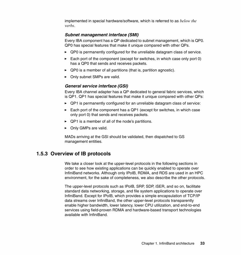
implemented in special hardware/software, which is referred to as below the verbs.
Subnet management interface (SMI)Every IBA component has a QP dedicated to subnet management, which is QP0. QP0 has special features that make it unique compared with other QPs.
� QP0 is permanently configured for the unreliable datagram class of service.
� Each port of the component (except for switches, in which case only port 0) has a QP0 that sends and receives packets.
� QP0 is a member of all partitions (that is, partition agnostic).
� Only subnet SMPs are valid.
General service interface (GSI)Every IBA channel adapter has a QP dedicated to general fabric services, which is QP1. QP1 has special features that make it unique compared with other QPs:
� QP1 is permanently configured for an unreliable datagram class of service:
� Each port of the component has a QP1 (except for switches, in which case only port 0) that sends and receives packets.
� QP1 is a member of all of the node’s partitions.
� Only GMPs are valid.
MADs arriving at the GSI should be validated, then dispatched to GS management entities.
1.5.3 Overview of IB protocols
We take a closer look at the upper-level protocols in the following sections in order to see how existing applications can be quickly enabled to operate over InfiniBand networks. Although only IPoIB, RDMA, and RDS are used in an HPC environment, for the sake of completeness, we also describe the other protocols.
The upper-level protocols such as IPoIB, SRP, SDP, iSER, and so on, facilitate standard data networking, storage, and file system applications to operate over InfiniBand. Except for IPoIB, which provides a simple encapsulation of TCP/IP data streams over InfiniBand, the other upper-level protocols transparently enable higher bandwidth, lower latency, lower CPU utilization, and end-to-end services using field-proven RDMA and hardware-based transport technologies available with InfiniBand.
Chapter 1. InfiniBand architecture 33
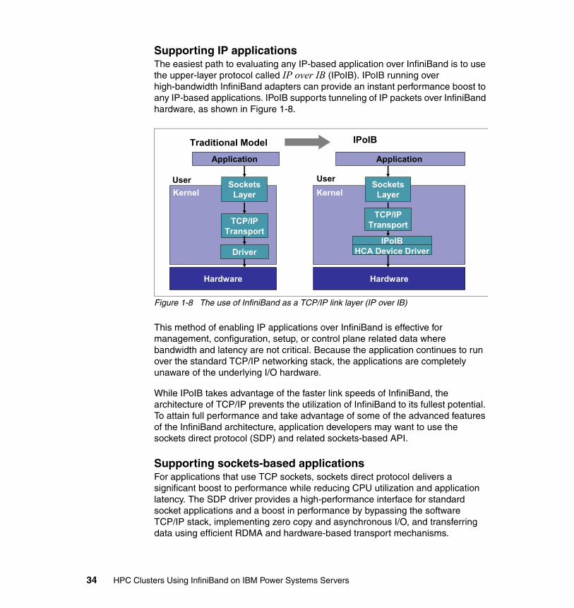
Supporting IP applicationsThe easiest path to evaluating any IP-based application over InfiniBand is to use the upper-layer protocol called IP over IB (IPoIB). IPoIB running over high-bandwidth InfiniBand adapters can provide an instant performance boost to any IP-based applications. IPoIB supports tunneling of IP packets over InfiniBand hardware, as shown in Figure 1-8.
Figure 1-8 The use of InfiniBand as a TCP/IP link layer (IP over IB)
This method of enabling IP applications over InfiniBand is effective for management, configuration, setup, or control plane related data where bandwidth and latency are not critical. Because the application continues to run over the standard TCP/IP networking stack, the applications are completely unaware of the underlying I/O hardware.
While IPoIB takes advantage of the faster link speeds of InfiniBand, the architecture of TCP/IP prevents the utilization of InfiniBand to its fullest potential. To attain full performance and take advantage of some of the advanced features of the InfiniBand architecture, application developers may want to use the sockets direct protocol (SDP) and related sockets-based API.
Supporting sockets-based applicationsFor applications that use TCP sockets, sockets direct protocol delivers a significant boost to performance while reducing CPU utilization and application latency. The SDP driver provides a high-performance interface for standard socket applications and a boost in performance by bypassing the software TCP/IP stack, implementing zero copy and asynchronous I/O, and transferring data using efficient RDMA and hardware-based transport mechanisms.
Hardware
Application
Traditional Model IPoIB
KernelUser
TCP/IPTransport
Driver
Hardware
Application
KernelUser
SocketsLayer
TCP/IPTransport
IPoIBHCA Device Driver
SocketsLayer
34 HPC Clusters Using InfiniBand on IBM Power Systems Servers
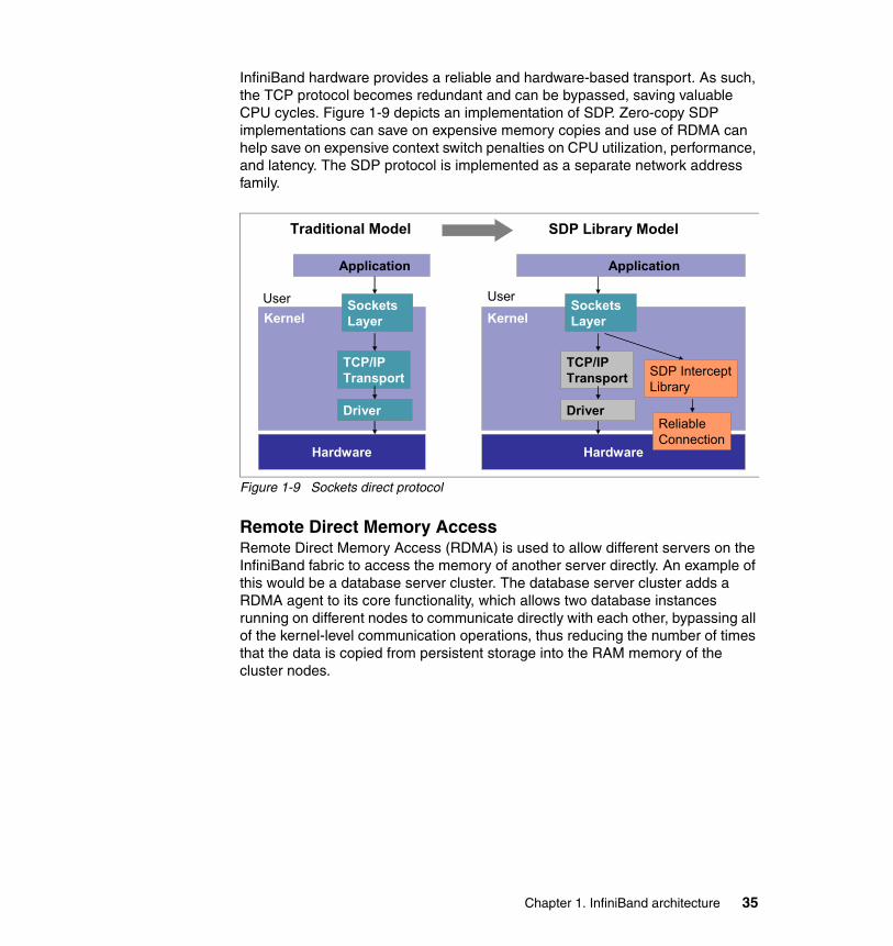
InfiniBand hardware provides a reliable and hardware-based transport. As such, the TCP protocol becomes redundant and can be bypassed, saving valuable CPU cycles. Figure 1-9 depicts an implementation of SDP. Zero-copy SDP implementations can save on expensive memory copies and use of RDMA can help save on expensive context switch penalties on CPU utilization, performance, and latency. The SDP protocol is implemented as a separate network address family.
Figure 1-9 Sockets direct protocol
Remote Direct Memory AccessRemote Direct Memory Access (RDMA) is used to allow different servers on the InfiniBand fabric to access the memory of another server directly. An example of this would be a database server cluster. The database server cluster adds a RDMA agent to its core functionality, which allows two database instances running on different nodes to communicate directly with each other, bypassing all of the kernel-level communication operations, thus reducing the number of times that the data is copied from persistent storage into the RAM memory of the cluster nodes.
Hardware
Application
KernelUser
TCP/IPTransport
Driver
Hardware
Application
KernelUser
TCP/IPTransport
DriverReliableConnection
SocketsLayer
SocketsLayer
SDP InterceptLibrary
Traditional Model SDP Library Model
Chapter 1. InfiniBand architecture 35
TCP does checksum in CPU and CRC in hardware. InfiniBand RDMA replaces checksums with improved CRCs. This is a tremendous improvement in the communication efficiency over TCP-based systems, as all of the TCP-generated kernel calls are skipped, and all of the CRC or checksum computations in the system CPU are passed to the HCA for both sending and receiving sides, as shown in Figure 1-10.
Figure 1-10 Remote Direct Memory Access
By off-loading the CRC or checksum operations to the HCA, the system CPU can deliver more productive work. RDMA implementations make servers more efficient to operate and allow the exploitation of ever-faster processor systems.
Because of the high-performance nature of InfiniBand, it allows for systems like database servers to deliver faster responses and more efficient operations.
Supporting SCSI and iSCSI protocol-based applicationsSCSI RDMA Protocol (SRP) was defined by the ANSI TiA committee to provide block storage capabilities for the InfiniBand architecture. SRP is a protocol that uses the InfiniBand Reliable Connection and RDMA capabilities to provide a high-performance transport for the SCSI protocol. SRP is extremely similar to FCP, which is used in Fibre Channel environments to provide SCSI over Fibre Channel. This allows one host driver to use storage target devices from various storage hardware vendors.
iSER (iSCSI RDMA) eliminates the traditional iSCSI and TCP bottlenecks by enabling zero-copy RDMA, offloading CRC calculations in the transport layer to the hardware, and by working with message boundaries instead of streams. It
Hardware
Application
Traditional Model Kernel Bypass Model
KernelUser
TCP/IPTransport
Driver
Hardware
Application
KernelUser
TCP/IPTransport
Driver
RDMA enabledULP application
SocketsLayer
SocketsLayer
36 HPC Clusters Using InfiniBand on IBM Power Systems Servers

leverages iSCSI management and discovery facilities and uses SLP and iSNS global storage naming.
Support for the Direct Access Programming Library (DAPL)The Direct Access Programming Library is a distributed messaging technology that is both hardware-independent and compatible with current network interconnects. The architecture provides an API that can be utilized to provide high-speed and low-latency communications among peers in clustered applications.
DAPL was an early effort to define an industry standard RDMA API. The DAPL API was heavily influenced by the InfiniBand architecture. DAPL has since been supplanted with the OFA-defined APIs. However, many InfiniBand implementations still support DAPL to enable continued use of older applications.
InfiniBand offloads traffic control from the software client through the use of execution queues. These queues, called work queues, are initiated by the client, then left for InfiniBand to manage. For each communication channel between devices, a work queue pair (WQP, send and receive queues) is assigned at each end. The client places a transaction into the work queue (work queue entry (WQE)), which is then processed by the channel adapter from the send queue and sent to the remote device. When the remote device responds, the channel adapter returns its status to the client through a completion queue or event.
The client can post multiple WQEs, and the channel adapter’s hardware handles each of the communication requests. The channel adapter then generates a completion queue entry (CQE) to provide the status for each WQE in the proper prioritized order. This enables the client to continue with other activities while the transactions are being processed.
Reliable datagram sockets (RDS)The RDS protocol uses InfiniBand delivery capabilities to offload end-to-end error checking to the InfiniBand fabric, which frees processor cycles for application processing and enables significant increases in processor scaling compared with Gigabit Ethernet implementations. The RDS protocol was designed by QLogic in collaboration with Oracle as a way to better optimize Oracle Database clustering and take advantage of InfiniBand capabilities.
Chapter 1. InfiniBand architecture 37
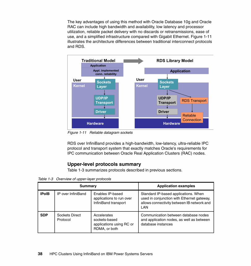
The key advantages of using this method with Oracle Database 10g and Oracle RAC can include high bandwidth and availability, low latency and processor utilization, reliable packet delivery with no discards or retransmissions, ease of use, and a simplified infrastructure compared with Gigabit Ethernet. Figure 1-11 illustrates the architecture differences between traditional interconnect protocols and RDS.
Figure 1-11 Reliable datagram sockets
RDS over InfiniBand provides a high-bandwidth, low-latency, ultra-reliable IPC protocol and transport system that exactly matches Oracle's requirements for IPC communication between Oracle Real Application Clusters (RAC) nodes.
Upper-level protocols summaryTable 1-3 summarizes protocols described in previous sections.
Table 1-3 Overview of upper-layer protocols
Hardware
Application
KernelUser
UDP/IPTransport
Driver
Hardware
Application
KernelUser
UDP/IPTransport
DriverReliableConnection
SocketsLayer
SocketsLayer
RDS Transport
Traditional Model RDS Library Model
Appl. implemented conn. reliability
Summary Application examples
IPoIB IP over InfiniBand Enables IP-based applications to run over InfiniBand transport
Standard IP-based applications. When used in conjunction with Ethernet gateway, allows connectivity between IB network and LAN
SDP Sockets Direct Protocol
Accelerates sockets-based applications using RC or RDMA, or both
Communication between database nodes and application nodes, as well as between database instances
38 HPC Clusters Using InfiniBand on IBM Power Systems Servers
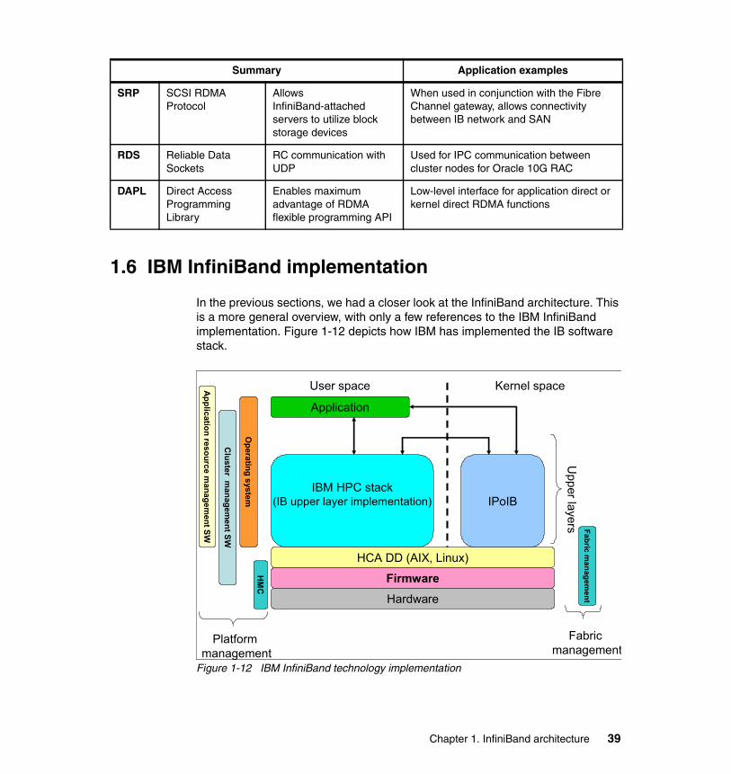
1.6 IBM InfiniBand implementation
In the previous sections, we had a closer look at the InfiniBand architecture. This is a more general overview, with only a few references to the IBM InfiniBand implementation. Figure 1-12 depicts how IBM has implemented the IB software stack.
Figure 1-12 IBM InfiniBand technology implementation
SRP SCSI RDMA Protocol
Allows InfiniBand-attached servers to utilize block storage devices
When used in conjunction with the Fibre Channel gateway, allows connectivity between IB network and SAN
RDS Reliable Data Sockets
RC communication with UDP
Used for IPC communication between cluster nodes for Oracle 10G RAC
DAPL Direct Access Programming Library
Enables maximum advantage of RDMA flexible programming API
Low-level interface for application direct or kernel direct RDMA functions
Summary Application examples
Application
IBM HPC stack(IB upper layer implementation)
HCA DD (AIX, Linux)
FirmwareHardware
IPoIB
Kernel spaceUser spaceApplication resource m
anagement SW
Upper layers
Cluster m
anagement SW
HM
CO
perating system
Fabric managem
ent
Platform management
Fabric management
Chapter 1. InfiniBand architecture 39
Although you will recognize some parts that we discussed before, Figure 1-12 on page 39 is meant to be used as an overview and introduction for the following sections of this publication, where each of these parts will be discussed in more detail.
1.7 Summary
InfiniBand offers advanced features that are attractive for high performance computing and data center applications that require high performance and no-compromise I/O services in the areas of throughput, latency, and end-to-end service-level guarantees. Using the protocols previously discussed, applications that run today over lower performing interconnects can be transparently migrated, without any changes, to work over InfiniBand and exploit the advanced features.
40 HPC Clusters Using InfiniBand on IBM Power Systems Servers
Chapter 2. High performance computing hardware components using InfiniBand
This chapter provides technical information about hardware components in an high performance computing (HPC) environment using InfiniBand on IBM POWER6 Systems. This chapter discusses the following topics:
� POWER6 Systems � Host channel adapter� HCA and LPARs� InfiniBand cables� InfiniBand switches� Cluster management server
2
© Copyright IBM Corp. 2009. All rights reserved. 41
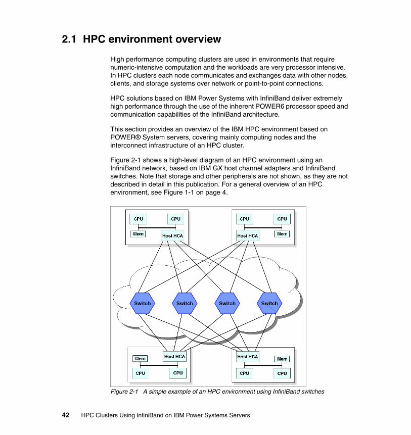
2.1 HPC environment overview
High performance computing clusters are used in environments that require numeric-intensive computation and the workloads are very processor intensive. In HPC clusters each node communicates and exchanges data with other nodes, clients, and storage systems over network or point-to-point connections.
HPC solutions based on IBM Power Systems with InfiniBand deliver extremely high performance through the use of the inherent POWER6 processor speed and communication capabilities of the InfiniBand architecture.
This section provides an overview of the IBM HPC environment based on POWER® System servers, covering mainly computing nodes and the interconnect infrastructure of an HPC cluster.
Figure 2-1 shows a high-level diagram of an HPC environment using an InfiniBand network, based on IBM GX host channel adapters and InfiniBand switches. Note that storage and other peripherals are not shown, as they are not described in detail in this publication. For a general overview of an HPC environment, see Figure 1-1 on page 4.
Figure 2-1 A simple example of an HPC environment using InfiniBand switches
42 HPC Clusters Using InfiniBand on IBM Power Systems Servers
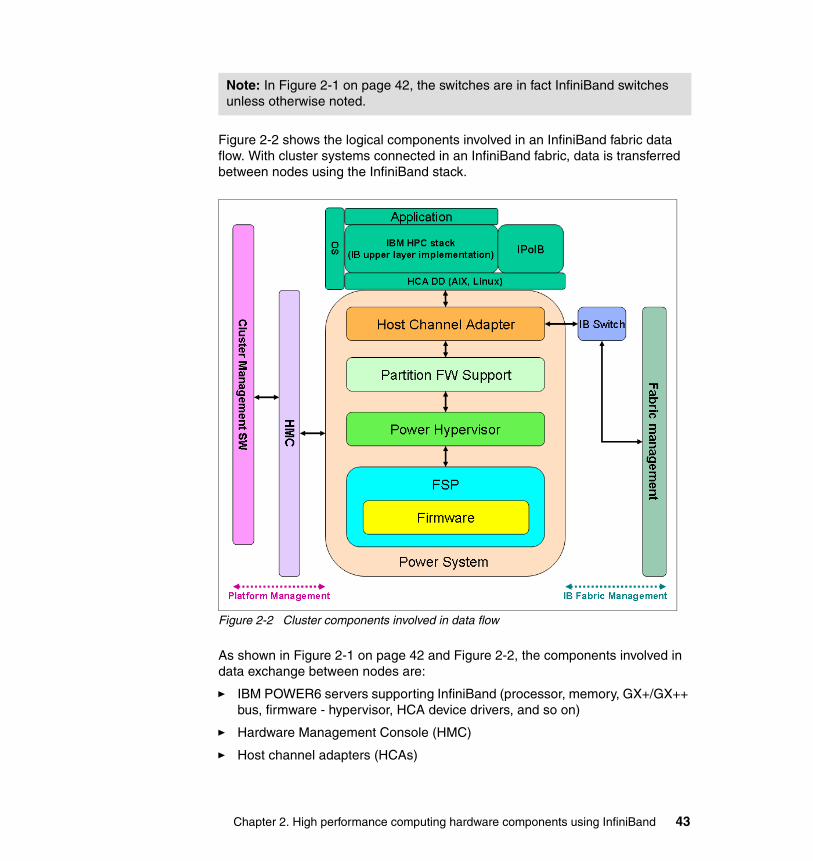
Figure 2-2 shows the logical components involved in an InfiniBand fabric data flow. With cluster systems connected in an InfiniBand fabric, data is transferred between nodes using the InfiniBand stack.
Figure 2-2 Cluster components involved in data flow
As shown in Figure 2-1 on page 42 and Figure 2-2, the components involved in data exchange between nodes are:
� IBM POWER6 servers supporting InfiniBand (processor, memory, GX+/GX++ bus, firmware - hypervisor, HCA device drivers, and so on)
� Hardware Management Console (HMC)
� Host channel adapters (HCAs)
Note: In Figure 2-1 on page 42, the switches are in fact InfiniBand switches unless otherwise noted.
Chapter 2. High performance computing hardware components using InfiniBand 43
� InfiniBand switches and management software
� InfiniBand cables
� Cluster management software
In the following sections, we provide technical descriptions for each hardware component involved in an HPC environment using InfiniBand on POWER6 servers.
2.2 POWER6 Systems
POWER6 Systems combine industry-leading performance, scalability and modularity to enable you to get the most from your investment and build a flexible, dynamic infrastructure that easily adapts and grows based on your business needs.
Currently, POWER6 Systems provide the best on the market performance per processor core and scalability with the following main features:
� Ultra-high frequency, dual-core processor technology with leading performance across the most-published server benchmarks representing the broadest range of application performance.
� Mainframe-inspired reliability with instruction retry on alternate processors and storage keys to deliver higher availability and protect data from corruption.
� EnergyScale™ technology to reduce energy consumption and provide the ability to manage and customize energy usage.
� Live Partition Mobility and Live Application Mobility to sustain system availability during maintenance or re-hosting.
� Concurrent firmware and operating system updates to enable applications to remain continuously available.
44 HPC Clusters Using InfiniBand on IBM Power Systems Servers
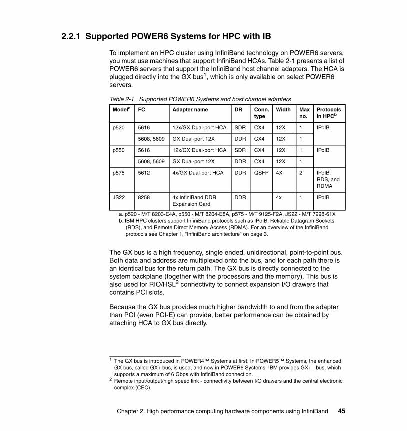
2.2.1 Supported POWER6 Systems for HPC with IB
To implement an HPC cluster using InfiniBand technology on POWER6 servers, you must use machines that support InfiniBand HCAs. Table 2-1 presents a list of POWER6 servers that support the InfiniBand host channel adapters. The HCA is plugged directly into the GX bus1, which is only available on select POWER6 servers.
Table 2-1 Supported POWER6 Systems and host channel adapters
The GX bus is a high frequency, single ended, unidirectional, point-to-point bus. Both data and address are multiplexed onto the bus, and for each path there is an identical bus for the return path. The GX bus is directly connected to the system backplane (together with the processors and the memory). This bus is also used for RIO/HSL2 connectivity to connect expansion I/O drawers that contains PCI slots.
Because the GX bus provides much higher bandwidth to and from the adapter than PCI (even PCI-E) can provide, better performance can be obtained by attaching HCA to GX bus directly.
1 The GX bus is introduced in POWER4™ Systems at first. In POWER5™ Systems, the enhanced GX bus, called GX+ bus, is used, and now in POWER6 Systems, IBM provides GX++ bus, which supports a maximum of 6 Gbps with InfiniBand connection.
Modela
a. p520 - M/T 8203-E4A, p550 - M/T 8204-E8A, p575 - M/T 9125-F2A, JS22 - M/T 7998-61X
FC Adapter name DR Conn. type
Width Max no.
Protocols in HPCb
b. IBM HPC clusters support InfiniBand protocols such as IPoIB, Reliable Datagram Sockets (RDS), and Remote Direct Memory Access (RDMA). For an overview of the InfiniBand protocols see Chapter 1, “InfiniBand architecture” on page 3.
p520 5616 12x/GX Dual-port HCA SDR CX4 12X 1 IPoIB
5608, 5609 GX Dual-port 12X DDR CX4 12X 1
p550 5616 12x/GX Dual-port HCA SDR CX4 12X 1 IPoIB
5608, 5609 GX Dual-port 12X DDR CX4 12X 1
p575 5612 4x/GX Dual-port HCA DDR QSFP 4X 2 IPoIB, RDS, and RDMA
JS22 8258 4x InfiniBand DDR Expansion Card
DDR 4x 1 IPoIB
2 Remote input/output/high speed link - connectivity between I/O drawers and the central electronic complex (CEC).
Chapter 2. High performance computing hardware components using InfiniBand 45
For the latest information about supported HCAs on POWER6 Systems, check the “Planning for QLogic InfiniBand switches in System Hardware Information Center” Web page at:
http://publib.boulder.ibm.com/infocenter/systems/scope/hw/index.jsp
Currently, IBM supports two types of cluster environments using InfiniBand:
� HPC � Commercial3
As shown in Table 2-1 on page 45, the IBM POWER6 servers models 8203-E4A (p520), 8204-E8A (p550), and 9125-F2A (p575) are supported for an HPC environment. The IBM Power System server 9125-F2A supports a full HPC environment through IPoIB and user space applications. In HPC clusters, POWER6 servers 8203-E3A and 8204-E8A are generally used as storage nodes for GPFS and are only qualified for IPoIB. The 7998-61X (IBM BladeCenter® JS22) only supports IPoIB in HPC configurations.
Note: In general, RIO/HSL and 12x HCA are installed in GX adapter slots, so they are collectively referred as GX adapters.
3 The commercial clusters support Oracle RAC by scaling up to 16 servers and 1 or 2 InfiniBand subnets. HPC clusters support many more nodes and different software stack such as Message Passing Interface (MPI).
46 HPC Clusters Using InfiniBand on IBM Power Systems Servers
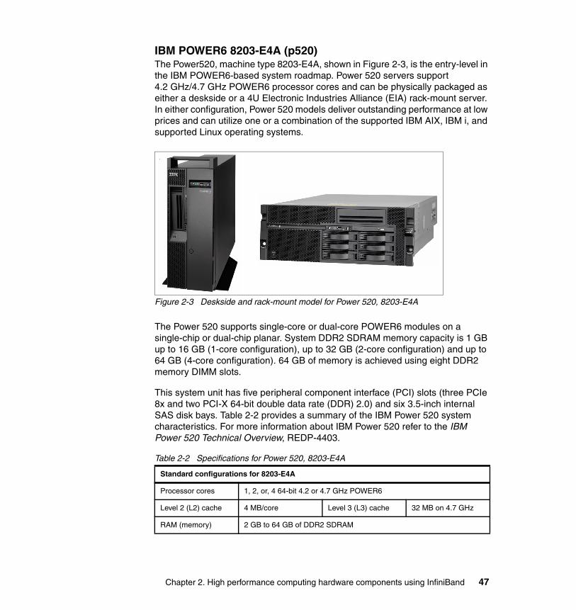
IBM POWER6 8203-E4A (p520)The Power520, machine type 8203-E4A, shown in Figure 2-3, is the entry-level in the IBM POWER6-based system roadmap. Power 520 servers support 4.2 GHz/4.7 GHz POWER6 processor cores and can be physically packaged as either a deskside or a 4U Electronic Industries Alliance (EIA) rack-mount server. In either configuration, Power 520 models deliver outstanding performance at low prices and can utilize one or a combination of the supported IBM AIX, IBM i, and supported Linux operating systems.
Figure 2-3 Deskside and rack-mount model for Power 520, 8203-E4A
The Power 520 supports single-core or dual-core POWER6 modules on a single-chip or dual-chip planar. System DDR2 SDRAM memory capacity is 1 GB up to 16 GB (1-core configuration), up to 32 GB (2-core configuration) and up to 64 GB (4-core configuration). 64 GB of memory is achieved using eight DDR2 memory DIMM slots.
This system unit has five peripheral component interface (PCI) slots (three PCIe 8x and two PCI-X 64-bit double data rate (DDR) 2.0) and six 3.5-inch internal SAS disk bays. Table 2-2 provides a summary of the IBM Power 520 system characteristics. For more information about IBM Power 520 refer to the IBM Power 520 Technical Overview, REDP-4403.
Table 2-2 Specifications for Power 520, 8203-E4A
Standard configurations for 8203-E4A
Processor cores 1, 2, or, 4 64-bit 4.2 or 4.7 GHz POWER6
Level 2 (L2) cache 4 MB/core Level 3 (L3) cache 32 MB on 4.7 GHz
RAM (memory) 2 GB to 64 GB of DDR2 SDRAM
Chapter 2. High performance computing hardware components using InfiniBand 47
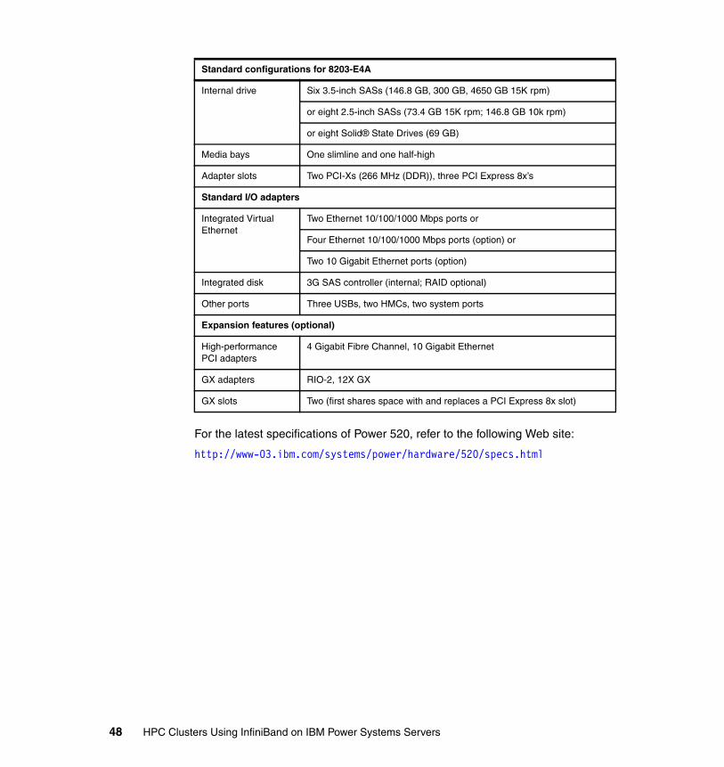
For the latest specifications of Power 520, refer to the following Web site:
http://www-03.ibm.com/systems/power/hardware/520/specs.html
Internal drive Six 3.5-inch SASs (146.8 GB, 300 GB, 4650 GB 15K rpm)
or eight 2.5-inch SASs (73.4 GB 15K rpm; 146.8 GB 10k rpm)
or eight Solid® State Drives (69 GB)
Media bays One slimline and one half-high
Adapter slots Two PCI-Xs (266 MHz (DDR)), three PCI Express 8x’s
Standard I/O adapters
Integrated Virtual Ethernet
Two Ethernet 10/100/1000 Mbps ports or
Four Ethernet 10/100/1000 Mbps ports (option) or
Two 10 Gigabit Ethernet ports (option)
Integrated disk 3G SAS controller (internal; RAID optional)
Other ports Three USBs, two HMCs, two system ports
Expansion features (optional)
High-performance PCI adapters
4 Gigabit Fibre Channel, 10 Gigabit Ethernet
GX adapters RIO-2, 12X GX
GX slots Two (first shares space with and replaces a PCI Express 8x slot)
Standard configurations for 8203-E4A
48 HPC Clusters Using InfiniBand on IBM Power Systems Servers
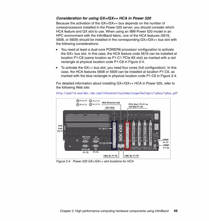
Consideration for using GX+/GX++ HCA in Power 520Because the activation of the GX+/GX++ bus depends on the number of cores/processors installed in the Power 520 server, you should consider which HCA feature and GX slot to use. When using an IBM Power 520 model in an HPC environment with the InfiniBand fabric, one of the HCA features (5616, 5608, or 5609) should be installed in the corresponding GX+/GX++ bus slot with the following considerations:
� You need at least a dual-core POWER6 processor configuration to activate the GX+ bus slot. In this case, the HCA feature code 5616 can be installed at location P1-C8 (same location as P1-C1 PCIe 8X slot) as marked with a red rectangle at physical location code P1-C8 in Figure 2-4.
� To activate the GX++ bus slot, you need four cores (full configuration). In this case, the HCA features 5608 or 5609 can be installed at location P1-C6, as marked with the blue rectangle in physical location code P1-C6 in Figure 2-4.
For detailed information about installing GX+/GX++ HCA in Power 520, refer to the following Web site:
http://publib.boulder.ibm.com/infocenter/systems/scope/hw/topic/iphas/iphas.pdf
Figure 2-4 Power 520 GX+/GX++ slot locations for HCA
Chapter 2. High performance computing hardware components using InfiniBand 49
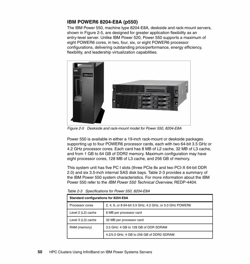
IBM POWER6 8204-E8A (p550)The IBM Power 550, machine type 8204-E8A, deskside and rack-mount servers, shown in Figure 2-5, are designed for greater application flexibility as an entry-level server. Unlike IBM Power 520, Power 550 supports a maximum of eight POWER6 cores, in two, four, six, or eight POWER6 processor configurations, delivering outstanding price/performance, energy efficiency, flexibility, and leadership virtualization capabilities.
Figure 2-5 Deskside and rack-mount model for Power 550, 8204-E8A
Power 550 is available in either a 19-inch rack-mount or deskside packages supporting up to four POWER6 processor cards, each with two 64-bit 3.5 GHz or 4.2 GHz processor cores. Each card has 8 MB of L2 cache, 32 MB of L3 cache, and from 1 GB to 64 GB of DDR2 memory. Maximum configuration may have eight processor cores, 128 MB of L3 cache, and 256 GB of memory.
This system unit has five PC I slots (three PCIe 8x and two PCI-X 64-bit DDR 2.0) and six 3.5-inch internal SAS disk bays. Table 2-3 provides a summary of the IBM Power 550 system characteristics. For more information about the IBM Power 550 refer to the IBM Power 550 Technical Overview, REDP-4404.
Table 2-3 Specifications for Power 550, 8204-E8A
Standard configurations for 8204-E8A
Processor cores 2, 4, 6, or 8 64-bit 3.5 GHz, 4.2 GHz, or 5.0 GHz POWER6
Level 2 (L2) cache 8 MB per processor card
Level 3 (L3) cache 32 MB per processor card
RAM (memory) 3.5 GHz: 4 GB to 128 GB of DDR SDRAM
4.2/5.0 GHz: 4 GB to 256 GB of DDR2 SDRAM
50 HPC Clusters Using InfiniBand on IBM Power Systems Servers
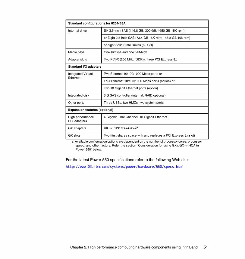
For the latest Power 550 specifications refer to the following Web site:
http://www-03.ibm.com/systems/power/hardware/550/specs.html
Internal drive Six 3.5-inch SAS (146.8 GB, 300 GB, 4650 GB 15K rpm)
or Eight 2.5-inch SAS (73.4 GB 15K rpm; 146.8 GB 10k rpm)
or eight Solid State Drives (69 GB)
Media bays One slimline and one half-high
Adapter slots Two PCI-X (266 MHz (DDR)), three PCI Express 8x
Standard I/O adapters
Integrated Virtual Ethernet
Two Ethernet 10/100/1000 Mbps ports or
Four Ethernet 10/100/1000 Mbps ports (option) or
Two 10 Gigabit Ethernet ports (option)
Integrated disk 3 G SAS controller (internal; RAID optional)
Other ports Three USBs, two HMCs, two system ports
Expansion features (optional)
High-performance PCI adapters
4 Gigabit Fibre Channel, 10 Gigabit Ethernet
GX adapters RIO-2, 12X GX+/GX++a
GX slots Two (first shares space with and replaces a PCI Express 8x slot)
a. Available configuration options are dependent on the number of processor cores, processor speed, and other factors. Refer the section “Consideration for using GX+/GX++ HCA in Power 550” below.
Standard configurations for 8204-E8A
Chapter 2. High performance computing hardware components using InfiniBand 51
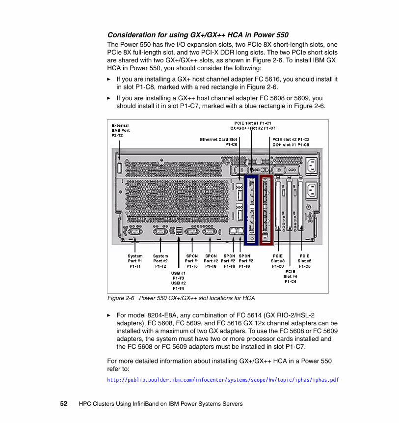
Consideration for using GX+/GX++ HCA in Power 550The Power 550 has five I/O expansion slots, two PCIe 8X short-length slots, one PCIe 8X full-length slot, and two PCI-X DDR long slots. The two PCIe short slots are shared with two GX+/GX++ slots, as shown in Figure 2-6. To install IBM GX HCA in Power 550, you should consider the following:
� If you are installing a GX+ host channel adapter FC 5616, you should install it in slot P1-C8, marked with a red rectangle in Figure 2-6.
� If you are installing a GX++ host channel adapter FC 5608 or 5609, you should install it in slot P1-C7, marked with a blue rectangle in Figure 2-6.
Figure 2-6 Power 550 GX+/GX++ slot locations for HCA
� For model 8204-E8A, any combination of FC 5614 (GX RIO-2/HSL-2 adapters), FC 5608, FC 5609, and FC 5616 GX 12x channel adapters can be installed with a maximum of two GX adapters. To use the FC 5608 or FC 5609 adapters, the system must have two or more processor cards installed and the FC 5608 or FC 5609 adapters must be installed in slot P1-C7.
For more detailed information about installing GX+/GX++ HCA in a Power 550 refer to:
http://publib.boulder.ibm.com/infocenter/systems/scope/hw/topic/iphas/iphas.pdf
52 HPC Clusters Using InfiniBand on IBM Power Systems Servers

IBM POWER6 9125-F2A (p575)The IBM POWER6 9125-F2A, Power 575, is the node optimized for running large, highly parallel computationally intensive workload and algorithms. It is designed for organizations that require highly scalable supercomputers with extreme parallel processing performance and dense, modular packaging.
Ideal workloads for this system include high performance computing applications such as weather and climate modeling, computational chemistry, physics, computer-aided engineering, and computational fluid dynamics and petroleum exploration that require highly intense computations where the workload is aligned with parallel processing methodologies.
9125-F2A system configurationThe IBM Power 575 system is characterized by innovative, elegant conceptual design and packaging. Mounted in a sleek 2U enclosure, the modular Power 575 allows users to deploy up to 14 water-cooled nodes in a single, 24-inch system frame. To increase the rack density of the Power 575 supercomputing node, the microprocessors are cooled with an innovative modular water cooling system.
Chapter 2. High performance computing hardware components using InfiniBand 53
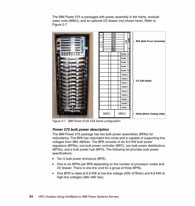
The IBM Power 575 is packaged with power assembly in the frame, modular water units (MWU), and an optional I/O drawer (not shown here). Refer to Figure 2-7.
Figure 2-7 IBM Power 9125-F2A frame configuration
Power 575 bulk power descriptionThe IBM Power 575 package has two bulk power assemblies (BPAs) for redundancy. The BPA has redundant line cords and is capable of supporting line voltages from 380–480Vac. The BPA consists of six 8.0 KW bulk power regulators (BPRs), one bulk power controller (BPC), two bulk power distributions (BPDs), and a bulk power hub (BPH). The following list provides bulk power specifications:
� Ten U bulk power enclosure (BPE).
� One to six BPRs per BPA depending on the number of processor nodes and I/O drawer. There is one line cord for a group of three BPRs.
� One BPR is rated at 8.0 KW at low-line voltage (200–278Vac) and 8.8 KW at high-line voltages (380–480 Vac).
54 HPC Clusters Using InfiniBand on IBM Power Systems Servers
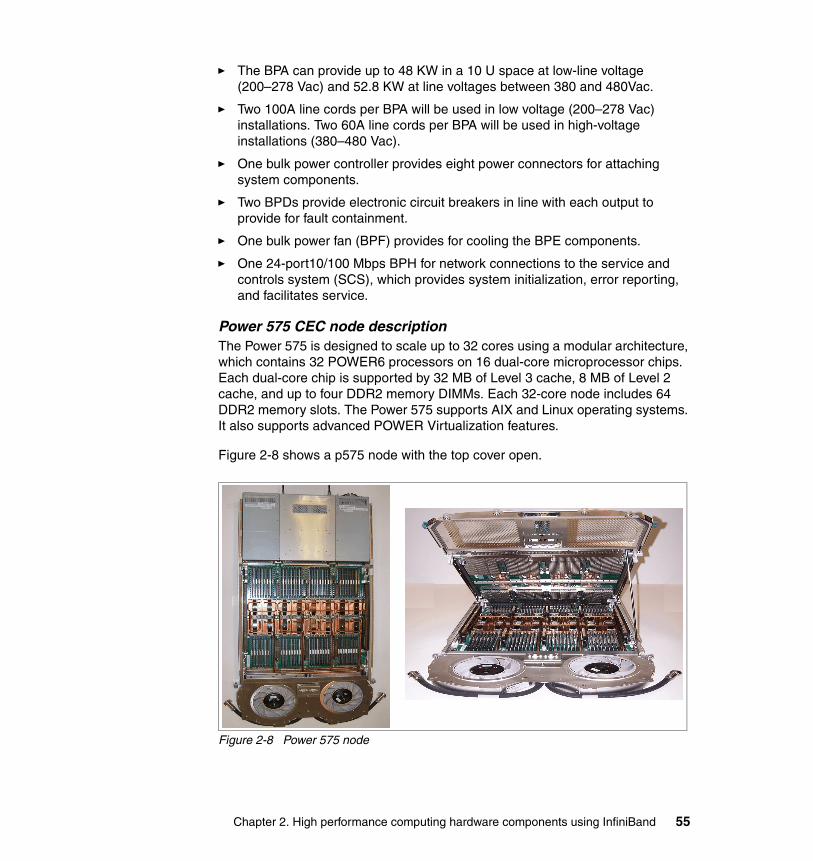
� The BPA can provide up to 48 KW in a 10 U space at low-line voltage (200–278 Vac) and 52.8 KW at line voltages between 380 and 480Vac.
� Two 100A line cords per BPA will be used in low voltage (200–278 Vac) installations. Two 60A line cords per BPA will be used in high-voltage installations (380–480 Vac).
� One bulk power controller provides eight power connectors for attaching system components.
� Two BPDs provide electronic circuit breakers in line with each output to provide for fault containment.
� One bulk power fan (BPF) provides for cooling the BPE components.
� One 24-port10/100 Mbps BPH for network connections to the service and controls system (SCS), which provides system initialization, error reporting, and facilitates service.
Power 575 CEC node descriptionThe Power 575 is designed to scale up to 32 cores using a modular architecture, which contains 32 POWER6 processors on 16 dual-core microprocessor chips. Each dual-core chip is supported by 32 MB of Level 3 cache, 8 MB of Level 2 cache, and up to four DDR2 memory DIMMs. Each 32-core node includes 64 DDR2 memory slots. The Power 575 supports AIX and Linux operating systems. It also supports advanced POWER Virtualization features.
Figure 2-8 shows a p575 node with the top cover open.
Figure 2-8 Power 575 node
Chapter 2. High performance computing hardware components using InfiniBand 55
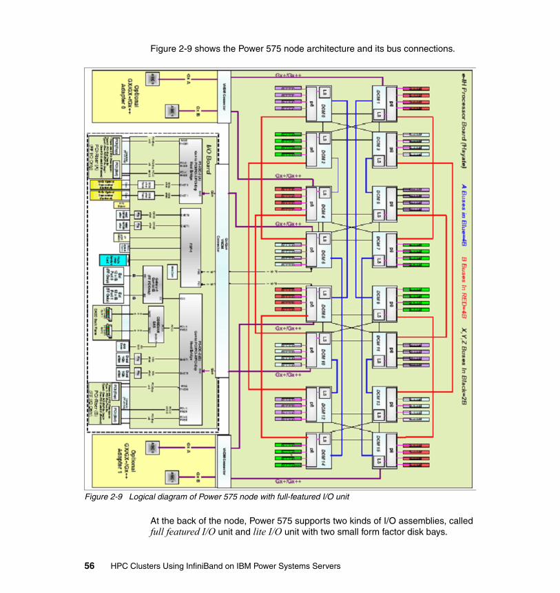
Figure 2-9 shows the Power 575 node architecture and its bus connections.
Figure 2-9 Logical diagram of Power 575 node with full-featured I/O unit
At the back of the node, Power 575 supports two kinds of I/O assemblies, called full featured I/O unit and lite I/O unit with two small form factor disk bays.
56 HPC Clusters Using InfiniBand on IBM Power Systems Servers
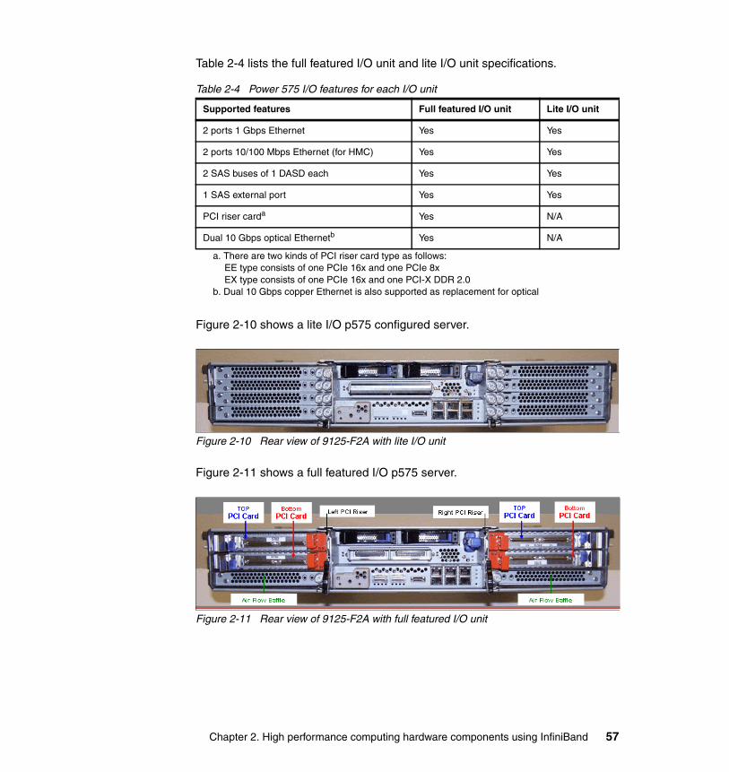
Table 2-4 lists the full featured I/O unit and lite I/O unit specifications.
Table 2-4 Power 575 I/O features for each I/O unit
Figure 2-10 shows a lite I/O p575 configured server.
Figure 2-10 Rear view of 9125-F2A with lite I/O unit
Figure 2-11 shows a full featured I/O p575 server.
Figure 2-11 Rear view of 9125-F2A with full featured I/O unit
Supported features Full featured I/O unit Lite I/O unit
2 ports 1 Gbps Ethernet Yes Yes
2 ports 10/100 Mbps Ethernet (for HMC) Yes Yes
2 SAS buses of 1 DASD each Yes Yes
1 SAS external port Yes Yes
PCI riser carda
a. There are two kinds of PCI riser card type as follows:EE type consists of one PCIe 16x and one PCIe 8xEX type consists of one PCIe 16x and one PCI-X DDR 2.0
Yes N/A
Dual 10 Gbps optical Ethernetb
b. Dual 10 Gbps copper Ethernet is also supported as replacement for optical
Yes N/A
Chapter 2. High performance computing hardware components using InfiniBand 57
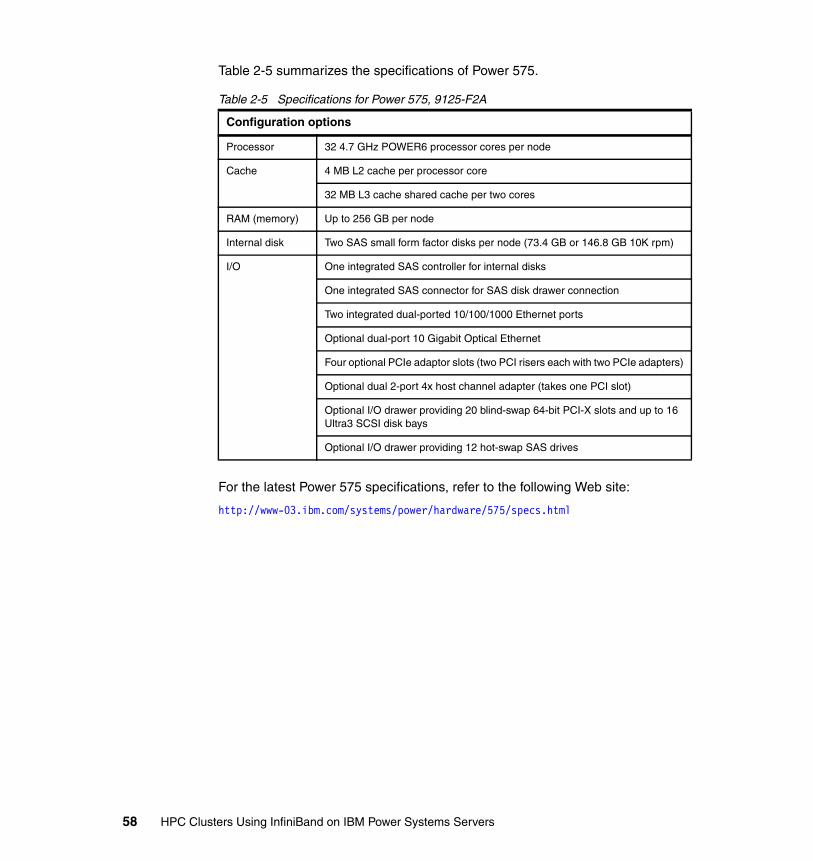
Table 2-5 summarizes the specifications of Power 575.
Table 2-5 Specifications for Power 575, 9125-F2A
For the latest Power 575 specifications, refer to the following Web site:
http://www-03.ibm.com/systems/power/hardware/575/specs.html
Configuration options
Processor 32 4.7 GHz POWER6 processor cores per node
Cache 4 MB L2 cache per processor core
32 MB L3 cache shared cache per two cores
RAM (memory) Up to 256 GB per node
Internal disk Two SAS small form factor disks per node (73.4 GB or 146.8 GB 10K rpm)
I/O One integrated SAS controller for internal disks
One integrated SAS connector for SAS disk drawer connection
Two integrated dual-ported 10/100/1000 Ethernet ports
Optional dual-port 10 Gigabit Optical Ethernet
Four optional PCIe adaptor slots (two PCI risers each with two PCIe adapters)
Optional dual 2-port 4x host channel adapter (takes one PCI slot)
Optional I/O drawer providing 20 blind-swap 64-bit PCI-X slots and up to 16 Ultra3 SCSI disk bays
Optional I/O drawer providing 12 hot-swap SAS drives
58 HPC Clusters Using InfiniBand on IBM Power Systems Servers
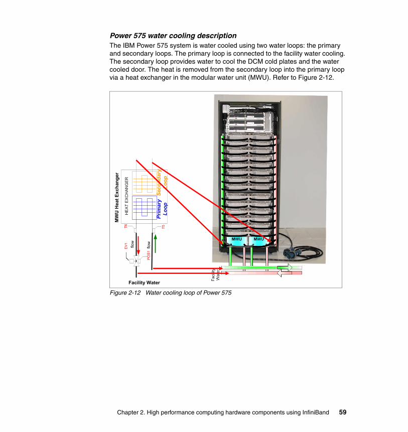
Power 575 water cooling descriptionThe IBM Power 575 system is water cooled using two water loops: the primary and secondary loops. The primary loop is connected to the facility water cooling. The secondary loop provides water to cool the DCM cold plates and the water cooled door. The heat is removed from the secondary loop into the primary loop via a heat exchanger in the modular water unit (MWU). Refer to Figure 2-12.
Figure 2-12 Water cooling loop of Power 575
Facility Water
MW
U H
eat E
xcha
nger
Chapter 2. High performance computing hardware components using InfiniBand 59
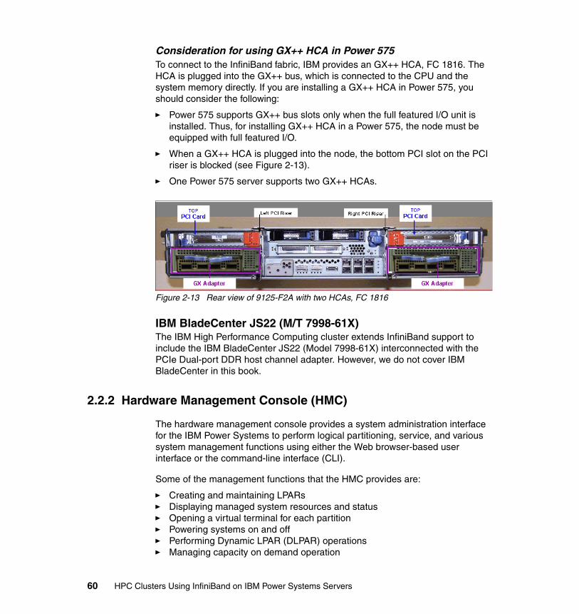
Consideration for using GX++ HCA in Power 575To connect to the InfiniBand fabric, IBM provides an GX++ HCA, FC 1816. The HCA is plugged into the GX++ bus, which is connected to the CPU and the system memory directly. If you are installing a GX++ HCA in Power 575, you should consider the following:
� Power 575 supports GX++ bus slots only when the full featured I/O unit is installed. Thus, for installing GX++ HCA in a Power 575, the node must be equipped with full featured I/O.
� When a GX++ HCA is plugged into the node, the bottom PCI slot on the PCI riser is blocked (see Figure 2-13).
� One Power 575 server supports two GX++ HCAs.
Figure 2-13 Rear view of 9125-F2A with two HCAs, FC 1816
IBM BladeCenter JS22 (M/T 7998-61X)The IBM High Performance Computing cluster extends InfiniBand support to include the IBM BladeCenter JS22 (Model 7998-61X) interconnected with the PCIe Dual-port DDR host channel adapter. However, we do not cover IBM BladeCenter in this book.
2.2.2 Hardware Management Console (HMC)
The hardware management console provides a system administration interface for the IBM Power Systems to perform logical partitioning, service, and various system management functions using either the Web browser-based user interface or the command-line interface (CLI).
Some of the management functions that the HMC provides are:
� Creating and maintaining LPARs� Displaying managed system resources and status� Opening a virtual terminal for each partition� Powering systems on and off� Performing Dynamic LPAR (DLPAR) operations� Managing capacity on demand operation
60 HPC Clusters Using InfiniBand on IBM Power Systems Servers
� Managing virtualization features� Managing platform firmware installation and upgrade� Acting as a service focal point
For the detailed HMC functionality information, refer to Hardware Management Console V7 Handbook, SG24-7491.
Supported HMC type and modelFor IBM POWER6 Systems, the following HMC options are available when ordering new systems:
� 7042-C06 (desktop)� 7042-CR4 (rack mounted)
However, all (older) 7310 models are also supported. Thus, if you have these HMC types available, you can use them to manage HPC nodes with IB, provided that they are at the supported HMC level, as listed at:
http://www14.software.ibm.com/webapp/set2/sas/f/networkmanager/power6/codelevels.html
2.2.3 POWER Systems firmware
Firmware or microcode is specialized code programmed into the hardware components to control their operation. Microcode generally initializes the hardware, enabling it to boot up and operate. In many cases it may also provide some of the interface between the hardware and device-drivers or the operating system.
Microcode is usually found programmed into modules on cards, adapters, or devices. If these modules are flash memory, you can update the code rather than having to change the card or device.
System microcode initializes the system hardware and controls the boot process, enabling the system to boot up and operate correctly. It also provides the interface between the operating system software and the hardware.
Adapter Microcode is the operating code of the adapter. It initializes the adapter when power is applied and it controls many of the ongoing operations executed by the adapter.
Device microcode provides these same functions for devices such as tape drives.
Chapter 2. High performance computing hardware components using InfiniBand 61
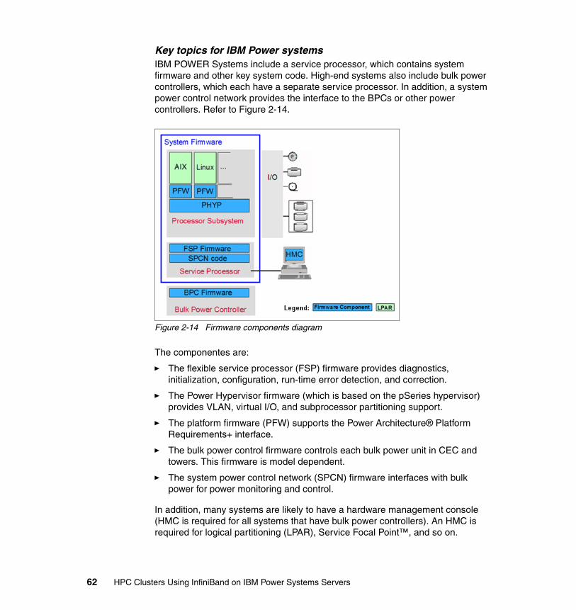
Key topics for IBM Power systemsIBM POWER Systems include a service processor, which contains system firmware and other key system code. High-end systems also include bulk power controllers, which each have a separate service processor. In addition, a system power control network provides the interface to the BPCs or other power controllers. Refer to Figure 2-14.
Figure 2-14 Firmware components diagram
The componentes are:
� The flexible service processor (FSP) firmware provides diagnostics, initialization, configuration, run-time error detection, and correction.
� The Power Hypervisor firmware (which is based on the pSeries hypervisor) provides VLAN, virtual I/O, and subprocessor partitioning support.
� The platform firmware (PFW) supports the Power Architecture® Platform Requirements+ interface.
� The bulk power control firmware controls each bulk power unit in CEC and towers. This firmware is model dependent.
� The system power control network (SPCN) firmware interfaces with bulk power for power monitoring and control.
In addition, many systems are likely to have a hardware management console (HMC is required for all systems that have bulk power controllers). An HMC is required for logical partitioning (LPAR), Service Focal Point™, and so on.
62 HPC Clusters Using InfiniBand on IBM Power Systems Servers
Firmware requirements of POWER6 SystemsPOWER6 Systems that support an HPC environment with InfiniBand need a minimum level of system firmware installed to be fully functional. In this section, we document the recommended firmware level for POWER6 servers supported in an HPC environment. For the latest firmware, refer to the following Web site:
http://www14.software.ibm.com/webapp/set2/sas/f/networkmanager/power6/codelevels.html
For Power 575At the date of this writing, the mandatory prerequisite firmware levels of Power 575 are:
� Global firmware: fix pack 01ES340_061� Power subsystem firmware: 02EP340_052
The recommended firmware levels are:
� Global firmware: fix pack 01ES340_061� Power subsystem firmware: 02EP340_052
Currently, these are also the minimum requirements.
To install the power code and system firmware, follow the instructions at the following Web site:
http://www14.software.ibm.com/webapp/set2/firmware/gjsn?mode=1&mtm=9125-F2A
For Power 520 and 550At present, the mandatory prerequisites and recommended firmware levels for Power 520 and 550 are:
� Mandatory prerequisite: fix pack EL320_083� Recommended firmware level: fix pack 01EL340_061
Chapter 2. High performance computing hardware components using InfiniBand 63
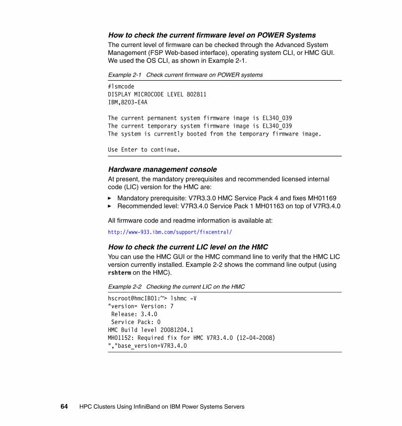
How to check the current firmware level on POWER SystemsThe current level of firmware can be checked through the Advanced System Management (FSP Web-based interface), operating system CLI, or HMC GUI. We used the OS CLI, as shown in Example 2-1.
Example 2-1 Check current firmware on POWER systems
#lsmcodeDISPLAY MICROCODE LEVEL 802811IBM,8203-E4A
The current permanent system firmware image is EL340_039The current temporary system firmware image is EL340_039The system is currently booted from the temporary firmware image.
Use Enter to continue.
Hardware management console At present, the mandatory prerequisites and recommended licensed internal code (LIC) version for the HMC are:
� Mandatory prerequisite: V7R3.3.0 HMC Service Pack 4 and fixes MH01169� Recommended level: V7R3.4.0 Service Pack 1 MH01163 on top of V7R3.4.0
All firmware code and readme information is available at:
http://www-933.ibm.com/support/fixcentral/
How to check the current LIC level on the HMCYou can use the HMC GUI or the HMC command line to verify that the HMC LIC version currently installed. Example 2-2 shows the command line output (using rshterm on the HMC).
Example 2-2 Checking the current LIC on the HMC
hscroot@hmcIB01:~> lshmc -V"version= Version: 7 Release: 3.4.0 Service Pack: 0HMC Build level 20081204.1MH01152: Required fix for HMC V7R3.4.0 (12-04-2008)","base_version=V7R3.4.0
64 HPC Clusters Using InfiniBand on IBM Power Systems Servers
2.2.4 Power Hypervisor
The POWER Hypervisor™ is an essential element of the IBM Virtualization Engine system technologies implemented in the POWER6 processor-based family of products. Combined with features designed into the POWER6 processor, the POWER Hypervisor delivers functions that enable other system technologies, including logical partitioning, virtualized processors, IEEE VLAN compatible virtual switch, virtual SCSI adapters, and shared and virtual consoles.
OverviewThe POWER6 Hypervisor is a type 1 hypervisor integrated with all IBM System p6 models as part of the system firmware. The hypervisor enables system virtualization, including creating logical partitions and dynamically moving resources across multiple operating environments.
The POWER6 Hypervisor provides the ability to divide physical system resources into isolated logical partitions. Each logical partition operates like an independent system running its own operating environment: AIX, Linux, or the Virtual I/O Server. The hypervisor can assign dedicated processors, I/O, and memory (which you can dynamically reconfigure as needed) to each logical partition. With its Micro-Partitioning™ feature activated, the hypervisor can also assign shared processors to each logical partition. Unknown to the logical partitions, the hypervisor creates a shared processor pool from which it allocates virtual processors to the logical partitions as needed. In other words, the hypervisor creates virtual processors so that logical partitions can share the physical processors while running independent operating environments.
As a key component of the functions, the POWER Hypervisor performs the following tasks:
� It provides an abstraction layer between the physical hardware resources and the logical partitions using them.
� It enforces partition integrity by providing a security layer between logical partitions.
� It controls the dispatch of virtual processors to physical processors.
� It saves and restores all processor state information during logical processor context switch.
� It controls hardware I/O interrupt management facilities for logical partitions.
Chapter 2. High performance computing hardware components using InfiniBand 65
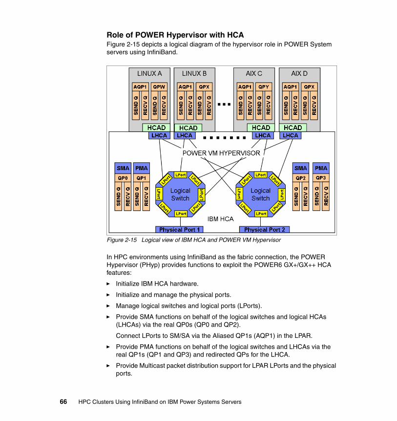
Role of POWER Hypervisor with HCAFigure 2-15 depicts a logical diagram of the hypervisor role in POWER System servers using InfiniBand.
Figure 2-15 Logical view of IBM HCA and POWER VM Hypervisor
In HPC environments using InfiniBand as the fabric connection, the POWER Hypervisor (PHyp) provides functions to exploit the POWER6 GX+/GX++ HCA features:
� Initialize IBM HCA hardware.
� Initialize and manage the physical ports.
� Manage logical switches and logical ports (LPorts).
� Provide SMA functions on behalf of the logical switches and logical HCAs (LHCAs) via the real QP0s (QP0 and QP2).
Connect LPorts to SM/SA via the Aliased QP1s (AQP1) in the LPAR.
� Provide PMA functions on behalf of the logical switches and LHCAs via the real QP1s (QP1 and QP3) and redirected QPs for the LHCA.
� Provide Multicast packet distribution support for LPAR LPorts and the physical ports.
66 HPC Clusters Using InfiniBand on IBM Power Systems Servers
� Manage the IBM HCA resources, QP, CQs, MRs, and so on.
Provide low-level functions for verbs like create QP/CQ/MR, modify QP, free QP/CQ/MR, and assignment of LPAR pages to each resource.
� Provide memory mapped input/output (MMIO) access to privileged and user space registers to the resources owned by each LPAR.
� Provide error isolation and recovery for port and HCA errors.
� UD low latency receive queues.
� Large page memory sizes.
� Shared receive queues (SRQ).
� Support for more than 16 K QPs. The exact number of QPs will be driven by cluster size and available system memory.
PHyp also contains the subnet management agent (SMA) to communicate with the IB subnet manager and present the HCA as logical switches with a given number of ports attached to the physical ports and to logical HCAs. For more information refer to 2.3, “Host channel adapter” on page 67.
Furthermore, PHyp contains the performance management agent (PMS) used to communicate with the IB Performance Manager, which collects fabric statistics, such as link statistics, including errors.
2.3 Host channel adapter
The IBM GX+/GX++ host channel adapter provides server connectivity to the InfiniBand fabric. HCA provides an interface to a host device and supports all the verbs supported by InfiniBand. Attaching to the GX+GX++ bus provides much higher bandwidth to and from the adapter and, therefore, better network performance than using an adapter on a PCI bus. Because of the different server architectures, including the GX+/GX++ bus design, each POWER6 System that supports an InfiniBand connection has its own HCA feature. For details of the HCA feature codes of POWER6 servers, refer to Table 2-1 on page 45.
The main functions of the IBM GX+/GX++ HCA hardware are:
� Provide ports, logical switch, and HCA resources (QPs, CQs, and so on) for POWER VM Hype and logical partitions (LPARs) to use.
� Isolate resources and errors such that an error on one LHCAs QP cannot affect a different LHCA’s resources.
The GX+/GX++ HCA has the ability to be shared between logical partitions (LPARs). Each physical port can be used by each LPAR.
Chapter 2. High performance computing hardware components using InfiniBand 67
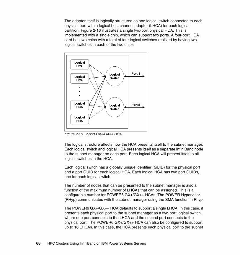
The adapter itself is logically structured as one logical switch connected to each physical port with a logical host channel adapter (LHCA) for each logical partition. Figure 2-16 illustrates a single two-port physical HCA. This is implemented with a single chip, which can support two ports. A four-port HCA card has two chips with a total of four logical switches realized by having two logical switches in each of the two chips.
Figure 2-16 2-port GX+/GX++ HCA
The logical structure affects how the HCA presents itself to the subnet manager. Each logical switch and logical HCA presents itself as a separate InfiniBand node to the subnet manager on each port. Each logical HCA will present itself to all logical switches in the HCA.
Each logical switch has a globally unique identifier (GUID) for the physical port and a port GUID for each logical HCA. Each logical HCA has two port GUIDs, one for each logical switch.
The number of nodes that can be presented to the subnet manager is also a function of the maximum number of LHCAs that can be assigned. This is a configurable number for POWER6 GX+/GX++ HCAs. The POWER Hypervisor (PHyp) communicates with the subnet manager using the SMA function in Phyp.
The POWER6 GX+/GX++ HCA defaults to support a single LHCA. In this case, it presents each physical port to the subnet manager as a two-port logical switch, where one port connects to the LHCA and the second port connects to the physical port. The POWER6 GX+/GX++ HCA can also be configured to support up to 16 LHCAs. In this case, the HCA presents each physical port to the subnet
68 HPC Clusters Using InfiniBand on IBM Power Systems Servers
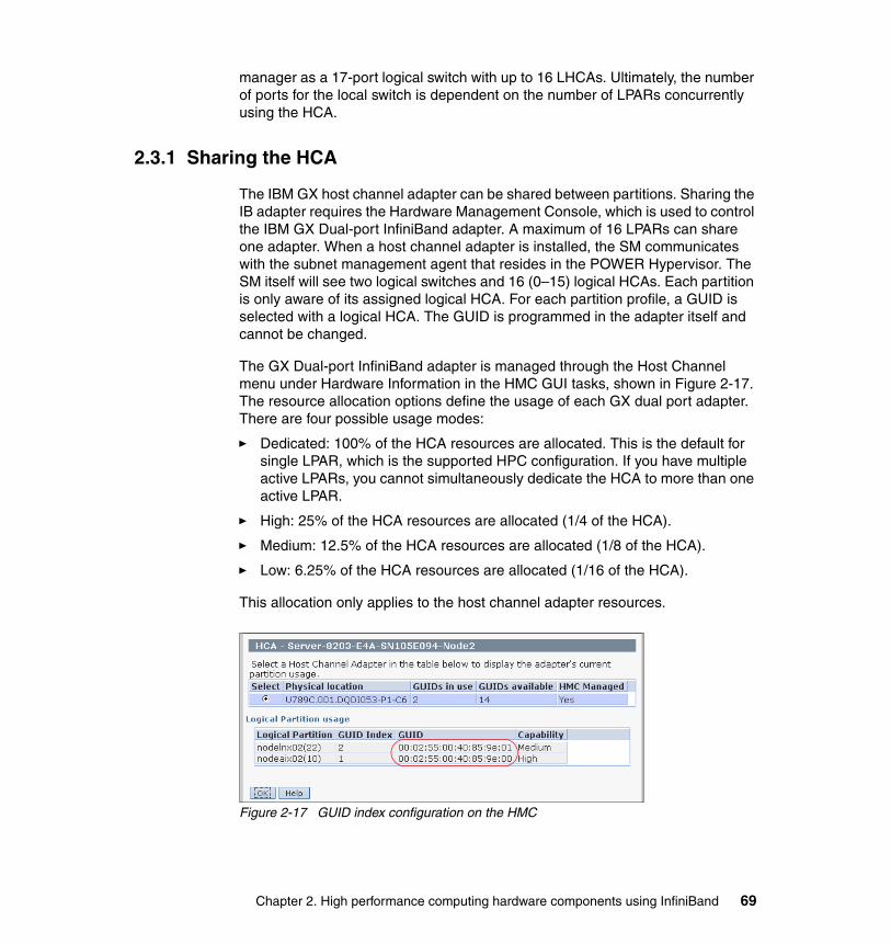
manager as a 17-port logical switch with up to 16 LHCAs. Ultimately, the number of ports for the local switch is dependent on the number of LPARs concurrently using the HCA.
2.3.1 Sharing the HCA
The IBM GX host channel adapter can be shared between partitions. Sharing the IB adapter requires the Hardware Management Console, which is used to control the IBM GX Dual-port InfiniBand adapter. A maximum of 16 LPARs can share one adapter. When a host channel adapter is installed, the SM communicates with the subnet management agent that resides in the POWER Hypervisor. The SM itself will see two logical switches and 16 (0–15) logical HCAs. Each partition is only aware of its assigned logical HCA. For each partition profile, a GUID is selected with a logical HCA. The GUID is programmed in the adapter itself and cannot be changed.
The GX Dual-port InfiniBand adapter is managed through the Host Channel menu under Hardware Information in the HMC GUI tasks, shown in Figure 2-17. The resource allocation options define the usage of each GX dual port adapter. There are four possible usage modes:
� Dedicated: 100% of the HCA resources are allocated. This is the default for single LPAR, which is the supported HPC configuration. If you have multiple active LPARs, you cannot simultaneously dedicate the HCA to more than one active LPAR.
� High: 25% of the HCA resources are allocated (1/4 of the HCA).
� Medium: 12.5% of the HCA resources are allocated (1/8 of the HCA).
� Low: 6.25% of the HCA resources are allocated (1/16 of the HCA).
This allocation only applies to the host channel adapter resources.
Figure 2-17 GUID index configuration on the HMC
Chapter 2. High performance computing hardware components using InfiniBand 69
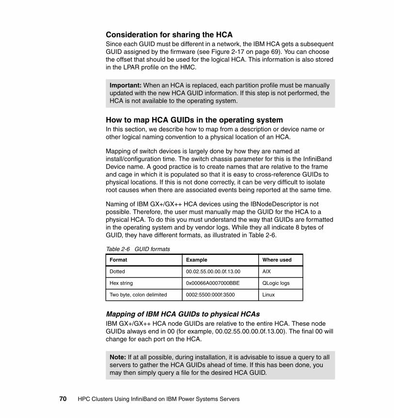
Consideration for sharing the HCASince each GUID must be different in a network, the IBM HCA gets a subsequent GUID assigned by the firmware (see Figure 2-17 on page 69). You can choose the offset that should be used for the logical HCA. This information is also stored in the LPAR profile on the HMC.
How to map HCA GUIDs in the operating systemIn this section, we describe how to map from a description or device name or other logical naming convention to a physical location of an HCA.
Mapping of switch devices is largely done by how they are named at install/configuration time. The switch chassis parameter for this is the InfiniBand Device name. A good practice is to create names that are relative to the frame and cage in which it is populated so that it is easy to cross-reference GUIDs to physical locations. If this is not done correctly, it can be very difficult to isolate root causes when there are associated events being reported at the same time.
Naming of IBM GX+/GX++ HCA devices using the IBNodeDescriptor is not possible. Therefore, the user must manually map the GUID for the HCA to a physical HCA. To do this you must understand the way that GUIDs are formatted in the operating system and by vendor logs. While they all indicate 8 bytes of GUID, they have different formats, as illustrated in Table 2-6.
Table 2-6 GUID formats
Mapping of IBM HCA GUIDs to physical HCAsIBM GX+/GX++ HCA node GUIDs are relative to the entire HCA. These node GUIDs always end in 00 (for example, 00.02.55.00.00.0f.13.00). The final 00 will change for each port on the HCA.
Important: When an HCA is replaced, each partition profile must be manually updated with the new HCA GUID information. If this step is not performed, the HCA is not available to the operating system.
Format Example Where used
Dotted 00.02.55.00.00.0f.13.00 AIX
Hex string 0x00066A0007000BBE QLogic logs
Two byte, colon delimited 0002:5500:000f:3500 Linux
Note: If at all possible, during installation, it is advisable to issue a query to all servers to gather the HCA GUIDs ahead of time. If this has been done, you may then simply query a file for the desired HCA GUID.
70 HPC Clusters Using InfiniBand on IBM Power Systems Servers
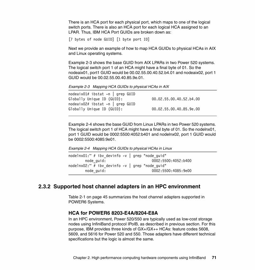
There is an HCA port for each physical port, which maps to one of the logical switch ports. There is also an HCA port for each logical HCA assigned to an LPAR. Thus, IBM HCA Port GUIDs are broken down as:
[7 bytes of node GUID] [1 byte port ID]
Next we provide an example of how to map HCA GUIDs to physical HCAs in AIX and Linux operating systems.
Example 2-3 shows the base GUID from AIX LPARs in two Power 520 systems. The logical switch port 1 of an HCA might have a final byte of 01. So the nodeaix01, port1 GUID would be 00.02.55.00.40.52.b4.01 and nodeaix02, port 1 GUID would be 00.02.55.00.40.85.9e.01.
Example 2-3 Mapping HCA GUIDs to physical HCAs in AIX
nodeaix01# ibstat -n | grep GUIDGlobally Unique ID (GUID): 00.02.55.00.40.52.b4.00nodeaix02# ibstat -n | grep GUIDGlobally Unique ID (GUID): 00.02.55.00.40.85.9e.00
Example 2-4 shows the base GUID from Linux LPARs in two Power 520 systems. The logical switch port 1 of HCA might have a final byte of 01. So the nodelnx01, port 1 GUID would be 0002:5500:4052:b401 and nodelnx02, port 1 GUID would be 0002:5500:4085:9e01.
Example 2-4 Mapping HCA GUIDs to physical HCAs in Linux
nodelnx01:~ # ibv_devinfo -v | grep "node_guid" node_guid: 0002:5500:4052:b400nodelnx02:~ # ibv_devinfo -v | grep "node_guid" node_guid: 0002:5500:4085:9e00
2.3.2 Supported host channel adapters in an HPC environment
Table 2-1 on page 45 summarizes the host channel adapters supported in POWER6 Systems.
HCA for POWER6 8203-E4A/8204-E8AIn an HPC environment, Power 520/550 are typically used as low-cost storage nodes using InfiniBand protocol IPoIB, as described in previous section. For this purpose, IBM provides three kinds of GX+/GX++ HCAs: feature codes 5608, 5609, and 5616 for Power 520 and 550. Those adapters have different technical specifications but the logic is almost the same.
Chapter 2. High performance computing hardware components using InfiniBand 71
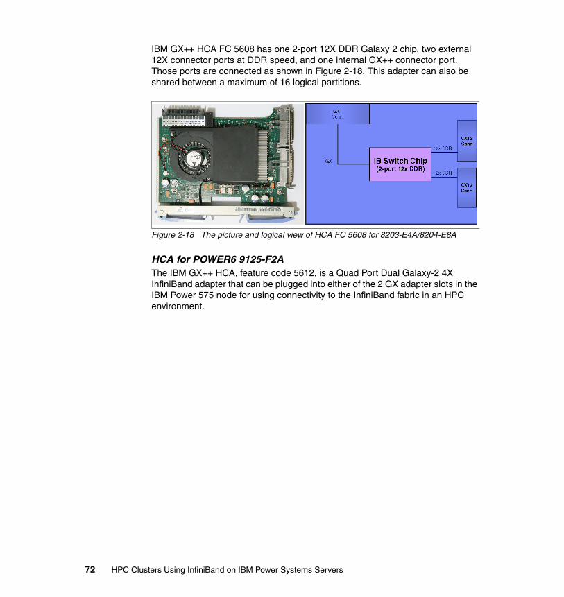
IBM GX++ HCA FC 5608 has one 2-port 12X DDR Galaxy 2 chip, two external 12X connector ports at DDR speed, and one internal GX++ connector port. Those ports are connected as shown in Figure 2-18. This adapter can also be shared between a maximum of 16 logical partitions.
Figure 2-18 The picture and logical view of HCA FC 5608 for 8203-E4A/8204-E8A
HCA for POWER6 9125-F2AThe IBM GX++ HCA, feature code 5612, is a Quad Port Dual Galaxy-2 4X InfiniBand adapter that can be plugged into either of the 2 GX adapter slots in the IBM Power 575 node for using connectivity to the InfiniBand fabric in an HPC environment.
72 HPC Clusters Using InfiniBand on IBM Power Systems Servers
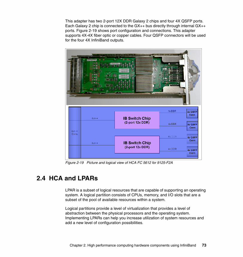
This adapter has two 2-port 12X DDR Galaxy 2 chips and four 4X QSFP ports. Each Galaxy 2 chip is connected to the GX++ bus directly through internal GX++ ports. Figure 2-19 shows port configuration and connections. This adapter supports 4X-4X fiber optic or copper cables. Four QSFP connectors will be used for the four 4X InfiniBand outputs.
Figure 2-19 Picture and logical view of HCA FC 5612 for 9125-F2A
2.4 HCA and LPARs
LPAR is a subset of logical resources that are capable of supporting an operating system. A logical partition consists of CPUs, memory, and I/O slots that are a subset of the pool of available resources within a system.
Logical partitions provide a level of virtualization that provides a level of abstraction between the physical processors and the operating system. Implementing LPARs can help you increase utilization of system resources and add a new level of configuration possibilities.
Chapter 2. High performance computing hardware components using InfiniBand 73
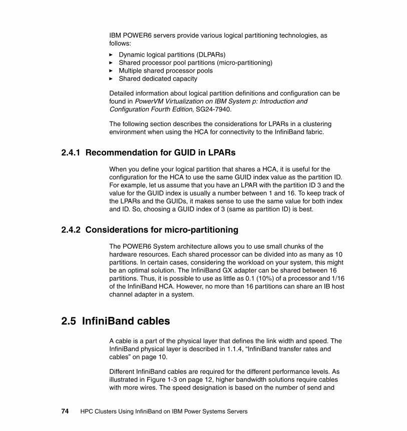
IBM POWER6 servers provide various logical partitioning technologies, as follows:
� Dynamic logical partitions (DLPARs)� Shared processor pool partitions (micro-partitioning)� Multiple shared processor pools� Shared dedicated capacity
Detailed information about logical partition definitions and configuration can be found in PowerVM Virtualization on IBM System p: Introduction and Configuration Fourth Edition, SG24-7940.
The following section describes the considerations for LPARs in a clustering environment when using the HCA for connectivity to the InfiniBand fabric.
2.4.1 Recommendation for GUID in LPARs
When you define your logical partition that shares a HCA, it is useful for the configuration for the HCA to use the same GUID index value as the partition ID. For example, let us assume that you have an LPAR with the partition ID 3 and the value for the GUID index is usually a number between 1 and 16. To keep track of the LPARs and the GUIDs, it makes sense to use the same value for both index and ID. So, choosing a GUID index of 3 (same as partition ID) is best.
2.4.2 Considerations for micro-partitioning
The POWER6 System architecture allows you to use small chunks of the hardware resources. Each shared processor can be divided into as many as 10 partitions. In certain cases, considering the workload on your system, this might be an optimal solution. The InfiniBand GX adapter can be shared between 16 partitions. Thus, it is possible to use as little as 0.1 (10%) of a processor and 1/16 of the InfiniBand HCA. However, no more than 16 partitions can share an IB host channel adapter in a system.
2.5 InfiniBand cables
A cable is a part of the physical layer that defines the link width and speed. The InfiniBand physical layer is described in 1.1.4, “InfiniBand transfer rates and cables” on page 10.
Different InfiniBand cables are required for the different performance levels. As illustrated in Figure 1-3 on page 12, higher bandwidth solutions require cables with more wires. The speed designation is based on the number of send and
74 HPC Clusters Using InfiniBand on IBM Power Systems Servers
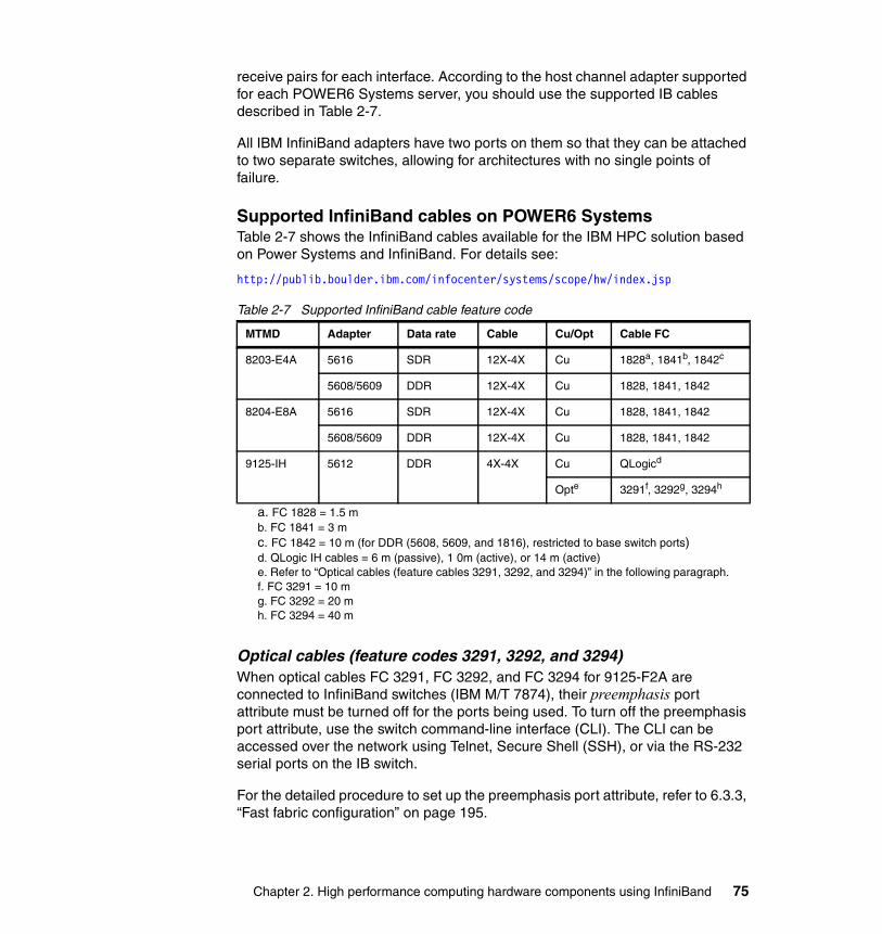
receive pairs for each interface. According to the host channel adapter supported for each POWER6 Systems server, you should use the supported IB cables described in Table 2-7.
All IBM InfiniBand adapters have two ports on them so that they can be attached to two separate switches, allowing for architectures with no single points of failure.
Supported InfiniBand cables on POWER6 SystemsTable 2-7 shows the InfiniBand cables available for the IBM HPC solution based on Power Systems and InfiniBand. For details see:
http://publib.boulder.ibm.com/infocenter/systems/scope/hw/index.jsp
Table 2-7 Supported InfiniBand cable feature code
Optical cables (feature codes 3291, 3292, and 3294)When optical cables FC 3291, FC 3292, and FC 3294 for 9125-F2A are connected to InfiniBand switches (IBM M/T 7874), their preemphasis port attribute must be turned off for the ports being used. To turn off the preemphasis port attribute, use the switch command-line interface (CLI). The CLI can be accessed over the network using Telnet, Secure Shell (SSH), or via the RS-232 serial ports on the IB switch.
For the detailed procedure to set up the preemphasis port attribute, refer to 6.3.3, “Fast fabric configuration” on page 195.
MTMD Adapter Data rate Cable Cu/Opt Cable FC
8203-E4A 5616 SDR 12X-4X Cu 1828a, 1841b, 1842c
a. FC 1828 = 1.5 mb. FC 1841 = 3 mc. FC 1842 = 10 m (for DDR (5608, 5609, and 1816), restricted to base switch ports)
5608/5609 DDR 12X-4X Cu 1828, 1841, 1842
8204-E8A 5616 SDR 12X-4X Cu 1828, 1841, 1842
5608/5609 DDR 12X-4X Cu 1828, 1841, 1842
9125-IH 5612 DDR 4X-4X Cu QLogicd
d. QLogic IH cables = 6 m (passive), 1 0m (active), or 14 m (active)
Opte
e. Refer to “Optical cables (feature cables 3291, 3292, and 3294)” in the following paragraph.
3291f, 3292g, 3294h
f. FC 3291 = 10 mg. FC 3292 = 20 mh. FC 3294 = 40 m
Chapter 2. High performance computing hardware components using InfiniBand 75
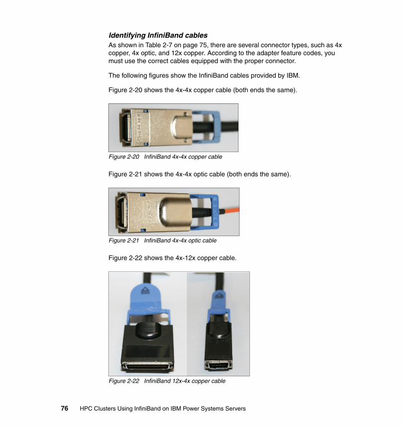
Identifying InfiniBand cablesAs shown in Table 2-7 on page 75, there are several connector types, such as 4x copper, 4x optic, and 12x copper. According to the adapter feature codes, you must use the correct cables equipped with the proper connector.
The following figures show the InfiniBand cables provided by IBM.
Figure 2-20 shows the 4x-4x copper cable (both ends the same).
Figure 2-20 InfiniBand 4x-4x copper cable
Figure 2-21 shows the 4x-4x optic cable (both ends the same).
Figure 2-21 InfiniBand 4x-4x optic cable
Figure 2-22 shows the 4x-12x copper cable.
Figure 2-22 InfiniBand 12x-4x copper cable
76 HPC Clusters Using InfiniBand on IBM Power Systems Servers
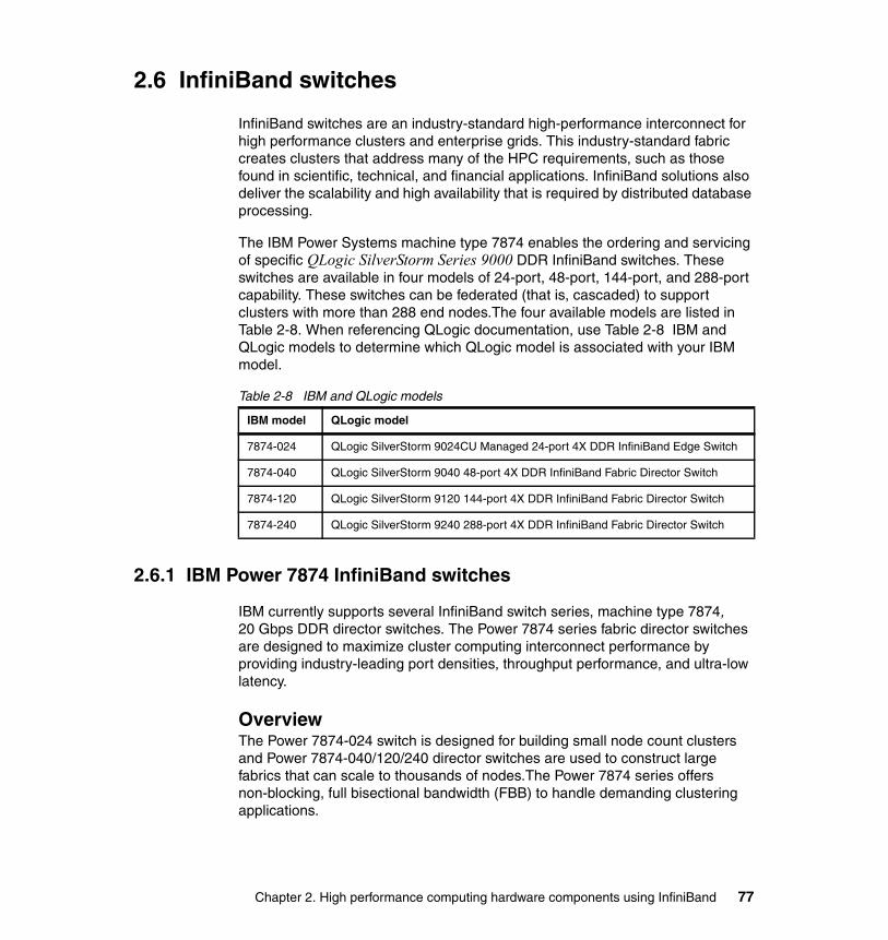
2.6 InfiniBand switches
InfiniBand switches are an industry-standard high-performance interconnect for high performance clusters and enterprise grids. This industry-standard fabric creates clusters that address many of the HPC requirements, such as those found in scientific, technical, and financial applications. InfiniBand solutions also deliver the scalability and high availability that is required by distributed database processing.
The IBM Power Systems machine type 7874 enables the ordering and servicing of specific QLogic SilverStorm Series 9000 DDR InfiniBand switches. These switches are available in four models of 24-port, 48-port, 144-port, and 288-port capability. These switches can be federated (that is, cascaded) to support clusters with more than 288 end nodes.The four available models are listed in Table 2-8. When referencing QLogic documentation, use Table 2-8 IBM and QLogic models to determine which QLogic model is associated with your IBM model.
Table 2-8 IBM and QLogic models
2.6.1 IBM Power 7874 InfiniBand switches
IBM currently supports several InfiniBand switch series, machine type 7874, 20 Gbps DDR director switches. The Power 7874 series fabric director switches are designed to maximize cluster computing interconnect performance by providing industry-leading port densities, throughput performance, and ultra-low latency.
OverviewThe Power 7874-024 switch is designed for building small node count clusters and Power 7874-040/120/240 director switches are used to construct large fabrics that can scale to thousands of nodes.The Power 7874 series offers non-blocking, full bisectional bandwidth (FBB) to handle demanding clustering applications.
IBM model QLogic model
7874-024 QLogic SilverStorm 9024CU Managed 24-port 4X DDR InfiniBand Edge Switch
7874-040 QLogic SilverStorm 9040 48-port 4X DDR InfiniBand Fabric Director Switch
7874-120 QLogic SilverStorm 9120 144-port 4X DDR InfiniBand Fabric Director Switch
7874-240 QLogic SilverStorm 9240 288-port 4X DDR InfiniBand Fabric Director Switch
Chapter 2. High performance computing hardware components using InfiniBand 77

Each director switch model, 7874-040/120/240, consists of a chassis frame, one or more spines4, and a number of leaf5 modules. The spines and leafs, as well as fan trays and power supply units, are interchangeable within a switch and across the entire IBM Power 7874 InfiniBand switch series line.
Both the spines and the leafs have inter-switch link (ISL) ports that connect to the backplane of the chassis providing the fabric leaf-to-leaf internal connections for each switch. Each leaf has 12 cable ports and 12 internal ports for a total of 24 ports, and all of these ports are visible when monitoring the system. Each leaf contains one switch chip for routing traffic. Each spine has 48 internal switch ports that connect to the backplane and two switch chips for routing traffic.
The Power 7874 series spines can be either managed (including a management module) or unmanaged (without a management module). The Power 7874 series switches with more than two spine slots can accommodate two managed spines (two per hemisphere for 7874-240) to deliver redundant management.
The spines contain the management firmware for the chassis, so when the firmware is updated on the spines, the firmware for each leaf chip is updated as well.
These products are managed by the QLogic InfiniBand Fabric Suite Fabric Manager and the QLogic InfiniBand Fabric Suite FastFabric Toolset bundled in the QLogic InfiniBand Fabric Suite (IFS). This management suite provides system and fabric management with a consistent user interface for topology, configuration, performance, and fabric diagnostics. The management software is installed on a host running Linux and connected to the switches through a Qlogic InfiniBand Adapter and appropriate cables. For more information about the QLogic InfiniBand Fabric Suite, refer to 3.2.2, “Fabric Management Server” on page 103.
Note: Oversubscribed configuration is also supported if trade-off between performance and cost is desired.
4 Spine: management module located inside a Power 7874 switch. Core switch is located inside a Power 7874 switch.
Note: There are managed and un-managed spines.5 Leaf: edge switch located inside a Power 7874 switch.
78 HPC Clusters Using InfiniBand on IBM Power Systems Servers
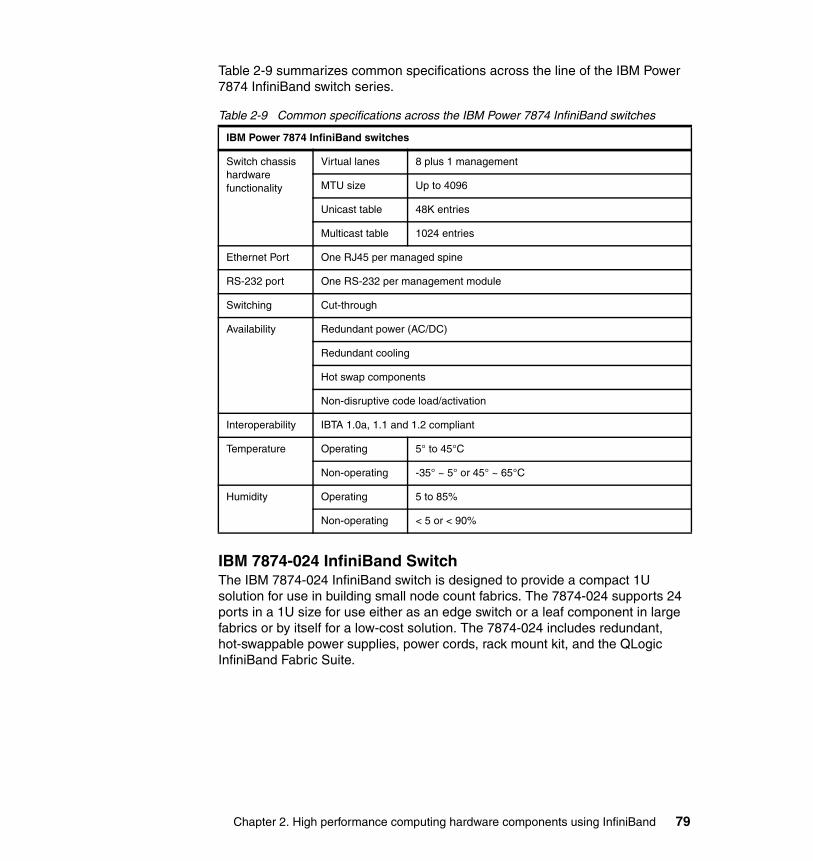
Table 2-9 summarizes common specifications across the line of the IBM Power 7874 InfiniBand switch series.
Table 2-9 Common specifications across the IBM Power 7874 InfiniBand switches
IBM 7874-024 InfiniBand SwitchThe IBM 7874-024 InfiniBand switch is designed to provide a compact 1U solution for use in building small node count fabrics. The 7874-024 supports 24 ports in a 1U size for use either as an edge switch or a leaf component in large fabrics or by itself for a low-cost solution. The 7874-024 includes redundant, hot-swappable power supplies, power cords, rack mount kit, and the QLogic InfiniBand Fabric Suite.
IBM Power 7874 InfiniBand switches
Switch chassis hardware functionality
Virtual lanes 8 plus 1 management
MTU size Up to 4096
Unicast table 48K entries
Multicast table 1024 entries
Ethernet Port One RJ45 per managed spine
RS-232 port One RS-232 per management module
Switching Cut-through
Availability Redundant power (AC/DC)
Redundant cooling
Hot swap components
Non-disruptive code load/activation
Interoperability IBTA 1.0a, 1.1 and 1.2 compliant
Temperature Operating 5° to 45°C
Non-operating -35° ~ 5° or 45° ~ 65°C
Humidity Operating 5 to 85%
Non-operating < 5 or < 90%
Chapter 2. High performance computing hardware components using InfiniBand 79
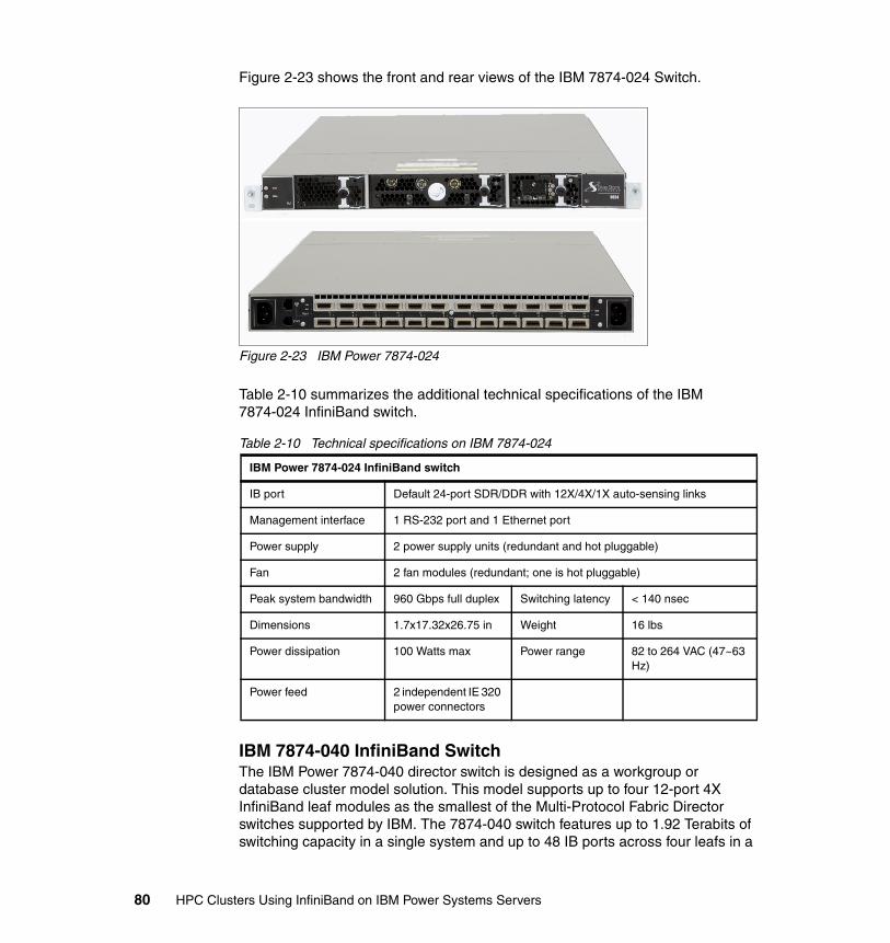
Figure 2-23 shows the front and rear views of the IBM 7874-024 Switch.
Figure 2-23 IBM Power 7874-024
Table 2-10 summarizes the additional technical specifications of the IBM 7874-024 InfiniBand switch.
Table 2-10 Technical specifications on IBM 7874-024
IBM 7874-040 InfiniBand SwitchThe IBM Power 7874-040 director switch is designed as a workgroup or database cluster model solution. This model supports up to four 12-port 4X InfiniBand leaf modules as the smallest of the Multi-Protocol Fabric Director switches supported by IBM. The 7874-040 switch features up to 1.92 Terabits of switching capacity in a single system and up to 48 IB ports across four leafs in a
IBM Power 7874-024 InfiniBand switch
IB port Default 24-port SDR/DDR with 12X/4X/1X auto-sensing links
Management interface 1 RS-232 port and 1 Ethernet port
Power supply 2 power supply units (redundant and hot pluggable)
Fan 2 fan modules (redundant; one is hot pluggable)
Peak system bandwidth 960 Gbps full duplex Switching latency < 140 nsec
Dimensions 1.7x17.32x26.75 in Weight 16 lbs
Power dissipation 100 Watts max Power range 82 to 264 VAC (47~63 Hz)
Power feed 2 independent IE 320 power connectors
80 HPC Clusters Using InfiniBand on IBM Power Systems Servers
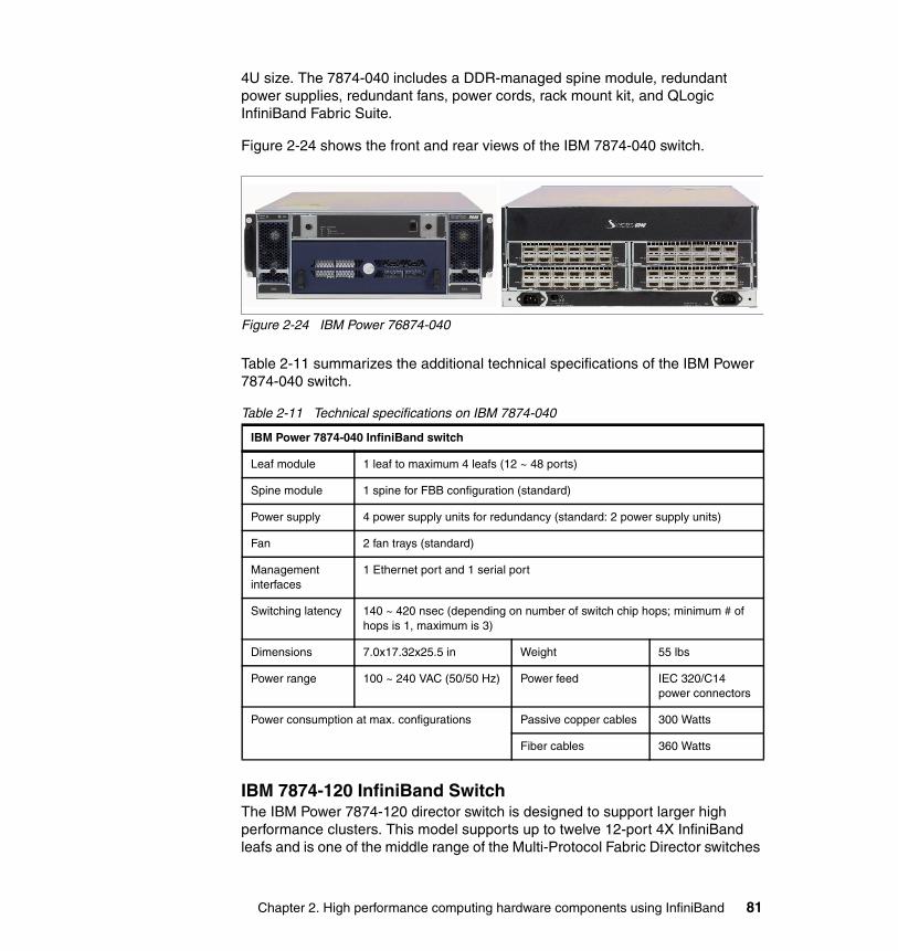
4U size. The 7874-040 includes a DDR-managed spine module, redundant power supplies, redundant fans, power cords, rack mount kit, and QLogic InfiniBand Fabric Suite.
Figure 2-24 shows the front and rear views of the IBM 7874-040 switch.
Figure 2-24 IBM Power 76874-040
Table 2-11 summarizes the additional technical specifications of the IBM Power 7874-040 switch.
Table 2-11 Technical specifications on IBM 7874-040
IBM 7874-120 InfiniBand SwitchThe IBM Power 7874-120 director switch is designed to support larger high performance clusters. This model supports up to twelve 12-port 4X InfiniBand leafs and is one of the middle range of the Multi-Protocol Fabric Director switches
IBM Power 7874-040 InfiniBand switch
Leaf module 1 leaf to maximum 4 leafs (12 ~ 48 ports)
Spine module 1 spine for FBB configuration (standard)
Power supply 4 power supply units for redundancy (standard: 2 power supply units)
Fan 2 fan trays (standard)
Management interfaces
1 Ethernet port and 1 serial port
Switching latency 140 ~ 420 nsec (depending on number of switch chip hops; minimum # of hops is 1, maximum is 3)
Dimensions 7.0x17.32x25.5 in Weight 55 lbs
Power range 100 ~ 240 VAC (50/50 Hz) Power feed IEC 320/C14 power connectors
Power consumption at max. configurations Passive copper cables 300 Watts
Fiber cables 360 Watts
Chapter 2. High performance computing hardware components using InfiniBand 81

supported by IBM. This switch features up to 5.76 Terabits of switching capacity in a single system and up to 144 IB ports across 12 leafs in a 7U size.
Figure 2-25 shows the front and rear views of the IBM Power 7874-120 switch.
Figure 2-25 IBM Power 7874-120
Table 2-12 summarizes the additional technical specifications of the IBM Power 7874-120 switch.
Table 2-12 Technical specifications on IBM 7874-120
IBM Power 7874-120 InfiniBand switch
Leaf module 1 leaf to maximum 12 leafs (12 ports to maximum 144 ports)
Spine module Default 1 managed spine (optional 3 spines: 2 managed spine and 1 non-managed spine, for FBB configuration)a
a. Managed spine should be on slots 1 or 2, or both
Power supply Default 3 power supply units (optional 6 power supply units for redundancy)
Fan Default 2 fan trays (optional 4 fan trays for redundancy)
Management interface
Up to 2 Ethernet and 2 serial ports (depends on number of managed spine)
Switching latency 140 ~ 420 nsec (depending on number of switch chip hops; minimum # of hops is 1, maximum is 3).
Dimensions 12.25x17.32x25.5 in Weight 100 lbs
Power range 100 ~ 240 VAC (50/50 Hz) Power feed IEC 320/C14 power connectors
Power consumption at max. configurations Passive copper cables 840 Watts
Fiber cables 1026 Watts
82 HPC Clusters Using InfiniBand on IBM Power Systems Servers

IBM 7874-240 InfiniBand SwitchThe IBM Power 7874-240 switch is the largest of the Multi-Protocol Fabric Director switches supported by IBM. This switch features up to 11.52 Terabits of switching capacity in a single system and up to 288 IB ports across 24 leafs (12 in each hemisphere) in a 14U size.
Figure 2-26 shows the front and rear views of the IBM Power 7874-240 switch.
Figure 2-26 IBM Power 7874-240
Table 2-13 summarizes the additional technical specifications of the IBM Power 7874-240 switch.
Table 2-13 Technical specifications on IBM 7874-240
IBM Power 7874-240 InfiniBand switch
Leaf module 1 leaf to maximum 24 leafs (12 ports to maximum 288 ports)
Spine module Default 1 managed spine (optional 6 spines: 4 managed spine and 2 non-managed spine, for FBB configuration)a
Power supply Default 6 power supply units, 3 for lower hemisphere, 3 for upper hemisphere (optional 12 power supply units for redundancy)
Fan Default 8 fan trays
Management interface
Up to 4 Ethernet and 4 serial ports (depends on number of managed spine)
Chapter 2. High performance computing hardware components using InfiniBand 83
2.6.2 Host subnet manager
High performance cluster configurations, when configuration is greater than 144 nodes, require the use of an external Linux server running the host subnet manager (HSM) code. This runs on an IBM System x3550 or IBM System x3650, with InfiniBand host channel adapter and InfiniBand cable.
At least two servers each with two host channel adapters are required for redundancy and failover. Each host can manage up to four fabrics using two dual-port HCAs. So, two servers can manage four fabrics with redundancy. Four servers can manage eight fabrics with redundancy.
The InfiniBand host channel adapters and the InfiniBand cables for the HSM servers must be obtained directly from QLogic Corporation. The HSM servers run the QLogic FastFabric Suite, which is downloadable from the QLogic IBM Supported Software Web site:
http://support.qlogic.com/support/oem_ibm.asp
For more information about QLogic Fabric Manager, refer to 3.2.2, “Fabric Management Server” on page 103.
Hardware requirements for QLogic Fabric ManagerThe following are the hardware requirements for running the QLogic Fabric Manager code:
� Platform: IBM system x3550 or x3650� Cable: CX4-CX4 InfiniBand cables from QLogic corporation� Adapter: 7104-HCA-LPX2P-DDR from QLogic corporation
For more information about the adapter and cables provided from QLogic see the following two sections
Switching latency 140 ~ 420 nsec (depending on number of switch chip hops; minimum # of hops is 1, maximum is 3)
Dimensions 24.5x17.32x25.5 in Weight 180 lbs
Power range 100 ~ 240 VAC (50/50 Hz) Power feed IEC 320/C14 power connectors
Power consumption at max. configurations Passive copper cables 1680 Watts
Fiber cables 2052 Watts
a. Managed spine should be on slots 1, 2, 6, 5
IBM Power 7874-240 InfiniBand switch
84 HPC Clusters Using InfiniBand on IBM Power Systems Servers
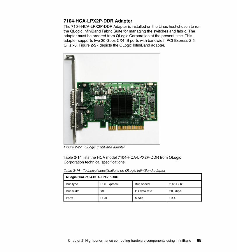
7104-HCA-LPX2P-DDR AdapterThe 7104-HCA-LPX2P-DDR Adapter is installed on the Linux host chosen to run the QLogic InfiniBand Fabric Suite for managing the switches and fabric. The adapter must be ordered from QLogic Corporation at the present time. This adapter supports two 20 Gbps CX4 IB ports with bandwidth PCI Express 2.5 GHz x8. Figure 2-27 depicts the QLogic InfiniBand adapter.
Figure 2-27 QLogic InfiniBand adapter
Table 2-14 lists the HCA model 7104-HCA-LPX2P-DDR from QLogic Corporation technical specifications.
Table 2-14 Technical specifications on QLogic InfiniBand adapter
QLogic HCA 7104-HCA-LPX2P-DDR
Bus type PCI Express Bus speed 2.65 GHz
Bus width x8 I/O data rate 20 Gbps
Ports Dual Media CX4
Chapter 2. High performance computing hardware components using InfiniBand 85
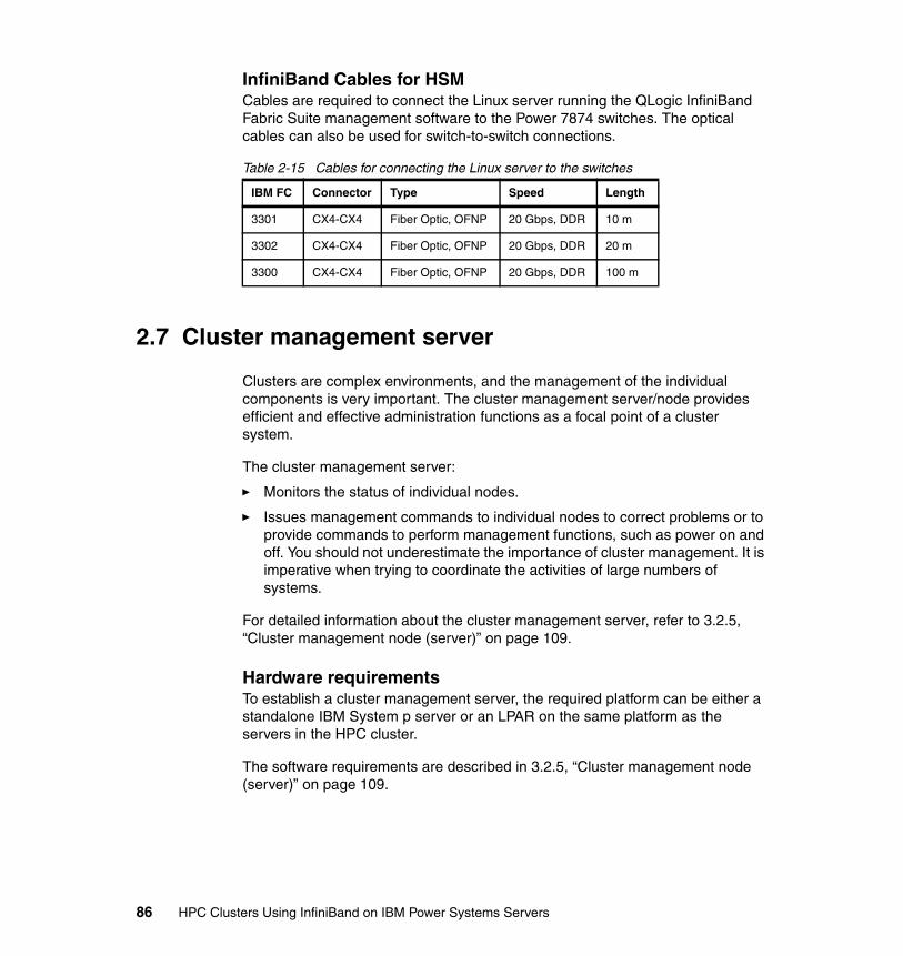
InfiniBand Cables for HSMCables are required to connect the Linux server running the QLogic InfiniBand Fabric Suite management software to the Power 7874 switches. The optical cables can also be used for switch-to-switch connections.
Table 2-15 Cables for connecting the Linux server to the switches
2.7 Cluster management server
Clusters are complex environments, and the management of the individual components is very important. The cluster management server/node provides efficient and effective administration functions as a focal point of a cluster system.
The cluster management server:
� Monitors the status of individual nodes.
� Issues management commands to individual nodes to correct problems or to provide commands to perform management functions, such as power on and off. You should not underestimate the importance of cluster management. It is imperative when trying to coordinate the activities of large numbers of systems.
For detailed information about the cluster management server, refer to 3.2.5, “Cluster management node (server)” on page 109.
Hardware requirementsTo establish a cluster management server, the required platform can be either a standalone IBM System p server or an LPAR on the same platform as the servers in the HPC cluster.
The software requirements are described in 3.2.5, “Cluster management node (server)” on page 109.
IBM FC Connector Type Speed Length
3301 CX4-CX4 Fiber Optic, OFNP 20 Gbps, DDR 10 m
3302 CX4-CX4 Fiber Optic, OFNP 20 Gbps, DDR 20 m
3300 CX4-CX4 Fiber Optic, OFNP 20 Gbps, DDR 100 m
86 HPC Clusters Using InfiniBand on IBM Power Systems Servers

Chapter 3. Technical description of software components
This chapter provides a software (SW) technical overview of the IBM High Performance Computing (HPC) solutions based on the IBM POWER6 Systems and InfiniBand. We describe the software components (stack) that are used to enable, manage, and exploit hardware (HW) infrastructure (IBM System p servers, InfiniBand switches) in an HPC environment.
This chapter describes the following:
� AIX and Linux on IBM POWER6 Systems using InfiniBand� Management subsystem overview (cluster, fabric)� HPC InfiniBand application stack overview
3
© Copyright IBM Corp. 2009. All rights reserved. 87
3.1 AIX and Linux on POWER using InfiniBand
This section describes the components of the HPC solution for AIX and Linux on POWER using InfiniBand as the cluster interconnect.
The IBM objective is to provide an industrial strength high performance computing offering for AIX on POWER using InfiniBand switches as the high-speed cluster interconnect. The InfiniBand interconnect technology is particularly well suited for scalable high-bandwidth, low-latency applications such as scientific and engineering computation.
The components that IBM provides constitute a complete high performance computing solution consisting of IBM program products adapted to take advantage of InfiniBand. All components were integrated and tested together to develop a quality product. This testing included the IBM program products and the InfiniBand components.
3.1.1 Solution components
This solution includes:
� GX/GX++ DDR adapters� IBM 7874-XXX InfiniBand switches� IBM Power Architecture technology-based servers: p520, p550, p575� IBM General Parallel File System (GPFS)� IBM Tivoli® Workload Scheduler LoadLeveler (LL)� IBM Parallel Environment for AIX and Linux on POWER Systems� IBM Parallel Engineering Scientific Subroutine Library� Cluster systems Management (CSM) and xCAT21 for AIX/Linux
These components have been integrated and qualified on servers running AIX and Linux on POWER. The IBM Message Passing Interface (MPI) and low-level application programming interface (LAPI) are layered over the InfiniBand (IB) user verbs library and the IBM use of the IP over IB (IPoIB) driver.
1 xCAT2 means Extreme Cluster Administration Tool Version 2. This is an open source cluster management tool from IBM, released under the Eclipse Public License Agreement. We recommend xCAT for all new HPC cluster deployments.
88 HPC Clusters Using InfiniBand on IBM Power Systems Servers
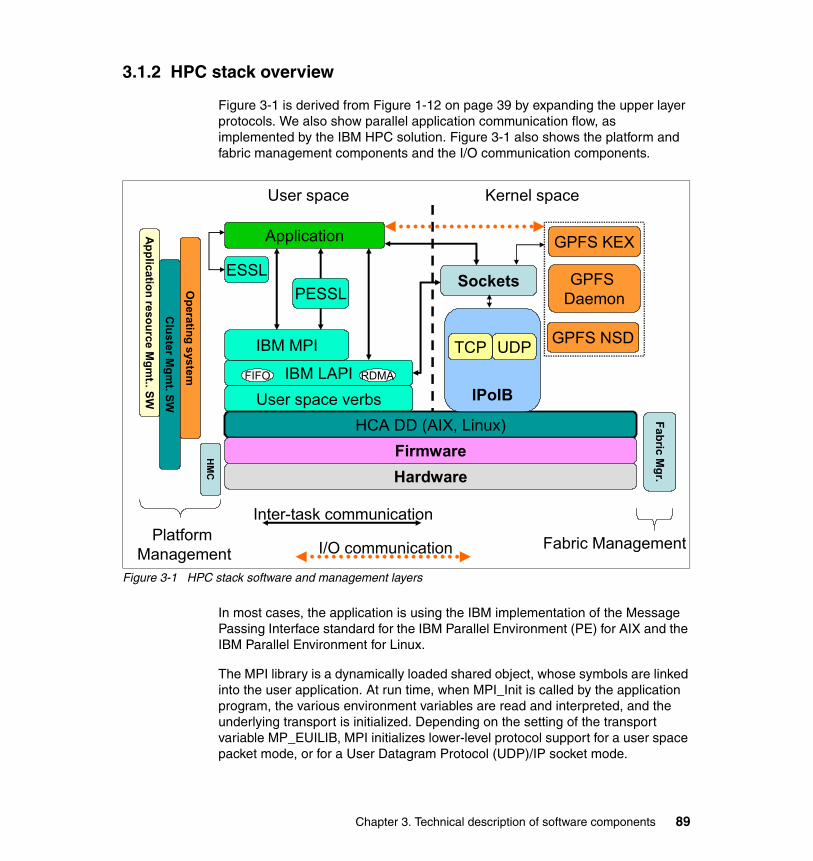
3.1.2 HPC stack overview
Figure 3-1 is derived from Figure 1-12 on page 39 by expanding the upper layer protocols. We also show parallel application communication flow, as implemented by the IBM HPC solution. Figure 3-1 also shows the platform and fabric management components and the I/O communication components.
Figure 3-1 HPC stack software and management layers
In most cases, the application is using the IBM implementation of the Message Passing Interface standard for the IBM Parallel Environment (PE) for AIX and the IBM Parallel Environment for Linux.
The MPI library is a dynamically loaded shared object, whose symbols are linked into the user application. At run time, when MPI_Init is called by the application program, the various environment variables are read and interpreted, and the underlying transport is initialized. Depending on the setting of the transport variable MP_EUILIB, MPI initializes lower-level protocol support for a user space packet mode, or for a User Datagram Protocol (UDP)/IP socket mode.
Application resource M
gmt.. SW
Application
ESSL
IBM LAPIUser space verbs
IBM MPI
HCA DD (AIX, Linux)FirmwareHardware
Sockets
IPoIB
PESSL
GPFS KEX
GPFS NSD
GPFS Daemon
UDPTCP
I/O communication
Inter-task communication
Cluster M
gmt. SW
Operating system
HM
C
Fabric Mgr.
Platform Management
Fabric Management
FIFO RDMA
Kernel spaceUser space
Chapter 3. Technical description of software components 89

The PE MPI layer is built on top of the low-level application programming interface, which is a message-passing API. Although MPI manages point-to-point messages, part of this management is in the LAPI lower level protocol (LLP), which provides a reliable message delivery layer and a mechanism for asynchronous progress in MPI. Because LAPI runs above an unreliable packet layer, LAPI must deal with detecting and retransmitting any lost packet.
LAPI supports three communication modes or message transport mechanisms (although user space (US) and UDP/IP modes are mutually exclusive for any given job):
� User space using the user space verbs to implement first in, first out (FIFO) and Remote Direct Memory Access (RDMA) protocols. It is basically an optimized use of a communication adapter in which the tasks of a parallel job are able to submit a message for a task on another node to the adapter or get a message from another task from the adapter, both without kernel involvement.
LAPI FIFO protocol handles message packets from 2 K to 4 K depending on the IB switch setting and uses unreliable datagram (UD) queue pairs (QPs).
LAPI RDMA protocol is typically used for bulk message transfer, which is especially useful for applications that transfer relatively large amounts of data (more than 150 KB) in a single call or that overlap computation and communication because the CPU is no longer required to copy data. LAPI creates the reliable connection (RC) QPs for a given pair of tasks when RDMA is used.
� User datagram protocol/internet protocol using IPoIB is used for tasks on nodes that are connected with an IP network. UDP/IP involves the kernel in each node-to-node message.
� Shared memory is used for tasks on the same node (as processes under the same operating system image).
3.1.3 AIX IB software architecture
This section describes the AIX implementation of the InfiniBand device drivers.
AIX IB infrastructure driverThe IB infrastructure driver on AIX is the InfiniBand Communications Manager (ICM). The ICM is responsible for establishing, maintaining, and releasing connection-oriented channels, as well as providing service ID resolution for unreliable datagram users.
90 HPC Clusters Using InfiniBand on IBM Power Systems Servers
ICM subcomponentsThe AIX InfiniBand Communication Manager contains three subcomponents:
� Connection manager (CM) responsible for connections and UD services
� Subnet administrator (SA) responsible for path and multicast services
� Queue multiplexer (QMX) responsible for special queue pair and event handling
AIX interface driverThe InfiniBand interface driver on AIX is the IPoIB driver.
IPoIBFor IPoIB:
� This new implementation allows transporting TCP/IP packets over the InfiniBand infrastructure.
� The transport will be accomplished encapsulating IP packets over IB packets using a network interface.
� Configuration is similar to the Ethernet Interface.
� This is important because customers feel more comfortable using IP addressing than IB addressing.
Link layer informationAn InfiniBand packet over the UD mode needs certain link layer information determined before an IP packet may be transmitted across the IPoIB link. The following information is needed:
� Local identifier (LID)
The LID is always needed. A packet always includes the local route header (LRH) that is targeted at the remote node's LID.
� Global identifier (GID)
The GID is not needed when exchanging information within an IB subnet although it may be included in any packet. It is used to map to the LID by the subnet manager (SM).
� Queue pair number (QPN)
Every unicast UD communication is always directed to a particular queue pair (QP) at the peer.
Chapter 3. Technical description of software components 91
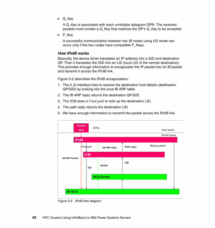
� Q_Key
A Q_Key is associated with each unreliable datagram QPN. The received packets must contain a Q_Key that matches the QP's Q_Key to be accepted.
� P_Key
A successful communication between two IB nodes using UD mode can occur only if the two nodes have compatible P_Keys.
How IPoIB worksBasically, the device driver translates an IP address into a GID and destination QP. Then it translates the GID into an LID (local LID of the remote destination). This provides enough information to encapsulate the IP packet into an IB packet and transmit it across the IPoIB link.
Figure 3-2 describes the IPoIB encapsulation:
1. The if_ib interface tries to resolve the destination host details (destination QP/GID) by looking into the local IB ARP table.
2. The IB ARP reply returns the destination QP/GID.
3. The ICM does a Find path to look up the destination LID.
4. The path reply returns the destination LID.
5. We have enough information to transmit the packet across the IPoIB link.
Figure 3-2 IPoIB flow diagram
Socket
APIs
IPoIB
HCA Driver
IB HCA
ICM
(ping)
(IB ARP Packet)
(IB ARP reply)Find path (Path reply) IB/ping packet
User space
Kernel space
QP/GIDGID
LID
92 HPC Clusters Using InfiniBand on IBM Power Systems Servers
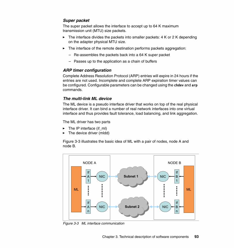
Super packetThe super packet allows the interface to accept up to 64 K maximum transmission unit (MTU) size packets.
� The interface divides the packets into smaller packets: 4 K or 2 K depending on the adapter physical MTU size.
� The interface of the remote destination performs packets aggregation:
– Re-assembles the packets back into a 64 K super packet
– Passes up to the application as a chain of buffers
ARP timer configuration Complete Address Resolution Protocol (ARP) entries will expire in 24 hours if the entries are not used. Incomplete and complete ARP expiration timer values can be configured. Configurable parameters can be changed using the chdev and arp commands.
The multi-link ML deviceThe ML device is a pseudo interface driver that works on top of the real physical interface driver. It can bind a number of real network interfaces into one virtual interface and thus provides fault tolerance, load balancing, and link aggregation.
The ML driver has two parts
� The IP interface (if_ml) � The device driver (mldd)
Figure 3-3 illustrates the basic idea of ML with a pair of nodes, node A and node B.
Figure 3-3 ML interface communication
NODE A NODE B
Subnet 1Subnet 1
ML
IfA1
ML
NIC NIC
Subnet 2Subnet 2NIC NICIfAn
IfBn
IfB1
Chapter 3. Technical description of software components 93

Nodes A and B can communicate with each other through the ML interface. Which underlying physical interface or route a packet actually goes through is taken care of by the ML device driver, whose main tasks are route discovery and route monitoring. These tasks are done by exchanging ML messages between node pairs.
The AIX ML filesetThe fileset needed for the ML device is:
devices.common.IBM.ml
AIX HCAD device driverThe HCAD device driver is a GX+/GX++ device driver and supports the following:
� GX/GX++ DDR adapter with up to 4 K physical MTU packets
� Adapter line speeds of 4X and 12X (1x = 2.5 Gbps, 12X supported as of November 2008)
� Up to 60 Gbps (hardware speed) using the 12X DDR adapter
� UD low-latency queue pairs
– Standard UD send queue
– Low latency message receive queue
� Large page sizes of memory regions
– Register large pages of memory regions to the adapter.
– Divide the user-allocated memory region page size into the next highest page size that the adapter supports but smaller or equal to the user-allocated memory region page size.
AIX IB filesetsIn AIX 6.1, there are two filesets that must be installed to install and configure the GX InfiniBand adapter and related devices. The filesets needed are:
� devices.chrp.IBM.lhca.rte� devices.common.IBM.ib.rte
The devices.chrp.IBM.lhca.rte fileset contains the files (configuration, libraries, and commands) to support the GX IB adapter. It contains the gxibdd kernel extension and is used to create and manage the IB Host Channel Adapter Device (HCAD) iba0.
The devices.common.IBM.ib.rte fileset contains the files (configuration, libraries, and commands) to support the InfiniBand Connection Manager and the IPoIB
94 HPC Clusters Using InfiniBand on IBM Power Systems Servers
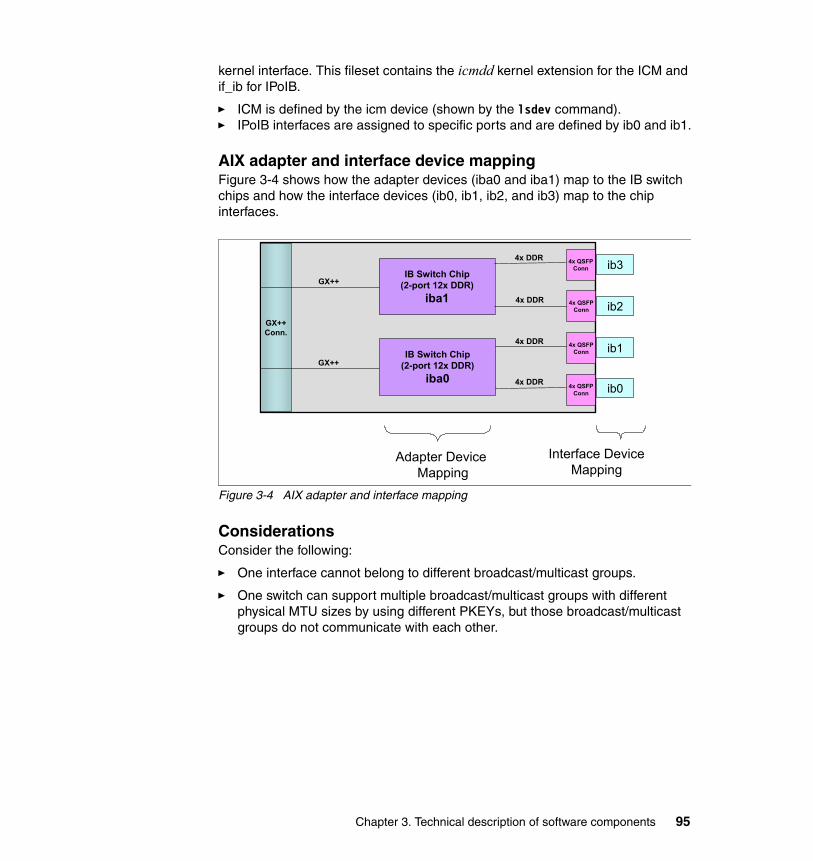
kernel interface. This fileset contains the icmdd kernel extension for the ICM and if_ib for IPoIB.
� ICM is defined by the icm device (shown by the lsdev command).� IPoIB interfaces are assigned to specific ports and are defined by ib0 and ib1.
AIX adapter and interface device mappingFigure 3-4 shows how the adapter devices (iba0 and iba1) map to the IB switch chips and how the interface devices (ib0, ib1, ib2, and ib3) map to the chip interfaces.
Figure 3-4 AIX adapter and interface mapping
ConsiderationsConsider the following:
� One interface cannot belong to different broadcast/multicast groups.
� One switch can support multiple broadcast/multicast groups with different physical MTU sizes by using different PKEYs, but those broadcast/multicast groups do not communicate with each other.
GX++Conn.
IB Switch Chip(2-port 12x DDR)
iba1
4x DDR
4x DDR
4x DDR
4x DDR
IB Switch Chip(2-port 12x DDR)
iba0
GX++
GX++
4x QSFPConn
4x QSFPConn
4x QSFPConn
4x QSFPConn
ib0
ib3
ib2
ib1
Adapter Device Mapping
Interface DeviceMapping
Chapter 3. Technical description of software components 95
� To create networks with 4 K MTU:
– The user is required to create a 4 K broadcast multicast group in the switch prior to configuring the interface.
– If no broadcast/multicast group is present, the interface creates one in the switch using a physical MTU of 2 K by default, even if the switch supports 4 K physical MTU.
� The super packet feature (64 k) is implemented in IPoIB on AIX only. Both ends of the communication must enable the super packet feature to operate properly.
3.1.4 InfiniBand software implementation on Linux
This section describes the InfiniBand software stack for Linux.
Open Fabrics Enterprise Distribution (OFED)OFED is a Linux-based software package that has been designed to exploit the InfiniBand infrastructure, as specified by the InfiniBand Trade Association (IBTA).
OFED has been developed by the OpenFabrics Alliance organization with the active participation of many host channel adapter (HCA) vendors, industry members, and national research laboratories. For a complete description of the OFED software stack, see the following Web page:
http://www.openfabrics.org/docs/Sep06_OpenFabrics_Stack.ppt
For more details, see also the OpenIB Wiki at:
http://openfabrics.org/tiki
The OFED stack consists of the following components:
� Core layer
This exposes APIs/IB verbs required to access InfiniBand-specific resources and functionality, for example, memory regions, queue pairs, MAD service, and so on. It implements the infrastructure for management of device drivers as well as HCA resources. In addition, the core layer is a vehicle for user and kernel communication.
� Driver layer
This consists of device drivers provided by the HCA provider. A device driver implements the kernel services as defined by IB verbs to allow consumers to access and manipulate the HCA’s resources. In the case of eHCA, it is hcad_mod and ib_ehca, respectively.
96 HPC Clusters Using InfiniBand on IBM Power Systems Servers
� Upper-level protocol layer
This composes kernel modules that rely on the core layer and provide another abstraction, for example, IP over InfiniBand or Socket Direct Protocol. This approach helps consumers to utilize InfiniBand based on the abstraction that they already know.
� User space library layer
This includes a set of libraries allowing user-level clients to access kernel services. Typically, a device driver provider also delivers an implementation of the IB user space API as a library. In the case of eHCA, it is libehca.
� Application layer
This includes all tools and applications that rely on IB user space API. Examples are the diagnostic tools such as ibstat, ibping, perfquery, and so on, located under the directory src/userspace/management/ or various implementations of the Message Passing Interface.
OFED IB and RDMA communication managersOpen fabrics provides two communication managers. The interfaces for both CMs are defined in their respective header files:
� IB CM
The IB CM is the low-level InfiniBand communication manager. It is based on the InfiniBand connection state machine as defined by the IB architecture spec and handles both connection establishment and service ID resolution. Use of the IB CM requires knowledge the IB CM protocols defined in Chapter 12 of the IB Architecture Spec Release 1.2 APIs:
– kernel: include/rdma/ib_cm.h– userspace: libibcm/include/infiniband/cm.h
� RDMA CM
The RDMA CM, also referred to as the communication manager abstraction (CMA) is a higher-level CM that operates based on IP addresses. The RDMA CM provides an interface that is closer to that defined for sockets and is transport independent, allowing users access to multiple RDMA devices, such as IB HCAs and iWarp2 RDMA-enabled NICs (RNICs). For most developers, the RDMA CM provides a simpler interface sufficient for most applications.
The RDMA CM supports reliable connected, unreliable datagram, and multicast communication. Functionality is provided through the following application programming interfaces (APIs):
– kernel: include/rdma/rdma_cm.h– userspace: librdmacm/include/rdma/rdma_cma.h
2 http://www.neteffect.com/documents/understanding_iwarp.pdf
Chapter 3. Technical description of software components 97
IPoIBThe IPoIB project implements this proposed standard as a layer-2 Linux network driver. The primary responsibilities of the driver are performing address resolution to map IPv4 and IPv6 addresses to InfiniBand UD address vectors, the management of multicast membership, and the transmission and reception of IPoIB protocol frames. For more information about IPoIB see the following URL:
http://infiniband.sourceforge.net/NW/IPoIB/index.htm
Linux HCAD device driverThis section covers the current capabilities of HCA1 and 2.
eHCA capabilitiesThe Linux eHCA V1 driver became generally available in 2006 with the following capabilities:
� 2 k MTU
� Low-latency RC queues (user data in work request)
Originally, it was used for IBM System p570 for PCIe expansion network, 12x SDR mode.
The eHCA V2 drive has the following capabilities:
� 4 k MTU� Low-latency UD/RC queues� Shared receive queue� System p Linux drivers available in OFED-1.3
98 HPC Clusters Using InfiniBand on IBM Power Systems Servers
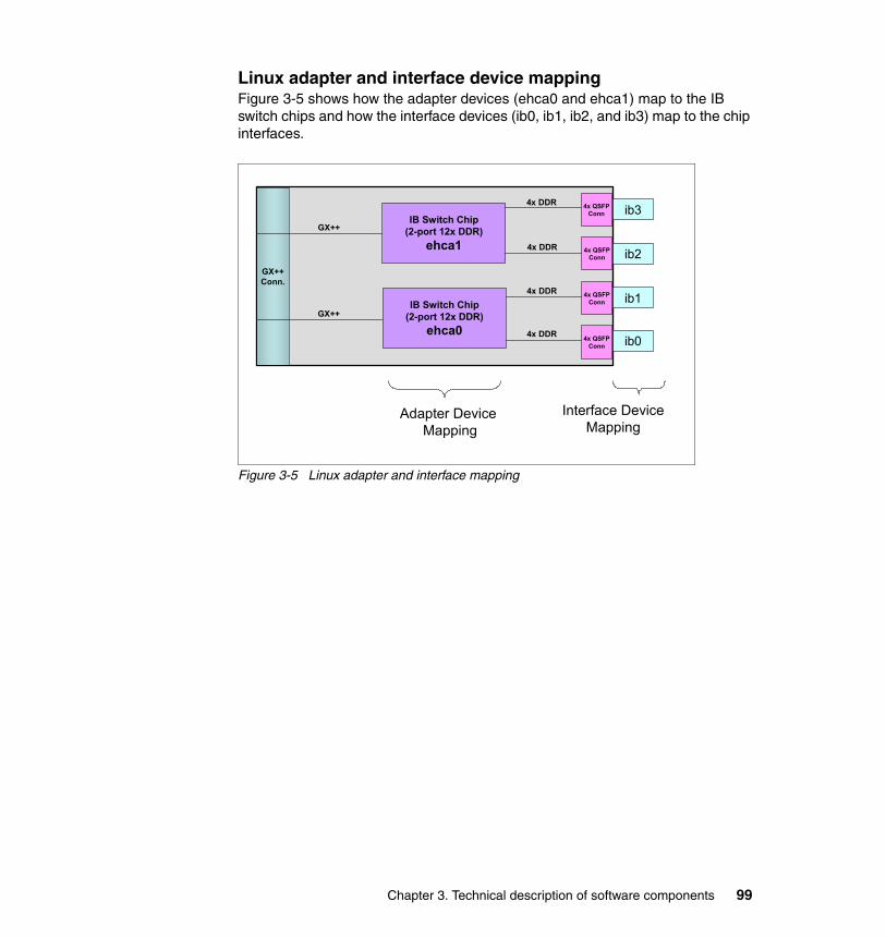
Linux adapter and interface device mappingFigure 3-5 shows how the adapter devices (ehca0 and ehca1) map to the IB switch chips and how the interface devices (ib0, ib1, ib2, and ib3) map to the chip interfaces.
Figure 3-5 Linux adapter and interface mapping
GX++Conn.
IB Switch Chip(2-port 12x DDR)
ehca1
4x DDR
4x DDR
4x DDR
4x DDR
IB Switch Chip(2-port 12x DDR)
ehca0
GX++
GX++
4x QSFPConn
4x QSFPConn
4x QSFPConn
4x QSFPConn
ib0
ib3
ib2
ib1
Adapter Device Mapping
Interface DeviceMapping
Chapter 3. Technical description of software components 99
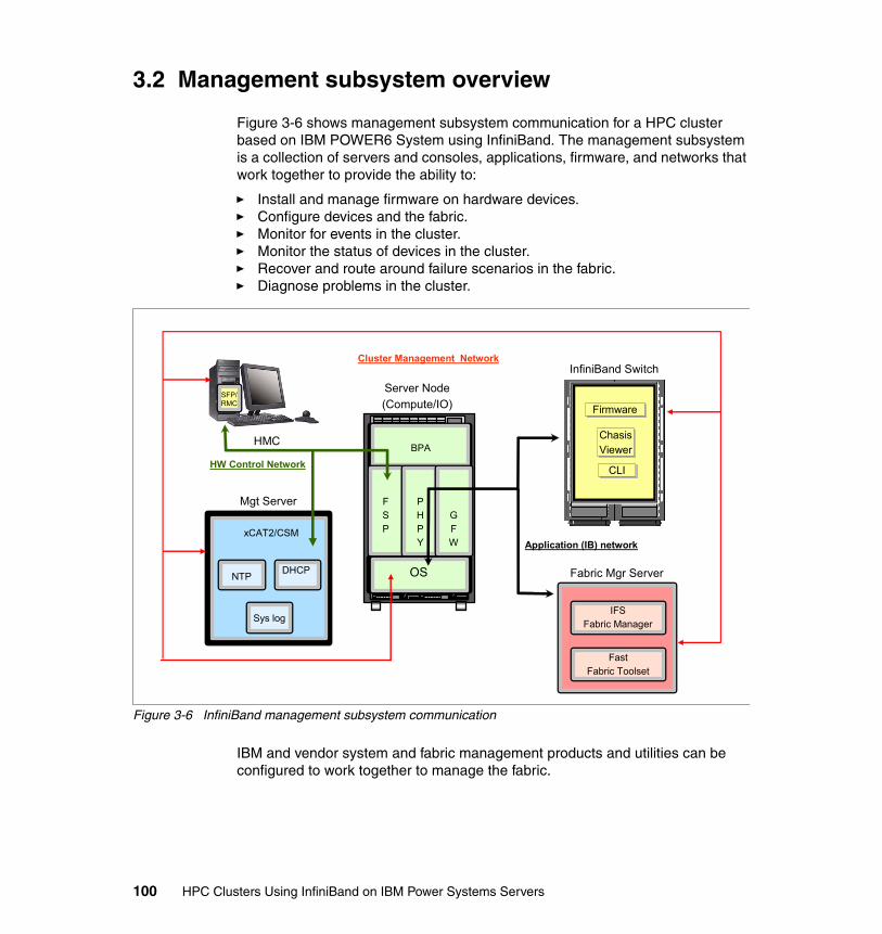
3.2 Management subsystem overview
Figure 3-6 shows management subsystem communication for a HPC cluster based on IBM POWER6 System using InfiniBand. The management subsystem is a collection of servers and consoles, applications, firmware, and networks that work together to provide the ability to:
� Install and manage firmware on hardware devices.� Configure devices and the fabric.� Monitor for events in the cluster.� Monitor the status of devices in the cluster.� Recover and route around failure scenarios in the fabric.� Diagnose problems in the cluster.
Figure 3-6 InfiniBand management subsystem communication
IBM and vendor system and fabric management products and utilities can be configured to work together to manage the fabric.
InfiniBand Switch
IB Switch
IB Switch
IB Switch
IB Switch
IB Switch
IB Switch
IB Switch
IB Switch
CLICLI
ChasisViewerChasisViewer
Mgt Server
xCAT2/CSM
NTP DHCP
Sys log
HMC
SFP/RMC
Server Node(Compute/IO)
OS
BPA
FSP
PHPY
GFW
Fabric Mgr Server
IFSFabric Manager
FastFabric Toolset
Application (IB) network
Cluster Management Network
HW Control Network
FirmwareFirmware
100 HPC Clusters Using InfiniBand on IBM Power Systems Servers
3.2.1 Network definitions
The primary intra-cluster network used to provide high bandwidth and low latency is, of course, InfiniBand. Clusters also require additional networks besides InfiniBand. These networks are used for cluster management, software maintenance, and user access and are, in general, separate Ethernet networks.
Typically, the networks will also connect key servers to a local network to provide remote access for managing the cluster. The most common networks are discussed in the following sections.
Cluster management networkThis network provides cluster management communication. It is used to provide connectivity between the following cluster components:
� Server node (compute, I/O nodes)
This provides management (generally through xCAT2 or CSM) and installation connectivity to the chosen operating system of the cluster compute nodes. This includes access to any storage nodes (I/O) that might exist (for example, GPFS NSD).
� Management node
This provides a transport for the installation of the nodes as well as management of various cluster components using the xCAT2-provided utilities. It is also utilized as the transport for the central repository of various logs (for example, syslog from compute nodes and InfiniBand switches).
� QLogic Fabric Manager Server
This is used to log in and perform management functions on the QLogic Fabric Manager either directly to the hosts or via xCAT2.
� InfiniBand switches
This is used to log in and perform management functions on the InfiniBand switches, either directly on the switches or via xCAT2.
� Hardware Management Console
This provides systems administrators a tool for planning, deploying, and managing IBM Power System servers.
Chapter 3. Technical description of software components 101
Hardware control networkThis network is used to provide a management of hardware components in the cluster. It should be kept separate from any other network. The hardware components connected to this network are:
� Hardware Management Consoles
The HMC uses a Ethernet connection (a private LAN) to connect to the attached System p machine’s flexible service processor (FSP). The FSP stores all the information about logical partitions (LPARs), capacity on demand (CoD), and other configuration information.
� Bulk power hub (BPH)
This provides network connectivity between Ethernet-connected components of the bulk power assembly (BPA) and the IBM Power 575 Flexible Service Processors (FSPs). A dedicated port is provided to allow connectivity to the private network for these components.
� Flexible service processors
The FSP allows access to the Advanced System Management Interface (ASMI) for each central electronic complex (CEC), as well as allow the HMC to control various functions of the CEC.
� Dynamic Host Configuration Protocol (DHCP) server
A DHCP server must be implemented to provide IP addresses to the various components of the BPA and the FSPs for the IBM Power 575s. The location of the DHCP server is not critical. However, we recommend that you install and configure it on a component that is most likely to be available at all times. Because of this, the HMC is usually not used for this role.
Generally, this is implemented with xCAT2 (using a separately configured DHCP server provided with the management server OS) or the CSM (through Cluster Ready Hardware Server (CRHS)) management server. With all options other than CRHS on CSM, the FSPs must be added to the HMC or xCAT2 management node (MN) that will manage that component manually, using the procedure outlined in the HMC documentation.
Application (IB) networkThis network provides node-to-node cluster application communication. This network is completely enclosed inside the cluster and generally there is no user access to this network.
Public networkThis network (not shown in Figure 3-6 on page 100) provides user access to the cluster. Generally, in HPC environments, this network is separated from all other
102 HPC Clusters Using InfiniBand on IBM Power Systems Servers
cluster networks (for security reasons) and access to cluster resources is achieved via dedicated nodes (that is, front-end nodes).
3.2.2 Fabric Management Server
For QLogic InfiniBand Fabric Suite software package platform support, see the following URL and follow the IBM System p InfiniBand Switches & Management Software - HPC link on this page.
http://driverdownloads.qlogic.com/QLogicDriverDownloads_UI/IBM.aspx?companyid=6
InfiniBand Fabric Suite The QLogic InfiniBand Fabric Suite bundles the installation of the Fabric Manager and FastFabric Toolset to provide an integrated fabric management solution. For large fabrics, this software is installed on a Linux server host called Fabric Management Server. IBM Power Systems clusters require the use of the host-based Fabric Manager (standalone x86_64 server).
In Linux installations, an enhanced version of the Open Fabric Alliance InfiniBand stack protocols can be installed through the IFS. The Open Fabric Enterprise Distribution is an InfiniBand architecture and open software stack that is interoperable across multiple vendors. The IFS described in this book is based on the OFED 1.3 version. More information regarding OFED and the Open Fabric Alliance can be found at:
http://www.openfabrics.org
Terminology note: It should be noted that any reference to the InfiniBand Fabric Suite (IFS), the Fabric Manager and its components, or the FastFabric Toolset are QLogic software products. It will be noted otherwise if this does not apply. The QLogic products mentioned in this section are:
� QLogic InfiniBand Fabric Suite� QLogic Fabric Manager and its components:
– QLogic subnet manager – QLogic performance manager– QLogic baseboard manager – QLogic Fabric Executive
� QLogic FastFabric Toolset� QLogic Fabric Viewer
Chapter 3. Technical description of software components 103
QLogic InfiniBand Fabric ManagerThe Fabric Manager (FM) provides HPC environments with a number of benefits including fast configuration and reconfiguration time, extensive switch and fabric management capabilities from the command line and the graphical user interface, and key components with automatic failover capabilities.
The FM comprises several components:
� Subnet manager� Performance manager� Baseboard manager � Fabric executive
Subnet managerThe subnet manager is responsible for configuring the switches and control of the subnet. Each fabric (also called planes, instances, or subnets) must have at least one master subnet manager to configure and control the fabric. An additional subnet manager can be started in the fabric to act as a standby for redundancy. In the implementation of the fabric by IBM Power Systems, the subnets are distinct entities. Up to four subnets can be managed by the Fabric Manager from a single Linux server host.
The SM on each fabric works with the subnet management agent that is present on each node and switch. Because the fabric is IBTA compliant, the subnet management agents can be developed by IBM or other entities for AIX and will still interoperate with the FM as long as they are also IBTA compliant. IBTA is the InfiniBand Trade Association that architects the InfiniBand solutions.
The SM:
� Discovers the fabric topology (commonly called a sweep).
� Configures the node channel adapters with the local addresses for each physical port (the LID), sets the subnet prefix, and other information required for the fabric.
� Configures the switches with the local addresses for each physical port (the LID), sets the subnet prefix, and other information required for the fabric.
� Configures the channel adapter with local addresses for each physical port and other information required for the fabric on the adapter on the host where the QLogic subnet manager is running.
� Configures the routing tables in the switches on startup and when nodes join or leave the fabric.
� Re-routes packets around failed links by reloading the switch tables where multiple paths through the switches exist for redundancy.
104 HPC Clusters Using InfiniBand on IBM Power Systems Servers
� Provides fabric administration through the subnet administration service. This service allows nodes to access information about the subnet and to resolve paths and register their services.
� Maintains the node and service databases for resolution services and services directory.
Along with the subnet management agent (SMA) on each switch and node, other service agents are also present. These are:
� Performance manager agent
The QLogic Performance Manager (PM) works with the PM agents (PMAs) to monitor and report port counter values as well as transmit and receive values for data and packets for each port in the fabric. This includes the internal switch link (ISL) ports on the SilverStorm 9000 Series Switch.
� Baseboard Management agent
The QLogic Baseboard Manager (BM) works with the BM agents (BMAs) to provide in-band (over the InfiniBand subnet) hardware management. Examples of this management include retrieval of vital product data like serial number and manufacturing information and retrieval of environmental data such as temperature and voltage senor readings. In an IBM Power Systems cluster, retrieval of this type of information is limited to the switches.
� Fabric Executive application
The QLogic Fabric Executive (FE) provides for Ethernet access outside of the IB fabric (out of band) to the IFS. The FE listens on a private TCP/IP socket for communication from the QLogic Fabric Viewer and then uses the IB fabric to communicate with other managers to gather information or perform management tasks.
For more information consult the QLogic Fabric Manager Users Guide, D000007-002 Rev A, available from the InfiniBand Switches and Management Software for IBM System p Clusters Web site at:
http://support.qlogic.com/support/oem_ibm.asp
QLogic InfiniBand Fabric Suite FastFabric ToolsetThe QLogic InfiniBand Fabric Suite FastFabric Toolset (FFT) is a comprehensive, powerful set of tools for quickly installing and managing a large fabric. The software offers a textual user interface (TUI) menu for easy installation and command-line tools for your scripting needs.
With the FFT, you can administer your switches, configure and re-configure your fabrics, verify your installation, and monitor your fabrics with port counters and
Chapter 3. Technical description of software components 105

automated fabric, chassis and Fabric Manager health checks, and establish configuration baselines.
The QLogic FastFabric Toolset also contains commands that help you to verify that your fabric is set up correctly and manage and troubleshoot your subnets. For an overview of the commands refer to Chapter 9, “Fabric management and monitoring” on page 283.
For more information regarding all of the above commands, consult the QLogic Fast Fabric Users Guide, D000006-033 Rev B, available from the InfiniBand Switches and Management Software for IBM System p Clusters Web site at:
http://support.qlogic.com/support/oem_ibm.asp
QLogic InfiniBand Fabric Suite Fabric ViewerThe QLogic InfiniBand Fabric Suite Fabric Viewer (FV) is a separate package that contains the Java™-based graphical user interface (GUI). The FV communicates with the FE installed as part of the FM and allows you to perform a subset of management tasks and gives you a topology or hierarchical fabric view. The FV is typically used with small clusters.
The key features include the topology and hierarchical views of the fabric, component status displayed as symbols, user-configurable events, performance graphics for nodes and ports, and management support.
For more information about the QLogic Fabric Viewer consult the QuickSilver Fabric Manager and Fabric Viewer Users Guide, D000007-001 Rev A, available from the InfiniBand Switches and Management Software for IBM System p Clusters Web site at
http://support.qlogic.com/support/oem_ibm.asp
3.2.3 IBM InfiniBand 7874 switch series
For IBM machine type (M/T) to QLogic model correspondence, see Table 2-8 on page 77.
SilverStorm 9000 Series Switch firmware by QLogicThe SilverStorm 9000 Series Switch firmware by QLogic resides in the managed spines on the director switches and in the chassis management unit (CMU) of the smaller switch. This firmware contains an internal switch-based performance management agent, baseboard management agent, and the subnet management agent described under the QLogic Fabric Manager, although these agents are not directly viewable. Some tables, such as the linear forwarding table
106 HPC Clusters Using InfiniBand on IBM Power Systems Servers

configured by the QLogic subnet manager, can be viewed using specific commands.
The firmware also allows you to configure and manage the switch and upgrade the switch firmware on a per-switch basis.
All management and debug activities are available from the CLI, and a subset of those activities are available from the GUI called the Qlogic SilverStorm 9000 Chassis Viewer.
Qlogic SilverStorm 9000 Chassis ViewerThe home page provides a high-level overview of the switch displaying a representation of the front and back of the switch. From here you can see the number of leafs and spines in your switch as well as which ports have cables connected and which spine is the master.
You can then click a leaf for leaf-specific information, click a spine for spine-specific information, or click the chassis for chassis information including fans, power supplies, or the switch backplane.
From the chassis panel, you can set up logging, Simple Network Management Protocol (SMNP), view the port statistics for the entire switch, and upgrade the firmware.
From a leaf panel, you can view information about the leaf and see the port statistics for that leaf only.
From the spine panel, you can view information about the spine, see the spine port statistics, select the boot image, and work with license keys.
In smaller clusters, a switch based QLogic Fabric Manager can be configured instead of using a separate host. This requires a separate license to enable this feature. A switch based QLogic Fabric Manager and a host based QLogic Fabric Manager should not be running in the same cluster.
Qlogic SilverStorm 9000 series command-line interfaceThe CLI groups commands by function for administrator ease in finding particular commands. These groups are:
� General� Deprecated� Chassis� Network� Firmware� Log� IbSwitchInfo
Chapter 3. Technical description of software components 107
� TimeManagement� SNMP� Capture
Two others, SubnetManagement and KeyManagement, are only used for switch based QLogic Fabric Manager .
When working with the SilverStorm 9240 switch, there is an upper hemisphere and a lower hemisphere. Commands must be run in both hemispheres to properly configure the switch even if one of the hemispheres is not populated with leafs. The reason is that all leafs in both hemispheres are connected to the same backplane. Only data returned for the hemisphere in which the command is run is valid. To obtain a total view of the switches on the SilverStorm 9240, you must run the command in both hemispheres.
Logging on to the switch and using the CLI commands is a typical debug action on a per-switch basis.
For more information regarding the SilverStorm 9000 Series Switch commands and Chassis Viewer consult the Silver Storm 9000 Users Guide, D000003-016 Rev A, and the Silver Storm 9000 CLI Reference Guide, D000025-001 Rev A, available from the InfiniBand Switches and Management Software for IBM System p Clusters Web site at:
http://support.qlogic.com/support/oem_ibm.asp
3.2.4 Nodes (compute, I/O)
The compute nodes are used to carry out the computational workload. The I/O nodes are used to provide persistent storage access for the compute nodes.
Operating systemThe operating system is the interface for the device drivers. On AIX, device drivers and upper-layer software is provided by IBM. On Linux, the IB software stack is the Open Fabrics Enterprise Distribution.
FirmwareA description of the firmware for the FSP, POWER Hypervisor (PHyp), global firmware (GFW), BPA, and BPH can be found in 2.2, “POWER6 Systems” on page 44.
108 HPC Clusters Using InfiniBand on IBM Power Systems Servers
3.2.5 Cluster management node (server)
The management server or management node is used by the system administrators to monitor and manage the cluster. The two products currently supported are Extreme Cluster Administration Tool Version 2 (xCAT2) and IBM Cluster Systems Management (CSM).
xCAT2 xCAT 2 is a complete rewrite of xCAT 1.3 that includes many architectural changes and functional enhancements. All commands are client/server, authenticated, logged, and policy driven. XCAT2 supports roll base authentication. The clients can be run on any OS with Perl, including Windows®. All communication is SSL encrypted. The code has been completely rewritten in Perl, and table data is now stored in a relational database and with the plug-in architecture you can chose your database from SQLite, MySQL, and PostgreSQL with more options coming.
In the xCAT client/server application, flow between the client and the server is controlled by the xCAT daemon (xcatd) on the management node. When xcatd receives the command that has been packaged as XML, it determines whether the sender has authority to execute the command by evaluating the access control lists (ACLs) in the policy table. The daemon also receives status and inventory information from the nodes as they are deployed.
For details and examples about how to implement xCAT clusters, also see the following publications:
� xCAT 2 Guide for the CSM System Administrator, REDP-4437� Configuring and Managing AIX Clusters Using xCAT 2, SG24-7766
For more xCAT code and official documentation see:
http://www.xcat.org
Cluster Systems Manager CSM (with the infrastructure provided by Reliable Scalable Cluster Technology (RSCT) provides a consistent interface for managing both AIX and SUSE Linux Enterprise Server (SLES) nodes and also has the flexibility to manage across multiple hardware platforms, various network topologies, and different geographic sites.
CSM is designed to scale up to a large number of servers and to protect performance by providing very efficient monitoring and reduced network traffic. Automatic error detection is another key feature of CSM that can help with problem avoidance, rapid resolution, and recovery.
Chapter 3. Technical description of software components 109
CSM software provides a distributed system management solution that allows a system administrator to set up and maintain a cluster of nodes that run the AIX or SLES operating system. CSM simplifies cluster administration tasks by providing management from a single point-of-control.
For CSM documentation and more, see the following URL:
http://publib.boulder.ibm.com/infocenter/clresctr/vxrx/index.jsp?topic=/com.ibm.cluster.csm.doc/clusterbooks.html
3.2.6 Hardware Management Console
The IBM Hardware Management Console provides systems administrators with a tool for planning, deploying, and managing IBM System p servers. The major functions that the HMC provides are server hardware management and virtualization (partition) management.
For more information about the HMC, refer to the following Web page:
http://publib.boulder.ibm.com/infocenter/eserver/v1r3s/index.jsp?topic=/ipha1/hardwaremanagementconsolehmc.htm
3.3 HPC IB stack overview
In recent years, high performance computing has become popular in many industries. HPC has the capabilities to deliver the performance needed for the computing jobs used for mathematical simulation of complex natural phenomena. With the profit of clustering technology and the growing acceptance of open source software, supercomputers can now be created for a fraction of the cost of traditional high-performance machines.
In the early times of cluster-based computing, the typical supercomputer was a solution based on vector processors, which was usually much more expensive due to specialized hardware and software. With AIX, SLES 11 and other open source clustering software components, and technological advances in commodity hardware, the situation now is quite different.
You can now build powerful clusters with a relatively small budget and keep adding extra nodes based on computing needs. Almost every industry requires fast processing power. With the increasing availability of cheaper and faster computers, more and more companies are interested in exploiting the technological benefits. There is no upper boundary to the needs of computer processing power, even with the rapid increase in power. The demand is considerably more than what is currently available.
110 HPC Clusters Using InfiniBand on IBM Power Systems Servers
3.3.1 HPC infrastructure management software
The IBM cluster system management software stack is a set of software tools that provides the ability to make the cluster system management easier. Extreme Cluster Administration Tool 2 or Cluster System Management provide the ability to manage your cluster from a single point of control for installing, monitoring, and maintaining your cluster. See also 3.2.5, “Cluster management node (server)” on page 109.
IBM Tivoli Workload Scheduler LoadLeveler is a parallel job-scheduling system that allows users to run more jobs in less time by matching each job's processing needs and priority with the available resources, thereby maximizing resource utilization.
Reliable Scalable Clustering Technology (RSCT)3 is the infrastructure used by a variety of IBM products to provide clusters with improved system availability, scalability, and ease of use.
We describe the software packages, focusing on the enhancement for using InfiniBand, in following sections. For more information about these software packages, visit the IBM Cluster Information Center at:
http://publib.boulder.ibm.com/infocenter/clresctr/vxrx/index.jsp
IBM Tivoli Workload Scheduler LoadLevelerIBM Tivoli Workload Scheduler LoadLeveler is a parallel job-scheduling system that allows users to run more jobs in less time by matching each job's processing needs and priority with the available resources, thereby maximizing resource utilization. LoadLeveler also provides a single point of control for effective workload management, offers detailed accounting of system utilization for tracking or chargeback and supports high-availability configurations.
When jobs are submitted to LoadLeveler, they are not necessarily executed in the order of submission. Instead, LoadLeveler dispatches jobs based on their priority, resource requirements, and special instructions. For example, administrators can specify that long-running jobs run only on off-hours, that short-running jobs be scheduled around long-running jobs, or that certain users or groups get priority. In addition, the resources themselves can be tightly controlled. Use of individual machines can be limited to specific times, users, or job classes, or LoadLeveler can use machines only when the keyboard and mouse are inactive.
LoadLeveler tracks the total resources used by each serial or parallel job and offers several reporting options to track jobs and utilization by user, group,
3 The IBM state-of-art resource management and monitoring infrastructure for AIX and Linux
Chapter 3. Technical description of software components 111
account, or type over a specified time period. To support chargeback for resource use, LoadLeveler can incorporate machine speed to adjust chargeback rates and be configured to require an account for each job. LoadLeveler offers both a CLI and a GUI in addition to an API enabling user-written applications to control it.
LoadLeveler also supports high-availability configurations to ensure reliable operation and automatically monitors the available compute resources to ensure that no jobs are scheduled to failed machines.
Advanced LoadLeveler capabilities and featuresThe capabilities and features of the advanced LoadLeveler are:
� Easily scalable to thousands of processing nodes and thousands of parallel jobs in the job queue, LoadLeveler is an industrial-strength product that has been available on parallel computing platforms for 15 years.
� LoadLeveler incorporates the latest technologies in parallel batch scheduling research. An early adopter of the backfill scheduling algorithm, IBM has continued to improve the speed, scalability, and performance of this algorithm in LoadLeveler.
� The first batch scheduler to offer a complete scheduling API, LoadLeveler currently offers unprecedented flexibility with a complete array of APIs, allowing a high level of site-specific customization.
� LoadLeveler is a completely distributed program with extensive failover and self-repair capabilities to survive even severe system events, usually without administrator intervention.
� LoadLeveler offers job checkpointing and suspension with optional job cancellation, hold, and re-queue). These capabilities provide great flexibility in defining real-time job and resource priority control.
� LoadLeveler integrates with AIX Workload Manager (WLM) to provide both resource specification on job start and resource utilization controls to prevent resource overuse by errant applications.
General Parallel File System (GPFS)IBM General Parallel File System provides file system services to parallel and serial applications running on multiple nodes. GPFS allows parallel applications simultaneous access to the same files, or different files, from any node that has the GPFS file system mounted while managing a high level of control over all file system operations. GPFS is particularly appropriate in an environment where the aggregate peak need for data bandwidth exceeds the capability of a distributed file system server.
112 HPC Clusters Using InfiniBand on IBM Power Systems Servers

GPFS allows users shared file access within a single GPFS cluster and across multiple GPFS clusters. A GPFS cluster consists of:
� AIX 6.1 nodes, Linux nodes, or a combination of AIX 6.1 and Linux nodes. A node may be:
– An individual operating system image on a single computer within a cluster.
– A partition (LPAR) running an individual copy of an operating system (AIX of Linux). Some System p machines allow multiple system partitions, each of which is considered to be a node within the GPFS cluster.
� Network shared disks (NSDs) created and maintained by the NSD component of GPFS.
– All disks utilized by GPFS must first be given a globally accessible NSD name.
– The GPFS NSD component provides a method for cluster-wide disk naming and access.
On Linux machines running GPFS, you may give an NSD name to:
• Physical disks • Logical partitions of a disk • Representations of physical disks (such as LUNs)
On AIX machines running GPFS, you may give an NSD name to:
• Physical disks • Virtual shared disks • Representations of physical disks (such as LUNs)
� A shared network for GPFS communications allowing a single network view of the configuration. A single network, a LAN, or a switch is used for GPFS communication, including the NSD communication.
Basic GPFS componentsGPFS is a clustered file system defined over a number of nodes. On each node in the cluster, GPFS consists of:
� Administration commands
Most GPFS administration tasks can be performed from any node running GPFS.
� A kernel extension (file system device driver)
The GPFS kernel extension provides the interfaces to the operating system virtual node (vnode) and virtual file system (VFS) interfaces for adding a file system.
Chapter 3. Technical description of software components 113
� A multithreaded daemon
The GPFS daemon performs all I/O and buffer management for GPFS.
� For nodes in your cluster operating with the Linux operating system and the GPFS open source portability layer
For Linux nodes running GPFS, you must build custom portability modules based on your particular hardware platform and Linux distribution to enable communication between the Linux kernel and the GPFS kernel modules.
GPFS and network communicationWithin the GPFS cluster, you may specify different networks for GPFS daemon communication and for GPFS administration command usage. The default communications protocol for communication between nodes in a GPFS cluster is TCP/IP. This is the only currently supported communication protocol in a GPFS cluster environment.
The interconnect for GPFS daemon-to-daemon and administration command communication depends upon the types of nodes in your cluster. The latest supported interconnects and environments can be found at:
http://publib.boulder.ibm.com/infocenter/clresctr/vxrx/topic/com.ibm.cluster.gpfs.doc/gpfs_faqs/gpfsclustersfaq.pdf
GPFS and InfiniBandAccording to the previously mentioned Web site, currently (at the time of this writing and for the current GPFS version) InfiniBand is supported for GPFS interconnect in an HPC environment using IP over InfiniBand.
Further information about GPFS can be found at:
http://publib.boulder.ibm.com/infocenter/clresctr/vxrx/index.jsp?topic=/com.ibm.cluster.gpfs.doc/gpfsbooks.html
3.3.2 HPC application software
As mentioned in the beginning of this chapter, MPI is one of the most used methods for parallel computing. IBM Parallel Environment provides optimized compatible communication functions, a library, and a runtime environment for MPI applications. To perform data communication and for optimal performance, PE interfaces with LAPI.
LAPI is a message-passing API that provides a one-sided communication model. LAPI interfaces with a lower-level protocol, running in the user space (user space protocol), which offers a low-latency and high-bandwidth communication path to user applications, running over a high-performance switched networking
114 HPC Clusters Using InfiniBand on IBM Power Systems Servers

infrastructure. Alternatively, LAPI also interfaces with the IP layer. Programers can use LAPI with or without the parallel operating environment (POE). POE is a component of the IBM Parallel Environment licensed program.
IBM Parallel Environment The IBM Parallel Environment program product is an environment designed for developing and executing parallel Fortran, C, or C++ programs. PE consists of components and tools for developing, executing, debugging, profiling, and tuning parallel programs.
PE is a distributed memory message-passing system. You can use PE to execute parallel programs on a variety of hardware, using the AIX or Linux operating system.
The processors of your system are called processor nodes. If you are using a Symmetric Multiprocessor (SMP) system, it is important to know that, although an SMP node has more than one processing unit, it is still considered, and referred to as, a processor node.
A parallel program executes as a number of individual, but related, parallel tasks on a number of your system's processor nodes. These parallel tasks taken together are sometimes referred to as a parallel job. The group of parallel tasks is called a partition. The processor nodes are connected on the same network, so the parallel tasks of your partition can communicate to exchange data or synchronize execution:
� Your system may have an optional high-performance switch for communication. The switch increases the speed of communication between nodes. It supports a high volume of message passing with increased bandwidth and low latency.
� Your system may use the InfiniBand host channel adapter for improved I/O performance. PE only supports the InfiniBand host channel adapter on specific hardware. For more information refer to IBM Parallel Environment: Installation. Parallel Environment Publications can be found at:
http://publib.boulder.ibm.com/infocenter/clresctr/vxrx/index.jsp?topic=/com.ibm.cluster.pe.doc/pebooks.html
� Your system administrator can divide its nodes into separate pools. A LoadLeveler system pool is a subset of processor nodes and is given an identifying pool name or number.
PE supports the two basic parallel programming models:
� Single program multiple data (SPMD) � Multiple program multiple data (MPMD)
Chapter 3. Technical description of software components 115

In the SPMD model, the same program is running as in each parallel task of your partition. The tasks, however, work on different sets of data. In the MPMD model, each task may be running a different program. A typical example of this is the master/worker MPMD program. In a master/worker program, one task (the master) coordinates the execution of all the others (the workers).
Application's entire life cyclePE consists of the following components:
� A message passing library (MPI), for communication among the tasks that make up a parallel program. The application developer begins by creating a parallel program's source code. The application developer might create this program from scratch or could modify an existing serial program. In either case, the developer places calls to MPI or LAPI routines so that it can run as a number of parallel tasks.
� After writing the parallel program, the application developer then begins a cycle of modification and testing. The application developer now compiles and runs his program from his home node using the POE. The home node can be any workstation on the LAN that has PE installed. POE is an execution environment designed to hide, or at least smooth, the differences between serial and parallel execution.
� To assist with node allocation for job management, IBM Tivoli Workload Scheduler (TWS) LoadLeveler provides resource management function. AIX users can run parallel programs on a cluster of processor nodes running LoadLeveler or a clustered server that uses LoadLeveler.
� In general, with POE, you invoke a parallel program from your home node and run its parallel tasks on a number of remote nodes. As much as possible, the remote nodes should be managed to ensure that when they are running the tasks of your parallel program, none of them are being used for other activities. When you invoke a program on your home node, POE starts your partition manager, which allocates the nodes of your partition and initializes the local environment.
� POE provides an option to enable you to specify whether your program will use MPI, LAPI, or both. Using this option, POE ensures that each API initializes properly and informs LoadLeveler of which APIs are used so that each node is set up completely.
� For SPMD applications the partition manager executes the same program on all nodes. For MPMD applications, the partition manager prompts you for the name of the program to load as each task. The partition manager also connects standard I/O to each remote node so that the parallel tasks can communicate with the home node. Although you are running tasks on remote nodes, POE allows you to continue using the standard UNIX, AIX, or Linux execution techniques with which you are already familiar.
116 HPC Clusters Using InfiniBand on IBM Power Systems Servers
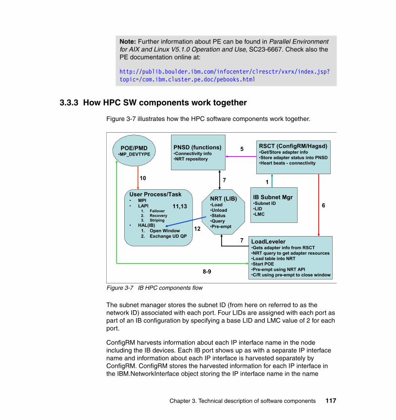
3.3.3 How HPC SW components work together
Figure 3-7 illustrates how the HPC software components work together.
Figure 3-7 IB HPC components flow
The subnet manager stores the subnet ID (from here on referred to as the network ID) associated with each port. Four LIDs are assigned with each port as part of an IB configuration by specifying a base LID and LMC value of 2 for each port.
ConfigRM harvests information about each IP interface name in the node including the IB devices. Each IB port shows up as with a separate IP interface name and information about each IP interface is harvested separately by ConfigRM. ConfigRM stores the harvested information for each IP interface in the IBM.NetworkInterface object storing the IP interface name in the name
Note: Further information about PE can be found in Parallel Environment for AIX and Linux V5.1.0 Operation and Use, SC23-6667. Check also the PE documentation online at:
http://publib.boulder.ibm.com/infocenter/clresctr/vxrx/index.jsp?topic=/com.ibm.cluster.pe.doc/pebooks.html
POE/PMD•MP_DEVTYPE
NRT (LIB)•Load•Unload•Status•Query•Pre-empt
LoadLeveler•Gets adapter info from RSCT•NRT query to get adapter resources•Load table into NRT•Start POE•Pre-empt using NRT API•C/R using pre-empt to close window
PNSD (functions)•Connectivity info•NRT repository
RSCT (ConfigRM/Hagsd)•Get/Store adapter info•Store adapter status into PNSD•Heart beats - connectivity
IB Subnet Mgr•Subnet ID•LID•LMC
User Process/Task• MPI• LAPI
1. Failover2. Recovery3. Striping
• HAL(IB)1. Open Window 2. Exchange UD QP
11,13
7
6
17
5
8-9
12
10
Chapter 3. Technical description of software components 117

attribute within the object. Among the harvested information, ConfigRM should obtain the base LID, LMC, and base GID for each port (IP interface). The network ID is the top 64-bits of the base GID and is an additional attribute that will be gleaned by ConfigRM.
ConfigRM will map the IP interface to a specific device name for use in ensuing user space IB verbs calls. These device names will be of the form hcaX for host channel adapters, where X is 0, 1, 2, and so on. The retrieved physical device name will be stored in the DeviceName attribute of IBM.NetworkInterface. Multiple IP interfaces may have the same DeviceName.
High Availability Topology Services (HATS) and High Availability Group Services (HAGS) begin execution, and information harvested by ConfigRM is circulated so that the Network Availability Matrix (NAM) on each node can be populated (by obtaining information through the RSCT NAM API).
Protocol Network Services Daemon (PNSD) on each node obtains information for each connection.
� Before 11/08, this was done via the RSCT NAM API and populates the NAM. This information includes node ID, IP address, physical device name, base LID, LMC, network ID, and base GID for each connection.
� After 11/08, PNSD removed dependency on RSCT. To gather local adapter information, in AIX the ibstat command is used, and in Linux ibv_devinfo is used.
LoadLeveler generates the configuration file using the llextRPD command, which queries the IBM.NetworkInterface object and generates a stanza for each IP interface, which is each IB port in our case. For each IP interface, LL will use the DeviceName to make an NRT API call to query adapter resources for the corresponding device. Ideally, LL can decipher that several of the IP interfaces correspond to a single device and make the NRT API query once, but making the call repeatedly should result in the same values being returned and cause no harm. In the latter case, LL must realize that the data returned represents resources across all of the ports of one device.
The NRT API calls will be implemented by opening a connection to the PNSD and, depending on the call, passing over specific commands to the PNSD requesting corresponding action. The virtual window resources will be implemented in and managed by the PNSD. For the query adapter resources call, the PNSD will return a list of virtual window resources that have not yet been assigned to LL (that is, a list of windows for which LL has not loaded an NRT). It will also query the NAM and return the base LID for each of the underlying ports of the adapter as well as the corresponding LMC values.
118 HPC Clusters Using InfiniBand on IBM Power Systems Servers

LL launches a job with POE and gives POE the device name used for each of the job tasks, the windows assigned for each of them, and the corresponding port IDs.
POE uses the device name and window ID to fill in network statement environment variables such as MP_MPI_NETWORK and MP_LAPI_NETWORK. The job tasks are launched with these variables set in their environments.
Inside LAPI_Init() (whether it is MPI or LAPI, this call will eventually be made), LAPI will parse the network statement to obtain the device name and window number and make the hal_get_dev_type() call with this device name to get the corresponding Hardware Abstraction Layers (HAL)-internal device name. LAPI calls hal_open() with the device name and window ID for each window in the network statement4.
HAL will open a connection with the PNSD using the PNSD API. It then retrieves the NRT corresponding to the job from the PNSD using another of the API calls. HAL will open a queue pair for the window. It then uses POE’s pe_init() and pe_info() to distribute the local queue pair numbers to all other tasks and to obtain the remote queue pair numbers in exchange. The queue pair number associated with each remote task is stored in HAL’s local copy of the Network Resource Table (NRT) (the NRT structure has fields for this that will be left unfilled in the copy that is in the PNSD).
During the job run, LAPI will distribute communication among all its windows by making hal_writepkt() calls for the corresponding window with the specific target task ID. HAL will in turn communicate over UD by looking up the target QPN and current target LID value corresponding to the task in the NRT and forming and enqueuing a send work request. (HAL will expand the list of LIDs from the base LID and LMC and cycle through them so as to implement multi-pathing, maintaining a current LID for use in the next communication with that target.)
When a connection fails for any reason, LAPI will detect this and take appropriate action. LAPI will also detect failed links and the recovery of failed links and take the appropriate action.
When the job completes, LAPI will close the HAL window. HAL will in turn close the connection to the PNSD, which will update the window state to reflect closing. The hal_close function has a flag that will be set by LAPI indicating whether HAL
4 Since ConfigRM is either storing ehcaX for IB or the entire path name for HPCE in the DeviceName field of IBM.NetworkInterface, and LL is passing that string on to LAPI via POE’s network statement, it follows that irrespective of whether we use IB, the device name that LAPI gets in the network statement is the entire name that it can pass unchanged to HAL. This is different from federation where ConfigRM stored only sniX in the DeviceName attribute, and where LAPI eventually pre-pended “/dev/” to the device name from the network statement before passing on to HAL. That former convention will continue for Federation/AIX as a special case.
Chapter 3. Technical description of software components 119

should retain or remove resources. When the job termination is detected by LL, it initiates an NRT_unload_table() to unload the NRT from the PNSD and to change the window state so that a new job can use it.
When a link connected to a port goes down, the queue pairs using that port experience an error and work queue processing stops and goes into an error state. The HAL layer notices this transition of the queue pair state and posts a notification to LAPI. HAL does not destroy the queue pair, but waits for LAPI to reopen the HAL instance. This prevents the queue number associated with the HAL instance from changing. All tasks of a job exchange queue pair numbers at job startup. Once a job is started each task caches the remote queue pair number of the remote tasks. So this association cannot change. This is why a task receive queue cannot change once a job is started.
120 HPC Clusters Using InfiniBand on IBM Power Systems Servers

Part 2 Planning for InfiniBand
HPC clusters range in size from as few as two to thousands of servers connected to deliver performance demanded by a broad range of applications. In order to design a high performance computing (HPC) environment that is tailored specifically to the needs of the users, it is important to thoroughly and comprehensively design and plan an HPC system.
In this part we provide an overview of the aspects that must be considered during the planning, such as:
� Designing the hardware from a performance perspective
� Facility considerations like floor space, power (electricity), and cooling
� Selecting the correct HPC tools and software
� Setting up and deploying (system administration and support personnel) a cluster
Part 2
© Copyright IBM Corp. 2009. All rights reserved. 121

122 HPC Clusters Using InfiniBand on IBM Power Systems Servers
Chapter 4. Planning for an HPC cluster
This chapter provides an overview of the various criteria that must be considered in order to plan a high performance computing (HPC) system. The list of criteria does not claim to be complete, as the list of options that you can chose from for designing an HPC system is huge.
This chapter is not intended to provide a comprehensive design checklist. For planning documentation, see the online manual IBM System p HPC Cluster Fabric Guide using InfiniBand Hardware, downloadable from:
http://www14.software.ibm.com/webapp/set2/sas/f/networkmanager/power6/Cluster_InfiniBand_Fabric_Guide.20080725.pdf
We discuss the planning phase from an architectural perspective to identify the requirements for building a particular HPC cluster. We also describe the most common design and constrains, like budget, application performance, power consumption, space requirements, maintenance costs, and so on.
We focus on planning high-end HPC systems with a larger number of nodes (>100). However, the same criteria may also apply to smaller systems.
4
© Copyright IBM Corp. 2009. All rights reserved. 123

4.1 Planning cycle
The planning process for a large HPC cluster usually starts with collecting and analyzing the requirements. Based on these requirements and by observing a wide variety of component choices, you will come up a with a first (draft) design.
Generally, there is more than one solution to a specific set of requirements. Alternate solutions must be analyzed also and weighted (scored). By using a scoring approach you can reduce the number of solutions to the ones considered to be the most relevant.
These possible solutions should be discussed with the purchasing team to find out what might best match expectations. Depending on the outcome of this first review of the design, you must either redesign the solution or refine it.
The following sections provide an overview of possible selection criteria and emphasize the pros and cons of the various options.
4.2 Understanding the requirements
Large HPC systems are mainly owned and operated by universities, research institutes, scientific and engineering centers, financial institutes, industrial manufactures, and so on.
As HPC systems are quite expensive, organizations have a well-defined acquisition process for new systems, generally in the form of a public tender. This means that the systems specifications are available on request or publicly available (Web) to everyone interested in the bidding for such a contract.
Often the budget is fixed and purchasers are looking for an offer where they will get the best price/performance ratio. The entire selection process can become quite lengthy, lasting usually for up to one year. For this reason, the process is subdivided in several phases.
During the pre-bid phase, it is likely that early benchmark codes are available. It is important to carefully look through the information that accompanies these codes. The code, and this information, will give an indication of the performance levels needed to fulfill the customer requirements.
During the official request for proposal (RFP) phase finalized benchmark codes are available. The benchmark codes will be the foundation for sizing the system.
124 HPC Clusters Using InfiniBand on IBM Power Systems Servers
4.3 Design criteria for an HPC system
To reflect a greater focus on the productivity, rather than just the performance of a large-scale computing system, many believe that HPC should now stand for high productivity computing. This is especially true as the raw teraflops numbers usually do not tell you anything about the envisioned productivity of the system.
Simple measures such as peak flops, processor count, and node count have already become a secondary aspect, as many applications fail to perform efficiently in parallel environments. Furthermore, these measurements provide no indication of memory bandwidth or latency, while problem sizes are rising non-linearly. Finally, multi-core processors create an additional level of parallelism for an HPC application to handle, and many applications will not take advantage of additional cores.
Moreover, the productivity of the systems is highly influenced by the overall system availability. Availability is determined by a series of factors, such as node hardware reliability (mean time between failures, MTBF), operating system (OS) and software (SW) stack Reliability, Availability, and Serviceability (RAS), cluster management features and flexibility, and so on.
System application support becomes critical for selecting the solution.
The following list shows often-seen criteria from RFPs:
� Overall system performance (FLOPS)
� Application support and system architecture (general purpose, special purpose, processor architecture)
� Interprocess bandwidth requirements
� Storage size and throughput
� Facility requirements (floor space, power, cooling)
Note: It is important to extract the requirements from the tender document and interpret them in the correct way. It is also important is to use the benchmark results as a planning and sizing basis for the system design.
Chapter 4. Planning for an HPC cluster 125
� Maintenance cost
� Interoperation with existing infrastructure
– Application development– Archiving system
We discuss these criteria in 4.4, “Selection options for an HPC system” on page 130.
4.3.1 What FLOPS means
Often RFPs include a requirement like, “The current system has 2 TFLOPS and the performance of the new system should be at least 50 times better”. Whether this is a useful criteria remains to be seen, but at least this gives a clue about the size of the system and where to start calculating the number of compute notes.
In the HPC area the term FLOPS is very often used. FLOPS (or flops or flop/s) is an acronym meaning floating point operations per second. The FLOPS is a measure of a computer's performance, especially in fields of scientific calculations that make heavy use of floating point calculations, similar to instructions per second. FLOPS is a direct measurement of the floating point calculation capabilities of the system.
In order to use the floating-point performance as a comparison value, a standard benchmark must be available on all computers of interest. One example is the LINPACK benchmark, which is the gauge for the TOP500 list:
http://www.top500.org
There are many performance factors other than raw floating-point computation speed, such as cache coherence, interprocessor communication, memory hierarchy, and I/O bandwidth.
However, supercomputers are, in general, only capable of a small fraction of their theoretical peak FLOPS throughput. This is obtained by adding the theoretical peak FLOPS performance of every element of the system. Even when operating on large highly parallel problems, their actual performance will only be a fraction of the theoretical performance, mostly due to the residual effects of Amdahl's law. Real benchmarks therefore measure both actual peak FLOPS and sustained FLOPS performance.
126 HPC Clusters Using InfiniBand on IBM Power Systems Servers
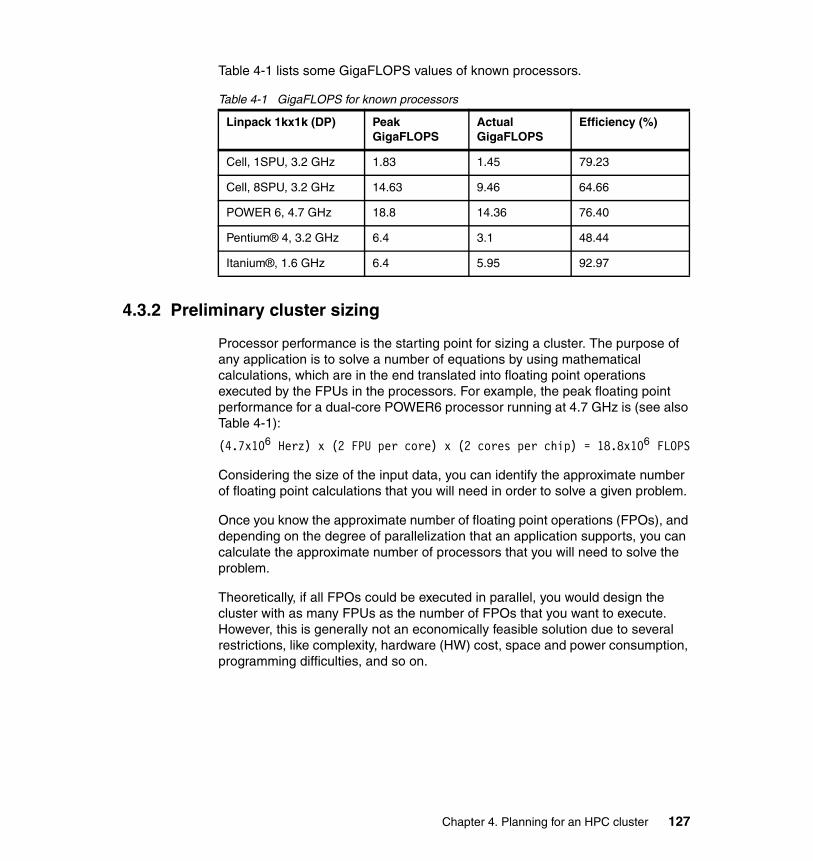
Table 4-1 lists some GigaFLOPS values of known processors.
Table 4-1 GigaFLOPS for known processors
4.3.2 Preliminary cluster sizing
Processor performance is the starting point for sizing a cluster. The purpose of any application is to solve a number of equations by using mathematical calculations, which are in the end translated into floating point operations executed by the FPUs in the processors. For example, the peak floating point performance for a dual-core POWER6 processor running at 4.7 GHz is (see also Table 4-1):
(4.7x10⁶ Herz) x (2 FPU per core) x (2 cores per chip) = 18.8x10⁶ FLOPS
Considering the size of the input data, you can identify the approximate number of floating point calculations that you will need in order to solve a given problem.
Once you know the approximate number of floating point operations (FPOs), and depending on the degree of parallelization that an application supports, you can calculate the approximate number of processors that you will need to solve the problem.
Theoretically, if all FPOs could be executed in parallel, you would design the cluster with as many FPUs as the number of FPOs that you want to execute. However, this is generally not an economically feasible solution due to several restrictions, like complexity, hardware (HW) cost, space and power consumption, programming difficulties, and so on.
Linpack 1kx1k (DP) Peak GigaFLOPS
Actual GigaFLOPS
Efficiency (%)
Cell, 1SPU, 3.2 GHz 1.83 1.45 79.23
Cell, 8SPU, 3.2 GHz 14.63 9.46 64.66
POWER 6, 4.7 GHz 18.8 14.36 76.40
Pentium® 4, 3.2 GHz 6.4 3.1 48.44
Itanium®, 1.6 GHz 6.4 5.95 92.97
Chapter 4. Planning for an HPC cluster 127
In this case you must look at a compromise solution. Considering the previously mentioned restrictions, you can design an HPC cluster based on:
� The problem size
� CPU characteristics:
– Clock frequency– Number of floating point unit (FPUs) – Levels of cache and their size– Processor efficiency (see column #4 in Table 4-1 on page 127)– Power consumption– And so on
� Server characteristics:
– Number of CPUs– Amount of memory– I/O capabilities– Power consumption– Footprint (server size)
� Connectivity technologies
– Throughput– Latency– Resilience– Manageability
� Software support:
– OS capabilities – Programming libraries– Off-the-shelf applications– Ease of porting applications– And so on
In addition to the previous considerations, overall solution cost further determines the cluster design. When you design such a solution, the initial cost (HW, SW, implementation) is often just a fraction of the long-term operating costs of your HPC environment, so you must also consider long-term costs of operating your cluster (power and cooling, HW and SW maintenance, cluster administration, and so on).
4.3.3 The role of benchmarks
As previously mentioned, most of the time application benchmarks are the basis for weighing the efficiency of a HPC system. A selection of benchmarks, often called a benchmark suite, will most likely be part of the tender material.
128 HPC Clusters Using InfiniBand on IBM Power Systems Servers
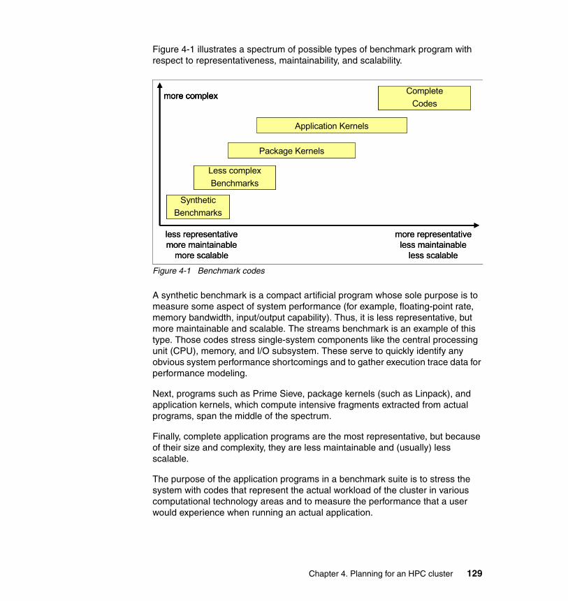
Figure 4-1 illustrates a spectrum of possible types of benchmark program with respect to representativeness, maintainability, and scalability.
Figure 4-1 Benchmark codes
A synthetic benchmark is a compact artificial program whose sole purpose is to measure some aspect of system performance (for example, floating-point rate, memory bandwidth, input/output capability). Thus, it is less representative, but more maintainable and scalable. The streams benchmark is an example of this type. Those codes stress single-system components like the central processing unit (CPU), memory, and I/O subsystem. These serve to quickly identify any obvious system performance shortcomings and to gather execution trace data for performance modeling.
Next, programs such as Prime Sieve, package kernels (such as Linpack), and application kernels, which compute intensive fragments extracted from actual programs, span the middle of the spectrum.
Finally, complete application programs are the most representative, but because of their size and complexity, they are less maintainable and (usually) less scalable.
The purpose of the application programs in a benchmark suite is to stress the system with codes that represent the actual workload of the cluster in various computational technology areas and to measure the performance that a user would experience when running an actual application.
less representativemore maintainable
more scalable
more representativeless maintainable
less scalable
more complex
SyntheticBenchmarks
Less complexBenchmarks
Package Kernels
Application Kernels
CompleteCodes
less representativemore maintainable
more scalable
more representativeless maintainable
less scalable
more complex
SyntheticBenchmarks
Less complexBenchmarks
Package Kernels
Application Kernels
CompleteCodes
more complex
SyntheticBenchmarks
Less complexBenchmarks
Package Kernels
Application Kernels
CompleteCodes
Chapter 4. Planning for an HPC cluster 129

The application program portion of a typical benchmark suite includes the program source code (or directions for obtaining it), makefiles, sample batch submission scripts, and so on. For each program, there are usually different sets of input data, for example, a standard set and a large set. These are called test cases.
Occasionally, the test package includes correct job outputs and quite often scripts for automatically verifying the results of the outputs are included.
Most of the time application tuning is only allowed to a degree and must be discussed with the customer.
It also happens that the offered hardware platform is not available at the time of the procurement as the vendor is offering a future system that is still under development. In this case the benchmarks must be run on a current system and the vendor does projections (extrapolates results) to get performance numbers for the future system. In this case the vendor must convince the purchaser that the projections are valid and reliable.
4.4 Selection options for an HPC system
To design an HPC cluster you must know what are the components of a cluster. In this section we provide an overview of typical HPC cluster components.
130 HPC Clusters Using InfiniBand on IBM Power Systems Servers

4.4.1 How a typical HPC system looks
Figure 4-2 gives an overview of common cluster components.
Figure 4-2 HPC compute cluster components
In the following sections we look closer at each of the areas pictured in Figure 4-2.
Compute node and interconnectThe main hardware components are computer nodes and the interconnect. Those choices usually dictate the application characteristics.
Operating systemThe operating system selection may be influenced by the application suite running on the cluster.
Parallel libraries (MPI)The parallel libraries must be considered in the context of parallel applications, as the applications are build by using these libraries.
Parallel applicationsMost applications must be adapted (ported) to the hardware platform. Optimized libraries will help run those applications efficiently in this environment. This is described in more detail in 4.4.14, “Application development” on page 149.
OS
Parallel Libs - MPI
Parallel ApplicationsCluster Management Tools
WANWAN
Gateway
Interconnect
Compute Nodes
OS
Parallel Libs - MPI
Parallel ApplicationsCluster Management Tools
WANWAN
Gateway
Interconnect
Compute Nodes
Chapter 4. Planning for an HPC cluster 131
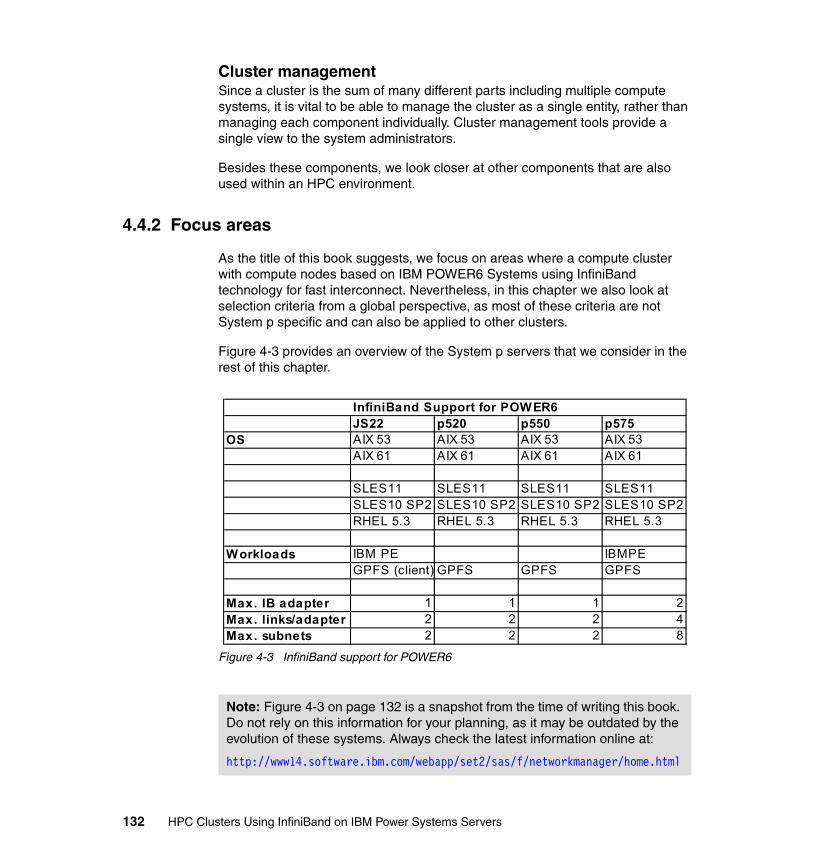
Cluster managementSince a cluster is the sum of many different parts including multiple compute systems, it is vital to be able to manage the cluster as a single entity, rather than managing each component individually. Cluster management tools provide a single view to the system administrators.
Besides these components, we look closer at other components that are also used within an HPC environment.
4.4.2 Focus areas
As the title of this book suggests, we focus on areas where a compute cluster with compute nodes based on IBM POWER6 Systems using InfiniBand technology for fast interconnect. Nevertheless, in this chapter we also look at selection criteria from a global perspective, as most of these criteria are not System p specific and can also be applied to other clusters.
Figure 4-3 provides an overview of the System p servers that we consider in the rest of this chapter.
Figure 4-3 InfiniBand support for POWER6
Note: Figure 4-3 on page 132 is a snapshot from the time of writing this book. Do not rely on this information for your planning, as it may be outdated by the evolution of these systems. Always check the latest information online at:
http://www14.software.ibm.com/webapp/set2/sas/f/networkmanager/home.html
JS22 p520 p550 p575OS AIX 53 AIX 53 AIX 53 AIX 53
AIX 61 AIX 61 AIX 61 AIX 61
SLES11 SLES11 SLES11 SLES11SLES10 SP2 SLES10 SP2 SLES10 SP2 SLES10 SP2RHEL 5.3 RHEL 5.3 RHEL 5.3 RHEL 5.3
Workloads IBM PE IBMPEGPFS (client) GPFS GPFS GPFS
Max. IB adapter 1 1 1 2Max. links/adapter 2 2 2 4Max. subnets 2 2 2 8
InfiniBand Support for POWER6
132 HPC Clusters Using InfiniBand on IBM Power Systems Servers
4.4.3 Compute node criteria
Compute nodes are the main elements of a cluster since they provide the computing power. Principal characteristics of a node are the calculation performance, mainly the floating point performance, the memory performance, and memory capacity. This section focuses on these topics.
Processor architectureThere is still some confusion when using terms like processor and core. In IBM System p, a processor module consists of multiple CPUs, also known as cores, each core having its own arithmetic logic units (ALU), floating point unit (FPU), memory management unit (MMU), branch prediction unit (BPU), instruction cache, data cache, and so on.
Cores in a multi-core device may share a single coherent cache at the highest on-device cache level or may have separate caches. The processors also share the same interconnect with the rest of the system. Each core independently implements optimizations such as superscalar execution, pipelining, and multithreading. A system with n cores is effective when it is presented with n or more threads concurrently.
Floating point unitsAlthough each core also has integer ALUs, for HPC applications, the floating point units are the ones that do the actual work. One way to increase the number of FLOPs is to is to increase the number of floating point units on a core. Another choice is to increase the processor operating frequency. The current POWER processors have two FPUs per core.
MultithreadingMultithreading means that program threads share the resources of a single core:
� The computing units� The CPU caches � The translation lookaside buffer (TLB)
Multithreading aims to increase utilization of a single core by leveraging thread-level as well as instruction-level parallelism.
For IBM Power Systems, multithreading virtually doubles the number of processors seen by the operating system (two threads per core).
Memory bandwidthMemory bandwidth available per processor is a feature that is becoming prevalent as node and chip processor numbers are increasing. In this context, memory interconnect technologies that are scalable with the number of cores per
Chapter 4. Planning for an HPC cluster 133
processor are demanded. Crossbar switching is still used on some large subnet management packets (SMPs) but newer technologies like the distributed switch used in the IBM POWER6 servers have appeared. They reduce the latency compared with large crossbar switch-based systems.
Memory capacityMemory capacity per node is also an important feature since some applications need a large amount of memory per core to run efficiently. Memory performance can be very important for some applications since memory performance has increased at a much slower rate than processor performance.
Acceleration unit extensionsUp to now we only have focused on homogenous compute clusters, at least regarding only the compute nodes.
It is effective to combine general-purpose nodes or processors with special acceleration units to offload some calculation work to these units. Application acceleration technologies such as the Cell Broadband Engine™, field programmable gate arrays (FPGAs), and general purpose graphics processing units (GPGPUs) have the potential to improve some application performance.
This can lead to a massive savings in power, cooling, and management costs by reducing the number of power hungry machines required to achieve a fast time to result.
4.4.4 Special purpose nodes
In addition to compute nodes, an HPC computer cluster will also employ special purpose nodes. We look closely at these types of nodes in the remaining part of this section.
Login (front end) nodesAs the names implies, cluster users log in and submit their work from these nodes. Most times normal users do not have direct access to any other cluster node. For these reasons the login nodes must be quite powerful (I/O and compile capabilities). They are often the same node type as the compute nodes but will have probably more memory, as application development usually requires a lot of compute resources.
Note: As can be seen in the POWER6 server matrix in Figure 4-4 on page 137, based on its characteristics (architecture, cache, frequency), the IBM Power System p575 is the ideal candidate for a compute node.
134 HPC Clusters Using InfiniBand on IBM Power Systems Servers
As these nodes should be reachable from the outside world, they should also have additional adapters for these connections. We recommend using redundant links to the outside world. If the login nodes are no longer reachable due to adapter failure, clusters cannot be used.
I/O nodesI/O nodes are used as interfaces to the persistent storage subsystem or as gateway nodes connecting the cluster to the outside world.
For these nodes, p520 or p550 systems are also options. They offer more adapter slots in the central electronic complex (CEC) compared with a p575 server and the I/O capability can be extended by connecting I/O expansion drawers.
IBM p575 servers can also be used as I/O nodes, but CPU power of this server will most likely not get exhausted, which makes using these nodes for I/O an overkill. The price/performance favors p520 and p550 as I/O servers.
Selecting p520 or p550 as an I/O server might make the setup of the cluster more complicated, depending on the number of IB subnets utilized. When the IB interconnect is using more than two IB links (that is, 4 or 8 links), you must come up with a smart distribution scheme for the integration of p520 or p550 I/O servers into the cluster, as they support only a maximum of two IB links. The next section provides detailed information about this topic.
4.4.5 Type of interconnect
The interconnect is important because many cluster applications spend 10% to 30% (sometimes more) of their time in passing messages between nodes in the cluster. Speeding up the interconnect can improve the performance of the cluster. Interconnect may also be important for reducing the time that it takes to load job data and store job results.
Many different interconnect families are in use today, including Gigabit Ethernet, 10 Gigabit Ethernet, InfiniBand, and others. As we only focus on InfiniBand in this book we make no exception in this section.
One requirement for the interconnect bandwidth is that the ratio between the computing performance of the shared memory nodes and the communication performance between the nodes must be proportional to the number of nodes.
Chapter 4. Planning for an HPC cluster 135

Multiple physical links (planes)As the performance enhancements for network bandwidth over the last couple of years could not keep up with the performance enhancements of the compute server we must find workarounds to overcome this limitation.
One effective vehicle is using multiple physical network connections between the nodes and combining them into one virtual network.
IBM has used this technique in earlier HPC products, like the IBM High Performance Switch (HPS). Within an HPS network up to four physical networks, called planes, build one logical network.
With InfiniBand we use the same concept. This time we support one, two, four, or eight plane networks, based on InfiniBand technology.
The supported InfiniBand switch portfolio was described in 2.6, “InfiniBand switches” on page 77.
For configurations with more than 144 nodes, IBM recommends using an external server to host the IB fabric management software (host subnet manager, HSM). In this case, two ports of the bigger switches are reserved for the HSM connection. More information about the fabric management can be found in Chapter 3, “Technical description of software components” on page 87, and Chapter 6, “Configuring the InfiniBand fabric” on page 177.
The following parameters are needed to design the IB switch environment:
� The maximum number of nodes per cluster� Number of planes � Is redundancy required for the fabric management?
We discuss each of these areas in the remaining part of this section.
IB switch selectionThe maximum number of cluster nodes points to the correct IB switch. However, if the cluster could be extended in the near future, it might be an option to select the next bigger chassis and equip it only with the number of IB ports currently required. The switch can be extended later by only adding additional IB ports.
The following list provides recommendation for which switch should be selected depending on the number of nodes:
� For 1: 24 nodes, use 7874-024� For 25: 48 nodes, use 7874-040� For 49: 144 nodes, use 7874-120� For 145: 286 nodes, use 7874-240
136 HPC Clusters Using InfiniBand on IBM Power Systems Servers
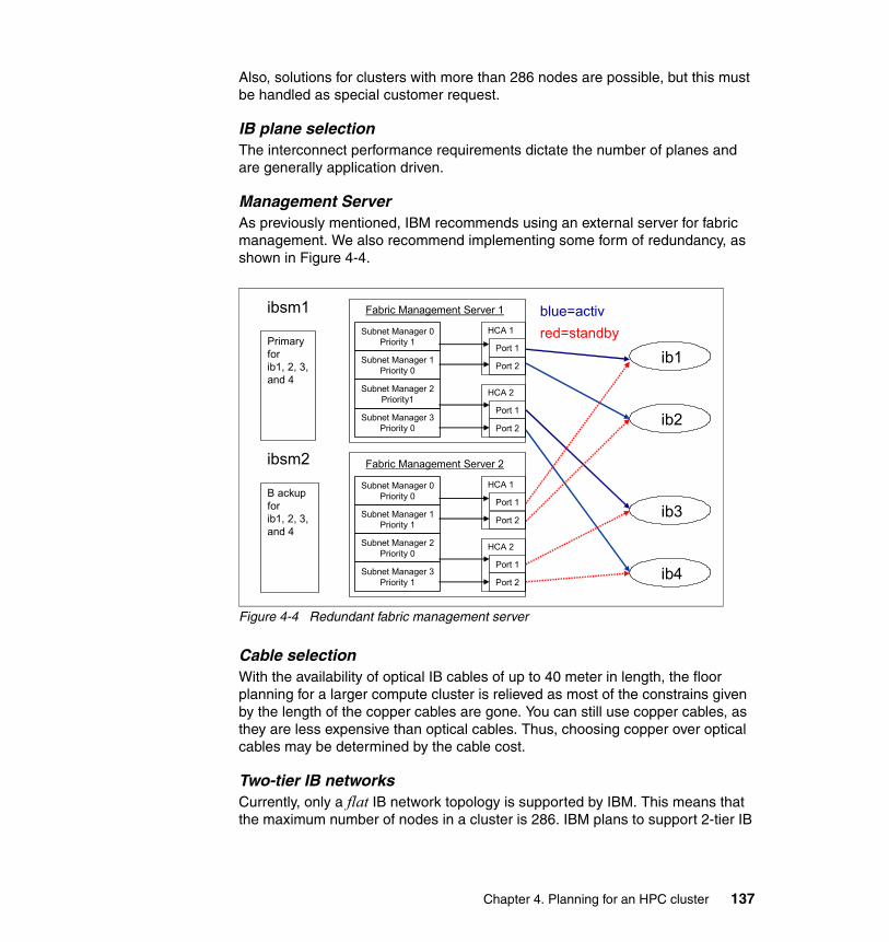
Also, solutions for clusters with more than 286 nodes are possible, but this must be handled as special customer request.
IB plane selectionThe interconnect performance requirements dictate the number of planes and are generally application driven.
Management ServerAs previously mentioned, IBM recommends using an external server for fabric management. We also recommend implementing some form of redundancy, as shown in Figure 4-4.
Figure 4-4 Redundant fabric management server
Cable selectionWith the availability of optical IB cables of up to 40 meter in length, the floor planning for a larger compute cluster is relieved as most of the constrains given by the length of the copper cables are gone. You can still use copper cables, as they are less expensive than optical cables. Thus, choosing copper over optical cables may be determined by the cable cost.
Two-tier IB networksCurrently, only a flat IB network topology is supported by IBM. This means that the maximum number of nodes in a cluster is 286. IBM plans to support 2-tier IB
Subnet Manager 0Priority 1
Subnet Manager 1Priority 0
Subnet Manager 2Priority1
Subnet Manager 3Priority 0
Fabric Management Server 1
Port 1
Port 2
HCA 2
Port 1
Port 2
HCA 1
ib1
ib2
Subnet Manager 0Priority 0
Subnet Manager 1Priority 1
Subnet Manager 2Priority 0
Subnet Manager 3Priority 1
Fabric Management Server 2
Port 1
Port 2
HCA 2
Port 1
Port 2
HCA 1
ib3
ib4
ibsm1
ibsm2
Primaryforib1, 2, 3,and 4
B ackupforib1, 2, 3, and 4
blue=activred=standby
Chapter 4. Planning for an HPC cluster 137
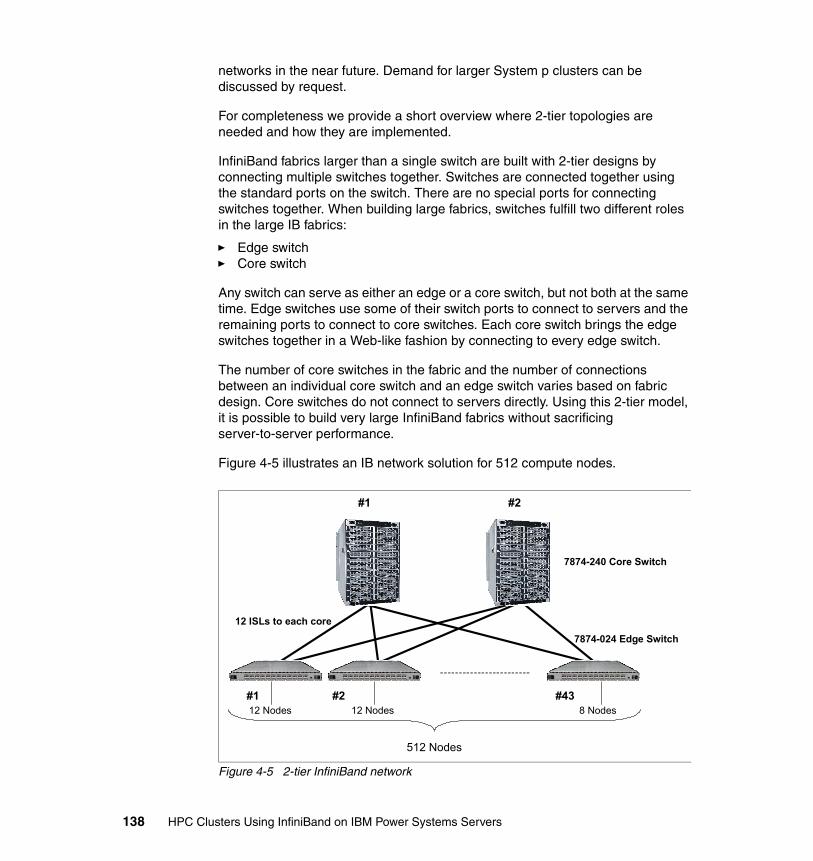
networks in the near future. Demand for larger System p clusters can be discussed by request.
For completeness we provide a short overview where 2-tier topologies are needed and how they are implemented.
InfiniBand fabrics larger than a single switch are built with 2-tier designs by connecting multiple switches together. Switches are connected together using the standard ports on the switch. There are no special ports for connecting switches together. When building large fabrics, switches fulfill two different roles in the large IB fabrics:
� Edge switch� Core switch
Any switch can serve as either an edge or a core switch, but not both at the same time. Edge switches use some of their switch ports to connect to servers and the remaining ports to connect to core switches. Each core switch brings the edge switches together in a Web-like fashion by connecting to every edge switch.
The number of core switches in the fabric and the number of connections between an individual core switch and an edge switch varies based on fabric design. Core switches do not connect to servers directly. Using this 2-tier model, it is possible to build very large InfiniBand fabrics without sacrificing server-to-server performance.
Figure 4-5 illustrates an IB network solution for 512 compute nodes.
Figure 4-5 2-tier InfiniBand network
12 Nodes
512 Nodes
#1 #2
#1 #2 #43
12 ISLs to each core
7874-240 Core Switch
7874-024 Edge Switch
12 Nodes 8 Nodes
138 HPC Clusters Using InfiniBand on IBM Power Systems Servers
As you can see, in total, forty-three 24-port IB-switches and two 288-port IB switches are needed for a 512 compute mode cluster.
4.4.6 Additional networks
The fast interconnect network is not the only network needed in an HPC cluster. For managing and monitoring a cluster a dedicated network is needed were all components like nodes, switches, management units, frame, and so on, are connected to this network. This network is usually based on 1 Gb Ethernet.
As the number of required ports can become quite huge, Ethernet switches can also become a cost issue.
The management network is usually not designed to be fault tolerant, as many installations have proven that these components are very reliable and short downtimes can be tolerated. Nevertheless, if running an application depends on the management network, high availability should be considered to improve overall cluster reliability and productivity.
4.4.7 Public IP addresses: IP address ranges
The two previous sections show that a large compute cluster has many network ports connected to the various networks. All these ports must have IP addresses.
Plan which of these networks must have public IP addresses and which ones can run with private addresses. Make sure that sufficient address ranges are available.
4.4.8 Operating system selection
The operating system selection mostly depends on whether the applications are supported on this OS and whether the future owner of the system already is skilled in this area. Often user are not willing to build up skills for a new operating system.
See Figure 4-3 on page 132 for information about the supported operating system for IBM System p server used in an HPC environment.
4.4.9 Storage options
High performance computing systems are often compared in terms of their floating point performance, communication speed, and available node memory.
Chapter 4. Planning for an HPC cluster 139
However, as applications become larger they also must deal with more data, and this can become just as much of a bottleneck as the actual computation.
Normally, application data is fed into the cluster from some kind of media (persistent storage). Also, application results are saved for further reference (storing, visualization) on some kind of persistent storage. Therefore, there is increasing demand for speeding up input/output (I/O) operations.
The performance of storage devices, such as hard disks, is continuously increasing through technological developments such as faster rotational speed and higher data density on the magnetic media. However, these are not keeping pace with the I/O performance demands of many important scientific and engineering applications.
Although the storage market offers a wide variety of different products, not all qualify to be used in an HPC environment. For example, network-attached storage (NAS) solutions certainly resolve the data-sharing issue, but the underlying architecture is the weak point that cannot meet HPC performance and capacity requirements (single OS image data access).
Furthermore, features like FlashCopy®, remote mirroring, and so on, are not really required for HPC storage. Attributes like scalability, extensibility, data throughput, low latency, and reliability are requested.
As disk drives can perform I/O up to 100 MBps, bandwidth needs of tens to hundreds of gigabytes per second are frequent. Storage selection is often not an independent decision anymore, as the storage selection often goes hand in hand with the parallel file system selection.
You will find several options in the IBM storage portfolio. There is no simple rule that will help for the selection. Usually, it all comes down to the best price/performance solution for a new configuration.
4.4.10 Parallel file systems
High-performance computing environments require parallel file systems. Traditional single-host file systems (for example, those exported via Network File System, NFS) are unable to efficiently scale to support hundreds of nodes. Parallel (clustered) file systems are typically deployed for dedicated high-performance storage solutions within clusters.
The cluster file system market itself is complex, with offerings from several vendors. Also, the latest Linux distributions include some type of parallel file system.
140 HPC Clusters Using InfiniBand on IBM Power Systems Servers
The IBM offer is General Parallel File System (GPFS), which is a high-performance shared-disk cluster file system. GPFS distinguishes itself from other cluster file systems by providing concurrent high-speed file access to applications executing on multiple nodes of an AIX cluster, a Linux cluster, or a heterogeneous cluster of AIX and Linux nodes and lately also Windows nodes as GPFS clients.
In addition to providing file system storage capabilities, GPFS provides tools for management and administration of the GPFS cluster and allows for shared access to file systems from remote GPFS clusters.
GPFS provides unparalleled performance, especially for larger data objects and excellent performance for large aggregates of smaller objects. GPFS achieves high performance I/O by:
� Striping data across multiple disks attached to multiple nodes.
� High-performance metadata (inode) scans.
� Supporting a large block size, configurable by the administrator, to fit I/O requirements.
� Utilizing advanced algorithms that improve read-ahead and write-behind file functions.
� Using block-level locking based on a very sophisticated token management system to provide data consistency while allowing multiple application nodes concurrent access to the files.
GPFS recognizes typical access patterns like sequential, reverse sequential, and random, and optimizes I/O access for these patterns.
GPFS information lifecycle management (ILM)Later GPFS versions have been designed to help you to implement data lifecycle management through policy-driven automation and tiered storage management. The use of storage pools, filesets, and user-defined policies provide the ability to better match the cost of storage to the value of data.
Information lifecycle management policy scans are distributed across multiple servers, which allows GPFS to quickly scan the entire file system, identifying files that match a specific criteria. The ILM policy scan results are taken as input for any hierarchical storage management system, like HSM or HPSS.
Chapter 4. Planning for an HPC cluster 141
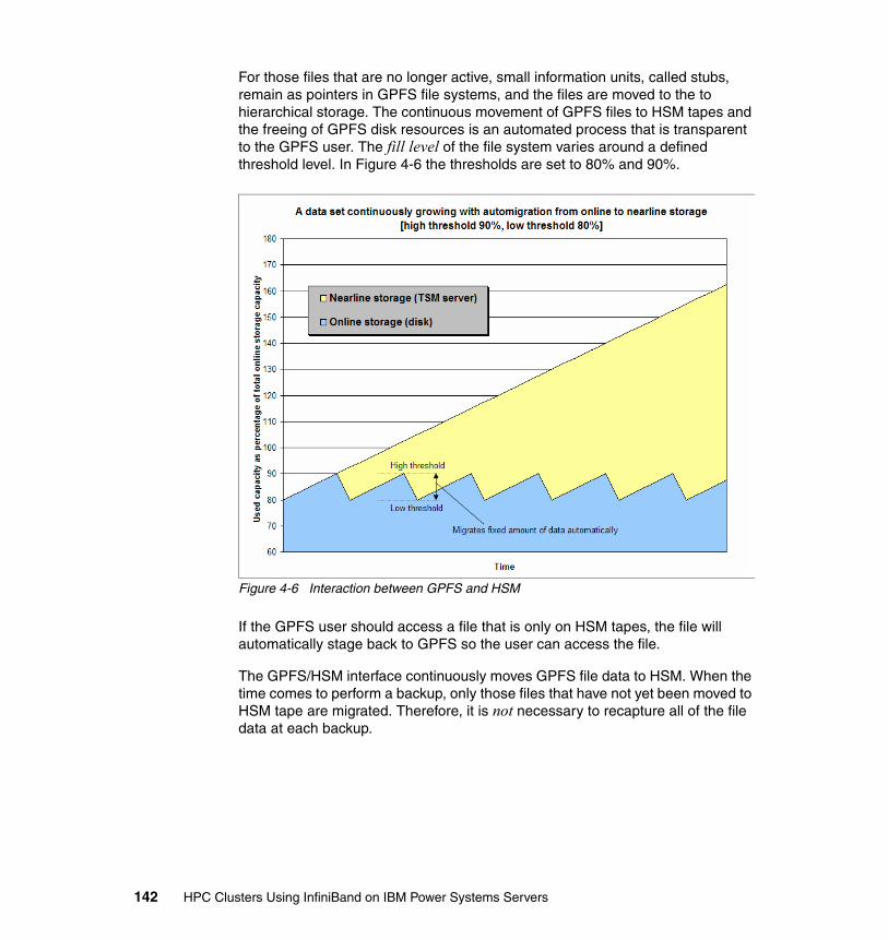
For those files that are no longer active, small information units, called stubs, remain as pointers in GPFS file systems, and the files are moved to the to hierarchical storage. The continuous movement of GPFS files to HSM tapes and the freeing of GPFS disk resources is an automated process that is transparent to the GPFS user. The fill level of the file system varies around a defined threshold level. In Figure 4-6 the thresholds are set to 80% and 90%.
Figure 4-6 Interaction between GPFS and HSM
If the GPFS user should access a file that is only on HSM tapes, the file will automatically stage back to GPFS so the user can access the file.
The GPFS/HSM interface continuously moves GPFS file data to HSM. When the time comes to perform a backup, only those files that have not yet been moved to HSM tape are migrated. Therefore, it is not necessary to recapture all of the file data at each backup.
142 HPC Clusters Using InfiniBand on IBM Power Systems Servers
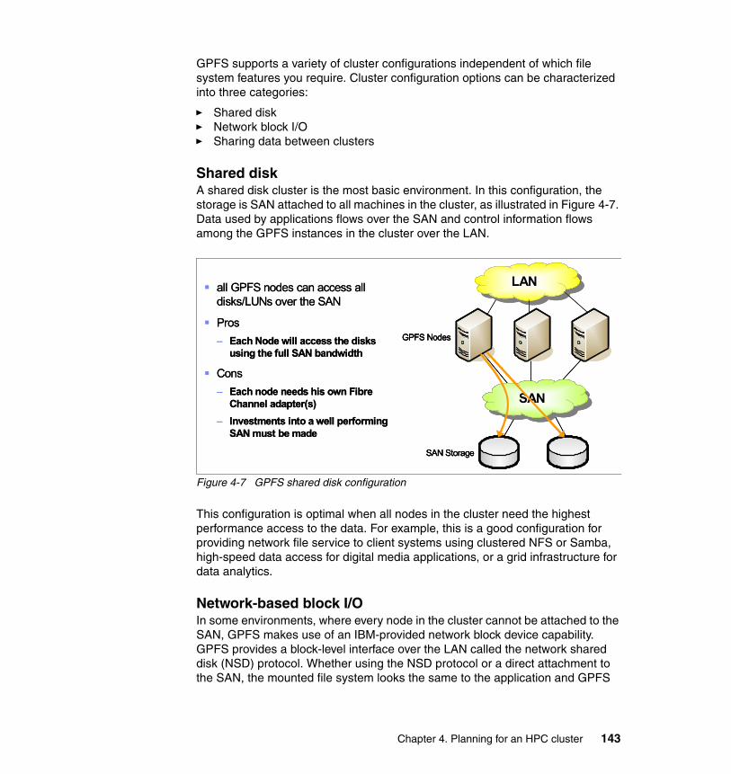
GPFS supports a variety of cluster configurations independent of which file system features you require. Cluster configuration options can be characterized into three categories:
� Shared disk� Network block I/O� Sharing data between clusters
Shared diskA shared disk cluster is the most basic environment. In this configuration, the storage is SAN attached to all machines in the cluster, as illustrated in Figure 4-7. Data used by applications flows over the SAN and control information flows among the GPFS instances in the cluster over the LAN.
Figure 4-7 GPFS shared disk configuration
This configuration is optimal when all nodes in the cluster need the highest performance access to the data. For example, this is a good configuration for providing network file service to client systems using clustered NFS or Samba, high-speed data access for digital media applications, or a grid infrastructure for data analytics.
Network-based block I/OIn some environments, where every node in the cluster cannot be attached to the SAN, GPFS makes use of an IBM-provided network block device capability. GPFS provides a block-level interface over the LAN called the network shared disk (NSD) protocol. Whether using the NSD protocol or a direct attachment to the SAN, the mounted file system looks the same to the application and GPFS
all GPFS nodes can access all disks/LUNs over the SAN
Pros– Each Node will access the disks
using the full SAN bandwidth
Cons– Each node needs his own Fibre
Channel adapter(s)– Investments into a well performing
SAN must be made
SANSAN
GPFS Nodes
SAN Storage
LANLANall GPFS nodes can access all disks/LUNs over the SAN
Pros– Each Node will access the disks
using the full SAN bandwidth
Cons– Each node needs his own Fibre
Channel adapter(s)– Investments into a well performing
SAN must be made
SANSAN
GPFS Nodes
SAN Storage
SANSAN
GPFS Nodes
SAN Storage
LANLAN
Chapter 4. Planning for an HPC cluster 143
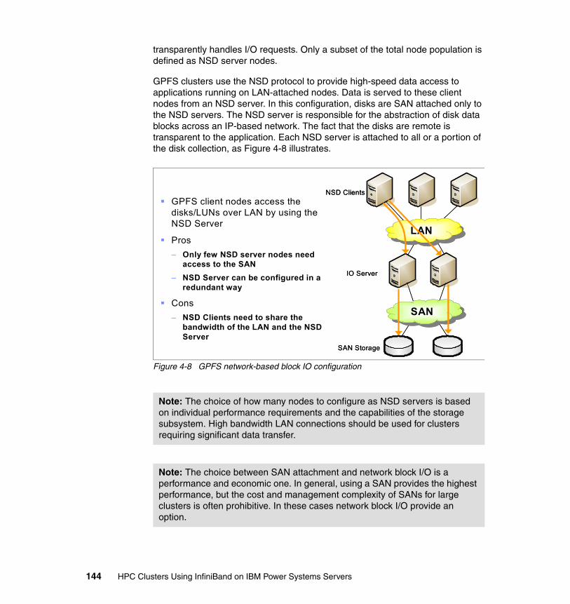
transparently handles I/O requests. Only a subset of the total node population is defined as NSD server nodes.
GPFS clusters use the NSD protocol to provide high-speed data access to applications running on LAN-attached nodes. Data is served to these client nodes from an NSD server. In this configuration, disks are SAN attached only to the NSD servers. The NSD server is responsible for the abstraction of disk data blocks across an IP-based network. The fact that the disks are remote is transparent to the application. Each NSD server is attached to all or a portion of the disk collection, as Figure 4-8 illustrates.
Figure 4-8 GPFS network-based block IO configuration
Note: The choice of how many nodes to configure as NSD servers is based on individual performance requirements and the capabilities of the storage subsystem. High bandwidth LAN connections should be used for clusters requiring significant data transfer.
Note: The choice between SAN attachment and network block I/O is a performance and economic one. In general, using a SAN provides the highest performance, but the cost and management complexity of SANs for large clusters is often prohibitive. In these cases network block I/O provide an option.
GPFS client nodes access thedisks/LUNs over LAN by using theNSD Server
Pros– Only few NSD server nodes need
access to the SAN– NSD Server can be configured in a
redundant way
Cons– NSD Clients need to share the
bandwidth of the LAN and the NSD Server
NSD Clients
IO Server
SAN Storage
LANLAN
SANSAN
NSD Clients
IO Server
SAN Storage
LANLAN
SANSAN
144 HPC Clusters Using InfiniBand on IBM Power Systems Servers
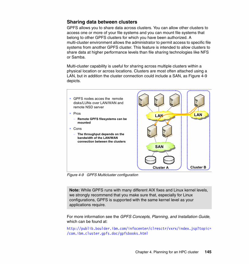
Sharing data between clustersGPFS allows you to share data across clusters. You can allow other clusters to access one or more of your file systems and you can mount file systems that belong to other GPFS clusters for which you have been authorized. A multi-cluster environment allows the administrator to permit access to specific file systems from another GPFS cluster. This feature is intended to allow clusters to share data at higher performance levels than file sharing technologies like NFS or Samba.
Multi-cluster capability is useful for sharing across multiple clusters within a physical location or across locations. Clusters are most often attached using a LAN, but in addition the cluster connection could include a SAN, as Figure 4-9 depicts.
Figure 4-9 GPFS Multicluster configuration
For more information see the GPFS Concepts, Planning, and Installation Guide, which can be found at:
http://publib.boulder.ibm.com/infocenter/clresctr/vxrx/index.jsp?topic=/com.ibm.cluster.gpfs.doc/gpfsbooks.html
Note: While GPFS runs with many different AIX fixes and Linux kernel levels, we strongly recommend that you make sure that, especially for Linux configurations, GPFS is supported with the same kernel level as your applications require.
GPFS nodes acces the remotedisks/LUNs over LAN/WAN and remote NSD server
Pros– Remote GPFS filesystems can be
mounted
Cons– The throughput depends on the
bandwidth of the LAN/WAN connection between the clusters
LANLAN
SANSAN
Cluster A
LANLAN
Cluster B
Chapter 4. Planning for an HPC cluster 145
4.4.11 Backup/archive considerations
File archiving and backup systems have two distinct and complementary functions within an enterprise:
� Backup for high-speed copy and restore to minimize the impact of failures, human error, or disaster
� Archiving to effectively manage data for retention and long-term access and retrieval
These two capabilities can be applied together to optimize the cost and improve the overall effectiveness of any storage infrastructure.
Usually, parallel applications generate enormeous quantities of data. These must be stored for decades in order to compare and evaluate the results (for example, climate research). This implies a hierarchical storage management system with different levels of storage devices.
For transparent access this feature should be implemented on top of the parallel file system described above, or even better be an integrated part of it. Since the data (number of I/O nodes, metadata information concerning the tape media) will continuously increase, huge scalable databases will be required.
Integration in an existing backup/archive environmentMost large computer centers have already implemented backup/archive (B/A) environments. If the new HPC cluster is either a replacement of an older system or an enhancement to an existing one, this cluster must be integrated in the existing B/A environment. In this case you must make sure that the new cluster is supported by the B/A software. Also, you must verify that your HPC cluster can be physically connected to the B/A system in terms of network connections or direct attached via adapter, like, for example, Fibre Channel adapter.
If these prerequisites are met, you must get the correct skills for the implementation and figure out what will be the costs of this integration project (additional network bandwidth, media requirements, and so on).
New implementation of a B/A systemIn this case you must figure out which software products are supported on the new platform. The IBM offer can be Tivoli Storage Manager/Hierarchal Storage Management (TSM/HSM) or High Performance Storage System (HPSS), often in combination with GPFS.
As previously mentioned, you must estimate the costs and take this into account for the total costs of the entire cluster.
146 HPC Clusters Using InfiniBand on IBM Power Systems Servers
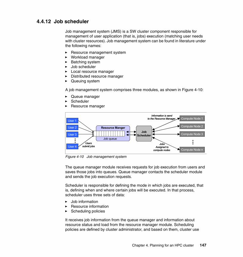
4.4.12 Job scheduler
Job management system (JMS) is a SW cluster component responsible for management of user application (that is, jobs) execution (matching user needs with cluster resources). Job management system can be found in literature under the following names:
� Resource management system� Workload manager� Batching system� Job scheduler� Local resource manager� Distributed resource manager� Queuing system
A job management system comprises three modules, as shown in Figure 4-10:
� Queue manager� Scheduler� Resource manager
Figure 4-10 Job management system
The queue manager module receives requests for job execution from users and saves those jobs into queues. Queue manager contacts the scheduler module and sends the job execution requests.
Scheduler is responsible for defining the mode in which jobs are executed, that is, defining when and where certain jobs will be executed. In that process, scheduler uses three sets of data:
� Job information� Resource information � Scheduling policies
It receives job information from the queue manager and information about resource status and load from the resource manager module. Scheduling policies are defined by cluster administrator, and based on them, cluster use
Resource Manger
User 1
User 2
User 3
User 4
…
Job queueUsers
submit jobs
Compute Node 1
JobScheduler
Compute Node 2
Compute Node 3
Compute Node n
…
Information is sendto the Resource Manager
JobsAssigned to
compute nodes
Resource Manger
User 1
User 2
User 3
User 4
…
Job queueUsers
submit jobs
Compute Node 1
JobScheduler
Compute Node 2
Compute Node 3
Compute Node n
…
Information is sendto the Resource Manager
JobsAssigned to
compute nodes
Chapter 4. Planning for an HPC cluster 147

policy is defined (that is, it is defined which kinds of jobs (for example, longer, shorter, parallel, interactive) have the advantage). The scheduler module is responsible for optimization of cluster resource utilization in accordance with scheduling policy.
Resource manager does not know how to launch multiprocess jobs such as MPI applications. Instead, it is responsible for preparing the environment for job execution, reserving the resources, and then asking the native parallel environment to launch the job.
The job management system tries to achieve a system utilization as close as possible to 100%. Therefore, efficient job scheduling strategies are important to improve the performance and usability of HPC-clusters. As the scheduler has a strong influence on the system performance, it is worthwhile to improve the performance of the scheduling strategy.
Today's job scheduler typically provides a graphical user interface and a single point of control for definition and monitoring of background executions in a distributed network of computers.
Tivoli Workload Scheduler LoadLevelerThe IBM offer of job management system is Tivoli Workload Scheduler LoadLeveler (TWS LoadLeveler). Prior to April 2006 the product was called LoadLeveler and is still known under this name.
TWS LoadLeveler supports AIX, i5/OS®, Linux on x86, Linux on x86-64, Linux on System z®, Linux on POWER, BlueGene, Solaris, and Windows. For any details about the details of the supported OS versions see:
http://www-01.ibm.com/support/docview.wss?rs=672&context=SSGSPN&uid=swg21318454&loc=en_US&cs=utf-8&lang=en
LoadLeveler is a distributed network-wide job management software for scheduling jobs. LoadLeveler provides tools to help users build, submit, and manage batch jobs quickly and effectively in a dynamic environment. Customers can extend the LoadLeveler functions by developing applications using the application programming interface (API) support. One such example is the scheduler developed by the Cornell Theory Center (EASY-LL).
LoadLeveler can be used for workload balancing of both serial and parallel jobs (SMP and MPI parallel). For MPI jobs, a parallel operating environment interfaces with LoadLeveler to obtain the multiple nodes required for the job's parallel tasks.
A graphical user interface is also available on submitting machines for job submission.
148 HPC Clusters Using InfiniBand on IBM Power Systems Servers
For more information see:
http://www-01.ibm.com/software/tivoli/products/scheduler/
4.4.13 Cluster management software
Cluster management software hides the complexity of managing many different cluster components to reduce the administrative task and to better control the cluster. It enables administrators to easily manage large clusters from one single point of control.
Most cluster management software is designed in such a way that the loss of the management server will not interrupt the execution of the current compute job, it will only disrupt monitoring data collection and new job submission. To overcome such situations, fail over to a backup management server is supported by some cluster management packages.
By designing a cluster solution it also worth taking such a high available cluster management solution into account.
IBM offers a complete portfolio of cluster software. The current incarnation is eXtreme Cluster Administration Version 2 (xCAT2), which we recommend for all new deployments.
4.4.14 Application development
From the mid 1980s to the mid 1990s, many applications were ported to parallel distributed memory systems using the message passing libraries available at that time. Then, as standardization and commoditization was taking place in the late decade, those applications have been ported on clusters using MPI.
Those applications have been using HPC resources since the early days. Most of them have evolved from vector to parallel systems and again to clusters, enabling finer and cheaper simulations. Those applications have been used by large public research or industrial customers to simulate real systems (flow around a body, engine combustion, structural analysis, crash simulation, chemistry, material science, and so on), to forecast the behavior of complex systems (weather prediction, climate modeling), or to analyze large amounts of data (seismic processing, image and signal processing, encryption/decryption).
Chapter 4. Planning for an HPC cluster 149
Keep in mind that nearly every application that was not running on a POWER6 platform before must be ported and tuned in order to get the best results out if it. For that you will need the correct tools, such as:
� Compilers� Optimized mathematical libraries� Parallel environment tools� Debuggers
We discuss most of these tools in 3.3, “HPC IB stack overview” on page 110.
4.4.15 Facility considerations
Space, power, and cooling demands in many cases restrict the growth of supercomputers and their support systems.
Space requirementsThinking about space requirements not only means considering the size of the needed floor space, it also means planning the delivery of all cluster components and thinking about the way to get these components to their spots.
Determine the path that must be taken to move the system from the delivery location to the installation site:
� Verify the height of all doorways, elevators, and so on.� Verify the weight limitations of elevators, ramps, floors, floor tiles, and so on.
Often a raised floor is required for systems of that size. Make sure that the environmental, mechanical, and seismic characteristics of the raised floor meet the installation requirements of the HPC cluster.
Power and electrical requirementsEach component in a cluster has specific power requirements. For example, POWER6 575 systems require four power connections, whereas storage frames often need only two power connections.
Make sure that the number of connections, the correct power connectors, the line voltages current input are matched with the correct circuit beakers during the planning and site execution phases.
Note: The porting and tuning work is time consuming. Take this into account for the time schedule of the cluster setup and for the cost calculation.
150 HPC Clusters Using InfiniBand on IBM Power Systems Servers

UPS and backup generatorFor equipment protection and cluster reliability, uninterruptible power supplies (UPS), a backup power generator, or both must be installed.
Cooling requirementsMost systems are air cooled, but the need for cooling parts of a system or complete server with water is increasing. This is another crucial topic during the planning phase. Moreover, cooling also requires additional electrical power planning.
� Air cooling
The cooling requirements of all components of the cluster must be determined and then verified that the capacity of the cooling system is sufficient. It not, it must be enhanced.
� Water cooling
As water can absorb more heat than air and the pumps required to circulate water in a cooling system consume less power than air-conditioning systems, water cooling is becoming more and more an option for cooling IT equipment in data centers.
Currently, only the System p575 servers are water cooled. There are many things that must be considered for the planning. For more details see Site and Hardware Planning Guide, SA76-0091-00.
4.4.16 Maintaining an HPC cluster
For maintaining an HPC at least two things must be considered:
� Maintenance costs � Administrative support
Maintenance costsPower consumption is an important component of total cost of ownership (TCO). It may turn out that the maintenance cost over the run time, which often at about five years, is much higher than acquisition costs. Sometimes these maintenance costs must be included in the total costs of the compute cluster.
Maintenance/administration supportThe HPC cluster customers often require onsite vendor support for the entire run-time period. This comes at an additional cost and should also be considered.
Chapter 4. Planning for an HPC cluster 151
4.4.17 Availability considerations
As outlined in the previous sections, most cluster components are designed to support a redundant operation. This redundant mode is not active by default. You must plan it and set it up. You must plan for:
� Redundant power supplies� Redundant cooling components� Fabric management server high availability� Redundant cluster management server� Redundant InfiniBand plane� Redundant I/O server� Redundant (multiple) login nodes
There are already many cluster components that are redundant by default, like power supplies. Other components support redundancy, but this must be planned and activated, like the redundant cluster management server.
For continuos operation, UPS should be considered. UPS also has the advantage that it filters, conditions, and regulates the power.
You still will find other components that are single points of failure. You must figure out the implications if they fail, what it will cost to avoid this, and, finally, if it is worth the cost. One example is the management network. It it fails, it will not stop the cluster1, which means that all running tasks will continue.
The next question is how long can this failure be tolerated? The answer is probably a couple of minutes. Is it possible to detect the reason for the failure within this time?
If you want to lay out the network in a redundant way you will need a second Ethernet switch and you will need roughly double the amount of Ethernet cables. This can become quite expensive, depending on the size of the switch.
There is no general advice, every case is different and needs well-thought out planning.
4.5 Decision criteria
We have highlighted a lot of factors in the previous sections that you must consider in case you are planning a HPC compute cluster. The list of criteria
1 Depending on current implementation. For example, if the job scheduling mechanism uses the cluster management network, you may consider adding high availability to this network also.
152 HPC Clusters Using InfiniBand on IBM Power Systems Servers
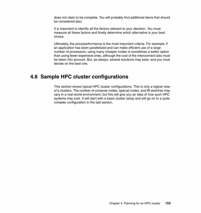
does not claim to be complete. You will probably find additional items that should be considered also.
It is important to identify all the factors relevant to your decision. You must measure all these factors and finally determine which alternative is your best choice.
Ultimately, the price/performance is the most important criteria. For example, if an application has been parallelized and can make efficient use of a large number of processors, using many cheaper nodes is sometimes a better option than using fewer expensive ones, although the cost of the interconnect also must be taken into account. But, as always, several solutions may exist, and you must decide on the best one.
4.6 Sample HPC cluster configurations
This section shows typical HPC cluster configurations. This is only a logical view of a clusters. The number of compute nodes, special nodes, and IB switches may vary in a real-world environment, but this will give you an idea of how such HPC systems may look. It will start with a basic cluster setup and will go on to a quite complex configuration in the last section.
Chapter 4. Planning for an HPC cluster 153
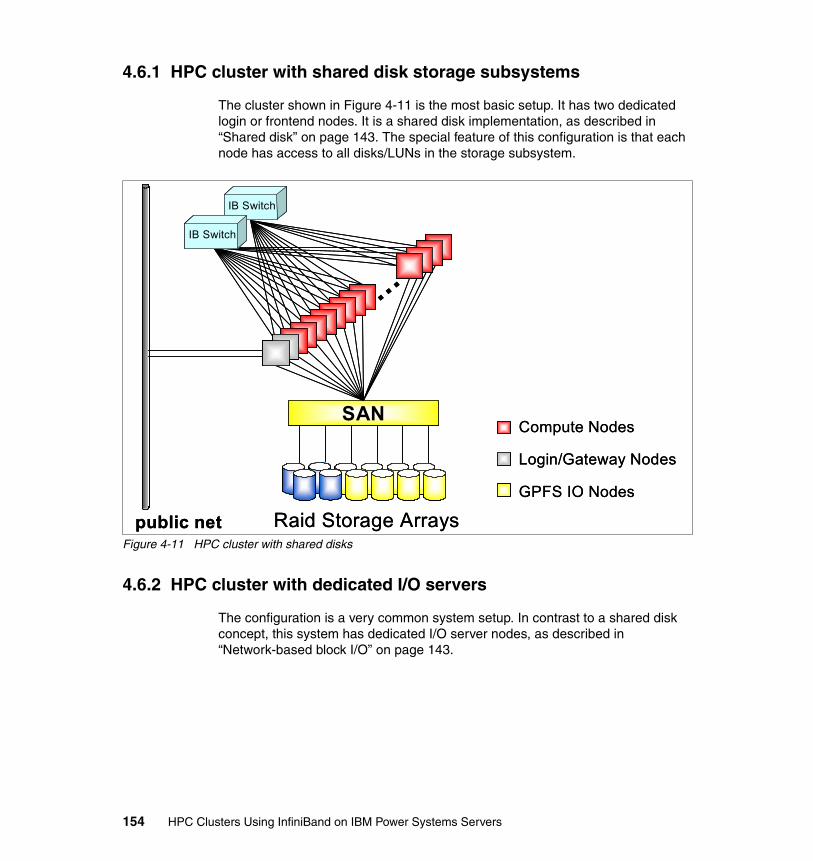
4.6.1 HPC cluster with shared disk storage subsystems
The cluster shown in Figure 4-11 is the most basic setup. It has two dedicated login or frontend nodes. It is a shared disk implementation, as described in “Shared disk” on page 143. The special feature of this configuration is that each node has access to all disks/LUNs in the storage subsystem.
Figure 4-11 HPC cluster with shared disks
4.6.2 HPC cluster with dedicated I/O servers
The configuration is a very common system setup. In contrast to a shared disk concept, this system has dedicated I/O server nodes, as described in “Network-based block I/O” on page 143.
Raid Storage Arrays
SAN
public net
…
IB Switch
IB Switch
Compute Nodes
Login/Gateway Nodes
GPFS IO Nodes
Raid Storage Arrays
SAN
public net
…
IB SwitchIB Switch
IB SwitchIB Switch
Compute Nodes
Login/Gateway Nodes
GPFS IO Nodes
154 HPC Clusters Using InfiniBand on IBM Power Systems Servers
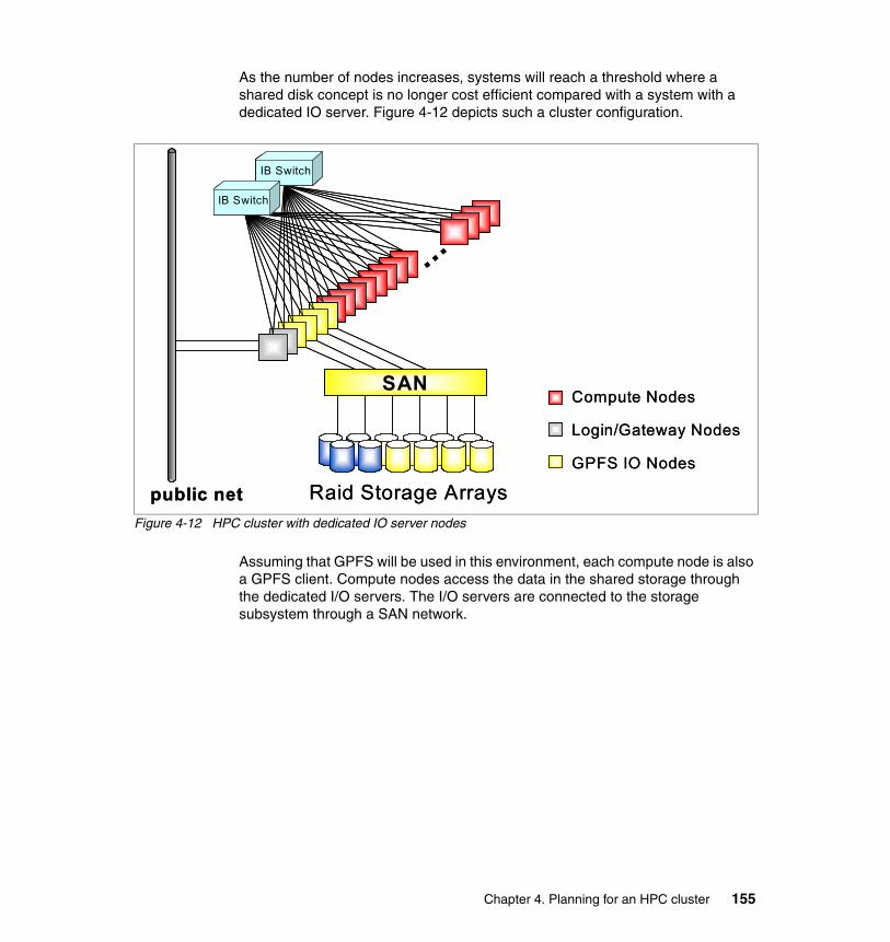
As the number of nodes increases, systems will reach a threshold where a shared disk concept is no longer cost efficient compared with a system with a dedicated IO server. Figure 4-12 depicts such a cluster configuration.
Figure 4-12 HPC cluster with dedicated IO server nodes
Assuming that GPFS will be used in this environment, each compute node is also a GPFS client. Compute nodes access the data in the shared storage through the dedicated I/O servers. The I/O servers are connected to the storage subsystem through a SAN network.
Raid Storage Arrays
SAN
public net
…
IB Switch
IB Switch
Compute Nodes
Login/Gateway Nodes
GPFS IO Nodes
Raid Storage Arrays
SAN
public net
…
IB SwitchIB Switch
IB SwitchIB Switch
Compute Nodes
Login/Gateway Nodes
GPFS IO Nodes
Chapter 4. Planning for an HPC cluster 155
4.6.3 HPC cluster with dedicated I/O servers and archive subsystem
Figure 4-13 illustrates an HPC cluster with additional special nodes:
� Login nodes� I/O nodes� Backup/archive nodes
Figure 4-13 HPC cluster with dedicated GPFS I/O server nodes and archive subsystem
As in the previous configuration, all nodes are connected to the InfiniBand network. In addition to the previous configuration, this configuration has dedicated nodes used for interfacing to an archive system.
We chose HPSS in our example as an archive system, but this can be substituted with any other archive or backup system.
4.6.4 Complex cluster configuration
This section describes a fairly complex HPC cluster. We especially look at the way that the storage subsystem is connected to the rest of the system. As the storage subsystem builds its own cluster you can also name it storage cluster.
Raid Storage Arrays
SAN
…HPSSHPSS
IB Switch
IB Switch
Compute Nodes
Login/Gateway Nodes
GPFS IO Nodes
HPSS Mover Nodespublic net Raid Storage Arrays
SAN
…HPSSHPSS
IB Switch
IB Switch
Raid Storage Arrays
SAN
…HPSSHPSSHPSSHPSS
IB SwitchIB Switch
IB SwitchIB Switch
Compute Nodes
Login/Gateway Nodes
GPFS IO Nodes
HPSS Mover Nodes
Compute Nodes
Login/Gateway Nodes
GPFS IO Nodes
HPSS Mover Nodespublic net
156 HPC Clusters Using InfiniBand on IBM Power Systems Servers
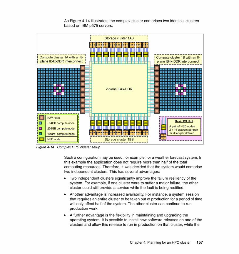
As Figure 4-14 illustrates, the complex cluster comprises two identical clusters based on IBM p575 servers.
Figure 4-14 Complex HPC cluster setup
Such a configuration may be used, for example, for a weather forecast system. In this example the application does not require more than half of the total computing resources. Therefore, it was decided that the system would comprise two independent clusters. This has several advantages:
� Two independent clusters significantly improve the failure resiliency of the system. For example, if one cluster were to suffer a major failure, the other cluster could still provide a service while the fault is being rectified.
� Another advantage is increased availability. For instance, a system session that requires an entire cluster to be taken out of production for a period of time will only affect half of the system. The other cluster can continue to run production work.
� A further advantage is the flexibility in maintaining and upgrading the operating system. It is possible to install new software releases on one of the clusters and allow this release to run in production on that cluster, while the
Storage cluster 1BS
Compute cluster 1A with an 8-plane IB4x-DDR interconnect
N/W node
64GB compute node
256GB compute node
NSD node
2-plane IB4x-DDR
Basic I/O Unit
A pair of NSD nodes 2 x 14 drawers per pair 12 disks per drawer
Storage cluster 1AS
“spare” compute node
Compute cluster 1B with an 8-plane IB4x-DDR interconnect
Chapter 4. Planning for an HPC cluster 157

other cluster runs the earlier software release, until the time comes for it too to be upgraded.
Quite uncommon is the way in which the disk subsystem is connected to both clusters. The user storage is decoupled from the compute clusters and is instead added to a separate cluster, as illustrated in Figure 4-14 on page 157, and a resilient storage fabric provides the SAN.
This architecture provides flexibility, both operationally and in the exploitation of different storage technologies. IBM selected the storage cluster paradigm for the following key reasons:
� Technology flexibility
Storage clusters allow you to deploy any storage that can be shared between two servers in a highly available manner, whereas the Fibre Channel (FC) SAN allows only FC-attached storage to be used. As new storage technology is available, it can be integrated into the system without modifying the configuration of the compute cluster.
� Flexibility in implementation time scales
Various new storage systems and architectures are being developed using multiple attachment methods such as FC, InfiniBand, and SAS. By decoupling the storage from the compute clusters, upgrading the storage exploits the best technologies available to meet performance, rather than tieing upgrades to the compute cluster.
� Operation flexibility
All the applications run on the compute clusters and this is where most software changes and upgrades take place. With this architecture, a compute cluster can be taken down for maintenance or rebooted without impacting the storage clusters or the file systems mounted on the second compute cluster.
� Reliability of storage
The global file systems are a key resource. The storage clusters have been simplified as much as possible and they have no internal interconnect, no applications, and they simply run AIX, GPFS, and cluster management software. With less hardware and software complexity, there will be less change (software or firmware upgrades) and increased reliability.
The storage clusters share a resilient IB 4x double data rate (DDR) network.
As you can see, this is a very flexible approach and is another example of a sophisticated HPC cluster implementation.
158 HPC Clusters Using InfiniBand on IBM Power Systems Servers
Part 3 Implementing InfiniBand
This part provides a basic guide for installation and configuration of InfiniBand in an IBM Power Systems environment. Currently, IBM supports InfiniBand (IB) with AIX and Linux operating systems. We describe the software components that are used to make an IB fabric operational. Operating systems, device drivers, and clustering products for management, availability, and job scheduling come together to form a solution for today’s computing environments.
Part 3
© Copyright IBM Corp. 2009. All rights reserved. 159

160 HPC Clusters Using InfiniBand on IBM Power Systems Servers
Chapter 5. Implementation overview
This chapter provides an overview of the environment that will used within the following chapters of this book. More in-depth chapters provide examples and procedures that can be used to build a working InfiniBand on POWER6 high performance computing (HPC) cluster. Some examples and screen images have been taken from a small environment or may be a subset of the output or commands shown in this and further chapters. However, the functionality will be the same.
5
© Copyright IBM Corp. 2009. All rights reserved. 161
5.1 Environment description
The environment that the examples in the remaining chapters refer to has been built after taking into consideration the requirements listed in Chapter 4, “Planning for an HPC cluster” on page 123.
We believe that this environment will provide a good match to many workloads. However, it may not suit all workloads.
The components of the example environment are:
� 28 x IBM Power 575 nodes (see “IBM POWER6 9125-F2A (p575)” on page 53). These node contain:
– 2 x GX++ adapters per node installed in the available GX+ slots as described in “HCA for POWER6 9125-F2A” on page 72.
– 4 x of the nodes will be attached to the storage fabric using 4 GB HBAs and will be used to provide direct-attached GPFS NSD connectivity.
� 8 x IBM 7874 InfiniBand switches, as described in 2.6, “InfiniBand switches” on page 77. These are be configured with:
– Two managed spines per hemisphere and one unmanaged spine per hemisphere
– All redundancy options installed (for example, full complement of fans and power supplies)
– Two leafs installed per hemisphere
� 4 x QLogic Fabric Manager servers, redundantly configured in two pairs, as described in 3.2.2, “Fabric Management Server” on page 103. These servers must run SLES 10 SP2.
� 4 x IBM power HMC as described in 2.2.2, “Hardware Management Console (HMC)” on page 60
� 2 x IBM M42 SAN switches (used for GPFS direct-attached NSD servers).
� IBM DS8300 Storage Arrays, connected through redundant IBM SVC nodes (used for GPFS NSDs).
� 1 x IBM Power 550, for use as an xCAT2 Management Server.
� GPFS cluster file system.
� IBM HPC software stack.
162 HPC Clusters Using InfiniBand on IBM Power Systems Servers
Benefits of this solution include:
� Single vendor support for all cluster components
� Small footprint and high density (One compute node rack has 952 processors.)
� Versatility of general-purpose RISC processors employing IBM state-of-art POWER6 technology
� Proven cluster management and HPC software stack
The compute nodes in our environment have been configured to boot into two different operating systems, AIX 6.1 TL3 or SLES 11.
Procedures for operating systems are detailed for AIX in Chapter 7, “Configuring InfiniBand on AIX” on page 205, and for SLES 11 in Chapter 8, “Configuring InfiniBand on Linux on Power” on page 235.
Additionally, both AIX and SUSE Linux Enterprise Server (SLES) implementations in this book were configured using the local /etc/hosts file for name resolution. A sample script and a description of how it is used is provided in 10.1.1, “xCAT2 InfiniBand management on AIX and Linux” on page 340.
5.1.1 Network topology
As described in 3.2.1, “Network definitions” on page 101, a number of separate networks are required. These can be either logically separated (IP subnetting or VLANs), or in the case of a cluster/data network, physically separated networks should be used also.
In our example implementation, we use gigabit Ethernet switches (for fast node deployment and management), divided logically into the networks discussed in this section.
Note: The IP addresses and labels used here are just for reference. Your environment must be planned carefully and discussed with your network design and administration team.
Chapter 5. Implementation overview 163
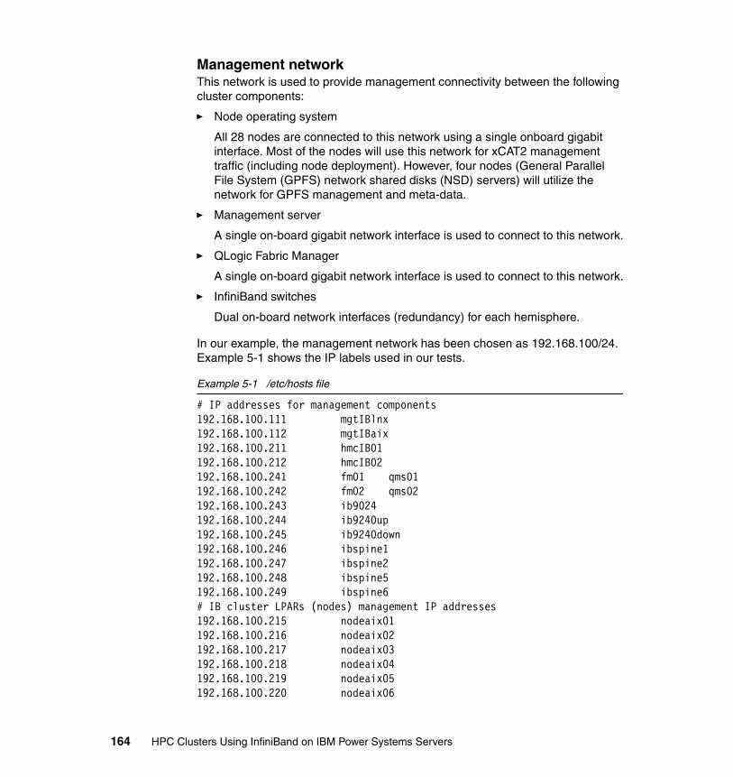
Management networkThis network is used to provide management connectivity between the following cluster components:
� Node operating system
All 28 nodes are connected to this network using a single onboard gigabit interface. Most of the nodes will use this network for xCAT2 management traffic (including node deployment). However, four nodes (General Parallel File System (GPFS) network shared disks (NSD) servers) will utilize the network for GPFS management and meta-data.
� Management server
A single on-board gigabit network interface is used to connect to this network.
� QLogic Fabric Manager
A single on-board gigabit network interface is used to connect to this network.
� InfiniBand switches
Dual on-board network interfaces (redundancy) for each hemisphere.
In our example, the management network has been chosen as 192.168.100/24. Example 5-1 shows the IP labels used in our tests.
Example 5-1 /etc/hosts file
# IP addresses for management components192.168.100.111 mgtIBlnx192.168.100.112 mgtIBaix192.168.100.211 hmcIB01192.168.100.212 hmcIB02192.168.100.241 fm01 qms01192.168.100.242 fm02 qms02192.168.100.243 ib9024192.168.100.244 ib9240up192.168.100.245 ib9240down192.168.100.246 ibspine1192.168.100.247 ibspine2192.168.100.248 ibspine5192.168.100.249 ibspine6# IB cluster LPARs (nodes) management IP addresses192.168.100.215 nodeaix01192.168.100.216 nodeaix02192.168.100.217 nodeaix03192.168.100.218 nodeaix04192.168.100.219 nodeaix05192.168.100.220 nodeaix06
164 HPC Clusters Using InfiniBand on IBM Power Systems Servers
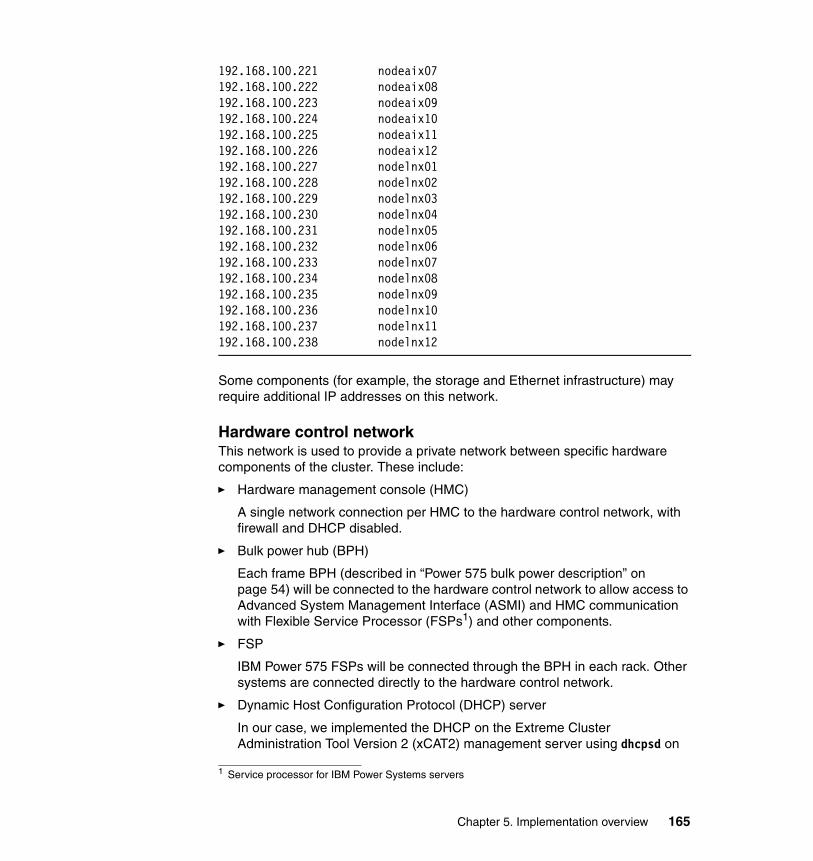
192.168.100.221 nodeaix07192.168.100.222 nodeaix08192.168.100.223 nodeaix09192.168.100.224 nodeaix10192.168.100.225 nodeaix11192.168.100.226 nodeaix12192.168.100.227 nodelnx01192.168.100.228 nodelnx02192.168.100.229 nodelnx03192.168.100.230 nodelnx04192.168.100.231 nodelnx05192.168.100.232 nodelnx06192.168.100.233 nodelnx07192.168.100.234 nodelnx08192.168.100.235 nodelnx09192.168.100.236 nodelnx10192.168.100.237 nodelnx11192.168.100.238 nodelnx12
Some components (for example, the storage and Ethernet infrastructure) may require additional IP addresses on this network.
Hardware control networkThis network is used to provide a private network between specific hardware components of the cluster. These include:
� Hardware management console (HMC)
A single network connection per HMC to the hardware control network, with firewall and DHCP disabled.
� Bulk power hub (BPH)
Each frame BPH (described in “Power 575 bulk power description” on page 54) will be connected to the hardware control network to allow access to Advanced System Management Interface (ASMI) and HMC communication with Flexible Service Processor (FSPs1) and other components.
� FSP
IBM Power 575 FSPs will be connected through the BPH in each rack. Other systems are connected directly to the hardware control network.
� Dynamic Host Configuration Protocol (DHCP) server
In our case, we implemented the DHCP on the Extreme Cluster Administration Tool Version 2 (xCAT2) management server using dhcpsd on
1 Service processor for IBM Power Systems servers
Chapter 5. Implementation overview 165
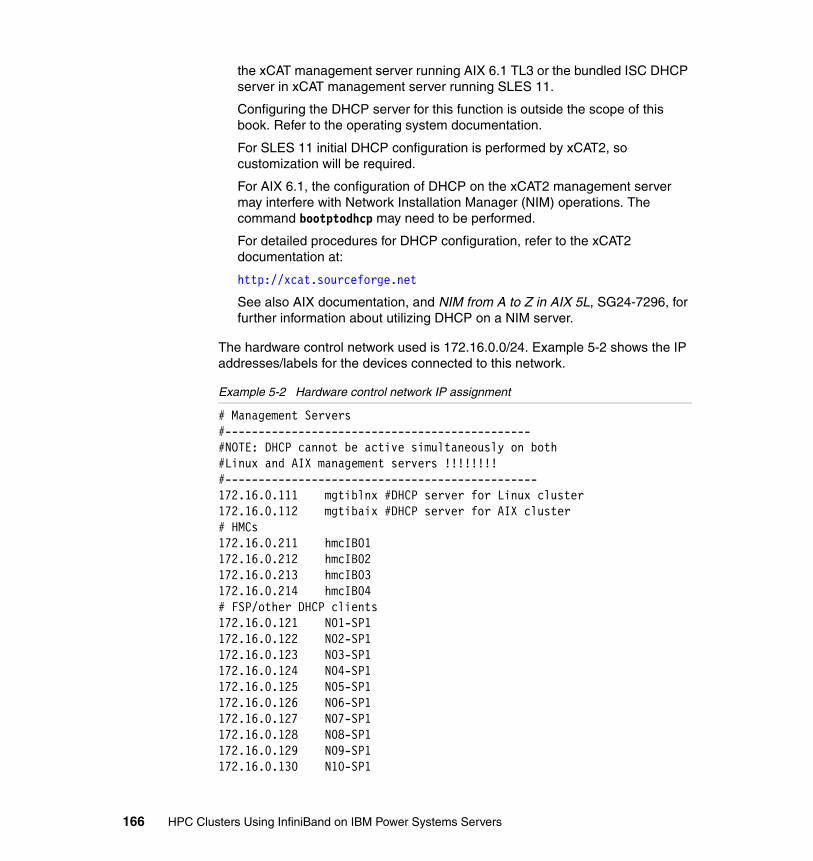
the xCAT management server running AIX 6.1 TL3 or the bundled ISC DHCP server in xCAT management server running SLES 11.
Configuring the DHCP server for this function is outside the scope of this book. Refer to the operating system documentation.
For SLES 11 initial DHCP configuration is performed by xCAT2, so customization will be required.
For AIX 6.1, the configuration of DHCP on the xCAT2 management server may interfere with Network Installation Manager (NIM) operations. The command bootptodhcp may need to be performed.
For detailed procedures for DHCP configuration, refer to the xCAT2 documentation at:
http://xcat.sourceforge.net
See also AIX documentation, and NIM from A to Z in AIX 5L, SG24-7296, for further information about utilizing DHCP on a NIM server.
The hardware control network used is 172.16.0.0/24. Example 5-2 shows the IP addresses/labels for the devices connected to this network.
Example 5-2 Hardware control network IP assignment
# Management Servers#----------------------------------------------#NOTE: DHCP cannot be active simultaneously on both#Linux and AIX management servers !!!!!!!!#-----------------------------------------------172.16.0.111 mgtiblnx #DHCP server for Linux cluster172.16.0.112 mgtibaix #DHCP server for AIX cluster# HMCs172.16.0.211 hmcIB01172.16.0.212 hmcIB02172.16.0.213 hmcIB03172.16.0.214 hmcIB04# FSP/other DHCP clients172.16.0.121 N01-SP1172.16.0.122 N02-SP1172.16.0.123 N03-SP1172.16.0.124 N04-SP1172.16.0.125 N05-SP1172.16.0.126 N06-SP1172.16.0.127 N07-SP1172.16.0.128 N08-SP1172.16.0.129 N09-SP1172.16.0.130 N10-SP1
166 HPC Clusters Using InfiniBand on IBM Power Systems Servers
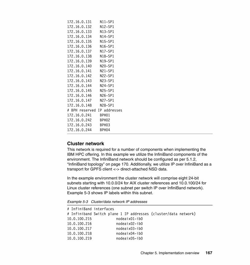
172.16.0.131 N11-SP1172.16.0.132 N12-SP1172.16.0.133 N13-SP1172.16.0.134 N14-SP1172.16.0.135 N15-SP1172.16.0.136 N16-SP1172.16.0.137 N17-SP1172.16.0.138 N18-SP1172.16.0.139 N19-SP1172.16.0.140 N20-SP1172.16.0.141 N21-SP1172.16.0.142 N22-SP1172.16.0.143 N23-SP1172.16.0.144 N24-SP1172.16.0.145 N25-SP1172.16.0.146 N26-SP1172.16.0.147 N27-SP1172.16.0.148 N28-SP1# BPH reserved IP addresses172.16.0.241 BPH01172.16.0.242 BPH02172.16.0.243 BPH03172.16.0.244 BPH04
Cluster network This network is required for a number of components when implementing the IBM HPC offering. In this example we utilize the InfiniBand components of the environment. The InfiniBand network should be configured as per 5.1.2, “InfiniBand topology” on page 170. Additionally, we utilize IP over InfiniBand as a transport for GPFS client <-> direct-attached NSD data.
In the example environment the cluster network will comprise eight 24-bit subnets starting with 10.0.0/24 for AIX cluster references and 10.0.100/24 for Linux cluster references (one subnet per switch IP over InfiniBand network). Example 5-3 shows IP labels within this subnet.
Example 5-3 Cluster/data network IP addresses
# InfiniBand interfaces# Infiniband Switch plane 1 IP addresses (cluster/data network)10.0.100.215 nodeaix01-ib010.0.100.216 nodeaix02-ib010.0.100.217 nodeaix03-ib010.0.100.218 nodeaix04-ib010.0.100.219 nodeaix05-ib0
Chapter 5. Implementation overview 167
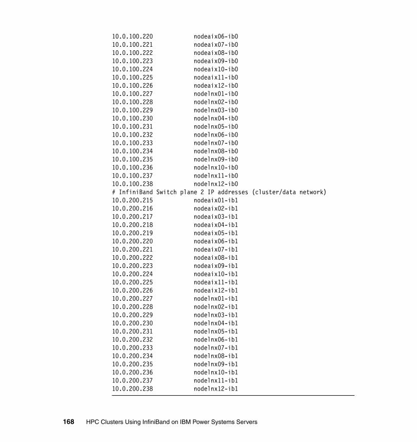
10.0.100.220 nodeaix06-ib010.0.100.221 nodeaix07-ib010.0.100.222 nodeaix08-ib010.0.100.223 nodeaix09-ib010.0.100.224 nodeaix10-ib010.0.100.225 nodeaix11-ib010.0.100.226 nodeaix12-ib010.0.100.227 nodelnx01-ib010.0.100.228 nodelnx02-ib010.0.100.229 nodelnx03-ib010.0.100.230 nodelnx04-ib010.0.100.231 nodelnx05-ib010.0.100.232 nodelnx06-ib010.0.100.233 nodelnx07-ib010.0.100.234 nodelnx08-ib010.0.100.235 nodelnx09-ib010.0.100.236 nodelnx10-ib010.0.100.237 nodelnx11-ib010.0.100.238 nodelnx12-ib0# InfiniBand Switch plane 2 IP addresses (cluster/data network)10.0.200.215 nodeaix01-ib110.0.200.216 nodeaix02-ib110.0.200.217 nodeaix03-ib110.0.200.218 nodeaix04-ib110.0.200.219 nodeaix05-ib110.0.200.220 nodeaix06-ib110.0.200.221 nodeaix07-ib110.0.200.222 nodeaix08-ib110.0.200.223 nodeaix09-ib110.0.200.224 nodeaix10-ib110.0.200.225 nodeaix11-ib110.0.200.226 nodeaix12-ib110.0.200.227 nodelnx01-ib110.0.200.228 nodelnx02-ib110.0.200.229 nodelnx03-ib110.0.200.230 nodelnx04-ib110.0.200.231 nodelnx05-ib110.0.200.232 nodelnx06-ib110.0.200.233 nodelnx07-ib110.0.200.234 nodelnx08-ib110.0.200.235 nodelnx09-ib110.0.200.236 nodelnx10-ib110.0.200.237 nodelnx11-ib110.0.200.238 nodelnx12-ib1
168 HPC Clusters Using InfiniBand on IBM Power Systems Servers
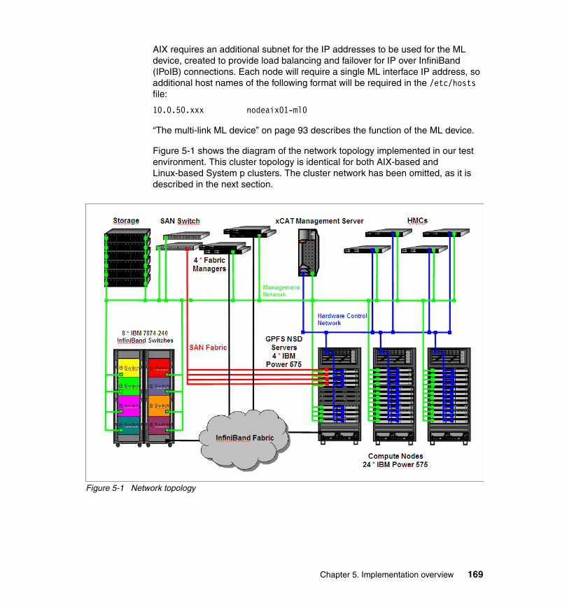
AIX requires an additional subnet for the IP addresses to be used for the ML device, created to provide load balancing and failover for IP over InfiniBand (IPoIB) connections. Each node will require a single ML interface IP address, so additional host names of the following format will be required in the /etc/hosts file:
10.0.50.xxx nodeaix01-ml0
“The multi-link ML device” on page 93 describes the function of the ML device.
Figure 5-1 shows the diagram of the network topology implemented in our test environment. This cluster topology is identical for both AIX-based and Linux-based System p clusters. The cluster network has been omitted, as it is described in the next section.
Figure 5-1 Network topology
Chapter 5. Implementation overview 169
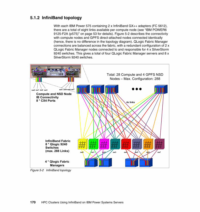
5.1.2 InfiniBand topology
With each IBM Power 575 containing 2 x InfiniBand GX++ adapters (FC 5612), there are a total of eight links available per compute node (see “IBM POWER6 9125-F2A (p575)” on page 53 for details). Figure 5-2 describes the connectivity with compute nodes and GPFS direct-attached nodes connected identically (hence, there is no difference in the topology diagram). QLogic Fabric Manager connections are balanced across the fabric, with a redundant configuration of 2 x QLogic Fabric Manager nodes connected to and responsible for 4 x SilverStorm 9240 switches. This gives a total of four QLogic Fabric Manager servers and 8 x SilverStorm 9240 switches.
Figure 5-2 InfiniBand topology
Total: 28 Compute and 4 GPFS NSD Nodes – Max. Configuration: 288
InfiniBand Fabric8 * Qlogic 9240 Switches(max. 288 Links)
Compute and NSD Node IB Connectivity8 * CX4 Ports 4x links
sw3
TOPPCI Card
TOPPCI Card
Left PCI Riser
Right PCI
Riser
GX+ Adapter GX+ Adapter
sw4 sw5 sw6 sw7sw0 sw1 sw2 sw3
sw6sw4sw2sw0
4 * Qlogic Fabric Managers
sw5sw1 sw7
170 HPC Clusters Using InfiniBand on IBM Power Systems Servers
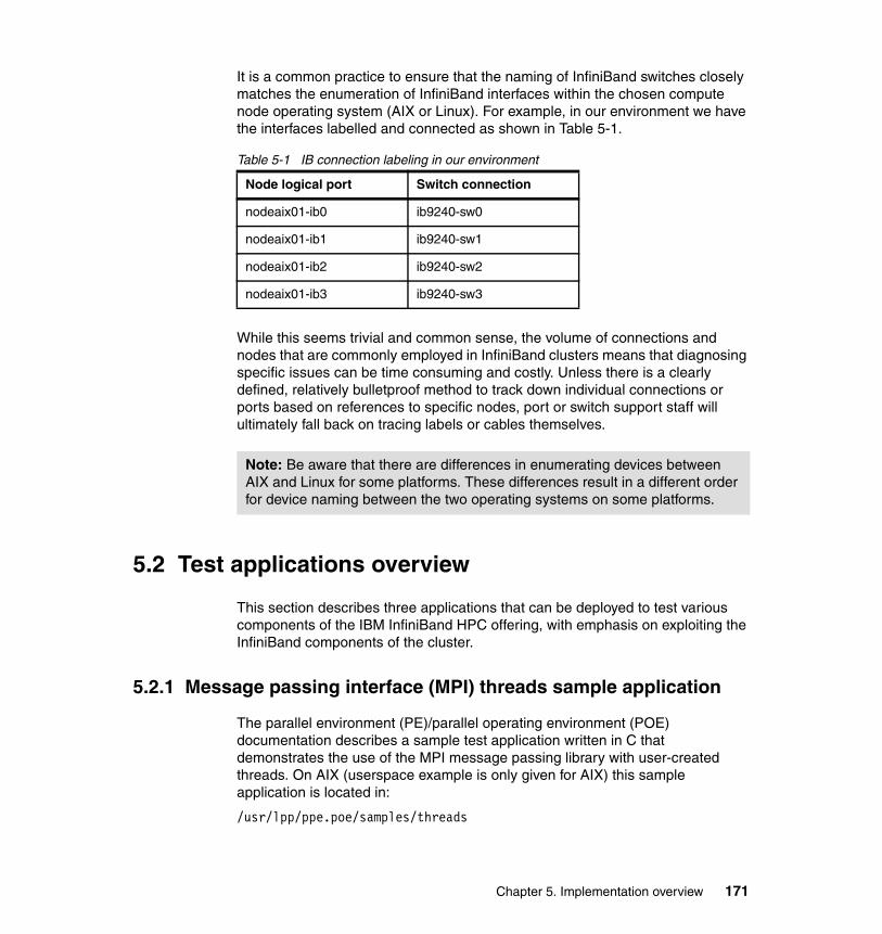
It is a common practice to ensure that the naming of InfiniBand switches closely matches the enumeration of InfiniBand interfaces within the chosen compute node operating system (AIX or Linux). For example, in our environment we have the interfaces labelled and connected as shown in Table 5-1.
Table 5-1 IB connection labeling in our environment
While this seems trivial and common sense, the volume of connections and nodes that are commonly employed in InfiniBand clusters means that diagnosing specific issues can be time consuming and costly. Unless there is a clearly defined, relatively bulletproof method to track down individual connections or ports based on references to specific nodes, port or switch support staff will ultimately fall back on tracing labels or cables themselves.
5.2 Test applications overview
This section describes three applications that can be deployed to test various components of the IBM InfiniBand HPC offering, with emphasis on exploiting the InfiniBand components of the cluster.
5.2.1 Message passing interface (MPI) threads sample application
The parallel environment (PE)/parallel operating environment (POE) documentation describes a sample test application written in C that demonstrates the use of the MPI message passing library with user-created threads. On AIX (userspace example is only given for AIX) this sample application is located in:
/usr/lpp/ppe.poe/samples/threads
Node logical port Switch connection
nodeaix01-ib0 ib9240-sw0
nodeaix01-ib1 ib9240-sw1
nodeaix01-ib2 ib9240-sw2
nodeaix01-ib3 ib9240-sw3
Note: Be aware that there are differences in enumerating devices between AIX and Linux for some platforms. These differences result in a different order for device naming between the two operating systems on some platforms.
Chapter 5. Implementation overview 171
This test allows the use of userspace or IP message passing that utilizes the InfiniBand fabric.
5.2.2 Bandwidth (BW) sample application
The PE/POE documentation describes a sample test application written in Fortran that performs a point-to-point bandwidth test. On AIX this sample application is located in:
/usr/lpp/ppe.poe/samples/poetest.bw
On Linux this sample application is located in:
/opt/ibmhpc/ppe.poe/samples/poetest.bw
This test allows the use of userspace or IP message passing. We will utilize userspace message passing to utilize the InfiniBand fabric.
5.2.3 CAST sample application
The PE/POE documentation describes a sample test application written in Fortran that broadcasts from one node to all other nodes in the cluster. On AIX this sample application is located in:
/usr/lpp/ppe.poe/samples/poetest.cast
On Linux this sample application is located in:
/opt/ibmhpc/ppe.poe/samples/poetest.cast
This test allows the use of userspace or IP message passing. We utilize userspace message passing to test the InfiniBand fabric.
5.3 Implementation summary
The following is a high-level list of the steps that were undertaken to install and configure our example InfiniBand on a POWER6 environment.
We assume that basic requirements, such as electrical power and cooling (including the IBM Power 575’s requirement for water cooling) are available, and that hardware components are unboxed and racked, tested, and found to be operating.
172 HPC Clusters Using InfiniBand on IBM Power Systems Servers
5.3.1 Prepare hardware
All of the hardware components involved in this environment must be prepared with the correct licensed internal code (LIC), microcode, firmware, or global firmware (GFW). The recommended code levels (used in this example environment) at the time of writing (and implemented in our example environment) are:
� IBM Power Hardware
HMC: V7R3.4.0 Service Pack 1 MH01163
� IBM Power 575
– Fix pack 01EPS330_078 for GFW– Fix pack 02EP330_078 for Power Subsystem Microcode
� Fabric hardware
QLogic Switch Firmware: SilverStorm 9000 Series Switch Firmware level 4.2.4.2.1
Full details of all current requirements specific to InfiniBand on IBM Power systems should be reviewed at:
http://www14.software.ibm.com/webapp/set2/sas/f/networkmanager/power6/codelevels.html
5.3.2 Configure environment
To configure the environment:
� Network (Ethernet) configuration
The logical configuration of your Ethernet network is outside the scope of this book. We assume that your environment is cabled and configured in a way that will allow all frames to be controlled via xCAT2 through their controlling HMC, as well as allow the xCAT2 management server the ability to install and control the compute nodes. The basic design of our environment is described in 5.1.1, “Network topology” on page 163.
� Storage configuration
The configuration of your storage is site dependant. Where available some sites might choose to utilize boot from SAN for compute nodes. However, in a large cluster this may be a prohibitive expense. Most sites will use the internal disks of the Power 575 nodes to create diskful nodes. Another alternative might be to create diskless clients using the procedures provided in the xCAT2 documentation available at:
http://xcat.sourceforge.net
Chapter 5. Implementation overview 173

The process to do this is also described in Configuring and Managing AIX Clusters Using xCAT 2, SG24-77666.
GPFS storage node configuration is dependant on your desired GPFS topology. In our example the configuration is:
– Diskful nodes booting from internal software-mirrored disks. This provides protection to node outage due to disk failure.
– Four direct-attached GPFS storage nodes utilizing SAN storage provided through the IBM 2109-M48 switches, IBM San Volume Controller, and IBM DS8300.
– Compute nodes running as GPFS clients and accessing required storage from the four dedicated GPFS direct-attached nodes. Data will be transferred between the direct-attached nodes and the clients utilizing IP over InfiniBand.
Further details of our implementation are described in Chapter 7, “Configuring InfiniBand on AIX” on page 205, and Chapter 8, “Configuring InfiniBand on Linux on Power” on page 235.
� InfiniBand switch fabric configuration
InfiniBand switch configuration is detailed in Chapter 6, “Configuring the InfiniBand fabric” on page 177, and is based on the topology outlined in Figure 5-2 on page 170. This procedure includes the installation and configuration of the QLogic Fabric Manager.
� xCAT2 installation
The installation of the xCAT2 Management server and post-install InfiniBand steps are described in Chapter 7, “Configuring InfiniBand on AIX” on page 205, and Chapter 8, “Configuring InfiniBand on Linux on Power” on page 235.
A rough overview of the installation steps is:
1. Installation and configuration of NTP
All devices should be configured to point to a common, redundant NTP infrastructure. In these examples we assume that this infrastructure is already in place.
2. Installation and configuration of xCAT2 on the xCAT2 management nodes
This includes the customization of any required post-install scripts or packages needed to configure InfiniBand, as well as various HPC stack products.
174 HPC Clusters Using InfiniBand on IBM Power Systems Servers
3. Deployment on cluster nodes using xCAT2
5.3.3 Deployment of the HPC stack
At the time of writing, the list of components from the IBM HPC stack that were installed was:
� Operating system
Installed during installation and configuration of xCAT2. Our example environment uses either AIX 6.1 TL3 or SLES 11.
� Compilers
– AIX 6.1 TL3
• XL C/C++ Enterprise Edition for AIX Level 10.1.0.0• Fortran Enterprise Edition for AIX 12.1.0.0• XL SMP Runtime Environment 1.8.0.0
– SLES 11
A full list of all RPM packages that provide compiler functionality on SLES 11 is provided in Chapter 8, “Configuring InfiniBand on Linux on Power” on page 235.
� InfiniBand Drivers
– AIX 6.1 TL3
None required, part of OS.
– SLES 11 (OFED): only required on compute nodes
A full list of all RPM packages that were installed on SLES 11 to provide full OFED support is provided in Chapter 8, “Configuring InfiniBand on Linux on Power” on page 235.
Chapter 5. Implementation overview 175
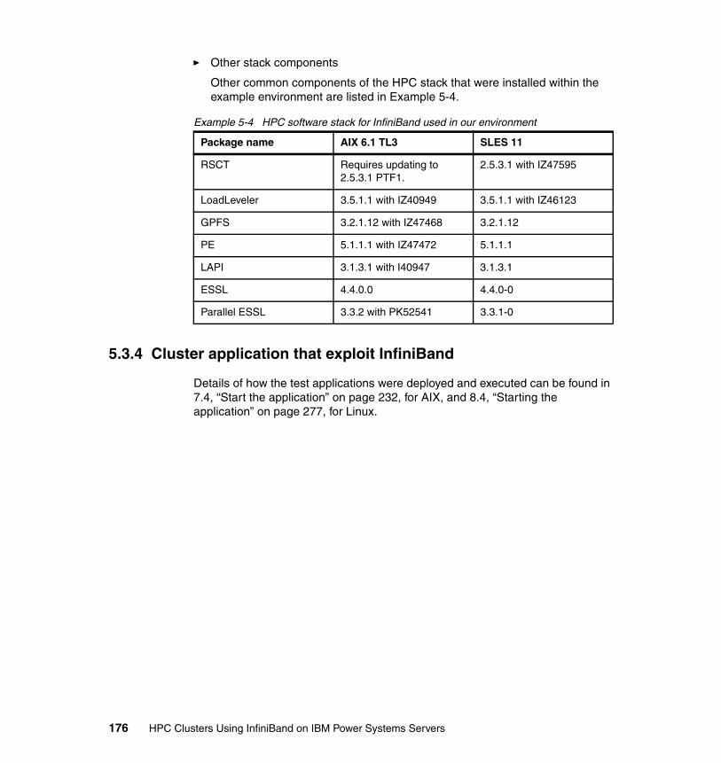
� Other stack components
Other common components of the HPC stack that were installed within the example environment are listed in Example 5-4.
Example 5-4 HPC software stack for InfiniBand used in our environment
5.3.4 Cluster application that exploit InfiniBand
Details of how the test applications were deployed and executed can be found in 7.4, “Start the application” on page 232, for AIX, and 8.4, “Starting the application” on page 277, for Linux.
Package name AIX 6.1 TL3 SLES 11
RSCT Requires updating to 2.5.3.1 PTF1.
2.5.3.1 with IZ47595
LoadLeveler 3.5.1.1 with IZ40949 3.5.1.1 with IZ46123
GPFS 3.2.1.12 with IZ47468 3.2.1.12
PE 5.1.1.1 with IZ47472 5.1.1.1
LAPI 3.1.3.1 with I40947 3.1.3.1
ESSL 4.4.0.0 4.4.0-0
Parallel ESSL 3.3.2 with PK52541 3.3.1-0
176 HPC Clusters Using InfiniBand on IBM Power Systems Servers
Chapter 6. Configuring the InfiniBand fabric
In this chapter we discuss the InfiniBand fabric installation and configuration. Our main focus is setting up the switches and integrating them with QLogic Fabric Manager. This chapter covers the following topics:
� Preparing the InfiniBand switches � Preparing the QLogic Fabric Manager systems � Verifying the fabric configuration
6
© Copyright IBM Corp. 2009. All rights reserved. 177

6.1 InfiniBand fabric setup description
In Chapter 5, “Implementation overview” on page 161, we introduce our test environment. The InfiniBand fabric that we used consists of eight IBM 7874-240 InfiniBand switches. Your configuration may be different, depending on cluster size, performance, and availability requirements. In this chapter we discuss the installation and configuration of a smaller number of switches and only two Fabric Manager servers in order to simplify the procedure.
Setting up an InfiniBand fabric environment requires a good understanding of all the terminology involved and planning in order to use the fabric in the most efficient way.
We assume that the following steps are already done:
� The servers and switches are installed in the rack and are powered on.
� The network management Ethernet cables for all InfiniBand switches are connected and QLogic Fabric Managers are installed with SuSe Enterprise Linux Server Version 10 SP2 x86_64.
� The InfiniBand cables are connected according to 5.1.1, “Network topology” on page 163.
� InfiniBand hardware has been checked and is free of errors before moving forward with the setup.
For more information about InfiniBand switches, refer to the product manuals at:
http://www.ibm.comhttp://www.qlogic.com
Naming convention All the names and their IP are described in the 5.1, “Environment description” on page 162.
Note: Some of the InfiniBand switches have four Ethernet ports. Ensure that all four Ethernet cables are connected as each managed spine has its own dedicated port.
178 HPC Clusters Using InfiniBand on IBM Power Systems Servers
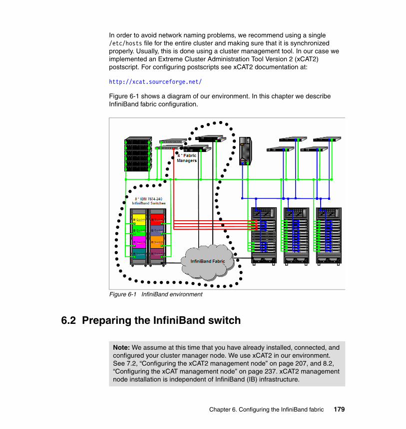
In order to avoid network naming problems, we recommend using a single /etc/hosts file for the entire cluster and making sure that it is synchronized properly. Usually, this is done using a cluster management tool. In our case we implemented an Extreme Cluster Administration Tool Version 2 (xCAT2) postscript. For configuring postscripts see xCAT2 documentation at:
http://xcat.sourceforge.net/
Figure 6-1 shows a diagram of our environment. In this chapter we describe InfiniBand fabric configuration.
Figure 6-1 InfiniBand environment
6.2 Preparing the InfiniBand switch
Note: We assume at this time that you have already installed, connected, and configured your cluster manager node. We use xCAT2 in our environment. See 7.2, “Configuring the xCAT2 management node” on page 207, and 8.2, “Configuring the xCAT management node” on page 237. xCAT2 management node installation is independent of InfiniBand (IB) infrastructure.
Chapter 6. Configuring the InfiniBand fabric 179
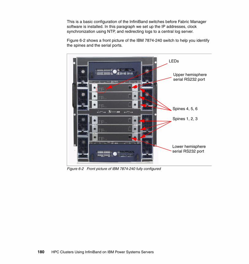
This is a basic configuration of the InfiniBand switches before Fabric Manager software is installed. In this paragraph we set up the IP addresses, clock synchronization using NTP, and redirecting logs to a central log server.
Figure 6-2 shows a front picture of the IBM 7874-240 switch to help you identify the spines and the serial ports.
Figure 6-2 Front picture of IBM 7874-240 fully configured
Spines 4, 5, 6
Spines 1, 2, 3
Upper hemisphereserial RS232 port
Lower hemisphereserial RS232 port
LEDs
180 HPC Clusters Using InfiniBand on IBM Power Systems Servers
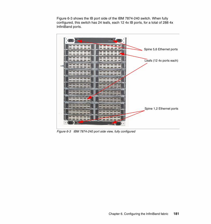
Figure 6-3 shows the IB port side of the IBM 7874-240 switch. When fully configured, this switch has 24 leafs, each 12 4x IB ports, for a total of 288 4x InfiniBand ports.
Figure 6-3 IBM 7874-240 port side view, fully configured
Leafs (12 4x ports each)
Spine 5,6 Ethernet ports
Spine 1,2 Ethernet ports
Chapter 6. Configuring the InfiniBand fabric 181
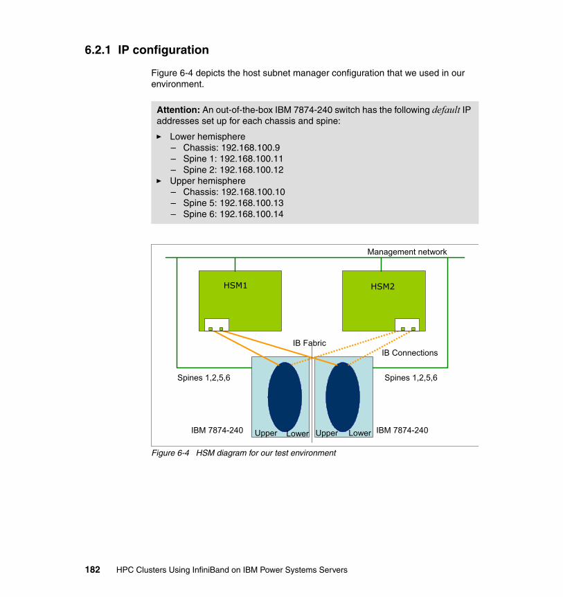
6.2.1 IP configuration
Figure 6-4 depicts the host subnet manager configuration that we used in our environment.
Figure 6-4 HSM diagram for our test environment
Attention: An out-of-the-box IBM 7874-240 switch has the following default IP addresses set up for each chassis and spine:
� Lower hemisphere– Chassis: 192.168.100.9– Spine 1: 192.168.100.11– Spine 2: 192.168.100.12
� Upper hemisphere– Chassis: 192.168.100.10– Spine 5: 192.168.100.13– Spine 6: 192.168.100.14
HSM1 HSM2
IBM 7874-240Upper Lower
IB Fabric
Management network
IB Connections
Spines 1,2,5,6 Spines 1,2,5,6
IBM 7874-240 Lower Upper
182 HPC Clusters Using InfiniBand on IBM Power Systems Servers

Example 6-1 lists the management IP addresses used for the InfiniBand switch and host subnet managers (HSMs) in our environment.
Example 6-1 Management IP addresses for HSMs
# Host Subnet Manager IP addresses192.168.100.241 fm01 qms01192.168.100.242 fm02 qms02
In order to set up the spine IP address, use the provided serial cables to connect to each spine. Use a serial terminal emulation of your choice (we used minicom running on a Linux box) with the following settings:
8 data bitsno parity bits1 stop bit57.6K baudUse VT100 emulation.Flow control = XON/XOFF
The following procedure describes setting up IP addresses for one hemisphere. Follow the same procedure for the second hemisphere.
1. Identify the master spine on one of the hemispheres. This is the spine with the green Act LED light lit (Figure 6-2 on page 180).
2. Plug the RJ11 serial cable into the port marked 'RS232' on the master spine.
3. Press Enter to get a prompt on the hyper terminal.
4. Enter the chassis IP address and default route for the chassis that you are currently connected to:
setChassisIpAddr -h <chassis IP number> -m <netmask>setDefaultRoute -h <Default route IP number>
5. Reboot the spine.
Notes: If you have multiple IB switches in your environment, defer connecting them to your management network until finalizing the IP configuration for each switch.
The diagram in Figure 6-4 on page 182 has been used in our test environment. Refer to your supplier recommendation for designing your HSM environment.
Note: You must break into the spine (space bar) as it is starting to come back up.
Chapter 6. Configuring the InfiniBand fabric 183

6. As the spine starts coming back up it will display the following 3-line prompt for 5 seconds:
Unified Boot Manager[1] image1[2] image2
You must press the spacebar within 5 seconds to stop the boot from continuing. Now issue 'reboot' to start the reboot and then press the spacebar when the prompt is displayed.
7. At the '[boot]:' prompt enter the spine IP address and gateway:
spineip <spine IP number> <default gateway IP number>
8. Issue 'reboot' to reboot the spine and this time let the spine come all the way up (do not break in at the prompt).
9. Let the reboot continue until the spine comes back online. Wait for the following line to be displayed:
Spine <X> online
Where <X> is the spine to which you are connected.
10.When we rebooted the spine the first time the slave-managed spine took over for the master. The Act LED light should now be on for the other spine. Move the RJ11 serial cable to that spine.
11.Repeat steps 6 through 9 to set the IP number for the other spine.
12.Repeat this entire process for the other hemisphere.
At this point the ssh command can be used for accessing the switch provided that you supply a password.
Failover and high availabilityThe 7874 switch has been designed for high availability and performance. In fact, the switch has been constructed by putting together (mirroring) two identical halves called hemispheres.
For a fully configured switch, the bandwidth is ensured by six spines (forming the switch backbone), three for each hemisphere.
Four out of the six spines are managed. Two of the spines in each hemisphere are managed and the third one (in each hemisphere) is unmanaged. One of the ways to identify a spine is to check the RS232 port. If it has the RS232 port, it is a managed spine. Without it, it is an unmanaged spine. Moreover, an
Note: The default user name is admin and the password is adminpass for InfiniBand switches.
184 HPC Clusters Using InfiniBand on IBM Power Systems Servers

unmanaged spine can go into any slots while the managed spine can only be installed into slots 1, 2, 5, and 6.
In each hemisphere the managed spines are implemented in a redundant configuration, the active spine being protected by a failover mechanism. Each managed spine has its own IP address. However, only one spine per hemisphere is active for managing the switch.
The active spine also carries the chassis IP address. There is one chassis IP address per hemisphere. This chassis IP address is floating. If the active spine fails, the chassis IP address will be moved to the other managed spine, which becomes active through the failover mechanism.
By default, spine 1 in the lower hemisphere and spine 6 in the upper hemisphere are the active ones. The chassis IP addresses are used for managing the switch through the Fabric Manager running on the Fabric Manager servers.
Switch descriptionBy default, each InfiniBand switch has an identifier in the form of a globally unique identifier (GUID) as the switch description, which is difficult to remember or use. We modified each switch description in order to fit our understanding of the InfiniBand structure by using the command setIBNodeDesc in switch CLI. This could be a keyword to group all your switches, such as a project name, or input the switch host name if there is a common wildcard that could be used as the focus for future commands that use this as a filter.
We recommend enabling the concise name format and using an IB node desc that matches the TCP/IP name given to the chassis hemisphere in /etc/hosts.
Note: The Fast Fabric Chassis Setup Wizard in InfiniBand Fabric Suite (IFS) 4.3 also permits easier configuration of switches (IB node desc, NTP, timezone, syslog, log format, MTU, and so on).
Chapter 6. Configuring the InfiniBand fabric 185
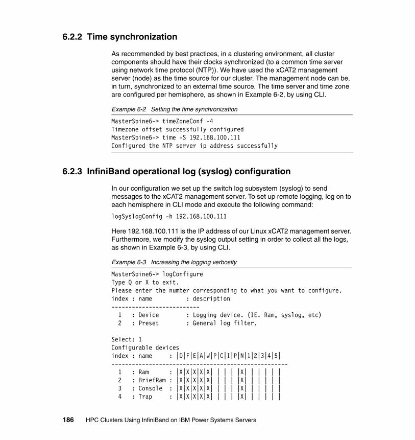
6.2.2 Time synchronization
As recommended by best practices, in a clustering environment, all cluster components should have their clocks synchronized (to a common time server using network time protocol (NTP)). We have used the xCAT2 management server (node) as the time source for our cluster. The management node can be, in turn, synchronized to an external time source. The time server and time zone are configured per hemisphere, as shown in Example 6-2, by using CLI.
Example 6-2 Setting the time synchronization
MasterSpine6-> timeZoneConf -4Timezone offset successfully configuredMasterSpine6-> time -S 192.168.100.111Configured the NTP server ip address successfully
6.2.3 InfiniBand operational log (syslog) configuration
In our configuration we set up the switch log subsystem (syslog) to send messages to the xCAT2 management server. To set up remote logging, log on to each hemisphere in CLI mode and execute the following command:
logSyslogConfig -h 192.168.100.111
Here 192.168.100.111 is the IP address of our Linux xCAT2 management server. Furthermore, we modify the syslog output setting in order to collect all the logs, as shown in Example 6-3, by using CLI.
Example 6-3 Increasing the logging verbosity
MasterSpine6-> logConfigureType Q or X to exit.Please enter the number corresponding to what you want to configure.index : name : description-------------------------- 1 : Device : Logging device. (IE. Ram, syslog, etc) 2 : Preset : General log filter.
Select: 1Configurable devicesindex : name : |D|F|E|A|W|P|C|I|P|N|1|2|3|4|5|---------------------------------------------------- 1 : Ram : |X|X|X|X|X| | | | |X| | | | | | 2 : BriefRam : |X|X|X|X|X| | | | |X| | | | | | 3 : Console : |X|X|X|X|X| | | | |X| | | | | | 4 : Trap : |X|X|X|X|X| | | | |X| | | | | |
186 HPC Clusters Using InfiniBand on IBM Power Systems Servers
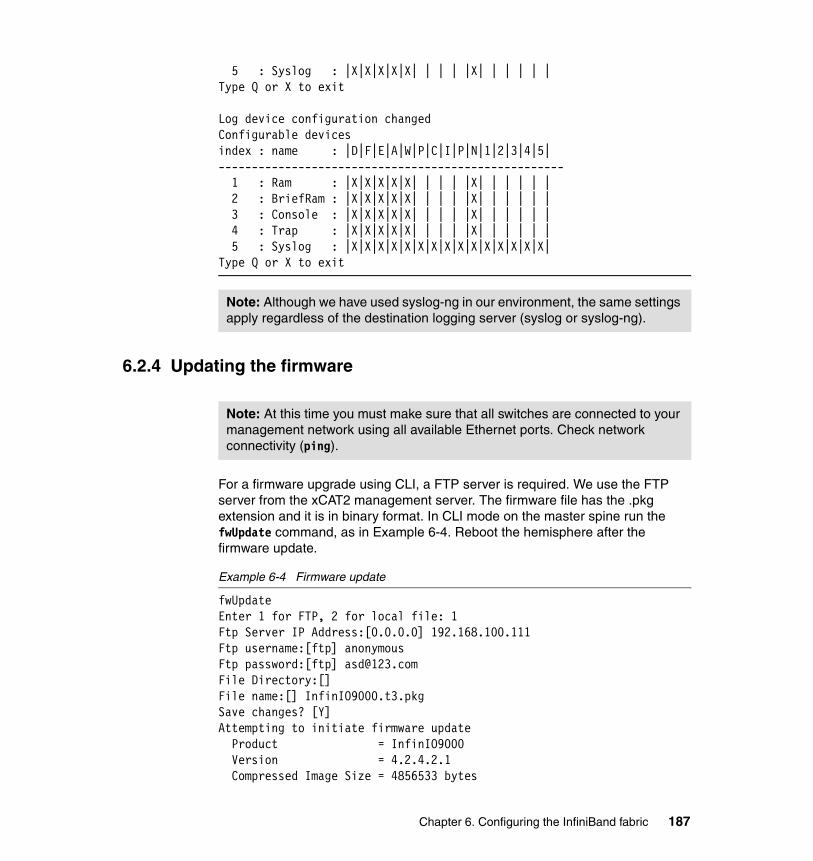
5 : Syslog : |X|X|X|X|X| | | | |X| | | | | |Type Q or X to exit
Log device configuration changedConfigurable devicesindex : name : |D|F|E|A|W|P|C|I|P|N|1|2|3|4|5|---------------------------------------------------- 1 : Ram : |X|X|X|X|X| | | | |X| | | | | | 2 : BriefRam : |X|X|X|X|X| | | | |X| | | | | | 3 : Console : |X|X|X|X|X| | | | |X| | | | | | 4 : Trap : |X|X|X|X|X| | | | |X| | | | | | 5 : Syslog : |X|X|X|X|X|X|X|X|X|X|X|X|X|X|X|Type Q or X to exit
6.2.4 Updating the firmware
For a firmware upgrade using CLI, a FTP server is required. We use the FTP server from the xCAT2 management server. The firmware file has the .pkg extension and it is in binary format. In CLI mode on the master spine run the fwUpdate command, as in Example 6-4. Reboot the hemisphere after the firmware update.
Example 6-4 Firmware update
fwUpdateEnter 1 for FTP, 2 for local file: 1Ftp Server IP Address:[0.0.0.0] 192.168.100.111Ftp username:[ftp] anonymousFtp password:[ftp] [email protected] Directory:[]File name:[] InfinIO9000.t3.pkgSave changes? [Y]Attempting to initiate firmware update Product = InfinIO9000 Version = 4.2.4.2.1 Compressed Image Size = 4856533 bytes
Note: Although we have used syslog-ng in our environment, the same settings apply regardless of the destination logging server (syslog or syslog-ng).
Note: At this time you must make sure that all switches are connected to your management network using all available Ethernet ports. Check network connectivity (ping).
Chapter 6. Configuring the InfiniBand fabric 187
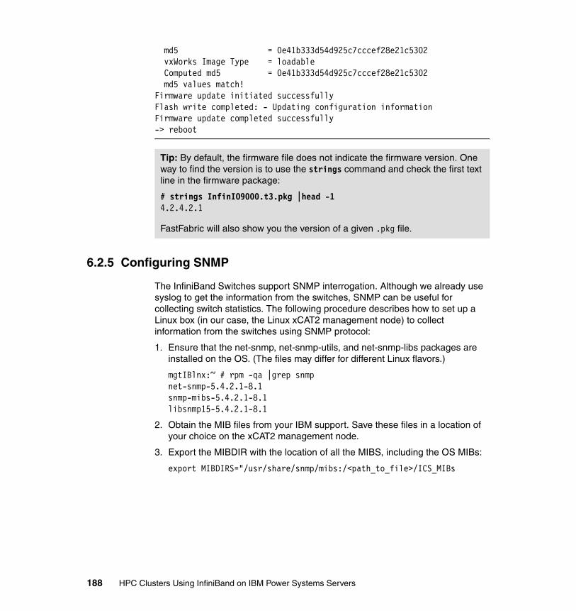
md5 = 0e41b333d54d925c7cccef28e21c5302 vxWorks Image Type = loadable Computed md5 = 0e41b333d54d925c7cccef28e21c5302 md5 values match!Firmware update initiated successfullyFlash write completed: - Updating configuration informationFirmware update completed successfully-> reboot
6.2.5 Configuring SNMP
The InfiniBand Switches support SNMP interrogation. Although we already use syslog to get the information from the switches, SNMP can be useful for collecting switch statistics. The following procedure describes how to set up a Linux box (in our case, the Linux xCAT2 management node) to collect information from the switches using SNMP protocol:
1. Ensure that the net-snmp, net-snmp-utils, and net-snmp-libs packages are installed on the OS. (The files may differ for different Linux flavors.)
mgtIBlnx:~ # rpm -qa |grep snmpnet-snmp-5.4.2.1-8.1snmp-mibs-5.4.2.1-8.1libsnmp15-5.4.2.1-8.1
2. Obtain the MIB files from your IBM support. Save these files in a location of your choice on the xCAT2 management node.
3. Export the MIBDIR with the location of all the MIBS, including the OS MIBs:
export MIBDIRS="/usr/share/snmp/mibs:/<path_to_file>/ICS_MIBs
Tip: By default, the firmware file does not indicate the firmware version. One way to find the version is to use the strings command and check the first text line in the firmware package:
# strings InfinIO9000.t3.pkg |head -14.2.4.2.1
FastFabric will also show you the version of a given .pkg file.
188 HPC Clusters Using InfiniBand on IBM Power Systems Servers

4. Run the snmpwalk command as in Example 6-5.
Example 6-5 SNMP sample
#snmpwalk -v1 -c public <IP> SNMPv2-SMI::enterprises.10222.2.1.1.1.0SNMPv2-SMI::enterprises.10222.2.1.1.1.0 = STRING: "SilverStorm 9240 - Firmware Version: 4.2.4.2.1, Mar 2 2009"
6.2.6 Configuring SSH
The InfiniBand switches have the possibility to import SSH keys from remote systems, so any system using ssh can execute commands without being prompted for a password. The sshKey command provided in the IB switch CLI can list, add, and remove SSH keys.
In an HPC environment, where the number of InfiniBand switches may be large, issuing commands to all the switches at the same time is an important feature. In the following sequence we describe how to set the xCAT2 management node to log in and execute commands to an hemisphere without being prompted for a password. The commands are listed in Example 6-6 and Example 6-7 on page 190 for one hemisphere. The same procedure applies to all switches.
1. Log on to your xCAT2 management node and generate the SSH keys on the xCAT2 management server using ssh-keygen command, if not already done. List the keys (cat ~/.ssh/id_rsa.pub, as shown in Example 6-6).
Example 6-6 Root’s public SSH key on the xCAT2 management server
mgtIBlnx:~ # cat ~/.ssh/id_rsa.pubssh-rsa AAAAB3NzaC1yc2EAAAABIwAAAQEAt11dVW+gVuNsO5mVEezKr2moYRuPE8OVe3g61bthrhrRadlDI22nRMdtN5X5xXDRXSbfyaRrDaT7seRrHm5QxD6GngzkSj0Wf7eT+I+BngGB+jM6CZTNymQ+UYmSDe42azPv+SzomFdpolGiNXYTnoizNZS3lVwIriNTCysoOIv6P48h9VbtV3M1eVCD93llO8T1plFhp8TjNF1vsiWxrhTZjCHb83MxXt6cpgVS+NaHpID84ESqk7lhkDZKEPOqFTTrI2WaM5Bl+B/pjwGH/G774+pCY8lQuUMK9W/PVzgdoBL9HMrqEh8OGZZhdHhH6vd2gXTp9kJFL/C95FZ/+w== root@mgtIBlnx
2. Log in on master spine and run the sshKey add “Key” command, where Key is the SSH key string from the file .ssh/id_rsa.pub.
Chapter 6. Configuring the InfiniBand fabric 189
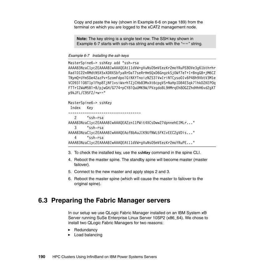
Copy and paste the key (shown in Example 6-6 on page 189) from the terminal on which you are logged to the xCAT2 management node.
Example 6-7 Installing the ssh keys
MasterSpine6-> sshKey add "ssh-rsa AAAAB3NzaC1yc2EAAAABIwAAAQEAt11dVW+gVuNsO5mVEezKr2moYRuPE8OVe3g61bthrhrRadlDI22nRMdtN5X5xXDRXSbfyaRrDaT7seRrHm5QxD6GngzkSj0Wf7eT+I+BngGB+jM6CZTNymQ+UYmSDe42azPv+SzomFdpolGiNXYTnoizNZS3lVwIriNTCysoOIv6P48h9VbtV3M1eVCD93llO8T1plFhp8TjNF1vsiWxrhTZjCHb83MxXt6cpgVS+NaHpID84ESqk7lhkDZKEPOqFTTrI2WaM5Bl+B/pjwGH/G774+pCY8lQuUMK9W/PVzgdoBL9HMrqEh8OGZZhdHhH6vd2gXTp9kJFL/C95FZ/+w=="
MasterSpine6-> sshKey Index Key----------------------------------- 2 "ssh-rsa AAAAB3NzaC1yc2EAAAABIwAAAQEA2zn11PWit4XCsDww27dpnnehEIMLr..." 3 "ssh-rsa AAAAB3NzaC1yc2EAAAABIwAAAQEAofBbAuJIK9UfNWL5FKIvEEC2gVDis..." 4 "ssh-rsa AAAAB3NzaC1yc2EAAAABIwAAAQEAt11dVW+gVuNsO5mVEezKr2moYRuPE..."
3. To check the installed key, use the sshKey command in the spine CLI.
4. Reboot the master spine. The standby spine will become master (master failover).
5. Connect to the new master and apply steps 2 and 3.
6. Reboot the master spine (which will cause the master to failover to the original spine).
6.3 Preparing the Fabric Manager servers
In our setup we use QLogic Fabric Manager installed on an IBM System x® Server running SuSe Enterprise Linux Server 10SP2 (x86_64). We chose to install two QLogic Fabric Managers for two reasons:
� Redundancy � Load balancing
Note: The key string is a single text row. The SSH key shown in Example 6-7 starts with ssh-rsa string and ends with the “==” string.
190 HPC Clusters Using InfiniBand on IBM Power Systems Servers

The QLogic Fabric Managers should not be used for any other tasks. The only purpose for QLogic Fabric Managers is to manage the fabric.
We limit the installation to only two QLogic Fabric Managers for demonstration purposes.
6.3.1 Installing the operating system
Perform the following preliminary steps for the QLogic Fabric Manager installation:
� Configure management network (Ethernet) VLANs (if necessary).
� Make sure that the PCIe InfiniBand adapters are installed in the server.
� If desired and available, configure a RAID controller for disk redundancy.
� Update the server firmware (if available).
� Install SuSe Enterprise Linux Server Version 10 SP2 for x86_64 on all QLogic Fabric Managers. Perform basic software installation of SLES 10SP2 and set up the IP configuration.
NTP configuration Set up the NTP configuration in order to have consistent syslog information across all systems including QLogic Fabric Managers. Edit the /etc/ntp.conf file and add the NTP server, as in Example 6-8. In our case, the NTP server is the xCAT2 management node.
Example 6-8 NTP configuration
server 192.168.100.111driftfile /var/lib/ntp/driftdisable authrestrict 127.0.0.1
Make sure that the NTP service is started at boot time (chkconfig ntp on):
# chkconfig --list|grep ntpntp 0:off 1:off 2:off 3:on 4:off 5:on 6:off
Important: As the Fabric Manager software has specific package-level requirements, we recommend turning off the OS automatic package update tool.
Chapter 6. Configuring the InfiniBand fabric 191
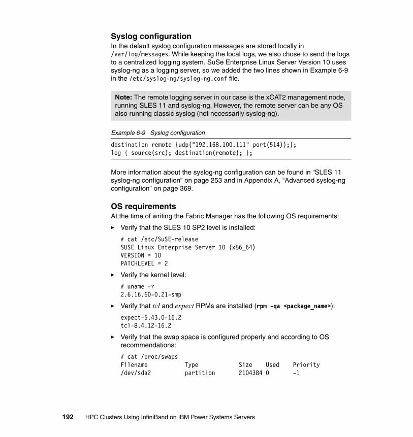
Syslog configurationIn the default syslog configuration messages are stored locally in /var/log/messages. While keeping the local logs, we also chose to send the logs to a centralized logging system. SuSe Enterprise Linux Server Version 10 uses syslog-ng as a logging server, so we added the two lines shown in Example 6-9 in the /etc/syslog-ng/syslog-ng.conf file.
Example 6-9 Syslog configuration
destination remote {udp("192.168.100.111" port(514));};log { source(src); destination(remote); };
More information about the syslog-ng configuration can be found in “SLES 11 syslog-ng configuration” on page 253 and in Appendix A, “Advanced syslog-ng configuration” on page 369.
OS requirementsAt the time of writing the Fabric Manager has the following OS requirements:
� Verify that the SLES 10 SP2 level is installed:
# cat /etc/SuSE-releaseSUSE Linux Enterprise Server 10 (x86_64)VERSION = 10PATCHLEVEL = 2
� Verify the kernel level:
# uname -r2.6.16.60-0.21-smp
� Verify that tcl and expect RPMs are installed (rpm -qa <package_name>):
expect-5.43.0-16.2tcl-8.4.12-16.2
� Verify that the swap space is configured properly and according to OS recommendations:
# cat /proc/swapsFilename Type Size Used Priority/dev/sda2 partition 2104384 0 -1
Note: The remote logging server in our case is the xCAT2 management node, running SLES 11 and syslog-ng. However, the remote server can be any OS also running classic syslog (not necessarily syslog-ng).
192 HPC Clusters Using InfiniBand on IBM Power Systems Servers
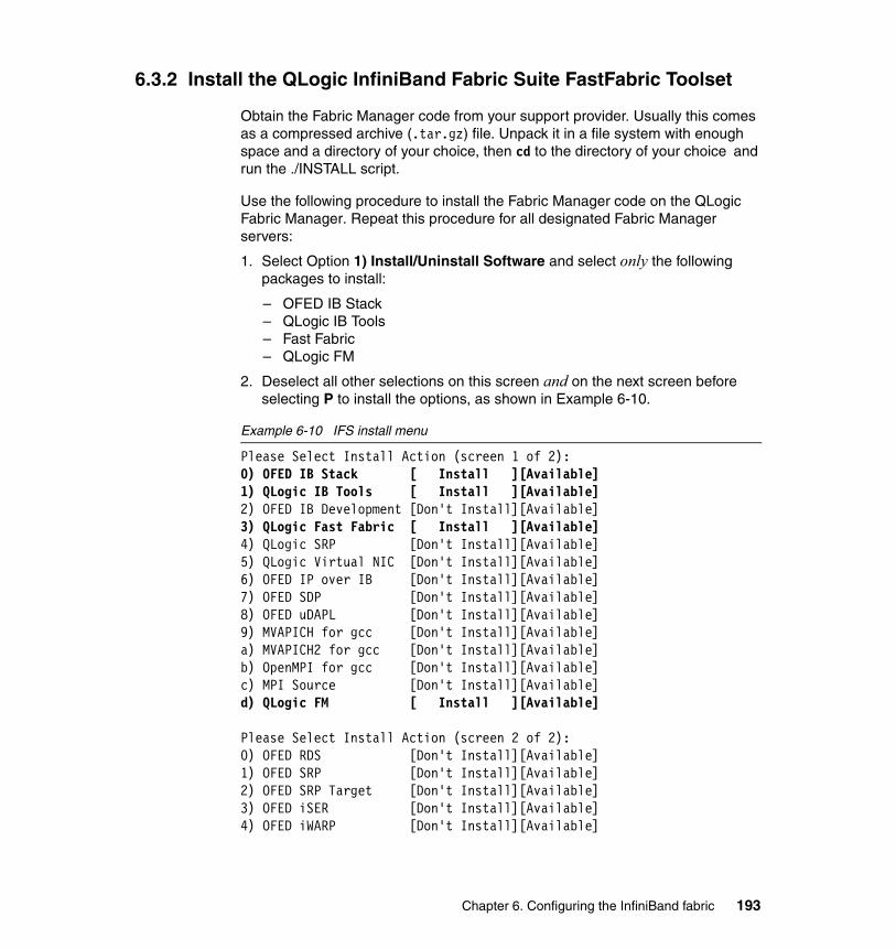
6.3.2 Install the QLogic InfiniBand Fabric Suite FastFabric Toolset
Obtain the Fabric Manager code from your support provider. Usually this comes as a compressed archive (.tar.gz) file. Unpack it in a file system with enough space and a directory of your choice, then cd to the directory of your choice and run the ./INSTALL script.
Use the following procedure to install the Fabric Manager code on the QLogic Fabric Manager. Repeat this procedure for all designated Fabric Manager servers:
1. Select Option 1) Install/Uninstall Software and select only the following packages to install:
– OFED IB Stack– QLogic IB Tools– Fast Fabric– QLogic FM
2. Deselect all other selections on this screen and on the next screen before selecting P to install the options, as shown in Example 6-10.
Example 6-10 IFS install menu
Please Select Install Action (screen 1 of 2):0) OFED IB Stack [ Install ][Available] 1) QLogic IB Tools [ Install ][Available] 2) OFED IB Development [Don't Install][Available] 3) QLogic Fast Fabric [ Install ][Available] 4) QLogic SRP [Don't Install][Available] 5) QLogic Virtual NIC [Don't Install][Available] 6) OFED IP over IB [Don't Install][Available] 7) OFED SDP [Don't Install][Available] 8) OFED uDAPL [Don't Install][Available] 9) MVAPICH for gcc [Don't Install][Available] a) MVAPICH2 for gcc [Don't Install][Available] b) OpenMPI for gcc [Don't Install][Available] c) MPI Source [Don't Install][Available] d) QLogic FM [ Install ][Available]
Please Select Install Action (screen 2 of 2):0) OFED RDS [Don't Install][Available] 1) OFED SRP [Don't Install][Available] 2) OFED SRP Target [Don't Install][Available] 3) OFED iSER [Don't Install][Available] 4) OFED iWARP [Don't Install][Available]
Chapter 6. Configuring the InfiniBand fabric 193

5) OFED Open SM [Don't Install][Available] 6) OFED Debug Info [Don't Install][Not Avail]
3. Once these packages are selected, select P to perform the installation. Accept the defaults option when queried during the install process (see Example 6-11).
Example 6-11 Default settings
Rebuild OFED SRPMs (a=all, p=prompt per SRPM, n=only as needed?) [n]:Enable OFED IB Stack (openibd) to autostart? [y]:Enable IB Port Monitor (iba_mon) to autostart? [y]:Enable QLogic FM (iview_fm) to autostart? [y]:Enable QLogic FM SNMP Agent (iview_snmpd) to autostart? [y]:
4. Reboot the hosts.
After the QLogic Fabric Manager is installed, verify that the packages are installed properly by running iba_config command and selecting the Show Installed Software option. The output of the iba_config command is shown in Example 6-12.
Example 6-12 iba_config command output
QLogic Inc. IB Installed Software (4.3.2.1.1)
OFED IB Stack [ Installed ] 1.3.1.0.4 QLogic IB Tools [ Installed ] 4.3.2.1.1 OFED IB Development [Not Installed] QLogic Fast Fabric [ Installed ] 4.3.2.1.1 QLogic SRP [Not Installed] QLogic Virtual NIC [Not Installed] OFED IP over IB [Not Installed] OFED SDP [Not Installed] OFED uDAPL [Not Installed] MVAPICH for gcc [Not Installed] MVAPICH2 for gcc [Not Installed] OpenMPI for gcc [Not Installed] MPI Source [Not Installed] QLogic FM [ Installed ] 4.3.2.1.1 OFED RDS [Not Installed] OFED SRP [Not Installed] OFED SRP Target [Not Installed] OFED iSER [Not Installed] OFED iWARP [Not Installed]
194 HPC Clusters Using InfiniBand on IBM Power Systems Servers

OFED Open SM [Not Installed] OFED Debug Info [Not Installed]
6.3.3 Fast fabric configuration
The fastfabric command can be used to configure the InfiniBand fabric. It has a text user interface (TUI) for setting up all necessary configuration files. In order to understand the minimal steps to start the InfiniBand fabric, we describe each step separately:
1. Set up the chassis IP addresses by adding them in the file /etc/syconfig/iba/chassis.
2. Set up the QLogic Fabric Manager IP addresses in the file /etc/sysconfig/iba/hosts.
3. Set up the InfiniBand ports on the QLogic Fabric Manager in the file /etc/sysconfig/iba/ports. This file contains a list of InfiniBand ports, where the syntax is hca:port and space delimited. In our case, the number of the adapter and port start with 1, as shown in Example 6-13.
Example 6-13 /etc/sysconfig/iba/ports file
# This file defines the local HCA ports to use to access the fabric(s)# specify one line per HCA port of the form hca:port such as:# 0:0 = 1st active port in system# 0:y = port y within system# x:0 = 1st active port on HCA x# x:y = HCA x, port y# The first HCA in the system is 1. The first port on an HCA is 1.1:1 1:2
4. Modify the error counters to a minimum value in /etc/sysconfig/iba/iba_mon.conf, as shown in Example 6-14. We recommend setting the values to 1 during the initial phase of configuring the InfiniBand switches and fabric. When all the settings are stable and ready for production the values can be modified as desired.
Example 6-14 /etc/sysconfig/iba/iba_mon.conf file
SymbolErrorCounter 1LinkErrorRecoveryCounter 1
Note: For steps 1 and 2 IP labels can be also used, but make sure that IP name resolution is configured and operational.
Chapter 6. Configuring the InfiniBand fabric 195
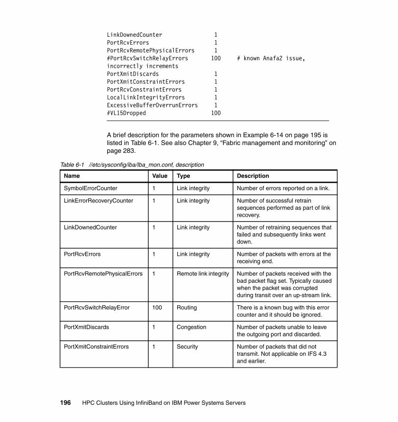
LinkDownedCounter 1PortRcvErrors 1PortRcvRemotePhysicalErrors 1#PortRcvSwitchRelayErrors 100 # known Anafa2 issue, incorrectly incrementsPortXmitDiscards 1PortXmitConstraintErrors 1PortRcvConstraintErrors 1LocalLinkIntegrityErrors 1ExcessiveBufferOverrunErrors 1#VL15Dropped 100
A brief description for the parameters shown in Example 6-14 on page 195 is listed in Table 6-1. See also Chapter 9, “Fabric management and monitoring” on page 283.
Table 6-1 //etc/sysconfig/iba/Iba_mon.conf, description
Name Value Type Description
SymbolErrorCounter 1 Link integrity Number of errors reported on a link.
LinkErrorRecoveryCounter 1 Link integrity Number of successful retrain sequences performed as part of link recovery.
LinkDownedCounter 1 Link integrity Number of retraining sequences that failed and subsequently links went down.
PortRcvErrors 1 Link integrity Number of packets with errors at the receiving end.
PortRcvRemotePhysicalErrors 1 Remote link integrity Number of packets received with the bad packet flag set. Typically caused when the packet was corrupted during transit over an up-stream link.
PortRcvSwitchRelayError 100 Routing There is a known bug with this error counter and it should be ignored.
PortXmitDiscards 1 Congestion Number of packets unable to leave the outgoing port and discarded.
PortXmitConstraintErrors 1 Security Number of packets that did not transmit. Not applicable on IFS 4.3 and earlier.
196 HPC Clusters Using InfiniBand on IBM Power Systems Servers
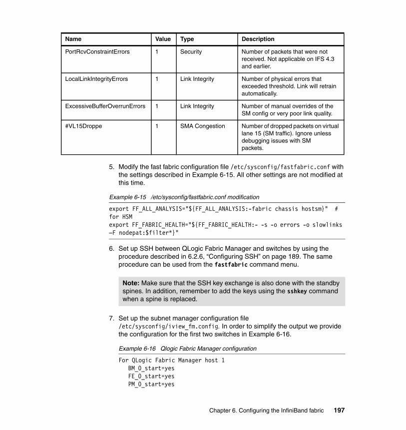
5. Modify the fast fabric configuration file /etc/sysconfig/fastfabric.conf with the settings described in Example 6-15. All other settings are not modified at this time.
Example 6-15 /etc/sysconfig/fastfabric.conf modification
export FF_ALL_ANALYSIS="${FF_ALL_ANALYSIS:-fabric chassis hostsm}" # for HSMexport FF_FABRIC_HEALTH="${FF_FABRIC_HEALTH:- -s -o errors -o slowlinks –F nodepat:$filter*}"
6. Set up SSH between QLogic Fabric Manager and switches by using the procedure described in 6.2.6, “Configuring SSH” on page 189. The same procedure can be used from the fastfabric command menu.
7. Set up the subnet manager configuration file /etc/sysconfig/iview_fm.config. In order to simplify the output we provide the configuration for the first two switches in Example 6-16.
Example 6-16 Qlogic Fabric Manager configuration
For QLogic Fabric Manager host 1 BM_0_start=yesFE_0_start=yesPM_0_start=yes
PortRcvConstraintErrors 1 Security Number of packets that were not received. Not applicable on IFS 4.3 and earlier.
LocalLinkIntegrityErrors 1 Link Integrity Number of physical errors that exceeded threshold. Link will retrain automatically.
ExcessiveBufferOverrunErrors 1 Link Integrity Number of manual overrides of the SM config or very poor link quality.
#VL15Droppe 1 SMA Congestion Number of dropped packets on virtual lane 15 (SM traffic). Ignore unless debugging issues with SMpackets.
Name Value Type Description
Note: Make sure that the SSH key exchange is also done with the standby spines. In addition, remember to add the keys using the sshkey command when a spine is replaced.
Chapter 6. Configuring the InfiniBand fabric 197
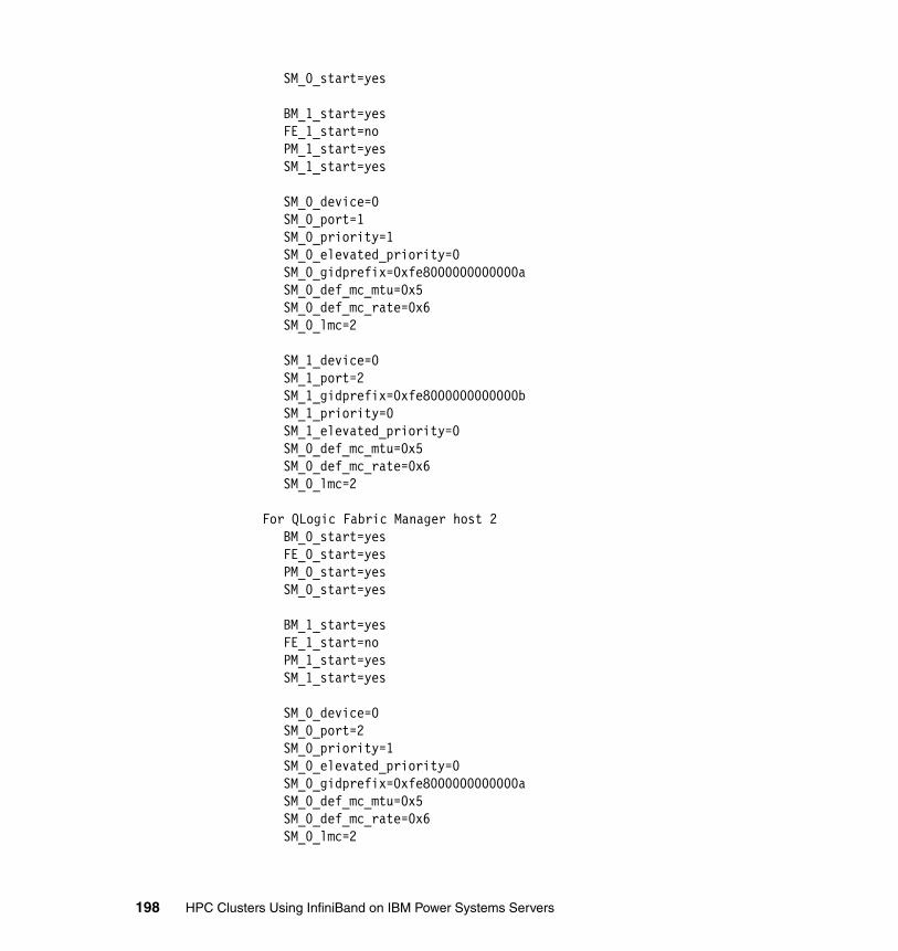
SM_0_start=yes
BM_1_start=yesFE_1_start=noPM_1_start=yesSM_1_start=yes
SM_0_device=0SM_0_port=1SM_0_priority=1SM_0_elevated_priority=0SM_0_gidprefix=0xfe8000000000000aSM_0_def_mc_mtu=0x5SM_0_def_mc_rate=0x6SM_0_lmc=2
SM_1_device=0SM_1_port=2SM_1_gidprefix=0xfe8000000000000bSM_1_priority=0SM_1_elevated_priority=0SM_0_def_mc_mtu=0x5SM_0_def_mc_rate=0x6SM_0_lmc=2
For QLogic Fabric Manager host 2BM_0_start=yesFE_0_start=yesPM_0_start=yesSM_0_start=yes
BM_1_start=yesFE_1_start=noPM_1_start=yesSM_1_start=yes
SM_0_device=0SM_0_port=2SM_0_priority=1SM_0_elevated_priority=0SM_0_gidprefix=0xfe8000000000000aSM_0_def_mc_mtu=0x5SM_0_def_mc_rate=0x6SM_0_lmc=2
198 HPC Clusters Using InfiniBand on IBM Power Systems Servers
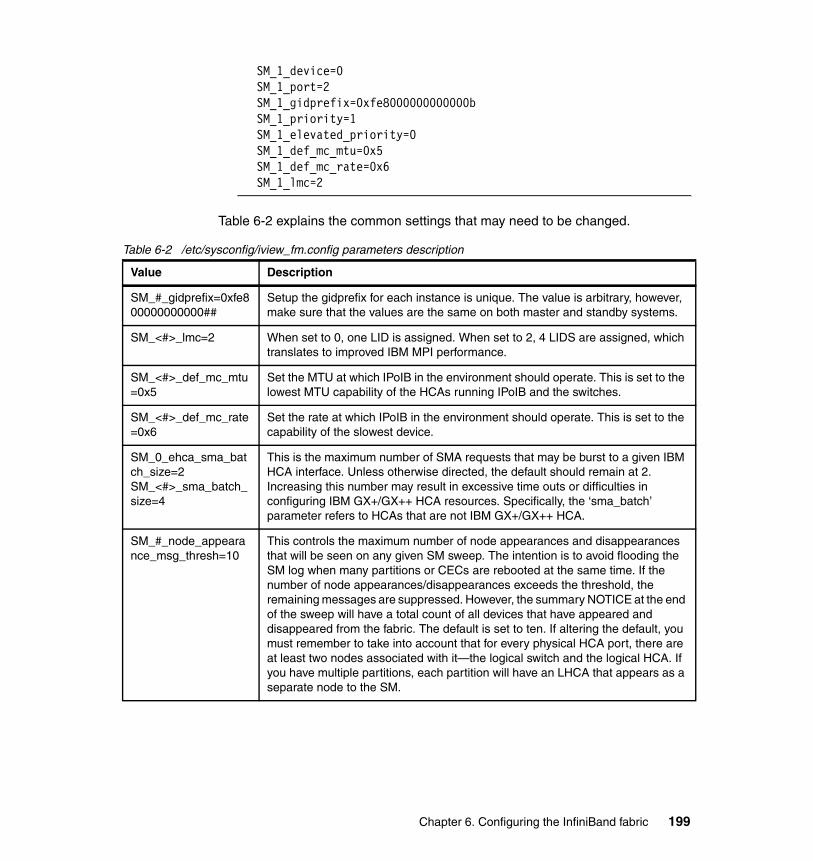
SM_1_device=0SM_1_port=2SM_1_gidprefix=0xfe8000000000000bSM_1_priority=1SM_1_elevated_priority=0SM_1_def_mc_mtu=0x5SM_1_def_mc_rate=0x6SM_1_lmc=2
Table 6-2 explains the common settings that may need to be changed.
Table 6-2 /etc/sysconfig/iview_fm.config parameters description
Value Description
SM_#_gidprefix=0xfe800000000000##
Setup the gidprefix for each instance is unique. The value is arbitrary, however, make sure that the values are the same on both master and standby systems.
SM_<#>_lmc=2 When set to 0, one LID is assigned. When set to 2, 4 LIDS are assigned, which translates to improved IBM MPI performance.
SM_<#>_def_mc_mtu=0x5
Set the MTU at which IPoIB in the environment should operate. This is set to the lowest MTU capability of the HCAs running IPoIB and the switches.
SM_<#>_def_mc_rate=0x6
Set the rate at which IPoIB in the environment should operate. This is set to the capability of the slowest device.
SM_0_ehca_sma_batch_size=2SM_<#>_sma_batch_size=4
This is the maximum number of SMA requests that may be burst to a given IBM HCA interface. Unless otherwise directed, the default should remain at 2. Increasing this number may result in excessive time outs or difficulties in configuring IBM GX+/GX++ HCA resources. Specifically, the ‘sma_batch’ parameter refers to HCAs that are not IBM GX+/GX++ HCA.
SM_#_node_appearance_msg_thresh=10
This controls the maximum number of node appearances and disappearances that will be seen on any given SM sweep. The intention is to avoid flooding the SM log when many partitions or CECs are rebooted at the same time. If the number of node appearances/disappearances exceeds the threshold, the remaining messages are suppressed. However, the summary NOTICE at the end of the sweep will have a total count of all devices that have appeared and disappeared from the fabric. The default is set to ten. If altering the default, you must remember to take into account that for every physical HCA port, there are at least two nodes associated with it—the logical switch and the logical HCA. If you have multiple partitions, each partition will have an LHCA that appears as a separate node to the SM.
Chapter 6. Configuring the InfiniBand fabric 199
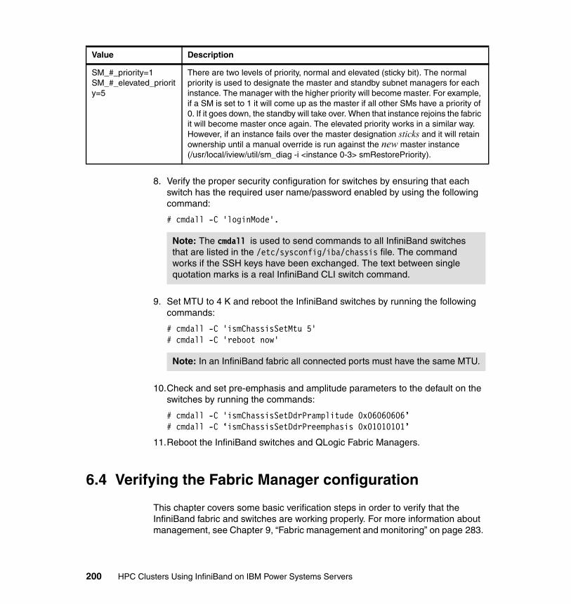
8. Verify the proper security configuration for switches by ensuring that each switch has the required user name/password enabled by using the following command:
# cmdall -C 'loginMode'.
9. Set MTU to 4 K and reboot the InfiniBand switches by running the following commands:
# cmdall -C 'ismChassisSetMtu 5' # cmdall -C 'reboot now'
10.Check and set pre-emphasis and amplitude parameters to the default on the switches by running the commands:
# cmdall -C 'ismChassisSetDdrPramplitude 0x06060606’# cmdall -C ‘ismChassisSetDdrPreemphasis 0x01010101’
11.Reboot the InfiniBand switches and QLogic Fabric Managers.
6.4 Verifying the Fabric Manager configuration
This chapter covers some basic verification steps in order to verify that the InfiniBand fabric and switches are working properly. For more information about management, see Chapter 9, “Fabric management and monitoring” on page 283.
SM_#_priority=1SM_#_elevated_priority=5
There are two levels of priority, normal and elevated (sticky bit). The normal priority is used to designate the master and standby subnet managers for each instance. The manager with the higher priority will become master. For example, if a SM is set to 1 it will come up as the master if all other SMs have a priority of 0. If it goes down, the standby will take over. When that instance rejoins the fabric it will become master once again. The elevated priority works in a similar way. However, if an instance fails over the master designation sticks and it will retain ownership until a manual override is run against the new master instance (/usr/local/iview/util/sm_diag -i <instance 0-3> smRestorePriority).
Value Description
Note: The cmdall is used to send commands to all InfiniBand switches that are listed in the /etc/sysconfig/iba/chassis file. The command works if the SSH keys have been exchanged. The text between single quotation marks is a real InfiniBand CLI switch command.
Note: In an InfiniBand fabric all connected ports must have the same MTU.
200 HPC Clusters Using InfiniBand on IBM Power Systems Servers
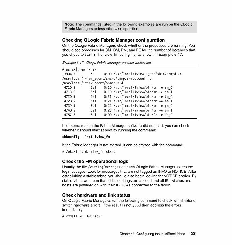
Checking QLogic Fabric Manager configurationOn the QLogic Fabric Managers check whether the processes are running. You should see processes for SM, BM, PM, and FE for the number of instances that you chose to start in the iview_fm.config file, as shown in Example 6-17.
Example 6-17 Qlogic Fabric Manager process verification
# ps ax|grep iview 3904 ? S 0:00 /usr/local/iview_agent/sbin/snmpd -c /usr/local/iview_agent/share/snmp/snmpd.conf -p /usr/local/iview_agent/snmpd.pid 4710 ? Ssl 0:10 /usr/local/iview/bin/sm -e sm_0 4713 ? Ssl 0:10 /usr/local/iview/bin/sm -e sm_1 4720 ? Ssl 0:21 /usr/local/iview/bin/bm -e bm_0 4728 ? Ssl 0:21 /usr/local/iview/bin/bm -e bm_1 4739 ? Ssl 0:22 /usr/local/iview/bin/pm -e pm_0 4748 ? Ssl 0:23 /usr/local/iview/bin/pm -e pm_1 4757 ? Ssl 0:00 /usr/local/iview/bin/fe -e fe_0
If for some reason the Fabric Manager software did not start, you can check whether it should start at boot by running the command:
chkconfig --list iview_fm
If the Fabric Manager is not started, it can be started with the command:
# /etc/init.d/iview_fm start
Check the FM operational logsUsually the file /var/log/messages on each QLogic Fabric Manager stores the log messages. Look for messages that are not tagged as INFO or NOTICE. After establishing a stable fabric, you should also begin looking for NOTICE entries. By stable fabric we mean that all the settings are applied and all IB switches and hosts are powered on with their IB HCAs connected to the fabric.
Check hardware and link status On QLogic Fabric Managers, run the following command to check for InfiniBand switch hardware errors. If the result is not good then address the errors immediately:
# cmdall -C 'hwCheck'
Note: The commands listed in the following examples are run on the QLogic Fabric Managers unless otherwise specified.
Chapter 6. Configuring the InfiniBand fabric 201
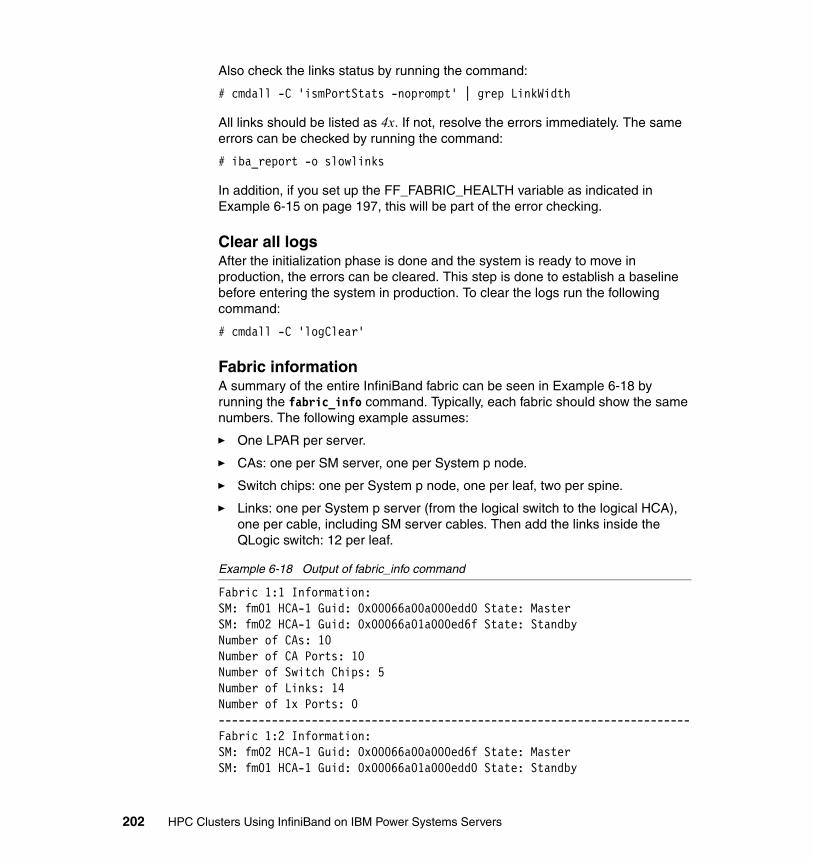
Also check the links status by running the command:
# cmdall -C 'ismPortStats -noprompt' | grep LinkWidth
All links should be listed as 4x. If not, resolve the errors immediately. The same errors can be checked by running the command:
# iba_report -o slowlinks
In addition, if you set up the FF_FABRIC_HEALTH variable as indicated in Example 6-15 on page 197, this will be part of the error checking.
Clear all logsAfter the initialization phase is done and the system is ready to move in production, the errors can be cleared. This step is done to establish a baseline before entering the system in production. To clear the logs run the following command:
# cmdall -C 'logClear'
Fabric informationA summary of the entire InfiniBand fabric can be seen in Example 6-18 by running the fabric_info command. Typically, each fabric should show the same numbers. The following example assumes:
� One LPAR per server.
� CAs: one per SM server, one per System p node.
� Switch chips: one per System p node, one per leaf, two per spine.
� Links: one per System p server (from the logical switch to the logical HCA), one per cable, including SM server cables. Then add the links inside the QLogic switch: 12 per leaf.
Example 6-18 Output of fabric_info command
Fabric 1:1 Information:SM: fm01 HCA-1 Guid: 0x00066a00a000edd0 State: MasterSM: fm02 HCA-1 Guid: 0x00066a01a000ed6f State: StandbyNumber of CAs: 10Number of CA Ports: 10Number of Switch Chips: 5Number of Links: 14Number of 1x Ports: 0-----------------------------------------------------------------------Fabric 1:2 Information:SM: fm02 HCA-1 Guid: 0x00066a00a000ed6f State: MasterSM: fm01 HCA-1 Guid: 0x00066a01a000edd0 State: Standby
202 HPC Clusters Using InfiniBand on IBM Power Systems Servers

Number of CAs: 10Number of CA Ports: 10Number of Switch Chips: 18Number of Links: 38Number of 1x Ports: 0-----------------------------------------------------------------------
Other considerationsThere are several ways to prepare an InfiniBand switch. In a HPC environment, due to the number of switches, most of the operation is done centralized from the QLogic Fabric Managers.
However, in order to understand each step we chose to use a manual approach, so each step is done individually. See Chapter 9, “Fabric management and monitoring” on page 283, for helpful hints on collecting fabric information after installation and configuration. This information will be helpful when the fabric changes and for debugging issues.
Chapter 6. Configuring the InfiniBand fabric 203

204 HPC Clusters Using InfiniBand on IBM Power Systems Servers
Chapter 7. Configuring InfiniBand on AIX
This chapter discusses the installation of a high performance cluster (HPC) using AIX 6.1 on a POWER6 architecture. Although this chapter details each step of the process, it focuses mainly on the HPC stack and InfiniBand infrastructure.
More information about specific steps or procedures is found in each product manual or guide.
7
© Copyright IBM Corp. 2009. All rights reserved. 205
7.1 Software environment
At the time of writing, based on our HPC scenarios described in Chapter 5, “Implementation overview” on page 161, we used the following products:
� Operating system: AIX 6.1 TL03� Architecture: Power PC, using latest IBM Power 6 servers� xCAT 2.2 for AIX with build: snap200904161238� GPFS Version 3.2.1.11� LAPI Version 3.1.3.1� PE Version 5.1.1.1� LoadLeveler 3.5.1.1
Preparing the platform In this chapter our main focus is to describe the necessary steps for creating a working HPC infrastructure based on InfiniBand technology. We do not cover all the aspects of the HPC cluster installation, as the listed tasks are already done.
� All the hardware is installed and operational.
� Cabling is done based on our scenarios described in Chapter 5, “Implementation overview” on page 161, following the layout and requirements for Ethernet, Fibre Channel, and InfiniBand.
� The operating system (OS) (AIX 6.1-03) for xCAT management server is already installed.
� IP address scheme is complete and IP addresses are already assigned, as listed in 5.1.1, “Network topology” on page 163.
� Our systems have sufficient storage available for OS and all other necessary packages.
� We do not cover high-availability requirements in this chapter, unless otherwise specified.
� All nodes (management, storage, and compute) are installed with basic software packages unless otherwise specified.
� Although all nodes are connected to one flat management network (one subnet) that may differ from a real-life installation, we still use the management node to connect to the compute nodes.
206 HPC Clusters Using InfiniBand on IBM Power Systems Servers
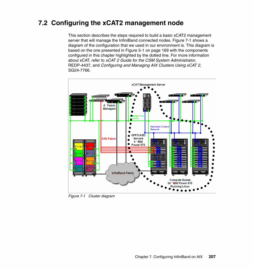
7.2 Configuring the xCAT2 management node
This section describes the steps required to build a basic xCAT2 management server that will manage the InfiniBand connected nodes. Figure 7-1 shows a diagram of the configuration that we used in our environment is. This diagram is based on the one presented in Figure 5-1 on page 169 with the components configured in this chapter highlighted by the dotted line. For more information about xCAT, refer to xCAT 2 Guide for the CSM System Administrator, REDP-4437, and Configuring and Managing AIX Clusters Using xCAT 2, SG24-7766.
Figure 7-1 Cluster diagram
Chapter 7. Configuring InfiniBand on AIX 207
7.2.1 Configuring the OS for the xCAT management node
An overview of the initial steps are below:
1. Verify that the xCAT2 server and that HMC are at the recommended levels. Refer to the IBM Clusters with the InfiniBand switch: POWER6 Recommended code levels readme at:
http://www14.software.ibm.com/webapp/set2/sas/f/networkmanager/power6/codelevels.html
2. Install the base operating system (BOS). Check whether the NIM master package is installed. It will be needed later for configuring the NIM server during the xCAT management node setup.
3. Create a file system in rootvg that will be used to store the AIX Base Operating System packages and other required software. This will be used later in creating NIM resources for the xCAT management node:
# crfs -v jfs2 -g rootvg -m /export -A yes -a size=10G# mount /export; mkdir -p /export/6100-TL3
4. Copy the BOS files from the AIX DVD into the /export/6100-TL3 directory. Make sure that you replicate the directory structure on the AIX install DVD in this directory (installp/ppc; RPMS/ppc; usr/swlag)
5. Configure the network according to your site (IP addresses, routing, and so on).
6. Add the following directories to your $PATH variable:
/opt/xcat/bin:/opt/xcat/sbin:/opt/xcat/bin:/opt/xcat/sbin:/opt/xcat/bin:/opt/xcat/sbin
7. Using additional internal disks (or appropriate SAN-based disks) create a volume group that will store the xCAT2 installation and OS repositories. We created the datavg volume group:
# mkvg -s 128 -M s -f -y datavg hdisk4 hdisk5datavg
8. Create the xCAT2 file system:
# crfs -v jfs2 -g datavg -m /install -A yes -a size=10G
9. Mirror the datavg volume group:
# mirrorvg datavg0516-1804 chvg: The quorum change takes effect immediately.
Note: We recommend mirroring the root volume group.
208 HPC Clusters Using InfiniBand on IBM Power Systems Servers
10.install the OpenSSH and OpenSSL packages required to enable SSH to the xCAT2 management server.
11.increase the size of the /opt file system, otherwise dependency package installs will fail. We did this with:
# chfs -a size=+500M /opt
12.Fix the root users ulimit with:
# /usr/bin/chuser fsize=-1 root# ulimit unlimited
13.Update RPM virtual packages:
# /usr/sbin/updtvpkg
14.Configure NTP on the management node. The management node is a Stratum 10 NTP server (undisciplined local clock):
a. Edit the NTP configuration file as shown in Example 7-1.
Example 7-1 AIX NTP configuration
# cat /etc/ntp.conf
server 127.127.1.0fudge 127.127.1.0 stratum 10driftfile /etc/ntp.drifttracefile /etc/ntp.trace
b. Start NTP with startsrc -s xntpd.
c. Uncomment NTP startup from /etc/rc.tcpip.
d. Confirm that NTP is functioning on the xCAT2 management server using the ntpq command, as shown in Example 7-2.
Example 7-2 Checking the NTP configuration
# ntpq -c clocklist localhoststatus=0000 clk_okay, last_clk_okaydevice="Undisciplined local clock", timecode=, poll=2, noreply=0,badformat=0, baddata=0, fudgetime1=0.000, stratum=10, refid=76.67.76.0,flags=0
Chapter 7. Configuring InfiniBand on AIX 209
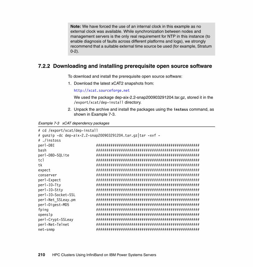
7.2.2 Downloading and installing prerequisite open source software
To download and install the prerequisite open source software:
1. Download the latest xCAT2 snapshots from:
http://xcat.sourceforge.net
We used the package dep-aix-2.2-snap200903291204.tar.gz, stored it in the /export/xcat/dep-install directory.
2. Unpack the archive and install the packages using the instoss command, as shown in Example 7-3.
Example 7-3 xCAT dependency packages
# cd /export/xcat/dep-install# gunzip -dc dep-aix-2.2-snap200903291204.tar.gz|tar -xvf -# ./instossperl-DBI ##################################################bash ##################################################perl-DBD-SQLite ##################################################tcl ##################################################tk ##################################################expect ##################################################conserver ##################################################perl-Expect ##################################################perl-IO-Tty ##################################################perl-IO-Stty ##################################################perl-IO-Socket-SSL ##################################################perl-Net_SSLeay.pm ##################################################perl-Digest-MD5 ##################################################fping ##################################################openslp ##################################################perl-Crypt-SSLeay ##################################################perl-Net-Telnet ##################################################net-snmp ##################################################
Note: We have forced the use of an internal clock in this example as no external clock was available. While synchronization between nodes and management servers is the only real requirement for NTP in this instance (to enable diagnosis of faults across different platforms and logs), we strongly recommend that a suitable external time source be used (for example, Stratum 0-2).
210 HPC Clusters Using InfiniBand on IBM Power Systems Servers
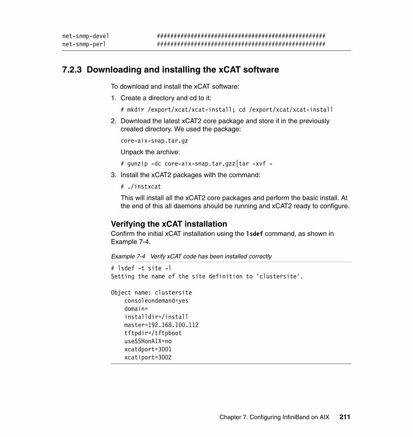
net-snmp-devel ##################################################net-snmp-perl ##################################################
7.2.3 Downloading and installing the xCAT software
To download and install the xCAT software:
1. Create a directory and cd to it:
# mkdir /export/xcat/xcat-install; cd /export/xcat/xcat-install
2. Download the latest xCAT2 core package and store it in the previously created directory. We used the package:
core-aix-snap.tar.gz
Unpack the archive:
# gunzip -dc core-aix-snap.tar.gzz|tar -xvf -
3. Install the xCAT2 packages with the command:
# ./instxcat
This will install all the xCAT2 core packages and perform the basic install. At the end of this all daemons should be running and xCAT2 ready to configure.
Verifying the xCAT installationConfirm the initial xCAT installation using the lsdef command, as shown in Example 7-4.
Example 7-4 Verify xCAT code has been installed correctly
# lsdef -t site -lSetting the name of the site definition to 'clustersite'.
Object name: clustersite consoleondemand=yes domain= installdir=/install master=192.168.100.112 tftpdir=/tftpboot useSSHonAIX=no xcatdport=3001 xcatiport=3002
Chapter 7. Configuring InfiniBand on AIX 211

7.2.4 Configuring the xCAT management node
Additional configuration of xCAT2 may be required. We have performed the following tasks:
1. Configuring xCAT2 to use SSH for AIX nodes:
# chdef -t site -o clustersite useSSHonAIX=yes
2. Configuring the root password that will be set for nodes when they are installed:
# chtab key=system passwd.username=root passwd.password=itsoadmin
3. Configuring the address of a centralized NTP server, in this case the management server:
# chtab key=ntpservers site.value=mgtibaix
4. We also added the HMCs to the xCAT2 configuration. The HMCs are configured as a special type of node:
# mkdef -t node -o hmcib01 groups="all" nodetype=hmc mgt=hmc username=hscroot password=abc123
5. Configuring xCAT2 power management of the nodes:
a. Create the stanza file:
# rscan –z hmcib01 > /install/mystanzafile
This should be completed for all HMCs that control nodes that will be InfiniBand connected. Optionally, you can edit the stanza file to only contain the nodes that you wish to install/control with xCAT2.
b. Import the stanza file into xCAT2:
# cat /install/mystanzafile |mkdef -z
c. Create appropriate node groups with your newly defined nodes (two groups, aixnodes, and frames), as shown in Example 7-5.
Example 7-5 Creating node groups
# chdef -t node -p -o nodeaix[01-24] groups=aixnodes# chdef -t node -p -o\Server-8203-E4A-SN105E094-Node2,Server-8203-E4A-SN105E0C4-Node3,\Server-8203-E4A-SN105E0B4-Node4,Server-8203-E4A-SN105E0A4-Node1,\p550-SN106629E groups=frames
212 HPC Clusters Using InfiniBand on IBM Power Systems Servers
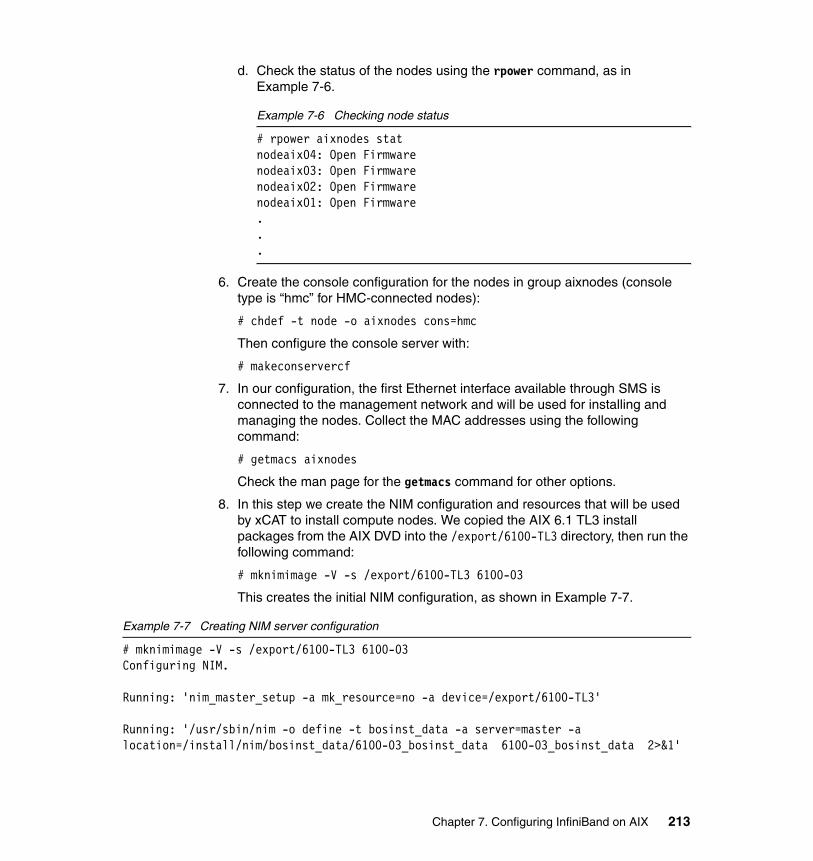
d. Check the status of the nodes using the rpower command, as in Example 7-6.
Example 7-6 Checking node status
# rpower aixnodes statnodeaix04: Open Firmwarenodeaix03: Open Firmwarenodeaix02: Open Firmwarenodeaix01: Open Firmware...
6. Create the console configuration for the nodes in group aixnodes (console type is “hmc” for HMC-connected nodes):
# chdef -t node -o aixnodes cons=hmc
Then configure the console server with:
# makeconservercf
7. In our configuration, the first Ethernet interface available through SMS is connected to the management network and will be used for installing and managing the nodes. Collect the MAC addresses using the following command:
# getmacs aixnodes
Check the man page for the getmacs command for other options.
8. In this step we create the NIM configuration and resources that will be used by xCAT to install compute nodes. We copied the AIX 6.1 TL3 install packages from the AIX DVD into the /export/6100-TL3 directory, then run the following command:
# mknimimage -V -s /export/6100-TL3 6100-03
This creates the initial NIM configuration, as shown in Example 7-7.
Example 7-7 Creating NIM server configuration
# mknimimage -V -s /export/6100-TL3 6100-03Configuring NIM.
Running: 'nim_master_setup -a mk_resource=no -a device=/export/6100-TL3'
Running: '/usr/sbin/nim -o define -t bosinst_data -a server=master -a location=/install/nim/bosinst_data/6100-03_bosinst_data 6100-03_bosinst_data 2>&1'
Chapter 7. Configuring InfiniBand on AIX 213
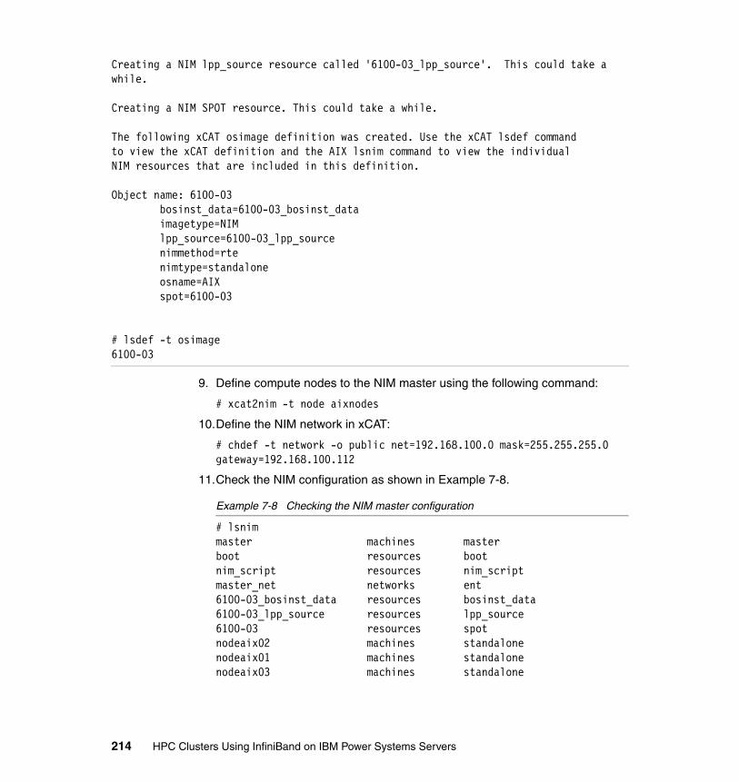
Creating a NIM lpp_source resource called '6100-03_lpp_source'. This could take a while.
Creating a NIM SPOT resource. This could take a while.
The following xCAT osimage definition was created. Use the xCAT lsdef commandto view the xCAT definition and the AIX lsnim command to view the individualNIM resources that are included in this definition.
Object name: 6100-03 bosinst_data=6100-03_bosinst_data imagetype=NIM lpp_source=6100-03_lpp_source nimmethod=rte nimtype=standalone osname=AIX spot=6100-03
# lsdef -t osimage6100-03
9. Define compute nodes to the NIM master using the following command:
# xcat2nim -t node aixnodes
10.Define the NIM network in xCAT:
# chdef -t network -o public net=192.168.100.0 mask=255.255.255.0 gateway=192.168.100.112
11.Check the NIM configuration as shown in Example 7-8.
Example 7-8 Checking the NIM master configuration
# lsnimmaster machines masterboot resources bootnim_script resources nim_scriptmaster_net networks ent6100-03_bosinst_data resources bosinst_data6100-03_lpp_source resources lpp_source6100-03 resources spotnodeaix02 machines standalonenodeaix01 machines standalonenodeaix03 machines standalone
214 HPC Clusters Using InfiniBand on IBM Power Systems Servers
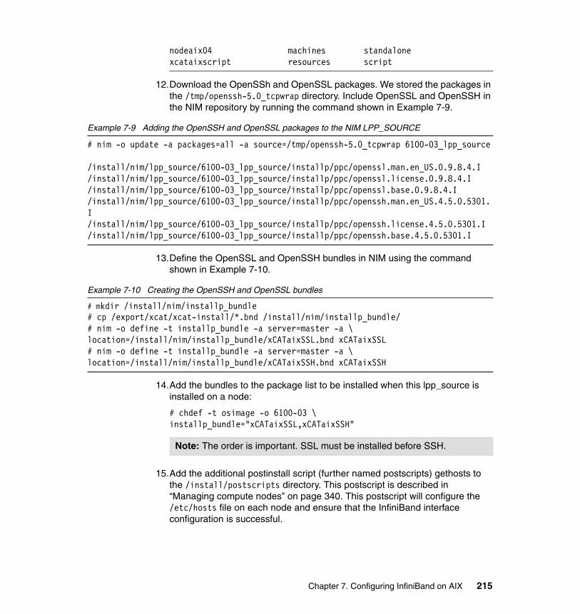
nodeaix04 machines standalonexcataixscript resources script
12.Download the OpenSSh and OpenSSL packages. We stored the packages in the /tmp/openssh-5.0_tcpwrap directory. Include OpenSSL and OpenSSH in the NIM repository by running the command shown in Example 7-9.
Example 7-9 Adding the OpenSSH and OpenSSL packages to the NIM LPP_SOURCE
# nim -o update -a packages=all -a source=/tmp/openssh-5.0_tcpwrap 6100-03_lpp_source
/install/nim/lpp_source/6100-03_lpp_source/installp/ppc/openssl.man.en_US.0.9.8.4.I/install/nim/lpp_source/6100-03_lpp_source/installp/ppc/openssl.license.0.9.8.4.I/install/nim/lpp_source/6100-03_lpp_source/installp/ppc/openssl.base.0.9.8.4.I/install/nim/lpp_source/6100-03_lpp_source/installp/ppc/openssh.man.en_US.4.5.0.5301.I/install/nim/lpp_source/6100-03_lpp_source/installp/ppc/openssh.license.4.5.0.5301.I/install/nim/lpp_source/6100-03_lpp_source/installp/ppc/openssh.base.4.5.0.5301.I
13.Define the OpenSSL and OpenSSH bundles in NIM using the command shown in Example 7-10.
Example 7-10 Creating the OpenSSH and OpenSSL bundles
# mkdir /install/nim/installp_bundle# cp /export/xcat/xcat-install/*.bnd /install/nim/installp_bundle/# nim -o define -t installp_bundle -a server=master -a \location=/install/nim/installp_bundle/xCATaixSSL.bnd xCATaixSSL# nim -o define -t installp_bundle -a server=master -a \location=/install/nim/installp_bundle/xCATaixSSH.bnd xCATaixSSH
14.Add the bundles to the package list to be installed when this lpp_source is installed on a node:
# chdef -t osimage -o 6100-03 \ installp_bundle="xCATaixSSL,xCATaixSSH"
15.Add the additional postinstall script (further named postscripts) gethosts to the /install/postscripts directory. This postscript is described in “Managing compute nodes” on page 340. This postscript will configure the /etc/hosts file on each node and ensure that the InfiniBand interface configuration is successful.
Note: The order is important. SSL must be installed before SSH.
Chapter 7. Configuring InfiniBand on AIX 215
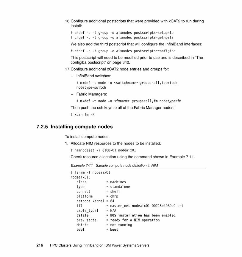
16.Configure additional postscripts that were provided with xCAT2 to run during install:
# chdef -p -t group -o aixnodes postscripts=setupntp# chdef -p -t group -o aixnodes postscripts=gethosts
We also add the third postscript that will configure the InfiniBand interfaces:
# chdef -p -t group -o aixnodes postscripts=configiba
This postscript will need to be modified prior to use and is described in “The configiba postscript” on page 340.
17.Configure additional xCAT2 node entries and groups for:
– InfiniBand switches:
# mkdef -t node -o <switchname> groups=all,ibswitch nodetype=switch
– Fabric Managers:
# mkdef -t node -o <fmname> groups=all,fm nodetype=fm
Then push the ssh keys to all of the Fabric Manager nodes:
# xdsh fm -K
7.2.5 Installing compute nodes
To install compute nodes:
1. Allocate NIM resources to the nodes to be installed:
# nimnodeset -i 6100-03 nodeaix01
Check resource allocation using the command shown in Example 7-11.
Example 7-11 Sample compute node definition in NIM
# lsnim -l nodeaix01nodeaix01: class = machines type = standalone connect = shell platform = chrp netboot_kernel = 64 if1 = master_net nodeaix01 00215e4989e0 ent cable_type1 = N/A Cstate = BOS installation has been enabled prev_state = ready for a NIM operation Mstate = not running boot = boot
216 HPC Clusters Using InfiniBand on IBM Power Systems Servers
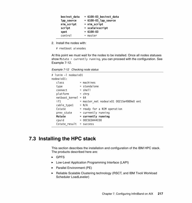
bosinst_data = 6100-03_bosinst_data lpp_source = 6100-03_lpp_source nim_script = nim_script script = xcataixscript spot = 6100-03 control = master
2. Install the nodes with:
# rnetboot aixnodes
At this point we must wait for the nodes to be installed. Once all nodes statuses show Mstate = currently running, you can proceed with the configuration. See Example 7-12.
Example 7-12 Checking node status
# lsnim -l nodeaix01nodeaix01: class = machines type = standalone connect = shell platform = chrp netboot_kernel = 64 if1 = master_net nodeaix01 00215e4989e0 ent cable_type1 = N/A Cstate = ready for a NIM operation prev_state = currently running Mstate = currently running cpuid = 00C5E0A44C00 Cstate_result = success
7.3 Installing the HPC stack
This section describes the installation and configuration of the IBM HPC stack. The products described here are:
� GPFS
� Low-Level Application Programming Interface (LAPI)
� Parallel Environment (PE)
� Reliable Scalable Clustering technology (RSCT, and IBM Tivoli Workload Scheduler LoadLeveler)
Chapter 7. Configuring InfiniBand on AIX 217
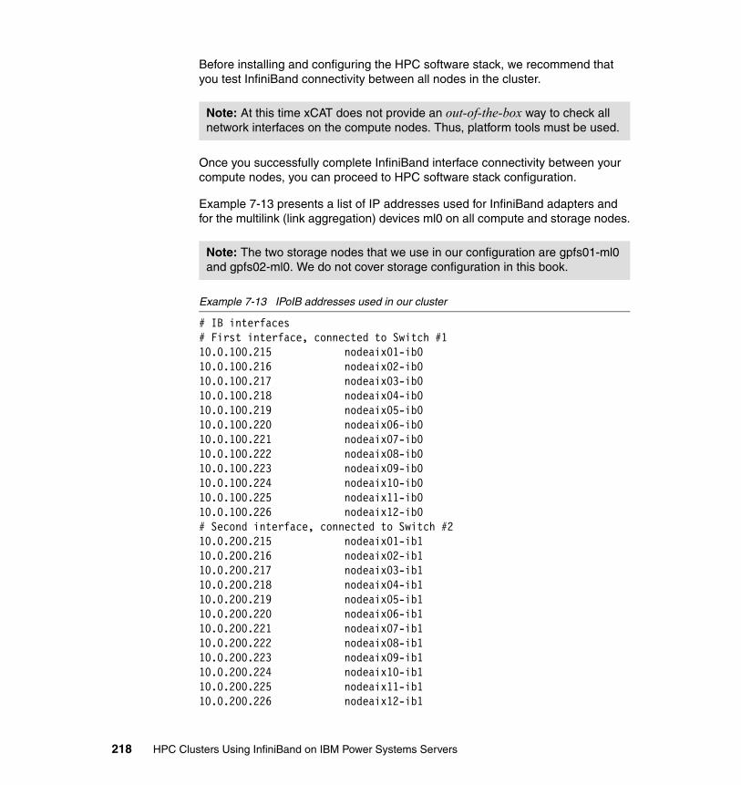
Before installing and configuring the HPC software stack, we recommend that you test InfiniBand connectivity between all nodes in the cluster.
Once you successfully complete InfiniBand interface connectivity between your compute nodes, you can proceed to HPC software stack configuration.
Example 7-13 presents a list of IP addresses used for InfiniBand adapters and for the multilink (link aggregation) devices ml0 on all compute and storage nodes.
Example 7-13 IPoIB addresses used in our cluster
# IB interfaces# First interface, connected to Switch #110.0.100.215 nodeaix01-ib010.0.100.216 nodeaix02-ib010.0.100.217 nodeaix03-ib010.0.100.218 nodeaix04-ib010.0.100.219 nodeaix05-ib010.0.100.220 nodeaix06-ib010.0.100.221 nodeaix07-ib010.0.100.222 nodeaix08-ib010.0.100.223 nodeaix09-ib010.0.100.224 nodeaix10-ib010.0.100.225 nodeaix11-ib010.0.100.226 nodeaix12-ib0# Second interface, connected to Switch #210.0.200.215 nodeaix01-ib110.0.200.216 nodeaix02-ib110.0.200.217 nodeaix03-ib110.0.200.218 nodeaix04-ib110.0.200.219 nodeaix05-ib110.0.200.220 nodeaix06-ib110.0.200.221 nodeaix07-ib110.0.200.222 nodeaix08-ib110.0.200.223 nodeaix09-ib110.0.200.224 nodeaix10-ib110.0.200.225 nodeaix11-ib110.0.200.226 nodeaix12-ib1
Note: At this time xCAT does not provide an out-of-the-box way to check all network interfaces on the compute nodes. Thus, platform tools must be used.
Note: The two storage nodes that we use in our configuration are gpfs01-ml0 and gpfs02-ml0. We do not cover storage configuration in this book.
218 HPC Clusters Using InfiniBand on IBM Power Systems Servers
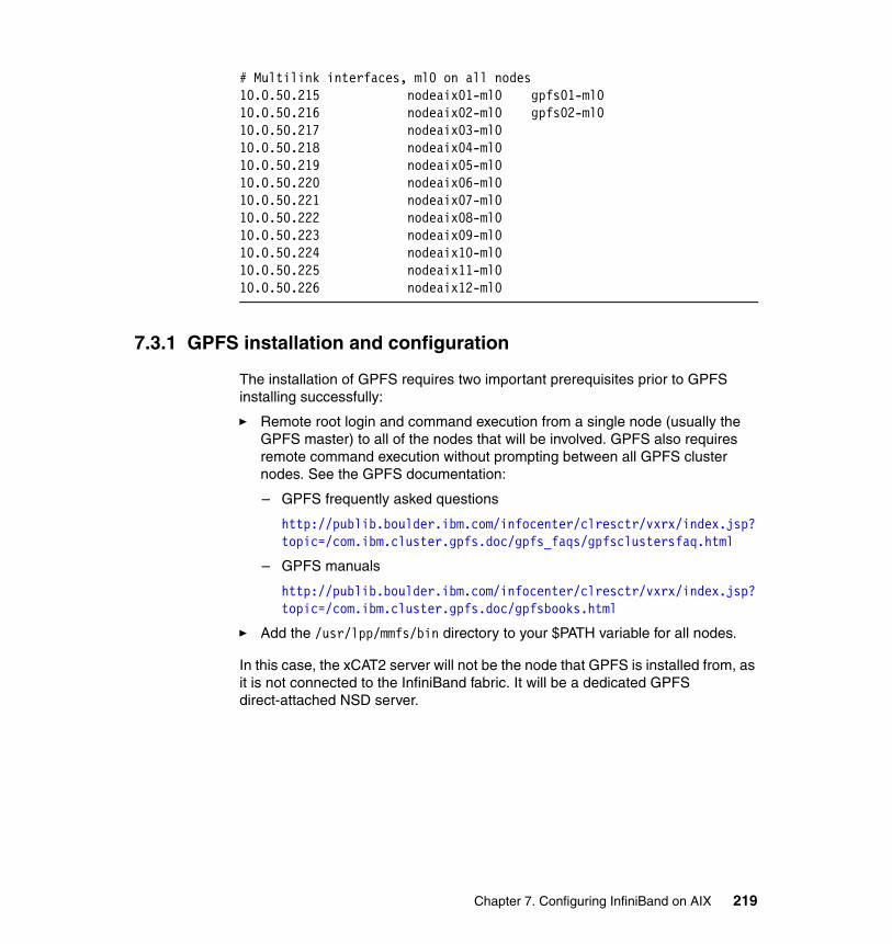
# Multilink interfaces, ml0 on all nodes10.0.50.215 nodeaix01-ml0 gpfs01-ml010.0.50.216 nodeaix02-ml0 gpfs02-ml010.0.50.217 nodeaix03-ml0 10.0.50.218 nodeaix04-ml0 10.0.50.219 nodeaix05-ml0 10.0.50.220 nodeaix06-ml0 10.0.50.221 nodeaix07-ml0 10.0.50.222 nodeaix08-ml0 10.0.50.223 nodeaix09-ml0 10.0.50.224 nodeaix10-ml0 10.0.50.225 nodeaix11-ml0 10.0.50.226 nodeaix12-ml0
7.3.1 GPFS installation and configuration
The installation of GPFS requires two important prerequisites prior to GPFS installing successfully:
� Remote root login and command execution from a single node (usually the GPFS master) to all of the nodes that will be involved. GPFS also requires remote command execution without prompting between all GPFS cluster nodes. See the GPFS documentation:
– GPFS frequently asked questions
http://publib.boulder.ibm.com/infocenter/clresctr/vxrx/index.jsp?topic=/com.ibm.cluster.gpfs.doc/gpfs_faqs/gpfsclustersfaq.html
– GPFS manuals
http://publib.boulder.ibm.com/infocenter/clresctr/vxrx/index.jsp?topic=/com.ibm.cluster.gpfs.doc/gpfsbooks.html
� Add the /usr/lpp/mmfs/bin directory to your $PATH variable for all nodes.
In this case, the xCAT2 server will not be the node that GPFS is installed from, as it is not connected to the InfiniBand fabric. It will be a dedicated GPFS direct-attached NSD server.
Chapter 7. Configuring InfiniBand on AIX 219
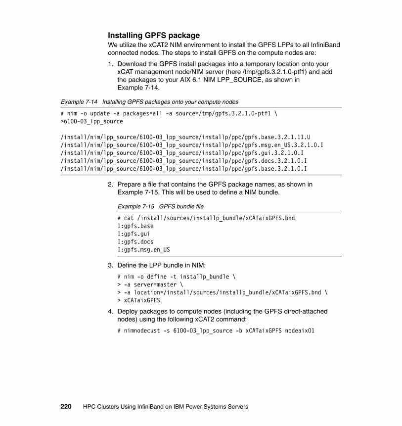
Installing GPFS packageWe utilize the xCAT2 NIM environment to install the GPFS LPPs to all InfiniBand connected nodes. The steps to install GPFS on the compute nodes are:
1. Download the GPFS install packages into a temporary location onto your xCAT management node/NIM server (here /tmp/gpfs.3.2.1.0-ptf1) and add the packages to your AIX 6.1 NIM LPP_SOURCE, as shown in Example 7-14.
Example 7-14 Installing GPFS packages onto your compute nodes
# nim -o update -a packages=all -a source=/tmp/gpfs.3.2.1.0-ptf1 \ >6100-03_lpp_source
/install/nim/lpp_source/6100-03_lpp_source/installp/ppc/gpfs.base.3.2.1.11.U/install/nim/lpp_source/6100-03_lpp_source/installp/ppc/gpfs.msg.en_US.3.2.1.0.I/install/nim/lpp_source/6100-03_lpp_source/installp/ppc/gpfs.gui.3.2.1.0.I/install/nim/lpp_source/6100-03_lpp_source/installp/ppc/gpfs.docs.3.2.1.0.I/install/nim/lpp_source/6100-03_lpp_source/installp/ppc/gpfs.base.3.2.1.0.I
2. Prepare a file that contains the GPFS package names, as shown in Example 7-15. This will be used to define a NIM bundle.
Example 7-15 GPFS bundle file
# cat /install/sources/installp_bundle/xCATaixGPFS.bndI:gpfs.baseI:gpfs.guiI:gpfs.docsI:gpfs.msg.en_US
3. Define the LPP bundle in NIM:
# nim -o define -t installp_bundle \> -a server=master \> -a location=/install/sources/installp_bundle/xCATaixGPFS.bnd \> xCATaixGPFS
4. Deploy packages to compute nodes (including the GPFS direct-attached nodes) using the following xCAT2 command:
# nimnodecust -s 6100-03_lpp_source -b xCATaixGPFS nodeaix01
220 HPC Clusters Using InfiniBand on IBM Power Systems Servers
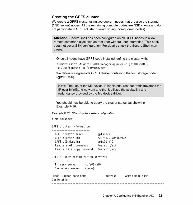
Creating the GPFS clusterWe create a GPFS cluster using two quorum nodes that are also the storage (NSD server) nodes. All the remaining compute nodes are NSD clients and do not participate in GPFS cluster quorum voting (non-quorum nodes).
1. Once all nodes have GPFS code installed, define the cluster with:
# mmcrcluster -N gpfs01-ml0:manager-quorum -p gpfs01-ml0 \-r /usr/bin/ssh -R /usr/bin/scp
We define a single-node GPFS cluster containing the first storage node (gpfs01-ml0).
You should now be able to query the cluster status, as shown in Example 7-16.
Example 7-16 Checking the cluster configuration
# mmlscluster
GPFS cluster information======================== GPFS cluster name: gpfs01-ml0 GPFS cluster id: 720741791784163972 GPFS UID domain: gpfs01-ml0 Remote shell command: /usr/bin/ssh Remote file copy command: /usr/bin/scp
GPFS cluster configuration servers:----------------------------------- Primary server: gpfs01-ml0 Secondary server: (none)
Node Daemon node name IP address Admin node name Designation-----------------------------------------------------------------------
Attention: Secure shell has been configured on all GPFS nodes to allow remote command execution as root user without user interaction. This book does not cover SSH configuration. For details check the Secure Shell man pages.
Note: The use of the ML device IP labels ensures that traffic traverses the IP over InfiniBand network and that it utilizes the scalability and redundancy provided by the ML device driver.
Chapter 7. Configuring InfiniBand on AIX 221

1 gpfs01-ml0 10.0.50.215 gpfs01-ml0 quorum-manager
2. Start the cluster and confirm that everything is operational (Example 7-17).
Example 7-17 Start the GPFS daemon
# mmstartup -aTue May 19 12:13:28 EDT 2009: mmstartup: Starting GPFS ...
# mmgetstate -a
Node number Node name GPFS state------------------------------------------ 1 gpfs01-ml0 active
3. Add the secondary quorum and storage node to the cluster using the command shown in Example 7-18.
Example 7-18 Adding the second storage/quorum node to the GPFS cluster
# mmaddnode -N gpfs02-ml0:quorum-masterTue May 19 13:42:38 EDT 2009: mmaddnode: Processing node gpfs02-ml0mmaddnode: Command successfully completedmmaddnode: Propagating the cluster configuration data to all affected nodes. This is an asynchronous process.
4. Set the newly added node to be a secondary configuration data server, as shown in Example 7-19.
Example 7-19 Configuring secondary cluster data server
# mmchcluster -s gpfs02-ml0mmchcluster: GPFS cluster configuration servers:mmchcluster: Primary server: gpfs01-ml0mmchcluster: Secondary server: gpfs02-ml0mmchcluster: Command successfully completed
5. For each of the additional nodes (nodeaix03-12 in this case), add them as non-quorum GPFS clients:
# mmaddnode -N nodeaix<#>-ml0:nonquorum-client
222 HPC Clusters Using InfiniBand on IBM Power Systems Servers

6. Start GPFS on each node with:
# mmstartup -N nodeaix<#>-ml0
7. Once finished adding the nodes, check that all nodes have joined the cluster using the following command:
# mmgetstate -a -L
Creating network shared disks (NSDs)To configure disks on the direct-attached nodes a template file containing disk descriptors must be created and provided to GPFS. The process is:
1. Confirm the disks that are to be used on direct-attached nodes and ensure that they are visible from all storage nodes. These will be providing disk I/O.
2. Create the NSD definition file shown in Example 7-20.
Example 7-20 Disk definition file
# cat /export/diskdesc.txt#DiskName:PrimaryServer:BackupServer:DiskUsage:FailureGroup:DesiredName:StorgePoolhdisk1:gpfs01-ml0,gpfs02-ml0::dataAndMetadata::nsd1:
3. Make a backup of it, as the next step will modify the original file:
cp /export/diskdesc.txt /export/diskdesc.txt-orig
4. Configure NSDs using the previously defined file, as shown in Example 7-21.
Example 7-21 Creating the NSDs
# mmcrnsd -F /export/diskdesc.txtmmcrnsd: Processing disk hdisk1mmcrnsd: Propagating the cluster configuration data to all affected nodes. This is an asynchronous process.
5. Confirm that the disks are configured, as shown in Example 7-22.
Example 7-22 Listing NSDs
# mmlsnsd -M
Disk name NSD volume ID Device Node name Remarks-------------------------------------------------------------------- nsd1 C0A864D74A12F2A2 /dev/hdisk1 gpfs01-ml0 nsd1 C0A864D74A12F2A2 /dev/hdisk1 gpfs02-ml0
Chapter 7. Configuring InfiniBand on AIX 223
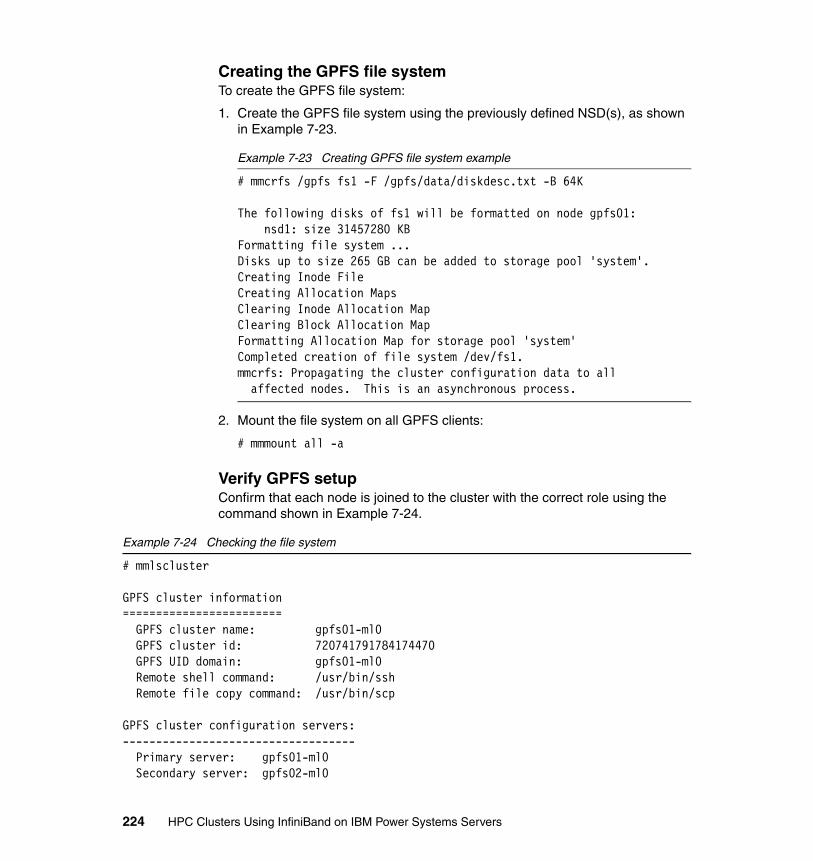
Creating the GPFS file systemTo create the GPFS file system:
1. Create the GPFS file system using the previously defined NSD(s), as shown in Example 7-23.
Example 7-23 Creating GPFS file system example
# mmcrfs /gpfs fs1 -F /gpfs/data/diskdesc.txt -B 64K
The following disks of fs1 will be formatted on node gpfs01: nsd1: size 31457280 KBFormatting file system ...Disks up to size 265 GB can be added to storage pool 'system'.Creating Inode FileCreating Allocation MapsClearing Inode Allocation MapClearing Block Allocation MapFormatting Allocation Map for storage pool 'system'Completed creation of file system /dev/fs1.mmcrfs: Propagating the cluster configuration data to all affected nodes. This is an asynchronous process.
2. Mount the file system on all GPFS clients:
# mmmount all -a
Verify GPFS setupConfirm that each node is joined to the cluster with the correct role using the command shown in Example 7-24.
Example 7-24 Checking the file system
# mmlscluster
GPFS cluster information======================== GPFS cluster name: gpfs01-ml0 GPFS cluster id: 720741791784174470 GPFS UID domain: gpfs01-ml0 Remote shell command: /usr/bin/ssh Remote file copy command: /usr/bin/scp
GPFS cluster configuration servers:----------------------------------- Primary server: gpfs01-ml0 Secondary server: gpfs02-ml0
224 HPC Clusters Using InfiniBand on IBM Power Systems Servers
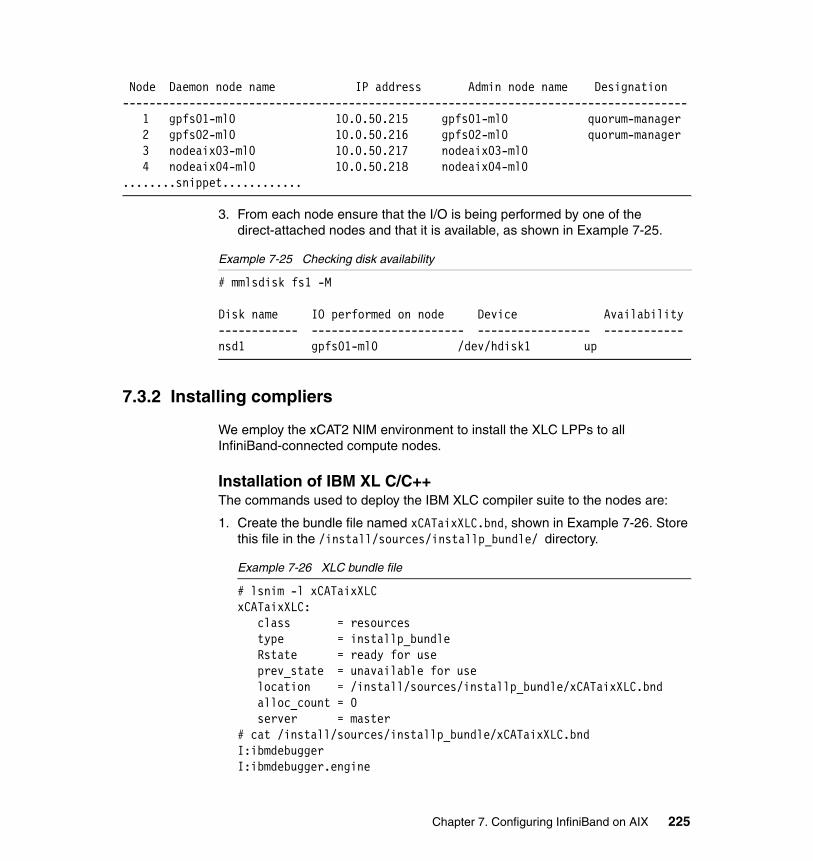
Node Daemon node name IP address Admin node name Designation------------------------------------------------------------------------------------- 1 gpfs01-ml0 10.0.50.215 gpfs01-ml0 quorum-manager 2 gpfs02-ml0 10.0.50.216 gpfs02-ml0 quorum-manager 3 nodeaix03-ml0 10.0.50.217 nodeaix03-ml0 4 nodeaix04-ml0 10.0.50.218 nodeaix04-ml0........snippet............
3. From each node ensure that the I/O is being performed by one of the direct-attached nodes and that it is available, as shown in Example 7-25.
Example 7-25 Checking disk availability
# mmlsdisk fs1 -M
Disk name IO performed on node Device Availability------------ ----------------------- ----------------- ------------nsd1 gpfs01-ml0 /dev/hdisk1 up
7.3.2 Installing compliers
We employ the xCAT2 NIM environment to install the XLC LPPs to all InfiniBand-connected compute nodes.
Installation of IBM XL C/C++The commands used to deploy the IBM XLC compiler suite to the nodes are:
1. Create the bundle file named xCATaixXLC.bnd, shown in Example 7-26. Store this file in the /install/sources/installp_bundle/ directory.
Example 7-26 XLC bundle file
# lsnim -l xCATaixXLCxCATaixXLC: class = resources type = installp_bundle Rstate = ready for use prev_state = unavailable for use location = /install/sources/installp_bundle/xCATaixXLC.bnd alloc_count = 0 server = master# cat /install/sources/installp_bundle/xCATaixXLC.bndI:ibmdebuggerI:ibmdebugger.engine
Chapter 7. Configuring InfiniBand on AIX 225

I:ibmdebugger.engine.msg.en_USI:ibmdebugger.jreI:ibmdebugger.uiI:memdbg.adtI:memdbg.aix53I:memdbg.msg.en_USI:vac.BndI:vac.CI:vac.aix53I:vac.html.commonI:vac.html.en_USI:vac.includeI:vac.libI:vac.licI:vac.licAgreementI:vac.man.en_USI:vac.msg.en_USI:vac.ndiI:vac.pdf.en_US.CI:vacpp.BndI:vacpp.cmpI:vacpp.cmp.aix53I:vacpp.cmp.aix53.libI:vacpp.cmp.coreI:vacpp.cmp.includeI:vacpp.html.commonI:vacpp.html.en_USI:vacpp.licI:vacpp.licAgreementI:vacpp.man.en_USI:vacpp.memdbgI:vacpp.memdbg.aix53I:vacpp.msg.en_USI:vacpp.ndiI:vacpp.pdf.en_USI:vacpp.samplesI:xlC.adtI:xlC.aix50I:xlC.aix61I:xlC.rteI:xlf.BndI:xlf.licI:xlf.licAgreementI:xlf.man.en_USI:xlf.ndi
226 HPC Clusters Using InfiniBand on IBM Power Systems Servers

I:xlfcmpI:xlfcmp.aix53I:xlfcmp.html.commonI:xlfcmp.html.en_USI:xlfcmp.msg.en_USI:xlfcmp.pdf.en_USI:xlfrteI:xlfrte.aix53I:xlfrte.msg.en_USI:xlhelp.comI:xlhelp.html.en_USI:xlmass.adt.includeI:xlmass.aix53.libI:xlmass.libI:xlsmp.aix53.rteI:xlsmp.msg.en_US.rteI:xlsmp.rte
2. We have copied the XLC packages into a temporary (staging) directory and added the LPP files into the AIX 6.1 TL3 lpp_source:
# nim -o update -a packages=all \> -a source=/tmp/xlf12_vac10 6100-03_lpp_source
3. We defined the bundle into the NIM configuration:
# nim -o define -t installp_bundle -a server=master \> -a location=/install/sources/installp_bundle/xCATaixXLC.bnd \ > xCATaixXLC
4. Finally, we deployed the bundle using xCAT2:
# nimnodecust -s 6100-03_lpp_source -b xCATaixXLC aixnodes
7.3.3 PE installation and testing
We employ the xCAT2 NIM environment to install the PE LPPs to all InfiniBand-connected compute nodes.
Chapter 7. Configuring InfiniBand on AIX 227
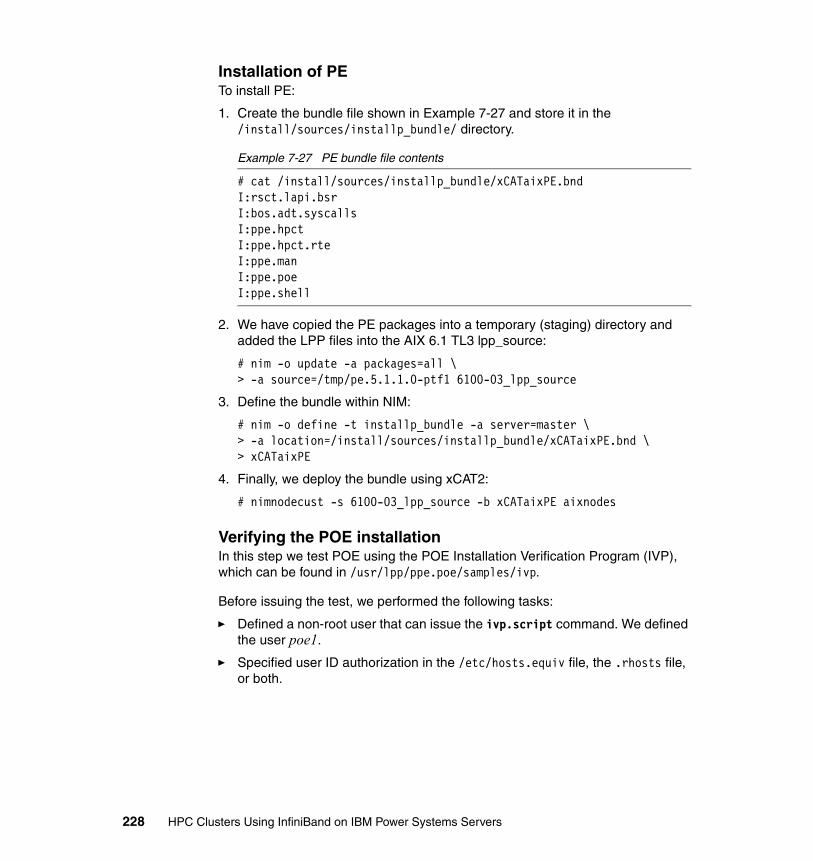
Installation of PETo install PE:
1. Create the bundle file shown in Example 7-27 and store it in the /install/sources/installp_bundle/ directory.
Example 7-27 PE bundle file contents
# cat /install/sources/installp_bundle/xCATaixPE.bndI:rsct.lapi.bsrI:bos.adt.syscallsI:ppe.hpctI:ppe.hpct.rteI:ppe.manI:ppe.poeI:ppe.shell
2. We have copied the PE packages into a temporary (staging) directory and added the LPP files into the AIX 6.1 TL3 lpp_source:
# nim -o update -a packages=all \> -a source=/tmp/pe.5.1.1.0-ptf1 6100-03_lpp_source
3. Define the bundle within NIM:
# nim -o define -t installp_bundle -a server=master \> -a location=/install/sources/installp_bundle/xCATaixPE.bnd \ > xCATaixPE
4. Finally, we deploy the bundle using xCAT2:
# nimnodecust -s 6100-03_lpp_source -b xCATaixPE aixnodes
Verifying the POE installation In this step we test POE using the POE Installation Verification Program (IVP), which can be found in /usr/lpp/ppe.poe/samples/ivp.
Before issuing the test, we performed the following tasks:
� Defined a non-root user that can issue the ivp.script command. We defined the user poe1.
� Specified user ID authorization in the /etc/hosts.equiv file, the .rhosts file, or both.
228 HPC Clusters Using InfiniBand on IBM Power Systems Servers

� Defined the path to the C compiler in the user ID’s profile.
� Example 7-28 shows an example of the expected output after issuing the two commands shown on each cluster node.
Example 7-28 Verifying POE installation
# su - poe1$ export LANG=C$ /usr/lpp/ppe.poe/samples/ivp/ivp.scriptVerifying the existence of the BinariesPartition Manager daemon /etc/pmdv5 is executablePOE files seem to be in orderCompiling the ivp sample programOutput files will be stored in directory /tmp/ivp479382Creating host.list file for this nodeSetting the required environment variablesExecuting the parallel program with 2 tasks
POE IVP: running as task 0 on node nodeaix04POE IVP: there are 2 tasks runningPOE IVP: all messages sentPOE IVP: running as task 1 on node nodeaix04POE IVP: task 1 received <POE IVP Message Passing Text>
Parallel program ivp.out return code was 0
Executing the parallel program with 2 tasks, threaded library
POE IVP_r: running as task 0 on node nodeaix04POE IVP_r: there are 2 tasks runningPOE IVP_r: all messages sentPOE IVP_r: running as task 1 on node nodeaix04POE IVP_r: task 1 received <POE IVP Message Passing Text - Threaded Library>
Parallel program ivp_r.out return code was 0
If both tests return a return code of 0, POE IVP is successful. To test message passing, run the tests in /usr/lpp/ppe.poe/samples/poetest.bw and poetest.cast To test threaded message passing, run the tests in /usr/lpp/ppe.poe/samples/threadsEnd of IVP test$ exit
Chapter 7. Configuring InfiniBand on AIX 229
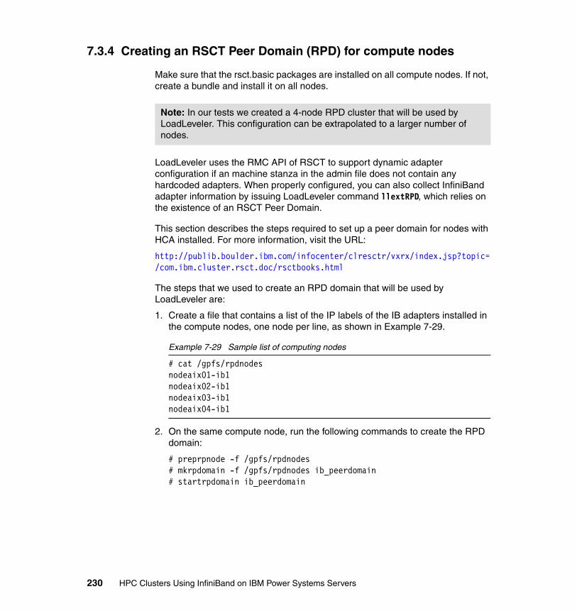
7.3.4 Creating an RSCT Peer Domain (RPD) for compute nodes
Make sure that the rsct.basic packages are installed on all compute nodes. If not, create a bundle and install it on all nodes.
LoadLeveler uses the RMC API of RSCT to support dynamic adapter configuration if an machine stanza in the admin file does not contain any hardcoded adapters. When properly configured, you can also collect InfiniBand adapter information by issuing LoadLeveler command llextRPD, which relies on the existence of an RSCT Peer Domain.
This section describes the steps required to set up a peer domain for nodes with HCA installed. For more information, visit the URL:
http://publib.boulder.ibm.com/infocenter/clresctr/vxrx/index.jsp?topic=/com.ibm.cluster.rsct.doc/rsctbooks.html
The steps that we used to create an RPD domain that will be used by LoadLeveler are:
1. Create a file that contains a list of the IP labels of the IB adapters installed in the compute nodes, one node per line, as shown in Example 7-29.
Example 7-29 Sample list of computing nodes
# cat /gpfs/rpdnodesnodeaix01-ib1nodeaix02-ib1nodeaix03-ib1nodeaix04-ib1
2. On the same compute node, run the following commands to create the RPD domain:
# preprpnode -f /gpfs/rpdnodes# mkrpdomain -f /gpfs/rpdnodes ib_peerdomain# startrpdomain ib_peerdomain
Note: In our tests we created a 4-node RPD cluster that will be used by LoadLeveler. This configuration can be extrapolated to a larger number of nodes.
230 HPC Clusters Using InfiniBand on IBM Power Systems Servers
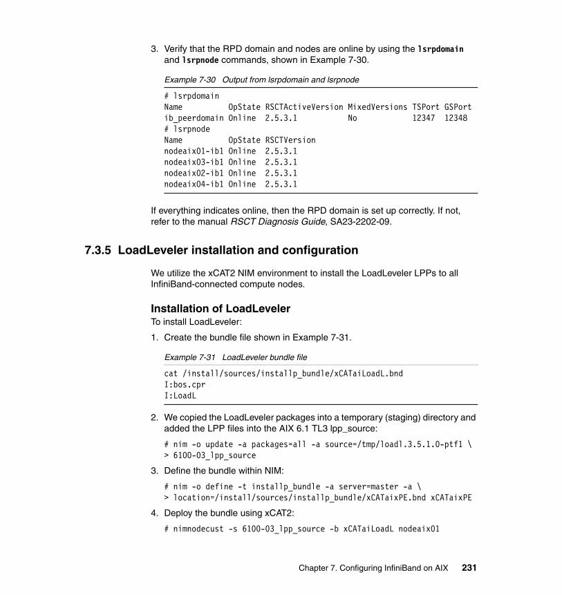
3. Verify that the RPD domain and nodes are online by using the lsrpdomain and lsrpnode commands, shown in Example 7-30.
Example 7-30 Output from lsrpdomain and lsrpnode
# lsrpdomainName OpState RSCTActiveVersion MixedVersions TSPort GSPortib_peerdomain Online 2.5.3.1 No 12347 12348# lsrpnodeName OpState RSCTVersionnodeaix01-ib1 Online 2.5.3.1nodeaix03-ib1 Online 2.5.3.1nodeaix02-ib1 Online 2.5.3.1nodeaix04-ib1 Online 2.5.3.1
If everything indicates online, then the RPD domain is set up correctly. If not, refer to the manual RSCT Diagnosis Guide, SA23-2202-09.
7.3.5 LoadLeveler installation and configuration
We utilize the xCAT2 NIM environment to install the LoadLeveler LPPs to all InfiniBand-connected compute nodes.
Installation of LoadLevelerTo install LoadLeveler:
1. Create the bundle file shown in Example 7-31.
Example 7-31 LoadLeveler bundle file
cat /install/sources/installp_bundle/xCATaiLoadL.bndI:bos.cprI:LoadL
2. We copied the LoadLeveler packages into a temporary (staging) directory and added the LPP files into the AIX 6.1 TL3 lpp_source:
# nim -o update -a packages=all -a source=/tmp/loadl.3.5.1.0-ptf1 \ > 6100-03_lpp_source
3. Define the bundle within NIM:
# nim -o define -t installp_bundle -a server=master -a \ > location=/install/sources/installp_bundle/xCATaixPE.bnd xCATaixPE
4. Deploy the bundle using xCAT2:
# nimnodecust -s 6100-03_lpp_source -b xCATaiLoadL nodeaix01
Chapter 7. Configuring InfiniBand on AIX 231
7.4 Start the application
At this time start your applications to verify the environment or use sample applications distributed with the code. These are explained below. For complete information refer to the readme file supplied with each application.
7.4.1 MPI thread sample application
The purpose of this sample program is to use MPI message passing library with user-created threads. It is located in /usr/lpp/ppe.poe/samples/threads and contains the following files:
� README.threads� Makefile� threaded_ring.c� threads.run
Build and run the executable:
1. Log onto the system as a non-root user and do the following:
a. Put these files in a location that is readable and writable by all hosts. Then go to this directory.
b. Compile the source program that compiles threaded_ring.c and creates the threads executable:
make -f makefile
2. Create a host file called host.list. Put one host per line with a minimum of two nodes.
3. Make sure that the nodes specified in the host.list file are initialized for the requested type of message passing.
Note: To simplify the installation or re-installation of additional or existing nodes, we add the bundles that were created in previous sections to the default bundle list that is installed with the lpp_source by running the following commands on the xCAT management node/NIM master:
# chdef -t osimage -o 6100-03 \# installp_bundle="xCATaixSSL,xCATaixSSH, \ > xCATaixGPFS,xCATaixXLC,xCATaixLAPI,xCATaixPE,xCATaiLoadL"
232 HPC Clusters Using InfiniBand on IBM Power Systems Servers

4. Run the program. It has two inputs, ip and us. The ip option uses the UDP/IP library. The us option uses the user space library and is the default.
threads.run [{ip,us}]
5. If successful the program should return the following from task 0:
TEST COMPLETE
7.4.2 Bandwidth sample application
The purpose of this sample program is to perform a point-to-point bandwidth measurement test. It is located in /usr/lpp/ppe.poe/samples/poetest.bw and contains the following files:
� README.bw� bw.f� bw.run� makefile
Build and run the executable:
1. Log onto the system and as a non-root user do the following:
a. Put these files in a location that is readable and writable by all hosts. Then go to this directory.
b. Compile the source program that compiles bw.f and creates the bw executable:
make -f makefile
2. Create a host file called host.list with two entries. Put one host per line.
3. Run the program. It has two inputs, ip or us. The ip option is for IP message passing. The us option is for user-space message passing and is the default.
bw.run [{ip,us}]
4. If successful the program should return the following:
Hello from node 0Hello from node 1MEASURED BANDWIDTH = ....... *10**6 Bytes/sec
7.4.3 Broadcast sample application
The purpose of this sample program is to perform a broadcast from task 0 node to the rest of the nodes in the cluster. This way, the test code touches all nodes in
Note: A FORTRAN compiler is required.
Chapter 7. Configuring InfiniBand on AIX 233

the cluster. It is located in /usr/lpp/ppe.poe/samples/poetest.cast and contains the following four files.
� README.cast� bcast.f� bcast.run � makefile
Build and run the executable:
1. Log onto the system and as a non-root user do the following:
a. Put the these files in a location that is readable and writable by all hosts. Then go to this directory.
b. Compile the source program that compiles bcast.f and creates the bcast executable:
make -f makefile
2. Create a host file called host.list. Put one host per line.
3. Make sure that the nodes specified in the host.list file are initialized for the requested type of message passing.
4. Run the program. It has two inputs, ntasks, and ip or us. ntasks is the number of tasks (nodes) in the cluster. Make sure that there are at least ntasks entries in the host.list file. The ip option is for IP message passing. The us option is for user-space message passing and is the default.
bcast.run [ntasks [{ip,us}]
5. If successful the program should return the following:
Hello from node 0Hello from node 1...Hello from node (p-1)BROADCAST TEST COMPLETED SUCCESSFULLY
If the test failed, you should see on the terminal:
BROADCAST TEST FAILED on node x (where x is some integer)
Note: The FORTRAN compiler must be available.
234 HPC Clusters Using InfiniBand on IBM Power Systems Servers

Chapter 8. Configuring InfiniBand on Linux on Power
This chapter describes the installation of a high performance computing cluster on IBM POWER6 Systems with InfiniBand running SUSE Linux Enterprise Server version 11. The topics covered are:
� Configuring the xCAT management node – Configuring the OS for the xCAT management node– Setting up logging in xCAT using syslog-ng
� Installing the HPC stack– Configuring the InfiniBand drivers– Installing the HPC software using xCAT– Installing LAPI– Configuring the HPC software
� Starting the application
8
Note: This chapter describes the procedure for using xCAT management functionality available at the time of the writing. For the latest information refer to the product Web pages listed at the end of this chapter.
© Copyright IBM Corp. 2009. All rights reserved. 235
8.1 Software environment
At the time of writing, based on our HPC scenarios described in Chapter 5, “Implementation overview” on page 161, we used the following products:
� Operating system: SUSE Enterprise Linux Server Version 11� Architecture: Power PC, using latest IBM POWER6 servers� xCAT 2.2 with build: snap200904161238� GPFS Version 3.2.1.12� LAPI Version 3.1.3.1� PE Version 5.1.1.1� LoadLeveler 3.5.1.1
Preparing the platform In this section we describe the steps that we used to create a working HPC infrastructure using InfiniBand interconnect. We do not cover all aspects of the HPC cluster installation. We focus on the cluster management aspects. We assume that:
� All the hardware is installed and operational.
� Cabling is done based on our scenarios described in Chapter 5, “Implementation overview” on page 161, following the layout and requirements for Ethernet, Fibre Channel, and InfiniBand.
� The OS (SLES 11 PPC) for the xCAT management server is already installed.
� The IP addresses scheme is complete and IP addresses are already assigned, as described in 5.1.1, “Network topology” on page 163.
� Our systems have sufficient storage available for OS and all other necessary packages.
� We do not cover high-availability requirements in this chapter, unless otherwise specified.
� All nodes (management, storage, and compute) are installed with basic software packages unless otherwise specified.
� Although all nodes are connected to one flat management network (one subnet) that may differ from a real-life installation, we still use the management node to connect to the compute nodes.
236 HPC Clusters Using InfiniBand on IBM Power Systems Servers
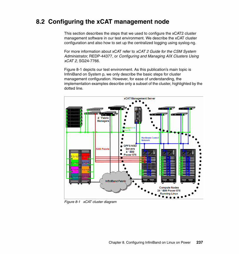
8.2 Configuring the xCAT management node
This section describes the steps that we used to configure the xCAT2 cluster management software in our test environment. We describe the xCAT cluster configuration and also how to set up the centralized logging using syslog-ng.
For more information about xCAT refer to xCAT 2 Guide for the CSM System Administrator, REDP-44377, or Configuring and Managing AIX Clusters Using xCAT 2, SG24-7766.
Figure 8-1 depicts our test environment. As this publication’s main topic is InfiniBand on System p, we only describe the basic steps for cluster management configuration. However, for ease of understanding, the implementation examples describe only a subset of the cluster, highlighted by the dotted line.
Figure 8-1 xCAT cluster diagram
Chapter 8. Configuring InfiniBand on Linux on Power 237

8.2.1 Configuring the OS for the xCAT management node
In this section we describe the xCAT installation on an existing server running SUSE Enterprise Linux Server. The following preparation steps are required for the node that will be used as the xCAT management node (MN).
1. Disable the firewall.
For the ease of the installation we disable the firewall as shown in Example 8-1. However, if disabling the firewall completely is not an option, configure iptables to allow the following services to and from the management network (192.168.100/24 subnet in our case):
– DHCP– TFTP– NFS– HTTP– FTP– DNS
Also, we disable the apparmor in our environment.
Example 8-1 Disabling the firewall on SLES 11
mgtIBlnx:/ #chkconfig SuSEfirewall2_setup offmgtIBlnx:/ #chkconfig SuSEfirewall2_init off
2. Empty the name server configuration:
# > /etc/resolv.conf
In an HPC environment using a DNS server may create performance problems, as any new connection between cluster nodes must be resolved into IP by the DNS server, resulting in a bottleneck. For our installation we choose to use local network name resolution only, in the /etc/hosts file.
3. Set up the NTP.
In general, in cluster environments, time synchronization between systems is crucial. Moreover, in an HPC cluster that runs a parallel application, this is even more important, as application barriers may slow down execution due to unsynchronized node time. We do recommend that you synchronize your
Note: The following steps are based on the xCAT documentation, which can be accessed at:
https://xcat.svn.sourceforge.net/svnroot/xcat/xcat-core/trunk/xCAT-client/share/doc/
238 HPC Clusters Using InfiniBand on IBM Power Systems Servers
xCAT management node to a Stratum 0 or Stratum 1 server, and synchronize your cluster elements to the xCAT management server (which in turn becomes a Stratum 1 or 2).
However, for simplicity, in our environment we set up our xCAT management node as a standalone NTP server (Stratum 10, synchronized to its internal hardware clock), as shown in Example 8-2. For details about NTP see:
http://www.ntp.org
Example 8-2 xCAT management node ntp.conf
mgtIBlnx:/ # cat /etc/ntp.conf......snippet........server 127.127.1.0 # local clock (LCL)fudge 127.127.1.0 stratum 10 # LCL is unsynchronizeddriftfile /var/lib/ntp/drift/ntp.drift # path for drift filelogfile /var/log/ntp # alternate log file......snippet......
8.2.2 Installing prerequisite Open Source Software and xCAT code
To install:
1. Access the xCAT download page at:
http://xcat.sourceforge.net/yum/download.html
Download the following packages:
core-rpms-snap.tar.bz2 (for the latest daily build) xcat-dep*.tar.bz2
2. Copy the *.tar.bz packages to the xCAT management node in a directory of your choice and untar them by running "tar zxvf <file_name>" for each file, as shown in Example 8-3.
Example 8-3 Preparing the xCAT repository
mgtIBlnx:/kits/xcat/2.2.1/plinux # ls -ltotal 57588-rw------- 1 root root 6963200 Jul 8 13:33 core-rpms-snap.tar.bz2-rw------- 1 root root 51937280 Jul 8 14:04 xcat-dep-2.2.1-200905140948.tar.bz2mgtIBlnx:/kits/xcat/2.2.1/plinux # bzip2 -d core-rpms-snap.tar.bz2
Note: The dependencies can be accessed by following the link "xCAT SourceForge xcat-dep download page," and at the bottom of the page you will find the xcat-dep structure.
Chapter 8. Configuring InfiniBand on Linux on Power 239
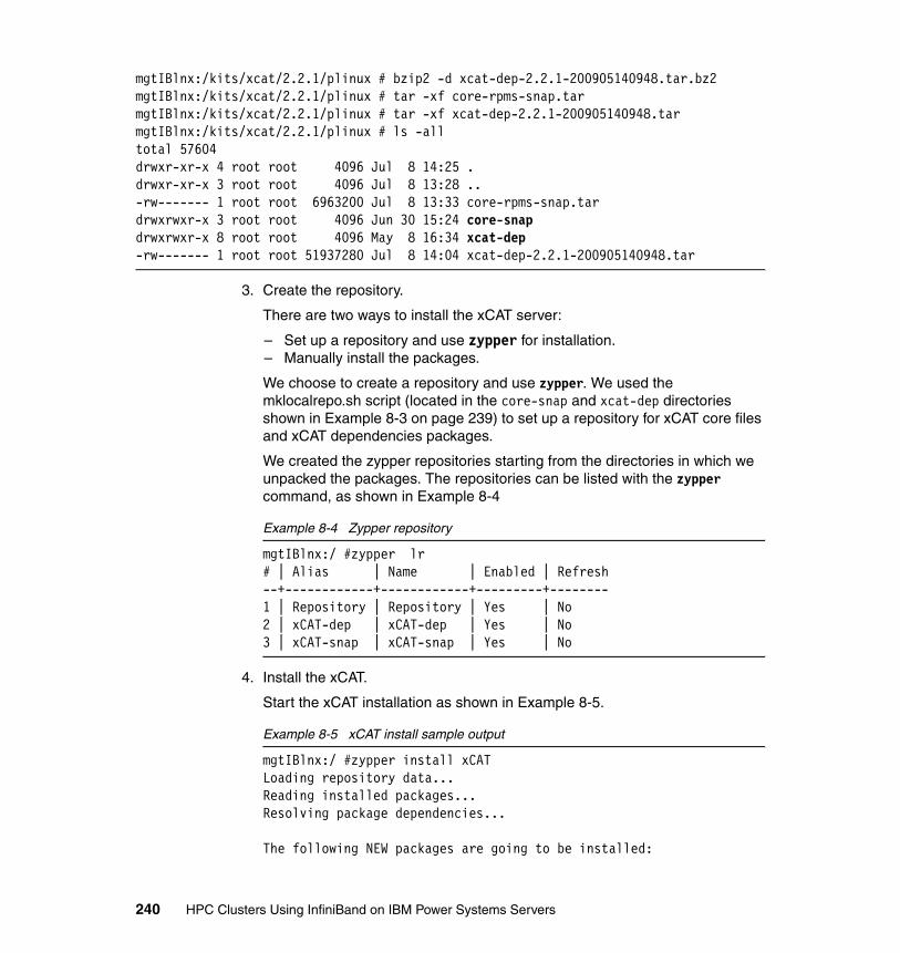
mgtIBlnx:/kits/xcat/2.2.1/plinux # bzip2 -d xcat-dep-2.2.1-200905140948.tar.bz2mgtIBlnx:/kits/xcat/2.2.1/plinux # tar -xf core-rpms-snap.tarmgtIBlnx:/kits/xcat/2.2.1/plinux # tar -xf xcat-dep-2.2.1-200905140948.tarmgtIBlnx:/kits/xcat/2.2.1/plinux # ls -alltotal 57604drwxr-xr-x 4 root root 4096 Jul 8 14:25 .drwxr-xr-x 3 root root 4096 Jul 8 13:28 ..-rw------- 1 root root 6963200 Jul 8 13:33 core-rpms-snap.tardrwxrwxr-x 3 root root 4096 Jun 30 15:24 core-snapdrwxrwxr-x 8 root root 4096 May 8 16:34 xcat-dep-rw------- 1 root root 51937280 Jul 8 14:04 xcat-dep-2.2.1-200905140948.tar
3. Create the repository.
There are two ways to install the xCAT server:
– Set up a repository and use zypper for installation.– Manually install the packages.
We choose to create a repository and use zypper. We used the mklocalrepo.sh script (located in the core-snap and xcat-dep directories shown in Example 8-3 on page 239) to set up a repository for xCAT core files and xCAT dependencies packages.
We created the zypper repositories starting from the directories in which we unpacked the packages. The repositories can be listed with the zypper command, as shown in Example 8-4
Example 8-4 Zypper repository
mgtIBlnx:/ #zypper lr# | Alias | Name | Enabled | Refresh--+------------+------------+---------+--------1 | Repository | Repository | Yes | No2 | xCAT-dep | xCAT-dep | Yes | No3 | xCAT-snap | xCAT-snap | Yes | No
4. Install the xCAT.
Start the xCAT installation as shown in Example 8-5.
Example 8-5 xCAT install sample output
mgtIBlnx:/ #zypper install xCATLoading repository data...Reading installed packages...Resolving package dependencies...
The following NEW packages are going to be installed:
240 HPC Clusters Using InfiniBand on IBM Power Systems Servers
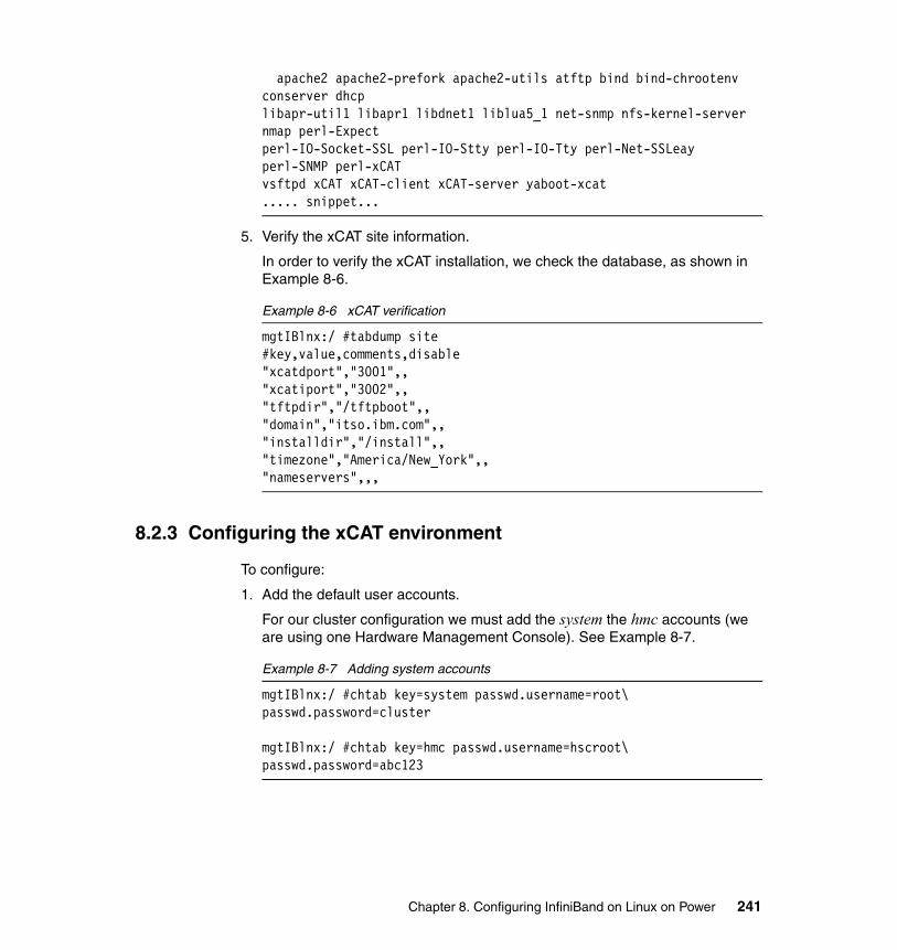
apache2 apache2-prefork apache2-utils atftp bind bind-chrootenv conserver dhcplibapr-util1 libapr1 libdnet1 liblua5_1 net-snmp nfs-kernel-server nmap perl-Expectperl-IO-Socket-SSL perl-IO-Stty perl-IO-Tty perl-Net-SSLeay perl-SNMP perl-xCATvsftpd xCAT xCAT-client xCAT-server yaboot-xcat..... snippet...
5. Verify the xCAT site information.
In order to verify the xCAT installation, we check the database, as shown in Example 8-6.
Example 8-6 xCAT verification
mgtIBlnx:/ #tabdump site#key,value,comments,disable"xcatdport","3001",,"xcatiport","3002",,"tftpdir","/tftpboot",,"domain","itso.ibm.com",,"installdir","/install",,"timezone","America/New_York",,"nameservers",,,
8.2.3 Configuring the xCAT environment
To configure:
1. Add the default user accounts.
For our cluster configuration we must add the system the hmc accounts (we are using one Hardware Management Console). See Example 8-7.
Example 8-7 Adding system accounts
mgtIBlnx:/ #chtab key=system passwd.username=root\ passwd.password=cluster
mgtIBlnx:/ #chtab key=hmc passwd.username=hscroot\ passwd.password=abc123
Chapter 8. Configuring InfiniBand on Linux on Power 241

2. Define HMC as an xCAT node.
The HMC must be defined as a regular node, even though it is not used as a compute node. The HMC definition is shown in Example 8-8.
Example 8-8 HMC node definition
mgtIBlnx:/ #mkdef -t node -o hmcIB01 groups=hmc,all nodetype=hmc mgtIBlnx:/ #mgt=hmc username=hscroot password=abc123
3. Add the compute nodes.
Scan the HMC using the rscan command, as shown in Example 8-9, and store the command output in a file. Modify the file (in our case the node.def file) if you must take out some node definitions. To add the nodes to the xCAT database, run the chdef command as described in the same example. To list the nodes use the lsdef command.
Example 8-9 Add the compute nodes
mgtIBlnx:/ #rscan -z hmcIB01 > node.defmgtIBlnx:/ #cat node.def |chdef -zmgtIBlnx:/ #lsdef -t node -l all
4. Add the node attributes.
We must define all the required information that the xCAT needs in order to install the node over the network. See Example 8-10.
Example 8-10 Add the remote install attributes (this is one line)
mgtIBlnx:/ #chdef -t node -o nodelnx01-nodelnx04 netboot=yaboot\ tftpserver=192.168.100.111 nfsserver=192.168.100.11\ monserver=192.168.100.111 xcatmaster=192.168.100.111\ installnic="eth0" primarynic="eth0" os=sles11 arch=ppc64\ profile=compute
Note: The node definition file also must contain the frame information. It is listed as a separate node entry, as in Example 8-18 on page 246. Note that the lpar definition has as parent the frame definition.
242 HPC Clusters Using InfiniBand on IBM Power Systems Servers
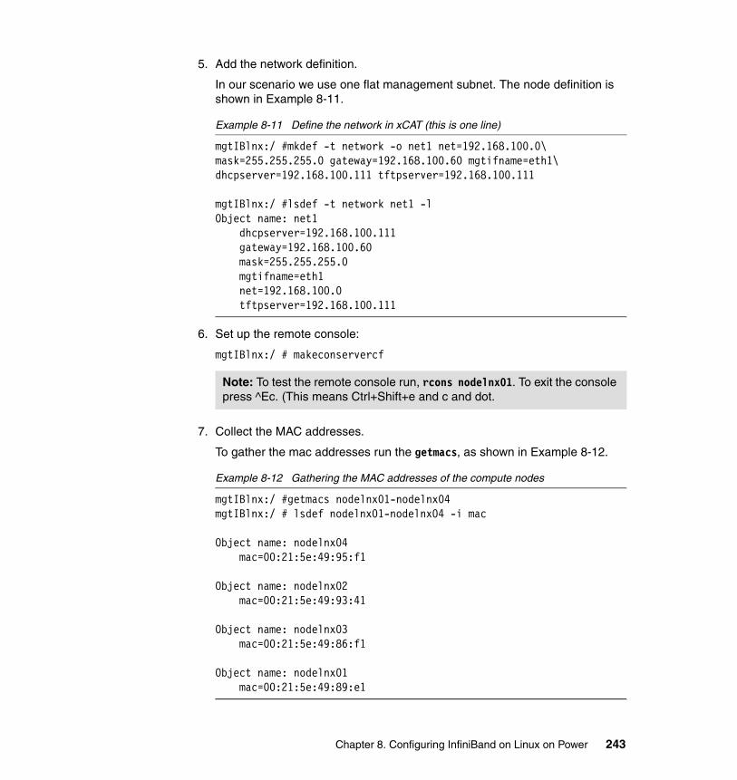
5. Add the network definition.
In our scenario we use one flat management subnet. The node definition is shown in Example 8-11.
Example 8-11 Define the network in xCAT (this is one line)
mgtIBlnx:/ #mkdef -t network -o net1 net=192.168.100.0\ mask=255.255.255.0 gateway=192.168.100.60 mgtifname=eth1\ dhcpserver=192.168.100.111 tftpserver=192.168.100.111
mgtIBlnx:/ #lsdef -t network net1 -lObject name: net1 dhcpserver=192.168.100.111 gateway=192.168.100.60 mask=255.255.255.0 mgtifname=eth1 net=192.168.100.0 tftpserver=192.168.100.111
6. Set up the remote console:
mgtIBlnx:/ # makeconservercf
7. Collect the MAC addresses.
To gather the mac addresses run the getmacs, as shown in Example 8-12.
Example 8-12 Gathering the MAC addresses of the compute nodes
mgtIBlnx:/ #getmacs nodelnx01-nodelnx04mgtIBlnx:/ # lsdef nodelnx01-nodelnx04 -i mac
Object name: nodelnx04 mac=00:21:5e:49:95:f1
Object name: nodelnx02 mac=00:21:5e:49:93:41
Object name: nodelnx03 mac=00:21:5e:49:86:f1
Object name: nodelnx01 mac=00:21:5e:49:89:e1
Note: To test the remote console run, rcons nodelnx01. To exit the console press ^Ec. (This means Ctrl+Shift+e and c and dot.
Chapter 8. Configuring InfiniBand on Linux on Power 243
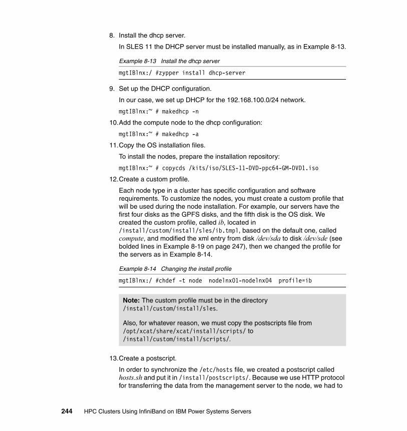
8. Install the dhcp server.
In SLES 11 the DHCP server must be installed manually, as in Example 8-13.
Example 8-13 Install the dhcp server
mgtIBlnx:/ #zypper install dhcp-server
9. Set up the DHCP configuration.
In our case, we set up DHCP for the 192.168.100.0/24 network.
mgtIBlnx:~ # makedhcp -n
10.Add the compute node to the dhcp configuration:
mgtIBlnx:~ # makedhcp -a
11.Copy the OS installation files.
To install the nodes, prepare the installation repository:
mgtIBlnx:~ # copycds /kits/iso/SLES-11-DVD-ppc64-GM-DVD1.iso
12.Create a custom profile.
Each node type in a cluster has specific configuration and software requirements. To customize the nodes, you must create a custom profile that will be used during the node installation. For example, our servers have the first four disks as the GPFS disks, and the fifth disk is the OS disk. We created the custom profile, called ib, located in /install/custom/install/sles/ib.tmpl, based on the default one, called compute, and modified the xml entry from disk /dev/sda to disk /dev/sde (see bolded lines in Example 8-19 on page 247), then we changed the profile for the servers as in Example 8-14.
Example 8-14 Changing the install profile
mgtIBlnx:/ #chdef -t node nodelnx01-nodelnx04 profile=ib
13.Create a postscript.
In order to synchronize the /etc/hosts file, we created a postscript called hosts.sh and put it in /install/postscripts/. Because we use HTTP protocol for transferring the data from the management server to the node, we had to
Note: The custom profile must be in the directory /install/custom/install/sles.
Also, for whatever reason, we must copy the postscripts file from /opt/xcat/share/xcat/install/scripts/ to /install/custom/install/scripts/.
244 HPC Clusters Using InfiniBand on IBM Power Systems Servers
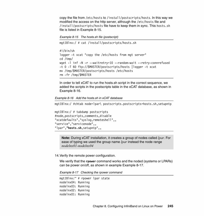
copy the file from /etc/hosts to /install/postscripts/hosts. In this way we modified the access on the http server, although the /etc/hosts file and /install/postscripts/hosts file have to keep them in sync. This hosts.sh file is listed in Example 8-15.
Example 8-15 The hosts.sh file (postscript)
mgtIBlnx:/ # cat /install/postscripts/hosts.sh
#!/bin/shlogger -t xcat "copy the /etc/hosts from mgt server"cd /tmp/wget -l inf -N -r --waitretry=10 --random-wait --retry-connrefused -t 0 -T 60 ftp://$MASTER/postscripts/hosts |logger -t xcatmv /tmp/$MASTER/postscripts/hosts /etc/hostsrm -fr /tmp/$MASTER
In order to tell xCAT to run the hosts.sh script in the correct sequence, we added the scripts in the postscripts table in the xCAT database, as shown in Example 8-16.
Example 8-16 Add the hosts.sh in xCAT database
mgtIBlnx:/ #chtab node=lpar\ postscripts.postscripts=hosts.sh,setupntp
mgtIBlnx:/ # tabdump postscripts#node,postscripts,comments,disable"xcatdefaults","syslog,remoteshell",,"service","servicenode",,"lpar","hosts.sh,setupntp",,
14.Verify the remote power configuration.
We verify that the rpower command works and the noded (systems or LPARs) can be power on/off, as shown in example Example 8-17.
Example 8-17 Checking the rpower command
mgtIBlnx:~ # rpower lpar statenodelnx04: Runningnodelnx03: Runningnodelnx02: Runningnodelnx01: Running
Note: During xCAT installation, it creates a group of nodes called lpar. For ease of typing we used the group name lpar instead the node range nodelnx01-nodelnx04
Chapter 8. Configuring InfiniBand on Linux on Power 245
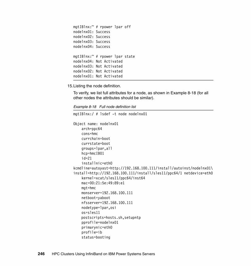
mgtIBlnx:~ # rpower lpar offnodelnx01: Successnodelnx02: Successnodelnx03: Successnodelnx04: Success
mgtIBlnx:~ # rpower lpar statenodelnx04: Not Activatednodelnx03: Not Activatednodelnx02: Not Activatednodelnx01: Not Activated
15.Listing the node definition.
To verify, we list full attributes for a node, as shown in Example 8-18 (for all other nodes the attributes should be similar).
Example 8-18 Full node definition list
mgtIBlnx:/ # lsdef -t node nodelnx01
Object name: nodelnx01 arch=ppc64 cons=hmc currchain=boot currstate=boot groups=lpar,all hcp=hmcIB01 id=21 installnic=eth0kcmdline=autoyast=http://192.168.100.111/install/autoinst/nodelnx01\ install=http://192.168.100.111/install/sles11/ppc64/1 netdevice=eth0 kernel=xcat/sles11/ppc64/inst64 mac=00:21:5e:49:89:e1 mgt=hmc monserver=192.168.100.111 netboot=yaboot nfsserver=192.168.100.111 nodetype=lpar,osi os=sles11
postscripts=hosts.sh,setupntp pprofile=nodelnx01 primarynic=eth0 profile=ib status=booting
246 HPC Clusters Using InfiniBand on IBM Power Systems Servers
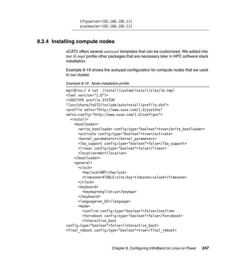
tftpserver=192.168.100.111 xcatmaster=192.168.100.111
8.2.4 Installing compute nodes
xCAT2 offers several autoyast templates that can be customized. We added into our ib.tmpl profile other packages that are necessary later in HPC software stack installation.
Example 8-19 shows the autoyast configuration for compute nodes that we used in our cluster.
Example 8-19 Node installation profile
mgtIBlnx:/ # cat /install/custom/install/sles/ib.tmpl<?xml version="1.0"?><!DOCTYPE profile SYSTEM "/usr/share/YaST2/include/autoinstall/profile.dtd"><profile xmlns="http://www.suse.com/1.0/yast2ns" xmlns:config="http://www.suse.com/1.0/configns"> <install> <bootloader> <write_bootloader config:type="boolean">true</write_bootloader> <activate config:type="boolean">true</activate> <kernel_parameters></kernel_parameters> <lba_support config:type="boolean">false</lba_support> <linear config:type="boolean">false</linear> <location>mbr</location> </bootloader> <general> <clock> <hwclock>GMT</hwclock> <timezone>#TABLE:site:key=timezone:value#</timezone> </clock> <keyboard> <keymap>english-us</keymap> </keyboard> <language>en_US</language> <mode> <confirm config:type="boolean">false</confirm> <forceboot config:type="boolean">false</forceboot> <interactive_boot config:type="boolean">false</interactive_boot><final_reboot config:type="boolean">true</final_reboot>
Chapter 8. Configuring InfiniBand on Linux on Power 247
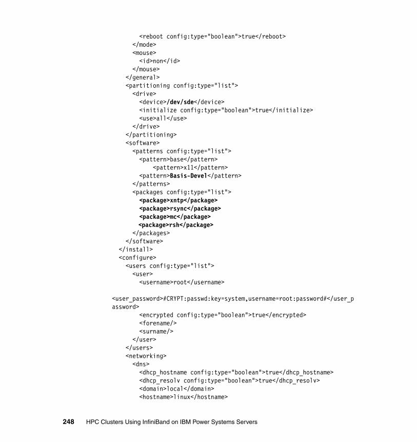
<reboot config:type="boolean">true</reboot> </mode> <mouse> <id>non</id> </mouse> </general> <partitioning config:type="list"> <drive> <device>/dev/sde</device> <initialize config:type="boolean">true</initialize> <use>all</use> </drive> </partitioning> <software> <patterns config:type="list"> <pattern>base</pattern> <pattern>x11</pattern> <pattern>Basis-Devel</pattern> </patterns> <packages config:type="list"> <package>xntp</package> <package>rsync</package> <package>mc</package>
<package>rsh</package> </packages> </software> </install> <configure> <users config:type="list"> <user> <username>root</username> <user_password>#CRYPT:passwd:key=system,username=root:password#</user_password> <encrypted config:type="boolean">true</encrypted> <forename/> <surname/> </user> </users> <networking> <dns> <dhcp_hostname config:type="boolean">true</dhcp_hostname> <dhcp_resolv config:type="boolean">true</dhcp_resolv> <domain>local</domain> <hostname>linux</hostname>
248 HPC Clusters Using InfiniBand on IBM Power Systems Servers
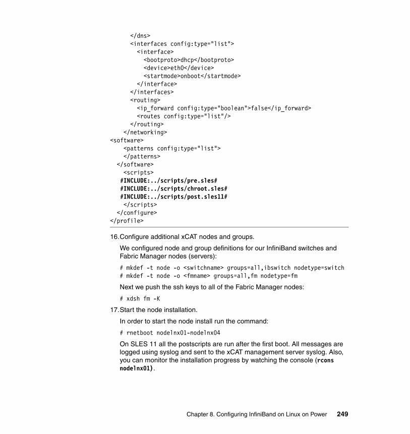
</dns> <interfaces config:type="list"> <interface> <bootproto>dhcp</bootproto> <device>eth0</device> <startmode>onboot</startmode> </interface> </interfaces> <routing> <ip_forward config:type="boolean">false</ip_forward> <routes config:type="list"/> </routing> </networking><software> <patterns config:type="list"> </patterns> </software> <scripts> #INCLUDE:../scripts/pre.sles# #INCLUDE:../scripts/chroot.sles# #INCLUDE:../scripts/post.sles11# </scripts> </configure></profile>
16.Configure additional xCAT nodes and groups.
We configured node and group definitions for our InfiniBand switches and Fabric Manager nodes (servers):
# mkdef -t node -o <switchname> groups=all,ibswitch nodetype=switch# mkdef -t node -o <fmname> groups=all,fm nodetype=fm
Next we push the ssh keys to all of the Fabric Manager nodes:
# xdsh fm -K
17.Start the node installation.
In order to start the node install run the command:
# rnetboot nodelnx01-nodelnx04
On SLES 11 all the postscripts are run after the first boot. All messages are logged using syslog and sent to the xCAT management server syslog. Also, you can monitor the installation progress by watching the console (rcons nodelnx01).
Chapter 8. Configuring InfiniBand on Linux on Power 249
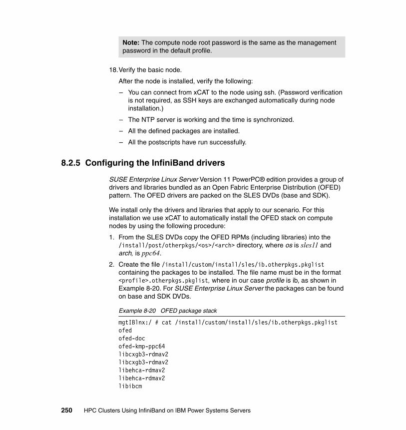
18.Verify the basic node.
After the node is installed, verify the following:
– You can connect from xCAT to the node using ssh. (Password verification is not required, as SSH keys are exchanged automatically during node installation.)
– The NTP server is working and the time is synchronized.
– All the defined packages are installed.
– All the postscripts have run successfully.
8.2.5 Configuring the InfiniBand drivers
SUSE Enterprise Linux Server Version 11 PowerPC® edition provides a group of drivers and libraries bundled as an Open Fabric Enterprise Distribution (OFED) pattern. The OFED drivers are packed on the SLES DVDs (base and SDK).
We install only the drivers and libraries that apply to our scenario. For this installation we use xCAT to automatically install the OFED stack on compute nodes by using the following procedure:
1. From the SLES DVDs copy the OFED RPMs (including libraries) into the /install/post/otherpkgs/<os>/<arch> directory, where os is sles11 and arch, is ppc64.
2. Create the file /install/custom/install/sles/ib.otherpkgs.pkglist containing the packages to be installed. The file name must be in the format <profile>.otherpkgs.pkglist, where in our case profile is ib, as shown in Example 8-20. For SUSE Enterprise Linux Server the packages can be found on base and SDK DVDs.
Example 8-20 OFED package stack
mgtIBlnx:/ # cat /install/custom/install/sles/ib.otherpkgs.pkglistofedofed-docofed-kmp-ppc64libcxgb3-rdmav2libcxgb3-rdmav2libehca-rdmav2libehca-rdmav2libibcm
Note: The compute node root password is the same as the management password in the default profile.
250 HPC Clusters Using InfiniBand on IBM Power Systems Servers
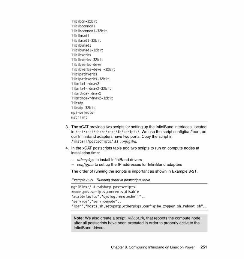
libibcm-32bitlibibcommon1libibcommon1-32bitlibibmad1libibmad1-32bitlibibumad1libibumad1-32bitlibibverbslibibverbs-32bitlibibverbs-devellibibverbs-devel-32bitlibipathverbslibipathverbs-32bitlibmlx4-rdmav2libmlx4-rdmav2-32bitlibmthca-rdmav2libmthca-rdmav2-32bitlibsdplibsdp-32bitmpi-selectormstflint
3. The xCAT provides two scripts for setting up the InfiniBand interfaces, located in /opt/xcat/share/xcat/ib/scripts/. We use the script configiba.2port, as our InfiniBand adapters have two ports. Copy the script in /install/postscripts/ as configiba.
4. In the xCAT postscripts table add two scripts to run on compute nodes at installation time:
– otherpkgs to install InfiniBand drivers – configiba to set up the IP addresses for InfiniBand adapters
The order of running the scripts is important as shown in Example 8-21.
Example 8-21 Running order in postscripts table
mgtIBlnx:/ # tabdump postscripts#node,postscripts,comments,disable"xcatdefaults","syslog,remoteshell",,"service","servicenode",,"lpar","hosts.sh,setupntp,otherpkgs,configiba,zypper.sh,reboot.sh”,,
Note: We also create a script, reboot.sh, that reboots the compute node after all postscripts have been executed in order to properly activate the InfiniBand drivers.
Chapter 8. Configuring InfiniBand on Linux on Power 251

5. Reinstall the nodes and verify that you can ping the nodes between them on all InfiniBand ports. For more information about managing the InfiniBand communication, see Chapter 9, “Fabric management and monitoring” on page 283.
In addition, we also defined another postscript, zypper.sh, which adds the SUSE Enterprise Linux Server SDK packages as a separate repository in order to solve the dependencies. The zyyper.sh script is shown in Example 8-22.
Example 8-22 zypper.sh script
#/bin/shecho "Adding SUSE-Linux-Enterprise-Software-Development-Kit-11_11-0 repository" |logger -t zypper.sh/usr/bin/zypper ar -f -t yast http://192.168.100.111/install/sles11/ppc64/sdk/ SUSE-Linux-Enterprise-Software-Development-Kit-11_11-0 |logger -t zypper.sh
8.2.6 Setting up logging in xCAT using syslog-ng
By default all the logs are dumped in a single file (/var/log/messages) on each node. Syslog offers a client server infrastructure that helps collecting log information from multiple machines into a centralized repository.
What is syslog-ngIn a cluster with a large number of nodes, dumping all logging information into a centralized repository is highly recommended. However, the amount of information collected from a cluster with a large number of nodes may be huge, making log management difficult. For this reason, new Linux installation recommends using the syslog-ng, the next-generation log management system.
Classic syslog versus syslog-ng Syslog-ng means syslog next generation. Syslog-ng has more features than the classic syslog. However, syslog is well established in the industry and almost every device (nodes, routers, switches, and so on) have implemented the syslog protocol.
252 HPC Clusters Using InfiniBand on IBM Power Systems Servers
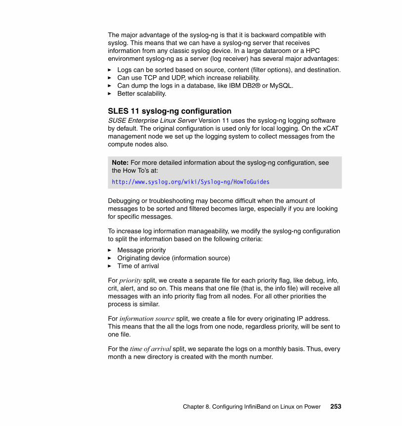
The major advantage of the syslog-ng is that it is backward compatible with syslog. This means that we can have a syslog-ng server that receives information from any classic syslog device. In a large dataroom or a HPC environment syslog-ng as a server (log receiver) has several major advantages:
� Logs can be sorted based on source, content (filter options), and destination.� Can use TCP and UDP, which increase reliability.� Can dump the logs in a database, like IBM DB2® or MySQL.� Better scalability.
SLES 11 syslog-ng configurationSUSE Enterprise Linux Server Version 11 uses the syslog-ng logging software by default. The original configuration is used only for local logging. On the xCAT management node we set up the logging system to collect messages from the compute nodes also.
Debugging or troubleshooting may become difficult when the amount of messages to be sorted and filtered becomes large, especially if you are looking for specific messages.
To increase log information manageability, we modify the syslog-ng configuration to split the information based on the following criteria:
� Message priority� Originating device (information source)� Time of arrival
For priority split, we create a separate file for each priority flag, like debug, info, crit, alert, and so on. This means that one file (that is, the info file) will receive all messages with an info priority flag from all nodes. For all other priorities the process is similar.
For information source split, we create a file for every originating IP address. This means that the all the logs from one node, regardless priority, will be sent to one file.
For the time of arrival split, we separate the logs on a monthly basis. Thus, every month a new directory is created with the month number.
Note: For more detailed information about the syslog-ng configuration, see the How To’s at:
http://www.syslog.org/wiki/Syslog-ng/HowToGuides
Chapter 8. Configuring InfiniBand on Linux on Power 253
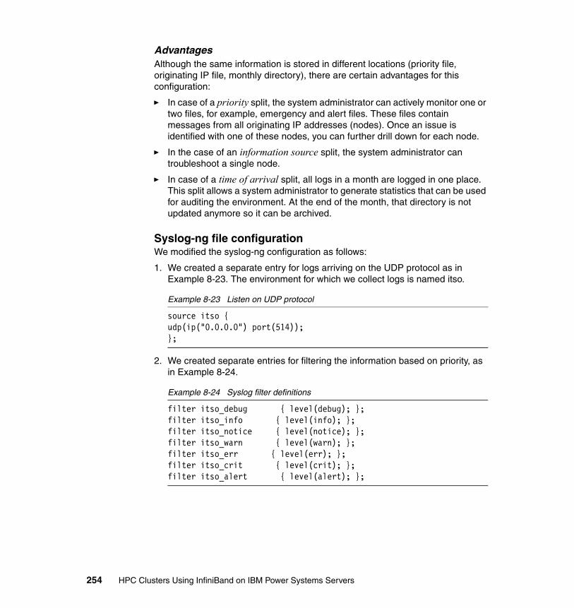
Advantages Although the same information is stored in different locations (priority file, originating IP file, monthly directory), there are certain advantages for this configuration:
� In case of a priority split, the system administrator can actively monitor one or two files, for example, emergency and alert files. These files contain messages from all originating IP addresses (nodes). Once an issue is identified with one of these nodes, you can further drill down for each node.
� In the case of an information source split, the system administrator can troubleshoot a single node.
� In case of a time of arrival split, all logs in a month are logged in one place. This split allows a system administrator to generate statistics that can be used for auditing the environment. At the end of the month, that directory is not updated anymore so it can be archived.
Syslog-ng file configuration We modified the syslog-ng configuration as follows:
1. We created a separate entry for logs arriving on the UDP protocol as in Example 8-23. The environment for which we collect logs is named itso.
Example 8-23 Listen on UDP protocol
source itso {udp(ip("0.0.0.0") port(514));};
2. We created separate entries for filtering the information based on priority, as in Example 8-24.
Example 8-24 Syslog filter definitions
filter itso_debug { level(debug); };filter itso_info { level(info); };filter itso_notice { level(notice); };filter itso_warn { level(warn); };filter itso_err { level(err); };filter itso_crit { level(crit); };filter itso_alert { level(alert); };
254 HPC Clusters Using InfiniBand on IBM Power Systems Servers

3. We defined destination files for each priority, originating IP (host source), and monthly split, as shown in Example 8-25.
Example 8-25 Syslog destination definitions
destination itso_debug { file ("/var/log/syslog/$R_MONTH/debug.file"); };destination itso_info { file ("/var/log/syslog/$R_MONTH/info.file"); };destination itso_notice { file\ ("/var/log/syslog/$R_MONTH/notice.file"); };destination itso_warn { file ("/var/log/syslog/$R_MONTH/warn.file"); };destination itso_err { file ("/var/log/syslog/$R_MONTH/err.file"); };destination itso_crit { file ("/var/log/syslog/$R_MONTH/crit.file"); };destination itso_alert { file\ ("/var/log/syslog/$R_MONTH/alert.file"); };destination itso_host { file\ ("/var/log/syslog/$R_MONTH/hosts/$HOST" template ("$DATE\ <$FACILITY.$PRIORITY> $MSG\n") template_escape(no)); };
4. We associated the message source filter types (Example 8-24 on page 254) with their destinations (Example 8-25), as shown in Example 8-26.
Example 8-26 Log routing
log { source (itso); destination (itso_host);};log { source (itso); filter (itso_debug);destination (itso_debug);};log { source (itso); filter (itso_info);destination (itso_info);};log { source (itso); filter (itso_notice);destination\ (itso_notice);};log { source (itso); filter (itso_warn);destination (itso_warn);};log { source (itso); filter (itso_err);destination (itso_err);};log { source (itso); filter (itso_crit);destination (itso_crit);};log { source (itso); filter (itso_alert);destination (itso_alert);};
After restarting the syslog daemon, all the logs arriving from the compute nodes should be located in /var/log/<MONTH>/.
Chapter 8. Configuring InfiniBand on Linux on Power 255
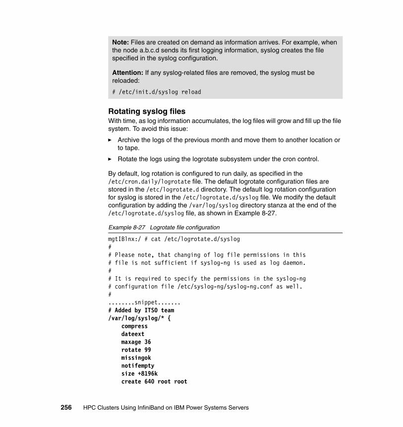
Rotating syslog filesWith time, as log information accumulates, the log files will grow and fill up the file system. To avoid this issue:
� Archive the logs of the previous month and move them to another location or to tape.
� Rotate the logs using the logrotate subsystem under the cron control.
By default, log rotation is configured to run daily, as specified in the /etc/cron.daily/logrotate file. The default logrotate configuration files are stored in the /etc/logrotate.d directory. The default log rotation configuration for syslog is stored in the /etc/logrotate.d/syslog file. We modify the default configuration by adding the /var/log/syslog directory stanza at the end of the /etc/logrotate.d/syslog file, as shown in Example 8-27.
Example 8-27 Logrotate file configuration
mgtIBlnx:/ # cat /etc/logrotate.d/syslog## Please note, that changing of log file permissions in this# file is not sufficient if syslog-ng is used as log daemon.## It is required to specify the permissions in the syslog-ng# configuration file /etc/syslog-ng/syslog-ng.conf as well.#........snippet.......# Added by ITSO team/var/log/syslog/* { compress dateext maxage 36 rotate 99 missingok notifempty size +8196k create 640 root root
Note: Files are created on demand as information arrives. For example, when the node a.b.c.d sends its first logging information, syslog creates the file specified in the syslog configuration.
Attention: If any syslog-related files are removed, the syslog must be reloaded:
# /etc/init.d/syslog reload
256 HPC Clusters Using InfiniBand on IBM Power Systems Servers
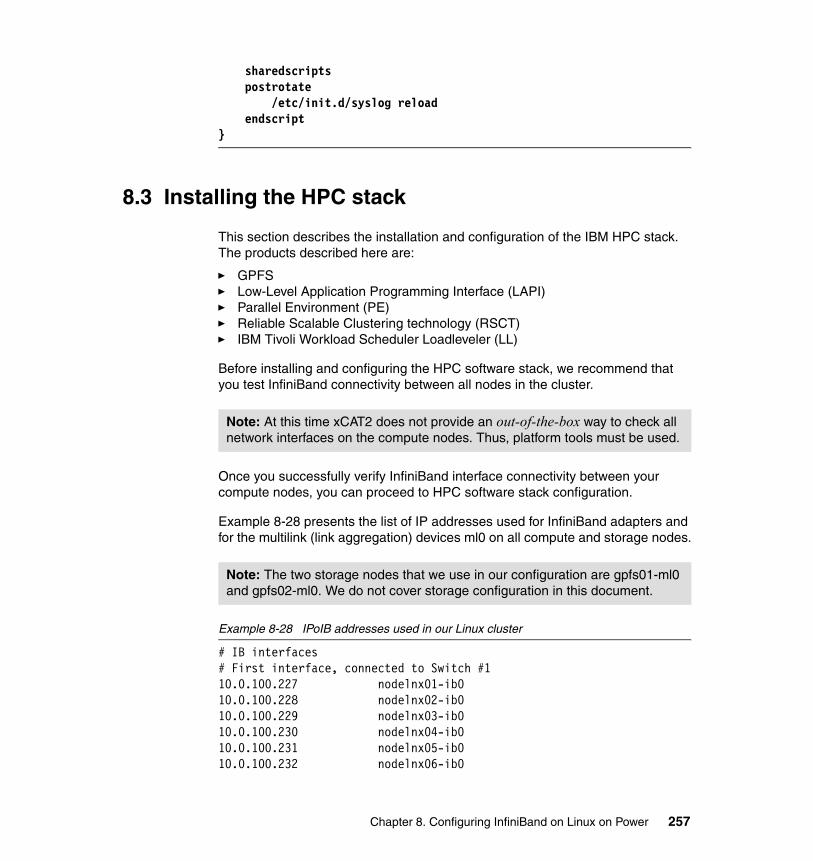
sharedscripts postrotate /etc/init.d/syslog reload endscript}
8.3 Installing the HPC stack
This section describes the installation and configuration of the IBM HPC stack. The products described here are:
� GPFS� Low-Level Application Programming Interface (LAPI)� Parallel Environment (PE)� Reliable Scalable Clustering technology (RSCT)� IBM Tivoli Workload Scheduler Loadleveler (LL)
Before installing and configuring the HPC software stack, we recommend that you test InfiniBand connectivity between all nodes in the cluster.
Once you successfully verify InfiniBand interface connectivity between your compute nodes, you can proceed to HPC software stack configuration.
Example 8-28 presents the list of IP addresses used for InfiniBand adapters and for the multilink (link aggregation) devices ml0 on all compute and storage nodes.
Example 8-28 IPoIB addresses used in our Linux cluster
# IB interfaces# First interface, connected to Switch #110.0.100.227 nodelnx01-ib010.0.100.228 nodelnx02-ib010.0.100.229 nodelnx03-ib010.0.100.230 nodelnx04-ib010.0.100.231 nodelnx05-ib010.0.100.232 nodelnx06-ib0
Note: At this time xCAT2 does not provide an out-of-the-box way to check all network interfaces on the compute nodes. Thus, platform tools must be used.
Note: The two storage nodes that we use in our configuration are gpfs01-ml0 and gpfs02-ml0. We do not cover storage configuration in this document.
Chapter 8. Configuring InfiniBand on Linux on Power 257
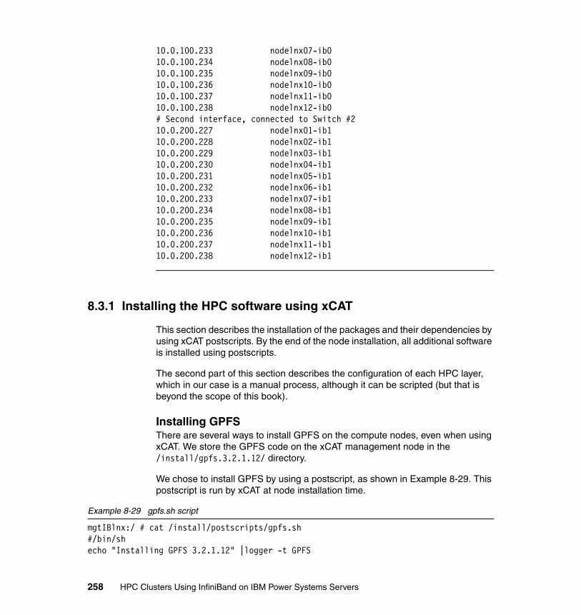
10.0.100.233 nodelnx07-ib010.0.100.234 nodelnx08-ib010.0.100.235 nodelnx09-ib010.0.100.236 nodelnx10-ib010.0.100.237 nodelnx11-ib010.0.100.238 nodelnx12-ib0# Second interface, connected to Switch #210.0.200.227 nodelnx01-ib110.0.200.228 nodelnx02-ib110.0.200.229 nodelnx03-ib110.0.200.230 nodelnx04-ib110.0.200.231 nodelnx05-ib110.0.200.232 nodelnx06-ib110.0.200.233 nodelnx07-ib110.0.200.234 nodelnx08-ib110.0.200.235 nodelnx09-ib110.0.200.236 nodelnx10-ib110.0.200.237 nodelnx11-ib110.0.200.238 nodelnx12-ib1
8.3.1 Installing the HPC software using xCAT
This section describes the installation of the packages and their dependencies by using xCAT postscripts. By the end of the node installation, all additional software is installed using postscripts.
The second part of this section describes the configuration of each HPC layer, which in our case is a manual process, although it can be scripted (but that is beyond the scope of this book).
Installing GPFS There are several ways to install GPFS on the compute nodes, even when using xCAT. We store the GPFS code on the xCAT management node in the /install/gpfs.3.2.1.12/ directory.
We chose to install GPFS by using a postscript, as shown in Example 8-29. This postscript is run by xCAT at node installation time.
Example 8-29 gpfs.sh script
mgtIBlnx:/ # cat /install/postscripts/gpfs.sh#/bin/shecho "Installing GPFS 3.2.1.12" |logger -t GPFS
258 HPC Clusters Using InfiniBand on IBM Power Systems Servers
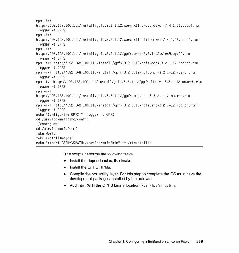
rpm -ivh http://192.168.100.111/install/gpfs.3.2.1.12/xorg-x11-proto-devel-7.4-1.21.ppc64.rpm |logger -t GPFSrpm -ivh http://192.168.100.111/install/gpfs.3.2.1.12/xorg-x11-util-devel-7.4-1.15.ppc64.rpm |logger -t GPFSrpm -ivh http://192.168.100.111/install/gpfs.3.2.1.12/gpfs.base-3.2.1-12.sles9.ppc64.rpm |logger -t GPFSrpm -ivh http://192.168.100.111/install/gpfs.3.2.1.12/gpfs.docs-3.2.1-12.noarch.rpm |logger -t GPFSrpm -ivh http://192.168.100.111/install/gpfs.3.2.1.12/gpfs.gpl-3.2.1-12.noarch.rpm |logger -t GPFSrpm -ivh http://192.168.100.111/install/gpfs.3.2.1.12/gpfs.libsrc-3.2.1-12.noarch.rpm |logger -t GPFSrpm -ivh http://192.168.100.111/install/gpfs.3.2.1.12/gpfs.msg.en_US-3.2.1-12.noarch.rpm |logger -t GPFSrpm -ivh http://192.168.100.111/install/gpfs.3.2.1.12/gpfs.src-3.2.1-12.noarch.rpm |logger -t GPFSecho "Configuring GPFS " |logger -t GPFScd /usr/lpp/mmfs/src/config./configurecd /usr/lpp/mmfs/src/make Worldmake InstallImagesecho "export PATH=\$PATH:/usr/lpp/mmfs/bin" >> /etc/profile
The scripts performs the following tasks:
� Install the dependencies, like imake.
� Install the GPFS RPMs,
� Compile the portability layer. For this step to complete the OS must have the development packages installed by the autoyast.
� Add into PATH the GPFS binary location, /usr/lpp/mmfs/bin.
Chapter 8. Configuring InfiniBand on Linux on Power 259
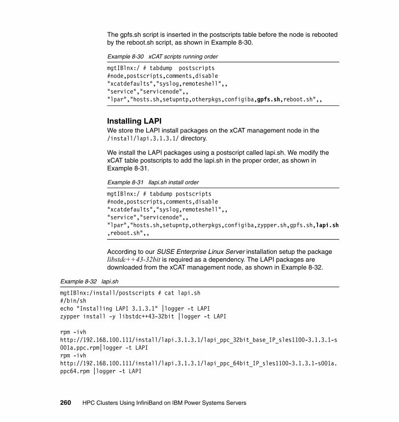
The gpfs.sh script is inserted in the postscripts table before the node is rebooted by the reboot.sh script, as shown in Example 8-30.
Example 8-30 xCAT scripts running order
mgtIBlnx:/ # tabdump postscripts#node,postscripts,comments,disable"xcatdefaults","syslog,remoteshell",,"service","servicenode",,"lpar","hosts.sh,setupntp,otherpkgs,configiba,gpfs.sh,reboot.sh",,
Installing LAPIWe store the LAPI install packages on the xCAT management node in the /install/lapi.3.1.3.1/ directory.
We install the LAPI packages using a postscript called lapi.sh. We modify the xCAT table postscripts to add the lapi.sh in the proper order, as shown in Example 8-31.
Example 8-31 llapi.sh install order
mgtIBlnx:/ # tabdump postscripts#node,postscripts,comments,disable"xcatdefaults","syslog,remoteshell",,"service","servicenode",,"lpar","hosts.sh,setupntp,otherpkgs,configiba,zypper.sh,gpfs.sh,lapi.sh,reboot.sh",,
According to our SUSE Enterprise Linux Server installation setup the package libstdc++43-32bit is required as a dependency. The LAPI packages are downloaded from the xCAT management node, as shown in Example 8-32.
Example 8-32 lapi.sh
mgtIBlnx:/install/postscripts # cat lapi.sh#/bin/shecho "Installing LAPI 3.1.3.1" |logger -t LAPIzypper install -y libstdc++43-32bit |logger -t LAPI
rpm -ivh http://192.168.100.111/install/lapi.3.1.3.1/lapi_ppc_32bit_base_IP_sles1100-3.1.3.1-s001a.ppc.rpm|logger -t LAPIrpm -ivh http://192.168.100.111/install/lapi.3.1.3.1/lapi_ppc_64bit_IP_sles1100-3.1.3.1-s001a.ppc64.rpm |logger -t LAPI
260 HPC Clusters Using InfiniBand on IBM Power Systems Servers
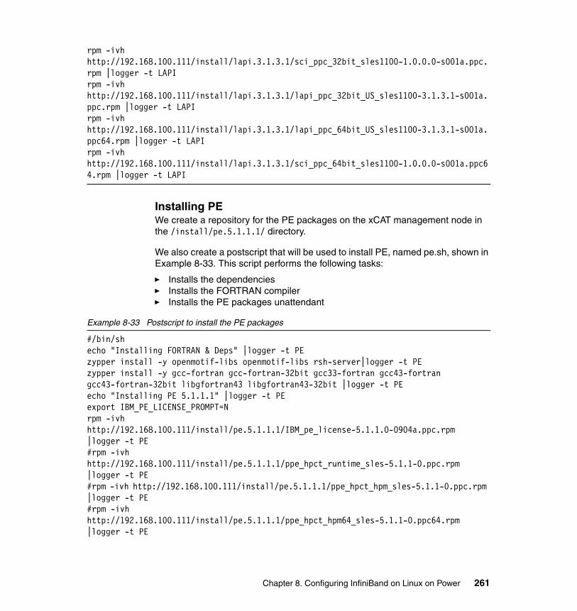
rpm -ivh http://192.168.100.111/install/lapi.3.1.3.1/sci_ppc_32bit_sles1100-1.0.0.0-s001a.ppc.rpm |logger -t LAPIrpm -ivh http://192.168.100.111/install/lapi.3.1.3.1/lapi_ppc_32bit_US_sles1100-3.1.3.1-s001a.ppc.rpm |logger -t LAPIrpm -ivh http://192.168.100.111/install/lapi.3.1.3.1/lapi_ppc_64bit_US_sles1100-3.1.3.1-s001a.ppc64.rpm |logger -t LAPIrpm -ivh http://192.168.100.111/install/lapi.3.1.3.1/sci_ppc_64bit_sles1100-1.0.0.0-s001a.ppc64.rpm |logger -t LAPI
Installing PEWe create a repository for the PE packages on the xCAT management node in the /install/pe.5.1.1.1/ directory.
We also create a postscript that will be used to install PE, named pe.sh, shown in Example 8-33. This script performs the following tasks:
� Installs the dependencies� Installs the FORTRAN compiler� Installs the PE packages unattendant
Example 8-33 Postscript to install the PE packages
#/bin/shecho "Installing FORTRAN & Deps" |logger -t PEzypper install -y openmotif-libs openmotif-libs rsh-server|logger -t PEzypper install -y gcc-fortran gcc-fortran-32bit gcc33-fortran gcc43-fortran gcc43-fortran-32bit libgfortran43 libgfortran43-32bit |logger -t PEecho "Installing PE 5.1.1.1" |logger -t PEexport IBM_PE_LICENSE_PROMPT=Nrpm -ivh http://192.168.100.111/install/pe.5.1.1.1/IBM_pe_license-5.1.1.0-0904a.ppc.rpm |logger -t PE#rpm -ivh http://192.168.100.111/install/pe.5.1.1.1/ppe_hpct_runtime_sles-5.1.1-0.ppc.rpm |logger -t PE#rpm -ivh http://192.168.100.111/install/pe.5.1.1.1/ppe_hpct_hpm_sles-5.1.1-0.ppc.rpm |logger -t PE#rpm -ivh http://192.168.100.111/install/pe.5.1.1.1/ppe_hpct_hpm64_sles-5.1.1-0.ppc64.rpm |logger -t PE
Chapter 8. Configuring InfiniBand on Linux on Power 261
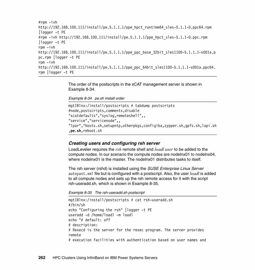
#rpm -ivh http://192.168.100.111/install/pe.5.1.1.1/ppe_hpct_runtime64_sles-5.1.1-0.ppc64.rpm |logger -t PE#rpm -ivh http://192.168.100.111/install/pe.5.1.1.1/ppe_hpct_sles-5.1.1-0.ppc.rpm |logger -t PErpm -ivh http://192.168.100.111/install/pe.5.1.1.1/ppe_ppc_base_32bit_sles1100-5.1.1.1-s001a.ppc.rpm |logger -t PErpm -ivh http://192.168.100.111/install/pe.5.1.1.1/ppe_ppc_64bit_sles1100-5.1.1.1-s001a.ppc64.rpm |logger -t PE
The order of the postscripts in the xCAT management server is shown in Example 8-34.
Example 8-34 pe.sh install order
mgtIBlnx:/install/postscripts # tabdump postscripts#node,postscripts,comments,disable"xcatdefaults","syslog,remoteshell",,"service","servicenode",,"lpar","hosts.sh,setupntp,otherpkgs,configiba,zypper.sh,gpfs.sh,lapi.sh,pe.sh,reboot.sh
Creating users and configuring rsh serverLoadLeveler requires the rsh remote shell and loadl user to be added to the compute nodes. In our scenario the compute nodes are nodelnx01 to nodelnx04, where nodelnx01 is the master. The nodelnx01 distributes tasks to itself.
The rsh server (rshd) is installed using the SUSE Enterprise Linux Server autoyast.xml file but is configured with a postscript. Also, the user loadl is added to all compute nodes and sets up the rsh remote access for it with the script rsh-useradd.sh, which is shown in Example 8-35.
Example 8-35 The rsh-useradd.sh postscript
mgtIBlnx:/install/postscripts # cat rsh-useradd.sh#/bin/shecho "Configuring the rsh" |logger -t PEuseradd -d /home/loadl -m loadlecho "# default: off# description:# Rexecd is the server for the rexec program. The server provides remote# execution facilities with authentication based on user names and
262 HPC Clusters Using InfiniBand on IBM Power Systems Servers
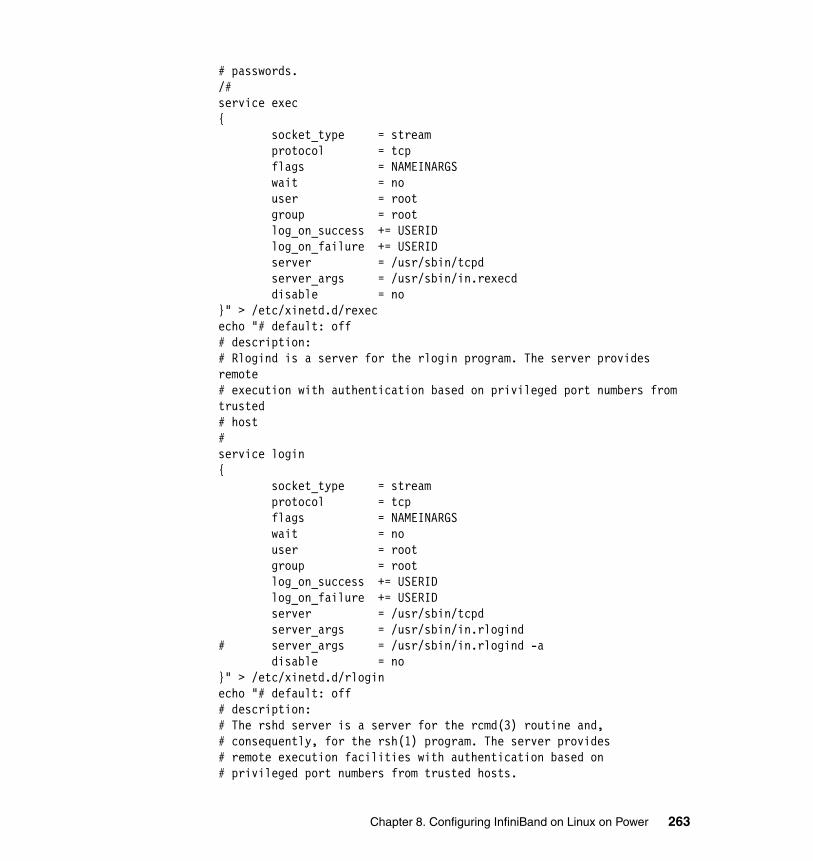
# passwords./#service exec{ socket_type = stream protocol = tcp flags = NAMEINARGS wait = no user = root group = root log_on_success += USERID log_on_failure += USERID server = /usr/sbin/tcpd server_args = /usr/sbin/in.rexecd disable = no}" > /etc/xinetd.d/rexececho "# default: off# description:# Rlogind is a server for the rlogin program. The server provides remote# execution with authentication based on privileged port numbers from trusted# host#service login{ socket_type = stream protocol = tcp flags = NAMEINARGS wait = no user = root group = root log_on_success += USERID log_on_failure += USERID server = /usr/sbin/tcpd server_args = /usr/sbin/in.rlogind# server_args = /usr/sbin/in.rlogind -a disable = no}" > /etc/xinetd.d/rloginecho "# default: off# description:# The rshd server is a server for the rcmd(3) routine and,# consequently, for the rsh(1) program. The server provides# remote execution facilities with authentication based on# privileged port numbers from trusted hosts.
Chapter 8. Configuring InfiniBand on Linux on Power 263
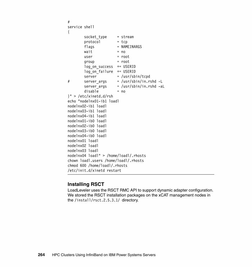
#service shell{ socket_type = stream protocol = tcp flags = NAMEINARGS wait = no user = root group = root log_on_success += USERID log_on_failure += USERID server = /usr/sbin/tcpd# server_args = /usr/sbin/in.rshd -L server_args = /usr/sbin/in.rshd -aL disable = no}" > /etc/xinetd.d/rshecho "nodelnx01-ib1 loadlnodelnx02-ib1 loadlnodelnx03-ib1 loadlnodelnx04-ib1 loadlnodelnx01-ib0 loadlnodelnx02-ib0 loadlnodelnx03-ib0 loadlnodelnx04-ib0 loadlnodelnx01 loadlnodelnx02 loadlnodelnx03 loadlnodelnx04 loadl" > /home/loadl/.rhostschown loadl.users /home/loadl/.rhostschmod 600 /home/loadl/.rhosts/etc/init.d/xinetd restart
Installing RSCTLoadLeveler uses the RSCT RMC API to support dynamic adapter configuration. We stored the RSCT installation packages on the xCAT management nodes in the /install/rsct.2.5.3.1/ directory.
264 HPC Clusters Using InfiniBand on IBM Power Systems Servers
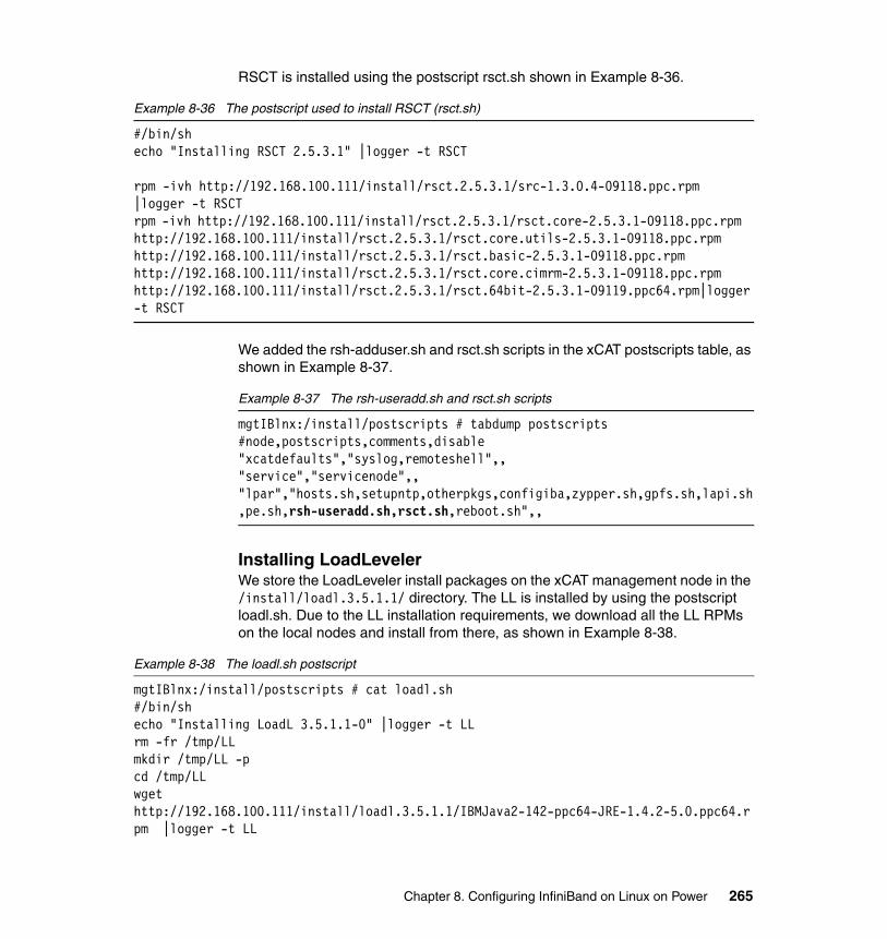
RSCT is installed using the postscript rsct.sh shown in Example 8-36.
Example 8-36 The postscript used to install RSCT (rsct.sh)
#/bin/shecho "Installing RSCT 2.5.3.1" |logger -t RSCT
rpm -ivh http://192.168.100.111/install/rsct.2.5.3.1/src-1.3.0.4-09118.ppc.rpm |logger -t RSCTrpm -ivh http://192.168.100.111/install/rsct.2.5.3.1/rsct.core-2.5.3.1-09118.ppc.rpm http://192.168.100.111/install/rsct.2.5.3.1/rsct.core.utils-2.5.3.1-09118.ppc.rpm http://192.168.100.111/install/rsct.2.5.3.1/rsct.basic-2.5.3.1-09118.ppc.rpm http://192.168.100.111/install/rsct.2.5.3.1/rsct.core.cimrm-2.5.3.1-09118.ppc.rpm http://192.168.100.111/install/rsct.2.5.3.1/rsct.64bit-2.5.3.1-09119.ppc64.rpm|logger -t RSCT
We added the rsh-adduser.sh and rsct.sh scripts in the xCAT postscripts table, as shown in Example 8-37.
Example 8-37 The rsh-useradd.sh and rsct.sh scripts
mgtIBlnx:/install/postscripts # tabdump postscripts#node,postscripts,comments,disable"xcatdefaults","syslog,remoteshell",,"service","servicenode",,"lpar","hosts.sh,setupntp,otherpkgs,configiba,zypper.sh,gpfs.sh,lapi.sh,pe.sh,rsh-useradd.sh,rsct.sh,reboot.sh",,
Installing LoadLevelerWe store the LoadLeveler install packages on the xCAT management node in the /install/loadl.3.5.1.1/ directory. The LL is installed by using the postscript loadl.sh. Due to the LL installation requirements, we download all the LL RPMs on the local nodes and install from there, as shown in Example 8-38.
Example 8-38 The loadl.sh postscript
mgtIBlnx:/install/postscripts # cat loadl.sh#/bin/shecho "Installing LoadL 3.5.1.1-0" |logger -t LLrm -fr /tmp/LLmkdir /tmp/LL -pcd /tmp/LLwget http://192.168.100.111/install/loadl.3.5.1.1/IBMJava2-142-ppc64-JRE-1.4.2-5.0.ppc64.rpm |logger -t LL
Chapter 8. Configuring InfiniBand on Linux on Power 265
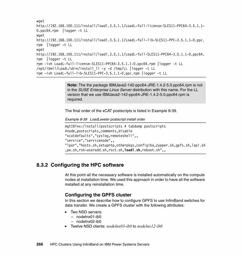
wget http://192.168.100.111/install/loadl.3.5.1.1/LoadL-full-license-SLES11-PPC64-3.5.1.1-0.ppc64.rpm |logger -t LLwget http://192.168.100.111/install/loadl.3.5.1.1/LoadL-full-lib-SLES11-PPC-3.5.1.1-0.ppc.rpm |logger -t LLwget http://192.168.100.111/install/loadl.3.5.1.1/LoadL-full-SLES11-PPC64-3.5.1.1-0.ppc64.rpm |logger -t LLrpm -ivh LoadL-full-license-SLES11-PPC64-3.5.1.1-0.ppc64.rpm |logger -t LL/opt/ibmll/LoadL/sbin/install_ll -y -d /tmp/LL |logger -t LLrpm -ivh LoadL-full-lib-SLES11-PPC-3.5.1.1-0.ppc.rpm |logger -t LL
The final order of the xCAT postscripts is listed in Example 8-39.
Example 8-39 LoadLeveler postscript install order
mgtIBlnx:/install/postscripts # tabdump postscripts#node,postscripts,comments,disable"xcatdefaults","syslog,remoteshell",,"service","servicenode",,"lpar","hosts.sh,setupntp,otherpkgs,configiba,zypper.sh,gpfs.sh,lapi.sh,pe.sh,rsh-useradd.sh,rsct.sh,loadl.sh,reboot.sh",,
8.3.2 Configuring the HPC software
At this point all the necessary software is installed automatically on the compute nodes at installation time. We used this approach in order to have all the software installed at any reinstallation time.
Configuring the GPFS clusterIn this section we describe how to configure GPFS to use InfiniBand switches for data transfer. We create a GPFS cluster with the following attributes:
� Two NSD servers:– nodelnx01-ib0 – nodelnx02-ib0
� Twelve NSD clients: nodelnx03-ib0 to nodelnx12-ib0
Note: The the package IBMJava2-142-ppc64-JRE-1.4.2-5.0.ppc64.rpm is not in the SUSE Enterprise Linux Server distribution with this name. For the LL version that we use IBMJava2-142-ppc64-JRE-1.4.2-5.0.ppc64.rpm is required.
266 HPC Clusters Using InfiniBand on IBM Power Systems Servers
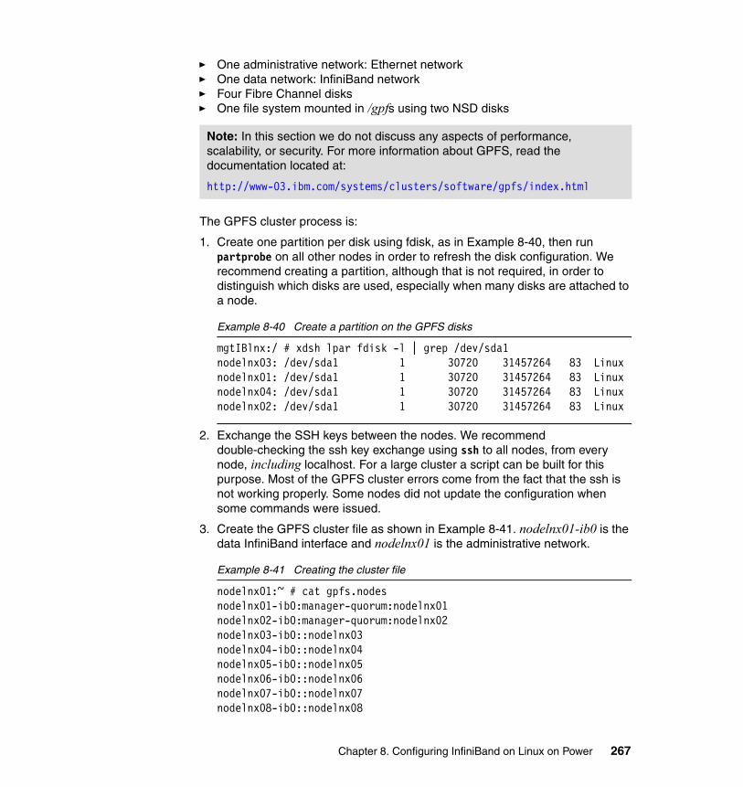
� One administrative network: Ethernet network� One data network: InfiniBand network� Four Fibre Channel disks� One file system mounted in /gpfs using two NSD disks
The GPFS cluster process is:
1. Create one partition per disk using fdisk, as in Example 8-40, then run partprobe on all other nodes in order to refresh the disk configuration. We recommend creating a partition, although that is not required, in order to distinguish which disks are used, especially when many disks are attached to a node.
Example 8-40 Create a partition on the GPFS disks
mgtIBlnx:/ # xdsh lpar fdisk -l | grep /dev/sda1nodelnx03: /dev/sda1 1 30720 31457264 83 Linuxnodelnx01: /dev/sda1 1 30720 31457264 83 Linuxnodelnx04: /dev/sda1 1 30720 31457264 83 Linuxnodelnx02: /dev/sda1 1 30720 31457264 83 Linux
2. Exchange the SSH keys between the nodes. We recommend double-checking the ssh key exchange using ssh to all nodes, from every node, including localhost. For a large cluster a script can be built for this purpose. Most of the GPFS cluster errors come from the fact that the ssh is not working properly. Some nodes did not update the configuration when some commands were issued.
3. Create the GPFS cluster file as shown in Example 8-41. nodelnx01-ib0 is the data InfiniBand interface and nodelnx01 is the administrative network.
Example 8-41 Creating the cluster file
nodelnx01:~ # cat gpfs.nodesnodelnx01-ib0:manager-quorum:nodelnx01nodelnx02-ib0:manager-quorum:nodelnx02nodelnx03-ib0::nodelnx03nodelnx04-ib0::nodelnx04nodelnx05-ib0::nodelnx05nodelnx06-ib0::nodelnx06nodelnx07-ib0::nodelnx07nodelnx08-ib0::nodelnx08
Note: In this section we do not discuss any aspects of performance, scalability, or security. For more information about GPFS, read the documentation located at:
http://www-03.ibm.com/systems/clusters/software/gpfs/index.html
Chapter 8. Configuring InfiniBand on Linux on Power 267
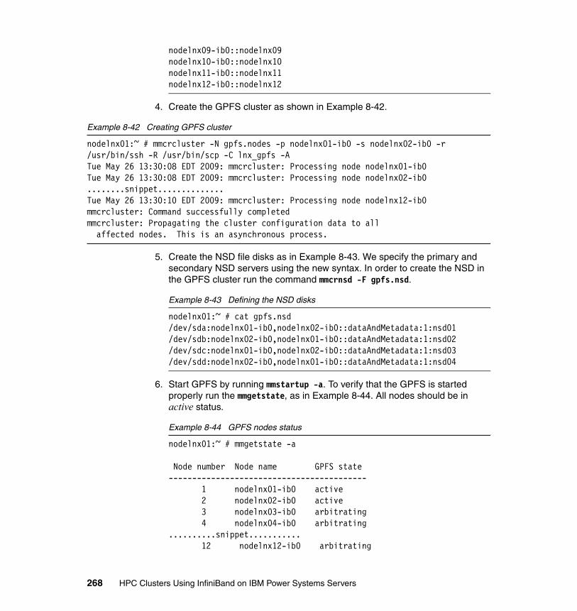
nodelnx09-ib0::nodelnx09nodelnx10-ib0::nodelnx10nodelnx11-ib0::nodelnx11nodelnx12-ib0::nodelnx12
4. Create the GPFS cluster as shown in Example 8-42.
Example 8-42 Creating GPFS cluster
nodelnx01:~ # mmcrcluster -N gpfs.nodes -p nodelnx01-ib0 -s nodelnx02-ib0 -r /usr/bin/ssh -R /usr/bin/scp -C lnx_gpfs -ATue May 26 13:30:08 EDT 2009: mmcrcluster: Processing node nodelnx01-ib0Tue May 26 13:30:08 EDT 2009: mmcrcluster: Processing node nodelnx02-ib0........snippet..............Tue May 26 13:30:10 EDT 2009: mmcrcluster: Processing node nodelnx12-ib0mmcrcluster: Command successfully completedmmcrcluster: Propagating the cluster configuration data to all affected nodes. This is an asynchronous process.
5. Create the NSD file disks as in Example 8-43. We specify the primary and secondary NSD servers using the new syntax. In order to create the NSD in the GPFS cluster run the command mmcrnsd -F gpfs.nsd.
Example 8-43 Defining the NSD disks
nodelnx01:~ # cat gpfs.nsd/dev/sda:nodelnx01-ib0,nodelnx02-ib0::dataAndMetadata:1:nsd01/dev/sdb:nodelnx02-ib0,nodelnx01-ib0::dataAndMetadata:1:nsd02/dev/sdc:nodelnx01-ib0,nodelnx02-ib0::dataAndMetadata:1:nsd03/dev/sdd:nodelnx02-ib0,nodelnx01-ib0::dataAndMetadata:1:nsd04
6. Start GPFS by running mmstartup -a. To verify that the GPFS is started properly run the mmgetstate, as in Example 8-44. All nodes should be in active status.
Example 8-44 GPFS nodes status
nodelnx01:~ # mmgetstate -a
Node number Node name GPFS state------------------------------------------ 1 nodelnx01-ib0 active 2 nodelnx02-ib0 active 3 nodelnx03-ib0 arbitrating 4 nodelnx04-ib0 arbitrating..........snippet...........
12 nodelnx12-ib0 arbitrating
268 HPC Clusters Using InfiniBand on IBM Power Systems Servers

nodelnx01:~ # mmgetstate -a
Node number Node name GPFS state------------------------------------------ 1 nodelnx01-ib0 active 2 nodelnx02-ib0 active 3 nodelnx03-ib0 active 4 nodelnx04-ib0 active.........snippet...........
12 nodelnx12-ib0 active
7. Create the GPFS file system, as shown in Example 8-45.
Example 8-45 GPFS: Creating the file system
nodelnx01:~ # mmcrfs /dev/gpfs -F gpfs.nsd -A yes -B 128K -M 2 -R 2 -T /gpfs
The following disks of gpfs will be formatted on node nodelnx01: nsd01: size 31457280 KB nsd02: size 31457280 KB nsd03: size 31457280 KB nsd04: size 31457280 KBFormatting file system ...Disks up to size 269 GB can be added to storage pool 'system'.Creating Inode FileCreating Allocation MapsClearing Inode Allocation MapClearing Block Allocation MapFormatting Allocation Map for storage pool 'system'Completed creation of file system /dev/gpfs.mmcrfs: Propagating the cluster configuration data to all affected nodes. This is an asynchronous process.
8. Mount the GPFS file system by running mmmount gpfs -a.
9. In our example the disks are available to all nodes due to the storage configuration. In order to use the InfiniBand network on the client nodes (nodelnx03 thru nodelnx12) we use the mount command as follows:
# mmmount /gpfs -o useNSDserver=always
Configuring RSCTLoadLeveler uses the RSCT RMC API to support dynamic adapter configuration if a machine stanza in the admin file does not contain any hardcoded adapters. You can also collect information about InfiniBand adapters by issuing the
Chapter 8. Configuring InfiniBand on Linux on Power 269
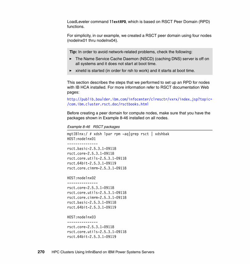
LoadLeveler command llextRPD, which is based on RSCT Peer Domain (RPD) functions.
For simplicity, in our example, we created a RSCT peer domain using four nodes (nodelnx01 thru nodelnx04).
This section describes the steps that we performed to set up an RPD for nodes with IB HCA installed. For more information refer to RSCT documentation Web pages:
http://publib.boulder.ibm.com/infocenter/clresctr/vxrx/index.jsp?topic=/com.ibm.cluster.rsct.doc/rsctbooks.html
Before creating a peer domain for compute nodes, make sure that you have the packages shown in Example 8-46 installed on all nodes.
Example 8-46 RSCT packages
mgtIBlnx:/ # xdsh lpar rpm -aq|grep rsct | xdshbakHOST:nodelnx01---------------rsct.basic-2.5.3.1-09118rsct.core-2.5.3.1-09118rsct.core.utils-2.5.3.1-09118rsct.64bit-2.5.3.1-09119rsct.core.cimrm-2.5.3.1-09118
HOST:nodelnx02---------------rsct.core-2.5.3.1-09118rsct.core.utils-2.5.3.1-09118rsct.core.cimrm-2.5.3.1-09118rsct.basic-2.5.3.1-09118rsct.64bit-2.5.3.1-09119
HOST:nodelnx03---------------rsct.core-2.5.3.1-09118rsct.core.utils-2.5.3.1-09118rsct.64bit-2.5.3.1-09119
Tip: In order to avoid network-related problems, check the following:
� The Name Service Cache Daemon (NSCD) (caching DNS) server is off on all systems and it does not start at boot time.
� xinetd is started (in order for rsh to work) and it starts at boot time.
270 HPC Clusters Using InfiniBand on IBM Power Systems Servers
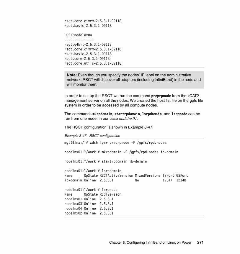
rsct.core.cimrm-2.5.3.1-09118rsct.basic-2.5.3.1-09118
HOST:nodelnx04---------------rsct.64bit-2.5.3.1-09119rsct.core.cimrm-2.5.3.1-09118rsct.basic-2.5.3.1-09118rsct.core-2.5.3.1-09118rsct.core.utils-2.5.3.1-09118
In order to set up the RSCT we run the command preprpnode from the xCAT2 management server on all the nodes. We created the host list file on the gpfs file system in order to be accessed by all compute nodes.
The commands mkrpdomain, startrpdomain, lsrpdomain, and lsrpnode can be run from one node, in our case nodelnx01.
The RSCT configuration is shown in Example 8-47.
Example 8-47 RSCT configuration
mgtIBlnx:/ # xdsh lpar preprpnode -F /gpfs/rpd.nodes
nodelnx01:~/work # mkrpdomain -F /gpfs/rpd.nodes ib-domain
nodelnx01:~/work # startrpdomain ib-domain
nodelnx01:~/work # lsrpdomainName OpState RSCTActiveVersion MixedVersions TSPort GSPortib-domain Online 2.5.3.1 No 12347 12348
nodelnx01:~/work # lsrpnodeName OpState RSCTVersionnodelnx01 Online 2.5.3.1nodelnx03 Online 2.5.3.1nodelnx04 Online 2.5.3.1nodelnx02 Online 2.5.3.1
Note: Even though you specify the nodes’ IP label on the administrative network, RSCT will discover all adapters (including InfiniBand) in the node and will monitor them.
Chapter 8. Configuring InfiniBand on Linux on Power 271

Configuring LoadLevelerWe use the following steps in order to configure the LoadLeveler:
1. LoadLeveler requires the loadl user for all compute nodes. This user is created with the rsh-useradd.sh script shown in Example 8-35 on page 262.
2. Create the /var/loadl directory and chown to the user loadl as in Example 8-48.
Example 8-48 Creating the directories for LoadLeveler
mgtIBlnx:/ # xdsh lpar mkdir /var/loadlmgtIBlnx:/ # xdsh lpar chown loadl.users /var/loadl
3. Set up the initial configuration as shown in Example 8-49. This is on one command line and is run from the xCAT management server. Note the quotation marks and double quotation marks.
Example 8-49 Configuring the LL configuration manager node
mgtIBlnx:/ # xdsh lpar 'su loadl -c "cd /opt/ibmll/LoadL/full/bin; ./llinit -local /var/loadl/ -release /opt/ibmll/LoadL/full -cm nodelnx01" '
4. Create a symlink for the home/loadl/bin:
# mgtIBlnx:/# xdsh lpar 'su loadl -c "rm -fr /home/loadl/bin; ln -s /opt/ibmll/LoadL/full/bin /home/loadl/bin"'
5. Using the command llextRPD, we extract the adapter information data from an RSCT peer domain to set up the administration file, as shown in Example 8-50.
Example 8-50 Output of command llextRPD
loadl@nodelnx01:~> llextRPD
#llextRPD: Cluster = "ib-domain" ID = "1RSqZ5qnp_x951dB~hvFZW" on Wed May 27 14:40:52 2009
nodelnx01: type = machine adapter_stanzas = nodelnx01 nodelnx01-ib1 nodelnx01-ib0 alias = nodelnx01-ib1 nodelnx01-ib0
nodelnx01: type = adapter
Note: Make sure that the UID and GID of the loadl user is the same on all nodes.
272 HPC Clusters Using InfiniBand on IBM Power Systems Servers
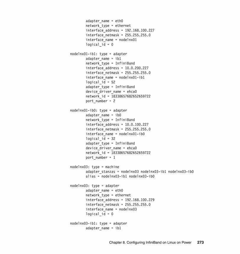
adapter_name = eth0 network_type = ethernet interface_address = 192.168.100.227 interface_netmask = 255.255.255.0 interface_name = nodelnx01 logical_id = 0
nodelnx01-ib1: type = adapter adapter_name = ib1 network_type = InfiniBand interface_address = 10.0.200.227 interface_netmask = 255.255.255.0 interface_name = nodelnx01-ib1 logical_id = 52 adapter_type = InfiniBand device_driver_name = ehca0 network_id = 18338657682652659722 port_number = 2
nodelnx01-ib0: type = adapter adapter_name = ib0 network_type = InfiniBand interface_address = 10.0.100.227 interface_netmask = 255.255.255.0 interface_name = nodelnx01-ib0 logical_id = 32 adapter_type = InfiniBand device_driver_name = ehca0 network_id = 18338657682652659722 port_number = 1
nodelnx03: type = machine adapter_stanzas = nodelnx03 nodelnx03-ib1 nodelnx03-ib0 alias = nodelnx03-ib1 nodelnx03-ib0
nodelnx03: type = adapter adapter_name = eth0 network_type = ethernet interface_address = 192.168.100.229 interface_netmask = 255.255.255.0 interface_name = nodelnx03 logical_id = 0
nodelnx03-ib1: type = adapter adapter_name = ib1
Chapter 8. Configuring InfiniBand on Linux on Power 273
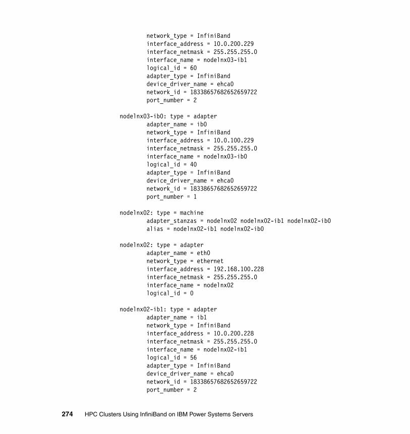
network_type = InfiniBand interface_address = 10.0.200.229 interface_netmask = 255.255.255.0 interface_name = nodelnx03-ib1 logical_id = 60 adapter_type = InfiniBand device_driver_name = ehca0 network_id = 18338657682652659722 port_number = 2
nodelnx03-ib0: type = adapter adapter_name = ib0 network_type = InfiniBand interface_address = 10.0.100.229 interface_netmask = 255.255.255.0 interface_name = nodelnx03-ib0 logical_id = 40 adapter_type = InfiniBand device_driver_name = ehca0 network_id = 18338657682652659722 port_number = 1
nodelnx02: type = machine adapter_stanzas = nodelnx02 nodelnx02-ib1 nodelnx02-ib0 alias = nodelnx02-ib1 nodelnx02-ib0
nodelnx02: type = adapter adapter_name = eth0 network_type = ethernet interface_address = 192.168.100.228 interface_netmask = 255.255.255.0 interface_name = nodelnx02 logical_id = 0
nodelnx02-ib1: type = adapter adapter_name = ib1 network_type = InfiniBand interface_address = 10.0.200.228 interface_netmask = 255.255.255.0 interface_name = nodelnx02-ib1 logical_id = 56 adapter_type = InfiniBand device_driver_name = ehca0 network_id = 18338657682652659722 port_number = 2
274 HPC Clusters Using InfiniBand on IBM Power Systems Servers
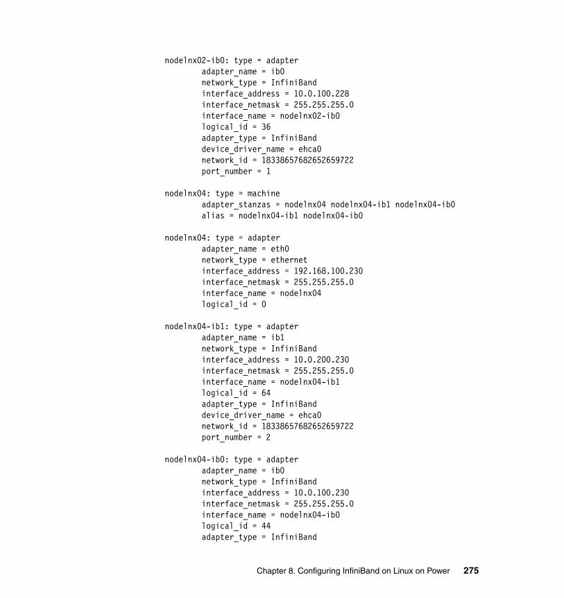
nodelnx02-ib0: type = adapter adapter_name = ib0 network_type = InfiniBand interface_address = 10.0.100.228 interface_netmask = 255.255.255.0 interface_name = nodelnx02-ib0 logical_id = 36 adapter_type = InfiniBand device_driver_name = ehca0 network_id = 18338657682652659722 port_number = 1
nodelnx04: type = machine adapter_stanzas = nodelnx04 nodelnx04-ib1 nodelnx04-ib0 alias = nodelnx04-ib1 nodelnx04-ib0
nodelnx04: type = adapter adapter_name = eth0 network_type = ethernet interface_address = 192.168.100.230 interface_netmask = 255.255.255.0 interface_name = nodelnx04 logical_id = 0
nodelnx04-ib1: type = adapter adapter_name = ib1 network_type = InfiniBand interface_address = 10.0.200.230 interface_netmask = 255.255.255.0 interface_name = nodelnx04-ib1 logical_id = 64 adapter_type = InfiniBand device_driver_name = ehca0 network_id = 18338657682652659722 port_number = 2
nodelnx04-ib0: type = adapter adapter_name = ib0 network_type = InfiniBand interface_address = 10.0.100.230 interface_netmask = 255.255.255.0 interface_name = nodelnx04-ib0 logical_id = 44 adapter_type = InfiniBand
Chapter 8. Configuring InfiniBand on Linux on Power 275
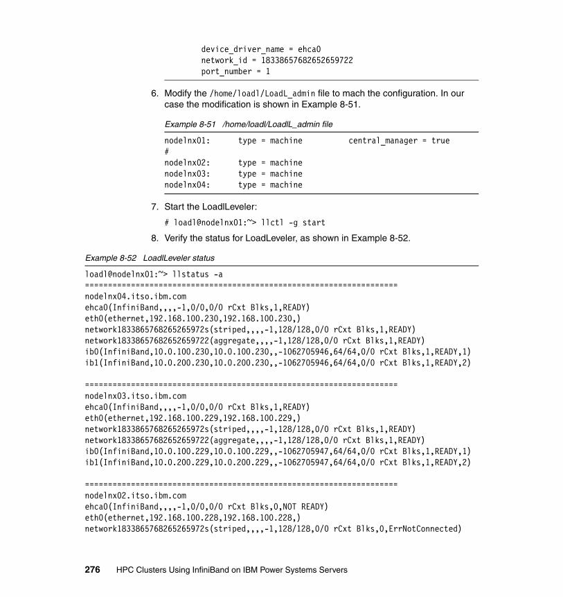
device_driver_name = ehca0 network_id = 18338657682652659722 port_number = 1
6. Modify the /home/loadl/LoadL_admin file to mach the configuration. In our case the modification is shown in Example 8-51.
Example 8-51 /home/loadl/LoadlL_admin file
nodelnx01: type = machine central_manager = true#nodelnx02: type = machinenodelnx03: type = machinenodelnx04: type = machine
7. Start the LoadlLeveler:
# loadl@nodelnx01:~> llctl -g start
8. Verify the status for LoadLeveler, as shown in Example 8-52.
Example 8-52 LoadlLeveler status
loadl@nodelnx01:~> llstatus -a====================================================================nodelnx04.itso.ibm.comehca0(InfiniBand,,,,-1,0/0,0/0 rCxt Blks,1,READY)eth0(ethernet,192.168.100.230,192.168.100.230,)network1833865768265265972s(striped,,,,-1,128/128,0/0 rCxt Blks,1,READY)network18338657682652659722(aggregate,,,,-1,128/128,0/0 rCxt Blks,1,READY)ib0(InfiniBand,10.0.100.230,10.0.100.230,,-1062705946,64/64,0/0 rCxt Blks,1,READY,1)ib1(InfiniBand,10.0.200.230,10.0.200.230,,-1062705946,64/64,0/0 rCxt Blks,1,READY,2)
====================================================================nodelnx03.itso.ibm.comehca0(InfiniBand,,,,-1,0/0,0/0 rCxt Blks,1,READY)eth0(ethernet,192.168.100.229,192.168.100.229,)network1833865768265265972s(striped,,,,-1,128/128,0/0 rCxt Blks,1,READY)network18338657682652659722(aggregate,,,,-1,128/128,0/0 rCxt Blks,1,READY)ib0(InfiniBand,10.0.100.229,10.0.100.229,,-1062705947,64/64,0/0 rCxt Blks,1,READY,1)ib1(InfiniBand,10.0.200.229,10.0.200.229,,-1062705947,64/64,0/0 rCxt Blks,1,READY,2)
====================================================================nodelnx02.itso.ibm.comehca0(InfiniBand,,,,-1,0/0,0/0 rCxt Blks,0,NOT READY)eth0(ethernet,192.168.100.228,192.168.100.228,)network1833865768265265972s(striped,,,,-1,128/128,0/0 rCxt Blks,0,ErrNotConnected)
276 HPC Clusters Using InfiniBand on IBM Power Systems Servers
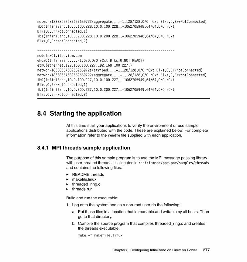
network18338657682652659722(aggregate,,,,-1,128/128,0/0 rCxt Blks,0,ErrNotConnected)ib0(InfiniBand,10.0.100.228,10.0.100.228,,-1062705948,64/64,0/0 rCxt Blks,0,ErrNotConnected,1)ib1(InfiniBand,10.0.200.228,10.0.200.228,,-1062705948,64/64,0/0 rCxt Blks,0,ErrNotConnected,2)
====================================================================nodelnx01.itso.ibm.comehca0(InfiniBand,,,,-1,0/0,0/0 rCxt Blks,0,NOT READY)eth0(ethernet,192.168.100.227,192.168.100.227,)network1833865768265265972s(striped,,,,-1,128/128,0/0 rCxt Blks,0,ErrNotConnected)network18338657682652659722(aggregate,,,,-1,128/128,0/0 rCxt Blks,0,ErrNotConnected)ib0(InfiniBand,10.0.100.227,10.0.100.227,,-1062705949,64/64,0/0 rCxt Blks,0,ErrNotConnected,1)ib1(InfiniBand,10.0.200.227,10.0.200.227,,-1062705949,64/64,0/0 rCxt Blks,0,ErrNotConnected,2)
8.4 Starting the application
At this time start your applications to verify the environment or use sample applications distributed with the code. These are explained below. For complete information refer to the readme file supplied with each application.
8.4.1 MPI threads sample application
The purpose of this sample program is to use the MPI message passing library with user-created threads. It is located in /opt/ibmhpc/ppe.poe/samples/threads and contains the following files:
� README.threads� makefile.linux� threaded_ring.c� threads.run
Build and run the executable:
1. Log onto the system and as a non-root user do the following:
a. Put these files in a location that is readable and writable by all hosts. Then go to that directory.
b. Compile the source program that compiles threaded_ring.c and creates the threads executable:
make -f makefile.linux
Chapter 8. Configuring InfiniBand on Linux on Power 277

2. Create a host file called host.list. Put one host per line with a minimum of two nodes.
3. Make sure that the nodes specified in the host.list file are initialized for the requested type of message passing.
4. Run the program. It has two inputs, ip and us. The ip option uses the UDP/IP library. The us option uses the user space library and is the default.
threads.run [{ip,us}]
5. If successful, the program should return the following from task 0:
TEST COMPLETE
8.4.2 Bandwidth sample application
The purpose of this sample program is to perform a point-to-point bandwidth measurement test. It is located in /opt/ibmhpc/ppe.poe/samples/poetest.bw and contains the following files:
� README.bw� bw.f� bw.run� makefile.linux
Build and run the executable:
1. Log onto the system and as a non-root user do the following:
a. Put these files in a location that is readable and writable by all hosts. Then go to that directory.
b. Compile the source program that compiles bw.f and creates the bw executable:
make -f makefile.linux
2. Create a host file called host.list with two entries. Put one host per line.
3. Run the program. It has two inputs, ip and us. The ip option is for IP message passing. The us option is for user-space message passing and is the default:
bw.run [{ip,us}]
4. If successful, the program should return the following:
Hello from node 0Hello from node 1MEASURED BANDWIDTH = ....... *10**6 Bytes/sec
Note: A FORTRAN compiler is required.
278 HPC Clusters Using InfiniBand on IBM Power Systems Servers
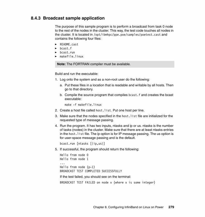
8.4.3 Broadcast sample application
The purpose of this sample program is to perform a broadcast from task 0 node to the rest of the nodes in the cluster. This way, the test code touches all nodes in the cluster. It is located in /opt/ibmhpc/ppe.poe/samples/poetest.cast and contains the following four files:
� README.cast� bcast.f� bcast.run � makefile.linux
Build and run the executable:
1. Log onto the system and as a non-root user do the following:
a. Put these files in a location that is readable and writable by all hosts. Then go to that directory.
b. Compile the source program that compiles bcast.f and creates the bcast executable:
make -f makefile.linux
2. Create a host file called host.list. Put one host per line.
3. Make sure that the nodes specified in the host.list file are initialized for the requested type of message passing.
4. Run the program. It has two inputs, ntasks and ip or us. ntasks is the number of tasks (nodes) in the cluster. Make sure that there are at least ntasks entries in the host.list file. The ip option is for IP message passing. The us option is for user-space message passing and is the default.
bcast.run [ntasks [{ip,us}]
5. If successful, the program should return the following:
Hello from node 0Hello from node 1...Hello from node (p-1)BROADCAST TEST COMPLETED SUCCESSFULLY
If the test failed, you should see on the terminal:
BROADCAST TEST FAILED on node x (where x is some integer)
Note: The FORTRAN compiler must be available.
Chapter 8. Configuring InfiniBand on Linux on Power 279
8.5 References
Refer to the following resources for more information:
� xCAT information related to SLES 11
http://xcat.wiki.sourceforge.net/SLES11.0+
� GPFS frequently asked questions
http://publib.boulder.ibm.com/infocenter/clresctr/vxrx/index.jsp?topic=/com.ibm.cluster.gpfs.doc/gpfs_faqs/gpfsclustersfaq.html
� GPFS documentation
http://publib.boulder.ibm.com/infocenter/clresctr/vxrx/index.jsp?topic=/com.ibm.cluster.gpfs.doc/gpfsbooks.html
� xCAT 2 Guide for the CSM System Administrator, REDP-44377
� Configuring and Managing AIX Clusters Using xCAT 2, SG24-77666
� xCAT documentation
https://xcat.svn.sourceforge.net/svnroot/xcat/xcat-core/trunk/xCAT-client/share/doc/
� NTP information
http://www.ntp.org
280 HPC Clusters Using InfiniBand on IBM Power Systems Servers
Part 4 Managing the InfiniBand environment
In this part we discuss InfiniBand system administration and problem determination tools and techniques. We describe common issues and explain how to resolved them, along with some methods for working with InfiniBand clusters and an introduction to InfiniBand monitoring.
Part 4
© Copyright IBM Corp. 2009. All rights reserved. 281

282 HPC Clusters Using InfiniBand on IBM Power Systems Servers
Chapter 9. Fabric management and monitoring
This chapter discusses a set of QLogic FastFabric Toolset commands that assist in the on-going management and monitoring of your fabric.
An introduction of commonly used commands will show the user how to use them in combination with one another to view topology and analyze and troubleshoot errors.
9
© Copyright IBM Corp. 2009. All rights reserved. 283
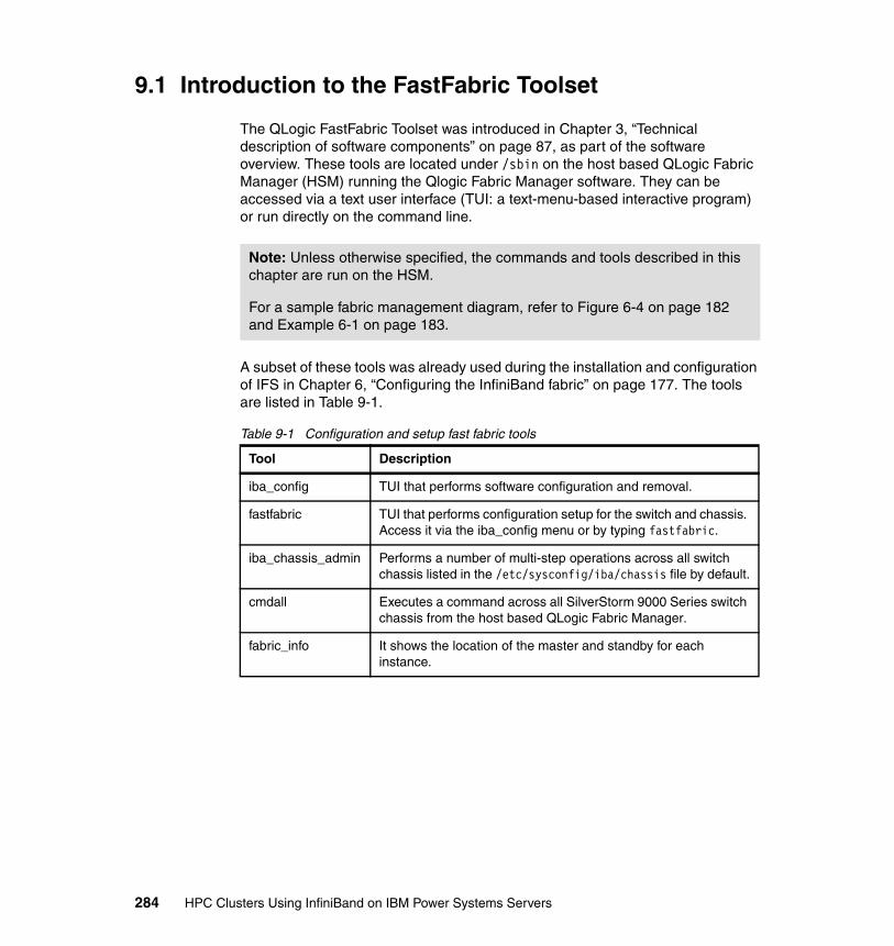
9.1 Introduction to the FastFabric Toolset
The QLogic FastFabric Toolset was introduced in Chapter 3, “Technical description of software components” on page 87, as part of the software overview. These tools are located under /sbin on the host based QLogic Fabric Manager (HSM) running the Qlogic Fabric Manager software. They can be accessed via a text user interface (TUI: a text-menu-based interactive program) or run directly on the command line.
A subset of these tools was already used during the installation and configuration of IFS in Chapter 6, “Configuring the InfiniBand fabric” on page 177. The tools are listed in Table 9-1.
Table 9-1 Configuration and setup fast fabric tools
Note: Unless otherwise specified, the commands and tools described in this chapter are run on the HSM.
For a sample fabric management diagram, refer to Figure 6-4 on page 182 and Example 6-1 on page 183.
Tool Description
iba_config TUI that performs software configuration and removal.
fastfabric TUI that performs configuration setup for the switch and chassis. Access it via the iba_config menu or by typing fastfabric.
iba_chassis_admin Performs a number of multi-step operations across all switch chassis listed in the /etc/sysconfig/iba/chassis file by default.
cmdall Executes a command across all SilverStorm 9000 Series switch chassis from the host based QLogic Fabric Manager.
fabric_info It shows the location of the master and standby for each instance.
284 HPC Clusters Using InfiniBand on IBM Power Systems Servers
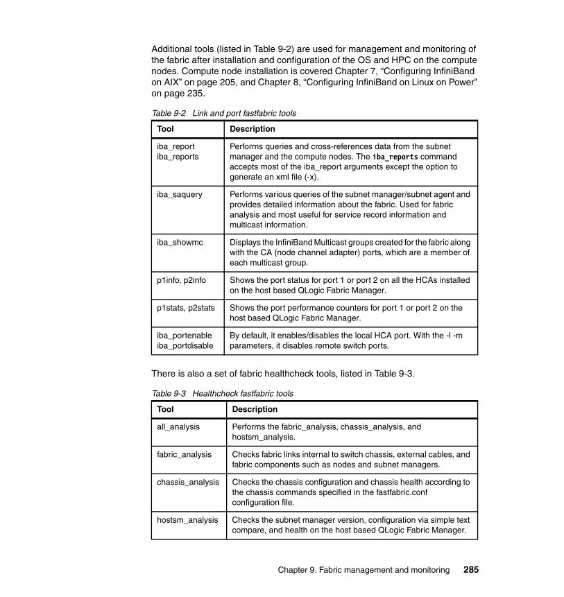
Additional tools (listed in Table 9-2) are used for management and monitoring of the fabric after installation and configuration of the OS and HPC on the compute nodes. Compute node installation is covered Chapter 7, “Configuring InfiniBand on AIX” on page 205, and Chapter 8, “Configuring InfiniBand on Linux on Power” on page 235.
Table 9-2 Link and port fastfabric tools
There is also a set of fabric healthcheck tools, listed in Table 9-3.
Table 9-3 Healthcheck fastfabric tools
Tool Description
iba_reportiba_reports
Performs queries and cross-references data from the subnet manager and the compute nodes. The iba_reports command accepts most of the iba_report arguments except the option to generate an xml file (-x).
iba_saquery Performs various queries of the subnet manager/subnet agent and provides detailed information about the fabric. Used for fabric analysis and most useful for service record information and multicast information.
iba_showmc Displays the InfiniBand Multicast groups created for the fabric along with the CA (node channel adapter) ports, which are a member of each multicast group.
p1info, p2info Shows the port status for port 1 or port 2 on all the HCAs installed on the host based QLogic Fabric Manager.
p1stats, p2stats Shows the port performance counters for port 1 or port 2 on the host based QLogic Fabric Manager.
iba_portenableiba_portdisable
By default, it enables/disables the local HCA port. With the -l -m parameters, it disables remote switch ports.
Tool Description
all_analysis Performs the fabric_analysis, chassis_analysis, and hostsm_analysis.
fabric_analysis Checks fabric links internal to switch chassis, external cables, and fabric components such as nodes and subnet managers.
chassis_analysis Checks the chassis configuration and chassis health according to the chassis commands specified in the fastfabric.conf configuration file.
hostsm_analysis Checks the subnet manager version, configuration via simple text compare, and health on the host based QLogic Fabric Manager.
Chapter 9. Fabric management and monitoring 285
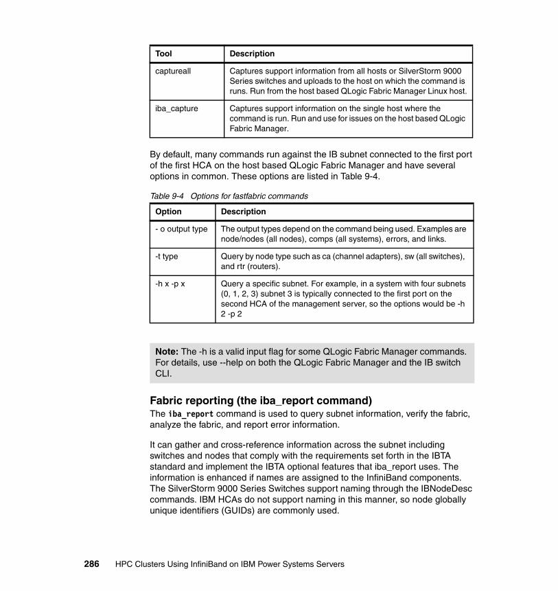
By default, many commands run against the IB subnet connected to the first port of the first HCA on the host based QLogic Fabric Manager and have several options in common. These options are listed in Table 9-4.
Table 9-4 Options for fastfabric commands
Fabric reporting (the iba_report command)The iba_report command is used to query subnet information, verify the fabric, analyze the fabric, and report error information.
It can gather and cross-reference information across the subnet including switches and nodes that comply with the requirements set forth in the IBTA standard and implement the IBTA optional features that iba_report uses. The information is enhanced if names are assigned to the InfiniBand components. The SilverStorm 9000 Series Switches support naming through the IBNodeDesc commands. IBM HCAs do not support naming in this manner, so node globally unique identifiers (GUIDs) are commonly used.
captureall Captures support information from all hosts or SilverStorm 9000 Series switches and uploads to the host on which the command is runs. Run from the host based QLogic Fabric Manager Linux host.
iba_capture Captures support information on the single host where the command is run. Run and use for issues on the host based QLogic Fabric Manager.
Option Description
- o output type The output types depend on the command being used. Examples are node/nodes (all nodes), comps (all systems), errors, and links.
-t type Query by node type such as ca (channel adapters), sw (all switches), and rtr (routers).
-h x -p x Query a specific subnet. For example, in a system with four subnets (0, 1, 2, 3) subnet 3 is typically connected to the first port on the second HCA of the management server, so the options would be -h 2 -p 2
Note: The -h is a valid input flag for some QLogic Fabric Manager commands. For details, use --help on both the QLogic Fabric Manager and the IB switch CLI.
Tool Description
286 HPC Clusters Using InfiniBand on IBM Power Systems Servers

This command has an extensive list of options and output types for generating hundreds of different reports. Topology reports include output types of nodes, comps (systems), links, and extlinks (external links). This can help verify or analyze your configuration. You can also analyze the operational characteristics for identifying bottlenecks or broken components. These output types include slow links (slowlinks), misconfigured links (misconfiglinks), and errors.
A key feature is the ability to focus the command when necessary, and also use global patterns to obtain a subset of information, such as for all switches. The focus option, -F, has a number of parameters to allow a wide array of focused reports. You can specify focus areas such as node type, name pattern, port rate, MTU, LID, or SM. This option gives a different view than a normal iba_report output.
For example, if a port is specified, only the node connected to that port will have information provided. You can focus on a node with the output type of links to get all the links associated with a node. You can even focus on a route between any two points and receive information about all the ports involved in that route. This gives you a way to drill down on performance issues or errors between two ports.
The focus is a requirement for certain commands so that the commands will ignore the Logical Host Channel Adapter (LHCA) to Logical Switch (SW) links that are internal to the IBM G+/G++ HCAs. Any errors on these internal links are not defined within the InfiniBand architecture. Therefore, these errors are not analyzed via iba_report. Here are some examples of iba_report commands that require this filter:
# iba_reports -o errors -F "nodepat:ib*" -q | grep -v Node:# iba_report -C -a -o errors -h 2 -p 1-F "nodepat:ib*"# iba_report -s -h 2 -p 1 -F "nodepat:ib*" -q
The output from iba_report can also be formatted in eXtended Markup Language (XML). The -x option converts the command output to XML format, which can be saved to a file. You can then customize the XML report file to include items like cable length, labels, and node descriptions. The augmented file then can be used with the input-topology option, -T, when running iba_report to help identify cluster information that cannot be obtained via subnet queries. The XML output can also be imported in a Microsoft® Excel spreadsheet by using the command xml_extract with iba_report. There are also related sample scripts such as iba_extract_perf, iba_extract_errors, and so on, which can be edited to add appropriate focus arguments.
Chapter 9. Fabric management and monitoring 287
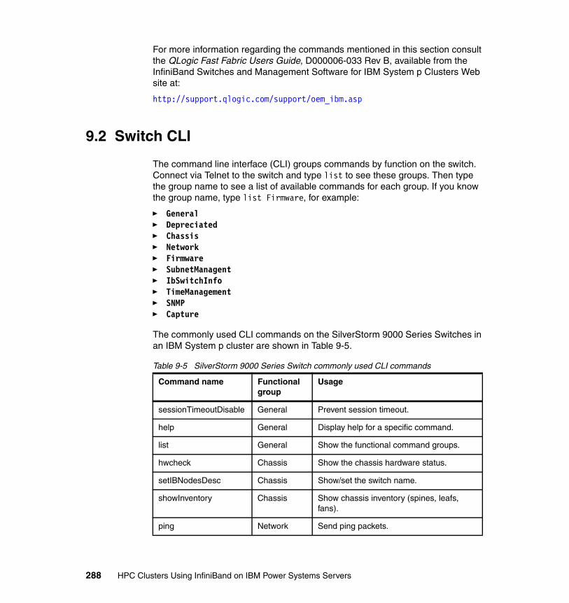
For more information regarding the commands mentioned in this section consult the QLogic Fast Fabric Users Guide, D000006-033 Rev B, available from the InfiniBand Switches and Management Software for IBM System p Clusters Web site at:
http://support.qlogic.com/support/oem_ibm.asp
9.2 Switch CLI
The command line interface (CLI) groups commands by function on the switch. Connect via Telnet to the switch and type list to see these groups. Then type the group name to see a list of available commands for each group. If you know the group name, type list Firmware, for example:
� General� Depreciated� Chassis� Network� Firmware� SubnetManagent� IbSwitchInfo� TimeManagement� SNMP� Capture
The commonly used CLI commands on the SilverStorm 9000 Series Switches in an IBM System p cluster are shown in Table 9-5.
Table 9-5 SilverStorm 9000 Series Switch commonly used CLI commands
Command name Functional group
Usage
sessionTimeoutDisable General Prevent session timeout.
help General Display help for a specific command.
list General Show the functional command groups.
hwcheck Chassis Show the chassis hardware status.
setIBNodesDesc Chassis Show/set the switch name.
showInventory Chassis Show chassis inventory (spines, leafs, fans).
ping Network Send ping packets.
288 HPC Clusters Using InfiniBand on IBM Power Systems Servers
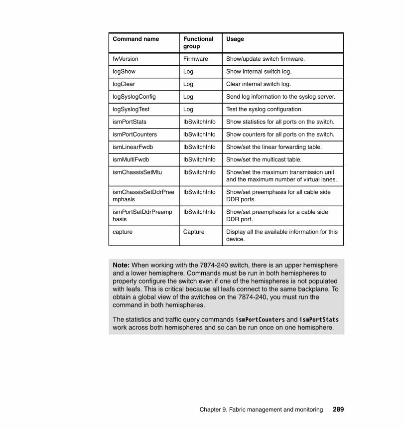
fwVersion Firmware Show/update switch firmware.
logShow Log Show internal switch log.
logClear Log Clear internal switch log.
logSyslogConfig Log Send log information to the syslog server.
logSyslogTest Log Test the syslog configuration.
ismPortStats IbSwitchInfo Show statistics for all ports on the switch.
ismPortCounters IbSwitchInfo Show counters for all ports on the switch.
ismLinearFwdb IbSwitchInfo Show/set the linear forwarding table.
ismMultiFwdb IbSwitchInfo Show/set the multicast table.
ismChassisSetMtu IbSwitchInfo Show/set the maximum transmission unit and the maximum number of virtual lanes.
ismChassisSetDdrPreemphasis
IbSwitchInfo Show/set preemphasis for all cable side DDR ports.
ismPortSetDdrPreemphasis
IbSwitchInfo Show/set preemphasis for a cable side DDR port.
capture Capture Display all the available information for this device.
Note: When working with the 7874-240 switch, there is an upper hemisphere and a lower hemisphere. Commands must be run in both hemispheres to properly configure the switch even if one of the hemispheres is not populated with leafs. This is critical because all leafs connect to the same backplane. To obtain a global view of the switches on the 7874-240, you must run the command in both hemispheres.
The statistics and traffic query commands ismPortCounters and ismPortStats work across both hemispheres and so can be run once on one hemisphere.
Command name Functional group
Usage
Chapter 9. Fabric management and monitoring 289
For more information regarding the SilverStorm 9000 Series Switch commands and Chassis Viewer consult the Silver Storm 9000 Users Guide, D000003-016 Rev A, and the Silver Storm 9000 CLI Reference Guide, D000025-001 Rev A, available from the InfiniBand Switches and Management Software for IBM System p Clusters Web site at:
http://support.qlogic.com/support/oem_ibm.asp
9.3 Fast Fabric analysis example
This section uses the QLogic FastFabric Toolset to analyze the scenario environment presented in Chapter 5, “Implementation overview” on page 161, that was set up and used in Chapter 6, “Configuring the InfiniBand fabric” on page 177, Chapter 7, “Configuring InfiniBand on AIX” on page 205, and Chapter 8, “Configuring InfiniBand on Linux on Power” on page 235. These tools and techniques can be used in addition to hardware tools like Service Focal Point on the HMC, and error logs on the compute nodes and xCAT management server.
9.3.1 Mapping devices
The QLogic FastFabric Toolset output and representation of the data is a literal translation of the IBTA architecture. While the QLogic FastFabric Toolset provides powerful analysis and the ability to extensively cross-reference fabric data, it still requires a deep dive into the details to understand and manage the fabric.
Mapping HCA GUIDs to the physical HCAs was briefly introduced in 2.3, “Host channel adapter” on page 67. In this section we also demonstrate how to identify the GUIDs in the QLogic FastFabric Toolset output.
Start by using iba_reports to view all links in the fabric, including IBM GX+/GX++ HCAs, host based QLogic Fabric Manager HCAs, spines, and leafs. If any links are down or not functional, they will only be partially visible in this output. We recommend that before running this report, you should make sure that all inks are online and operational.
290 HPC Clusters Using InfiniBand on IBM Power Systems Servers
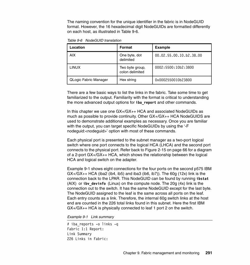
The naming convention for the unique identifier in the fabric is in NodeGUID format. However, the 16 hexadecimal digit NodeGUIDs are formatted differently on each host, as illustrated in Table 9-6.
Table 9-6 NodeGUID translation
There are a few basic ways to list the links in the fabric. Take some time to get familiarized to the output. Familiarity with the format is critical to understanding the more advanced output options for iba_report and other commands.
In this chapter we use one GX+/GX++ HCA and associated NodeGUIDs as much as possible to provide continuity. Other GX+/GX++ HCA NodeGUIDS are used to demonstrate additional examples as necessary. Once you are familiar with the output, you can target specific NodeGUIDs by using the ‘-F nodeguid:<nodeguid>’ option with most of these commands.
Each physical port is presented to the subnet manager as a two-port logical switch where one port connects to the logical HCA (LHCA) and the second port connects to the physical port. Refer back to Figure 2-15 on page 66 for a diagram of a 2-port GX+/GX++ HCA, which shows the relationship between the logical HCA and logical switch on the adapter.
Example 9-1 shows eight connections for the four ports on the second p575 IBM GX+/GX++ HCA (iba2 (ib4, ib5) and iba3 (ib6, ib7)). The 60g (12x) link is the connection back to the LPAR. This NodeGUID can be found by running ibstat (AIX) or ibv_devinfo (Linux) on the compute node. The 20g (4x) link is the connection out to the switch. It has the same NodeGUID except for the last byte. The NodeGUID assigned to the leaf is the same across all ports on the leaf. Each entry counts as a link. Therefore, the internal 60g switch links at the host end are counted in the 226 total links found in this subnet. Here the first IBM GX+/GX++ HCA is physically connected to leaf 1 port 2 on the switch.
Example 9-1 Link summary
# iba_reports -o links -qFabric 1:1 Report:Link Summary226 Links in Fabric:
Location Format Example
AIX One byte, dot delimited
00.02.55.00.10.b2.38.00
LINUX Two byte group, colon delimited
0002:5500:10b2:3800
QLogic Fabric Manager Hex string 0x0002550010b23800
Chapter 9. Fabric management and monitoring 291
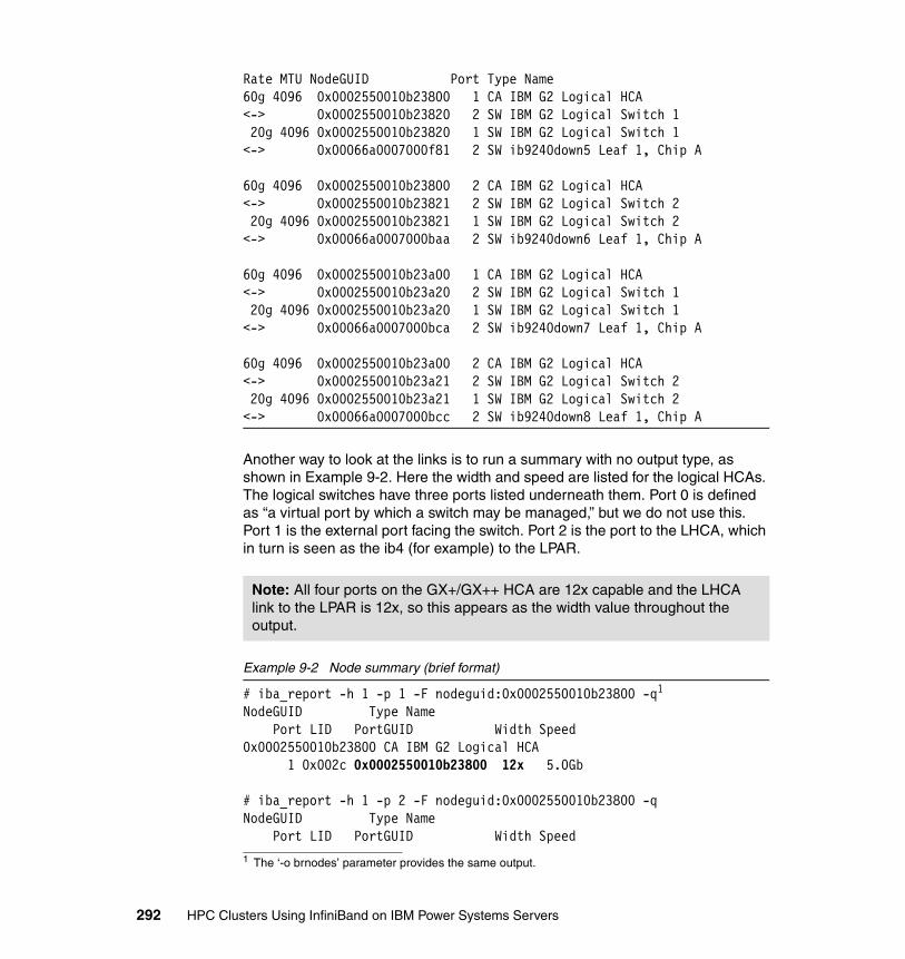
Rate MTU NodeGUID Port Type Name60g 4096 0x0002550010b23800 1 CA IBM G2 Logical HCA<-> 0x0002550010b23820 2 SW IBM G2 Logical Switch 1 20g 4096 0x0002550010b23820 1 SW IBM G2 Logical Switch 1<-> 0x00066a0007000f81 2 SW ib9240down5 Leaf 1, Chip A
60g 4096 0x0002550010b23800 2 CA IBM G2 Logical HCA<-> 0x0002550010b23821 2 SW IBM G2 Logical Switch 2 20g 4096 0x0002550010b23821 1 SW IBM G2 Logical Switch 2<-> 0x00066a0007000baa 2 SW ib9240down6 Leaf 1, Chip A
60g 4096 0x0002550010b23a00 1 CA IBM G2 Logical HCA<-> 0x0002550010b23a20 2 SW IBM G2 Logical Switch 1 20g 4096 0x0002550010b23a20 1 SW IBM G2 Logical Switch 1<-> 0x00066a0007000bca 2 SW ib9240down7 Leaf 1, Chip A
60g 4096 0x0002550010b23a00 2 CA IBM G2 Logical HCA<-> 0x0002550010b23a21 2 SW IBM G2 Logical Switch 2 20g 4096 0x0002550010b23a21 1 SW IBM G2 Logical Switch 2<-> 0x00066a0007000bcc 2 SW ib9240down8 Leaf 1, Chip A
Another way to look at the links is to run a summary with no output type, as shown in Example 9-2. Here the width and speed are listed for the logical HCAs. The logical switches have three ports listed underneath them. Port 0 is defined as “a virtual port by which a switch may be managed,” but we do not use this. Port 1 is the external port facing the switch. Port 2 is the port to the LHCA, which in turn is seen as the ib4 (for example) to the LPAR.
Example 9-2 Node summary (brief format)
# iba_report -h 1 -p 1 -F nodeguid:0x0002550010b23800 -q1
NodeGUID Type Name Port LID PortGUID Width Speed0x0002550010b23800 CA IBM G2 Logical HCA 1 0x002c 0x0002550010b23800 12x 5.0Gb
# iba_report -h 1 -p 2 -F nodeguid:0x0002550010b23800 -qNodeGUID Type Name Port LID PortGUID Width Speed
Note: All four ports on the GX+/GX++ HCA are 12x capable and the LHCA link to the LPAR is 12x, so this appears as the width value throughout the output.
1 The ‘-o brnodes’ parameter provides the same output.
292 HPC Clusters Using InfiniBand on IBM Power Systems Servers
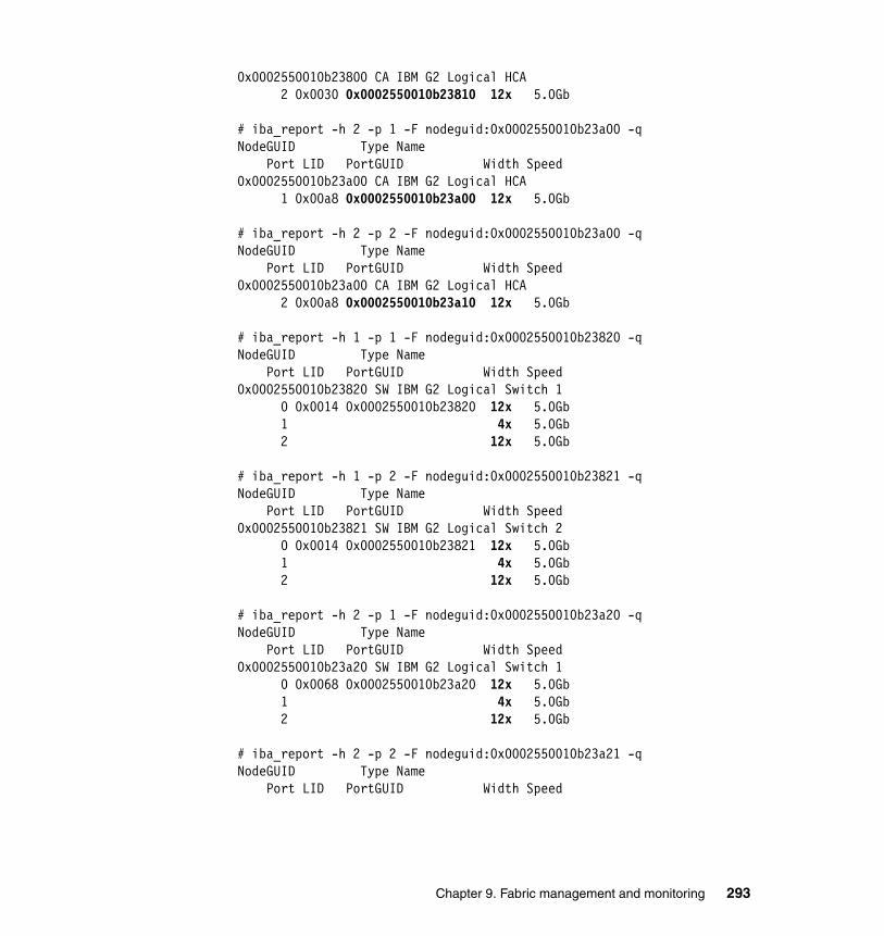
0x0002550010b23800 CA IBM G2 Logical HCA 2 0x0030 0x0002550010b23810 12x 5.0Gb
# iba_report -h 2 -p 1 -F nodeguid:0x0002550010b23a00 -qNodeGUID Type Name Port LID PortGUID Width Speed0x0002550010b23a00 CA IBM G2 Logical HCA 1 0x00a8 0x0002550010b23a00 12x 5.0Gb
# iba_report -h 2 -p 2 -F nodeguid:0x0002550010b23a00 -qNodeGUID Type Name Port LID PortGUID Width Speed0x0002550010b23a00 CA IBM G2 Logical HCA 2 0x00a8 0x0002550010b23a10 12x 5.0Gb
# iba_report -h 1 -p 1 -F nodeguid:0x0002550010b23820 -qNodeGUID Type Name Port LID PortGUID Width Speed0x0002550010b23820 SW IBM G2 Logical Switch 1 0 0x0014 0x0002550010b23820 12x 5.0Gb 1 4x 5.0Gb 2 12x 5.0Gb
# iba_report -h 1 -p 2 -F nodeguid:0x0002550010b23821 -qNodeGUID Type Name Port LID PortGUID Width Speed0x0002550010b23821 SW IBM G2 Logical Switch 2 0 0x0014 0x0002550010b23821 12x 5.0Gb 1 4x 5.0Gb 2 12x 5.0Gb
# iba_report -h 2 -p 1 -F nodeguid:0x0002550010b23a20 -qNodeGUID Type Name Port LID PortGUID Width Speed0x0002550010b23a20 SW IBM G2 Logical Switch 1 0 0x0068 0x0002550010b23a20 12x 5.0Gb 1 4x 5.0Gb 2 12x 5.0Gb
# iba_report -h 2 -p 2 -F nodeguid:0x0002550010b23a21 -qNodeGUID Type Name Port LID PortGUID Width Speed
Chapter 9. Fabric management and monitoring 293
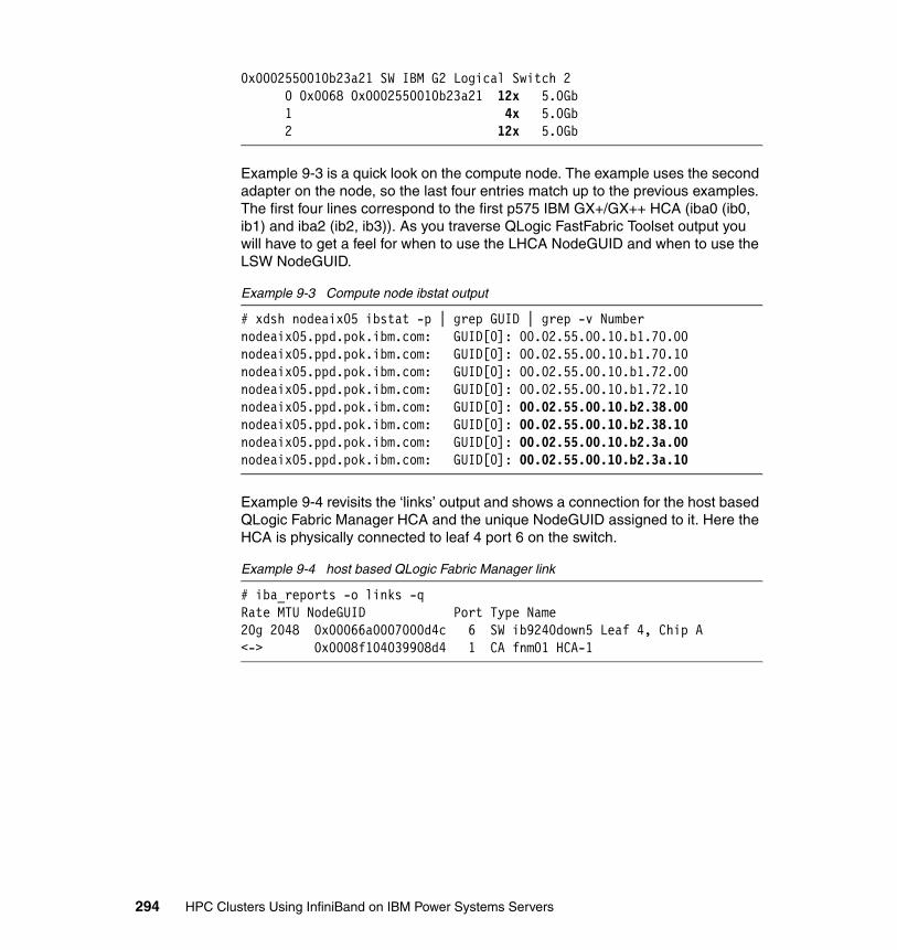
0x0002550010b23a21 SW IBM G2 Logical Switch 2 0 0x0068 0x0002550010b23a21 12x 5.0Gb 1 4x 5.0Gb 2 12x 5.0Gb
Example 9-3 is a quick look on the compute node. The example uses the second adapter on the node, so the last four entries match up to the previous examples. The first four lines correspond to the first p575 IBM GX+/GX++ HCA (iba0 (ib0, ib1) and iba2 (ib2, ib3)). As you traverse QLogic FastFabric Toolset output you will have to get a feel for when to use the LHCA NodeGUID and when to use the LSW NodeGUID.
Example 9-3 Compute node ibstat output
# xdsh nodeaix05 ibstat -p | grep GUID | grep -v Numbernodeaix05.ppd.pok.ibm.com: GUID[0]: 00.02.55.00.10.b1.70.00nodeaix05.ppd.pok.ibm.com: GUID[0]: 00.02.55.00.10.b1.70.10nodeaix05.ppd.pok.ibm.com: GUID[0]: 00.02.55.00.10.b1.72.00nodeaix05.ppd.pok.ibm.com: GUID[0]: 00.02.55.00.10.b1.72.10nodeaix05.ppd.pok.ibm.com: GUID[0]: 00.02.55.00.10.b2.38.00nodeaix05.ppd.pok.ibm.com: GUID[0]: 00.02.55.00.10.b2.38.10nodeaix05.ppd.pok.ibm.com: GUID[0]: 00.02.55.00.10.b2.3a.00nodeaix05.ppd.pok.ibm.com: GUID[0]: 00.02.55.00.10.b2.3a.10
Example 9-4 revisits the ‘links’ output and shows a connection for the host based QLogic Fabric Manager HCA and the unique NodeGUID assigned to it. Here the HCA is physically connected to leaf 4 port 6 on the switch.
Example 9-4 host based QLogic Fabric Manager link
# iba_reports -o links -qRate MTU NodeGUID Port Type Name20g 2048 0x00066a0007000d4c 6 SW ib9240down5 Leaf 4, Chip A<-> 0x0008f104039908d4 1 CA fnm01 HCA-1
294 HPC Clusters Using InfiniBand on IBM Power Systems Servers
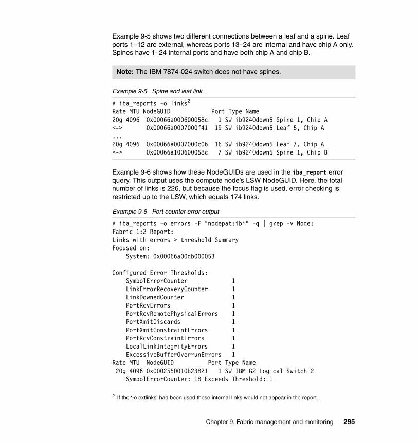
Example 9-5 shows two different connections between a leaf and a spine. Leaf ports 1–12 are external, whereas ports 13–24 are internal and have chip A only. Spines have 1–24 internal ports and have both chip A and chip B.
Example 9-5 Spine and leaf link
# iba_reports -o links2
Rate MTU NodeGUID Port Type Name20g 4096 0x00066a000600058c 1 SW ib9240down5 Spine 1, Chip A<-> 0x00066a0007000f41 19 SW ib9240down5 Leaf 5, Chip A...20g 4096 0x00066a0007000c06 16 SW ib9240down5 Leaf 7, Chip A<-> 0x00066a100600058c 7 SW ib9240down5 Spine 1, Chip B
Example 9-6 shows how these NodeGUIDs are used in the iba_report error query. This output uses the compute node’s LSW NodeGUID. Here, the total number of links is 226, but because the focus flag is used, error checking is restricted up to the LSW, which equals 174 links.
Example 9-6 Port counter error output
# iba_reports -o errors -F "nodepat:ib*" -q | grep -v Node: Fabric 1:2 Report:Links with errors > threshold SummaryFocused on: System: 0x00066a00db000053
Configured Error Thresholds: SymbolErrorCounter 1 LinkErrorRecoveryCounter 1 LinkDownedCounter 1 PortRcvErrors 1 PortRcvRemotePhysicalErrors 1 PortXmitDiscards 1 PortXmitConstraintErrors 1 PortRcvConstraintErrors 1 LocalLinkIntegrityErrors 1 ExcessiveBufferOverrunErrors 1Rate MTU NodeGUID Port Type Name 20g 4096 0x0002550010b23821 1 SW IBM G2 Logical Switch 2 SymbolErrorCounter: 18 Exceeds Threshold: 1
Note: The IBM 7874-024 switch does not have spines.
2 If the ‘-o extlinks’ had been used these internal links would not appear in the report.
Chapter 9. Fabric management and monitoring 295

LinkErrorRecoveryCounter: 48 Exceeds Threshold: 1<-> 0x00066a0007000baa 2 SW ib9240down5 Leaf 1, Chip A SymbolErrorCounter: 1911 Exceeds Threshold: 1 LinkErrorRecoveryCounter: 48 Exceeds Threshold: 1 PortRcvErrors: 11 Exceeds Threshold: 1174 of 226 Links Checked, 1 Errors found
Up to this point the only way to identify the node, adapter, and interface in the link or error output is to look it up on the node side using ibstat and ibv_devinfo or match up the switch side leaf port to a cable diagram.
There is a parameter for the iba_report command that will put the data into an XML file, which can then be referenced in future iba_report queries. This XML file can be updated to include additional node and cable information. Before issuing this command to capture the current topology, ensure that all links are online and operational.
#iba_report -o links -o brnodes -h 1 -p 1 -x > \> /etc/sysconfig/iba/topology.1:1.xml
This will allow NodeDetails to be added to the Nodes section of XML and CableDetails to be added to the Links section of XML. Repeat the previous command for other interfaces.
Example 9-7 shows two NodeDetail entries, one for each part of the switch on the GX+/GX++ HCA. Add your cable stanzas at the bottom of the file immediately before </Report>. One entry is for the internal 12x link on the adapter and the other is the 4x link to the switch. This should be a one-time update provided that the node hardware does not change frequently.
Example 9-7 Topology XML output
...<Nodes>
<CAs><Node id="0x0002550010b23800">
<NodeGUID>0x0002550010b23800</NodeGUID><NodeDesc>nodeaix05-ib5</NodeDesc><NodeDetails>nodeaix05-ib5</NodeDetails>
</Node><Node id="0x0002550010b23821">
<NodeGUID>0x00025500107c7000</NodeGUID><NodeDesc>nodeaix05-ib5</NodeDesc><NodeDetails>nodeaix05-ib5</NodeDetails>
</Node></CAs>
296 HPC Clusters Using InfiniBand on IBM Power Systems Servers
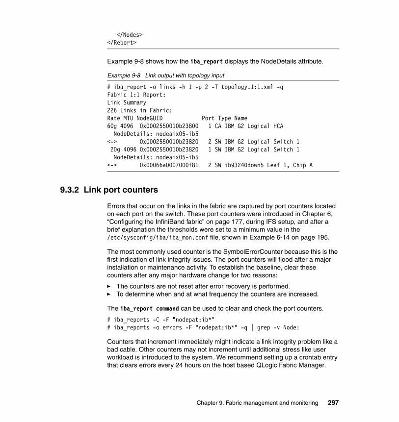
</Nodes></Report>
Example 9-8 shows how the iba_report displays the NodeDetails attribute.
Example 9-8 Link output with topology input
# iba_report -o links -h 1 -p 2 -T topology.1:1.xml -qFabric 1:1 Report:Link Summary226 Links in Fabric:Rate MTU NodeGUID Port Type Name60g 4096 0x0002550010b23800 1 CA IBM G2 Logical HCA
NodeDetails: nodeaix05-ib5<-> 0x0002550010b23820 2 SW IBM G2 Logical Switch 1 20g 4096 0x0002550010b23820 1 SW IBM G2 Logical Switch 1
NodeDetails: nodeaix05-ib5<-> 0x00066a0007000f81 2 SW ib93240down5 Leaf 1, Chip A
9.3.2 Link port counters
Errors that occur on the links in the fabric are captured by port counters located on each port on the switch. These port counters were introduced in Chapter 6, “Configuring the InfiniBand fabric” on page 177, during IFS setup, and after a brief explanation the thresholds were set to a minimum value in the /etc/sysconfig/iba/iba_mon.conf file, shown in Example 6-14 on page 195.
The most commonly used counter is the SymbolErrorCounter because this is the first indication of link integrity issues. The port counters will flood after a major installation or maintenance activity. To establish the baseline, clear these counters after any major hardware change for two reasons:
� The counters are not reset after error recovery is performed.� To determine when and at what frequency the counters are increased.
The iba_report command can be used to clear and check the port counters.
# iba_reports -C -F "nodepat:ib*"# iba_reports -o errors -F "nodepat:ib*" -q | grep -v Node:
Counters that increment immediately might indicate a link integrity problem like a bad cable. Other counters may not increment until additional stress like user workload is introduced to the system. We recommend setting up a crontab entry that clears errors every 24 hours on the host based QLogic Fabric Manager.
Chapter 9. Fabric management and monitoring 297
There are two main types of port counters:
� Link integrity � Congestion
Link integrity indicates a link quality issue. This could be a bad cable, loose connection, or other malfunctioning hardware. Congestion is caused by bottlenecks between any two points in the fabric. Refer to the Appendix B, “Fabric port counters” on page 381, for a detailed explanation of port counters.
Use fault isolation procedures to determine and correct errors on the fabric. The remainder of this section provides common techniques and examples from Chapter 5, “Implementation overview” on page 161. In most cases the counter is increased at the receiving end of the link. However, they can be seen at both ends as well. Excluding some scenarios, recovery action should also start at the receiving end.
9.3.3 Link integrity
The following are examples of link integrity errors:
� SymbolErrorCounter� LinkErrorRecoveryCounter� LinkDowned Counter� PortRcvErrors� PortRcvRemotePhyscialErrors (Remote Link Integrity)� LocalLinkIntegrityErrors� ExcessiveBufferOverrunErrors
The examples in this section are excerpts of the following command:
# iba_reports -o errors -F "nodepat:ib*" -q | grep -v Node:
Re-training the linkA link is re-trained during every reboot. Re-trains are also initiated by the switch during an automatic error recovery process or manually by the user via the iba_portdisable and iba_portenable commands.
Note: In this environment a clearerrors script is called from within the health check script (see Appendix C, “Fabric Management scripts” on page 387).
Note: The IBM FC 5612 (QSFP) copper cable for the p575 machine is the only cable that requires a retrain. Refer to 2.5, “InfiniBand cables” on page 74, for a table of supported InfiniBand cables.
298 HPC Clusters Using InfiniBand on IBM Power Systems Servers
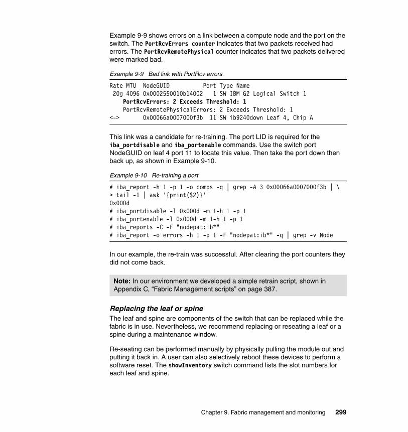
Example 9-9 shows errors on a link between a compute node and the port on the switch. The PortRcvErrors counter indicates that two packets received had errors. The PortRcvRemotePhysical counter indicates that two packets delivered were marked bad.
Example 9-9 Bad link with PortRcv errors
Rate MTU NodeGUID Port Type Name 20g 4096 0x0002550010b14002 1 SW IBM G2 Logical Switch 1 PortRcvErrors: 2 Exceeds Threshold: 1 PortRcvRemotePhysicalErrors: 2 Exceeds Threshold: 1<-> 0x00066a0007000f3b 11 SW ib9240down Leaf 4, Chip A
This link was a candidate for re-training. The port LID is required for the iba_portdisable and iba_portenable commands. Use the switch port NodeGUID on leaf 4 port 11 to locate this value. Then take the port down then back up, as shown in Example 9-10.
Example 9-10 Re-training a port
# iba_report -h 1 -p 1 -o comps -q | grep -A 3 0x00066a0007000f3b | \ > tail -1 | awk '{print($2)}'0x000d# iba_portdisable -l 0x000d -m 1-h 1 -p 1# iba_portenable -l 0x000d -m 1-h 1 -p 1# iba_reports -C -F "nodepat:ib*"# iba_report -o errors -h 1 -p 1 -F "nodepat:ib*" -q | grep -v Node
In our example, the re-train was successful. After clearing the port counters they did not come back.
Replacing the leaf or spineThe leaf and spine are components of the switch that can be replaced while the fabric is in use. Nevertheless, we recommend replacing or reseating a leaf or a spine during a maintenance window.
Re-seating can be performed manually by physically pulling the module out and putting it back in. A user can also selectively reboot these devices to perform a software reset. The showInventory switch command lists the slot numbers for each leaf and spine.
Note: In our environment we developed a simple retrain script, shown in Appendix C, “Fabric Management scripts” on page 387.
Chapter 9. Fabric management and monitoring 299

An IBM 7874-240 switch has the following layout:
� Leaves are slots 1–12 (lower hemisphere) and 13–24 (upper hemisphere).� Spines are 101–103 (lower hemisphere) and 104–106 (upper hemisphere).
A reboot of a leaf or non-master spine removes power from the card, and thus it is similar to a reseat. Because the removal of power from the card is controlled by the master spine, a master spine cannot remove power from itself. Therefore, to remove the power from a master spine, you must reboot it twice. The first reboot will cause the master function to fail over to the standby spine. The second reboot will allow the new master spine to remove power from the older master spine.
Example 9-11 shows errors on both sides of a link from a compute node to the port on the switch. The SymbolErrors indicate quality issues on the link. These can occur both when a link is idle and when there is traffic. The LinkErrorReovery indicates that the system completed two link retrains.
Example 9-11 Bad link with symbol errors
Rate MTU NodeGUID Port Type Name20g 4096 0x0002550010b1e820 1 SW IBM G2 Logical Switch 1
SymbolErrorCounter: 2 Exceeds Threshold: 1 LinkErrorRecoveryCounter: 2 Exceeds Threshold: 1<-> 0x00066a0007000f63 1 SW ib9240down Leaf 1, Chip A SymbolErrorCounter: 72 Exceeds Threshold: 1 1 LinkErrorRecoveryCounter: 2 Exceeds Threshold: 1174 of 226 Links Checked, 1 Errors found
When over time, if the SymbolErrors counters increase, and after a link re-train, the port counters continue to rise, even though this indicates that the errors are coming from the compute node, the leaf should be rebooted before moving on to a cable replacement. To reboot a leaf, use the following command:
# cmdall -H ib9240down ‘reboot now slot 3’
In our case, after the rebooting the leaf and clearing the port counters, SymbolErrorCounter increased again. Thus, we replaced the copper cable, and the port counters did not come back.
Power cycle or reboot the switchIf the errors are significant and extend across multiple connections, consider rebooting the switch or powering it off and on. You must power cycle the switch
Note: Software power removal of a spine is not possible on the IBM 7874-040 switch because it only has one spine with no backup.
300 HPC Clusters Using InfiniBand on IBM Power Systems Servers

by unplugging the cables. Wait five minutes before restoring power. Some installations have the switches connected to breakers and these can be shut off to simulate the same event. Afterward ensure that all lights and indicators are functioning properly before continuing. A reboot can also be done via the cmdall command or by telneting to a switch and using the CLI.
Example 9-12 shows a link with errors between a leaf and a spine. The PortRcvErrors indicates that the spine is receiving packets with errors.
Example 9-12 Spine to leaf error (spine 1)
Rate MTU NodeGUID Port Type Name 20g 4096 0x00066a0006000568 9 SW ib9240down8 Spine 1, Chip A PortRcvErrors: 2303 Exceeds Threshold: 7<-> 0x00066a0007000baf 19 SW ib9240down8 Leaf 1, Chip A
The switch command showInventory was used to look up the slot number and reboot the spine. As the slot reboots, it temporarily disappears from the output, until it becomes available again. Use the commands shown in Example 9-13.
Example 9-13 Rebooting the spine and re-checking for errors
# cmdall -H <switch> ‘showInventory’# cmdall -H <switch> ‘reboot now slot 101’# iba_reports -C -F "nodepat:ib*"# iba_report -o errors -h 1 -p 1 -F "nodepat:ib*" -q | grep -v Node
In our case, the errors came back, so we rebooted the entire switch using the following command:
# cmdall -H <switch> ‘reboot now all’
If errors persist even after clearing the counters, the suspect spine can be physically swapped with a spine in the other hemisphere. If the error moves to the new location (as seen in Example 9-14), consider replacing the spine.
Example 9-14 Spine to leaf error (spine 6)
Rate MTU NodeGUID Port Type Name20g 2048 0x00066a0006000571 7 SW ib9240down6 Spine 6, Chip A PortXmitDiscards: 12 Exceeds Threshold: 10<-> 0x00066a0007000baf 24 SW ib9240down6 Leaf 1, Chip A
In our case, we performed a firmware update and at the subsequent reboot the error never returned.
Chapter 9. Fabric management and monitoring 301
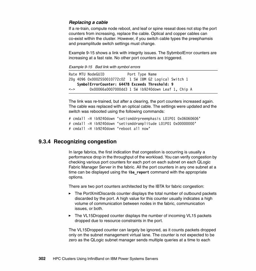
Replacing a cableIf a re-train, compute node reboot, and leaf or spine reseat does not stop the port counters from increasing, replace the cable. Optical and copper cables can co-exist within the cluster. However, if you switch cable types the preephamsis and preamplitude switch settings must change.
Example 9-15 shows a link with integrity issues. The SybmbolError counters are increasing at a fast rate. No other port counters are triggered.
Example 9-15 Bad link with symbol errors
Rate MTU NodeGUID Port Type Name20g 4096 0x0002550010772c02 1 SW IBM G2 Logical Switch 1 SymbolErrorCounter: 64478 Exceeds Threshold: 9<-> 0x00066a0007000dd3 1 SW ib9240down Leaf 1, Chip A
The link was re-trained, but after a clearing, the port counters increased again. The cable was replaced with an optical cable. The settings were updated and the switch was rebooted using the following commands:
# cmdall -H ib9240down ‘setismddrpreemphasis L01P01 0x06060606’# cmdall -H ib9240down ‘setismddramplitude L01P01 0x00000000’# cmdall -H ib9240down ‘reboot all now’
9.3.4 Recognizing congestion
In large fabrics, the first indication that congestion is occurring is usually a performance drop in the throughput of the workload. You can verify congestion by checking various port counters for each port on each subnet on each QLogic Fabric Manager Server in the fabric. All the port counters in any one subnet at a time can be displayed using the iba_report command with the appropriate options.
There are two port counters architected by the IBTA for fabric congestion:
� The PortXmitDiscards counter displays the total number of outbound packets discarded by the port. A high value for this counter usually indicates a high volume of communication between nodes in the fabric, communication issues, or both.
� The VL15Dropped counter displays the number of incoming VL15 packets dropped due to resource constraints in the port.
The VL15Dropped counter can largely be ignored, as it counts packets dropped only on the subnet management virtual lane. The counter is not expected to be zero as the QLogic subnet manager sends multiple queries at a time to each
302 HPC Clusters Using InfiniBand on IBM Power Systems Servers

device (especially switches), may drop a few which are counted, and then re-sends the packets. This results in no impact on fabric performance and only a minor performance drop for the subnet manager. Major subnet manager communication issues within the fabric will be reflected in the subnet manager log message entries in the /var/log messages file on the Linux server running the QLogic Fabric Manger.
In large fabrics, the first indication of congestion is usually a performance drop in workload throughput. Congestion can occur under the following conditions:
� Heavy load on the fabric due to user workload
� Problems with internal switch connections
� Devices in the fabric that are not running or are failing
� Links running below their enabled speed, misconfigured ports, or links with mistmatched speeds
Example 9-16 shows how to look for congestion using the port counters. Here the SymbolError and LinkErrorRecovery counters appeared after cluster maintenance.
Example 9-16 Symbol and link errors after maintenance
Rate MTU NodeGUID Port Type Name 20g 4096 0x0002550010b35020 1 SW IBM G2 Logical Switch 1 SymbolErrorCounter: 876 Exceeds Threshold: 3 LinkErrorRecoveryCounter: 13 Exceeds Threshold: 1<-> 0x00066a0007000f51 1 SW ib9240down Leaf 3, Chip A SymbolErrorCounter: 13 Exceeds Threshold: 3 LinkErrorRecoveryCounter: 13 Exceeds Threshold: 1174 of 226 Links Checked, 1 Errors found
After several hours of environment idling, the errors increased significantly (Example 9-17).
Example 9-17 Symbol and link errors increase on idle link
Rate MTU NodeGUID Port Type Name 20g 4096 0x0002550010b35020 1 SW IBM G2 Logical Switch 1 SymbolErrorCounter: 7317 Exceeds Threshold: 3 LinkErrorRecoveryCounter: 89 Exceeds Threshold: 1<-> 0x00066a0007000f51 1 SW ib9240down Leaf 3, Chip A SymbolErrorCounter: 83 Exceeds Threshold: 3 LinkErrorRecoveryCounter: 89 Exceeds Threshold: 1174 of 226 Links Checked, 1 Errors found
Chapter 9. Fabric management and monitoring 303
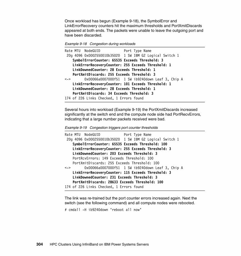
Once workload has begun (Example 9-18), the SymbolError and LinkErrorRecovery counters hit the maximum thresholds and PortXmitDiscards appeared at both ends. The packets were unable to leave the outgoing port and have been discarded.
Example 9-18 Congestion during workloads
Rate MTU NodeGUID Port Type Name 20g 4096 0x0002550010b35020 1 SW IBM G2 Logical Switch 1 SymbolErrorCounter: 65535 Exceeds Threshold: 3 LinkErrorRecoveryCounter: 255 Exceeds Threshold: 1 LinkDownedCounter: 28 Exceeds Threshold: 1 PortXmitDiscards: 255 Exceeds Threshold: 3<-> 0x00066a0007000f51 1 SW ib9240down Leaf 3, Chip A LinkErrorRecoveryCounter: 101 Exceeds Threshold: 1 LinkDownedCounter: 28 Exceeds Threshold: 1 PortXmitDiscards: 34 Exceeds Threshold: 3174 of 226 Links Checked, 1 Errors found
Several hours into workload (Example 9-19) the PortXmitDiscards increased significantly at the switch end and the compute node side had PortRecvErrors, indicating that a large number packets received were bad.
Example 9-19 Congestion triggers port counter thresholds
Rate MTU NodeGUID Port Type Name 20g 4096 0x0002550010b35020 1 SW IBM G2 Logical Switch 1 SymbolErrorCounter: 65535 Exceeds Threshold: 100 LinkErrorRecoveryCounter: 255 Exceeds Threshold: 3 LinkDownedCounter: 203 Exceeds Threshold: 3 PortRcvErrors: 149 Exceeds Threshold: 100 PortXmitDiscards: 255 Exceeds Threshold: 100<-> 0x00066a0007000f51 1 SW ib9240down Leaf 3, Chip A LinkErrorRecoveryCounter: 115 Exceeds Threshold: 3 LinkDownedCounter: 231 Exceeds Threshold: 3 PortXmitDiscards: 28633 Exceeds Threshold: 100174 of 226 Links Checked, 1 Errors found
The link was re-trained but the port counter errors increased again. Next the switch (see the following command) and all compute nodes were rebooted.
# cmdall -H ib9240down ‘reboot all now’
304 HPC Clusters Using InfiniBand on IBM Power Systems Servers
9.3.5 Identifying sources of congestion
Applications with a high level of communication between nodes, such as an all to all type benchmark, can cause congestion in the best constructed fabrics for a period of time. Check the level of communication in the applications in the fabric to determine whether this is the cause of the congestion.
Fabrics for IBM Power Systems are usually designed to provide maximum bandwidth. Full bisectional bandwidth (FBB) simply means that there are the same number of links between switches (including internal connections on a backplane) as there are number of nodes in the fabric. Clusters can be designed in an oversubscribed CBB configuration. An oversubscribed constant bisectional bandwidth (CBB) means that there are more nodes than interswitch (ISL) links, so each link carries more traffic. In such a configuration, congestion will occur more readily when running high communication applications.
This type of situation can also occur when there are problems with the internal switch connections within a chassis. Various error counters in addition to PortXmitDiscards will have increased values. Check the error counters using the iba_report command with appropriate options.
Congestion can also be caused when devices in the fabric are not running properly or are failing. The most common instances are cable or other hardware problems.
Using the iba_report command, you can also identify links that are running below their enabled speed (slow links), links that are not configured properly, and links that have mismatched speeds.
Typically, you will use the slowconnlinks output type for iba_report, as this includes the output types slowconfiglinks and slowlinks. Other output types such as misconnlinks and misconfiglinks mirror the output of slowconnlinks and slowconfiglinks.
This output allows you to find DDR links (4x) running at SDR (1x) speeds, links configured to run at SDR (1x) rather than DDR (4x or 12x) speeds, or DDR devices connected to SDR devices. The DDR devices connected to SDR devices do not represent a problem if they were intentionally cabled that way.
Chapter 9. Fabric management and monitoring 305

In Example 9-20, the port shows 1x Active Link, which is not equal to the 4x Enabled Link width.
Example 9-20 SDR active rate not equal to enabled DDR rate
Links running slower than expected:Rate NodeGUID Port Type Name Active Enabled2.5g 0x00066a0005000481 7 SW My9240 1x 2.5Gb 1-4x 2.5Gb<-> 0x00066a009800447b 2 CA MyNode1 1x 2.5Gb 1-4x 2.5Gb
In Example 9-21 the port shows SDR active (2.5 Gbps) speed, which is not equal to the enabled DDR speed (5.0 Gbps).
Example 9-21 SDR active speed not equal to enabled DDR speed
Links running slower than expected:Rate NodeGUID Port Type Name Active Enabled10g 0x00066a0098007db4 1 CA MyNode2 4x 2.5Gb 1-4x 2.5-5Gb<-> 0x00066a00d9000275 13 SW My9240 4x 2.5Gb 1-4x 2.5-5Gb
In Example 9-22, a DDR-capable link is configured to run at the SDR rate. The port on MyNode3 is configured to run at SDR (1x) rather than DDR (4x). Use the switch CLI command ismPortSetSpeed to verify or change the rate, or both.
Example 9-22 DDR capable link configured to run at SDR rate
Links configured to run slower than supported:Rate NodeGUID Port Type Name Enabled Supported2.5g 0x00066a0005000481 3 SW My9240 1-4x 2.5Gb 1-4x 2.5Gb<-> 0x00066a009800413e 2 CA MyNode3 1x 2.5Gb 1-4x 2.5Gb
In Example 9-23, a DDR host channel adapter (HCA) is connected to an SDR switch port.
Example 9-23 DDR host channel adapter connected to an SDR switch port
Links connected with mismatched speed potential:Rate NodeGUID Port Type Name Supported10g 0x00066a009800706a 2 CA MyNode4 1-4x 2.5-5Gb<-> 0x00066a00d8000229 8 SW My9240 1-4x 2.5Gb
306 HPC Clusters Using InfiniBand on IBM Power Systems Servers
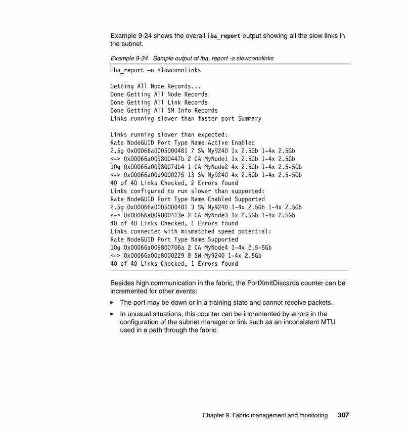
Example 9-24 shows the overall iba_report output showing all the slow links in the subnet.
Example 9-24 Sample output of iba_report -o slowconnlinks
Iba_report –o slowconnlinks
Getting All Node Records...Done Getting All Node RecordsDone Getting All Link RecordsDone Getting All SM Info RecordsLinks running slower than faster port Summary
Links running slower than expected:Rate NodeGUID Port Type Name Active Enabled2.5g 0x00066a0005000481 7 SW My9240 1x 2.5Gb 1-4x 2.5Gb<-> 0x00066a009800447b 2 CA MyNode1 1x 2.5Gb 1-4x 2.5Gb10g 0x00066a0098007db4 1 CA MyNode2 4x 2.5Gb 1-4x 2.5-5Gb<-> 0x00066a00d9000275 13 SW My9240 4x 2.5Gb 1-4x 2.5-5Gb40 of 40 Links Checked, 2 Errors foundLinks configured to run slower than supported:Rate NodeGUID Port Type Name Enabled Supported2.5g 0x00066a0005000481 3 SW My9240 1-4x 2.5Gb 1-4x 2.5Gb<-> 0x00066a009800413e 2 CA MyNode3 1x 2.5Gb 1-4x 2.5Gb40 of 40 Links Checked, 1 Errors foundLinks connected with mismatched speed potential:Rate NodeGUID Port Type Name Supported10g 0x00066a009800706a 2 CA MyNode4 1-4x 2.5-5Gb<-> 0x00066a00d8000229 8 SW My9240 1-4x 2.5Gb40 of 40 Links Checked, 1 Errors found
Besides high communication in the fabric, the PortXmitDiscards counter can be incremented for other events:
� The port may be down or in a training state and cannot receive packets.
� In unusual situations, this counter can be incremented by errors in the configuration of the subnet manager or link such as an inconsistent MTU used in a path through the fabric.
Chapter 9. Fabric management and monitoring 307
� A packet has been queued in the switch for a length of time that exceeds one of two attributes:
– The switch lifetime limit – The switch HOQ lifetime limit (HOQ stands for head of queue.)
Once the time limit is reached, the packet is discarded and the counter incremented. Default settings are shipped in the QLogic subnet manager configuration file and can be adjusted with caution.
� The port will be incremented as well when packets are discarded due to a link failure, a non-responsive channel adapter, or a server that is not accepting packets even though the link appears active.
Once the sources of the congestion are located, steps can be taken to alleviate congestion, such as correcting fabric configuration and replacing cables or other hardware.
If you still consider the congestion to be excessive after having thoroughly checked and taken corresponding recommended actions to fix any hardware or configuration issues, then gather support information by obtaining capture reports for the switches and the QLogic subnet manger. Among other information gathered, these captures will include the linear forwarding tables configured in the switches by the QLogic subnet manager that are used to route traffic through the fabric.
9.3.6 Tracing a route
Tracing a route can be helpful in pinpointing congestion issues to a particular cable port or ISL port on a switch. The attributes of that port can then be tweaked using the port configuration commands in the switch CLI.
You can trace a specific route through a fabric with various iba_report options. You will need to be familiar with how your fabric is cabled and substitute the proper information.
This example is based on:
� One node connected to a leaf port in the lower hemisphere of an IBM 7874-240 IB switch.
� One node connected to a leaf port in the upper hemisphere of the same switch.
Note: You may need to run the capture commands from more than one host based QLogic Fabric Manager.
308 HPC Clusters Using InfiniBand on IBM Power Systems Servers

� Each node has two ports.
� LMC is configured as two, resulting in four LIDs per IBM Logical HCA. This means that there will be 16 paths that a packet can take from one IBM Logical HCA on one node to the other IBM Logical HCA on another node.
In this example, one route will be traced. In a real-life situation you may want to trace multiple routes if trying to narrow issues to a single switch port.
Step one is to find the node GUID of the IBM Logical HCAs on the node. We will trace a route from IBM Logical HCA node guid: 0x000255004052b401 to IBM Logical HCA node guid: 0x000255004084fa01.
Once you have the node GUIDs for the IBM Logical HCAs on the pair of nodes, run iba_report with the route output type option supplying the parameters for the source nodeguid, -S, and the destination nodeguid, -D arguments. See Example 9-25.
Example 9-25 Running iba_report to trace a route
iba_report -o route -S nodeguid:0x000255004052b401 -D \ > nodeguid:0x000255004084fa01
In the top part of the output, you can verify the nodeguids that you used for tracing the route and the number of paths available, in this case 16, between the nodeguids. See Example 9-26.
Example 9-26 Summary information from iba_report to trace a route
Getting All Node Records...Done Getting All Node RecordsDone Getting All Link RecordsDone Getting All SM Info RecordsRoutes Summary Between: Node: 0x000255004052b401 CA IBM G2 Logical HCAand Node: 0x000255004084fa01 CA IBM G2 Logical HCA
Routes between ports: 0x000255004052b401 2 CA IBM G2 Logical HCAand 0x000255004084fa01 2 CA IBM G2 Logical HCA16 Paths
Each path shows the entire route through the fabric starting with a source global ID (SGID) and a source LID (SLID) and ends with a destination global ID (DGID) and destination LID (DLID).
Chapter 9. Fabric management and monitoring 309

The route path is shown in Example 9-27. The first path displayed between the HCAs can be read like this:
� The path starts with our source HCA on port 2 and goes to port 3 of the logical switch (internal to the node) with nodeguid: 0x000255004052b421.
� The path continues out port 1 (cable port on the node) of the logical switch with nodeguid: 0x000255004052b421 to port 1 (cable port on the switch) on the SilverStorm 9240 switch leaf 10 with nodeguid: 0x00066a00070023f9. This leaf is located in the lower hemisphere of the switch, but you will notice (other than our naming sequence) that this information is not available from this output.
� The path continues out port 21 (internal switch link) on leaf 10 of IBM 7874-2409240 switch to port 15 (internal switch link) on spine 4 switch chip B with nodeguid: 0x00066a1006000ccf.
� The path continues out port 1 of spine 4 switch chip B to port 17 on leaf 13 with nodeguid: 0x00066a00070022eb. This leaf is located in the upper hemisphere. Again, you will notice (other than our naming sequence) that this information is not available from this output. Since all leafs in both hemispheres communicate through the backplane, this leaf could easily be located in the lower hemisphere.
� The path continues out port 4 of leaf 13 (cable port) of the switch to port 1 (cable port) to the IBM Logical Switch with nodeguid:0x000255004084fa21.
� The path continues out port 3 (internal to the node) of the IBM Logical Switch and ends at our destination HCA port 2.
Example 9-27 First path displayed between the HCAs
SGID: 0xfe8000000000000a:000255004052b411 DGID: 0xfe8000000000000a:000255004084fa11 SLID: 0x0034 DLID: 0x0040 Reversible: Y PKey: 0xffff
Note: The SGID and the DGID will be the same for each path, as this refers to the IBM Logical HCAs. The SLID and the DLID will be different, as those refer to the starting LID and ending LID for each path.
Note: Spine 4 is in the upper hemisphere IBM 7874-240. The spine slots start in the lower hemisphere (1, 2, 3) and continue in the upper hemisphere (4, 5, 6). All the leafs and spines in both hemispheres are connected to the backplane and can communicate with each other. The port where the path originally entered the switch on leaf 10 was in the lower hemisphere.
310 HPC Clusters Using InfiniBand on IBM Power Systems Servers
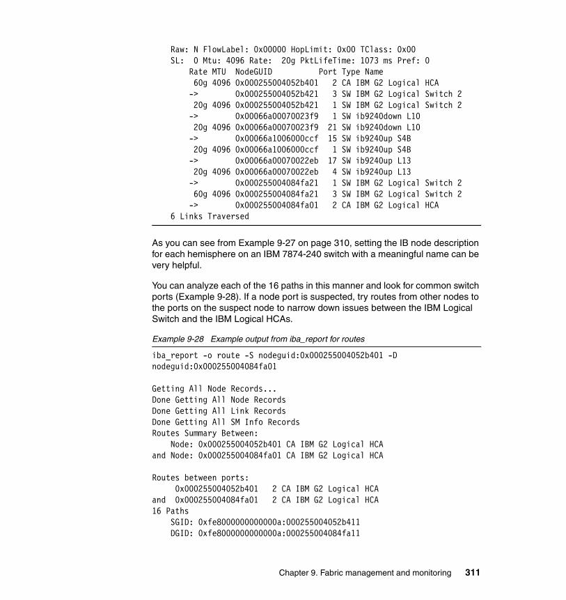
Raw: N FlowLabel: 0x00000 HopLimit: 0x00 TClass: 0x00 SL: 0 Mtu: 4096 Rate: 20g PktLifeTime: 1073 ms Pref: 0 Rate MTU NodeGUID Port Type Name 60g 4096 0x000255004052b401 2 CA IBM G2 Logical HCA -> 0x000255004052b421 3 SW IBM G2 Logical Switch 2 20g 4096 0x000255004052b421 1 SW IBM G2 Logical Switch 2 -> 0x00066a00070023f9 1 SW ib9240down L10 20g 4096 0x00066a00070023f9 21 SW ib9240down L10 -> 0x00066a1006000ccf 15 SW ib9240up S4B 20g 4096 0x00066a1006000ccf 1 SW ib9240up S4B -> 0x00066a00070022eb 17 SW ib9240up L13 20g 4096 0x00066a00070022eb 4 SW ib9240up L13 -> 0x000255004084fa21 1 SW IBM G2 Logical Switch 2 60g 4096 0x000255004084fa21 3 SW IBM G2 Logical Switch 2 -> 0x000255004084fa01 2 CA IBM G2 Logical HCA 6 Links Traversed
As you can see from Example 9-27 on page 310, setting the IB node description for each hemisphere on an IBM 7874-240 switch with a meaningful name can be very helpful.
You can analyze each of the 16 paths in this manner and look for common switch ports (Example 9-28). If a node port is suspected, try routes from other nodes to the ports on the suspect node to narrow down issues between the IBM Logical Switch and the IBM Logical HCAs.
Example 9-28 Example output from iba_report for routes
iba_report -o route -S nodeguid:0x000255004052b401 -D nodeguid:0x000255004084fa01
Getting All Node Records...Done Getting All Node RecordsDone Getting All Link RecordsDone Getting All SM Info RecordsRoutes Summary Between: Node: 0x000255004052b401 CA IBM G2 Logical HCAand Node: 0x000255004084fa01 CA IBM G2 Logical HCA
Routes between ports: 0x000255004052b401 2 CA IBM G2 Logical HCAand 0x000255004084fa01 2 CA IBM G2 Logical HCA16 Paths SGID: 0xfe8000000000000a:000255004052b411 DGID: 0xfe8000000000000a:000255004084fa11
Chapter 9. Fabric management and monitoring 311
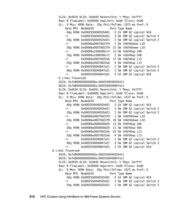
SLID: 0x0034 DLID: 0x0040 Reversible: Y PKey: 0xffff Raw: N FlowLabel: 0x00000 HopLimit: 0x00 TClass: 0x00 SL: 0 Mtu: 4096 Rate: 20g PktLifeTime: 1073 ms Pref: 0 Rate MTU NodeGUID Port Type Name 60g 4096 0x000255004052b401 2 CA IBM G2 Logical HCA -> 0x000255004052b421 3 SW IBM G2 Logical Switch 2 20g 4096 0x000255004052b421 1 SW IBM G2 Logical Switch 2 -> 0x00066a00070023f9 1 SW ib9240down L10 20g 4096 0x00066a00070023f9 21 SW ib9240down L10 -> 0x00066a1006000ccf 15 SW ib9240up S4B 20g 4096 0x00066a1006000ccf 1 SW ib9240up S4B -> 0x00066a00070022eb 17 SW ib9240up L13 20g 4096 0x00066a00070022eb 4 SW ib9240up L13 -> 0x000255004084fa21 1 SW IBM G2 Logical Switch 2 60g 4096 0x000255004084fa21 3 SW IBM G2 Logical Switch 2 -> 0x000255004084fa01 2 CA IBM G2 Logical HCA 6 Links Traversed SGID: 0xfe8000000000000a:000255004052b411 DGID: 0xfe8000000000000a:000255004084fa11 SLID: 0x0034 DLID: 0x0041 Reversible: Y PKey: 0xffff Raw: N FlowLabel: 0x00000 HopLimit: 0x00 TClass: 0x00 SL: 0 Mtu: 4096 Rate: 20g PktLifeTime: 1073 ms Pref: 0 Rate MTU NodeGUID Port Type Name 60g 4096 0x000255004052b401 2 CA IBM G2 Logical HCA -> 0x000255004052b421 3 SW IBM G2 Logical Switch 2 20g 4096 0x000255004052b421 1 SW IBM G2 Logical Switch 2 -> 0x00066a00070023f9 1 SW ib9240down L10 20g 4096 0x00066a00070023f9 18 SW ib9240down L10 -> 0x00066a0006000d25 13 SW ib9240up S6A 20g 4096 0x00066a0006000d25 11 SW ib9240up S6A -> 0x00066a00070022eb 23 SW ib9240up L13 20g 4096 0x00066a00070022eb 4 SW ib9240up L13 -> 0x000255004084fa21 1 SW IBM G2 Logical Switch 2 60g 4096 0x000255004084fa21 3 SW IBM G2 Logical Switch 2 -> 0x000255004084fa01 2 CA IBM G2 Logical HCA6 Links Traversed SGID: 0xfe8000000000000a:000255004052b411 DGID: 0xfe8000000000000a:000255004084fa11 SLID: 0x0034 DLID: 0x0042 Reversible: Y PKey: 0xffff Raw: N FlowLabel: 0x00000 HopLimit: 0x00 TClass: 0x00 SL: 0 Mtu: 4096 Rate: 20g PktLifeTime: 1073 ms Pref: 0 Rate MTU NodeGUID Port Type Name 60g 4096 0x000255004052b401 2 CA IBM G2 Logical HCA -> 0x000255004052b421 3 SW IBM G2 Logical Switch 2 20g 4096 0x000255004052b421 1 SW IBM G2 Logical Switch 2
312 HPC Clusters Using InfiniBand on IBM Power Systems Servers
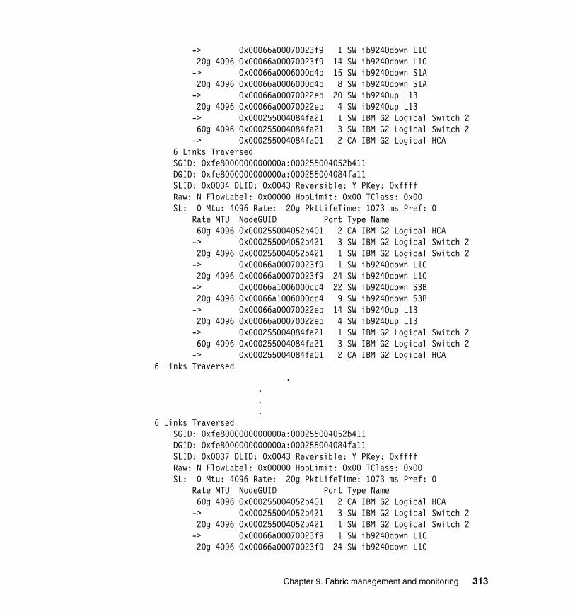
-> 0x00066a00070023f9 1 SW ib9240down L10 20g 4096 0x00066a00070023f9 14 SW ib9240down L10 -> 0x00066a0006000d4b 15 SW ib9240down S1A 20g 4096 0x00066a0006000d4b 8 SW ib9240down S1A -> 0x00066a00070022eb 20 SW ib9240up L13 20g 4096 0x00066a00070022eb 4 SW ib9240up L13 -> 0x000255004084fa21 1 SW IBM G2 Logical Switch 2 60g 4096 0x000255004084fa21 3 SW IBM G2 Logical Switch 2 -> 0x000255004084fa01 2 CA IBM G2 Logical HCA 6 Links Traversed SGID: 0xfe8000000000000a:000255004052b411 DGID: 0xfe8000000000000a:000255004084fa11 SLID: 0x0034 DLID: 0x0043 Reversible: Y PKey: 0xffff Raw: N FlowLabel: 0x00000 HopLimit: 0x00 TClass: 0x00 SL: 0 Mtu: 4096 Rate: 20g PktLifeTime: 1073 ms Pref: 0 Rate MTU NodeGUID Port Type Name 60g 4096 0x000255004052b401 2 CA IBM G2 Logical HCA -> 0x000255004052b421 3 SW IBM G2 Logical Switch 2 20g 4096 0x000255004052b421 1 SW IBM G2 Logical Switch 2 -> 0x00066a00070023f9 1 SW ib9240down L10 20g 4096 0x00066a00070023f9 24 SW ib9240down L10 -> 0x00066a1006000cc4 22 SW ib9240down S3B 20g 4096 0x00066a1006000cc4 9 SW ib9240down S3B -> 0x00066a00070022eb 14 SW ib9240up L13 20g 4096 0x00066a00070022eb 4 SW ib9240up L13 -> 0x000255004084fa21 1 SW IBM G2 Logical Switch 2 60g 4096 0x000255004084fa21 3 SW IBM G2 Logical Switch 2 -> 0x000255004084fa01 2 CA IBM G2 Logical HCA6 Links Traversed . . . .6 Links Traversed SGID: 0xfe8000000000000a:000255004052b411 DGID: 0xfe8000000000000a:000255004084fa11 SLID: 0x0037 DLID: 0x0043 Reversible: Y PKey: 0xffff Raw: N FlowLabel: 0x00000 HopLimit: 0x00 TClass: 0x00 SL: 0 Mtu: 4096 Rate: 20g PktLifeTime: 1073 ms Pref: 0 Rate MTU NodeGUID Port Type Name 60g 4096 0x000255004052b401 2 CA IBM G2 Logical HCA -> 0x000255004052b421 3 SW IBM G2 Logical Switch 2 20g 4096 0x000255004052b421 1 SW IBM G2 Logical Switch 2 -> 0x00066a00070023f9 1 SW ib9240down L10 20g 4096 0x00066a00070023f9 24 SW ib9240down L10
Chapter 9. Fabric management and monitoring 313
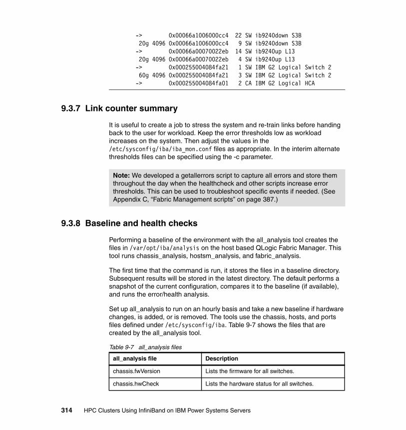
-> 0x00066a1006000cc4 22 SW ib9240down S3B 20g 4096 0x00066a1006000cc4 9 SW ib9240down S3B -> 0x00066a00070022eb 14 SW ib9240up L13 20g 4096 0x00066a00070022eb 4 SW ib9240up L13 -> 0x000255004084fa21 1 SW IBM G2 Logical Switch 2 60g 4096 0x000255004084fa21 3 SW IBM G2 Logical Switch 2 -> 0x000255004084fa01 2 CA IBM G2 Logical HCA
9.3.7 Link counter summary
It is useful to create a job to stress the system and re-train links before handing back to the user for workload. Keep the error thresholds low as workload increases on the system. Then adjust the values in the /etc/sysconfig/iba/iba_mon.conf files as appropriate. In the interim alternate thresholds files can be specified using the -c parameter.
9.3.8 Baseline and health checks
Performing a baseline of the environment with the all_analysis tool creates the files in /var/opt/iba/analysis on the host based QLogic Fabric Manager. This tool runs chassis_analysis, hostsm_analysis, and fabric_analysis.
The first time that the command is run, it stores the files in a baseline directory. Subsequent results will be stored in the latest directory. The default performs a snapshot of the current configuration, compares it to the baseline (if available), and runs the error/health analysis.
Set up all_analysis to run on an hourly basis and take a new baseline if hardware changes, is added, or is removed. The tools use the chassis, hosts, and ports files defined under /etc/sysconfig/iba. Table 9-7 shows the files that are created by the all_analysis tool.
Table 9-7 all_analysis files
Note: We developed a getallerrors script to capture all errors and store them throughout the day when the healthcheck and other scripts increase error thresholds. This can be used to troubleshoot specific events if needed. (See Appendix C, “Fabric Management scripts” on page 387.)
all_analysis file Description
chassis.fwVersion Lists the firmware for all switches.
chassis.hwCheck Lists the hardware status for all switches.
314 HPC Clusters Using InfiniBand on IBM Power Systems Servers
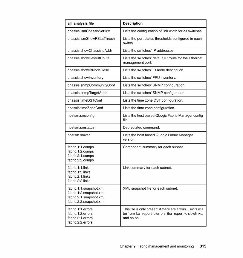
chassis.ismChassisSet12x Lists the configuration of link width for all switches.
chassis.ismShowPStatThresh Lists the port status thresholds configured in each switch.
chassis.showChassisIpAddr Lists the switches’ IP addresses.
chassis.showDefaultRoute Lists the switches’ default IP route for the Ethernet management port.
chassis.showIBNodeDesc Lists the switches’ IB node description.
chassis.showInventory Lists the switches’ FRU inventory.
chassis.snmpCommunityConf Lists the switches’ SNMP configuration.
chassis.snmpTargetAddr Lists the switches’ SNMP configuration.
chassis.timeDSTConf Lists the time zone DST configuration.
chassis.timeZoneConf Lists the time zone configuration.
hostsm.smconfig Lists the host based QLogic Fabric Manager config file.
hostsm.smstatus Depreciated command.
hostsm.smver Lists the host based QLogic Fabric Manager version.
fabric.1:1.compsfabric.1:2.compsfabric.2:1.compsfabric.2:2.comps
Component summary for each subnet.
fabric.1:1.linksfabric.1:2.linksfabric.2:1.linksfabric.2:2.links
Link summary for each subnet.
fabric.1:1.snapshot.xmlfabric.1:2.snapshot.xmlfabric.2:1.snapshot.xmlfabric.2:2.snapshot.xml
XML snapshot file for each subnet.
fabric.1:1.errorsfabric.1:2.errorsfabric.2:1.errorsfabric.2:2.errors
This file is only present if there are errors. Errors will be from iba_report -o errors, iba_report -o slowlinks, and so on.
all_analysis file Description
Chapter 9. Fabric management and monitoring 315
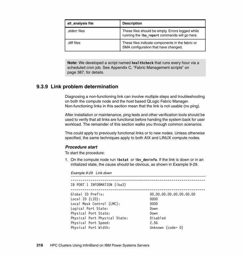
9.3.9 Link problem determination
Diagnosing a non-functioning link can involve multiple steps and troubleshooting on both the compute node and the host based QLogic Fabric Manager. Non-functioning links in this section mean that the link is not usable (no ping).
After installation or maintenance, ping tests and other verification tools should be used to verify that all links are functional before handing the system back for user workload. The remainder of this section walks you through common scenarios.
This could apply to previously functional links or to new nodes. Unless otherwise specified, the same techniques apply to both AIX and LINUX compute nodes.
Procedure startTo start the procedure:
1. On the compute node run ibstat or ibv_devinfo. If the link is down or in an initialized state, the cause should be obvious, as shown in Example 9-29.
Example 9-29 Link down
--------------------------------------------------------------------IB PORT 1 INFORMATION (iba3)--------------------------------------------------------------------Global ID Prefix: 00.00.00.00.00.00.00.00Local ID (LID): 0000Local Mask Control (LMC): 0000Logical Port State: DownPhysical Port State: DownPhysical Port Physical State: DisabledPhysical Port Speed: 2.5GPhysical Port Width: Unknown (code= 0)
.stderr files These files should be empty. Errors logged while running the iba_report commands will go here.
.diff files These files indicate components in the fabric or SMA configuration that have changed.
Note: We developed a script named healthcheck that runs every hour via a scheduled cron job. See Appendix C, “Fabric Management scripts” on page 387, for details.
all_analysis file Description
316 HPC Clusters Using InfiniBand on IBM Power Systems Servers

Maximum Transmission Unit Capacity: 2048Current Number of Partition Keys: 1Partition Key List: P_Key[0]: ffffCurrent Number of GUID's: 1Globally Unique ID List: GUID[0]: 00.02.55.00.60.06.7c.00
2. Check all connection lights. The switch end should have a solid blue light on the port. The node should have a green light above the port on the adapter.
– If there are no lights, check the cable. If you find it in one of the following conditions plug it in correctly. No additional configuration should be required.
• Is it the correct cable? Is it plugged into the correct switch, leaf and port?
• Do the labels match at both ends?
• Is it seated properly?
– If are lights on, check the device:
• AIX:
lsdev -C | grep Infini
• LINUX:
There is no direct equivalent so do both steps below.
If the device is in a defined state.
• Verify that the HCAs are set to “HMC Managed=Yes” in the compute node’s managed profile on the HMC.
• Verify that the /etc/hosts has a valid entry and ip address for those interfaces.
• Verify that the configuration has a valid netmask and ip addresses.
AIX:
lsattr -El ib0
LINUX:
cat /etc/sysconfig/network/ifcfg-ib0
• Verify that the on-board IB port (ehca4) is not configured (p575 heavy nodes only).
AIX:
ibstat -p (You should see up to iba3)
Chapter 9. Fabric management and monitoring 317
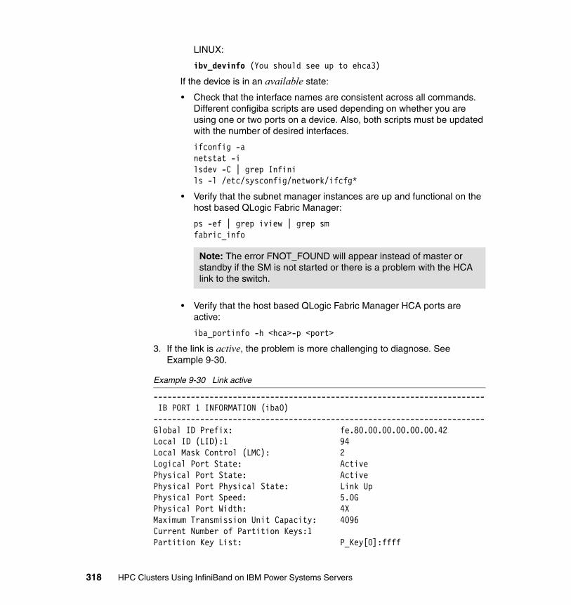
LINUX:
ibv_devinfo (You should see up to ehca3)
If the device is in an available state:
• Check that the interface names are consistent across all commands. Different configiba scripts are used depending on whether you are using one or two ports on a device. Also, both scripts must be updated with the number of desired interfaces.
ifconfig -anetstat -ilsdev -C | grep Infinils -l /etc/sysconfig/network/ifcfg*
• Verify that the subnet manager instances are up and functional on the host based QLogic Fabric Manager:
ps -ef | grep iview | grep smfabric_info
• Verify that the host based QLogic Fabric Manager HCA ports are active:
iba_portinfo -h <hca>-p <port>
3. If the link is active, the problem is more challenging to diagnose. See Example 9-30.
Example 9-30 Link active
----------------------------------------------------------------------- IB PORT 1 INFORMATION (iba0)-----------------------------------------------------------------------Global ID Prefix: fe.80.00.00.00.00.00.42Local ID (LID):1 94Local Mask Control (LMC): 2Logical Port State: ActivePhysical Port State: ActivePhysical Port Physical State: Link UpPhysical Port Speed: 5.0GPhysical Port Width: 4XMaximum Transmission Unit Capacity: 4096Current Number of Partition Keys:1Partition Key List: P_Key[0]:ffff
Note: The error FNOT_FOUND will appear instead of master or standby if the SM is not started or there is a problem with the HCA link to the switch.
318 HPC Clusters Using InfiniBand on IBM Power Systems Servers
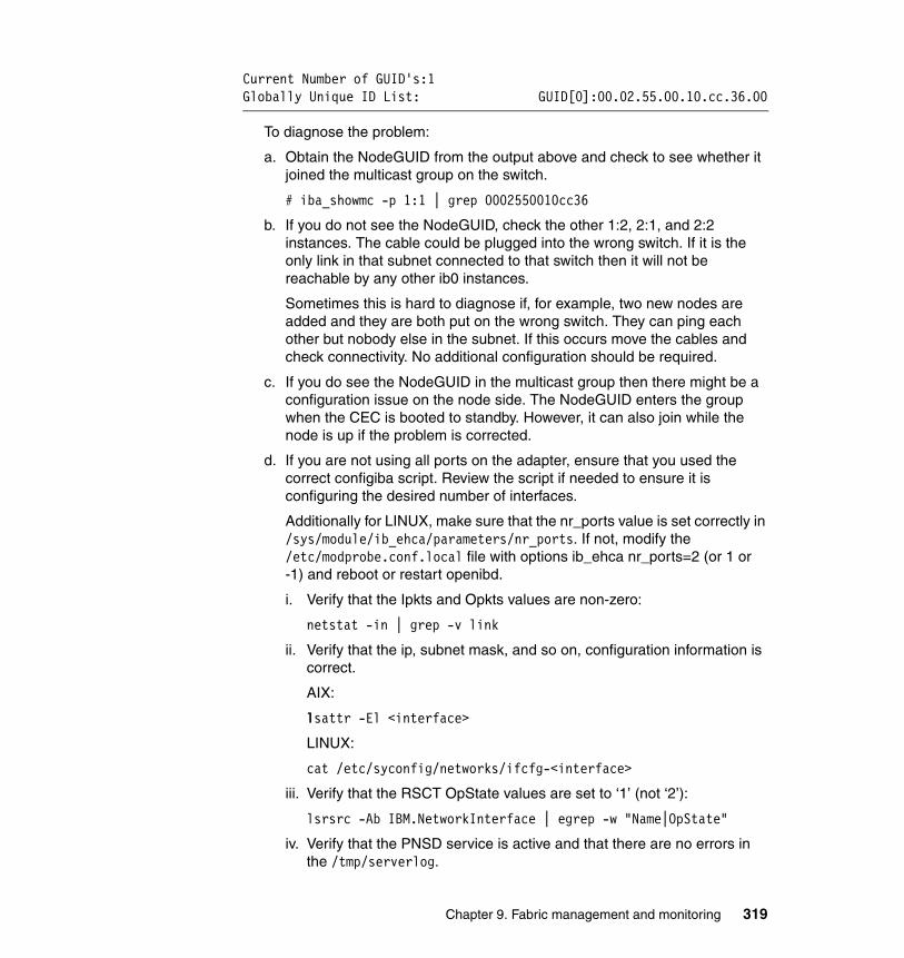
Current Number of GUID's:1Globally Unique ID List: GUID[0]:00.02.55.00.10.cc.36.00
To diagnose the problem:
a. Obtain the NodeGUID from the output above and check to see whether it joined the multicast group on the switch.
# iba_showmc -p 1:1 | grep 0002550010cc36
b. If you do not see the NodeGUID, check the other 1:2, 2:1, and 2:2 instances. The cable could be plugged into the wrong switch. If it is the only link in that subnet connected to that switch then it will not be reachable by any other ib0 instances.
Sometimes this is hard to diagnose if, for example, two new nodes are added and they are both put on the wrong switch. They can ping each other but nobody else in the subnet. If this occurs move the cables and check connectivity. No additional configuration should be required.
c. If you do see the NodeGUID in the multicast group then there might be a configuration issue on the node side. The NodeGUID enters the group when the CEC is booted to standby. However, it can also join while the node is up if the problem is corrected.
d. If you are not using all ports on the adapter, ensure that you used the correct configiba script. Review the script if needed to ensure it is configuring the desired number of interfaces.
Additionally for LINUX, make sure that the nr_ports value is set correctly in /sys/module/ib_ehca/parameters/nr_ports. If not, modify the /etc/modprobe.conf.local file with options ib_ehca nr_ports=2 (or 1 or -1) and reboot or restart openibd.
i. Verify that the Ipkts and Opkts values are non-zero:
netstat -in | grep -v link
ii. Verify that the ip, subnet mask, and so on, configuration information is correct.
AIX:
lsattr -El <interface>
LINUX:
cat /etc/syconfig/networks/ifcfg-<interface>
iii. Verify that the RSCT OpState values are set to ‘1’ (not ‘2’):
lsrsrc -Ab IBM.NetworkInterface | egrep -w "Name|OpState"
iv. Verify that the PNSD service is active and that there are no errors in the /tmp/serverlog.
Chapter 9. Fabric management and monitoring 319

v. Verify that the driver MTU for the IB interfaces is set to the same value configured in Chapter 6, “Configuring the InfiniBand fabric” on page 177, on the QLogic Fabric Manager and switches.
AIX:
ibstat -p | grep “Maximum Transmission Unit Capacity”
LINUX:
ibv_devinfo | grep mtu
vi. Verify that these additional MTU settings are correct and that super packets is turned on on the compute nodes.
AIX (only):
lsattr -El <ib interface>| egrep "mtu|superpacket|tcp"netstat -in | grep -v linkifconfig ib0
vii. Verify that the link has the correct 4096 MTU (not 2048). Check both hemispheres:
iba_report -o links -h <instance> -p <port> | grep <NodeGUID
Mixed MTU driver settings are not supported. Ensure that all switch ports and nodes are set to the same value. Each port on the switch has an MTU setting and it should be the same. Redirect output to a file and verify that they are set correctly (even unpopulated portions of a switch):
cmdall -C 'ismChassisSetMtu' > /tmp/ismChassisSetMtu.out
If any updates are made the switch must be rebooted for the changes to take effect. The only 2048 links that should remain are the ports for the QLogic Fabric Manager HCAs:
# iba_reports -o links -q | grep 204820g 2048 0x00066a0007000f51 6 SW ib9240down6 Leaf 3, Chip A20g 2048 0x00066a0007000f63 6 SW ib9240down6 Leaf 1, Chip
viii.During the setup procedure described in Chapter 6, “Configuring the InfiniBand fabric” on page 177, the ports were all set to the default configuration. Amplitude and pre-emphasis are used to adjust how the switch drives the signal to the cable. This ultimately affects the quality of the signal as it enters the receiving logic on the other side of the cable. Different cables and combinations of devices (switches and HCAs) exhibit different electrical characteristics and require different amplitude and pre-emphasis settings, as stated below.
320 HPC Clusters Using InfiniBand on IBM Power Systems Servers
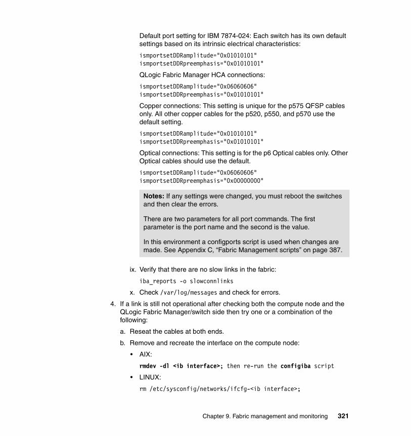
Default port setting for IBM 7874-024: Each switch has its own default settings based on its intrinsic electrical characteristics:
ismportsetDDRamplitude="0x01010101"ismportsetDDRpreemphasis="0x01010101"
QLogic Fabric Manager HCA connections:
ismportsetDDRamplitude="0x06060606"ismportsetDDRpreemphasis="0x01010101"
Copper connections: This setting is unique for the p575 QFSP cables only. All other copper cables for the p520, p550, and p570 use the default setting.
ismportsetDDRamplitude="0x01010101"ismportsetDDRpreemphasis="0x01010101"
Optical connections: This setting is for the p6 Optical cables only. Other Optical cables should use the default.
ismportsetDDRamplitude="0x06060606"ismportsetDDRpreemphasis="0x00000000"
ix. Verify that there are no slow links in the fabric:
iba_reports -o slowconnlinks
x. Check /var/log/messages and check for errors.
4. If a link is still not operational after checking both the compute node and the QLogic Fabric Manager/switch side then try one or a combination of the following:
a. Reseat the cables at both ends.
b. Remove and recreate the interface on the compute node:
• AIX:
rmdev -dl <ib interface>; then re-run the configiba script
• LINUX:
rm /etc/sysconfig/networks/ifcfg-<ib interface>;
Notes: If any settings were changed, you must reboot the switches and then clear the errors.
There are two parameters for all port commands. The first parameter is the port name and the second is the value.
In this environment a configports script is used when changes are made. See Appendix C, “Fabric Management scripts” on page 387.
Chapter 9. Fabric management and monitoring 321
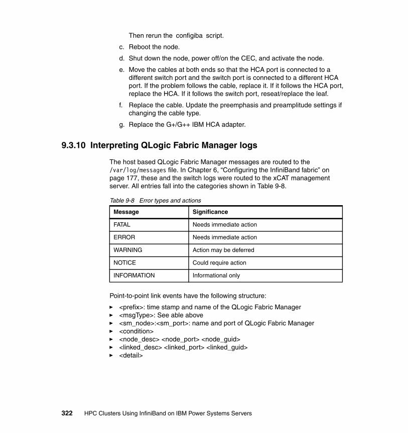
Then rerun the configiba script.
c. Reboot the node.
d. Shut down the node, power off/on the CEC, and activate the node.
e. Move the cables at both ends so that the HCA port is connected to a different switch port and the switch port is connected to a different HCA port. If the problem follows the cable, replace it. If it follows the HCA port, replace the HCA. If it follows the switch port, reseat/replace the leaf.
f. Replace the cable. Update the preemphasis and preamplitude settings if changing the cable type.
g. Replace the G+/G++ IBM HCA adapter.
9.3.10 Interpreting QLogic Fabric Manager logs
The host based QLogic Fabric Manager messages are routed to the /var/log/messages file. In Chapter 6, “Configuring the InfiniBand fabric” on page 177, these and the switch logs were routed to the xCAT management server. All entries fall into the categories shown in Table 9-8.
Table 9-8 Error types and actions
Point-to-point link events have the following structure:
� <prefix>: time stamp and name of the QLogic Fabric Manager� <msgType>: See able above� <sm_node>:<sm_port>: name and port of QLogic Fabric Manager� <condition>� <node_desc> <node_port> <node_guid>� <linked_desc> <linked_port> <linked_guid>� <detail>
Message Significance
FATAL Needs immediate action
ERROR Needs immediate action
WARNING Action may be deferred
NOTICE Could require action
INFORMATION Informational only
322 HPC Clusters Using InfiniBand on IBM Power Systems Servers

Example 9-31 shows an entry that follows this structure.
Example 9-31 Log event
May 15 17:58:14 fm01 iview_sm[3705]: fm01; MSG:NOTICE|SM:fm01:port 2|COND:#4 Disappearance from fabric|NODE:IBM G2 Logical HCA :port 2:0x0002550010b40801|LINKEDTO:IBM G2 Logical Switch 2:port 2:0x0002550010b40803|DETAIL:Node type: hca
The SM, BM, PM, and FE application events generate entries in /var/log/messages with slightly different formats but similar severity levels. Example 9-32 shows how the stop and start sequences are logged.
Example 9-32 Stop and start sequences for Fabric Manager
May 13 11:14:04 fm01 iview_sm[3297]: INFINIINFO [0x2ad50c7ab220]: SM: sm_control_shutdown: turning off isSm bit in portInfo 0May 13 11:14:04 fm01 shutdown: Shutting down process ID: 3297 for mgr: sm instance: 0May 13 11:14:04 fm01 iview_sm[3297]: fm01; MSG:NOTICE|SM:fm01:port 1|COND:#7 SM shutdown|NODE:fm01:port 1:0x00066a00a000edd0|DETAIL:(null)May 13 11:14:04 fm01 iview_sm[3297]: INFINIINFO [0x42804940]: APP: sa_Trap: Received an (IS_SM off) CAPABILITYMASK CHANGE [0x02510A68] trap from LID 0x0018, TID=0x0000000000000003 0
May 13 11:14:32 fm01 sm[5752]: Infinicon Systems Inc. Subnet manager starting up. filter: 0 trace ffffffffMay 13 11:14:32 fm01 iview_sm[5752]: Using dynamic packet lifetime values 16, 17, 17, 18, 18, 18, 18, 19, 19May 13 11:14:32 fm01 iview_sm[5752]: INFINIINFO [0x2ab841213220]: APP: SM: SM configured for 2560 END PORTS, GidPrefix=0xfe80000000000000, Key=0x0000000000000000, MKey=0x0000000000000000 : protect_level=1 : lease=0 seconds, dbsync interval=900 seconds 0
Example 9-33 shows how the Standby Fabric Manager checks to see whether the master is still available.
Example 9-33 Master/standby check
May 16 08:19:10 fm01 iview_sm[30949]: INFINIINFO [0x42804940]: APP: sm_check_Master: Master SM[0x00066a01a000ed7c] at LID=0x18 has priority[6] and smKey [0x0000000000000000] 0
Chapter 9. Fabric management and monitoring 323

Example 9-34 shows a situation when the Fabric Manager is overloaded. This can happen when a significant number changes take place in the fabric and the manager initiates a sweep when a routine sweep is already in progress. Recycle the iview_sm instances to clear this up.
Example 9-34 Overloaded Fabric Manager
May 15 19:04:57 fm01 iview_sm[5293]: WARN [0x40800940]: SA: sa_PathRecord: too many records for SA_CM_GET 16
Example 9-35 shows the sweep process. The sweeps check for topology assignments and paths, activate this topology, update the databases, and perform multicast setup. They occur at the following intervals:
� Regular intervals throughout the day as defined in /etc/sysconfig/iview_fm.config via the SM_X_timer attribute.
� After the Fabric Manager process is started.
� It is triggered when significant changes are made to the fabric, such as rebooting a host, rebooting a switch, adding or removing cables, adding, or removing switch leafs or spines, and so on.
Example 9-35 Subnet manager sweep
May 16 16:01:05 fm01 iview_sm[3760]: INFINIINFO [0x42003940]: SM: TT: DISCOVERY CYCLE START. 0May 16 16:01:05 fm01 iview_sm[3760]: INFINIINFO [0x42003940]: SM: topology_discovery: START directed route exploration of fabric 0May 16 16:01:05 fm01 iview_sm[3760]: INFINIINFO [0x42003940]: SM: topology_discovery: END directed route exploration of fabric, elapsed time(usecs)= 162876 .......snippet........May 16 16:01:06 fm01 iview_sm[3760]: INFINIINFO [0x42003940]: SM: sm_set_all_mft: START MFT set for switches 0May 16 16:01:06 fm01 iview_sm[3760]: INFINIINFO [0x42003940]: SM: sm_set_all_mft: END SET MFT of switches, elapsed time(usecs)= 1022May 16 16:01:06 fm01 iview_sm[3760]: INFINIINFO [0x42003940]: APP: TT: DISCOVERY CYCLE END. 34 SWs, 30 HCAs, 30 end ports, 246 total ports, 2 SM(s), 1751 packets, 0 retries, 0.763 sec sweep 0May 16 16:01:06 fm01 iview_sm[3760]: fm01; MSG:INFORMATION|SM:fm01:port 1|COND:#12 Fabric Summary|NODE:fm01: port 1:0x0008f104039908cd|DETAIL:52 SWs, 30 HCAs, 30 end ports, 456 total ports, 2 SM(s)
324 HPC Clusters Using InfiniBand on IBM Power Systems Servers

At the end of the sweep there is a fabric summary. Table 9-9 explains how to calculate these values.
Table 9-9 7874-240 fabric summary
Entry Description Detailed description
SW Switch chips Each spine has two switch chips (A and B). A 7874-240 switch has six spines. This yields 12 SW.
Each leaf has 12 individual switch chips. This yields 12 SW.
If 28 nodes are connected to the switch, then the switch is connected to 28 logical switches. This yields 28 SW.
Therefore, the total is 52.
HCAs Number of physical HCA connections (both PCI and GX)
There are two PCI HCA connections from the SM.
There are 28 GX HCA connections from the servers.
Therefore, this yields 30.
End ports Number of physical HCA connections (both PCI and GX)
Same as HCAs.
Total ports Each spine switch chip has 24 ports. Multiple this by two and this equals 48. Multiple this by six and you get the total number of leaf ports, which yields 288.
Then count the leaf to HCA (PCI and GX) and multiple by each end. So, 30 times 2 yields 60.
Then count the leaf to logical switch connections, which is 28, and multiple it by the two logical switches in the adapter, which yields 56.
Then add the SW number, 52, because the subnet manager uses port 0 to communicate with the switch chip.
In total this yields 456.
SM Number of subnet manager connections
On this instance there is one master and one standby subnet manager, not necessarily on the same Fabric Manager Server.
Chapter 9. Fabric management and monitoring 325
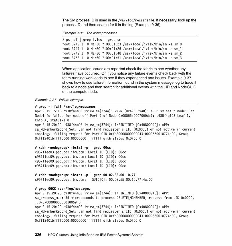
The SM process ID is used in the /var/log/message file. If necessary, look up the process ID and then search for it in the log (Example 9-36).
Example 9-36 The iview processes
# ps -ef | grep iview | grep smroot 3742 1 0 Mar30 ? 00:01:23 /usr/local/iview/bin/sm -e sm_0root 3744 1 0 Mar30 ? 00:01:26 /usr/local/iview/bin/sm -e sm_1root 3749 1 0 Mar30 ? 00:01:48 /usr/local/iview/bin/sm -e sm_2root 3752 1 0 Mar30 ? 00:01:51 /usr/local/iview/bin/sm -e sm_3
When application issues are reported check the fabric to see whether any failures have occurred. Or if you notice any failure events check back with the team running workloads to see if they experienced any issues. Example 9-37 shows how to use failure information found in the system message log to trace it back to a node and then search for additional events with the LID and NodeGUID of the compute node.
Example 9-37 Failure example
# grep -i fail /var/log/messagesApr 2 15:15:18 c938f4nm02 iview_sm[3744]: WARN [0x42003940]: APP: sm_setup_node: Get NodeInfo failed for node off Port 9 of Node 0x00066a0007000da7: c938f4ql03 Leaf 1, Chip A, status=1 0Apr 2 15:20:20 c938f4nm02 iview_sm[3744]: INFINIINFO [0x40800940]: APP: sa_McMemberRecord_Set: Can not find requester's LID (0x00CC) or not active in current topology, failing request for Port GID 0xfe80000000000043:0002550010774a00, Group 0xff12401bffff0000:00000000ffffffff with status 0x0700 0
# xdsh <nodegroup> ibstat -p | grep 00ccc957f1ec03.ppd.pok.ibm.com: Local ID (LID): 00ccc957f1ec09.ppd.pok.ibm.com: Local ID (LID): 00ccc957f1ec09.ppd.pok.ibm.com: Local ID (LID): 00ccc957f1ec09.ppd.pok.ibm.com: Local ID (LID): 00cc
# xdsh <nodegroup> ibstat -p | grep 00.02.55.00.10.77c957f1ec09.ppd.pok.ibm.com: GUID[0]: 00.02.55.00.10.77.4a.00
# grep 00CC /var/log/messagesApr 2 15:20:20 c938f4nm02 iview_sm[3744]: INFINIINFO [0x40800940]: APP: sa_process_mad: 55 microseconds to process DELETE[MCMEMBER] request from LID 0x00CC, TID=0x0000000000010059 0Apr 2 15:20:20 c938f4nm02 iview_sm[3744]: INFINIINFO [0x40800940]: APP: sa_McMemberRecord_Set: Can not find requester's LID (0x00CC) or not active in current topology, failing request for Port GID 0xfe80000000000043:0002550010774a00, Group 0xff12401bffff0000:00000000ffffffff with status 0x0700 0
326 HPC Clusters Using InfiniBand on IBM Power Systems Servers
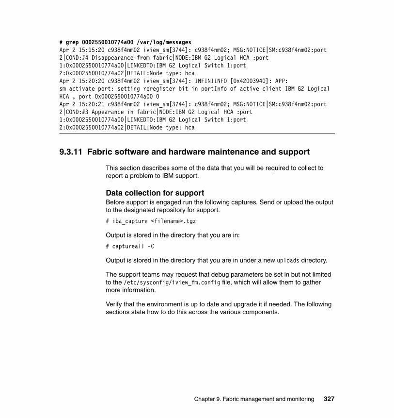
# grep 0002550010774a00 /var/log/messagesApr 2 15:15:20 c938f4nm02 iview_sm[3744]: c938f4nm02; MSG:NOTICE|SM:c938f4nm02:port 2|COND:#4 Disappearance from fabric|NODE:IBM G2 Logical HCA :port 1:0x0002550010774a00|LINKEDTO:IBM G2 Logical Switch 1:port 2:0x0002550010774a02|DETAIL:Node type: hcaApr 2 15:20:20 c938f4nm02 iview_sm[3744]: INFINIINFO [0x42003940]: APP: sm_activate_port: setting reregister bit in portInfo of active client IBM G2 Logical HCA , port 0x0002550010774a00 0Apr 2 15:20:21 c938f4nm02 iview_sm[3744]: c938f4nm02; MSG:NOTICE|SM:c938f4nm02:port 2|COND:#3 Appearance in fabric|NODE:IBM G2 Logical HCA :port 1:0x0002550010774a00|LINKEDTO:IBM G2 Logical Switch 1:port 2:0x0002550010774a02|DETAIL:Node type: hca
9.3.11 Fabric software and hardware maintenance and support
This section describes some of the data that you will be required to collect to report a problem to IBM support.
Data collection for supportBefore support is engaged run the following captures. Send or upload the output to the designated repository for support.
# iba_capture <filename>.tgz
Output is stored in the directory that you are in:
# captureall -C
Output is stored in the directory that you are in under a new uploads directory.
The support teams may request that debug parameters be set in but not limited to the /etc/sysconfig/iview_fm.config file, which will allow them to gather more information.
Verify that the environment is up to date and upgrade it if needed. The following sections state how to do this across the various components.
Chapter 9. Fabric management and monitoring 327
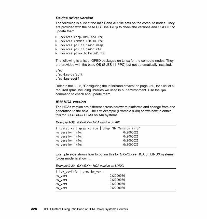
Device driver versionThe following is a list of the InfiniBand AIX file sets on the compute nodes. They are provided with the base OS. Use lslpp to check the versions and installp to update them.
� devices.chrp.IBM.lhca.rte� devices.common.IBM.ib.rte� devices.pci.b315445a.diag� devices.pci.b315445a.rte� devices.pciex.b3157862.rte
The following is a list of OFED packages on Linux for the compute nodes. They are provided with the base OS (SLES 11 PPC) but not automatically installed.
ofedofed-kmp-defaultofed-kmp-ppc64
Refer to the 8.2.5, “Configuring the InfiniBand drivers” on page 250, for a list of all required rpms including libraries we used in our environment. Use the rpm command to check and update them.
IBM HCA versionThe HCAs version are different across hardware platforms and change from one generation to the next. The first example (Example 9-38) shows how to obtain this for GX+/GX++ HCAs on AIX systems.
Example 9-38 GX+/GX++ HCA version on AIX
# ibstat -v | grep -p iba | grep "Hw Version info"Hw Version info: 0x2000021Hw Version info: 0x2000021Hw Version info: 0x2000021Hw Version info: 0x2000021
Example 9-39 shows how to obtain this for GX+/GX++ HCA on LINUX systems (older model is shown).
Example 9-39 GX+/GX++ HCA version on LINUX
# ibv_devinfo | grep hw_ver:hw_ver: 0x2000020hw_ver: 0x2000020hw_ver: 0x2000020hw_ver: 0x2000020
328 HPC Clusters Using InfiniBand on IBM Power Systems Servers
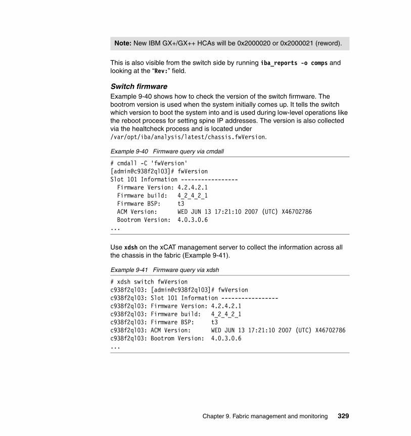
This is also visible from the switch side by running iba_reports -o comps and looking at the “Rev:” field.
Switch firmwareExample 9-40 shows how to check the version of the switch firmware. The bootrom version is used when the system initially comes up. It tells the switch which version to boot the system into and is used during low-level operations like the reboot process for setting spine IP addresses. The version is also collected via the healtcheck process and is located under /var/opt/iba/analysis/latest/chassis.fwVersion.
Example 9-40 Firmware query via cmdall
# cmdall -C 'fwVersion'[admin@c938f2ql03]# fwVersionSlot 101 Information ----------------- Firmware Version: 4.2.4.2.1 Firmware build: 4_2_4_2_1 Firmware BSP: t3 ACM Version: WED JUN 13 17:21:10 2007 (UTC) X46702786 Bootrom Version: 4.0.3.0.6...
Use xdsh on the xCAT management server to collect the information across all the chassis in the fabric (Example 9-41).
Example 9-41 Firmware query via xdsh
# xdsh switch fwVersionc938f2ql03: [admin@c938f2ql03]# fwVersionc938f2ql03: Slot 101 Information -----------------c938f2ql03: Firmware Version: 4.2.4.2.1c938f2ql03: Firmware build: 4_2_4_2_1c938f2ql03: Firmware BSP: t3c938f2ql03: ACM Version: WED JUN 13 17:21:10 2007 (UTC) X46702786c938f2ql03: Bootrom Version: 4.0.3.0.6...
Note: New IBM GX+/GX++ HCAs will be 0x2000020 or 0x2000021 (reword).
Chapter 9. Fabric management and monitoring 329
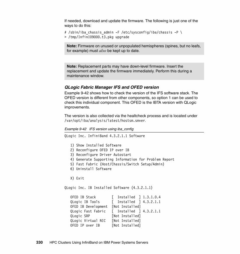
If needed, download and update the firmware. The following is just one of the ways to do this:
# /sbin/iba_chassis_admin -F /etc/sysconfig/iba/chassis -P \ > /tmp/InfinIO9000.t3.pkg upgrade
QLogic Fabric Manager IFS and OFED versionExample 9-42 shows how to check the version of the IFS software stack. The OFED version is different from other components, so option 1 can be used to check this individual component. This OFED is the IBTA version with QLogic improvements.
The version is also collected via the healtcheck process and is located under /var/opt/iba/analysis/latest/hostsm.smver.
Example 9-42 IFS version using iba_config
QLogic Inc. InfiniBand 4.3.2.1.1 Software
1) Show Installed Software 2) Reconfigure OFED IP over IB 3) Reconfigure Driver Autostart 4) Generate Supporting Information for Problem Report 5) Fast Fabric (Host/Chassis/Switch Setup/Admin) 6) Uninstall Software
X) Exit
QLogic Inc. IB Installed Software (4.3.2.1.1)
OFED IB Stack [ Installed ] 1.3.1.0.4 QLogic IB Tools [ Installed ] 4.3.2.1.1 OFED IB Development [Not Installed] QLogic Fast Fabric [ Installed ] 4.3.2.1.1 QLogic SRP [Not Installed] QLogic Virtual NIC [Not Installed] OFED IP over IB [Not Installed]
Note: Firmware on unused or unpopulated hemispheres (spines, but no leafs, for example) must also be kept up to date.
Note: Replacement parts may have down-level firmware. Insert the replacement and update the firmware immediately. Perform this during a maintenance window.
330 HPC Clusters Using InfiniBand on IBM Power Systems Servers

OFED SDP [Not Installed] OFED uDAPL [Not Installed] MVAPICH for gcc [Not Installed] MVAPICH2 for gcc [Not Installed] OpenMPI for gcc [Not Installed] MPI Source [Not Installed] QLogic FM [ Installed ] 4.3.2.1.1 OFED RDS [Not Installed] OFED SRP [Not Installed] OFED SRP Target [Not Installed] OFED iSER [Not Installed] OFED iWARP [Not Installed] OFED Open SM [Not Installed] OFED Debug Info [Not Installed]
The version information is collected via the all_analysis process. Use xdsh on the xCAT management server to collect the information across all the host based QLogic Fabric Managers (Example 9-43).
Example 9-43 HSM version collected using xCAT
# xdsh hsm cat /var/opt/iba/analysis/latest/hostsm.smverfm01: iview_fm-4_3_2_1-1fm02: iview_fm-4_3_2_1-1
If needed, download and update IFS. Untar the package and locate the INSTALL script. If any settings must be modified after the install run iba_config.
Check for OS-related issuesA quick way to check for error messages not related to the QLogic FastFabric Toolset is to exclude all messages with “iview_”, or grep for ‘kernel’ messages. Example 9-44 shows a low memory issue.
Example 9-44 Memory kernel message
# grep -i kernel /var/log/messagesMar 27 08:22:27 fm01 kernel: Out of memory: Killed process 13496 (parse-metadata).Mar 27 08:22:30 fm01 kernel: Out of memory: Killed process 11135 (gdmgreeter).Mar 27 08:23:28 fm01 kernel: Out of memory: Killed process 13547 (update-status).Mar 27 08:23:29 fm01 kernel: Out of memory: Killed process 13494 (zmd).Mar 27 13:15:21 fm01 kernel: Out of memory: Killed process 13611 (gdmgreeter).Mar 27 13:15:23 fm01 kernel: Out of memory: Killed process 3760 (bm).Mar 28 03:45:16 fm01 kernel: Out of memory: Killed process 14329 (gdmgreeter).Mar 28 03:45:17 fm01 kernel: Out of memory: Killed process 11323 (bm).
Chapter 9. Fabric management and monitoring 331
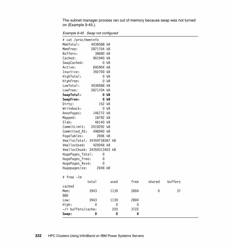
The subnet manager process ran out of memory because swap was not turned on (Example 9-45.).
Example 9-45 Swap not configured
# cat /proc/meminfoMemTotal: 4038588 kBMemFree: 2871704 kBBuffers: 38680 kBCached: 901940 kBSwapCached: 0 kBActive: 695904 kBInactive: 392700 kBHighTotal: 0 kBHighFree: 0 kBLowTotal: 4038588 kBLowFree: 2871704 kBSwapTotal: 0 kBSwapFree: 0 kBDirty: 152 kBWriteback: 0 kBAnonPages: 146772 kBMapped: 18792 kBSlab: 46140 kBCommitLimit: 2019292 kBCommitted_AS: 498940 kBPageTables: 2696 kBVmallocTotal: 34359738367 kBVmallocUsed: 420048 kBVmallocChunk: 34359313403 kBHugePages_Total: 0HugePages_Free: 0HugePages_Rsvd: 0Hugepagesize: 2048 kB
# free -lm total used free shared buffers cachedMem: 3943 1139 2804 0 37 880Low: 3943 1139 2804High: 0 0 0-/+ buffers/cache: 220 3722Swap: 0 0 0
332 HPC Clusters Using InfiniBand on IBM Power Systems Servers

Swap was enabled successfully with the swapon command, but it did not start after a reboot. Additional troubleshooting revealed a known issue that can happen during a migration from SLES 10 SP1 to SP2 whereby the swap entry in /etc/fstab was pointing to an invalid disk (Example 9-46).
Example 9-46 /etc/fstab output on host based QLogic Fabric Manager
# grep swap cat /etc/fstab/dev/disk/by-id/scsi-SServeRA_Drive_1_1065D354-part1 swap swap defaults 0 0# ls -l /dev/disk/by-id/scsi-SServeRA_Drive*lrwxrwxrwx 1 root root 9 May 6 11:51 /dev/disk/by-id/scsi-SServeRA_Drive_1_1065D449 -> ../../sdalrwxrwxrwx 1 root root 10 May 6 11:51 /dev/disk/by-id/scsi-SServeRA_Drive_1_1065D449-part1 -> ../../sda1lrwxrwxrwx 1 root root 10 May 6 11:51 /dev/disk/by-id/scsi-SServeRA_Drive_1_1065D449-part2 -> ../../sda2
After the link was updated to point to the proper device swap stayed on after a reboot.
The memory usage for the host based QLogic Fabric Manager processes can be checked using the following:
# ps -o pid,rsz,vsz,cmd -Cs sm,bm,pm,fe
QLogic Fabric Manager backupThe following is a list of recommended files and directories to back up:
� /etc/sysconfig/iview_fm.config� /etc/sysconfig/fastfabric.conf� /etc/sysconfig/iba/ports� /etc/sysconfig/iba/chassis� /etc/sysconfig/iba/iba_mon.conf� /etc/sysconfig/iba/*topology* (configured per each subnet)� /var/log/messages*� /var/opt/iba/analysis/*� test.res and log/test.log 3
3 These will be located wherever the fastfabric TUI is run from.
Note: Backup custom scripts can be used to manage the environment.
Chapter 9. Fabric management and monitoring 333

9.3.12 Failover and recovery scenarios
This section walks through failover and recovery scenarios. It also provides information about how the events impact the fabric and applications (if any). In some examples a basic all-to-all test was used to monitor user workload during the recovery scenarios. The intent is to see whether the job was impacted from a connectivity and performance perspective. In this example the normal state was approximately 9.000e-00 (this is not meant to make any performance claims). The output shows how the values increased when components were pulled out and in and how it recovered after each event.
Cable pulls and replacementsA cable pull or replacement can take place while the system is up and running. However, that link will no longer be usable by user workload. When pulled, the link status will go down and the node will leave the multicast group for that subnet. LID and other fabric assignments will stay the same. The link should recover without any manual intervention after it is plugged back in.
Switch power supply reseat or failureA redundant power supply replacement is nondisruptive. The switch CLI command hwMonitor should report the device as NOT PRESENT and log an entry in the switch log and syslog file. After it is replaced hwMonitor should report a normal status for that device.
Switch fan reseat or failureA redundant fan replacement is nondisruptive. When removed, an orange light should appear in the fan slot. The switch CLI command hwCheck should report the device as offline and log an entry in the switch log and syslog file. After it is replaced hwCheck should report a “Chassis hardware status: GOOD” status.
Switch reboots/power offA switch reboot is disruptive to the subnet on the fabric and should be performed during a maintenance window if possible. Depending on the size of the switch the
Note: In AIX, GPFS should run over the multilink device ml0. In this case one link going down should not be a problem.
In Linux ml0 is not available, so normally we use the ib0 interface. In this case if we take ib0 down GPFS may unmount the file system on the node or create waiters depends on the failover configuration.
Attention: IB spec does not guarantee that you will get the same LID after cable unplug/plug (most likely, but this in not guaranteed).
334 HPC Clusters Using InfiniBand on IBM Power Systems Servers
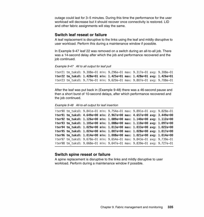
outage could last for 3–5 minutes. During this time the performance for the user workload will decrease but it should recover once connectivity is restored. LID and other fabric assignments will stay the same.
Switch leaf reseat or failureA leaf replacement is disruptive to the links using the leaf and mildly disruptive to user workload. Perform this during a maintenance window if possible.
In Example 9-47 leaf 22 was removed on a switch during an all-to-all job. There was a 14-second delay after which the job and performance recovered and the job continued.
Example 9-47 All to all output for leaf pull
iter21 tm_taks0: 9.308e-01 min: 9.296e-01 max: 9.317e-01 avg: 9.308e-01iter22 tm_taks0: 1.428e+01 min: 1.425e+01 max: 1.428e+01 avg: 1.426e+01iter23 tm_taks0: 9.779e-01 min: 9.620e-01 max: 9.807e-01 avg: 9.708e-01
After the leaf was put back in (Example 9-48) there was a 46-second pause and then a short burst of 10-second delays, after which performance recovered and the job continued.
Example 9-48 All-to-all output for leaf insertion
iter90 tm_taks0: 9.841e-01 min: 9.754e-01 max: 9.891e-01 avg: 9.828e-01iter91 tm_taks0: 4.649e+00 min: 2.967e+00 max: 4.657e+00 avg: 3.449e+00iter92 tm_taks0: 1.126e+00 min: 1.089e+00 max: 1.140e+00 avg: 1.112e+00iter93 tm_taks0: 1.105e+00 min: 1.088e+00 max: 1.110e+00 avg: 1.097e+00iter94 tm_taks0: 1.029e+00 min: 1.013e+00 max: 1.033e+00 avg: 1.022e+00iter95 tm_taks0: 1.024e+00 min: 1.007e+00 max: 1.028e+00 avg: 1.017e+00iter96 tm_taks0: 1.014e+00 min: 1.008e+00 max: 1.021e+00 avg: 1.014e+00iter97 tm_taks0: 9.678e-01 min: 9.654e-01 max: 9.843e-01 avg: 9.739e-01iter98 tm_taks0: 9.668e-01 min: 9.647e-01 max: 9.839e-01 avg: 9.727e-01
Switch spine reseat or failureA spine replacement is disruptive to the links and mildly disruptive to user workload. Perform during a maintenance window if possible.
Chapter 9. Fabric management and monitoring 335

In Example 9-49 spine 2 (the master) was removed. There was a 21-second pause, after which the performance recovered and the job continued.
Example 9-49 All-to-all output for spine pull
iter75 tm_taks0: 9.297e-01 min: 9.297e-01 max: 9.319e-01 avg: 9.306e-01iter76 tm_taks0: 2.180e+01 min: 2.180e+01 max: 2.180e+01 avg: 2.180e+01iter77 tm_taks0: 9.302e-01 min: 9.298e-01 max: 9.312e-01 avg: 9.305e-01
When the spine was put in (Example 9-50) there was a 14-second pause, after which performance recovered and the job continued. As the spine rebooted there was a 17-second pause, after which performance recovered and the job continued. Then as spine 2 came back as a slave (spine 1 was now the new master) there was a 12-second pause, after which performance recovered and the job continued.
Example 9-50 All-to-all output for spine insertion
iter23 tm_taks0: 9.305e-01 min: 9.291e-01 max: 9.310e-01 avg: 9.304e-0iter24 tm_taks0: 9.305e-01 min: 9.299e-01 max: 1.460e+01 avg: 4.406e+00iter25 tm_taks0: 9.339e-01 min: 9.325e-01 max: 9.352e-01 avg: 9.340e-01iter40 tm_taks0: 9.322e-01 min: 9.301e-01 max: 9.338e-01 avg: 9.316e-01iter41 tm_taks0: 1.750e+01 min: 1.749e+01 max: 1.750e+01 avg: 1.750e+01iter42 tm_taks0: 9.302e-01 min: 9.298e-01 max: 9.308e-01 avg: 9.304e-01iter48 tm_taks0: 9.299e-01 min: 9.299e-01 max: 9.313e-01 avg: 9.305e-01iter49 tm_taks0: 9.304e-01 min: 9.303e-01 max: 1.239e+01 avg: 9.295e+00iter50 tm_taks0: 9.332e-01 min: 9.305e-01 max: 9.336e-01 avg: 9.324e-01
In the next example (Example 9-51) spine 6 (master) was pulled out. There was a 22-second pause, after which the performance recovered and the job continued.
Example 9-51 All-to-all output for spine pull
iter33 tm_taks0: 9.299e-01 min: 9.297e-01 max: 9.315e-01 avg: 9.305e-01iter34 tm_taks0: 2.209e+01 min: 2.209e+01 max: 2.209e+01 avg: 2.209e+01iter35 tm_taks0: 9.318e-01 min: 9.307e-01 max: 9.327e-01 avg: 9.316e-01
336 HPC Clusters Using InfiniBand on IBM Power Systems Servers

When spine 6 was put back in (Example 9-52) there were a few 1-second blips and then a 14 s-second pause, after which performance recovered and job continued. As the spine rebooted there was a 44-second pause, after which performance recovered and the job continued briefly. Then because of a known issue with spine 6 (in any switch) it became master again and caused a 77-second pause, after which performance recovered and the job continued.
Example 9-52 All-to-all output for spine insertion
iter66 tm_taks0: 9.339e-01 min: 9.305e-01 max: 9.342e-01 avg: 9.326e-01iter67 tm_taks0: 1.359e+01 min: 1.358e+01 max: 1.359e+01 avg: 1.359e+01iter68 tm_taks0: 9.296e-01 min: 9.295e-01 max: 9.314e-01 avg: 9.305e-01iter75 tm_taks0: 9.303e-01 min: 9.300e-01 max: 9.353e-01 avg: 9.321e-01iter76 tm_taks0: 4.428e+01 min: 4.427e+01 max: 4.428e+01 avg: 4.428e+01iter77 tm_taks0: 9.301e-01 min: 9.301e-01 max: 9.312e-01 avg: 9.306e-01iter78 tm_taks0: 7.808e+01 min: 7.795e+01 max: 7.829e+01 avg: 7.813e+01iter79 tm_taks0: 9.304e-01 min: 9.300e-01 max: 9.316e-01 avg: 9.307e-01iter80 tm_taks0: 9.301e-01 min: 9.296e-01 max: 9.310e-01 avg: 9.304e-01
QLogic Fabric Manager failoverA subnet manager failover is mildly disruptive to the links and user workload. Perform this during a maintenance window if possible. When this occurs new LIDS are assigned to al the hosts. There are four per host because of the LMC value set to 2. The multcast group and IP over IB also goes down. The user workload recovers after a few minutes.
If you are using the elevated priority function, use the following commands on the new master server to fail back to the original master:
# /usr/local/iview/util/sm_diag -i 04 smRestorePriority
9.4 QLogic knowledge base
There are many procedures, hints, and best practice information regarding fabric management and troubleshooting available in the knowledge base on the QLogic Support Center Web page at:
http://solutions.qlogic.com/KanisaSupportSite/supportcentral/supportcentral.do?id=m1
You can check the What’s Popular section for information or answers to questions that customers have already asked. Articles such as “Show Me How: How is firmware installed on a switch?” will be listed in the this section.
4 The -i option identifies the SM instance. It will not always be 0.
Chapter 9. Fabric management and monitoring 337

Another section called Recently Added Content lists the articles that QLogic service representatives have added recently.
If you do not find what you are looking for, the search bar at the top of the page allows you to search on questions like What is the default HBA password? and limit your search to your particular product. The result will be a list of articles with the most likely answer to your question listed first. This search will not only check the knowledge base but also check the appropriate QLogic manuals for the information.
If all else fails to answer your question, there are forums that you can browse or add a post. There is a forum for InfiniBand Host and for InfiniBand Switches. The forum page also lists the newest discussion threads and the most popular discussion threads.
338 HPC Clusters Using InfiniBand on IBM Power Systems Servers
Chapter 10. Node management and monitoring
This chapter provides a quick reference to common management and monitoring techniques that can be used to manage and monitor nodes when implementing InfiniBand on IBM Power systems.
10
© Copyright IBM Corp. 2009. All rights reserved. 339
10.1 Managing compute nodes
This section lists some of the available tools that are provided with the various components of the IBM HPC offering.
10.1.1 xCAT2 InfiniBand management on AIX and Linux
The xCAT2 core package provides a collection of example InfiniBand-specific scripts to assist with the installation and management of InfiniBand-connected nodes. This collection of scripts includes some example monitoring scripts. These scripts are located in the /opt/xcat/share/xcat/ib/scripts directory on the xCAT2 management node.
The following is an overview and description of usage of these scripts. As these are only example scripts, most of them will require some modification to work in your environment.
The configiba postscriptThis xCAT2 postinstall script (postscript) is designed to allow the configuration of both single-port and dual-port InfiniBand HCAs on both AIX and Linux on IBM Power systems. Depending on your hardware, you must copy the corresponding script (one or two ports) in the /install/postscripts directory on the xCAT management node,
The script requires IP addresses and tables for all InfiniBand interfaces on each node, resolvable by the node during the running of the script (either during post-install or via an updatenode command).
It also requires that the intended IP label assigned to the InfiniBand interface is of the format <hostname>-ibN, where N is the number of the interface (starting with 0).
Additionally, for AIX, the ml0 interface also requires a resolvable IP label on the node during the running of the script. This device is created to enable the load balancing and failover of the IP over InfiniBand interfaces and is described in “AIX interface driver” on page 91.
Important: The functionality of the InfiniBand postscripts provided with the current xCAT level (2.2.1) may change in the future. Always check the configiba.README file in the /opt/xcat/share/xcat/ib/scripts directory.
340 HPC Clusters Using InfiniBand on IBM Power Systems Servers
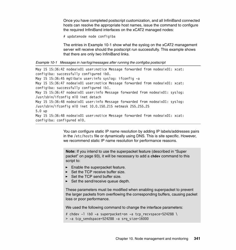
Once you have completed postscript customization, and all InfiniBand connected hosts can resolve the appropriate host names, issue the command to configure the required InfiniBand interfaces on the xCAT2 managed nodes:
# updatenode node configiba
The entries in Example 10-1 show what the syslog on the xCAT2 management server will receive should the postscript run successfully. This example shows that there are only two InfiniBand links.
Example 10-1 Messages in /var/log/messages after running the configiba postscript
May 15 15:36:42 nodeaix01 user:notice Message forwarded from nodeaix01: xcat: configiba: successfully configured ib0.May 15 15:36:45 mgtibaix user:info syslog: ifconfig -aMay 15 15:36:47 nodeaix01 user:notice Message forwarded from nodeaix01: xcat: configiba: successfully configured ib1.May 15 15:36:47 nodeaix01 user:info Message forwarded from nodeaix01: syslog: /usr/sbin/ifconfig ml0 inet detachMay 15 15:36:48 nodeaix01 user:info Message forwarded from nodeaix01: syslog: /usr/sbin/ifconfig ml0 inet 10.0.150.215 netmask 255.255.255.0 upMay 15 15:36:48 nodeaix01 user:notice Message forwarded from nodeaix01: xcat: configiba: configured ml0.
You can configure static IP name resolution by adding IP labels/addresses pairs in the /etc/hosts file or dynamically using DNS. This is site specific. However, we recommend static IP name resolution for performance reasons.
Note: If you intend to use the superpacket feature (described in “Super packet” on page 93), it will be necessary to add a chdev command to this script to:
� Enable the superpacket feature.� Set the TCP receive buffer size.� Set the TCP send buffer size.� Set the send/receive queue depth.
These parameters must be modified when enabling superpacket to prevent the larger packets from overflowing the corresponding buffers, causing packet loss or poor performance.
We used the following command to change the interface parameters:
# chdev -l ib0 -a superpacket=on -a tcp_recvspace=524288 \> -a tcp_sendspace=524288 -a srq_size=16000
Chapter 10. Node management and monitoring 341
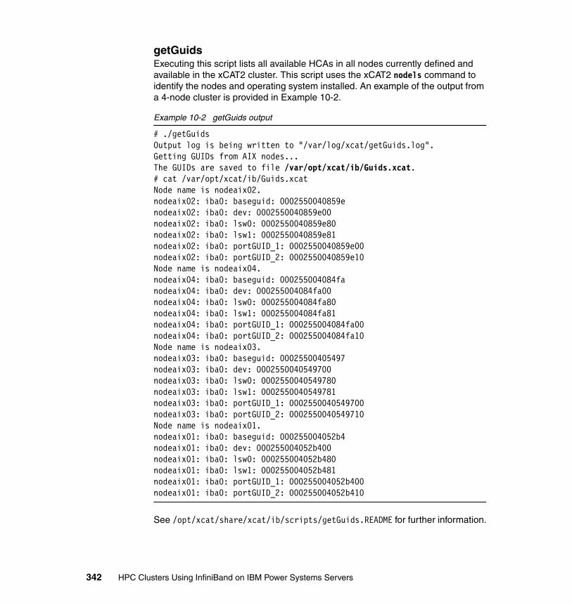
getGuidsExecuting this script lists all available HCAs in all nodes currently defined and available in the xCAT2 cluster. This script uses the xCAT2 nodels command to identify the nodes and operating system installed. An example of the output from a 4-node cluster is provided in Example 10-2.
Example 10-2 getGuids output
# ./getGuidsOutput log is being written to "/var/log/xcat/getGuids.log".Getting GUIDs from AIX nodes...The GUIDs are saved to file /var/opt/xcat/ib/Guids.xcat.# cat /var/opt/xcat/ib/Guids.xcatNode name is nodeaix02.nodeaix02: iba0: baseguid: 0002550040859enodeaix02: iba0: dev: 0002550040859e00nodeaix02: iba0: lsw0: 0002550040859e80nodeaix02: iba0: lsw1: 0002550040859e81nodeaix02: iba0: portGUID_1: 0002550040859e00nodeaix02: iba0: portGUID_2: 0002550040859e10Node name is nodeaix04.nodeaix04: iba0: baseguid: 000255004084fanodeaix04: iba0: dev: 000255004084fa00nodeaix04: iba0: lsw0: 000255004084fa80nodeaix04: iba0: lsw1: 000255004084fa81nodeaix04: iba0: portGUID_1: 000255004084fa00nodeaix04: iba0: portGUID_2: 000255004084fa10Node name is nodeaix03.nodeaix03: iba0: baseguid: 00025500405497nodeaix03: iba0: dev: 0002550040549700nodeaix03: iba0: lsw0: 0002550040549780nodeaix03: iba0: lsw1: 0002550040549781nodeaix03: iba0: portGUID_1: 0002550040549700nodeaix03: iba0: portGUID_2: 0002550040549710Node name is nodeaix01.nodeaix01: iba0: baseguid: 000255004052b4nodeaix01: iba0: dev: 000255004052b400nodeaix01: iba0: lsw0: 000255004052b480nodeaix01: iba0: lsw1: 000255004052b481nodeaix01: iba0: portGUID_1: 000255004052b400nodeaix01: iba0: portGUID_2: 000255004052b410
See /opt/xcat/share/xcat/ib/scripts/getGuids.README for further information.
342 HPC Clusters Using InfiniBand on IBM Power Systems Servers

Annotating logsThis sample script attempts to interpret message logs (collected by syslog) on the management host to provide sorted information by:
� Subnet manager� InfiniBand node� Chassis� FRU� Specific node
This script requires the files /var/opt/iba/analysis/baseline/fabric*links, which will not be created until after the all_analysis -b command has been successfully completed on the QLogic Fabric Manager servers (see Chapter 9, “Fabric management and monitoring” on page 283, for details on this command).
To create the required concatenated text file containing the output of this command from all Fabric Managers, run the following command:
# xdsh fm cat /var/opt/iba/analysis/baseline/fabric*links|xdshbak \> -x > /tmp/alllinks.txt
Here, fm is a group that includes all QLogic Fabric Manager servers that are defined in xCAT2.
The script also requires the output file created when the script getGuids was run.
The command output is shown in Example 10-3.
Example 10-3 Annotating logs output
# /opt/csm/samples/ib/annotatelog -f /var/log/allmessages -g \ > /var/opt/xcat/ib/Guids.xcat -l /tmp/alllinks.txt -A -------------------------------------------------------------------------------Reported by subnet manager: 'fm02:port 1'-------------------------------------------------------------------------------
May 21 12:03:18 fm02 iview_sm[4000]: fm02; MSG:INFORMATION|SM:fm02:port 1|COND:#12 Fabric Summary|NODE:fm02:port 1:0x00066a00a000ed6f|DETAIL:18 SWs, 10 HCAs, 10 end ports, 94 total ports, 2 SM(s)May 21 12:19:58 fm02 iview_sm[4000]: fm02; MSG:INFORMATION|SM:fm02:port 1|COND:#12 Fabric Summary|NODE:fm02:port 1:0x00066a00a000ed6f|DETAIL:18 SWs, 9 HCAs, 9 end ports, 92 total ports, 2 SM(s)..-------------------------------------------------------------------------------Reported by IB node: 'nodelnx03 :port 2:0x0002550040549711'- ehca0 <-> Not Found
Chapter 10. Node management and monitoring 343
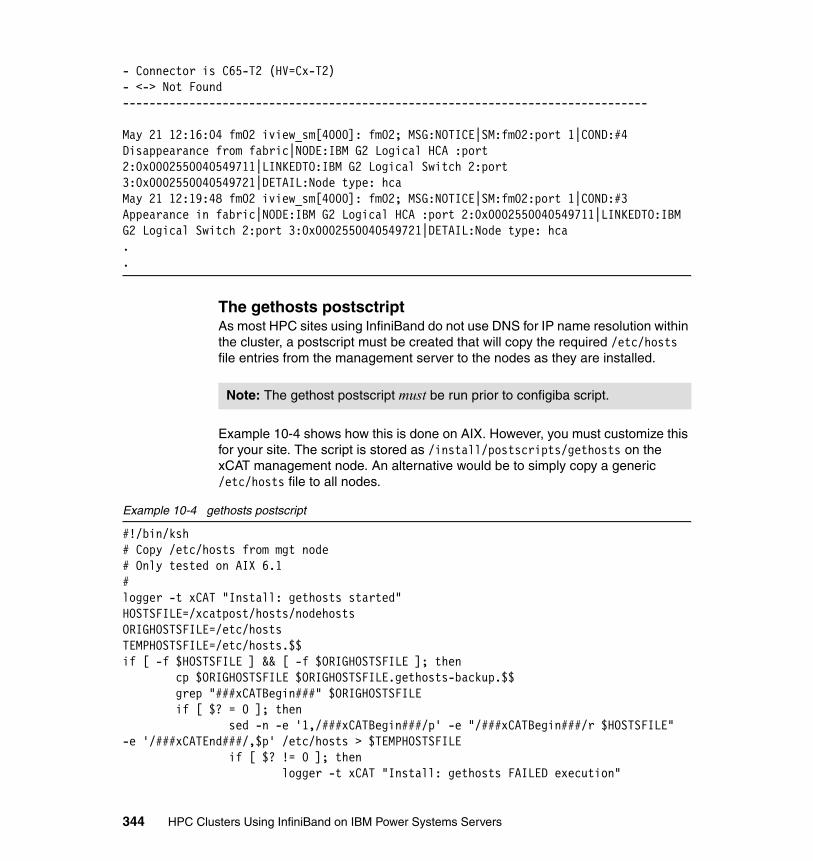
- Connector is C65-T2 (HV=Cx-T2)- <-> Not Found-------------------------------------------------------------------------------
May 21 12:16:04 fm02 iview_sm[4000]: fm02; MSG:NOTICE|SM:fm02:port 1|COND:#4 Disappearance from fabric|NODE:IBM G2 Logical HCA :port 2:0x0002550040549711|LINKEDTO:IBM G2 Logical Switch 2:port 3:0x0002550040549721|DETAIL:Node type: hcaMay 21 12:19:48 fm02 iview_sm[4000]: fm02; MSG:NOTICE|SM:fm02:port 1|COND:#3 Appearance in fabric|NODE:IBM G2 Logical HCA :port 2:0x0002550040549711|LINKEDTO:IBM G2 Logical Switch 2:port 3:0x0002550040549721|DETAIL:Node type: hca..
The gethosts postsctriptAs most HPC sites using InfiniBand do not use DNS for IP name resolution within the cluster, a postscript must be created that will copy the required /etc/hosts file entries from the management server to the nodes as they are installed.
Example 10-4 shows how this is done on AIX. However, you must customize this for your site. The script is stored as /install/postscripts/gethosts on the xCAT management node. An alternative would be to simply copy a generic /etc/hosts file to all nodes.
Example 10-4 gethosts postscript
#!/bin/ksh# Copy /etc/hosts from mgt node# Only tested on AIX 6.1#logger -t xCAT "Install: gethosts started"HOSTSFILE=/xcatpost/hosts/nodehostsORIGHOSTSFILE=/etc/hostsTEMPHOSTSFILE=/etc/hosts.$$if [ -f $HOSTSFILE ] && [ -f $ORIGHOSTSFILE ]; then cp $ORIGHOSTSFILE $ORIGHOSTSFILE.gethosts-backup.$$ grep "###xCATBegin###" $ORIGHOSTSFILE if [ $? = 0 ]; then sed -n -e '1,/###xCATBegin###/p' -e "/###xCATBegin###/r $HOSTSFILE" -e '/###xCATEnd###/,$p' /etc/hosts > $TEMPHOSTSFILE if [ $? != 0 ]; then logger -t xCAT "Install: gethosts FAILED execution"
Note: The gethost postscript must be run prior to configiba script.
344 HPC Clusters Using InfiniBand on IBM Power Systems Servers
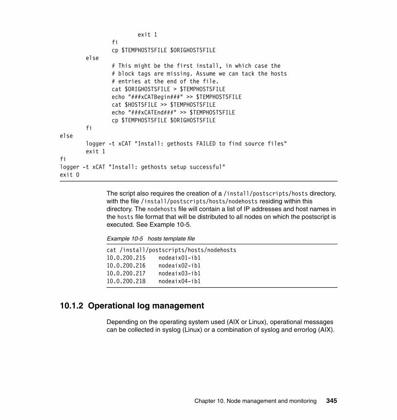
exit 1 fi cp $TEMPHOSTSFILE $ORIGHOSTSFILE else # This might be the first install, in which case the # block tags are missing. Assume we can tack the hosts # entries at the end of the file. cat $ORIGHOSTSFILE > $TEMPHOSTSFILE echo "###xCATBegin###" >> $TEMPHOSTSFILE cat $HOSTSFILE >> $TEMPHOSTSFILE echo "###xCATEnd###" >> $TEMPHOSTSFILE cp $TEMPHOSTSFILE $ORIGHOSTSFILE fielse logger -t xCAT "Install: gethosts FAILED to find source files" exit 1filogger -t xCAT "Install: gethosts setup successful"exit 0
The script also requires the creation of a /install/postscripts/hosts directory, with the file /install/postscripts/hosts/nodehosts residing within this directory. The nodehosts file will contain a list of IP addresses and host names in the hosts file format that will be distributed to all nodes on which the postscript is executed. See Example 10-5.
Example 10-5 hosts template file
cat /install/postscripts/hosts/nodehosts10.0.200.215 nodeaix01-ib110.0.200.216 nodeaix02-ib110.0.200.217 nodeaix03-ib110.0.200.218 nodeaix04-ib1
10.1.2 Operational log management
Depending on the operating system used (AIX or Linux), operational messages can be collected in syslog (Linux) or a combination of syslog and errorlog (AIX).
Chapter 10. Node management and monitoring 345
The syslog subsystemDuring the installation process, xCAT makes several changes to both the management server and, by default, the managed nodes. These changes are:
� Enable syslog (for AIX).
� Enable the receiving of remote syslog messages (for SLES).
� Configure the management server to log all messages to a single file (*.debug for AIX).
� Configure all xCAT2 client nodes (compute nodes) to send syslog messages to the xCAT2 management server.
This is done to ensure that there is a single collection point for all logs that might need to be reviewed by system administrators or automated scripts designed to parse these logs (for example, annotatelog).The configuration should be reviewed to ensure that the changes are acceptable to your site.
The volume of information that will be written to this log will be immense, with a large number of nodes, switches, and Fabric Managers, so serious consideration should be made towards:
� How much space is allocated to the storage of these logs.
� How often the logs are rotated.
� The amount of CPU and disk time that is required to parse the logs into anything approaching human-readable. (For example, several GiB of logs a day might require in the order of hours to process into a concise, readable report suitable for daily review.)
� Whether the site would be best served by sending all the data to a database for analysis by custom queries.
346 HPC Clusters Using InfiniBand on IBM Power Systems Servers
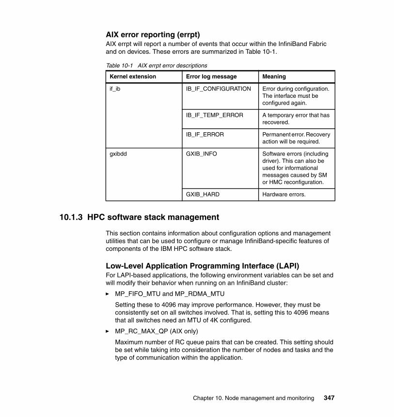
AIX error reporting (errpt)AIX errpt will report a number of events that occur within the InfiniBand Fabric and on devices. These errors are summarized in Table 10-1.
Table 10-1 AIX errpt error descriptions
10.1.3 HPC software stack management
This section contains information about configuration options and management utilities that can be used to configure or manage InfiniBand-specific features of components of the IBM HPC software stack.
Low-Level Application Programming Interface (LAPI) For LAPI-based applications, the following environment variables can be set and will modify their behavior when running on an InfiniBand cluster:
� MP_FIFO_MTU and MP_RDMA_MTU
Setting these to 4096 may improve performance. However, they must be consistently set on all switches involved. That is, setting this to 4096 means that all switches need an MTU of 4K configured.
� MP_RC_MAX_QP (AIX only)
Maximum number of RC queue pairs that can be created. This setting should be set while taking into consideration the number of nodes and tasks and the type of communication within the application.
Kernel extension Error log message Meaning
if_ib IB_IF_CONFIGURATION Error during configuration. The interface must be configured again.
IB_IF_TEMP_ERROR A temporary error that has recovered.
IB_IF_ERROR Permanent error. Recovery action will be required.
gxibdd GXIB_INFO Software errors (including driver). This can also be used for informational messages caused by SM or HMC reconfiguration.
GXIB_HARD Hardware errors.
Chapter 10. Node management and monitoring 347
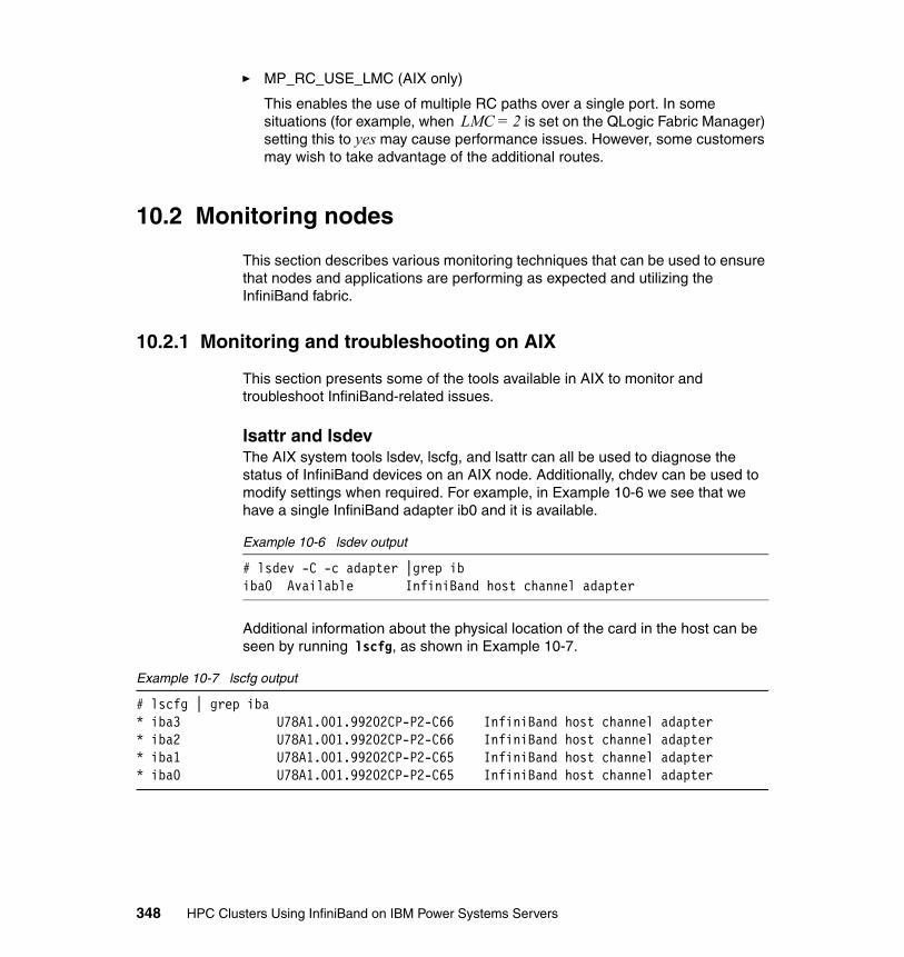
� MP_RC_USE_LMC (AIX only)
This enables the use of multiple RC paths over a single port. In some situations (for example, when LMC = 2 is set on the QLogic Fabric Manager) setting this to yes may cause performance issues. However, some customers may wish to take advantage of the additional routes.
10.2 Monitoring nodes
This section describes various monitoring techniques that can be used to ensure that nodes and applications are performing as expected and utilizing the InfiniBand fabric.
10.2.1 Monitoring and troubleshooting on AIX
This section presents some of the tools available in AIX to monitor and troubleshoot InfiniBand-related issues.
lsattr and lsdevThe AIX system tools lsdev, lscfg, and lsattr can all be used to diagnose the status of InfiniBand devices on an AIX node. Additionally, chdev can be used to modify settings when required. For example, in Example 10-6 we see that we have a single InfiniBand adapter ib0 and it is available.
Example 10-6 lsdev output
# lsdev -C -c adapter |grep ibiba0 Available InfiniBand host channel adapter
Additional information about the physical location of the card in the host can be seen by running lscfg, as shown in Example 10-7.
Example 10-7 lscfg output
# lscfg | grep iba* iba3 U78A1.001.99202CP-P2-C66 InfiniBand host channel adapter* iba2 U78A1.001.99202CP-P2-C66 InfiniBand host channel adapter* iba1 U78A1.001.99202CP-P2-C65 InfiniBand host channel adapter* iba0 U78A1.001.99202CP-P2-C65 InfiniBand host channel adapter
348 HPC Clusters Using InfiniBand on IBM Power Systems Servers

Basic information on devices can also be retrieved using lsattr, as shown in Example 10-8.
Example 10-8 lsattr output
# lsattr -El ml0alias4 N/A Truenetaddr 10.0.9.49 N/A Truenetmask 255.255.255.0 N/A Truestate up N/A True
When run against the ml0 device, it displays the IP information for the ML device. Configuration for ml0 can be changed with smitty inet or the chdev command, which is utilized by the configiba postscript.
The topas and nmon toolsThe topas tool is the standard stopping point for system administrators when seeking a system performance overview. For InfiniBand, IP over InfiniBand interfaces will be enumerated and statistics given. An example of the topas screen is given in Example 10-9.
Example 10-9 TOPAS output
Topas Monitor for host: gpfs01 EVENTS/QUEUES FILE/TTYWed May 27 18:17:13 2009 Interval: 2 Cswitch 17385 Readch 320 Syscall 35548 Writech 704CPU User% Kern% Wait% Idle% Physc Entc Reads 1 Rawin 0ALL 2.6 30.6 3.8 63.1 0.72 36.0 Writes 3 Ttyout 320 Forks 0 Igets 0Network KBPS I-Pack O-Pack KB-In KB-Out Execs 0 Namei 2Total 360.3K 5757.0 94.2K 525.6 359.8K Runqueue 2.5 Dirblk 0 Waitqueue 0.0Disk Busy% KBPS TPS KB-Read KB-Writ MEMORYTotal 0.0 177.3K 2841.0 177.3K 0.0 PAGING Real,MB 3072 Faults 12 % Comp 38FileSystem KBPS TPS KB-Read KB-Writ Steals 0 % Noncomp 4Total 0.3 1.5 0.3 0.0 PgspIn 0 % Client 4 PgspOut 0Name PID CPU% PgSp Owner PageIn 0 PAGING SPACEmmfsd64 380974 26.7 5.6 root PageOut 0 Size,MB 512CqKp 192606 2.7 0.4 root Sios 0 % Used 2topas 319710 0.1 2.3 root % Free 98hats_nim 466956 0.0 3.3 root NFS (calls/sec)hatsd 462890 0.0 9.3 root SerV2 0 WPAR Activ 0java 368844 0.0 49.0 pconsole CliV2 0 WPAR Total 0
Chapter 10. Node management and monitoring 349
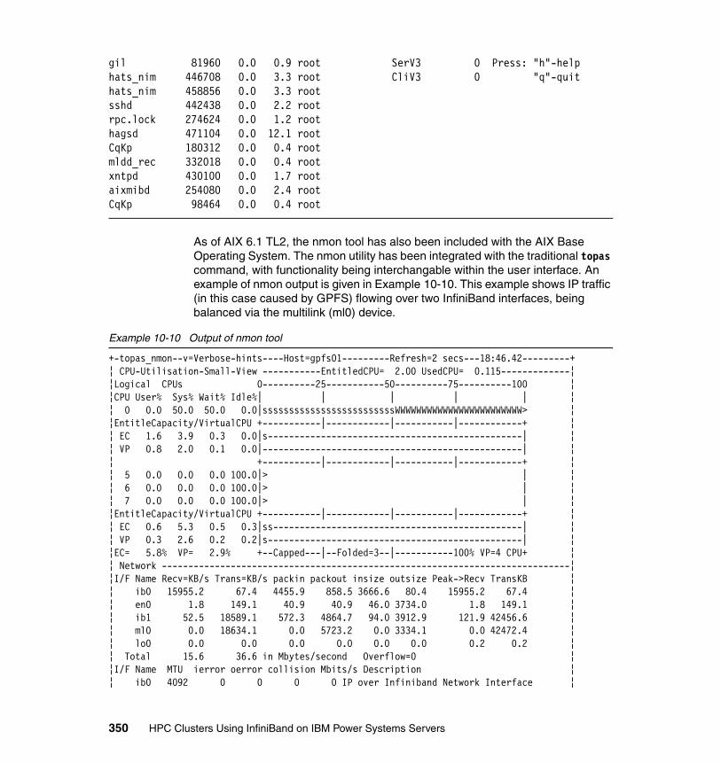
gil 81960 0.0 0.9 root SerV3 0 Press: "h"-helphats_nim 446708 0.0 3.3 root CliV3 0 "q"-quithats_nim 458856 0.0 3.3 rootsshd 442438 0.0 2.2 rootrpc.lock 274624 0.0 1.2 roothagsd 471104 0.0 12.1 rootCqKp 180312 0.0 0.4 rootmldd_rec 332018 0.0 0.4 rootxntpd 430100 0.0 1.7 rootaixmibd 254080 0.0 2.4 rootCqKp 98464 0.0 0.4 root
As of AIX 6.1 TL2, the nmon tool has also been included with the AIX Base Operating System. The nmon utility has been integrated with the traditional topas command, with functionality being interchangable within the user interface. An example of nmon output is given in Example 10-10. This example shows IP traffic (in this case caused by GPFS) flowing over two InfiniBand interfaces, being balanced via the multilink (ml0) device.
Example 10-10 Output of nmon tool
+-topas_nmon--v=Verbose-hints----Host=gpfs01---------Refresh=2 secs---18:46.42---------+¦ CPU-Utilisation-Small-View -----------EntitledCPU= 2.00 UsedCPU= 0.115-------------¦¦Logical CPUs 0----------25-----------50----------75----------100 ¦¦CPU User% Sys% Wait% Idle%| | | | | ¦¦ 0 0.0 50.0 50.0 0.0|sssssssssssssssssssssssssWWWWWWWWWWWWWWWWWWWWWWWW> ¦¦EntitleCapacity/VirtualCPU +-----------|------------|-----------|------------+ ¦¦ EC 1.6 3.9 0.3 0.0|s------------------------------------------------| ¦¦ VP 0.8 2.0 0.1 0.0|-------------------------------------------------| ¦¦ +-----------|------------|-----------|------------+ ¦¦ 5 0.0 0.0 0.0 100.0|> | ¦¦ 6 0.0 0.0 0.0 100.0|> | ¦¦ 7 0.0 0.0 0.0 100.0|> | ¦¦EntitleCapacity/VirtualCPU +-----------|------------|-----------|------------+ ¦¦ EC 0.6 5.3 0.5 0.3|ss-----------------------------------------------| ¦¦ VP 0.3 2.6 0.2 0.2|s------------------------------------------------| ¦¦EC= 5.8% VP= 2.9% +--Capped---|--Folded=3--|-----------100% VP=4 CPU+ ¦¦ Network -----------------------------------------------------------------------------¦¦I/F Name Recv=KB/s Trans=KB/s packin packout insize outsize Peak->Recv TransKB ¦¦ ib0 15955.2 67.4 4455.9 858.5 3666.6 80.4 15955.2 67.4 ¦¦ en0 1.8 149.1 40.9 40.9 46.0 3734.0 1.8 149.1 ¦¦ ib1 52.5 18589.1 572.3 4864.7 94.0 3912.9 121.9 42456.6 ¦¦ ml0 0.0 18634.1 0.0 5723.2 0.0 3334.1 0.0 42472.4 ¦¦ lo0 0.0 0.0 0.0 0.0 0.0 0.0 0.2 0.2 ¦¦ Total 15.6 36.6 in Mbytes/second Overflow=0 ¦¦I/F Name MTU ierror oerror collision Mbits/s Description ¦¦ ib0 4092 0 0 0 0 IP over Infiniband Network Interface ¦
350 HPC Clusters Using InfiniBand on IBM Power Systems Servers
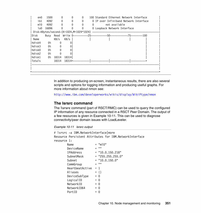
¦ en0 1500 0 0 0 100 Standard Ethernet Network Interface ¦¦ ib1 4092 0 0 0 0 IP over Infiniband Network Interface ¦¦ ml0 4092 0 0 0 0 not available ¦¦ lo0 16896 0 0 0 0 Loopback Network Interface ¦¦ Disk-KBytes/second-(K=1024,M=1024*1024) ---------------------------------------------¦¦Disk Busy Read Write 0----------25-----------50------------75--------100 ¦¦ Name KB/s KB/s | | | | | ¦¦hdisk4 0% 0 0| | ¦¦hdisk3 0% 0 0| | ¦¦hdisk0 0% 0 0| | ¦¦hdisk2 0% 0 0| | ¦¦hdisk1 0% 18314 18314| | ¦¦Totals 18314 18314+-----------|------------|-------------|----------+ ¦¦--------------------------------------------------------------------------------------¦¦ ¦+--------------------------------------------------------------------------------------+
In addition to producing on-screen, instantaneous results, there are also several scripts and options for logging information and producing useful graphs. For more information about nmon see:
http://www.ibm.com/developerworks/wikis/display/WikiPtype/nmon
The lsrsrc commandThe lsrsrc command (part of RSCT/RMC) can be used to query the configured IP information of any resource connected in a RSCT Peer Domain. The output of a few resources is given in Example 10-11. This can be used to diagnose connectivity/peer domain issues with LoadLeveler.
Example 10-11 lsrsrc output
# lsrsrc -a IBM.NetworkInterface|moreResource Persistent Attributes for IBM.NetworkInterfaceresource 1: Name = "ml0" DeviceName = "" IPAddress = "10.0.150.218" SubnetMask = "255.255.255.0" Subnet = "10.0.150.0" CommGroup = "" HeartbeatActive = 1 Aliases = {} DeviceSubType = 0 LogicalID = 0 NetworkID = 0 NetworkID64 = 0 PortID = 0
Chapter 10. Node management and monitoring 351
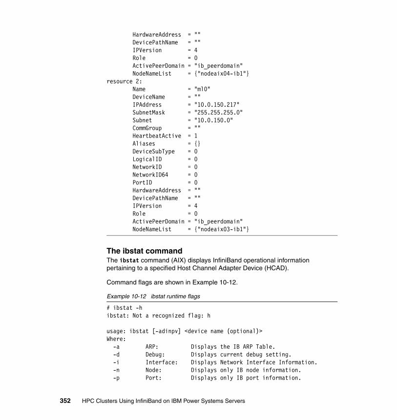
HardwareAddress = "" DevicePathName = "" IPVersion = 4 Role = 0 ActivePeerDomain = "ib_peerdomain" NodeNameList = {"nodeaix04-ib1"}resource 2: Name = "ml0" DeviceName = "" IPAddress = "10.0.150.217" SubnetMask = "255.255.255.0" Subnet = "10.0.150.0" CommGroup = "" HeartbeatActive = 1 Aliases = {} DeviceSubType = 0 LogicalID = 0 NetworkID = 0 NetworkID64 = 0 PortID = 0 HardwareAddress = "" DevicePathName = "" IPVersion = 4 Role = 0 ActivePeerDomain = "ib_peerdomain" NodeNameList = {"nodeaix03-ib1"}
The ibstat commandThe ibstat command (AIX) displays InfiniBand operational information pertaining to a specified Host Channel Adapter Device (HCAD).
Command flags are shown in Example 10-12.
Example 10-12 ibstat runtime flags
# ibstat -hibstat: Not a recognized flag: h
usage: ibstat [-adinpv] <device name (optional)>Where: -a ARP: Displays the IB ARP Table. -d Debug: Displays current debug setting. -i Interface: Displays Network Interface Information. -n Node: Displays only IB node information. -p Port: Displays only IB port information.
352 HPC Clusters Using InfiniBand on IBM Power Systems Servers
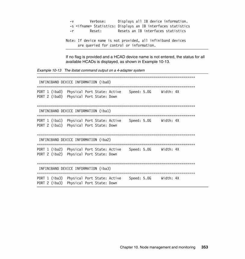
-v Verbose: Displays all IB device information. -s <ifname> Statistics: Displays an IB interfaces statistics -r Reset: Resets an IB interfaces statistics
Note: If device name is not provided, all infiniband devices are queried for control or information.
If no flag is provided and a HCAD device name is not entered, the status for all available HCADs is displayed, as shown in Example 10-13.
Example 10-13 The ibstat command output on a 4-adapter system
=============================================================================== INFINIBAND DEVICE INFORMATION (iba0)===============================================================================PORT 1 (iba0) Physical Port State: Active Speed: 5.0G Width: 4XPORT 2 (iba0) Physical Port State: Down
=============================================================================== INFINIBAND DEVICE INFORMATION (iba1)===============================================================================PORT 1 (iba1) Physical Port State: Active Speed: 5.0G Width: 4XPORT 2 (iba1) Physical Port State: Down
=============================================================================== INFINIBAND DEVICE INFORMATION (iba2)===============================================================================PORT 1 (iba2) Physical Port State: Active Speed: 5.0G Width: 4XPORT 2 (iba2) Physical Port State: Down
=============================================================================== INFINIBAND DEVICE INFORMATION (iba3)===============================================================================PORT 1 (iba3) Physical Port State: Active Speed: 5.0G Width: 4XPORT 2 (iba3) Physical Port State: Down
Chapter 10. Node management and monitoring 353

Two new flags have been added to provide and reset interface statistics reporting. An example of the statistics output from a single interface is given in Example 10-14. In addition, the -r flag will reset these statistics. This may be useful when trying to track down a specific error. For a complete list of all output fields for the ibstat -s command, see Appendix D, “AIX ibstat -s output description” on page 401.
Example 10-14 ibstat -s output
ibstat -s ib0IF IB Stats - (ib0)
TX : Packets: 0 Bytes: 0TX : Multicast Packets: 0 Broadcast Packets: 0TX : ARP Packets: 0 TX : Errors: 0 .....TX : CQ Errors: 0 Invalid DD State: 0.....Invalid QP State: 0 Invalid Route: 0.....No Multicast AH: 3 Invalid Multicast AH: 0.....No ARP: 0 Invalid ARP: 0.....Incomplete ARP: 0 ARP Timeout: 0.....Invalid Packet: 0 Postsend Error: 0.....Unexpected WKID: 0 CQE WKIDs not found: 0.....No Buffers: 0 Polled Buffer NULL Error: 0.....Outstanding TX CQEs 0 TX : Buffers Posted: 60 Buffers Free: 15940
RX : Packets: 971451 Bytes: 203837948RX : ARP Packets: 2290 RX : Errors: 0 .....CQ Errors: 0 Invalid DD State: 0.....Invalid Packets: 0 No Filters: 0.....No Buffers: 0 IFQ Full: 0.....No SPKT CNTL Blocks: 0 SPKT Timeout: 0RX : Events: 989607 Postrecv Errors: 0RX : Packet Copies: 0 RX : Buffers Posted: 15961 Buffers Free: 35RX : Buffers User: 4
EV : Events: 0 EV : Invalid DD Stats: 0 CQ Errors: 0EV : QP Errors: 0 Port Available: 0EV : Port Change: 0 Port Errors: 0EV : Port Up: 0 Port Down: 0EV : Event Loc: 0 Adapter Malfunction: 0EV : Multicast Rejoin: 0 Multicast Error: 0
CM : Events: 85 Event Loc: 0CM : Invalid DD State: 0 Find Path: 82
354 HPC Clusters Using InfiniBand on IBM Power Systems Servers
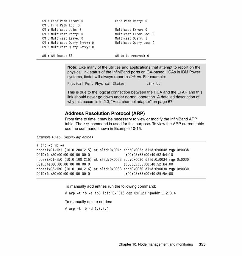
CM : Find Path Error: 0 Find Path Retry: 0CM : Find Path Loc: 0 CM : Multicast Join: 2 Multicast Error: 0CM : Multicast Retry: 0 Multicast Error Loc: 0CM : Multicast Leave: 0 Multicast Query: 1CM : Multicast Query Error: 0 Multicast Query Loc: 0CM : Multicast Query Retry: 0
AH : AH inuse: 57 AH to be removed: 0
Address Resolution Protocol (ARP)From time to time it may be necessary to view or modify the InfiniBand ARP table. The arp command is used for this purpose. To view the ARP current table use the command shown in Example 10-15.
Example 10-15 Display arp entries
# arp -t ib -anodeaix01-ib1 (10.0.200.215) at slid:0x004c sqp:0x003b dlid:0x0048 rqp:0x003b DGID:fe:80:00:00:00:00:00:0 a:00:02:55:00:40:52:b4:10nodeaix01-ib0 (10.0.100.215) at slid:0x0038 sqp:0x0030 dlid:0x0034 rqp:0x0030 DGID:fe:80:00:00:00:00:00:0 a:00:02:55:00:40:52:b4:00nodeaix02-ib0 (10.0.100.216) at slid:0x0038 sqp:0x0030 dlid:0x0030 rqp:0x0030 DGID:fe:80:00:00:00:00:00:0 a:00:02:55:00:40:85:9e:00
To manually add entries run the following command:
# arp -t ib -s ib0 ldid 0xFE12 dqp 0xF123 ipaddr 1.2.3.4
To manually delete entries:
# arp -t ib -d 1.2.3.4
Note: Like many of the utilities and applications that attempt to report on the physical link status of the InfiniBand ports on GX-based HCAs in IBM Power systems, ibstat will always report a link up. For example:
Physical Port Physical State: Link Up
This is due to the logical connection between the HCA and the LPAR and this link should never go down under normal operation. A detailed description of why this occurs is in 2.3, “Host channel adapter” on page 67.
Chapter 10. Node management and monitoring 355
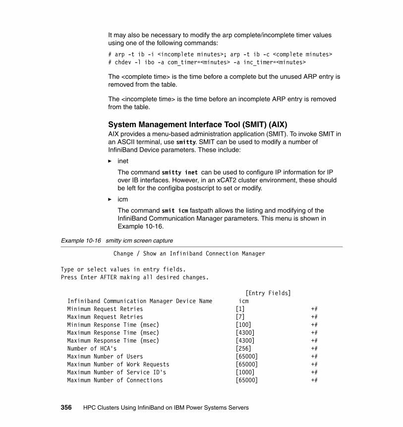
It may also be necessary to modify the arp complete/incomplete timer values using one of the following commands:
# arp -t ib -i <incomplete minutes>; arp -t ib -c <complete minutes># chdev -l ibo -a com_timer=<minutes> -a inc_timer=<minutes>
The <complete time> is the time before a complete but the unused ARP entry is removed from the table.
The <incomplete time> is the time before an incomplete ARP entry is removed from the table.
System Management Interface Tool (SMIT) (AIX)AIX provides a menu-based administration application (SMIT). To invoke SMIT in an ASCII terminal, use smitty. SMIT can be used to modify a number of InfiniBand Device parameters. These include:
� inet
The command smitty inet can be used to configure IP information for IP over IB interfaces. However, in an xCAT2 cluster environment, these should be left for the configiba postscript to set or modify.
� icm
The command smit icm fastpath allows the listing and modifying of the InfiniBand Communication Manager parameters. This menu is shown in Example 10-16.
Example 10-16 smitty icm screen capture
Change / Show an Infiniband Connection Manager
Type or select values in entry fields.Press Enter AFTER making all desired changes.
[Entry Fields] Infiniband Communication Manager Device Name icm Minimum Request Retries [1] +# Maximum Request Retries [7] +# Minimum Response Time (msec) [100] +# Maximum Response Time (msec) [4300] +# Maximum Response Time (msec) [4300] +#Number of HCA's [256] +#
Maximum Number of Users [65000] +# Maximum Number of Work Requests [65000] +# Maximum Number of Service ID's [1000] +# Maximum Number of Connections [65000] +#
356 HPC Clusters Using InfiniBand on IBM Power Systems Servers
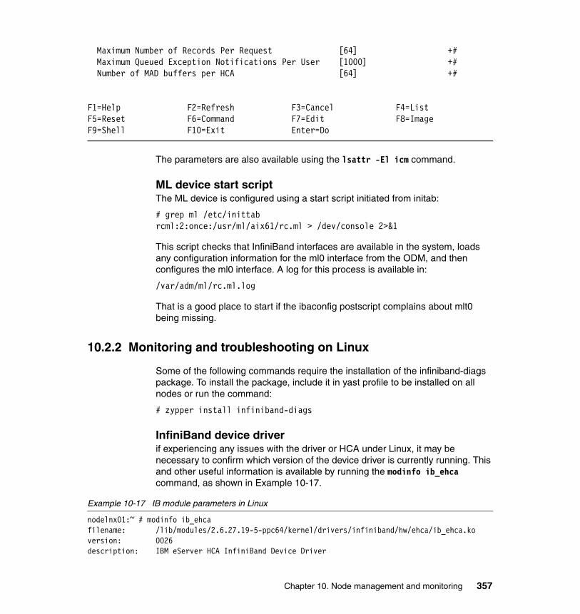
Maximum Number of Records Per Request [64] +# Maximum Queued Exception Notifications Per User [1000] +# Number of MAD buffers per HCA [64] +#
F1=Help F2=Refresh F3=Cancel F4=ListF5=Reset F6=Command F7=Edit F8=ImageF9=Shell F10=Exit Enter=Do
The parameters are also available using the lsattr -El icm command.
ML device start scriptThe ML device is configured using a start script initiated from initab:
# grep ml /etc/inittabrcml:2:once:/usr/ml/aix61/rc.ml > /dev/console 2>&1
This script checks that InfiniBand interfaces are available in the system, loads any configuration information for the ml0 interface from the ODM, and then configures the ml0 interface. A log for this process is available in:
/var/adm/ml/rc.ml.log
That is a good place to start if the ibaconfig postscript complains about mlt0 being missing.
10.2.2 Monitoring and troubleshooting on Linux
Some of the following commands require the installation of the infiniband-diags package. To install the package, include it in yast profile to be installed on all nodes or run the command:
# zypper install infiniband-diags
InfiniBand device driverif experiencing any issues with the driver or HCA under Linux, it may be necessary to confirm which version of the device driver is currently running. This and other useful information is available by running the modinfo ib_ehca command, as shown in Example 10-17.
Example 10-17 IB module parameters in Linux
nodelnx01:~ # modinfo ib_ehcafilename: /lib/modules/2.6.27.19-5-ppc64/kernel/drivers/infiniband/hw/ehca/ib_ehca.koversion: 0026description: IBM eServer HCA InfiniBand Device Driver
Chapter 10. Node management and monitoring 357
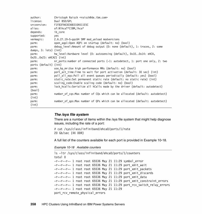
author: Christoph Raisch <[email protected]>license: Dual BSD/GPLsrcversion: F1F83FA63036B310A511E5Calias: of:NlhcaT*CIBM,lhca*depends: ib_coresupported: yesvermagic: 2.6.27.19-5-ppc64 SMP mod_unload modversionsparm: open_aqp1:Open AQP1 on startup (default: no) (bool)parm: debug_level:Amount of debug output (0: none (default), 1: traces, 2: some dumps, 3: lots) (int)parm: hw_level:Hardware level (0: autosensing (default), 0x10..0x14: eHCA, 0x20..0x23: eHCA2) (int)parm: nr_ports:number of connected ports (-1: autodetect, 1: port one only, 2: two ports (default) (int)parm: use_hp_mr:Use high performance MRs (default: no) (bool)parm: port_act_time:Time to wait for port activation (default: 30 sec) (int)parm: poll_all_eqs:Poll all event queues periodically (default: yes) (bool)parm: static_rate:Set permanent static rate (default: no static rate) (int)parm: scaling_code:Enable scaling code (default: no) (bool)parm: lock_hcalls:Serialize all hCalls made by the driver (default: autodetect) (bool)parm: number_of_cqs:Max number of CQs which can be allocated (default: autodetect) (int)parm: number_of_qps:Max number of QPs which can be allocated (default: autodetect) (int)
The /sys file system There are a number of items within the /sys file system that might help diagnose issues, including the rate of a port:
# cat /sys/class/infiniband/ehca0/ports/1/rate20 Gb/sec (4X DDR)
A full list of the counters available for each port is provided in Example 10-18.
Example 10-18 Available counters
ls -ltr /sys/class/infiniband/ehca0/ports/1/counterstotal 0-r--r--r-- 1 root root 65536 May 21 11:29 symbol_error-r--r--r-- 1 root root 65536 May 21 11:29 port_xmit_wait-r--r--r-- 1 root root 65536 May 21 11:29 port_xmit_packets-r--r--r-- 1 root root 65536 May 21 11:29 port_xmit_discards-r--r--r-- 1 root root 65536 May 21 11:29 port_xmit_data-r--r--r-- 1 root root 65536 May 21 11:29 port_xmit_constraint_errors-r--r--r-- 1 root root 65536 May 21 11:29 port_rcv_switch_relay_errors-r--r--r-- 1 root root 65536 May 21 11:29 port_rcv_remote_physical_errors
358 HPC Clusters Using InfiniBand on IBM Power Systems Servers
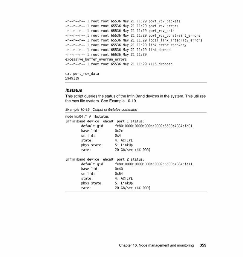
-r--r--r-- 1 root root 65536 May 21 11:29 port_rcv_packets-r--r--r-- 1 root root 65536 May 21 11:29 port_rcv_errors-r--r--r-- 1 root root 65536 May 21 11:29 port_rcv_data-r--r--r-- 1 root root 65536 May 21 11:29 port_rcv_constraint_errors-r--r--r-- 1 root root 65536 May 21 11:29 local_link_integrity_errors-r--r--r-- 1 root root 65536 May 21 11:29 link_error_recovery-r--r--r-- 1 root root 65536 May 21 11:29 link_downed-r--r--r-- 1 root root 65536 May 21 11:29 excessive_buffer_overrun_errors-r--r--r-- 1 root root 65536 May 21 11:29 VL15_dropped
cat port_rcv_data2949119
ibstatusThis script queries the status of the InfiniBand devices in the system. This utilizes the /sys file system. See Example 10-19.
Example 10-19 Output of ibstatus command
nodelnx04:~ # ibstatusInfiniband device 'ehca0' port 1 status: default gid: fe80:0000:0000:000a:0002:5500:4084:fa01 base lid: 0x2c sm lid: 0x4 state: 4: ACTIVE phys state: 5: LinkUp rate: 20 Gb/sec (4X DDR)
Infiniband device 'ehca0' port 2 status: default gid: fe80:0000:0000:000a:0002:5500:4084:fa11 base lid: 0x40 sm lid: 0x54 state: 4: ACTIVE phys state: 5: LinkUp rate: 20 Gb/sec (4X DDR)
Chapter 10. Node management and monitoring 359
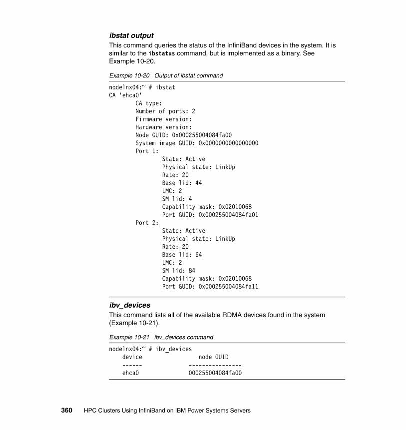
ibstat outputThis command queries the status of the InfiniBand devices in the system. It is similar to the ibstatus command, but is implemented as a binary. See Example 10-20.
Example 10-20 Output of ibstat command
nodelnx04:~ # ibstatCA 'ehca0' CA type: Number of ports: 2 Firmware version: Hardware version: Node GUID: 0x000255004084fa00 System image GUID: 0x0000000000000000 Port 1: State: Active Physical state: LinkUp Rate: 20 Base lid: 44 LMC: 2 SM lid: 4 Capability mask: 0x02010068 Port GUID: 0x000255004084fa01 Port 2: State: Active Physical state: LinkUp Rate: 20 Base lid: 64 LMC: 2 SM lid: 84 Capability mask: 0x02010068 Port GUID: 0x000255004084fa11
ibv_devices This command lists all of the available RDMA devices found in the system (Example 10-21).
Example 10-21 ibv_devices command
nodelnx04:~ # ibv_devices device node GUID ------ ---------------- ehca0 000255004084fa00
360 HPC Clusters Using InfiniBand on IBM Power Systems Servers

ibv_devinfoThis command provides more detail than ibv_devices on available RDMA devices found in the system (Example 10-22).
Example 10-22 ibv_devinfo command
nodelnx04:~ # ibv_devinfo -vhca_id: ehca0 node_guid: 0002:5500:4084:fa00 sys_image_guid: 0000:0000:0000:0000 vendor_id: 0x5076 vendor_part_id: 1 hw_ver: 0x2000021 phys_port_cnt: 2 max_mr_size: 0xc0000000 page_size_cap: 0x11000 max_qp: 16380 max_qp_wr: 32768 device_cap_flags: 0x00005800 max_sge: 252 max_sge_rd: 0 max_cq: 16383 max_cqe: 2147483647 max_mr: 31744 max_pd: 2147483647 max_qp_rd_atom: 3 max_ee_rd_atom: 0 max_res_rd_atom: 32768 max_qp_init_rd_atom: 128 max_ee_init_rd_atom: 0 atomic_cap: ATOMIC_NONE (0) max_ee: 0 max_rdd: 0 max_mw: 31744 max_raw_ipv6_qp: 0 max_raw_ethy_qp: 0 max_mcast_grp: 32 max_mcast_qp_attach: 8 max_total_mcast_qp_attach: 256 max_ah: 2147483647 max_fmr: 31744 max_map_per_fmr: 0 max_srq: 16380 max_srq_wr: 32768 max_srq_sge: 3
Chapter 10. Node management and monitoring 361
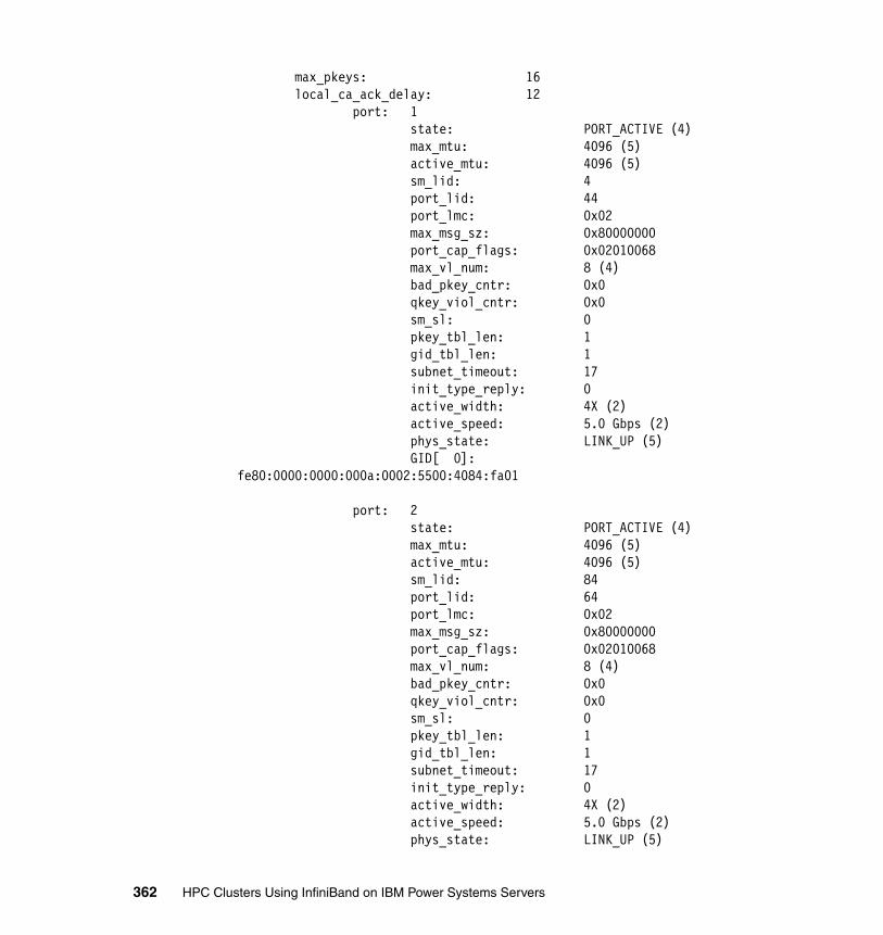
max_pkeys: 16 local_ca_ack_delay: 12 port: 1 state: PORT_ACTIVE (4) max_mtu: 4096 (5) active_mtu: 4096 (5) sm_lid: 4 port_lid: 44 port_lmc: 0x02 max_msg_sz: 0x80000000 port_cap_flags: 0x02010068 max_vl_num: 8 (4) bad_pkey_cntr: 0x0 qkey_viol_cntr: 0x0 sm_sl: 0 pkey_tbl_len: 1 gid_tbl_len: 1 subnet_timeout: 17 init_type_reply: 0 active_width: 4X (2) active_speed: 5.0 Gbps (2) phys_state: LINK_UP (5) GID[ 0]: fe80:0000:0000:000a:0002:5500:4084:fa01
port: 2 state: PORT_ACTIVE (4) max_mtu: 4096 (5) active_mtu: 4096 (5) sm_lid: 84 port_lid: 64 port_lmc: 0x02 max_msg_sz: 0x80000000 port_cap_flags: 0x02010068 max_vl_num: 8 (4) bad_pkey_cntr: 0x0 qkey_viol_cntr: 0x0 sm_sl: 0 pkey_tbl_len: 1 gid_tbl_len: 1 subnet_timeout: 17 init_type_reply: 0 active_width: 4X (2) active_speed: 5.0 Gbps (2) phys_state: LINK_UP (5)
362 HPC Clusters Using InfiniBand on IBM Power Systems Servers

GID[ 0]: fe80:0000:0000:000a:0002:5500:4084:fa11
The openibd start scriptThis script is used to start and stop the OFED service on a Linux node and can also provide useful information if run with the status flag. Details are provided in Example 10-23.
Example 10-23 Output of openibd command
/etc/init.d/openibd status
HCA driver loaded
Configured IPoIB devices:ib0 ib1
Currently active IPoIB devices:ib0ib1
The following OFED modules are loaded:
rdma_ucm ib_srp rdma_cm ib_addr ib_ipoib ib_ehca mlx4_core mlx4_ib mlx4_en ib_mthca ib_uverbs ib_umad ib_sa ib_cm ib_mad ib_core iw_cxgb3
Chapter 10. Node management and monitoring 363
10.2.3 Another monitoring tool: Ganglia
Ganglia is a scalable distributed monitoring system specifically designed with high-performance clusters in mind. Its best feature is its ability to provide an overview of certain characteristics within all nodes of a cluster, for example, memory, CPU, and network utilization. This high-level overview is something that is critical within an InfiniBand cluster, as patterns may emerge that indicate a problem or performance issue. For further details on Ganglia see:
http://www.ibm.com/developerworks/wikis/display/WikiPtype/ganglia
Or go to the Ganglia home page:
http://ganglia.info
10.2.4 Troubleshooting tools from HPC stack
In this section we discuss troubleshooting tools from the HPC stack.
LoadLevellerFor LoadLeveller:
� llstatus
The -a and -l options of llstatus display the port number for all available InfiniBand adapters visible to LoadLeveller.
The llstatus command will not show port information for non-IB adapters.
The information format is:
adapter_name(network_type, interface_name, interface_address, multilink_address, switch_node_number or adapter_logical_id, available_adapter_windows/total_adapter_windows, unused rCxt blocks/total rCxt blocks, adapter_fabric_connectivity, adapter_state[,adapter mcm id])
For example:
ib0(InfiniBand,c957f3ec12-ib0,10.0.1.60,,158487356,96/128,0/0 rCxt Blks,1,READY,1,MCM0)
� llq
The -l option for llq displays the port number of any infiniBand adapters in use.
� llsummary
The -l option for llsummary displays the port number of any InfiniBand adapters.
364 HPC Clusters Using InfiniBand on IBM Power Systems Servers
PEPE/POE installs a partition manager daemon that is required to run on every node for POE to leverage the InfiniBand infrastructure. It should be configured in /etc/services:
# grep pmv /etc/servicespmv5 6128/tcp # Version 5 partition manager
It should be running from inetd:
# the following line is the Version 5 POE Partition Manager Daemonpmv5 stream tcp6 nowait root /etc/pmdv5 pmdv5
It should be listening on port 6128 on all nodes:
# netstat -an|grep 6128tcp 0 0 *.6128 *.* LISTEN
10.2.5 Congestion in an InfiniBand Fabric
Congestion in an InfiniBand Fabric is usually caused by bottlenecks in the communication between two endpoints. The endpoints could be ports on a node, switch, or the fabric management server. For details see 9.3.4, “Recognizing congestion” on page 302, and 9.3.5, “Identifying sources of congestion” on page 305.
10.3 End-to-end startup/shutdown procedures
Below is an overview of the procedure to follow when starting up or shutting down a typical IBM Power System InfiniBand HPC cluster. It includes nodes, HPC stack, and fabric components. It assumes that the cluster in question is under the control of xCAT2.
10.3.1 End-to-end shutdown procedure
This procedure can be used to shut down all HPC and InfiniBand components:
1. Stop all client applications. The end result is that nothing should be using the InfiniBand interconnects for the cluster that you wish to shut down.
2. Shut down all IB-connected LPARs (for example, using xCAT2).
3. Power off all the CECs (for example, using xCAT2). This is required for GX+ IB HCAs only.
4. If required, power off frames. This depends on the reason for the shutdown.
Chapter 10. Node management and monitoring 365

5. Shut down all QLogic Fabric Managers.
6. If required, power off HMCs.
7. Power off SilverStorm 9000 Series Switch.
As these switches do not have a remote off or even a power switch, the only way to power them down is to:
– Pull all power connectors on the switches.– Shut down power to the rack in which they are installed.
At the end of this procedure you should still have your xCAT2 management server available, possibly with all HMCs still functioning.
10.3.2 End-to-end startup procedure
The startup procedure is
1. Power on SilverStorm 9000 Series Switches.
Do not proceed with the starting of the HSMs until all lights on the switches are green and solid.
2. Power on all HMCs.
If HMCs were powered off, power them on and wait for the login screen to appear.
3. Power on QLogic Fabric Managers.
Once all switches are fully started, power on the QLogic Fabric Manager servers.
4. Power on all IBM Power Frames.
Once the HMCs are booted and at the login prompt power on all IBM Power Frames.
5. Power on all CECs.
Check on the QLogic Fabric Manager that they are fully functional.
6. Power on all InfiniBand connected CECs.
7. Reset IB port stats.
8. Activate all lpars.
9. Retrain/IB stress/IB verify activities.
If required, retrain any failed ports. This can be resolved using the techniques described in Chapter 9, “Fabric management and monitoring” on page 283.
366 HPC Clusters Using InfiniBand on IBM Power Systems Servers

Part 5 Appendixes
Part 5
© Copyright IBM Corp. 2009. All rights reserved. 367

368 HPC Clusters Using InfiniBand on IBM Power Systems Servers
Appendix A. Advanced syslog-ng configuration
In an large environment, managing the data logged by all systems may be very difficult because there are several administrators that have different responsibilities and, as a consequence, they may be monitoring different events of the same servers.
Another challenge on a centralized logging system is to sort the data based on different criteria. In this section we briefly explain how to set up the syslog-ng to use a database as a backend and a Web interface for sorting the data.
Figure A-1 on page 370 depicts how the logging data flows:
1. The servers (syslog clients) are sending log information using the syslog protocol. Currently, most of the servers or devices are sending data using UDP port 514, which is clear text. Servers with syslog-ng installed can send the log information also using TCP port 514, which is more reliable. Also, syslog-ng can encrypt the information.
2. The syslog servers can receive information using both protocols (UDP or TCP).
3. All logs are sent to a MySQL database server using a database client.
4. The php-syslog-ng frontend queries the database for requested information based on the filters that the user (admin) defined.
A
© Copyright IBM Corp. 2009. All rights reserved. 369
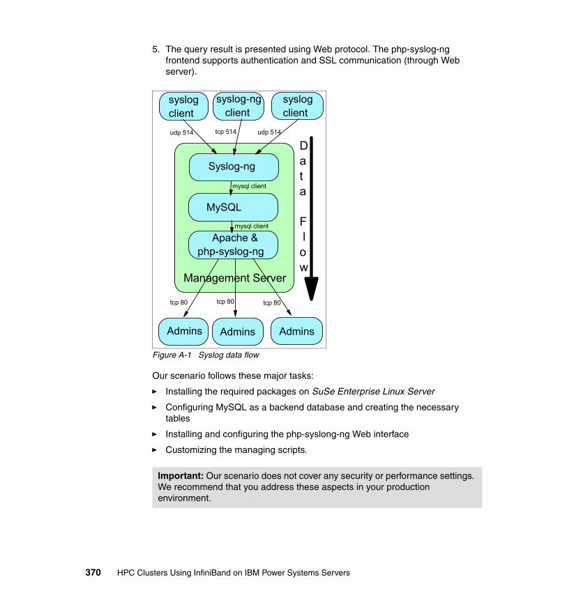
5. The query result is presented using Web protocol. The php-syslog-ng frontend supports authentication and SSL communication (through Web server).
Figure A-1 Syslog data flow
Our scenario follows these major tasks:
� Installing the required packages on SuSe Enterprise Linux Server
� Configuring MySQL as a backend database and creating the necessary tables
� Installing and configuring the php-syslong-ng Web interface
� Customizing the managing scripts.
Important: Our scenario does not cover any security or performance settings. We recommend that you address these aspects in your production environment.
Syslog-ng
syslog client
syslog-ng client
syslog client
MySQL
Apache &php-syslog-ng
Admins Admins Admins
Management Server
udp 514 tcp 514 udp 514
tcp 80 tcp 80 tcp 80
mysql client
mysql client
Data
F low
370 HPC Clusters Using InfiniBand on IBM Power Systems Servers
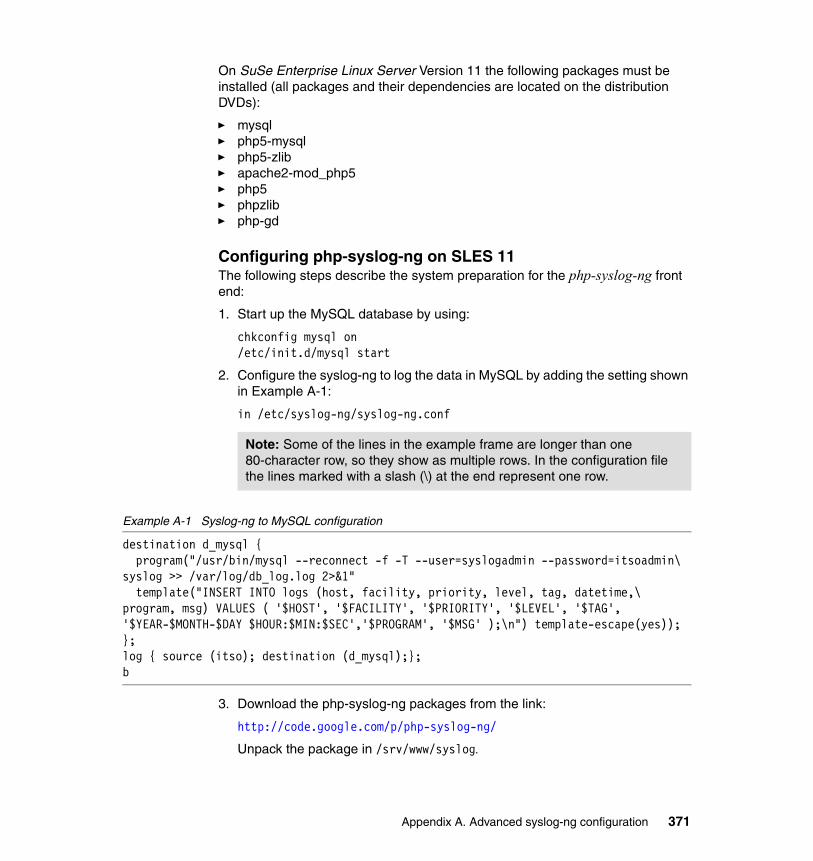
On SuSe Enterprise Linux Server Version 11 the following packages must be installed (all packages and their dependencies are located on the distribution DVDs):
� mysql� php5-mysql� php5-zlib� apache2-mod_php5� php5� phpzlib � php-gd
Configuring php-syslog-ng on SLES 11The following steps describe the system preparation for the php-syslog-ng front end:
1. Start up the MySQL database by using:
chkconfig mysql on /etc/init.d/mysql start
2. Configure the syslog-ng to log the data in MySQL by adding the setting shown in Example A-1:
in /etc/syslog-ng/syslog-ng.conf
Example A-1 Syslog-ng to MySQL configuration
destination d_mysql { program("/usr/bin/mysql --reconnect -f -T --user=syslogadmin --password=itsoadmin\ syslog >> /var/log/db_log.log 2>&1" template("INSERT INTO logs (host, facility, priority, level, tag, datetime,\ program, msg) VALUES ( '$HOST', '$FACILITY', '$PRIORITY', '$LEVEL', '$TAG', '$YEAR-$MONTH-$DAY $HOUR:$MIN:$SEC','$PROGRAM', '$MSG' );\n") template-escape(yes));};log { source (itso); destination (d_mysql);};b
3. Download the php-syslog-ng packages from the link:
http://code.google.com/p/php-syslog-ng/
Unpack the package in /srv/www/syslog.
Note: Some of the lines in the example frame are longer than one 80-character row, so they show as multiple rows. In the configuration file the lines marked with a slash (\) at the end represent one row.
Appendix A. Advanced syslog-ng configuration 371

4. Create an Apache configuration file for the directory /srv/www/syslog. The file is located in directory /etc/apache2/conf.d/syslog.conf and is shown in Example A-2. Reload the apache configuration by running:
/etc/init.d/apache2 reload
Example A-2 Apache configuration file for directory /srv/www/syslog
Alias /syslog "/srv/www/syslog"<Directory "srv/www/syslog"> Options -Indexes FollowSymLinks MultiViews AllowOverride None Order allow,deny Allow from all</Directory>
5. Make the following configuration files and directories writable:
mgtIBlnx:/srv/www/syslog/html # chmod -R 777 jpcachemgtIBlnx:/srv/www/syslog/html # chmod -R 777 config
6. For some performance increase, modify the file /etc/php5/apache2/php.ini with:
– memory_limit = 128M – max_execution_time = 300
Restart the apache daemon.
7. The following scripts need to be added in crontab as shown in Example A-3.
Example A-3 Logrotate and cache reload scripts in crontab
@daily php /srv/www/syslog/scripts/logrotate.php >> /var/log/syslog/logrotate.log@daily find /srv/www/syslog/html/jpcache/ -atime 1 -exec rm -f '{}' ';'*/5 * * * * php /srv/www/syslog/scripts/reloadcache.php >>\ /var/log/syslog/reloadcache.log
We chose to install the php-syslog-ng in a different path from the default. In this case the scripts must be modified to use the new path.
8. We choose not to use authentication, but for a production system we recommend setting it up.
372 HPC Clusters Using InfiniBand on IBM Power Systems Servers
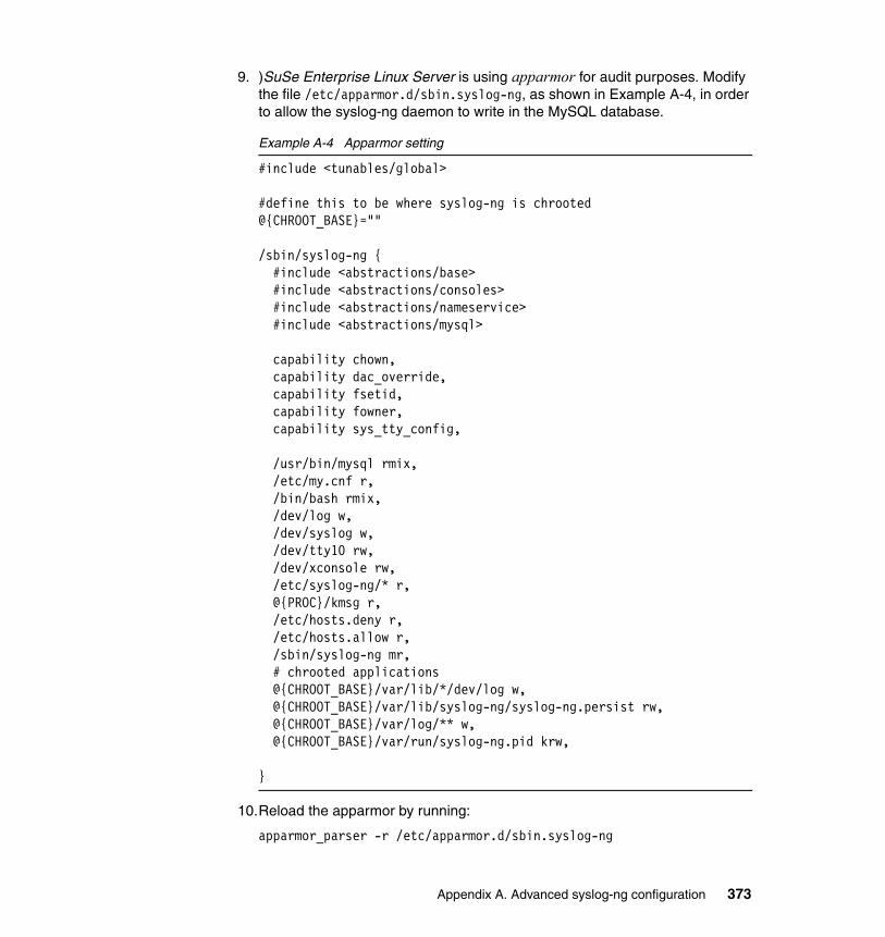
9. )SuSe Enterprise Linux Server is using apparmor for audit purposes. Modify the file /etc/apparmor.d/sbin.syslog-ng, as shown in Example A-4, in order to allow the syslog-ng daemon to write in the MySQL database.
Example A-4 Apparmor setting
#include <tunables/global>
#define this to be where syslog-ng is chrooted@{CHROOT_BASE}=""
/sbin/syslog-ng { #include <abstractions/base> #include <abstractions/consoles> #include <abstractions/nameservice> #include <abstractions/mysql>
capability chown, capability dac_override, capability fsetid, capability fowner, capability sys_tty_config,
/usr/bin/mysql rmix, /etc/my.cnf r, /bin/bash rmix, /dev/log w, /dev/syslog w, /dev/tty10 rw, /dev/xconsole rw, /etc/syslog-ng/* r, @{PROC}/kmsg r, /etc/hosts.deny r, /etc/hosts.allow r, /sbin/syslog-ng mr, # chrooted applications @{CHROOT_BASE}/var/lib/*/dev/log w, @{CHROOT_BASE}/var/lib/syslog-ng/syslog-ng.persist rw, @{CHROOT_BASE}/var/log/** w, @{CHROOT_BASE}/var/run/syslog-ng.pid krw,
}
10.Reload the apparmor by running:
apparmor_parser -r /etc/apparmor.d/sbin.syslog-ng
Appendix A. Advanced syslog-ng configuration 373

11.Connect to the Web server. In our case the link is:
http://192.168.100.111/syslog/html/
12.Follow the online wizard to configure the php-syslog-ng.
Note: The crontab scripts will rotate the tables and create a new table for each day. However, there is the table all_logs that contains all the information since the system was started. Other scripts must be developed in order to archive the information from the database.
374 HPC Clusters Using InfiniBand on IBM Power Systems Servers
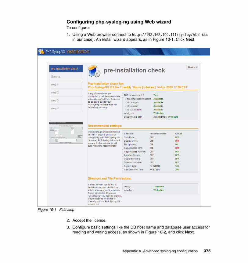
Configuring php-syslog-ng using Web wizard To configure:
1. Using a Web browser connect to http://192.168.100.111/syslog/html (as in our case). An install wizard appears, as in Figure 10-1. Click Next.
Figure 10-1 First step
2. Accept the license.
3. Configure basic settings like the DB host name and database user access for reading and writing access, as shown in Figure 10-2, and click Next.
Appendix A. Advanced syslog-ng configuration 375
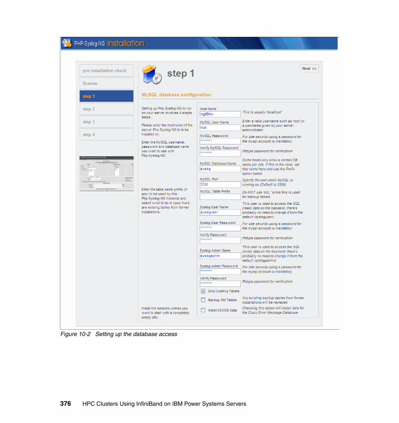
Figure 10-2 Setting up the database access
376 HPC Clusters Using InfiniBand on IBM Power Systems Servers
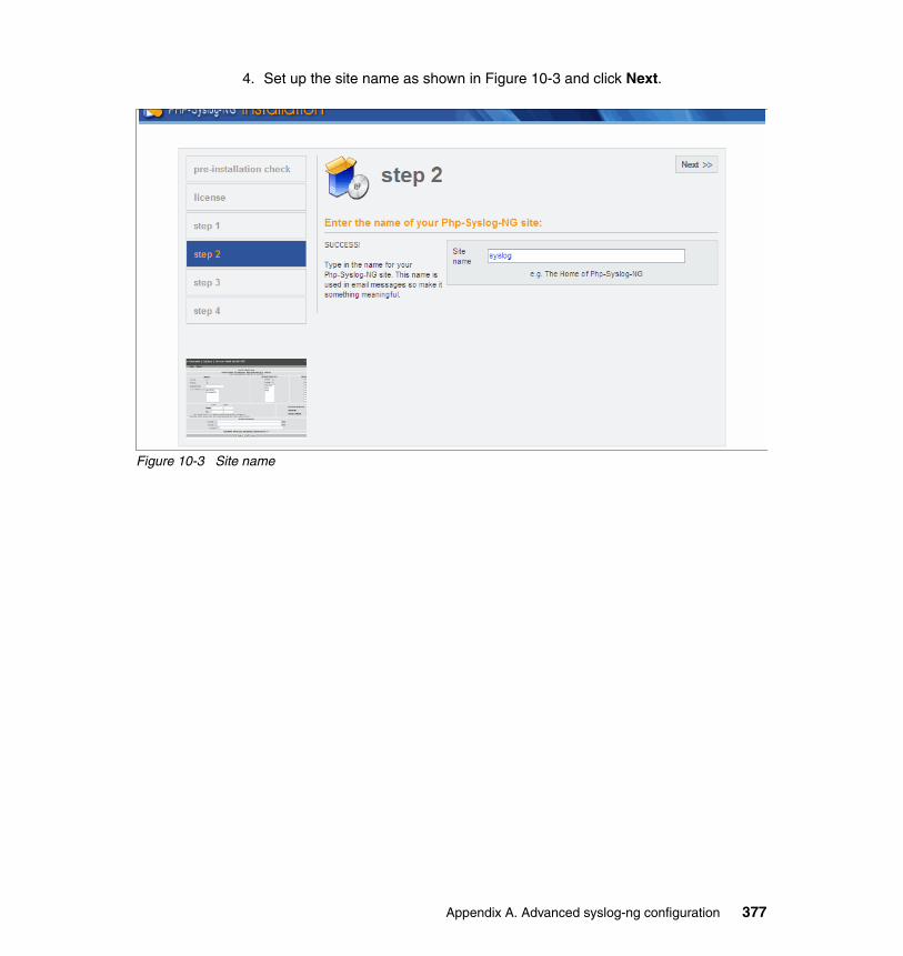
4. Set up the site name as shown in Figure 10-3 and click Next.
Figure 10-3 Site name
Appendix A. Advanced syslog-ng configuration 377
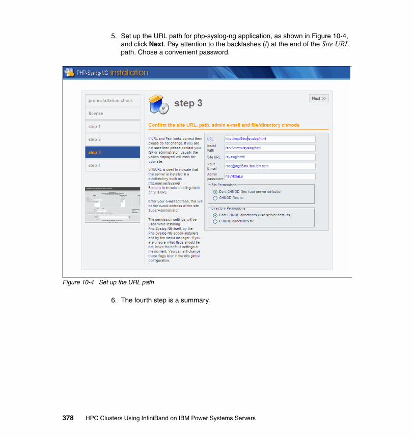
5. Set up the URL path for php-syslog-ng application, as shown in Figure 10-4, and click Next. Pay attention to the backlashes (/) at the end of the Site URL path. Chose a convenient password.
Figure 10-4 Set up the URL path
6. The fourth step is a summary.
378 HPC Clusters Using InfiniBand on IBM Power Systems Servers
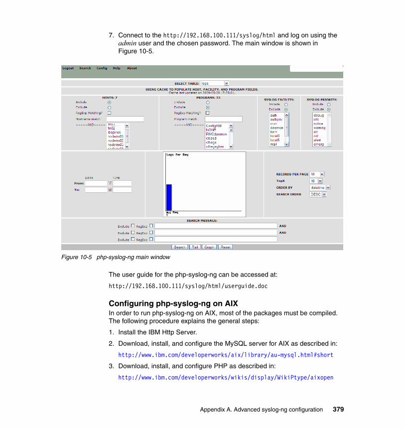
7. Connect to the http://192.168.100.111/syslog/html and log on using the admin user and the chosen password. The main window is shown in Figure 10-5.
Figure 10-5 php-syslog-ng main window
The user guide for the php-syslog-ng can be accessed at:
http://192.168.100.111/syslog/html/userguide.doc
Configuring php-syslog-ng on AIXIn order to run php-syslog-ng on AIX, most of the packages must be compiled. The following procedure explains the general steps:
1. Install the IBM Http Server.
2. Download, install, and configure the MySQL server for AIX as described in:
http://www.ibm.com/developerworks/aix/library/au-mysql.html#short
3. Download, install, and configure PHP as described in:
http://www.ibm.com/developerworks/wikis/display/WikiPtype/aixopen
Appendix A. Advanced syslog-ng configuration 379

4. Install bash, as the scripts are written in bash.
5. Install the scripts in crontab, as shown in Example A-3 on page 372
6. Run the wizard as described in “Configuring php-syslog-ng using Web wizard” on page 375
Several considerations Consider the following:
� Syslog-ng can work with other databases like DB2 or PostgreSQL, even on different systems.
� The database will grow in time. Proper management for limiting the database size is strongly recommended.
� The front-end php-syslog-ng is a multi-user system, each with different access policies.
380 HPC Clusters Using InfiniBand on IBM Power Systems Servers
Appendix B. Fabric port counters
This appendix provides a more detailed description of the port counters.
B
© Copyright IBM Corp. 2009. All rights reserved. 381
Port counter errors
This section explains the switch port errors in more detail by type. These should be checked on a daily basis in addition to syslog (compute nodes and QLogic Fabric Manager), errpt, and Service Focal Point on the HMC. The thresholds provided here are based on the recommendation in 9.3.2, “Link port counters” on page 297.
Link integrity errors
This type of error indicates an error on the local link. A bad cable is an example of a self-contained link problem. These errors could also be caused by an external event like a power outage or a user-initiated reboot.
� LinkDownedCounter
The link failed to retrain and connectivity was lost. This could also be a result of an outside initiated event like:
– Power cycle on CEC– Checkstop on CEC– Cable pull or reseat– Reseat of leaf– Service focal point event on the HMC– Power event on CEC– Power event on switch– Disabled link
– Performance impact: Any traffic communicating over this link will be impacted. It will also impact the application if the link is required for peak performance.
– Recommended threshold (1 hour): 2.
– Recommended threshold (24 hours): 3.
– The 8-bit counter will max out at 255 errors.
382 HPC Clusters Using InfiniBand on IBM Power Systems Servers

� LinkErrorRecoveryCounter
This error indicates that a link is experiencing an above-average amount of errors and initiated and completed a retrain action. This error could also appear on the GX+/GX++ HCA port during a user-initiated retrain or during CEC reboots (not LPAR reboots).
– Performance impact: Any traffic communicating over this link will be impacted. It will also impact the application if the link is required for peak performance.
– Recommended threshold (1 hour): 2.
– Recommended threshold (24 hours): 3.
– The 8-bit counter will max out at 255 errors.
� LocalLinkIntegrityErrors
The number of physical errors on the link exceeded the threshold. This could also be a result of an outside-initiated event like:
– Power cycle on CEC– Checkstop on CEC– Cable pull or reseat– Reseat of leaf– Service focal point event on the HMC– Power event on CEC– Power event on switch– Disabled link
Note:
– Performance impact: Any traffic communicating over this link will be impacted. It will also impact the application if the link is required for peak performance.
– Recommended threshold (1 hour): 2.
– Recommended threshold (24 hours): 3.
– The 4-bit counter will max out at 15 errors.
� ExcessiveBufferOverrunErrors
This error indicates an SM configuration error or poor link quality.
– Performance impact: Any traffic communicating over this link will be impacted.
– Recommended threshold (1 hour): 2.
– Recommended threshold (24 hours): 3.
– The 4-bit counter will max out at 15 errors.
Appendix B. Fabric port counters 383
� PortRcvErrors
Packets with errors were received. These port counters increment differently on the GX+/GX++ HCA and the switch. If the error does not fail into one of the other port counters, it will be a PortRcvError on the switch. The GX+/GX++ HCA can report it by itself, but it will always be incremented if one of those other errors occurs:
– Local physical errors– SymbolErrors– ExcessiveBufferOverrunErrors– PortRcvPhysicalRemoteErrors
Note:
– Recommended threshold (1 hour): 2.– Recommended threshold (24 hours): 10.– The 16-bit counter will max out at 65535 errors.
� SymbolErrorCounter
The SymbolErrorCounter is the most basic and common indicator of errors on a link. It indicates that an invalid combination of bits was received. While it is possible to get other link integrity errors on a link without SymbolErrors, this is not typical.
– Recommended threshold (1 hour): 2.– Recommended threshold (24 hours): 10.– The 16-bit counter will max out at 65535 errors.
Remote link integrity errors
The errors are:
� PortRcvRemotePhysicalErrors
This error indicates an issue caused by a remote link.
– Recommended threshold (1 hour): 4.– Recommended threshold (24 hours): 100.– The 4-bit counter will max out at 15 errors.
� PortXmitDiscards:
Total number of outbound packets discarded by the port due to the port state of down or due to congestion.
– Recommended threshold (1 hour): 4.– Recommended threshold (24 hours): 100.– The 4-bit counter will max out at 15 errors.
384 HPC Clusters Using InfiniBand on IBM Power Systems Servers
Security errors
These do not apply to IFS code 4.3 and earlier. Therefore, a properly configured cluster at those levels should never experience a security error.
� PortXimitConstraintErrors
– Recommended threshold (1 hour): 1.– Recommended threshold (24 hours): 1.– The 8-bit counter will max out at 255 errors.
� PortRcvConstraintErrors
– Recommended threshold (1 hour): 1.– Recommended threshold (24 hours): 1.– The 8-bit counter will max out at 255 errors.
Other errors
These errors fall outside of the typical link errors. See the definitions below for more information.
� VL15Dropped
VL15 is used by the subnet manager for its queries and the associated responses. It is common for some of these packets to be dropped during the discovery sweep. Unless otherwise directed by the service, ignore this counter.
– Recommended threshold (1 hour): N/A.– Recommended threshold (24 hours): N/A.– The 16-bit counter will max out at 65535 errors.
� PortRcvSwitchRelayErrors
There is a switch chip bug that causes this counter to increment at incorrect times. Therefore, ignore it.
– Recommended threshold (1 hour): N/A.– Recommended threshold (24 hours): N/A.– The 4-bit counter will max out at 15 errors.
Appendix B. Fabric port counters 385

386 HPC Clusters Using InfiniBand on IBM Power Systems Servers
Appendix C. Fabric Management scripts
This appendix provides sample scripts referenced in Chapter 9, “Fabric management and monitoring” on page 283, to set up and perform basic healthcheck functions.
C
© Copyright IBM Corp. 2009. All rights reserved. 387

Introduction
This appendix provides the following scripts. They are listed in order of appearance in Chapter 9, “Fabric management and monitoring” on page 283.
� clearerrors� retrain � getallerrors� healthcheck� configports
The scripts use the following directory format. Change and modify paths as needed.
/root/fmtools/health/root/fmtools/health/data/root/fmtools/health/Configfiles
Configuration fileExample C-1 is the configuration file (/root/fmtools/health/config) that lists variables referenced by the scripts in this appendix.
Example C-1 config file
# Configuration information#--------------------------------------------TOOLSDIR="/root/fmtools/health"DATADIR="$TOOLSDIR/data"ERRFILE="allerrs"CLEARFILE="$DATADIR/lastclear"CONFIGFILES="$TOOLSDIR/Configfiles"UTILDIR="/usr/local/iview/util"QBIN="/sbin"
ANALYSISDIR="/var/opt/iba/analysis"ANALYSISBASE="$ANALYSISDIR/baseline"ANALYSISLOG="$ANALYSISDIR/all_analysis.errlog"IBAMON="$CONFIGFILES/iba_mon.conf"
FF_CFG="/etc/sysconfig/fastfabric.conf"PORTSF="/etc/sysconfig/iba/ports"CHASSISF="/etc/sysconfig/iba/chassis"
# Modify swpat as the filter variable for matching switch devices only. It is# based on how you set the ibNodeDesc in the switches. The only wildcard is# allowed at the end of the pattern.# The default is "SilverStorm*"swpat="ib*"
# Get switch nodepat info from fastfabric.conf (FF_CFG)
388 HPC Clusters Using InfiniBand on IBM Power Systems Servers
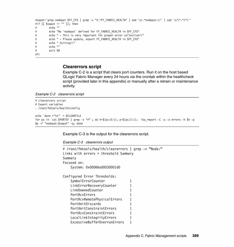
#swpat=`grep nodepat $FF_CFG | grep -v "#.*FF_FABRIC_HEALTH" | sed 's/.*nodepat://' | sed 's/\*.*/*/'`#if [[ $swpat == "" ]]; then# echo ""# echo "No 'nodepat' defined for FF_FABRIC_HEALTH in $FF_CFG"# echo " - This is very important for proper error collection!!"# echo " - Please update, export FF_FABRIC_HEALTH in $FF_CFG"# echo " Exiting!!"# echo ""# exit 99#fi
Clearerrors scriptExample C-2 is a script that clears port counters. Run it on the host based QLogic Fabric Manager every 24 hours via the crontab within the healthcheck script (provided later in this appendix) or manually after a retrain or maintenance activity.
Example C-2 clearerrors script
# clearerrors script# Export variables. /root/fmtools/health/config
echo `date +"%s"` > $CLEARFILEfor ps in `cat $PORTSF | grep -v "#"`; do h=${ps:0:1}; p=${ps:2:1}; iba_report -C -a -o errors -h $h -p $p -F "nodepat:$swpat" -q; done
Example C-3 is the output for the clearerrors script.
Example C-3 clearerrors output
# /root/fmtools/health/clearerrors | grep -v “Node:”Links with errors > threshold SummarySummaryFocused on: System: 0x00066a00030001d0
Configured Error Thresholds: SymbolErrorCounter 1 LinkErrorRecoveryCounter 1 LinkDownedCounter 1 PortRcvErrors 1 PortRcvRemotePhysicalErrors 1 PortXmitDiscards 1 PortXmitConstraintErrors 1 PortRcvConstraintErrors 1 LocalLinkIntegrityErrors 1 ExcessiveBufferOverrunErrors 1
Appendix C. Fabric Management scripts 389
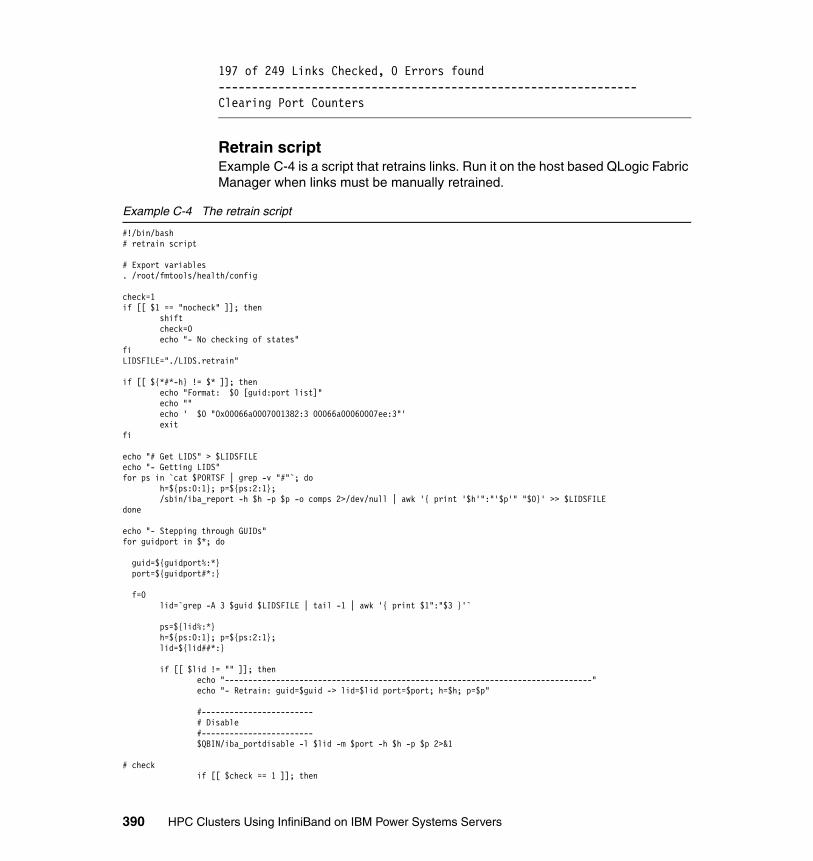
197 of 249 Links Checked, 0 Errors found---------------------------------------------------------------Clearing Port Counters
Retrain scriptExample C-4 is a script that retrains links. Run it on the host based QLogic Fabric Manager when links must be manually retrained.
Example C-4 The retrain script
#!/bin/bash# retrain script
# Export variables. /root/fmtools/health/config
check=1if [[ $1 == "nocheck" ]]; then shift check=0 echo "- No checking of states"fiLIDSFILE="./LIDS.retrain"
if [[ ${*#*-h} != $* ]]; then echo "Format: $0 [guid:port list]" echo "" echo ' $0 "0x00066a0007001382:3 00066a00060007ee:3"' exitfi
echo "# Get LIDS" > $LIDSFILEecho "- Getting LIDS"for ps in `cat $PORTSF | grep -v "#"`; do h=${ps:0:1}; p=${ps:2:1}; /sbin/iba_report -h $h -p $p -o comps 2>/dev/null | awk '{ print '$h'":"'$p'" "$0}' >> $LIDSFILEdone
echo "- Stepping through GUIDs"for guidport in $*; do
guid=${guidport%:*} port=${guidport#*:}
f=0 lid=`grep -A 3 $guid $LIDSFILE | tail -1 | awk '{ print $1":"$3 }'`
ps=${lid%:*} h=${ps:0:1}; p=${ps:2:1}; lid=${lid##*:}
if [[ $lid != "" ]]; then echo "-------------------------------------------------------------------------------" echo "- Retrain: guid=$guid -> lid=$lid port=$port; h=$h; p=$p"
#------------------------ # Disable #------------------------ $QBIN/iba_portdisable -l $lid -m $port -h $h -p $p 2>&1
# check if [[ $check == 1 ]]; then
390 HPC Clusters Using InfiniBand on IBM Power Systems Servers
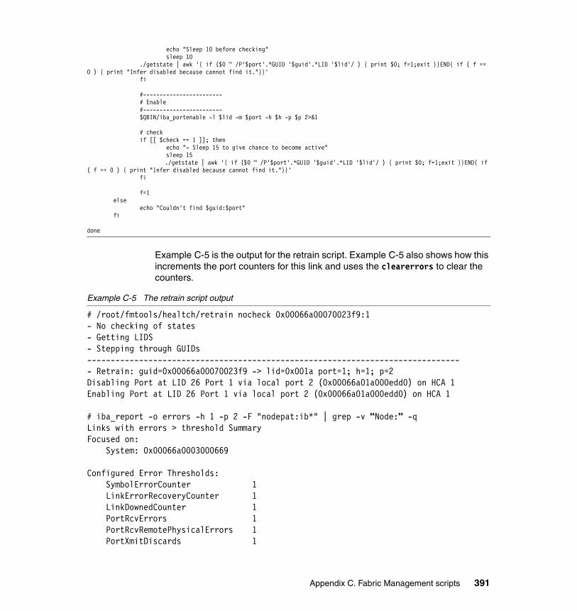
echo "Sleep 10 before checking" sleep 10 ./getstate | awk '{ if ($0 ~ /P'$port'.*GUID '$guid'.*LID '$lid'/ ) { print $0; f=1;exit }}END{ if ( f == 0 ) { print "Infer disabled because cannot find it."}}' fi
#------------------------ # Enable #------------------------ $QBIN/iba_portenable -l $lid -m $port -h $h -p $p 2>&1
# check if [[ $check == 1 ]]; then echo "- Sleep 15 to give chance to become active" sleep 15 ./getstate | awk '{ if ($0 ~ /P'$port'.*GUID '$guid'.*LID '$lid'/ ) { print $0; f=1;exit }}END{ if ( f == 0 ) { print "Infer disabled because cannot find it."}}' fi
f=1 else echo "Couldn't find $guid:$port" fi
done
Example C-5 is the output for the retrain script. Example C-5 also shows how this increments the port counters for this link and uses the clearerrors to clear the counters.
Example C-5 The retrain script output
# /root/fmtools/healtch/retrain nocheck 0x00066a00070023f9:1- No checking of states- Getting LIDS- Stepping through GUIDs-------------------------------------------------------------------------------- Retrain: guid=0x00066a00070023f9 -> lid=0x001a port=1; h=1; p=2Disabling Port at LID 26 Port 1 via local port 2 (0x00066a01a000edd0) on HCA 1Enabling Port at LID 26 Port 1 via local port 2 (0x00066a01a000edd0) on HCA 1
# iba_report -o errors -h 1 -p 2 -F "nodepat:ib*" | grep -v “Node:” -qLinks with errors > threshold SummaryFocused on: System: 0x00066a0003000669
Configured Error Thresholds: SymbolErrorCounter 1 LinkErrorRecoveryCounter 1 LinkDownedCounter 1 PortRcvErrors 1 PortRcvRemotePhysicalErrors 1 PortXmitDiscards 1
Appendix C. Fabric Management scripts 391
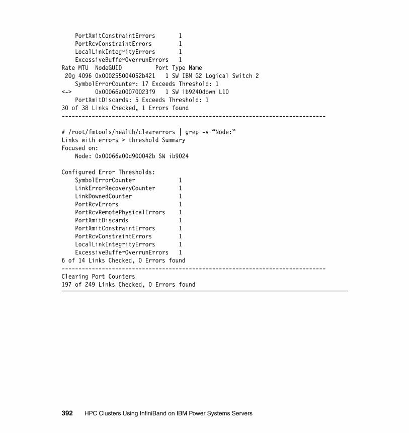
PortXmitConstraintErrors 1 PortRcvConstraintErrors 1 LocalLinkIntegrityErrors 1 ExcessiveBufferOverrunErrors 1Rate MTU NodeGUID Port Type Name 20g 4096 0x000255004052b421 1 SW IBM G2 Logical Switch 2 SymbolErrorCounter: 17 Exceeds Threshold: 1<-> 0x00066a00070023f9 1 SW ib9240down L10 PortXmitDiscards: 5 Exceeds Threshold: 130 of 38 Links Checked, 1 Errors found-------------------------------------------------------------------------------
# /root/fmtools/health/clearerrors | grep -v “Node:”Links with errors > threshold SummaryFocused on: Node: 0x00066a00d900042b SW ib9024
Configured Error Thresholds: SymbolErrorCounter 1 LinkErrorRecoveryCounter 1 LinkDownedCounter 1 PortRcvErrors 1 PortRcvRemotePhysicalErrors 1 PortXmitDiscards 1 PortXmitConstraintErrors 1 PortRcvConstraintErrors 1 LocalLinkIntegrityErrors 1 ExcessiveBufferOverrunErrors 16 of 14 Links Checked, 0 Errors found-------------------------------------------------------------------------------Clearing Port Counters197 of 249 Links Checked, 0 Errors found
392 HPC Clusters Using InfiniBand on IBM Power Systems Servers

Getallerrors scriptExample C-6 is a script that gets all errors (thresholds set to 1). Run it on the host based QLogic Fabric Manager on a hourly basis via the crontab. The output files can be used for additional debugging as the default thresholds are increased over time.
Example C-6 The getallerrors script
# getallerrors script (run getallerrors -d)# Export variables. /root/fmtools/health/config
# Name output fileDEFAULTNAME="allerrs"name="$1"
if [[ $name = "" ]]; then name="getallerrors.tmpout" noname=1else if [[ $name -eq '-d' ]]; then name="$DATADIR/$DEFAULTNAME."`date +"%Y%m%d_%H%M"` fi noname=0fi
echo `date`> $namefor h in 1 2; do for p in 1 2; do echo "h=$h; p=$p" >> $name; /sbin/iba_report -o errors -h $h -p $p -F "nodepat:$swpat" >> $name; done; done
count=`egrep "<->.*Leaf" $name | wc -l`list=`grep "<->.*Leaf" $name | awk '{l=NF-2; print $0" L"$l"-P"$3}' | sed 's/.*SW //' | sed 's/Leaf.*L/L/' | sed 's/,//g'`echo "-------------------"echo "$list"echo "Count=$count"echo "------------------" >> $nameecho "$list" >> $nameecho "Count = $count" >> $name
if [[ $noname = 1 ]]; then cat $namefi
Example C-7 is the output for the getallerrors script.
Example C-7 The getallerrors script output
# cat allerrs.20090530_1049h=1; p=1Links with errors > threshold SummaryFocused on: Node: 0x00066a00d900042b SW ib9024
Configured Error Thresholds: SymbolErrorCounter 1...
Appendix C. Fabric Management scripts 393
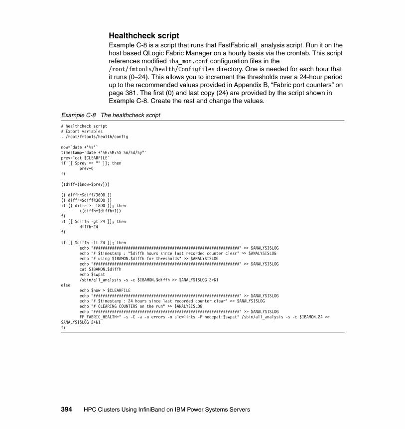
Healthcheck scriptExample C-8 is a script that runs that FastFabric all_analysis script. Run it on the host based QLogic Fabric Manager on a hourly basis via the crontab. This script references modified iba_mon.conf configuration files in the /root/fmtools/health/Configfiles directory. One is needed for each hour that it runs (0–24). This allows you to increment the thresholds over a 24-hour period up to the recommended values provided in Appendix B, “Fabric port counters” on page 381. The first (0) and last copy (24) are provided by the script shown in Example C-8. Create the rest and change the values.
Example C-8 The healthcheck script
# healthcheck script# Export variables. /root/fmtools/health/config
now=`date +"%s"`timestamp=`date +"%H:%M:%S %m/%d/%y"`prev=`cat $CLEARFILE`if [[ $prev == "" ]]; then prev=0fi
((diff=($now-$prev)))
(( diffh=$diff/3600 ))(( diffr=$diff%3600 ))if (( diffr >= 1800 )); then ((diffh=$diffh+1))fiif [[ $diffh -gt 24 ]]; then diffh=24fi
if [[ $diffh -lt 24 ]]; then echo "###############################################################" >> $ANALYSISLOG echo "# $timestamp : ~$diffh hours since last recorded counter clear" >> $ANALYSISLOG echo "# using $IBAMON.$diffh for thresholds" >> $ANALYSISLOG echo "###############################################################" >> $ANALYSISLOG cat $IBAMON.$diffh echo $swpat /sbin/all_analysis -s -c $IBAMON.$diffh >> $ANALYSISLOG 2>&1else echo $now > $CLEARFILE echo "###############################################################" >> $ANALYSISLOG echo "# $timestamp : 24 hours since last recorded counter clear" >> $ANALYSISLOG echo "# CLEARING COUNTERS on the run" >> $ANALYSISLOG echo "###############################################################" >> $ANALYSISLOG FF_FABRIC_HEALTH=" -s -C -a -o errors -o slowlinks -F nodepat:$swpat" /sbin/all_analysis -s -c $IBAMON.24 >> $ANALYSISLOG 2>&1fi
394 HPC Clusters Using InfiniBand on IBM Power Systems Servers

Example C-9 lists the additional iba_mon.conf.0 file.
Example C-9 iba_mon.conf .0 file
# cat /root/fmtools/health/Configfiles/iba_mon.conf.0# This file controls the iba_mon Port Counter monitoring Thresholds.# [ICS VERSION STRING: @(#) ./config/iba_mon.conf 4_2_0_2_1 [03/12/08 20:18]## Error Counters are specified in absolute number of errors over Interval.# All Data Movement thresholds are specified in terms of average data/second# over the monitoring interval.## Setting a threshold to 0 disables monitoring of the given counter## Output is generated when a threshold is exceeded.## Counters for which a non-zero threshold is specified will be cleared by# iba_mon and may impact any remote Performance Managers which are monitoring# the given Counter
Interval 10 # monitoring interval in seconds
SyslogFacility local6 # syslog facility code, or disable
# Normal Data MovementPortXmitData 0 # as MB/secondPortRcvData 0 # as MB/secondPortXmitPkts 0 # as packets/secondPortRcvPkts 0 # as packets/second
# Error CountersSymbolErrorCounter 3 # 10 per day in $diffh hoursLinkErrorRecoveryCounter 1 # 3 per day in $diffh hoursLinkDownedCounter 1 # 3 per day in $diffh hoursPortRcvErrors 3 # 10 per day in $diffh hoursPortRcvRemotePhysicalErrors 3 # 10 per day in $diffh hours#PortRcvSwitchRelayErrors 100 # known Anafa2 issue, incorrectly incrementsPortXmitDiscards 3 # 10 per day in $diffh hoursPortXmitConstraintErrors 3 # 10 per day in $diffh hoursPortRcvConstraintErrors 3 # 10 per day in $diffh hoursLocalLinkIntegrityErrors 1 # 3 per day in $diffh hoursExcessiveBufferOverrunErrors 1 # 3 per day in $diffh hoursVL15Dropped 0
Example C-10 lists the additional iba_mon.conf.24 file.
Example C-10 Additional iba_mon.conf.24.file
# This file controls the iba_mon Port Counter monitoring Thresholds.# [ICS VERSION STRING: @(#) ./config/iba_mon.conf 4_2_0_2_1 [03/12/08 20:18]## Error Counters are specified in absolute number of errors over Interval.# All Data Movement thresholds are specified in terms of average data/second# over the monitoring interval.## Setting a threshold to 0 disables monitoring of the given counter## Output is generated when a threshold is exceeded.## Counters for which a non-zero threshold is specified will be cleared by# iba_mon and may impact any remote Performance Managers which are monitoring# the given Counter
Interval 10 # monitoring interval in seconds
Appendix C. Fabric Management scripts 395
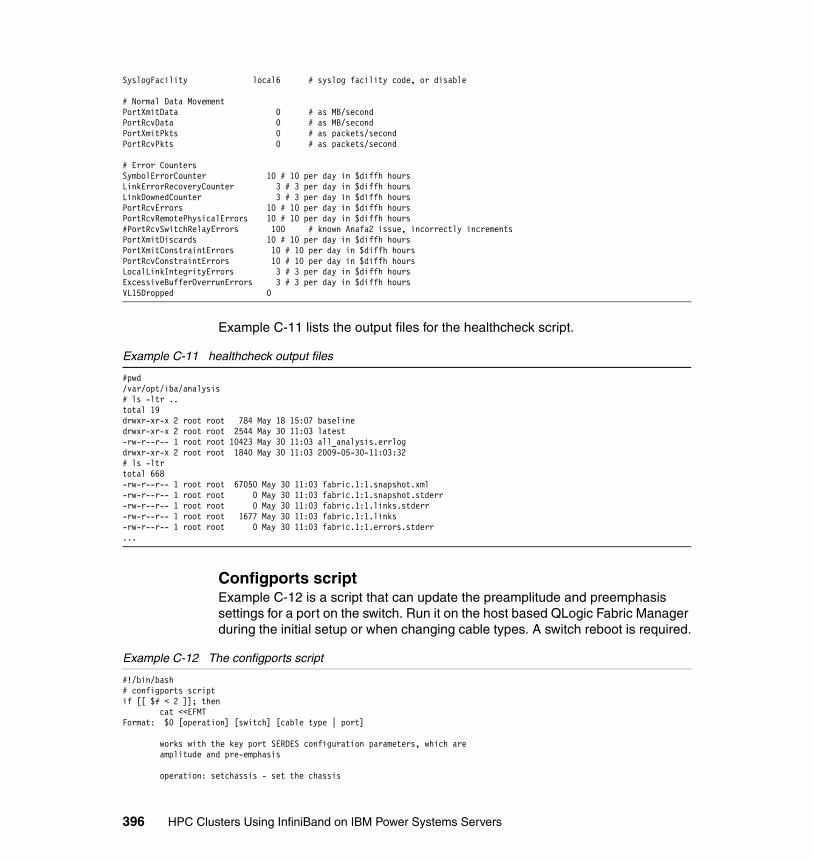
SyslogFacility local6 # syslog facility code, or disable
# Normal Data MovementPortXmitData 0 # as MB/secondPortRcvData 0 # as MB/secondPortXmitPkts 0 # as packets/secondPortRcvPkts 0 # as packets/second
# Error CountersSymbolErrorCounter 10 # 10 per day in $diffh hoursLinkErrorRecoveryCounter 3 # 3 per day in $diffh hoursLinkDownedCounter 3 # 3 per day in $diffh hoursPortRcvErrors 10 # 10 per day in $diffh hoursPortRcvRemotePhysicalErrors 10 # 10 per day in $diffh hours#PortRcvSwitchRelayErrors 100 # known Anafa2 issue, incorrectly incrementsPortXmitDiscards 10 # 10 per day in $diffh hoursPortXmitConstraintErrors 10 # 10 per day in $diffh hoursPortRcvConstraintErrors 10 # 10 per day in $diffh hoursLocalLinkIntegrityErrors 3 # 3 per day in $diffh hoursExcessiveBufferOverrunErrors 3 # 3 per day in $diffh hoursVL15Dropped 0
Example C-11 lists the output files for the healthcheck script.
Example C-11 healthcheck output files
#pwd/var/opt/iba/analysis# ls -ltr ..total 19drwxr-xr-x 2 root root 784 May 18 15:07 baselinedrwxr-xr-x 2 root root 2544 May 30 11:03 latest-rw-r--r-- 1 root root 10423 May 30 11:03 all_analysis.errlogdrwxr-xr-x 2 root root 1840 May 30 11:03 2009-05-30-11:03:32# ls -ltrtotal 668-rw-r--r-- 1 root root 67050 May 30 11:03 fabric.1:1.snapshot.xml-rw-r--r-- 1 root root 0 May 30 11:03 fabric.1:1.snapshot.stderr-rw-r--r-- 1 root root 0 May 30 11:03 fabric.1:1.links.stderr-rw-r--r-- 1 root root 1677 May 30 11:03 fabric.1:1.links-rw-r--r-- 1 root root 0 May 30 11:03 fabric.1:1.errors.stderr...
Configports scriptExample C-12 is a script that can update the preamplitude and preemphasis settings for a port on the switch. Run it on the host based QLogic Fabric Manager during the initial setup or when changing cable types. A switch reboot is required.
Example C-12 The configports script
#!/bin/bash# configports scriptif [[ $# < 2 ]]; then cat <<EFMTFormat: $0 [operation] [switch] [cable type | port]
works with the key port SERDES configuration parameters, which are amplitude and pre-emphasis
operation: setchassis - set the chassis
396 HPC Clusters Using InfiniBand on IBM Power Systems Servers

setport querychassis queryport
switch: all [space delimited list of switch addresses in quotes]
cable type: IHoptical IHcopper default default9024 - default settings for 9024 switches
port: port when setting or querying port; a space delimited list can be given within quotes
Query results will be organized by switch, and then by amplitude and then by pre-emphasis. If you query more than one port, it will execute the commands one port at a time on every switch listed.
Examples: # queries all ports on all chassis configports querychassis all | less
# set all ports on all switches to the amplitude and pre-emphasis # settings for copper IH cables. configports setchassis all IHcopper
# For switches 1 and 2, set leaf 5 port 4 and leaf 3 port 7 to # the default amplitude and pre-emphasis for a non-9024 switch configports setport "switch1 switch2" default "L05P04 L03P07"
Remember the FM server cables. These are quite often set to the default. So, a cluster with only IH copper cables could be set to IHcopper values, but the FM server cables would have to be set back to default.
So, if the FM servers are all connected to L12P12 and L11P12, and all of your other cables are IH copper cables, you would issue two commands:
configports setchassis all IHcopper configports setport all default "L11P12 L12P12"
# You might have to do this on separate FM servers, if the # /etc/sysconfig/iba/chassis file is not setup to get to all switches
*** DO NOT FORGET TO REBOOT for the settings to take effect ***EFMT
exit
fiop=$1switch=$2cabtype=$3port=$4if [[ $# < 4 ]];then port=$3fi
if [[ $switch == "all" ]]; then
excmd="/sbin/cmdall -C"
else
excmd="/sbin/cmdall -C -H \"$2\""
fi
Appendix C. Fabric Management scripts 397
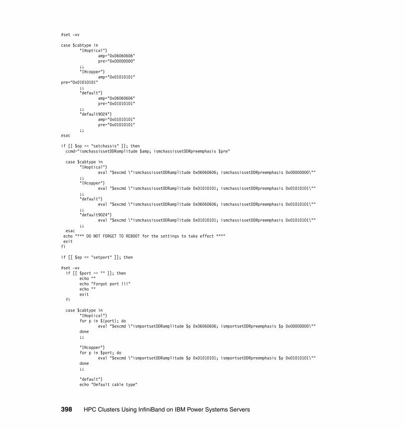
#set -xv
case $cabtype in "IHoptical") amp="0x06060606" pre="0x00000000" ;; "IHcopper") amp="0x01010101"pre="0x01010101" ;; "default") amp="0x06060606" pre="0x01010101" ;; "default9024") amp="0x01010101" pre="0x01010101" ;;esac
if [[ $op == "setchassis" ]]; then ccmd="ismchassissetDDRamplitude $amp; ismchassissetDDRpreemphasis $pre"
case $cabtype in "IHoptical") eval "$excmd \"ismchassissetDDRamplitude 0x06060606; ismchassissetDDRpreemphasis 0x00000000\"" ;; "IHcopper") eval "$excmd \"ismchassissetDDRamplitude 0x01010101; ismchassissetDDRpreemphasis 0x01010101\"" ;; "default") eval "$excmd \"ismchassissetDDRamplitude 0x06060606; ismchassissetDDRpreemphasis 0x01010101\"" ;; "default9024") eval "$excmd \"ismchassissetDDRamplitude 0x01010101; ismchassissetDDRpreemphasis 0x01010101\"" ;; esac echo "*** DO NOT FORGET TO REBOOT for the settings to take effect ***" exitfi
if [[ $op == "setport" ]]; then
#set -xv if [[ $port == "" ]]; then echo "" echo "Forgot port !!!" echo "" exit fi
case $cabtype in "IHoptical") for p in ${port}; do eval "$excmd \"ismportsetDDRamplitude $p 0x06060606; ismportsetDDRpreemphasis $p 0x00000000\"" done ;;
"IHcopper") for p in $port; do eval "$excmd \"ismportsetDDRamplitude $p 0x01010101; ismportsetDDRpreemphasis $p 0x01010101\"" done ;;
"default") echo "Default cable type"
398 HPC Clusters Using InfiniBand on IBM Power Systems Servers
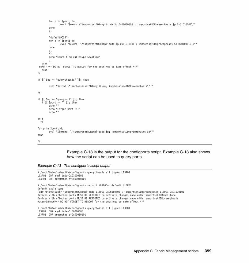
for p in $port; do eval "$excmd \"ismportsetDDRamplitude $p 0x06060606 ; ismportsetDDRpreemphasis $p 0x01010101\"" done ;;
"default9024") for p in $port; do eval "$excmd \"ismportsetDDRamplitude $p 0x01010101 ; ismportsetDDRpreemphasis $p 0x01010101\"" done ;; *) echo "Can't find cabletype $cabtype" ;; esac echo "*** DO NOT FORGET TO REBOOT for the settings to take effect ***" exitfi
if [[ $op == "querychassis" ]]; then
eval "$excmd \"ismchassissetDDRamplitude; ismchassissetDDRpreemphasis\" "
fi
if [[ $op == "queryport" ]]; then if [[ $port == "" ]]; then echo "" echo "Forgot port !!!" echo ""
exit fi
for p in $port; do eval "${excmd} \"ismportsetDDRamplitude $p; ismportsetDDRpreemphasis $p\""done
fi
Example C-13 is the output for the configports script. Example C-13 also shows how the script can be used to query ports.
Example C-13 The configports script output
# /root/fmtools/health/configports querychassis all | grep L13P01L13P01 DDR amplitude=0x01010101L13P01 DDR preemphasis=0x01010101
# /root/fmtools/health/configports setport ib9240up default L13P01Default cable type[admin@ib9240up]# ismportsetDDRamplitude L13P01 0x06060606 ; ismportsetDDRpreemphasis L13P01 0x01010101Devices with effected ports MUST BE REBOOTED to activate changes made with ismportsetDDRamplitudeDevices with effected ports MUST BE REBOOTED to activate changes made with ismportsetDDRpreemphasisMasterSpine6*** DO NOT FORGET TO REBOOT for the settings to take effect ***
# /root/fmtools/health/configports querychassis all | grep L13P01L13P01 DDR amplitude=0x06060606L13P01 DDR preemphasis=0x01010101
Appendix C. Fabric Management scripts 399

400 HPC Clusters Using InfiniBand on IBM Power Systems Servers

Appendix D. AIX ibstat -s output description
The ibstat -s flag provides statistics output for InfiniBand interfaces. The output can be split into four sections, as described in this appendix.
D
© Copyright IBM Corp. 2009. All rights reserved. 401
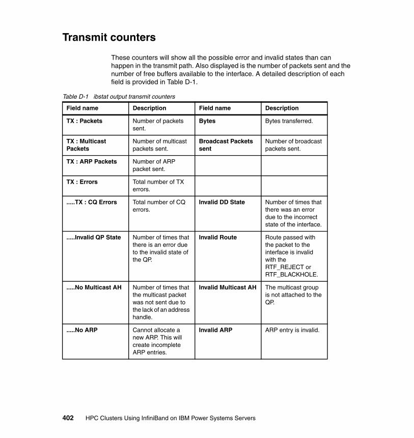
Transmit counters
These counters will show all the possible error and invalid states than can happen in the transmit path. Also displayed is the number of packets sent and the number of free buffers available to the interface. A detailed description of each field is provided in Table D-1.
Table D-1 ibstat output transmit counters
Field name Description Field name Description
TX : Packets Number of packets sent.
Bytes Bytes transferred.
TX : Multicast Packets
Number of multicast packets sent.
Broadcast Packets sent
Number of broadcast packets sent.
TX : ARP Packets Number of ARP packet sent.
TX : Errors Total number of TX errors.
.....TX : CQ Errors Total number of CQ errors.
Invalid DD State Number of times that there was an error due to the incorrect state of the interface.
.....Invalid QP State Number of times that there is an error due to the invalid state of the QP.
Invalid Route Route passed with the packet to the interface is invalid with the RTF_REJECT or RTF_BLACKHOLE.
.....No Multicast AH Number of times that the multicast packet was not sent due to the lack of an address handle.
Invalid Multicast AH The multicast group is not attached to the QP.
.....No ARP Cannot allocate a new ARP. This will create incomplete ARP entries.
Invalid ARP ARP entry is invalid.
402 HPC Clusters Using InfiniBand on IBM Power Systems Servers
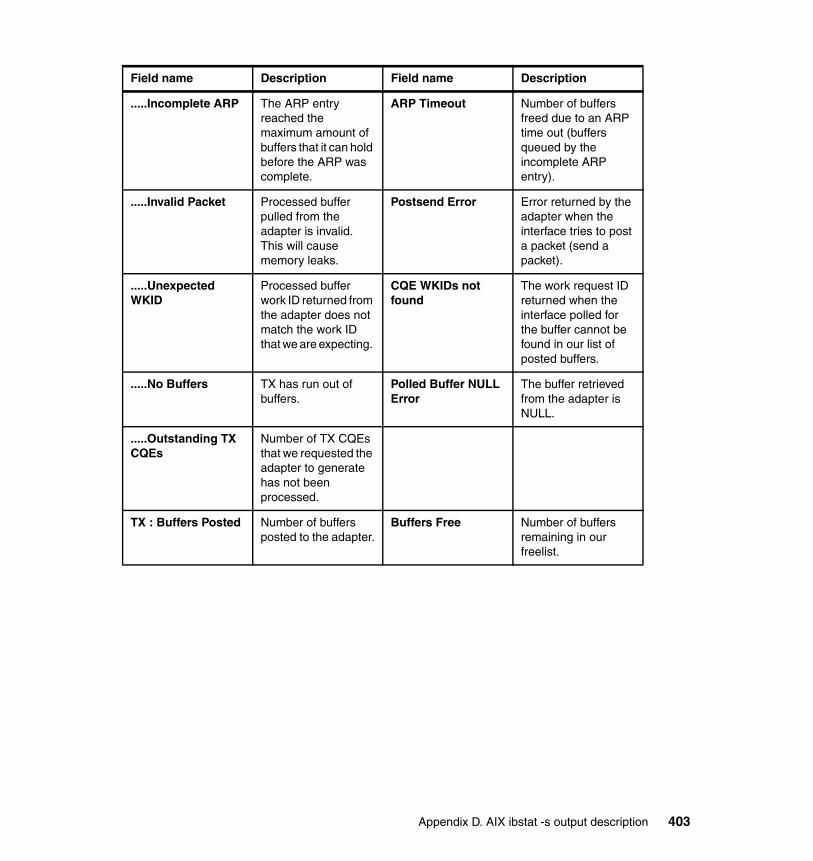
.....Incomplete ARP The ARP entry reached the maximum amount of buffers that it can hold before the ARP was complete.
ARP Timeout Number of buffers freed due to an ARP time out (buffers queued by the incomplete ARP entry).
.....Invalid Packet Processed buffer pulled from the adapter is invalid. This will cause memory leaks.
Postsend Error Error returned by the adapter when the interface tries to post a packet (send a packet).
.....Unexpected WKID
Processed buffer work ID returned from the adapter does not match the work ID that we are expecting.
CQE WKIDs not found
The work request ID returned when the interface polled for the buffer cannot be found in our list of posted buffers.
.....No Buffers TX has run out of buffers.
Polled Buffer NULL Error
The buffer retrieved from the adapter is NULL.
.....Outstanding TX CQEs
Number of TX CQEs that we requested the adapter to generate has not been processed.
TX : Buffers Posted Number of buffers posted to the adapter.
Buffers Free Number of buffers remaining in our freelist.
Field name Description Field name Description
Appendix D. AIX ibstat -s output description 403
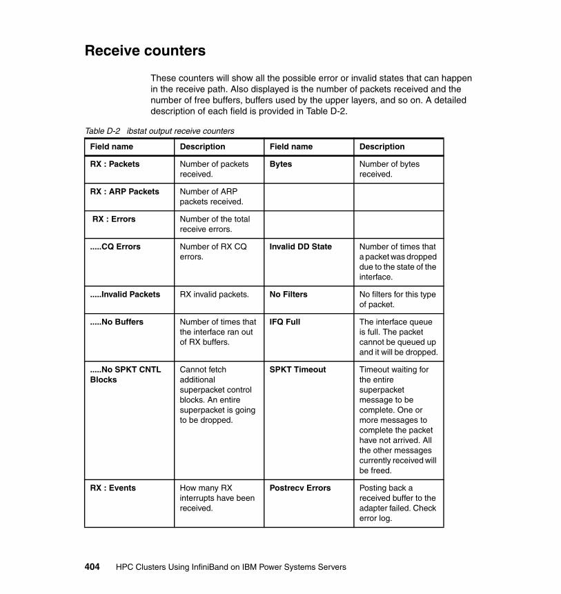
Receive counters
These counters will show all the possible error or invalid states that can happen in the receive path. Also displayed is the number of packets received and the number of free buffers, buffers used by the upper layers, and so on. A detailed description of each field is provided in Table D-2.
Table D-2 ibstat output receive counters
Field name Description Field name Description
RX : Packets Number of packets received.
Bytes Number of bytes received.
RX : ARP Packets Number of ARP packets received.
RX : Errors Number of the total receive errors.
.....CQ Errors Number of RX CQ errors.
Invalid DD State Number of times that a packet was dropped due to the state of the interface.
.....Invalid Packets RX invalid packets. No Filters No filters for this type of packet.
.....No Buffers Number of times that the interface ran out of RX buffers.
IFQ Full The interface queue is full. The packet cannot be queued up and it will be dropped.
.....No SPKT CNTL Blocks
Cannot fetch additional superpacket control blocks. An entire superpacket is going to be dropped.
SPKT Timeout Timeout waiting for the entire superpacket message to be complete. One or more messages to complete the packet have not arrived. All the other messages currently received will be freed.
RX : Events How many RX interrupts have been received.
Postrecv Errors Posting back a received buffer to the adapter failed. Check error log.
404 HPC Clusters Using InfiniBand on IBM Power Systems Servers

Asynchronous event countersThese counters show the events reported by the InfiniBand adapter to the interface. These events can be changes of port state (up/down), queue pair (QP)/completion queue (CQ) errors, multicast retransmission or errors, or adapter malfunctions.
Adapter malfunctions are analogous to EEH errors, but in this case a complete stack recycle (removal of IB interfaces, applications, connection manager, and adapter’s device driver instances) must be perform to recover the product.
RX : Packet Copies Number of times that the interface, instead of passing IB registered buffers up, will get a buffer from the system and copy the IB buffer data to the new buffer and pass it up. This will only happens if the applications are not fast enough to fetch the buffers from the sockets.
RX : Buffers Posted Number of buffers posted to the receive queue. Different from the TX queue. Normally the queue should remain almost full.
Buffers Free Number of buffers In the free list.
RX : Buffers User Buffers held by the users.
Field name Description Field name Description
Appendix D. AIX ibstat -s output description 405
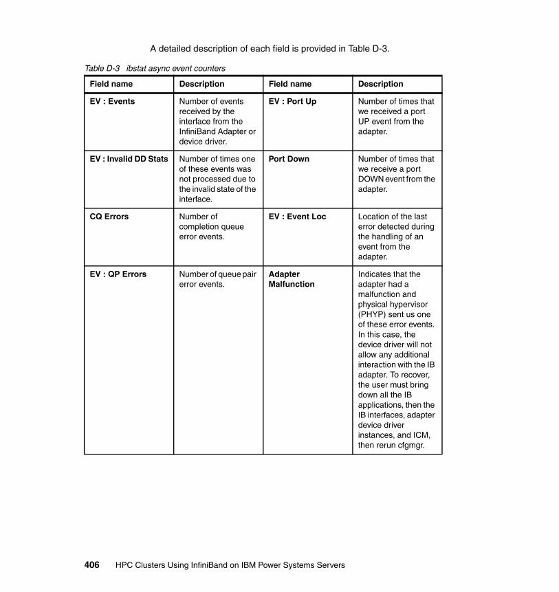
A detailed description of each field is provided in Table D-3.
Table D-3 ibstat async event counters
Field name Description Field name Description
EV : Events Number of events received by the interface from the InfiniBand Adapter or device driver.
EV : Port Up Number of times that we received a port UP event from the adapter.
EV : Invalid DD Stats Number of times one of these events was not processed due to the invalid state of the interface.
Port Down Number of times that we receive a port DOWN event from the adapter.
CQ Errors Number of completion queue error events.
EV : Event Loc Location of the last error detected during the handling of an event from the adapter.
EV : QP Errors Number of queue pair error events.
Adapter Malfunction
Indicates that the adapter had a malfunction and physical hypervisor (PHYP) sent us one of these error events. In this case, the device driver will not allow any additional interaction with the IB adapter. To recover, the user must bring down all the IB applications, then the IB interfaces, adapter device driver instances, and ICM, then rerun cfgmgr.
406 HPC Clusters Using InfiniBand on IBM Power Systems Servers
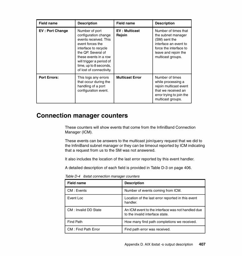
Connection manager counters
These counters will show events that come from the InfiniBand Connection Manager (ICM).
These events can be answers to the multicast join/query request that we did to the InfiniBand subnet manager or they can be timeout reported by ICM indicating that a request from us to the SM was not answered.
It also includes the location of the last error reported by this event handler.
A detailed description of each field is provided in Table D-3 on page 406.
Table D-4 ibstat connection manager counters
EV : Port Change Number of port configuration change events received. This event forces the interface to recycle the QP. Several of these events in a row will trigger a period of time, up to 8 seconds, of lost of connectivity.
EV : Multicast Rejoin
Number of times that the subnet manager (SM) sent the interface an event to force the interface to leave and rejoin the multicast groups.
Port Errors: This logs any errors that occur during the handling of a port configuration event.
Multicast Error Number of times while processing a rejoin multicast event that we received an error trying to join the multicast groups.
Field name Description Field name Description
Field name Description
CM : Events Number of events coming from ICM.
Event Loc Location of the last error reported in this event handler.
CM : Invalid DD State An ICM event to the interface was not handled due to the invalid interface state.
Find Path How many find path completions we received.
CM : Find Path Error Find path error was received.
Appendix D. AIX ibstat -s output description 407
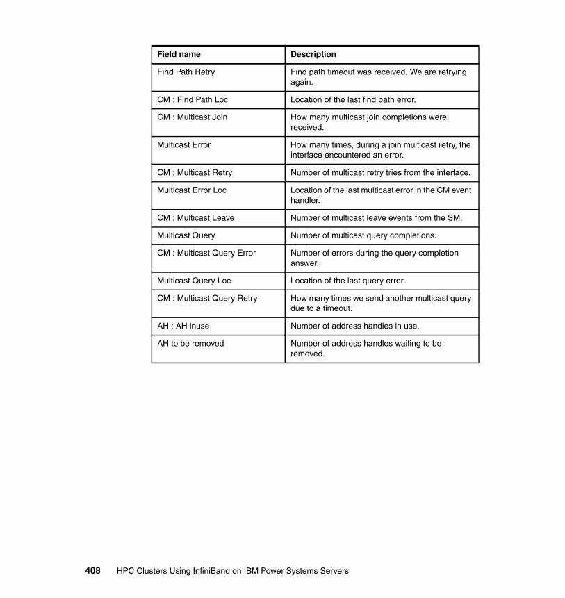
Find Path Retry Find path timeout was received. We are retrying again.
CM : Find Path Loc Location of the last find path error.
CM : Multicast Join How many multicast join completions were received.
Multicast Error How many times, during a join multicast retry, the interface encountered an error.
CM : Multicast Retry Number of multicast retry tries from the interface.
Multicast Error Loc Location of the last multicast error in the CM event handler.
CM : Multicast Leave Number of multicast leave events from the SM.
Multicast Query Number of multicast query completions.
CM : Multicast Query Error Number of errors during the query completion answer.
Multicast Query Loc Location of the last query error.
CM : Multicast Query Retry How many times we send another multicast query due to a timeout.
AH : AH inuse Number of address handles in use.
AH to be removed Number of address handles waiting to be removed.
Field name Description
408 HPC Clusters Using InfiniBand on IBM Power Systems Servers
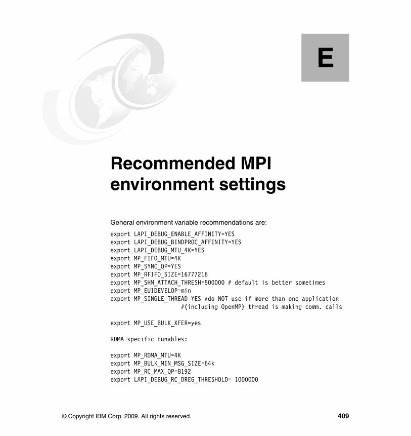
Appendix E. Recommended MPI environment settings
General environment variable recommendations are:
export LAPI_DEBUG_ENABLE_AFFINITY=YES export LAPI_DEBUG_BINDPROC_AFFINITY=YES export LAPI_DEBUG_MTU_4K=YESexport MP_FIFO_MTU=4Kexport MP_SYNC_QP=YESexport MP_RFIFO_SIZE=16777216export MP_SHM_ATTACH_THRESH=500000 # default is better sometimesexport MP_EUIDEVELOP=min export MP_SINGLE_THREAD=YES #do NOT use if more than one application #(including OpenMP) thread is making comm. calls
export MP_USE_BULK_XFER=yes
RDMA specific tunables:
export MP_RDMA_MTU=4Kexport MP_BULK_MIN_MSG_SIZE=64kexport MP_RC_MAX_QP=8192export LAPI_DEBUG_RC_DREG_THRESHOLD= 1000000
E
© Copyright IBM Corp. 2009. All rights reserved. 409

export LAPI_DEBUG_QP_NOTIFICATION=noexport LAPI_DEBUG_RC_INIT_SETUP=yes#try both = yes and = no
LAPI_DEBUG_ENABLE_AFFINITY=YES
The default value of LAPI_DEBUG_ENABLE_AFFINITY changes to NO in rsct.lapi.rte 2.4.5.4 and the base of rsct.lapi.rte 2.4.6.0. A future service update will change the default for this variable back to YES. A goal of the LAPI team is to remove the need for setting any LAPI_DEBUG variables in future service updates.
Setting this variable to YES allows the communication protocols to exploit adapter affinity when possible. For example, for FIFO/UD (non-RDMA) traffic, an MPI task running on a 575 node will attempt to send over a link on a GX++ bus that is in the same quad to which the task is bound. Without setting this variable MPI tasks will not make affinity choices, but will simply attempt to achieve, across all MPI tasks on a node, even use of the available links.
Note that, for an adapter affinity choice to be made, an MPI task must already be bound at MPI_Init() time. In the original code release, only tasks bound via an rset could determine adapter affinity, but, starting in rsct.lapi.rte 2.4.5.4 and rsct.lapi.rte 2.4.6.0, tasks bound with bindprocessor can determine affinity if LAPI_DEBUG_BINDPROC_AFFINITY is set to YES.
LAPI_DEBUG_BINDPROC_AFFINITY=YES
LAPI_DEBUG_BINDPROC_AFFINITY was added in rsct.lapi.rte 2.4.5.4 and rsct.lapi.rte 2.4.6.0. Currently, this variable must be explicitly set to YES to allow affinity choices to be correctly made when binding with bindprocessor (for example, when using the 'launch' binding tool), but a future service update will change the default behavior to allow correct affinity choices to be made when using bindprocessor, even if LAPI_DEBUG_BINDPROC_AFFINITY is not explicitly set.
LAPI_DEBUG_MTU_4K=yes
In the most recent LAPI levels at the time of this writing (rsct.lapi.rte 2.4.5.4 and 2.4.6.2) you are required to set LAPI_DEBUG_MTU_4K=yes and MP_FIFO_MTU=4K to get the full benefit of 4K MTU. In a future service update,
410 HPC Clusters Using InfiniBand on IBM Power Systems Servers
4K MTU will be controlled via setting MP_FIFO_MTU alone and setting this debug variable will have no effect.
Unless 4K MTU is requested, FIFO/UD uses a default 2 K packet. FIFO bandwidths can be improved by setting this variable to 4K to enable 4K MTU for FIFO packets. Note that the switch chassis MTU must be enabled for 4K MTU for this to work.
MP_FIFO_MTU=4K
Unless this is set, FIFO/UD uses a default 2K packet. FIFO bandwidths can be improved by setting this variable to 4K to enable 4K MTU for FIFO packets. Note that the switch chassis MTU must be enabled for 4K MTU for this to work.
MP_SYNC_QP=YES
On IB systems, QP information must be exchanged between two tasks before messages can be sent. For FIFO/UD traffic, we recommend that the exchange of this information be done in MPI_Init() by setting MP_SYNC_QP=YES. By forcing this QP exchange to occur up-front, some variation in communication performance can be eliminated. In the latest LAPI levels (2.4.6.3) the default for this variable is changed from NO to YES.
MP_RFIFO_SIZE=16777216
The default size of the receive FIFO used by each MPI task is 4 MB. We recommend using larger jobs to use the maximum size receive FIFO by setting MP_RFIFO_SIZE=16777216.
MP_SHM_ATTACH_THRESH=500000
LAPI has two modes of sending shared memory messages. For smaller messages slot mode is used to copy messages from one MPI task to another. On AIX only, for larger messages, it is possible to map the shared memory segment of one task to another, thereby saving a copy at the cost of some overhead of attaching. The MP_SHM_ATTACH_THRESH variable defines the minimum size message for which attach mode is used. Depending on the type of job, different cross-over points may provide optimal performance, but 500000 is often a
Appendix E. Recommended MPI environment settings 411

reasonable starting point when tuning this value. The default depends on how many tasks are running on the node.
Note that, starting in rsct.lapi.rte 2.4.5.4 and 2.4.6.0, this MP variable replaces the previous DEBUG_variable, LAPI_DEBUG_SLOT_ATT_THRESH. In earlier service pack levels, LAPI_DEBUG_SLOT_ATT_THRESH has the same function as MP_SHM_ATTACH_THRESH.
MP_EUIDEVELOP=min
The MPI layer will perform checking on the correctness of parameters according to the value of MP_EUIDEVLOP. As these checks can have a significant impact on latency, when not developing applications we recommend that MP_EUIDEVELOP=min be set to minimize the checking done at the message passing interface layer.
MP_SINGLE_THREAD=yes
Setting MP_SINGLE_THREAD=yes can improve latency by eliminating locking between LAPI and MPI. This should not be set if a single MPI task (process) has multiple user threads making MPI calls. This should also not be set =YES for hybrid MPI/OpenMP applications if multiple OpenMP threads are making communications calls, though it should be noted that by default such hybrid codes only make MPI calls from the main (master) OpenMP thread.
MP_USE_BULK_XFER=yes
Setting MP_USE_BULK_XFER=yes will enable RDMA. On IB systems using RDMA will generally give better performance at lower task counts when forcing RDMA QP information to be exchanged in MPI_Init() (via setting LAPI_DEBUG_RC_INIT_SETUP=yes). When the RDMA QP information is not exchanged in MPI_Init(), there can be delays due to QP information exchange until all tasks have synced-up.
The benefit of RDMA depends on the application and its use of buffers. For example, applications that tend to re-use the same address space for sending and receiving data will do best, as they avoid the overhead of repeatedly registering new areas of memory for RDMA.
412 HPC Clusters Using InfiniBand on IBM Power Systems Servers

RDMA mode will use more memory than pure FIFO mode. Note that this can be curtailed by setting MP_RC_MAX_QP to limit the number of RDMA QPs that are created.
MP_RDMA_MTU=4K
Unless this is set, RDMA uses the default of a 2K packet. RDMA bandwidths can be improved by setting this variable to 4K to enable 4K MTU for RDMA packets. Note that the switch chassis MTU must be enabled for 4K MTU for this to work.
MP_BULK_MIN_MSG_SIZE=64k
The minimum size message used for RDMA is defined to be the maximum of MP_BULK_MIN_MSG_SIZE and MP_EAGER_LIMIT. So if MP_EAGER_LIMIT is defined to be higher than MP_BULK_MIN_MSG_SIZE, the smallest RDMA message will be limited by the eager limit.
MP_RC_MAX_QP=8192
This variable defines the maximum number of RDMA QPs that will be opened by a given MPI task. Depending on the size of the job and the number of tasks per node, it may be desirable to limit the number of QPs used for RDMA. By default, when the limit of RDMA QPs is reached, future connections will all use FIFO/UD mode for message passing.
LAPI_DEBUG_RC_DREG_THRESHOLD= 1000000
This value defines the number of LAPI timer ticks (an interval defined by MP_POLLING_INTERVAL) that must occur before a given RDMA memory region, which has no in-flight RDMAs associated with it, becomes a candidate for RDMA deregistration.
Increasing this value can delay or prevent performance delays associated with memory deregistration.
The default value (in the latest rsct.lapi.rte 2.4.5.4 and the base of rsct.lapi.rte 2.4.6.2 levels) is 10, which, with the default MP_POLLING_INTERVAL, means that a memory region may be deregistered four seconds after it is last used for
Appendix E. Recommended MPI environment settings 413

RDMA. However, in a future service update, the default value will be changed to prevent the need for explicitly setting this value via the LAPI DEBUG variable.
LAPI_DEBUG_QP_NOTIFICATION=no
Setting this variable to NO prevents the generation of interrupts on RDMA completions. When an application is in polling mode (which is the default, MP_CSS_INTERRUPT=no) separate interrupts are not required, so some performance overhead can be eliminated by setting this variable to NO. In a future service update, the default value of this variable will be changed to prevent the need for setting the LAPI DEBUG variable explicitly.
LAPI_DEBUG_RC_INIT_SETUP=yes
Setting this variable will force all RDMA QP exchanges to occur in MPI_Init(). This can be useful for smaller jobs (typically 256 MPI tasks or less)
Other variables to experiment with are discussed next.
LAPI_DEBUG_RDMA_AFFINITY=YES
This forces each task to only use the two affinity links for RDMA, so the total bandwidth available to each task will be less but the overall bandwidth on the node may be more efficiently used. So far, this has only been useful in a few cases. RDMA uses a link on all networks, for example, eight links on an 8- switch system, unless this variable is set.
MP_POLLING_INTERVAL=800000
This defines the interval at which the LAPI timer thread runs. Setting the polling interval equal to 800000 defines an 800-millisecond timer. The default is 400 milliseconds.
414 HPC Clusters Using InfiniBand on IBM Power Systems Servers
MP_RETRANSMIT_INTERVAL=8000000
This defines the number of loops through LAPI dispatch code before retransmission logic kicks in. The polling interval also comes into play in the calculation of when retransmission will occur. If the network is very stable, setting this value to 800000 or higher (the default is 400000) can improve performance by eliminating unneeded retransmission.
LAPI_DEBUG_SEND_FLIP=8
For FIFO traffic, this will allow LAPI to use more than one link, switching every X number of packets between FIFOs. In some cases enabling this variable can increase performance.
LAPI_DEBUG_ACK_THRESH=16
This defines how many packets we receive before sending an ACK (the default is 31). The sender can block on ACKs after sending 64 packets to a given destination without receiving an ACK. In certain cases, setting this variable can improve performance.
MP_BULK_XFER_CHUNK_SIZE=1024k
This defines how large a chunk size we ask RDMA transmissions to use. The default value is 32768k, but in some cases a smaller value, such as 1024k, may improve performance.
Appendix E. Recommended MPI environment settings 415

416 HPC Clusters Using InfiniBand on IBM Power Systems Servers
Related publications
The publications listed in this section are considered particularly suitable for a more detailed discussion of the topics covered in this book.
IBM Redbooks publications
For information about ordering these publications, see “How to get Redbooks publications” on page 418. Note that some of the documents referenced here may be available in softcopy only.
� Building a Linux HPC Cluster with xCAT, SG24-6623
� Linux HPC Cluster Installation, SG24-6041
Other publications
These publications are also relevant as further information sources:
� In Search of Cluster, Gregory F. Pfister, ISBN-13: 978-0134376257
� An Introduction to the InfiniBand Architecture, Chapter 42, Gregory F. Pfister
� White paper, InfiniBand Software and Protocols Enable Seamless Off-the-shelf-Application Deployment, Mellanox, December 2007
� High performance computing technology, applications and business, Dr. Luigi Brochard, Article, Informatik Spektrum, 29 March 2006
� Site and Hardware Planning Guide, SA76-0091-00
Online resources
These Web sites are also relevant as further information sources:
� IBTA
http://www.infinibandta.org
� PCI Express Bus
http://www.interfacebus.com/Design_Connector_PCI_Express.html
© Copyright IBM Corp. 2009. All rights reserved. 417
� Mellanox
http://www.mellanox.com/pdf/whitepapers/IB_Intro_WP_190.pdf
� OpenFabrics Alliance
http://www.openfabrics.org/
� IBM
– Power Systems Site and hardware planning
http://publib.boulder.ibm.com/infocenter/systems/scope/hw/topic/iphad/iphad.pdf
– Power Systems Site preparation and physical planning
http://publib.boulder.ibm.com/infocenter/systems/scope/hw/topic/arebe/arebe.pdf
How to get Redbooks publications
You can search for, view, or download Redbooks publications, Redpapers publications, Technotes, draft publications and Additional materials, as well as order hardcopy Redbooks publications, at this Web site:
ibm.com/redbooks
Help from IBM
IBM Support and downloads
ibm.com/support
IBM Global Services
ibm.com/services
418 HPC Clusters Using InfiniBand on IBM Power Systems Servers
Index
Numerics0x00000 HopLimit 311–31316-bit counter 384–3854-bit counter 383–3848-bit counter 382, 385
Aaccess pattern 141address handle (AH) 24, 402AIX xvAIX 6.1 TL3 163, 166, 175–176, 213, 227–228, 231
none 175AIX DVD 208, 213AIX Workload Manager 112Anafa2 issue 196API 97Application cluster 17application programming interface (API) 90, 97, 112, 114, 116, 118–119, 148archive system 156arp command 93, 355ARP entry 356, 402
Bbase Lid 117–119, 359–360base operating system (BOS) 208base OS 328Baseboard manager (BM) 104–105BM function 31broadcast/multicast group 95Bulk Power Assembly (BPA) 102Bulk Power Hub (BPH) 102Bulk Power HubEach (BPH) 165, 167
CCA IBM G2 Logical HCA 292–293, 309, 311–313central electronic complex (CEC) 16, 135central processing unit (CPU) 129, 346, 349–350, 364channel adapter (CA) 7, 21–23, 26–27, 29, 33, 37, 94, 104, 115, 285–286, 292, 294, 297, 306–307, 309, 311–313
© Copyright IBM Corp. 2009. All rights reserved.
Chassis Management Unit (CMU) 106chtab key 212, 241CLI mode 186–187cluster component 101, 130–131, 149–150, 152, 163–164, 186Cluster management
network 101, 152software 149, 158software hide 149tool 132, 179
Cluster Ready Hardware Server (CRHS) 102Cluster systems Management (CSM) 88, 109Communication Manager
Abstraction 97Communication Manager Abstraction (CMA) 97Communication semantics 24, 26completion queue
completed requests 24Completion Queue (CQ) 23, 405–406completion queue entry (CQE) 37Configuring php-syslog-ng 371, 379constant bisectional bandwidth (CBB) 305CQ Error 354, 402, 404, 406
Total number 402CRC 36
DData collection 327DDR speed 306default MP_POLLING_INTERVAL 413destination QPN 22, 26DETAIL
Node type 344device driver 7, 22–23, 92–94, 96, 98, 113, 357, 405device name 118, 352–353, 356device naming
different order 171devices does not represent (DDR) 289, 305–306DHCP server 165–166, 244DNS server 238
419
Ee.g. memory 364EEH error 405End node 6, 29–30
possible paths 29error FNOT_FOUND 318ethernet access 105Ethernet connection 102EV 354Event Loc 354, 406–407export FF_ALL_ANALYSIS 197
FFabric Executive (FE) 31, 104–106fabric for clustering (FC) 13, 20Fabric Management
Server 103fabric management 7, 28–29, 89, 100, 103, 136–137, 152, 284, 337, 365
external server 137Fabric Manager (FM) 101, 103–104, 106, 180, 185, 190, 192–193, 197–198, 200–201, 216, 323–324, 343, 346Fabric Manager Server 185, 193Fabric software 327Fabric Suite FastFabric Toolset (FFT) 105Failover 334, 337FastFabric Toolset 103, 105, 284Fibre Channel 10, 13–14, 36, 39, 206, 236, 267FIFO packet 411file system 88, 112–113, 141, 145, 193, 208, 224, 256, 267, 269, 271, 334
Completed creation 224fileset 94filter itso_err 254first HCA
first port 286Flexible Service ProcessorsThe (FSP) 102, 108FLoating Point Operation
approximate number 127FlowLabel 311–313fm nodetype 216, 249FPU 127, 133FV communicate 106
GGbps 94, 362General Parallel File System (GPFS) 88, 101,
112–114, 141–143, 145–146, 155–156, 158, 206, 217, 219, 221–224, 230, 258–259General Service Interface (GSI) 32–33Gigabit Ethernet 5, 19, 37, 135Global Identifier (GID) 27, 91–92, 118Global Route Header (GRH) 27GPFS client 141, 167, 222, 224GPFS cluster 113–114, 141, 144–145, 219, 221–222, 224, 266–267
specific file systems 145GPFS package 220GPFS user 142GPFS version 114
3.2.1.12 236graphical user interface (GUI) 104, 106, 148grep iview 201, 318, 326GX bus
adapter 15connection 15
GX bus (GB) 15–16, 224, 269GX+/GX++ HCA
port 383
Hhardware maintenance 327Hardware Management 101–102, 105, 110, 241
Console 101–102, 165, 241, 246, 290, 317Hardware Management Console (HMC) 162, 165, 173HCA 96HCA card 11HCA-1 Guid 202HCAD 94HCAs 199, 201, 285–287, 290, 292, 309–311, 317, 320, 324, 328–329, 340, 342–343, 355, 365head of queue (HOQ) 308hierarchical storage management (HSM) 136, 141–142, 146, 284, 331High Performance Computing (HPC) 3, 18, 40, 87–89, 100, 102–103, 114, 117, 124, 174, 205–206, 217, 236, 238, 247, 253, 257–258, 266, 340, 344, 347, 364–365High Performance Switch (HPS) 136HMCs 212, 366Host Channel Adapter
Device 94, 98, 352host channel adapter (HCA) 4, 6–7, 118, 287, 306, 348, 352
420 HPC Clusters Using InfiniBand on IBM Power Systems Servers

Host Channel Adapter Device (HCAD) 352–353host.list file 229, 232, 234, 278–279HPC xvHPC application 8, 125HPC area 126HPC cluster 1, 19, 88, 123–124, 128, 130, 139, 146, 150–151, 153–154, 156–158, 161, 236, 238
Common uses 19configuration 153customer 151installation 206
HPC environment 25, 33, 87, 121, 128, 132, 139–140, 189, 203HPC product 136HPC software 162–163, 218, 257, 347HPC solution 89HPC system 121, 123, 125, 128, 130
Design criteria 125
II/O architecture 3, 12I/O capability 128I/O Controller 7IB 96IB infrastructure 18, 179IB link 135IB network 38IB packet
IP packet 92IB packet (IP) 89, 91–93, 97, 102, 105, 114, 117–118, 163–168, 172, 174, 178, 180, 182–185, 187, 189, 191, 193–195, 206, 208, 218, 221, 225, 230, 233–234, 236, 238, 251, 253, 255, 257, 271, 278–279, 340–341, 344–345, 349–350, 356IB port
side 181stat 366
IB subnet 28–29, 31, 286IB switch
chip 95, 99CLI 189environment 136selection 136setting 90
IB system 411–412IBA component 29, 33iba_report command 286, 296–297, 302, 305ib-domain (ID) 246, 248, 272
IBM xvIBM 7874 88, 178, 180, 182, 295, 300, 308, 310–311, 321
Front picture 180front picture 180leaf 10 310
IBM HPC 167, 175, 217, 257IBM Power System
p575 134server 101
IBM System pcluster 288Logical Partitioning 8server 87, 110, 139
IBM.Netw orkInterface 117–119, 351IBMs offer 141, 146, 148ibstat 352IBTA 96InfiniBand cable 12, 178, 298InfiniBand communication 20, 25InfiniBand Communications Manager (ICM) 90InfiniBand Connection
Manager 23, 94, 407InfiniBand Connection Manager (ICM) 406–407InfiniBand environment 281InfiniBand Fabric
Congestion 365Suite 103
InfiniBand fabric 21, 30, 37, 172, 177–179, 219, 347–348, 365
configuration 178environment 178
InfiniBand Fabric Suite (IFS) 103, 105–106InfiniBand network 24, 27, 33, 138, 156, 167, 221
switch IP 167InfiniBand standard 1InfiniBand switch 87, 164, 171, 178–180, 183–184, 188–189, 203, 208, 216, 249, 338
basic configuration 180management functions 101network management ethernet cables 178
Infiniband SwitchFabric Configuration 174plane 1 IP address 167
InfiniBand technology 39, 132, 136InfiniBand Trade Association (IBTA) 104, 286, 290, 302, 330Information Lifecycle Management (ILM) 141infrastructure offloads (I/O) 89, 101, 108, 114–116,
Index 421

223, 225initial cost 128internal switch link (ISL) 105, 310Internet Protocol 18, 34, 90IP 97IP address 118, 163–164, 166–167, 169, 182–183, 185, 195, 206, 236, 254, 317IP information 351IP label 167, 195IP message 233, 278
JJob Management System (JMS) 147–148job run 119Job scheduler 147–148
KkB 332
LLAPI 114LAPI package 260LAPI_DEBUG variable 410Level Application Programming Interface (LAPI) 206, 217, 228, 236, 257, 260, 262, 265–266LIDs 26–27, 32, 117, 119, 309, 337Linux box 183, 188Linux distribution 114, 140LL 257, 262, 265, 272LL rpm 259–261, 265, 270llextRPD 272LMC 26–27loadl 262loadl user 262, 272loadl.sh postscript 265Local Id (LID) 199, 316, 318, 326local route header (LRH) 91Logical HCA 199, 202, 291–292, 297, 309, 311–313, 323, 327Logical Switch 199, 202, 287, 291, 293, 295, 297, 299–300, 302–303, 310–313, 323, 325, 327long wave (LW) 14low latency 15, 18, 21, 38, 88, 94, 98, 101, 114–115, 140Lower Level Protocol (LLP) 90Low-latency link 19low-level application programming interface 114
LPP file 227–228, 231
MManagement Datagrams 28, 32Management interface 32Management Node (MN) 101–102, 109, 179, 186, 188, 190–192, 206–209, 212, 220, 232, 236–239, 253, 258, 260, 265Management Server 102–103, 109, 137, 152, 166, 206–207, 209–210, 212, 236, 239, 244, 249, 262, 271–272, 286, 290, 322, 329, 331, 341, 344, 346, 365master SM 29–30, 32, 323Master Spine 183, 187, 189, 300maximum number 136–137, 199, 289, 347, 356, 413memory region
Register large page 94memory region (MR) 24, 94, 96, 413Message Passing Interface (MPI) 8, 19, 25, 88, 116, 119min 335–337misconfigured link 287MP variable 412MPI 114MPI application 148MPI message 171, 232, 277MPI Source 193–194, 331MPI task 410–412ms Pref 311–313MTU 93–95, 98, 185, 199–200, 287, 292, 294–295, 297, 299–301, 303, 307, 311–313, 320, 347, 350MTU setting 320Multicast Error 354multicast group 285, 319, 334, 402Multicast Leave 355, 408multicast membership 98Multicast Query 355, 408
Error 355, 408Loc 355
multicast service 91multilink 218–219, 257, 350Multiple Program Multiple Data (MPMD) 115–116
Nnetwork file service (NFS) 143Network Shared Disk (NSD) 143–144, 219, 221, 223, 266, 268–269
422 HPC Clusters Using InfiniBand on IBM Power Systems Servers

NIC 97, 193–194, 330NIM master 208, 214, 232NIM resource 208, 214, 216nmon tool 349–350nodeguid 291–293non-root user 228, 232, 234, 277, 279non-zero threshold 395NRT 118–119NSD client 221, 266NSD disc 267–268NSD name 113NSD protocol 143
OObject name 211, 214, 243, 246OFED 96OFED iSER 193–194, 331OFED iWARP 193–194, 331OFED RDS 193–194, 331OFED SDP 193–194, 331OFED service 363OFED stack 96
Application layer 97Core layer 96Driver layer 96Upper level protocol layer 97User space API layer 97
OFED uDAPL 193–194, 331OFED version 330Open Fabric
Alliance 103Alliance InfiniBand 103Enterprise Distribution 103, 328, 330
Open Fabrics Enterprise Distribution 96Open Firmware 213OpenFabrics Enterprise Distribution (OFED) 5, 96–98operating system
individual copy 113single copy 6
operating system (OS) 6, 8, 90, 101, 108, 110, 113, 115, 131, 133, 139, 157, 163, 188, 191–192, 206, 208, 236, 238, 242, 244, 246, 250, 259, 285, 328, 331, 345, 350output type 286–287, 292, 305, 309
PParallel Environment (PE) 89, 114–115, 117, 125,
217, 257parallel operating environment (POE) 115parallel program 115–116, 229parallel task 115–116, 148PCI Express 15PE package 228, 261PE/POE documentation 171–172Performance manager (PM) 104–105performance requirement 137, 144physical hypervisor 406physical MTU
size 95physical port 26, 104, 291, 316, 318
local addresses 104multiple virtual ports 26
PKey 310, 312–313PNSD 118–119POE 115POE IVP 229POE IVP_r 229port 2
0x0002550040549711 343port counter 105, 297, 299–300, 302, 381, 384, 389–392
detailed description 381detailed explanation 298main types 298
port y 195PortRcvErrors counter 299power switch 366Protection Domain (PD) 24
QQLogic Fabric Manager 101, 197, 284, 286, 291, 302, 320–322, 330, 333, 337, 382
configuration 9HCA connections ismportsetDDRamplitude 321management functions 101valid input flag 286
QLogic Fabric Manager HCA connections 321QLogic FM 193–194, 331QLogic SRP 193–194, 330QP Error 354Quality of Service (QOS) 16, 30Queue Manager
contact 147module 147
Index 423
queue pairnumber 22, 26, 91, 119state 120
Queue Pair (QP) 91, 119, 402, 405–407
RRC Transport 25RC transport
layer 25layer guarantees reliability 25
rCxt Blks 276RDMA operation 25RDMA QPs 413RDS protocol 37Real Application Clusters (RAC) 38Receive Queue (RQ) 21, 24Redbooks Web site 418
Contact us xviiiredundant mode 152Reliable Connection (RC) 25, 36Reliable Datagram (RD) 25, 37Reliable Scalable Clustering Technology (RSCT) 111, 217, 257Remote Direct Memory Access (RDMA) 5, 17, 25, 35request for proposal (RFP) 124required to copy (RC) 90, 98RMC 264, 269round-trip time (RTT) 19RPD 270RPD domain 230RS232 port 184RSCT Peer Domain (RPD) 230, 270, 272, 351rsct.basi c-2.5.3.1-09118 265, 270rsct.core.cimr m-2.5.3.1-09118 265, 270rsct.core.util s-2.5.3.1-09118 265, 270rsct.lapi.rte 2.4.5.4 410, 412–413rsct.lapi.rte 2.4.6.0 410
SSCSI RDMA Protocol (SRP) 36, 39SDR rate 306second pause 335–336second reboot 300Send Queue (SQ) 21, 24several management (SM) 7, 30–31, 91, 194, 197, 199–202Shared bus 3, 12–15
Shared Receive Queues (SRQ) 25short wave (SW) 13–14Single Program Multiple Data (SPMD) 115–116size 31457280 KB 224, 269SLES xvSLES 11 110, 163, 166, 175–176, 192, 236, 238, 244, 249, 280, 328, 371
Compiler 175compiler functionality 175
slot 101 301, 329slot reboots 301slowlinks 197, 202, 287, 305, 315, 394SM
fm02port 1 343
sm instance 323Small Computer System Interface (SCSI) 13SMs 29–30, 32, 200Sockets Direct Protocol (SDP) 17, 34, 38SSH key 189–190, 200, 216, 249, 267
exchange 197, 267string 189
SSL communication 370standard nomenclature 11standby SMs 29State
Master (SM) 195, 197, 199, 201–202, 287, 307, 309, 311, 318, 323–325, 327, 331, 333, 337, 343, 347, 359–360
storage device 8, 14, 140, 146IB adapters 8
subnet management agent (SMA) 23, 29, 32Subnet Management Interface (SMI) 32–33subnet manager
cross references data 285minor performance drop 303
subnet manager (SM) 7, 29, 91, 104, 117, 285, 291, 302, 307–308, 318, 323, 325, 332, 337, 343, 385, 407subnets 104, 106, 286super packet
feature 96SUSE Linux Enterprise Server (SLES) 191–192SW component 117Switch CLI interface 288Switch fan 334switch leaf 324, 335Switch spine 335switches, elapsed time (SET) 283, 285–286,
424 HPC Clusters Using InfiniBand on IBM Power Systems Servers

288–289, 297, 317, 319–320, 324, 327, 337SymbolErrorCounter 295, 297–298, 300, 302–303, 384syslog 237, 245, 249, 251–252, 254–256, 260, 262, 265–266, 341, 343, 345system administrator 9, 31, 109–110, 115, 132, 254, 346, 349System p 102
cluster 138Linux driver 98machine 113node 202server 132, 202
Ttabdump postscript 245, 251, 260, 262, 265–266tabdump site 241target channel adapter (TCA) 4, 7–8TClass 311–313text user interface (TUI) 195, 284Textual User Interface (TUI) 105Tivoli Workload Scheduler (TWS) 116, 148topas 349total cost of ownership (TCO) 151translation lookaside buffer (TLB) 133TWS xv
UUD mode 91
InfiniBand packet 91UD QP 26UDP protocol 254UDP/IP library 233, 278Unreliable Connection (UC) 25unreliable datagram
QPN 92user 90
Unreliable Datagram (UD) 25–26, 30, 33, 90–91, 94, 98, 119Upper Hemisphere
spine 6 185upper hemisphere 108, 182, 185, 289, 300, 308, 310
leaf port 308upper layer
protocol 3, 34, 89User Space
library 233, 278
packet mode 89protocol 114
user spaceIB verbs call 118verb 90
user workload 297, 303, 316, 334–335, 337user-created thread 171, 232, 277User-Space message 233, 278
Vvirtual file system (VFS) 113virtual interface 93
real network interfaces 93
Wwork queue
entry 37pair 37processing stop 120
XxCAT 88, 109, 235–242, 244–246, 249, 251–253, 258, 260, 262, 264–265, 272, 280, 344xCAT 2 109, 236–237xCAT database 242, 245
postscripts table 245xCAT documentation 280xCAT installation 211, 238, 240xCAT management node 208, 238–239, 261, 340, 344
install/postscripts directory 340RSCT installation packages 264
xCAT management server 166bundled ISC DHCP server 166
xCAT2 documentation 166, 173, 179xCAT2 installation 174, 208xCAT2 Management Server 162, 165–166, 173–174, 186–187, 189, 346, 366xCAT2 management server
FTP server 187public SSH key 189SSH keys 189
Index 425

426 HPC Clusters Using InfiniBand on IBM Power Systems Servers

HPC Clusters Using InfiniBand on IBM Pow
er Systems Servers
HPC Clusters Using InfiniBand on IBM
Power System
s Servers
HPC Clusters Using InfiniBand on IBM
Power System
s Servers
HPC Clusters Using InfiniBand on IBM Pow
er Systems Servers

HPC Clusters Using InfiniBand on IBM
Pow
er Systems Servers
HPC Clusters Using InfiniBand on IBM
Pow
er Systems Servers

®
SG24-7767-00 ISBN 073843339X
INTERNATIONAL TECHNICALSUPPORTORGANIZATION
BUILDING TECHNICALINFORMATION BASED ONPRACTICAL EXPERIENCE
IBM Redbooks are developed by the IBM International Technical Support Organization. Experts from IBM, Customers and Partners from around the world create timely technical information based on realistic scenarios. Specific recommendations are provided to help you implement IT solutions more effectively in your environment.
For more information:ibm.com/redbooks
®
HPC Clusters Using InfiniBand on IBM Power Systems Servers
Architecture, terminology, and concepts
Planning and implementation guidance
Useful examples and scenarios
This IBM Redbooks publication provides information about the InfiniBand standard and how the standard has been implemented to support IBM High Performance Computing (HPC) clusters.
This book will help you understand, plan, implement, and manage InfiniBand using IBM servers and switches to form a high-bandwidth, low-latency communication network for applications.
This book presents the software and hardware components that must be brought together to form the management and application foundation. We cover cluster management, node installation, monitoring the infrastructure, and application support, such as IBM TWS LoadLeveler, Parallel Environment, and various other AIX and SUSE SLES tools.
This book is intended for IT architects, system designers, data center planners, and system administrators who must design, configure, and manage an InfiniBand infrastructure in an HPC cluster.
Back cover