Embed Size (px)
Citation preview
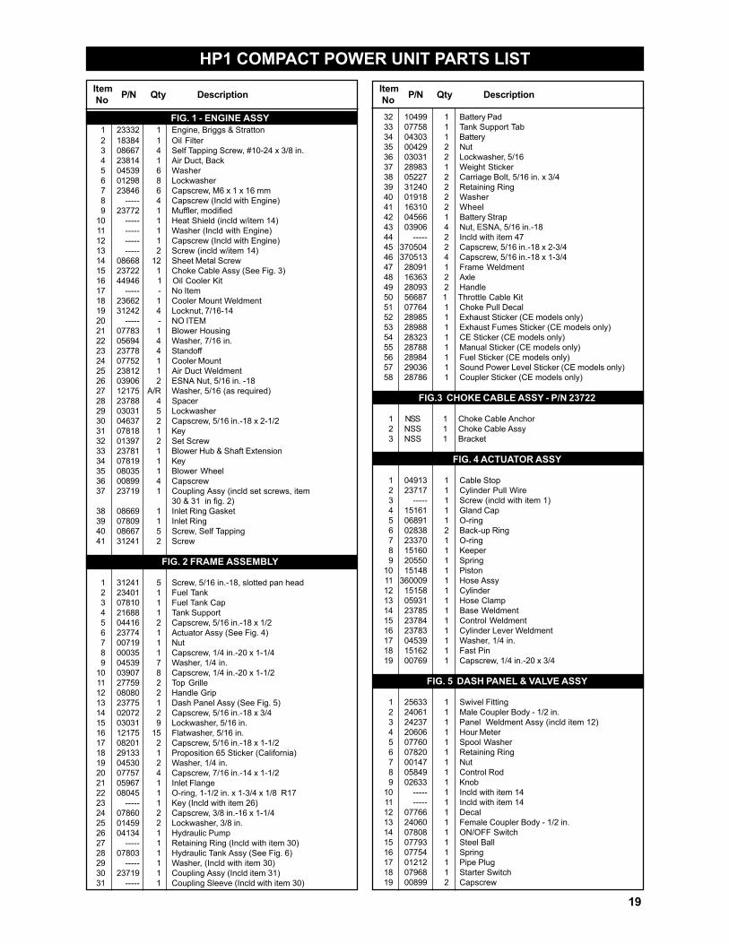
HP1 COMPACT POWER UNIT PARTS LIST
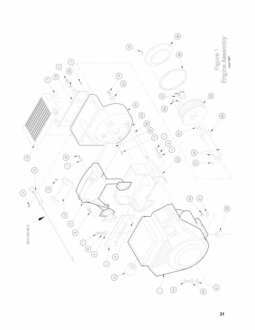
FIG. 1 - ENGINE ASSY1 23332 1 Engine, Briggs & Stratton2 18384 1 Oil Filter3 08667 4 Self Tapping Screw, #10-24 x 3/8 in.4 23814 1 Air Duct, Back5 04539 6 Washer6 01298 8 Lockwasher7 23846 6 Capscrew, M6 x 1 x 16 mm8 ----- 4 Capscrew (Incld with Engine)9 23772 1 Muffler, modified
10 ----- 1 Heat Shield (incld w/item 14)11 ----- 1 Washer (Incld with Engine)12 ----- 1 Capscrew (Incld with Engine)13 ----- 2 Screw (incld w/item 14)14 08668 12 Sheet Metal Screw15 23722 1 Choke Cable Assy (See Fig. 3)16 44946 1 Oil Cooler Kit17 ----- - No Item18 23662 1 Cooler Mount Weldment19 31242 4 Locknut, 7/16-1420 ----- - NO ITEM21 07783 1 Blower Housing22 05694 4 Washer, 7/16 in.23 23778 4 Standoff24 07752 1 Cooler Mount25 23812 1 Air Duct Weldment26 03906 2 ESNA Nut, 5/16 in. -1827 12175 A/R Washer, 5/16 (as required)28 23788 4 Spacer29 03031 5 Lockwasher30 04637 2 Capscrew, 5/16 in.-18 x 2-1/231 07818 1 Key32 01397 2 Set Screw33 23781 1 Blower Hub & Shaft Extension34 07819 1 Key35 08035 1 Blower Wheel36 00899 4 Capscrew37 23719 1 Coupling Assy (incld set screws, item
30 & 31 in fig. 2)38 08669 1 Inlet Ring Gasket39 07809 1 Inlet Ring40 08667 5 Screw, Self Tapping41 31241 2 Screw
FIG. 2 FRAME ASSEMBLY
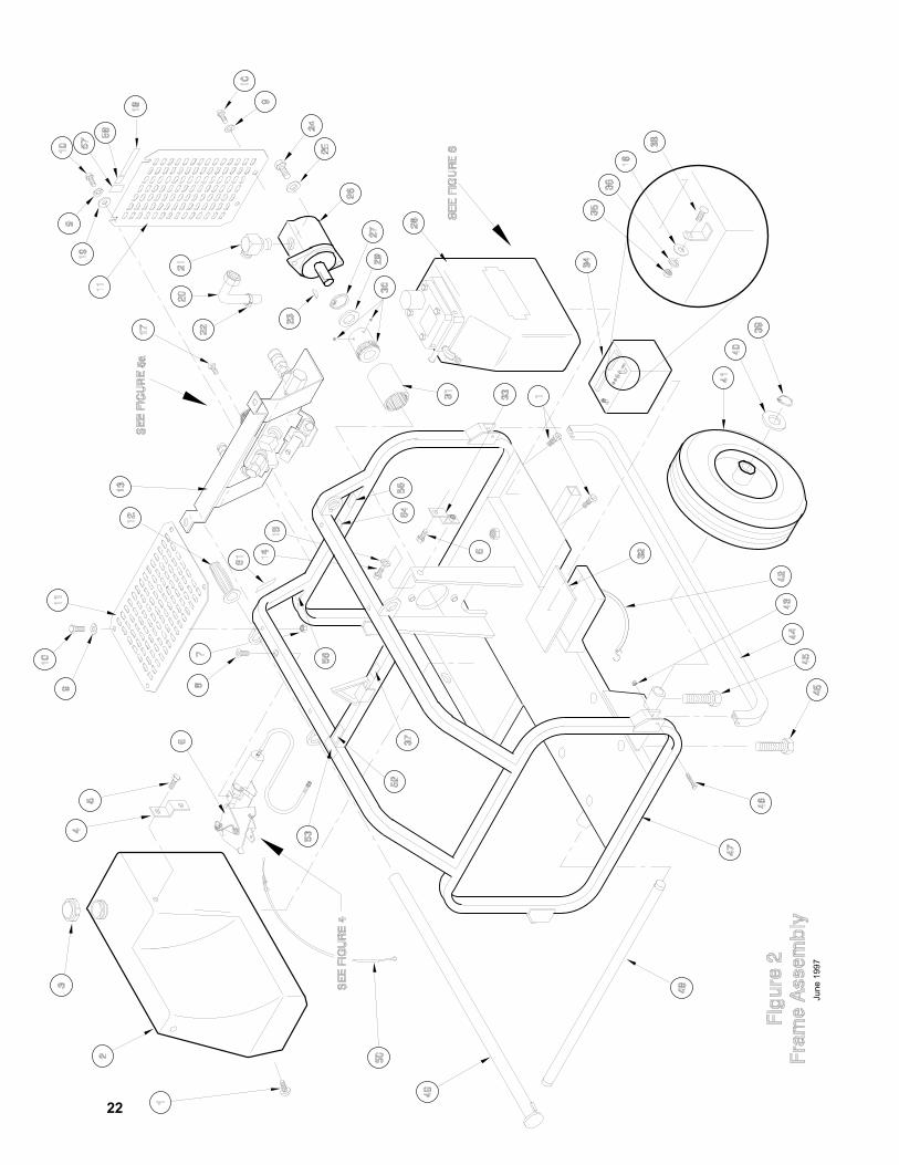
1 31241 5 Screw, 5/16 in.-18, slotted pan head2 23401 1 Fuel Tank3 07810 1 Fuel Tank Cap4 21688 1 Tank Support5 04416 2 Capscrew, 5/16 in.-18 x 1/26 23774 1 Actuator Assy (See Fig. 4)7 00719 1 Nut8 00035 1 Capscrew, 1/4 in.-20 x 1-1/49 04539 7 Washer, 1/4 in.
10 03907 8 Capscrew, 1/4 in.-20 x 1-1/211 27759 2 Top Grille12 08080 2 Handle Grip13 23775 1 Dash Panel Assy (See Fig. 5)14 02072 2 Capscrew, 5/16 in.-18 x 3/415 03031 9 Lockwasher, 5/16 in.16 12175 15 Flatwasher, 5/16 in.17 08201 2 Capscrew, 5/16 in.-18 x 1-1/218 29133 1 Proposition 65 Sticker (California)19 04530 2 Washer, 1/4 in.20 07757 4 Capscrew, 7/16 in.-14 x 1-1/221 05967 1 Inlet Flange22 08045 1 O-ring, 1-1/2 in. x 1-3/4 x 1/8 R1723 ----- 1 Key (Incld with item 26)24 07860 2 Capscrew, 3/8 in.-16 x 1-1/425 01459 2 Lockwasher, 3/8 in.26 04134 1 Hydraulic Pump27 ----- 1 Retaining Ring (Incld with item 30)28 07803 1 Hydraulic Tank Assy (See Fig. 6)29 ----- 1 Washer, (Incld with item 30)30 23719 1 Coupling Assy (Incld item 31)31 ----- 1 Coupling Sleeve (Incld with item 30)
Item P/N Qty Description No Item P/N Qty Description No
32 10499 1 Battery Pad33 07758 1 Tank Support Tab34 04303 1 Battery35 00429 2 Nut36 03031 2 Lockwasher, 5/1637 28983 1 Weight Sticker38 05227 2 Carriage Bolt, 5/16 in. x 3/439 31240 2 Retaining Ring40 01918 2 Washer41 16310 2 Wheel42 04566 1 Battery Strap43 03906 4 Nut, ESNA, 5/16 in.-1844 ----- 2 Incld with item 4745 370504 2 Capscrew, 5/16 in.-18 x 2-3/446 370513 4 Capscrew, 5/16 in.-18 x 1-3/447 28091 1 Frame Weldment48 16363 2 Axle49 28093 2 Handle50 56687 1 Throttle Cable Kit51 07764 1 Choke Pull Decal52 28985 1 Exhaust Sticker (CE models only)53 28988 1 Exhaust Fumes Sticker (CE models only)54 28323 1 CE Sticker (CE models only)55 28788 1 Manual Sticker (CE models only)56 28984 1 Fuel Sticker (CE models only)57 29036 1 Sound Power Level Sticker (CE models only)58 28786 1 Coupler Sticker (CE models only)
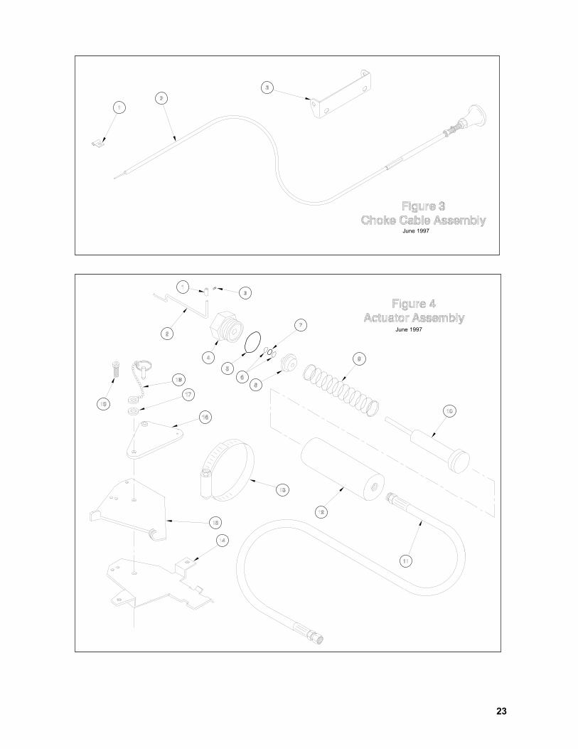
FIG.3 CHOKE CABLE ASSY - P/N 23722
1 NSS 1 Choke Cable Anchor2 NSS 1 Choke Cable Assy3 NSS 1 Bracket
FIG. 4 ACTUATOR ASSY
1 04913 1 Cable Stop2 23717 1 Cylinder Pull Wire3 ----- 1 Screw (incld with item 1)4 15161 1 Gland Cap5 06891 1 O-ring6 02838 2 Back-up Ring7 23370 1 O-ring8 15160 1 Keeper9 20550 1 Spring
10 15148 1 Piston11 360009 1 Hose Assy12 15158 1 Cylinder13 05931 1 Hose Clamp14 23785 1 Base Weldment15 23784 1 Control Weldment16 23783 1 Cylinder Lever Weldment17 04539 1 Washer, 1/4 in.18 15162 1 Fast Pin19 00769 1 Capscrew, 1/4 in.-20 x 3/4
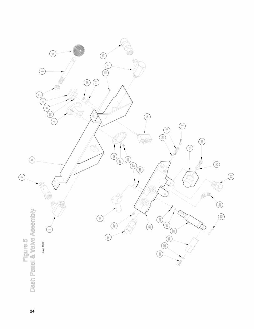
FIG. 5 DASH PANEL & VALVE ASSY
1 25633 1 Swivel Fitting2 24061 1 Male Coupler Body - 1/2 in.3 24237 1 Panel Weldment Assy (incld item 12)4 20606 1 Hour Meter5 07760 1 Spool Washer6 07820 1 Retaining Ring7 00147 1 Nut8 05849 1 Control Rod9 02633 1 Knob
10 ----- 1 Incld with item 1411 ----- 1 Incld with item 1412 07766 1 Decal13 24060 1 Female Coupler Body - 1/2 in.14 07808 1 ON/OFF Switch15 07793 1 Steel Ball16 07754 1 Spring17 01212 1 Pipe Plug18 07968 1 Starter Switch19 00899 2 Capscrew
19
Item P/N Qty Description No
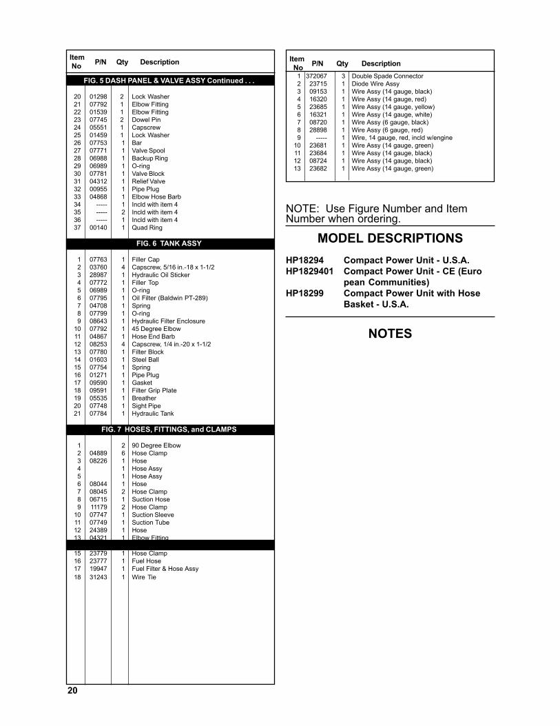
FIG. 5 DASH PANEL & VALVE ASSY Continued . . .
20 01298 2 Lock Washer21 07792 1 Elbow Fitting22 01539 1 Elbow Fitting23 07745 2 Dowel Pin24 05551 1 Capscrew25 01459 1 Lock Washer26 07753 1 Bar27 07771 1 Valve Spool28 06988 1 Backup Ring29 06989 1 O-ring30 07781 1 Valve Block31 04312 1 Relief Valve32 00955 1 Pipe Plug33 04868 1 Elbow Hose Barb34 ----- 1 Incld with item 435 ----- 2 Incld with item 436 ----- 1 Incld with item 437 00140 1 Quad Ring
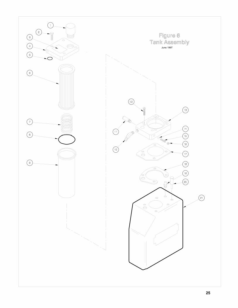
FIG. 6 TANK ASSY
1 07763 1 Filler Cap2 03760 4 Capscrew, 5/16 in.-18 x 1-1/23 28987 1 Hydraulic Oil Sticker4 07772 1 Filler Top5 06989 1 O-ring6 07795 1 Oil Filter (Baldwin PT-289)7 04708 1 Spring8 07799 1 O-ring9 08643 1 Hydraulic Filter Enclosure
10 07792 1 45 Degree Elbow11 04867 1 Hose End Barb12 08253 4 Capscrew, 1/4 in.-20 x 1-1/213 07780 1 Filter Block14 01603 1 Steel Ball15 07754 1 Spring16 01271 1 Pipe Plug17 09590 1 Gasket18 09591 1 Filter Grip Plate19 05535 1 Breather20 07748 1 Sight Pipe21 07784 1 Hydraulic Tank
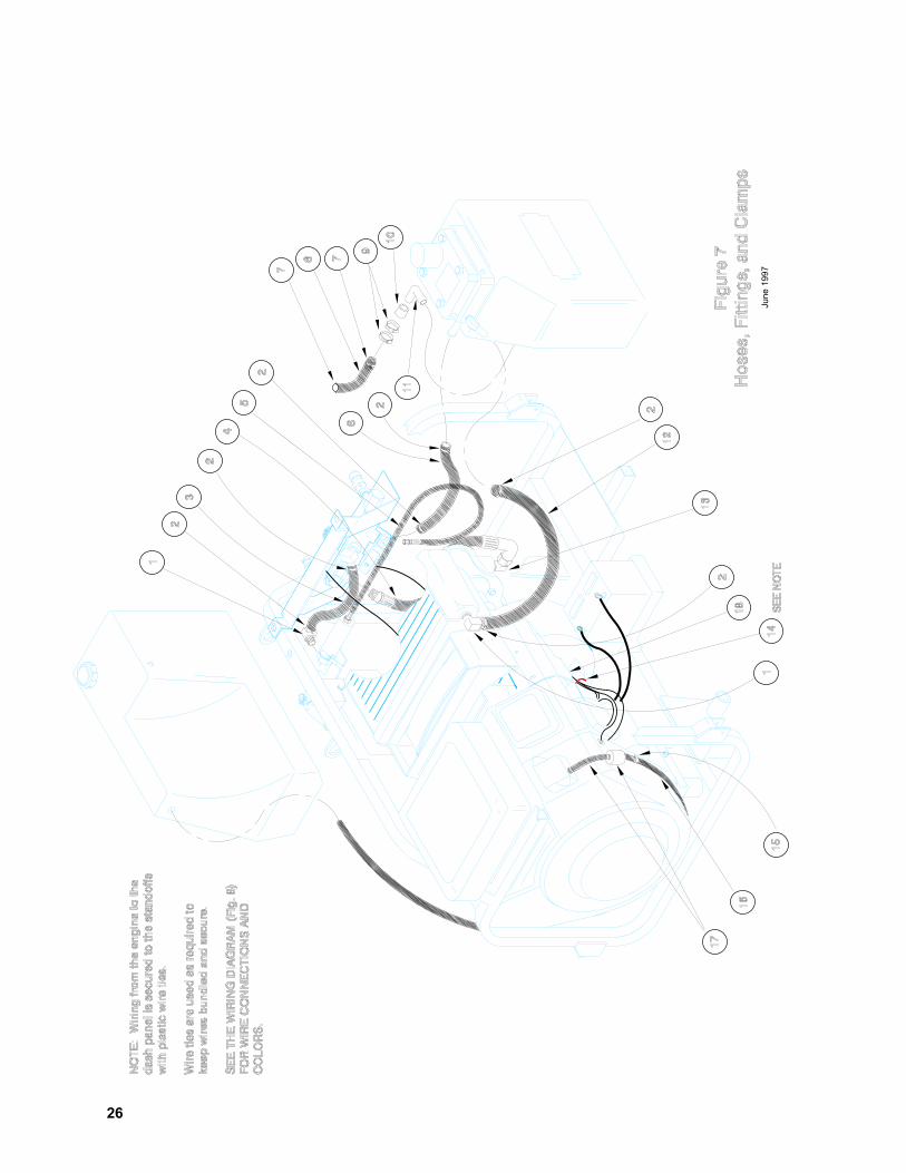
FIG. 7 HOSES, FITTINGS, and CLAMPS
1 2 90 Degree Elbow2 04889 6 Hose Clamp3 08226 1 Hose4 1 Hose Assy5 1 Hose Assy6 08044 1 Hose7 08045 2 Hose Clamp8 06715 1 Suction Hose9 11179 2 Hose Clamp
10 07747 1 Suction Sleeve11 07749 1 Suction Tube12 24389 1 Hose13 04321 1 Elbow Fitting14 31244 1 Wire Tie (as required)15 23779 1 Hose Clamp16 23777 1 Fuel Hose17 19947 1 Fuel Filter & Hose Assy18 31243 1 Wire TieIAGRAM
20
NOTE: Use Figure Number and ItemNumber when ordering.
MODEL DESCRIPTIONSHP18294 Compact Power Unit - U.S.A.HP1829401 Compact Power Unit - CE (Euro
pean Communities)HP18299 Compact Power Unit with Hose
Basket - U.S.A.
NOTES
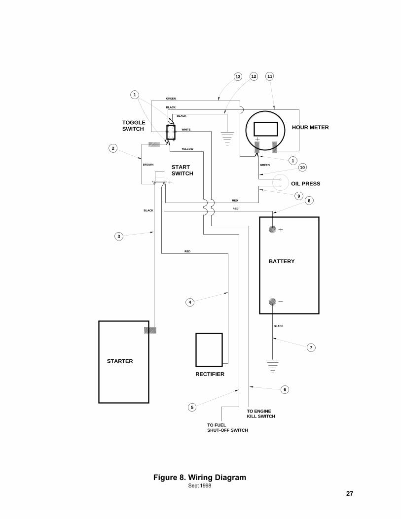
Item P/N Qty Description No1 372067 3 Double Spade Connector2 23715 1 Diode Wire Assy3 09153 1 Wire Assy (14 gauge, black)4 16320 1 Wire Assy (14 gauge, red)5 23685 1 Wire Assy (14 gauge, yellow)6 16321 1 Wire Assy (14 gauge, white)7 08720 1 Wire Assy (6 gauge, black)8 28898 1 Wire Assy (6 gauge, red)9 ----- 1 Wire, 14 gauge, red, incld w/engine
10 23681 1 Wire Assy (14 gauge, green)11 23684 1 Wire Assy (14 gauge, black)12 08724 1 Wire Assy (14 gauge, black)13 23682 1 Wire Assy (14 gauge, green)
21
June
199
7
22
June
199
7
23
June 1997
June 1997
24
June
199
7
25
June 1997
25
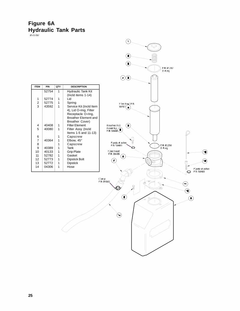
ITEM P/N QTY DESCRIPTION
52754 1 Hydraulic Tank Kit(Incld items 1-14)
1 52774 1 Lid2 52775 1 Spring3 43592 1 Service Kit (Incld Item
4), Lid O-ring, FilterReceptacle O-ring,Breather Element andBreather Cover)
4 40408 1 Filter Element5 40080 1 Filter Assy (Incld
Items 1-5 and 11-13)6 1 Capscrew7 40364 1 Elbow, 45°8 1 Capscrew9 40389 1 Tank
10 40133 1 Grip Plate11 52782 1 Gasket12 52773 1 Dipstick Bolt13 52772 1 Dipstick14 04306 1 Hose
Figure 6AHydraulic Tank Parts
26
June
199
7
TO FUELSHUT-OFF SWITCH
5TO ENGINEKILL SWITCH
6
7
4
RECTIFIER
STARTER
BATTERY
STARTSWITCH
HOUR METERTOGGLESWITCH
GREEN
BLACK
BLACK
WHITE
YELLOW
BROWN GREEN
RED
REDBLACK
RED
BLACK
3
1
2
13 12 11
1
OIL PRESS
10
98
27
Figure 8. Wiring DiagramSept 1998
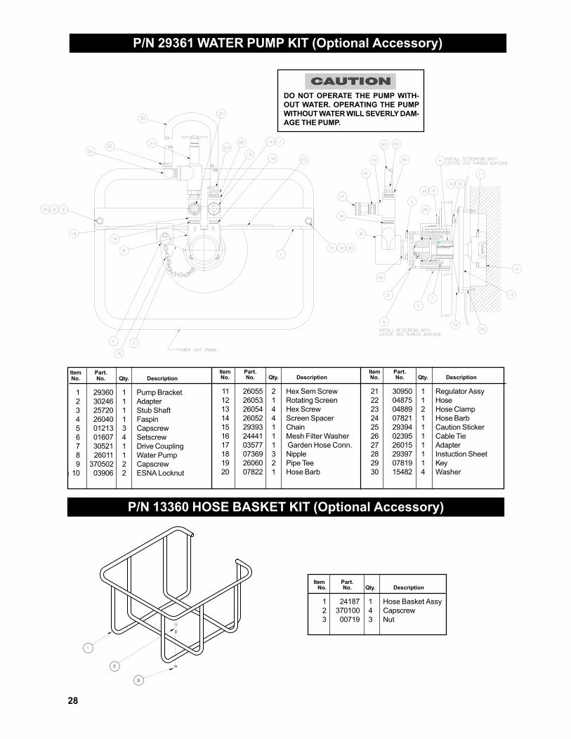
P/N 29361 WATER PUMP KIT (Optional Accessory)
Item Part.No. No. Qty. Description
1 29360 1 Pump Bracket2 30246 1 Adapter3 25720 1 Stub Shaft4 26040 1 Faspin5 01213 3 Capscrew6 01607 4 Setscrew7 30521 1 Drive Coupling8 26011 1 Water Pump9 370502 2 Capscrew
I 10 03906 2 ESNA Locknut
Item Part.No. No. Qty. Description
11 26055 2 Hex Sem Screw12 26053 1 Rotating Screen13 26054 4 Hex Screw14 26052 4 Screen Spacer15 29393 1 Chain16 24441 1 Mesh Filter Washer17 03577 1 Garden Hose Conn.18 07369 3 Nipple19 26060 2 Pipe Tee20 07822 1 Hose Barb
Item Part.No. No. Qty. Description
21 30950 1 Regulator Assy22 04875 1 Hose23 04889 2 Hose Clamp24 07821 1 Hose Barb25 29394 1 Caution Sticker26 02395 1 Cable Tie27 26015 1 Adapter28 29397 1 Instuction Sheet29 07819 1 Key30 15482 4 Washer
P/N 13360 HOSE BASKET KIT (Optional Accessory)
Item Part.No. No. Qty. Description
1 24187 1 Hose Basket Assy2 370100 4 Capscrew3 00719 3 Nut
28
DO NOT OPERATE THE PUMP WITH-OUT WATER. OPERATING THE PUMPWITHOUT WATER WILL SEVERLY DAM-AGE THE PUMP.
WARRANTYStanley Hydraulic Tools (hereinafter called “Stanley”), subject to the exceptions contained below, warrants new hydraulic tools for a period of one yearfrom the date of sale to the first retail purchaser, or for a period of 2 years from the shipping date from Stanley, whichever period expires first, to be freeof defects in material and/or workmanship at the time of delivery, and will, at its option, repair or replace any tool or part of a tool, or new part, which isfound upon examination by a Stanley authorized service outlet or by Stanley’s factory in Milwaukie, Oregon to be DEFECTIVE IN MATERIAL AND/ORWORKMANSHIP.
EXCEPTIONS FROM WARRANTY
NEW PARTS: New parts which are obtained individually are warranted, subject to the exceptions herein, to be free of defects in material and/orworkmanship at the time of delivery and for a period of 6 months after the date of first usage. Seals and diaphragms are warranted to be free of defectsin material and/or workmanship at the time of delivery and for a period of 6 months after the date of first usage or 2 years after the date of delivery,whichever period expires first. Warranty for new parts is limited to replacement of defective parts only. Labor is not covered.
FREIGHT COSTS: Freight costs to return parts to Stanley, if requested by Stanley for the purpose of evaluating a warranty claim for warranty credit, arecovered under this policy if the claimed part or parts are approved for warranty credit. Freight costs for any part or parts which are not approved forwarranty credit will be the responsibility of the individual.
SEALS & DIAPHRAGMS: Seals and diaphragms installed in new tools are warranted to be free of defects in material and/or workmanship for a periodof 6 months after the date of first usage, or for a period of 2 years from the shipping date from Stanley, whichever period expires first.
CUTTING ACCESSORIES: Cutting accessories such as breaker tool bits are warranted to be free of defects in material and or workmanship at thetime of delivery only.
ITEMS PRODUCED BY OTHER MANUFACTURERS: Components which are not manufactured by Stanley and are warranted by their respectivemanufacturers.
a. Costs incurred to remove a Stanley manufactured component in order to service an item manufactured by othermanufacturers.
ALTERATIONS & MODIFICATIONS: Alterations or modifications to any tool or part. All obligations under this warranty shall be terminated if the newtool or part is altered or modified in any way.
NORMAL WEAR: any failure or performance deficiency attributable to normal wear and tear such as tool bushings, retaining pins, wear plates,bumpers, retaining rings and plugs, rubber bushings, recoil springs, etc.
INCIDENTAL/CONSEQUENTIAL DAMAGES: To the fullest extent permitted by applicable law, in no event will STANLEY be liable for any incidental,consequential or special damages and/or expenses.
FREIGHT DAMAGE: Damage caused by improper storage or freight handling.
LOSS TIME: Loss of operating time to the user while the tool(s) is out of service.
IMPROPER OPERATION: Any failure or performance deficiency attributable to a failure to follow the guidelines and/or procedures as outlined in thetool’s operation and maintenance manual.
MAINTENANCE: Any failure or performance deficiency attributable to not maintaining the tool(s) in good operating condition as outlined in theOperation and Maintenance Manual.
HYDRAULIC PRESSURE & FLOW, HEAT, TYPE OF FLUID: Any failure or performance deficiency attributable to excess hydraulic pressure, excesshydraulic back-pressure, excess hydraulic flow, excessive heat, or incorrect hydraulic fluid.
REPAIRS OR ALTERATIONS: Any failure or performance deficiency attributable to repairs by anyone which in Stanley’s sole judgement caused orcontributed to the failure or deficiency.
MIS-APPLICATION: Any failure or performance deficiency attributable to mis-application. “Mis-application” is defined as usage of products for whichthey were not originally intended or usage of products in such a matter which exposes them to abuse or accident, without first obtaining the writtenconsent of Stanley. PERMISSION TO APPLY ANY PRODUCT FOR WHICH IT WAS NOT ORIGINALLY INTENDED CAN ONLY BE OBTAINED FROMSTANLEY ENGINEERING.
WARRANTY REGISTRATION: STANLEY ASSUMES NO LIABILITY FOR WARRANTY CLAIMS SUBMITTED FOR WHICH NO TOOL REGISTRA-TION IS ON RECORD. In the event a warranty claim is submitted and no tool registration is on record, no warranty credit will be issued without firstreceiving documentation which proves the sale of the tool or the tools’ first date of usage. The term “DOCUMENTATION” as used in this paragraph isdefined as a bill of sale, or letter of intent from the first retail customer. A WARRANTY REGISTRATION FORM THAT IS NOT ALSO ON RECORDWITH STANLEY WILL NOT BE ACCEPTED AS “DOCUMENTATION”.
NO ADDITIONAL WARRANTIES OR REPRESENTATIONS
This limited warranty and the obligation of Stanley thereunder is in lieu of all other warranties, expressed or implied including merchantability or fitnessfor a particular purpose except for that provided herein. There is no other warranty. This warranty gives the purchaser specific legal rights andother rights may be available which might vary depending upon applicable law.
29
Stanley Hydraulic ToolsDivision of the Stanley Works3810 S.E. Naef RoadMilwaukie, Oregon 97267-5698Phone: 503/659-5660Fax: 503/652-1780
NORTH AMERICA &CORPORATEHEADQUARTERS
Stanley Hydraulic Tools3810 S.E. Naef RoadMilwaukie, Oregon U.S.A. 97267-5698Tel: 503 659 5660Fax: 503 652 1780
EUROPEAN HEADQUARTERS
Stanley Hydraulic Tools3810 S.E. Naef RoadMilwaukie, Oregon U.S.A. 97267-5698Tel: 503 659 5660Fax: 503 652 1780
NORTHERN EUROPE
Stanley Svenska AbBox 1054Datavagen 51S436 22 Askim, SwedenTel: 46 31 289775Fax: 46 31 288099
SOUTHERN EUROPE
Stanley Tools S.p.A.Via Trieste 122060 Figino Serenza (Co.)ItalyTel: 39 31 785111Fax: 39 31 781766 / 781094
ASIA PACIFICHEADQUARTERS
Stanley Hydraulic Tools AsiaNo. 25 Senoke SouthWoodland East Industrial EstateJurong TownSingapore 2775Tel: 65 7522001Fax: 65 7522018Telex: RS 23945 STANLEY
AUSTRALIA-NEW ZEALANDHEADQUARTERS
Stanley Hydraulic Tools3810 S.E. Naef RoadMilwaukie, Oregon U.S.A. 97267-5698Tel: 503 659 5660Fax: 503 652 1780
CENTRAL & SOUTHAMERICA HEADQUARTERS
Stanley Hydraulic Tools3810 S.E. Naef RoadMilwaukie, Oregon U.S.A. 97267-5698Tel: 503 659 5660Fax: 503 652 1780
SALES & SERVICE DIRECTORY