Embed Size (px)
Citation preview
HP Pavilion 15 Notebook PC
Maintenance and Service Guide
© Copyright 2013 Hewlett-PackardDevelopment Company, L.P.
AMD, the AMD Arrow logo, andcombinations thereof, are trademarks ofAdvanced Micro Devices, Inc. Bluetooth is atrademark owned by its proprietor and usedby Hewlett-Packard Company under license.Intel, Core, and Pentium are U.S. registeredtrademarks of Intel Corporation. Microsoftand Windows are U.S. registeredtrademarks of Microsoft Corporation.SD Logo is a trademark of its proprietor.
The information contained herein is subjectto change without notice. The onlywarranties for HP products and services areset forth in the express warranty statementsaccompanying such products and services.Nothing herein should be construed asconstituting an additional warranty. HP shallnot be liable for technical or editorial errorsor omissions contained herein.
Second Edition: August 2013
First Edition: April 2013
Document Part Number: 718382-002
Product notice
This guide describes features that arecommon to most models. Some features maynot be available on your computer.
Not all features are available in all editionsof Windows 8. This computer may requireupgraded and/or separately purchasedhardware, drivers, and/or software to takefull advantage of Windows 8 functionality.See http://www.microsoft.com for details.
Software terms
By installing, copying, downloading, orotherwise using any software productpreinstalled on this computer, you agree tobe bound by the terms of the HP End UserLicense Agreement (EULA). If you do notaccept these license terms, your sole remedyis to return the entire unused product(hardware and software) within 14 days fora refund subject to the refund policy of yourplace of purchase.
For any further information or to request afull refund of the computer, please contactyour local point of sale (the seller).

Safety warning notice
WARNING! To reduce the possibility of heat-related injuries or of overheating the device, do notplace the device directly on your lap or obstruct the device air vents. Use the device only on a hard, flatsurface. Do not allow another hard surface, such as an adjoining optional printer, or a soft surface,such as pillows or rugs or clothing, to block airflow. Also, do not allow the AC adapter to contactthe skin or a soft surface, such as pillows or rugs or clothing, during operation. The device and the ACadapter comply with the user-accessible surface temperature limits defined by the InternationalStandard for Safety of Information Technology Equipment (IEC 60950).
iii

iv Safety warning notice
Table of contents
1 Product description ........................................................................................................... 1
2 External component identification ..................................................................................... 8
Finding your hardware and software information ......................................................................... 8Locating hardware .................................................................................................... 8Locating software ...................................................................................................... 8
Display ................................................................................................................................... 9Buttons and speakers .............................................................................................................. 10Keys ..................................................................................................................................... 11Lights .................................................................................................................................... 12TouchPad .............................................................................................................................. 13Left side ................................................................................................................................ 14Right side .............................................................................................................................. 16Bottom .................................................................................................................................. 17
3 Illustrated parts catalog .................................................................................................. 18
Service tag ............................................................................................................................ 18Computer major components ................................................................................................... 20Display assembly subcomponents ............................................................................................. 28Mass storage devices ............................................................................................................. 29Miscellaneous parts ................................................................................................................ 30Sequential part number listing .................................................................................................. 31
4 Removal and replacement procedures preliminary requirements .................................... 40
Tools required ....................................................................................................................... 40Service considerations ............................................................................................................ 40
Plastic parts ............................................................................................................ 40Cables and connectors ............................................................................................ 41Drive handling ........................................................................................................ 41
Grounding guidelines ............................................................................................................. 42Electrostatic discharge damage ................................................................................. 42
v
Packaging and transporting guidelines ....................................................... 43Workstation guidelines .............................................................. 43
5 Removal and replacement procedures for Customer Self-Repair parts ............................. 45
Component replacement procedures ........................................................................................ 45Battery ................................................................................................................... 46Optical drive .......................................................................................................... 47Hard drive ............................................................................................................. 49WLAN module ........................................................................................................ 51Memory module ...................................................................................................... 53
6 Removal and replacement procedures for Authorized Service Provider parts .................. 55
Component replacement procedures ........................................................................................ 55Keyboard ............................................................................................................... 56Top cover ............................................................................................................... 60Power button board ................................................................................................. 64TouchPad button board ............................................................................................ 65Display assembly subcomponents .............................................................................. 66System board ......................................................................................................... 74Fan ....................................................................................................................... 79Heat sink ............................................................................................................... 80Processor ............................................................................................................... 85PCH heat sink ......................................................................................................... 87RTC battery ............................................................................................................ 89RJ-45/USB board .................................................................................................... 91Power connector cable ............................................................................................ 92Speakers ................................................................................................................ 94Optical drive connector cable ................................................................................... 96
7 Using Setup Utility (BIOS) and System Diagnostics ........................................................... 98
Starting Setup Utility (BIOS) ..................................................................................................... 98Updating the BIOS ................................................................................................................. 98
Determining the BIOS version ................................................................................... 98Downloading a BIOS update .................................................................................... 99
Using System Diagnostics ...................................................................................................... 100
8 Specifications ................................................................................................................ 101
Computer specifications ........................................................................................................ 10115.6-inch display specifications ............................................................................................. 102Hard drive specifications ...................................................................................................... 103
vi
Hard drive specifications (continued) ...................................................................................... 104
9 Backing up, restoring, and recovering .......................................................................... 105
Creating recovery media and backups ................................................................................... 106Creating HP Recovery media .................................................................................. 107
Restore and recovery ............................................................................................................ 108Using Windows Refresh for quick and easy recovery ................................................. 109Remove everything and reinstall Windows ............................................................... 109Recovering using HP Recovery Manager .................................................................. 110
What you need to know .......................................................................... 110Using the HP Recovery partition to recover a minimized image(select models only) ................................................................................ 111Using HP Recovery media to recover ........................................................ 111Changing the computer boot order ........................................................... 111
Removing the HP Recovery partition ........................................................................ 112
10 Power cord set requirements ...................................................................................... 113
Requirements for all countries ................................................................................................ 113Requirements for specific countries and regions ....................................................................... 114
11 Recycling .................................................................................................................... 115
Index ............................................................................................................................... 116
vii

viii
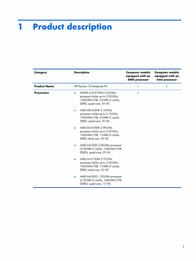
1 Product description
Category Description Computer modelsequipped with an
AMD processor
Computer modelsequipped with an
Intel processor
Product Name HP Pavilion 15 Notebook PC √ √
Processors ● AMD® A10-5750M 2.50-GHzprocessor (turbo up to 3.50-GHz;1600-MHz FSB, 4.0-MB L2 cache,DDR3, quad core, 35 W)
● AMD A8-5550M 2.10-GHzprocessor (turbo up to 3.10-GHz;1600-MHz FSB, 4.0-MB L2 cache,DDR3, quad core, 35 W)
● AMD A6-5350M 2.90-GHzprocessor (turbo up to 3.50-GHz;1600-MHz FSB, 1.0-MB L2 cache,DDR3, dual core, 35 W)
● AMD A6-5200 2.00-GHz processor(2.00-MB L2 cache, 1600-MHz FSB,DDR3L, quad core, 25 W)
● AMD A4-5150M 2.70-GHzprocessor (turbo up to 3.30-GHz;1600-MHz FSB, 1.0-MB L2 cache,DDR3, dual core, 35 W)
● AMD A4-5000 1.50-GHz processor(2.00-MB L2 cache, 1600-MHz FSB,DDR3L, quad core, 15 W)
√
1
Category Description Computer modelsequipped with an
AMD processor
Computer modelsequipped with an
Intel processor
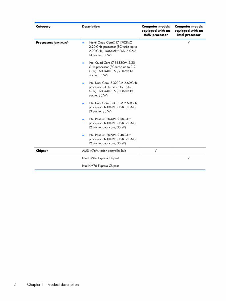
Processors (continued) ● Intel® Quad Core® i7-4702MQ2.20-GHz processor (SC turbo up to2.90-GHz; 1600-MHz FSB, 6.0-MBL3 cache, 37 W)
● Intel Quad Core i7-3632QM 2.20-GHz processor (SC turbo up to 3.2-GHz; 1600-MHz FSB, 6.0-MB L3cache, 35 W)
● Intel Dual Core i5-3230M 2.60-GHzprocessor (SC turbo up to 3.20-GHz; 1600-MHz FSB, 3.0-MB L3cache, 35 W)
● Intel Dual Core i3-3130M 2.60-GHzprocessor (1600-MHz FSB, 3.0-MBL3 cache, 35 W)
● Intel Pentium 2030M 2.50-GHzprocessor (1600-MHz FSB, 2.0-MBL2 cache, dual core, 35 W)
● Intel Pentium 2020M 2.40-GHzprocessor (1600-MHz FSB, 2.0-MBL2 cache, dual core, 35 W)
√
Chipset AMD A76M fusion controller hub √
Intel HM86 Express Chipset
Intel HM76 Express Chipset
√
2 Chapter 1 Product description
Category Description Computer modelsequipped with an
AMD processor
Computer modelsequipped with an
Intel processor
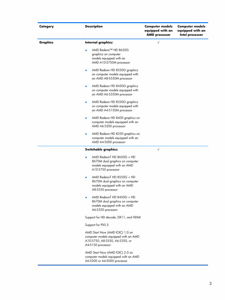
Graphics Internal graphics:
● AMD Radeon™ HD 8650Ggraphics on computermodels equipped with anAMD A10-5750M processor
● AMD Radeon HD 8550G graphicson computer models equipped withan AMD A8-5550M processor
● AMD Radeon HD 8450G graphicson computer models equipped withan AMD A6-5350M processor
● AMD Radeon HD 8350G graphicson computer models equipped withan AMD A4-5150M processor
● AMD Radeon HD 8400 graphics oncomputer models equipped with anAMD A6-5200 processor
● AMD Radeon HD 8330 graphics oncomputer models equipped with anAMD A4-5000 processor
√
Switchable graphics:
● AMD RadeonT HD 8650G + HD8670M dual graphics on computermodels equipped with an AMDA10-5750 processor
● AMD RadeonT HD 8550G + HD8670M dual graphics on computermodels equipped with an AMDA8-5550 processor
● AMD RadeonT HD 8450G + HD8670M dual graphics on computermodels equipped with an AMDA6-5350 processor
Support for HD decode, DX11, and HDMI
Support for PX5.5
AMD Start Now (AMD IOIC) 1.0 oncomputer models equipped with an AMDA10-5750, A8-5550, A6-5350, orA4-5150 processor
AMD Start Now (AMD IOIC) 2.0 oncomputer models equipped with an AMDA6-5200 or A4-5000 processor
√
3
Category Description Computer modelsequipped with an
AMD processor
Computer modelsequipped with an
Intel processor
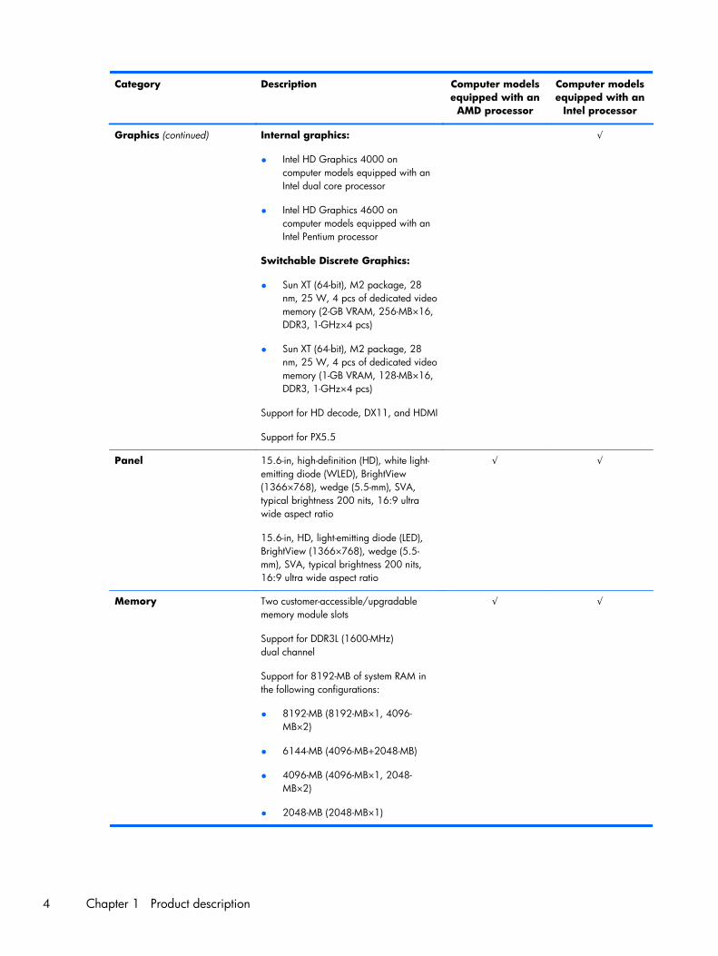
Graphics (continued) Internal graphics:
● Intel HD Graphics 4000 oncomputer models equipped with anIntel dual core processor
● Intel HD Graphics 4600 oncomputer models equipped with anIntel Pentium processor
Switchable Discrete Graphics:
● Sun XT (64-bit), M2 package, 28nm, 25 W, 4 pcs of dedicated videomemory (2-GB VRAM, 256-MB×16,DDR3, 1-GHz×4 pcs)
● Sun XT (64-bit), M2 package, 28nm, 25 W, 4 pcs of dedicated videomemory (1-GB VRAM, 128-MB×16,DDR3, 1-GHz×4 pcs)
Support for HD decode, DX11, and HDMI
Support for PX5.5
√
Panel 15.6-in, high-definition (HD), white light-emitting diode (WLED), BrightView(1366×768), wedge (5.5-mm), SVA,typical brightness 200 nits, 16:9 ultrawide aspect ratio
15.6-in, HD, light-emitting diode (LED),BrightView (1366×768), wedge (5.5-mm), SVA, typical brightness 200 nits,16:9 ultra wide aspect ratio
√ √
Memory Two customer-accessible/upgradablememory module slots
Support for DDR3L (1600-MHz)dual channel
Support for 8192-MB of system RAM inthe following configurations:
● 8192-MB (8192-MB×1, 4096-MB×2)
● 6144-MB (4096-MB+2048-MB)
● 4096-MB (4096-MB×1, 2048-MB×2)
● 2048-MB (2048-MB×1)
√ √
4 Chapter 1 Product description
Category Description Computer modelsequipped with an
AMD processor
Computer modelsequipped with an
Intel processor
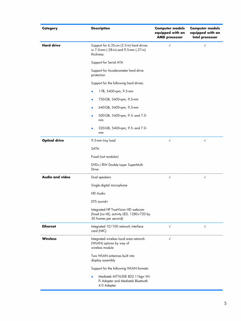
Hard drive Support for 6.35-cm (2.5-in) hard drivesin 7.0-mm (.28-in) and 9.5-mm (.37-in)thickness
Support for Serial ATA
Support for Accelerometer hard driveprotection
Support for the following hard drives:
● 1-TB, 5400-rpm, 9.5-mm
● 750-GB, 5400-rpm, 9.5-mm
● 640-GB, 5400-rpm, 9.5-mm
● 500-GB, 5400-rpm, 9.5- and 7.0-mm
● 320-GB, 5400-rpm, 9.5- and 7.0-mm
√ √
Optical drive 9.5-mm tray load
SATA
Fixed (not modular)
DVD+/-RW Double Layer SuperMultiDrive
√ √
Audio and video Dual speakers
Single digital microphone
HD Audio
DTS sound+
Integrated HP TrueVision HD webcam(fixed [no tilt], activity LED, 1280×720 by30 frames per second)
√ √
Ethernet Integrated 10/100 network interfacecard (NIC)
√ √
Wireless Integrated wireless local area network(WLAN) options by way ofwireless module
Two WLAN antennas built intodisplay assembly
Support for the following WLAN formats:
● Mediatek MT7630E 802.11bgn Wi-Fi Adapter and Mediatek Bluetooth4.0 Adapter
√
5
Category Description Computer modelsequipped with an
AMD processor
Computer modelsequipped with an
Intel processor
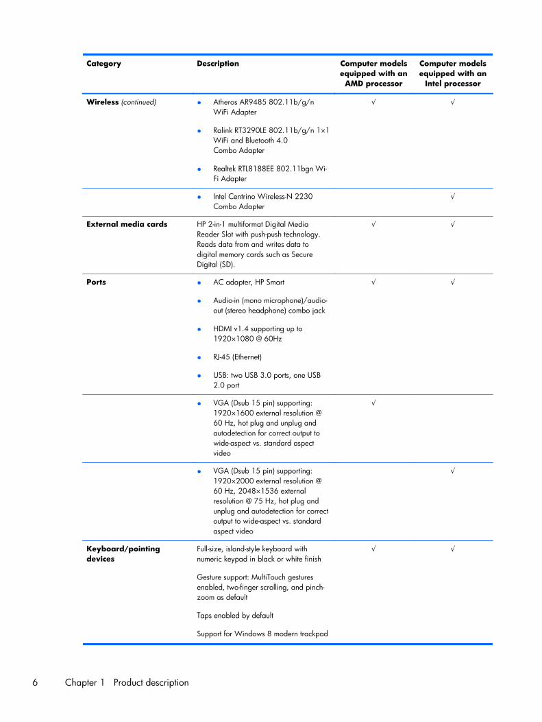
Wireless (continued) ● Atheros AR9485 802.11b/g/nWiFi Adapter
● Ralink RT3290LE 802.11b/g/n 1×1WiFi and Bluetooth 4.0Combo Adapter
● Realtek RTL8188EE 802.11bgn Wi-Fi Adapter
√ √
● Intel Centrino Wireless-N 2230Combo Adapter
√
External media cards HP 2-in-1 multiformat Digital MediaReader Slot with push-push technology.Reads data from and writes data todigital memory cards such as SecureDigital (SD).
√ √
Ports ● AC adapter, HP Smart
● Audio-in (mono microphone)/audio-out (stereo headphone) combo jack
● HDMI v1.4 supporting up to1920×1080 @ 60Hz
● RJ-45 (Ethernet)
● USB: two USB 3.0 ports, one USB2.0 port
√ √
● VGA (Dsub 15 pin) supporting:1920×1600 external resolution @60 Hz, hot plug and unplug andautodetection for correct output towide-aspect vs. standard aspectvideo
√
● VGA (Dsub 15 pin) supporting:1920×2000 external resolution @60 Hz, 2048×1536 externalresolution @ 75 Hz, hot plug andunplug and autodetection for correctoutput to wide-aspect vs. standardaspect video
√
Keyboard/pointingdevices
Full-size, island-style keyboard withnumeric keypad in black or white finish
Gesture support: MultiTouch gesturesenabled, two-finger scrolling, and pinch-zoom as default
Taps enabled by default
Support for Windows 8 modern trackpad
√ √
6 Chapter 1 Product description
Category Description Computer modelsequipped with an
AMD processor
Computer modelsequipped with an
Intel processor
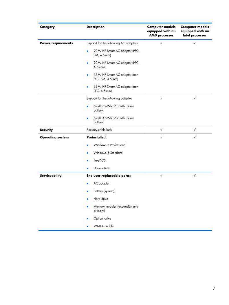
Power requirements Support for the following AC adapters:
● 90-W HP Smart AC adapter (PFC,EM, 4.5-mm)
● 90-W HP Smart AC adapter (PFC,4.5-mm)
● 65-W HP Smart AC adapter (non-PFC, EM, 4.5-mm)
● 65-W HP Smart AC adapter (non-PFC, 4.5-mm)
√ √
Support for the following batteries
● 6-cell, 62-Wh, 2.80-Ah, Li-ionbattery
● 6-cell, 47-Wh, 2.20-Ah, Li-ionbattery
√ √
Security Security cable lock √ √
Operating system Preinstalled:
● Windows 8 Professional
● Windows 8 Standard
● FreeDOS
● Ubuntu Linux
√ √
Serviceability End user replaceable parts:
● AC adapter
● Battery (system)
● Hard drive
● Memory modules (expansion andprimary)
● Optical drive
● WLAN module
√ √
7
2 External component identification
Finding your hardware and software information
Locating hardware
To find out what hardware is installed on your computer:
1. From the Start screen, type c, and then select Control Panel.
2. Select System and Security, and then in the System area, click Device Manager.
A list reveals all the devices installed in your computer.
Locating software
▲ To find out what software is installed on your computer, from the Start screen, right-click usingthe mouse or swipe from the top of the TouchPad to reveal the apps and then select theAll apps icon.
8 Chapter 2 External component identification
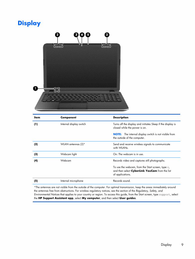
Display
Item Component Description
(1) Internal display switch Turns off the display and initiates Sleep if the display isclosed while the power is on.
NOTE: The internal display switch is not visible fromthe outside of the computer.
(2) WLAN antennas (2)* Send and receive wireless signals to communicatewith WLANs.
(3) Webcam light On: The webcam is in use.
(4) Webcam Records video and captures still photographs.
To use the webcam, from the Start screen, type c,and then select CyberLink YouCam from the listof applications.
(5) Internal microphone Records sound.
*The antennas are not visible from the outside of the computer. For optimal transmission, keep the areas immediately aroundthe antennas free from obstructions. For wireless regulatory notices, see the section of the Regulatory, Safety, andEnvironmental Notices that applies to your country or region. To access this guide, from the Start screen, type support, selectthe HP Support Assistant app, select My computer, and then select User guides.
Display 9
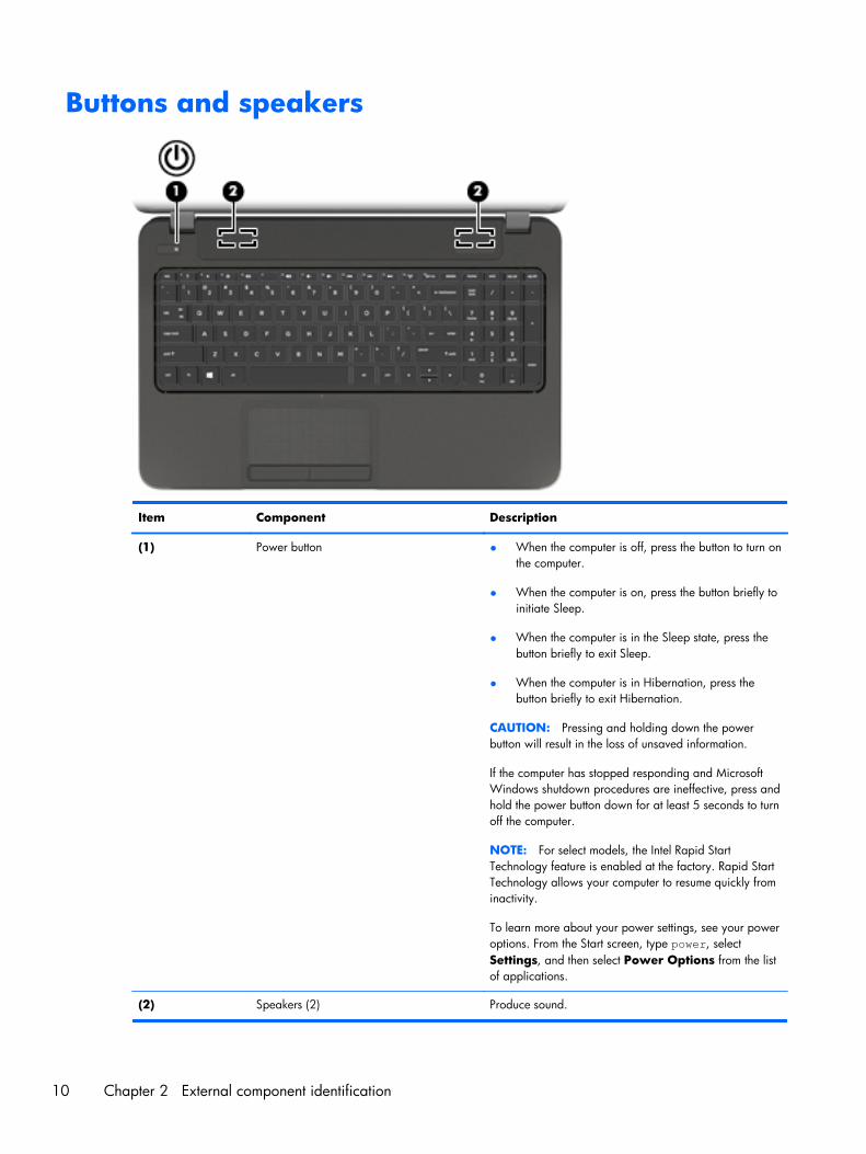
Buttons and speakers
Item Component Description
(1) Power button ● When the computer is off, press the button to turn onthe computer.
● When the computer is on, press the button briefly toinitiate Sleep.
● When the computer is in the Sleep state, press thebutton briefly to exit Sleep.
● When the computer is in Hibernation, press thebutton briefly to exit Hibernation.
CAUTION: Pressing and holding down the powerbutton will result in the loss of unsaved information.
If the computer has stopped responding and MicrosoftWindows shutdown procedures are ineffective, press andhold the power button down for at least 5 seconds to turnoff the computer.
NOTE: For select models, the Intel Rapid StartTechnology feature is enabled at the factory. Rapid StartTechnology allows your computer to resume quickly frominactivity.
To learn more about your power settings, see your poweroptions. From the Start screen, type power, selectSettings, and then select Power Options from the listof applications.
(2) Speakers (2) Produce sound.
10 Chapter 2 External component identification
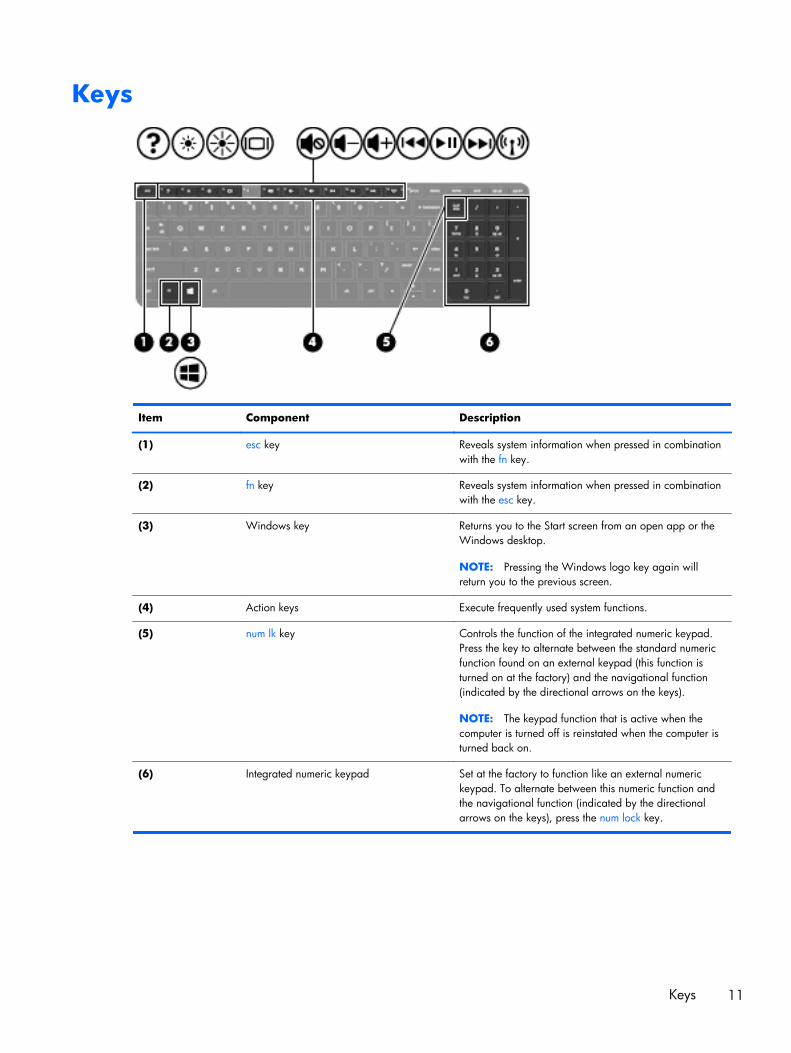
Keys
Item Component Description
(1) esc key Reveals system information when pressed in combinationwith the fn key.
(2) fn key Reveals system information when pressed in combinationwith the esc key.
(3) Windows key Returns you to the Start screen from an open app or theWindows desktop.
NOTE: Pressing the Windows logo key again willreturn you to the previous screen.
(4) Action keys Execute frequently used system functions.
(5) num lk key Controls the function of the integrated numeric keypad.Press the key to alternate between the standard numericfunction found on an external keypad (this function isturned on at the factory) and the navigational function(indicated by the directional arrows on the keys).
NOTE: The keypad function that is active when thecomputer is turned off is reinstated when the computer isturned back on.
(6) Integrated numeric keypad Set at the factory to function like an external numerickeypad. To alternate between this numeric function andthe navigational function (indicated by the directionalarrows on the keys), press the num lock key.
Keys 11
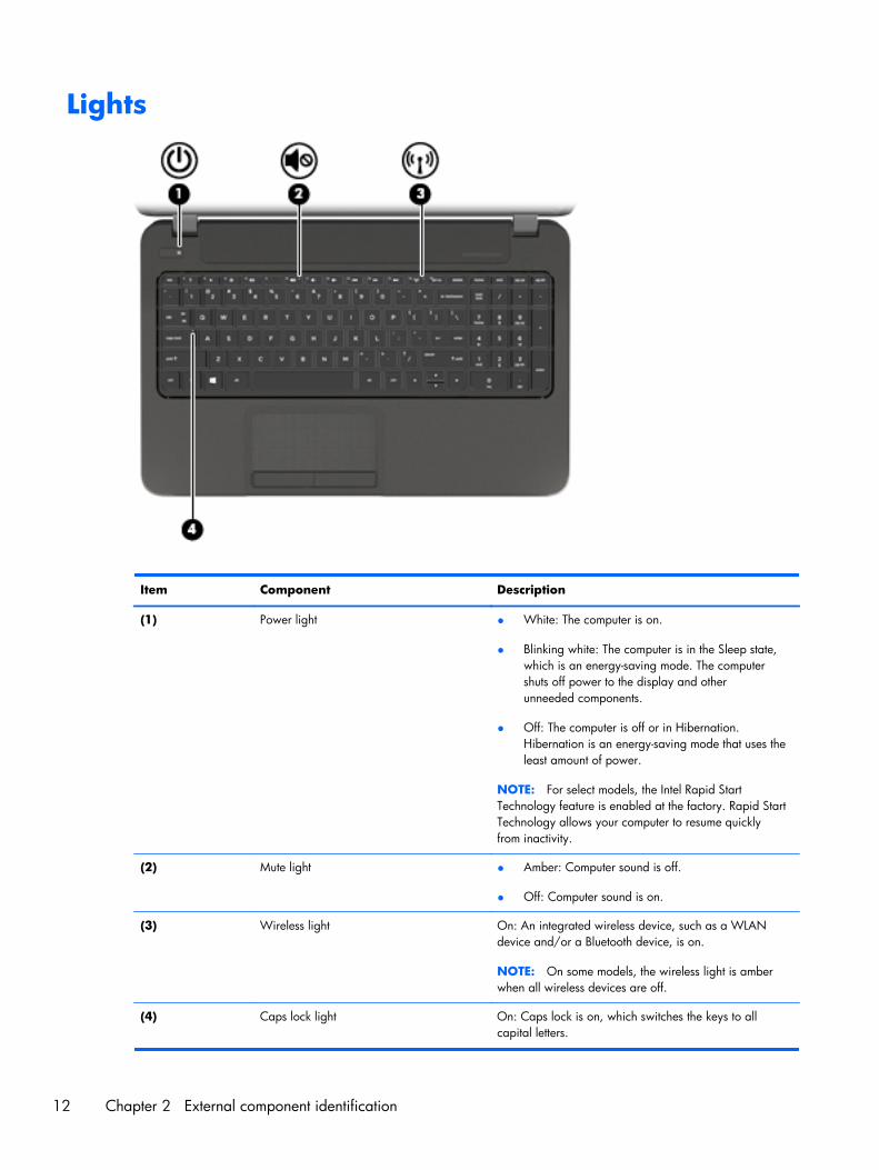
Lights
Item Component Description
(1) Power light ● White: The computer is on.
● Blinking white: The computer is in the Sleep state,which is an energy-saving mode. The computershuts off power to the display and otherunneeded components.
● Off: The computer is off or in Hibernation.Hibernation is an energy-saving mode that uses theleast amount of power.
NOTE: For select models, the Intel Rapid StartTechnology feature is enabled at the factory. Rapid StartTechnology allows your computer to resume quicklyfrom inactivity.
(2) Mute light ● Amber: Computer sound is off.
● Off: Computer sound is on.
(3) Wireless light On: An integrated wireless device, such as a WLANdevice and/or a Bluetooth device, is on.
NOTE: On some models, the wireless light is amberwhen all wireless devices are off.
(4) Caps lock light On: Caps lock is on, which switches the keys to allcapital letters.
12 Chapter 2 External component identification
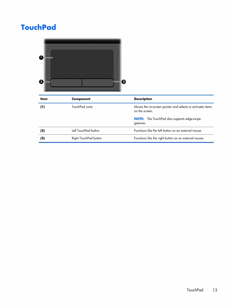
TouchPad
Item Component Description
(1) TouchPad zone Moves the on-screen pointer and selects or activates itemson the screen.
NOTE: The TouchPad also supports edge-swipegestures.
(2) Left TouchPad button Functions like the left button on an external mouse.
(3) Right TouchPad button Functions like the right button on an external mouse.
TouchPad 13
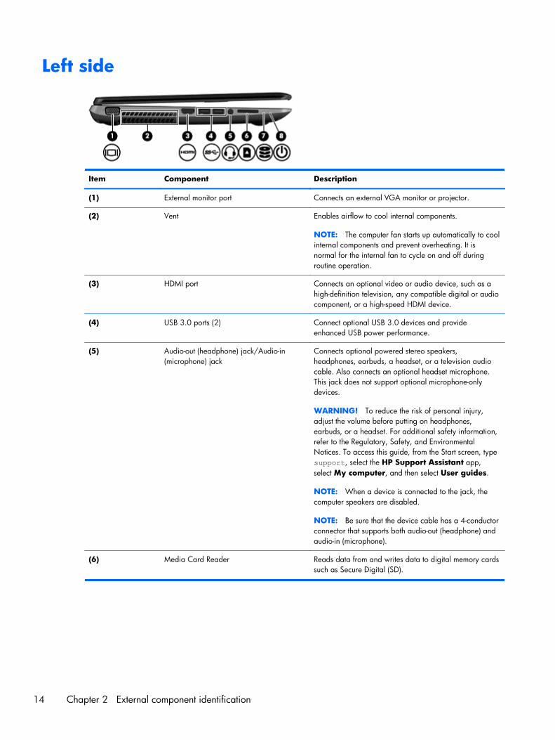
Left side
Item Component Description
(1) External monitor port Connects an external VGA monitor or projector.
(2) Vent Enables airflow to cool internal components.
NOTE: The computer fan starts up automatically to coolinternal components and prevent overheating. It isnormal for the internal fan to cycle on and off duringroutine operation.
(3) HDMI port Connects an optional video or audio device, such as ahigh-definition television, any compatible digital or audiocomponent, or a high-speed HDMI device.
(4) USB 3.0 ports (2) Connect optional USB 3.0 devices and provideenhanced USB power performance.
(5) Audio-out (headphone) jack/Audio-in(microphone) jack
Connects optional powered stereo speakers,headphones, earbuds, a headset, or a television audiocable. Also connects an optional headset microphone.This jack does not support optional microphone-onlydevices.
WARNING! To reduce the risk of personal injury,adjust the volume before putting on headphones,earbuds, or a headset. For additional safety information,refer to the Regulatory, Safety, and EnvironmentalNotices. To access this guide, from the Start screen, typesupport, select the HP Support Assistant app,select My computer, and then select User guides.
NOTE: When a device is connected to the jack, thecomputer speakers are disabled.
NOTE: Be sure that the device cable has a 4-conductorconnector that supports both audio-out (headphone) andaudio-in (microphone).
(6) Media Card Reader Reads data from and writes data to digital memory cardssuch as Secure Digital (SD).
14 Chapter 2 External component identification
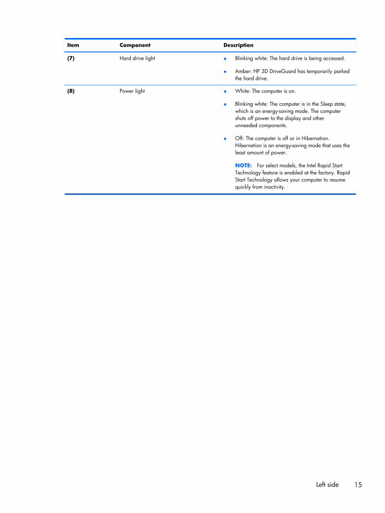
Item Component Description
(7) Hard drive light ● Blinking white: The hard drive is being accessed.
● Amber: HP 3D DriveGuard has temporarily parkedthe hard drive.
(8) Power light ● White: The computer is on.
● Blinking white: The computer is in the Sleep state,which is an energy-saving mode. The computershuts off power to the display and otherunneeded components.
● Off: The computer is off or in Hibernation.Hibernation is an energy-saving mode that uses theleast amount of power.
NOTE: For select models, the Intel Rapid StartTechnology feature is enabled at the factory. RapidStart Technology allows your computer to resumequickly from inactivity.
Left side 15
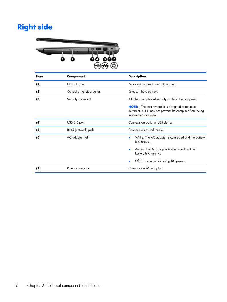
Right side
Item Component Description
(1) Optical drive Reads and writes to an optical disc.
(2) Optical drive eject button Releases the disc tray.
(3) Security cable slot Attaches an optional security cable to the computer.
NOTE: The security cable is designed to act as adeterrent, but it may not prevent the computer from beingmishandled or stolen.
(4) USB 2.0 port Connects an optional USB device.
(5) RJ-45 (network) jack Connects a network cable.
(6) AC adapter light ● White: The AC adapter is connected and the batteryis charged.
● Amber: The AC adapter is connected and thebattery is charging.
● Off: The computer is using DC power.
(7) Power connector Connects an AC adapter.
16 Chapter 2 External component identification
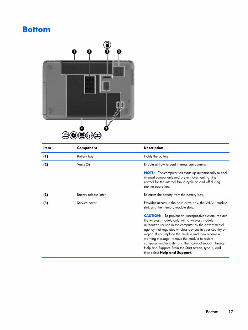
Bottom
Item Component Description
(1) Battery bay Holds the battery.
(2) Vents (5) Enable airflow to cool internal components.
NOTE: The computer fan starts up automatically to coolinternal components and prevent overheating. It isnormal for the internal fan to cycle on and off duringroutine operation.
(3) Battery release latch Releases the battery from the battery bay.
(4) Service cover Provides access to the hard drive bay, the WLAN moduleslot, and the memory module slots.
CAUTION: To prevent an unresponsive system, replacethe wireless module only with a wireless moduleauthorized for use in the computer by the governmentalagency that regulates wireless devices in your country orregion. If you replace the module and then receive awarning message, remove the module to restorecomputer functionality, and then contact support throughHelp and Support. From the Start screen, type h, andthen select Help and Support.
Bottom 17
3 Illustrated parts catalog
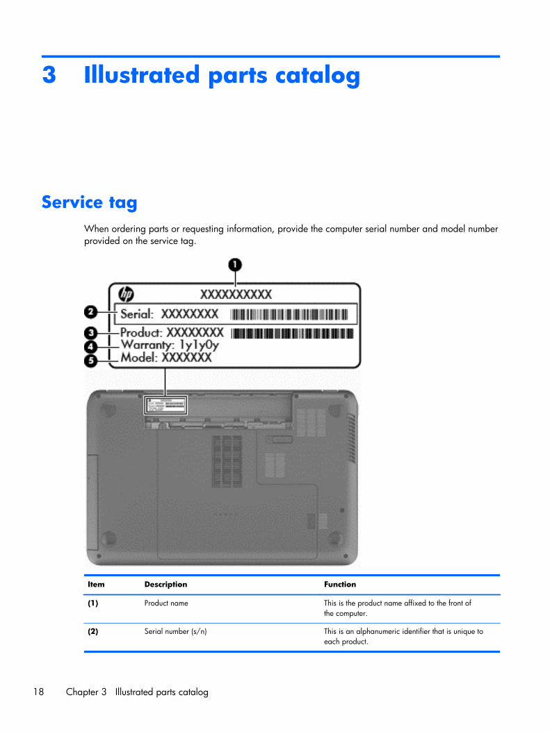
Service tagWhen ordering parts or requesting information, provide the computer serial number and model numberprovided on the service tag.
Item Description Function
(1) Product name This is the product name affixed to the front ofthe computer.
(2) Serial number (s/n) This is an alphanumeric identifier that is unique toeach product.
18 Chapter 3 Illustrated parts catalog
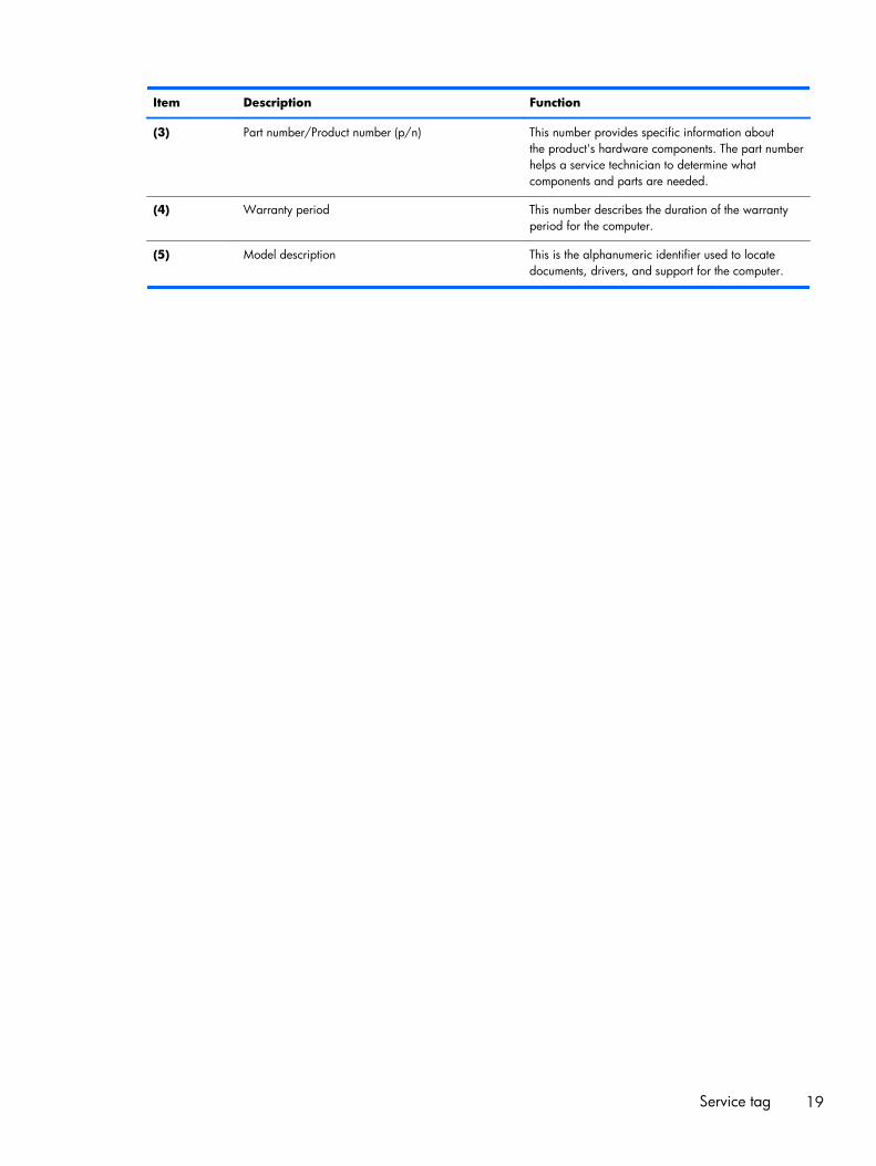
Item Description Function
(3) Part number/Product number (p/n) This number provides specific information aboutthe product's hardware components. The part numberhelps a service technician to determine whatcomponents and parts are needed.
(4) Warranty period This number describes the duration of the warrantyperiod for the computer.
(5) Model description This is the alphanumeric identifier used to locatedocuments, drivers, and support for the computer.
Service tag 19
Computer major components
20 Chapter 3 Illustrated parts catalog
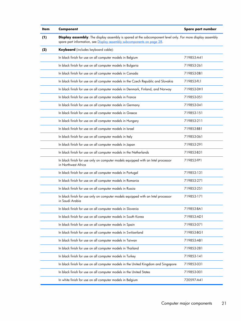
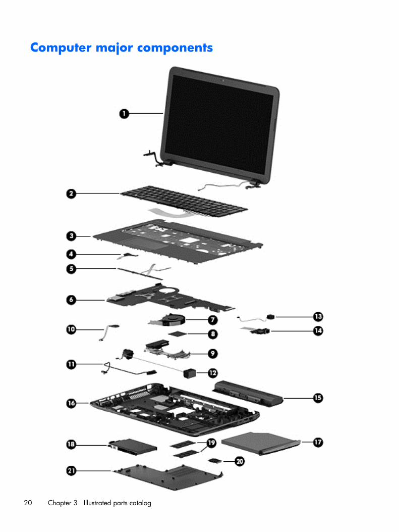
Item Component Spare part number
(1) Display assembly: The display assembly is spared at the subcomponent level only. For more display assemblyspare part information, see Display assembly subcomponents on page 28.
(2) Keyboard (includes keyboard cable):
In black finish for use on all computer models in Belgium 719853-A41
In black finish for use on all computer models in Bulgaria 719853-261
In black finish for use on all computer models in Canada 719853-DB1
In black finish for use on all computer models in the Czech Republic and Slovakia 719853-FL1
In black finish for use on all computer models in Denmark, Finland, and Norway 719853-DH1
In black finish for use on all computer models in France 719853-051
In black finish for use on all computer models in Germany 719853-041
In black finish for use on all computer models in Greece 719853-151
In black finish for use on all computer models in Hungary 719853-211
In black finish for use on all computer models in Israel 719853-BB1
In black finish for use on all computer models in Italy 719853-061
In black finish for use on all computer models in Japan 719853-291
In black finish for use on all computer models in the Netherlands 719853-B31
In black finish for use only on computer models equipped with an Intel processorin Northwest Africa
719853-FP1
In black finish for use on all computer models in Portugal 719853-131
In black finish for use on all computer models in Romania 719853-271
In black finish for use on all computer models in Russia 719853-251
In black finish for use only on computer models equipped with an Intel processorin Saudi Arabia
719853-171
In black finish for use on all computer models in Slovenia 719853-BA1
In black finish for use on all computer models in South Korea 719853-AD1
In black finish for use on all computer models in Spain 719853-071
In black finish for use on all computer models in Switzerland 719853-BG1
In black finish for use on all computer models in Taiwan 719853-AB1
In black finish for use on all computer models in Thailand 719853-281
In black finish for use on all computer models in Turkey 719853-141
In black finish for use on all computer models in the United Kingdom and Singapore 719853-031
In black finish for use on all computer models in the United States 719853-001
In white finish for use on all computer models in Belgium 720597-A41
Computer major components 21
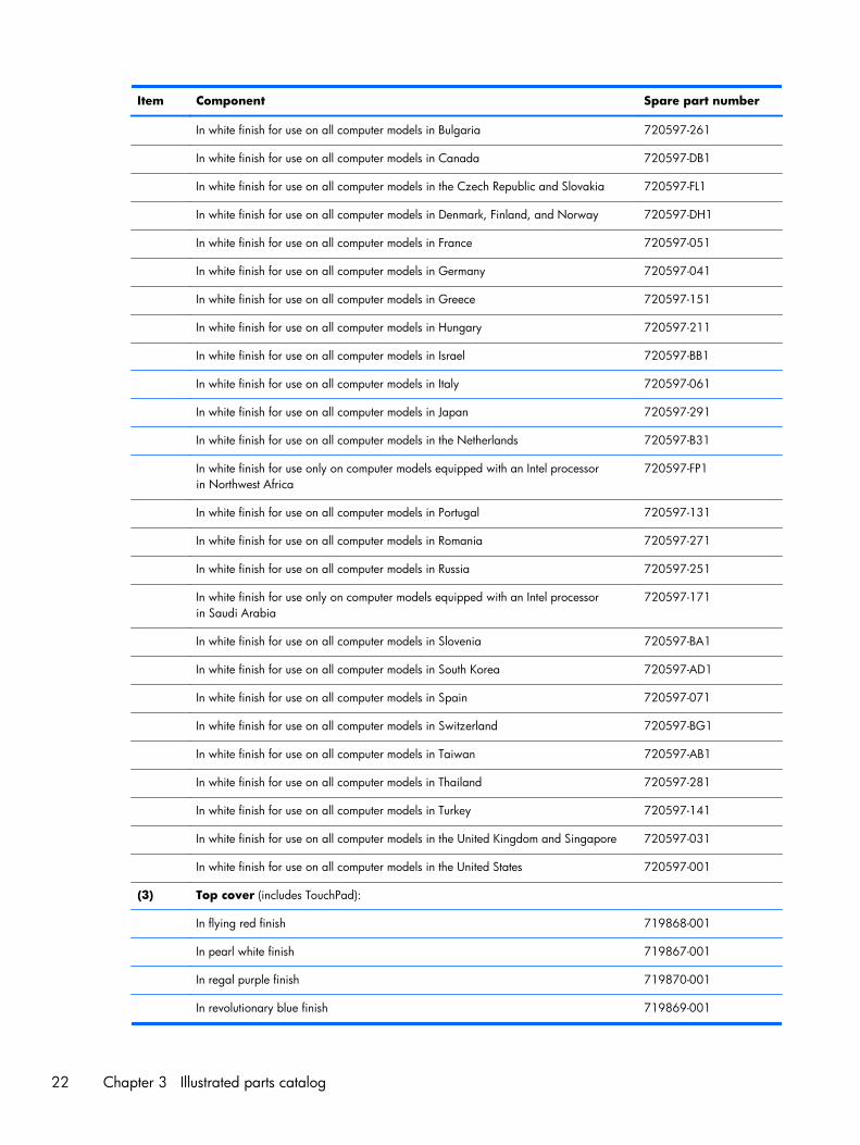
Item Component Spare part number
In white finish for use on all computer models in Bulgaria 720597-261
In white finish for use on all computer models in Canada 720597-DB1
In white finish for use on all computer models in the Czech Republic and Slovakia 720597-FL1
In white finish for use on all computer models in Denmark, Finland, and Norway 720597-DH1
In white finish for use on all computer models in France 720597-051
In white finish for use on all computer models in Germany 720597-041
In white finish for use on all computer models in Greece 720597-151
In white finish for use on all computer models in Hungary 720597-211
In white finish for use on all computer models in Israel 720597-BB1
In white finish for use on all computer models in Italy 720597-061
In white finish for use on all computer models in Japan 720597-291
In white finish for use on all computer models in the Netherlands 720597-B31
In white finish for use only on computer models equipped with an Intel processorin Northwest Africa
720597-FP1
In white finish for use on all computer models in Portugal 720597-131
In white finish for use on all computer models in Romania 720597-271
In white finish for use on all computer models in Russia 720597-251
In white finish for use only on computer models equipped with an Intel processorin Saudi Arabia
720597-171
In white finish for use on all computer models in Slovenia 720597-BA1
In white finish for use on all computer models in South Korea 720597-AD1
In white finish for use on all computer models in Spain 720597-071
In white finish for use on all computer models in Switzerland 720597-BG1
In white finish for use on all computer models in Taiwan 720597-AB1
In white finish for use on all computer models in Thailand 720597-281
In white finish for use on all computer models in Turkey 720597-141
In white finish for use on all computer models in the United Kingdom and Singapore 720597-031
In white finish for use on all computer models in the United States 720597-001
(3) Top cover (includes TouchPad):
In flying red finish 719868-001
In pearl white finish 719867-001
In regal purple finish 719870-001
In revolutionary blue finish 719869-001
22 Chapter 3 Illustrated parts catalog
Item Component Spare part number
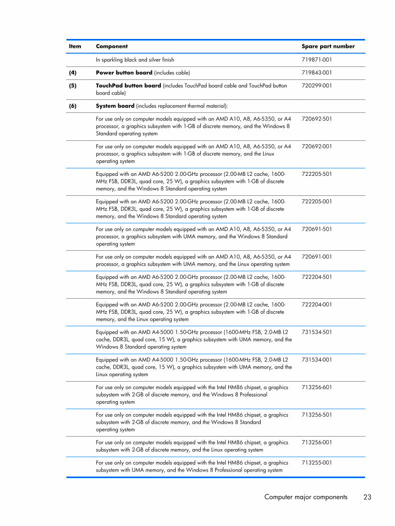
In sparkling black and silver finish 719871-001
(4) Power button board (includes cable) 719843-001
(5) TouchPad button board (includes TouchPad board cable and TouchPad buttonboard cable)
720299-001
(6) System board (includes replacement thermal material):
For use only on computer models equipped with an AMD A10, A8, A6-5350, or A4processor, a graphics subsystem with 1-GB of discrete memory, and the Windows 8Standard operating system
720692-501
For use only on computer models equipped with an AMD A10, A8, A6-5350, or A4processor, a graphics subsystem with 1-GB of discrete memory, and the Linuxoperating system
720692-001
Equipped with an AMD A6-5200 2.00-GHz processor (2.00-MB L2 cache, 1600-MHz FSB, DDR3L, quad core, 25 W), a graphics subsystem with 1-GB of discretememory, and the Windows 8 Standard operating system
722205-501
Equipped with an AMD A6-5200 2.00-GHz processor (2.00-MB L2 cache, 1600-MHz FSB, DDR3L, quad core, 25 W), a graphics subsystem with 1-GB of discretememory, and the Windows 8 Standard operating system
722205-001
For use only on computer models equipped with an AMD A10, A8, A6-5350, or A4processor, a graphics subsystem with UMA memory, and the Windows 8 Standardoperating system
720691-501
For use only on computer models equipped with an AMD A10, A8, A6-5350, or A4processor, a graphics subsystem with UMA memory, and the Linux operating system
720691-001
Equipped with an AMD A6-5200 2.00-GHz processor (2.00-MB L2 cache, 1600-MHz FSB, DDR3L, quad core, 25 W), a graphics subsystem with 1-GB of discretememory, and the Windows 8 Standard operating system
722204-501
Equipped with an AMD A6-5200 2.00-GHz processor (2.00-MB L2 cache, 1600-MHz FSB, DDR3L, quad core, 25 W), a graphics subsystem with 1-GB of discretememory, and the Linux operating system
722204-001
Equipped with an AMD A4-5000 1.50-GHz processor (1600-MHz FSB, 2.0-MB L2cache, DDR3L, quad core, 15 W), a graphics subsystem with UMA memory, and theWindows 8 Standard operating system
731534-501
Equipped with an AMD A4-5000 1.50-GHz processor (1600-MHz FSB, 2.0-MB L2cache, DDR3L, quad core, 15 W), a graphics subsystem with UMA memory, and theLinux operating system
731534-001
For use only on computer models equipped with the Intel HM86 chipset, a graphicssubsystem with 2-GB of discrete memory, and the Windows 8 Professionaloperating system
713256-601
For use only on computer models equipped with the Intel HM86 chipset, a graphicssubsystem with 2-GB of discrete memory, and the Windows 8 Standardoperating system
713256-501
For use only on computer models equipped with the Intel HM86 chipset, a graphicssubsystem with 2-GB of discrete memory, and the Linux operating system
713256-001
For use only on computer models equipped with the Intel HM86 chipset, a graphicssubsystem with UMA memory, and the Windows 8 Professional operating system
713255-001
Computer major components 23
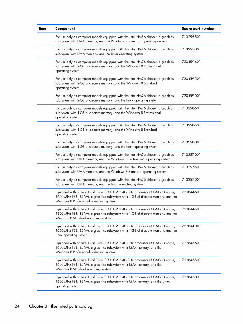
Item Component Spare part number
For use only on computer models equipped with the Intel HM86 chipset, a graphicssubsystem with UMA memory, and the Windows 8 Standard operating system
713255-501
For use only on computer models equipped with the Intel HM86 chipset, a graphicssubsystem with UMA memory, and the Linux operating system
713255-001
For use only on computer models equipped with the Intel HM76 chipset, a graphicssubsystem with 2-GB of discrete memory, and the Windows 8 Professionaloperating system
720459-601
For use only on computer models equipped with the Intel HM76 chipset, a graphicssubsystem with 2-GB of discrete memory, and the Windows 8 Standardoperating system
720459-501
For use only on computer models equipped with the Intel HM76 chipset, a graphicssubsystem with 2-GB of discrete memory, and the Linux operating system
720459-001
For use only on computer models equipped with the Intel HM76 chipset, a graphicssubsystem with 1-GB of discrete memory, and the Windows 8 Professionaloperating system
713258-601
For use only on computer models equipped with the Intel HM76 chipset, a graphicssubsystem with 1-GB of discrete memory, and the Windows 8 Standardoperating system
713258-501
For use only on computer models equipped with the Intel HM76 chipset, a graphicssubsystem with 1-GB of discrete memory, and the Linux operating system
713258-001
For use only on computer models equipped with the Intel HM76 chipset, a graphicssubsystem with UMA memory, and the Windows 8 Professional operating system
713257-001
For use only on computer models equipped with the Intel HM76 chipset, a graphicssubsystem with UMA memory, and the Windows 8 Standard operating system
713257-501
For use only on computer models equipped with the Intel HM76 chipset, a graphicssubsystem with UMA memory, and the Linux operating system
713257-001
Equipped with an Intel Dual Core i3-3110M 2.40-GHz processor (3.0-MB L3 cache,1600-MHz FSB, 35 W), a graphics subsystem with 1-GB of discrete memory, and theWindows 8 Professional operating system
729844-601
Equipped with an Intel Dual Core i3-3110M 2.40-GHz processor (3.0-MB L3 cache,1600-MHz FSB, 35 W), a graphics subsystem with 1-GB of discrete memory, and theWindows 8 Standard operating system
729844-501
Equipped with an Intel Dual Core i3-3110M 2.40-GHz processor (3.0-MB L3 cache,1600-MHz FSB, 35 W), a graphics subsystem with 1-GB of discrete memory, and theLinux operating system
729844-001
Equipped with an Intel Dual Core i3-3110M 2.40-GHz processor (3.0-MB L3 cache,1600-MHz FSB, 35 W), a graphics subsystem with UMA memory, and theWindows 8 Professional operating system
729843-601
Equipped with an Intel Dual Core i3-3110M 2.40-GHz processor (3.0-MB L3 cache,1600-MHz FSB, 35 W), a graphics subsystem with UMA memory, and theWindows 8 Standard operating system
729843-501
Equipped with an Intel Dual Core i3-3110M 2.40-GHz processor (3.0-MB L3 cache,1600-MHz FSB, 35 W), a graphics subsystem with UMA memory, and the Linuxoperating system
729843-001
24 Chapter 3 Illustrated parts catalog
Item Component Spare part number
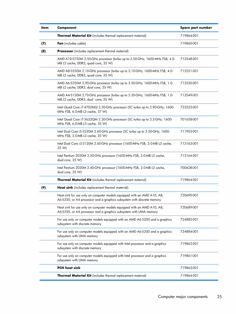
Thermal Material Kit (includes thermal replacement material) 719864-001
(7) Fan (includes cable) 719860-001
(8) Processor (includes replacement thermal material):
AMD A10-5750M 2.50-GHz processor (turbo up to 3.50-GHz; 1600-MHz FSB, 4.0-MB L2 cache, DDR3, quad core, 35 W)
713548-001
AMD A8-5550M 2.10-GHz processor (turbo up to 3.10-GHz; 1600-MHz FSB, 4.0-MB L2 cache, DDR3, quad core, 35 W)
713551-001
AMD A6-5350M 2.90-GHz processor (turbo up to 3.50-GHz; 1600-MHz FSB, 1.0-MB L2 cache, DDR3, dual core, 35 W)
713550-001
AMD A4-5150M 2.70-GHz processor (turbo up to 3.30-GHz; 1600-MHz FSB, 1.0-MB L2 cache, DDR3, dual core, 35 W)
713549-001
Intel Quad Core i7-4702MQ 2.20-GHz processor (SC turbo up to 2.90-GHz; 1600-MHz FSB, 6.0-MB L3 cache, 37 W)
723522-001
Intel Quad Core i7-3632QM 2.20-GHz processor (SC turbo up to 3.2-GHz; 1600-MHz FSB, 6.0-MB L3 cache, 35 W)
701658-001
Intel Dual Core i5-3230M 2.60-GHz processor (SC turbo up to 3.20-GHz; 1600-MHz FSB, 3.0-MB L3 cache, 35 W)
711903-001
Intel Dual Core i3-3130M 2.60-GHz processor (1600-MHz FSB, 3.0-MB L3 cache,35 W)
713163-001
Intel Pentium 2030M 2.50-GHz processor (1600-MHz FSB, 2.0-MB L2 cache,dual core, 35 W)
713164-001
Intel Pentium 2020M 2.40-GHz processor (1600-MHz FSB, 2.0-MB L2 cache,dual core, 35 W)
700628-001
Thermal Material Kit (includes thermal replacement material) 719864-001
(9) Heat sink (includes replacement thermal material):
Heat sink for use only on computer models equipped with an AMD A10, A8,A6-5350, or A4 processor and a graphics subsystem with discrete memory
720690-001
Heat sink for use only on computer models equipped with an AMD A10, A8,A6-5350, or A4 processor and a graphics subsystem with UMA memory
720689-001
For use only on computer models equipped with an AMD A6-5200 and a graphicssubsystem with discrete memory
724885-001
For use only on computer models equipped with an AMD A6-5200 and a graphicssubsystem with UMA memory
724884-001
For use only on computer models equipped with Intel processor and a graphicssubsystem with discrete memory
719862-001
For use only on computer models equipped with Intel processor and a graphicssubsystem with UMA memory
719861-001
PCH heat sink 719863-001
Thermal Material Kit (includes thermal replacement material) 719864-001
Computer major components 25
Item Component Spare part number
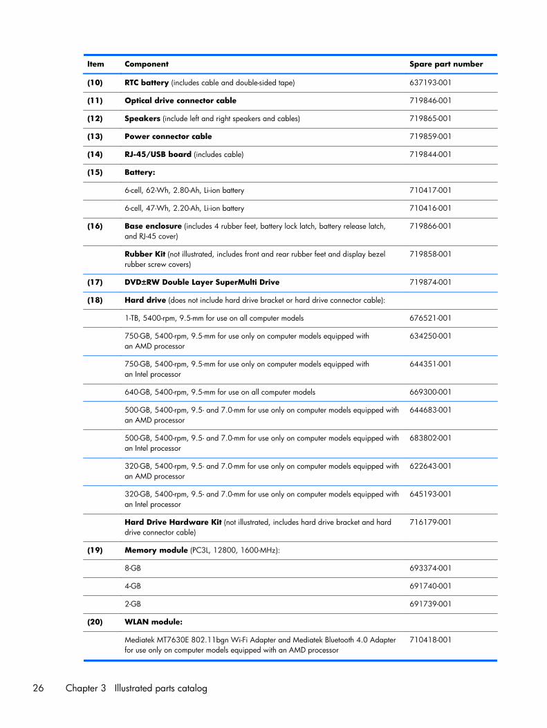
(10) RTC battery (includes cable and double-sided tape) 637193-001
(11) Optical drive connector cable 719846-001
(12) Speakers (include left and right speakers and cables) 719865-001
(13) Power connector cable 719859-001
(14) RJ-45/USB board (includes cable) 719844-001
(15) Battery:
6-cell, 62-Wh, 2.80-Ah, Li-ion battery 710417-001
6-cell, 47-Wh, 2.20-Ah, Li-ion battery 710416-001
(16) Base enclosure (includes 4 rubber feet, battery lock latch, battery release latch,and RJ-45 cover)
719866-001
Rubber Kit (not illustrated, includes front and rear rubber feet and display bezelrubber screw covers)
719858-001
(17) DVD±RW Double Layer SuperMulti Drive 719874-001
(18) Hard drive (does not include hard drive bracket or hard drive connector cable):
1-TB, 5400-rpm, 9.5-mm for use on all computer models 676521-001
750-GB, 5400-rpm, 9.5-mm for use only on computer models equipped withan AMD processor
634250-001
750-GB, 5400-rpm, 9.5-mm for use only on computer models equipped withan Intel processor
644351-001
640-GB, 5400-rpm, 9.5-mm for use on all computer models 669300-001
500-GB, 5400-rpm, 9.5- and 7.0-mm for use only on computer models equipped withan AMD processor
644683-001
500-GB, 5400-rpm, 9.5- and 7.0-mm for use only on computer models equipped withan Intel processor
683802-001
320-GB, 5400-rpm, 9.5- and 7.0-mm for use only on computer models equipped withan AMD processor
622643-001
320-GB, 5400-rpm, 9.5- and 7.0-mm for use only on computer models equipped withan Intel processor
645193-001
Hard Drive Hardware Kit (not illustrated, includes hard drive bracket and harddrive connector cable)
716179-001
(19) Memory module (PC3L, 12800, 1600-MHz):
8-GB 693374-001
4-GB 691740-001
2-GB 691739-001
(20) WLAN module:
Mediatek MT7630E 802.11bgn Wi-Fi Adapter and Mediatek Bluetooth 4.0 Adapterfor use only on computer models equipped with an AMD processor
710418-001
26 Chapter 3 Illustrated parts catalog
Item Component Spare part number
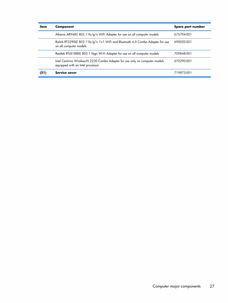
Atheros AR9485 802.11b/g/n WiFi Adapter for use on all computer models 675794-001
Ralink RT3290LE 802.11b/g/n 1×1 WiFi and Bluetooth 4.0 Combo Adapter for useon all computer models
690020-001
Realtek RTL8188EE 802.11bgn Wi-Fi Adapter for use on all computer models 709848-001
Intel Centrino Wireless-N 2230 Combo Adapter for use only on computer modelsequipped with an Intel processor
670290-001
(21) Service cover 719872-001
Computer major components 27
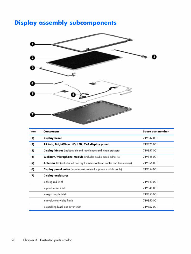
Display assembly subcomponents
Item Component Spare part number
(1) Display bezel 719847-001
(2) 15.6-in, BrightView, HD, LED, SVA display panel 719873-001
(3) Display hinges (includes left and right hinges and hinge brackets) 719857-001
(4) Webcam/microphone module (includes double-sided adhesive) 719845-001
(5) Antenna Kit (includes left and right wireless antenna cables and transceivers) 719856-001
(6) Display panel cable (includes webcam/microphone module cable) 719854-001
(7) Display enclosure:
In flying red finish 719849-001
In pearl white finish 719848-001
In regal purple finish 719851-001
In revolutionary blue finish 719850-001
In sparkling black and silver finish 719852-001
28 Chapter 3 Illustrated parts catalog
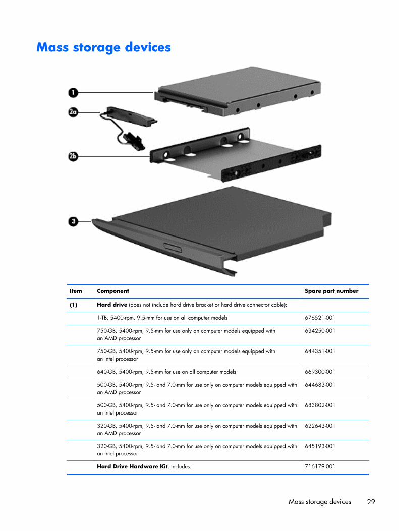
Mass storage devices
Item Component Spare part number
(1) Hard drive (does not include hard drive bracket or hard drive connector cable):
1-TB, 5400-rpm, 9.5-mm for use on all computer models 676521-001
750-GB, 5400-rpm, 9.5-mm for use only on computer models equipped withan AMD processor
634250-001
750-GB, 5400-rpm, 9.5-mm for use only on computer models equipped withan Intel processor
644351-001
640-GB, 5400-rpm, 9.5-mm for use on all computer models 669300-001
500-GB, 5400-rpm, 9.5- and 7.0-mm for use only on computer models equipped withan AMD processor
644683-001
500-GB, 5400-rpm, 9.5- and 7.0-mm for use only on computer models equipped withan Intel processor
683802-001
320-GB, 5400-rpm, 9.5- and 7.0-mm for use only on computer models equipped withan AMD processor
622643-001
320-GB, 5400-rpm, 9.5- and 7.0-mm for use only on computer models equipped withan Intel processor
645193-001
Hard Drive Hardware Kit, includes: 716179-001
Mass storage devices 29
Item Component Spare part number
(2a) Hard drive connector cable
(2b) Hard drive bracket
(3) DVD±RW Double Layer SuperMulti Drive 719874-001
Miscellaneous parts
Component Spare part number
AC adapter:
90-W HP Smart AC adapter (PFC, EM, 4.5-mm) 710414-001
90-W HP Smart AC adapter (PFC, 4.5-mm) 710413-001
65-W HP Smart AC adapter (non-PFC, EM, 4.5-mm) 714657-001
65-W HP Smart AC adapter (non-PFC, 4.5-mm) 710412-001
Power cord (3-pin, black, 1.83-m):
For use on all computer models in Australia 490371-111
For use on all computer models in Denmark 490371-081
For use on all computer models in Europe 490371-021
For use on all computer models in India 490371-D61
For use on all computer models in Israel 490371-BB1
For use on all computer models in Italy 490371-061
For use only on computer models equipped with an Intel processor in Japan 490371-291
For use on all computer models in North America 490371-001
For use on all computer models in the People's Republic of China 490371-AA1
For use only on computer models equipped with an Intel processor in South Africa 490371-AR1
For use on all computer models in South Korea 490371-AD1
For use on all computer models in Switzerland 490371-111
For use on all computer models in Taiwan 490371-AB1
For use only on computer models equipped with an Intel processor in Thailand 490371-201
For use only on all computer models in the United Kingdom and Singapore 490371-031
Screw Kit 719855-001
30 Chapter 3 Illustrated parts catalog
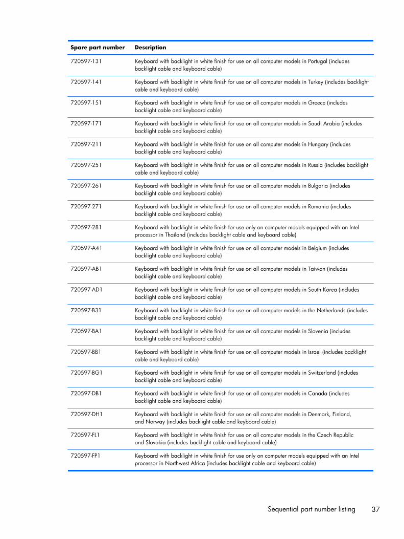
Sequential part number listing
Spare part number Description
490371-001 Power cord for use on all computer models in North America(3-pin, black, 1.83-m)
490371-011 Power cord for use on all computer models in Australia (3-pin, black, 1.83-m)
490371-021 Power cord for use on all computer models in Europe (3-pin, black, 1.83-m)
490371-031 Power cord for use on all computer models in the United Kingdom and Singapore (3-pin, black,1.83-m)
490371-061 Power cord for use on all computer models in Italy (3-pin, black, 1.83-m)
490371-081 Power cord for use on all computer models in Denmark (3-pin, black, 1.83-m)
490371-111 Power cord for use on all computer models in Switzerland (3-pin, black, 1.83-m)
490371-201 Power cord for use only on computer models equipped with an Intel processor in Thailand (3-pin,black, 1.83-m)
490371-291 Power cord for use only on computer models equipped with an Intel processor in Japan (3-pin,black, 1.83-m)
490371-AA1 Power cord for use on all computer models in the People's Republic of China (3-pin, black, 1.83-m)
490371-AB1 Power cord for use on all computer models in Taiwan (3-pin, black, 1.83-m)
490371-AD1 Power cord for use on all computer models in South Korea (3-pin, black, 1.83-m)
490371-AR1 Power cord for use only on computer models equipped with an Intel processor in South Africa (3-pin, black, 1.83-m)
490371-BB1 Power cord for use on all computer models in Israel (3-pin, black, 1.83-m)
490371-D61 Power cord for use on all computer models in India (3-pin, black, 1.83-m)
622643-001 320-GB, 5400-rpm, SATA, 9.5-mm hard drive for use only on computer models equipped with anAMD processor (does not include hard drive bracket or hard drive connector cable)
NOTE: The hard drive bracket and screws are included in the Hard Drive Hardware Kit, sparepart number 716179-001.
634250-001 750-GB, 5400-rpm, SATA, 9.5-mm hard drive for use only on computer models equipped with anAMD processor (does not include hard drive bracket or hard drive connector cable)
NOTE: The hard drive bracket and screws are included in the Hard Drive Hardware Kit, sparepart number 716179-001.
637193-001 RTC battery (includes cable and double-sided tape)
644351-001 750-GB, 5400-rpm, SATA, 7.0-mm hard drive for use only on computer models equipped with anIntel processor (does not include hard drive bracket or hard drive connector cable)
NOTE: The hard drive bracket and screws are included in the Hard Drive Hardware Kit, sparepart number 716179-001.
644683-001 500-GB, 5400-rpm, SATA, 7.0-mm hard drive for use only on computer models equipped with anAMD processor (does not include hard drive bracket or hard drive connector cable)
NOTE: The hard drive bracket and screws are included in the Hard Drive Hardware Kit, sparepart number 716179-001.
Sequential part number listing 31
Spare part number Description
645193-001 320-GB, 5400-rpm, SATA, 7.0-mm hard drive for use only on computer models equipped with anIntel processor (does not include hard drive bracket or hard drive connector cable)
NOTE: The hard drive bracket and screws are included in the Hard Drive Hardware Kit, sparepart number 716179-001.
669300-001 640-GB, 5400-rpm, SATA, 9.5-mm hard drive for use on all computer models (does not includehard drive bracket or hard drive connector cable)
NOTE: The hard drive bracket and screws are included in the Hard Drive Hardware Kit, sparepart number 716179-001.
670290-001 Intel Centrino Wireless-N 2230 Combo Adapter for use only on computer models equipped with anIntel processor
675794-001 Atheros AR9485 802.11b/g/n WiFi Adapter for use on all computer models
676521-001 1-TB, 5400-rpm, SATA, 9.5-mm hard drive (does not include hard drive bracket or hard driveconnector cable)
NOTE: The hard drive bracket and screws are included in the Hard Drive Hardware Kit, sparepart number 716179-001.
683802-001 500-GB, 5400-rpm, SATA, 9.5- and 7.0-mm hard drive for use only on computer models equippedwith an Intel processor (does not include hard drive bracket or hard drive connector cable)
NOTE: The hard drive bracket and screws are included in the Hard Drive Hardware Kit, sparepart number 716179-001.
690020-001 Ralink RT3290LE 802.11b/g/n 1×1 WiFi and Bluetooth 4.0 Combo Adapter for use on allcomputer models
691739-001 2-GB memory module (PC3L, 12800, 1600-MHz)
691740-001 4-GB memory module (PC3L, 12800, 1600-MHz)
693374-001 8-GB memory module (PC3L, 12800, 1600-MHz)
700628-001 Intel Pentium 2020M 2.40-GHz processor (1600-MHz FSB, 2.0-MB L2 cache, dual core, 35 W;includes replacement thermal material)
701658-001 Intel Quad Core i7-3632QM 2.20-GHz processor (SC turbo up to 3.2-GHz; 1600-MHz FSB, 6.0-MB L3 cache, 35 W; includes replacement thermal material)
709848-001 Realtek RTL8188EE 802.11bgn Wi-Fi Adapter for use on all computer models
710412-001 65-W HP Smart AC adapter (non-PFC, 4.5-mm)
710413-001 90-W HP Smart AC adapter (PFC, 4.5-mm)
710414-001 90-W HP Smart AC adapter (PFC, EM, 4.5-mm)
710416-001 6-cell, 47-Wh, 2.20-Ah, Li-ion battery
710417-001 6-cell, 62-Wh, 2.80-Ah, Li-ion battery
710418-001 Mediatek MT7630E 802.11bgn Wi-Fi Adapter and Mediatek Bluetooth 4.0 Adapter for use onlyon computer models equipped with an AMD processor
711903-001 Intel Dual Core i5-3230M 2.60-GHz processor (SC turbo up to 3.20-GHz; 1600-MHz FSB, 3.0-MBL3 cache, 35 W; includes replacement thermal material)
32 Chapter 3 Illustrated parts catalog
Spare part number Description
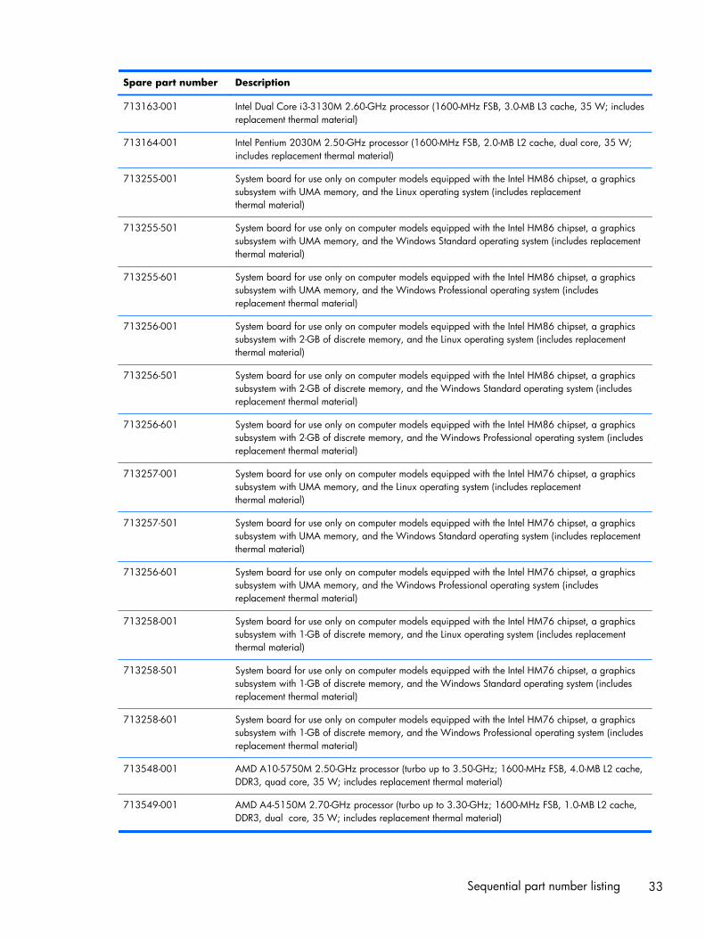
713163-001 Intel Dual Core i3-3130M 2.60-GHz processor (1600-MHz FSB, 3.0-MB L3 cache, 35 W; includesreplacement thermal material)
713164-001 Intel Pentium 2030M 2.50-GHz processor (1600-MHz FSB, 2.0-MB L2 cache, dual core, 35 W;includes replacement thermal material)
713255-001 System board for use only on computer models equipped with the Intel HM86 chipset, a graphicssubsystem with UMA memory, and the Linux operating system (includes replacementthermal material)
713255-501 System board for use only on computer models equipped with the Intel HM86 chipset, a graphicssubsystem with UMA memory, and the Windows Standard operating system (includes replacementthermal material)
713255-601 System board for use only on computer models equipped with the Intel HM86 chipset, a graphicssubsystem with UMA memory, and the Windows Professional operating system (includesreplacement thermal material)
713256-001 System board for use only on computer models equipped with the Intel HM86 chipset, a graphicssubsystem with 2-GB of discrete memory, and the Linux operating system (includes replacementthermal material)
713256-501 System board for use only on computer models equipped with the Intel HM86 chipset, a graphicssubsystem with 2-GB of discrete memory, and the Windows Standard operating system (includesreplacement thermal material)
713256-601 System board for use only on computer models equipped with the Intel HM86 chipset, a graphicssubsystem with 2-GB of discrete memory, and the Windows Professional operating system (includesreplacement thermal material)
713257-001 System board for use only on computer models equipped with the Intel HM76 chipset, a graphicssubsystem with UMA memory, and the Linux operating system (includes replacementthermal material)
713257-501 System board for use only on computer models equipped with the Intel HM76 chipset, a graphicssubsystem with UMA memory, and the Windows Standard operating system (includes replacementthermal material)
713256-601 System board for use only on computer models equipped with the Intel HM76 chipset, a graphicssubsystem with UMA memory, and the Windows Professional operating system (includesreplacement thermal material)
713258-001 System board for use only on computer models equipped with the Intel HM76 chipset, a graphicssubsystem with 1-GB of discrete memory, and the Linux operating system (includes replacementthermal material)
713258-501 System board for use only on computer models equipped with the Intel HM76 chipset, a graphicssubsystem with 1-GB of discrete memory, and the Windows Standard operating system (includesreplacement thermal material)
713258-601 System board for use only on computer models equipped with the Intel HM76 chipset, a graphicssubsystem with 1-GB of discrete memory, and the Windows Professional operating system (includesreplacement thermal material)
713548-001 AMD A10-5750M 2.50-GHz processor (turbo up to 3.50-GHz; 1600-MHz FSB, 4.0-MB L2 cache,DDR3, quad core, 35 W; includes replacement thermal material)
713549-001 AMD A4-5150M 2.70-GHz processor (turbo up to 3.30-GHz; 1600-MHz FSB, 1.0-MB L2 cache,DDR3, dual core, 35 W; includes replacement thermal material)
Sequential part number listing 33
Spare part number Description
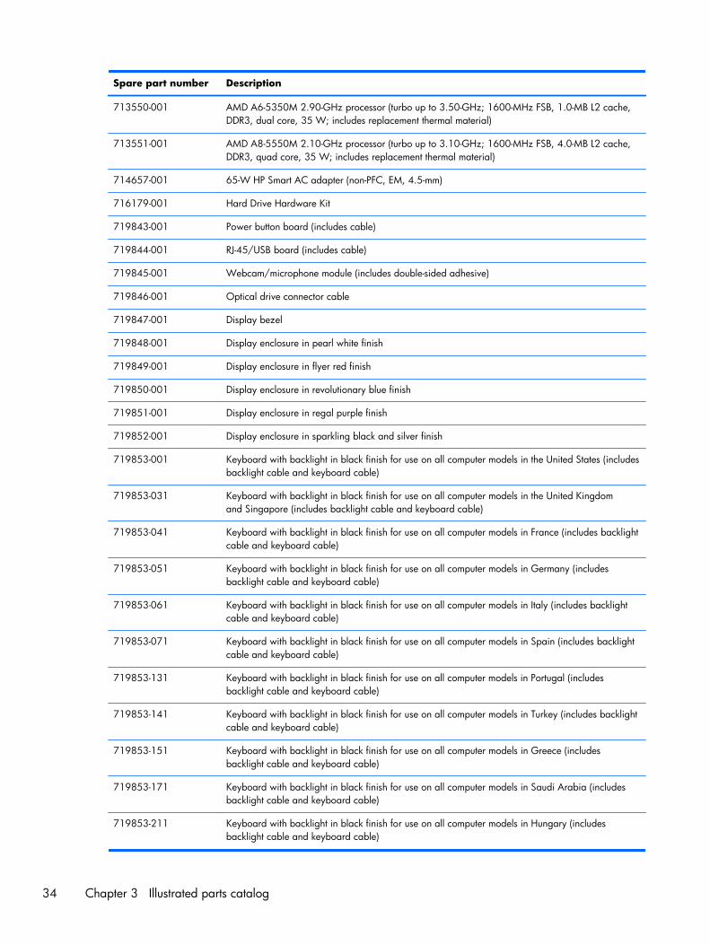
713550-001 AMD A6-5350M 2.90-GHz processor (turbo up to 3.50-GHz; 1600-MHz FSB, 1.0-MB L2 cache,DDR3, dual core, 35 W; includes replacement thermal material)
713551-001 AMD A8-5550M 2.10-GHz processor (turbo up to 3.10-GHz; 1600-MHz FSB, 4.0-MB L2 cache,DDR3, quad core, 35 W; includes replacement thermal material)
714657-001 65-W HP Smart AC adapter (non-PFC, EM, 4.5-mm)
716179-001 Hard Drive Hardware Kit
719843-001 Power button board (includes cable)
719844-001 RJ-45/USB board (includes cable)
719845-001 Webcam/microphone module (includes double-sided adhesive)
719846-001 Optical drive connector cable
719847-001 Display bezel
719848-001 Display enclosure in pearl white finish
719849-001 Display enclosure in flyer red finish
719850-001 Display enclosure in revolutionary blue finish
719851-001 Display enclosure in regal purple finish
719852-001 Display enclosure in sparkling black and silver finish
719853-001 Keyboard with backlight in black finish for use on all computer models in the United States (includesbacklight cable and keyboard cable)
719853-031 Keyboard with backlight in black finish for use on all computer models in the United Kingdomand Singapore (includes backlight cable and keyboard cable)
719853-041 Keyboard with backlight in black finish for use on all computer models in France (includes backlightcable and keyboard cable)
719853-051 Keyboard with backlight in black finish for use on all computer models in Germany (includesbacklight cable and keyboard cable)
719853-061 Keyboard with backlight in black finish for use on all computer models in Italy (includes backlightcable and keyboard cable)
719853-071 Keyboard with backlight in black finish for use on all computer models in Spain (includes backlightcable and keyboard cable)
719853-131 Keyboard with backlight in black finish for use on all computer models in Portugal (includesbacklight cable and keyboard cable)
719853-141 Keyboard with backlight in black finish for use on all computer models in Turkey (includes backlightcable and keyboard cable)
719853-151 Keyboard with backlight in black finish for use on all computer models in Greece (includesbacklight cable and keyboard cable)
719853-171 Keyboard with backlight in black finish for use on all computer models in Saudi Arabia (includesbacklight cable and keyboard cable)
719853-211 Keyboard with backlight in black finish for use on all computer models in Hungary (includesbacklight cable and keyboard cable)
34 Chapter 3 Illustrated parts catalog
Spare part number Description
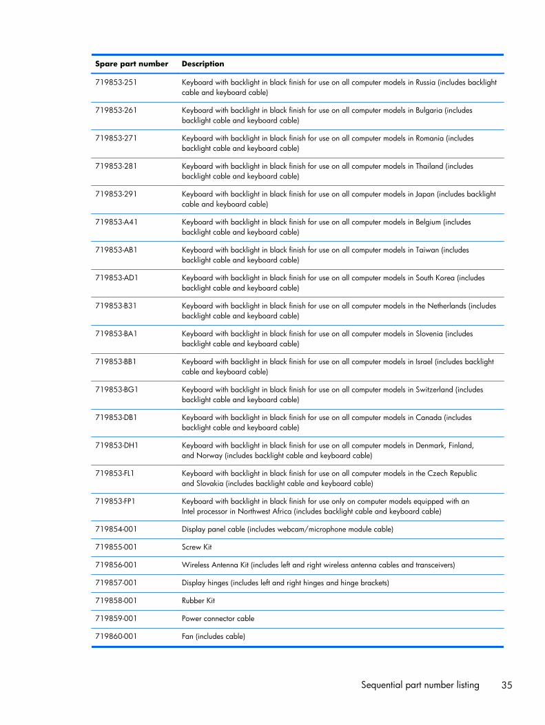
719853-251 Keyboard with backlight in black finish for use on all computer models in Russia (includes backlightcable and keyboard cable)
719853-261 Keyboard with backlight in black finish for use on all computer models in Bulgaria (includesbacklight cable and keyboard cable)
719853-271 Keyboard with backlight in black finish for use on all computer models in Romania (includesbacklight cable and keyboard cable)
719853-281 Keyboard with backlight in black finish for use on all computer models in Thailand (includesbacklight cable and keyboard cable)
719853-291 Keyboard with backlight in black finish for use on all computer models in Japan (includes backlightcable and keyboard cable)
719853-A41 Keyboard with backlight in black finish for use on all computer models in Belgium (includesbacklight cable and keyboard cable)
719853-AB1 Keyboard with backlight in black finish for use on all computer models in Taiwan (includesbacklight cable and keyboard cable)
719853-AD1 Keyboard with backlight in black finish for use on all computer models in South Korea (includesbacklight cable and keyboard cable)
719853-B31 Keyboard with backlight in black finish for use on all computer models in the Netherlands (includesbacklight cable and keyboard cable)
719853-BA1 Keyboard with backlight in black finish for use on all computer models in Slovenia (includesbacklight cable and keyboard cable)
719853-BB1 Keyboard with backlight in black finish for use on all computer models in Israel (includes backlightcable and keyboard cable)
719853-BG1 Keyboard with backlight in black finish for use on all computer models in Switzerland (includesbacklight cable and keyboard cable)
719853-DB1 Keyboard with backlight in black finish for use on all computer models in Canada (includesbacklight cable and keyboard cable)
719853-DH1 Keyboard with backlight in black finish for use on all computer models in Denmark, Finland,and Norway (includes backlight cable and keyboard cable)
719853-FL1 Keyboard with backlight in black finish for use on all computer models in the Czech Republicand Slovakia (includes backlight cable and keyboard cable)
719853-FP1 Keyboard with backlight in black finish for use only on computer models equipped with anIntel processor in Northwest Africa (includes backlight cable and keyboard cable)
719854-001 Display panel cable (includes webcam/microphone module cable)
719855-001 Screw Kit
719856-001 Wireless Antenna Kit (includes left and right wireless antenna cables and transceivers)
719857-001 Display hinges (includes left and right hinges and hinge brackets)
719858-001 Rubber Kit
719859-001 Power connector cable
719860-001 Fan (includes cable)
Sequential part number listing 35
Spare part number Description
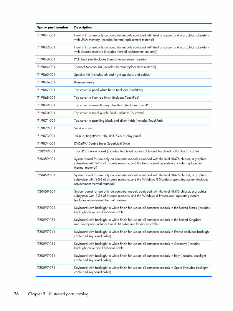
719861-001 Heat sink for use only on computer models equipped with Intel processor and a graphics subsystemwith UMA memory (includes thermal replacement material)
719862-001 Heat sink for use only on computer models equipped with Intel processor and a graphics subsystemwith discrete memory (includes thermal replacement material)
719863-001 PCH heat sink (includes thermal replacement material)
719864-001 Thermal Material Kit (includes thermal replacement material)
719865-001 Speaker Kit (includes left and right speakers and cables)
719866-001 Base enclosure
719867-001 Top cover in pearl white finish (includes TouchPad)
719868-001 Top cover in flyer red finish (includes TouchPad)
719869-001 Top cover in revolutionary blue finish (includes TouchPad)
719870-001 Top cover in regal purple finish (includes TouchPad)
719871-001 Top cover in sparkling black and silver finish (includes TouchPad)
719872-001 Service cover
719873-001 15.6-in, BrightView, HD, LED, SVA display panel
719874-001 DVD±RW Double Layer SuperMulti Drive
720299-001 TouchPad button board (includes TouchPad board cable and TouchPad button board cable)
720459-001 System board for use only on computer models equipped with the Intel HM76 chipset, a graphicssubsystem with 2-GB of discrete memory, and the Linux operating system (includes replacementthermal material)
720459-501 System board for use only on computer models equipped with the Intel HM76 chipset, a graphicssubsystem with 2-GB of discrete memory, and the Windows 8 Standard operating system (includesreplacement thermal material)
720459-601 System board for use only on computer models equipped with the Intel HM76 chipset, a graphicssubsystem with 2-GB of discrete memory, and the Windows 8 Professional operating system(includes replacement thermal material)
720597-001 Keyboard with backlight in white finish for use on all computer models in the United States (includesbacklight cable and keyboard cable)
720597-031 Keyboard with backlight in white finish for use on all computer models in the United Kingdomand Singapore (includes backlight cable and keyboard cable)
720597-041 Keyboard with backlight in white finish for use on all computer models in France (includes backlightcable and keyboard cable)
720597-051 Keyboard with backlight in white finish for use on all computer models in Germany (includesbacklight cable and keyboard cable)
720597-061 Keyboard with backlight in white finish for use on all computer models in Italy (includes backlightcable and keyboard cable)
720597-071 Keyboard with backlight in white finish for use on all computer models in Spain (includes backlightcable and keyboard cable)
36 Chapter 3 Illustrated parts catalog
Spare part number Description
720597-131 Keyboard with backlight in white finish for use on all computer models in Portugal (includesbacklight cable and keyboard cable)
720597-141 Keyboard with backlight in white finish for use on all computer models in Turkey (includes backlightcable and keyboard cable)
720597-151 Keyboard with backlight in white finish for use on all computer models in Greece (includesbacklight cable and keyboard cable)
720597-171 Keyboard with backlight in white finish for use on all computer models in Saudi Arabia (includesbacklight cable and keyboard cable)
720597-211 Keyboard with backlight in white finish for use on all computer models in Hungary (includesbacklight cable and keyboard cable)
720597-251 Keyboard with backlight in white finish for use on all computer models in Russia (includes backlightcable and keyboard cable)
720597-261 Keyboard with backlight in white finish for use on all computer models in Bulgaria (includesbacklight cable and keyboard cable)
720597-271 Keyboard with backlight in white finish for use on all computer models in Romania (includesbacklight cable and keyboard cable)
720597-281 Keyboard with backlight in white finish for use only on computer models equipped with an Intelprocessor in Thailand (includes backlight cable and keyboard cable)
720597-A41 Keyboard with backlight in white finish for use on all computer models in Belgium (includesbacklight cable and keyboard cable)
720597-AB1 Keyboard with backlight in white finish for use on all computer models in Taiwan (includesbacklight cable and keyboard cable)
720597-AD1 Keyboard with backlight in white finish for use on all computer models in South Korea (includesbacklight cable and keyboard cable)
720597-B31 Keyboard with backlight in white finish for use on all computer models in the Netherlands (includesbacklight cable and keyboard cable)
720597-BA1 Keyboard with backlight in white finish for use on all computer models in Slovenia (includesbacklight cable and keyboard cable)
720597-BB1 Keyboard with backlight in white finish for use on all computer models in Israel (includes backlightcable and keyboard cable)
720597-BG1 Keyboard with backlight in white finish for use on all computer models in Switzerland (includesbacklight cable and keyboard cable)
720597-DB1 Keyboard with backlight in white finish for use on all computer models in Canada (includesbacklight cable and keyboard cable)
720597-DH1 Keyboard with backlight in white finish for use on all computer models in Denmark, Finland,and Norway (includes backlight cable and keyboard cable)
720597-FL1 Keyboard with backlight in white finish for use on all computer models in the Czech Republicand Slovakia (includes backlight cable and keyboard cable)
720597-FP1 Keyboard with backlight in white finish for use only on computer models equipped with an Intelprocessor in Northwest Africa (includes backlight cable and keyboard cable)
Sequential part number listing 37
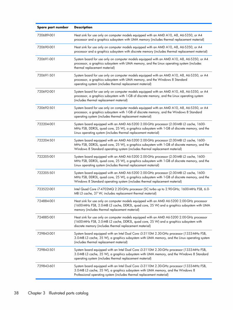
Spare part number Description
720689-001 Heat sink for use only on computer models equipped with an AMD A10, A8, A6-5350, or A4processor and a graphics subsystem with UMA memory (includes thermal replacement material)
720690-001 Heat sink for use only on computer models equipped with an AMD A10, A8, A6-5350, or A4processor and a graphics subsystem with discrete memory (includes thermal replacement material)
720691-001 System board for use only on computer models equipped with an AMD A10, A8, A6-5350, or A4processor, a graphics subsystem with UMA memory, and the Linux operating system (includesthermal replacement material)
720691-501 System board for use only on computer models equipped with an AMD A10, A8, A6-5350, or A4processor, a graphics subsystem with UMA memory, and the Windows 8 Standardoperating system (includes thermal replacement material)
720692-001 System board for use only on computer models equipped with an AMD A10, A8, A6-5350, or A4processor, a graphics subsystem with 1-GB of discrete memory, and the Linux operating system(includes thermal replacement material)
720692-501 System board for use only on computer models equipped with an AMD A10, A8, A6-5350, or A4processor, a graphics subsystem with 1-GB of discrete memory, and the Windows 8 Standardoperating system (includes thermal replacement material)
722204-001 System board equipped with an AMD A6-5200 2.00-GHz processor (2.00-MB L2 cache, 1600-MHz FSB, DDR3L, quad core, 25 W), a graphics subsystem with 1-GB of discrete memory, and theLinux operating system (includes thermal replacement material)
722204-501 System board equipped with an AMD A6-5200 2.00-GHz processor (2.00-MB L2 cache, 1600-MHz FSB, DDR3L, quad core, 25 W), a graphics subsystem with 1-GB of discrete memory, and theWindows 8 Standard operating system (includes thermal replacement material)
722205-001 System board equipped with an AMD A6-5200 2.00-GHz processor (2.00-MB L2 cache, 1600-MHz FSB, DDR3L, quad core, 25 W), a graphics subsystem with 1-GB of discrete memory, and theLinux operating system (includes thermal replacement material)
722205-501 System board equipped with an AMD A6-5200 2.00-GHz processor (2.00-MB L2 cache, 1600-MHz FSB, DDR3L, quad core, 25 W), a graphics subsystem with 1-GB of discrete memory, and theWindows 8 Standard operating system (includes thermal replacement material)
723522-001 Intel Quad Core i7-4702MQ 2.20-GHz processor (SC turbo up to 2.90-GHz; 1600-MHz FSB, 6.0-MB L3 cache, 37 W; includes replacement thermal material)
724884-001 Heat sink for use only on computer models equipped with an AMD A6-5200 2.00-GHz processor(1600-MHz FSB, 2.0-MB L2 cache, DDR3L, quad core, 25 W) and a graphics subsystem with UMAmemory (includes thermal replacement material)
724885-001 Heat sink for use only on computer models equipped with an AMD A6-5200 2.00-GHz processor(1600-MHz FSB, 2.0-MB L2 cache, DDR3L, quad core, 25 W) and a graphics subsystem withdiscrete memory (includes thermal replacement material)
729843-001 System board equipped with an Intel Dual Core i3-3110M 2.30-GHz processor (1333-MHz FSB,3.0-MB L3 cache, 35 W), a graphics subsystem with UMA memory, and the Linux operating system(includes thermal replacement material)
729843-501 System board equipped with an Intel Dual Core i3-3110M 2.30-GHz processor (1333-MHz FSB,3.0-MB L3 cache, 35 W), a graphics subsystem with UMA memory, and the Windows 8 Standardoperating system (includes thermal replacement material)
729843-601 System board equipped with an Intel Dual Core i3-3110M 2.30-GHz processor (1333-MHz FSB,3.0-MB L3 cache, 35 W), a graphics subsystem with UMA memory, and the Windows 8Professional operating system (includes thermal replacement material)
38 Chapter 3 Illustrated parts catalog
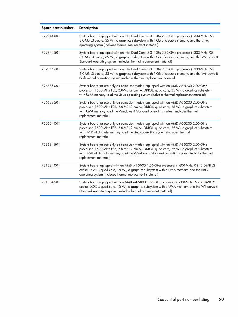
Spare part number Description
729844-001 System board equipped with an Intel Dual Core i3-3110M 2.30-GHz processor (1333-MHz FSB,3.0-MB L3 cache, 35 W), a graphics subsystem with 1-GB of discrete memory, and the Linuxoperating system (includes thermal replacement material)
729844-501 System board equipped with an Intel Dual Core i3-3110M 2.30-GHz processor (1333-MHz FSB,3.0-MB L3 cache, 35 W), a graphics subsystem with 1-GB of discrete memory, and the Windows 8Standard operating system (includes thermal replacement material)
729844-601 System board equipped with an Intel Dual Core i3-3110M 2.30-GHz processor (1333-MHz FSB,3.0-MB L3 cache, 35 W), a graphics subsystem with 1-GB of discrete memory, and the Windows 8Professional operating system (includes thermal replacement material)
726633-001 System board for use only on computer models equipped with an AMD A6-5200 2.00-GHzprocessor (1600-MHz FSB, 2.0-MB L2 cache, DDR3L, quad core, 25 W), a graphics subsystemwith UMA memory, and the Linux operating system (includes thermal replacement material)
726633-501 System board for use only on computer models equipped with an AMD A6-5200 2.00-GHzprocessor (1600-MHz FSB, 2.0-MB L2 cache, DDR3L, quad core, 25 W), a graphics subsystemwith UMA memory, and the Windows 8 Standard operating system (includes thermalreplacement material)
726634-001 System board for use only on computer models equipped with an AMD A6-5200 2.00-GHzprocessor (1600-MHz FSB, 2.0-MB L2 cache, DDR3L, quad core, 25 W), a graphics subsystemwith 1-GB of discrete memory, and the Linux operating system (includes thermalreplacement material)
726634-501 System board for use only on computer models equipped with an AMD A6-5200 2.00-GHzprocessor (1600-MHz FSB, 2.0-MB L2 cache, DDR3L, quad core, 25 W), a graphics subsystemwith 1-GB of discrete memory, and the Windows 8 Standard operating system (includes thermalreplacement material)
731534-001 System board equipped with an AMD A4-5000 1.50-GHz processor (1600-MHz FSB, 2.0-MB L2cache, DDR3L, quad core, 15 W), a graphics subsystem with a UMA memory, and the Linuxoperating system (includes thermal replacement material)
731534-501 System board equipped with an AMD A4-5000 1.50-GHz processor (1600-MHz FSB, 2.0-MB L2cache, DDR3L, quad core, 15 W), a graphics subsystem with a UMA memory, and the Windows 8Standard operating system (includes thermal replacement material)
Sequential part number listing 39
4 Removal and replacementprocedures preliminaryrequirements
Tools requiredYou will need the following tools to complete the removal and replacement procedures:
● Flat-bladed screw driver
● Magnetic screw driver
● Phillips P0 and P1 screw drivers
Service considerationsThe following sections include some of the considerations that you must keep in mind duringdisassembly and assembly procedures.
NOTE: As you remove each subassembly from the computer, place the subassembly (and allaccompanying screws) away from the work area to prevent damage.
Plastic parts
CAUTION: Using excessive force during disassembly and reassembly can damage plastic parts. Usecare when handling the plastic parts. Apply pressure only at the points designated in the maintenanceinstructions.
40 Chapter 4 Removal and replacement procedures preliminary requirements
Cables and connectors
CAUTION: When servicing the computer, be sure that cables are placed in their proper locationsduring the reassembly process. Improper cable placement can damage the computer.
Cables must be handled with extreme care to avoid damage. Apply only the tension required to unseator seat the cables during removal and insertion. Handle cables by the connector whenever possible. Inall cases, avoid bending, twisting, or tearing cables. Be sure that cables are routed in such a way thatthey cannot be caught or snagged by parts being removed or replaced. Handle flex cables withextreme care; these cables tear easily.
Drive handling
CAUTION: Drives are fragile components that must be handled with care. To prevent damage to thecomputer, damage to a drive, or loss of information, observe these precautions:
Before removing or inserting a hard drive, shut down the computer. If you are unsure whether thecomputer is off or in Hibernation, turn the computer on, and then shut it down through the operatingsystem.
Before handling a drive, be sure that you are discharged of static electricity. While handling a drive,avoid touching the connector.
Before removing a diskette drive or optical drive, be sure that a diskette or disc is not in the drive andbe sure that the optical drive tray is closed.
Handle drives on surfaces covered with at least one inch of shock-proof foam.
Avoid dropping drives from any height onto any surface.
After removing a hard drive, an optical drive, or a diskette drive, place it in a static-proof bag.
Avoid exposing an internal hard drive to products that have magnetic fields, such as monitors orspeakers.
Avoid exposing a drive to temperature extremes or liquids.
If a drive must be mailed, place the drive in a bubble pack mailer or other suitable form of protectivepackaging and label the package “FRAGILE.”
Service considerations 41
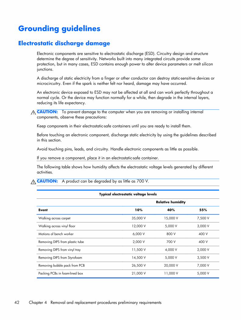
Grounding guidelines
Electrostatic discharge damage
Electronic components are sensitive to electrostatic discharge (ESD). Circuitry design and structuredetermine the degree of sensitivity. Networks built into many integrated circuits provide someprotection, but in many cases, ESD contains enough power to alter device parameters or melt siliconjunctions.
A discharge of static electricity from a finger or other conductor can destroy static-sensitive devices ormicrocircuitry. Even if the spark is neither felt nor heard, damage may have occurred.
An electronic device exposed to ESD may not be affected at all and can work perfectly throughout anormal cycle. Or the device may function normally for a while, then degrade in the internal layers,reducing its life expectancy.
CAUTION: To prevent damage to the computer when you are removing or installing internalcomponents, observe these precautions:
Keep components in their electrostatic-safe containers until you are ready to install them.
Before touching an electronic component, discharge static electricity by using the guidelines describedin this section.
Avoid touching pins, leads, and circuitry. Handle electronic components as little as possible.
If you remove a component, place it in an electrostatic-safe container.
The following table shows how humidity affects the electrostatic voltage levels generated by differentactivities.
CAUTION: A product can be degraded by as little as 700 V.
Typical electrostatic voltage levels
Relative humidity
Event 10% 40% 55%
Walking across carpet 35,000 V 15,000 V 7,500 V
Walking across vinyl floor 12,000 V 5,000 V 3,000 V
Motions of bench worker 6,000 V 800 V 400 V
Removing DIPS from plastic tube 2,000 V 700 V 400 V
Removing DIPS from vinyl tray 11,500 V 4,000 V 2,000 V
Removing DIPS from Styrofoam 14,500 V 5,000 V 3,500 V
Removing bubble pack from PCB 26,500 V 20,000 V 7,000 V
Packing PCBs in foam-lined box 21,000 V 11,000 V 5,000 V
42 Chapter 4 Removal and replacement procedures preliminary requirements
Packaging and transporting guidelines
Follow these grounding guidelines when packaging and transporting equipment:
● To avoid hand contact, transport products in static-safe tubes, bags, or boxes.
● Protect ESD-sensitive parts and assemblies with conductive or approved containers or packaging.
● Keep ESD-sensitive parts in their containers until the parts arrive at static-free workstations.
● Place items on a grounded surface before removing items from their containers.
● Always be properly grounded when touching a component or assembly.
● Store reusable ESD-sensitive parts from assemblies in protective packaging or nonconductivefoam.
● Use transporters and conveyors made of antistatic belts and roller bushings. Be sure thatmechanized equipment used for moving materials is wired to ground and that proper materialsare selected to avoid static charging. When grounding is not possible, use an ionizer to dissipateelectric charges.
Workstation guidelines
Follow these grounding workstation guidelines:
● Cover the workstation with approved static-shielding material.
● Use a wrist strap connected to a properly grounded work surface and use properly grounded toolsand equipment.
● Use conductive field service tools, such as cutters, screw drivers, and vacuums.
● When fixtures must directly contact dissipative surfaces, use fixtures made only of static-safematerials.
● Keep the work area free of nonconductive materials, such as ordinary plastic assembly aids andStyrofoam.
● Handle ESD-sensitive components, parts, and assemblies by the case or PCM laminate. Handlethese items only at static-free workstations.
● Avoid contact with pins, leads, or circuitry.
● Turn off power and input signals before inserting or removing connectors or test equipment.
Grounding guidelines 43
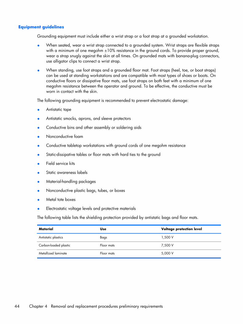
Equipment guidelines
Grounding equipment must include either a wrist strap or a foot strap at a grounded workstation.
● When seated, wear a wrist strap connected to a grounded system. Wrist straps are flexible strapswith a minimum of one megohm ±10% resistance in the ground cords. To provide proper ground,wear a strap snugly against the skin at all times. On grounded mats with banana-plug connectors,use alligator clips to connect a wrist strap.
● When standing, use foot straps and a grounded floor mat. Foot straps (heel, toe, or boot straps)can be used at standing workstations and are compatible with most types of shoes or boots. Onconductive floors or dissipative floor mats, use foot straps on both feet with a minimum of onemegohm resistance between the operator and ground. To be effective, the conductive must beworn in contact with the skin.
The following grounding equipment is recommended to prevent electrostatic damage:
● Antistatic tape
● Antistatic smocks, aprons, and sleeve protectors
● Conductive bins and other assembly or soldering aids
● Nonconductive foam
● Conductive tabletop workstations with ground cords of one megohm resistance
● Static-dissipative tables or floor mats with hard ties to the ground
● Field service kits
● Static awareness labels
● Material-handling packages
● Nonconductive plastic bags, tubes, or boxes
● Metal tote boxes
● Electrostatic voltage levels and protective materials
The following table lists the shielding protection provided by antistatic bags and floor mats.
Material Use Voltage protection level
Antistatic plastics Bags 1,500 V
Carbon-loaded plastic Floor mats 7,500 V
Metallized laminate Floor mats 5,000 V
44 Chapter 4 Removal and replacement procedures preliminary requirements
5 Removal and replacementprocedures for Customer Self-Repair parts
NOTE: The Customer Self-Repair program is not available in all locations. Installing a part notsupported by the Customer Self-Repair program may void your warranty. Check your warranty todetermine if Customer Self-Repair is supported in your location.
Component replacement proceduresNOTE: Please read and follow the procedures described here to access and replace Customer Self-Repair parts successfully.
NOTE: Details about your computer, including model, serial number, product key, and length ofwarranty, are on the service tag at the bottom of your computer. See Service tag on page 16 fordetails.
This chapter provides removal and replacement procedures for Customer Self-Repair parts.
There are as many as 9 screws that must be removed, replaced, and/or loosened when servicingCustomer Self-Repair parts. Make special note of each screw size and location during removal andreplacement.
Component replacement procedures 45
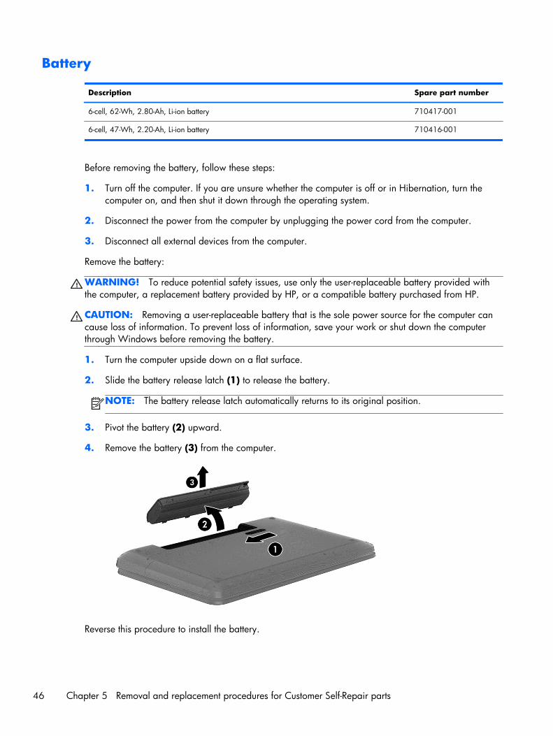
Battery
Description Spare part number
6-cell, 62-Wh, 2.80-Ah, Li-ion battery 710417-001
6-cell, 47-Wh, 2.20-Ah, Li-ion battery 710416-001
Before removing the battery, follow these steps:
1. Turn off the computer. If you are unsure whether the computer is off or in Hibernation, turn thecomputer on, and then shut it down through the operating system.
2. Disconnect the power from the computer by unplugging the power cord from the computer.
3. Disconnect all external devices from the computer.
Remove the battery:
WARNING! To reduce potential safety issues, use only the user-replaceable battery provided withthe computer, a replacement battery provided by HP, or a compatible battery purchased from HP.
CAUTION: Removing a user-replaceable battery that is the sole power source for the computer cancause loss of information. To prevent loss of information, save your work or shut down the computerthrough Windows before removing the battery.
1. Turn the computer upside down on a flat surface.
2. Slide the battery release latch (1) to release the battery.
NOTE: The battery release latch automatically returns to its original position.
3. Pivot the battery (2) upward.
4. Remove the battery (3) from the computer.
Reverse this procedure to install the battery.
46 Chapter 5 Removal and replacement procedures for Customer Self-Repair parts
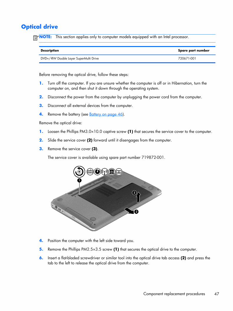
Optical drive
NOTE: This section applies only to computer models equipped with an Intel processor.
Description Spare part number
DVD+/-RW Double Layer SuperMulti Drive 720671-001
Before removing the optical drive, follow these steps:
1. Turn off the computer. If you are unsure whether the computer is off or in Hibernation, turn thecomputer on, and then shut it down through the operating system.
2. Disconnect the power from the computer by unplugging the power cord from the computer.
3. Disconnect all external devices from the computer.
4. Remove the battery (see Battery on page 46).
Remove the optical drive:
1. Loosen the Phillips PM3.0×10.0 captive screw (1) that secures the service cover to the computer.
2. Slide the service cover (2) forward until it disengages from the computer.
3. Remove the service cover (3).
The service cover is available using spare part number 719872-001.
4. Position the computer with the left side toward you.
5. Remove the Phillips PM2.5×3.5 screw (1) that secures the optical drive to the computer.
6. Insert a flat-bladed screwdriver or similar tool into the optical drive tab access (2) and press thetab to the left to release the optical drive from the computer.
Component replacement procedures 47
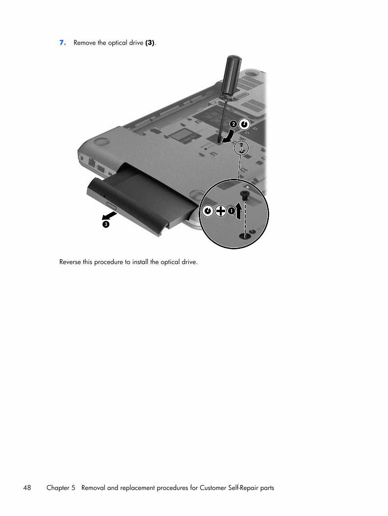
7. Remove the optical drive (3).
Reverse this procedure to install the optical drive.
48 Chapter 5 Removal and replacement procedures for Customer Self-Repair parts
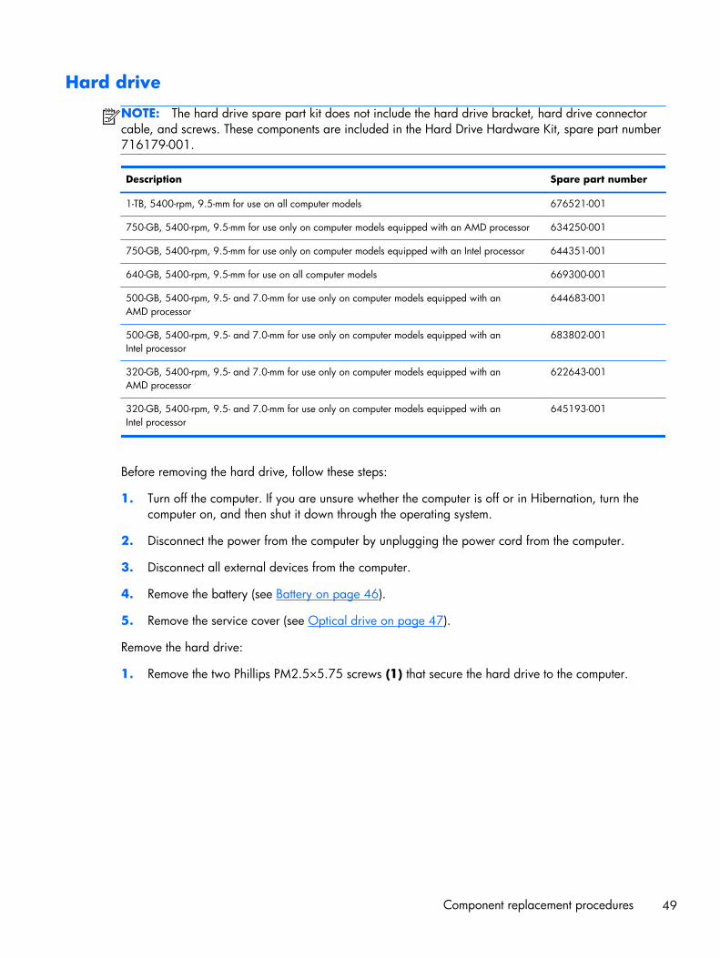
Hard drive
NOTE: The hard drive spare part kit does not include the hard drive bracket, hard drive connectorcable, and screws. These components are included in the Hard Drive Hardware Kit, spare part number716179-001.
Description Spare part number
1-TB, 5400-rpm, 9.5-mm for use on all computer models 676521-001
750-GB, 5400-rpm, 9.5-mm for use only on computer models equipped with an AMD processor 634250-001
750-GB, 5400-rpm, 9.5-mm for use only on computer models equipped with an Intel processor 644351-001
640-GB, 5400-rpm, 9.5-mm for use on all computer models 669300-001
500-GB, 5400-rpm, 9.5- and 7.0-mm for use only on computer models equipped with anAMD processor
644683-001
500-GB, 5400-rpm, 9.5- and 7.0-mm for use only on computer models equipped with anIntel processor
683802-001
320-GB, 5400-rpm, 9.5- and 7.0-mm for use only on computer models equipped with anAMD processor
622643-001
320-GB, 5400-rpm, 9.5- and 7.0-mm for use only on computer models equipped with anIntel processor
645193-001
Before removing the hard drive, follow these steps:
1. Turn off the computer. If you are unsure whether the computer is off or in Hibernation, turn thecomputer on, and then shut it down through the operating system.
2. Disconnect the power from the computer by unplugging the power cord from the computer.
3. Disconnect all external devices from the computer.
4. Remove the battery (see Battery on page 46).
5. Remove the service cover (see Optical drive on page 47).
Remove the hard drive:
1. Remove the two Phillips PM2.5×5.75 screws (1) that secure the hard drive to the computer.
Component replacement procedures 49
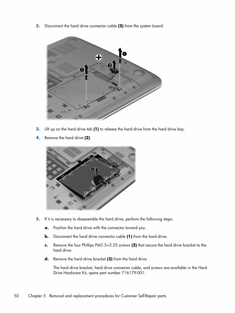
2. Disconnect the hard drive connector cable (2) from the system board.
3. Lift up on the hard drive tab (1) to release the hard drive from the hard drive bay.
4. Remove the hard drive (2).
5. If it is necessary to disassemble the hard drive, perform the following steps:
a. Position the hard drive with the connector toward you.
b. Disconnect the hard drive connector cable (1) from the hard drive.
c. Remove the four Phillips PM2.5×3.25 screws (2) that secure the hard drive bracket to thehard drive.
d. Remove the hard drive bracket (3) from the hard drive.
The hard drive bracket, hard drive connector cable, and screws are available in the HardDrive Hardware Kit, spare part number 716179-001.
50 Chapter 5 Removal and replacement procedures for Customer Self-Repair parts
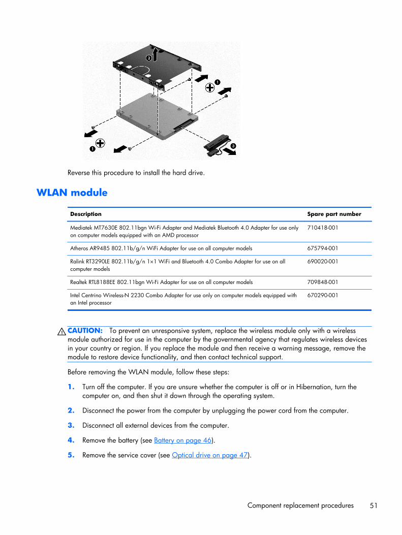
Reverse this procedure to install the hard drive.
WLAN module
Description Spare part number
Mediatek MT7630E 802.11bgn Wi-Fi Adapter and Mediatek Bluetooth 4.0 Adapter for use onlyon computer models equipped with an AMD processor
710418-001
Atheros AR9485 802.11b/g/n WiFi Adapter for use on all computer models 675794-001
Ralink RT3290LE 802.11b/g/n 1×1 WiFi and Bluetooth 4.0 Combo Adapter for use on allcomputer models
690020-001
Realtek RTL8188EE 802.11bgn Wi-Fi Adapter for use on all computer models 709848-001
Intel Centrino Wireless-N 2230 Combo Adapter for use only on computer models equipped withan Intel processor
670290-001
CAUTION: To prevent an unresponsive system, replace the wireless module only with a wirelessmodule authorized for use in the computer by the governmental agency that regulates wireless devicesin your country or region. If you replace the module and then receive a warning message, remove themodule to restore device functionality, and then contact technical support.
Before removing the WLAN module, follow these steps:
1. Turn off the computer. If you are unsure whether the computer is off or in Hibernation, turn thecomputer on, and then shut it down through the operating system.
2. Disconnect the power from the computer by unplugging the power cord from the computer.
3. Disconnect all external devices from the computer.
4. Remove the battery (see Battery on page 46).
5. Remove the service cover (see Optical drive on page 47).
Component replacement procedures 51
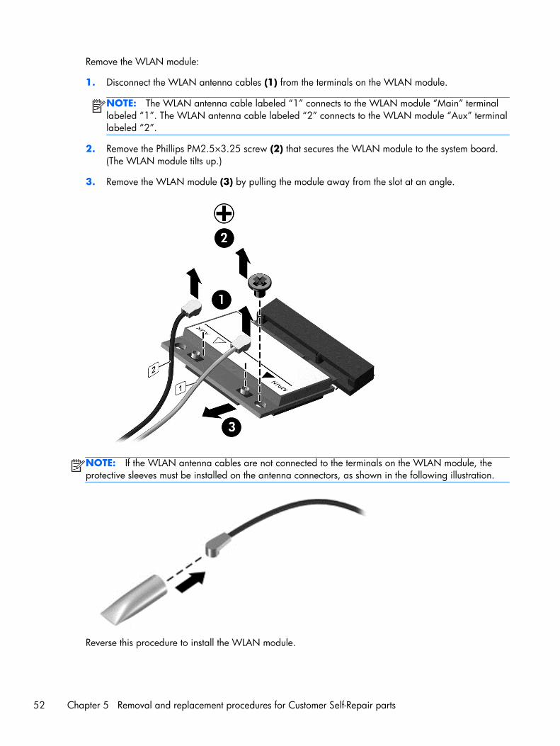
Remove the WLAN module:
1. Disconnect the WLAN antenna cables (1) from the terminals on the WLAN module.
NOTE: The WLAN antenna cable labeled “1” connects to the WLAN module “Main” terminallabeled “1”. The WLAN antenna cable labeled “2” connects to the WLAN module “Aux” terminallabeled “2”.
2. Remove the Phillips PM2.5×3.25 screw (2) that secures the WLAN module to the system board.(The WLAN module tilts up.)
3. Remove the WLAN module (3) by pulling the module away from the slot at an angle.
NOTE: If the WLAN antenna cables are not connected to the terminals on the WLAN module, theprotective sleeves must be installed on the antenna connectors, as shown in the following illustration.
Reverse this procedure to install the WLAN module.
52 Chapter 5 Removal and replacement procedures for Customer Self-Repair parts
Memory module
Description Spare part number
8-GB (PC3L, 12800, 1600-MHz) 693374-001
4-GB (PC3L, 12800, 1600-MHz) 691740-001
2-GB (PC3L, 12800, 1600-MHz) 691739-001
Update BIOS before adding memory modules
Before adding new memory, make sure you update the computer to the latest BIOS.
CAUTION: Failure to update the computer to the latest BIOS prior to installing new memory mayresult in various system problems.
To update BIOS:
1. Navigate to www.hp.com.
2. Click Support & Drivers > click Drivers & Software.
3. In the Enter a product name/number box, type the computer model information, and thenclick Search.
4. Click the link for the computer model.
5. Select the operating system, and then click Next.
6. Under Step 2: Select a Download, click the BIOS link.
7. Click the link for the most recent BIOS.
8. Click the Download button, and then follow the on-screen instructions.
Before removing a memory module, follow these steps:
1. Turn off the computer. If you are unsure whether the computer is off or in Hibernation, turn thecomputer on, and then shut it down through the operating system.
2. Disconnect the power from the computer by unplugging the power cord from the computer.
3. Disconnect all external devices from the computer.
4. Remove the battery (see Battery on page 46).
5. Remove the service cover (see Optical drive on page 47).
Remove the memory module:
1. Spread the retaining tabs (1) on each side of the memory module slot to release the memorymodule. (The memory module tilts up.)
Component replacement procedures 53
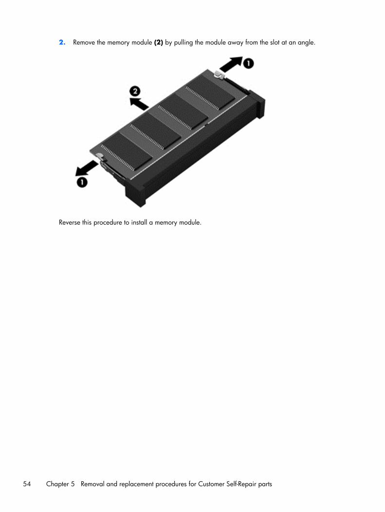
2. Remove the memory module (2) by pulling the module away from the slot at an angle.
Reverse this procedure to install a memory module.
54 Chapter 5 Removal and replacement procedures for Customer Self-Repair parts
6 Removal and replacementprocedures for Authorized ServiceProvider parts
CAUTION: Components described in this chapter should only be accessed by an authorized serviceprovider. Accessing these parts can damage the computer or void the warranty.
Component replacement proceduresThis chapter provides removal and replacement procedures for Authorized Service Provider only parts.
There are as many as 55 screws that must be removed, replaced, and/or loosened when servicing thecomputer. Make special note of each screw size and location during removal and replacement.
Component replacement procedures 55
Keyboard
NOTE: The keyboard spare part kit includes a keyboard cable.
For use in country/region Spare part number
Keyboard in black finish: For use only on computer modelsequipped with an Intel processorin Northwest Africa
719853-FP1
For use on all computer models in Belgium 719853-A41 For use on all computer modelsin Portugal
719853-131
For use on all computer modelsin Bulgaria
719853-261 For use on all computer modelsin Romania
719853-271
For use on all computer modelsin Canada
719853-DB1 For use on all computer modelsin Russia
719853-251
For use on all computer modelsin the Czech Republic and Slovakia
719853-FL1 For use only on computer modelsequipped with an Intel processorin Saudi Arabia
719853-171
For use on all computer modelsin Denmark, Finland, and Norway
719853-DH1 For use on all computer modelsin Slovenia
719853-BA1
For use on all computer models in France 719853-051 For use on all computer modelsin South Korea
719853-AD1
For use on all computer modelsin Germany
719853-041 For use on all computer modelsin Spain
719853-071
For use on all computer models in Greece 719853-151 For use on all computer modelsin Switzerland
719853-BG1
For use on all computer modelsin Hungary
719853-211 For use on all computer modelsin Taiwan
719853-AB1
For use on all computer models in Israel 719853-BB1 For use on all computer modelsin Thailand
719853-281
For use on all computer models in Italy 719853-061 For use on all computer modelsin Turkey
719853-141
For use on all computer models in Japan 719853-291 For use on all computer modelsin the United Kingdomand Singapore
719853-031
For use on all computer modelsin the Netherlands
719853-B31 For use on all computer modelsin the United States
719853-001
Keyboard in white finish: For use only on computer modelsequipped with an Intel processorin Northwest Africa
720597-FP1
For use on all computer models in Belgium 720597-A41 For use on all computer modelsin Portugal
720597-131
For use on all computer modelsin Bulgaria
720597-261 For use on all computer modelsin Romania
720597-271
56 Chapter 6 Removal and replacement procedures for Authorized Service Provider parts

For use in country/region Spare part number
For use on all computer modelsin Canada
720597-DB1 For use on all computer modelsin Russia
720597-251
For use on all computer modelsin the Czech Republic and Slovakia
720597-FL1 For use only on computer modelsequipped with an Intel processorin Saudi Arabia
720597-171
For use on all computer modelsin Denmark, Finland, and Norway
720597-DH1 For use on all computer modelsin Slovenia
720597-BA1
For use on all computer models in France 720597-051 For use on all computer modelsin South Korea
720597-AD1
For use on all computer modelsin Germany
720597-041 For use on all computer modelsin Spain
720597-071
For use on all computer models in Greece 720597-151 For use on all computer modelsin Switzerland
720597-BG1
For use on all computer modelsin Hungary
720597-211 For use on all computer modelsin Taiwan
720597-AB1
For use on all computer models in Israel 720597-BB1 For use on all computer modelsin Thailand
720597-281
For use on all computer models in Italy 720597-061 For use on all computer modelsin Turkey
720597-141
For use on all computer models in Japan 720597-291 For use on all computer modelsin the United Kingdomand Singapore
720597-031
For use on all computer modelsin the Netherlands
720597-B31 For use on all computer modelsin the United States
720597-001
Before removing the keyboard, follow these steps:
1. Turn off the computer. If you are unsure whether the computer is off or in Hibernation, turn thecomputer on, and then shut it down through the operating system.
2. Disconnect the power from the computer by unplugging the power cord from the computer.
3. Disconnect all external devices from the computer.
4. Remove the battery (see Battery on page 46).
5. Remove the service cover (see Optical drive on page 47).
6. Remove the WLAN module (see WLAN module on page 51).
Component replacement procedures 57
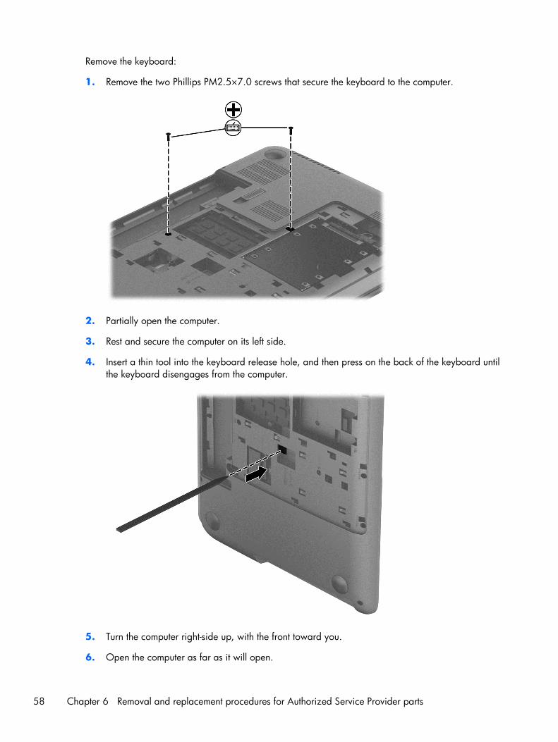
Remove the keyboard:
1. Remove the two Phillips PM2.5×7.0 screws that secure the keyboard to the computer.
2. Partially open the computer.
3. Rest and secure the computer on its left side.
4. Insert a thin tool into the keyboard release hole, and then press on the back of the keyboard untilthe keyboard disengages from the computer.
5. Turn the computer right-side up, with the front toward you.
6. Open the computer as far as it will open.
58 Chapter 6 Removal and replacement procedures for Authorized Service Provider parts
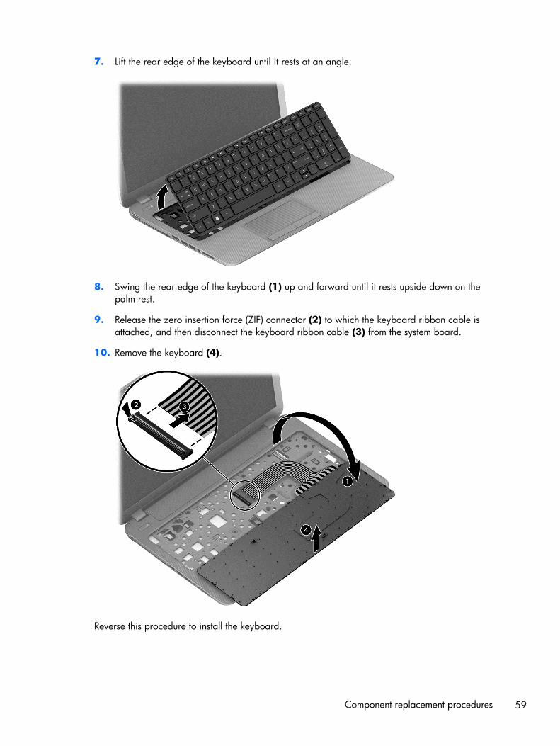
7. Lift the rear edge of the keyboard until it rests at an angle.
8. Swing the rear edge of the keyboard (1) up and forward until it rests upside down on thepalm rest.
9. Release the zero insertion force (ZIF) connector (2) to which the keyboard ribbon cable isattached, and then disconnect the keyboard ribbon cable (3) from the system board.
10. Remove the keyboard (4).
Reverse this procedure to install the keyboard.
Component replacement procedures 59
Top cover
NOTE: The top cover spare part kit includes a TouchPad.
Description Spare part number
In flying red finish 719868-001
In pearl white finish 719867-001
In regal purple finish 719870-001
In revolutionary blue finish 719869-001
In sparkling black and silver finish 719871-001
Before removing the top cover, follow these steps:
1. Turn off the computer. If you are unsure whether the computer is off or in Hibernation, turn thecomputer on, and then shut it down through the operating system.
2. Disconnect the power from the computer by unplugging the power cord from the computer.
3. Disconnect all external devices from the computer.
4. Remove the battery (see Battery on page 46), and then remove the following components:
a. Optical drive (see Optical drive on page 47)
b. Hard drive (see Hard drive on page 49)
c. Keyboard (see Keyboard on page 56)
NOTE: When replacing the top cover, be sure to remove the following components from the defectivetop cover and install them on the replacement top cover:
● Power button board (see Power button board on page 64)
● TouchPad button board (see TouchPad button board on page 65)
Remove the top cover:
1. Close the computer.
2. Turn the computer upside down with the front toward you.
60 Chapter 6 Removal and replacement procedures for Authorized Service Provider parts
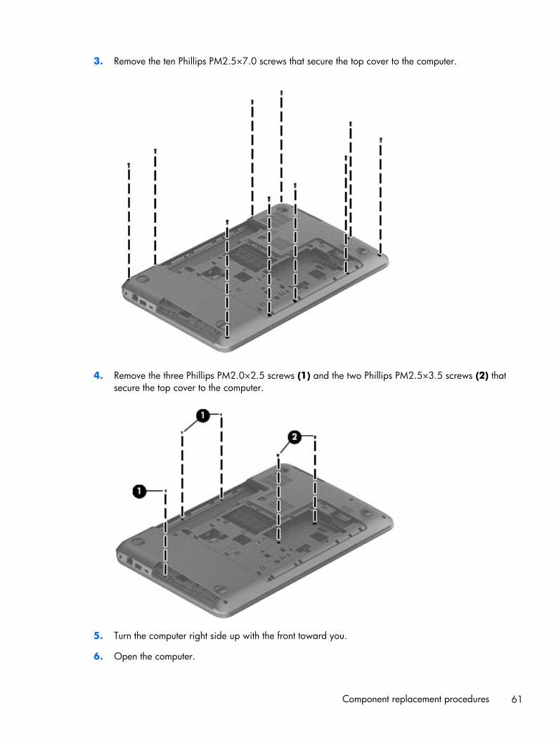
3. Remove the ten Phillips PM2.5×7.0 screws that secure the top cover to the computer.
4. Remove the three Phillips PM2.0×2.5 screws (1) and the two Phillips PM2.5×3.5 screws (2) thatsecure the top cover to the computer.
5. Turn the computer right side up with the front toward you.
6. Open the computer.
Component replacement procedures 61
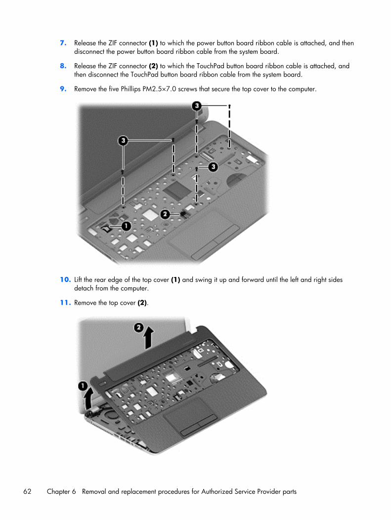
7. Release the ZIF connector (1) to which the power button board ribbon cable is attached, and thendisconnect the power button board ribbon cable from the system board.
8. Release the ZIF connector (2) to which the TouchPad button board ribbon cable is attached, andthen disconnect the TouchPad button board ribbon cable from the system board.
9. Remove the five Phillips PM2.5×7.0 screws that secure the top cover to the computer.
10. Lift the rear edge of the top cover (1) and swing it up and forward until the left and right sidesdetach from the computer.
11. Remove the top cover (2).
62 Chapter 6 Removal and replacement procedures for Authorized Service Provider parts

Reverse this procedure to install the top cover.
Component replacement procedures 63
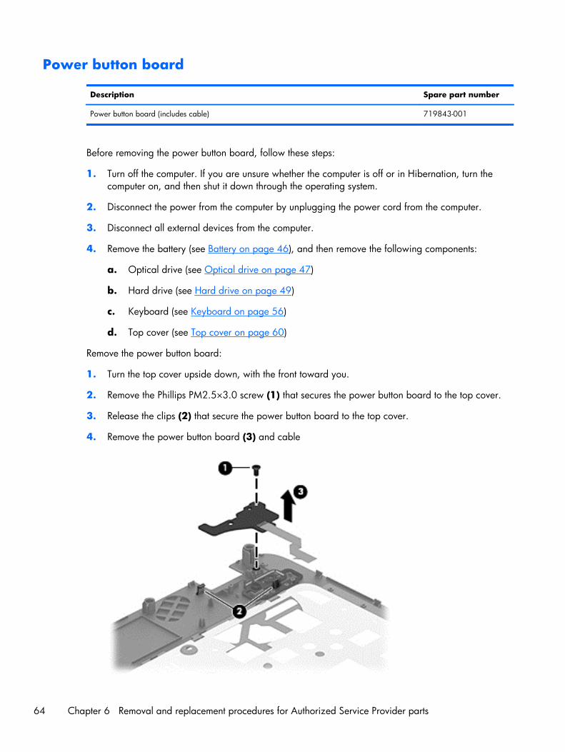
Power button board
Description Spare part number
Power button board (includes cable) 719843-001
Before removing the power button board, follow these steps:
1. Turn off the computer. If you are unsure whether the computer is off or in Hibernation, turn thecomputer on, and then shut it down through the operating system.
2. Disconnect the power from the computer by unplugging the power cord from the computer.
3. Disconnect all external devices from the computer.
4. Remove the battery (see Battery on page 46), and then remove the following components:
a. Optical drive (see Optical drive on page 47)
b. Hard drive (see Hard drive on page 49)
c. Keyboard (see Keyboard on page 56)
d. Top cover (see Top cover on page 60)
Remove the power button board:
1. Turn the top cover upside down, with the front toward you.
2. Remove the Phillips PM2.5×3.0 screw (1) that secures the power button board to the top cover.
3. Release the clips (2) that secure the power button board to the top cover.
4. Remove the power button board (3) and cable
64 Chapter 6 Removal and replacement procedures for Authorized Service Provider parts
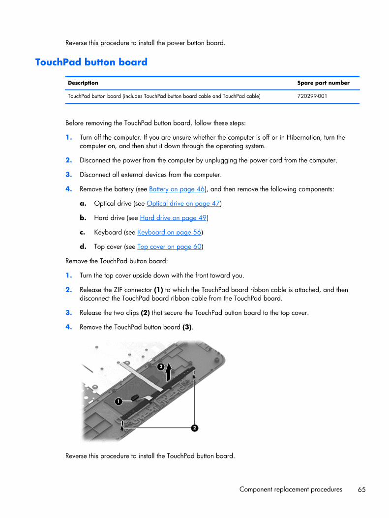
Reverse this procedure to install the power button board.
TouchPad button board
Description Spare part number
TouchPad button board (includes TouchPad button board cable and TouchPad cable) 720299-001
Before removing the TouchPad button board, follow these steps:
1. Turn off the computer. If you are unsure whether the computer is off or in Hibernation, turn thecomputer on, and then shut it down through the operating system.
2. Disconnect the power from the computer by unplugging the power cord from the computer.
3. Disconnect all external devices from the computer.
4. Remove the battery (see Battery on page 46), and then remove the following components:
a. Optical drive (see Optical drive on page 47)
b. Hard drive (see Hard drive on page 49)
c. Keyboard (see Keyboard on page 56)
d. Top cover (see Top cover on page 60)
Remove the TouchPad button board:
1. Turn the top cover upside down with the front toward you.
2. Release the ZIF connector (1) to which the TouchPad board ribbon cable is attached, and thendisconnect the TouchPad board ribbon cable from the TouchPad board.
3. Release the two clips (2) that secure the TouchPad button board to the top cover.
4. Remove the TouchPad button board (3).
Reverse this procedure to install the TouchPad button board.
Component replacement procedures 65
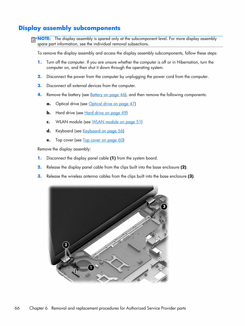
Display assembly subcomponents
NOTE: The display assembly is spared only at the subcomponent level. For more display assemblyspare part information, see the individual removal subsections.
To remove the display assembly and access the display assembly subcomponents, follow these steps:
1. Turn off the computer. If you are unsure whether the computer is off or in Hibernation, turn thecomputer on, and then shut it down through the operating system.
2. Disconnect the power from the computer by unplugging the power cord from the computer.
3. Disconnect all external devices from the computer.
4. Remove the battery (see Battery on page 46), and then remove the following components:
a. Optical drive (see Optical drive on page 47)
b. Hard drive (see Hard drive on page 49)
c. WLAN module (see WLAN module on page 51)
d. Keyboard (see Keyboard on page 56)
e. Top cover (see Top cover on page 60)
Remove the display assembly:
1. Disconnect the display panel cable (1) from the system board.
2. Release the display panel cable from the clips built into the base enclosure (2).
3. Release the wireless antenna cables from the clips built into the base enclosure (3).
66 Chapter 6 Removal and replacement procedures for Authorized Service Provider parts
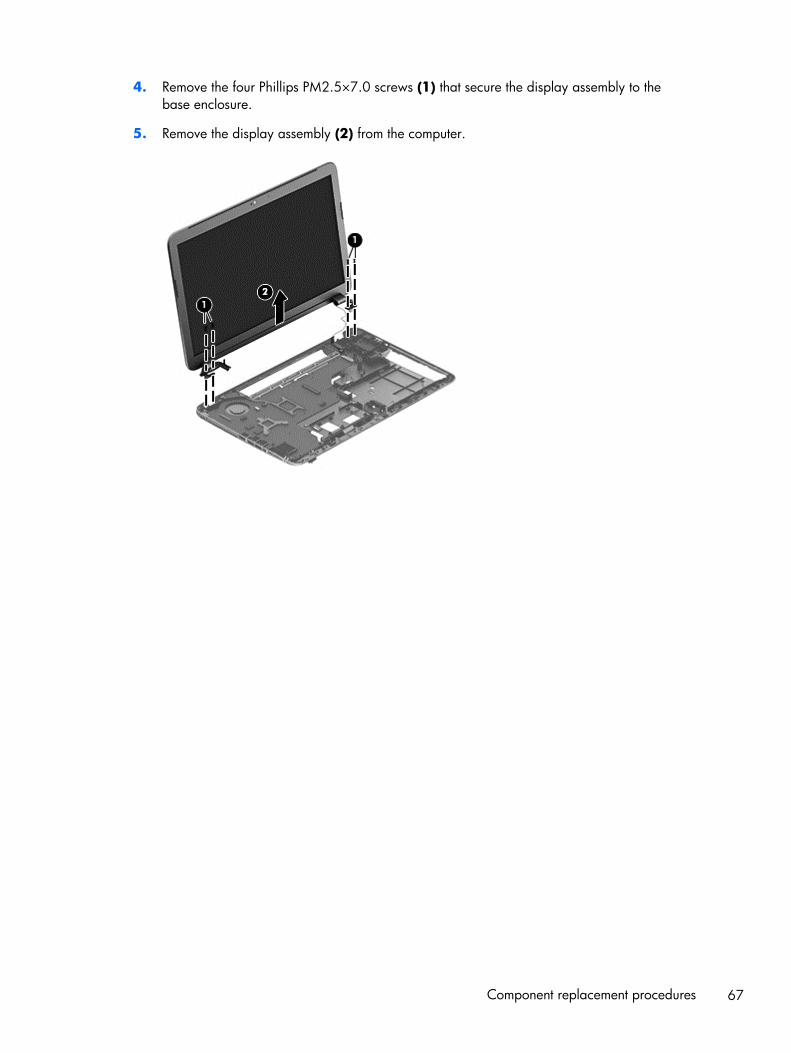
4. Remove the four Phillips PM2.5×7.0 screws (1) that secure the display assembly to thebase enclosure.
5. Remove the display assembly (2) from the computer.
Component replacement procedures 67
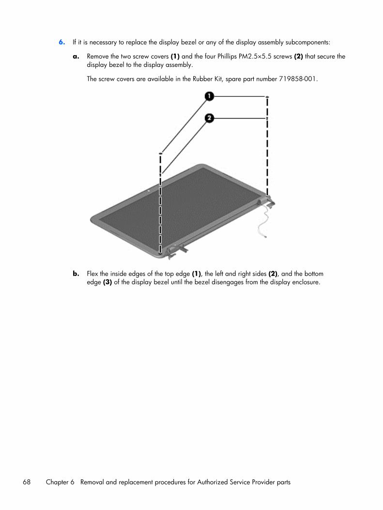
6. If it is necessary to replace the display bezel or any of the display assembly subcomponents:
a. Remove the two screw covers (1) and the four Phillips PM2.5×5.5 screws (2) that secure thedisplay bezel to the display assembly.
The screw covers are available in the Rubber Kit, spare part number 719858-001.
b. Flex the inside edges of the top edge (1), the left and right sides (2), and the bottomedge (3) of the display bezel until the bezel disengages from the display enclosure.
68 Chapter 6 Removal and replacement procedures for Authorized Service Provider parts
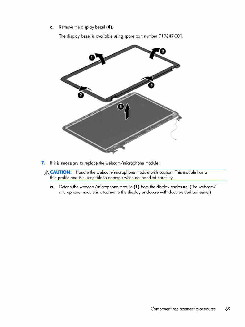
c. Remove the display bezel (4).
The display bezel is available using spare part number 719847-001.
7. If it is necessary to replace the webcam/microphone module:
CAUTION: Handle the webcam/microphone module with caution. This module has athin profile and is susceptible to damage when not handled carefully.
a. Detach the webcam/microphone module (1) from the display enclosure. (The webcam/microphone module is attached to the display enclosure with double-sided adhesive.)
Component replacement procedures 69
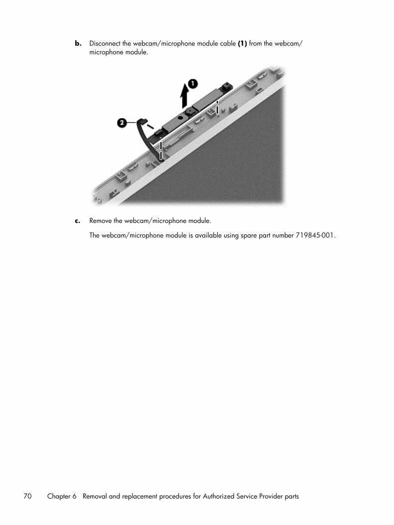
b. Disconnect the webcam/microphone module cable (1) from the webcam/microphone module.
c. Remove the webcam/microphone module.
The webcam/microphone module is available using spare part number 719845-001.
70 Chapter 6 Removal and replacement procedures for Authorized Service Provider parts
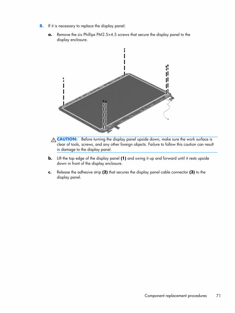
8. If it is necessary to replace the display panel:
a. Remove the six Phillips PM2.5×4.5 screws that secure the display panel to thedisplay enclosure.
CAUTION: Before turning the display panel upside down, make sure the work surface isclear of tools, screws, and any other foreign objects. Failure to follow this caution can resultin damage to the display panel.
b. Lift the top edge of the display panel (1) and swing it up and forward until it rests upsidedown in front of the display enclosure.
c. Release the adhesive strip (2) that secures the display panel cable connector (3) to thedisplay panel.
Component replacement procedures 71
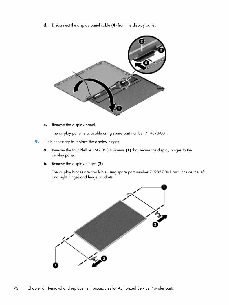
d. Disconnect the display panel cable (4) from the display panel.
e. Remove the display panel.
The display panel is available using spare part number 719873-001.
9. If it is necessary to replace the display hinges:
a. Remove the four Phillips PM2.0×3.0 screws (1) that secure the display hinges to thedisplay panel.
b. Remove the display hinges (2).
The display hinges are available using spare part number 719857-001 and include the leftand right hinges and hinge brackets.
72 Chapter 6 Removal and replacement procedures for Authorized Service Provider parts
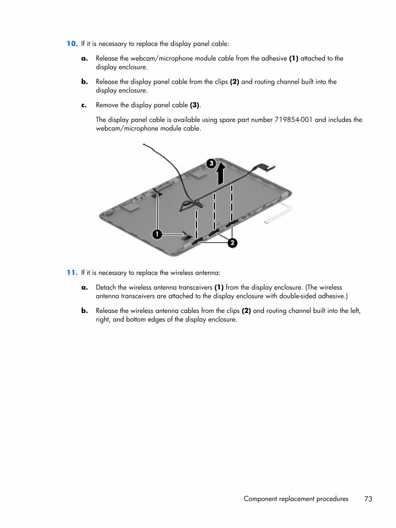
10. If it is necessary to replace the display panel cable:
a. Release the webcam/microphone module cable from the adhesive (1) attached to thedisplay enclosure.
b. Release the display panel cable from the clips (2) and routing channel built into thedisplay enclosure.
c. Remove the display panel cable (3).
The display panel cable is available using spare part number 719854-001 and includes thewebcam/microphone module cable.
11. If it is necessary to replace the wireless antenna:
a. Detach the wireless antenna transceivers (1) from the display enclosure. (The wirelessantenna transceivers are attached to the display enclosure with double-sided adhesive.)
b. Release the wireless antenna cables from the clips (2) and routing channel built into the left,right, and bottom edges of the display enclosure.
Component replacement procedures 73
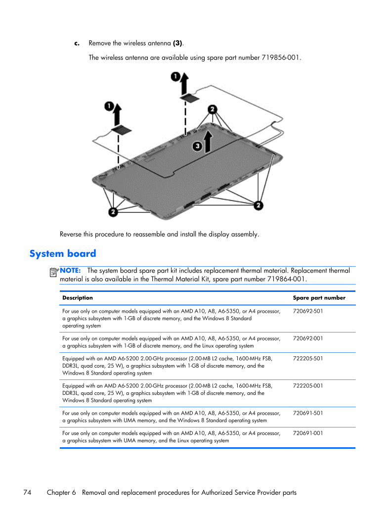
c. Remove the wireless antenna (3).
The wireless antenna are available using spare part number 719856-001.
Reverse this procedure to reassemble and install the display assembly.
System board
NOTE: The system board spare part kit includes replacement thermal material. Replacement thermalmaterial is also available in the Thermal Material Kit, spare part number 719864-001.
Description Spare part number
For use only on computer models equipped with an AMD A10, A8, A6-5350, or A4 processor,a graphics subsystem with 1-GB of discrete memory, and the Windows 8 Standardoperating system
720692-501
For use only on computer models equipped with an AMD A10, A8, A6-5350, or A4 processor,a graphics subsystem with 1-GB of discrete memory, and the Linux operating system
720692-001
Equipped with an AMD A6-5200 2.00-GHz processor (2.00-MB L2 cache, 1600-MHz FSB,DDR3L, quad core, 25 W), a graphics subsystem with 1-GB of discrete memory, and theWindows 8 Standard operating system
722205-501
Equipped with an AMD A6-5200 2.00-GHz processor (2.00-MB L2 cache, 1600-MHz FSB,DDR3L, quad core, 25 W), a graphics subsystem with 1-GB of discrete memory, and theWindows 8 Standard operating system
722205-001
For use only on computer models equipped with an AMD A10, A8, A6-5350, or A4 processor,a graphics subsystem with UMA memory, and the Windows 8 Standard operating system
720691-501
For use only on computer models equipped with an AMD A10, A8, A6-5350, or A4 processor,a graphics subsystem with UMA memory, and the Linux operating system
720691-001
74 Chapter 6 Removal and replacement procedures for Authorized Service Provider parts
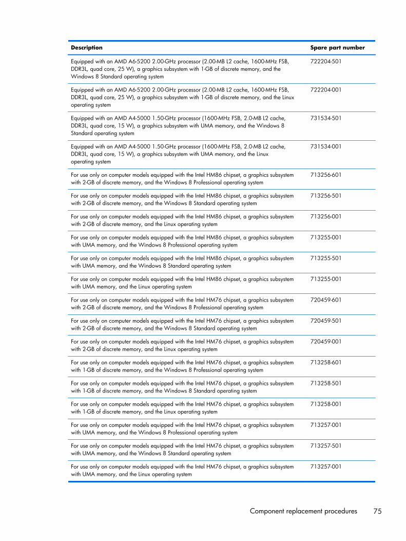
Description Spare part number
Equipped with an AMD A6-5200 2.00-GHz processor (2.00-MB L2 cache, 1600-MHz FSB,DDR3L, quad core, 25 W), a graphics subsystem with 1-GB of discrete memory, and theWindows 8 Standard operating system
722204-501
Equipped with an AMD A6-5200 2.00-GHz processor (2.00-MB L2 cache, 1600-MHz FSB,DDR3L, quad core, 25 W), a graphics subsystem with 1-GB of discrete memory, and the Linuxoperating system
722204-001
Equipped with an AMD A4-5000 1.50-GHz processor (1600-MHz FSB, 2.0-MB L2 cache,DDR3L, quad core, 15 W), a graphics subsystem with UMA memory, and the Windows 8Standard operating system
731534-501
Equipped with an AMD A4-5000 1.50-GHz processor (1600-MHz FSB, 2.0-MB L2 cache,DDR3L, quad core, 15 W), a graphics subsystem with UMA memory, and the Linuxoperating system
731534-001
For use only on computer models equipped with the Intel HM86 chipset, a graphics subsystemwith 2-GB of discrete memory, and the Windows 8 Professional operating system
713256-601
For use only on computer models equipped with the Intel HM86 chipset, a graphics subsystemwith 2-GB of discrete memory, and the Windows 8 Standard operating system
713256-501
For use only on computer models equipped with the Intel HM86 chipset, a graphics subsystemwith 2-GB of discrete memory, and the Linux operating system
713256-001
For use only on computer models equipped with the Intel HM86 chipset, a graphics subsystemwith UMA memory, and the Windows 8 Professional operating system
713255-001
For use only on computer models equipped with the Intel HM86 chipset, a graphics subsystemwith UMA memory, and the Windows 8 Standard operating system
713255-501
For use only on computer models equipped with the Intel HM86 chipset, a graphics subsystemwith UMA memory, and the Linux operating system
713255-001
For use only on computer models equipped with the Intel HM76 chipset, a graphics subsystemwith 2-GB of discrete memory, and the Windows 8 Professional operating system
720459-601
For use only on computer models equipped with the Intel HM76 chipset, a graphics subsystemwith 2-GB of discrete memory, and the Windows 8 Standard operating system
720459-501
For use only on computer models equipped with the Intel HM76 chipset, a graphics subsystemwith 2-GB of discrete memory, and the Linux operating system
720459-001
For use only on computer models equipped with the Intel HM76 chipset, a graphics subsystemwith 1-GB of discrete memory, and the Windows 8 Professional operating system
713258-601
For use only on computer models equipped with the Intel HM76 chipset, a graphics subsystemwith 1-GB of discrete memory, and the Windows 8 Standard operating system
713258-501
For use only on computer models equipped with the Intel HM76 chipset, a graphics subsystemwith 1-GB of discrete memory, and the Linux operating system
713258-001
For use only on computer models equipped with the Intel HM76 chipset, a graphics subsystemwith UMA memory, and the Windows 8 Professional operating system
713257-001
For use only on computer models equipped with the Intel HM76 chipset, a graphics subsystemwith UMA memory, and the Windows 8 Standard operating system
713257-501
For use only on computer models equipped with the Intel HM76 chipset, a graphics subsystemwith UMA memory, and the Linux operating system
713257-001
Component replacement procedures 75
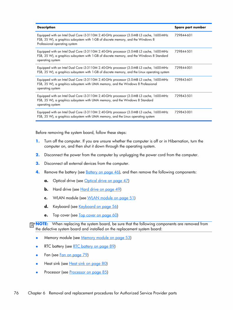
Description Spare part number
Equipped with an Intel Dual Core i3-3110M 2.40-GHz processor (3.0-MB L3 cache, 1600-MHzFSB, 35 W), a graphics subsystem with 1-GB of discrete memory, and the Windows 8Professional operating system
729844-601
Equipped with an Intel Dual Core i3-3110M 2.40-GHz processor (3.0-MB L3 cache, 1600-MHzFSB, 35 W), a graphics subsystem with 1-GB of discrete memory, and the Windows 8 Standardoperating system
729844-501
Equipped with an Intel Dual Core i3-3110M 2.40-GHz processor (3.0-MB L3 cache, 1600-MHzFSB, 35 W), a graphics subsystem with 1-GB of discrete memory, and the Linux operating system
729844-001
Equipped with an Intel Dual Core i3-3110M 2.40-GHz processor (3.0-MB L3 cache, 1600-MHzFSB, 35 W), a graphics subsystem with UMA memory, and the Windows 8 Professionaloperating system
729843-601
Equipped with an Intel Dual Core i3-3110M 2.40-GHz processor (3.0-MB L3 cache, 1600-MHzFSB, 35 W), a graphics subsystem with UMA memory, and the Windows 8 Standardoperating system
729843-501
Equipped with an Intel Dual Core i3-3110M 2.40-GHz processor (3.0-MB L3 cache, 1600-MHzFSB, 35 W), a graphics subsystem with UMA memory, and the Linux operating system
729843-001
Before removing the system board, follow these steps:
1. Turn off the computer. If you are unsure whether the computer is off or in Hibernation, turn thecomputer on, and then shut it down through the operating system.
2. Disconnect the power from the computer by unplugging the power cord from the computer.
3. Disconnect all external devices from the computer.
4. Remove the battery (see Battery on page 46), and then remove the following components:
a. Optical drive (see Optical drive on page 47)
b. Hard drive (see Hard drive on page 49)
c. WLAN module (see WLAN module on page 51)
d. Keyboard (see Keyboard on page 56)
e. Top cover (see Top cover on page 60)
NOTE: When replacing the system board, be sure that the following components are removed fromthe defective system board and installed on the replacement system board:
● Memory module (see Memory module on page 53)
● RTC battery (see RTC battery on page 89)
● Fan (see Fan on page 79)
● Heat sink (see Heat sink on page 80)
● Processor (see Processor on page 85)
76 Chapter 6 Removal and replacement procedures for Authorized Service Provider parts
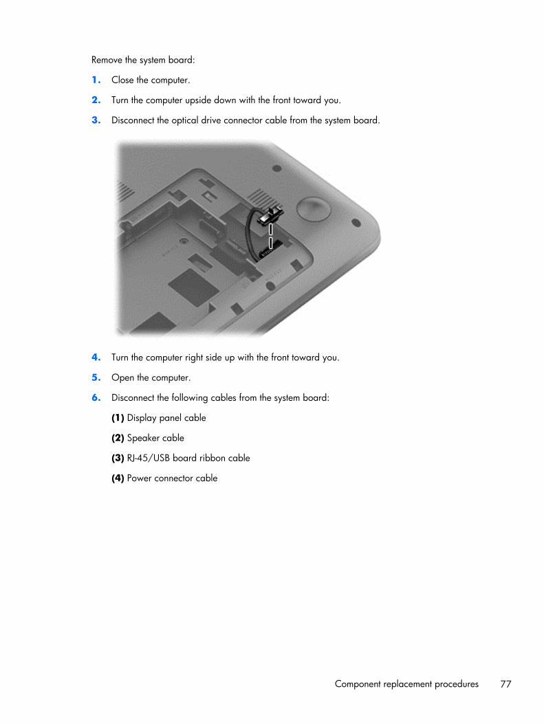
Remove the system board:
1. Close the computer.
2. Turn the computer upside down with the front toward you.
3. Disconnect the optical drive connector cable from the system board.
4. Turn the computer right side up with the front toward you.
5. Open the computer.
6. Disconnect the following cables from the system board:
(1) Display panel cable
(2) Speaker cable
(3) RJ-45/USB board ribbon cable
(4) Power connector cable
Component replacement procedures 77
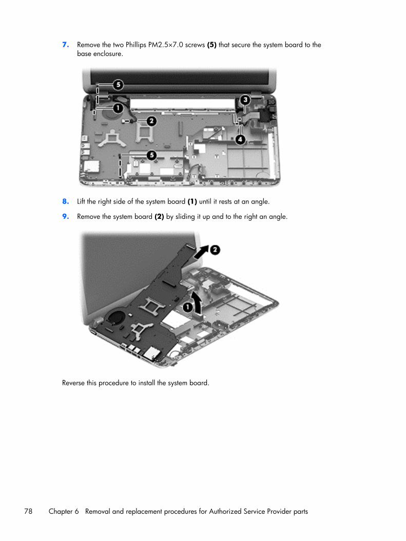
7. Remove the two Phillips PM2.5×7.0 screws (5) that secure the system board to thebase enclosure.
8. Lift the right side of the system board (1) until it rests at an angle.
9. Remove the system board (2) by sliding it up and to the right an angle.
Reverse this procedure to install the system board.
78 Chapter 6 Removal and replacement procedures for Authorized Service Provider parts
Fan
Description Spare part number
Fan (includes cable) 719860-001
Before removing the fan, follow these steps:
1. Turn off the computer. If you are unsure whether the computer is off or in Hibernation, turn thecomputer on, and then shut it down through the operating system.
2. Disconnect the power from the computer by unplugging the power cord from the computer.
3. Disconnect all external devices from the computer.
4. Remove the battery (see Battery on page 46), and then remove the following components:
a. Optical drive (see Optical drive on page 47)
b. Hard drive (see Hard drive on page 49)
c. WLAN module (see WLAN module on page 51)
d. Keyboard (see Keyboard on page 56)
e. Top cover (see Top cover on page 60)
f. System board (see System board on page 74)
Remove the fan:
1. Turn the system board upside down with the front toward you.
2. Disconnect the fan cable (1) from the system board.
3. Remove the Phillips PM2.0×5.0 screw (2) that secures the fan to the system board.
Component replacement procedures 79
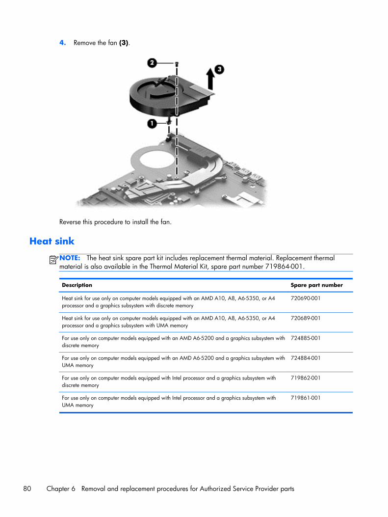
4. Remove the fan (3).
Reverse this procedure to install the fan.
Heat sink
NOTE: The heat sink spare part kit includes replacement thermal material. Replacement thermalmaterial is also available in the Thermal Material Kit, spare part number 719864-001.
Description Spare part number
Heat sink for use only on computer models equipped with an AMD A10, A8, A6-5350, or A4processor and a graphics subsystem with discrete memory
720690-001
Heat sink for use only on computer models equipped with an AMD A10, A8, A6-5350, or A4processor and a graphics subsystem with UMA memory
720689-001
For use only on computer models equipped with an AMD A6-5200 and a graphics subsystem withdiscrete memory
724885-001
For use only on computer models equipped with an AMD A6-5200 and a graphics subsystem withUMA memory
724884-001
For use only on computer models equipped with Intel processor and a graphics subsystem withdiscrete memory
719862-001
For use only on computer models equipped with Intel processor and a graphics subsystem withUMA memory
719861-001
80 Chapter 6 Removal and replacement procedures for Authorized Service Provider parts
Before removing the heat sink, follow these steps:
1. Turn off the computer. If you are unsure whether the computer is off or in Hibernation, turn thecomputer on, and then shut it down through the operating system.
2. Disconnect the power from the computer by unplugging the power cord from the computer.
3. Disconnect all external devices from the computer.
4. Remove the battery (see Battery on page 46), and then remove the following components:
a. Optical drive (see Optical drive on page 47)
b. Hard drive (see Hard drive on page 49)
c. WLAN module (see WLAN module on page 51)
d. Keyboard (see Keyboard on page 56)
e. Top cover (see Top cover on page 60)
f. System board (see System board on page 74)
g. Fan (see Fan on page 79)
Remove the heat sink:
1. Turn the system board upside down, with the front toward you.
NOTE: Steps 2 and 3 apply to computer models equipped with a graphics subsystem withdiscrete memory.
2. Following the 1 through 7 sequence stamped into the heat sink, loosen the seven captive Phillipsscrews (1) that secure the heat sink to the system board.
Component replacement procedures 81
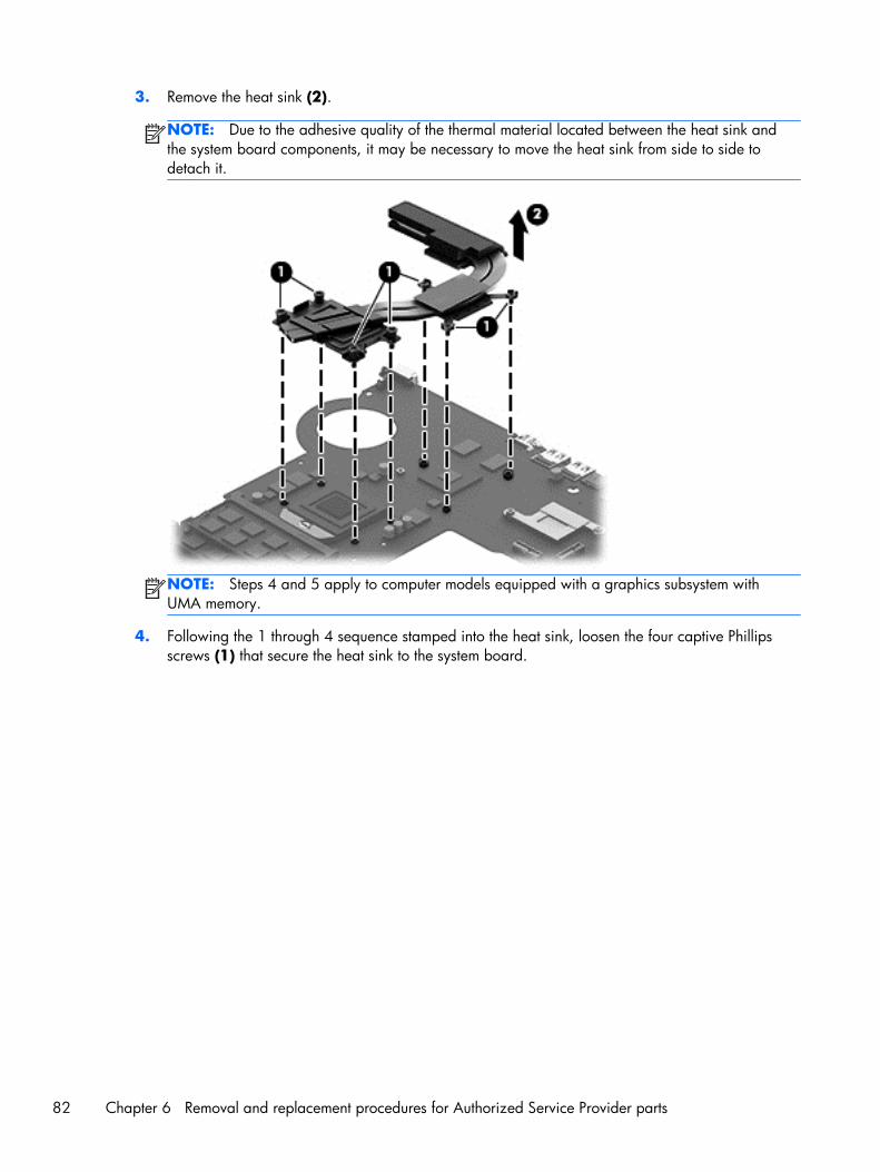
3. Remove the heat sink (2).
NOTE: Due to the adhesive quality of the thermal material located between the heat sink andthe system board components, it may be necessary to move the heat sink from side to side todetach it.
NOTE: Steps 4 and 5 apply to computer models equipped with a graphics subsystem withUMA memory.
4. Following the 1 through 4 sequence stamped into the heat sink, loosen the four captive Phillipsscrews (1) that secure the heat sink to the system board.
82 Chapter 6 Removal and replacement procedures for Authorized Service Provider parts
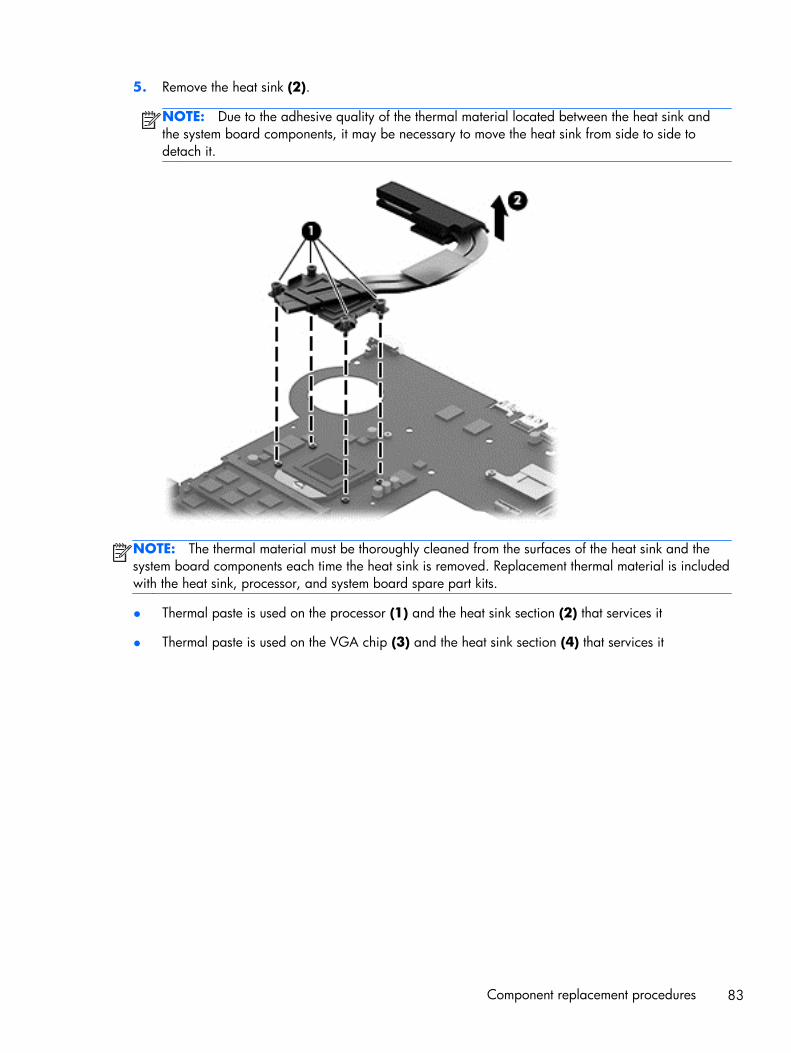
5. Remove the heat sink (2).
NOTE: Due to the adhesive quality of the thermal material located between the heat sink andthe system board components, it may be necessary to move the heat sink from side to side todetach it.
NOTE: The thermal material must be thoroughly cleaned from the surfaces of the heat sink and thesystem board components each time the heat sink is removed. Replacement thermal material is includedwith the heat sink, processor, and system board spare part kits.
● Thermal paste is used on the processor (1) and the heat sink section (2) that services it
● Thermal paste is used on the VGA chip (3) and the heat sink section (4) that services it
Component replacement procedures 83
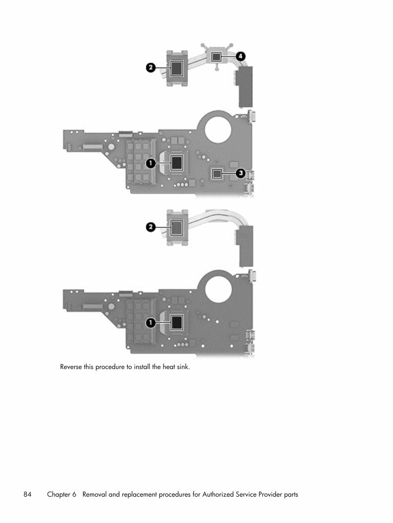
Reverse this procedure to install the heat sink.
84 Chapter 6 Removal and replacement procedures for Authorized Service Provider parts
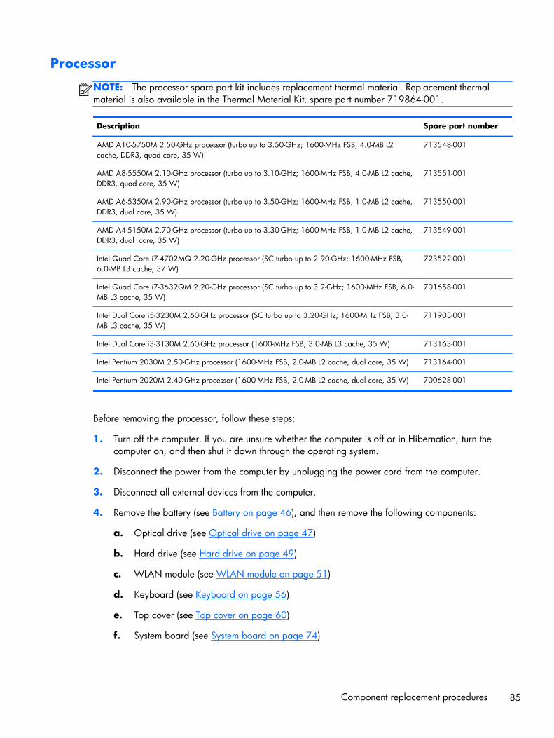
Processor
NOTE: The processor spare part kit includes replacement thermal material. Replacement thermalmaterial is also available in the Thermal Material Kit, spare part number 719864-001.
Description Spare part number
AMD A10-5750M 2.50-GHz processor (turbo up to 3.50-GHz; 1600-MHz FSB, 4.0-MB L2cache, DDR3, quad core, 35 W)
713548-001
AMD A8-5550M 2.10-GHz processor (turbo up to 3.10-GHz; 1600-MHz FSB, 4.0-MB L2 cache,DDR3, quad core, 35 W)
713551-001
AMD A6-5350M 2.90-GHz processor (turbo up to 3.50-GHz; 1600-MHz FSB, 1.0-MB L2 cache,DDR3, dual core, 35 W)
713550-001
AMD A4-5150M 2.70-GHz processor (turbo up to 3.30-GHz; 1600-MHz FSB, 1.0-MB L2 cache,DDR3, dual core, 35 W)
713549-001
Intel Quad Core i7-4702MQ 2.20-GHz processor (SC turbo up to 2.90-GHz; 1600-MHz FSB,6.0-MB L3 cache, 37 W)
723522-001
Intel Quad Core i7-3632QM 2.20-GHz processor (SC turbo up to 3.2-GHz; 1600-MHz FSB, 6.0-MB L3 cache, 35 W)
701658-001
Intel Dual Core i5-3230M 2.60-GHz processor (SC turbo up to 3.20-GHz; 1600-MHz FSB, 3.0-MB L3 cache, 35 W)
711903-001
Intel Dual Core i3-3130M 2.60-GHz processor (1600-MHz FSB, 3.0-MB L3 cache, 35 W) 713163-001
Intel Pentium 2030M 2.50-GHz processor (1600-MHz FSB, 2.0-MB L2 cache, dual core, 35 W) 713164-001
Intel Pentium 2020M 2.40-GHz processor (1600-MHz FSB, 2.0-MB L2 cache, dual core, 35 W) 700628-001
Before removing the processor, follow these steps:
1. Turn off the computer. If you are unsure whether the computer is off or in Hibernation, turn thecomputer on, and then shut it down through the operating system.
2. Disconnect the power from the computer by unplugging the power cord from the computer.
3. Disconnect all external devices from the computer.
4. Remove the battery (see Battery on page 46), and then remove the following components:
a. Optical drive (see Optical drive on page 47)
b. Hard drive (see Hard drive on page 49)
c. WLAN module (see WLAN module on page 51)
d. Keyboard (see Keyboard on page 56)
e. Top cover (see Top cover on page 60)
f. System board (see System board on page 74)
Component replacement procedures 85
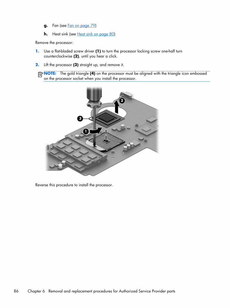
g. Fan (see Fan on page 79)
h. Heat sink (see Heat sink on page 80)
Remove the processor:
1. Use a flat-bladed screw driver (1) to turn the processor locking screw one-half turncounterclockwise (2), until you hear a click.
2. Lift the processor (3) straight up, and remove it.
NOTE: The gold triangle (4) on the processor must be aligned with the triangle icon embossedon the processor socket when you install the processor.
Reverse this procedure to install the processor.
86 Chapter 6 Removal and replacement procedures for Authorized Service Provider parts
PCH heat sink
NOTE: The post controller hub (PCH) heat sink spare part kit includes replacement thermal material.Replacement thermal material is also available in the Thermal Material Kit, spare part number719864-001.
Description Spare part number
PCH heat sink 719863-001
Before removing the PCH heat sink, follow these steps:
1. Turn off the computer. If you are unsure whether the computer is off or in Hibernation, turn thecomputer on, and then shut it down through the operating system.
2. Disconnect the power from the computer by unplugging the power cord from the computer.
3. Disconnect all external devices from the computer.
4. Remove the battery (see Battery on page 46), and then remove the following components:
a. Optical drive (see Optical drive on page 47)
b. Hard drive (see Hard drive on page 49)
c. WLAN module (see WLAN module on page 51)
d. Keyboard (see Keyboard on page 56)
e. Top cover (see Top cover on page 60)
f. System board (see System board on page 74)
Remove the PCH heat sink:
1. Following the 1 through 2 sequence stamped into the PCH heat sink, loosen the two captivePhillips screws (1) that secure the PCH heat sink to the system board.
Component replacement procedures 87
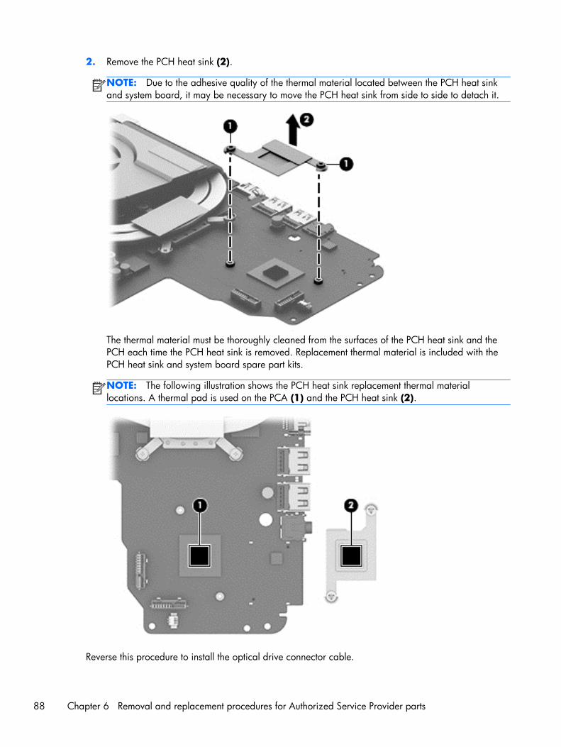
2. Remove the PCH heat sink (2).
NOTE: Due to the adhesive quality of the thermal material located between the PCH heat sinkand system board, it may be necessary to move the PCH heat sink from side to side to detach it.
The thermal material must be thoroughly cleaned from the surfaces of the PCH heat sink and thePCH each time the PCH heat sink is removed. Replacement thermal material is included with thePCH heat sink and system board spare part kits.
NOTE: The following illustration shows the PCH heat sink replacement thermal materiallocations. A thermal pad is used on the PCA (1) and the PCH heat sink (2).
Reverse this procedure to install the optical drive connector cable.
88 Chapter 6 Removal and replacement procedures for Authorized Service Provider parts
RTC battery
Description Spare part number
RTC battery (includes double-sided tape) 637193-001
Before removing the RTC battery, follow these steps:
1. Turn off the computer. If you are unsure whether the computer is off or in Hibernation, turn thecomputer on, and then shut it down through the operating system.
2. Disconnect the power from the computer by unplugging the power cord from the computer.
3. Disconnect all external devices from the computer.
4. Remove the battery (see Battery on page 46), and then remove the following components:
a. Optical drive (see Optical drive on page 47)
b. Hard drive (see Hard drive on page 49)
c. WLAN module (see WLAN module on page 51)
d. Keyboard (see Keyboard on page 56)
e. Top cover (see Top cover on page 60)
f. System board (see System board on page 74)
Remove the RTC battery:
1. Turn the system board upside down with the front toward you.
2. Disconnect the RTC battery cable (1) from the system board.
Component replacement procedures 89
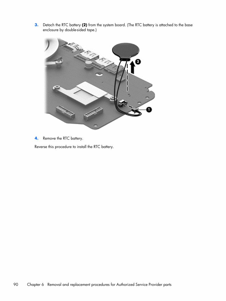
3. Detach the RTC battery (2) from the system board. (The RTC battery is attached to the baseenclosure by double-sided tape.)
4. Remove the RTC battery.
Reverse this procedure to install the RTC battery.
90 Chapter 6 Removal and replacement procedures for Authorized Service Provider parts
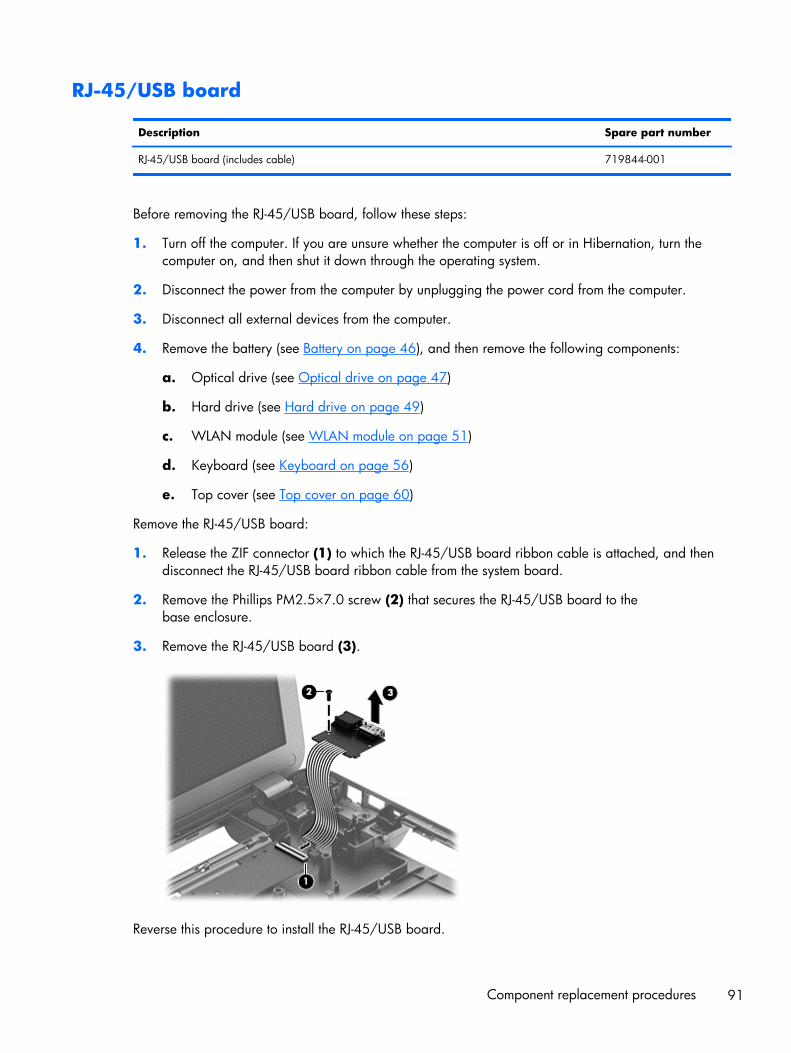
RJ-45/USB board
Description Spare part number
RJ-45/USB board (includes cable) 719844-001
Before removing the RJ-45/USB board, follow these steps:
1. Turn off the computer. If you are unsure whether the computer is off or in Hibernation, turn thecomputer on, and then shut it down through the operating system.
2. Disconnect the power from the computer by unplugging the power cord from the computer.
3. Disconnect all external devices from the computer.
4. Remove the battery (see Battery on page 46), and then remove the following components:
a. Optical drive (see Optical drive on page 47)
b. Hard drive (see Hard drive on page 49)
c. WLAN module (see WLAN module on page 51)
d. Keyboard (see Keyboard on page 56)
e. Top cover (see Top cover on page 60)
Remove the RJ-45/USB board:
1. Release the ZIF connector (1) to which the RJ-45/USB board ribbon cable is attached, and thendisconnect the RJ-45/USB board ribbon cable from the system board.
2. Remove the Phillips PM2.5×7.0 screw (2) that secures the RJ-45/USB board to thebase enclosure.
3. Remove the RJ-45/USB board (3).
Reverse this procedure to install the RJ-45/USB board.
Component replacement procedures 91
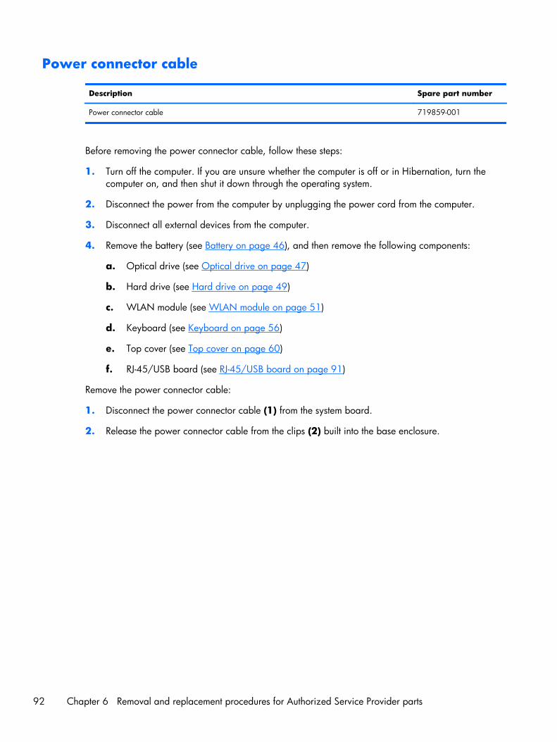
Power connector cable
Description Spare part number
Power connector cable 719859-001
Before removing the power connector cable, follow these steps:
1. Turn off the computer. If you are unsure whether the computer is off or in Hibernation, turn thecomputer on, and then shut it down through the operating system.
2. Disconnect the power from the computer by unplugging the power cord from the computer.
3. Disconnect all external devices from the computer.
4. Remove the battery (see Battery on page 46), and then remove the following components:
a. Optical drive (see Optical drive on page 47)
b. Hard drive (see Hard drive on page 49)
c. WLAN module (see WLAN module on page 51)
d. Keyboard (see Keyboard on page 56)
e. Top cover (see Top cover on page 60)
f. RJ-45/USB board (see RJ-45/USB board on page 91)
Remove the power connector cable:
1. Disconnect the power connector cable (1) from the system board.
2. Release the power connector cable from the clips (2) built into the base enclosure.
92 Chapter 6 Removal and replacement procedures for Authorized Service Provider parts
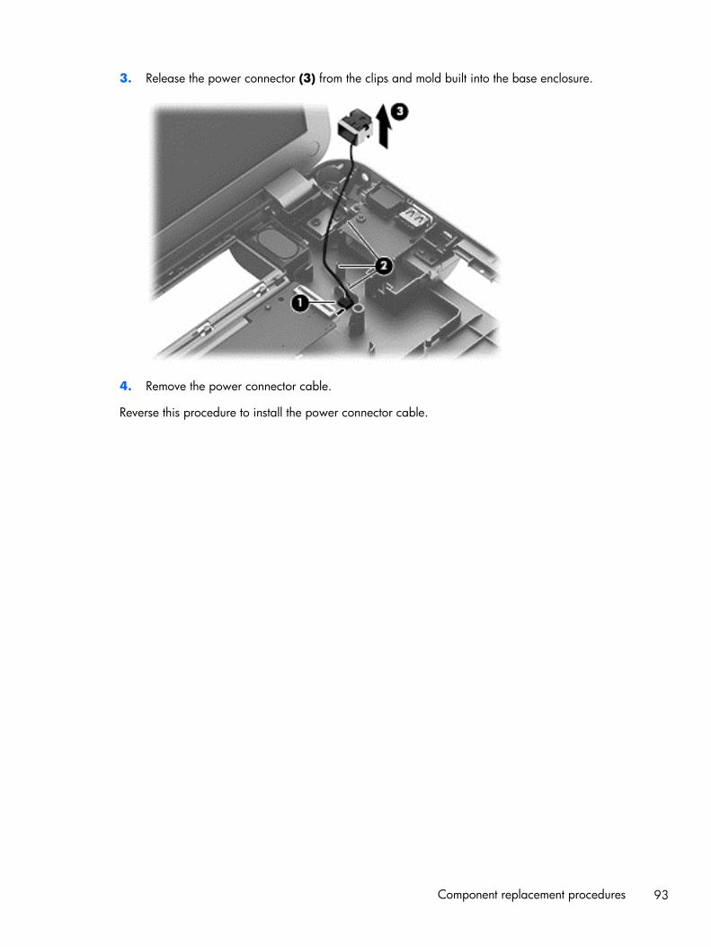
3. Release the power connector (3) from the clips and mold built into the base enclosure.
4. Remove the power connector cable.
Reverse this procedure to install the power connector cable.
Component replacement procedures 93
Speakers
Description Spare part number
Speakers (include left and right speakers and cables) 719865-001
Before removing the speakers, follow these steps:
1. Turn off the computer. If you are unsure whether the computer is off or in Hibernation, turn thecomputer on, and then shut it down through the operating system.
2. Disconnect the power from the computer by unplugging the power cord from the computer.
3. Disconnect all external devices from the computer.
4. Remove the battery (see Battery on page 46), and then remove the following components:
a. Optical drive (see Optical drive on page 47)
b. Hard drive (see Hard drive on page 49)
c. WLAN module (see WLAN module on page 51)
d. Keyboard (see Keyboard on page 56)
e. Top cover (see Top cover on page 60)
f. System board (see System board on page 74)
Remove the speakers:
1. Release the speaker cables from the clips (1) and routing channel built into the base enclosure.
2. Release the clips (2) that secure the speakers to the base enclosure.
94 Chapter 6 Removal and replacement procedures for Authorized Service Provider parts
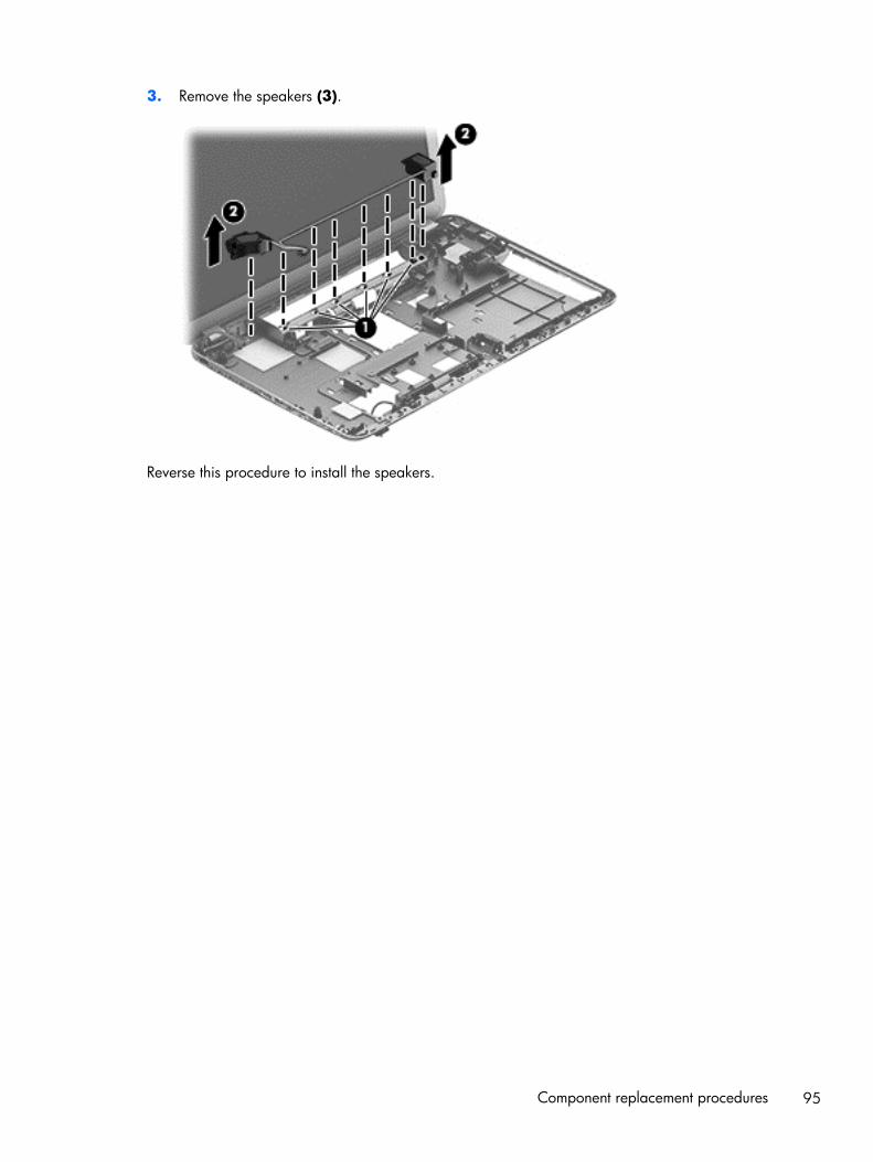
3. Remove the speakers (3).
Reverse this procedure to install the speakers.
Component replacement procedures 95
Optical drive connector cable
Description Spare part number
Optical drive connector cable 719846-001
Before removing the optical drive connector cable, follow these steps:
1. Turn off the computer. If you are unsure whether the computer is off or in Hibernation, turn thecomputer on, and then shut it down through the operating system.
2. Disconnect the power from the computer by unplugging the power cord from the computer.
3. Disconnect all external devices from the computer.
4. Remove the battery (see Battery on page 46), and then remove the following components:
a. Optical drive (see Optical drive on page 47)
b. Hard drive (see Hard drive on page 49)
c. WLAN module (see WLAN module on page 51)
d. Keyboard (see Keyboard on page 56)
e. Top cover (see Top cover on page 60)
f. System board (see System board on page 74)
Remove the optical drive connector cable:
1. Release the optical drive connector cable from the clips (1) and routing channel built into thebase enclosure.
96 Chapter 6 Removal and replacement procedures for Authorized Service Provider parts
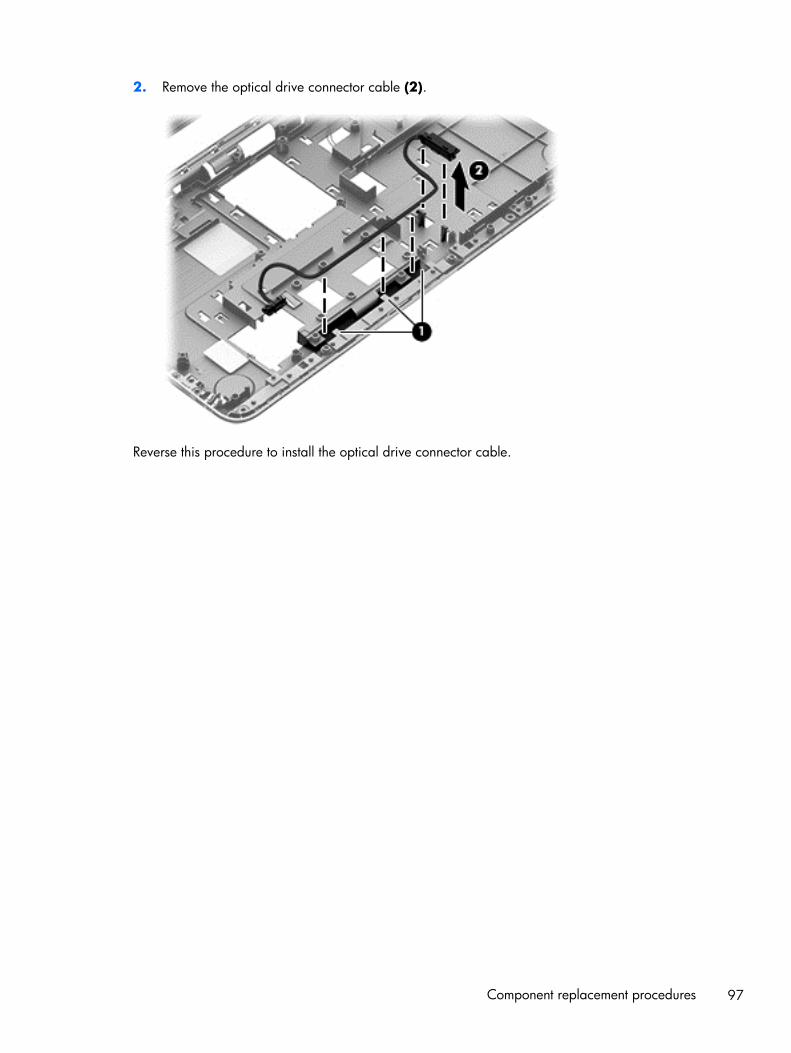
2. Remove the optical drive connector cable (2).
Reverse this procedure to install the optical drive connector cable.
Component replacement procedures 97
7 Using Setup Utility (BIOS) andSystem Diagnostics
Setup Utility, or Basic Input/Output System (BIOS), controls communication between all the input andoutput devices on the system (such as disk drives, display, keyboard, mouse, and printer). Setup Utility(BIOS) includes settings for the types of devices installed, the startup sequence of the computer, and theamount of system and extended memory.
Starting Setup Utility (BIOS)To start Setup Utility (BIOS), turn on or restart the computer, quickly press esc, and then press f10.
Information about how to navigate in Setup Utility (BIOS) is located at the bottom of the screen.
NOTE: Use extreme care when making changes in Setup Utility (BIOS). Errors can prevent thecomputer from operating properly.
Updating the BIOSUpdated versions of the BIOS may be available on the HP website.
Most BIOS updates on the HP website are packaged in compressed files called SoftPaqs.
Some download packages contain a file named Readme.txt, which contains information regardinginstalling and troubleshooting the file.
Determining the BIOS version
To determine whether available BIOS updates contain later BIOS versions than those currently installedon the computer, you need to know the version of the system BIOS currently installed.
BIOS version information (also known as ROM date and System BIOS) can be revealed by pressing fn+esc (if you are already in Windows) or by using Setup Utility (BIOS).
1. Start Setup Utility (BIOS).
2. Use the arrow keys to select Main and make note of your current BIOS version.
98 Chapter 7 Using Setup Utility (BIOS) and System Diagnostics
3. To exit Setup Utility (BIOS) without saving your changes, use the arrow keys to select Exit, selectExit Discarding Changes, and then press enter.
4. Select Yes.
Downloading a BIOS update
CAUTION: To reduce the risk of damage to the computer or an unsuccessful installation, downloadand install a BIOS update only when the computer is connected to reliable external power using the ACadapter. Do not download or install a BIOS update while the computer is running on battery power,docked in an optional docking device, or connected to an optional power source. During thedownload and installation, follow these instructions:
Do not disconnect power from the computer by unplugging the power cord from the AC outlet.
Do not shut down the computer or initiate Sleep.
Do not insert, remove, connect, or disconnect any device, cable, or cord.
1. From the Start screen, type support, and then select the HP Support Assistant app.
2. Click Updates and tune-ups, and then click Check for HP updates now.
3. Follow the on-screen instructions.
4. At the download area, follow these steps:
a. Identify the most recent BIOS update and compare it to the BIOS version currently installed onyour computer. If the update is more recent than your BIOS, make a note of the date, name,or other identifier. You may need this information to locate the update later, after it has beendownloaded to your hard drive.
b. Follow the on-screen instructions to download your selection to the hard drive.
If the update is more recent than your BIOS, make a note of the path to the location on yourhard drive where the BIOS update is downloaded. You will need to access this path whenyou are ready to install the update.
NOTE: If you connect your computer to a network, consult the network administrator beforeinstalling any software updates, especially system BIOS updates.
BIOS installation procedures vary. Follow any instructions that are revealed on the screen after thedownload is complete. If no instructions are revealed, follow these steps:
1. From the Start screen, type e, and then select File Explorer.
2. Click your hard drive designation. The hard drive designation is typically Local Disk (C:).
3. Using the hard drive path you recorded earlier, open the folder on your hard drive that containsthe update.
4. Double-click the file that has an .exe extension (for example, filename.exe).
The BIOS installation begins.
5. Complete the installation by following the on-screen instructions.
Updating the BIOS 99
NOTE: After a message on the screen reports a successful installation, you can delete thedownloaded file from your hard drive.
Using System DiagnosticsSystem Diagnostics allows you to run diagnostic tests to determine if the computer hardware isfunctioning properly.
To start System Diagnostics:
1. Turn on or restart the computer, quickly press esc, and then press f2.
2. Click the diagnostic test you want to run, and then follow the on-screen instructions.
NOTE: If you need to stop a diagnostic test while it is running, press esc.
100 Chapter 7 Using Setup Utility (BIOS) and System Diagnostics
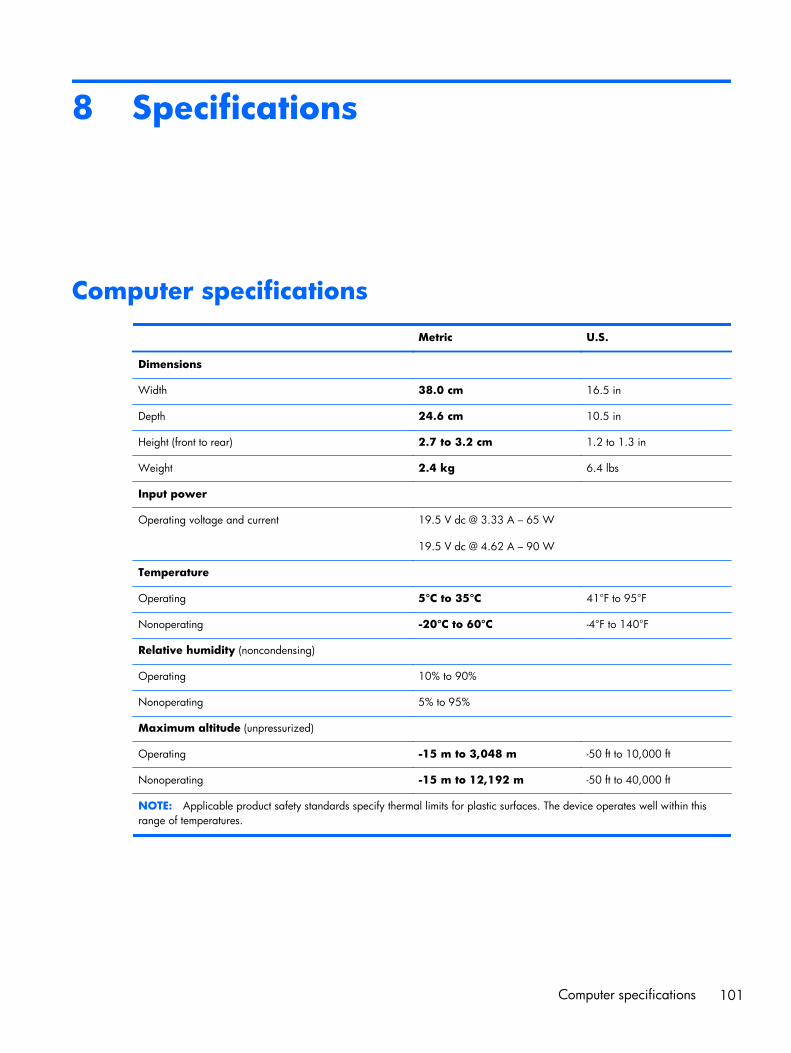
8 Specifications
Computer specifications
Metric U.S.
Dimensions
Width 38.0 cm 16.5 in
Depth 24.6 cm 10.5 in
Height (front to rear) 2.7 to 3.2 cm 1.2 to 1.3 in
Weight 2.4 kg 6.4 lbs
Input power
Operating voltage and current 19.5 V dc @ 3.33 A – 65 W
19.5 V dc @ 4.62 A – 90 W
Temperature
Operating 5°C to 35°C 41°F to 95°F
Nonoperating -20°C to 60°C -4°F to 140°F
Relative humidity (noncondensing)
Operating 10% to 90%
Nonoperating 5% to 95%
Maximum altitude (unpressurized)
Operating -15 m to 3,048 m -50 ft to 10,000 ft
Nonoperating -15 m to 12,192 m -50 ft to 40,000 ft
NOTE: Applicable product safety standards specify thermal limits for plastic surfaces. The device operates well within thisrange of temperatures.
Computer specifications 101
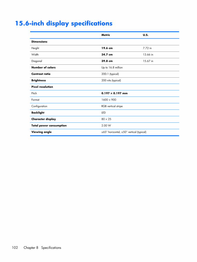
15.6-inch display specifications
Metric U.S.
Dimensions
Height 19.6 cm 7.72 in
Width 34.7 cm 13.66 in
Diagonal 39.8 cm 15.67 in
Number of colors Up to 16.8 million
Contrast ratio 200:1 (typical)
Brightness 200 nits (typical)
Pixel resolution
Pitch 0.197 × 0.197 mm
Format 1600 × 900
Configuration RGB vertical stripe
Backlight LED
Character display 80 × 25
Total power consumption 2.00 W
Viewing angle ±65° horizontal, ±50° vertical (typical)
102 Chapter 8 Specifications
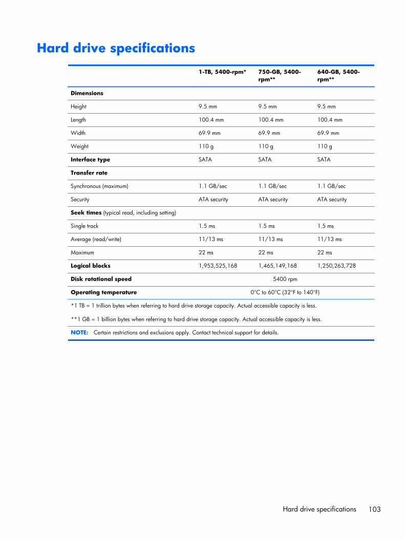
Hard drive specifications
1-TB, 5400-rpm* 750-GB, 5400-rpm**
640-GB, 5400-rpm**
Dimensions
Height 9.5 mm 9.5 mm 9.5 mm
Length 100.4 mm 100.4 mm 100.4 mm
Width 69.9 mm 69.9 mm 69.9 mm
Weight 110 g 110 g 110 g
Interface type SATA SATA SATA
Transfer rate
Synchronous (maximum) 1.1 GB/sec 1.1 GB/sec 1.1 GB/sec
Security ATA security ATA security ATA security
Seek times (typical read, including setting)
Single track 1.5 ms 1.5 ms 1.5 ms
Average (read/write) 11/13 ms 11/13 ms 11/13 ms
Maximum 22 ms 22 ms 22 ms
Logical blocks 1,953,525,168 1,465,149,168 1,250,263,728
Disk rotational speed 5400 rpm
Operating temperature 0°C to 60°C (32°F to 140°F)
*1 TB = 1 trillion bytes when referring to hard drive storage capacity. Actual accessible capacity is less.
**1 GB = 1 billion bytes when referring to hard drive storage capacity. Actual accessible capacity is less.
NOTE: Certain restrictions and exclusions apply. Contact technical support for details.
Hard drive specifications 103
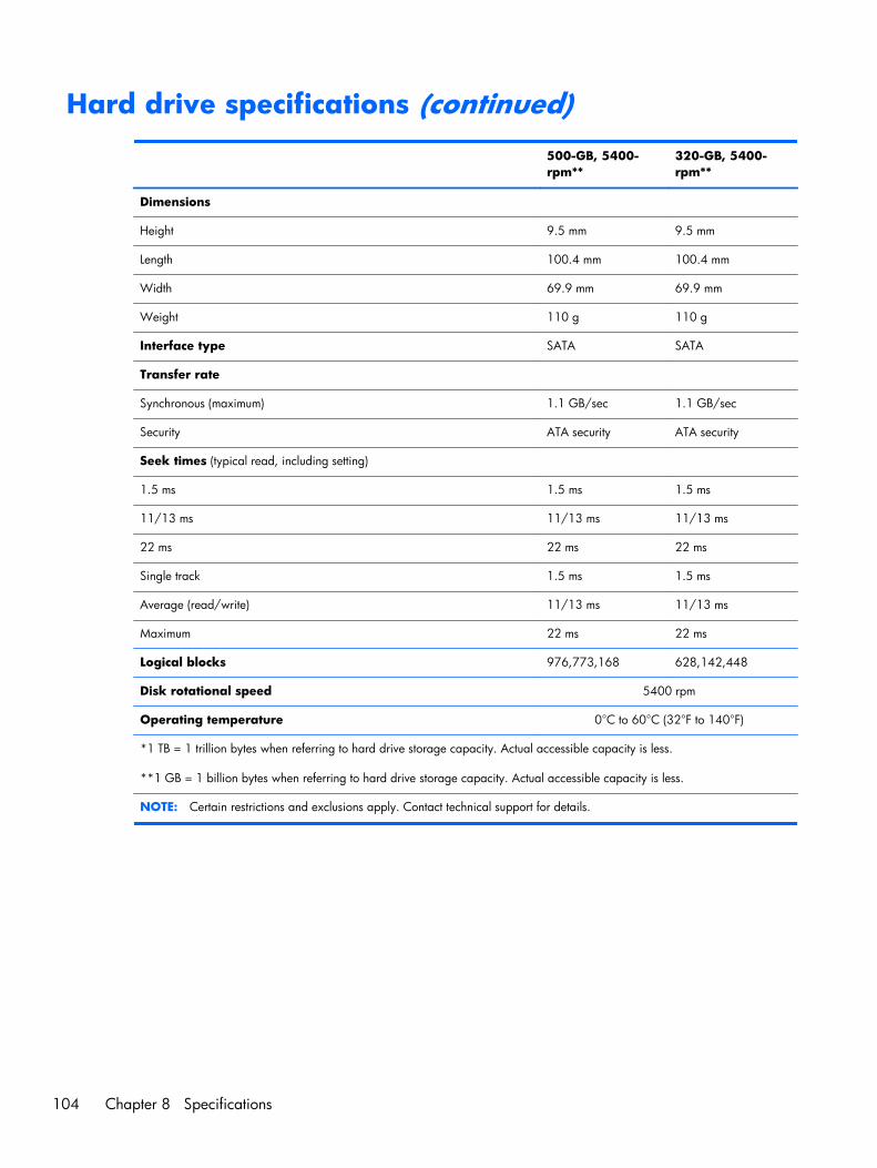
Hard drive specifications (continued) 500-GB, 5400-
rpm**320-GB, 5400-rpm**
Dimensions
Height 9.5 mm 9.5 mm
Length 100.4 mm 100.4 mm
Width 69.9 mm 69.9 mm
Weight 110 g 110 g
Interface type SATA SATA
Transfer rate
Synchronous (maximum) 1.1 GB/sec 1.1 GB/sec
Security ATA security ATA security
Seek times (typical read, including setting)
1.5 ms 1.5 ms 1.5 ms
11/13 ms 11/13 ms 11/13 ms
22 ms 22 ms 22 ms
Single track 1.5 ms 1.5 ms
Average (read/write) 11/13 ms 11/13 ms
Maximum 22 ms 22 ms
Logical blocks 976,773,168 628,142,448
Disk rotational speed 5400 rpm
Operating temperature 0°C to 60°C (32°F to 140°F)
*1 TB = 1 trillion bytes when referring to hard drive storage capacity. Actual accessible capacity is less.
**1 GB = 1 billion bytes when referring to hard drive storage capacity. Actual accessible capacity is less.
NOTE: Certain restrictions and exclusions apply. Contact technical support for details.
104 Chapter 8 Specifications
9 Backing up, restoring, andrecovering
Your computer includes tools provided by HP and the operating system to help you safeguard yourinformation and retrieve it if you ever need to. These tools will help you return your computer to aproper working state or even back to the original factory state, all with simple steps.
This chapter provides information about the following processes:
● Creating recovery media and backups
● Restoring and recovering your system
NOTE: This guide describes an overview of backing up, restoring and recovering options. For moredetails about the tools provided, see Help and Support. From the Start screen, type h, and then selectHelp and Support.
105
Creating recovery media and backupsRecovery after a system failure is only as good as your most recent backup.
1. After you successfully set up the computer, create HP Recovery media. This step creates a backupof the HP Recovery partition on the computer. The backup can be used to reinstall the originaloperating system in cases where the hard drive is corrupted or has been replaced.
HP Recovery media you create will provide the following recovery options:
● System Recovery—Reinstalls the original operating system and the programs that wereinstalled at the factory.
● Minimized Image Recovery—Reinstalls the operating system and all hardware-related driversand software, but not other software applications.
● Factory Reset—Restores the computer to its original factory state by deleting all informationfrom the hard drive and re-creating the partitions. Then it reinstalls the operating system andthe software that was installed at the factory.
2. As you add hardware and software programs, create system restore points. A system restore pointis a snapshot of certain hard drive contents saved by Windows System Restore at a specific time.A system restore point contains information that Windows uses, such as registry settings. Windowscreates a system restore point for you automatically during a Windows update and during othersystem maintenance (such as a software update, security scanning, or system diagnostics). Youcan also manually create a system restore point at any time. For more information and steps forcreating specific system restore points, see Help and Support. From the Start screen, type h, andthen select Help and Support.
3. As you add photos, video, music, and other personal files, create a backup of your personalinformation. Windows File History can be set to regularly and automatically back up files fromlibraries, desktop, contacts, and favorites. If files are accidentally deleted from the hard drive andthey can no longer be restored from the Recycle Bin, or if files become corrupted, you can restorethe files that you backed up using File History. Restoring files is also useful if you ever choose toreset the computer by reinstalling Windows or choose to recover using HP Recovery Manager.
NOTE: File History is not enabled by default, so you must turn it on.
For more information and steps for enabling Windows File History, see Help and Support. Fromthe Start screen, type h, and then select Help and Support.
106 Chapter 9 Backing up, restoring, and recovering
Creating HP Recovery media
HP Recovery Manager is a software program that offers a way to create recovery media after yousuccessfully set up the computer. HP Recovery media can be used to perform system recovery if thehard drive becomes corrupted. System recovery reinstalls the original operating system and thesoftware programs installed at the factory, and then configures the settings for the programs. HPRecovery media can also be used to customize the system or aid in the replacement of a hard drive.
● Only one set of HP Recovery media can be created. Handle these recovery tools carefully, andkeep them in a safe place.
● HP Recovery Manager examines the computer and determines the required storage capacity forthe blank USB flash drive or the number of blank DVD discs that will be required.
● To create recovery discs, your computer must have an optical drive with DVD writer capability,and you must use only high-quality blank DVD-R, DVD+R, DVD-R DL, or DVD+R DL discs. Do notuse rewritable discs such as CD±RW, DVD±RW, double-layer DVD±RW, or BD-RE (rewritable Blu-ray) discs; they are not compatible with HP Recovery Manager software. Or instead you can use ahigh-quality blank USB flash drive.
● If your computer does not include an integrated optical drive with DVD writer capability, but youwould like to create DVD recovery media, you can use an external optical drive (purchasedseparately) to create recovery discs, or you can obtain recovery discs for your computer from theHP website. For U.S. support, go to http://www.hp.com/go/contactHP. For worldwide support,go to http://welcome.hp.com/country/us/en/wwcontact_us.html. If you use an external opticaldrive, it must be connected directly to a USB port on the computer; the drive cannot be connectedto a USB port on an external device, such as a USB hub.
● Be sure that the computer is connected to AC power before you begin creating therecovery media.
● The creation process can take up to an hour or more. Do not interrupt the creation process.
● If necessary, you can exit the program before you have finished creating all of the recovery DVDs.HP Recovery Manager will finish burning the current DVD. The next time you start HP RecoveryManager, you will be prompted to continue, and the remaining discs will be burned.
To create HP Recovery media:
1. From the Start screen, type recovery, and then select HP Recovery Manager.
2. Select Recovery Media Creation, and then follow the on-screen instructions.
If you ever need to recover the system, see Recovering using HP Recovery Manager on page 110.
Creating recovery media and backups 107
Restore and recoveryThere are several options for recovering your system. Choose the method that best matches yoursituation and level of expertise:
● If you need to restore your personal files and data, you can use Windows File History to restoreyour information from the backups you created. For more information and steps for using FileHistory, see Help and Support. From the Start screen, type h, and then select Help andSupport.
● If you need to correct a problem with a preinstalled application or driver, use the Drivers andApplications Reinstall option of HP Recovery Manager to reinstall the individual applicationor driver.
From the Start screen, type recovery, select HP Recovery Manager, select Drivers andApplications Reinstall, and then follow the on-screen instructions.
● If you want to restore the system to a previous state without losing any personal information,Windows System Restore is an option. System Restore allows you to restore without therequirements of Windows Refresh or a reinstallation. Windows creates system restore pointsautomatically during a Windows update and other system maintenance events. Even if you did notmanually create a restore point, you can choose to restore to a previous point, automaticallycreated. For more information and steps for using Windows System Restore, see Help andSupport. From the Start screen, type h, and then select Help and Support.
● If you want a quick and easy way to recover the system without losing your personal information,settings, or apps that came preinstalled on your computer or were purchased from the WindowsStore, consider using Windows Refresh. This option does not require backing up data to anotherdrive. See Using Windows Refresh for quick and easy recovery on page 109.
● If you want to reset your computer to its original state, Windows provides an easy way to removeall personal data, apps, and settings, and reinstall Windows.
For more information, see Remove everything and reinstall Windows on page 109.
● If you want to reset your computer using a minimized image, you can choose the HP MinimizedImage Recovery option from the HP Recovery partition (select models only) or HP Recovery media.Minimized Image Recovery installs only drivers and hardware-enabling applications. Otherapplications included in the image continue to be available for installation through the Drivers andApplications Reinstall option in HP Recovery Manager.
For more information, see Recovering using HP Recovery Manager on page 110.
● If you want to recover the computer's original factory partitioning and content, you can choose theSystem Recovery option from the HP Recovery media. For more information, see Recovering usingHP Recovery Manager on page 110.
● If you have replaced the hard drive, you can use the Factory Reset option of HP Recovery media torestore the factory image to the replacement drive. For more information, see Recovering using HPRecovery Manager on page 110.
● If you wish to remove the recovery partition to reclaim hard drive space, HP Recovery Manageroffers the Remove Recovery Partition option.
108 Chapter 9 Backing up, restoring, and recovering
For more information, see Removing the HP Recovery partition on page 112.
Using Windows Refresh for quick and easy recovery
When your computer is not working properly and you need to regain system stability, the WindowsRefresh option allows you to start fresh and keep what is important to you.
IMPORTANT: Refresh removes any traditional applications that were not originally installed on thesystem at the factory.
NOTE: During Refresh, a list of removed traditional applications will be saved so that you have aquick way to see what you might need to reinstall. See Help and Support for instructions on reinstallingtraditional applications. From the Start screen, type h, and then select Help and Support.
NOTE: You may be prompted for your permission or password when using Refresh. See Help andSupport for more information. From the Start screen, type h, and then select Help and Support.
To start Refresh:
1. From the Start screen, point to the upper-right or lower-right corner of the screen to revealthe charms.
2. Click Settings.
3. Click Change PC settings in the bottom-right corner of the screen, and then select Generalfrom the PC settings screen.
4. Scroll the right-side choices down to display Refresh your PC without affecting your files.
5. Under Refresh your PC without affecting your files, select Get started, and then followthe on-screen instructions.
Remove everything and reinstall Windows
Sometimes you want to perform detailed reformatting of your computer, or you want to removepersonal information before you give away or recycle your computer. The process described in thissection provides a speedy, simple way to return the computer to its original state. This option removesall personal data, apps, and settings from your computer, and reinstalls Windows.
IMPORTANT: This option does not provide backups of your information. Before using this option,back up any personal information you wish to retain.
You can initiate this option by using the f11 key or from the Start screen.
To use the f11 key:
1. Press f11 while the computer boots.
– or –
Press and hold f11 as you press the power button.
2. Choose your keyboard layout.
Restore and recovery 109
3. Select Troubleshoot from the boot options menu.
4. Select Reset your PC, and then follow the on-screen instructions.
To use the Start screen:
1. From the Start screen, point to the upper-right or lower-right corner of the screen to revealthe charms.
2. Click Settings.
3. Click Change PC settings in the bottom-right corner of the screen, and then select Generalfrom the PC settings screen.
4. Scroll the right-side choices down to display Remove everything and reinstall Windows.
5. Under Remove everything and reinstall Windows, select Get started, and follow theon-screen instructions.
Recovering using HP Recovery Manager
HP Recovery Manager software allows you to recover the computer to its original factory state. Usingthe HP Recovery media you created, you can choose from one of the following recovery options:
● System Recovery—Reinstalls the original operating system, and then configures the settings for theprograms that were installed at the factory.
● Minimized Image Recovery—Reinstalls the operating system and all hardware-related drivers andsoftware, but not other software applications.
● Factory Reset—Restores the computer to its original factory state by deleting all information fromthe hard drive and re-creating the partitions. Then it reinstalls the operating system and thesoftware that was installed at the factory.
The HP Recovery partition (select models only) allows Minimized Image Recovery.
What you need to know
● HP Recovery Manager recovers only software that was installed at the factory. For software notprovided with this computer, you must either download the software from the manufacturer'swebsite or reinstall the software from the media provided by the manufacturer.
● Recovery through HP Recovery Manager should be used as a final attempt to correctcomputer issues.
● HP Recovery media must be used if the computer hard drive fails.
● To use the Factory Reset or System Recovery options, you must use HP Recovery media.
● If the HP Recovery media do not work, you can obtain recovery media for your system from the HPwebsite. For U.S. support, go to http://www.hp.com/go/contactHP. For worldwide support, goto http://welcome.hp.com/country/us/en/wwcontact_us.html.
IMPORTANT: HP Recovery Manager does not automatically provide backups of your personal data.Before beginning recovery, back up any personal data you wish to retain.
110 Chapter 9 Backing up, restoring, and recovering
Using the HP Recovery partition to recover a minimized image(select models only)
The HP Recovery partition (select models only) allows you to perform a minimized image recoverywithout the need for recovery discs or a recovery USB flash drive. This type of recovery can only beused if the hard drive is still working.
To start HP Recovery Manager from the HP Recovery partition:
1. Press f11 while the computer boots.
– or –
Press and hold f11 as you press the power button.
2. Choose your keyboard layout.
3. Select Troubleshoot from the boot options menu.
4. Select HP Recovery Manager, and follow the on-screen instructions.
Using HP Recovery media to recover
You can use HP Recovery media to recover the original system. This method can be used if your systemdoes not have an HP Recovery partition or if the hard drive is not working properly.
1. If possible, back up all personal files.
2. Insert the first HP Recovery disc you created into the optical drive on your computer or into anoptional external optical drive, and then restart the computer.
– or –
Insert the HP Recovery USB flash drive you created into a USB port on your computer, and thenrestart the computer.
NOTE: If the computer does not automatically restart in HP Recovery Manager, change thecomputer boot order. See Changing the computer boot order on page 111.
3. Follow the on-screen instructions.
Changing the computer boot order
If computer does not restart in HP Recovery Manager, you can change the computer boot order, whichis the order of devices listed in BIOS where the computer looks for startup information. You can changethe selection for an optical drive or a USB flash drive.
To change the boot order:
1. Insert the HP Recovery media you created.
2. Restart the computer, quickly press esc, and then press f9 for boot options.
Restore and recovery 111
3. Select the optical drive or USB flash drive you want to boot from.
4. Follow the on-screen instructions.
Removing the HP Recovery partition
HP Recovery Manager software allows you to remove the HP Recovery partition to free up harddrive space.
IMPORTANT: Removing the HP Recovery partition means you can no longer use Windows Refresh,the Windows Remove everything and reinstall Windows option, or the HP Recovery Manager optionfor minimized image recovery. Create HP Recovery media before removing the Recovery partition toensure you have recovery options; see Creating HP Recovery media on page 107.
Follow these steps to remove the HP Recovery partition:
1. From the Start screen, type recovery, and then select HP Recovery Manager.
2. Select Remove Recovery Partition, and then follow the on-screen instructions.
112 Chapter 9 Backing up, restoring, and recovering
10 Power cord set requirements
The wide-range input feature of the computer permits it to operate from any line voltage from 100 to120 volts AC, or from 220 to 240 volts AC.
The 3-conductor power cord set included with the computer meets the requirements for use in thecountry or region where the equipment is purchased.
Power cord sets for use in other countries and regions must meet the requirements of the country orregion where the computer is used.
Requirements for all countriesThe following requirements are applicable to all countries and regions:
● The length of the power cord set must be at least 1.0 m (3.3 ft) and no more than 2.0 m (6.5 ft).
● All power cord sets must be approved by an acceptable accredited agency responsible forevaluation in the country or region where the power cord set will be used.
● The power cord sets must have a minimum current capacity of 10 amps and a nominal voltagerating of 125 or 250 V AC, as required by the power system of each country or region.
● The appliance coupler must meet the mechanical configuration of an EN 60 320/IEC 320Standard Sheet C13 connector for mating with the appliance inlet on the back of the computer.
Requirements for all countries 113
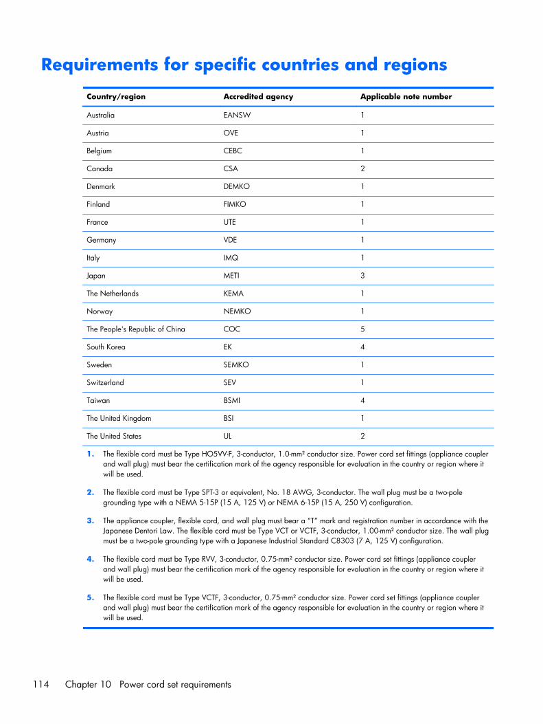
Requirements for specific countries and regions
Country/region Accredited agency Applicable note number
Australia EANSW 1
Austria OVE 1
Belgium CEBC 1
Canada CSA 2
Denmark DEMKO 1
Finland FIMKO 1
France UTE 1
Germany VDE 1
Italy IMQ 1
Japan METI 3
The Netherlands KEMA 1
Norway NEMKO 1
The People's Republic of China COC 5
South Korea EK 4
Sweden SEMKO 1
Switzerland SEV 1
Taiwan BSMI 4
The United Kingdom BSI 1
The United States UL 2
1. The flexible cord must be Type HO5VV-F, 3-conductor, 1.0-mm² conductor size. Power cord set fittings (appliance couplerand wall plug) must bear the certification mark of the agency responsible for evaluation in the country or region where itwill be used.
2. The flexible cord must be Type SPT-3 or equivalent, No. 18 AWG, 3-conductor. The wall plug must be a two-polegrounding type with a NEMA 5-15P (15 A, 125 V) or NEMA 6-15P (15 A, 250 V) configuration.
3. The appliance coupler, flexible cord, and wall plug must bear a “T” mark and registration number in accordance with theJapanese Dentori Law. The flexible cord must be Type VCT or VCTF, 3-conductor, 1.00-mm² conductor size. The wall plugmust be a two-pole grounding type with a Japanese Industrial Standard C8303 (7 A, 125 V) configuration.
4. The flexible cord must be Type RVV, 3-conductor, 0.75-mm² conductor size. Power cord set fittings (appliance couplerand wall plug) must bear the certification mark of the agency responsible for evaluation in the country or region where itwill be used.
5. The flexible cord must be Type VCTF, 3-conductor, 0.75-mm² conductor size. Power cord set fittings (appliance couplerand wall plug) must bear the certification mark of the agency responsible for evaluation in the country or region where itwill be used.
114 Chapter 10 Power cord set requirements

11 Recycling
When a non-rechargeable or rechargeable battery has reached the end of its useful life, do not disposeof the battery in general household waste. Follow the local laws and regulations in your area forbattery disposal.
HP encourages customers to recycle used electronic hardware, HP original print cartridges, andrechargeable batteries. For more information about recycling programs, see the HP Web site athttp://www.hp.com/recycle.
115
Index
AAC adapter light 16AC adapter, spare part numbers
30, 32, 34action keys 11antenna
locations 9removal 73spare part number 28, 35, 74
Antenna Kit, spare part number28
audio, product description 5audio-in jack 14audio-out jack 14
Bbase enclosure, spare part
number 26, 36battery
removal 46spare part number 46spare part numbers 26, 32
battery bay 17battery release latch 17bottom components 17button components 10buttons
optical drive eject 16power 10TouchPad 13
Ccables, service considerations 41caps lock light 12chipset, product description 2components
bottom 17buttons 10display 9
keys 11left-side 14lights 12right-side 16speakers 10TouchPad 13
computermajor components 20specifications 101
connectors, serviceconsiderations 41
Ddisplay
components 9specifications 102
display assembly, removal 66display bezel
removal 68spare part number 28, 34, 69
display enclosure, spare partnumbers 28, 34
display panelproduct description 4removal 71spare part number 28, 36, 72
display panel cableremoval 73spare part number 28, 35, 73
drives, preventing damage 41DVD+/-RW Double Layer
SuperMulti Driveremoval 47spare part number 47
DVD±RW Double Layer SuperMultiDrive
spare part number 26, 30, 36
DVD±RW Double-Layer withSuperMulti Drive
precautions 41
Eelectrostatic discharge 42equipment guidelines 44esc key 11Ethernet, product description 5external monitor port, location 14
Ffan
removal 79spare part number 25, 35, 79
fn key 11
Ggraphics, product description 3grounding guidelines 42guidelines
equipment 44grounding 42packaging 43transporting 43workstation 43
Hhard drive
precautions 41product description 5removal 49spare part numbers 26, 29,
31, 32, 49specifications 103
hard drive bracketillustrated 30removal 50
116 Index
hard drive connector cableillustrated 30removal 50
Hard Drive Hardware Kitcontents 29spare part number 26, 29, 34
hard drive light 15HDMI port 14headphone jack 14heat sink
removal 80spare part number 80spare part numbers 25, 36,
38hinge
removal 72spare part number 28, 35, 72
Iintegrated numeric keypad 11
Jjacks
audio-in 14audio-out 14headphone 14microphone 14network 16RJ-45 (network) 16
Kkey components 11keyboard
product description 6removal 56spare part numbers 21, 34,
35, 36, 37, 56keys
action 11esc 11fn 11integrated numeric keypad 11num lk 11Windows key 11
Lleft-side components 14light components 12lights
AC adapter 16caps lock 12
hard drive 15mute 12power 12, 15webcam 9wireless 12
Mmass storage device
illustrated 29precautions 41spare part numbers 29
Media Card Reader 14memory module
product description 4removal 53spare part numbers 26, 32,
53microphone
location 9product description 5
microphone jack 14model name 1monitor port 14mute light 12
Nnetwork jack 16num lk key 11
Ooperating system, product
description 7optical drive
location 16precautions 41product description 5removal 47spare part number 26, 30,
36, 47optical drive connector cable
removal 96spare part number 26, 34, 96
optical drive eject button 16
Ppackaging guidelines 43PCH heat sink
removal 87spare part number 25, 36, 87
plastic parts, serviceconsiderations 40
pointing device, productdescription 6
portsexternal monitor 14HDMI 14monitor 14product description 6USB 2.0 16USB 3.0 14
power button 10power button board
removal 64spare part number 23, 34, 64
power connector 16power connector cable
removal 92spare part number 26, 35spare part numbers 92
power cordset requirements 113spare part numbers 30, 31
power light 12, 15power requirements, product
description 7processor
removal 85spare part numbers 25, 32,
33, 34, 38, 85processor, product description 1product description
audio 5chipset 2display panel 4Ethernet 5external media cards 6graphics 3hard drive 5keyboard 6memory module 4microphone 5operating system 7optical drive 5pointing device 6ports 6power requirements 7processors 1product name 1security 7serviceability 7
Index 117
video 5wireless 5
product name 1
Rremoval/replacement
procedures 45, 55right-side components 16RJ-45 (network) jack 16RJ-45/USB board
removal 91spare part number 26, 34, 91
RTC batteryremoval 89spare part number 26, 31spare part numbers 89
Rubber Kit, spare part number26, 35
SScrew Kit, spare part number 30,
35security cable slot, location 16security, product description 7service considerations
cables 41connectors 41plastic parts 40
service coverlocation 17removal 47spare part number 27, 36, 47
service tag 18serviceability, product description
7speaker components 10Speaker Kit, spare part number
26, 36speakers
location 10removal 94spare part number 26, 36, 94
specificationscomputer 101display 102hard drive 103
system boardremoval 74spare part numbers 23, 33,
36, 38, 39, 74
TThermal Material Kit, spare part
number 25, 36tools required 40top cover
removal 60spare part numbers 22, 36,
60TouchPad button 13TouchPad button board
removal 65spare part number 23, 36, 65
TouchPad components 13TouchPad zone 13transporting guidelines 43
UUSB 2.0 port 16USB 3.0 port 14
Vvent 14, 17video, product description 5
Wwebcam 9webcam light 9webcam/microphone module
removal 69spare part number 28, 34, 70
Windows key 11wireless antenna
locations 9removal 73spare part number 28, 35, 74
Wireless Antenna Kit, spare partnumber 35
wireless light 12wireless, product description 5WLAN module
removal 51spare part numbers 26, 32,
51workstation guidelines 43
118 Index