Embed Size (px)
Citation preview
HP ENVY m6 Notebook PCHP ENVY Notebook PC
Maintenance and Service Guide
© Copyright 2014 Hewlett-PackardDevelopment Company, L.P.
Bluetooth is a trademark owned by itsproprietor and used by Hewlett-PackardCompany under license. Intel and Core are U.S.registered trademarks of Intel Corporation.Microsoft and Windows are U.S. registeredtrademarks of Microsoft Corporation. SD Logois a trademark of its proprietor.
The information contained herein is subject tochange without notice. The only warranties forHP products and services are set forth in theexpress warranty statements accompanyingsuch products and services. Nothing hereinshould be construed as constituting anadditional warranty. HP shall not be liable fortechnical or editorial errors or omissionscontained herein.
First Edition: November 2014
Document Part Number: 803038-001
Product notice
This guide describes features that are commonto most models. Some features may not beavailable on your computer.
Not all features are available in all editions ofWindows 8. This computer may requireupgraded and/or separately purchasedhardware, drivers, and/or software to take fulladvantage of Windows 8 functionality. See forhttp://www.microsoft.com details.
Software terms
By installing, copying, downloading, orotherwise using any software productpreinstalled on this computer, you agree to bebound by the terms of the HP End User LicenseAgreement (EULA). If you do not accept theselicense terms, your sole remedy is to return theentire unused product (hardware andsoftware) within 14 days for a refund subjectto the refund policy of your place of purchase.
For any further information or to request a fullrefund of the computer, please contact yourlocal point of sale (the seller).

Safety warning notice
WARNING! To reduce the possibility of heat-related injuries or of overheating the device, do not place thedevice directly on your lap or obstruct the device air vents. Use the device only on a hard, flat surface. Do notallow another hard surface, such as an adjoining optional printer, or a soft surface, such as pillows or rugs orclothing, to block airflow. Also, do not allow the AC adapter to contact the skin or a soft surface, such aspillows or rugs or clothing, during operation. The device and the AC adapter comply with the user-accessiblesurface temperature limits defined by the International Standard for Safety of Information TechnologyEquipment (IEC 60950).
iii

iv Safety warning notice
Table of contents
1 Product description ....................................................................................................................................... 1
2 External component identification ................................................................................................................. 5
Finding your hardware and software information ................................................................................................ 5
Locating hardware ............................................................................................................................... 5
Locating software ............................................................................................................................... 5
Display ................................................................................................................................................................... 6
Top ......................................................................................................................................................................... 7
TouchPad ............................................................................................................................................. 7
Lights ................................................................................................................................................... 8
Buttons, speakers, and fingerprint reader (select models only) ....................................................... 9
Keys ................................................................................................................................................... 10
Using the action keys ........................................................................................................................ 10
Left side ............................................................................................................................................................... 12
Right side ............................................................................................................................................................. 13
Bottom ................................................................................................................................................................. 14
Service tag ........................................................................................................................................................... 15
3 Illustrated parts catalog .............................................................................................................................. 16
Computer major components ............................................................................................................................. 16
Miscellaneous parts ............................................................................................................................................. 20
Display assembly subcomponents ..................................................................................................................... 21
Mass storage devices .......................................................................................................................................... 22
Sequential part number listing ........................................................................................................................... 23
4 Removal and replacement procedures preliminary requirements .................................................................... 28
Tools required ...................................................................................................................................................... 28
Service considerations ........................................................................................................................................ 28
Plastic parts ....................................................................................................................................... 28
Cables and connectors ...................................................................................................................... 29
Drive handling ................................................................................................................................... 29
Grounding guidelines ........................................................................................................................................... 29
Electrostatic discharge damage ....................................................................................................... 29
Packaging and transporting guidelines ......................................................................... 31
Workstation guidelines ................................................................................ 31
v
5 Removal and replacement procedures for Customer Self-Repair parts ............................................................. 33
Component replacement procedures ................................................................................................................. 33
Battery ............................................................................................................................................... 34
WLAN module .................................................................................................................................... 35
Hard drive .......................................................................................................................................... 38
Memory module ................................................................................................................................ 40
6 Removal and replacement procedures for Authorized Service Provider parts ................................................... 43
Component replacement procedures ................................................................................................................. 43
RTC battery ........................................................................................................................................ 43
Base enclosure .................................................................................................................................. 45
Display assembly .............................................................................................................................. 47
Fan ..................................................................................................................................................... 55
System board .................................................................................................................................... 56
Heat sink ............................................................................................................................................ 60
Processor ........................................................................................................................................... 62
Connector board ................................................................................................................................ 64
Power connector cable ...................................................................................................................... 65
Subwoofer ......................................................................................................................................... 66
Speakers ............................................................................................................................................ 68
TouchPad assembly .......................................................................................................................... 70
Power button board .......................................................................................................................... 72
Keyboard ........................................................................................................................................... 73
7 Using Setup Utility (BIOS) ............................................................................................................................. 76
Starting Setup Utility (BIOS) ................................................................................................................................ 76
Updating the BIOS ................................................................................................................................................ 76
Determining the BIOS version ........................................................................................................... 76
Downloading a BIOS update .............................................................................................................. 77
8 Using HP PC Hardware Diagnostics (UEFI) ...................................................................................................... 78
Downloading HP PC Hardware Diagnostics (UEFI) to a USB device .................................................................... 78
9 Specifications ............................................................................................................................................. 80
Computer specifications ...................................................................................................................................... 80
10 Backing up, restoring, and recovering ......................................................................................................... 81
Creating recovery media and backups ................................................................................................................ 81
Creating HP Recovery media (select models only) ........................................................................... 81
Using Windows tools ........................................................................................................................................... 82
vi
Restore and recovery .......................................................................................................................................... 82
Recovering using HP Recovery Manager .......................................................................................... 83
What you need to know before you get started ............................................................ 83
Using the HP Recovery partition (select models only) .................................................. 84
Using HP Recovery media to recover ............................................................................. 84
Changing the computer boot order ................................................................................ 85
Removing the HP Recovery partition (select models only) ........................................... 85
11 Power cord set requirements ...................................................................................................................... 86
Requirements for all countries ........................................................................................................................... 86
Requirements for specific countries and regions ............................................................................................... 86
12 Recycling .................................................................................................................................................. 88
Index ............................................................................................................................................................. 89
vii

viii
1 Product description
Category Description UMAmodels
Discretetouch
models
Discretenon-touch
models
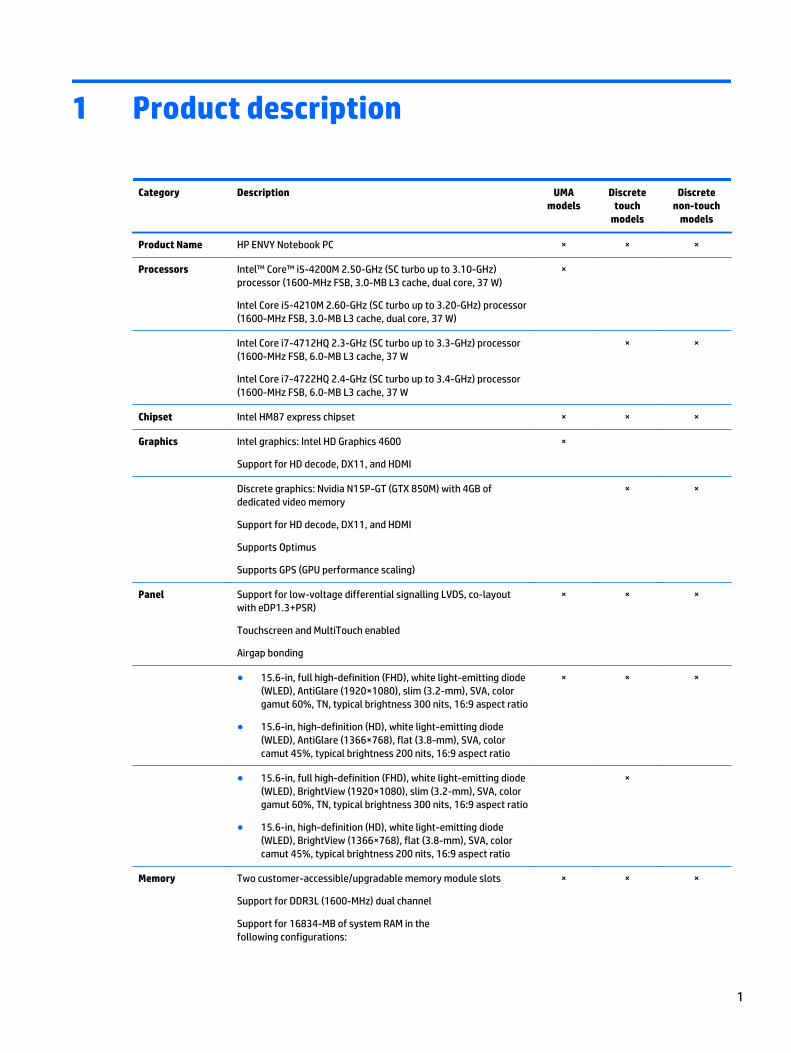
Product Name HP ENVY Notebook PC × × ×
Processors Intel™ Core™ i5-4200M 2.50-GHz (SC turbo up to 3.10-GHz)processor (1600-MHz FSB, 3.0-MB L3 cache, dual core, 37 W)
Intel Core i5-4210M 2.60-GHz (SC turbo up to 3.20-GHz) processor(1600-MHz FSB, 3.0-MB L3 cache, dual core, 37 W)
×
Intel Core i7-4712HQ 2.3-GHz (SC turbo up to 3.3-GHz) processor(1600-MHz FSB, 6.0-MB L3 cache, 37 W
Intel Core i7-4722HQ 2.4-GHz (SC turbo up to 3.4-GHz) processor(1600-MHz FSB, 6.0-MB L3 cache, 37 W
× ×
Chipset Intel HM87 express chipset × × ×
Graphics Intel graphics: Intel HD Graphics 4600
Support for HD decode, DX11, and HDMI
×
Discrete graphics: Nvidia N15P-GT (GTX 850M) with 4GB ofdedicated video memory
Support for HD decode, DX11, and HDMI
Supports Optimus
Supports GPS (GPU performance scaling)
× ×
Panel Support for low-voltage differential signalling LVDS, co-layoutwith eDP1.3+PSR)
Touchscreen and MultiTouch enabled
Airgap bonding
× × ×
● 15.6-in, full high-definition (FHD), white light-emitting diode(WLED), AntiGlare (1920×1080), slim (3.2-mm), SVA, colorgamut 60%, TN, typical brightness 300 nits, 16:9 aspect ratio
● 15.6-in, high-definition (HD), white light-emitting diode(WLED), AntiGlare (1366×768), flat (3.8-mm), SVA, colorcamut 45%, typical brightness 200 nits, 16:9 aspect ratio
× × ×
● 15.6-in, full high-definition (FHD), white light-emitting diode(WLED), BrightView (1920×1080), slim (3.2-mm), SVA, colorgamut 60%, TN, typical brightness 300 nits, 16:9 aspect ratio
● 15.6-in, high-definition (HD), white light-emitting diode(WLED), BrightView (1366×768), flat (3.8-mm), SVA, colorcamut 45%, typical brightness 200 nits, 16:9 aspect ratio
×
Memory Two customer-accessible/upgradable memory module slots
Support for DDR3L (1600-MHz) dual channel
Support for 16834-MB of system RAM in thefollowing configurations:
× × ×
1
Category Description UMAmodels
Discretetouch
models
Discretenon-touch
models
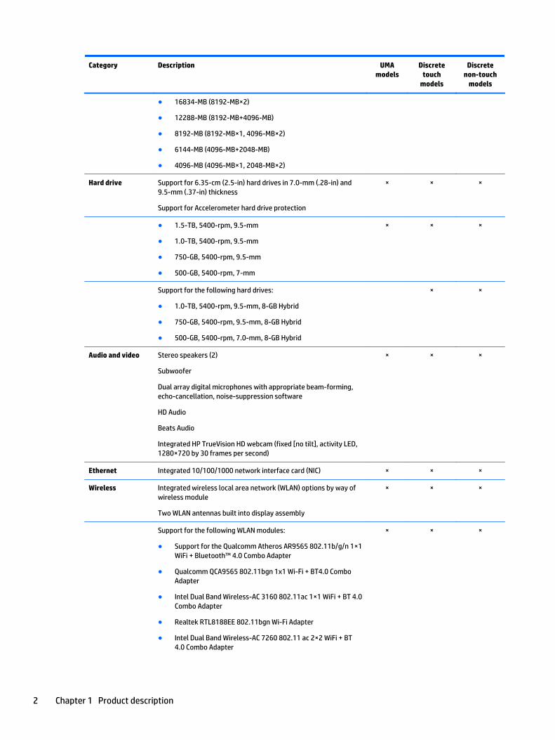
● 16834-MB (8192-MB×2)
● 12288-MB (8192-MB+4096-MB)
● 8192-MB (8192-MB×1, 4096-MB×2)
● 6144-MB (4096-MB+2048-MB)
● 4096-MB (4096-MB×1, 2048-MB×2)
Hard drive Support for 6.35-cm (2.5-in) hard drives in 7.0-mm (.28-in) and9.5-mm (.37-in) thickness
Support for Accelerometer hard drive protection
× × ×
● 1.5-TB, 5400-rpm, 9.5-mm
● 1.0-TB, 5400-rpm, 9.5-mm
● 750-GB, 5400-rpm, 9.5-mm
● 500-GB, 5400-rpm, 7-mm
× × ×
Support for the following hard drives:
● 1.0-TB, 5400-rpm, 9.5-mm, 8-GB Hybrid
● 750-GB, 5400-rpm, 9.5-mm, 8-GB Hybrid
● 500-GB, 5400-rpm, 7.0-mm, 8-GB Hybrid
× ×
Audio and video Stereo speakers (2)
Subwoofer
Dual array digital microphones with appropriate beam-forming,echo-cancellation, noise-suppression software
HD Audio
Beats Audio
Integrated HP TrueVision HD webcam (fixed [no tilt], activity LED,1280×720 by 30 frames per second)
× × ×
Ethernet Integrated 10/100/1000 network interface card (NIC) × × ×
Wireless Integrated wireless local area network (WLAN) options by way ofwireless module
Two WLAN antennas built into display assembly
× × ×
Support for the following WLAN modules:
● Support for the Qualcomm Atheros AR9565 802.11b/g/n 1×1WiFi + Bluetooth™ 4.0 Combo Adapter
● Qualcomm QCA9565 802.11bgn 1x1 Wi-Fi + BT4.0 ComboAdapter
● Intel Dual Band Wireless-AC 3160 802.11ac 1×1 WiFi + BT 4.0Combo Adapter
● Realtek RTL8188EE 802.11bgn Wi-Fi Adapter
● Intel Dual Band Wireless-AC 7260 802.11 ac 2×2 WiFi + BT4.0 Combo Adapter
× × ×
2 Chapter 1 Product description
Category Description UMAmodels
Discretetouch
models
Discretenon-touch
models
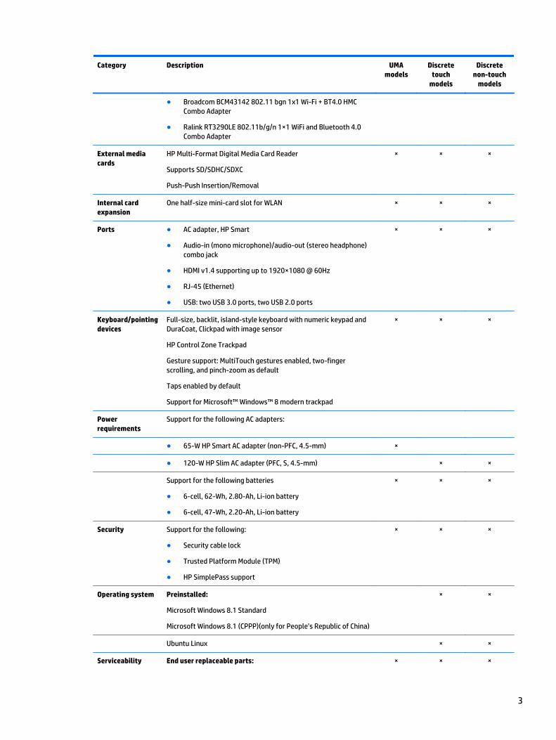
● Broadcom BCM43142 802.11 bgn 1x1 Wi-Fi + BT4.0 HMCCombo Adapter
● Ralink RT3290LE 802.11b/g/n 1×1 WiFi and Bluetooth 4.0Combo Adapter
External mediacards
HP Multi-Format Digital Media Card Reader
Supports SD/SDHC/SDXC
Push-Push Insertion/Removal
× × ×
Internal cardexpansion
One half-size mini-card slot for WLAN × × ×
Ports ● AC adapter, HP Smart
● Audio-in (mono microphone)/audio-out (stereo headphone)combo jack
● HDMI v1.4 supporting up to 1920×1080 @ 60Hz
● RJ-45 (Ethernet)
● USB: two USB 3.0 ports, two USB 2.0 ports
× × ×
Keyboard/pointingdevices
Full-size, backlit, island-style keyboard with numeric keypad andDuraCoat, Clickpad with image sensor
HP Control Zone Trackpad
Gesture support: MultiTouch gestures enabled, two-fingerscrolling, and pinch-zoom as default
Taps enabled by default
Support for Microsoft™ Windows™ 8 modern trackpad
× × ×
Powerrequirements
Support for the following AC adapters:
● 65-W HP Smart AC adapter (non-PFC, 4.5-mm) ×
● 120-W HP Slim AC adapter (PFC, S, 4.5-mm) × ×
Support for the following batteries
● 6-cell, 62-Wh, 2.80-Ah, Li-ion battery
● 6-cell, 47-Wh, 2.20-Ah, Li-ion battery
× × ×
Security Support for the following:
● Security cable lock
● Trusted Platform Module (TPM)
● HP SimplePass support
× × ×
Operating system Preinstalled:
Microsoft Windows 8.1 Standard
Microsoft Windows 8.1 (CPPP)(only for People’s Republic of China)
× ×
Ubuntu Linux × ×
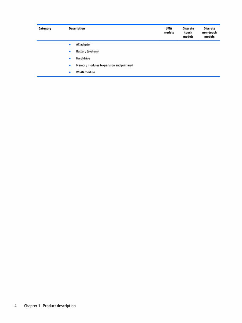
Serviceability End user replaceable parts: × × ×
3
Category Description UMAmodels
Discretetouch
models
Discretenon-touch
models
● AC adapter
● Battery (system)
● Hard drive
● Memory modules (expansion and primary)
● WLAN module
4 Chapter 1 Product description
2 External component identification
Finding your hardware and software information
Locating hardware
To find out what hardware is installed on your computer:
1. From the Start screen, type control panel, and then select Control Panel.
2. Select System and Security, select System, and then click Device Manager in the left column.
A list reveals all the devices installed in your computer.
To find out information about system hardware components and the system BIOS version number, press fn+esc.
Locating software
To find out what software is installed on your computer:
▲ From the Start screen, click the down arrow in the lower-left corner of the screen.
Finding your hardware and software information 5
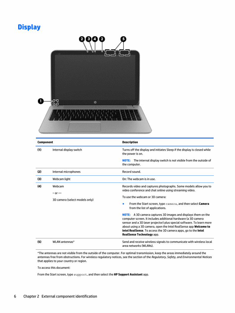
Display
Component Description
(1) Internal display switch Turns off the display and initiates Sleep if the display is closed whilethe power is on.
NOTE: The internal display switch is not visible from the outside ofthe computer.
(2) Internal microphones Record sound.
(3) Webcam light On: The webcam is in use.
(4) Webcam
– or —
3D camera (select models only)
Records video and captures photographs. Some models allow you tovideo conference and chat online using streaming video.
To use the webcam or 3D camera:
● From the Start screen, type camera, and then select Camerafrom the list of applications.
NOTE: A 3D camera captures 3D images and displays them on thecomputer screen. It includes additional hardware (a 3D camerasensor and a 3D laser projector) plus special software. To learn moreabout using a 3D camera, open the Intel RealSense app Welcome toIntel RealSense. To access the 3D camera apps, go to the IntelRealSense Technology app.
(5) WLAN antennas* Send and receive wireless signals to communicate with wireless localarea networks (WLANs).
*The antennas are not visible from the outside of the computer. For optimal transmission, keep the areas immediately around theantennas free from obstructions. For wireless regulatory notices, see the section of the Regulatory, Safety, and Environmental Noticesthat applies to your country or region.
To access this document:
From the Start screen, type support, and then select the HP Support Assistant app.
6 Chapter 2 External component identification
Component Description
– or –
From the Windows desktop, click the question mark icon in the notification area, at the far right of the taskbar.
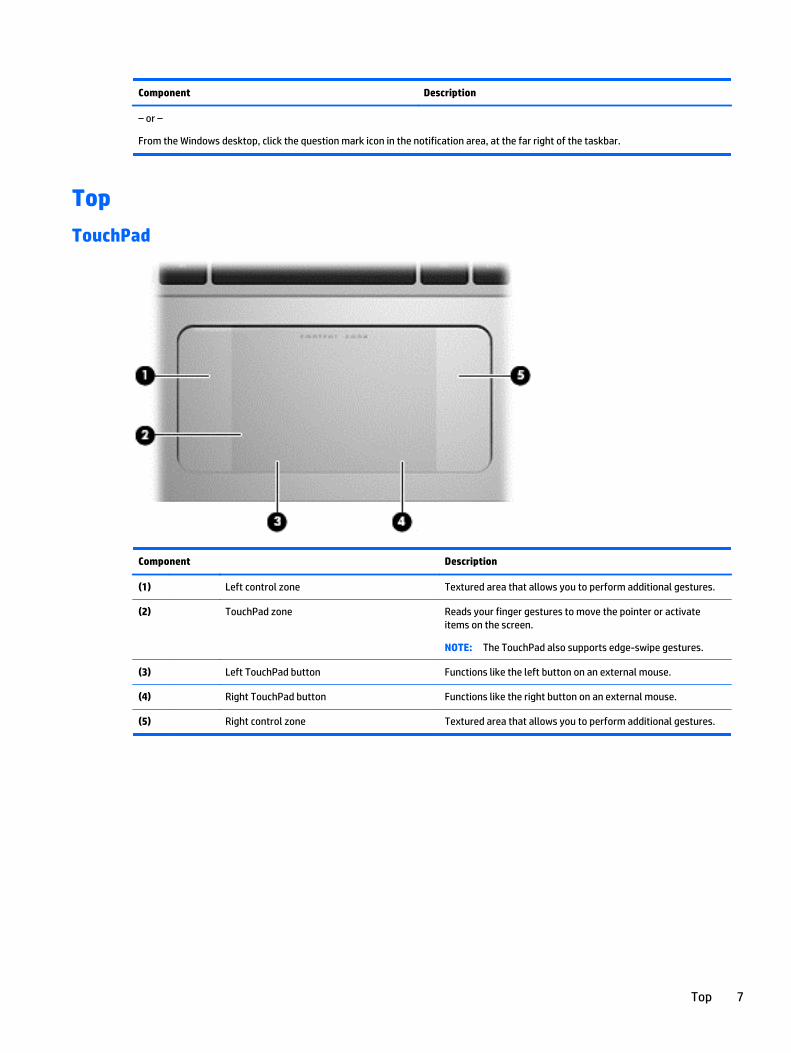
Top
TouchPad
Component Description
(1) Left control zone Textured area that allows you to perform additional gestures.
(2) TouchPad zone Reads your finger gestures to move the pointer or activateitems on the screen.
NOTE: The TouchPad also supports edge-swipe gestures.
(3) Left TouchPad button Functions like the left button on an external mouse.
(4) Right TouchPad button Functions like the right button on an external mouse.
(5) Right control zone Textured area that allows you to perform additional gestures.
Top 7
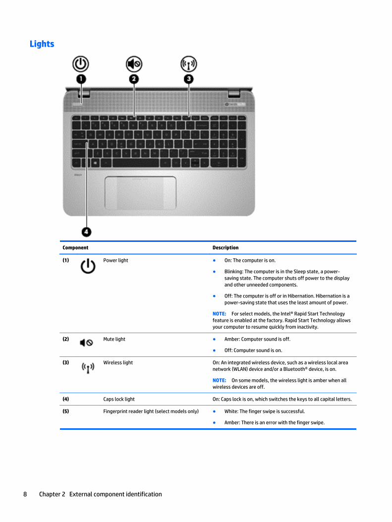
Lights
Component Description
(1) Power light ● On: The computer is on.
● Blinking: The computer is in the Sleep state, a power-saving state. The computer shuts off power to the displayand other unneeded components.
● Off: The computer is off or in Hibernation. Hibernation is apower-saving state that uses the least amount of power.
NOTE: For select models, the Intel® Rapid Start Technologyfeature is enabled at the factory. Rapid Start Technology allowsyour computer to resume quickly from inactivity.
(2) Mute light ● Amber: Computer sound is off.
● Off: Computer sound is on.
(3) Wireless light On: An integrated wireless device, such as a wireless local areanetwork (WLAN) device and/or a Bluetooth® device, is on.
NOTE: On some models, the wireless light is amber when allwireless devices are off.
(4) Caps lock light On: Caps lock is on, which switches the keys to all capital letters.
(5) Fingerprint reader light (select models only) ● White: The finger swipe is successful.
● Amber: There is an error with the finger swipe.
8 Chapter 2 External component identification
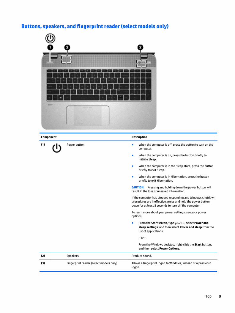
Buttons, speakers, and fingerprint reader (select models only)
Component Description
(1) Power button ● When the computer is off, press the button to turn on thecomputer.
● When the computer is on, press the button briefly toinitiate Sleep.
● When the computer is in the Sleep state, press the buttonbriefly to exit Sleep.
● When the computer is in Hibernation, press the buttonbriefly to exit Hibernation.
CAUTION: Pressing and holding down the power button willresult in the loss of unsaved information.
If the computer has stopped responding and Windows shutdownprocedures are ineffective, press and hold the power buttondown for at least 5 seconds to turn off the computer.
To learn more about your power settings, see your poweroptions:
● From the Start screen, type power, select Power andsleep settings, and then select Power and sleep from thelist of applications.
– or –
From the Windows desktop, right-click the Start button,and then select Power Options.
(2) Speakers Produce sound.
(3) Fingerprint reader (select models only) Allows a fingerprint logon to Windows, instead of a passwordlogon.
Top 9
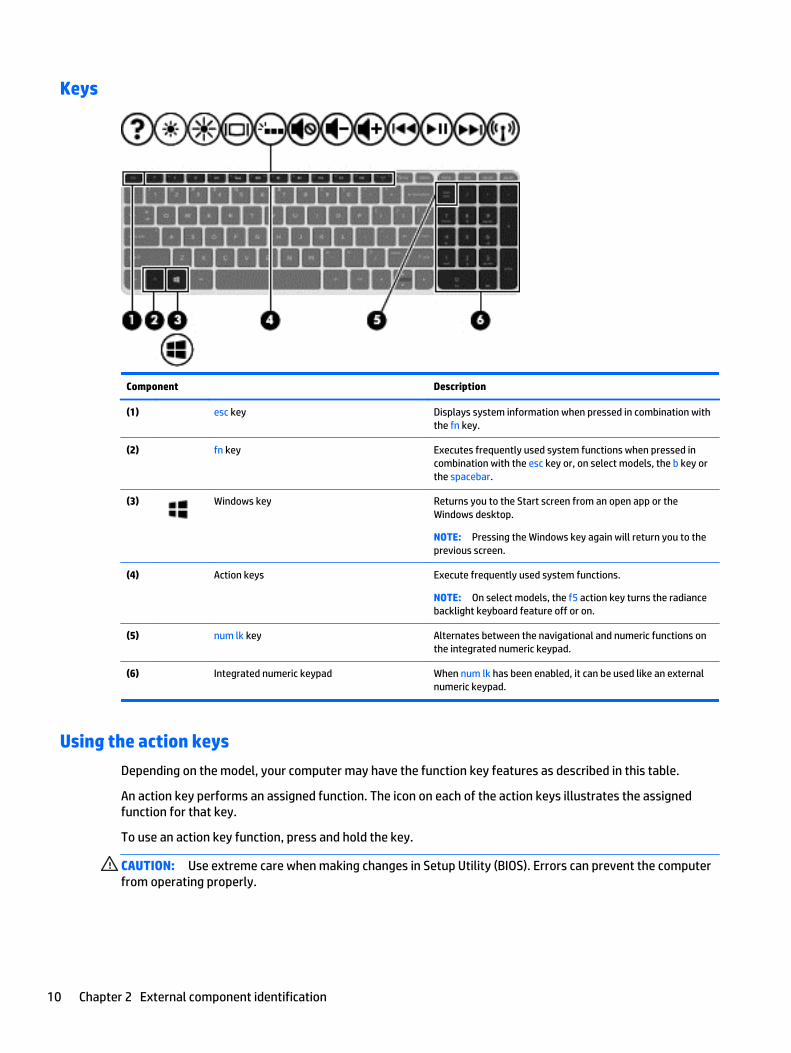
Keys
Component Description
(1) esc key Displays system information when pressed in combination withthe fn key.
(2) fn key Executes frequently used system functions when pressed incombination with the esc key or, on select models, the b key orthe spacebar.
(3) Windows key Returns you to the Start screen from an open app or theWindows desktop.
NOTE: Pressing the Windows key again will return you to theprevious screen.
(4) Action keys Execute frequently used system functions.
NOTE: On select models, the f5 action key turns the radiancebacklight keyboard feature off or on.
(5) num lk key Alternates between the navigational and numeric functions onthe integrated numeric keypad.
(6) Integrated numeric keypad When num lk has been enabled, it can be used like an externalnumeric keypad.
Using the action keys
Depending on the model, your computer may have the function key features as described in this table.
An action key performs an assigned function. The icon on each of the action keys illustrates the assignedfunction for that key.
To use an action key function, press and hold the key.
CAUTION: Use extreme care when making changes in Setup Utility (BIOS). Errors can prevent the computerfrom operating properly.
10 Chapter 2 External component identification
NOTE: The action key feature is enabled at the factory. You can disable this feature in Setup Utility (BIOS).Refer to Help and Support for additional information.
After you have disabled the action key feature, you can still perform each function by pressing the fn key incombination with the appropriate action key.
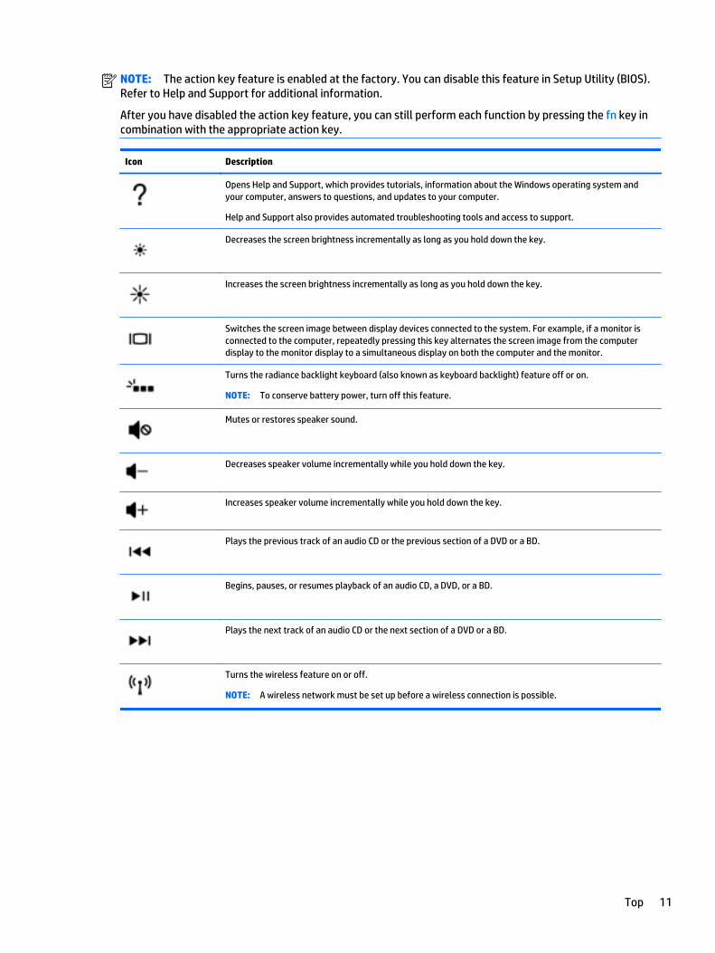
Icon Description
Opens Help and Support, which provides tutorials, information about the Windows operating system andyour computer, answers to questions, and updates to your computer.
Help and Support also provides automated troubleshooting tools and access to support.
Decreases the screen brightness incrementally as long as you hold down the key.
Increases the screen brightness incrementally as long as you hold down the key.
Switches the screen image between display devices connected to the system. For example, if a monitor isconnected to the computer, repeatedly pressing this key alternates the screen image from the computerdisplay to the monitor display to a simultaneous display on both the computer and the monitor.
Turns the radiance backlight keyboard (also known as keyboard backlight) feature off or on.
NOTE: To conserve battery power, turn off this feature.
Mutes or restores speaker sound.
Decreases speaker volume incrementally while you hold down the key.
Increases speaker volume incrementally while you hold down the key.
Plays the previous track of an audio CD or the previous section of a DVD or a BD.
Begins, pauses, or resumes playback of an audio CD, a DVD, or a BD.
Plays the next track of an audio CD or the next section of a DVD or a BD.
Turns the wireless feature on or off.
NOTE: A wireless network must be set up before a wireless connection is possible.
Top 11
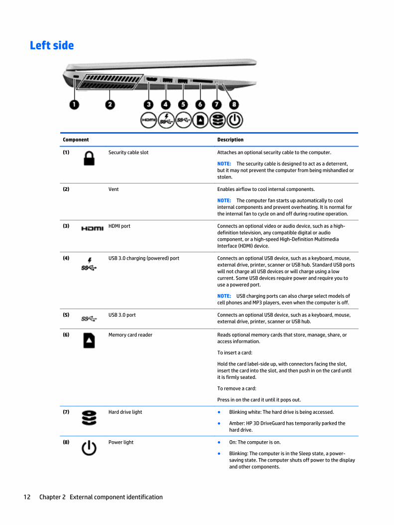
Left side
Component Description
(1) Security cable slot Attaches an optional security cable to the computer.
NOTE: The security cable is designed to act as a deterrent,but it may not prevent the computer from being mishandled orstolen.
(2) Vent Enables airflow to cool internal components.
NOTE: The computer fan starts up automatically to coolinternal components and prevent overheating. It is normal forthe internal fan to cycle on and off during routine operation.
(3) HDMI port Connects an optional video or audio device, such as a high-definition television, any compatible digital or audiocomponent, or a high-speed High-Definition MultimediaInterface (HDMI) device.
(4) USB 3.0 charging (powered) port Connects an optional USB device, such as a keyboard, mouse,external drive, printer, scanner or USB hub. Standard USB portswill not charge all USB devices or will charge using a lowcurrent. Some USB devices require power and require you touse a powered port.
NOTE: USB charging ports can also charge select models ofcell phones and MP3 players, even when the computer is off.
(5) USB 3.0 port Connects an optional USB device, such as a keyboard, mouse,external drive, printer, scanner or USB hub.
(6) Memory card reader Reads optional memory cards that store, manage, share, oraccess information.
To insert a card:
Hold the card label-side up, with connectors facing the slot,insert the card into the slot, and then push in on the card untilit is firmly seated.
To remove a card:
Press in on the card it until it pops out.
(7) Hard drive light ● Blinking white: The hard drive is being accessed.
● Amber: HP 3D DriveGuard has temporarily parked thehard drive.
(8) Power light ● On: The computer is on.
● Blinking: The computer is in the Sleep state, a power-saving state. The computer shuts off power to the displayand other components.
12 Chapter 2 External component identification
Component Description
● Off: The computer is off or in Hibernation. Hibernation is apower-saving state that uses the least amount of power.
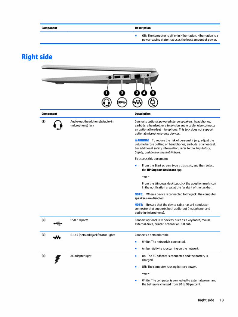
Right side
Component Description
(1) Audio-out (headphone)/Audio-in(microphone) jack
Connects optional powered stereo speakers, headphones,earbuds, a headset, or a television audio cable. Also connectsan optional headset microphone. This jack does not supportoptional microphone-only devices.
WARNING! To reduce the risk of personal injury, adjust thevolume before putting on headphones, earbuds, or a headset.For additional safety information, refer to the Regulatory,Safety, and Environmental Notices.
To access this document:
● From the Start screen, type support, and then selectthe HP Support Assistant app.
– or –
From the Windows desktop, click the question mark iconin the notification area, at the far right of the taskbar.
NOTE: When a device is connected to the jack, the computerspeakers are disabled.
NOTE: Be sure that the device cable has a 4-conductorconnector that supports both audio-out (headphone) andaudio-in (microphone).
(2) USB 2.0 ports Connect optional USB devices, such as a keyboard, mouse,external drive, printer, scanner or USB hub.
(3) RJ-45 (network) jack/status lights Connects a network cable.
● White: The network is connected.
● Amber: Activity is occurring on the network.
(4) AC adapter light ● On: The AC adapter is connected and the battery ischarged.
● Off: The computer is using battery power.
– or –
● White: The computer is connected to external power andthe battery is charged from 90 to 99 percent.
Right side 13
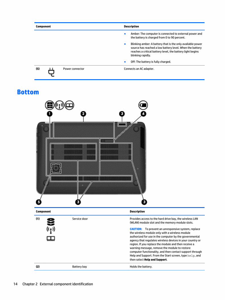
Component Description
● Amber: The computer is connected to external power andthe battery is charged from 0 to 90 percent.
● Blinking amber: A battery that is the only available powersource has reached a low battery level. When the batteryreaches a critical battery level, the battery light beginsblinking rapidly.
● Off: The battery is fully charged.
(5) Power connector Connects an AC adapter.
Bottom
Component Description
(1) Service door Provides access to the hard drive bay, the wireless LAN(WLAN) module slot and the memory module slots.
CAUTION: To prevent an unresponsive system, replacethe wireless module only with a wireless moduleauthorized for use in the computer by the governmentalagency that regulates wireless devices in your country orregion. If you replace the module and then receive awarning message, remove the module to restorecomputer functionality, and then contact support throughHelp and Support. From the Start screen, type help, andthen select Help and Support.
(2) Battery bay Holds the battery.
14 Chapter 2 External component identification
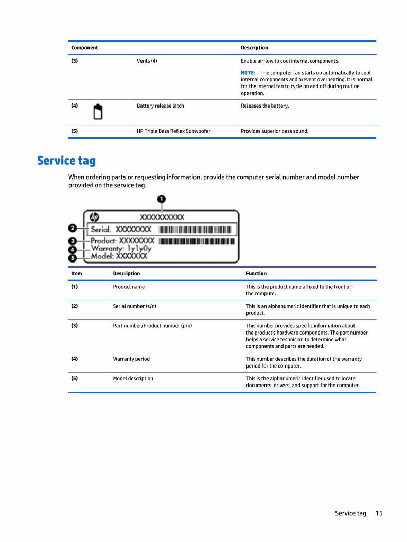
Component Description
(3) Vents (4) Enable airflow to cool internal components.
NOTE: The computer fan starts up automatically to coolinternal components and prevent overheating. It is normalfor the internal fan to cycle on and off during routineoperation.
(4) Battery release latch Releases the battery.
(5) HP Triple Bass Reflex Subwoofer Provides superior bass sound.
Service tagWhen ordering parts or requesting information, provide the computer serial number and model numberprovided on the service tag.
Item Description Function
(1) Product name This is the product name affixed to the front ofthe computer.
(2) Serial number (s/n) This is an alphanumeric identifier that is unique to eachproduct.
(3) Part number/Product number (p/n) This number provides specific information aboutthe product's hardware components. The part numberhelps a service technician to determine whatcomponents and parts are needed.
(4) Warranty period This number describes the duration of the warrantyperiod for the computer.
(5) Model description This is the alphanumeric identifier used to locatedocuments, drivers, and support for the computer.
Service tag 15
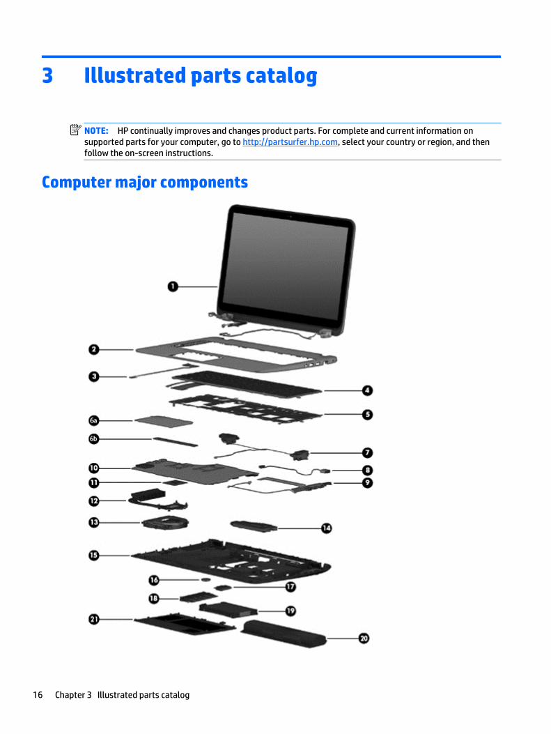
3 Illustrated parts catalog
NOTE: HP continually improves and changes product parts. For complete and current information onsupported parts for your computer, go to http://partsurfer.hp.com, select your country or region, and thenfollow the on-screen instructions.
Computer major components
16 Chapter 3 Illustrated parts catalog
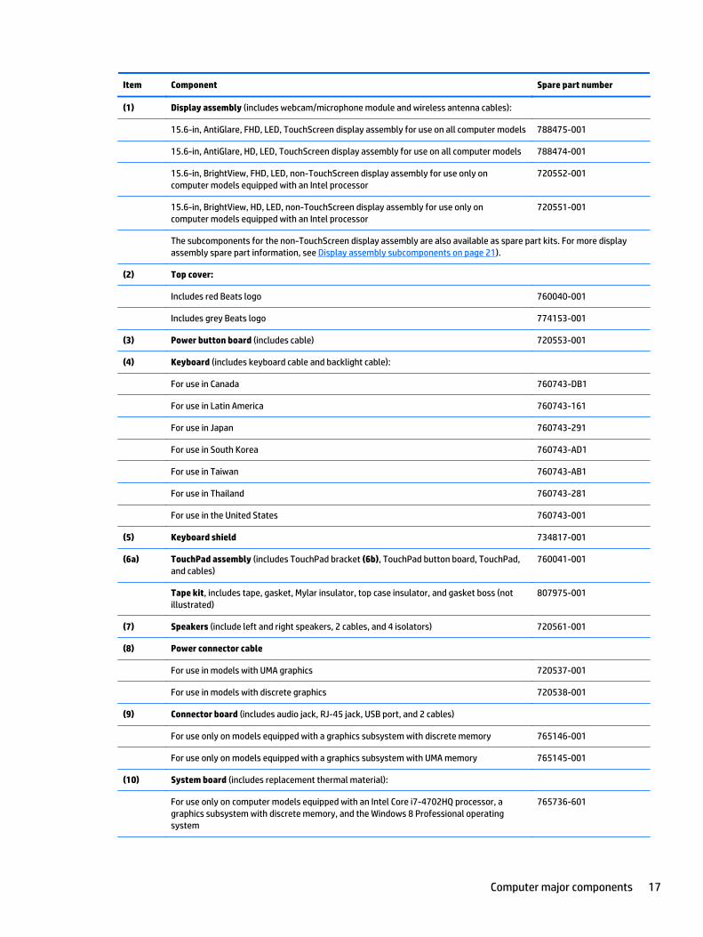
Item Component Spare part number
(1) Display assembly (includes webcam/microphone module and wireless antenna cables):
15.6-in, AntiGlare, FHD, LED, TouchScreen display assembly for use on all computer models 788475-001
15.6-in, AntiGlare, HD, LED, TouchScreen display assembly for use on all computer models 788474-001
15.6-in, BrightView, FHD, LED, non-TouchScreen display assembly for use only oncomputer models equipped with an Intel processor
720552-001
15.6-in, BrightView, HD, LED, non-TouchScreen display assembly for use only oncomputer models equipped with an Intel processor
720551-001
The subcomponents for the non-TouchScreen display assembly are also available as spare part kits. For more displayassembly spare part information, see Display assembly subcomponents on page 21).
(2) Top cover:
Includes red Beats logo 760040-001
Includes grey Beats logo 774153-001
(3) Power button board (includes cable) 720553-001
(4) Keyboard (includes keyboard cable and backlight cable):
For use in Canada 760743-DB1
For use in Latin America 760743-161
For use in Japan 760743-291
For use in South Korea 760743-AD1
For use in Taiwan 760743-AB1
For use in Thailand 760743-281
For use in the United States 760743-001
(5) Keyboard shield 734817-001
(6a) TouchPad assembly (includes TouchPad bracket (6b), TouchPad button board, TouchPad,and cables)
760041-001
Tape kit, includes tape, gasket, Mylar insulator, top case insulator, and gasket boss (notillustrated)
807975-001
(7) Speakers (include left and right speakers, 2 cables, and 4 isolators) 720561-001
(8) Power connector cable
For use in models with UMA graphics 720537-001
For use in models with discrete graphics 720538-001
(9) Connector board (includes audio jack, RJ-45 jack, USB port, and 2 cables)
For use only on models equipped with a graphics subsystem with discrete memory 765146-001
For use only on models equipped with a graphics subsystem with UMA memory 765145-001
(10) System board (includes replacement thermal material):
For use only on computer models equipped with an Intel Core i7-4702HQ processor, agraphics subsystem with discrete memory, and the Windows 8 Professional operatingsystem
765736-601
Computer major components 17
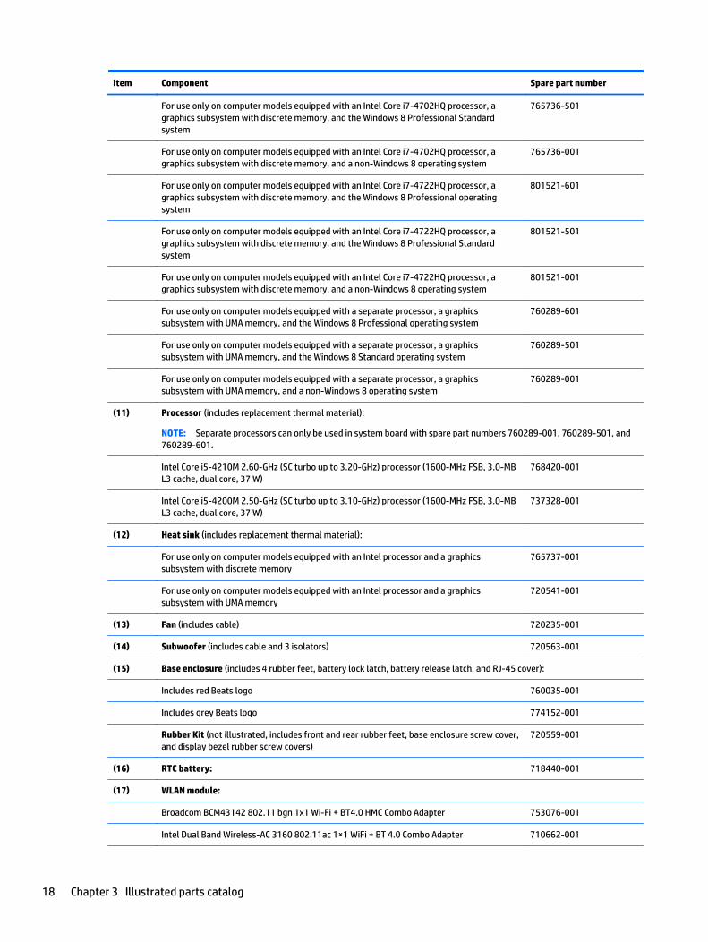
Item Component Spare part number
For use only on computer models equipped with an Intel Core i7-4702HQ processor, agraphics subsystem with discrete memory, and the Windows 8 Professional Standardsystem
765736-501
For use only on computer models equipped with an Intel Core i7-4702HQ processor, agraphics subsystem with discrete memory, and a non-Windows 8 operating system
765736-001
For use only on computer models equipped with an Intel Core i7-4722HQ processor, agraphics subsystem with discrete memory, and the Windows 8 Professional operatingsystem
801521-601
For use only on computer models equipped with an Intel Core i7-4722HQ processor, agraphics subsystem with discrete memory, and the Windows 8 Professional Standardsystem
801521-501
For use only on computer models equipped with an Intel Core i7-4722HQ processor, agraphics subsystem with discrete memory, and a non-Windows 8 operating system
801521-001
For use only on computer models equipped with a separate processor, a graphicssubsystem with UMA memory, and the Windows 8 Professional operating system
760289-601
For use only on computer models equipped with a separate processor, a graphicssubsystem with UMA memory, and the Windows 8 Standard operating system
760289-501
For use only on computer models equipped with a separate processor, a graphicssubsystem with UMA memory, and a non-Windows 8 operating system
760289-001
(11) Processor (includes replacement thermal material):
NOTE: Separate processors can only be used in system board with spare part numbers 760289-001, 760289-501, and760289-601.
Intel Core i5-4210M 2.60-GHz (SC turbo up to 3.20-GHz) processor (1600-MHz FSB, 3.0-MBL3 cache, dual core, 37 W)
768420-001
Intel Core i5-4200M 2.50-GHz (SC turbo up to 3.10-GHz) processor (1600-MHz FSB, 3.0-MBL3 cache, dual core, 37 W)
737328-001
(12) Heat sink (includes replacement thermal material):
For use only on computer models equipped with an Intel processor and a graphicssubsystem with discrete memory
765737-001
For use only on computer models equipped with an Intel processor and a graphicssubsystem with UMA memory
720541-001
(13) Fan (includes cable) 720235-001
(14) Subwoofer (includes cable and 3 isolators) 720563-001
(15) Base enclosure (includes 4 rubber feet, battery lock latch, battery release latch, and RJ-45 cover):
Includes red Beats logo 760035-001
Includes grey Beats logo 774152-001
Rubber Kit (not illustrated, includes front and rear rubber feet, base enclosure screw cover,and display bezel rubber screw covers)
720559-001
(16) RTC battery: 718440-001
(17) WLAN module:
Broadcom BCM43142 802.11 bgn 1x1 Wi-Fi + BT4.0 HMC Combo Adapter 753076-001
Intel Dual Band Wireless-AC 3160 802.11ac 1×1 WiFi + BT 4.0 Combo Adapter 710662-001
18 Chapter 3 Illustrated parts catalog
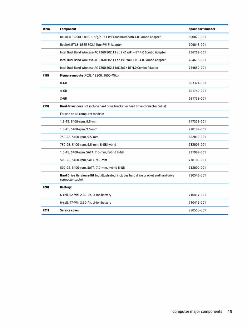
Item Component Spare part number
Ralink RT3290LE 802.11b/g/n 1×1 WiFi and Bluetooth 4.0 Combo Adapter 690020-001
Realtek RTL8188EE 802.11bgn Wi-Fi Adapter 709848-001
Intel Dual Band Wireless-AC 7260 802.11 ac 2×2 WiFi + BT 4.0 Combo Adapter 756753-001
Intel Dual Band Wireless-AC 3160 802.11 ac 1x1 WiFi + BT 4.0 Combo Adapter 784638-001
Intel Dual Band Wireless-AC 7260 802.11AC 2x2+ BT 4.0 Combo Adapter 784650-001
(18) Memory module (PC3L, 12800, 1600-MHz):
8-GB 693374-001
4-GB 691740-001
2-GB 691739-001
(19) Hard drive (does not include hard drive bracket or hard drive connector cable):
For use on all computer models:
1.5-TB, 5400-rpm, 9.5-mm 747375-001
1.0-TB, 5400-rpm, 9.5-mm 778192-001
750-GB, 5400-rpm, 9.5-mm 652012-001
750-GB, 5400-rpm, 9.5-mm, 8-GB hybrid 732001-001
1.0-TB, 5400-rpm, SATA, 7.0-mm, hybrid 8-GB 731999-001
500-GB, 5400-rpm, SATA, 9.5-mm 778186-001
500-GB, 5400-rpm, SATA, 7.0-mm, hybrid 8-GB 732000-001
Hard Drive Hardware Kit (not illustrated, includes hard drive bracket and hard driveconnector cable)
720545-001
(20) Battery:
6-cell, 62-Wh, 2.80-Ah, Li-ion battery 710417-001
6-cell, 47-Wh, 2.20-Ah, Li-ion battery 710416-001
(21) Service cover 720555-001
Computer major components 19
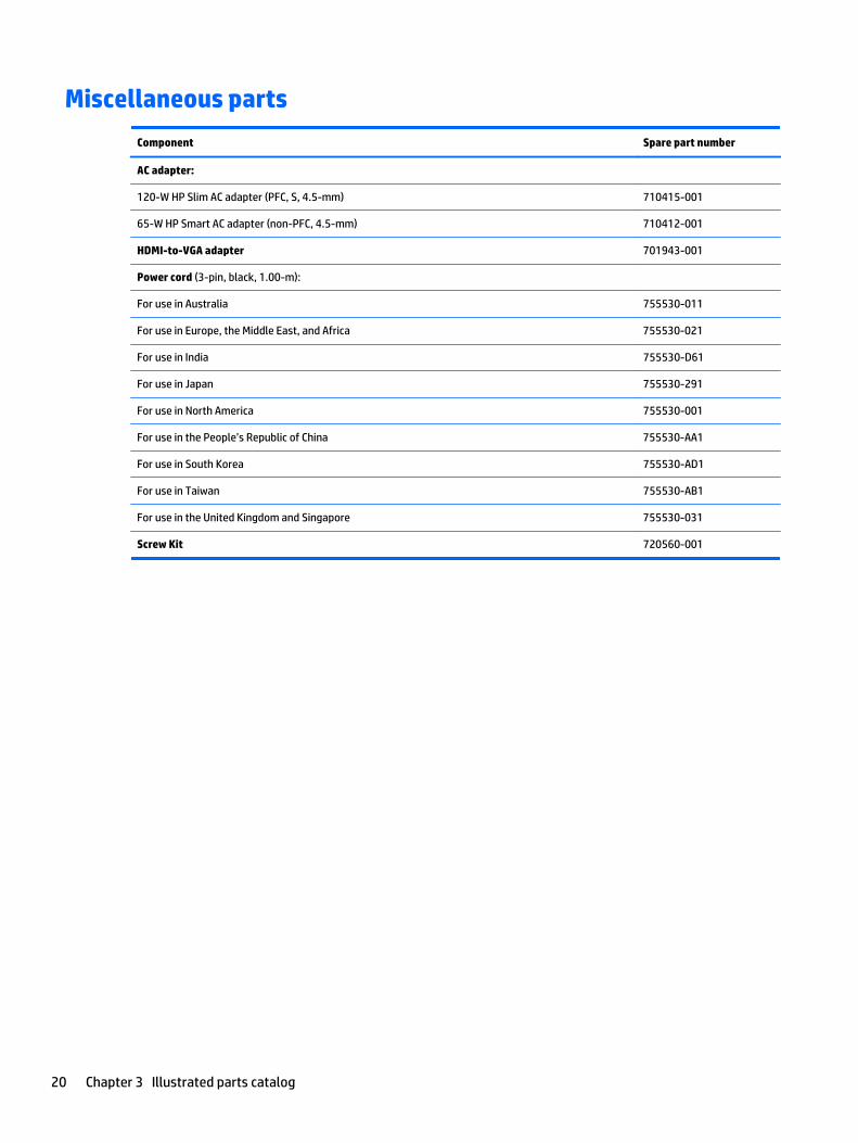
Miscellaneous parts
Component Spare part number
AC adapter:
120-W HP Slim AC adapter (PFC, S, 4.5-mm) 710415-001
65-W HP Smart AC adapter (non-PFC, 4.5-mm) 710412-001
HDMI-to-VGA adapter 701943-001
Power cord (3-pin, black, 1.00-m):
For use in Australia 755530-011
For use in Europe, the Middle East, and Africa 755530-021
For use in India 755530-D61
For use in Japan 755530-291
For use in North America 755530-001
For use in the People’s Republic of China 755530-AA1
For use in South Korea 755530-AD1
For use in Taiwan 755530-AB1
For use in the United Kingdom and Singapore 755530-031
Screw Kit 720560-001
20 Chapter 3 Illustrated parts catalog
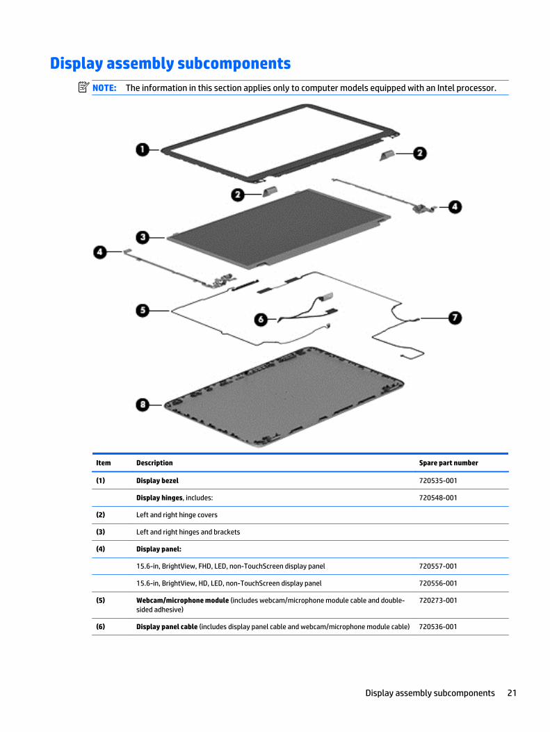
Display assembly subcomponentsNOTE: The information in this section applies only to computer models equipped with an Intel processor.
Item Description Spare part number
(1) Display bezel 720535-001
Display hinges, includes: 720548-001
(2) Left and right hinge covers
(3) Left and right hinges and brackets
(4) Display panel:
15.6-in, BrightView, FHD, LED, non-TouchScreen display panel 720557-001
15.6-in, BrightView, HD, LED, non-TouchScreen display panel 720556-001
(5) Webcam/microphone module (includes webcam/microphone module cable and double-sided adhesive)
720273-001
(6) Display panel cable (includes display panel cable and webcam/microphone module cable) 720536-001
Display assembly subcomponents 21
Item Description Spare part number
(7) Antenna Kit (includes left and right wireless antenna cables and transceivers) 720532-001
(8) Display enclosure 720533-001
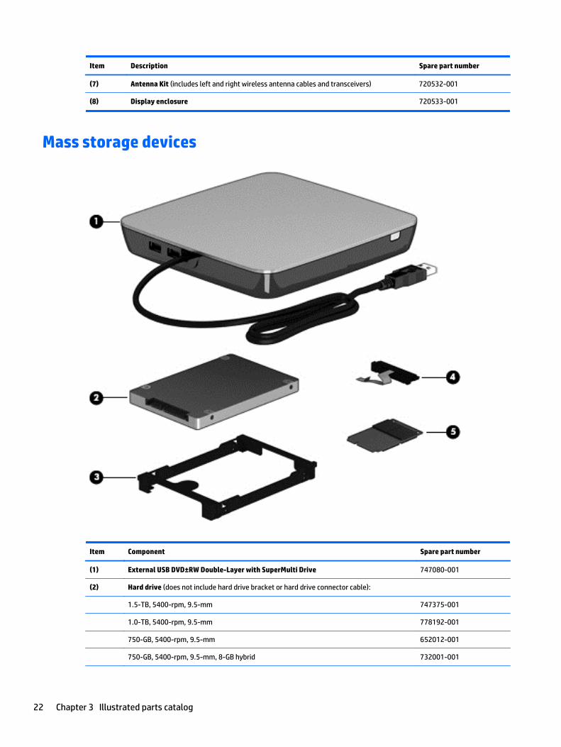
Mass storage devices
Item Component Spare part number
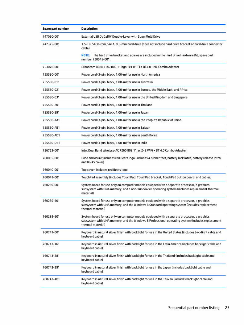
(1) External USB DVD±RW Double-Layer with SuperMulti Drive 747080-001
(2) Hard drive (does not include hard drive bracket or hard drive connector cable):
1.5-TB, 5400-rpm, 9.5-mm 747375-001
1.0-TB, 5400-rpm, 9.5-mm 778192-001
750-GB, 5400-rpm, 9.5-mm 652012-001
750-GB, 5400-rpm, 9.5-mm, 8-GB hybrid 732001-001
22 Chapter 3 Illustrated parts catalog
Item Component Spare part number
1.0-TB, 5400-rpm, SATA, 7.0-mm, hybrid 8-GB 731999-001
500-GB, 5400-rpm, SATA, 9.5-mm 778186-001
500-GB, 5400-rpm, SATA, 7.0-mm, hybrid 8-GB 732000-001
Hard Drive Hardware Kit, includes: 720545-001
(3) Hard drive bracket
(4) Hard drive connector cable
Sequential part number listing
Spare part number Description
652012-001 750-GB, 5400-rpm, SATA, 9.5-mm hard drive for use on all computer models (does not include hard drivebracket or hard drive connector cable)
NOTE: The hard drive bracket and screws are included in the Hard Drive Hardware Kit, spare partnumber 720545-001.
690020-001 Ralink RT3290LE 802.11b/g/n 1×1 WiFi and Bluetooth 4.0 Combo Adapter for use only oncomputer models equipped with an Intel processor
691739-001 2-GB memory module (PC3L, 12800, 1600-MHz)
691740-001 4-GB memory module (PC3L, 12800, 1600-MHz)
693374-001 8-GB memory module (PC3L, 12800, 1600-MHz)
701943-001 HDMI-to-VGA adapter
709848-001 Realtek RTL8188EE 802.11bgn Wi-Fi Adapter for use only on computer models equipped with an Intelprocessor
710412-001 65-W HP Smart AC adapter (non-PFC, 4.5-mm)
710415-001 120-W HP Slim AC adapter (PFC, S, 4.5-mm)
710416-001 6-cell, 47-Wh, 2.20-Ah, Li-ion battery
710417-001 6-cell, 62-Wh, 2.80-Ah, Li-ion battery
710662-001 Intel Dual Band Wireless-AC 3160 802.11ac 1×1 WiFi + BT 4.0 Combo Adapter for use only oncomputer models equipped with an Intel processor
718440-001 RTC battery
720235-001 Fan (includes cable)
720273-001 Webcam/microphone module (for use only on computer models equipped with an Intel processor and anon-TouchScreen display assembly)
720532-001 Antenna Kit (for use only on computer models equipped with an Intel processor and a non-TouchScreendisplay assembly; includes left and right wireless antenna cables and transceivers)
720533-001 Display enclosure (for use only on computer models equipped with an Intel processor and a non-TouchScreen display assembly)
720535-001 Display bezel (for use only on computer models equipped with an Intel processor and a non-TouchScreendisplay assembly)
Sequential part number listing 23
Spare part number Description
720536-001 Display panel cable (for use only on computer models equipped with an Intel processor and a non-TouchScreen display assembly; includes display panel cable and webcam/microphone module cable)
720537-001 Power connector cable for use in models with UMA graphics
720538-001 Power connector cable for use in models with discrete graphics
720541-001 Heat sink for use only on computer models equipped with a graphic subsystem with discrete memory(includes replacement thermal material)
720545-001 Hard Drive Hardware Kit (includes hard drive bracket and hard drive connector cable)
720547-001 Counterbalance weight
720548-001 Display Hinge Kit (for use only on computer models equipped with an Intel processor and a non-TouchScreen display assembly; includes left and right display hinges and hinge brackets)
720551-001 15.6-in, BrightView, HD, LED, non-TouchScreen display assembly for use only on computer modelsequipped with an Intel processor (includes webcam/microphone module and wireless antenna cables)
720552-001 15.6-in, BrightView, FHD, LED, non-TouchScreen display assembly for use only on computer modelsequipped with an Intel processor (includes webcam/microphone module and wireless antenna cables)
720553-001 Power button board (includes cable)
720555-001 Service cover
720556-001 15.6-in, BrightView, HD, LED, non-TouchScreen display panel for use only on computer models equippedwith an Intel processor
720557-001 15.6-in, BrightView, FHD, LED, non-TouchScreen display panel for use only on computer models equippedwith an Intel processor
720559-001 Rubber Kit (includes front and rear rubber feet, base enclosure screw cover, and display bezel rubberscrew covers)
720560-001 Screw Kit
720561-001 Speakers (include left and right speakers, 2 cables, and 4 isolators)
720563-001 Subwoofer (includes cable and 3 rubber isolators)
731999-001 1-TB, 5400-rpm, SATA, 7.0-mm, hybrid 8-GB hard drive (does not include hard drive bracket or hard driveconnector cable)
NOTE: The hard drive bracket and screws are included in the Hard Drive Hardware Kit, spare partnumber 720545-001.
732000-001 500-GB, 5400-rpm, SATA, 7.0-mm, hybrid 8-GB hard drive (does not include hard drive bracket or harddrive connector cable)
NOTE: The hard drive bracket and screws are included in the Hard Drive Hardware Kit, spare partnumber 720545-001.
732001-001 750-GB, 5400-rpm, SATA, 9.5-mm 8-GB hybrid hard drive (does not include hard drive bracket or harddrive connector cable)
NOTE: The hard drive bracket and screws are included in the Hard Drive Hardware Kit, spare partnumber 720545-001.
734817-001 Keyboard shield
737328-001 Intel Core i5-4200M 2.50-GHz (SC turbo up to 3.10-GHz) processor (1600-MHz FSB, 3.0-MB L3 cache, dualcore, 37 W; includes replacement thermal material)
NOTE: Separate processors can only be used in system board with spare part numbers 760289-001,760289-501, and 760289-601.
24 Chapter 3 Illustrated parts catalog
Spare part number Description
747080-001 External USB DVD±RW Double-Layer with SuperMulti Drive
747375-001 1.5-TB, 5400-rpm, SATA, 9.5-mm hard drive (does not include hard drive bracket or hard drive connectorcable)
NOTE: The hard drive bracket and screws are included in the Hard Drive Hardware Kit, spare partnumber 720545-001.
753076-001 Broadcom BCM43142 802.11 bgn 1x1 Wi-Fi + BT4.0 HMC Combo Adapter
755530-001 Power cord (3-pin, black, 1.00-m) for use in North America
755530-011 Power cord (3-pin, black, 1.00-m) for use in Australia
755530-021 Power cord (3-pin, black, 1.00-m) for use in Europe, the Middle East, and Africa
755530-031 Power cord (3-pin, black, 1.00-m) for use in the United Kingdom and Singapore
755530-201 Power cord (3-pin, black, 1.00-m) for use in Thailand
755530-291 Power cord (3-pin, black, 1.00-m) for use in Japan
755530-AA1 Power cord (3-pin, black, 1.00-m) for use in the People’s Republic of China
755530-AB1 Power cord (3-pin, black, 1.00-m) for use in Taiwan
755530-AD1 Power cord (3-pin, black, 1.00-m) for use in South Korea
755530-D61 Power cord (3-pin, black, 1.00-m) for use in India
756753-001 Intel Dual Band Wireless-AC 7260 802.11 ac 2×2 WiFi + BT 4.0 Combo Adapter
760035-001 Base enclosure; includes red Beats logo (includes 4 rubber feet, battery lock latch, battery release latch,and RJ-45 cover)
760040-001 Top cover; includes red Beats logo
760041-001 TouchPad assembly (includes TouchPad, TouchPad bracket, TouchPad button board, and cables)
760289-001 System board for use only on computer models equipped with a separate processor, a graphicssubsystem with UMA memory, and a non-Windows 8 operating system (includes replacement thermalmaterial)
760289-501 System board for use only on computer models equipped with a separate processor, a graphicssubsystem with UMA memory, and the Windows 8 Standard operating system (includes replacementthermal material)
760289-601 System board for use only on computer models equipped with a separate processor, a graphicssubsystem with UMA memory, and the Windows 8 Professional operating system (includes replacementthermal material)
760743-001 Keyboard in natural silver finish with backlight for use in the United States (includes backlight cable andkeyboard cable)
760743-161 Keyboard in natural silver finish with backlight for use in the Latin America (includes backlight cable andkeyboard cable)
760743-281 Keyboard in natural silver finish with backlight for use in the Thailand (includes backlight cable andkeyboard cable)
760743-291 Keyboard in natural silver finish with backlight for use in the Japan (includes backlight cable andkeyboard cable)
760743-AB1 Keyboard in natural silver finish with backlight for use in the Taiwan (includes backlight cable andkeyboard cable)
Sequential part number listing 25
Spare part number Description
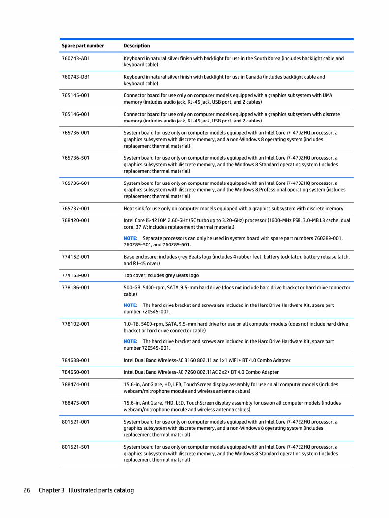
760743-AD1 Keyboard in natural silver finish with backlight for use in the South Korea (includes backlight cable andkeyboard cable)
760743-DB1 Keyboard in natural silver finish with backlight for use in Canada (includes backlight cable andkeyboard cable)
765145-001 Connector board for use only on computer models equipped with a graphics subsystem with UMAmemory (includes audio jack, RJ-45 jack, USB port, and 2 cables)
765146-001 Connector board for use only on computer models equipped with a graphics subsystem with discretememory (includes audio jack, RJ-45 jack, USB port, and 2 cables)
765736-001 System board for use only on computer models equipped with an Intel Core i7-4702HQ processor, agraphics subsystem with discrete memory, and a non-Windows 8 operating system (includesreplacement thermal material)
765736-501 System board for use only on computer models equipped with an Intel Core i7-4702HQ processor, agraphics subsystem with discrete memory, and the Windows 8 Standard operating system (includesreplacement thermal material)
765736-601 System board for use only on computer models equipped with an Intel Core i7-4702HQ processor, agraphics subsystem with discrete memory, and the Windows 8 Professional operating system (includesreplacement thermal material)
765737-001 Heat sink for use only on computer models equipped with a graphics subsystem with discrete memory
768420-001 Intel Core i5-4210M 2.60-GHz (SC turbo up to 3.20-GHz) processor (1600-MHz FSB, 3.0-MB L3 cache, dualcore, 37 W; includes replacement thermal material)
NOTE: Separate processors can only be used in system board with spare part numbers 760289-001,760289-501, and 760289-601.
774152-001 Base enclosure; includes grey Beats logo (includes 4 rubber feet, battery lock latch, battery release latch,and RJ-45 cover)
774153-001 Top cover; ncludes grey Beats logo
778186-001 500-GB, 5400-rpm, SATA, 9.5-mm hard drive (does not include hard drive bracket or hard drive connectorcable)
NOTE: The hard drive bracket and screws are included in the Hard Drive Hardware Kit, spare partnumber 720545-001.
778192-001 1.0-TB, 5400-rpm, SATA, 9.5-mm hard drive for use on all computer models (does not include hard drivebracket or hard drive connector cable)
NOTE: The hard drive bracket and screws are included in the Hard Drive Hardware Kit, spare partnumber 720545-001.
784638-001 Intel Dual Band Wireless-AC 3160 802.11 ac 1x1 WiFi + BT 4.0 Combo Adapter
784650-001 Intel Dual Band Wireless-AC 7260 802.11AC 2x2+ BT 4.0 Combo Adapter
788474-001 15.6-in, AntiGlare, HD, LED, TouchScreen display assembly for use on all computer models (includeswebcam/microphone module and wireless antenna cables)
788475-001 15.6-in, AntiGlare, FHD, LED, TouchScreen display assembly for use on all computer models (includeswebcam/microphone module and wireless antenna cables)
801521-001 System board for use only on computer models equipped with an Intel Core i7-4722HQ processor, agraphics subsystem with discrete memory, and a non-Windows 8 operating system (includesreplacement thermal material)
801521-501 System board for use only on computer models equipped with an Intel Core i7-4722HQ processor, agraphics subsystem with discrete memory, and the Windows 8 Standard operating system (includesreplacement thermal material)
26 Chapter 3 Illustrated parts catalog
Spare part number Description
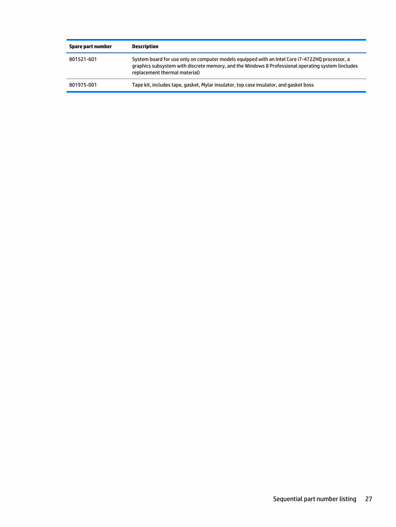
801521-601 System board for use only on computer models equipped with an Intel Core i7-4722HQ processor, agraphics subsystem with discrete memory, and the Windows 8 Professional operating system (includesreplacement thermal material)
801975-001 Tape kit, includes tape, gasket, Mylar insulator, top case insulator, and gasket boss
Sequential part number listing 27
4 Removal and replacement procedurespreliminary requirements
Tools requiredYou will need the following tools to complete the removal and replacement procedures:
● Flat-bladed screw driver
● Magnetic screw driver
● Phillips P0 and P1 screw drivers
Service considerationsThe following sections include some of the considerations that you must keep in mind during disassemblyand assembly procedures.
NOTE: As you remove each subassembly from the computer, place the subassembly (and all accompanyingscrews) away from the work area to prevent damage.
Plastic parts
CAUTION: Using excessive force during disassembly and reassembly can damage plastic parts. Use carewhen handling the plastic parts. Apply pressure only at the points designated in the maintenanceinstructions.
28 Chapter 4 Removal and replacement procedures preliminary requirements
Cables and connectors
CAUTION: When servicing the computer, be sure that cables are placed in their proper locations during thereassembly process. Improper cable placement can damage the computer.
Cables must be handled with extreme care to avoid damage. Apply only the tension required to unseat orseat the cables during removal and insertion. Handle cables by the connector whenever possible. In all cases,avoid bending, twisting, or tearing cables. Be sure that cables are routed in such a way that they cannot becaught or snagged by parts being removed or replaced. Handle flex cables with extreme care; these cablestear easily.
Drive handling
CAUTION: Drives are fragile components that must be handled with care. To prevent damage to thecomputer, damage to a drive, or loss of information, observe these precautions:
Before removing or inserting a hard drive, shut down the computer. If you are unsure whether the computeris off or in Hibernation, turn the computer on, and then shut it down through the operating system.
Before handling a drive, be sure that you are discharged of static electricity. While handling a drive, avoidtouching the connector.
Before removing a diskette drive or optical drive, be sure that a diskette or disc is not in the drive and be surethat the optical drive tray is closed.
Handle drives on surfaces covered with at least one inch of shock-proof foam.
Avoid dropping drives from any height onto any surface.
After removing a hard drive, an optical drive, or a diskette drive, place it in a static-proof bag.
Avoid exposing an internal hard drive to products that have magnetic fields, such as monitors or speakers.
Avoid exposing a drive to temperature extremes or liquids.
If a drive must be mailed, place the drive in a bubble pack mailer or other suitable form of protectivepackaging and label the package “FRAGILE.”
Grounding guidelines
Electrostatic discharge damage
Electronic components are sensitive to electrostatic discharge (ESD). Circuitry design and structuredetermine the degree of sensitivity. Networks built into many integrated circuits provide some protection,but in many cases, ESD contains enough power to alter device parameters or melt silicon junctions.
A discharge of static electricity from a finger or other conductor can destroy static-sensitive devices ormicrocircuitry. Even if the spark is neither felt nor heard, damage may have occurred.
An electronic device exposed to ESD may not be affected at all and can work perfectly throughout a normalcycle. Or the device may function normally for a while, then degrade in the internal layers, reducing its lifeexpectancy.
Grounding guidelines 29
CAUTION: To prevent damage to the computer when you are removing or installing internal components,observe these precautions:
Keep components in their electrostatic-safe containers until you are ready to install them.
Before touching an electronic component, discharge static electricity by using the guidelines described in thissection.
Avoid touching pins, leads, and circuitry. Handle electronic components as little as possible.
If you remove a component, place it in an electrostatic-safe container.
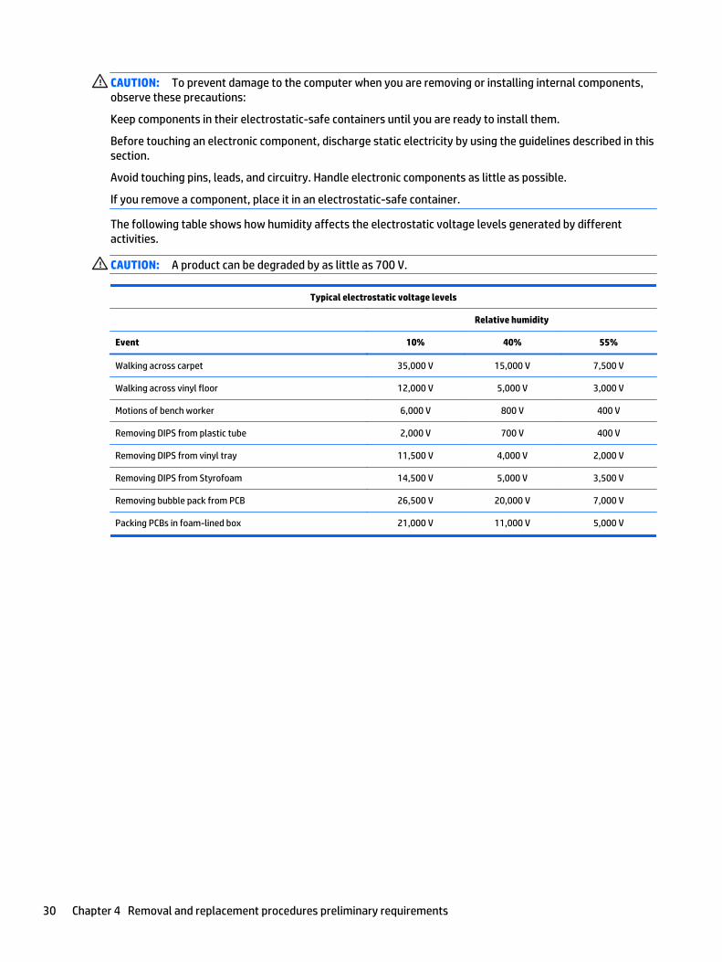
The following table shows how humidity affects the electrostatic voltage levels generated by differentactivities.
CAUTION: A product can be degraded by as little as 700 V.
Typical electrostatic voltage levels
Relative humidity
Event 10% 40% 55%
Walking across carpet 35,000 V 15,000 V 7,500 V
Walking across vinyl floor 12,000 V 5,000 V 3,000 V
Motions of bench worker 6,000 V 800 V 400 V
Removing DIPS from plastic tube 2,000 V 700 V 400 V
Removing DIPS from vinyl tray 11,500 V 4,000 V 2,000 V
Removing DIPS from Styrofoam 14,500 V 5,000 V 3,500 V
Removing bubble pack from PCB 26,500 V 20,000 V 7,000 V
Packing PCBs in foam-lined box 21,000 V 11,000 V 5,000 V
30 Chapter 4 Removal and replacement procedures preliminary requirements
Packaging and transporting guidelines
Follow these grounding guidelines when packaging and transporting equipment:
● To avoid hand contact, transport products in static-safe tubes, bags, or boxes.
● Protect ESD-sensitive parts and assemblies with conductive or approved containers or packaging.
● Keep ESD-sensitive parts in their containers until the parts arrive at static-free workstations.
● Place items on a grounded surface before removing items from their containers.
● Always be properly grounded when touching a component or assembly.
● Store reusable ESD-sensitive parts from assemblies in protective packaging or nonconductive foam.
● Use transporters and conveyors made of antistatic belts and roller bushings. Be sure that mechanizedequipment used for moving materials is wired to ground and that proper materials are selected to avoidstatic charging. When grounding is not possible, use an ionizer to dissipate electric charges.
Workstation guidelines
Follow these grounding workstation guidelines:
● Cover the workstation with approved static-shielding material.
● Use a wrist strap connected to a properly grounded work surface and use properly grounded tools andequipment.
● Use conductive field service tools, such as cutters, screw drivers, and vacuums.
● When fixtures must directly contact dissipative surfaces, use fixtures made only of static-safematerials.
● Keep the work area free of nonconductive materials, such as ordinary plastic assembly aids andStyrofoam.
● Handle ESD-sensitive components, parts, and assemblies by the case or PCM laminate. Handle theseitems only at static-free workstations.
● Avoid contact with pins, leads, or circuitry.
● Turn off power and input signals before inserting or removing connectors or test equipment.
Grounding guidelines 31
Equipment guidelines
Grounding equipment must include either a wrist strap or a foot strap at a grounded workstation.
● When seated, wear a wrist strap connected to a grounded system. Wrist straps are flexible straps with aminimum of one megohm ±10% resistance in the ground cords. To provide proper ground, wear a strapsnugly against the skin at all times. On grounded mats with banana-plug connectors, use alligator clipsto connect a wrist strap.
● When standing, use foot straps and a grounded floor mat. Foot straps (heel, toe, or boot straps) can beused at standing workstations and are compatible with most types of shoes or boots. On conductivefloors or dissipative floor mats, use foot straps on both feet with a minimum of one megohm resistancebetween the operator and ground. To be effective, the conductive must be worn in contact with theskin.
The following grounding equipment is recommended to prevent electrostatic damage:
● Antistatic tape
● Antistatic smocks, aprons, and sleeve protectors
● Conductive bins and other assembly or soldering aids
● Nonconductive foam
● Conductive tabletop workstations with ground cords of one megohm resistance
● Static-dissipative tables or floor mats with hard ties to the ground
● Field service kits
● Static awareness labels
● Material-handling packages
● Nonconductive plastic bags, tubes, or boxes
● Metal tote boxes
● Electrostatic voltage levels and protective materials
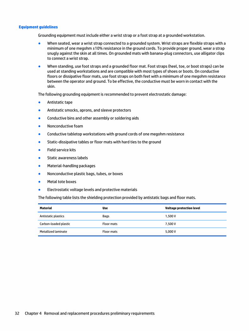
The following table lists the shielding protection provided by antistatic bags and floor mats.
Material Use Voltage protection level
Antistatic plastics Bags 1,500 V
Carbon-loaded plastic Floor mats 7,500 V
Metallized laminate Floor mats 5,000 V
32 Chapter 4 Removal and replacement procedures preliminary requirements
5 Removal and replacement procedures forCustomer Self-Repair parts
NOTE: The Customer Self-Repair program is not available in all locations. Installing a part not supported bythe Customer Self-Repair program may void your warranty. Check your warranty to determine if CustomerSelf-Repair is supported in your location.
NOTE: HP continually improves and changes product parts. For complete and current information onsupported parts for your computer, go to http://partsurfer.hp.com, select your country or region, and thenfollow the on-screen instructions.
Component replacement proceduresNOTE: Please read and follow the procedures described here to access and replace Customer Self-Repairparts successfully.
NOTE: Details about your computer, including model, serial number, product key, and length of warranty,are on the service tag at the bottom of your computer. See Service tag on page 16 for details.
This chapter provides removal and replacement procedures for Customer Self-Repair parts.
There are as many as 4 screws that must be removed, replaced, and/or loosened when servicing CustomerSelf-Repair parts. Make special note of each screw size and location during removal and replacement.
Component replacement procedures 33
Battery
Description Spare part number
6-cell, 62-Wh, 2.80-Ah, Li-ion battery 710417-001
6-cell, 47-Wh, 2.20-Ah, Li-ion battery 710416-001
Before removing the battery, follow these steps:
1. Turn off the computer. If you are unsure whether the computer is off or in Hibernation, turn thecomputer on, and then shut it down through the operating system.
2. Disconnect the power from the computer by unplugging the power cord from the computer.
3. Disconnect all external devices from the computer.
Remove the battery:
WARNING! To reduce potential safety issues, use only the user-replaceable battery provided with thecomputer, a replacement battery provided by HP, or a compatible battery purchased from HP.
CAUTION: Removing a user-replaceable battery that is the sole power source for the computer can causeloss of information. To prevent loss of information, save your work or shut down the computer throughWindows before removing the battery.
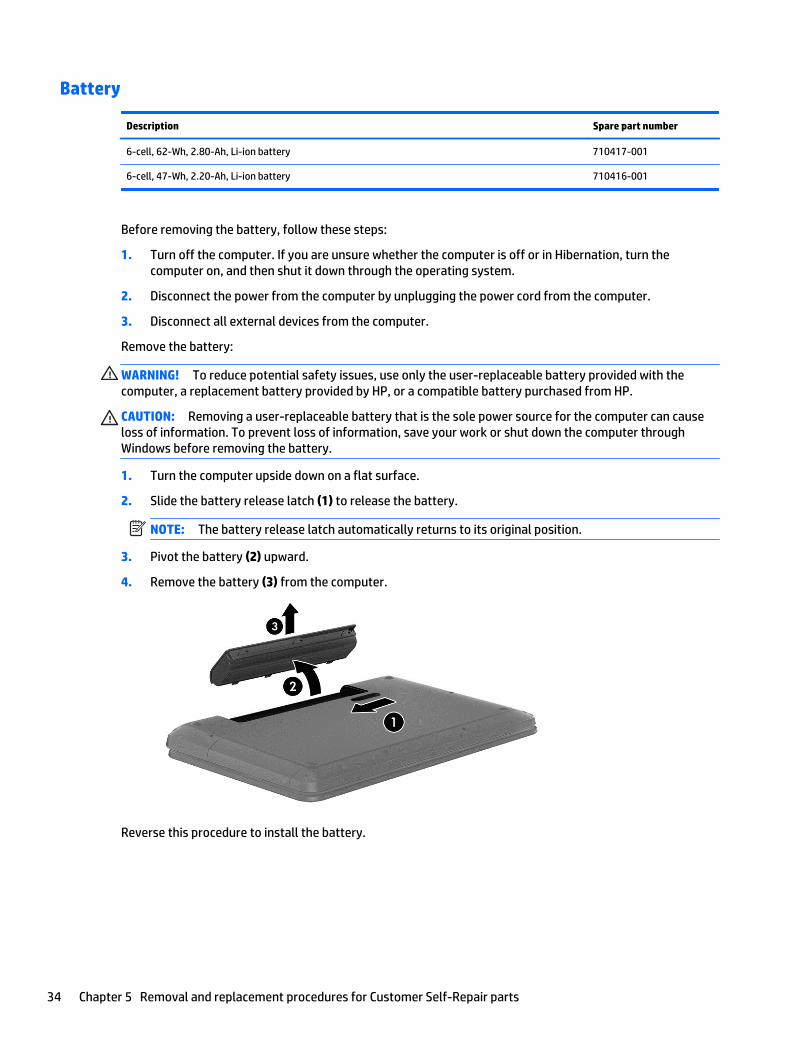
1. Turn the computer upside down on a flat surface.
2. Slide the battery release latch (1) to release the battery.
NOTE: The battery release latch automatically returns to its original position.
3. Pivot the battery (2) upward.
4. Remove the battery (3) from the computer.
Reverse this procedure to install the battery.
34 Chapter 5 Removal and replacement procedures for Customer Self-Repair parts
WLAN module
Description Spare part number
For use only on computer models equipped with an Intel processor:
Broadcom BCM43142 802.11 bgn 1x1 Wi-Fi + BT4.0 HMC Combo Adapter 753076-001
Intel Dual Band Wireless-AC 7260 802.11 ac 2×2 WiFi + BT 4.0 Combo Adapter 756753-001
Intel Dual Band Wireless-AC 3160 802.11ac 1×1 WiFi + BT 4.0 Combo Adapter 710662-001
Ralink RT3290LE 802.11b/g/n 1×1 WiFi and Bluetooth 4.0 Combo Adapter 690020-001
Realtek RTL8188EE 802.11bgn Wi-Fi Adapter 709848-001
Intel Dual Band Wireless-AC 3160 802.11 ac 1x1 WiFi + BT 4.0 Combo Adapter 784638-001
Intel Dual Band Wireless-AC 7260 802.11AC 2x2+ BT 4.0 Combo Adapter 784650-001
CAUTION: To prevent an unresponsive system, replace the wireless module only with a wireless moduleauthorized for use in the computer by the governmental agency that regulates wireless devices in yourcountry or region. If you replace the module and then receive a warning message, remove the module torestore device functionality, and then contact technical support.
Before removing the WLAN module, follow these steps:
1. Turn off the computer. If you are unsure whether the computer is off or in Hibernation, turn thecomputer on, and then shut it down through the operating system.
2. Disconnect the power from the computer by unplugging the power cord from the computer.
3. Disconnect all external devices from the computer.
4. Remove the battery (see Battery on page 34).
Remove the WLAN module:
1. Close the computer.
2. Turn the computer upside down with the front toward you.
3. Loosen the Phillips PM2.5×5.0 captive screw (1) that secures the service cover to the computer.
4. Lift the back edge of the service cover (2) until it detaches from the computer.
Component replacement procedures 35
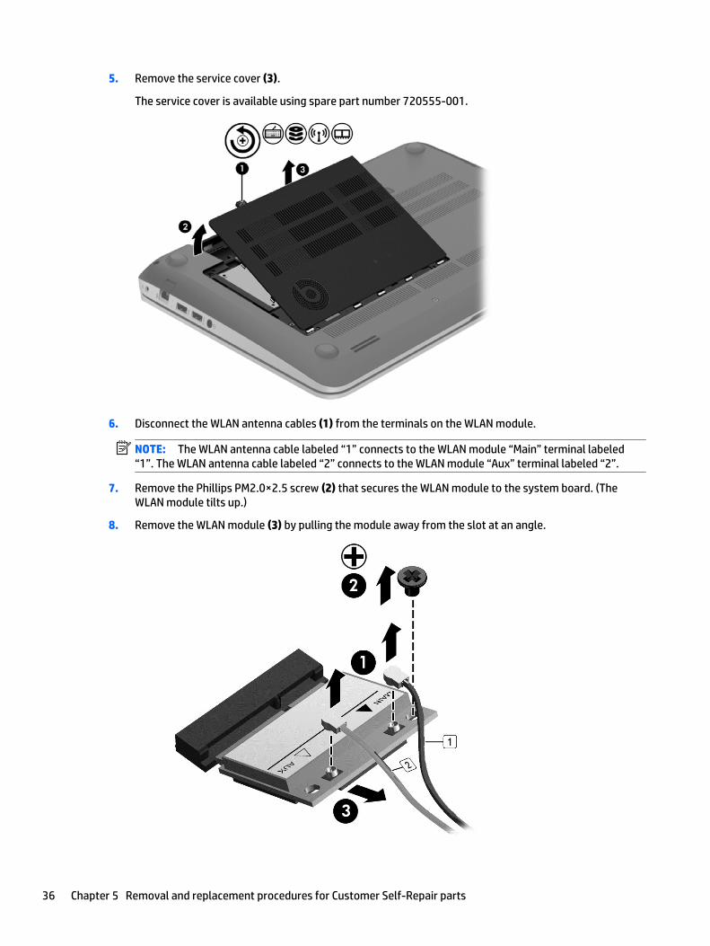
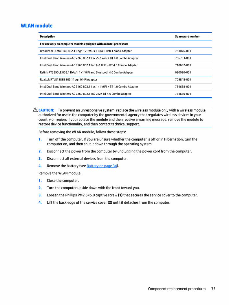
5. Remove the service cover (3).
The service cover is available using spare part number 720555-001.
6. Disconnect the WLAN antenna cables (1) from the terminals on the WLAN module.
NOTE: The WLAN antenna cable labeled “1” connects to the WLAN module “Main” terminal labeled“1”. The WLAN antenna cable labeled “2” connects to the WLAN module “Aux” terminal labeled “2”.
7. Remove the Phillips PM2.0×2.5 screw (2) that secures the WLAN module to the system board. (TheWLAN module tilts up.)
8. Remove the WLAN module (3) by pulling the module away from the slot at an angle.
36 Chapter 5 Removal and replacement procedures for Customer Self-Repair parts
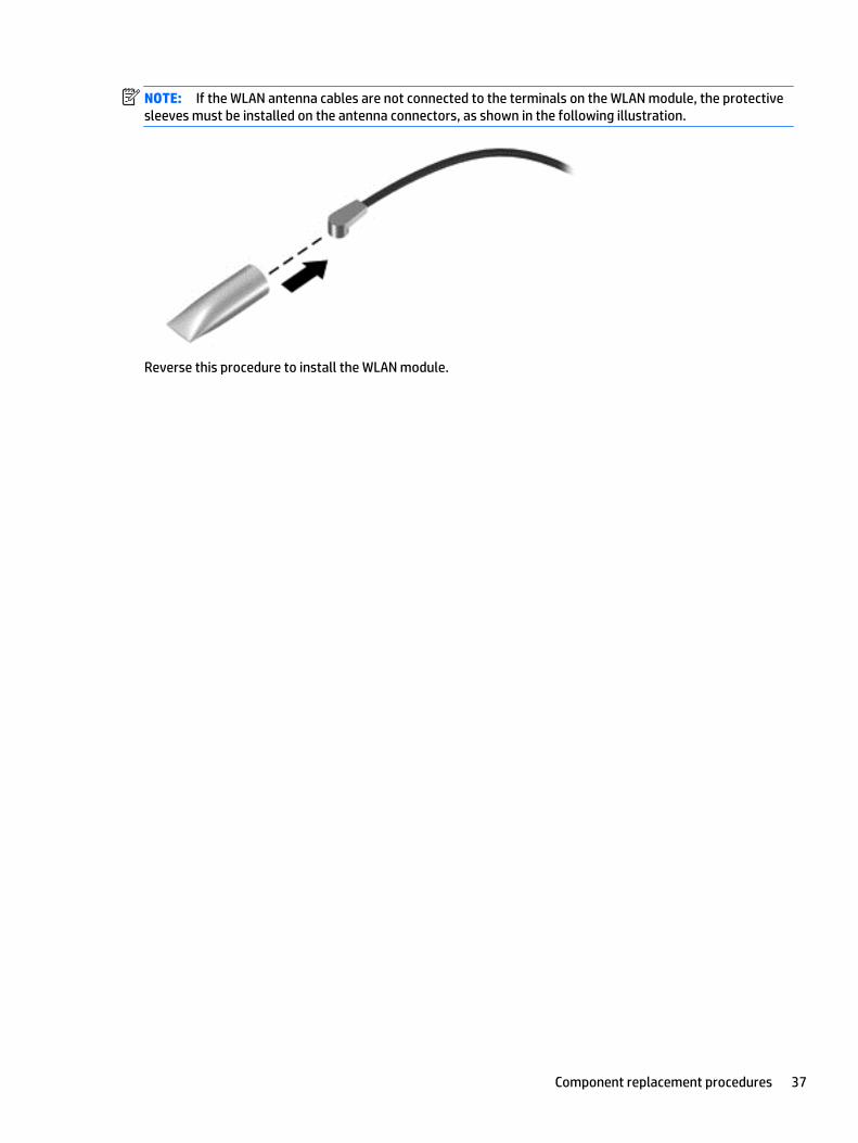
NOTE: If the WLAN antenna cables are not connected to the terminals on the WLAN module, the protectivesleeves must be installed on the antenna connectors, as shown in the following illustration.
Reverse this procedure to install the WLAN module.
Component replacement procedures 37
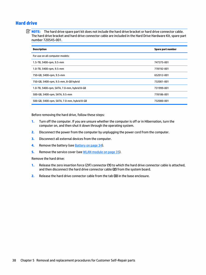
Hard drive
NOTE: The hard drive spare part kit does not include the hard drive bracket or hard drive connector cable.The hard drive bracket and hard drive connector cable are included in the Hard Drive Hardware Kit, spare partnumber 720545-001.
Description Spare part number
For use on all computer models:
1.5-TB, 5400-rpm, 9.5-mm 747375-001
1.0-TB, 5400-rpm, 9.5-mm 778192-001
750-GB, 5400-rpm, 9.5-mm 652012-001
750-GB, 5400-rpm, 9.5-mm, 8-GB hybrid 732001-001
1.0-TB, 5400-rpm, SATA, 7.0-mm, hybrid 8-GB 731999-001
500-GB, 5400-rpm, SATA, 9.5-mm 778186-001
500-GB, 5400-rpm, SATA, 7.0-mm, hybrid 8-GB 732000-001
Before removing the hard drive, follow these steps:
1. Turn off the computer. If you are unsure whether the computer is off or in Hibernation, turn thecomputer on, and then shut it down through the operating system.
2. Disconnect the power from the computer by unplugging the power cord from the computer.
3. Disconnect all external devices from the computer.
4. Remove the battery (see Battery on page 34).
5. Remove the service cover (see WLAN module on page 35).
Remove the hard drive:
1. Release the zero insertion force (ZIF) connector (1) to which the hard drive connector cable is attached,and then disconnect the hard drive connector cable (2) from the system board.
2. Release the hard drive connector cable from the tab (3) in the base enclosure.
38 Chapter 5 Removal and replacement procedures for Customer Self-Repair parts
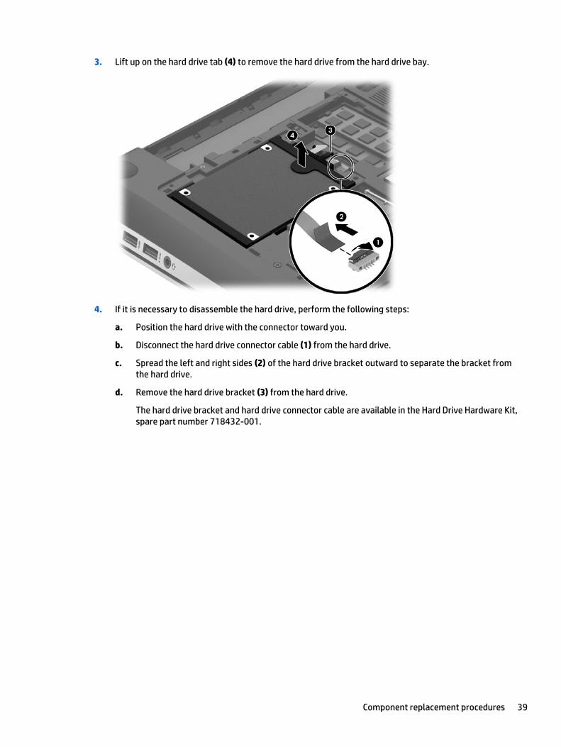
3. Lift up on the hard drive tab (4) to remove the hard drive from the hard drive bay.
4. If it is necessary to disassemble the hard drive, perform the following steps:
a. Position the hard drive with the connector toward you.
b. Disconnect the hard drive connector cable (1) from the hard drive.
c. Spread the left and right sides (2) of the hard drive bracket outward to separate the bracket fromthe hard drive.
d. Remove the hard drive bracket (3) from the hard drive.
The hard drive bracket and hard drive connector cable are available in the Hard Drive Hardware Kit,spare part number 718432-001.
Component replacement procedures 39
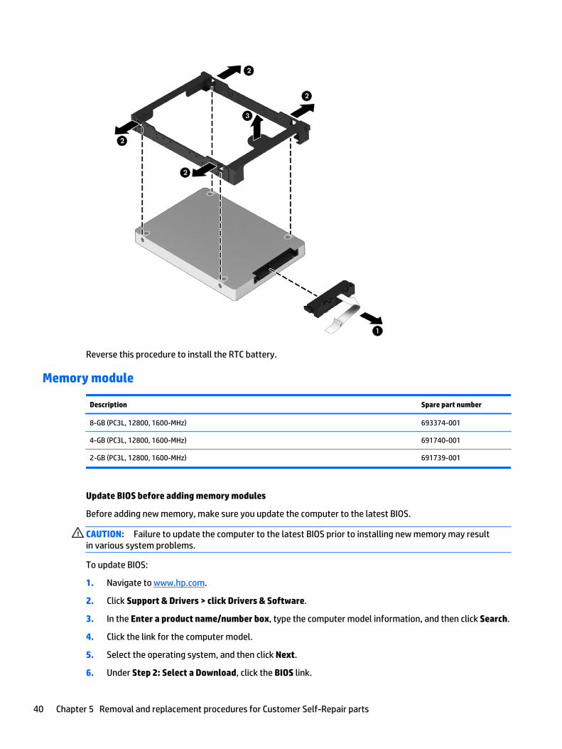
Reverse this procedure to install the RTC battery.
Memory module
Description Spare part number
8-GB (PC3L, 12800, 1600-MHz) 693374-001
4-GB (PC3L, 12800, 1600-MHz) 691740-001
2-GB (PC3L, 12800, 1600-MHz) 691739-001
Update BIOS before adding memory modules
Before adding new memory, make sure you update the computer to the latest BIOS.
CAUTION: Failure to update the computer to the latest BIOS prior to installing new memory may resultin various system problems.
To update BIOS:
1. Navigate to www.hp.com.
2. Click Support & Drivers > click Drivers & Software.
3. In the Enter a product name/number box, type the computer model information, and then click Search.
4. Click the link for the computer model.
5. Select the operating system, and then click Next.
6. Under Step 2: Select a Download, click the BIOS link.
40 Chapter 5 Removal and replacement procedures for Customer Self-Repair parts
7. Click the link for the most recent BIOS.
8. Click the Download button, and then follow the on-screen instructions.
Before removing a memory module, follow these steps:
1. Turn off the computer. If you are unsure whether the computer is off or in Hibernation, turn thecomputer on, and then shut it down through the operating system.
2. Disconnect the power from the computer by unplugging the power cord from the computer.
3. Disconnect all external devices from the computer.
4. Remove the battery (see Battery on page 34).
5. Remove the service cover (see WLAN module on page 35).
Remove the memory module:
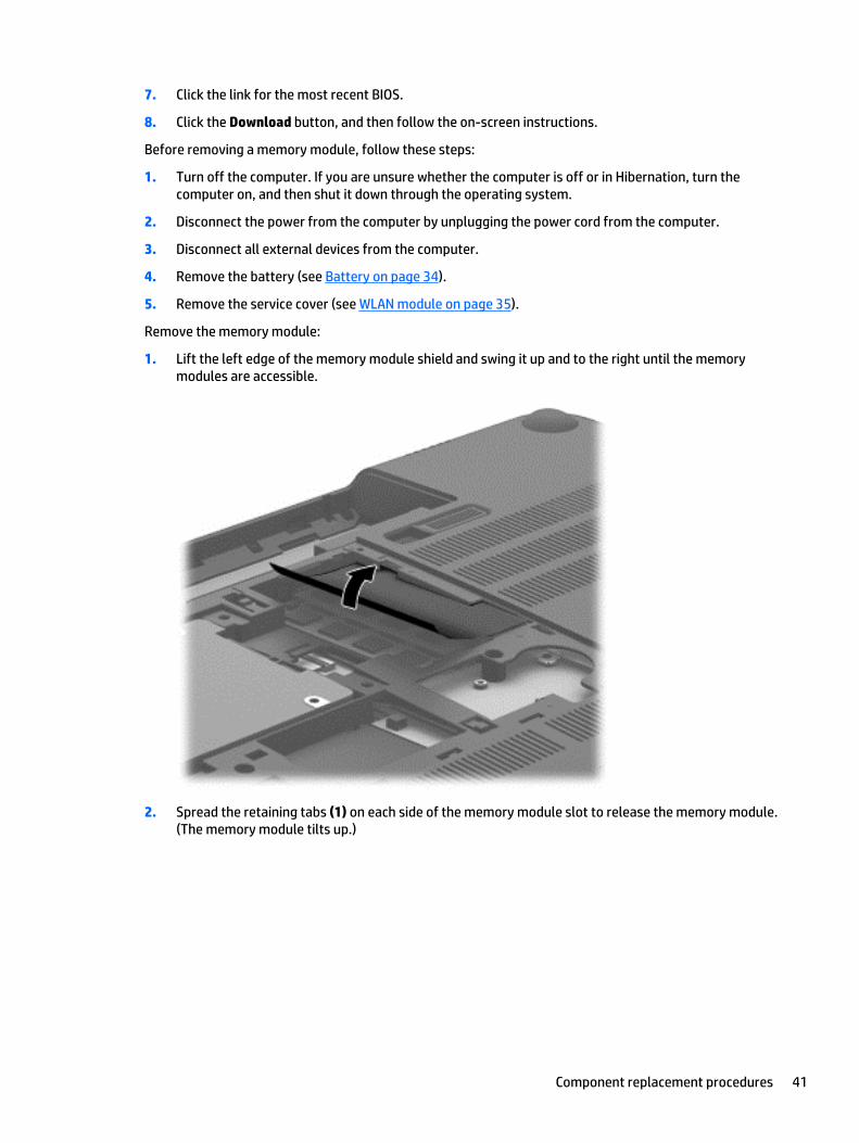
1. Lift the left edge of the memory module shield and swing it up and to the right until the memorymodules are accessible.
2. Spread the retaining tabs (1) on each side of the memory module slot to release the memory module.(The memory module tilts up.)
Component replacement procedures 41
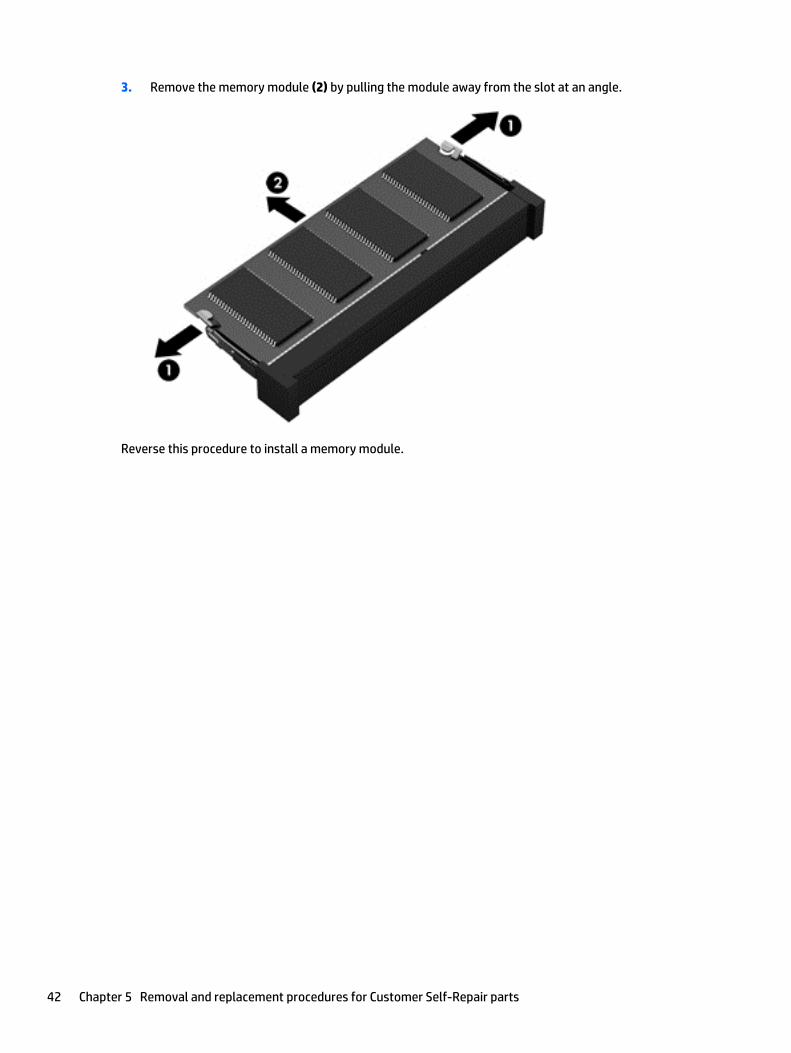
3. Remove the memory module (2) by pulling the module away from the slot at an angle.
Reverse this procedure to install a memory module.
42 Chapter 5 Removal and replacement procedures for Customer Self-Repair parts
6 Removal and replacement procedures forAuthorized Service Provider parts
CAUTION: Components described in this chapter should only be accessed by an authorized service provider.Accessing these parts can damage the computer or void the warranty.
NOTE: HP continually improves and changes product parts. For complete and current information onsupported parts for your computer, go to http://partsurfer.hp.com, select your country or region, and thenfollow the on-screen instructions.
Component replacement proceduresThis chapter provides removal and replacement procedures for Authorized Service Provider only parts.
There are as many as 94 screws that must be removed, replaced, and/or loosened when servicing thecomputer. Make special note of each screw size and location during removal and replacement.
RTC battery
Description Spare part number
RTC battery 718440-001
Before removing the RTC battery, follow these steps:
1. Turn off the computer. If you are unsure whether the computer is off or in Hibernation, turn thecomputer on, and then shut it down through the operating system.
2. Disconnect the power from the computer by unplugging the power cord from the computer.
3. Disconnect all external devices from the computer.
4. Remove the battery (see Battery on page 34).
5. Remove the service cover (see WLAN module on page 35).
Remove the RTC battery:
▲ Use a thin, non-conductive tool (1) to remove the disc cell RTC battery (2) from the socket on thesystem board.
Component replacement procedures 43
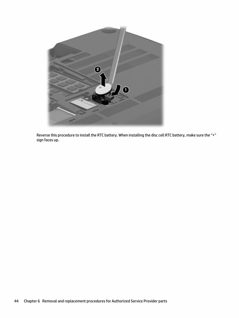
Reverse this procedure to install the RTC battery. When installing the disc cell RTC battery, make sure the “+”sign faces up.
44 Chapter 6 Removal and replacement procedures for Authorized Service Provider parts
Base enclosure
Description Spare part number
Base enclosure; includes red Beats logo 760035-001
Base enclosure; includes grey Beats logo 774152-001
Before removing the base enclosure, follow these steps:
1. Turn off the computer. If you are unsure whether the computer is off or in Hibernation, turn thecomputer on, and then shut it down through the operating system.
2. Disconnect the power from the computer by unplugging the power cord from the computer.
3. Disconnect all external devices from the computer.
4. Remove the battery (see Battery on page 34).
5. Remove the solid-state drive (see WLAN module on page 35).
6. Remove the hard drive (see Hard drive on page 38).
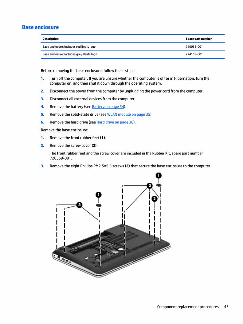
Remove the base enclosure:
1. Remove the front rubber feet (1).
2. Remove the screw cover (2).
The front rubber feet and the screw cover are included in the Rubber Kit, spare part number720559-001.
3. Remove the eight Phillips PM2.5×5.5 screws (2) that secure the base enclosure to the computer.
Component replacement procedures 45
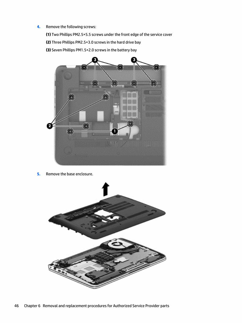
4. Remove the following screws:
(1) Two Phillips PM2.5×5.5 screws under the front edge of the service cover
(2) Three Phillips PM2.5×3.0 screws in the hard drive bay
(3) Seven Phillips PM1.5×2.0 screws in the battery bay
5. Remove the base enclosure.
46 Chapter 6 Removal and replacement procedures for Authorized Service Provider parts
Reverse this procedure to install the base enclosure.
Display assembly
Description Spare part number
15.6-in, AntiGlare, FHD, LED, TouchScreen display assembly for use on all computer models 788475-001
15.6-in, AntiGlare, HD, LED, TouchScreen display assembly for use on all computer models 788474-001
15.6-in, BrightView, FHD, LED, non-TouchScreen display assembly for use only on computer modelsequipped with an Intel processor
720552-001
15.6-in, BrightView, HD, LED, non-TouchScreen display assembly for use only on computer modelsequipped with an Intel processor
720551-001
To remove the display assembly and access the display assembly subcomponents, follow these steps:
1. Turn off the computer. If you are unsure whether the computer is off or in Hibernation, turn thecomputer on, and then shut it down through the operating system.
2. Disconnect the power from the computer by unplugging the power cord from the computer.
3. Disconnect all external devices from the computer.
4. Remove the battery (see Battery on page 34).
5. Disconnect the wireless antenna cables from the WLAN module (see WLAN module on page 35).
6. Remove the hard drive (see Hard drive on page 38).
7. Remove the base enclosure (see Base enclosure on page 45).
Remove the display assembly:
1. Release the wireless antenna cables from the retention clips built into the left rear speaker (1),connector board (2), and top cover (3).
2. Release the wireless antenna cables from the retention clips (4) built into the subwoofer.
3. Release the ZIF connector to which the display panel cable is attached, and then disconnect the displaypanel cable (5) from the system board.
4. Disconnect the the webcam/microphone module cable (6) from the system board.
Component replacement procedures 47
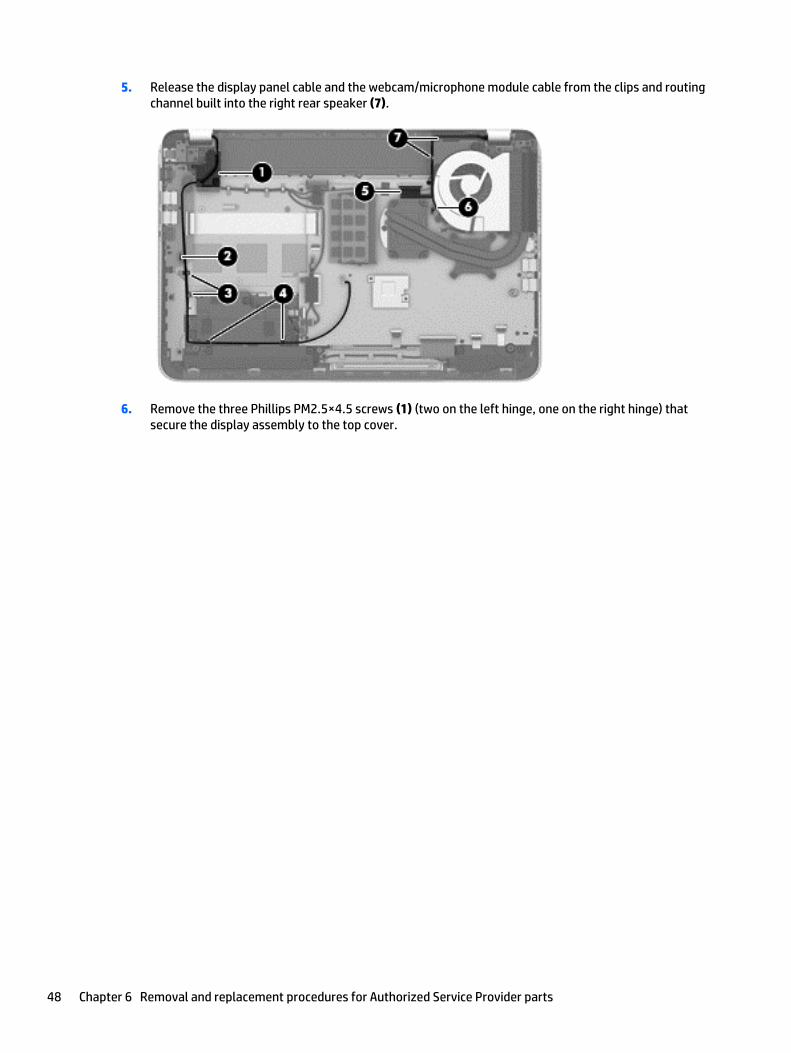
5. Release the display panel cable and the webcam/microphone module cable from the clips and routingchannel built into the right rear speaker (7).
6. Remove the three Phillips PM2.5×4.5 screws (1) (two on the left hinge, one on the right hinge) thatsecure the display assembly to the top cover.
48 Chapter 6 Removal and replacement procedures for Authorized Service Provider parts
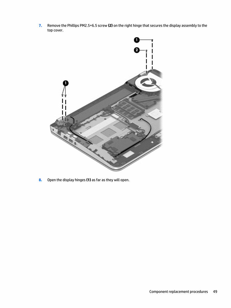
7. Remove the Phillips PM2.5×6.5 screw (2) on the right hinge that secures the display assembly to thetop cover.
8. Open the display hinges (1) as far as they will open.
Component replacement procedures 49
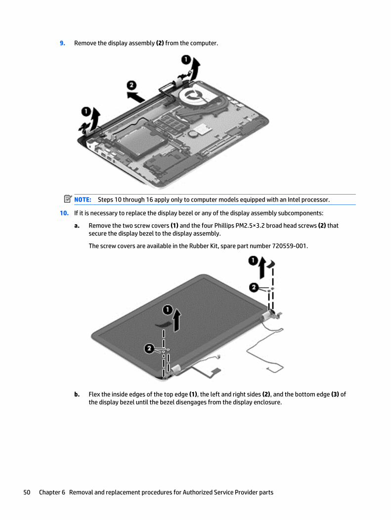
9. Remove the display assembly (2) from the computer.
NOTE: Steps 10 through 16 apply only to computer models equipped with an Intel processor.
10. If it is necessary to replace the display bezel or any of the display assembly subcomponents:
a. Remove the two screw covers (1) and the four Phillips PM2.5×3.2 broad head screws (2) thatsecure the display bezel to the display assembly.
The screw covers are available in the Rubber Kit, spare part number 720559-001.
b. Flex the inside edges of the top edge (1), the left and right sides (2), and the bottom edge (3) ofthe display bezel until the bezel disengages from the display enclosure.
50 Chapter 6 Removal and replacement procedures for Authorized Service Provider parts
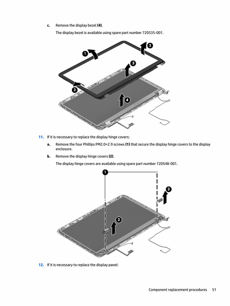
c. Remove the display bezel (4).
The display bezel is available using spare part number 720535-001.
11. If it is necessary to replace the display hinge covers:
a. Remove the four Phillips PM2.0×2.9 screws (1) that secure the display hinge covers to the displayenclosure.
b. Remove the display hinge covers (2).
The display hinge covers are available using spare part number 720548-001.
12. If it is necessary to replace the display panel:
Component replacement procedures 51
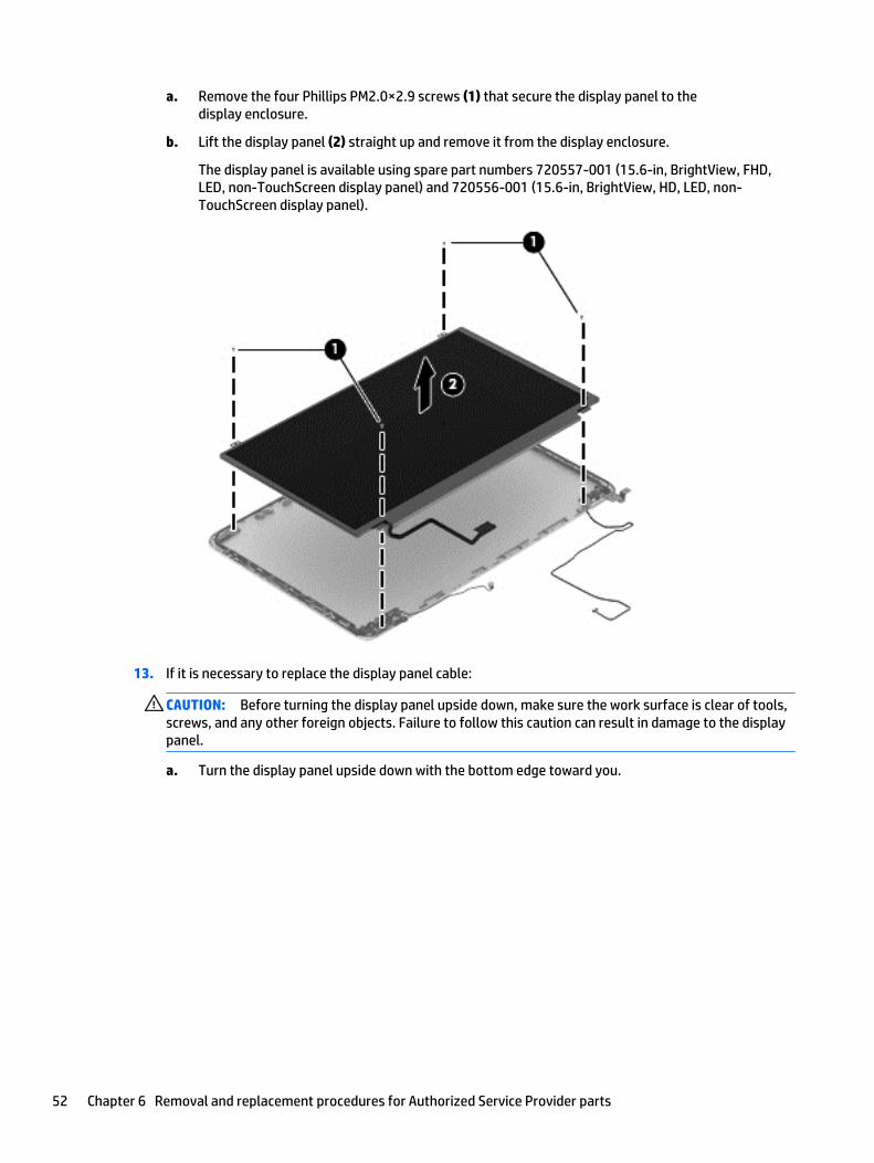
a. Remove the four Phillips PM2.0×2.9 screws (1) that secure the display panel to thedisplay enclosure.
b. Lift the display panel (2) straight up and remove it from the display enclosure.
The display panel is available using spare part numbers 720557-001 (15.6-in, BrightView, FHD,LED, non-TouchScreen display panel) and 720556-001 (15.6-in, BrightView, HD, LED, non-TouchScreen display panel).
13. If it is necessary to replace the display panel cable:
CAUTION: Before turning the display panel upside down, make sure the work surface is clear of tools,screws, and any other foreign objects. Failure to follow this caution can result in damage to the displaypanel.
a. Turn the display panel upside down with the bottom edge toward you.
52 Chapter 6 Removal and replacement procedures for Authorized Service Provider parts
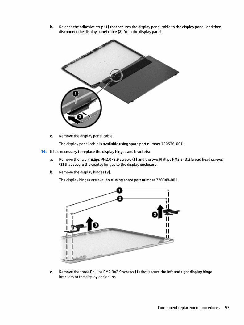
b. Release the adhesive strip (1) that secures the display panel cable to the display panel, and thendisconnect the display panel cable (2) from the display panel.
c. Remove the display panel cable.
The display panel cable is available using spare part number 720536-001.
14. If it is necessary to replace the display hinges and brackets:
a. Remove the two Phillips PM2.0×2.9 screws (1) and the two Phillips PM2.5×3.2 broad head screws(2) that secure the display hinges to the display enclosure.
b. Remove the display hinges (3).
The display hinges are available using spare part number 720548-001.
c. Remove the three Phillips PM2.0×2.9 screws (1) that secure the left and right display hingebrackets to the display enclosure.
Component replacement procedures 53
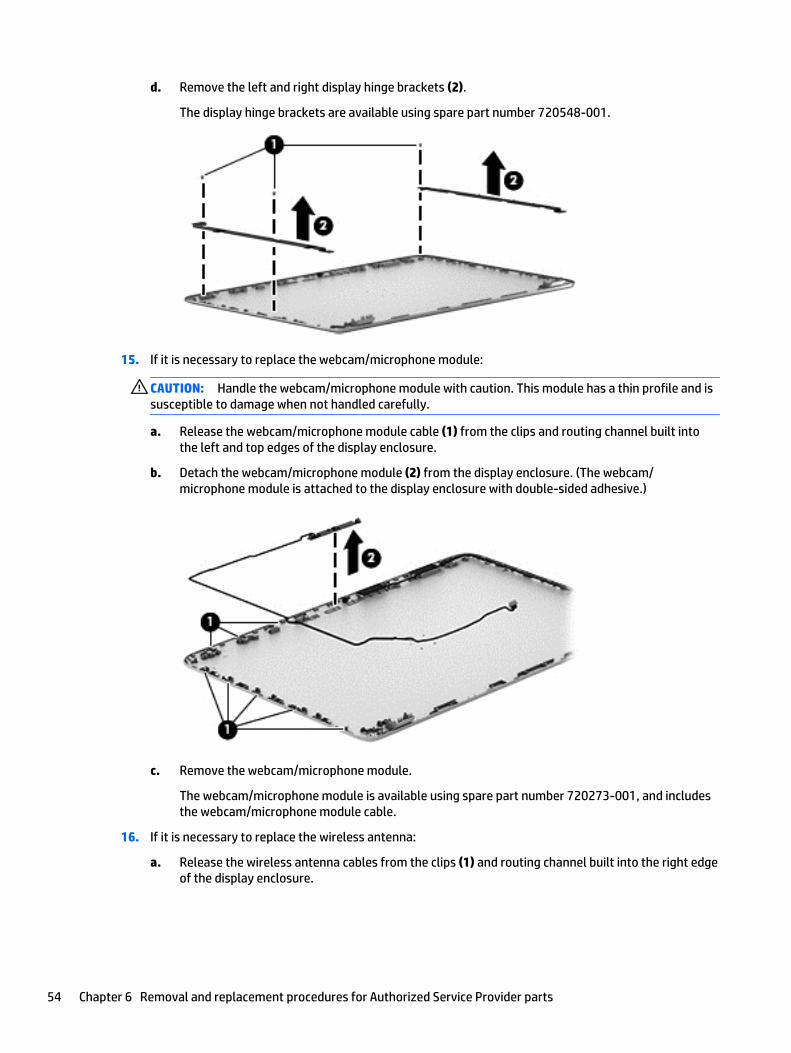
d. Remove the left and right display hinge brackets (2).
The display hinge brackets are available using spare part number 720548-001.
15. If it is necessary to replace the webcam/microphone module:
CAUTION: Handle the webcam/microphone module with caution. This module has a thin profile and issusceptible to damage when not handled carefully.
a. Release the webcam/microphone module cable (1) from the clips and routing channel built intothe left and top edges of the display enclosure.
b. Detach the webcam/microphone module (2) from the display enclosure. (The webcam/microphone module is attached to the display enclosure with double-sided adhesive.)
c. Remove the webcam/microphone module.
The webcam/microphone module is available using spare part number 720273-001, and includesthe webcam/microphone module cable.
16. If it is necessary to replace the wireless antenna:
a. Release the wireless antenna cables from the clips (1) and routing channel built into the right edgeof the display enclosure.
54 Chapter 6 Removal and replacement procedures for Authorized Service Provider parts
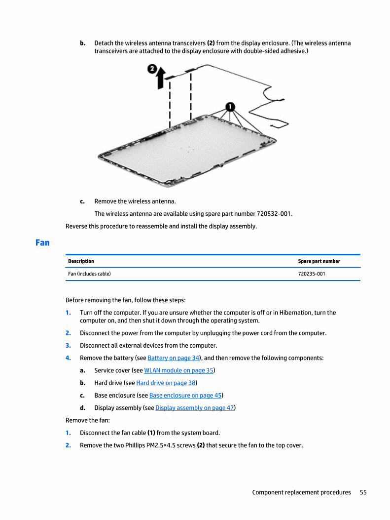
b. Detach the wireless antenna transceivers (2) from the display enclosure. (The wireless antennatransceivers are attached to the display enclosure with double-sided adhesive.)
c. Remove the wireless antenna.
The wireless antenna are available using spare part number 720532-001.
Reverse this procedure to reassemble and install the display assembly.
Fan
Description Spare part number
Fan (includes cable) 720235-001
Before removing the fan, follow these steps:
1. Turn off the computer. If you are unsure whether the computer is off or in Hibernation, turn thecomputer on, and then shut it down through the operating system.
2. Disconnect the power from the computer by unplugging the power cord from the computer.
3. Disconnect all external devices from the computer.
4. Remove the battery (see Battery on page 34), and then remove the following components:
a. Service cover (see WLAN module on page 35)
b. Hard drive (see Hard drive on page 38)
c. Base enclosure (see Base enclosure on page 45)
d. Display assembly (see Display assembly on page 47)
Remove the fan:
1. Disconnect the fan cable (1) from the system board.
2. Remove the two Phillips PM2.5×4.5 screws (2) that secure the fan to the top cover.
Component replacement procedures 55
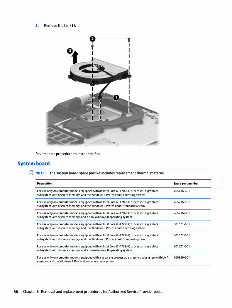
3. Remove the fan (3).
Reverse this procedure to install the fan.
System board
NOTE: The system board spare part kit includes replacement thermal material.
Description Spare part number
For use only on computer models equipped with an Intel Core i7-4702HQ processor, a graphicssubsystem with discrete memory, and the Windows 8 Professional operating system
765736-601
For use only on computer models equipped with an Intel Core i7-4702HQ processor, a graphicssubsystem with discrete memory, and the Windows 8 Professional Standard system
765736-501
For use only on computer models equipped with an Intel Core i7-4702HQ processor, a graphicssubsystem with discrete memory, and a non-Windows 8 operating system
765736-001
For use only on computer models equipped with an Intel Core i7-4722HQ processor, a graphicssubsystem with discrete memory, and the Windows 8 Professional operating system
801521-601
For use only on computer models equipped with an Intel Core i7-4722HQ processor, a graphicssubsystem with discrete memory, and the Windows 8 Professional Standard system
801521-501
For use only on computer models equipped with an Intel Core i7-4722HQ processor, a graphicssubsystem with discrete memory, and a non-Windows 8 operating system
801521-001
For use only on computer models equipped with a separate processor, a graphics subsystem with UMAmemory, and the Windows 8 Professional operating system
760289-601
56 Chapter 6 Removal and replacement procedures for Authorized Service Provider parts
Description Spare part number
For use only on computer models equipped with a separate processor, a graphics subsystem with UMAmemory, and the Windows 8 Standard operating system
760289-501
For use only on computer models equipped with a separate processor, a graphics subsystem with UMAmemory, and a non-Windows 8 operating system
760289-001
Before removing the system board, follow these steps:
1. Turn off the computer. If you are unsure whether the computer is off or in Hibernation, turn thecomputer on, and then shut it down through the operating system.
2. Disconnect the power from the computer by unplugging the power cord from the computer.
3. Disconnect all external devices from the computer.
4. Remove the battery (see Battery on page 34), and then remove the following components:
a. Service cover (see WLAN module on page 35)
b. Hard drive (see Hard drive on page 38)
c. Base enclosure (see Base enclosure on page 45)
d. Display assembly (see Display assembly on page 47)
e. Fan (see Fan on page 55)
NOTE: When replacing the system board, be sure that the following components are removed from thedefective system board and installed on the replacement system board:
● Memory module (see Memory module on page 40)
● Heat sink (see Heat sink on page 60)
● Processor (see Processor on page 62)
Remove the system board:
1. Disconnect the following cables from the system board:
(1) Connector board cable
(2) Connector board ribbon cable
(3) Power connector cable
(4) Display panel cable
(5) Webcam/microphone module cable
(6) Wireless antenna cables
Component replacement procedures 57
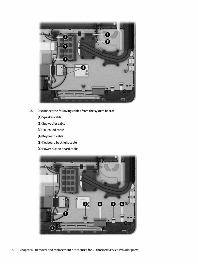
2. Disconnect the following cables from the system board:
(1) Speaker cable
(2) Subwoofer cable
(3) TouchPad cable
(4) Keyboard cable
(5) Keyboard backlight cable
(6) Power button board cable
58 Chapter 6 Removal and replacement procedures for Authorized Service Provider parts
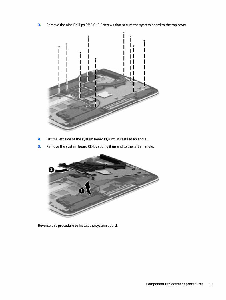
3. Remove the nine Phillips PM2.0×2.9 screws that secure the system board to the top cover.
4. Lift the left side of the system board (1) until it rests at an angle.
5. Remove the system board (2) by sliding it up and to the left an angle.
Reverse this procedure to install the system board.
Component replacement procedures 59
Heat sink
NOTE: The heat sink spare part kit includes replacement thermal material.
Description Spare part number
For use only on computer models equipped with an Intel processor and a graphics subsystem withdiscrete memory
765737-001
For use only on computer models equipped with an Intel processor and a graphics subsystem with UMAmemory
720541-001
Before removing the heat sink, follow these steps:
1. Turn off the computer. If you are unsure whether the computer is off or in Hibernation, turn thecomputer on, and then shut it down through the operating system.
2. Disconnect the power from the computer by unplugging the power cord from the computer.
3. Disconnect all external devices from the computer.
4. Remove the battery (see Battery on page 34), and then remove the following components:
a. Service cover (see WLAN module on page 35)
b. Hard drive (see Hard drive on page 38)
c. Base enclosure (see Base enclosure on page 45)
d. Display assembly (see Display assembly on page 47)
e. Fan (see Fan on page 55)
f. System board (see System board on page 56)
Remove the heat sink:
1. Turn the system board upside down, with the front toward you.
2. Following the 1 through 4 sequence stamped into the heat sink, loosen the four Phillips PM2.0×11.0captive screws (1) that secure the heat sink to the system board.
60 Chapter 6 Removal and replacement procedures for Authorized Service Provider parts
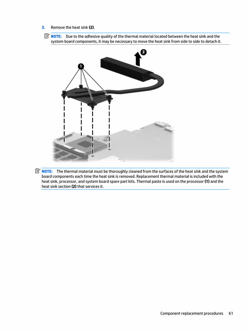
3. Remove the heat sink (2).
NOTE: Due to the adhesive quality of the thermal material located between the heat sink and thesystem board components, it may be necessary to move the heat sink from side to side to detach it.
NOTE: The thermal material must be thoroughly cleaned from the surfaces of the heat sink and the systemboard components each time the heat sink is removed. Replacement thermal material is included with theheat sink, processor, and system board spare part kits. Thermal paste is used on the processor (1) and theheat sink section (2) that services it.
Component replacement procedures 61
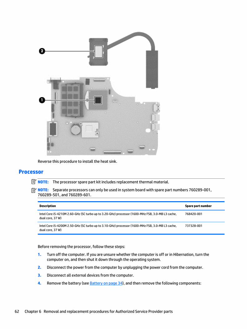
Reverse this procedure to install the heat sink.
Processor
NOTE: The processor spare part kit includes replacement thermal material.
NOTE: Separate processors can only be used in system board with spare part numbers 760289-001,760289-501, and 760289-601.
Description Spare part number
Intel Core i5-4210M 2.60-GHz (SC turbo up to 3.20-GHz) processor (1600-MHz FSB, 3.0-MB L3 cache,dual core, 37 W)
768420-001
Intel Core i5-4200M 2.50-GHz (SC turbo up to 3.10-GHz) processor (1600-MHz FSB, 3.0-MB L3 cache,dual core, 37 W)
737328-001
Before removing the processor, follow these steps:
1. Turn off the computer. If you are unsure whether the computer is off or in Hibernation, turn thecomputer on, and then shut it down through the operating system.
2. Disconnect the power from the computer by unplugging the power cord from the computer.
3. Disconnect all external devices from the computer.
4. Remove the battery (see Battery on page 34), and then remove the following components:
62 Chapter 6 Removal and replacement procedures for Authorized Service Provider parts
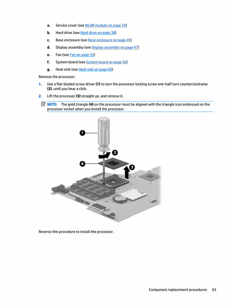
a. Service cover (see WLAN module on page 35)
b. Hard drive (see Hard drive on page 38)
c. Base enclosure (see Base enclosure on page 45)
d. Display assembly (see Display assembly on page 47)
e. Fan (see Fan on page 55)
f. System board (see System board on page 56)
g. Heat sink (see Heat sink on page 60)
Remove the processor:
1. Use a flat-bladed screw driver (1) to turn the processor locking screw one-half turn counterclockwise(2), until you hear a click.
2. Lift the processor (3) straight up, and remove it.
NOTE: The gold triangle (4) on the processor must be aligned with the triangle icon embossed on theprocessor socket when you install the processor.
Reverse this procedure to install the processor.
Component replacement procedures 63
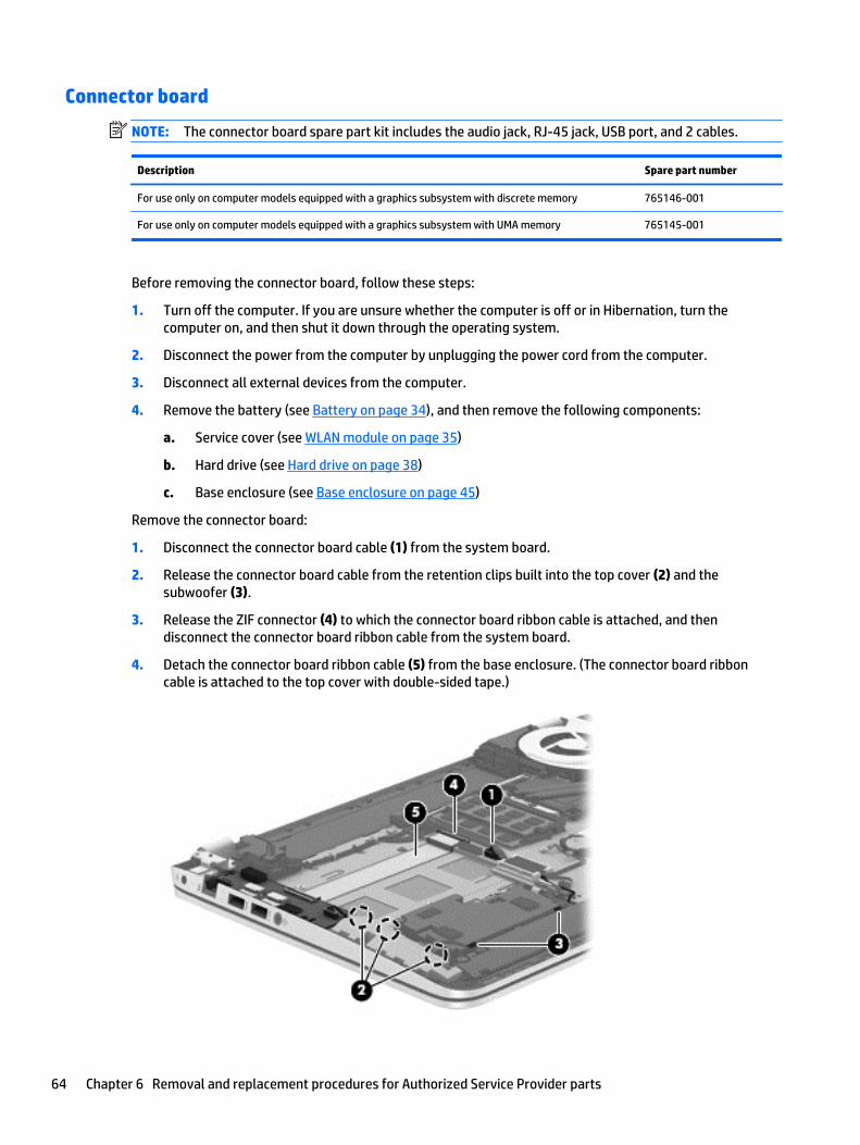
Connector board
NOTE: The connector board spare part kit includes the audio jack, RJ-45 jack, USB port, and 2 cables.
Description Spare part number
For use only on computer models equipped with a graphics subsystem with discrete memory 765146-001
For use only on computer models equipped with a graphics subsystem with UMA memory 765145-001
Before removing the connector board, follow these steps:
1. Turn off the computer. If you are unsure whether the computer is off or in Hibernation, turn thecomputer on, and then shut it down through the operating system.
2. Disconnect the power from the computer by unplugging the power cord from the computer.
3. Disconnect all external devices from the computer.
4. Remove the battery (see Battery on page 34), and then remove the following components:
a. Service cover (see WLAN module on page 35)
b. Hard drive (see Hard drive on page 38)
c. Base enclosure (see Base enclosure on page 45)
Remove the connector board:
1. Disconnect the connector board cable (1) from the system board.
2. Release the connector board cable from the retention clips built into the top cover (2) and thesubwoofer (3).
3. Release the ZIF connector (4) to which the connector board ribbon cable is attached, and thendisconnect the connector board ribbon cable from the system board.
4. Detach the connector board ribbon cable (5) from the base enclosure. (The connector board ribboncable is attached to the top cover with double-sided tape.)
64 Chapter 6 Removal and replacement procedures for Authorized Service Provider parts
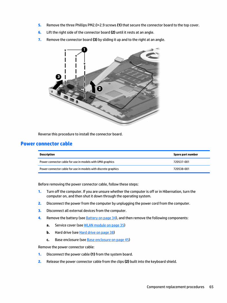
5. Remove the three Phillips PM2.0×2.9 screws (1) that secure the connector board to the top cover.
6. Lift the right side of the connector board (2) until it rests at an angle.
7. Remove the connector board (3) by sliding it up and to the right at an angle.
Reverse this procedure to install the connector board.
Power connector cable
Description Spare part number
Power connector cable for use in models with UMA graphics 720537-001
Power connector cable for use in models with discrete graphics 720538-001
Before removing the power connector cable, follow these steps:
1. Turn off the computer. If you are unsure whether the computer is off or in Hibernation, turn thecomputer on, and then shut it down through the operating system.
2. Disconnect the power from the computer by unplugging the power cord from the computer.
3. Disconnect all external devices from the computer.
4. Remove the battery (see Battery on page 34), and then remove the following components:
a. Service cover (see WLAN module on page 35)
b. Hard drive (see Hard drive on page 38)
c. Base enclosure (see Base enclosure on page 45)
Remove the power connector cable:
1. Disconnect the power cable (1) from the system board.
2. Release the power connector cable from the clips (2) built into the keyboard shield.
Component replacement procedures 65
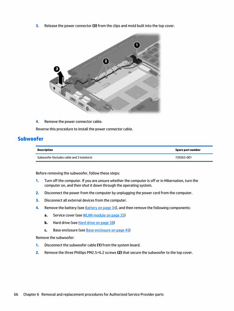
3. Release the power connector (3) from the clips and mold built into the top cover.
4. Remove the power connector cable.
Reverse this procedure to install the power connector cable.
Subwoofer
Description Spare part number
Subwoofer (includes cable and 3 isolators) 720563-001
Before removing the subwoofer, follow these steps:
1. Turn off the computer. If you are unsure whether the computer is off or in Hibernation, turn thecomputer on, and then shut it down through the operating system.
2. Disconnect the power from the computer by unplugging the power cord from the computer.
3. Disconnect all external devices from the computer.
4. Remove the battery (see Battery on page 34), and then remove the following components:
a. Service cover (see WLAN module on page 35)
b. Hard drive (see Hard drive on page 38)
c. Base enclosure (see Base enclosure on page 45)
Remove the subwoofer:
1. Disconnect the subwoofer cable (1) from the system board.
2. Remove the three Phillips PM2.5×6.2 screws (2) that secure the subwoofer to the top cover.
66 Chapter 6 Removal and replacement procedures for Authorized Service Provider parts
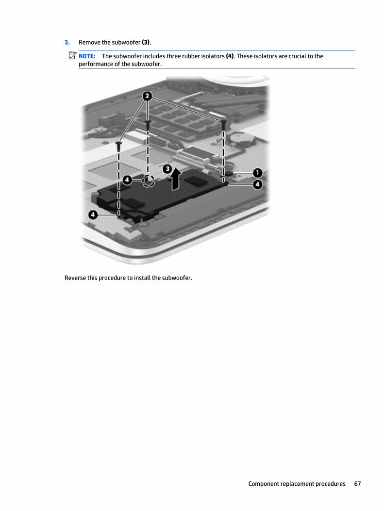
3. Remove the subwoofer (3).
NOTE: The subwoofer includes three rubber isolators (4). These isolators are crucial to theperformance of the subwoofer.
Reverse this procedure to install the subwoofer.
Component replacement procedures 67
Speakers
Description Spare part number
Speakers (include left and right speakers, 2 cables, and 4 isolators) 720561-001
Before removing the speakers, follow these steps:
1. Turn off the computer. If you are unsure whether the computer is off or in Hibernation, turn thecomputer on, and then shut it down through the operating system.
2. Disconnect the power from the computer by unplugging the power cord from the computer.
3. Disconnect all external devices from the computer.
4. Remove the battery (see Battery on page 34), and then remove the following components:
a. Service cover (see WLAN module on page 35)
b. Hard drive (see Hard drive on page 38)
c. Base enclosure (see Base enclosure on page 45)
Remove the speakers:
1. Disconnect the speaker cable (1) from the system board.
2. Release the speaker cables from the clips (2) and routing channel built into the top cover.
3. Remove the four Phillips PM2.5×6.2 screws (3) that secure the speakers to the top cover.
68 Chapter 6 Removal and replacement procedures for Authorized Service Provider parts
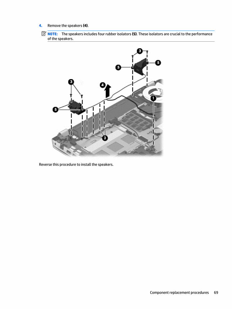
4. Remove the speakers (4).
NOTE: The speakers includes four rubber isolators (5). These isolators are crucial to the performanceof the speakers.
Reverse this procedure to install the speakers.
Component replacement procedures 69

TouchPad assembly
Description Spare part number
TouchPad assembly (includes TouchPad bracket, TouchPad button board, TouchPad, and cables) 760041-001
Tape kit, includes tape, gasket, Mylar insulator, top case insulator, and gasket boss 801975-001
Before removing the TouchPad, follow these steps:
1. Turn off the computer. If you are unsure whether the computer is off or in Hibernation, turn thecomputer on, and then shut it down through the operating system.
2. Disconnect the power from the computer by unplugging the power cord from the computer.
3. Disconnect all external devices from the computer.
4. Remove the battery (see Battery on page 34), and then remove the following components:
a. Service cover (see WLAN module on page 35)
b. Hard drive (see Hard drive on page 38)
c. Base enclosure (see Base enclosure on page 45)
d. System board (see System board on page 56)
Remove the TouchPad:
1. Remove the six Phillips PM2.0×2.9 screws (1) that secure the TouchPad bracket to the top cover.
2. Remove the TouchPad bracket (2).
3. Release the grounding tape (1) that connects the TouchPad to the top cover.
70 Chapter 6 Removal and replacement procedures for Authorized Service Provider parts
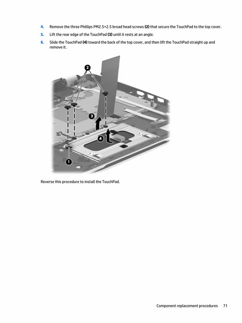
4. Remove the three Phillips PM2.5×2.5 broad head screws (2) that secure the TouchPad to the top cover.
5. Lift the rear edge of the TouchPad (3) until it rests at an angle.
6. Slide the TouchPad (4) toward the back of the top cover, and then lift the TouchPad straight up andremove it.
Reverse this procedure to install the TouchPad.
Component replacement procedures 71
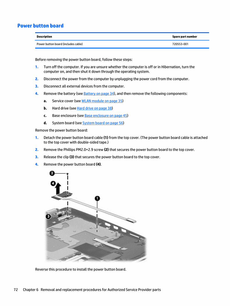
Power button board
Description Spare part number
Power button board (includes cable) 720553-001
Before removing the power button board, follow these steps:
1. Turn off the computer. If you are unsure whether the computer is off or in Hibernation, turn thecomputer on, and then shut it down through the operating system.
2. Disconnect the power from the computer by unplugging the power cord from the computer.
3. Disconnect all external devices from the computer.
4. Remove the battery (see Battery on page 34), and then remove the following components:
a. Service cover (see WLAN module on page 35)
b. Hard drive (see Hard drive on page 38)
c. Base enclosure (see Base enclosure on page 45)
d. System board (see System board on page 56)
Remove the power button board:
1. Detach the power button board cable (1) from the top cover. (The power button board cable is attachedto the top cover with double-sided tape.)
2. Remove the Phillips PM2.0×2.9 screw (2) that secures the power button board to the top cover.
3. Release the clip (3) that secures the power button board to the top cover.
4. Remove the power button board (4).
Reverse this procedure to install the power button board.
72 Chapter 6 Removal and replacement procedures for Authorized Service Provider parts
Keyboard
NOTE: The keyboard spare part kit includes a keyboard cable.
For use in country/region Spare part number
Keyboard in natural silver finish with backlight (includes keyboard cable and backlight cable):
For use in Canada 760743-DB1 For use in Taiwan 760743-AB1
For use in Japan 760743-291 For use in Thailand 760743-281
For use in Latin America 760743-161 For use in the United States 760743-001
For use in South Korea 760743-AD1
Before removing the keyboard, follow these steps:
1. Turn off the computer. If you are unsure whether the computer is off or in Hibernation, turn thecomputer on, and then shut it down through the operating system.
2. Disconnect the power from the computer by unplugging the power cord from the computer.
3. Disconnect all external devices from the computer.
4. Remove the battery (see Battery on page 34), and then remove the following components:
a. Service cover (see WLAN module on page 35)
b. Hard drive (see Hard drive on page 38)
c. Base enclosure (see Base enclosure on page 45)
d. System board (see System board on page 56)
e. Connector board (see Connector board on page 64)
f. Subwoofer (see Subwoofer on page 66)
g. Rear speaker (see Speakers on page 68)
h. Power button board (see Power button board on page 72)
Remove the keyboard:
1. Remove the seven Phillips PM2.0×2.9 screws (1) that secure the keyboard shield to the computer.
2. Release the ground loop tape (2).
Component replacement procedures 73
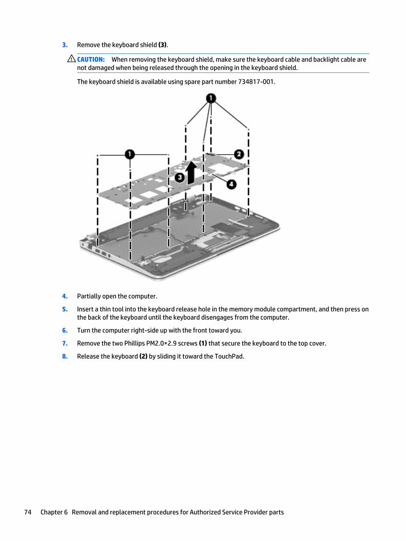
3. Remove the keyboard shield (3).
CAUTION: When removing the keyboard shield, make sure the keyboard cable and backlight cable arenot damaged when being released through the opening in the keyboard shield.
The keyboard shield is available using spare part number 734817-001.
4. Partially open the computer.
5. Insert a thin tool into the keyboard release hole in the memory module compartment, and then press onthe back of the keyboard until the keyboard disengages from the computer.
6. Turn the computer right-side up with the front toward you.
7. Remove the two Phillips PM2.0×2.9 screws (1) that secure the keyboard to the top cover.
8. Release the keyboard (2) by sliding it toward the TouchPad.
74 Chapter 6 Removal and replacement procedures for Authorized Service Provider parts
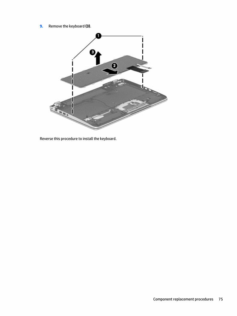
9. Remove the keyboard (3).
Reverse this procedure to install the keyboard.
Component replacement procedures 75
7 Using Setup Utility (BIOS)
Setup Utility, or Basic Input/Output System (BIOS), controls communication between all the input and outputdevices on the system (such as disk drives, display, keyboard, mouse, and printer). Setup Utility (BIOS)includes settings for the types of devices installed, the startup sequence of the computer, and the amount ofsystem and extended memory.
Starting Setup Utility (BIOS)CAUTION: Use extreme care when making changes in Setup Utility (BIOS). Errors can prevent the computerfrom operating properly.
NOTE: If your tablet has a keyboard base, connect the tablet to the keyboard base before beginning thesteps in this chapter.
● Computers or tablets with keyboards:
▲ Turn on or restart the computer, quickly press esc, and then press f10.
● Tablets without keyboards:
1. Turn on or restart the tablet, and then quickly hold down the volume down button.
- or -
Turn on or restart the tablet, and then quickly hold down the Windows button.
2. Tap f10.
Updating the BIOSUpdated versions of the BIOS may be available on the HP website.
Most BIOS updates on the HP website are packaged in compressed files called SoftPaqs.
Some download packages contain a file named Readme.txt, which contains information regarding installingand troubleshooting the file.
Determining the BIOS version
To determine whether available BIOS updates contain later BIOS versions than the one currently installed onthe computer, you need to know the version of the system BIOS that is installed.
BIOS version information (also known as ROM date and System BIOS) can be revealed from the Start screen bytyping support, selecting the HP Support Assistant app, and then selecting System Information, or byusing Setup Utility (BIOS).
1. Start Setup Utility (BIOS) (see Starting Setup Utility (BIOS) on page 76).
2. Select Main, and then make note of your BIOS version.
3. Select Exit, select Exit Discarding Changes, and then follow the on-screen instructions.
76 Chapter 7 Using Setup Utility (BIOS)
Downloading a BIOS update
CAUTION: To reduce the risk of damage to the computer or an unsuccessful installation, download andinstall a BIOS update only when the computer is connected to reliable external power using the AC adapter.Do not download or install a BIOS update while the computer is running on battery power, docked in anoptional docking device, or connected to an optional power source. During the download and installation,follow these instructions:
● Do not disconnect power from the computer by unplugging the power cord from the AC outlet.
● Do not shut down the computer or initiate Sleep.
● Do not insert, remove, connect, or disconnect any device, cable, or cord.
NOTE: If your computer is connected to a network, consult the network administrator before installing anysoftware updates, especially system BIOS updates.
1. From the Start screen, type support, and then select the HP Support Assistant app.
‒ or –
From the Windows desktop, click the question mark icon in the notification area, at the far right of thetaskbar.
2. Click Updates and tune-ups, and then click Check for HP updates now.
3. Follow the on-screen instructions.
4. At the download area, follow these steps:
a. Identify the most recent BIOS update and compare it to the BIOS version currently installed onyour computer. If the update is more recent than your BIOS, make a note of the date, name, orother identifier. You may need this information to locate the update later, after it has beendownloaded to your hard drive.
b. Follow the on-screen instructions to download your selection to the hard drive.
If the update is more recent than your BIOS, make a note of the path to the location on your harddrive where the BIOS update is downloaded. You will need to access this path when you are readyto install the update.
BIOS installation procedures vary. Follow any instructions that appear on the screen after the download iscomplete. If no instructions appear, follow these steps:
1. From the Start screen, type file, and then select File Explorer.
‒ or –
From the Windows desktop, right-click the Start button, and then select File Explorer.
2. Click your hard drive designation. The hard drive designation is typically Local Disk (C:).
3. Using the hard drive path you recorded earlier, open the folder on your hard drive that contains theupdate.
4. Double-click the file that has an .exe extension (for example, filename.exe).
The BIOS installation begins.
5. Complete the installation by following the on-screen instructions.
NOTE: After a message on the screen reports a successful installation, you can delete the downloaded filefrom your hard drive.
Updating the BIOS 77
8 Using HP PC Hardware Diagnostics (UEFI)
HP PC Hardware Diagnostics is a Unified Extensible Firmware Interface (UEFI) that allows you to rundiagnostic tests to determine whether the computer hardware is functioning properly. The tool runs outsidethe operating system so that it can isolate hardware failures from issues that are caused by the operatingsystem or other software components.
To start HP PC Hardware Diagnostics (UEFI):
1. Start Setup Utility:
● Computers or tablets with keyboards:
▲ Turn on or restart the computer, quickly press esc.
2. Press or tap f2.
The BIOS searches 3 places for the diagnostic tools, in the following order:
a. Connected USB drive
NOTE: To download the HP PC Hardware Diagnostics (UEFI) tool to a USB drive, see DownloadingHP PC Hardware Diagnostics (UEFI) to a USB device on page 78.
b. Hard drive
c. BIOS
3. When the diagnostic tool opens, use the keyboard arrow keys to select the type of diagnostic test youwant to run, and then follow the on-screen instructions.
NOTE: If you need to stop a diagnostic test, press or tap esc.
NOTE: To start the Setup Utility, your computer must be in notebook mode and you must use the keyboardattached to your notebook. The on-screen keyboard which displays in tablet mode cannot access the SetupUtility.
Downloading HP PC Hardware Diagnostics (UEFI) to a USB deviceNOTE: Instructions for downloading HP PC Hardware Diagnostics (UEFI) are provided in English only.
There are two options to download HP PC Hardware Diagnostics to a USB device:
Option 1: HP PC Diagnostics homepage— Provides access to the latest UEFI version
1. Go to http://hp.com/go/techcenter/pcdiags.
2. Click the UEFI Download link, and then select Run.
Option 2: Support and Drivers pages—Provide downloads for a specific product for earlier and laterversions
1. Go to http://www.hp.com.
2. Point to Support, located at the top of the page, and then click Download Drivers.
78 Chapter 8 Using HP PC Hardware Diagnostics (UEFI)

3. In the text box, enter the product name, and then click Go.
– or –
Click Find Now to let HP automatically detect your product.
4. Select your computer model, and then select your operating system.
5. In the Diagnostic section, click HP UEFI Support Environment.
– or –
Click Download, and then select Run.
Downloading HP PC Hardware Diagnostics (UEFI) to a USB device 79
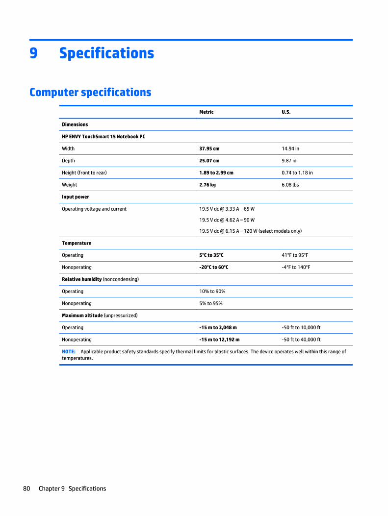
9 Specifications
Computer specifications
Metric U.S.
Dimensions
HP ENVY TouchSmart 15 Notebook PC
Width 37.95 cm 14.94 in
Depth 25.07 cm 9.87 in
Height (front to rear) 1.89 to 2.99 cm 0.74 to 1.18 in
Weight 2.76 kg 6.08 lbs
Input power
Operating voltage and current 19.5 V dc @ 3.33 A – 65 W
19.5 V dc @ 4.62 A – 90 W
19.5 V dc @ 6.15 A – 120 W (select models only)
Temperature
Operating 5°C to 35°C 41°F to 95°F
Nonoperating -20°C to 60°C -4°F to 140°F
Relative humidity (noncondensing)
Operating 10% to 90%
Nonoperating 5% to 95%
Maximum altitude (unpressurized)
Operating -15 m to 3,048 m -50 ft to 10,000 ft
Nonoperating -15 m to 12,192 m -50 ft to 40,000 ft
NOTE: Applicable product safety standards specify thermal limits for plastic surfaces. The device operates well within this range oftemperatures.
80 Chapter 9 Specifications
10 Backing up, restoring, and recovering
This chapter provides information about the following processes. The information in the chapter is standardprocedure for most models.
● Creating recovery media and backups
● Restoring and recovering your system
For additional information, refer to the HP Support Assistant.
▲ From the Start screen, type support, and then select the HP Support Assistant app.
- or -
From the Windows desktop, click the question mark icon in the notification area, at the far right of thetaskbar.
IMPORTANT: If you will be using F11 startup recovery or USB media recovery to recover your system, thetablet battery must have at least 70% battery power remaining before starting the recovery process.
Creating recovery media and backupsThe following methods of creating recovery media and backups are available on select models only. Choosethe available method according to your computer model.
● Use HP Recovery Manager after you successfully set up the computer to create HP Recovery media. Thisstep creates a backup of the HP Recovery partition on the computer. The backup can be used to reinstallthe original operating system in cases where the hard drive is corrupted or has been replaced. Forinformation on creating recovery media, see Creating HP Recovery media (select models only)on page 81. For information on the recovery options that are available using the recovery media, seeRecovering using HP Recovery Manager on page 83.
● Use Windows tools to create system restore points and create backups of personal information.
For more information, see Using Windows tools on page 82.
NOTE: If storage is 32 GB or less, Microsoft System Restore is disabled by default.
Creating HP Recovery media (select models only)
IMPORTANT: If your computer does not list a Recovery Media Creation option, you can obtain recoverymedia for your system from support. See the Worldwide Telephone Numbers booklet included with thecomputer. You can also find contact information from the HP website. Go to http://www.hp.com/support,select your country or region, and follow the on-screen instructions.
HP Recovery Manager is a software program that allows you to create recovery media after you successfullyset up the computer. HP Recovery media can be used to perform system recovery if the hard drive becomescorrupted. System recovery reinstalls the original operating system and the software programs installed atthe factory and then configures the settings for the programs. HP Recovery media can also be used tocustomize the system or restore the factory image if you replace the hard drive.
Creating recovery media and backups 81
● Only one set of recovery media can be created. Handle these recovery tools carefully, and keep them ina safe place.
● HP Recovery Manager examines the computer and determines the required storage capacity for themedia that will be required.
● To create recovery discs, your computer must have an optical drive with DVD writer capability, and youmust use only high-quality blank DVD-R, DVD+R, DVD-R DL, or DVD+R DL discs. Do not use rewritablediscs such as CD±RW, DVD±RW, double-layer DVD±RW, or BD-RE (rewritable Blu-ray) discs; they are notcompatible with HP Recovery Manager software. Or, instead, you can use a high-quality blank USB flashdrive.
● If your computer does not include an integrated optical drive with DVD writer capability, but you wouldlike to create DVD recovery media, you can use an external optical drive (purchased separately) tocreate recovery discs, or you can obtain recovery discs for your computer from support. See theWorldwide Telephone Numbers booklet included with the computer. You can also find contactinformation from the HP website. Go to http://www.hp.com/support, select your country or region, andfollow the on-screen instructions. If you use an external optical drive, it must be connected directly to aUSB port on the computer; the drive cannot be connected to a USB port on an external device, such as aUSB hub.
● Be sure that the computer is connected to AC power before you begin creating the recovery media.
● The creation process can take an hour or more. Do not interrupt the creation process.
● If necessary, you can exit the program before you have finished creating all of the recovery DVDs. HPRecovery Manager will finish burning the current DVD. The next time you start HP Recovery Manager,you will be prompted to continue, and the remaining discs will be burned.
To create HP Recovery media:
IMPORTANT: For tablets with a detachable keyboard, connect the keyboard to the keyboard dock beforebeginning these steps (select models only).
1. From the Start screen, type recovery, and then select HP Recovery Manager.
2. Select Recovery Media Creation, and then follow the on-screen instructions.
If you ever need to recover the system, see Recovering using HP Recovery Manager on page 83.
Using Windows toolsYou can create system restore points and create backups of personal information using Windows tools.
NOTE: If storage is 32 GB or less, Microsoft System Restore is disabled by default.
▲ From the Start screen, type help, and then select Help and Support.
‒ or –
From the Windows desktop, click the question mark icon in the notification area, at the far right of thetaskbar.
For more information and steps, see Help and Support.
Restore and recoveryThere are several options for recovering your system. Choose the method that best matches your situationand level of expertise:
82 Chapter 10 Backing up, restoring, and recovering
IMPORTANT: Not all methods are available on all models.
● Windows offers several options for restoring from backup, refreshing the computer, and resetting thecomputer to its original state. For more information see Help and Support.
▲ From the Start screen, type support, and then select the HP Support Assistant app.
- or -
From the Windows desktop, click the question mark icon in the notification area, at the far right ofthe taskbar.
● If you need to correct a problem with a preinstalled application or driver, use the Drivers andApplications Reinstall option of HP Recovery Manager to reinstall the individual application or driver.
▲ From the Start screen, type recovery, select HP Recovery Manager, select Drivers andApplications Reinstall, and then follow the on-screen instructions.
● On select models, if you want to reset your computer using a minimized image, you can choose the HPMinimized Image Recovery option from the HP Recovery partition or HP Recovery media. MinimizedImage Recovery installs only drivers and hardware-enabling applications. Other applications included inthe image continue to be available for installation through the Drivers and Applications Reinstall optionin HP Recovery Manager.
For more information, see Recovering using HP Recovery Manager on page 83.
● If you want to recover the Windows partition to original factory content, you can choose the SystemRecovery option from the HP Recovery partition (select models only) or use the HP Recovery media. Formore information, see Recovering using HP Recovery Manager on page 83. If you have not alreadycreated recovery media, see Creating HP Recovery media (select models only) on page 81.
● On select models, if you want to recover the computer's original factory partition and content , or if youhave replaced the hard drive, you can use the Factory Reset option of HP Recovery media. For moreinformation, see Recovering using HP Recovery Manager on page 83.
● On select models, if you want to remove the recovery partition to reclaim hard drive space, HP RecoveryManager offers the Remove Recovery Partition option.
For more information, see Removing the HP Recovery partition (select models only) on page 85.
Recovering using HP Recovery Manager
HP Recovery Manager software allows you to recover the computer to its original factory state by using theHP Recovery media that you either created or that you obtained from support, or by using the HP Recoverypartition (select models only). If you have not already created recovery media, see Creating HP Recoverymedia (select models only) on page 81.
What you need to know before you get started
● HP Recovery Manager recovers only software that was installed at the factory. For software notprovided with this computer, you must either download the software from the manufacturer's websiteor reinstall the software from the media provided by the manufacturer.
IMPORTANT: Recovery through HP Recovery Manager should be used as a final attempt to correctcomputer issues.
● HP Recovery media must be used if the computer hard drive fails. If you have not already createdrecovery media, see Creating HP Recovery media (select models only) on page 81.
Restore and recovery 83
● To use the Factory Reset option (select models only), you must use HP Recovery media. If you have notalready created recovery media, see Creating HP Recovery media (select models only) on page 81.
● If your computer does not allow the creation of HP Recovery media or if the HP Recovery media doesnot work, you can obtain recovery media for your system from support. See the Worldwide TelephoneNumbers booklet included with the computer. You can also find contact information from the HPwebsite. Go to http://www.hp.com/support, select your country or region, and follow the on-screeninstructions.
IMPORTANT: HP Recovery Manager does not automatically provide backups of your personal data. Beforebeginning recovery, back up any personal data you want to retain.
Using HP Recovery media, you can choose from one of the following recovery options:
NOTE: Only the options available for your computer display when you start the recovery process.
● System Recovery—Reinstalls the original operating system, and then configures the settings for theprograms that were installed at the factory.
● Minimized Image Recovery (select models only)—Reinstalls the operating system and all hardware-related drivers and software, but not other software applications.
● Factory Reset—Restores the computer to its original factory state by deleting all information from thehard drive and re-creating the partitions. Then it reinstalls the operating system and the software thatwas installed at the factory.
The HP Recovery partition (select models only) allows System Recovery and Minimized Image Recovery(select models only).
Using the HP Recovery partition (select models only)
The HP Recovery partition allows you to perform a system recovery or minimized image recovery (selectmodels only) without the need for recovery discs or a recovery USB flash drive. This type of recovery can beused only if the hard drive is still working.
To start HP Recovery Manager from the HP Recovery partition:
IMPORTANT: For tablets with a detachable keyboard, connect the keyboard to the keyboard dock beforebeginning these steps (select models only).
1. From the Start screen, type recovery, select Recovery Manager, and then select HP RecoveryEnvironment.
- or-
Press f11 while the computer boots, or press and hold f11 as you press the power button.
2. Select Troubleshoot from the boot options menu.
3. Select Recovery Manager, and then follow the on-screen instructions.
Using HP Recovery media to recover
You can use HP Recovery media to recover the original system. This method can be used if your system doesnot have an HP Recovery partition or if the hard drive is not working properly.
84 Chapter 10 Backing up, restoring, and recovering
1. If possible, back up all personal files.
2. Insert the HP Recovery media, and then restart the computer.
NOTE: If the computer does not automatically restart in HP Recovery Manager, change the computerboot order. See Changing the computer boot order on page 85.
3. Follow the on-screen instructions.
Changing the computer boot order
If your computer does not restart in HP Recovery Manager, you can change the computer boot order, which isthe order of devices listed in BIOS where the computer looks for startup information. You can change theselection for an optical drive or a USB flash drive.
To change the boot order:
IMPORTANT: For tablets with a detachable keyboard, connect the keyboard to the keyboard dock beforebeginning these steps (select models only).
1. Insert the HP Recovery media.
2. Start Computer Setup:
For computers or tablets with keyboards attached:
▲ Turn on or restart the computer or tablet, quickly press esc, and then press f9 for boot options.
For computers or tablets without keyboards attached:
▲ Turn on or restart the computer, quickly press the volume down button, and then tap f9 for bootoptions.
- or -
Turn on or restart the computer, quickly press the Windows button, and then tap f9 for bootoptions.
3. Select the optical drive or USB flash drive from which you want to boot.
4. Follow the on-screen instructions.
Removing the HP Recovery partition (select models only)
HP Recovery Manager software allows you to remove the HP Recovery partition to free up hard drive space.
IMPORTANT: After you remove the HP Recovery partition, you can no longer use the Windows Refreshoption or the Windows option to remove everything and reinstall Windows. In addition, you will not be able toperform System Recovery or Minimized Image Recovery from the HP Recovery partition. So before youremove the Recovery partition, create HP Recovery media; see Creating HP Recovery media (select modelsonly) on page 81.
Follow these steps to remove the HP Recovery partition:
1. From the Start screen, type recovery, and then select HP Recovery Manager.
2. Select Remove Recovery Partition, and then follow the on-screen instructions.
Restore and recovery 85
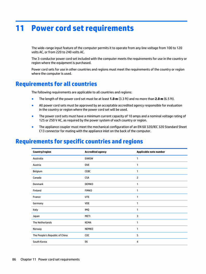
11 Power cord set requirements
The wide-range input feature of the computer permits it to operate from any line voltage from 100 to 120volts AC, or from 220 to 240 volts AC.
The 3-conductor power cord set included with the computer meets the requirements for use in the country orregion where the equipment is purchased.
Power cord sets for use in other countries and regions must meet the requirements of the country or regionwhere the computer is used.
Requirements for all countriesThe following requirements are applicable to all countries and regions:
● The length of the power cord set must be at least 1.0 m (3.3 ft) and no more than 2.0 m (6.5 ft).
● All power cord sets must be approved by an acceptable accredited agency responsible for evaluationin the country or region where the power cord set will be used.
● The power cord sets must have a minimum current capacity of 10 amps and a nominal voltage rating of125 or 250 V AC, as required by the power system of each country or region.
● The appliance coupler must meet the mechanical configuration of an EN 60 320/IEC 320 Standard SheetC13 connector for mating with the appliance inlet on the back of the computer.
Requirements for specific countries and regions
Country/region Accredited agency Applicable note number
Australia EANSW 1
Austria OVE 1
Belgium CEBC 1
Canada CSA 2
Denmark DEMKO 1
Finland FIMKO 1
France UTE 1
Germany VDE 1
Italy IMQ 1
Japan METI 3
The Netherlands KEMA 1
Norway NEMKO 1
The People's Republic of China COC 5
South Korea EK 4
86 Chapter 11 Power cord set requirements
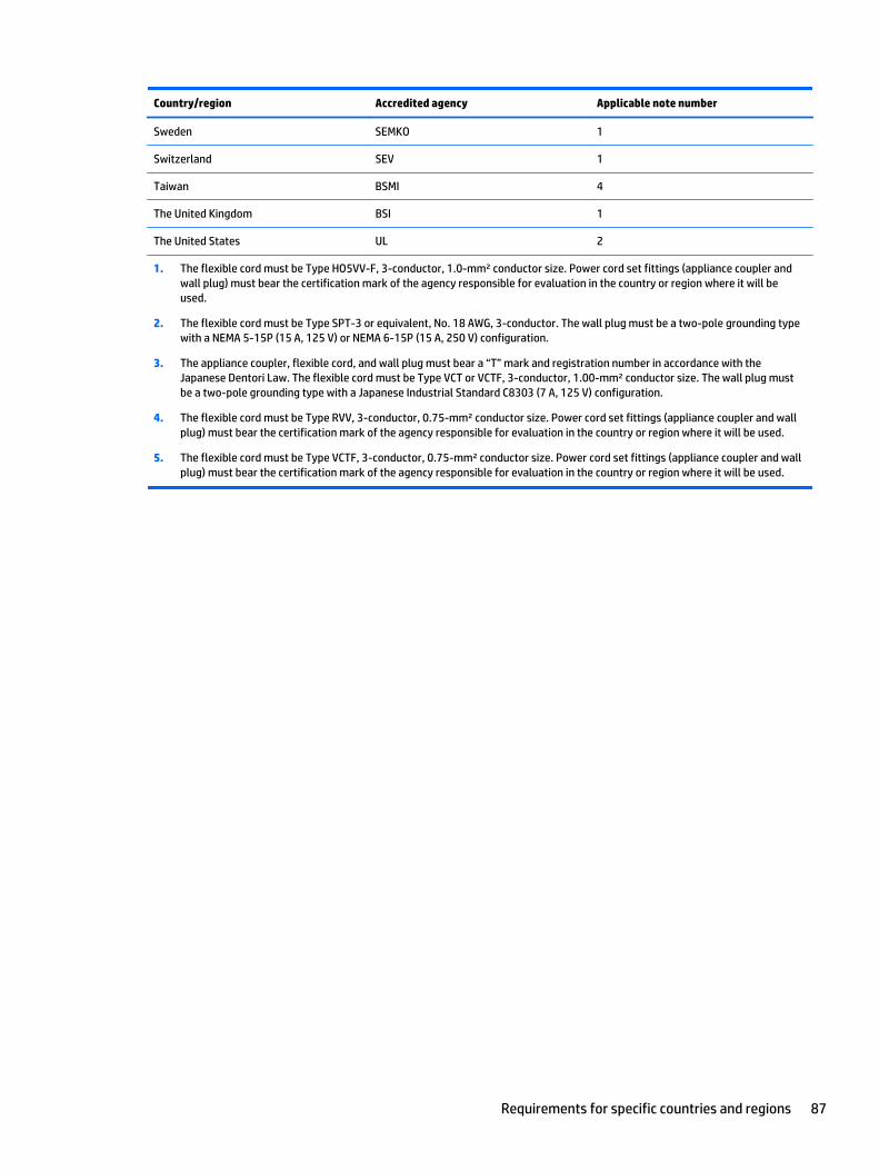
Country/region Accredited agency Applicable note number
Sweden SEMKO 1
Switzerland SEV 1
Taiwan BSMI 4
The United Kingdom BSI 1
The United States UL 2
1. The flexible cord must be Type HO5VV-F, 3-conductor, 1.0-mm² conductor size. Power cord set fittings (appliance coupler andwall plug) must bear the certification mark of the agency responsible for evaluation in the country or region where it will beused.
2. The flexible cord must be Type SPT-3 or equivalent, No. 18 AWG, 3-conductor. The wall plug must be a two-pole grounding typewith a NEMA 5-15P (15 A, 125 V) or NEMA 6-15P (15 A, 250 V) configuration.
3. The appliance coupler, flexible cord, and wall plug must bear a “T” mark and registration number in accordance with theJapanese Dentori Law. The flexible cord must be Type VCT or VCTF, 3-conductor, 1.00-mm² conductor size. The wall plug mustbe a two-pole grounding type with a Japanese Industrial Standard C8303 (7 A, 125 V) configuration.
4. The flexible cord must be Type RVV, 3-conductor, 0.75-mm² conductor size. Power cord set fittings (appliance coupler and wallplug) must bear the certification mark of the agency responsible for evaluation in the country or region where it will be used.
5. The flexible cord must be Type VCTF, 3-conductor, 0.75-mm² conductor size. Power cord set fittings (appliance coupler and wallplug) must bear the certification mark of the agency responsible for evaluation in the country or region where it will be used.
Requirements for specific countries and regions 87
12 Recycling
When a non-rechargeable or rechargeable battery has reached the end of its useful life, do not dispose of thebattery in general household waste. Follow the local laws and regulations in your area for battery disposal.
HP encourages customers to recycle used electronic hardware, HP original print cartridges, and rechargeablebatteries. For more information about recycling programs, see the HP Web site at http://www.hp.com/recycle.
88 Chapter 12 Recycling
Index
AAC adapter 13AC adapter, spare part numbers 20,
23action keys 10
identifying 10antenna
removal 54spare part number 22, 23, 55
Antenna Kit, spare part number 22,23, 55
audio, product description 2audio-out (headphone)/audio-in
(microphone) jack 13
Bbackups 81base enclosure
removal 45spare part numbers 18, 25, 26,
45battery
removal 34spare part numbers 19, 23, 34
battery cover, identifying 14battery release latch 15BIOS
determining version 76downloading an update 77starting the Setup Utility 76updating 76
boot orderchanging 85
buttonsleft TouchPad 7power 9right TouchPad 7
Ccables, service considerations 29caps lock light, identifying 8chipset, product description 1components
bottom 14display 6
left side 12right side 13top 7
computermajor components 16specifications 80
connector boardremoval 64spare part numbers 17, 26, 64
connector, power 14connectors, service considerations
29counterbalance weight, spare part
number 24
Ddisplay assembly
removal 47spare part numbers 17, 24, 26,
47display bezel
removal 50spare part number 21, 23, 51
display enclosure, spare partnumber 22, 23
Display Hinge Kit, spare partnumber 24
display panelproduct description 1removal 51spare part numbers 21, 24, 52
display panel cableremoval 52spare part number 21, 24, 53
drives, preventing damage 29DVD±RW Double-Layer with
SuperMulti Driveprecautions 29spare part number 22, 25
Eelectrostatic discharge 29equipment guidelines 32esc key, identifying 10Ethernet, product description 2
Ffan
removal 55spare part number 18, 23, 55
fingerprint reader lightidentifying 8
fingerprint reader, identifying 9fn key, identifying 10
Ggraphics, product description 1grounding guidelines 29guidelines
equipment 32grounding 29packaging 31transporting 31workstation 31
Hhard drive
identifying 14precautions 29product description 2removal 38spare part numbers 19, 22, 23,
24, 25, 26, 38hard drive bracket
illustrated 23removal 39
hard drive connector cableillustrated 23removal 39
Hard Drive Hardware Kitcontents 23spare part number 19, 23, 24
hard drive light 12HDMI port
identifying 12HDMI-to-VGA adapter, spare part
number 20, 23heat sink
removal 60spare part numbers 18, 24, 26,
60
Index 89
hingeremoval 53spare part number 21, 24, 53
hinge bracketremoval 53spare part number 54
hinge coverremoval 51spare part number 51
HP PC Hardware Diagnostics (UEFI)downloading 78
HP Recovery Managercorrecting boot problems 85starting 84
HP Recovery mediacreating 81recovery 84
HP Recovery partitionrecovery 84removing 85
Iintegrated numeric keypad,
identifying 10internal display switch, identifying
6internal microphones, identifying 6
Jjacks
audio-out (headphone)/audio-in(microphone) 13
network 13RJ-45 (network) 13
Kkeyboard
product description 3removal 73spare part numbers 17, 25, 26,
73keyboard shield
removal 73spare part number 17, 24, 74
keysaction 10esc 10fn 10Windows 10
Llatch, battery release 15left control zone, identifying 7lights
AC adapter 13caps lock 8fingerprint reader 8hard drive 12mute 8power 8, 12RJ-45 (network) status 13wireless 8
Mmass storage device
illustrated 22precautions 29spare part numbers 22
memory card reader, identifying 12memory card, identifying 12memory module
identifying 14product description 1removal 40spare part numbers 19, 23, 40
microphoneproduct description 2
minimized image recovery 84minimized image, creating 83model name 1mute light, identifying 8
Nnetwork jack, identifying 13
Ooperating system, product
description 3optical drive
precautions 29spare part number 22, 25
original system recovery 83
Ppackaging guidelines 31plastic parts, service
considerations 28pointing device, product
description 3ports
HDMI 12
product description 3USB 2.0 13USB 3.0 12USB 3.0 (powered) charging 12
power button boardremoval 72spare part number 17, 24, 72
power button, identifying 9power connector cable
removal 65spare part number 17, 24, 65
power connector, identifying 14power cord
set requirements 86spare part number 20, 25
power lights, identifying 8, 12power requirements, product
description 3processor
removal 62spare part numbers 18, 24, 26,
62processor, product description 1product description
audio 2chipset 1display panel 1Ethernet 2external media cards 3graphics 1hard drive 2internal card expansion 3keyboard 3memory module 1microphone 2operating system 3pointing device 3ports 3power requirements 3processors 1product name 1security 3serviceability 3video 2wireless 2
product name 1
Rrecover
options 82
90 Index
recoverydiscs 82, 84HP Recovery Manager 83media 84starting 84supported discs 82system 83USB flash drive 84using HP Recovery media 82
recovery mediacreating 81creating using HP Recovery
Manager 82recovery partition
removing 85removal/replacement
procedures 33, 43right control zone, identifying 7RJ-45 (network) jack, identifying 13RJ-45 (network) status lights,
identifying 13RTC battery
removal 43spare part numbers 18, 23, 43
rubber feetremoval 45spare part number 45
Rubber Kit, spare part number 18,24
SScrew Kit, spare part number 20, 24security cable slot, identifying 12security, product description 3service considerations
cables 29connectors 29plastic parts 28
service coverremoval 35spare part number 19, 24, 36
service tag 15serviceability, product description 3slots
memory card reader 12security cable 12
speakersidentifying 9
removal 66, 68spare part numbers 17, 18, 24,
66, 68specifications 80subwoofer
removal 66spare part number 18, 24, 66
supported discs, recovery 82system board
removal 56spare part numbers 17, 25, 26,
27, 56system recovery 83system restore point
creating 82system restore point, creating 81
Ttools required 28top cover, spare part numbers 17,
25, 26TouchPad assembly
removal 70spare part number 17, 25, 70
TouchPad zone, identifying 7TouchPad, buttons 7transporting guidelines 31
UUSB 2.0 port, identifying 13USB 3.0 charging (powered) port,
identifying 12USB 3.0 ports, identifying 12
Vvents, identifying 12, 15video, product description 2
Wwebcam
identifying 6webcam light, identifying 6webcam/microphone module
removal 54spare part number 21, 23, 54
Windowssystem restore point 81, 82
Windows key, identifying 10Windows tools
using 82
wireless antennaremoval 54spare part number 22, 23, 55
wireless light 8wireless, product description 2WLAN antennas, identifying 6WLAN module
removal 35spare part numbers 18, 23, 25,
35workstation guidelines 31
Index 91