Embed Size (px)
Citation preview

HP ENVY 17 Notebook PCHP ENVY 15 Notebook PC
Maintenance and Service Guide

© Copyright 2014 Hewlett-PackardDevelopment Company, L.P.
Bluetooth is a trademark owned by itsproprietor and used by Hewlett-PackardCompany under license. Intel is atrademark of Intel Corporation in the U.S.and other countries. Leap Motion, the LeapMotion logo, and Airspace are thetrademarks of Leap Motion, Inc. and areused here by permission. Microsoft andWindows are U.S. registered trademarks ofMicrosoft Corporation. SD Logo is atrademark of its proprietor.
The information contained herein is subjectto change without notice. The onlywarranties for HP products and services areset forth in the express warranty statementsaccompanying such products and services.Nothing herein should be construed asconstituting an additional warranty. HP shallnot be liable for technical or editorial errorsor omissions contained herein.
Second Edition: July 2014
First Edition: May 2014
Document Part Number: 764148-002
Product notice
This guide describes features that arecommon to most models. Some featuresmay not be available on your computer.
Not all features are available in all editionsof Windows 8. This computer may requireupgraded and/or separately purchasedhardware, drivers and/or software to takefull advantage of Windows 8 functionality.See http://www.microsoft.com for details.
Software terms
By installing, copying, downloading, orotherwise using any software productpreinstalled on this computer, you agree tobe bound by the terms of the HP End UserLicense Agreement (EULA). If you do notaccept these license terms, your soleremedy is to return the entire unusedproduct (hardware and software) within 14days for a refund subject to the refundpolicy of your place of purchase.
For any further information or to request afull refund of the computer, please contactyour local point of sale (the seller).

Important Notice about Customer Self-Repair PartsCAUTION: Your computer includes Customer Self-Repair parts and parts that should only beaccessed by an authorized service provider. See Chapter 5, "Removal and replacement proceduresfor Customer Self-Repair parts," for details. Accessing parts described in Chapter 6, "Removal andreplacement procedures for Authorized Service Provider only parts," can damage the computer orvoid your warranty.
iii

iv Important Notice about Customer Self-Repair Parts

Safety warning noticeWARNING! To reduce the possibility of heat-related injuries or of overheating the device, do notplace the device directly on your lap or obstruct the device air vents. Use the device only on a hard,flat surface. Do not allow another hard surface, such as an adjoining optional printer, or a softsurface, such as pillows or rugs or clothing, to block airflow. Also, do not allow the AC adapter tocontact the skin or a soft surface, such as pillows or rugs or clothing, during operation. The deviceand the AC adapter comply with the user-accessible surface temperature limits defined by theInternational Standard for Safety of Information Technology Equipment (IEC 60950).
v

vi Safety warning notice

Table of contents
1 Product description ........................................................................................................................................... 1
2 External component identification ..................................................................................................................... 5Finding your hardware and software information ................................................................................. 5
Locating hardware ............................................................................................................... 5Locating software ................................................................................................................. 5
Right side ............................................................................................................................................. 6Left side ................................................................................................................................................ 7Display .................................................................................................................................................. 9Top ..................................................................................................................................................... 10
TouchPad .......................................................................................................................... 10Lights ................................................................................................................................. 11Buttons, speakers, and fingerprint reader .......................................................................... 12Keys ................................................................................................................................... 13
Bottom ................................................................................................................................................ 14Labels ................................................................................................................................................. 15
3 Illustrated parts catalog ................................................................................................................................... 16Computer major components ............................................................................................................. 16Display assembly subcomponents ..................................................................................................... 23Mass storage devices ......................................................................................................................... 26Miscellaneous parts ............................................................................................................................ 27Sequential part number listing ............................................................................................................ 28
4 Removal and replacement procedures preliminary requirements .................................................................. 36Tools required .................................................................................................................................... 36Service considerations ....................................................................................................................... 36
Plastic parts ....................................................................................................................... 36Cables and connectors ...................................................................................................... 37Drive handling .................................................................................................................... 37
Grounding guidelines ......................................................................................................................... 38Electrostatic discharge damage ......................................................................................... 38
Packaging and transporting guidelines ............................................................. 39Workstation guidelines ...................................................................................... 39Equipment guidelines ........................................................................................ 40
vii

5 Removal and replacement procedures for Customer Self-Repair parts ......................................................... 41Component replacement procedures ................................................................................................. 41
Battery ............................................................................................................................... 42Optical drive ....................................................................................................................... 43
6 Removal and replacement procedures for Authorized Service Provider parts ............................................... 45Component replacement procedures ................................................................................................. 45
Base enclosure .................................................................................................................. 46Display panel ..................................................................................................................... 51WLAN module .................................................................................................................... 59TouchPad button board ..................................................................................................... 61Battery Board (select models only) .................................................................................... 62Optical drive connector ...................................................................................................... 62Subwoofer .......................................................................................................................... 63USB board ......................................................................................................................... 65Hard drive .......................................................................................................................... 66System board ..................................................................................................................... 67Speakers ............................................................................................................................ 71Memory modules ............................................................................................................... 72RTC battery ....................................................................................................................... 74Fingerprint reader board (select models only) ................................................................... 75Power connector cable ...................................................................................................... 76Fan ..................................................................................................................................... 77Heat sink ............................................................................................................................ 78Power button board ........................................................................................................... 80
7 Windows – Using Setup Utility (BIOS) and HP PC Hardware Diagnostics (UEFI) ......................................... 81Starting Setup Utility (BIOS) ............................................................................................................... 81Updating the BIOS ............................................................................................................................. 81
Determining the BIOS version ........................................................................................... 81Downloading a BIOS update ............................................................................................. 82
Using HP PC Hardware Diagnostics (UEFI) ...................................................................................... 83Downloading HP PC Hardware Diagnostics (UEFI) to a USB device ............................... 83
8 Windows 7 Backing up, restoring, and recovering .......................................................................................... 84Creating backups ............................................................................................................................... 84
Creating recovery media to recover the original system .................................................... 84What you need to know ..................................................................................... 84
Creating the recovery media ............................................................ 85Creating system restore points .......................................................................................... 85
viii

What you need to know ..................................................................................... 85Creating a system restore point ........................................................................ 85
Backing up system and personal information .................................................................... 85Tips for a successful backup ............................................................................. 86What you need to know ..................................................................................... 86Creating a backup using Windows Backup and Restore .................................. 86
Restore and recovery ......................................................................................................................... 87Restoring to a previous system restore point .................................................................... 87Restoring specific files ....................................................................................................... 87
Restoring specific files using Windows Backup and Restore ............................ 87Recovering the original system using HP Recovery Manager ........................................... 87
What you need to know ..................................................................................... 87Recovering using HP Recovery partition (select models only) ......................... 88Recovering using the recovery media ............................................................... 88
Changing the computer boot order ................................................... 88
9 Windows 8.1 Backing up, restoring, and recovering ....................................................................................... 90Creating recovery media and backups ............................................................................................... 90
Creating HP Recovery media ............................................................................................ 90Restore and recovery ......................................................................................................................... 91
Recovering using HP Recovery Manager .......................................................................... 92What you need to know ..................................................................................... 92Using the HP Recovery partition (select models only) ...................................... 92Using HP Recovery media to recover ............................................................... 93Changing the computer boot order ................................................................... 93
Removing the HP Recovery partition ................................................................................. 93
10 Ubuntu Linux – Backing up, restoring, and recovering ................................................................................. 95Performing a system recovery ............................................................................................................ 95
Creating the restore DVDs ................................................................................................. 95Creating a restore image on a USB device ....................................................................... 95Performing recovery using the restore media .................................................................... 96
Backing up your information ............................................................................................................... 96
11 Specifications ................................................................................................................................................ 98Computer specifications ..................................................................................................................... 9843.9-cm (17.3-in), HD+ display specifications .................................................................................... 9939.6-cm (15.6-in) display specifications ........................................................................................... 100Hard drive specifications .................................................................................................................. 100DVD±RW SuperMulti Double-Layer Combination Drive specifications ............................................ 101
ix

12 Power cord set requirements ...................................................................................................................... 102Requirements for all countries .......................................................................................................... 102Requirements for specific countries and regions ............................................................................. 102
13 Recycling .................................................................................................................................................... 104
Index ................................................................................................................................................................. 105
x

1 Product description
NOTE: This document contains Microsoft Windows 8.1 and Windows 7 content.
Category Description
Product Name HP ENVY 17 Notebook PC
HP ENVY 15 Notebook PC
Processors Processors are attached to the system board.
● Intel® Quad Core i7-4710 HQ 2.50 GHz (SC turbo up to 3.50 GHz) processor (1600 MHz,6.0- MB L3 cache, 47 W) for use with HP ENVY 15 and 17 Notebook PC models available forWindows 8.1 and Windows 7
● Intel Dual Core i7-4510U (2.0 GHz, SC turbo up to 3.1 GHz), processor (1600 MHz/4 MB L3,15 W) for use with HP ENVY 15 and 17 Notebook PC models available for Windows 8.1 andWindows 7
● Intel Dual Core i7-4510U 850M 4 GB (2.0 GHz, SC turbo up to 3.1 GHz), processor (1600MHz/4 MB L3, 15W) for use with HP ENVY 17 Notebook PC models only
● Intel Dual Core i5-4210U 840M 2 GB (1.7 GHz SC turbo up to 2.7 GHz) processor (1600MHz, 3.0 MB L3 cache, 15 W) for use with HP ENVY 15 and 17 Notebook PC models
● Intel Dual Core i5-4210U (1.7 GHz SC turbo up to 2.7 GHz) processor (1600 MHz, 3.0 MB L3cache, 15 W) for use with HP ENVY 15 and 17 Notebook PC models
Chipset Intel HM87 Express Chipset
Intel Lynx Point-LP PCH (integrated in MCP)
Intel HM87 Express Chipset (for UMA non-touch computer models only)
Graphics Internal graphics:
● Intel HD Graphics 4600 internal graphics
● Intel HD Graphics 4400
● Supports HD Decode, DX11, and HDMI
● Supports Optimus
● Supports GPS (GPU Performance Scaling)
Switchable discrete graphics:
● NVIDIA N15P-GT (GeForce GTX 850M) with 4096 MB of dedicated video memory (256Mx16DDR3 900 MHz x 8 PCs, 1 GHz downgraded to 900 MHz))
● NVIDIA N15S-GT (GeForce 840M) with 2048 MB of dedicated video memory (256Mx16DDR3 900 MHz x 4 PCs, 1 GHz downgraded to 900 MHz)
● NVIDIA N15S-GT (GeForce 840M) with 4096 MB of dedicated video memory (256Mx16DDR3 900 MHz x 8 PCs, 1 GHz downgraded to 900 MHz)
Panel 17.3" high-definition (HD) light-emitting diode (WLED) BrightView (1600x900) display, (wedge6.0mm) SVA, Color Gamut 60%, supports LVDS, 200 nits non-touch only available for Windows8.1 and Windows 7
1

Category Description
17.3" high-definition (HD) light-emitting diode (WLED) Antiglare (1600x900) display, (wedge6.0mm) SVA, Color Gamut 60%, supports LVDS, 200 nits touch only available for Windows 8.1and Windows 7
17.3" high-definition (FHD) light-emitting diode (WLED) AntiGlare (1920x1080) (wedge 6.0mm)WVA, Color Gamut 72%, supports LVDS, 300 nits both touch and non-touch available forWindows 8.1 and Windows 7
15.6" HD WLED BrightView (1366x768) flat (3.8mm) SVA 200 nits, LVDS, non-touch onlyavailable for Windows 8.1 and Windows 7
15.6" HD WLED Antiglare (1366x768) flat (3.8mm) SVA 200 nits, LVDS, Touch only available forWindows 8.1 and Windows 7
15.6" FHD WLED Antiglare (1920x1080) slim (3.2mm) SVA 300 nits, LVDS, both touch and non-touch available for Windows 8.1 and Windows 7
All display assemblies include 2 wireless local area network (WLAN) antenna cables
Touch solution with flush glass, multitouch enabled
Support LVDS (co-layout with eDP1.3+PSR)
Memory Two SODIMM slots
DDR3L-1600 MHz Dual Channel Support
Supports up to 16 GB of system RAM in the following configurations:
● 4096 MB total system memory (4096×1)
● 8192 MB total system memory (4096×2)
● 8192 MB total system memory (8192×1)
● 12288 MB total system memory (8192×1 + 4096×1)
● 16384 MB total system memory (8192×2)
Hard drives Supports 6.35-cm (2.5-in) hard drives in 9.5-mm (.37-in) and 7.0-mm (.28-in) thicknesses (all harddrives use the same bracket)
Support M.2 SATA Storage (Port0)
Accelerometer / HDD protection support
Supports the following hard drives:
● 1.5 TB 5400-rpm, 9.5-mm
● 1 TB 5400-rpm, 9.5-mm
● 750 GB 5400-rpm 9.5-mm
● 500 GB 5400–rpm 7mm/9.5mm for HP ENVY 15 Notebook PC only
Hybrid configurations
● 1 TB 5400 + 8 GB NAND Hybrid HDD 9.5mm
● 750 GB 5400 + 8 GB NAND Hybrid HDD 9.5mm
Solid-state drive Only configured with system memory up to 8 GB:
● 256 GB M.2 SATA (MLC)
● 256 GB M.2 SATA (TLC)
Optical drives Fixed
2 Chapter 1 Product description

Category Description
Serial ATA
9.5-mm tray load
Supports the following optical drives:
● DVD+/-RW Double-Layer SuperMulti
● Blu-ray Disc ROM DVD±R/RW with SuperMulti for use with HP ENVY 17 Notebook PC
● Blu-ray Disc R/RW with SuperMulti for use with HP ENVY 15 Notebook PC
Support Zero-Power ODD
Support M-disc
External optical drives External USB
Serial ATA
12.7-mm tray load
Supports the following external optical drives:
DVD+/-RW DL SuperMulti
Audio and video Quad integrated stereo speakers and subwoofer
HD Beats audio
HP TrueVision high-definition webcam (fixed, no tilt + activity LED, 1PC, USB 2.0 M-JPEG,1280×720 by 30 frames per second)
Dual array digital microphones with appropriate software - beam forming, echo cancellation, noisesuppression
Subwoofer
Support Dragon Assistant Voice Recognition
Ethernet Integrated 10/100/1000 GB network interface card (NIC)
Wireless Integrated wireless local area network (WLAN) options by way of wireless module
Two WLAN antennas built into display assembly
Supports Intel Wireless Display (WiDi)
Antenna support for 802.11a/b/g/n with MIMO support 2×2
Compatible with Miracast-certified devices
Supports the following WLAN formats:
● Realtek RTL8188EE 802.11 b/g/n 1x1 Wi-Fi Adapter available for Windows 8.1 and Windows7
● Qualcomm Atheros AR9485 802.11 b/g/n 1x1 Wi-Fi Adapter available for Windows 8.1 andWindows 7
● QCA 9565 802.11bgn 1x1 Wi-Fi + BT4.0 Combo Adapter available for Windows 8.1 andWindows 7
● Intel Dual Band Wireless-AC 7260 802.11 ac 2x2 WiFi + BT 4.0 Combo Adapter _NA - 7260non-Vpro version w/ dual antennas for use with HP ENVY 17 Notebook PC models only
External memory card Push-push insertion/removal
Supports memory cards such as Secure Digital SD/SDHC/SDXC.
Internal card ● One half-size mini-card slot for WLAN
3

Category Description
● One 2280 M.2 slot for SSD
Ports ● HDMI version 1.4 supporting 1920 ×1200 @ 60Hz
● Combination audio-out/audio-in (stereo) port, supports jack detection
● USB 3.0 (3 ports)
● RJ-45 (Ethernet, includes link and activity lights)
● AC Smart Pin power adapter plug
● Fingerprint Reader for select HP ENVY 17 Notebook PC models only
Keyboard/pointingdevices
Full-size keyboard with numeric keypad
● Backlit island-style keyboard in black finish
● Backlit island-style keyboard in black finish non-backlit (select models only)
HP Control Zone Trackpad
Taps enabled as default
Multitouch gestures enabled
Support Windows Modern Trackpad Gestures
Power requirements Supports the following HP AC adapters:
● 45 W(4.5mm connector) (select models only)
● 65 W (4.5mm connector) (select models only)
● 65 W EM (4.5mm connector) (select models only)
● 90 W (4.5mm connector) (select models only)
● 90 W EM (4.5mm connector) (select models only)
● 120 W (4.5mm connector) (select models only)
1-M length power cord
Battery life enhancement
Supports the following batteries:
● 4–Cell battery - 41 Whr (2.8Ah), supports fast charge
● 4–Cell battery - 48 Whr (2.3Ah), supports fast charge
Operating system Preinstalled:
● Windows 8.1 (64-bit)
● Windows 7 Pro
● Linux Ubuntu
Serviceability End-user replaceable parts
● Battery
● AC adapter
● Optical drive
In Box HDMI-to-VGA adapter
4 Chapter 1 Product description

2 External component identification
Finding your hardware and software informationLocating hardware
To find out what hardware is installed on your computer:
1. From the Start screen, type control panel, and then select Control Panel.
2. Select System and Security, select System, and then click Device Manager in the left column.
A list displays all the devices installed on your computer.
For Windows 7 Information:
1. Select Start > Control Panel.
2. Select System and Security, select System, and then click Device Manager in the left column.
A list displays all the devices installed on your computer.
To find out information about system hardware components and the system BIOS version number,press fn+esc.
Locating softwareTo find out what software is installed on your computer:
▲ From the Start screen, click the down arrow in the lower-left corner of the screen.
For Windows 7 Information:
▲ Select Start > Control Panel > Programs and Features.
Finding your hardware and software information 5

Right sideNOTE: Refer to the illustration in this section that most closely matches your computer.
Component Description
(1) Power light ● On: The computer is on.
● Blinking: The computer is in the Sleep state, a power-saving state. The computer shuts off power to thedisplay and other unneeded components.
● Off: The computer is off or in Hibernation. Hibernationis a power-saving state that uses the least amount ofpower.
(2) Hard drive light ● Blinking white: The hard drive is being accessed.
● Amber: HP 3D DriveGuard has temporarily parked thehard drive.
(3) Audio-out (headphone)/Audio-in(microphone) jack
Connects optional powered stereo speakers, headphones,earbuds, a headset, or a television audio cable. Alsoconnects an optional headset microphone. This jack doesnot support optional microphone-only devices.
NOTE: When a device is connected to the jack, thecomputer speakers are disabled.
NOTE: Be sure that the device cable has a 4-conductorconnector that supports both audio-out (headphone) andaudio-in (microphone).
(4) USB 3.0 port Connects an optional USB device, such as a keyboard,mouse, external drive, printer, scanner or USB hub.
(5) Optical drive Depending on your computer model, reads an optical discor reads and writes to an optical disc.
(6) Security cable slot
NOTE: On HP ENVY 17 Notebook PCodels , the security cable slot is located onthe left side.
Attaches an optional security cable to the computer.
NOTE: The security cable is designed to act as adeterrent, but it may not prevent the computer from beingmishandled or stolen.
6 Chapter 2 External component identification

Left sideNOTE: Refer to the illustration in this section that most closely matches your computer.
Component Description
(1) Power connector Connects an AC adapter.
(2) AC adapter light ● Amber: The battery is charging.
● White: The AC adapter is connected and the batteryis charged.
● Off: The computer is using battery power.
(3) Security cable slot
NOTE: On HP ENVY 15 Notebook PCmodels , the security cable slot is locatedon the right side.
Attaches an optional security cable to the computer.
NOTE: The security cable is designed to act as adeterrent, but it may not prevent the computer from beingmishandled or stolen.
(4) RJ-45 (network) jack/status lights Connects a network cable.
● White: The network is connected.
● Amber: Activity is occurring on the network.
(5) Vents (2) Enable airflow to cool internal components.
NOTE: The computer fan starts up automatically to coolinternal components and prevent overheating. It is normalfor the internal fan to cycle on and off during routineoperation.
(6) HDMI port Connects an optional video or audio device, such as ahigh-definition television, any compatible digital or audiocomponent, or a high-speed HDMI device.
(7) USB 3.0 charging (powered) port Connects an optional USB device, such as a keyboard,mouse, external drive, printer, scanner or USB hub.Standard USB ports will not charge all USB devices or willcharge using a low current. Some USB devices requirepower and require you to use a powered port.
NOTE: USB charging ports can also charge selectmodels of cell phones and MP3 players, even when thecomputer is off.
Left side 7

Component Description
(8) USB 3.0 port Connects an optional USB device, such as a keyboard,mouse, external drive, printer, scanner or USB hub.
(9) Memory card reader Reads optional memory cards that store, manage, share,or access information.
To insert a card:
Hold the card label-side up, with connectors facing theslot, insert the card into the slot, and then push in on thecard until it is firmly seated.
To remove a card:
Press in on the card it until it pops out.
8 Chapter 2 External component identification

Display
Component Description
(1) Internal display switch Turns off the display and initiates Sleep if the display is closedwhile the power is on.
NOTE: The internal display switch is not visible from theoutside of the computer.
(2) WLAN antennas (2)* Send and receive wireless signals to communicate with wirelesslocal area networks (WLANs).
NOTE: Depending on your computer model, the number ofantennas may vary.
(3) Internal microphones (2) Record sound.
(4) Webcam light On: The webcam is in use.
(5) Webcam Records video and captures photographs. Some models allowyou to video conference and chat online using streaming video.
To use the webcam, from the Start screen, type camera, andthen select Camera from the list of applications.
For Windows 7, select Start > All Programs > Communicationand Chat > Cyberlink YouCam 5.
*The antennas are not visible from the outside of the computer. For optimal transmission, keep the areas immediatelyaround the antennas free from obstructions. For wireless regulatory notices, see the section of the Regulatory, Safety, andEnvironmental Notices that applies to your country or region. To access this guide, from the Start screen, type support,and then select the HP Support Assistant app.
To access the Windows 7 user guides, select Start > Help and Support > User Guides.
Display 9

TopTouchPad
Component Description
(1) Left control zone Textured area that allows you to perform additional gestures.
(2) TouchPad zone Reads your finger gestures to move the pointer or activateitems on the screen.
NOTE: The TouchPad also supports edge-swipe gestures.
(3) Left TouchPad button Functions like the left button on an external mouse.
(4) Right TouchPad button Functions like the right button on an external mouse.
(5) Right control zone Textured area that allows you to perform additional gestures.
10 Chapter 2 External component identification

Lights
Component Description
(1) Power light ● When the computer is off, press the button to turn onthe computer.
● When the computer is on, press the button briefly toinitiate Sleep.
● When the computer is in the Sleep state, press thebutton briefly to exit Sleep.
● When the computer is in Hibernation, press the buttonbriefly to exit Hibernation.
CAUTION: Pressing and holding down the power buttonwill result in the loss of unsaved information.
If the computer has stopped responding and Windowsshutdown procedures are ineffective, press and hold thepower button down for at least 5 seconds to turn off thecomputer.
To learn more about your power settings, see your poweroptions. From the Start screen, type power, select Powerand sleep settings, and then select Power and sleep fromthe list of applications.
To learn more about your power settings with Windows 7,select Start > Control Panel > System and Security > PowerOptions.
(2) Caps lock light On: Caps lock is on, which switches the keys to all capitalletters.
(3) Mute light ● Amber: Computer sound is off.
● Off: Computer sound is on.
Top 11

Buttons, speakers, and fingerprint reader
Component Description
(1) Power button ● When the computer is off, press the button to turn onthe computer.
● When the computer is on, press the button briefly toinitiate Sleep.
● When the computer is in the Sleep state, press thebutton briefly to exit Sleep.
● When the computer is in Hibernation, press the buttonbriefly to exit Hibernation.
CAUTION: Pressing and holding down the power buttonwill result in the loss of unsaved information.
If the computer has stopped responding and Windowsshutdown procedures are ineffective, press and hold thepower button down for at least 5 seconds to turn off thecomputer.
To learn more about your power settings, see your poweroptions. From the Start screen, type power, select Powerand sleep settings, and then select Power and sleep fromthe list of applications.
To learn more about your power settings with Windows 7,select Start > Control Panel > System and Security > PowerOptions.
(2) Speakers (2) Produce sound.
(3) Fingerprint reader (select models only) Allows a fingerprint logon to Windows, instead of apassword logon.
12 Chapter 2 External component identification

Keys
Component Description
(1) esc key Displays system information when pressed in combinationwith the fn key.
(2) fn key Executes frequently used system functions when pressedin combination with the b key the or the esc key.
(3) Windows key Returns you to the Start screen from an open app or theWindows desktop.
NOTE: Pressing the Windows key again will return you tothe previous screen.
For Windows 7, Displays the Windows Start Menu.
(4) Action keys Execute frequently used system functions.
NOTE: On select models, the f5 action key turns thekeyboard backlight feature off or on.
(5) num lock key Controls the function of the integrated numeric keypad.Press the key to alternate between the standard numericfunction found on an external keypad (this function isturned on at the factory) and the navigational function(indicated by the directional arrows on the keys).
NOTE: The keypad function that is active when thecomputer is turned off is reinstated when the computer isturned back on.
(6) Integrated numeric keypad When num lock is turned on, it can be used like an externalnumeric keypad.
Top 13

BottomNOTE: Your computer may look slightly different from the illustration in this section.
Component Description
(1) Battery lock Locks the battery in the battery bay.
(2) Battery bay Holds the battery.
(3) Battery release latch Releases the battery.
(4) Vents (6)
NOTE: The number of vents vary bycomputer model.
Enable airflow to cool internal components.
NOTE: The computer fan starts up automatically tocool internal components and prevent overheating. It isnormal for the internal fan to cycle on and off duringroutine operation.
(5) HP Triple Bass Reflex Subwoofer Provides superior bass sound.
14 Chapter 2 External component identification

LabelsThe labels affixed to the computer provide information you may need when you troubleshoot systemproblems or travel internationally with the computer.
IMPORTANT: All labels described in this section will be located in one of 3 places depending onyour computer model: affixed to the bottom of the computer, located in the battery bay, or under theservice door.
● Service label—Provides important information to identify your computer. When contactingsupport, you will probably be asked for the serial number, and possibly for the product number orthe model number. Locate these numbers before you contact support.
Your service label will resemble one of the examples shown below. Refer to the illustration thatmost closely matches the service label on your computer.
Component
(1) Serial number
(2) Product number
(3) Warranty period
(4) Model number (select models only)
● Microsoft® Certificate of Authenticity label (select models only prior to Windows 8)—Containsthe Windows Product Key. You may need the Product Key to update or troubleshoot theoperating system. HP platforms preinstalled with Windows 8 or Windows 8.1 do not have thephysical label, but have a Digital Product Key electronically installed.
NOTE: This Digital Product Key is automatically recognized and activated by MicrosoftOperating Systems on a reinstall of the Windows 8 or Windows 8.1 operating system withHPapproved recovery methods.
● Regulatory label(s)—Provide(s) regulatory information about the computer.
● Wireless certification label(s)—Provide(s) information about optional wireless devices and theapproval markings for the countries or regions in which the devices have been approved for use.
Labels 15

3 Illustrated parts catalog
Computer major componentsNOTE: Details about your computer, including model, serial number, product key, and length ofwarranty, are on the service tag at the bottom of your computer. See Bottom on page 14 for details.
16 Chapter 3 Illustrated parts catalog

Item Component Spare part number
(1) Display assembly: For details on the display components, see Display assembly subcomponents on page 23.
(2) Top cover: includes the TouchPad and keyboard.
Top cover for HP ENVY 15 Notebook PC computer models:
For use only on HP ENVY 15 Notebook PC computer models in the United States 763577-001
Computer major components 17

Item Component Spare part number
For use only on HP ENVY 15 Notebook PC computer models in the United States withbacklit keyboard
763578-001
For use only on HP ENVY 15 Notebook PC computer models in the United Kingdom withbacklit keyboard.
763578-031
For use only on HP ENVY 15 Notebook PC computer models in Germany with backlitkeyboard
763578-041
For use only on HP ENVY 15 Notebook PC computer models in France with TouchPad andbacklit keyboard.
763578-051
For use only on HP ENVY 15 Notebook PC computer models in Italy with backlit keyboard 763578-061
For use only on HP ENVY 15 Notebook PC computer models in Spain with backlit keyboard 763578-071
For use only on HP ENVY 15 Notebook PC computer models in Portugal with backlitkeyboard
763578-131
For use only on HP ENVY 15 Notebook PC computer models in Turkey with backlitkeyboard
763578-141
For use only on HP ENVY 15 Notebook PC computer models in Greece with TouchPad andbacklit keyboard
763578-151
For use only on HP ENVY 15 Notebook PC computer models in Latin America with backlitkeyboard
763578-161
For use only on HP ENVY 15 Notebook PC computer models in Saudi Arabia with backlitkeyboard
763578-171
For use only on HP ENVY 15 Notebook PC computer models in Hungary with backlitkeyboard
763578-211
For use only on HP ENVY 15 Notebook PC computer models in Russia with backlitkeyboard.
763578-251
For use only on HP ENVY 15 Notebook PC computer models in Bulgaria with backlitkeyboard
763578-261
For use only on HP ENVY 15 Notebook PC computer models in Romania with backlitkeyboard
763578-271
For use only on HP ENVY 15 Notebook PC computer models in Thailand with backlitkeyboard
763578-281
For use only on HP ENVY 15 Notebook PC computer models in Japan with backlitkeyboard.
763578-291
For use only on HP ENVY 15 Notebook PC computer models in Belgium with backlitkeyboard
763578-A41
For use only on HP ENVY 15 Notebook PC computer models in Taiwan withbacklitkeyboard
763578-AB1
For use only on HP ENVY 15 Notebook PC computer models in South Korea with backlitkeyboard
763578-AD1
For use only on HP ENVY 15 Notebook PC computer models for International withTouchPad and backlit keyboard
763578-B31
For use only on HP ENVY 15 Notebook PC computer models in Slovenia. with backlitkeyboard
763578-BA1
For use only on HP ENVY 15 Notebook PC computer models in Switzerland with backlitkeyboard
763578-BG1
18 Chapter 3 Illustrated parts catalog

Item Component Spare part number
For use only on HP ENVY 15 Notebook PC computer models in Canada with backlitkeyboard
763578-DB1
For use only on HP ENVY 15 Notebook PC computer models in Nordic regions with backlitkeyboard
763578-DH1
For use only on HP ENVY 15 Notebook PC computer models in Czech and Slovakia withbacklit keyboard
763578-FL1
For use only on HP ENVY 17 Notebook PC computer models:
For use only on HP ENVY 17 Notebook PC computer models in the United States withkeyboard
763733-001
For use only on HP ENVY 17 Notebook PC computer models in the United States withbacklit keyboard
763935-001
For use only on HP ENVY 17 Notebook PC computer models in Canada with backlitkeyboard
763935-DB1
For use only on HP ENVY 17 Notebook PC computer models for use in the Untied Stateswith backlit keyboard
774556-001
(3) Power button board (includes cable)
For HP ENVY 15 Notebook PC computer models 762496-001
For HP ENVY 17 Notebook PC computer models 763708-001
(4) TouchPad board
For HP ENVY 15 Notebook PC computer models 763790-001
For HP ENVY 17 Notebook PC computer models 763712-001
(5) WLAN module
Realtek RTL8188EE 802.11 b/g/n 1x1 Wi-Fi Adapter (for use only with HP ENVY 17Computer models) available for Windows 8.1 and Windows 7
756753-005
Qualcomm Atheros AR9565 802.11bgn 1x1 Wi-Fi + Blue Tooth 4.0 Combo Adapter (for usewith HP ENVY 17 Computer models or HP ENVY 15 Computer models available forWindows 8.1 and Windows 7
675794-005
Intel Dual Band Wireless-AC 3160 802.11 ac 1x1 WiFi + BT 4.0 combo adapter (for useonly with HP ENVY 17 Computer models or HP ENVY 15 Computer models)
710662-005
(6) Battery Board (For use only with HP ENVY 17 Computer models) 763710-001
(7) USB board
For use with HP ENVY 17 Notebook PC computer models 763709-001
For use with HP ENVY 15 Notebook PC computer models 763786-001
(8) System board (includes processor and replacement thermal material):
For use with HP ENVY 17 Computer models:
System board Intel Dual Core i7-4510U (2.0–GHz, SC turbo up to 3.1–GHz), processor(1600MHz/4 MB L3, 15W) discrete memory, and the Linux Ubuntu and FreeDos operatingsystem for HP ENVY 17 Notebook PC computer models
763721-001
System board Intel Dual Core i7-4510U (2.0–GHz, SC turbo up to 3.1–GHz), processor(1600MHz/4 MB L3, 15W) discrete memory, and the Windows 8 Standard operating systemfor HP ENVY 17 Notebook PC computer models
763721-501
Computer major components 19

Item Component Spare part number
Intel Dual Core i7-4510U (2.0 GHz, SC turbo up to 3.1 GHz), processor (1600 MHz/4 MBL3, 15 W) discrete memory, and the Windows 8 Professional operating system andWindows 7 pro
763721-601
Intel Dual Core i5-4210U 840M 2 GB (1.7 GHz SC turbo up to 2.7 GHz) processor (1600MHz, 3.0 MB L3 cache, 15 W) discrete memory, and the Windows 8 Standard operatingsystem
763730-501
Intel Dual Core i5-4210U 840M 2 GB (1.7 GHz SC turbo up to 2.7 GHz) processor 1600MHz, 3.0 MB L3 cache, 15 W) discrete memory, and the Windows 8 Professional operatingsystem
763730-601
Intel Quad Core HM87 i7-4710HQ (2.50 GHz SC turbo up to 3.50 GHz) processor (1600-MHz, 6.0 MB L3 cache, 47 W) UMA memory, and the FreeDos or Linux Ubuntu operatingsystem
773128-001
Intel Quad Core HM87 i7-4710HQ (2.50 GHz SC turbo up to 3.50 GHz) processor (1600-MHz, 6.0 MB L3 cache, 47 W) UMA memory, and the Windows 8 Standard operatingsystem
773128-501
Intel Quad Core HM87 i7-4710HQ 2.50 GHz (SC turbo up to 3.50 GHz) processor (1600MHz, 6.0- MB L3 cache, 47 W) UMA memory , and the Windows 8 Professional operatingsystem and Windows 7 Pro
773128-601
For use with HP ENVY 15 Computer models:
Intel Quad Core HM87 i7-4710HQ (2.50 GHz SC turbo up to 3.50 GHz) processor (1600MHz, 6.0 MB L3 cache, 47 W) UMA memory
763585-001
Intel Quad Core HM87 i7-4710HQ 2.50-GHz (SC turbo up to 3.50-GHz) processor (1600-MHz, 6.0 MB L3 cache, 47 W) UMA memory, and the Windows 8 Standard operatingsystem
763585-501
Intel Quad Core HM87 i7-4710HQ (2.50 GHz SC turbo up to 3.50 GHz) processor (1600MHz, 6.0 MB L3 cache, 47 W) UMA memory , and the Windows 8 Professional operatingsystem and Windows 7 Pro
763585-601
Intel Dual Core i5-4210U 840M 2 GB (1.7 GHz SC turbo up to 2.7 GHz) processor (160 -MHz, 3.0 MB L3 cache, 15 W) UMA memory
763586-001
Intel Dual Core i5-4210U 840M 2 GB (1.7 GHz SC turbo up to 2.7 GHz) processor (1600MHz, 3.0 MB L3 cache, 15 W) UMA memory, and the Windows 8 Standard operatingsystem
763586-501
Intel Dual Core i5-4210 U 840M 2 GB (1.7 GHz SC turbo up to 2.7 GHz) processor (1600MHz, 3.0 MB L3 cache, 15 W) UMA memory, and the Windows 8 Professional operatingsystem
763586-601
Intel Dual Core i7-4510U (2.0 GHz, SC turbo up to 3.1 GHz), processor (1600 MHz/4 MBL3, 15 W) UMA memory
763587-001
Intel Dual Core i7-4510U (2.0 GHz, SC turbo up to 3.1 GHz), processor (1600 MHz/4 MBL3, 15 W) UMA memory, and the Windows 8 Standard operating system
763587-501
Intel Dual Core i7-4510U (2.0 GHz, SC turbo up to 3.1 GHz), processor (1600 MHz/4 MBL3, 15 W) UMA memory, and the Windows 8 Professional operating system and Windows 7Pro
763587-601
Intel Dual Core i5-4210U 840M 2 GB (1.7 GHz SC turbo up to 2.7 GHz) processor (1600MHz, 3.0 MB L3 cache, 15 W) discrete memory
763588-001
Intel Dual Core i5-4210U 840M 2 GB (1.7 GHz SC turbo up to 2.7 GHz) processor (1600MHz, 3. MB L3 cache, 15 W) discrete memory, and the Windows 8 Standard operatingsystem
763588-501
20 Chapter 3 Illustrated parts catalog

Item Component Spare part number
Intel Dual Core i5-4210U 840M 2 GB (1.7 GHz SC turbo up to 2.7 GHz) processor (1600MHz, 3.0 MB L3 cache, 15 W) discrete memory, and the Windows 8 Professional operatingsystem
763588-601
Intel Quad Core 840M i7-4710HQ (2.50 GHz SC turbo up to 3.50 GHz) processor (1600MHz, 6.0 MB L3 cache, 47 W) discrete memory
766592-001
Intel Quad Core 840M i7-4710HQ (2.50 GHz SC turbo up to 3.50 GHz) processor (1600MHz, 6.0 MB L3 cache, 47 W) discrete memory, and the Windows 8 Standard operatingsystem
766592-501
Intel Quad Core 840M i7-4710HQ (2.50-GHz SC turbo up to 3.50-GHz) processor (1600-MHz, 6.0 MB L3 cache, 47 W) discrete memory, and the Windows 8 Professional operatingsystem and Windows 7 Pro
766592-601
(9) Power Connector
For use with HP ENVY 15 Notebook PC computer models 762507-001
For use with HP ENVY 17 Notebook PC computer models 763699-001
(10) Memory module (PC3L, 12800, 1600-MHz, shared):
4 GB 691740-005
8 GB 693374-005
(11) Fan 763700-001
(12) RTC battery 697917-001
(13) 256 GB mSATA solid-state drive MLC (not pictured) available on select models 766593-001
256 GB mSATA solid-state drive TLC (not pictured) 766594-001
(14) Heat sink (includes replacement thermal material):
For use only on computer models with UMA memory 19 W 763701-001
For use only on computer models with UMA memory 47 W 763702-001
For use only on computer models with discrete memory 19 W 763703-001
For use only on computer models with discrete memory 35 W 763704-001
(15) Display Cable
For specific Cables, see Display assembly subcomponents on page 23.
(16) Speaker Kit (includes left and right front speakers and cables)
For HP ENVY 17 Notebook PC computer models 763717-001
For HP ENVY 15 Notebook PC computer models 762502-001
(17) Subwoofer
For HP ENVY 17 Notebook PC computer models 763716-001
For HP ENVY 15 Notebook PC computer models 763788-001
(18) Hard drive
1.5 TB, 5400-RPM 747375-005
1 TB, 5400-RPM 778192-005
Computer major components 21

Item Component Spare part number
1 TB, 5400-RPM hybrid 731999-005
750 GB, 5400-RPM 778190-005
750 GB, 5400-RPM hybrid 732001-005
500 GB, 5400-RPM for use with HP ENVY 15 Notebook PC computer models 778188-005
Hard Drive Hardware Kit (not illustrated)
For use with HP ENVY 15 Notebook PC computer models 762504-001
For use with HP ENVY 17 Notebook PC computer models 763705-001
(19) 4-cell, 41 WHr, 2.8A H Li-ion battery 756743-001
4-cell, 48 WHr, 2.3 AH Li-ion battery 756745-001
(20) Optical drive:
For use on HP ENVY 17 Notebook PC computer models equipped with a touch or a non-TouchScreen display assembly:
DVD+/-RW Double-Layer SuperMulti 763707-001
DVD Disc with R/W Double-Layer SuperMulti drive NSV 776917-001
Blu-ray Disc R/RW with SuperMulti 776919-001
For use on HP ENVY 15 Notebook PC computer models and computer models equipped with a non-TouchScreendisplay assembly:
DVD Disc with R/W Double-Layer SuperMulti drive 763579-001
Blu-ray Disc writer with SuperMulti R/RW Double-Layer 763580-001
(21) Base enclosure:
For use on HP ENVY 17 Notebook PC computer models and computer models 763695-001
For use on HP ENVY 17 Notebook PC computer models in natural silver 774554-001
For use on HP ENVY 15 Notebook PC computer models 763570-001
(22) Base enclosure caps (Included in the plastics kit)
For HP ENVY 17 Notebook PC computer models 763713-001
For HP ENVY 17 Notebook PC computer models natural silver 776918-001
For HP ENVY 15 Notebook PC computer models 763787-001
22 Chapter 3 Illustrated parts catalog

Display assembly subcomponents
Item Component Spare part number
(1) Display back cover (includes 2 rubber screw covers):
For HP ENVY 17 Notebook PC computer models:
For use with non-Touchscreen models 763693-001
For use with Touchscreen models 763694-001
For use with Touchscreen models in natural silver 774553-001
For HP ENVY 15 Notebook PC computer models:
For use with non-Touchscreen models 763569-001
For use with Touchscreen models 763573-001
(2) Display brackets
For HP ENVY 15 Notebook PC computer models:
For use with non-Touchscreen models 762520-001
For use with Touchscreen models 763105-001
For HP ENVY 17 Notebook PC computer models:
For use with non-Touchscreen models 763706-001
Display assembly subcomponents 23

Item Component Spare part number
For use with Touchscreen models 765356-001
(3) WLAN Antenna Kit for use with HP ENVY 17 Notebook PC computer non-touchmodels (includes left and right wireless antenna cables and transceivers)
763691-001
WLAN Antenna Kit for use with HP ENVY 17 Notebook PC computer touch screenmodels (includes left and right wireless antenna cables and transceivers)
763692-001
WLAN Antenna Kit for use with HP ENVY 15 Notebook PC computer non-touchmodels (includes left and right wireless antenna cables and transceivers)
762518-001
WLAN Antenna Kit for use with HP ENVY 15 Notebook PC computer touch screenmodels (includes left and right wireless antenna cables and transceivers)
763568-001
(4) Webcamera/microphone module 762521-001
(5) Webcamera/microphone module for Touchscreen models 762545-001
(6) Display panel cable 720238-001
For HP ENVY 17 Notebook PC computer models:
SXGA cable for non-Touchscreen models 765785-001
SXGA cable for Touchscreen models 765786-001
For HP ENVY 15 Notebook PC computer models:
HD cable for non-Touchscreen models 762519-001
HD cable for Touchscreen models 763572-001
Full HD cable for non-Touchscreen models 762544-001
Full HD cable for Touchscreen models 763590-001
(7) Panel Bracket (included with the Display Brackets on select models)
(8) Display bezel for use with Windows 8.1 and Windows 7 Pro (includes 2 rubberscrew covers)
For HP ENVY 15 Notebook PC computer models 763571-001
For HP ENVY 17 Notebook PC computer models 763696-001
(9) 17.3-in, WLED. HD, BrightView display panel 720223-001
17.3-in, AG, HD, WLED for Touchscreen computer models 763931-001
17.3-in, BrightView, HD, LED for non-Touchscreen computer models 763932-001
17.3-in, BV, Full HD, LED for non-Touchscreen computer models 763933-001
17.3-in, AG, Full HD, WLED for Touchscreen computer models 763934-001
15.6-in, AG, HD, WLED for Touchscreen computer models with bezel 763575-001
15.6-in, BV, HD, LED for non-Touchscreen computer models 763581-001
15.6-in, AG, Full HD, WLED for Touchscreen computer models with bezel. 763576-001
15.6-in, BrightView, Full HD, LED for non-Touchscreen computer models with bezel 763582-001
Display hinges (not illustrated)
For HP ENVY 15 Notebook PC computer models
24 Chapter 3 Illustrated parts catalog

Item Component Spare part number
For use with non-touchscreen computer models 762520-001
For use with touchscreen computer models 763105-001
For HP ENVY 17 Notebook PC computer models
For use with non-touchscreen computer models 763706-001
For use with touchscreen computer models 765356-001
Display assembly subcomponents 25

Mass storage devices
Item Component Spare part number
(1) Optical drive:
For use on HP ENVY 17 Notebook PC computer models equipped with a touch or anon-TouchScreen display assembly:
DVD+/-RW Double-Layer SuperMulti 763707-001
DVD Disc with R/W Double-Layer SuperMulti drive in natural silver 776917-001
Blu-ray Disc R/RW with SuperMulti 776919-001
For use on HP ENVY 15 Notebook PC computer models and computer models equipped with a non-TouchScreen display assembly:
DVD Disc with R/W Double-Layer SuperMulti drive 763579-001
Blu-ray Disc writer with SuperMulti R/RW Double-Layer 763580-001
(2) Hard drive
1.5 TB, 5400-RPM 747375-005
1 TB, 5400-RPM 778192-005
1 TB, 5400-RPM hybrid 731999-005
750 GB, 5400-RPM 778190-005
750 GB, 5400-RPM hybrid 732001-005
500 GB, 5400-RPM for use with HP ENVY 15 Notebook PC computer models 778188-005
Hard Drive Hardware Kit (not illustrated)
For use with HP ENVY 15 Notebook PC computer models 762504-001
For use with HP ENVY 17 Notebook PC computer models 763705-001
(3) 256 GB mSATA solid-state drive MLC (not pictured) 766593-001
256 GB mSATA solid-state drive TLC (not pictured) 766594-001
26 Chapter 3 Illustrated parts catalog

Miscellaneous partsComponent Spare part number
AC adapter:
45-W AC adapter (NPFC, RC 4, 3-wire, 4.5-mm NSlim) 741727-001
90-W AC adapter (EM, PFC, SMT, 3-wire, 4.5-mm) for use with HP ENVY 15 Notebook PCcomputer models only
710414-001
90-W AC adapter (PFC, S, 3-wire, 4.5-mm) 710413-001
65-W HP Smart AC adapter (non-PFC, EM, 3-wire, 4.5-mm) for use with HP ENVY 15 NotebookPC computer models only
714657-001
65-W AC adapter (non-PFC, S, 3-wire, 4.5-mm) 710412-001
HP HDMI to VGA adapter 701943-001
Power cord (3-pin, black, 1.0-m):
For use in Australia 755530-011
For use in Denmark, Finland, Norway 755530-081
For use in Europe 755530-021
For use in India 755530-D61
For use in North America 755530-001
For use in the People's Republic of China 755530-AA1
For use in Switzerland 755530-111
For use in the United Kingdom and Singapore 755530-031
For use in Thailand 755530-201
For use in Japan 755530-291
For use in Taiwan 755530-AB1
For use in South Korea 755530-AD1
Screw Kit for HP ENVY 17 Notebook PC computer models 763715-001
Screw Kit for HP ENVY 15 Notebook PC computer models 763583-001
Rubber Kit for HP ENVY 17 Notebook PC computer models 763714-001
Rubber Kit for HP ENVY 15 Notebook PC computer models 763104-001
Finger print reader board with cable and bracket for HP ENVY 15 Notebook PC computermodels
763789-001
Finger print reader board with cable and bracket for HP ENVY 17 Notebook PC computermodels
763711-001
Miscellaneous parts 27

Sequential part number listingSpare partnumber
Description Regulatory ModelNumbers
TPN-Q141 TPN-Q140
675794-005 WLAN Qualcomm Atheros AR 9485GN 802.11b/g/n 1×1 Wi-Fi √ √
691740-001 4-GB memory module √ √
693374-005 8-GB memory module √ √
697917-001 RTC battery √ √
701943-001 HDMI to VGA adapter √ √
710412-001 65-W AC adapter (non-PFC, S, 3-wire, 4.5-mm) √ √
710413-001 90-W AC adapter (PFC, S, 3-wire, 4.5-mm) √ √
710414-001 90-W AC adapter (EM, PFC, SMT, 3-wire, 4.5-mm) for use with HP ENVY 15Notebook PC computer models only
√
710662-005 Intel Dual Band Wireless-AC 3160 802.11 ac 1x1 WiFi + BT 4.0 comboadapter (For use only with HP ENVY 17 Computer models or HP ENVY 15Computer models)
√ √
714657-001 65-W HP Smart AC adapter (non-PFC, EM, 3-wire, 4.5-mm) for use with HPENVY 15 Notebook PC computer models only
√
731999-005 Hard drive 1-TB, 5400-RPM √ √
732001-001 Hard drive 750 GB, 5400-RPM hybrid √ √
741727-001 45-W AC adapter (non-PFC, S, 3-wire, 4.5-mm) √ √
747375-005 Hard drive 1.5 TB 5400RPM SATA RAW 9.5 mm √ √
755530-001 Power cord for use in North America (3-pin, black, 1.0-m) √ √
755530-011 Power cord for use in Australia (3-pin, black, 1.0-m) √
755530-021 Power cord for use in Europe (3-pin, black, 1.0-m) √
755530-031 Power cord for use in the United Kingdom and Singapore (3-pin, black, 1.0-m)
√
755530-081 Power cord for use in Denmark (3-pin, black, 1.0-m) √
755530-111 Power cord for use in Switzerland (3-pin, black, 1.0-m) √
755530-201 Power cord for use in Thailand (3-pin, black, 1.0-m) √
755530-291 Power cord for use in Japan (3-pin, black, 1.0-m) √
755530-AA1 Power cord for use in China (3-pin, black, 1.0-m) √
755530-AB1 Power cord for use in Taiwan (3-pin, black, 1.0-m) √
755530-AD1 Power cord for use in South Korea (3-pin, black, 1.0-m) √
755530-D61 Power cord for use in India (3-pin, black, 1.0-m) √
756743-001 4-cell, 41 WHr,2.8A H Li-ion battery √ √
756745-001 4-cell, 48 WHr 2.3 AH Li-ion battery √ √
28 Chapter 3 Illustrated parts catalog
Spare partnumber
Description Regulatory ModelNumbers
TPN-Q141 TPN-Q140
756753-005 WLAN 7620 11ac+BT4 2x2 NV HMC (NMA) (For use only with HP ENVY17 Computer models)
√
762496-001 Power Button board with cable for HP ENVY 15 Notebook PC computermodels
√
762502-001 Speakers (2) for HP ENVY 15 Notebook PC computer models √
762504-001 Hardware kit for HP ENVY 15 Notebook PC computer models √
762507-001 Power Connector for use with HP ENVY 15 Notebook PC computer models √
762518-001 WLAN dual antenna for use with HP ENVY 15 Notebook PC computer non-touch models (includes left and right wireless antenna cables andtransceivers)
√
762519-001 HD cable for non-Touchscreen models.for HP ENVY 15 Computer models √
762520-001 Display hinges for HP ENVY 15 Notebook PC computer models √
762521-001 Webcamera/microphone module for non-touch computer models √ √
762544-001 Full HD cable for non-Touchscreen models.for HP ENVY 15 Computermodels
√
762545-001 Webcamera/microphone module for Touchscreen models √ √
763104-001 Rubber kit for HP ENVY 15 Notebook PC computer models √
763105-001 Display hinges for use with Touchscreen models for HP ENVY 15Notebook PC computer models
√
763568-001 WLAN Antenna Kit for use with HP ENVY 17 Computer touch screenmodels (includes left and right wireless antenna cables and transceivers)
√
763569-001 Display back cover for use with non-Touchscreen models for HP ENVY 17Computer models
√
763570-001 Base enclosure for use on HP ENVY 15 Notebook PC computer modelsand computer models equipped with a non-TouchScreen display assembly
√
763571-001 Display back cover for HP ENVY 15 Computer models √
763572-001 HD cable for Touchscreen models for HP ENVY 17 Computer models √
763573-001 Display back cover (includes 2 rubber screw covers) For use with HPENVY 17 Touchscreen models
√
763575-001 Display panel 15.6-in, AG, HD, WLED for Touchscreen computer modelswith bezel.
√
763576-001 Display panel 15.6-in, AG, Full HD, WLED for Touchscreen computermodels with bezel
√
763577-001 Top cover for HP ENVY 15 Computer model for use in the United States √
763578-001 Top cover for use only on HP ENVY 15 Computer models in the UnitedStates with backlit keyboard
√
763578-031 Top cover for use only on HP ENVY 15 Computer models in the UnitedKingdom with backlit keyboard
√
Sequential part number listing 29

Spare partnumber
Description Regulatory ModelNumbers
TPN-Q141 TPN-Q140
763578-041 Top cover for use only on HP ENVY 15 Computer models in Germany withbacklit keyboard
√
763578-051 Top cover for use only on HP ENVY 15 Computer models in France withbacklit keyboard
√
763578-061 Top cover for use only on HP ENVY 15 Computer models in Italy withbacklit keyboard
√
763578-071 Top cover for use only on HP ENVY 15 Computer models in Spain withbacklit keyboard
√
763578-131 Top cover for use only on HP ENVY 15 Computer models in Portugal withbacklit keyboard
√
763578-141 Top cover for use only on HP ENVY 15 Computer models in Turkey withbacklit keyboard
√
763578-151 Top cover for use only on HP ENVY 15 Computer models in Greece withbacklit keyboard
√
763578-161 Top cover for use only on HP ENVY 15 Computer models in Latin Americawith backlit keyboard
√
763578-171 Top cover for use only on HP ENVY 15 Computer models in Saude Arabiawith backlit keyboard
√
763578-211 Top cover for use only on HP ENVY 15 Computer models in Hungary withbacklit keyboard
√
763578-251 Top cover for use only on HP ENVY 15 Computer models in Russia withbacklit keyboard
√
763578-261 Top cover for use only on HP ENVY 15 Computer models in Bulgaria withbacklit keyboard
√
763578-271 Top cover for use only on HP ENVY 15 Computer models in Romania withbacklit keyboard
√
763578-281 Top cover for use only on HP ENVY 15 Computer models in Thailand withbacklit keyboard
√
763578-291 Top cover for use only on HP ENVY 15 Computer models in Japan withbacklit keyboard
√
763578-A41 Top cover for use only on HP ENVY 15 Computer models in Belgium withbacklit keyboard
√
763578-AB1 Top cover for use only on HP ENVY 15 Computer models in Taiwan withbacklit keyboard
√
763578-AD1 Top cover for use only on HP ENVY 15 Computer models in South Koreawith backlit keyboard
√
763578-B31 Top cover for use only on HP ENVY 15 Computer models for Internationaluse with backlit keyboard
√
763578-BA1 Top cover for use only on HP ENVY 15 Computer models in Slovenia withbacklit keyboard
√
763578-BG1 Top cover for use only on HP ENVY 15 Computer models in Switzerlandwith backlit keyboard
√
30 Chapter 3 Illustrated parts catalog

Spare partnumber
Description Regulatory ModelNumbers
TPN-Q141 TPN-Q140
763578-DB1 Top cover for use only on HP ENVY 15 Computer models in Canada withbacklit keyboard
√
763578-DH1 Top cover for use only on HP ENVY 15 Computer models in Nordic regionswith backlit keyboard
√
763578-FL1 Top cover for use only on HP ENVY 15 Computer models in Czech andSlovakia with backlit keyboard
√
763579-001 Optical Drive for use only on HP ENVY 15 Notebook PC computer modelsDVD Disc with R/W Double-Layer SuperMulti drive
√
763580-001 Optical Drive for use only on HP ENVY 15 Notebook PC computer modelsBlu-ray Disc writer with SuperMulti R/RW Double-Layer
√
763581-001 Display panel 15.6-in, BV, HD, LED for non-Touchscreen computer modelsfor Windows 8.1 and Windows 7 Pro
√
763582-001 Display panel 15.6-in, BV, Full HD, LED for non-Touchscreen computermodels with bezel for Windows 8.1 and Windows 7 Pro
√
763583-001 Screw kit for use only on HP ENVY 15 Notebook PC computer models √
763585-001 System board Intel Quad Core HM87 i7-4710HQ 2.50-GHz (SC turbo up to3.50-GHz) processor (1600-MHz, 6.0 MB L3 cache, 47 W) UMA memoryfor HP ENVY 15 Notebook PC computer models
√
763585-501 System board Intel Quad Core HM87 i7-4710HQ 2.50-GHz (SC turbo up to3.50-GHz) processor (1600-MHz, 6.0 MB L3 cache, 47 W) UMA memory,and the Windows 8 Standard operating system for HP ENVY 15 NotebookPC computer models
√
763585-601 System board Intel Quad Core HM87 i7-4710HQ 2.50-GHz (SC turbo up to3.50-GHz) processor (1600-MHz, 6.0 MB L3 cache, 47 W) UMA memory,and the Windows 8 Professional operating system for HP ENVY 15Notebook PC computer models and the Windows 8 Professional operatingsystem and Windows 7 Pro
√
763586-001 System board Intel Dual Core i5-4210 U 840M 2 GB 1.7-GHz (SC turbo upto 2.7-GHz) processor (1600-MHz, 3.0 MB L3 cache, 15 W) UMA memoryfor HP ENVY 15 Notebook PC computer models
√
763586-501 System board Intel Dual Core i5-4210 U 840M 2 GB 1.7-GHz (SC turbo upto 2.7-GHz) processor (1600-MHz, 3.0 MB L3 cache, 15 W) UMA memory,and the Windows 8 Standard operating system for HP ENVY 15 NotebookPC computer models
√
763586-601 System board Intel Dual Core i5-4210 U 840M 2 GB 1.7-GHz (SC turbo upto 2.7-GHz) processor (1600-MHz, 3.0 MB L3 cache, 15 W) UMA memory,and the Windows 8 Professional operating system for HP ENVY 15Notebook PC computer models
√
763587-001 System board Intel Dual Core i7-4510U (2.0–GHz, SC turbo up to 3.1–GHz), processor (1600MHz/4 MB L3, 15W) UMA memory for HP ENVY 15Notebook PC computer models
√
763587-501 System board Intel Dual Core i7-4510U (2.0–GHz, SC turbo up to 3.1–GHz), processor (1600MHz/4 MB L3, 15W) UMA memory, and theWindows 8 Standard operating system for HP ENVY 15 Notebook PCcomputer models
√
Sequential part number listing 31

Spare partnumber
Description Regulatory ModelNumbers
TPN-Q141 TPN-Q140
763587-601 System board Intel Dual Core i7-4510U (2.0–GHz, SC turbo up to 3.1–GHz), processor (1600MHz/4 MB L3, 15W) UMA memory, and theWindows 8 Professional and Windows 7 Pro operating system for HPENVY 15 Notebook PC computer models
√
763588-001 System board Intel Dual Core i5-4210U 840M 2 GB 1.7-GHz (SC turbo upto 2.7-GHz) processor (1600-MHz, 3.0 MB L3 cache, 15 W) discretememory for HP ENVY 15 Notebook PC computer models
√
763588-501 System board Intel Dual Core i5-4210U 840M 2 GB 1.7-GHz (SC turbo upto 2.7-GHz) processor (1600-MHz, 3.0 MB L3 cache, 15 W) discretememory, and the Windows 8 Standard operating system for HP ENVY 15Notebook PC computer models
√
763588-601 System board Intel Dual Core i5-4210U 840M 2 GB 1.7-GHz (SC turbo upto 2.7-GHz) processor (1600-MHz, 3.0 MB L3 cache, 15 W) discretememory, and the Windows 8 Professional operating system for HP ENVY15 Notebook PC computer models
√
763590-001 Display cable Full HD cable for Touchscreen models for HP ENVY 15Notebook PC computer models
√
763691-001 WLAN Antenna Kit for use with HP ENVY 17 Notebook PC computer non-touch models (includes left and right wireless antenna cables andtransceivers)
√
763692-001 WLAN Antenna Kit for use with HP ENVY 17 Notebook PC computer touchscreen models (includes left and right wireless antenna cables andtransceivers)
√
763693-001 Display back cover (includes 2 rubber screw covers) for use with non-Touchscreen models HP ENVY 17 Notebook PC computer models
√
763694-001 Display back cover (includes 2 rubber screw covers) for use withTouchscreen models. HP ENVY 17 Computer models
√
763695-001 Base enclosure for use on HP ENVY 17 Notebook PC computer modelsand computer models equipped with a non-TouchScreen display assembly
√
763696-001 Display bezel for HP ENVY 17 Computer models HP ENVY 17 Computermodels
√
763699-001 Power Connector for use with HP ENVY 17 Notebook PC computer models √
763700-001 Fan √ √
763701-001 Heat sink (includes replacement thermal material) for use with HP ENVY 15Notebook PC computer models
√ √
763702-001 Heat sink (includes replacement thermal material) for use with HP ENVY 15Notebook PC computer models
√ √
763703-001 Heat sink (includes replacement thermal material) for use with HP ENVY 15Notebook PC computer models
√ √
763704-001 Heat sink (includes replacement thermal material) for use with HP ENVY 15Notebook PC computer models
√ √
763705-001 Hardware kit for use with HP ENVY 17 Notebook PC computer models √
32 Chapter 3 Illustrated parts catalog

Spare partnumber
Description Regulatory ModelNumbers
TPN-Q141 TPN-Q140
763706-001 Display brackets (with hinges) for use with non-Touchscreen models HPENVY 15 Notebook PC computer models
√
763707-001 Optical drive DVD+/-RW Double-Layer SuperMulti for use on HP ENVY 17Notebook PC computer models equipped with a touch or a non-TouchScreen
√
763708-001 Power Board (with cable) for use on HP ENVY 17 Notebook PC computermodels
√
763709-001 USB Board (with cable) for use on HP ENVY 17 Notebook PC computermodels
√
763710-001 Battery Board (with cable) for use on HP ENVY 17 Notebook PC computermodels
√
763711-001 Fingerprint Reader Board (with cable) for use on HP ENVY 17 NotebookPC computer models
√
763712-001 TouchPad Board (with cable) for use on HP ENVY 17 Notebook PCcomputer models
√
763713-001 Base enclosure caps for use on HP ENVY 17 Notebook PC computermodels
√
763714-001 Rubber kit for use on HP ENVY 17 Notebook PC computer models √
763715-001 Screw kit for use on HP ENVY 17 Notebook PC computer models √
763716-001 Subwoofer for use on HP ENVY 17 Notebook PC computer models √
763717-001 Speakers for use on HP ENVY 17 Notebook PC computer models √
763721-001 System board Intel Dual Core i7-4510U (2.0–GHz, SC turbo up to 3.1–GHz), processor (1600MHz/4 MB L3, 15W) discrete memory, and the LinuxUbuntu and FreeDos operating system for HP ENVY 17 Notebook PCcomputer models
√
763721-501 System board Intel Dual Core i7-4510U (2.0–GHz, SC turbo up to 3.1–GHz),processor (1600MHz/4 MB L3, 15W) discrete memory, and the Windows 8Standard operating system for HP ENVY 17 Notebook PC computer models
√
763721-601 System board Intel Dual Core i7-4510U (2.0–GHz, SC turbo up to 3.1–GHz),processor (1600MHz/4 MB L3, 15W) discrete memory, and the Windows 8Professional and Windows 7 pro operating system for HP ENVY 17Notebook PC computer models
√
763730-501 System board Intel Dual Core i5-4210U 840M 2 GB 1.7-GHz (SC turbo up to2.7-GHz) processor (1600-MHz, 3.0 MB L3 cache, 15 W) discrete memory,and the Windows 8 Standard operating system for HP ENVY 17 NotebookPC computer models
√
763730-601 System board Intel Dual Core i5-4210U 840M 2 GB 1.7-GHz (SC turbo up to2.7-GHz) processor (1600-MHz, 3.0 MB L3 cache, 15 W) discrete memory,and the Windows 8 Professional operating system for HP ENVY 17Notebook PC computer models
√
763733-001 Top Cover for use only on HP ENVY 17 Notebook PC computer models inthe United States with TouchPad and keyboard.
√
763786-001 USB Board (with cable) for use on HP ENVY 15 Notebook PC computermodels
√
Sequential part number listing 33

Spare partnumber
Description Regulatory ModelNumbers
TPN-Q141 TPN-Q140
763787-001 Base enclosure caps for use on HP ENVY 15 Notebook PC computermodels
√
763788-001 Subwoofer for use on HP ENVY 15 Notebook PC computer models √
763789-001 Fingerprint Reader board for use on HP ENVY 15 Notebook PC computermodels
√
763790-001 TouchPad board for use on HP ENVY 15 Notebook PC computer models √
763931-001 Display Panel 17.3-in, AG, HD, WLED for Touchscreen computer models.and the Windows 8 Professional operating system and Windows 7 pro
√
763932-001 Display Panel 17.3-in, BV, HD, LED for non-Touchscreen computer modelsand the Windows 8 Professional operating system and Windows 7 pro
√
763933-001 Display Panel 17.3-in, BV, Full HD, LED for non-Touchscreen computermodels and the Windows 8 Professional operating system and Windows 7pro
√
763934-001 Display Panel 17.3-in, BV, Full HD, LED for non-Touchscreen computermodels and the Windows 8 Professional operating system and Windows 7pro
√
763935-001 Top Cover For use only on HP ENVY 17 Notebook PC computer models inthe United States with backlit keyboard.
√
763935-DB1 Top Cover for use only on HP ENVY 17 Notebook PC computer models inCanada with backlit keyboard
√
765356-001 Display brackets (with hinges) for use with Touchscreen models for HPENVY 17 Notebook computer models
√
765785-001 Display Cable SXGA for non-Touchscreen models for HP ENVY 17Notebook PC computer models
√
765786-001 Display Cable SXGA for Touchscreen models for HP ENVY 17 NotebookPC computer models
√
766592-001 System board Intel Quad Core 840M i7-4710HQ 2.50-GHz (SC turbo up to3.50-GHz) processor (1600-MHz, 6.0 MB L3 cache, 47 W) discrete memoryfor HP ENVY 15 Notebook models
√
766592-501 System board Intel Quad Core 840M i7-4710HQ 2.50-GHz (SC turbo up to3.50-GHz) processor (1600-MHz, 6.0 MB L3 cache, 47 W) discrete memory,and the Windows 8 Standard operating system for HP ENVY 15 Notebookmodels
√
766592-601 System board Intel Quad Core 840M i7-4710HQ 2.50-GHz (SC turbo up to3.50-GHz) processor (1600-MHz, 6.0 MB L3 cache, 47 W) discrete memory,and the Windows 8 Professional and Windows 7 Pro operating system forHP ENVY 15 Notebook models
√
766593-001 Solid-State drive 256GB M2 SATA-3 MLC √
766594-001 Solid-State drive 256GB M2 SATA-3 TLC √ √
773128-001 System board Intel Quad Core i7-4710HQ 2.50-GHz (SC turbo up to 3.50-GHz) processor (1600-MHz, 6.0- MB L3 cache, 47 W) UMA memory , andthe Ubuntu Linux and FreeDos operating system for HP ENVY 17 NotebookPC computer models
√
34 Chapter 3 Illustrated parts catalog

Spare partnumber
Description Regulatory ModelNumbers
TPN-Q141 TPN-Q140
773128-501 System board Intel Quad Core i7-4710HQ 2.50-GHz (SC turbo up to 3.50-GHz) processor (1600-MHz, 6.0- MB L3 cache, 47 W) UMA memory , andthe Windows 8 Standard operating system for HP ENVY 17 Notebook PCcomputer models
√
773128-601 System board Intel Quad Core i7-4710HQ 2.50-GHz (SC turbo up to 3.50-GHz) processor (1600-MHz, 6.0- MB L3 cache, 47 W) UMA memory , andthe Windows 8 Professional and Windows 7 Pro operating system for HPENVY 17 Notebook PC computer models
√
774553-001 Display back cover in natural silver for HP ENVY 17 Notebook PC computermodels
√
774554-001 Base enclosure for HP ENVY 17 Notebook PC computer models √
774556-001 Top Cover for use only on HP ENVY 17 Notebook PC computer models foruse in the United States with TouchPad and backlit keyboard
√
776917-001 Optical drive DVD Disc with R/W Double-Layer SuperMulti drive in naturalsilver
√
776918-001 Base enclosure caps for HP ENVY 17 Notebook PC computer models innatural silver
√
776919-001 Optical drive Blu-ray Disc R/RW with SuperMulti for use with HP ENVY 17Notebook PC models
√
778188-005 Hard drive 500 GB, 5400-RPM for use with HP ENVY 15 Notebook PCcomputer models
√
778190-005 Hard drive 750 GB 5400-RPM √ √
778192-005 Hard drive 1 TB 5400-RPM √ √
786430-001 Intel Dual Core i7-4510U 840M (2.0 GHz, SC turbo up to 3.1 GHz),processor (1600 MHz/4 MB L3, 15 W) discrete memory, and the LinuxUbuntu and FreeDos operating system and Windows 7 pro
√
786430-501 Intel Dual Core i7-4510U (2.0 GHz, SC turbo up to 3.1 GHz), processor(1600 MHz/4 MB L3, 15 W) discrete memory, and the Windows Standardoperating system
√
Sequential part number listing 35

4 Removal and replacement procedurespreliminary requirements
Tools requiredYou will need the following tools to complete the removal and replacement procedures:
● Flat-bladed screwdriver
● Magnetic screwdriver
● Phillips P0 and P1 screwdrivers
Service considerationsThe following sections include some of the considerations that you must keep in mind duringdisassembly and assembly procedures.
NOTE: As you remove each subassembly from the computer, place the subassembly (and allaccompanying screws) away from the work area to prevent damage.
Plastic partsCAUTION: Using excessive force during disassembly and reassembly can damage plastic parts.Use care when handling the plastic
36 Chapter 4 Removal and replacement procedures preliminary requirements

Cables and connectorsCAUTION: When servicing the computer, be sure that cables are placed in their proper locationsduring the reassembly process. Improper cable placement can damage the computer.
Cables must be handled with extreme care to avoid damage. Apply only the tension required tounseat or seat the cables during removal and insertion. Handle cables by the connector wheneverpossible. In all cases, avoid bending, twisting, or tearing cables. Be sure that cables are routed insuch a way that they cannot be caught or snagged by parts being removed or replaced. Handle flexcables with extreme care; these cables tear easily.
Drive handlingCAUTION: Drives are fragile components that must be handled with care. To prevent damage to thecomputer, damage to a drive, or loss of information, observe these precautions:
Before removing or inserting a hard drive, shut down the computer. If you are unsure whether thecomputer is off or in Hibernation, turn the computer on, and then shut it down through the operatingsystem.
Before handling a drive, be sure that you are discharged of static electricity. While handling a drive,avoid touching the connector.
Before removing a diskette drive or optical drive, be sure that a diskette or disc is not in the drive andbe sure that the optical drive tray is closed.
Handle drives on surfaces covered with at least one inch of shock-proof foam.
Avoid dropping drives from any height onto any surface.
Avoid exposing an internal hard drive to products that have magnetic fields, such as monitors orspeakers.
Avoid exposing an internal hard drive to products that have magnetic fields, such as monitors orspeakers.
Avoid exposing a drive to temperature extremes or liquids.
If a drive must be mailed, place the drive in a bubble pack mailer or other suitable form of protectivepackaging and label the package “FRAGILE.”
Service considerations 37

Grounding guidelinesElectrostatic discharge damage
Electronic components are sensitive to electrostatic discharge (ESD). Circuitry design and structuredetermine the degree of sensitivity. Networks built into many integrated circuits provide someprotection, but in many cases, ESD contains enough power to alter device parameters or melt siliconjunctions.
A discharge of static electricity from a finger or other conductor can destroy static-sensitive devices ormicrocircuitry. Even if the spark is neither felt nor heard, damage may have occurred.
An electronic device exposed to ESD may not be affected at all and can work perfectly throughout anormal cycle. Or the device may function normally for a while, then degrade in the internal layers,reducing its life expectancy.
CAUTION: To prevent damage to the computer when you are removing or installing internalcomponents, observe these precautions:
Keep components in their electrostatic-safe containers until you are ready to install them.
Before touching an electronic component, discharge static electricity by using the guidelinesdescribed in this section.
Avoid touching pins, leads, and circuitry. Handle electronic components as little as possible.
If you remove a component, place it in an electrostatic-safe container.
The following table shows how humidity affects the electrostatic voltage levels generated by differentactivities.
CAUTION: A product can be degraded by as little as 700 V.
Typical electrostatic voltage levels
Relative humidity
Event 10% 40% 55%
Walking across carpet 35,000 V 15,000 V 7,500 V
Walking across vinyl floor 12,000 V 5,000 V 3,000 V
Motions of bench worker 6,000 V 800 V 400 V
Removing DIPS from plastic tube 2,000 V 700 V 400 V
Removing DIPS from vinyl tray 11,500 V 4,000 V 2,000 V
Removing DIPS from Styrofoam 14,500 V 5,000 V 3,500 V
Removing bubble pack from PCB 26,500 V 20,000 V 7,000 V
Packing PCBs in foam-lined box 21,000 V 11,000 V 5,000 V
38 Chapter 4 Removal and replacement procedures preliminary requirements

Packaging and transporting guidelinesFollow these grounding guidelines when packaging and transporting equipment:
● To avoid hand contact, transport products in static-safe tubes, bags, or boxes.
● Protect ESD-sensitive parts and assemblies with conductive or approved containers orpackaging.
● Keep ESD-sensitive parts in their containers until the parts arrive at static-free workstations.
● Place items on a grounded surface before removing items from their containers.
● Always be properly grounded when touching a component or assembly.
● Store reusable ESD-sensitive parts from assemblies in protective packaging or nonconductivefoam.
● Use transporters and conveyors made of antistatic belts and roller bushings. Be sure thatmechanized equipment used for moving materials is wired to ground and that proper materialsare selected to avoid static charging. When grounding is not possible, use an ionizer to dissipateelectric charges.
Workstation guidelinesFollow these grounding workstation guidelines:
● Cover the workstation with approved static-shielding material.
● Use a wrist strap connected to a properly grounded work surface and use properly groundedtools and equipment.
● Use conductive field service tools, such as cutters, screwdrivers, and vacuums.
● When fixtures must directly contact dissipative surfaces, use fixtures made only of staticsafematerials.
● Keep the work area free of nonconductive materials, such as ordinary plastic assembly aids andStyrofoam.
● Handle ESD-sensitive components, parts, and assemblies by the case or PCM laminate. Handlethese items only at static-free workstations.
● Avoid contact with pins, leads, or circuitry.
● Turn off power and input signals before inserting or removing connectors or test equipment.
Grounding guidelines 39

Equipment guidelinesGrounding equipment must include either a wrist strap or a foot strap at a grounded workstation.
● When seated, wear a wrist strap connected to a grounded system. Wrist straps are flexiblestraps with a minimum of one megohm ±10% resistance in the ground cords. To provide properground, wear a strap snugly against the skin at all times. On grounded mats with banana-plugconnectors, use alligator clips to connect a wrist strap.
● When standing, use foot straps and a grounded floor mat. Foot straps (heel, toe, or boot straps)can be used at standing workstations and are compatible with most types of shoes or boots. Onconductive floors or dissipative floor mats, use foot straps on both feet with a minimum of onemegohm resistance between the operator and ground. To be effective, the conductive must beworn in contact with the skin.
The following grounding equipment is recommended to prevent electrostatic damage:
● Antistatic tape
● Antistatic smocks, aprons, and sleeve protectors
● Conductive bins and other assembly or soldering aids
● Nonconductive foam
● Conductive tabletop workstations with ground cords of one megohm resistance
● Static-dissipative tables or floor mats with hard ties to the ground
● Field service kits
● Static awareness labels
● Material-handling packages
● Nonconductive plastic bags, tubes, or boxes
● Metal tote boxes
● Electrostatic voltage levels and protective materials
The following table lists the shielding protection provided by antistatic bags and floor mats.
Material Use Voltage protection level
Antistatic plastics Bags 1,500 V
Carbon-loaded plastic Floor mats 7,500 V
Metallized laminate Floor mats 5,000 V
40 Chapter 4 Removal and replacement procedures preliminary requirements

5 Removal and replacement procedures forCustomer Self-Repair parts
NOTE: HP continually improves and changes product parts. For complete and current informationon supported parts for your computer, go to http://partsurfer.hp.com, select your country or region,and then follow the on-screen instructions.
NOTE: The Customer Self-Repair program is not available in all locations. Installing a part notsupported by the Customer Self-Repair program may void your warranty. Check your warranty todetermine if Customer Self-Repair is supported in your location.
Component replacement proceduresNOTE: Please read and follow the procedures described here to access and replace Customer Self-Repair parts successfully.
NOTE: Details about your computer, including model, serial number, product key, and length ofwarranty, are on the service tag at the bottom of your computer. See Bottom on page 14 for details.
This chapter provides removal and replacement procedures for Customer Self-Repair parts.
There are several screws that must be removed, replaced, and/or loosened when servicing CustomerSelf-Repair parts. Make special note of each screw size and location during removaland replacement.
Component replacement procedures 41

Battery
Description Spare part number
4-cell, 41 WHr 2.8AH Li-ion battery 756743-001
4-cell, 48 WHr 2.3AH Li-ion battery 756745-001
Before removing the battery, follow these steps:
1. Shut down the computer. If you are unsure whether the computer is off or in Hibernation, turnthe computer on, and then shut it down through the operating system.
2. Disconnect all external devices connected to the computer.
3. Disconnect the power from the computer by first unplugging the power cord from the AC outletand then unplugging the AC adapter from the computer.
Remove the battery:
1. Turn the computer upside down on a flat surface.
2. Slide the battery lock latch (1) and then slide the battery release latch (2) to release the battery.
NOTE: The battery release latch automatically returns to its original position.
3. Pivot the battery upward (3), and then remove the battery from the computer (4).
Reverse this procedure to install the battery.
42 Chapter 5 Removal and replacement procedures for Customer Self-Repair parts

Optical driveNOTE: The optical drive spare part kit includes the optical drive connector board and cable. Theoptical drive connector board and cable are removed when removing the system board and not partof the customer replacement procedure of the optical drive.
Description Spare part number
For use on HP ENVY 15 Notebook PC computer models equipped with a touch or a non-TouchScreen display assembly:
DVD Disc with R/W Double-Layer SuperMulti drive 763579-001
Blu-ray Disc writer with SuperMulti R/RW Double-Layer 763580-001
For use on HP ENVY 17 Notebook PC computer models equipped with a touch or a non-TouchScreen display assembly:
DVD+/-RW Double-Layer SuperMulti 763707-001
DVD Disc with R/W Double-Layer SuperMulti drive in natural silver 776917-001
Blu-ray Disc R/RW with SuperMulti 776919-001
Before removing the optical drive, follow these steps:
1. Shut down the computer. If you are unsure whether the computer is off or in Hibernation, turnthe computer on, and then shut it down through the operating system.
2. Disconnect all external devices connected to the computer.
3. Disconnect the power from the computer by first unplugging the power cord from the AC outletand then unplugging the AC adapter from the computer.
4. Remove the battery (see Battery on page 42).
Remove the optical drive:
1. Remove the Phillips screw (1) that secures the optical drive to the computer.
2. Use a flat tool to press on the optical drive bracket tab (2) to release the optical drive.
Component replacement procedures 43

3. Remove the optical drive from the computer.
4. If it is necessary to replace the optical drive bracket, position the optical drive with the rear paneltoward you.
5. Remove the two Phillips screws (1) that secure the optical drive bracket to the optical drive.
6. Remove the optical drive bracket (2).
Reverse this procedure to reassemble and install the optical drive.
44 Chapter 5 Removal and replacement procedures for Customer Self-Repair parts

6 Removal and replacement procedures forAuthorized Service Provider parts
NOTE: HP continually improves and changes product parts. For complete and current informationon supported parts for your computer, go to http://partsurfer.hp.com, select your country or region,and then follow the on-screen instructions.
CAUTION: Components described in this chapter should only be accessed by an authorized serviceprovider. Accessing these parts can damage the computer or void the warranty.
Component replacement proceduresNOTE: Details about your computer, including model, serial number, product key, and length ofwarranty, are on the service tag at the bottom of your computer. See Bottom on page 14 for details.
This chapter provides removal and replacement procedures for Authorized Service Provider onlyparts.
There are as many as 83 screws that must be removed, replaced, and/or loosened when servicingAuthorized Service Provider only parts. Make special note of each screw size and location duringremoval and replacement.
Component replacement procedures 45

Base enclosure
Description Spare part number
For use on HP ENVY 15 Notebook PC computer models 763570-001
For use on HP ENVY 17 Notebook PC computer models 763695-001
For use on HP ENVY 17 Notebook PC computer models in natural silver 774554-001
Base enclosure caps (Included in the plastics kit):
For HP ENVY 17 Notebook PC computer models 763713-001
For HP ENVY 17 Notebook PC computer models in natural silver 776918-001
For HP ENVY 15 Notebook PC computer models 763787-001
Top cover
NOTE: The top cover is removed with the base enclosure. The top cover spare parts are listedbelow. The HP Envy 17 Notebook PC computer models have the TouchPad spared with the topcover.
Top cover for HP ENVY 15 Notebook PC computer models
For use only on HP ENVY 15 Notebook PC computer models in the United States 763577-001
For use only on HP ENVY 15 Notebook PC computer models in the United States with backlitkeyboard
763578-001
For use only on HP ENVY 15 Notebook PC computer models in the United Kingdom with backlitkeyboard
763578-031
For use only on HP ENVY 15 Notebook PC computer models in Germany with backlit keyboard 763578-041
For use only on HP ENVY 15 Notebook PC computer models in France with backlit keyboard 763578-051
For use only on HP ENVY 15 Notebook PC computer models in Italy with backlit keyboard 763578-061
For use only on HP ENVY 15 Notebook PC computer models in Spain with backlit keyboard 763578-071
For use only on HP ENVY 15 Notebook PC computer models in Portugal with backlit keyboard 763578-131
For use only on HP ENVY 15 Notebook PC computer models in Turkey with backlit keyboard 763578-141
For use only on HP ENVY 15 Notebook PC computer models in Greece with backlit keyboard 763578-151
For use only on HP ENVY 15 Notebook PC computer models in Latin America with backlitkeyboard
763578-161
For use only on HP ENVY 15 Notebook PC computer models in Saudi Arabia with backlitkeyboard
763578-171
For use only on HP ENVY 15 Notebook PC computer models in Hungary with backlit keyboard 763578-211
For use only on HP ENVY 15 Notebook PC computer models in Russia with backlit keyboard 763578-251
For use only on HP ENVY 15 Notebook PC computer models in Bulgaria with backlit keyboard 763578-261
For use only on HP ENVY 15 Notebook PC computer models in Romania with backlit keyboard 763578-271
For use only on HP ENVY 15 Notebook PC computer models in Thailand with backlit keyboard 763578-281
For use only on HP ENVY 15 Notebook PC computer models in Japan with backlit keyboard 763578-291
For use only on HP ENVY 15 Notebook PC computer models in Belgium with backlit keyboard 763578-A41
For use only on HP ENVY 15 Notebook PC computer models in Taiwan with backlit keyboard. 763578-AB1
46 Chapter 6 Removal and replacement procedures for Authorized Service Provider parts

Description Spare part number
For use only on HP ENVY 15 Notebook PC computer models in South Korea with backlitkeyboard
763578-AD1
For use only on HP ENVY 15 Notebook PC computer models for International with backlitkeyboard
763578-B31
For use only on HP ENVY 15 Notebook PC computer models in Slovenia. with backlit keyboard 763578-BA1
For use only on HP ENVY 15 Notebook PC computer models in Switzerland with backlitkeyboard
763578-BG1
For use only on HP ENVY 15 Notebook PC computer models in Canada with backlit keyboard 763578-DB1
For use only on HP ENVY 15 Notebook PC computer models in Nordic regions with backlitkeyboard
763578-DH1
For use only on HP ENVY 15 Notebook PC computer models in Czech and Slovakia with backlitkeyboard
763578-FL1
For use only on HP ENVY 17 Notebook PC computer models
For use only on HP ENVY 17 Notebook PC computer models in the United States with keyboardand TouchPad
763733-001
For use only on HP ENVY 17 Notebook PC computer models in the United States with backlitkeyboard
763935-001
For use only on HP ENVY 17 Notebook PC computer models in Canada with backlit keyboardand TouchPad
763935-DB1
For use only on HP ENVY 17 Notebook PC computer models for use in the Unted States withbacklit keyboard and TouchPad
774556-001
Before disassembling the computer, follow these steps:
1. Shut down the computer. If you are unsure whether the computer is off or in Hibernation, turnthe computer on, and then shut it down through the operating system.
2. Disconnect all external devices connected to the computer.
3. Disconnect the power from the computer by first unplugging the power cord from the AC outletand then unplugging the AC adapter from the computer.
4. Remove the battery (see Battery on page 42).
5. Remove the optical drive (see Optical drive on page 43).
Remove the base enclosure:
1. Turn the computer face down, and remove the rubber feet (1), the two Phillips screws (2) and liftthe end caps (3).
Component replacement procedures 47

2. Remove eleven Phillips screws (1).
48 Chapter 6 Removal and replacement procedures for Authorized Service Provider parts

3. Remove eight Phillips screws (1) around the battery area, two broadhead screws (2) in theoptical drive bay and one screw (3) near the display hinge.
NOTE: Some models may have three screws in the optical drive bay (2).
4. Turn the computer right side up and carefully remove the top cover.
NOTE: Use a thin, non-conductive tool to lift the top cover..
5. Carefully disconnect the following cables:
● Power button cable (1)
● Keyboard cable (2)
Component replacement procedures 49

● TouchPad cable (3)
● Fingerprint reader cable (4) (select models only)
● Backlit keyboard cable (5) (select models only)
6. Lift the topcover (6) to remove it from the computer.
50 Chapter 6 Removal and replacement procedures for Authorized Service Provider parts

Display panel
Component Spare part number
Display back cover (includes 2 rubber screw covers):
For HP ENVY 17 Notebook PC computer models:
For use with non-Touchscreen models 763693-001
For use with Touchscreen models 763694-001
For use with Touchscreen models in natrual silver 774553-001
For HP ENVY 15 Notebook PC computer models:
For use with non-Touchscreen models 763569-001
For use with Touchscreen models 763573-001
Display brackets
For HP ENVY 15 Notebook PC computer models:
For use with non-Touchscreen models 762520-001
For use with Touchscreen models 763105-001
For HP ENVY 17 Notebook PC computer models:
For use with non-Touchscreen models 763706-001
For use with Touchscreen models 765356-001
WLAN Antenna Kit for use with HP ENVY 17 Notebook PC computer non-touch models(includes left and right wireless antenna cables and transceivers)
763691-001
WLAN Antenna Kit for use with HP ENVY 17 Notebook PC computer touch screen models(includes left and right wireless antenna cables and transceivers)
763692-001
WLAN Antenna Kit for use with HP ENVY 15 Notebook PC computer non-touch models(includes left and right wireless antenna cables and transceivers)
762518-001
WLAN Antenna Kit for use with HP ENVY 15 Notebook PC computer touch screen models(includes left and right wireless antenna cables and transceivers)
763568-001
Display panel cable 720238-001
For HP ENVY 17 Notebook PC computer models:
SXGA cable for non-Touchscreen models 765785-001
SXGA cable for Touchscreen models 765786-001
For HP ENVY 15 Notebook PC computer models:
HD cable for non-Touchscreen models. 762519-001
HD cable for Touchscreen models 763572-001
Full HD cable for non-Touchscreen models 762544-001
Full HD cable for Touchscreen models 763590-001
Panel Bracket (included with the Display Brackets on select models)
Display bezel Windows 8.1 and Windows 7 Pro (includes 2 rubber screw covers)
For HP ENVY 15 Notebook PC computer models 763571-001
Component replacement procedures 51

Component Spare part number
For HP ENVY 17 Notebook PC computer models 763696-001
17.3-in, WLED. HD, BrightView display panel 720223-001
17.3-in, AG, HD, WLED for Touchscreen computer models 763931-001
17.3-in, BV, HD, LED for non-Touchscreen computer models 763932-001
17.3-in, BV, Full HD, LED for non-Touchscreen computer models 763933-001
17.3-in, AG, Full HD, WLED for Touchscreen computer models 763934-001
15.6-in, AG, HD, WLED for Touchscreen computer models with bezel 763575-001
15.6-in, BV, HD, LED for non-Touchscreen computer models 763581-001
15.6-in, AG, Full HD, WLED for Touchscreen computer models with bezel 763576-001
15.6-in, BV, Full HD, LED for non-Touchscreen computer models with bezel 763582-001
Webcamera/microphone
Webcamera/microphone module for non-touchscreens 762521-001
Webcamera/microphone module cable for Touchscreen models 762545-001
Display hinges (not illustrated)
For HP ENVY 15 Notebook PC computer models
For use with non-touchscreen computer models 762520-001
For use with touchscreen computer models 763105-001
For HP ENVY 17 Notebook PC computer models
For use with non-touchscreen computer models 763706-001
For use with touchscreen computer models 765356-001
Before removing the display panel, follow these steps:
1. Shut down the computer. If you are unsure whether the computer is off or in Hibernation, turnthe computer on, and then shut it down through the operating system.
2. Disconnect all external devices connected to the computer.
3. Disconnect the power from the computer by first unplugging the power cord from the AC outletand then unplugging the AC adapter from the computer.
4. Remove the battery (see Battery on page 42).
5. Remove the optical drive (see Optical drive on page 43).
6. Remove the top cover from the base enclosure (see Base enclosure on page 46).
Remove the display panel:
1. Open the computer.
2. Disengage the display cable (1) and disconnect the display connector (2) on the left side base ofthe display panel.
52 Chapter 6 Removal and replacement procedures for Authorized Service Provider parts

3. On the right side, disconnect the WLAN cable (3) and carefully remove the cable from theretaining tabs (4).
4. Remove the power connector cover by removing the Phillips screw (1) and lifting the cover (2).
NOTE: The power connector cover has two screws, however, the screw on the left is removedduring the base enclosure and top cover removal process. Removing the cover is required forthe display panel removal.
NOTE: You will remove the power connector after you have removed the system board. Thisprocedure is to remove the power connector cover.
Component replacement procedures 53
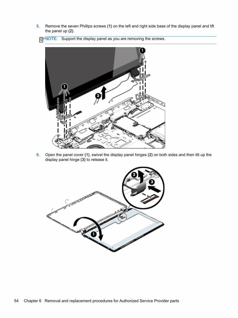
5. Remove the seven Phillips screws (1) on the left and right side base of the display panel and liftthe panel up (2).
NOTE: Support the display panel as you are removing the screws.
6. Open the panel cover (1), swivel the display panel hinges (2) on both sides and then tilt up thedisplay panel hinge (3) to release it.
54 Chapter 6 Removal and replacement procedures for Authorized Service Provider parts

7. Loosen the edges of the back cover (1), (2), and (3) from all four sides of the display bezel andlift the display panel (4).
NOTE: Use a sharp probe to pop the covers out to avoid scratching the bezel.
8. If you need to remove the panel, the display cable or the webcamera, follow these procedures.To remove the raw panel, remove the six Phillips screws (1) and any adhesive that secures thedisplay panel to the back cover and lift the display panel (2) carefully.
NOTE: Depending on your specific model, some computers only have four display panelscrews.
Component replacement procedures 55

9. Remove the display panel side bracket (select models only) by removing the four Phillips screws(1) and releasing the side bracket (2).
NOTE: If your computer model does not have side brackets, skip to the next step.
10. If it is necessary to remove the display panel cable or access the webcamera and microphone,follow these steps. With the display bezel upside down, disconnect the cable from thewebcamera/microphone (1) and from the routing channel built into the back cover.
Carefully release the cable from the channel guides, the guides in the display hinge, and removethe display panel cable (2). Lift the cable (3) to remove it.
56 Chapter 6 Removal and replacement procedures for Authorized Service Provider parts

11. On select models, removing the cable also requires disengaging it from the channels in thehinges and disconnecting from the display panel. To disconnect the cable from the displaypanel, carefully remove the foil tape at the bottom of the display panel and then carefully lift thedisplay cable connector (1) and remove the display connector (2).
12. If it is necessary to replace the webcamera/microphone perform the following: Lift the module (1)from the adhesive holding it in place on the display bezel and disconnect the module connector(2) if you have not already done so when removing the display cable.
13. If it is necessary to replace the WLAN antenna cable, follow these procedures:
a. Position the display back cover face up.
Component replacement procedures 57

b. Remove the display brackets by removing the eight Phillips and broadhead screws (1)securing the hinge brackets to the back cover, and then lift the brackets (2) to removethem.
c. Release the wireless antenna transceivers (1) from the display bezel. (The wirelessantenna transceivers are attached to the display bezel with double-sided tape.)
d. Remove the wireless antenna from the retaining channels (2), and lift the antenna (3).
Reverse this procedure to install the display panel.
58 Chapter 6 Removal and replacement procedures for Authorized Service Provider parts

WLAN module
Description Spare part number
Intel Dual Band Wireless-AC 3160 802.11 ac 1x1 WiFi + BT 4.0 combo adapter for use only withHP ENVY 17 Notebook PC computer models or HP ENVY 15 Notebook PC computer models
710662-005
Qualcomm Atheros AR9485 802.11 bgn 1x1 Wi-Fi adapter for use only with HP ENVY 17Notebook PC computer models or HP ENVY 15 Notebook PC computer models available forWindows 8.1 and Windows 7
675794-005
Intel Dual Band Wireless-AC 7260 802.11 ac 2x2 WiFi + BT 4.0 Combo Adapter non-Vproversion w/ dual antennas for use with HP ENVY 17 Notebook PC computer models only forWindows 8.1 and Windows 7
756753-005
CAUTION: To prevent an unresponsive system, replace the wireless module only with a wirelessmodule authorized for use in the computer by the governmental agency that regulates wirelessdevices in your country or region. If you replace the module and then receive a warning message,remove the module to restore device functionality, and then contact technical support.
Before removing the WLAN module, follow these steps:
1. Shut down the computer. If you are unsure whether the computer is off or in Hibernation, turnthe computer on, and then shut it down through the operating system.
2. Disconnect all external devices connected to the computer.
3. Disconnect the power from the computer by first unplugging the power cord from the AC outletand then unplugging the AC adapter from the computer.
4. Remove the battery (see Battery on page 42).
5. Remove the optical drive (see Optical drive on page 43).
6. Remove the base enclosure and top cover (see Base enclosure on page 46).
Remove the WLAN module:
1. Disconnect the #1 and #2 WLAN antenna cables from the WLAN module (1) if you have notalready done so to remove the display panel..
NOTE: The WLAN module may have two screws depending on the model.
NOTE: The #1 WLAN antenna cable is connected to the WLAN module #1 main terminal. The#2 WLAN antenna cable is connected to the WLAN module #2 auxiliary terminal.
2. Remove the Phillips screw(s) (2) that secure the WLAN module to the system board. (TheWLAN module tilts up.)
Component replacement procedures 59

3. Remove the WLAN module by pulling the module away from the slot at an angle (3).
NOTE: If the WLAN antennas are not connected to the terminals on the WLAN module, theprotective sleeves must be installed on the antenna connectors, as shown in the followingillustration.
60 Chapter 6 Removal and replacement procedures for Authorized Service Provider parts

TouchPad button board
Description
NOTE: Some models have the touchpad button board spared with the top cover. Removal isonly required on select models.
Spare part number
TouchPad button board (includes cable) for use with HP ENVY 15 Notebook PC computermodels
763790-001
TouchPad button board (includes cable) for use with HP ENVY 17 Notebook PC computermodels
763712-001
Before removing the TouchPad button board, follow these steps:
1. Shut down the computer. If you are unsure whether the computer is off or in Hibernation, turnthe computer on, and then shut it down through the operating system.
2. Disconnect all external devices connected to the computer.
3. Disconnect the power from the computer by first unplugging the power cord from the AC outletand then unplugging the AC adapter from the computer.
4. Remove the battery (see Battery on page 42).
5. Remove the optical drive (see Optical drive on page 43).
6. Remove the top cover from the base enclosure (see Base enclosure on page 46).
Remove the TouchPad button board:
1. Turn the top cover upside down, with the front toward you.
2. Remove the two broadhead screws (1) that secure the TouchPad button board bracket to thetop cover.
NOTE: Some models may have three broadhead screws for the TouchPad button board (1).
3. Remove the TouchPad board by carefully pushing the TouchPad down (2) and routing the cablethrough the opening (3) (the cable was disconnected earlier from the top cover).
Component replacement procedures 61

Reverse this procedure to install the TouchPad button board.
Battery Board (select models only)
Description Spare part number
Battery board for HP ENVY 17 Notebook PC 763710-001
The battery board is for select HP ENVY 17 Notebook PC computer models.
Before removing the battery board, follow these steps:
1. Disconnect all external devices connected to the computer.
2. Disconnect the power from the computer by first unplugging the power cord from the AC outletand then unplugging the AC adapter from the computer.
3. Remove the battery (see Battery on page 42).
4. Remove the optical drive (see Optical drive on page 43).
5. Remove the base enclosure and top cover (see Base enclosure on page 46).
Remove the battery board:
1. Turn the computer, with the front edge toward you.
2. Remove the two Phillips screws (1).
3. Lift the battery board (2) to remove it.
Reverse this procedure to install the battery board.
Optical drive connectorNOTE: The optical drive connector and cable are included in the optical drive spare part kit. (SeeOptical drive on page 43 for the spare part kit information.)
Before removing the optical drive connector board, follow these steps:
62 Chapter 6 Removal and replacement procedures for Authorized Service Provider parts

1. Shut down the computer. If you are unsure whether the computer is off or in Hibernation, turnthe computer on, and then shut it down through the operating system.
2. Disconnect all external devices connected to the computer.
3. Disconnect the power from the computer by first unplugging the power cord from the AC outletand then unplugging the AC adapter from the computer.
4. Remove the battery (see Battery on page 42).
5. Remove the optical drive (see Optical drive on page 43).
6. Remove the base enclosure and top cover (see Base enclosure on page 46).
Remove the optical drive connector board:
▲ Disconnect the cable from the ZIF connector (1), and then disconnect the optical drive connector(2) from the tabs to remove it.
Reverse this procedure to install the optical drive connector board.
Subwoofer
Description Spare part number
Subwoofer for HP ENVY 17 Notebook PC computer models 763716-001
Subwoofer for HP ENVY 15 Notebook PC computer models 763788-001
Before removing the subwoofer, follow these steps:
1. Shut down the computer. If you are unsure whether the computer is off or in Hibernation, turnthe computer on, and then shut it down through the operating system.
2. Disconnect all external devices connected to the computer.
3. Disconnect the power from the computer by first unplugging the power cord from the AC outletand then unplugging the AC adapter from the computer.
4. Remove the battery (see Battery on page 42).
Component replacement procedures 63

5. Remove the optical drive (see Optical drive on page 43).
6. Remove the base enclosure and top cover (see Base enclosure on page 46).
Remove the subwoofer:
▲ Disconnect the subwoofer cable (1) from the system board, remove the three Phillips screws (2),and then remove the subwoofer (3) by lifting it straight up.
NOTE: Carefully disconnect the cable by grasping the sides of the connector. Do not pull fromthe cables.
Reverse this procedure to install the subwoofer.
64 Chapter 6 Removal and replacement procedures for Authorized Service Provider parts

USB board
Description Spare part number
USB board for use with HP ENVY 17 Notebook PC computer models 763709-001
USB board for use with HP ENVY 15 Notebook PC computer models 763786-001
Before removing the USB board, follow these steps:
1. Shut down the computer. If you are unsure whether the computer is off or in Hibernation, turnthe computer on, and then shut it down through the operating system.
2. Disconnect all external devices connected to the computer.
3. Disconnect the power from the computer by first unplugging the power cord from the AC outletand then unplugging the AC adapter from the computer.
4. Remove the battery (see Battery on page 42).
5. Remove the optical drive (see Optical drive on page 43).
6. Remove the base enclosure and top cover (see Base enclosure on page 46).
Remove the USB board and cables:
1. Disconnect the USB cable from the ZIF connector (1).
2. Remove the Phillips screw securing the USB board (2), and lift the USB board (3) to remove it.
Reverse this procedure to install the USB board and cables.
Component replacement procedures 65

Hard drive
Description Spare part number
1.5 TB 5400-RPM SATA RAW 9.5 mm 747375-005
1-TB, 5400-RPM 778192-005
1-TB, 5400-RPM hybrid 731999-005
750-GB, 5400-RPM 778190-005
750-GB, 5400-RPM hybrid 732001-005
500 GB, 5400-RPM for use with HP ENVY 15 Notebook PC computer models 778188-005
Hard Drive Hardware Kit for use with HP ENVY 15 Notebook PC computer models 762504-001
Hard Drive Hardware Kit for use with HP ENVY 17 Notebook PC computer models 763705-001
Before removing the primary hard drive or secondary hard drive (select models only), follow thesesteps:
1. Shut down the computer. If you are unsure whether the computer is off or in Hibernation, turnthe computer on, and then shut it down through the operating system.
2. Disconnect all external devices connected to the computer.
3. Disconnect the power from the computer by first unplugging the power cord from the AC outletand then unplugging the AC adapter from the computer.
4. Remove the battery (see Battery on page 42).
5. Remove the optical drive (see Optical drive on page 43).
6. Remove the base enclosure and top cover (see Base enclosure on page 46).
7. Remove the USB connector board (see USB board on page 65).
Remove the primary hard drive:
▲ Disconnect the hard drive cable from the system board (1), and then tilt the hard drive (2) and liftto remove it (3).
66 Chapter 6 Removal and replacement procedures for Authorized Service Provider parts

If it is necessary to disassemble the hard drive:
▲ Remove the hard drive cable (1), and then remove the hard drive bracket (2).
Reverse these procedures to reassemble and install the hard drive.
System boardNOTE: The system board spare part kit includes replacement thermal material.
Description Spare part number
For use with HP ENVY 17 Computer models:
System board Intel Dual Core i7-4510U (2.0–GHz, SC turbo up to 3.1–GHz), processor(1600MHz/4 MB L3, 15W) discrete memory, and the Linux Ubuntu and FreeDos operatingsystem for HP ENVY 17 Notebook PC computer models
763721-001
Intel Dual Core i7-4510U (2.0–GHz, SC turbo up to 3.1–GHz), processor (1600MHz/4 MB L3,15W) discrete memory, and the Windows 8 Standard operating system
763721-501
Intel Dual Core i7-4510U (2.0–GHz, SC turbo up to 3.1–GHz), processor (1600MHz/4 MB L3,15W) discrete memory, and the Windows 8 Professional operating system
763721-601
Component replacement procedures 67

Description Spare part number
Intel Dual Core i7-4510U 850M 4 GB (2.0–GHz, SC turbo up to 3.1–GHz), processor (1600MHz/4 MB L3, 15W) discrete memory, and the Windows 8 Professional operating system
763727-501
Intel Dual Core i7-4510U 850M 4GB (2.0–GHz, SC turbo up to 3.1–GHz), processor (1600MHz/4MB L3, 15W) discrete memory, and the Windows 8 Professional operating system
763727-601
Intel Dual Core i5-4210U 840M 2 GB 1.7-GHz (SC turbo up to 2.7-GHz) processor (1600- MHz,3.0 MB L3 cache, 15 W) discrete memory, and the Windows 8 Standard operating system
763730-501
Intel Dual Core i5-4210U 840M 2 GB 1.7-GHz (SC turbo up to 2.7-GHz) processor (1600- MHz,3.0 MB L3 cache, 15 W) discrete memory, and the Windows 8 Professional operating system
763730-601
Intel Quad Core i7-4710HQ 2.50-GHz (SC turbo up to 3.50-GHz) processor (1600-MHz, 6.0 MBL3 cache, 47 W) UMA memory, and the Windows 8 Standard operating system
773128-501
Intel Quad Core i7-4710HQ 2.50-GHz (SC turbo up to 3.50-GHz) processor (1600-MHz, 6.0- MBL3 cache, 47 W) UMA memory, and the Windows 8 Professional operating system
773128-601
For use with HP ENVY 15 Computer models:
Intel Quad Core HM87 i7-4710HQ 2.50-GHz (SC turbo up to 3.50-GHz) processor (1600- MHz,6.0 MB L3 cache, 47 W) UMA memory
763585-001
Intel Quad Core HM87 i7-4710HQ 2.50-GHz (SC turbo up to 3.50-GHz) processor (1600- MHz,6.0 MB L3 cache, 47 W) UMA memory, and the Windows 8 Standard operating system.
763585-501
Intel Quad Core HM87 i7-4710HQ 2.50-GHz (SC turbo up to 3.50-GHz) processor (1600- MHz,6.0 MB L3 cache, 47 W) UMA memory , and the Windows 8 Professional and Windows 7 Prooperating system
763585-601
Intel Dual Core i5-4210U 840M 2 GB 1.7-GHz (SC turbo up to 2.7-GHz) processor (1600- MHz,3.0 MB L3 cache, 15 W) UMA memory
763586-001
Intel Dual Core i5-4210U 840M 2 GB 1.7-GHz (SC turbo up to 2.7-GHz) processor (1600- MHz,3.0 MB L3 cache, 15 W) UMA memory, and the Windows 8 Standard operating system
763586-501
Intel Dual Core i5-4210 U 840M 2 GB 1.7-GHz (SC turbo up to 2.7-GHz) processor (1600- MHz,3.0 MB L3 cache, 15 W) UMA memory, and the Windows 8 Professional operating system
763586-601
Intel Dual Core i7-4510U (2.0–GHz, SC turbo up to 3.1–GHz), processor (1600MHz/4 MB L3,15W) UMA memory
763587-001
Intel Dual Core i7-4510U (2.0–GHz, SC turbo up to 3.1–GHz), processor (1600MHz/4 MB L3,15W) UMA memory, and the Windows 8 Standard operating system
763587-501
Intel Dual Core i7-4510U (2.0–GHz, SC turbo up to 3.1–GHz), processor (1600MHz/4 MB L3,15W) UMA memory, and the Windows 8 Professional operating system and Windows 7 Pro
763587-601
Intel Dual Core i5-4210U 840M 2 GB 1.7-GHz (SC turbo up to 2.7-GHz) processor (1600- MHz,3.0 MB L3 cache, 15 W) discrete memory
763588-001
Intel Dual Core i5-4210U 840M 2 GB 1.7-GHz (SC turbo up to 2.7-GHz) processor (1600- MHz,3. MB L3 cache, 15 W) discrete memory, and the Windows 8 Standard operating system
763588-501
Intel Dual Core i5-4210U 840M 2 GB 1.7-GHz (SC turbo up to 2.7-GHz) processor (1600- MHz,3.0 MB L3 cache, 15 W) discrete memory, and the Windows 8 Professional operating system
763588-601
Intel Quad Core 840M i7-4710HQ 2.50-GHz (SC turbo up to 3.50-GHz) processor (1600- MHz,6.0 MB L3 cache, 47 W) discrete memory
766592-001
Intel Quad Core 840M i7-4710HQ 2.50-GHz (SC turbo up to 3.50-GHz) processor (1600- MHz,6.0 MB L3 cache, 47 W) discrete memory, and the Windows 8 Standard operating system
766592-501
Intel Quad Core 840M i7-4710HQ 2.50-GHz (SC turbo up to 3.50-GHz) processor (1600- MHz,6.0 MB L3 cache, 47 W) discrete memory, and the Windows 8 Professional and Windows 7 Prooperating system
766592-601
68 Chapter 6 Removal and replacement procedures for Authorized Service Provider parts

Before removing the system board, follow these steps:
1. Shut down the computer. If you are unsure whether the computer is off or in Hibernation, turnthe computer on, and then shut it down through the operating system.
2. Disconnect all external devices connected to the computer.
3. Disconnect the power from the computer by first unplugging the power cord from the AC outletand then unplugging the AC adapter from the computer.
4. Remove the battery (see Battery on page 42),
5. Remove the optical drive (see Optical drive on page 43).
6. Remove the top cover from the base enclosure (see Base enclosure on page 46).
7. Remove the WLAN module (see WLAN module on page 59).
8. Remove the subwoofer (see Subwoofer on page 63).
Remove the system board:
1. Remove the following cables if you have not already done so:
● Power connector board cable (1)
● Display cables (2), and (3)
● Speaker cable (4)
2. Disconnect the following cables if you have not already done so:
● Subwoofer cable (1)
● Optical drive cable (2)
● Hard drive cable (3)
● USB connector cable (4)
Component replacement procedures 69

3. Remove the power connector cover by removing the screw (1) and lifting the cover (2).
NOTE: The power connector cover has two Phillips screws, however, the screw on the left isremoved during the base enclosure and top cover removal process.
NOTE: You will remove the power connector after you have removed the system board. Thisprocedure is to remove the power connector cover if you did not remove it when removing thedisplay panel.
4. Remove the six Phillips screws (1).
70 Chapter 6 Removal and replacement procedures for Authorized Service Provider parts

5. Lift the system board (2), and then remove the system board (3) by sliding it up and to the rightat an angle.
Reverse this procedure to install the system board.
Speakers
Description Spare part number
Speaker Kit (includes left and right front speakers and cables) for HP ENVY 17 Notebook PCcomputer models
763717-001
Speaker Kit (includes left and right front speakers and cables) for HP ENVY 15 Notebook PCcomputer models
762502-001
Before removing the speakers, follow these steps:
Before removing the Speakers, follow these steps:
1. Shut down the computer. If you are unsure whether the computer is off or in Hibernation, turnthe computer on, and then shut it down through the operating system.
2. Disconnect all external devices connected to the computer.
3. Disconnect the power from the computer by first unplugging the power cord from the AC outletand then unplugging the AC adapter from the computer.
4. Remove the battery (see Battery on page 42),
5. Remove the optical drive (see Optical drive on page 43).
6. Remove the top cover from the base enclosure (see Base enclosure on page 46).
7. Remove the WLAN module (see WLAN module on page 59).
Component replacement procedures 71
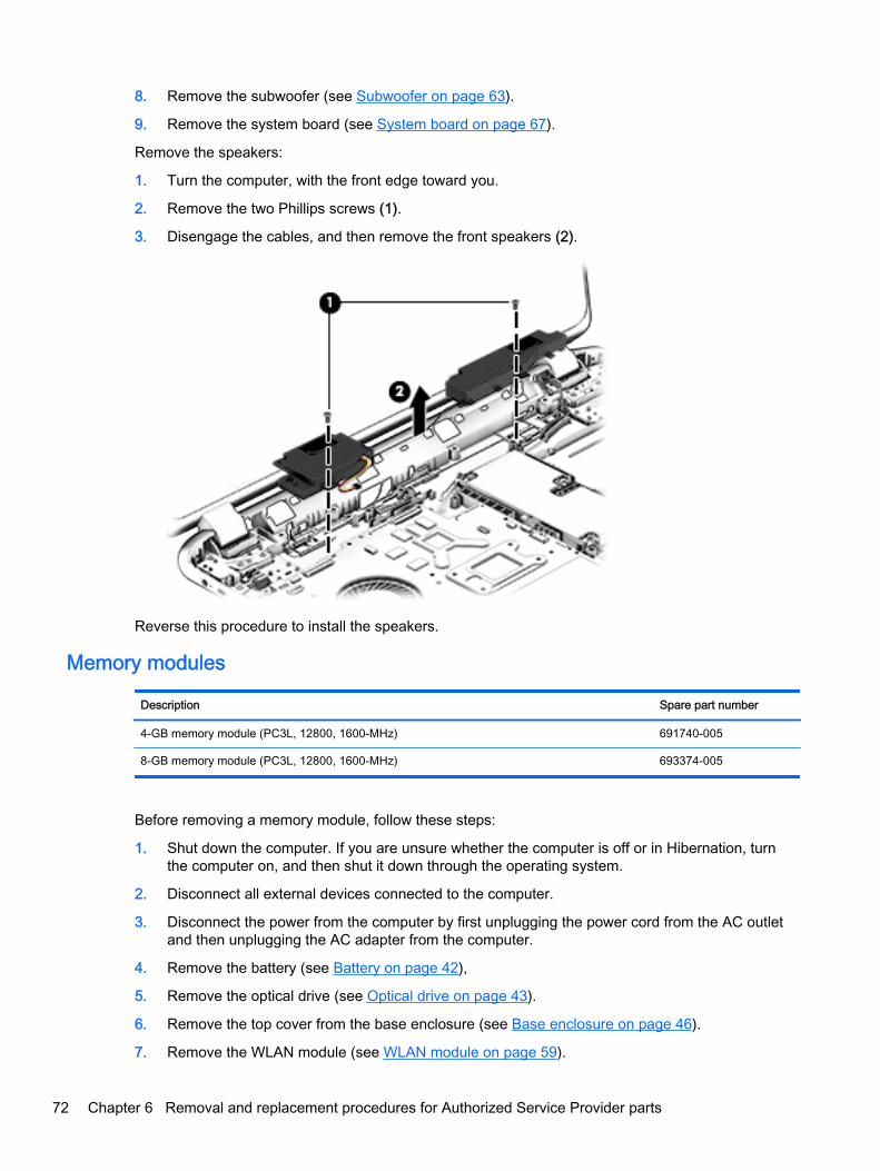
8. Remove the subwoofer (see Subwoofer on page 63).
9. Remove the system board (see System board on page 67).
Remove the speakers:
1. Turn the computer, with the front edge toward you.
2. Remove the two Phillips screws (1).
3. Disengage the cables, and then remove the front speakers (2).
Reverse this procedure to install the speakers.
Memory modules
Description Spare part number
4-GB memory module (PC3L, 12800, 1600-MHz) 691740-005
8-GB memory module (PC3L, 12800, 1600-MHz) 693374-005
Before removing a memory module, follow these steps:
1. Shut down the computer. If you are unsure whether the computer is off or in Hibernation, turnthe computer on, and then shut it down through the operating system.
2. Disconnect all external devices connected to the computer.
3. Disconnect the power from the computer by first unplugging the power cord from the AC outletand then unplugging the AC adapter from the computer.
4. Remove the battery (see Battery on page 42),
5. Remove the optical drive (see Optical drive on page 43).
6. Remove the top cover from the base enclosure (see Base enclosure on page 46).
7. Remove the WLAN module (see WLAN module on page 59).
72 Chapter 6 Removal and replacement procedures for Authorized Service Provider parts

8. Remove the subwoofer (see Subwoofer on page 63).
9. Remove the system board (see System board on page 67).
Remove the memory module:
1. Turn the system board over.
2. Spread the retaining tabs (1) on each side of the memory module slot to release thememory module. (The memory module tilts up.)
CAUTION: To prevent damage to the memory module, hold it by the edges only. Do not touchthe components on the memory module.
3. Slide the memory module forward (2) to remove it.
Reverse this procedure to install a memory module.
Component replacement procedures 73

RTC battery
Description Spare part number
RTC battery 697917-001
Before removing the RTC battery, follow these steps:
1. Shut down the computer. If you are unsure whether the computer is off or in Hibernation, turnthe computer on, and then shut it down through the operating system.
2. Disconnect all external devices connected to the computer.
3. Disconnect the power from the computer by first unplugging the power cord from the AC outletand then unplugging the AC adapter from the computer.
4. Remove the battery (see Battery on page 42),
5. Remove the optical drive (see Optical drive on page 43).
6. Remove the top cover from the base enclosure (see Base enclosure on page 46).
7. Remove the WLAN module (see WLAN module on page 59).
8. Remove the subwoofer (see Subwoofer on page 63).
9. Remove the system board (see System board on page 67).
Remove the RTC battery:
▲ Use a thin, non-conductive tool to remove the RTC battery (1) from the socket on the systemboard.
Reverse this procedure to install the RTC battery on computer models. When installing the RTCbattery, make sure the “+” sign faces up.
74 Chapter 6 Removal and replacement procedures for Authorized Service Provider parts

Fingerprint reader board (select models only)
Description Spare part number
Fingerprint reader board for use only on select HP ENVY 15 Computer Notebooks models 763789-001
Fingerprint reader board for use only on select HP ENVY 17 Computer Notebooks models 763711-001
Before removing the Fingerprint reader board, follow these steps:
1. Shut down the computer. If you are unsure whether the computer is off or in Hibernation, turnthe computer on, and then shut it down through the operating system.
2. Disconnect all external devices connected to the computer.
3. Disconnect the power from the computer by first unplugging the power cord from the AC outletand then unplugging the AC adapter from the computer.
4. Remove the battery (see Battery on page 42),
5. Remove the optical drive (see Optical drive on page 43).
6. Remove the top cover from the base enclosure (see Base enclosure on page 46).
7. Remove the WLAN module (see WLAN module on page 59).
8. Remove the subwoofer (see Subwoofer on page 63).
9. Remove the system board (see System board on page 67).
Remove the fingerprint reader board and cable:
1. Disconnect the ZIF connector cable (1) that secures the fingerprint reader to the top cover.
2. Release the top cover shield (2) and (3), and then remove the fingerprint reader board (4) bylifting the board.
Reverse this procedure to install the fingerprint reader board and cable.
Component replacement procedures 75

Power connector cable
Description Spare part number
For use only on computer models equipped with a graphics subsystem with discrete memory 720240-001
For use only on computer models equipped with a graphics subsystem with UMA memory 720241-001
Before removing the power connector, follow these steps:
1. Shut down the computer. If you are unsure whether the computer is off or in Hibernation, turnthe computer on, and then shut it down through the operating system.
2. Disconnect all external devices connected to the computer.
3. Disconnect the power from the computer by first unplugging the power cord from the AC outletand then unplugging the AC adapter from the computer.
4. Remove the battery (see Battery on page 42),
5. Remove the optical drive (see Optical drive on page 43).
6. Remove the top cover from the base enclosure (see Base enclosure on page 46).
7. Remove the WLAN module (see WLAN module on page 59).
8. Remove the subwoofer (see Subwoofer on page 63).
9. Remove the system board (see System board on page 67).
Remove the power connector cable:
1. Release the metal clip to disconnect the power connector cable (1) from the system board.
2. Disengage the cable from the clips (2).
3. Release the clips (3), and then remove the power connector cable (4).
Reverse this procedure to install the power connector cable and bracket.
76 Chapter 6 Removal and replacement procedures for Authorized Service Provider parts

Fan
Description Spare part number
Fan (with foil) 720235-001
Before removing the fan, follow these steps:
1. Shut down the computer. If you are unsure whether the computer is off or in Hibernation, turnthe computer on, and then shut it down through the operating system.
2. Disconnect all external devices connected to the computer.
3. Disconnect the power from the computer by first unplugging the power cord from the AC outletand then unplugging the AC adapter from the computer.
4. Remove the battery (see Battery on page 42),
5. Remove the optical drive (see Optical drive on page 43).
6. Remove the top cover from the base enclosure (see Base enclosure on page 46).
7. Remove the WLAN module (see WLAN module on page 59).
8. Remove the subwoofer (see Subwoofer on page 63).
9. Remove the system board (see System board on page 67).
Remove the fan:
1. Disconnect the fan cable from the system board, and then remove the piece of tape that securesthe fan to the heat sink (1).
2. Remove the three Phillips screws securing the fan to the unit (2) and (3).
3. Lift the fan (4) to remove it.
Reverse this procedure to install the fan.
Component replacement procedures 77

Heat sink
Description Spare part number
For use with HP ENVY 15 Notebook PC computer models:
For use only on computer models with UMA memory 19 W 763701-001
For use only on computer models with UMA memory 47 W 763702-001
For use only on computer models with discrete memory 19 W 763703-001
For use only on computer models with discrete memory 35 W 763704-001
For use with HP ENVY 17 Notebook PC computer models:
For use only on computer models with UMA memory 19 W 763701-001
For use only on computer models with UMA memory 47 W 763702-001
For use only on computer models with discrete memory 19 W 763703-001
For use only on computer models with discrete memory 35 W 763704-001
NOTE: To properly ventilate the computer, allow at least 7.6 cm (3 in) of clearance on the left sideof the computer. The computer uses an electric fan for ventilation. The fan is controlled by atemperature sensor and is designed to turn on automatically when high temperature conditions exist.These conditions are affected by high external temperatures, system power consumption, powermanagement/battery conservation configurations, battery fast charging, and software requirements.Exhaust air is displaced through the ventilation grill located on the left side of the computer.
Before removing the heat sink, follow these steps:
1. Shut down the computer. If you are unsure whether the computer is off or in Hibernation, turnthe computer on, and then shut it down through the operating system.
2. Disconnect all external devices connected to the computer.
3. Disconnect the power from the computer by first unplugging the power cord from the AC outletand then unplugging the AC adapter from the computer.
4. Remove the battery (see Battery on page 42),
5. Remove the optical drive (see Optical drive on page 43).
6. Remove the top cover from the base enclosure (see Base enclosure on page 46).
7. Remove the WLAN module (see WLAN module on page 59).
8. Remove the subwoofer (see Subwoofer on page 63).
9. Remove the system board (see System board on page 67).
10. Remove the fan (see Fan on page 77).
Remove the heat sink:
▲ Loosen the seven captive screws in the order listed on the heat sink (1), and then remove theheat sink (2).
NOTE: The heat sink may vary by computer model and may have a different number ofscrews. The heat sink is marked with the order the screws should be removed in. Follow theorder shown.
78 Chapter 6 Removal and replacement procedures for Authorized Service Provider parts

NOTE: There is thermal paste between the heat sink and the processor.
Reverse this procedure to install the heat sink.
Component replacement procedures 79

Power button board
Description Spare part number
Power button board (includes cable) For HP ENVY 15 Notebook PC computer models 762496-001
Power button board (includes cable) For HP ENVY 17 Notebook PC computer models 763708-001
Before removing the Power button board, follow these steps:
1. Shut down the computer. If you are unsure whether the computer is off or in Hibernation, turnthe computer on, and then shut it down through the operating system.
2. Disconnect all external devices connected to the computer.
3. Disconnect the power from the computer by first unplugging the power cord from the AC outletand then unplugging the AC adapter from the computer.
4. Remove the battery (see Battery on page 42),
5. Remove the optical drive (see Optical drive on page 43).
6. Remove the top cover from the base enclosure (see Base enclosure on page 46).
7. Remove the WLAN module (see WLAN module on page 59).
8. Remove the subwoofer (see Subwoofer on page 63).
9. Remove the system board (see System board on page 67).
Remove the Power button board and cable:
1. Turn the top cover upside down, with the back edge toward you.
2. Remove the two Phillips screws securing the Power button board to the base enclosure (1).
3. Remove the Power button board (2).
Reverse this procedure to install the Power button board.
80 Chapter 6 Removal and replacement procedures for Authorized Service Provider parts

7 Windows – Using Setup Utility (BIOS) andHP PC Hardware Diagnostics (UEFI)
Setup Utility, or Basic Input/Output System (BIOS), controls communication between all the input andoutput devices on the system (such as disk drives, display, keyboard, mouse, and printer). SetupUtility (BIOS) includes settings for the types of devices installed, the startup sequence of thecomputer, and the amount of system and extended memory.
Starting Setup Utility (BIOS)To start Setup Utility (BIOS), turn on or restart the computer, quickly press esc, and then press f10.
NOTE: Use extreme care when making changes in Setup Utility (BIOS). Errors can prevent thecomputer from operating properly.
Updating the BIOSUpdated versions of the BIOS may be available on the HP website.
Most BIOS updates on the HP website are packaged in compressed files called SoftPaqs.
Some download packages contain a file named Readme.txt, which contains information regardinginstalling and troubleshooting the file.
Determining the BIOS versionTo determine whether available BIOS updates contain later BIOS versions than those currentlyinstalled on the computer, you need to know the version of the system BIOS currently installed.
BIOS version information (also known as ROM date and System BIOS) can be revealed by pressingfn+esc (if you are already in Windows) or by using Setup Utility (BIOS).
1. Start Setup Utility (BIOS) (see Starting Setup Utility (BIOS) on page 81).
2. Use the arrow keys to select Main.
3. To exit Setup Utility (BIOS) without saving your changes, use the arrow keys to select Exit,select Exit Discarding Changes, and then press enter.
4. Select Yes.
Starting Setup Utility (BIOS) 81

Downloading a BIOS updateCAUTION: To reduce the risk of damage to the computer or an unsuccessful installation, downloadand install a BIOS update only when the computer is connected to reliable external power using theAC adapter. Do not download or install a BIOS update while the computer is running on batterypower, docked in an optional docking device, or connected to an optional power source. During thedownload and installation, follow these instructions:
Do not disconnect power from the computer by unplugging the power cord from the AC outlet.
Do not shut down the computer or initiate Sleep.
Do not insert, remove, connect, or disconnect any device, cable, or cord.
1. From the Start screen, type hp support assistant, and then select the HP SupportAssistant app.
For Windows 7, select Start > Help and Support > Maintain and go to Step 3 below.
2. Click Updates and tune-ups, and then click Check for HP updates now.
3. Follow the on-screen instructions.
4. At the download area, follow these steps:
a. Identify the most recent BIOS update and compare it to the BIOS version currently installedon your computer. If the update is more recent than your BIOS, make a note of the date,name, or other identifier. You may need this information to locate the update later, after ithas been downloaded to your hard drive.
b. Follow the on-screen instructions to download your selection to the hard drive.
If the update is more recent than your BIOS, make a note of the path to the location on yourhard drive where the BIOS update is downloaded. You will need to access this path whenyou are ready to install the update.
NOTE: If you connect your computer to a network, consult the network administrator beforeinstalling any software updates, especially system BIOS updates.
BIOS installation procedures vary. Follow any instructions that are revealed on the screen after thedownload is complete. If no instructions are revealed, follow these steps:
1. From the Start screen, type file, and then select File Explorer.
For Windows 7, open Windows Explorer by selecting Start > Computer.
2. Click your hard drive designation. The hard drive designation is typically Local Disk (C:).
3. Using the hard drive path you recorded earlier, open the folder on your hard drive that containsthe update.
4. Double-click the file that has an .exe extension (for example, filename.exe).
The BIOS installation begins.
5. Complete the installation by following the on-screen instructions.
NOTE: After a message on the screen reports a successful installation, you can delete thedownloaded file from your hard drive.
82 Chapter 7 Windows – Using Setup Utility (BIOS) and HP PC Hardware Diagnostics (UEFI)

Using HP PC Hardware Diagnostics (UEFI)HP PC Hardware Diagnostics is a Unified Extensible Firmware Interface (UEFI) that allows you to rundiagnostic tests to determine whether the computer hardware is functioning properly. The tool runsoutside the operating system so that it can isolate hardware failures from issues that are caused bythe operating system or other software components.
To start HP PC Hardware Diagnostics UEFI:
1. Turn on or restart the computer, quickly press esc, and then press f2.
The BIOS searches three places for the diagnostic tools, in the following order:
a. Connected USB drive
NOTE: To download the HP PC Hardware Diagnostics (UEFI) tool to a USB drive, seeDownloading HP PC Hardware Diagnostics (UEFI) to a USB device on page 83.
b. Hard drive
c. BIOS
2. When the diagnostic tool opens, use the keyboard arrow keys to select the type of diagnostictest you want to run, and then follow the on-screen instructions.
NOTE: If you need to stop a diagnostic test, press esc.
Downloading HP PC Hardware Diagnostics (UEFI) to a USB deviceNOTE: Instructions for downloading HP PC Hardware Diagnostics (UEFI) are provided in Englishonly.
There are two options to download HP PC Hardware Diagnostics to a USB device:
Option 1: HP PC Diagnostics homepage— Provides access to the latest UEFI version
1. Go to http://hp.com/go/techcenter/pcdiags.
2. Click the UEFI Download link, and then select Run.
Option 2: Support and Drivers page—Provides downloads for a specific product for earlier and laterversions
1. Go to http://www.hp.com.
2. Point to Support, located at the top of the page, and then click Download Drivers.
3. In the text box, enter the product name, and then click Go.
– or –
Click Find Now to let HP automatically detect your product.
4. Select your computer model, and then select your operating system.
5. In the Diagnostic section, click HP UEFI Support Environment.
– or –
Click Download, and then select Run.
Using HP PC Hardware Diagnostics (UEFI) 83

8 Windows 7 Backing up, restoring, andrecovering
Your computer includes tools provided by the operating system and HP to help you safeguard yourinformation and retrieve it if ever needed.
Creating backups1. Use HP Recovery Manager to create recovery media immediately after you set up the working
computer.
2. As you add hardware and software programs, create system restore points.
3. As you add photos, video, music, and other personal files, create a backup of your system andpersonal information.
Creating recovery media to recover the original systemAfter you successfully set up the computer, you should create recovery discs or a recovery flash driveusing HP Recovery Manager. You will need these recovery discs or recovery flash drive to perform asystem recovery should the hard drive become corrupted. A system recovery reinstalls the originaloperating system, and then configures the settings for the default programs.
What you need to know● Only one set of recovery media can be created. Handle these recovery tools carefully, and keep
them in a safe place.
● HP Recovery Manager examines the computer and determines the required storage capacity forthe flash drive or the number of blank DVD discs that will be required.
Use DVD-R, DVD+R, DVD-R DL, DVD+R DL discs or a flash drive. Do not use rewriteable discssuch as CD±RW, DVD±RW, double-layer DVD±RW, and BD-RE (rewritable Blu-ray) discs; theyare not compatible with HP Recovery Manager software.
● If your computer does not include an integrated optical drive, you can use an optional externaloptical drive (purchased separately) to create recovery discs, or you can obtain recovery discsfor your computer from the HP website. If you use an external optical drive, it must be connecteddirectly to a USB port on the computer, not to a USB port on an external device, such as a USBhub.
● Be sure that the computer is connected to AC power before you begin creating the recoverymedia.
● The creation process can take up to an hour or more. Do not interrupt the creation process.
● Store the recovery media in a safe location, separate from the computer.
● If necessary, you can exit the program before you have finished creating the recovery media.The next time you open HP Recovery Manager, you will be prompted to continue the process.
84 Chapter 8 Windows 7 Backing up, restoring, and recovering

Creating the recovery media
1. Select Start and type recovery in the search field. Select Recovery Manager from the list.Allow the action to continue, if prompted.
2. Click Recovery Media Creation.
3. Follow the on-screen instructions to continue.
To recover, see Recovering the original system using HP Recovery Manager on page 87.
Creating system restore pointsA system restore point is a snapshot of certain hard drive contents saved by Windows SystemRestore at a specific time. A restore point contains information such as registry settings that Windowsuses. Restoring to a previous restore point allows you to reverse changes that have been made to thesystem since the restore point was created.
Restoring to an earlier system restore point does not affect data files saved or emails created sincethe last restore point, but it does affect software you may have installed.
For example, if you download a photo from a digital camera and then restore the computer to thestate it was on the previous day, the photo remains on the computer.
However, if you install photo viewing software and then restore your computer to the state it was onthe previous day, the software will be uninstalled, and you won't be able to use it.
What you need to know● If you restore to a restore point and then change your mind, you can undo the restoration.
● You should create system restore points:
◦ Before you add or change software or hardware
◦ Periodically, whenever the computer is running normally
● System Restore also saves shadow copies of files that have been changed since the last restorepoint was created. For more information about using shadow copies to restore, see Help andSupport.
Creating a system restore point1. Select Start > Control Panel > System and Security > System.
2. In the left pane, click System Protection.
3. Click the System Protection tab.
4. Click Create, and follow the on-screen instructions.
To restore, see Restoring to a previous system restore point on page 87.
Backing up system and personal informationYour computer stores information that is important to you, such as files, emails, and photos, and youwill want to keep that information even if you download a virus or the system stops working properly.How completely you are able to recover your files depends on how recent your backup is. As you addnew software and data files, you should create backups on a regular basis.
Creating backups 85

Tips for a successful backup● Number backup discs before inserting them into the optical drive.
● Store personal files in the Documents, Music, Pictures, and Videos libraries, and back up thesefolders periodically.
● Save customized settings in a window, toolbar, or menu bar by taking a screen shot of yoursettings. The screen shot can be a time-saver if you have to re-enter your preferences.
To create a screen shot:
1. Display the screen you want to save.
2. Copy the screen image:
To copy only the active window, press alt+prt sc.
To copy the entire screen, press prt sc.
3. Open a word-processing document or graphics editing program, and then select Edit > Paste.The screen image is added to the document.
4. Save and print the document.
What you need to know● You can back up your information to an optional external hard drive, a flash drive, a network
drive, or discs.
● Connect the computer to AC power during backups.
● Allow enough time for the backup. Depending on files sizes, it may take more than an hour.
● Verify the amount of free space on your backup storage device before you back up.
● You should back up:
◦ Before adding or changing software or hardware.
◦ Before the computer is repaired or restored.
◦ On a regular schedule to be sure you have recent copies of personal information.
◦ After you add many files—for example, if you saved videos from a birthday party.
◦ Before using antivirus software to remove a malicious program.
◦ After adding information that is hard to replace, such as pictures, videos, music, projectfiles, or data records.
Creating a backup using Windows Backup and RestoreWindows allows you to back up files using Windows Backup and Restore. You can select the levelyou want to back up, from individual folders to drives. The backups are compressed to save space.To back up:
1. Select Start > Control Panel > System and Security > Backup and Restore.
2. Follow the on-screen instructions to schedule and create a backup.
NOTE: Windows includes the User Account Control feature to improve the security of the computer.You may be prompted for your permission or password for tasks such as installing software, runningutilities, or changing Windows settings. See Help and Support for more information.
86 Chapter 8 Windows 7 Backing up, restoring, and recovering

To restore, see Restoring specific files using Windows Backup and Restore on page 87.
Restore and recovery
Restoring to a previous system restore pointSometimes installing a software program causes your computer or Windows to behave unpredictably.Usually uninstalling the software fixes the problems. If uninstalling does not fix the problems, you canrestore the computer to a previous system restore point (created at an earlier date and time).
To restore to a previous system restore point, when the computer was running correctly:
1. Select Start > Control Panel > System and Security > System.
2. In the left pane, click System Protection.
3. Click the System Protection tab.
4. Click System Restore, and follow the on-screen instructions.
Restoring specific filesIf files are accidentally deleted from the hard disk and they can no longer be restored from theRecycle Bin, or if files become corrupt, restoring specific files is useful. Restoring specific files is alsouseful if you ever choose to recover the original system using HP Recovery Manager. You can onlyrestore specific files that you have backed up before.
Restoring specific files using Windows Backup and RestoreWindows allows you to restore files that were backed up using Windows Backup and Restore:
1. Select Start > Control Panel > System and Security > Backup and Restore.
2. Follow the on-screen instructions to restore your backup.
NOTE: Windows includes the User Account Control feature to improve the security of the computer.You may be prompted for your permission or password for tasks such as installing software, runningutilities, or changing Windows settings. See Help and Support for more information.
Recovering the original system using HP Recovery ManagerHP Recovery Manager software allows you to repair or recover the computer to its original factorystate.
What you need to know● HP Recovery Manager recovers only software that was installed at the factory. For software not
provided with this computer, you must either download the software from the manufacturer'swebsite or reinstall the software from the disc provided by the manufacturer.
● A system recovery should be used as a final attempt to correct computer issues. If you have notalready tried restore points (see Restoring to a previous system restore point on page 87) andpartial restores (see Restoring specific files on page 87), try them before using HP RecoveryManager to recover your system.
● A system recovery must be performed if the computer hard drive fails or if all attempts to correctany functional computer issues fail.
Restore and recovery 87

● If the recovery media do not work, you can obtain recovery discs for your system from the HPwebsite.
● The Minimized Image Recovery option is recommended for advanced users only. All hardware-related drivers and software are re-installed, but other software applications are not. Do notinterrupt the process until it is complete, otherwise the recovery will fail.
Recovering using HP Recovery partition (select models only)The HP Recovery partition (select models only), allows you to restore your system without the needfor recovery discs or a recovery flash drive. This type of recovery can only be used if the hard drive isstill working.
To check for the presence of a recovery partition, select Start, right-click Computer then selectManage > Disk Management. If the recovery partition is present, a Recovery drive is listed in thewindow.
NOTE: Recovery discs have been included if your computer did not ship with a recovery partition.
1. Access HP Recovery Manager in either of the following ways:
● Select Start and type recovery in the search field. Select Recovery Manager from the list.
– or –
● Turn on or restart the computer, and then press esc while the “Press the ESC key forStartup Menu” message is displayed at the bottom of the screen. Then press f11 while the“F11 (System Recovery)” message is displayed on the screen.
2. Click System Recovery in the HP Recovery Manager window.
3. Follow the on-screen instructions.
Recovering using the recovery media1. If possible, back up all personal files.
2. Insert the first recovery disc into the optical drive on your computer or an optional externaloptical drive, and then restart the computer.
– or –
Insert the recovery flash drive into a USB port on your computer, and then restart the computer.
NOTE: If the computer does not automatically restart in HP Recovery Manager, change thecomputer boot order. See Changing the computer boot order on page 88.
3. Press f9 at system bootup.
4. Select the optical drive or the flash drive.
5. Follow the on-screen instructions.
Changing the computer boot order
To change the boot order for recovery discs:
1. Restart the computer.
2. Press esc while the computer is restarting, and then press f9 for boot options.
3. Select Internal CD/DVD ROM Drive from the boot options window.
88 Chapter 8 Windows 7 Backing up, restoring, and recovering

To change the boot order for a recovery flash drive:
1. Insert the flash drive into a USB port.
2. Restart the computer.
3. Press esc while the computer is restarting, and then press f9 for boot options.
4. Select the flash drive from the boot options window.
Restore and recovery 89

9 Windows 8.1 Backing up, restoring, andrecovering
Your computer includes tools provided by HP and Windows to help you safeguard your informationand retrieve it if you ever need to. These tools will help you return your computer to a proper workingstate or even back to the original factory state, all with simple steps.
This chapter provides information about the following processes:
● Creating recovery media and backups
● Restoring and recovering your system
NOTE: This chapter describes an overview of backing up, restoring and recovering options. Formore details about the tools provided, see Help and Support. From the Start screen, type help, andthen select Help and Support.
Creating recovery media and backups1. After you successfully set up the computer, create HP Recovery media. This step creates a
backup of the HP Recovery partition on the computer. The backup can be used to reinstall theoriginal operating system in cases where the hard drive is corrupted or has been replaced.
HP Recovery media you create will provide the following recovery options:
● System Recovery—Reinstalls the original operating system and the programs that wereinstalled at the factory.
● Minimized Image Recovery—Reinstalls the operating system and all hardware-relateddrivers and software, but not other software applications.
● Factory Reset—Restores the computer to the state its original factory state by deleting allinformation from the hard drive and re-creating the partitions. Then it reinstalls theoperating system and the software that was installed at the factory.
See Creating HP Recovery media on page 90.
2. Use the Windows tools to create system restore points and create backups of personalinformation. For more information and steps, see Windows Help and Support. From the Startscreen, type help, and then select Help and Support.
Creating HP Recovery mediaHP Recovery Manager is a software program that offers a way to create recovery media after yousuccessfully set up the computer. HP Recovery media can be used to perform system recovery if thehard drive becomes corrupted. System recovery reinstalls the original operating system and thesoftware programs installed at the factory, and then configures the settings for the programs. HPRecovery media can also be used to customize the system or restore the factory image if you replacethe hard drive.
90 Chapter 9 Windows 8.1 Backing up, restoring, and recovering

● Only one set of HP Recovery media can be created. Handle these recovery tools carefully, andkeep them in a safe place.
● HP Recovery Manager examines the computer and determines the required storage capacity forthe blank USB flash drive or the number of blank DVD discs that will be required.
● To create recovery discs, your computer must have an optical drive with DVD writer capability,and you must use only high-quality blank DVD-R, DVD+R, DVD-R DL, DVD+R DL discs. Do notuse rewritable discs such as CD±RW, DVD±RW, double-layer DVD±RW, or BD-RE (rewritableBlu-ray) discs; they are not compatible with HP Recovery Manager software. Or instead you canuse a high-quality blank USB flash drive.
● If your computer does not include an integrated optical drive with DVD writer capability, but youwould like to create DVD recovery media, you can use an external optical drive (purchasedseparately) to create recovery discs, or you can obtain recovery discs for your computer from theHP website. For U.S. support, go to http://www.hp.com/go/contactHP. For worldwide support, goto http://welcome.hp.com/country/us/en/wwcontact_us.html. If you use an external optical drive,it must be connected directly to a USB port on the computer; the drive cannot be connected to aUSB port on an external device, such as a USB hub.
● Be sure that the computer is connected to AC power before you begin creating the recoverymedia.
● The creation process can take up to an hour or more. Do not interrupt the creation process.
● If necessary, you can exit the program before you have finished creating all of the recoveryDVDs. HP Recovery Manager will finish burning the current DVD. The next time you start HPRecovery Manager, you will be prompted to continue, and the remaining discs will be burned.
To create HP Recovery media:
1. From the Start screen, type recovery, and then select HP Recovery Manager.
2. Select Recovery Media Creation, and follow the on-screen instructions to continue.
If you ever need to recover the system, see Recovering using HP Recovery Manager on page 92.
Restore and recoveryThere are several options for recovering your system. Choose the method that best matches yoursituation and level of expertise:
● Windows offers several options for restoring from backup, refreshing the computer, and resettingthe computer to its original state. For more information and steps, see Help and Support. Fromthe Start screen, type help, and then select Help and Support.
● If you need to correct a problem with a preinstalled application or driver, use the Drivers andApplications Reinstall option of HP Recovery Manager to reinstall the individual application ordriver.
From the Start screen, type recovery, select HP Recovery Manager, and then select Driversand Applications Reinstall, and follow the on-screen instructions.
● If you want to reset your computer using a minimized image, you can choose the HP MinimizedImage Recovery option from the HP Recovery partition or HP Recovery media. Minimized ImageRecovery installs only drivers and hardware-enabling applications. Other applications included inthe image continue to be available for installation through the Drivers and Applications Reinstalloption in HP Recovery Manager.
For more information, see Recovering using HP Recovery Manager on page 92.
Restore and recovery 91

● If you want to recover the computer's original factory partitioning and content, you can choosethe System Recovery option from the HP Recovery media. For more information, seeRecovering using HP Recovery Manager on page 92.
● If you have replaced the hard drive, you can use the Factory Reset option of HP Recoverymedia to restore the factory image to the replacement drive. For more information, seeRecovering using HP Recovery Manager on page 92.
● If you wish to remove the recovery partition to reclaim hard drive space, HP Recovery Manageroffers the Remove Recovery Partition option.
For more information, see Removing the HP Recovery partition on page 93.
Recovering using HP Recovery ManagerHP Recovery Manager software allows you to recover the computer to its original factory state. Usingthe HP Recovery media you created, you can choose from one of the following recovery options:
● System Recovery—Reinstalls the original operating system, and then configures the settings forthe programs that were installed at the factory.
● Minimized Image Recovery (select models only)—Reinstalls the operating system and allhardware-related drivers and software, but not other software applications.
● Factory Reset—Restores the computer to the state its original factory state by deleting allinformation from the hard drive and re-creating the partitions. Then it reinstalls the operatingsystem and the software that was installed at the factory.
The HP Recovery partition (select models only) allows System Recovery (on Windows 8.1 models)and Minimized Image Recovery.
What you need to know● HP Recovery Manager recovers only software that was installed at the factory. For software not
provided with this computer, you must either download the software from the manufacturer'swebsite or reinstall the software from the media provided by the manufacturer.
● Recovery through HP Recovery Manager should be used as a final attempt to correct computerissues.
● HP Recovery media must be used if the computer hard drive fails.
● To use the Factory Reset or System Recovery options, you must use HP Recovery media.
● If the HP Recovery media do not work, you can obtain recovery media for your system from theHP website. For U.S. support, go to http://www.hp.com/go/contactHP. For worldwide support, goto http://welcome.hp.com/country/us/en/wwcontact_us.html.
IMPORTANT: HP Recovery Manager does not automatically provide backups of your personaldata. Before beginning recovery, back up any personal data you wish to retain.
Using the HP Recovery partition (select models only) The HP Recovery partition allows you to perform a system recovery (on Windows 8.1 models) or aminimized image recovery without the need for recovery discs or a recovery USB flash drive. Thistype of recovery can only be used if the hard drive is still working.
To start HP Recovery Manager from the HP Recovery partition:
92 Chapter 9 Windows 8.1 Backing up, restoring, and recovering

1. Press f11 while the computer boots.
– or –
Press and hold f11 as you press the power button.
2. Select Troubleshoot from the boot options menu.
3. Select Recovery Manager, and follow the on-screen instructions.
Using HP Recovery media to recoverYou can use HP Recovery media to recover the original system. This method can be used if yoursystem does not have an HP Recovery partition or if the hard drive is not working properly.
1. If possible, back up all personal files.
2. Insert the first HP Recovery disc you created into the optical drive on your computer or into anoptional external optical drive, and then restart the computer.
– or –
Insert the HP Recovery USB flash drive you created into a USB port on your computer, and thenrestart the computer.
NOTE: If the computer does not automatically restart in HP Recovery Manager, change thecomputer boot order. See Changing the computer boot order on page 93.
3. Follow the on-screen instructions.
Changing the computer boot orderIf computer does not restart in HP Recovery Manager, you can change the computer boot order,which is the order of devices listed in BIOS where the computer looks for startup information. You canchange the selection for an optical drive or a USB flash drive.
To change the boot order:
1. Insert the HP Recovery media you created.
2. Restart the computer.
3. Press and hold esc while the computer is restarting, and then press f9 for boot options.
4. Select the optical drive or USB flash drive you want to boot from.
5. Follow the on-screen instructions.
Removing the HP Recovery partitionHP Recovery Manager software allows you to remove the HP Recovery partition to free up hard drivespace.
IMPORTANT: Removing the HP Recovery partition means you can no longer use WindowsRefresh, the Windows Remove everything and reinstall Windows option, or the HP RecoveryManager option for minimized image recovery. Create HP Recovery media before removing theRecovery partition to ensure you have recovery options; see Creating HP Recovery mediaon page 90.
Follow these steps to remove the HP Recovery partition:
Restore and recovery 93

1. From the Start screen, type recovery, and then select HP Recovery Manager.
2. Select Remove Recovery Partition, and follow the on-screen instructions to continue.
94 Chapter 9 Windows 8.1 Backing up, restoring, and recovering

10 Ubuntu Linux – Backing up, restoring, andrecovering
Recovery after a system failure is as good as your most recent backup. As you add new software anddata files, you should continue to back up your system on a regular basis to maintain a reasonablycurrent backup.
Performing a system recoveryThe Deja Dup Restore Tool allows you to repair or restore the computer to its original factory state.You can create an image restore DVD using an optional external DVD±RW optical drive. You canalso create a restore image on a USB storage device.
CAUTION: Using Restore completely erases hard drive contents and reformats the hard drive. Allfiles you have created and any software installed on the computer are permanently removed. Therecovery tool reinstalls the original operating system and programs and drivers that were installed atthe factory. Software, drivers, and updates not installed at the factory must be manually reinstalled.Personal files must be restored from a backup.
NOTE: HP recommends that you create the image restore in the event of a system failure.
Creating the restore DVDsThe restore creation software creates a set of system restore discs using blank, writable DVDs (DVD-R or DVD+R). HP recommends using blank DVD+R discs from a manufacturer you trust, becausethese recovery DVDs are so important. You need approximately 3 blank DVD+R discs. The programstates how many discs are needed at the beginning of the process.
To create restore DVDs:
1. Click the System menu icon at the far right of the top panel, and then click System Settings >Backup.
2. Select Storage from the panel on the left side of the window, click the down-arrow next toBackup Location, and select the DVD from the drop-down list.
3. Select Overview from the panel on the left side of the window, and then click Back Up Now.
4. Follow the on-screen instructions.
Creating a restore image on a USB deviceNOTE: Be sure AC power is connected to the computer you begin.
Verify the exact amount of free space on your storage device before you begin the creation process.For most models, you will need at least 8 GB of free space on the storage device. However,depending on the drivers and software installed on your computer, you may need slightly more than 8GB of space. HP recommends that you use a 16 GB device or above for best results.
IMPORTANT: Remember to insert your USB device into the USB port on the computer beforestarting this procedure.
Performing a system recovery 95

To create the restore image:
1. Click the System menu icon at the far right of the top panel, and then click System Settings >Backup.
2. Select Storage from the panel on the left side of the window, click the down-arrow next toBackup location, and select the USB device from the drop-down list.
NOTE: If the USB device is not listed in the drop-down list for Backup Location, select LocalFolder, and then click the Choose Folder button. Select the USB device from the panel on theleft side of the Choose Folder window, and click OK.
3. Select Overview from the panel on the left side of the window, and then click Backup Now.
4. Follow the on-screen instructions.
Performing recovery using the restore mediaNOTE: The following procedure uses the F11 BIOS Recovery feature to perform the recovery.
1. If possible, back up all personal files.
2. Shut down the computer.
3. Be sure the restore DVD or USB device is connected to the computer.
4. Restart the computer.
5. Using the arrow keys, select Recovery, and then press enter.
6. Follow the on-screen instructions.
NOTE: If you are unable to boot (start up) your computer with the primary operating system, andyou did not create a system recovery disc, you must purchase an Ubuntu Operating System DVD toreinstall the operating system. For additional information, refer to the Worldwide Telephone Numbersbooklet for more information.
Backing up your informationYou should back up your computer files on a regular schedule to maintain a current backup. You canmanually back up your information to an optional external drive, a network drive, discs, or the UbuntuOne website. Back up your system at the following times:
● At regularly scheduled times
● Before the computer is repaired or restored
● Before you add or modify hardware or software
To back up your home directory files to the Ubuntu website using the Deja Dup Backup Tool:
NOTE: Before you back up your information, be sure you have designated a location to save thebackup files.
1. Click the System menu icon at the far right of the top panel, and then click System Settings >Backup icon.
2. Select Folders from the panel on the left side of the window, and beneath Folders to back up,select the folders to back up.
96 Chapter 10 Ubuntu Linux – Backing up, restoring, and recovering

3. Select Storage from the panel on the left side of the window, click the down-arrow next toBackup Location, and select Ubuntu One from the drop-down list.
4. Select Overview from the panel on the left side of the window, and then click Back Up Now.
NOTE: The first time you backup your files to Ubuntu One, you will need to create an accountto sign into Ubuntu One. Enter your email address and password into the account sign-in boxesand follow the on-screen instructions to complete the sign-in process.
To restore backup files:
1. Click the System menu icon at the far right of the top panel, and then click System Settings >Backup icon.
2. Click Restore, select the location of the backup files and the folder name, and then clickForward.
3. Under Restore from When?, select the date of the files to be restored and click Forward.
4. Select the location and folder where the files are to be restored and click Forward.
5. Follow the on-line instructions.
6. Click Restore to start restoring the files, or click Cancel to cancel the operation.
NOTE: You may also back up to cloud storage services provided by various companies. For a smallfee, they will keep your backup for you. A cloud service is recommended since it is an easy way tokeep your backups off-site and safe from any disaster.
Backing up your information 97

11 Specifications
Computer specifications Metric U.S.
Dimensions (non-touch)
Width for HP Envy 17 Notebook PC
Width for HP Envy 15 Notebook PC
41.95 cm
38.45 cm
16.5 in
15.9 in
Depth for HP Envy 17 Notebook PC
Depth for HP Envy 15 Notebook PC
27.9 cm
26.09 cm
10.7 in
10.3 in
Height (front to back) for HP Envy 17 Notebook PC
Height (front to back) for HP Envy 15 Notebook PC
2.67 cm
2.49 cm
1.1 in
1 in
Weight
With 4-cell battery for HP Envy 17 Notebook PC
With 4-cell battery for HP Envy 15 Notebook PC
2.87 kg
2.34 kg
6.33 lbs
5.16 lbs
Input power
Operating voltage and current 19.5 V dc @ 3.33 A – 65 W
19.5 V dc @ 4.62 A – 90 W
19.5 V dc @ 2.31 A – 45 W
Temperature
Operating 5°C to 35°C 41°F to 95°F
Nonoperating ‑20°C to 60°C ‑4°F to 140°F
Relative humidity (noncondensing)
Operating 10% to 90%
Nonoperating 5% to 95%
Maximum altitude (unpressurized)
Operating ‑15 m to 3,048 m ‑50 ft to 10,000 ft
Nonoperating ‑15 m to 12,192 m ‑50 ft to 40,000 ft
NOTE: Applicable product safety standards specify thermal limits for plastic surfaces. The device operates well within thisrange of temperatures.
98 Chapter 11 Specifications

43.9-cm (17.3-in), HD+ display specifications Metric U.S.
Active diagonal size 43.9-cm 17.3-in
Resolution 1600x900 (HD+)
Active area 382.08x214.92
PPI 106
Surface treatment Anti-glare or BrightView
Contrast ratio 300:1 (typical) – Anti-glare
500:1 – BrightView
Response time 16 ms
Brightness 200 nits (typical)
Viewing angle SVA
Backlight LED
Luminance uniformity @ 13 points 1.4 (typ), 1.6 (max)
Lifetime (1/2 luminance) 12,000 hours
Color coordinate (white) (0.313, 0.329)
Color tolerance (White) +/- 0.02
Color tolerance (W, R, G, B) +/- 0.03
Color gamut 60% NTSC @ CIE 1931
43.9-cm (17.3-in), HD+ display specifications 99
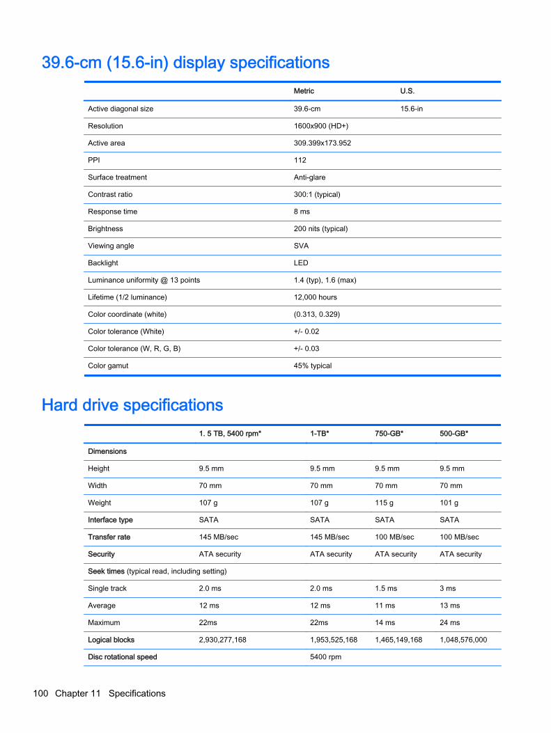
39.6-cm (15.6-in) display specifications Metric U.S.
Active diagonal size 39.6-cm 15.6-in
Resolution 1600x900 (HD+)
Active area 309.399x173.952
PPI 112
Surface treatment Anti-glare
Contrast ratio 300:1 (typical)
Response time 8 ms
Brightness 200 nits (typical)
Viewing angle SVA
Backlight LED
Luminance uniformity @ 13 points 1.4 (typ), 1.6 (max)
Lifetime (1/2 luminance) 12,000 hours
Color coordinate (white) (0.313, 0.329)
Color tolerance (White) +/- 0.02
Color tolerance (W, R, G, B) +/- 0.03
Color gamut 45% typical
Hard drive specifications 1. 5 TB, 5400 rpm* 1-TB* 750-GB* 500-GB*
Dimensions
Height 9.5 mm 9.5 mm 9.5 mm 9.5 mm
Width 70 mm 70 mm 70 mm 70 mm
Weight 107 g 107 g 115 g 101 g
Interface type SATA SATA SATA SATA
Transfer rate 145 MB/sec 145 MB/sec 100 MB/sec 100 MB/sec
Security ATA security ATA security ATA security ATA security
Seek times (typical read, including setting)
Single track 2.0 ms 2.0 ms 1.5 ms 3 ms
Average 12 ms 12 ms 11 ms 13 ms
Maximum 22ms 22ms 14 ms 24 ms
Logical blocks 2,930,277,168 1,953,525,168 1,465,149,168 1,048,576,000
Disc rotational speed 5400 rpm
100 Chapter 11 Specifications

1. 5 TB, 5400 rpm* 1-TB* 750-GB* 500-GB*
Operating temperature 5°C to 55°C (41°F to 131°F)
*1 TB = 1 trillion bytes and 1 GB = 1 billion bytes when referring to hard drive storage capacity. Actual accessible capacity isless. Actual drive specifications may differ slightly.
NOTE: Certain restrictions and exclusions apply. Contact technical support for details.
DVD±RW SuperMulti Double-Layer Combination Drivespecifications
Applicable disc
Read CD-DA, CD+(E)G, CD-MIDI, CD-TEXT, CD-ROM, CD-ROM XA, MIXEDMODE CD, CD-I, CD-I Bridge (Photo-CD, Video CD), Multisession CD(Photo-CD, CD-EXTRA, Portfolio, CD-R, CD-RW), CD-R, CD-RW, DVD-ROM (DVD-5, DVD-9, DVD-10, DVD-18), DVD-R, DVD-RW, DVD+R, DVD+RW, DVD-RAM
Write CD-R and CD-RW, DVD+R, DVD+RW, DVD-R, DVD-RW, DVD-RAM
Random access time
DVD < 230 ms
CD < 175 ms
Cache buffer 2 MB
Data transfer rate
24X CD-ROM 3,600 KB/sec
8X DVD-ROM 10,800 KB/sec
24X CD-R 3,600 KB/sec
16X CD-RW 2,400 KB/sec
8X DVD+R 10,800 KB/sec
4X DVD+RW 5,400 KB/sec
8X DVD-R 10,800 KB/sec
4X DVD-RW 5,400 KB/sec
2.4X DVD+R(9) 2,700 KB/sec
5X DVD-RAM 6,750 KB/sec
Transfer mode Multiword DMA Mode
DVD±RW SuperMulti Double-Layer Combination Drive specifications 101

12 Power cord set requirements
The wide-range input feature of the computer permits it to operate from any line voltage from 100 to120 volts AC, or from 220 to 240 volts AC.
The 3-conductor power cord set included with the computer meets the requirements for use in thecountry or region where the equipment is purchased.
Power cord sets for use in other countries and regions must meet the requirements of the country orregion where the computer is used.
Requirements for all countriesThe following requirements are applicable to all countries and regions:
● The length of the power cord set must be at least 1.0 m (3.3 ft) and no more than 2.0 m (6.5 ft).
● All power cord sets must be approved by an acceptable accredited agency responsible forevaluation in the country or region where the power cord set will be used.
● The power cord sets must have a minimum current capacity of 10 A and a nominal voltage ratingof 125 or 250 V ac, as required by the power system of each country or region.
● The appliance coupler must meet the mechanical configuration of an EN 60 320/IEC 320Standard Sheet C13 connector for mating with the appliance inlet on the back of the computer.
Requirements for specific countries and regionsCountry/region Accredited agency Applicable note number
Argentina IRAM 1
Australia SAA 1
Austria OVE 1
Belgium CEBEC 1
Brazil ABNT 1
Canada CSA 2
Chile IMQ 1
Denmark DEMKO 1
Finland FIMKO 1
France UTE 1
Germany VDE 1
India ISI 1
Israel SII 1
Italy IMQ 1
102 Chapter 12 Power cord set requirements

Country/region Accredited agency Applicable note number
Japan JIS 3
The Netherlands KEMA 1
New Zealand SANZ 1
Norway NEMKO 1
The People's Republic of China CCC 4
Saudi Arabia SASO 7
Singapore PSB 1
South Africa SABS 1
South Korea KTL 5
Sweden SEMKO 1
Switzerland SEV 1
Taiwan BSMI 6
Thailand TISI 1
The United Kingdom ASTA 1
The United States UL 2
1. The flexible cord must be Type HO5VV-F, 3-conductor, 0.75-mm² conductor size. Power cord set fittings (appliancecoupler and wall plug) must bear the certification mark of the agency responsible for evaluation in the country or regionwhere it will be used.
2. The flexible cord must be Type SVT/SJT or equivalent, No. 18 AWG, 3-conductor. The wall plug must be a two-polegrounding type with a NEMA 5-15P (15 A, 125 V) or NEMA 6-15P (15 A, 250 V ac) configuration. CSA or C-UL mark.UL file number must be on each element.
3. The appliance coupler, flexible cord, and wall plug must bear a “T” mark and registration number in accordance with theJapanese Dentori Law. The flexible cord must be Type VCTF, 3-conductor, 0.75-mm² or 1.25-mm² conductor size. Thewall plug must be a two-pole grounding type with a Japanese Industrial Standard C8303 (7 A, 125 V ac) configuration.
4. The flexible cord must be Type RVV, 3-conductor, 0.75-mm² conductor size. Power cord set fittings (appliance couplerand wall plug) must bear the CCC certification mark.
5. The flexible cord must be Type H05VV-F 3X0.75-mm² conductor size. KTL logo and individual approval number mustbe on each element. Corset approval number and logo must be printed on a flag label.
6. The flexible cord must be Type HVCTF 3×1.25-mm² conductor size. Power cord set fittings (appliance coupler, cable,and wall plug) must bear the BSMI certification mark.
7. For 127 V ac, the flexible cord must be Type SVT or SJT 3 x 18 AWG, with plug NEMA 5-15P (15 A, 125 V ac), with ULand CSA or C-UL marks. For 240 V ac, the flexible cord must be Type H05VV-F 3×0.75-/1.00-mm² conductor size, withplug BS 1363/A with BSI or ASTA marks.
Requirements for specific countries and regions 103

13 Recycling
When a non-rechargeable or rechargeable battery has reached the end of its useful life, do notdispose of the battery in general household waste. Follow the local laws and regulations in your areafor battery disposal.
HP encourages customers to recycle used electronic hardware, HP original print cartridges, andrechargeable batteries. For more information about recycling programs, see the HP Web site athttp://www.hp.com/recycle.
104 Chapter 13 Recycling

Index
AAC adapter 7
spare part numbers 28AC adapter, spare part numbers
27action keys
identifying 13antenna
spare part number 24, 51Antenna Kit, spare part number
24, 51audio, product description 3audio-out (headphone)/audio-in
(microphone) jack 6
Bbackups 84, 90
for Ubuntu Linux computermodels 95
personal information for UbuntuLinux computer models 96
base enclosureremoval 46spare part numbers 22, 29,
32, 34, 35, 46base enclosure caps
spare part numbers 33, 35battery
removal 42spare part number 22spare part numbers 28, 42
battery boardremoval 62spare part number 62spare part numbers 19, 33
battery board, spare partnumber 62
battery cover, identifying 14battery lock, identifying 14battery release latch 14bezel
spare part number 24, 51BIOS
determining version 81
downloading an update 82updating 81
Blu-Ray Disc Read/Write withSuperMulti DVD±R/RW Double-Layer Combo Drive
spare part numbers 43Blu-ray Disc Read/Write with
SuperMulti DVD±R/RW Double-Layer Combo Drive
spare part numbers 22, 26, 35Blu-ray Disc ROM with SuperMulti
DVD±R/RW Double-LayerCombo Drive
spare part numbers 22, 26Bluetooth label 15boot order
changing 88changing HP Recovery
Manager 93bottom 15buttons
left TouchPad 10power 12right TouchPad 10
Ccable
spare part numbers 29, 32caps lock light, identifying 11chipset, product description 1components
bottom 14display 9left side 7right side 6top 10
computer major components 16computer specifications 98connector, power 7control zone 10
Ddeleted files
restoring 87, 91
Disc Blu-ray Read/Write withSuperMulti DVD±R/RW Double-Layer Combo Drive
spare part numbers 43Disc Read/Write with SuperMulti
DVD±R/RW Double-LayerCombo Drive
spare part numbers 22, 26,35, 43
display assemblyspare part numbers 17, 51subcomponents 23
display back coverspare part numbers 29, 32, 35
display bezelspare part numbers 32
display bracketsspare part numbers 33, 34
display cablespare part numbers 34
display enclosure, spare partnumber 23, 51
display hingesspare part numbers 29
display panelremoval 51spare part numbers 24, 29,
31, 34, 52display panel cable
removal 57spare part number 24, 51, 56
display panel, productdescription 1
display specifications 99, 100DVD±RW and CD-RW SuperMulti
Double-Layer Combination Drive,specifications 101
Eesc key, identifying 13Ethernet, product description 3external memory cards, product
description 3external optical drive
product description 3
Index 105

Ffan
removal 77spare part number 21, 77spare part numbers 32
finger print reader board, sparepart numbers 27
fingerprint readerspare part numbers 33, 34
fingerprint reader boardremoval 75spare part number 75
fingerprint reader, identifying 12fn key, identifying 13
Ggraphics, product description 1
Hhard drive
product description 2removal 66spare part numbers 28, 35, 66specifications 100
Hard Drive Hardware Kitspare part number 22, 26
hard drive light 6hardware kit
spare part numbers 29, 32HDMI port
identifying 7HDMI to VGA adapter
spare part number 28HDMI to VGA adapter, spare part
number 27heat sink
removal 78spare part numbers 21, 32, 78
HP PC Hardware Diagnostics(UEFI)
downloading 83using 83
HP Recovery Manager 87, 92correcting boot problems 93starting 92
HP Recovery mediacreating 90recovery 93
HP Recovery partition 92recovery 92removing 93
Iintegrated numeric keypad,
identifying 13internal cards, product
description 3internal display switch,
identifying 9internal microphones, identifying
9
Jjacks
audio-out (headphone)/audio-in(microphone) 6
network 7RJ-45 (network) 7
Kkeyboard
product description 4keys
action 13esc 13fn 13Windows 13
Llabels
Bluetooth 15Microsoft Certificate of
Authenticity 15regulatory 15serial number 15service 15wireless certification 15WLAN 15
latch, battery release 14left control zone, identifying 10lights
AC adapter 7caps lock 11hard drive 6mute 11power 6, 11RJ-45 (network) status 7
Mmass storage device
removal 66spare part numbers 26, 66
memory card reader, identifying8
memory card, identifying 8memory module
product description 2removal 72spare part numbers 21, 28, 72
microphoneproduct description 3
minimized imagecreating 92
minimized image recovery 92model name 1mute light, identifying 11
Nnetwork jack, identifying 7
Ooperating system, product
description 4optical drive
product description 2removal 43spare part number 43spare part numbers 26, 31, 33specifications 101
optical drive connector boardremoval 62
optical drive, identifying 6optical drive, spare part numbers
22original system recovery 87, 92
Ppointing device, product
description 4ports
HDMI 7product description 4USB 3.0 6, 8USB 3.0 (powered) charging
7power board
spare part numbers 33power button board
removal 80
106 Index

spare part number 19, 80spare part numbers 29
power button, identifying 12power connector
spare part numbers 29, 32power connector cable
removal 76spare part number 76
power connector, identifying 7power cord
set requirements 102spare part numbers 27, 28
power lights, identifying 6, 11power requirements, product
description 4processor, product description 1product description
audio 3chipset 1display panel 1Ethernet 3external memory cards 3external optical drive 3graphics 1hard drives 2internal cards 3keyboard 4memory module 2microphone 3operating system 4optical drive 2pointing device 4ports 4power requirements 4processors 1product name 1serviceability 4solid-state drive 2wireless 3
product name 1product name and number,
computer 15
Rrecovering from the recovery
discs 88recovering the original system 87recovery 87, 92
discs 91, 93HP Recovery Manager 87, 92
media 93supported discs 91USB flash drive 93using HP Recovery media 91
recovery discs 84recovery media 84
creating 90creating using HP Recovery
Manager 91recovery partition 92
removing 93recovery, system 87regulatory information
regulatory label 15wireless certification labels 15
removal/replacementprocedures 41, 45
restorerecovery for Ubuntu Linux
computer models 96Windows File History 91
restore DVDsfor Ubuntu Linux computer
models 95restore points 85restore USB device
for Ubuntu Linux computermodels 95
restoring the original systemcreating recovery media 84
right control zone, identifying 10RJ-45 (network) jack, identifying
7RJ-45 (network) status lights,
identifying 7RTC battery
removal 74spare part number 21, 28, 74
Rubber Feet Kit, spare partnumbers 27
rubber kitspare part numbers 29, 33
Sscrew kit
spare part numbers 31, 33Screw Kit, spare part number 27security cable slot, identifying 6,
7serial number 15
serial number, computer 15service labels
locating 15serviceability, product
description 4Setup Utility (BIOS), using for
Windows computer models 81slots
memory card reader 8security cable 6, 7
solid-state driveproduct description 2spare part number 21, 26spare part numbers 34
speaker kitspare part numbers 33
Speaker Kit, spare part number71
speakersidentifying 12removal 71spare part number 71spare part numbers 29
speakers, spare part numbersfront 21
specificationscomputer 98display 99, 100DVD±RW and CD-RW
SuperMulti Double-LayerCombination Drive 101
hard drive 100optical drive 101
subwooferremoval 63spare part number 63spare part numbers 21, 33, 34
subwoofer, identifying 14supported discs 84
recovery 91system board
removal 67spare part numbers 19, 31,
32, 33, 34, 35, 67system recovery 87, 92
for Ubuntu Linux computermodels 95
system restore pointcreating 90
Index 107

system restore points 85creating 85
Ttop cover
removal 33spare part numbers 17, 29,
30, 31, 34, 35TouchPad
buttons 10touchpad board
spare part numbers 33, 34TouchPad button board
removal 61spare part number 61
TouchPad modulespare part numbers 19
TouchPad zone, identifying 10traveling with the computer 15
UUSB 3.0 charging (powered) port,
identifying 7USB 3.0 ports, identifying 6, 8USB board
removal 65spare part numbers 33, 65
Vvents, identifying 7, 14
Wwebcam
identifying 9webcam light, identifying 9webcamera/microphone
spare part numbers 29webcamera/microphone module
spare part number 24Windows
File History 91restoring files 91system restore point 90
Windows Backup and Restorerestoring files 87
Windows key, identifying 13wireless antenna
spare part number 24, 51wireless certification label 15wireless, product description 3
WLAN antennaspare part numbers 29
WLAN antenna kitspare part numbers 32
WLAN antennas, identifying 9WLAN device 15WLAN label 15WLAN module
removal 59spare part numbers 3, 19, 28,
29, 59
108 Index