Embed Size (px)
DESCRIPTION
US ARMY TECHNICAL MANUAL
Citation preview
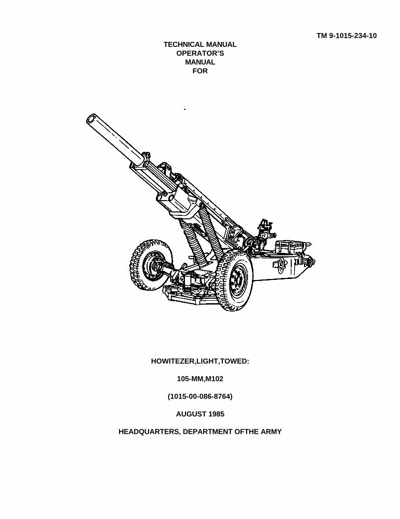
TM 9-1015-234-10TECHNICAL MANUAL
OPERATOR’SMANUAL
FOR
HOWITEZER,LIGHT,TOWED:
105-MM,M102
(1015-00-086-8764)
AUGUST 1985
HEADQUARTERS, DEPARTMENT OFTHE ARMY

TM 9-1015-234-10
CHANGE HEADQUARTERSDEPARTMENT OF THE ARMY
No. 2 Washington, DC 17 December 1993OPERATOR'S MAINTENANCE MANUAL
HOWITZER, LIGHT, TOWED:105-MM, M102
(NSN 1015-00-086-8164)
TM 9-101 .-234-10, 19 August 1985, is changed as follows:1. Remove old pages and insert new pages as indicated below.2. New or changed material is indicated by a vertical bar in the margin of the page.3. New or changed illustrations are indicated by a pointing hand highlighting the change.
Remove Pages Insert Pages
1-7 and 1-8 1-7 and 1-81-17 through 1-20 1-17 through 1-201-21 through 1-27(1-28 blank) None2-9 through 2-16 2-9 through 2-162-23 and 2-24 2-23 and 2-242-26.5 through 2-26.8 2-26.5 through 2-26.82-26.17 through 2-26.20 2-26.17 through 2-26.202-27 and 2-28 2-27 and 2-282-37 through 2-42 2-37 through 2-422-47 through 2-50 2-47 through 2-502-59 and 2-60 2-59 and 2-602-83 through 2-86 2-83 through 2-863-33 and 3-34 3-33 and 3-343-39 through 3-50 3-39 through 3-503-55 through 3-60 3-55 through 3-604-1 and 4-2 4-1 and 4-24-7 and 4-8 4-7 and 4-84-8.1(4-8.2 blank) 4-8.1 and 4-8.24-9 through 4-14 4-9 through 4-144-17 through 4-22 4-17 through 4-224-27 through 4-30 4-27 through 4-30

TM 9-1015-234-10
Remove Pages Insert Pages
4-33 and 4-34 4-33 and 4-34A-1 and A-2 A-1 and A-2B-7 and B-8 B-7 and B-8B-11 through B-16 B-11 through B-16C-1 through C-4 C-1 through C-4D-1 through D-5(D-6 blank) D-1 through D-5(D-6)blank)E-1 through E-4 E-1 through E-4Index 1 through Index 14 Index 1 through Index 14
File this sheet in the back of the manual for reference purposes.

TM 9-1015-234-10C1
CHANGE HEADQUARTERSDEPARTMENT OF THE ARMY
No. 1 Washington, DC 7 September 1990
OPERATOR'S MAINNANCE MANUAL
HOWITZER, LIGHT, TOWED:105-MM, M102
(NSN 1015-00-086-8164)
TM 9-1015-234-10, 19 August 1985, is changed as follows:
1. Remove old pages and insert new pages as indicated below.
2. New or changed material is indicated by a vertical bar in the margin of the page.
3. New or changed illustrations are indicated by a pointing hand highlighting the change.
Remove Pages Insert Pages
1-1 through 1-12 1-1 through 1-121-19 through 1-27/ 1-19 through 1-27/
(1-28 blank) (1-28 blank)2- through 2-26 2-7 through 2-26.202-27 and 2-28 2-27 and 2-282-31 and 2-32 2-31 and 2-322-35 and 2-36 2-35 and 2-362-41 through 2-54 2-41 through 2-542-57 through 2-60 2-57 through 2-602-63 through 2-66 2-63 through 2-66.1/(2-66.2 blank)2-67 through 2-74 2-67 through 2-742-77 through 2-86 2-77 through 2-862-89 through 2-92 2-89 through 2-923-1 through 3-4 3-1 through 3-43-33 through 3-44 3-33 through 3-443-49 and 3-50 3-49 through 3-50.1/(3-50.2 blank)3-53 and 3-54 3-53 through 3-54.1/(3-54.2 blank)3-59 through 3-61/ 3-59 through 3-61/
(3-62 blank) (3-62 blank)4-1 through 4-8 4-1 through 4-8.1/(4-8.2 blank)4-9 and 4-10 4-9 through 4-10.3/(4-10.4 blank)4-11 through 4-22 4-11 through 4-22.1/
(4-22.2 blank)
TM 9-1015-234-10
Remove Pages Insert Pages
4-23 and 4-24 4-23 through 4-24.5/(4-24.6 blank)
4-25 through 4-28 4-25 through 4-28/4-31 and 4-32 4-31 through 4-32.1(4-32.2 blank)4-35/(4-36 blank) 4-35/(4-36 blank)A-1 through A-3/ A-1 through A-3/
(A-4 blank) (A-4 blank)B-7 through B-16 B-7 through B-16C-3 and C-4 C-3 and C-4D-3 and D-4 D-3 and D-4
File this sheet in the back of the manual for reference purposes.
By Order of the Secretary of the Army:
CARL E. VUONOGeneral, United States Army
Chief of StaffOfficial:
THOMAS F. SIKORABrigadier General, ,United States Army
The Adjutant General
DISTRIBUTION:
To be distributed in accordance with DA Form 12-40E, (block 0017), Operator Maintenance requirements for TM 9-1015-234-10.
TM 9-1015-234-10WARNING
11 personnel that operate and/or maintain the M102 howitzer -and its fire control equipment must be aware of thefollowing special precautions.
RADIATION HAZARD
Rules and Regulations
Copies of the following rules and regulations are maintained at HQ, AMCCOM, Rock Island, IL 61299-6000. Copiesmay be requested, or information pertinent to these rules and regulations obtained, by contacting the AMCCOMRadiological Protection Officer (RPO), AUTOVON 793-3482, Commercial (309) 794-3483.
10CFR Part 19 - Notices, Instructions and Reports to Workers; Inspections.
10CFR Part 20 - Standards for Protection Against Radiation.
NRC license, license conditions, and license application.
Safety Precautions
The radioactive material used in this instrument is tritium gas (H ) sealed in pyrex tubes. It poses no significant hazard tomaintenance personnel when intact. These sources illuminate the instrumentation for night operations. Tampering withor removal of the sources in the field is prohibited by Federal law. In the event there is no illumination, notify the localRadiological Protection Officer. Do not attempt to repair or replace the instrument in the field! If skin contact is madewith any area contaminated with tritium, immediately wash with nonabrasive soap and water.
Identification
Radioactive self-luminous sources are identified by means of radioactive warning labels (as above). These labels shouldnot be defaced or removed, and should be replaced immediately when necessary. Refer to the local RPO or theAMCCOM RPO for instructions on handling, storage, or disposal.
a
WARNING TRITIUM (H3)

TM 9-1015-234-10
WARNING
Storage and Shipping
When radioactively illuminated instruments are defective, notify organizational maintenance. These items must beplaced in a plastic bag and packaged in the shipping container from which the replacement was taken before evacuationto a higher echelon is made. Spare equipment must be stored in the shipping container, as received, until installed onthe weapon. Storage of these items is recommended to be in an outdoor shed-type storage or unoccupied building.
HOWITZERGeneral
The procedures in this technical manual involve the use of a weapon system and live ammunition. All standard safetyprecautions governing the handling of live ammunition and operation of artillery weapons must be observed.
AMMUNITION
Do not chamber ammunition except immediately prior to firing. When possible, fire or unload ammunition within 5minutes after chambering. Ammunition left too long in a hot or warm weapon can result in cookoffs or inbore explosionswhich are hazardous to personnel. Use of ammunition other than that prescribed in this manual is prohibited.'
FIRST AID
For further information on first aid, see FM 21-11 (TEST).
b
*TM 9-1015-234-10Technical Manual HEADQUARTERS
DEPARTMENT OF THE ARMYNo. 9-1015-234-10 Washington, DC, 19 August 1985
Operator's Maintenance ManualHOWITZER, LIGHT, TOWED:
105-MM, M102(NSN 1015-00-086-8164)
REPORTING ERRORS AND RECOMMENDING IMPROVEMENTS
You can help improve this manual. If you find any mistakes, or if you know of a way to improvethe procedures, please let us know. Mail your letter, DA Form 2028 (Recommended Changes toPublications and Blank Forms), or DA Form 2028-2 located in the back of this manual direct to:Commander, US Army Armament, Munitions and Chemical Command, ATT: AMSNC- MAS,Rock Island, IL 61299-6000. A reply will be furnished to you.
Page
CHAPTER 1. INTRODUCTIONSection I. General Information .....................................................................................................1-1Section II. Equipment Description.................................................................................................1-6Section III. Section Drill .................................................................................................................1-21
CHAPTER 2. OPERATING INSTRUCTIONSSection I. Description
Controls and Indicators............................................................................................2-1Section II. Preventive Maintenance Checks
and Services (PMCS)..............................................................................................2-10Section III. Operation Under Usual Conditions. 2-27Section IV Operation Under Unusual Conditions. 2-87
CHAPTER 3. MAINTENANCE INSTRUCTIONSSection I. Lubrication Instructions ...............................................................................................3-1Section II. Troubleshooting Procedures ........................................................................................3-12Section III. Maintenance Procedures .............................................................................................3-29
*This manual supersedes TM 9-1015-234-10, 31 August 1979, including all changes in their entirety.
i
TM 9-1015-234-10
Page
CHAPTER 3. MAINTENANCE INSTRUCTIONS (cont)
Section IV. Maintenance of Auxiliary Equipment ............................................................................3-41Section V. Fire Control Alinement Tests
and Measurements ......................................................................................................3-41
CHAPTER 4. AMMUNITION FOR M102 HOWITZERWITH M137A1 SERIES CANNON
Section I. Introduction .................................................................................................................4-1Section II. Preparation for Firing ..................................................................................................4-14Section III. Maintenance of Ammunition .......................................................................................4-31
APPENDIX A. REFERENCES ...........................................................................................................A-1
APPENDIX B. COMPONENTS OF END ITEM AND BASICISSUE ITEMS LISTS
Section I. Introduction..................................................................................................................B-1Section II. Components of End Item .............................................................................................B-3Section III. Basic Issue Items. B-7
APPENDIX C. ADDITIONAL AUTHORIZATION LIST
Section I. Introduction .................................................................................................................C-1Section II. Additional Authorization List ........................................................................................C-2
APPENDIX D. EXPENDABLE/DURABLE SUPPLIES ANDMATERIALS LIST
Section I. Introduction..................................................................................................................D-1
Section II. Expendable/Durable Supplies andMaterials List ...............................................................................................................D-2
APPENDIX E. STOWAGE AND SIGN GUIDE (FOR COMPONENTSOF END ITEM, BASIC ISSUE ITEMS, ANDAPPLICABLE ADDITIONAL AUTHORIZATIONLIST ITEMS)................................................................................................................E-1
ALPHABETICAL INDEX..............................................................................................................................Index 1
ii
TM 9-1015-234-10
CHAPTER 1INTRODUCTION
Section I. GENERAL INFORMATION
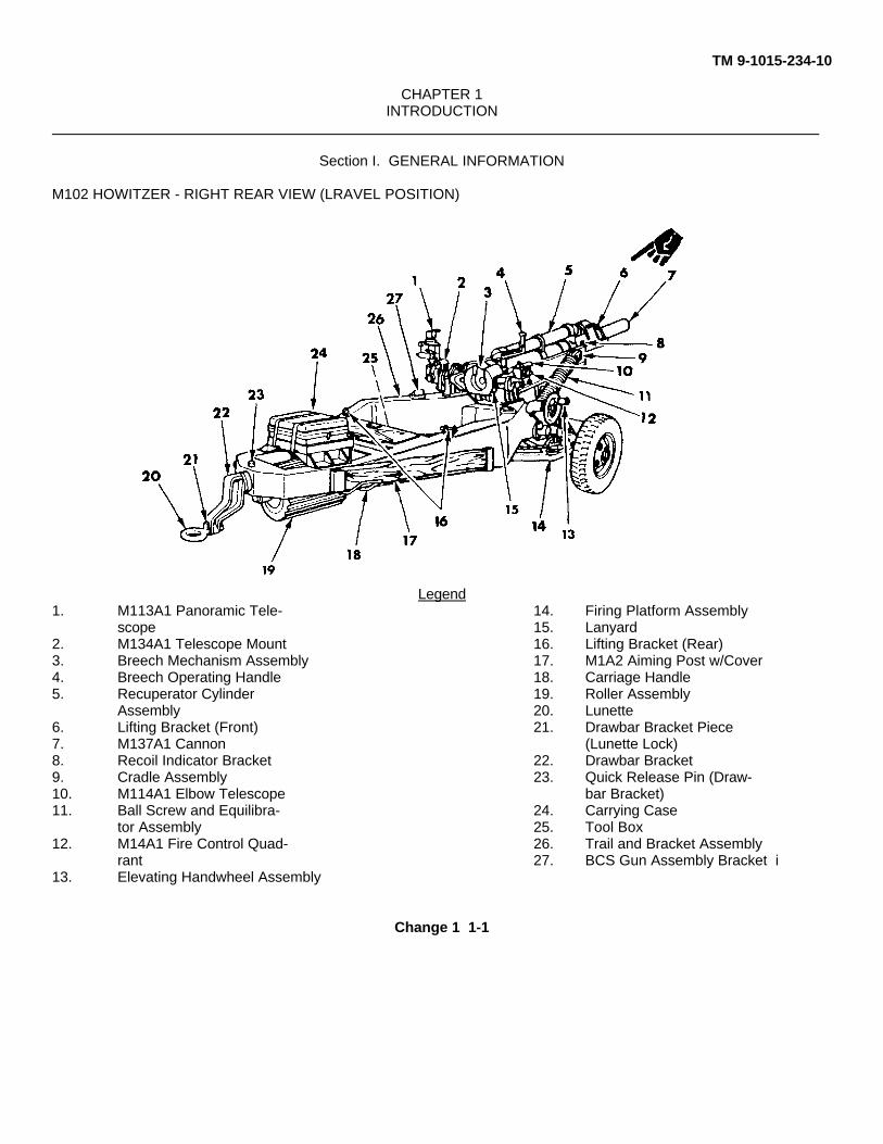
M102 HOWITZER - RIGHT REAR VIEW (LRAVEL POSITION)
Legend1. M113A1 Panoramic Tele- 14. Firing Platform Assembly
scope 15. Lanyard2. M134A1 Telescope Mount 16. Lifting Bracket (Rear)3. Breech Mechanism Assembly 17. M1A2 Aiming Post w/Cover4. Breech Operating Handle 18. Carriage Handle5. Recuperator Cylinder 19. Roller Assembly
Assembly 20. Lunette6. Lifting Bracket (Front) 21. Drawbar Bracket Piece7. M137A1 Cannon (Lunette Lock)8. Recoil Indicator Bracket 22. Drawbar Bracket9. Cradle Assembly 23. Quick Release Pin (Draw-10. M114A1 Elbow Telescope bar Bracket)11. Ball Screw and Equilibra- 24. Carrying Case
tor Assembly 25. Tool Box12. M14A1 Fire Control Quad- 26. Trail and Bracket Assembly
rant 27. BCS Gun Assembly Bracket i13. Elevating Handwheel Assembly
Change 1 1-1
TM 9-1015-234-10
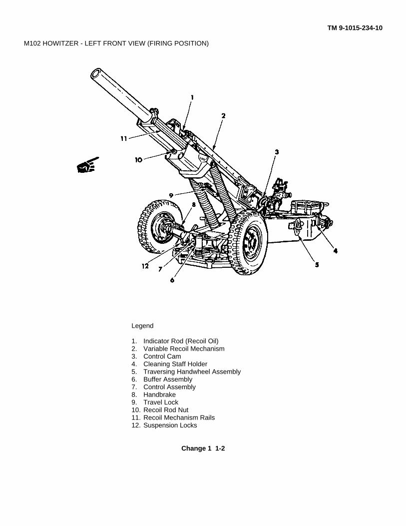
M102 HOWITZER - LEFT FRONT VIEW (FIRING POSITION)
Legend
1. Indicator Rod (Recoil Oil)2. Variable Recoil Mechanism3. Control Cam4. Cleaning Staff Holder5. Traversing Handwheel Assembly6. Buffer Assembly7. Control Assembly8. Handbrake9. Travel Lock10. Recoil Rod Nut11. Recoil Mechanism Rails12. Suspension Locks
Change 1 1-2
TM 9-1015-234-10
1-1. SCOPEa. Type of Manual. Operator's.
b. Model Number and Equipment Name. M102 105-mm towed light howitzer.
c. Purpose of Equipment. Provides artillery fire in support of ground-gaining troops.
d. Special Inclusions in Manual. Crew drill procedures.
1-2. MAINTENANCE FORMS AND RECORDS
Department of the Army forms and procedures used for equipment maintenance will be those prescribed by DA PAM738-750, The Army Maintenance Management System (TAMMS), as contained in Maintenance Management Update.
1-3. HAND RECEIPT (-HR) MANUALS
This manual has a companion document with a TM number followed by "-HR" (which stands for Hand Receipt). The TM9-1015-234-10-HR consists of preprinted hand receipts (DA Form 2062) that list end item related equipment (i.e., COEI,BII, and AAL) you must account for. As an aid to property accountability, additional -HR manuals may be requisitionedfrom the following source in accordance with procedures in AR 25-30:
Commander, US Army Publications and Distribution Center 2800 Eastern Boulevard Baltimore, MD 21220-2896
1-4. REPORTING EQUIPMENT IMPROVEMENT RECOMENDATIONS (EIR's)
If your M102 howitzer needs improvement, let us know. Send us an EIR. You, the user, are the only one who can tell uswhat you don't like about your equipment. Let us know why you don't like the design or performance. Put it on an SF368 (Quality Deficiency Report). Mail it to us at US Army Armament, Munitions,, and Chemical Command, ATTN:A1SMC-QAD, Pock Island, IL 61299-6000. We'll send you a reply.
Change 1 1-3

TM 9-1015-234-10
1-5. NOMENCLATURE CROSS-REFERENCE LIST
Throughout this manual, most items are referred to by their official nomenclature. The items referred to by their commonnames are listed below, followed by their official nomenclature.
Common Name Official Nomenclature
Azimuth knob assembly .......................................................................................................................... Knob assemblyBell rammer ........................................................................................................................ Rammer, artillery, unloadingBoresighting string .................................................................................................................................... Twine, fibrousBreech operating handle .......................................................................................................................Handle assemblyCross level seat ..................................................................................................................................... Screw, machineElevation seat ........................................................................................................................................ Screw, machineExhaust port screw................................................................................................................................. Screw, machineHandbrake .............................................................................................................Spindle, brake and support assemblyIndicator rod...........................................................................................................................................................PistonLevel vial ............................................................................................................................................. Level, fire controlLifting bracket (front) .................................................................................................. Yoke, recoil mechanism assemblyOut of battery lock...........................................................................................................Pin, quick release; hook, chain,
S; cable assembly; and pin, cotterPantel ...........................................................................................................................................Telescope, panoramicPlunger lever......................................................................................................................... Post, electrical-mechanicalPlunger release lever ........................................................................................................................................ SetscrewQuadrant pad ......................................................................................................................................... Screw, machineRange knob assembly ............................................................................................................................. Knob assemblyRecoil rod nut....................................................................................................................................... Nut, plain, slottedSuspension lock ..................................................................................................................... Bracket; and pin assemblyTravel lock ..................................................................................................................... Traveling lock, cradle assemblyTrunnion................................................................................................................................... Bushing, sleeve; and cap
1-6. LIST OF ABBREVIATIONS
Abbreviation Definition
A .......................................................................................................................................................................AfterAAL ...................................................................................................................................Additional Authorization ListAG ....................................................................................................................................................Assistant GunnerAR ................................................................................................................................................... Army RegulationATC ........................................................................................................................................ Ammunition Team ChiefB ....................................................................................................................................................................BeforeBCS ...................................................................................................................................... Battery Computer SystemBII ...................................................................................................................................................Basic Issue ItemsC ....................................................................................................................................................... Operator/CrewCOEI ....................................................................................................................................... Components of End Item
Change 1 1-4

TM 9-1015-234-10
Abbreviation Definition
CS ......................................................................................................................................................... Chief of SectionCTA ..................................................................................................................................Common Table of AllowancesDA .............................................................................................................................................................Driver; DuringDA .............................................................................................................................................Department of the ArmyDAP ..........................................................................................................................Department of the Army ProcedureEFC .............................................................................................................................................Equivalent Full ChargeEIR .............................................................................................................. Equipment Improvement RecommendationFM .............................................................................................................................................................. Field ManualG..........................................................................................................................................................................GunnerHR ............................................................................................................................................................. Hand ReceiptGA ......................................................................................................................................................................monthlyGDU...............................................................................................................................................Gunner's Display UnitMT ........................................................................................................................................................Mechanical TimeHR ............................................................................................................................................................. Hand ReceiptM ........................................................................................................................................................................ MonthlyMT ........................................................................................................................................................Mechanical TimeMTOE .....................................................................................................Modified Table of Organization and EquipmentNBC............................................................................................................................Nuclear, Biological, and ChemicalO..........................................................................................................................................Organizational MaintenancePMCS ......................................................................................................Preventive Maintenance Checks and ServicesRPO.................................................................................................................................Radiological Protection OfficerSF............................................................................................................................................................Standard FormSQ/D....................................................................................................................................................Superquick/DelayTOE ...................................................................................................................... Table of Organization and EquipmentTE........................................................................................................................................................Technical ManualTM .......................................................................................................................................................Technical ManualU/M.........................................................................................................................................................Unit of MeasureW.........................................................................................................................................................................Weekly
Change 1 1-5
TM 9-1015-234-10
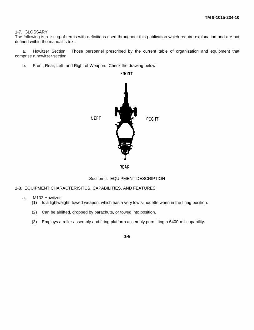
1-7. GLOSSARYThe following is a listing of terms with definitions used throughout this publication which require explanation and are notdefined within the manual 's text.
a. Howitzer Section. Those personnel prescribed by the current table of organization and equipment thatcomprise a howitzer section.
b. Front, Rear, Left, and Right of Weapon. Check the drawing below:
Section II. EQUIPMENT DESCRIPTION
1-8. EQUIPMENT CHARACTERISITCS, CAPABILITIES, AND FEATURES
a. M102 Howitzer.(1) Is a lightweight, towed weapon, which has a very low silhouette when in the firing position.
(2) Can be airlifted, dropped by parachute, or towed into position.
(3) Employs a roller assembly and firing platform assembly permitting a 6400-mil capability.
1-6

TM 9-1015-234-10
(4) Has a variable recoil system which eliminates the need for a recoil pit.
b. M102 Howitzer Fire Control and Sighting Equipment. Is divided into three groups.
(1) Indirect fire instruments are used when the target is not visible from the weapon and include:
M113A1 panoramic telescopeM134A1 telescope mountM14A1 fire control quadrant
(2) Direct fire instruments are used when the target is visible from the weapon and include:
M113A1 panoramic telescopeM134A1 telescope mountM114A1 elbow telescopeM14A1 fire control quadrant
(3) Miscellaneous instruments include:
M140 alinement deviceM1A1 gunners quadrantM1A1 infinity aiming collimatorM1A2 aiming postsM14 aiming post lightsM16 fuze wrenchM18 fuze wrenchM27 fuze setterM34 fuze setterM35 fuze setter
(4) Associated equipment includes: M90 radar chronograph Battery computer system (BCS)
Change 2 1-7
TM 9-1015-234-10
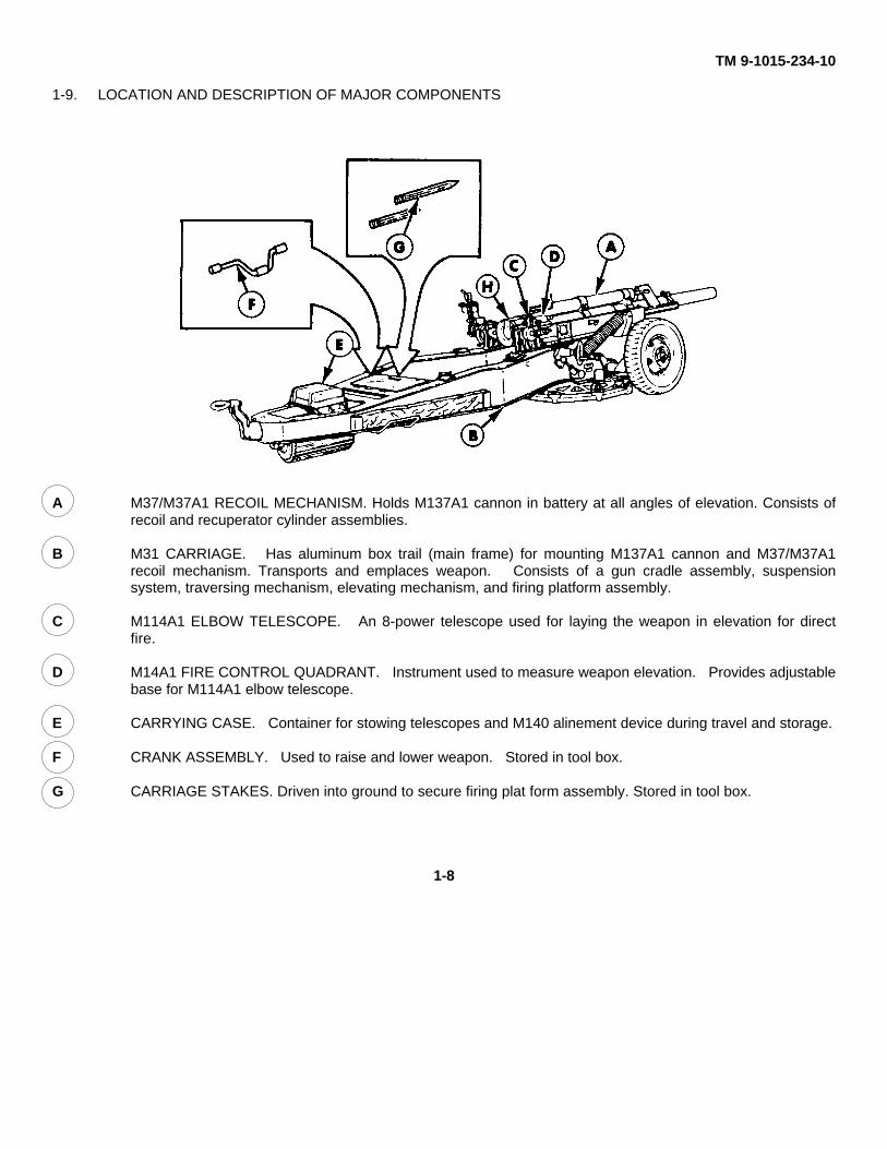
1-9. LOCATION AND DESCRIPTION OF MAJOR COMPONENTS
A M37/M37A1 RECOIL MECHANISM. Holds M137A1 cannon in battery at all angles of elevation. Consists ofrecoil and recuperator cylinder assemblies.
B M31 CARRIAGE. Has aluminum box trail (main frame) for mounting M137A1 cannon and M37/M37A1recoil mechanism. Transports and emplaces weapon. Consists of a gun cradle assembly, suspensionsystem, traversing mechanism, elevating mechanism, and firing platform assembly.
C M114A1 ELBOW TELESCOPE. An 8-power telescope used for laying the weapon in elevation for directfire.
D M14A1 FIRE CONTROL QUADRANT. Instrument used to measure weapon elevation. Provides adjustablebase for M114A1 elbow telescope.
E CARRYING CASE. Container for stowing telescopes and M140 alinement device during travel and storage.
F CRANK ASSEMBLY. Used to raise and lower weapon. Stored in tool box.
G CARRIAGE STAKES. Driven into ground to secure firing plat form assembly. Stored in tool box.
1-8
TM 9-1015-234-10
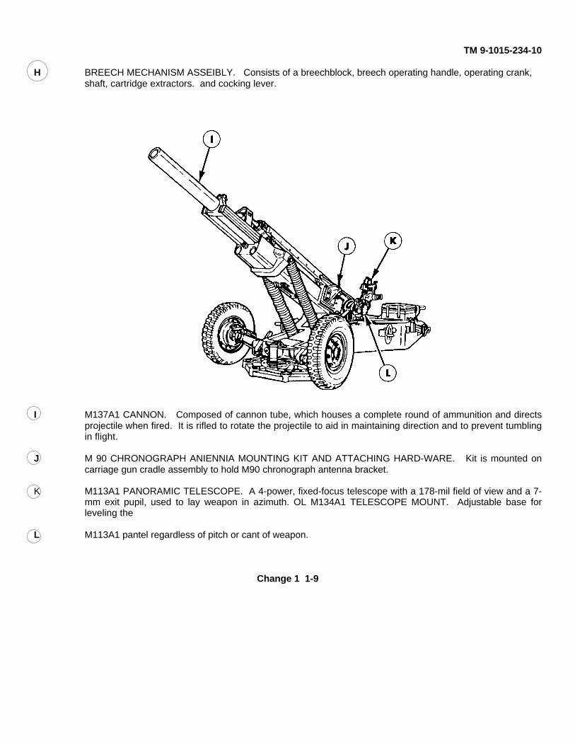
H BREECH MECHANISM ASSEIBLY. Consists of a breechblock, breech operating handle, operating crank, shaft, cartridge extractors. and cocking lever.
I M137A1 CANNON. Composed of cannon tube, which houses a complete round of ammunition and directsprojectile when fired. It is rifled to rotate the projectile to aid in maintaining direction and to prevent tumblingin flight.
J M 90 CHRONOGRAPH ANIENNIA MOUNTING KIT AND ATTACHING HARD-WARE. Kit is mounted oncarriage gun cradle assembly to hold M90 chronograph antenna bracket.
K M113A1 PANORAMIC TELESCOPE. A 4-power, fixed-focus telescope with a 178-mil field of view and a 7-mm exit pupil, used to lay weapon in azimuth. OL M134A1 TELESCOPE MOUNT. Adjustable base forleveling the
L M113A1 pantel regardless of pitch or cant of weapon.
Change 1 1-9
TM 9-1015-234-10
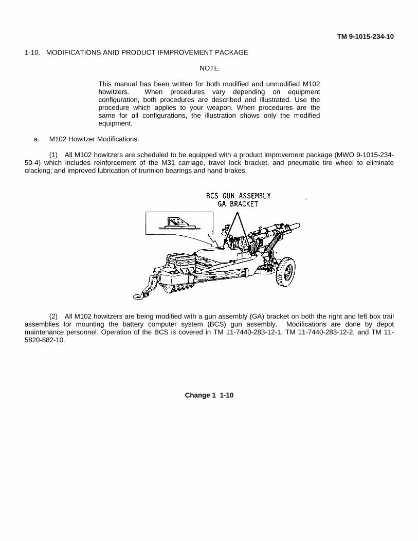
1-10. MODIFICATIONS ANID PRODUCT IFMPROVEMENT PACKAGE
NOTE
This manual has been written for both modified and unmodified M102howitzers. When procedures vary depending on equipmentconfiguration, both procedures are described and illustrated. Use theprocedure which applies to your weapon. When procedures are thesame for all configurations, the illustration shows only the modifiedequipment.
a. M102 Howitzer Modifications.
(1) All M102 howitzers are scheduled to be equipped with a product improvement package (MWO 9-1015-234-50-4) which includes reinforcement of the M31 carriage, travel lock bracket, and pneumatic tire wheel to eliminatecracking; and improved lubrication of trunnion bearings and hand brakes.
(2) All M102 howitzers are being modified with a gun assembly (GA) bracket on both the right and left box trailassemblies for mounting the battery computer system (BCS) gun assembly. Modifications are done by depotmaintenance personnel. Operation of the BCS is covered in TM 11-7440-283-12-1, TM 11-7440-283-12-2, and TM 11-5820-882-10.
Change 1 1-10
TM 9-1015-234-10
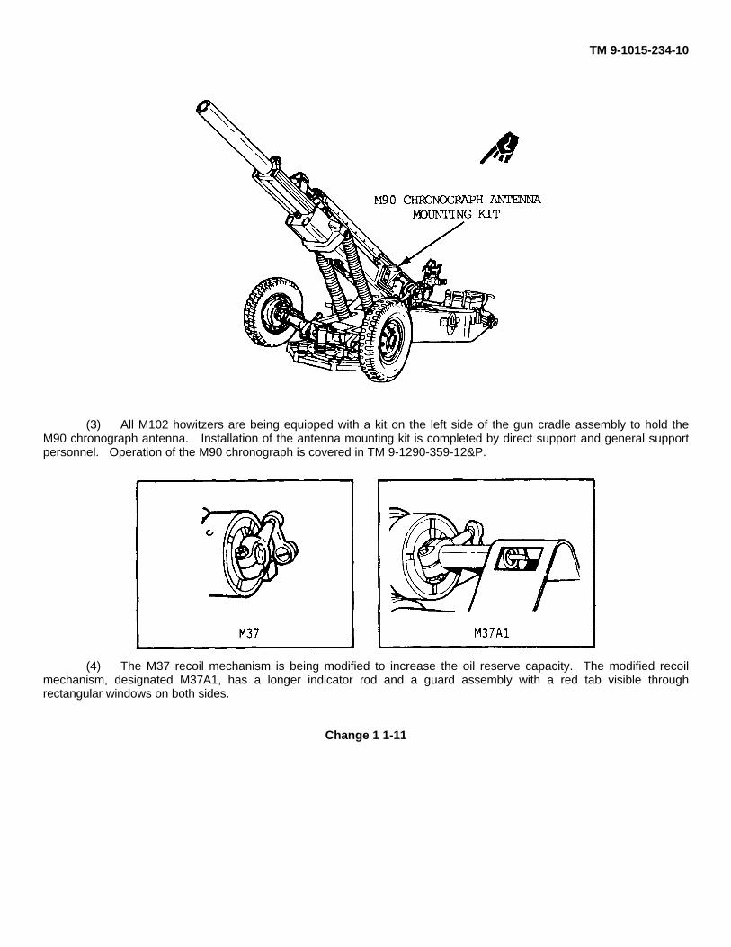
(3) All M102 howitzers are being equipped with a kit on the left side of the gun cradle assembly to hold theM90 chronograph antenna. Installation of the antenna mounting kit is completed by direct support and general supportpersonnel. Operation of the M90 chronograph is covered in TM 9-1290-359-12&P.
(4) The M37 recoil mechanism is being modified to increase the oil reserve capacity. The modified recoilmechanism, designated M37A1, has a longer indicator rod and a guard assembly with a red tab visible throughrectangular windows on both sides.
Change 1 1-11

TM 9-1015-234-10
1-10. MODIFICATIONS AND PRODUCT IMPROVEMENT PACKAGE (cont)
b. Fire Control Equipment Modifications. Modification is completed by depot maintenance personnel on theM113A1 panoramic telescope, providing new seals to protect the optics against moisture and installing a wear resistantelbow lock plate; and modifies the M14A1 fire control quadrant to provide an improved rotating counter. 1-11.EQUIPMENT DATA
HOWITZER DATA
Weight:Complete M102 howitzer .......................................................................................3180 lb (1442.448 kg)With on-carriage equipment ..................................................................................3335 lb (1512.756 kg)With complete BII ..................................................................................................3670 lb (1664.712 kg)Cross country (airlift) ..............................................................................................3670 lb (1664.712 kg)Roll bar ......................................................................................................................160 lb (72.576 kg)
Tire size ......................................................................................................................................7:00 x 16, 4 plyTire pressure..................................................................................................................................20 psi normal
40 psi super highway
Maximum range ........................................................................................................................... 11,500 metersDesignated prime movers .......................................................................................1-1/4 ton and 2-1/2 ton truckDimensions (travel conditions):
Length.................................................................................................................. 21 ft 10-1/2 in. (6.7 m)Width .............................................................................................................................6 ft 4 in. (1.9 m)Height ......................................................................................................................5 ft 2-3/4 in. (1.6 m)
Lunette load ............................................................................................................................225 lb (101.25 kg)Elevation range........................................................................................................................-89 to +1333 milsRate of fire ................................................................................................................. Maximum (1st 3 minutes),
10 rpm; sustained, 3 rpmRecoil length at O-mil elevation .................................................................................................... 50 in. approx
(1.3 m)Recoil length at 1250-mil elevation ............................................................................................... 30 in. approx
(76 cm)Maximum towing speed:
Super highway ............................................................................................................................. 45 mphImproved roads ............................................................................................................................ 35 mphCross country ............................................................................................................................... 10 mph
FIRE CONTROL EQUIPMENT DATA
M113A1 Panoramic TelescopeField of view................................................................................................................................178 milsMovement:Azimuth counter ........................................................................................................................6400 milsAzimuth (deflection) ..................................................................................................................6400 milsCorrection (AZ) .............................................................................................................................50 milsElevation.....................................................................................................................................300 mils
Change 1 1-12
TM 9-1015-234-10
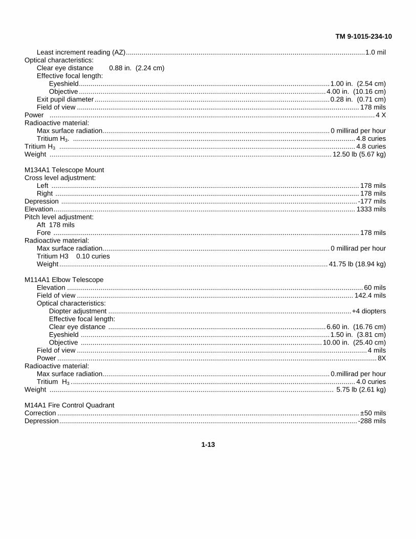
Least increment reading (AZ)..........................................................................................................................1.0 milOptical characteristics:
Clear eye distance 0.88 in. (2.24 cm)Effective focal length:
Eyeshield................................................................................................................................1.00 in. (2.54 cm)Objective .............................................................................................................................. 4.00 in. (10.16 cm)
Exit pupil diameter ........................................................................................................................0.28 in. (0.71 cm)Field of view ................................................................................................................................................ 178 mils
Power ...................................................................................................................................................................... 4 XRadioactive material:
Max surface radiation.................................................................................................................... 0 millirad per hourTritium H3. ................................................................................................................................................ 4.8 curies
Tritium H3 ....................................................................................................................................................... 4.8 curiesWeight ................................................................................................................................................ 12.50 lb (5.67 kg)
M134A1 Telescope MountCross level adjustment:
Left ............................................................................................................................................................. 178 milsRight ........................................................................................................................................................... 178 mils
Depression ....................................................................................................................................................... -177 milsElevation.......................................................................................................................................................... 1333 milsPitch level adjustment:
Aft 178 milsFore ............................................................................................................................................................ 178 mils
Radioactive material:Max surface radiation.................................................................................................................... 0 millirad per hourTritium H3 0.10 curiesWeight ......................................................................................................................................... 41.75 lb (18.94 kg)
M114A1 Elbow TelescopeElevation ....................................................................................................................................................... 60 milsField of view ............................................................................................................................................. 142.4 milsOptical characteristics:
Diopter adjustment ............................................................................................................................+4 dioptersEffective focal length:Clear eye distance ............................................................................................................... 6.60 in. (16.76 cm)Eyeshield ...............................................................................................................................1.50 in. (3.81 cm)Objective ........................................................................................................................... 10.00 in. (25.40 cm)
Field of view .................................................................................................................................................... 4 milsPower ................................................................................................................................................................... 8X
Radioactive material:Max surface radiation.................................................................................................................... 0.millirad per hourTritium H3 ................................................................................................................................................. 4.0 curies
Weight ................................................................................................................................................. 5.75 lb (2.61 kg)
M14A1 Fire Control QuadrantCorrection .......................................................................................................................................................... ±50 milsDepression........................................................................................................................................................ -288 mils
1-13
TM 9-1015-234-10
1-11. EQUIPMENT DATA (cont)FIRE CONTROL EQUIPMENT DATA (cont)
M14A1 Fire Control Quadrant (cont)Elevation.................................................................................................................................. +1383 milsLeast increment reading (counters) ....................................................................................................1 milRadioactive material:
Max surface radiation.............................................................................................. 0 millirad per hourTritium H3.......................................................................................................................... 2.10 curies
Weight ........................................................................................................................... 14.75 lb (6.69 kg)
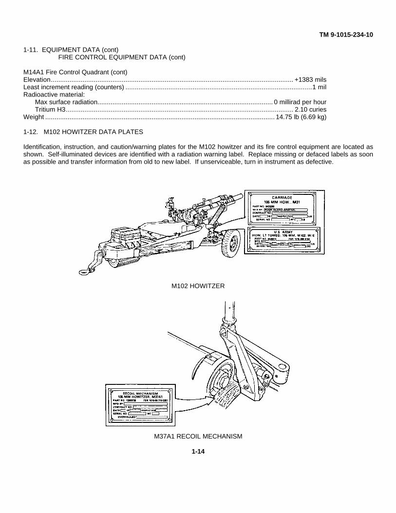
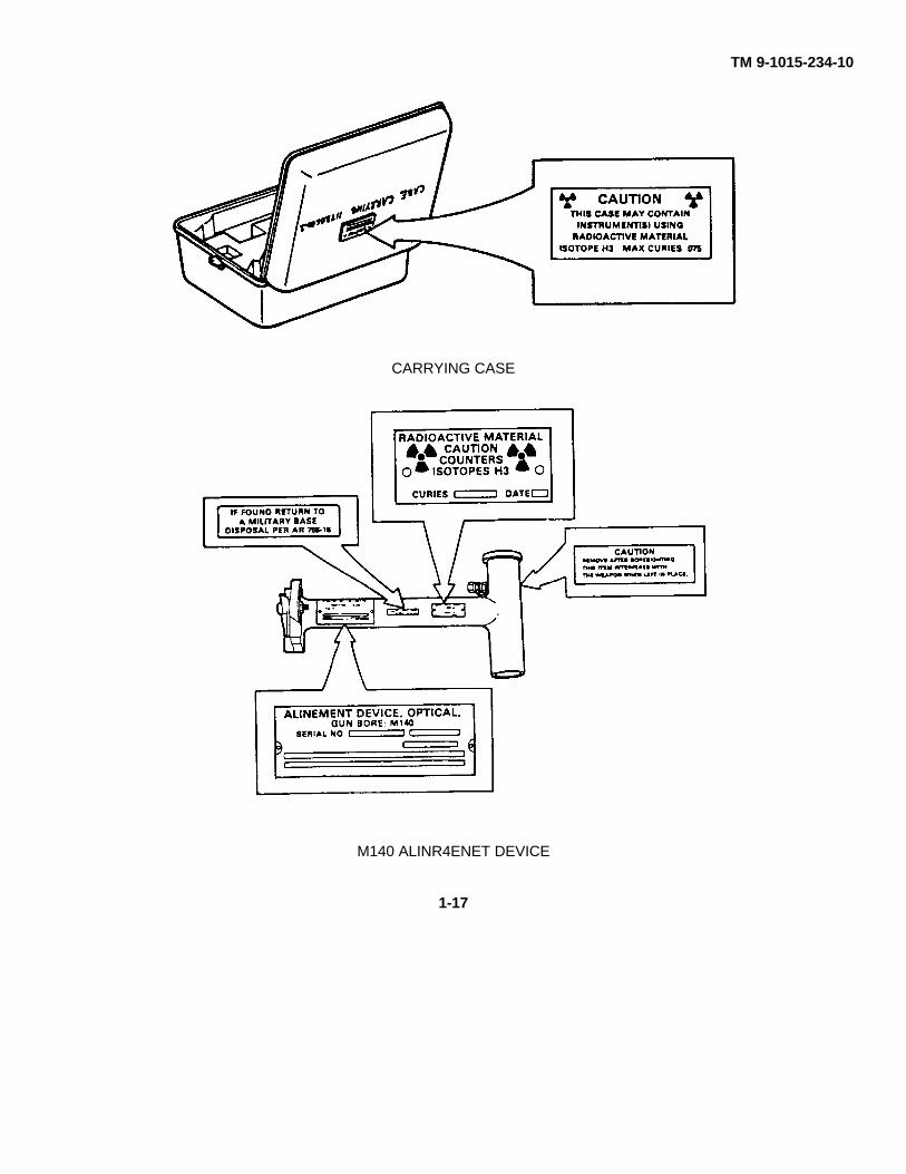
1-12. M102 HOWITZER DATA PLATES
Identification, instruction, and caution/warning plates for the M102 howitzer and its fire control equipment are located asshown. Self-illuminated devices are identified with a radiation warning label. Replace missing or defaced labels as soonas possible and transfer information from old to new label. If unserviceable, turn in instrument as defective.
M102 HOWITZER
M37A1 RECOIL MECHANISM
1-14
TM 9-1015-234-10
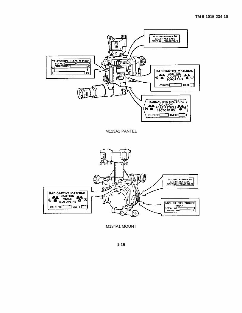
M113A1 PANTEL
M134A1 MOUNT
1-15
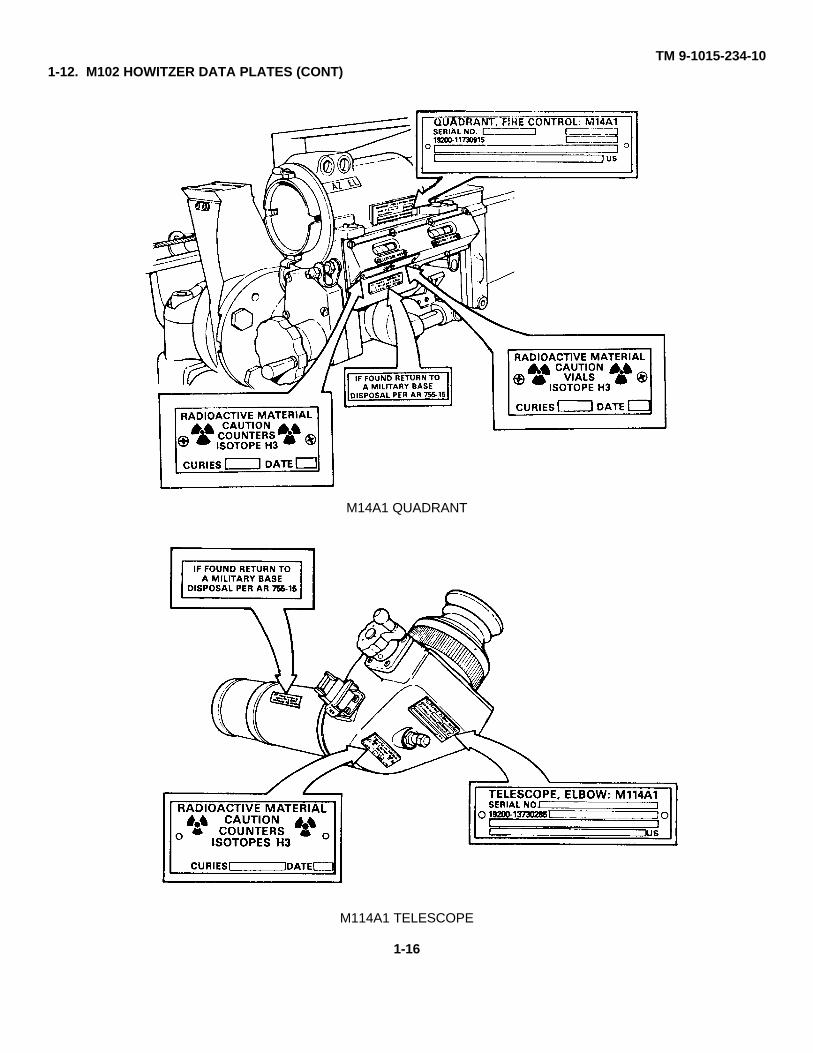
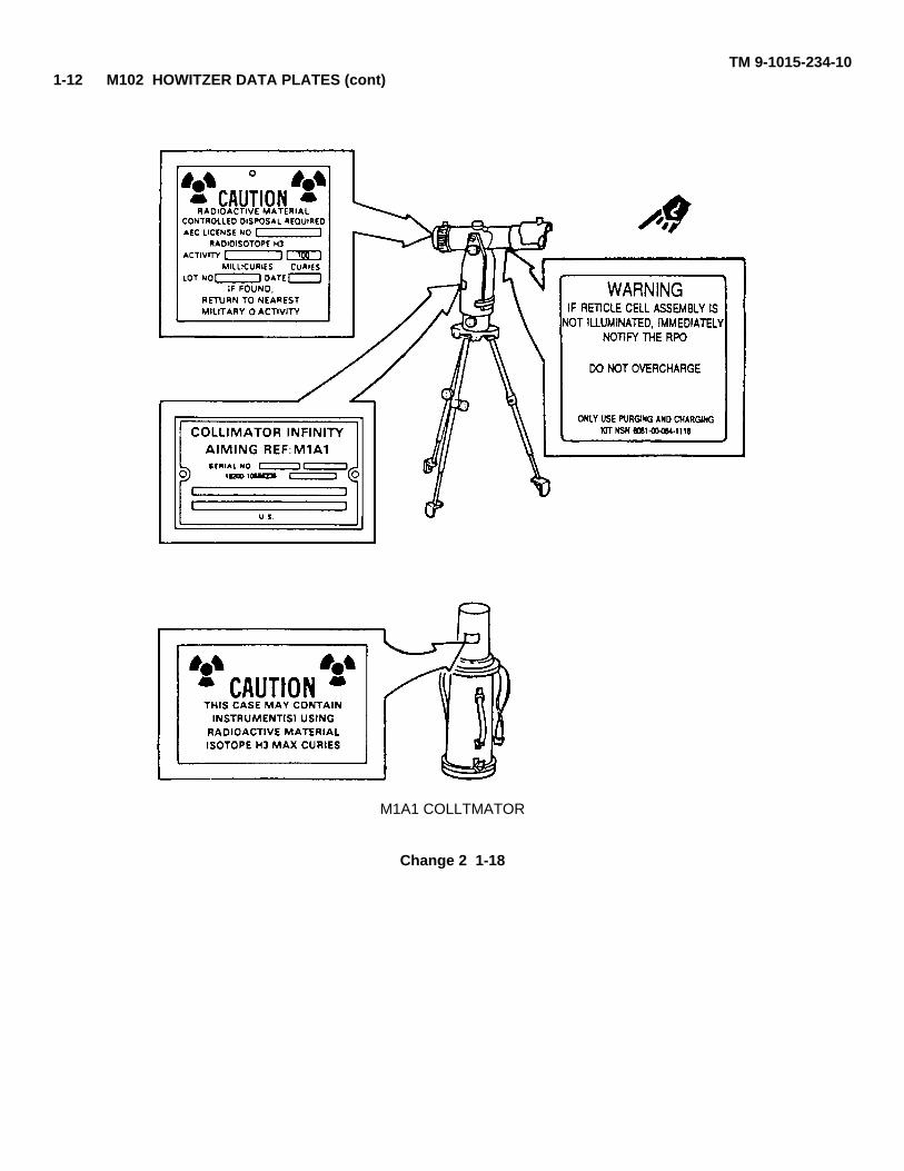
TM 9-1015-234-101-12. M102 HOWITZER DATA PLATES (CONT)
M14A1 QUADRANT
M114A1 TELESCOPE
1-16
TM 9-1015-234-10
CARRYING CASE
M140 ALINR4ENET DEVICE
1-17
TM 9-1015-234-101-12 M102 HOWITZER DATA PLATES (cont)
M1A1 COLLTMATOR
Change 2 1-18
TM 9-1015-234-10
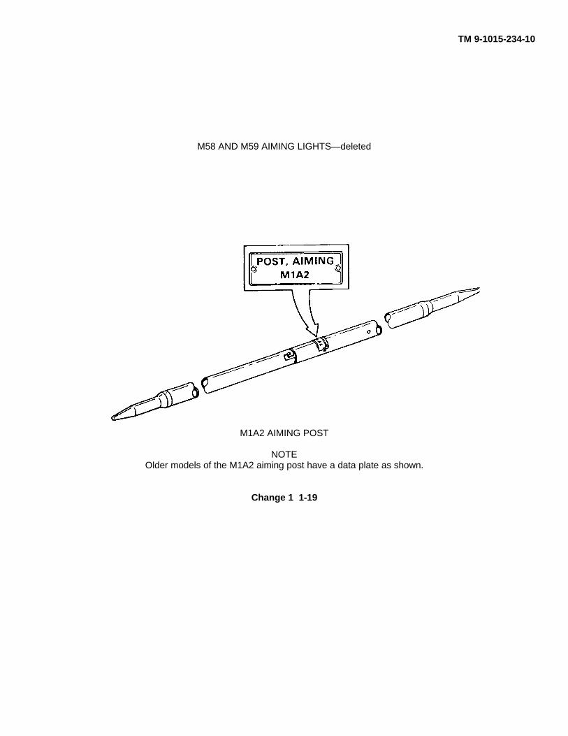
M58 AND M59 AIMING LIGHTS—deleted
M1A2 AIMING POST
NOTEOlder models of the M1A2 aiming post have a data plate as shown.
Change 1 1-19
TM 9-1015-234-10
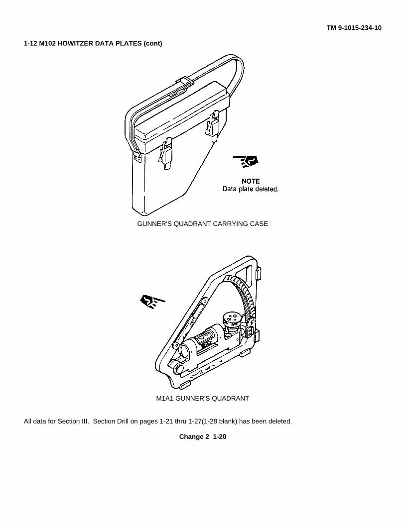
1-12 M102 HOWITZER DATA PLATES (cont)
GUNNER'S QUADRANT CARRYING CASE
M1A1 GUNNER'S QUADRANT
All data for Section III. Section Drill on pages 1-21 thru 1-27(1-28 blank) has been deleted.
Change 2 1-20
TM 9-1015-234-10
CHAPTER 2OPERATING INSTRUCTIONS
Section I. DESCRIPTION AND USE OF OPERATOR'S CONTROLSAND INDICATORS
2-1.GENERALBefore attempting to operate the M102 howitzer, make certain you are familiar with the location andoperation of all controls and indicators.
2-2.OPERATOR'S CONTROLS AND INDICATORS
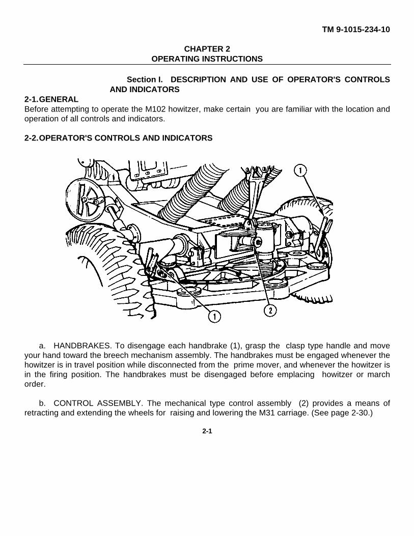
a. HANDBRAKES. To disengage each handbrake (1), grasp the clasp type handle and moveyour hand toward the breech mechanism assembly. The handbrakes must be engaged whenever thehowitzer is in travel position while disconnected from the prime mover, and whenever the howitzer isin the firing position. The handbrakes must be disengaged before emplacing howitzer or marchorder.
b. CONTROL ASSEMBLY. The mechanical type control assembly (2) provides a means ofretracting and extending the wheels for raising and lowering the M31 carriage. (See page 2-30.)
2-1
TM 9-1015-234-10
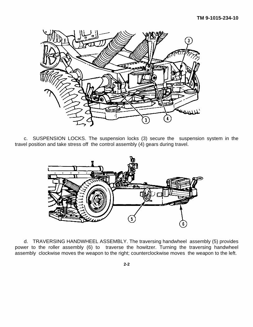
c. SUSPENSION LOCKS. The suspension locks (3) secure the suspension system in thetravel position and take stress off the control assembly (4) gears during travel.
d. TRAVERSING HANDWHEEL ASSEMBLY. The traversing handwheel assembly (5) providespower to the roller assembly (6) to traverse the howitzer. Turning the traversing handwheelassembly clockwise moves the weapon to the right; counterclockwise moves the weapon to the left.
2-2
TM 9-1015-234-10
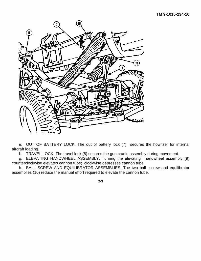
e. OUT OF BATTERY LOCK. The out of battery lock (7) secures the howitzer for internalaircraft loading.
f. TRAVEL LOCK. The travel lock (8) secures the gun cradle assembly during movement.g. ELEVATING HANDWHEEL ASSEMBLY. Turning the elevating handwheel assembly (9)
counterclockwise elevates cannon tube; clockwise depresses cannon tube.h. BALL SCREW AND EQUILIBRATOR ASSEMBLIES. The two ball screw and equilibrator
assemblies (10) reduce the manual effort required to elevate the cannon tube.
2-3
TM 9-1015-234-10
2-2. OPERATOR’S CONTROLS AND INDICATORS (cont)
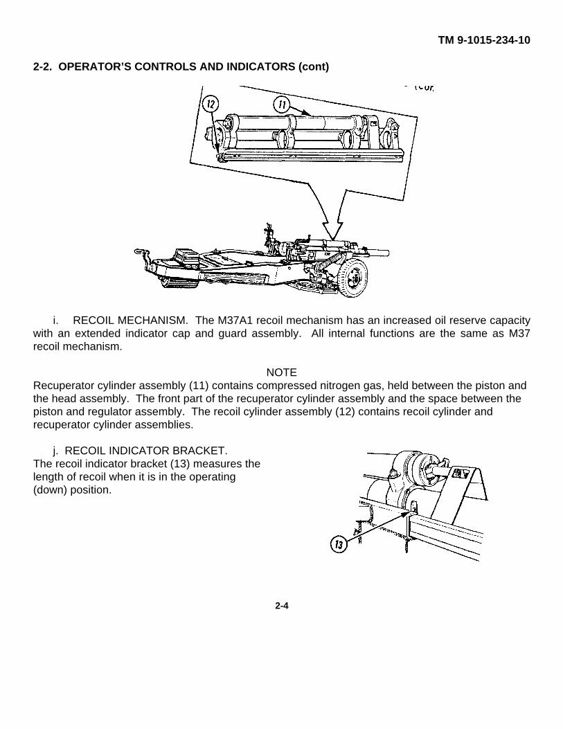
i. RECOIL MECHANISM. The M37A1 recoil mechanism has an increased oil reserve capacitywith an extended indicator cap and guard assembly. All internal functions are the same as M37recoil mechanism.
NOTERecuperator cylinder assembly (11) contains compressed nitrogen gas, held between the piston andthe head assembly. The front part of the recuperator cylinder assembly and the space between thepiston and regulator assembly. The recoil cylinder assembly (12) contains recoil cylinder andrecuperator cylinder assemblies.
j. RECOIL INDICATOR BRACKET.The recoil indicator bracket (13) measures thelength of recoil when it is in the operating(down) position.
2-4
TM 9-1015-234-10
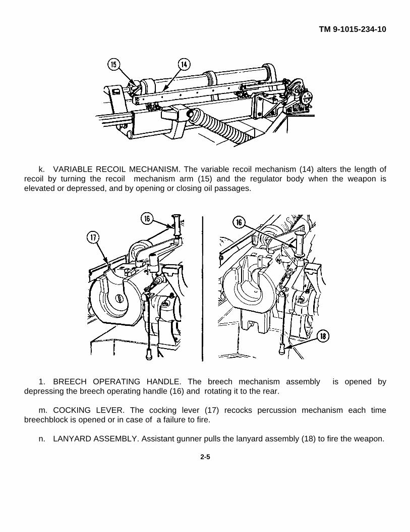
k. VARIABLE RECOIL MECHANISM. The variable recoil mechanism (14) alters the length ofrecoil by turning the recoil mechanism arm (15) and the regulator body when the weapon iselevated or depressed, and by opening or closing oil passages.
1. BREECH OPERATING HANDLE. The breech mechanism assembly is opened bydepressing the breech operating handle (16) and rotating it to the rear.
m. COCKING LEVER. The cocking lever (17) recocks percussion mechanism each timebreechblock is opened or in case of a failure to fire.
n. LANYARD ASSEMBLY. Assistant gunner pulls the lanyard assembly (18) to fire the weapon.
2-5
TM 9-1015-234-10
2-2.OPERATOR'S CONTROLS AND INDICATORS (cont)
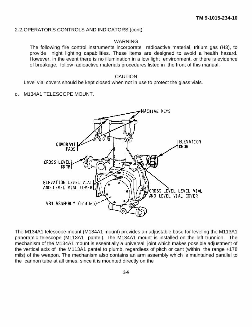
WARNINGThe following fire control instruments incorporate radioactive material, tritium gas (H3), toprovide night lighting capabilities. These items are designed to avoid a health hazard.However, in the event there is no illumination in a low light environment, or there is evidenceof breakage, follow radioactive materials procedures listed in the front of this manual.
CAUTIONLevel vial covers should be kept closed when not in use to protect the glass vials.
o. M134A1 TELESCOPE MOUNT.
The M134A1 telescope mount (M134A1 mount) provides an adjustable base for leveling the M113A1panoramic telescope (M113A1 pantel). The M134A1 mount is installed on the left trunnion. Themechanism of the M134A1 mount is essentially a universal joint which makes possible adjustment ofthe vertical axis of the M113A1 pantel to plumb, regardless of pitch or cant (within the range +178mils) of the weapon. The mechanism also contains an arm assembly which is maintained parallel tothe cannon tube at all times, since it is mounted directly on the
2-6
TM 9-1015-234-10
weapon trunnion. This arm assembly serves as a reference about which the M134A1 mount isadjusted to compensate the azimuth for the effects of trunnion cant. The M134A1 mount provides avertical support for the M113A1 pantel to provide a true measurement of weapon azimuth.
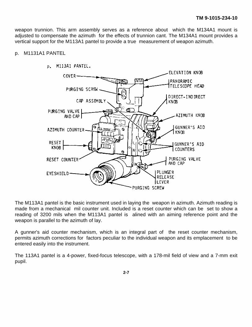
p. M1131A1 PANTEL
The M113A1 pantel is the basic instrument used in laying the weapon in azimuth. Azimuth reading ismade from a mechanical mil counter unit. Included is a reset counter which can be set to show areading of 3200 mils when the M113A1 pantel is alined with an aiming reference point and theweapon is parallel to the azimuth of lay.
A gunner's aid counter mechanism, which is an integral part of the reset counter mechanism,permits azimuth corrections for factors peculiar to the individual weapon and its emplacement to beentered easily into the instrument.
The 113A1 pantel is a 4-power, fixed-focus telescope, with a 178-mil field of view and a 7-mm exitpupil.
2-7
TM 9-1015-234-102-2. OPERATOR’S CONTROLS AND INDICATORS (cont)
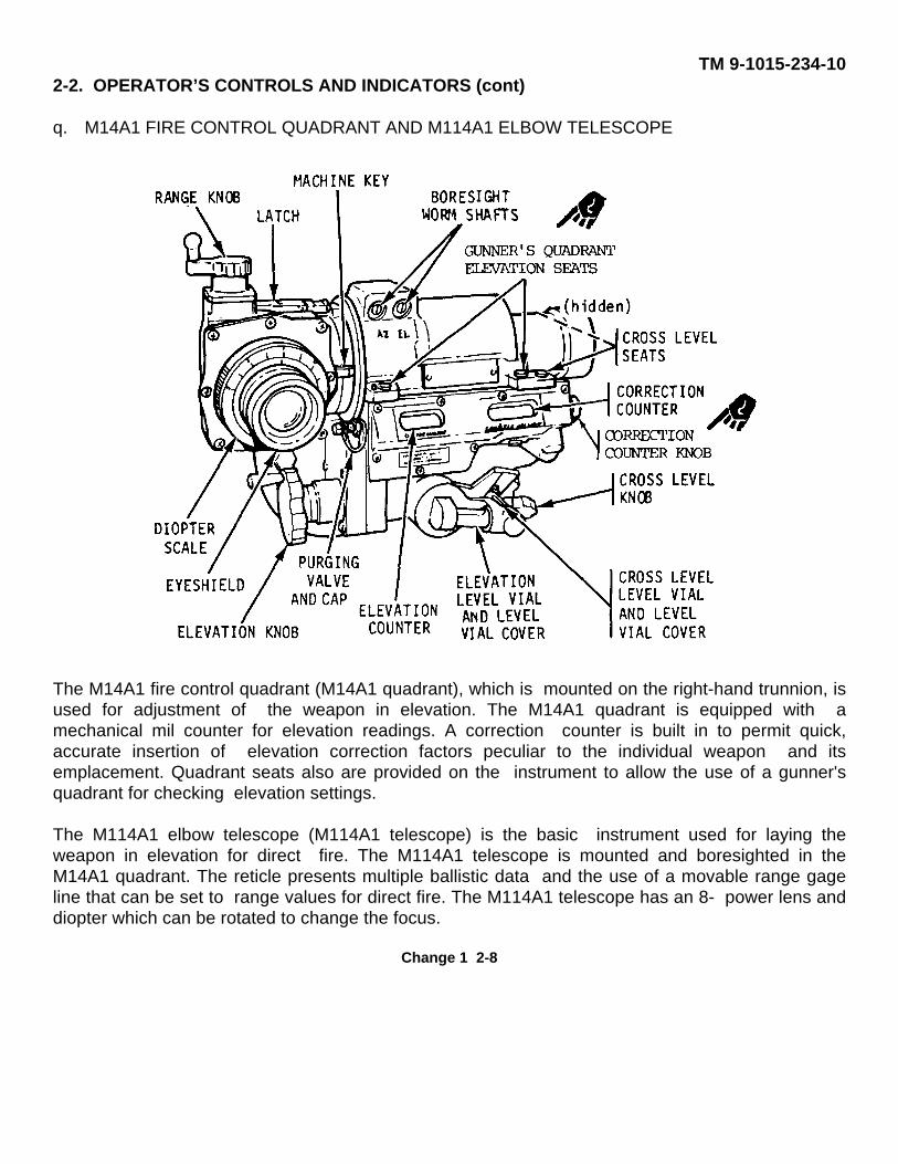
q. M14A1 FIRE CONTROL QUADRANT AND M114A1 ELBOW TELESCOPE
The M14A1 fire control quadrant (M14A1 quadrant), which is mounted on the right-hand trunnion, isused for adjustment of the weapon in elevation. The M14A1 quadrant is equipped with amechanical mil counter for elevation readings. A correction counter is built in to permit quick,accurate insertion of elevation correction factors peculiar to the individual weapon and itsemplacement. Quadrant seats also are provided on the instrument to allow the use of a gunner'squadrant for checking elevation settings.
The M114A1 elbow telescope (M114A1 telescope) is the basic instrument used for laying theweapon in elevation for direct fire. The M114A1 telescope is mounted and boresighted in theM14A1 quadrant. The reticle presents multiple ballistic data and the use of a movable range gageline that can be set to range values for direct fire. The M114A1 telescope has an 8- power lens anddiopter which can be rotated to change the focus.
Change 1 2-8
TM 9-1015-234-10
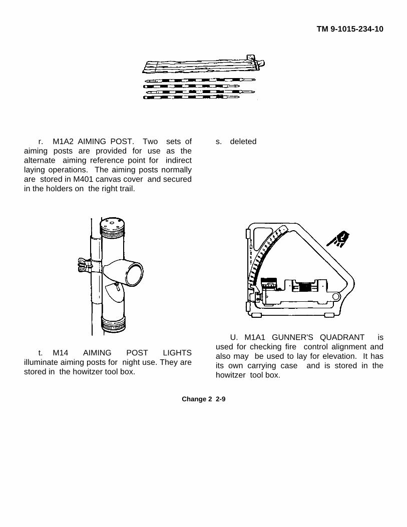
r. M1A2 AIMING POST. Two sets ofaiming posts are provided for use as thealternate aiming reference point for indirectlaying operations. The aiming posts normallyare stored in M401 canvas cover and securedin the holders on the right trail.
s. deleted
t. M14 AIMING POST LIGHTSilluminate aiming posts for night use. They arestored in the howitzer tool box.
U. M1A1 GUNNER'S QUADRANT isused for checking fire control alignment andalso may be used to lay for elevation. It hasits own carrying case and is stored in thehowitzer tool box.
Change 2 2-9
TM 9-1015-234-10
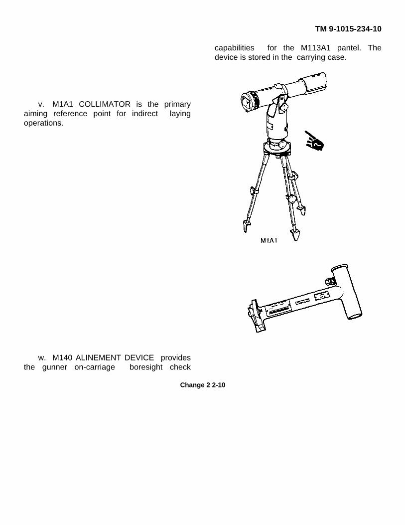
v. M1A1 COLLIMATOR is the primaryaiming reference point for indirect layingoperations.
w. M140 ALINEMENT DEVICE providesthe gunner on-carriage boresight check
capabilities for the M113A1 pantel. Thedevice is stored in the carrying case.
Change 2 2-10

TM 9-1015-234-10
Section II. PREVENTIVE MAINTENANCE CHECKS AND SERVICES (PMCS)
2-3.GENERAL
a. General. Your PMCS table (Table 2-1) has been provided so you can keep your equipmentin good operating condition and ready for its primary mission.
b. Warnings and cautions. Always observe the WARNINGS and CAUTIONS appearing inyour PMCS table BEFORE, DURING, and ATEER you operate the equipment. The warnings andcautions appear before certain procedures. You must observe these WARNINGS and CAUTIONSto prevent serious injury to yourself and others or prevent your equipment from being damaged.
2-4.EXPLANATION OF TABLE ENTRIES
a. Item number column. Numbers in this column are for reference. When completing DA Form2404, Equipment Inspection and Maintenance Worksheet, include the item number for thecheck/service indicating a fault. Item numbers also appear in the order that you must do checks andservices for the intervals listed.
b. Interval column. This column tells you when you must do the procedure in the procedurecolumn. BEFORE procedures must be done before you operate or use the equipment for itsintended mission. DURING procedures must be done during the time you are operating or using theequipment for its intended mission. AFTER procedures must be done immediately after you haveoperated or used the equipment. When a check and service procedure is required for both weeklyand before intervals, it is not necessary to do the procedure twice.
c. Check/Service column. This column provides the location and the item to be checked orserviced. The item location is underlined.
d. Procedure column. This column gives the procedure you must do to check or service theitem listed in the Check/Service column to know if the equipment is ready or available for itsintended mission or for operation. You must do the procedure at the time stated in the intervalcolumn.
Change 1 2-11
TM 9-1015-234-10
2-4.EXPIANATICN OF TABL EIIES (cant)e. Not fully mission capable if: column. Information in this column tells you what faults will
keep your equipment from being capable of performing its primary mission. If you make check andservice procedures that show faults listed in this column, do not operate the equipment. Followstandard operating procedures for maintaining the equipment or reporting equipment failure.
NOTEThe M102 howitzer will not be mission capable if ROTH the M14A1 quadrant and the MlA1 gunner'squadrant are missing or inoperable. The M102 howitzer needs a quadrant to be mission capable.The M102 howitzer is mission capable as long as FITHER quadrant is available.
Table 2-1. Preventive Maintenance Checks and Services for M102 HowitzerLocation
Item Interval Item to Procedure Not FullyMissionNo. Check/ Capable If:
Service
1 Before DA FORM Chief of Section2408-4 Check to see if Weapon has
your weapon has not beenbeen borescoped borescopedwithin the past within 180180 days. days.
2 Before BASIC Make sure all basicISSUE issue items areITEMS present and are in
proper workingorder. (See OOEIand AAL, appendixB.)
I3 Before M37/M37A1 Check variable RecoilREOOIL recoil timing timing isMECHANISM on M37/M37A1 out of
recoil adjustment.mechanism.
Change 2 2-12
TM 9-1015-234-10
Table 2-1. Preventive Maintenance Checks and Services for M102 Howitzer (cont)
LocationItem Interval Item to Procedure Not FullyMissionNo. Check/ Capable If:
Service
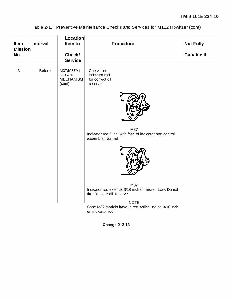
3 Before M37/M37A1 Check theRECOIL indicator rodMECHANISM for correct oil(cont) reserve.
M37Indicator rod flush with face of indicator and controlassembly: Normal.
M37Indicator rod extends 3/16 inch or more: Low. Do notfire. Restore oil reserve.
NOTESane M37 models have a red scribe line at 3/16 inchon indicator rod.
Change 2 2-13
TM 9-1015-234-10
Table 2-1. Preventive Maintenance Checks and Services for M102 Howitzer (cont)
LocationItem Interval Item to Procedure Not FullyMissionNo. Check/ Capable If:
Service
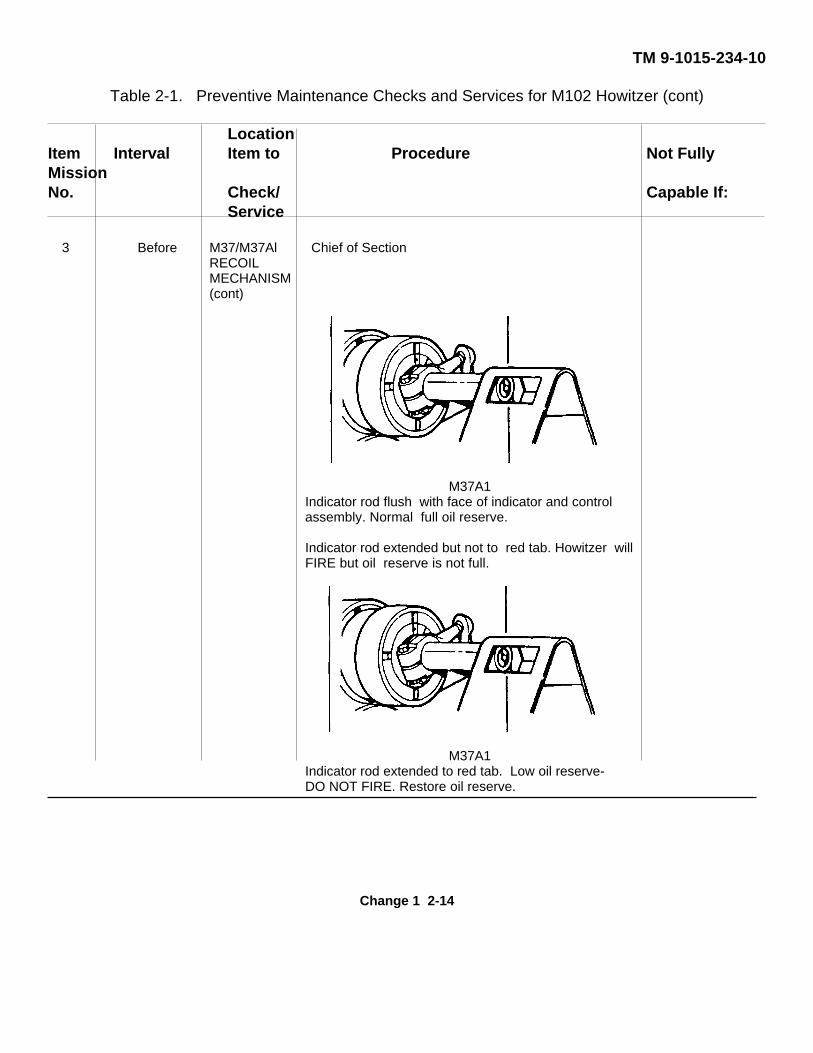
3 Before M37/M37Al Chief of SectionRECOILMECHANISM(cont)
M37A1Indicator rod flush with face of indicator and controlassembly. Normal full oil reserve.
Indicator rod extended but not to red tab. Howitzer willFIRE but oil reserve is not full.
M37A1Indicator rod extended to red tab. Low oil reserve-DO NOT FIRE. Restore oil reserve.
Change 1 2-14
TM 9-1015-234-10
Table 2-1. Preventive Maintenance Checks and Services for M102 Howitzer (cont)
LocationItem Interval Item to Procedure Not FullyMissionNo. Check/ Capable If:
Service
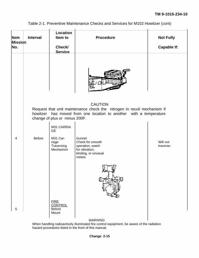
CAUTIONRequest that unit maintenance check the nitrogen in recoil mechanism ifhowitzer has moved from one location to another with a temperaturechange of plus or minus 200F.
M31 CARRIAGE
4 Before M31 Car- Gunnerriage Check for smooth Will notTraversing operation, watch traverse.Mechanism for vibration,
binding, or unusualnoises.
FIRECONTROL
5 BeforeMount
WARNINGWhen handling radioactively illuminated fire control equipment, be aware of the radiationhazard procedures listed in the front of this manual.
Change 2-15
TM 9-1015-234-10
Table 2-1. Preventive Maintenance Checks and Services for M102 Howitzer (cont)
LocationItem Interval Item to Procedure Not FullyMissionNo. Check/ Capable If:
Service
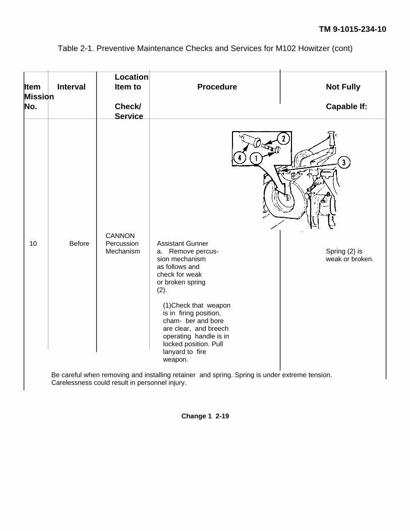
CANNON10 Before Percussion Assistant Gunner
Mechanism a. Remove percus- Spring (2) ission mechanism weak or broken.as follows andcheck for weakor broken spring(2).
(1)Check that weaponis in firing position,cham- ber and boreare clear, and breechoperating handle is inlocked position. Pulllanyard to fireweapon.
Be careful when removing and installing retainer and spring. Spring is under extreme tension.Carelessness could result in personnel injury.
Change 1 2-19
TM 9-1015-234-10
Table 2-1. Preventive Maintenance Checks and Services for M102 Howitzer (cont)
LocationItem Interval Item to Procedure Not FullyMissionNo. Check/ Capable If:
Service
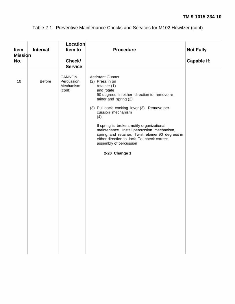
CANNON Assistant Gunner10 Before Percussion (2) Press in on
Mechanism retainer (1)(cont) and rotate
90 degrees in either direction to remove re-tainer and spring (2).
(3) Pull back cocking lever (3). Remove per-cussion mechanism(4).
If spring is broken, notify organizationalmaintenance. Install percussion mechanism,spring, and retainer. Twist retainer 90 degrees ineither direction to lock. To check correctassembly of percussion
2-20 Change 1
TM 9-1015-234-10Table 2-2. Preventive Maintenance Checks and Services
for M102 Howitzer (Cont’d)Location
Item Item to Crewmember Not Fully MissionNo. Interval Check/ Procedure Capable if:
Service
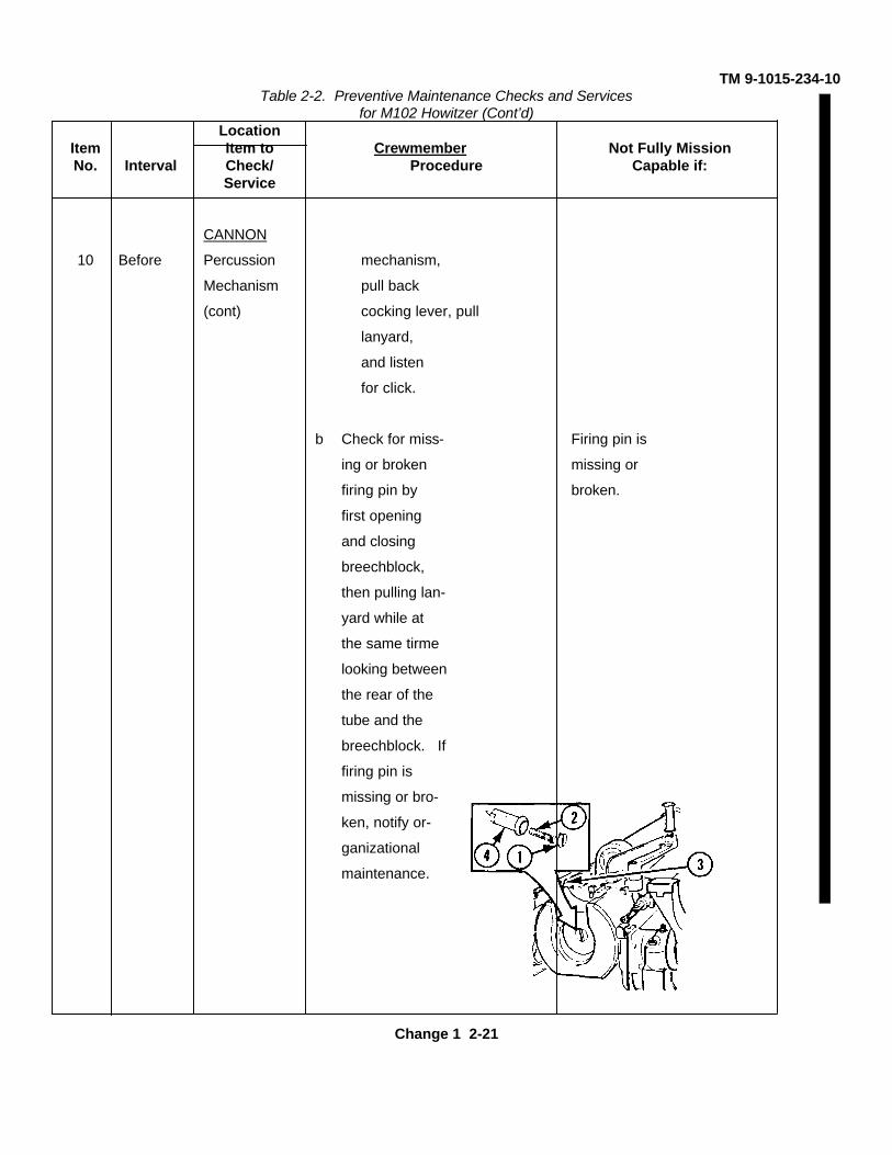
CANNON
10 Before Percussion mechanism,
Mechanism pull back
(cont) cocking lever, pull
lanyard,
and listen
for click.
b Check for miss- Firing pin is
ing or broken missing or
firing pin by broken.
first opening
and closing
breechblock,
then pulling lan-
yard while at
the same tirme
looking between
the rear of the
tube and the
breechblock. If
firing pin is
missing or bro-
ken, notify or-
ganizational
maintenance.
Change 1 2-21
TM 9-1015-234-10Table 2-2. Preventive Maintenance Checks and Services
for M102 Howitzer (Cont’d)Location
Item Item to Crewmember Not Fully MissionNo. Interval Check/ Procedure Capable if:
Service
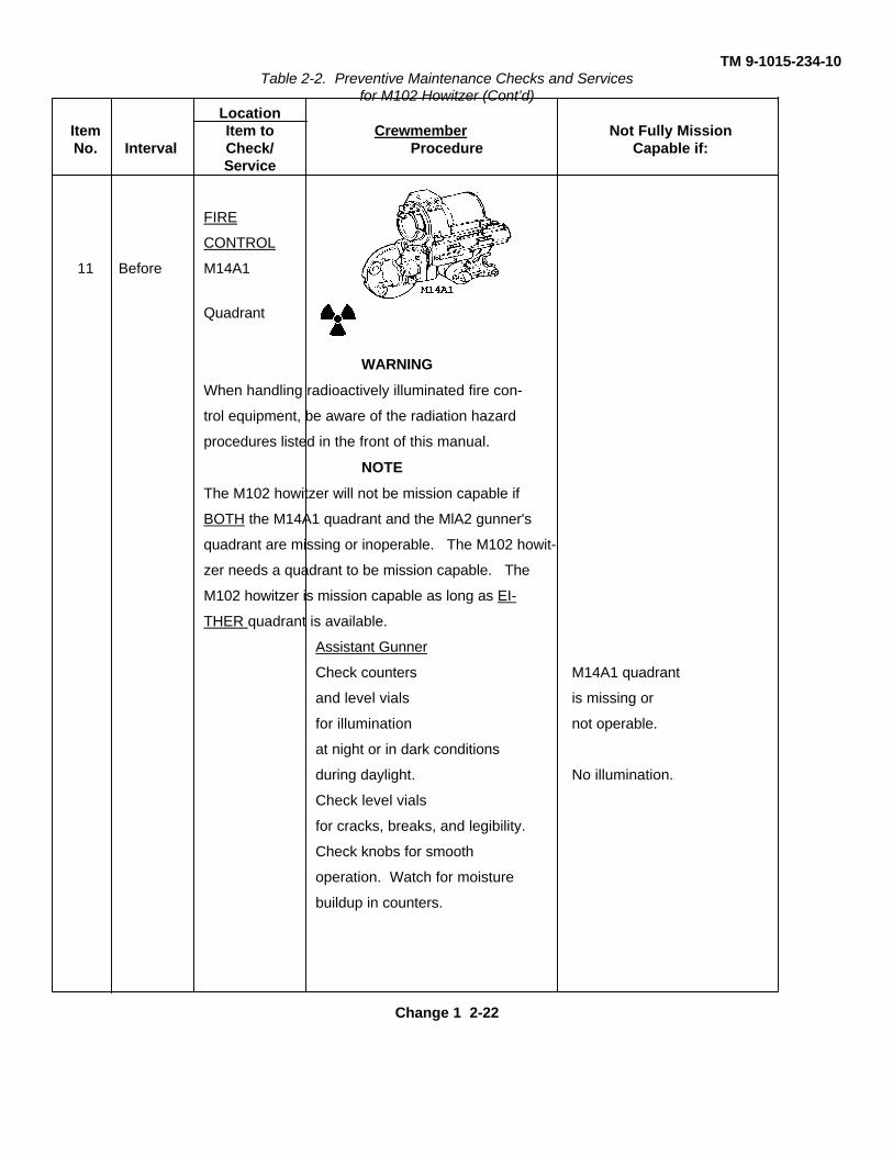
FIRE
CONTROL
11 Before M14A1
Quadrant
WARNING
When handling radioactively illuminated fire con-
trol equipment, be aware of the radiation hazard
procedures listed in the front of this manual.
NOTE
The M102 howitzer will not be mission capable if
BOTH the M14A1 quadrant and the MlA2 gunner's
quadrant are missing or inoperable. The M102 howit-
zer needs a quadrant to be mission capable. The
M102 howitzer is mission capable as long as EI-
THER quadrant is available.
Assistant Gunner
Check counters M14A1 quadrant
and level vials is missing or
for illumination not operable.
at night or in dark conditions
during daylight. No illumination.
Check level vials
for cracks, breaks, and legibility.
Check knobs for smooth
operation. Watch for moisture
buildup in counters.
Change 1 2-22
TM 9-1015-234-10Table 2-2. Preventive Maintenance Checks and Services
for M102 Howitzer (Cont’d)
LocationItem Item to Crewmember Not Fully MissionNo. Interval Check/ Procedure Capable if:
Service
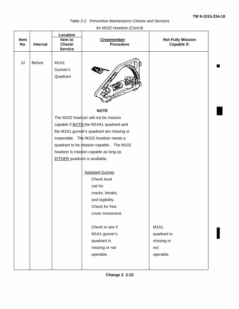
12 Before M1A1
Gunner's
Quadrant
NOTE
The M102 howitzer will not be mission
capable if BOTH the M14A1 quadrant and
the M1A1 gunner's quadrant are missing or
inoperable. The M102 howitzer needs a
quadrant to be mission capable. The M102
howitzer is mission capable as long as
EITHER quadrant is available.
Assistant Gunner
Check level
vial for
cracks, breaks,
and legibility.
Check for free
cover movement.
Check to see if M1A1
M1A1 gunner's quadrant is
quadrant is missing or
missing or not not
operable. operable.
Change 2 2-23
TM 9-1015-234-10Table 2-2. Preventive Maintenance Checks and Services
for M102 Howitzer (Cont’d)
LocationItem Item to Crewmember Not Fully MissionNo. Interval Check/ Procedure Capable if:
Service
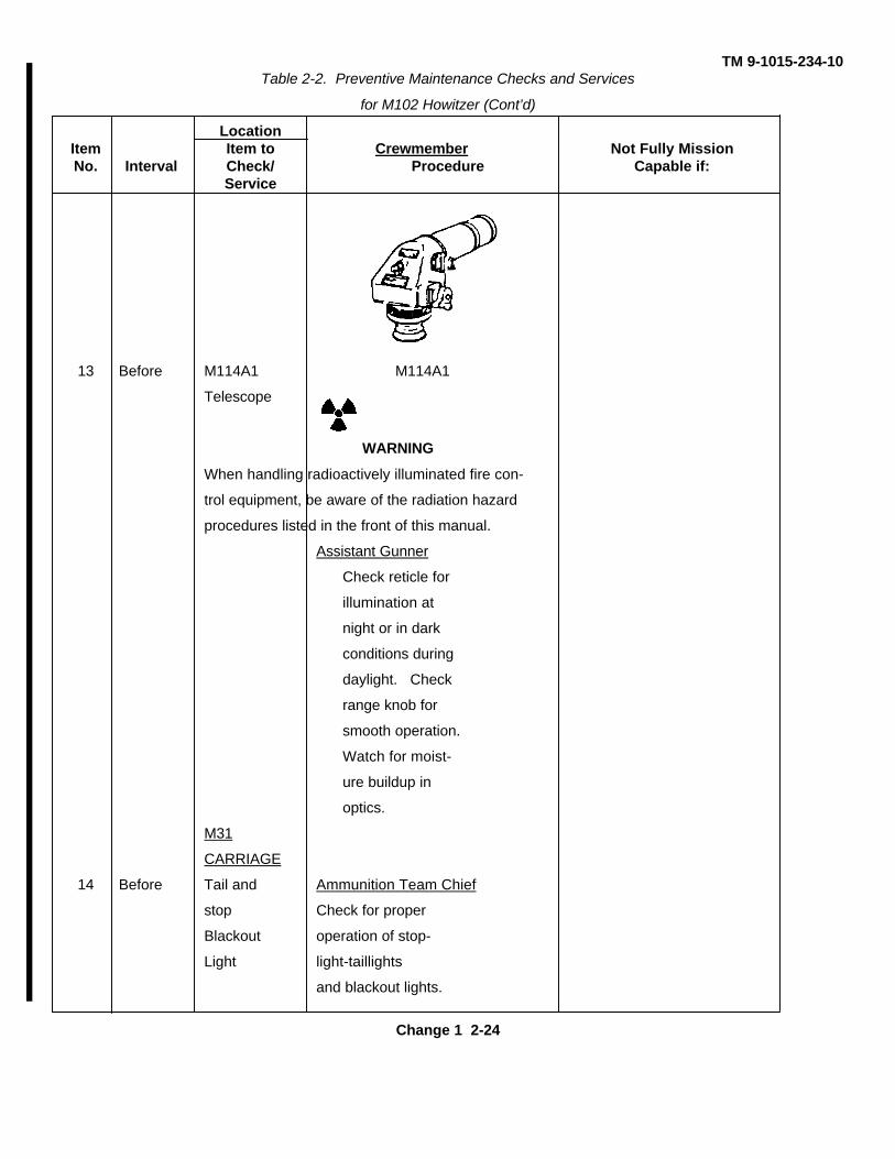
13 Before M114A1 M114A1
Telescope
WARNING
When handling radioactively illuminated fire con-
trol equipment, be aware of the radiation hazard
procedures listed in the front of this manual.
Assistant Gunner
Check reticle for
illumination at
night or in dark
conditions during
daylight. Check
range knob for
smooth operation.
Watch for moist-
ure buildup in
optics.
M31
CARRIAGE
14 Before Tail and Ammunition Team Chief
stop Check for proper
Blackout operation of stop-
Light light-taillights
and blackout lights.
Change 1 2-24
TM 9-1015-234-10Table 2-2. Preventive Maintenance Checks and Services
for M102 Howitzer (Cont’d)
LocationItem Item to Crewmember Not Fully MissionNo. Interval Check/ Procedure Capable if:
Service
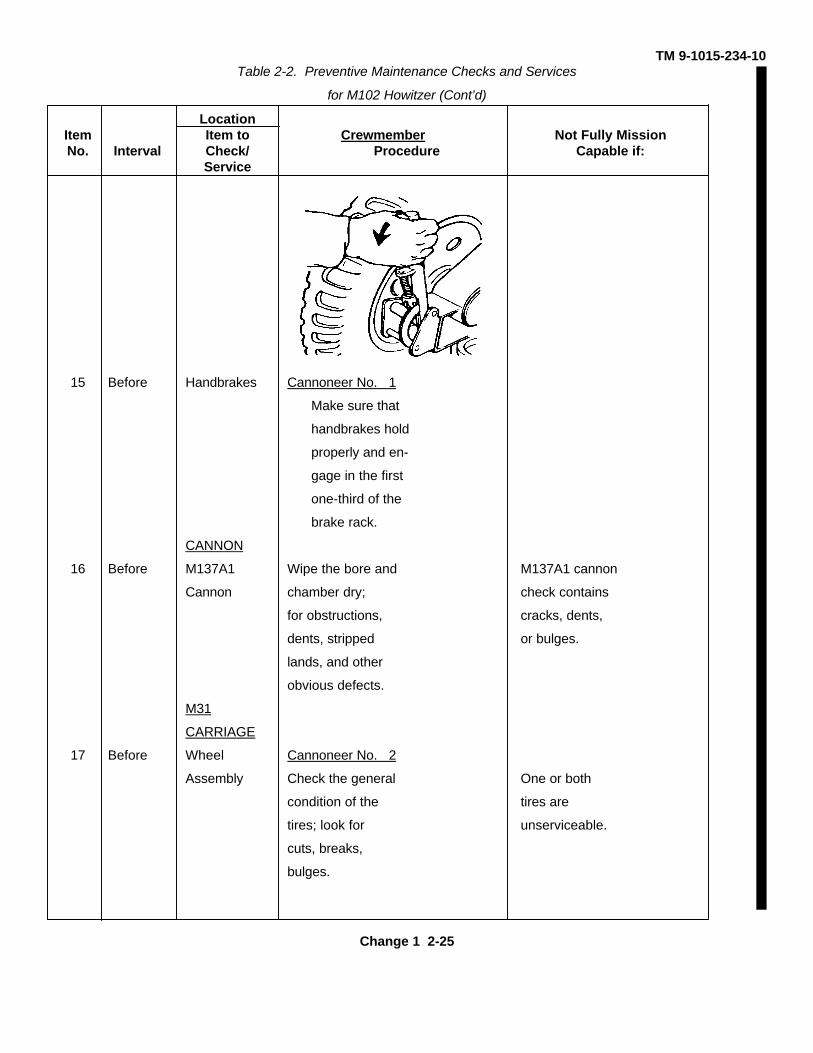
15 Before Handbrakes Cannoneer No. 1
Make sure that
handbrakes hold
properly and en-
gage in the first
one-third of the
brake rack.
CANNON
16 Before M137A1 Wipe the bore and M137A1 cannon
Cannon chamber dry; check contains
for obstructions, cracks, dents,
dents, stripped or bulges.
lands, and other
obvious defects.
M31
CARRIAGE
17 Before Wheel Cannoneer No. 2
Assembly Check the general One or both
condition of the tires are
tires; look for unserviceable.
cuts, breaks,
bulges.
Change 1 2-25
TM 9-1015-234-10Table 2-2. Preventive Maintenance Checks and Services
for M102 Howitzer (Cont’d)
LocationItem Item to Crewmember Not Fully MissionNo. Interval Check/ Procedure Capable if:
Service
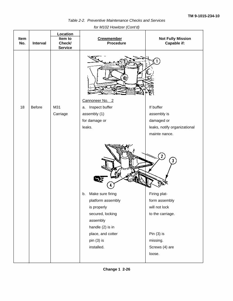
Cannoneer No. 2
18 Before M31 a. Inspect buffer If buffer
Carriage assembly (1) assembly is
for damage or damaged or
leaks. leaks, notify organizational
mainte nance.
b. Make sure firing Firing plat-
platform assembly form assembly
is properly will not lock
secured, locking to the carriage.
assembly
handle (2) is in
place, and cotter Pin (3) is
pin (3) is missing.
installed. Screws (4) are
loose.
Change 1 2-26
TM 9-1015-234-10Table 2-2. Preventive Maintenance Checks and Services
for M102 Howitzer (Cont’d)
LocationItem Item to Crewmember Not Fully MissionNo. Interval Check/ Procedure Capable if:
Service
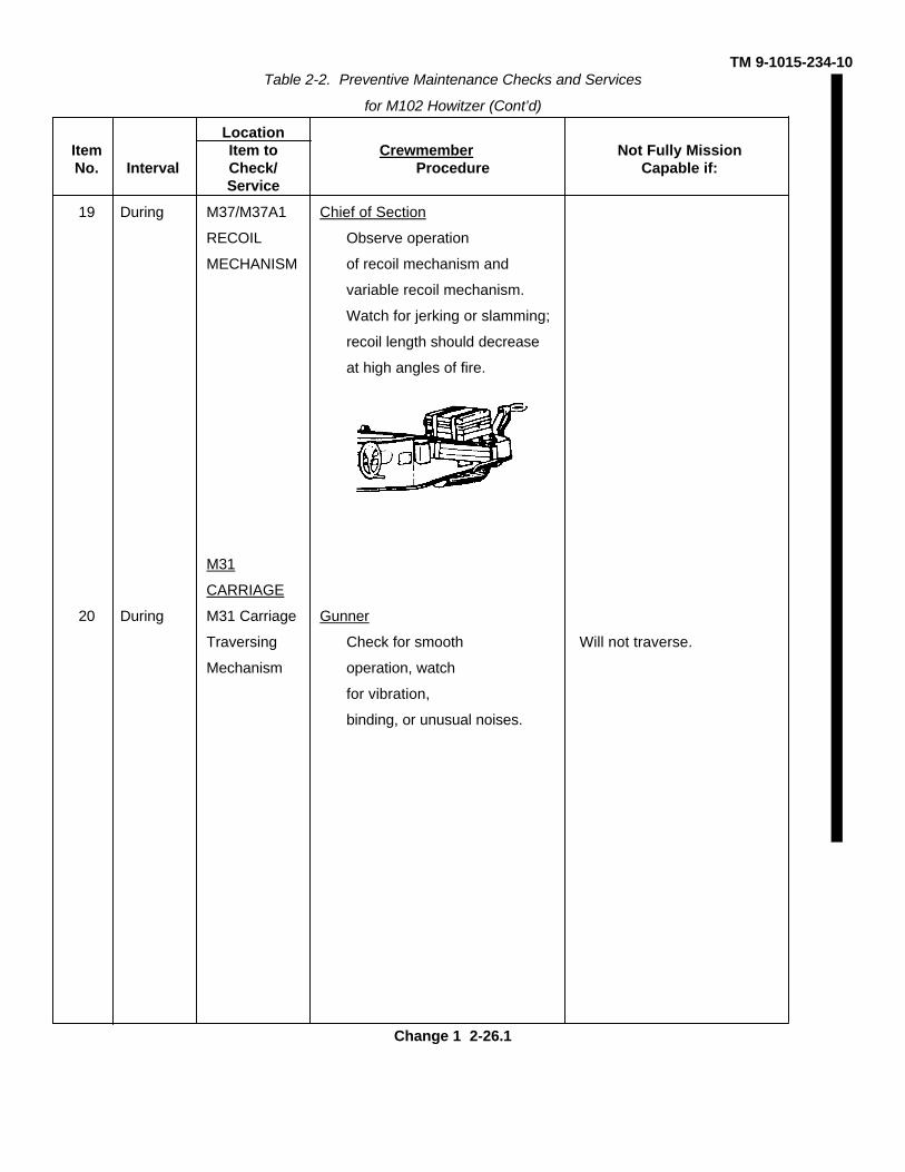
19 During M37/M37A1 Chief of Section
RECOIL Observe operation
MECHANISM of recoil mechanism and
variable recoil mechanism.
Watch for jerking or slamming;
recoil length should decrease
at high angles of fire.
M31
CARRIAGE
20 During M31 Carriage Gunner
Traversing Check for smooth Will not traverse.
Mechanism operation, watch
for vibration,
binding, or unusual noises.
Change 1 2-26.1
TM 9-1015-234-10Table 2-2. Preventive Maintenance Checks and Services
for M102 Howitzer (Cont’d)
LocationItem Item to Crewmember Not Fully MissionNo. Interval Check/ Procedure Capable if:
Service
M134A1
FIRE
CONTROL
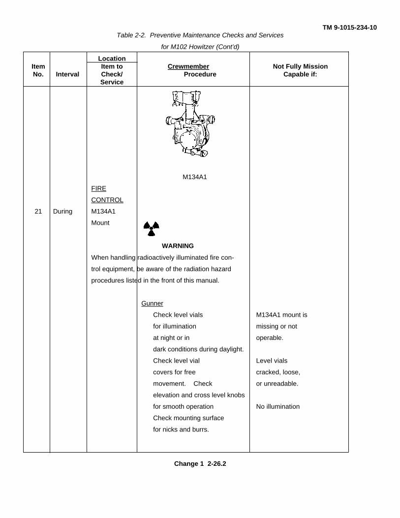
21 During M134A1
Mount
WARNING
When handling radioactively illuminated fire con-
trol equipment, be aware of the radiation hazard
procedures listed in the front of this manual.
Gunner
Check level vials M134A1 mount is
for illumination missing or not
at night or in operable.
dark conditions during daylight.
Check level vial Level vials
covers for free cracked, loose,
movement. Check or unreadable.
elevation and cross level knobs
for smooth operation No illumination
Check mounting surface
for nicks and burrs.
Change 1 2-26.2
TM 9-1015-234-10Table 2-2. Preventive Maintenance Checks and Services
for M102 Howitzer (Cont’d)
LocationItem Item to Crewmember Not Fully MissionNo. Interval Check/ Procedure Capable if:
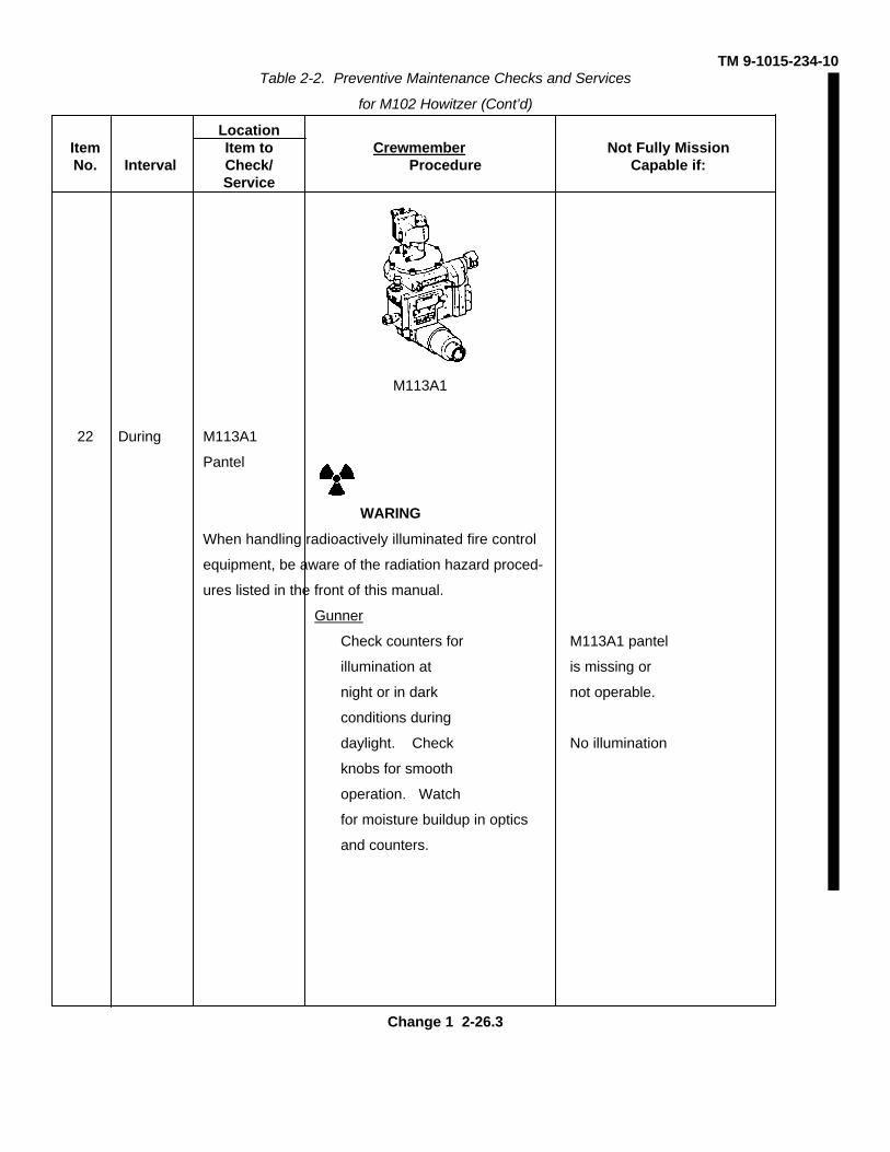
Service
M113A1
22 During M113A1
Pantel
WARING
When handling radioactively illuminated fire control
equipment, be aware of the radiation hazard proced-
ures listed in the front of this manual.
Gunner
Check counters for M113A1 pantel
illumination at is missing or
night or in dark not operable.
conditions during
daylight. Check No illumination
knobs for smooth
operation. Watch
for moisture buildup in optics
and counters.
Change 1 2-26.3
TM 9-1015-234-10Table 2-2. Preventive Maintenance Checks and Services
for M102 Howitzer (Cont’d)
LocationItem Item to Crewmember Not Fully MissionNo. Interval Check/ Procedure Capable if:
Service
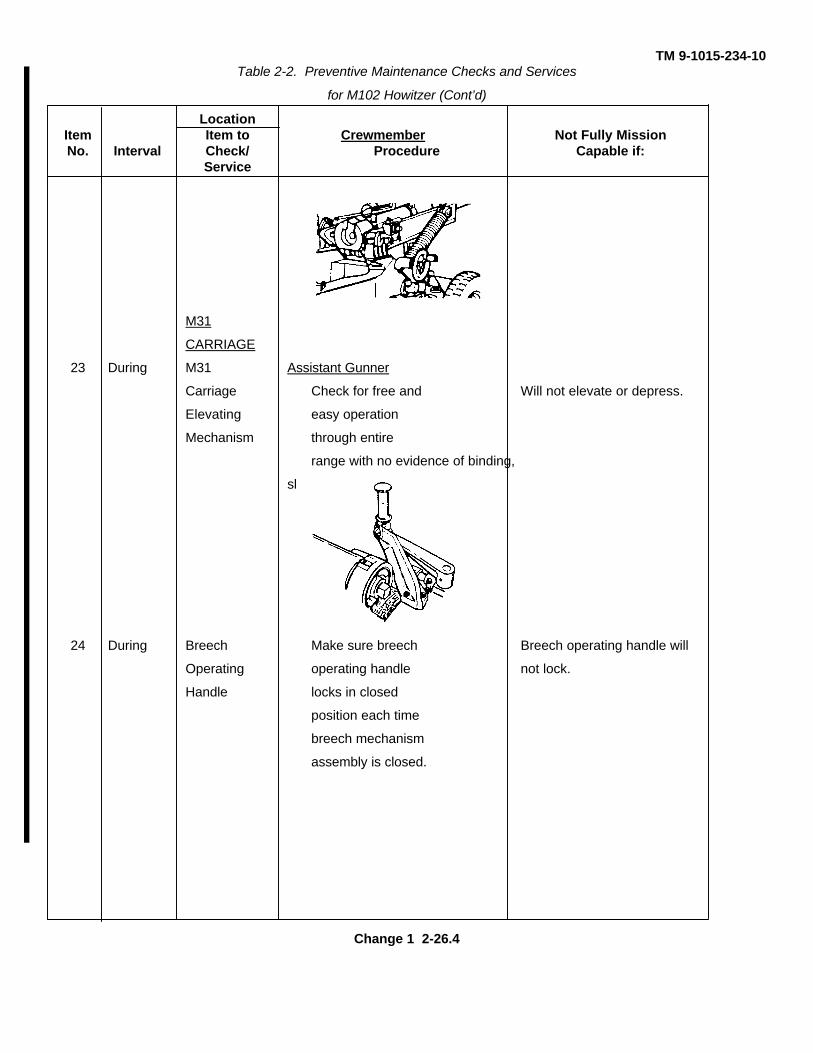
M31
CARRIAGE
23 During M31 Assistant Gunner
Carriage Check for free and Will not elevate or depress.
Elevating easy operation
Mechanism through entire
range with no evidence of binding,
slippage, or unusual noises.
24 During Breech Make sure breech Breech operating handle will
Operating operating handle not lock.
Handle locks in closed
position each time
breech mechanism
assembly is closed.
Change 1 2-26.4
TM 9-1015-234-10Table 2-2. Preventive Maintenance Checks and Services
for M102 Howitzer (Cont’d)
LocationItem Item to Crewmember Not Fully MissionNo. Interval Check/ Procedure Capable if:
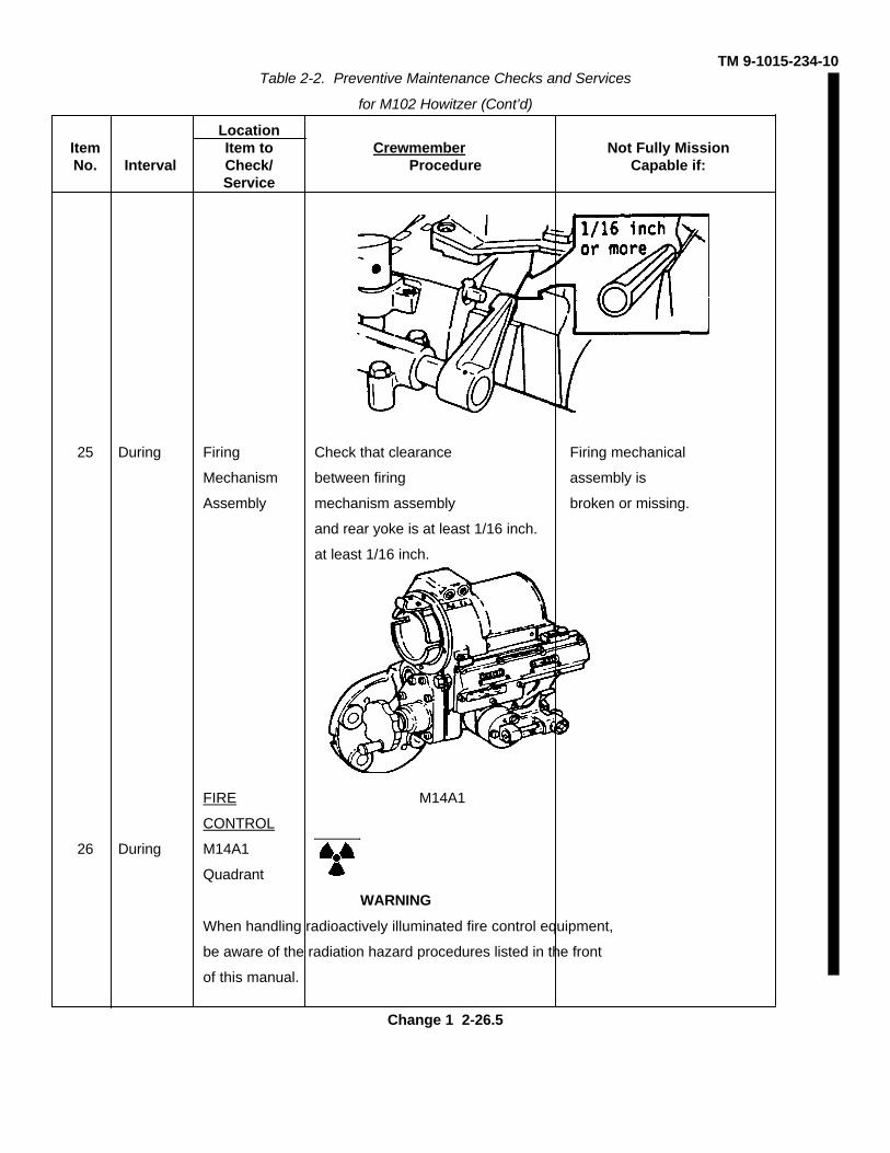
Service
25 During Firing Check that clearance Firing mechanical
Mechanism between firing assembly is
Assembly mechanism assembly broken or missing.
and rear yoke is at least 1/16 inch.
at least 1/16 inch.
FIRE M14A1
CONTROL
26 During M14A1
Quadrant
WARNING
When handling radioactively illuminated fire control equipment,
be aware of the radiation hazard procedures listed in the front
of this manual.
Change 1 2-26.5
TM 9-1015-234-10Table 2-2. Preventive Maintenance Checks and Services
for M102 Howitzer (Cont’d)
LocationItem Item to Crewmember Not Fully MissionNo. Interval Check/ Procedure Capable if:
Service
FIRE
CONTROL
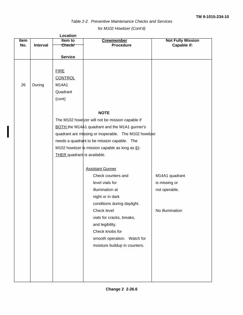
26 During M14A1
Quadrant
(cont)
NOTE
The M102 howitzer will not be mission capable if
BOTH the M14A1 quadrant and the M1A1 gunner's
quadrant are missing or inoperable. The M102 howitzer
needs a quadrant to be mission capable. The
M102 howitzer is mission capable as long as EI-
THER quadrant is available.
Assistant Gunner
Check counters and M14A1 quadrant
level vials for is missing or
illumination at not operable.
night or in dark
conditions during daylight.
Check level No illumination
vials for cracks, breaks,
and legibility.
Check knobs for
smooth operation. Watch for
moisture buildup in counters.
Change 2 2-26.6
TM 9-1015-234-10Table 2-2. Preventive Maintenance Checks and Services
for M102 Howitzer (Cont’d)
LocationItem Item to Crewmember Not Fully MissionNo. Interval Check/ Procedure Capable if:
Service
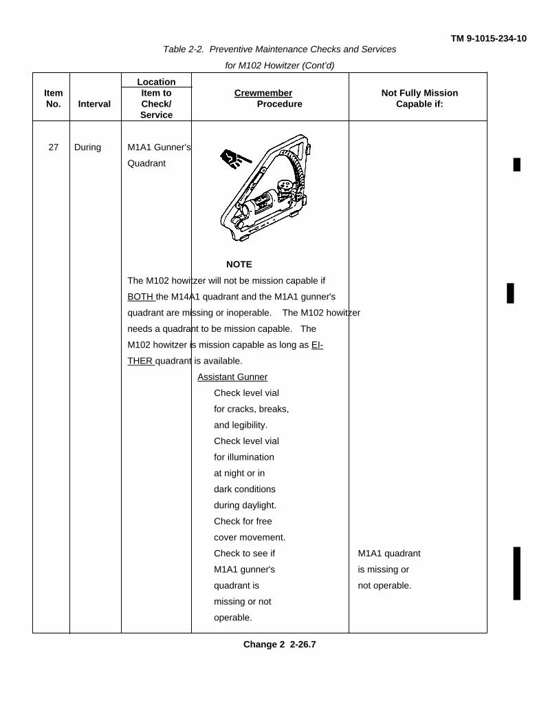
27 During M1A1 Gunner’s
Quadrant
NOTE
The M102 howitzer will not be mission capable if
BOTH the M14A1 quadrant and the M1A1 gunner's
quadrant are missing or inoperable. The M102 howitzer
needs a quadrant to be mission capable. The
M102 howitzer is mission capable as long as EI-
THER quadrant is available.
Assistant Gunner
Check level vial
for cracks, breaks,
and legibility.
Check level vial
for illumination
at night or in
dark conditions
during daylight.
Check for free
cover movement.
Check to see if M1A1 quadrant
M1A1 gunner's is missing or
quadrant is not operable.
missing or not
operable.
Change 2 2-26.7
TM 9-1015-234-10Table 2-2. Preventive Maintenance Checks and Services
for M102 Howitzer (Cont’d)
LocationItem Item to Crewmember Not Fully MissionNo. Interval Check/ Procedure Capable if:
Service
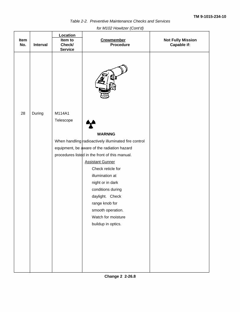
28 During M114A1
Telescope
WARNNG
When handling radioactively illuminated fire control
equipment, be aware of the radiation hazard
procedures listed in the front of this manual.
Assistant Gunner
Check reticle for
illumination at
night or in dark
conditions during
daylight. Check
range knob for
smooth operation.
Watch for moisture
buildup in optics.
Change 2 2-26.8
TM 9-1015-234-10Table 2-2. Preventive Maintenance Checks and Services
for M102 Howitzer (Cont’d)
LocationItem Item to Crewmember Not Fully MissionNo. Interval Check/ Procedure Capable if:
Service
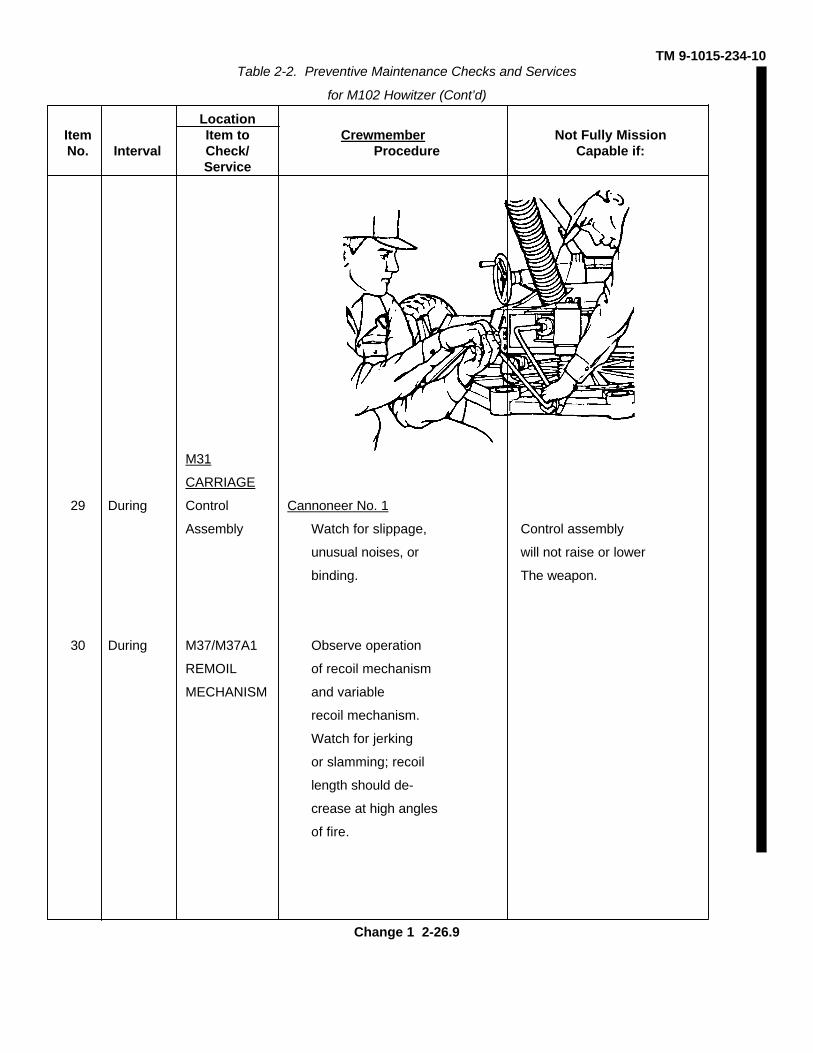
M31
CARRIAGE
29 During Control Cannoneer No. 1
Assembly Watch for slippage, Control assembly
unusual noises, or will not raise or lower
binding. The weapon.
30 During M37/M37A1 Observe operation
REMOIL of recoil mechanism
MECHANISM and variable
recoil mechanism.
Watch for jerking
or slamming; recoil
length should de-
crease at high angles
of fire.
Change 1 2-26.9
TM 9-1015-234-10Table 2-2. Preventive Maintenance Checks and Services
for M102 Howitzer (Cont’d)
LocationItem Item to Crewmember Not Fully MissionNo. Interval Check/ Procedure Capable if:
Service
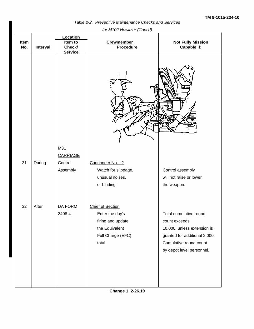
M31
CARRIAGE
31 During Control Cannoneer No. 2
Assembly Watch for slippage, Control assembly
unusual noises, will not raise or lower
or binding the weapon.
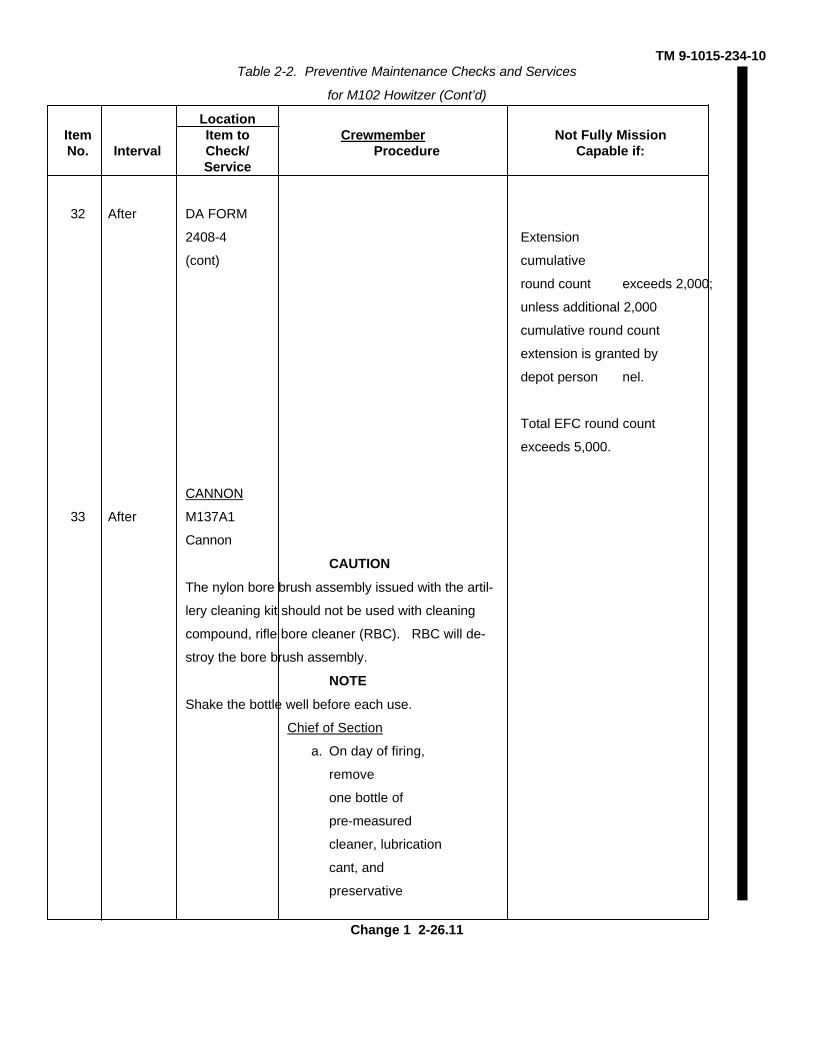
32 After DA FORM Chief of Section
2408-4 Enter the day's Total cumulative round
firing and update count exceeds
the Equivalent 10,000, unless extension is
Full Charge (EFC) granted for additional 2,000
total. Cumulative round count
by depot level personnel.
Change 1 2-26.10
TM 9-1015-234-10Table 2-2. Preventive Maintenance Checks and Services
for M102 Howitzer (Cont’d)
LocationItem Item to Crewmember Not Fully MissionNo. Interval Check/ Procedure Capable if:
Service
32 After DA FORM
2408-4 Extension
(cont) cumulative
round count exceeds 2,000;
unless additional 2,000
cumulative round count
extension is granted by
depot person nel.
Total EFC round count
exceeds 5,000.
CANNON
33 After M137A1
Cannon
CAUTION
The nylon bore brush assembly issued with the artil-
lery cleaning kit should not be used with cleaning
compound, rifle bore cleaner (RBC). RBC will de-
stroy the bore brush assembly.
NOTE
Shake the bottle well before each use.
Chief of Section
a. On day of firing,
remove
one bottle of
pre-measured
cleaner, lubrication
cant, and
preservative
Change 1 2-26.11
TM 9-1015-234-10Table 2-2. Preventive Maintenance Checks and Services
for M102 Howitzer (Cont’d)
LocationItem Item to Crewmember Not Fully MissionNo. Interval Check/ Procedure Capable if:
Service
CANNON
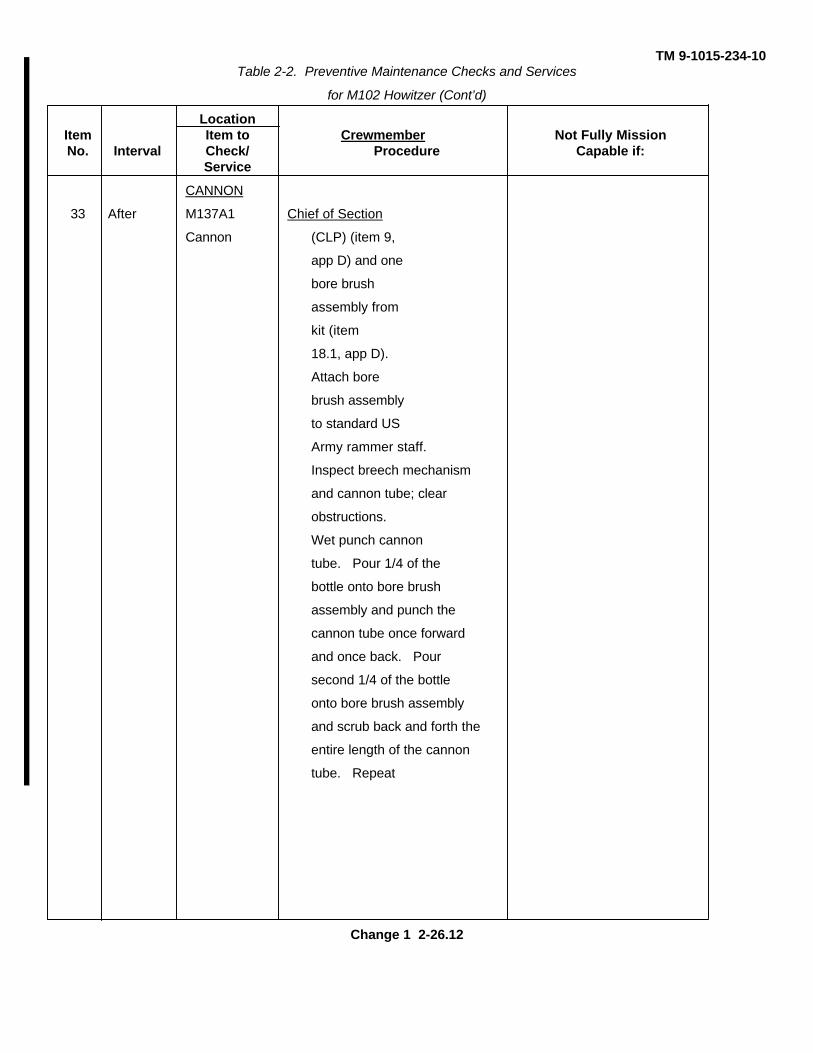
33 After M137A1 Chief of Section
Cannon (CLP) (item 9,
app D) and one
bore brush
assembly from
kit (item
18.1, app D).
Attach bore
brush assembly
to standard US
Army rammer staff.
Inspect breech mechanism
and cannon tube; clear
obstructions.
Wet punch cannon
tube. Pour 1/4 of the
bottle onto bore brush
assembly and punch the
cannon tube once forward
and once back. Pour
second 1/4 of the bottle
onto bore brush assembly
and scrub back and forth the
entire length of the cannon
tube. Repeat
Change 1 2-26.12
TM 9-1015-234-10Table 2-2. Preventive Maintenance Checks and Services
for M102 Howitzer (Cont’d)
LocationItem Item to Crewmember Not Fully MissionNo. Interval Check/ Procedure Capable if:
Service
CANNON
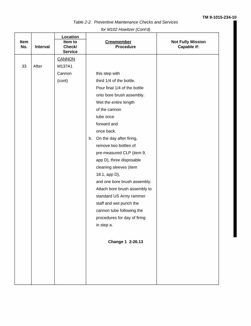
33 After M137A1
Cannon this step with
(cont) third 1/4 of the bottle.
Pour final 1/4 of the bottle
onto bore brush assembly.
Wet the entire length
of the cannon
tube once
forward and
once back.
b. On the day after firing,
remove two bottles of
pre-measured CLP (item 9,
app D), three disposable
cleaning sleeves (item
18.1, app D),
and one bore brush assembly.
Attach bore brush assembly to
standard US Army rammer
staff and wet punch the
cannon tube following the
procedures for day of firing
in step a.
Change 1 2-26.13

TM 9-1015-234-10Table 2-2. Preventive Maintenance Checks and Services
for M102 Howitzer (Cont’d)
LocationItem Item to Crewmember Not Fully MissionNo. Interval Check/ Procedure Capable if:
Service
CANNION
33 After M137A1 Chief of Section
Cannon above. Dry
(cont) punch cannon tube. Wrap
the bore brush assembly with
a new disposable cleaning
sleeve and dry punch the
entire length of the cannon
tube once forward and
once back. Remove and
dispose of the cleaning
sleeve. Wet punch cannon
tube. Wrap the bore brush
assembly with a new dispos-
able cleaning sleeve. Pour
on half a pre-measured
bottle. Wet punch the entire
length of the cannon
tube once forward and
once back. Remove and
dispose of cleaning sleeve.
Change 1 2-26.14
TM 9-1015-234-10Table 2-2. Preventive Maintenance Checks and Services
for M102 Howitzer (Cont’d)
LocationItem Item to Crewmember Not Fully MissionNo. Interval Check/ Procedure Capable if:
Service
CANNON
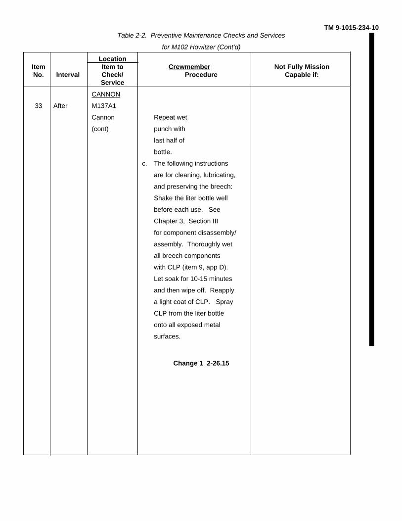
33 After M137A1
Cannon Repeat wet
(cont) punch with
last half of
bottle.
c. The following instructions
are for cleaning, lubricating,
and preserving the breech:
Shake the liter bottle well
before each use. See
Chapter 3, Section III
for component disassembly/
assembly. Thoroughly wet
all breech components
with CLP (item 9, app D).
Let soak for 10-15 minutes
and then wipe off. Reapply
a light coat of CLP. Spray
CLP from the liter bottle
onto all exposed metal
surfaces.
Change 1 2-26.15
TM 9-1015-234-10Table 2-2. Preventive Maintenance Checks and Services
for M102 Howitzer (Cont’d)
LocationItem Item to Crewmember Not Fully MissionNo. Interval Check/ Procedure Capable if:
Service
CANNON
33 After M137A1 Chief of Section
Cannon
(cont)
NOTE
If cannon tube has not been previously cleaned with
CLP and there is a heavy buildup of coppering or
carbon deposits, or severe heat cracking, it may be
necessary to repeat cleaning instructions until
cannon tube has been thoroughly cleaned with CLP.
M31
CARRIAGE
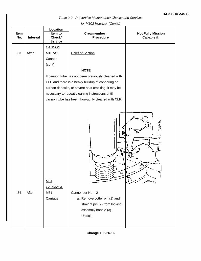
34 After M31 Cannoneer No. 2
Carriage a. Remove cotter pin (1) and
straight pin (2) from locking
assembly handle (3).
Unlock
Change 1 2-26.16
TM 9-1015-234-10Table 2-2. Preventive Maintenance Checks and Services
for M102 Howitzer (Cont’d)
LocationItem Item to Crewmember Not Fully MissionNo. Interval Check/ Procedure Capable if:
Service
M31
CARRIAGE
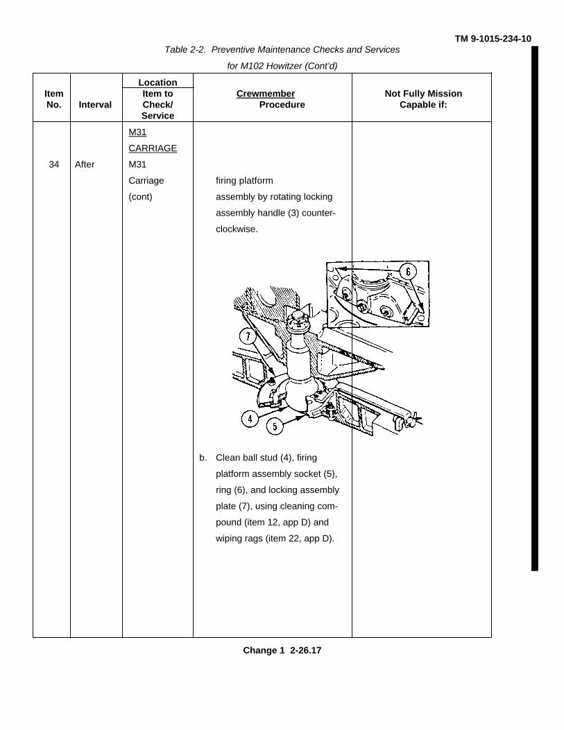
34 After M31
Carriage firing platform
(cont) assembly by rotating locking
assembly handle (3) counter-
clockwise.
b. Clean ball stud (4), firing
platform assembly socket (5),
ring (6), and locking assembly
plate (7), using cleaning com-
pound (item 12, app D) and
wiping rags (item 22, app D).
Change 1 2-26.17
TM 9-1015-234-10Table 2-2. Preventive Maintenance Checks and Services
for M102 Howitzer (Cont’d)
LocationItem Item to Crewmember Not Fully MissionNo. Interval Check/ Procedure Capable if:
Service
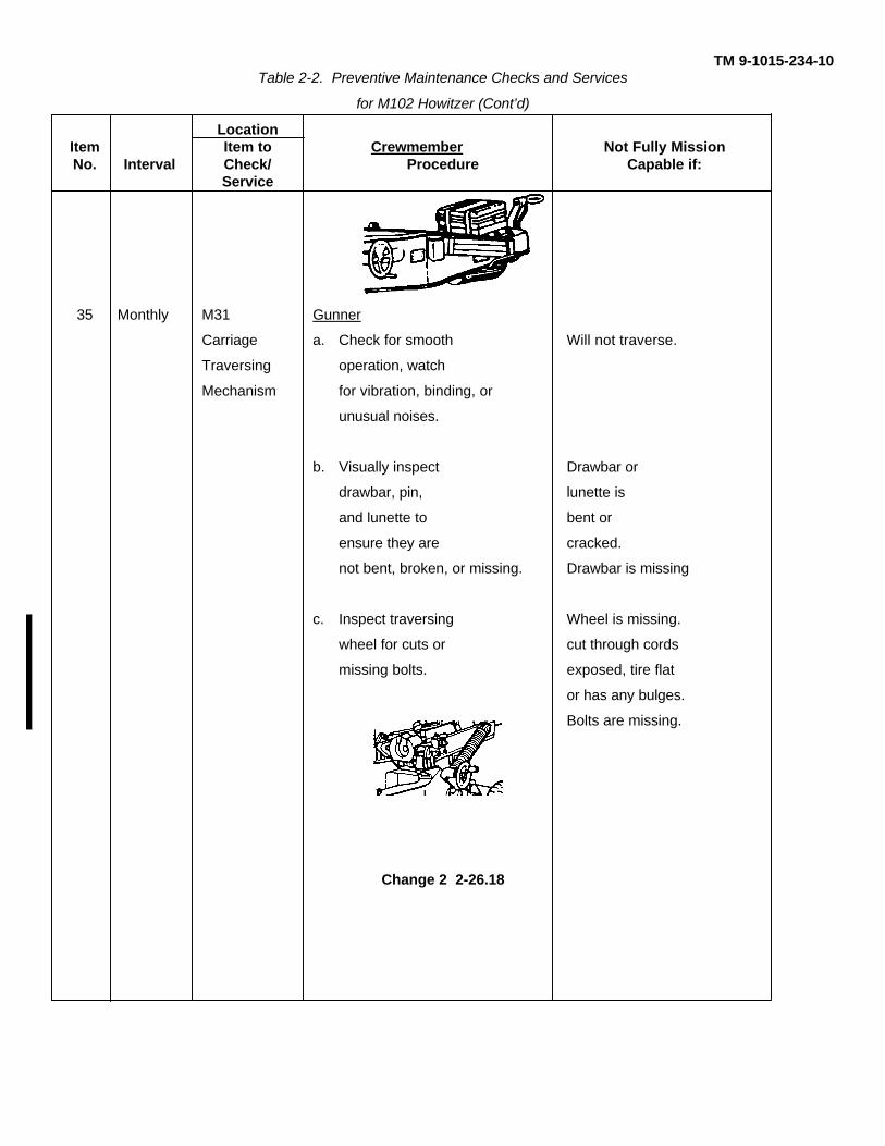
35 Monthly M31 Gunner
Carriage a. Check for smooth Will not traverse.
Traversing operation, watch
Mechanism for vibration, binding, or
unusual noises.
b. Visually inspect Drawbar or
drawbar, pin, lunette is
and lunette to bent or
ensure they are cracked.
not bent, broken, or missing. Drawbar is missing
c. Inspect traversing Wheel is missing.
wheel for cuts or cut through cords
missing bolts. exposed, tire flat
or has any bulges.
Bolts are missing.
Change 2 2-26.18
TM 9-1015-234-10Table 2-2. Preventive Maintenance Checks and Services
for M102 Howitzer (Cont’d)
LocationItem Item to Crewmember Not Fully MissionNo. Interval Check/ Procedure Capable if:
Service
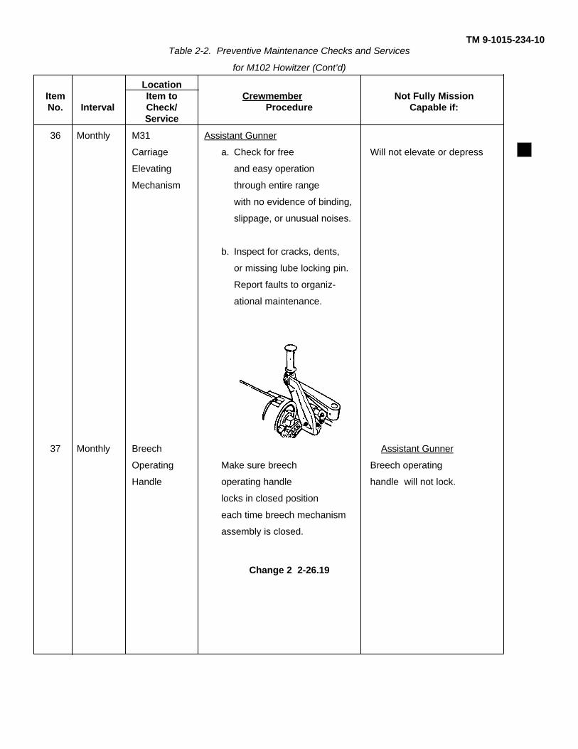
36 Monthly M31 Assistant Gunner
Carriage a. Check for free Will not elevate or depress
Elevating and easy operation
Mechanism through entire range
with no evidence of binding,
slippage, or unusual noises.
b. Inspect for cracks, dents,
or missing lube locking pin.
Report faults to organiz-
ational maintenance.
37 Monthly Breech Assistant Gunner
Operating Make sure breech Breech operating
Handle operating handle handle will not lock.
locks in closed position
each time breech mechanism
assembly is closed.
Change 2 2-26.19

TM 9-1015-234-10Table 2-2. Preventive Maintenance Checks and Services
for M102 Howitzer (Cont’d)
LocationItem Item to Crewmember Not Fully MissionNo. Interval Check/ Procedure Capable if:
Service
38 Monthly Wheel Cannoneer No. 2
Assembly a. Check for correct air pressure
(20 psi normally, 40 psi for long
movements on superhighways).
b. Check the wheel capnuts; if
they are loose, have them
torqued to 50-55 ft-lb.
c. Check tires; if they show wear
bars, notify organizational
maintenance.
Change 1 2-26.20
TM 9-1015-234-10
Section III. OPERATION UNDER USUAL CONDITIONS
WARNING
Do not store equipment of any kind inside the cannon tube. Foreign objects inadvertently left in bore ofcannon tube before firing can cause a premature explosion resulting in death or injury to personnel.
NOTE
Occupation of the firing section position is performed under the direct supervision of the chief ofsection. The prime mover should be driven into position so that the howitzer is aligned on the directionof fire.
2-5. DISCONNECTING M102 HOWITZER FROM PRIME MOVER
1 After the prime mover comes to a complete stop, the chief of section (CS) commands PREPARE TO DISMOUNT,DISMOUNT, or simply DISMOUNT.
2 Upon the command, DISMOUNT, the section personnel exit the rear of the prime mover.
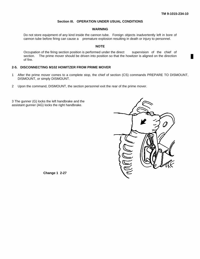
3 The gunner (G) locks the left handbrake and theassistant gunner (AG) locks the right handbrake.
Change 1 2-27
TM 9-1015-234-10
2-5. DISCONNECTING M102 HOWITZER FROM PRIME MOVER (cont)
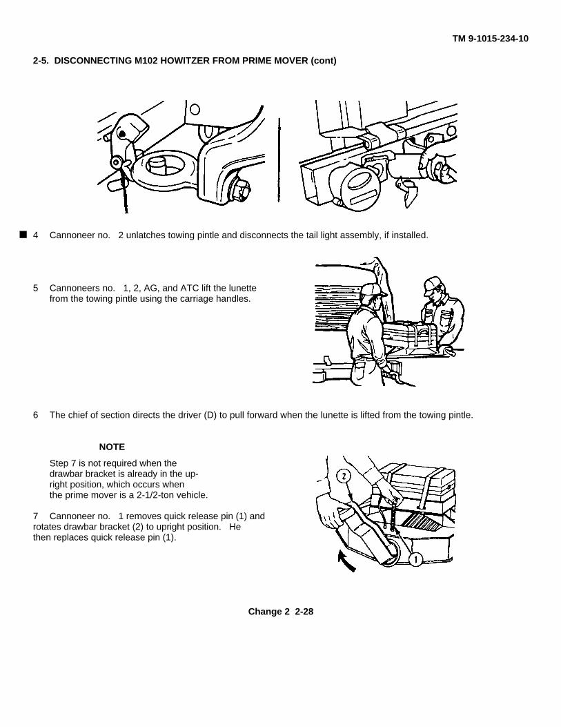
4 Cannoneer no. 2 unlatches towing pintle and disconnects the tail light assembly, if installed.
5 Cannoneers no. 1, 2, AG, and ATC lift the lunettefrom the towing pintle using the carriage handles.
6 The chief of section directs the driver (D) to pull forward when the lunette is lifted from the towing pintle.
NOTE
Step 7 is not required when thedrawbar bracket is already in the up-right position, which occurs whenthe prime mover is a 2-1/2-ton vehicle.
7 Cannoneer no. 1 removes quick release pin (1) androtates drawbar bracket (2) to upright position. Hethen replaces quick release pin (1).
Change 2 2-28
TM 9-1015-234-108. Cannoneer no. 2 removes tail and stop blackout lights by removing special pin.9. Assistant gunner and cannoneer no. 2 remove overall cover from the M102 howitzer.
2-6. EMPLACING M102 HOWITZER
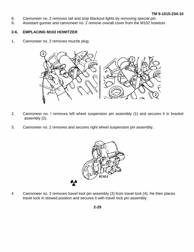
1. Cannoneer no. 2 removes muzzle plug.
2. Cannoneer no. I removes left wheel suspension pin assembly (1) and secures it in bracketassembly (2).
3. Cannoneer no. 2 removes and secures right wheel suspension pin assembly.
4 Cannoneer no. 2 removes travel lock pin assembly (3) from travel lock (4). He then placestravel lock in stowed position and secures it with travel lock pin assembly.
2-29
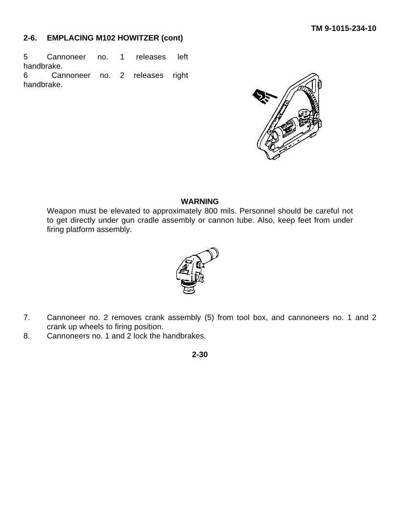
TM 9-1015-234-102-6. EMPLACING M102 HOWITZER (cont)
5 Cannoneer no. 1 releases lefthandbrake.6 Cannoneer no. 2 releases righthandbrake.
WARNINGWeapon must be elevated to approximately 800 mils. Personnel should be careful notto get directly under gun cradle assembly or cannon tube. Also, keep feet from underfiring platform assembly.
7. Cannoneer no. 2 removes crank assembly (5) from tool box, and cannoneers no. 1 and 2crank up wheels to firing position.
8. Cannoneers no. 1 and 2 lock the handbrakes.
2-30
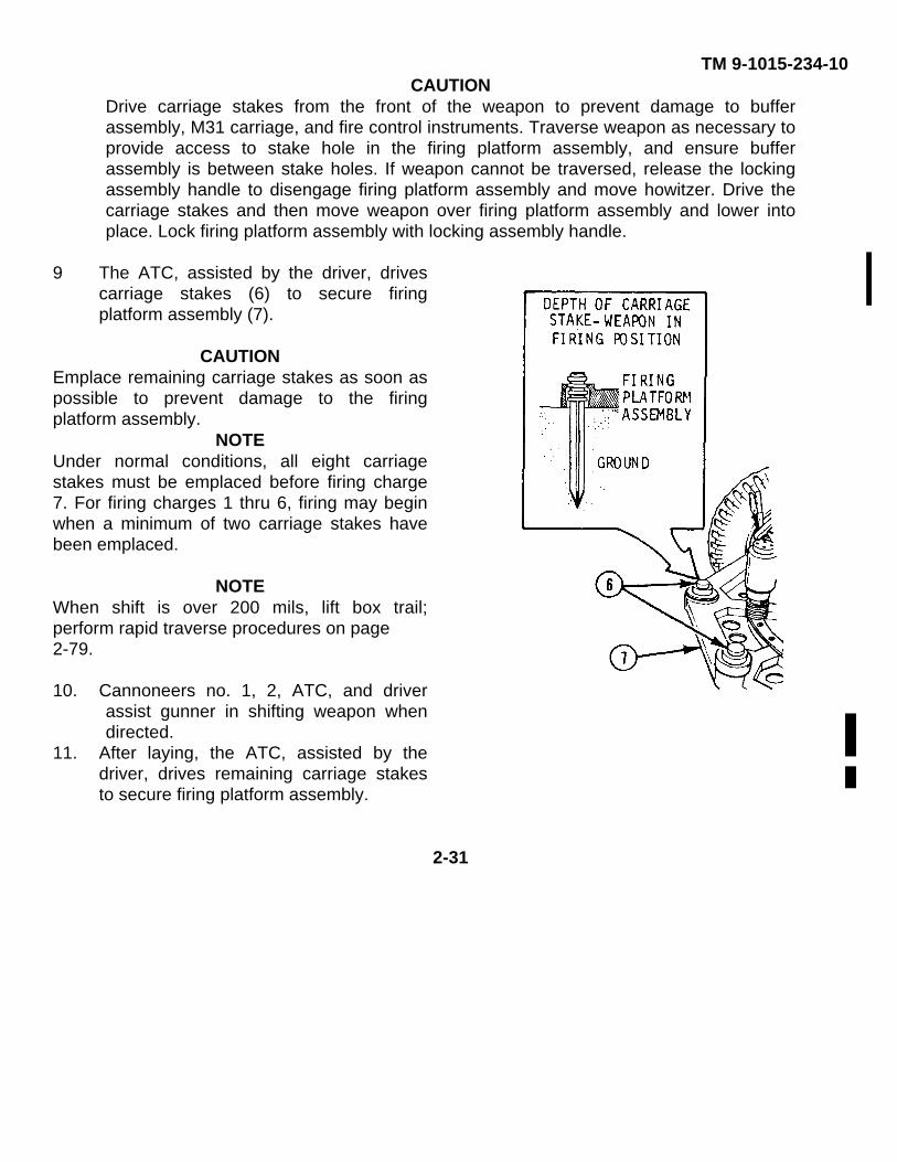
TM 9-1015-234-10CAUTION
Drive carriage stakes from the front of the weapon to prevent damage to bufferassembly, M31 carriage, and fire control instruments. Traverse weapon as necessary toprovide access to stake hole in the firing platform assembly, and ensure bufferassembly is between stake holes. If weapon cannot be traversed, release the lockingassembly handle to disengage firing platform assembly and move howitzer. Drive thecarriage stakes and then move weapon over firing platform assembly and lower intoplace. Lock firing platform assembly with locking assembly handle.
9 The ATC, assisted by the driver, drivescarriage stakes (6) to secure firingplatform assembly (7).
CAUTIONEmplace remaining carriage stakes as soon aspossible to prevent damage to the firingplatform assembly.
NOTEUnder normal conditions, all eight carriagestakes must be emplaced before firing charge7. For firing charges 1 thru 6, firing may beginwhen a minimum of two carriage stakes havebeen emplaced.
NOTEWhen shift is over 200 mils, lift box trail;perform rapid traverse procedures on page2-79.
10. Cannoneers no. 1, 2, ATC, and driverassist gunner in shifting weapon whendirected.
11. After laying, the ATC, assisted by thedriver, drives remaining carriage stakesto secure firing platform assembly.
2-31
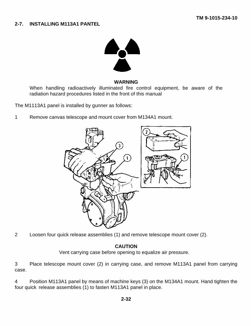
TM 9-1015-234-102-7. INSTALLING M113A1 PANTEL
WARNINGWhen handling radioactively illuminated fire control equipment, be aware of theradiation hazard procedures listed in the front of this manual
The M1113A1 panel is installed by gunner as follows:
1 Remove canvas telescope and mount cover from M134A1 mount.
2 Loosen four quick release assemblies (1) and remove telescope mount cover (2).
CAUTIONVent carrying case before opening to equalize air pressure.
3 Place telescope mount cover (2) in carrying case, and remove M113A1 panel from carryingcase.
4 Position M113A1 panel by means of machine keys (3) on the M134A1 mount. Hand tighten thefour quick release assemblies (1) to fasten M113A1 panel in place.
2-32
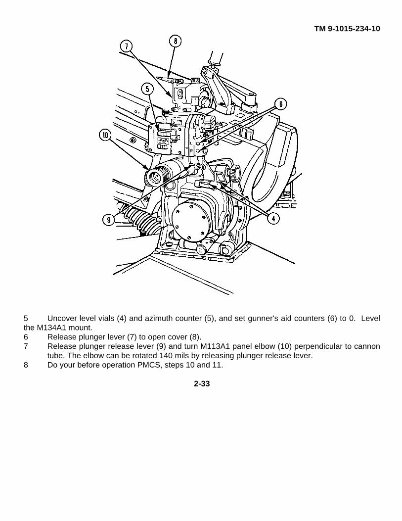
TM 9-1015-234-10
5 Uncover level vials (4) and azimuth counter (5), and set gunner's aid counters (6) to 0. Levelthe M134A1 mount.6 Release plunger lever (7) to open cover (8).7 Release plunger release lever (9) and turn M113A1 panel elbow (10) perpendicular to cannon
tube. The elbow can be rotated 140 mils by releasing plunger release lever.8 Do your before operation PMCS, steps 10 and 11.
2-33
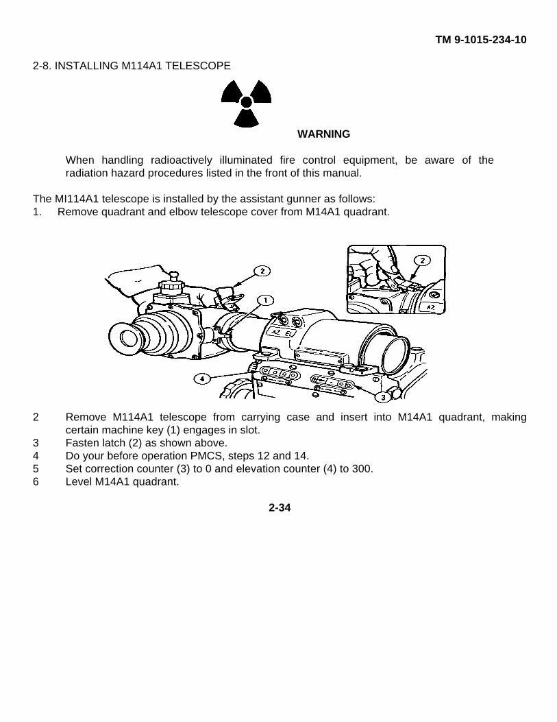
TM 9-1015-234-10
2-8. INSTALLING M114A1 TELESCOPE
WARNING
When handling radioactively illuminated fire control equipment, be aware of theradiation hazard procedures listed in the front of this manual.
The MI114A1 telescope is installed by the assistant gunner as follows:1. Remove quadrant and elbow telescope cover from M14A1 quadrant.
2 Remove M114A1 telescope from carrying case and insert into M14A1 quadrant, makingcertain machine key (1) engages in slot.
3 Fasten latch (2) as shown above.4 Do your before operation PMCS, steps 12 and 14.5 Set correction counter (3) to 0 and elevation counter (4) to 300.6 Level M14A1 quadrant.
2-34
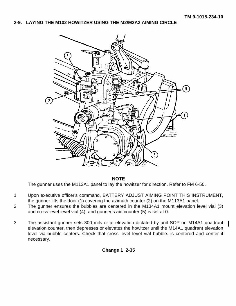
TM 9-1015-234-102-9. LAYING THE M102 HOWITZER USING THE M2/M2A2 AIMING CIRCLE
NOTEThe gunner uses the M113A1 panel to lay the howitzer for direction. Refer to FM 6-50.
1 Upon executive officer's command, BATTERY ADJUST AIMING POINT THIS INSTRUMENT,the gunner lifts the door (1) covering the azimuth counter (2) on the M113A1 panel.
2 The gunner ensures the bubbles are centered in the M134A1 mount elevation level vial (3)and cross level level vial (4), and gunner's aid counter (5) is set at 0.
3 The assistant gunner sets 300 mils or at elevation dictated by unit SOP on M14A1 quadrantelevation counter, then depresses or elevates the howitzer until the M14A1 quadrant elevationlevel via bubble centers. Check that cross level level vial bubble. is centered and center ifnecessary.
Change 1 2-35
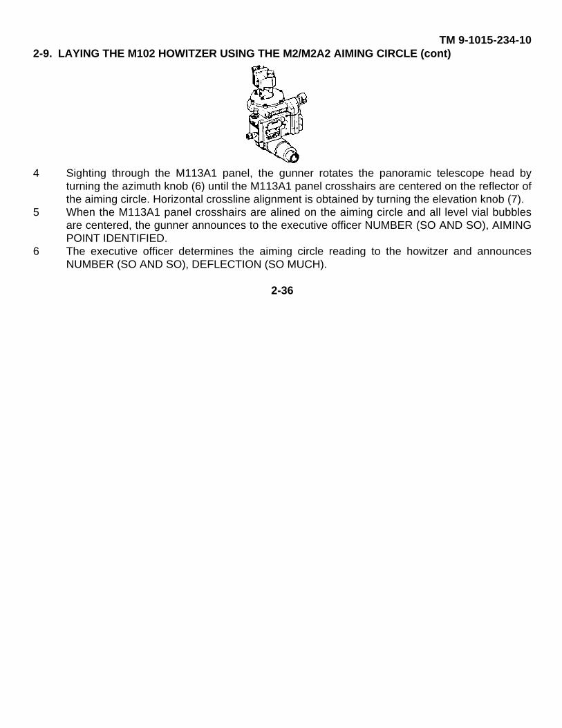
TM 9-1015-234-102-9. LAYING THE M102 HOWITZER USING THE M2/M2A2 AIMING CIRCLE (cont)
4 Sighting through the M113A1 panel, the gunner rotates the panoramic telescope head byturning the azimuth knob (6) until the M113A1 panel crosshairs are centered on the reflector ofthe aiming circle. Horizontal crossline alignment is obtained by turning the elevation knob (7).
5 When the M113A1 panel crosshairs are alined on the aiming circle and all level vial bubblesare centered, the gunner announces to the executive officer NUMBER (SO AND SO), AIMINGPOINT IDENTIFIED.
6 The executive officer determines the aiming circle reading to the howitzer and announcesNUMBER (SO AND SO), DEFLECTION (SO MUCH).
2-36
TM 9-1015-234-10
7 Upon announcement of the deflection, the gunner repeats the deflection by announcingNUMBER (SO AND SO), DEFLECTION (SO MUCH), and rotates the azimuth knob (6) untilthe announced deflection appears on the azimuth counter (2).
8 Operating the traversing handwheel assembly and sighting through the M113AI panel, thegunner traverses the weapon until the M113A1 panel crosshairs are centered on the reflectorof the aiming circle, ensuring that bubbles are centered in elevation level vial (3) and crosslevel level vial (4).
9 The gunner announces to the executive officer NUMBER (SO AND SO), READY FORRECHECK.10 The executive officer determines a new aiming circle reading to the howitzer and announces
NUMBER (SO AND SO), DEFLECTION (SO MUCH).11 Upon announcement of the new deflection, the gunner repeats the deflection and the
difference between the new deflection reading and the reading on the azimuth counter (2) tothe executive officer by saying NUMBER (SO AND SO), DEFLECTION (SO MUCH), (SOMANY) MILS.
12 The gunner then rotates the M113A1 panel azimuth knob (6) until the new deflection appearson the azimuth counter (2).
13 Operating the traversing handwheel assembly and sighting through the M113A1 panel, thegunner traverses the weapon until the M113A1 panel crosshairs are centered on the reflectorof the aiming circle with the bubbles centered in the M134A1 mount elevation level vial (3) andcross level level vial (4).
14 The gunner and executive officer repeat the recheck, steps 9 thru 13, until the differencebetween the aiming circle reading to the M113A1 panel and the reading on the azimuthcounter (2) is 0. The executive officer then announces NUMBER (SO AND SO) IS LAID.
15 Upon the command, LAID, the gunner records the value appearing on the azimuth counter (2).The cannon tube is now oriented for direction and should not be traversed until an aimingpoint is established.
2-37
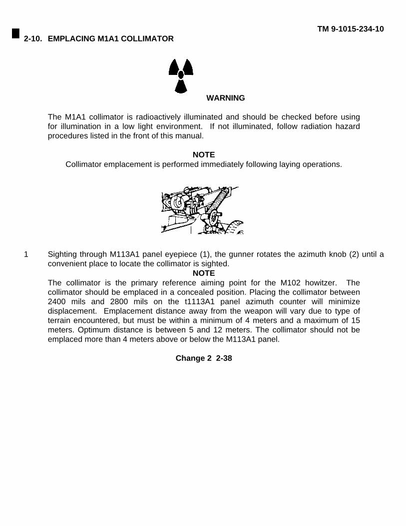
TM 9-1015-234-102-10. EMPLACING M1A1 COLLIMATOR
WARNING
The M1A1 collimator is radioactively illuminated and should be checked before usingfor illumination in a low light environment. If not illuminated, follow radiation hazardprocedures listed in the front of this manual.
NOTECollimator emplacement is performed immediately following laying operations.
1 Sighting through M113A1 panel eyepiece (1), the gunner rotates the azimuth knob (2) until aconvenient place to locate the collimator is sighted.
NOTEThe collimator is the primary reference aiming point for the M102 howitzer. Thecollimator should be emplaced in a concealed position. Placing the collimator between2400 mils and 2800 mils on the t1113A1 panel azimuth counter will minimizedisplacement. Emplacement distance away from the weapon will vary due to type ofterrain encountered, but must be within a minimum of 4 meters and a maximum of 15meters. Optimum distance is between 5 and 12 meters. The collimator should not beemplaced more than 4 meters above or below the M113A1 panel.
Change 2 2-38
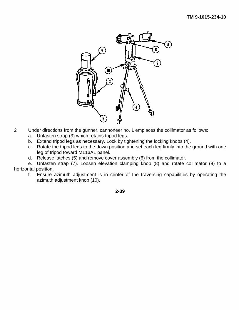
TM 9-1015-234-10
2 Under directions from the gunner, cannoneer no. 1 emplaces the collimator as follows:a. Unfasten strap (3) which retains tripod legs.b. Extend tripod legs as necessary. Lock by tightening the locking knobs (4).c. Rotate the tripod legs to the down position and set each leg firmly into the ground with one
leg of tripod toward M113A1 panel.d. Release latches (5) and remove cover assembly (6) from the collimator.e. Unfasten strap (7). Loosen elevation clamping knob (8) and rotate collimator (9) to a
horizontal position.f. Ensure azimuth adjustment is in center of the traversing capabilities by operating the
azimuth adjustment knob (10).
2-39
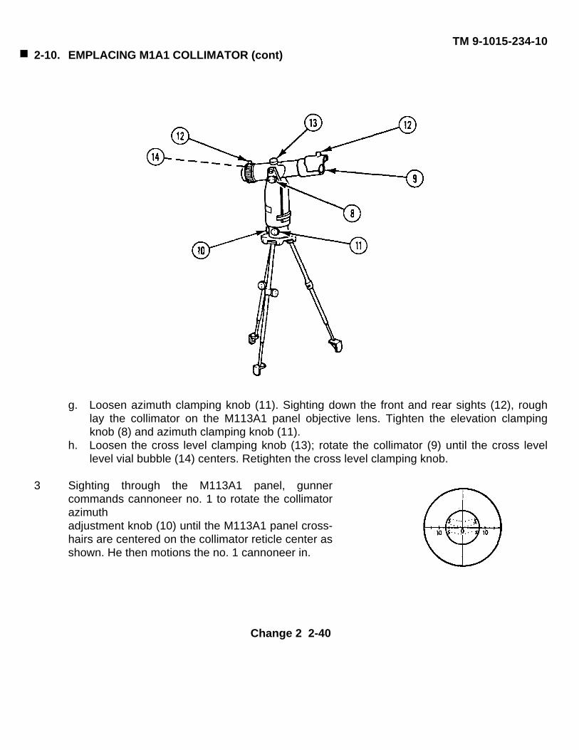
TM 9-1015-234-102-10. EMPLACING M1A1 COLLIMATOR (cont)
g. Loosen azimuth clamping knob (11). Sighting down the front and rear sights (12), roughlay the collimator on the M113A1 panel objective lens. Tighten the elevation clampingknob (8) and azimuth clamping knob (11).
h. Loosen the cross level clamping knob (13); rotate the collimator (9) until the cross levellevel vial bubble (14) centers. Retighten the cross level clamping knob.
3 Sighting through the M113A1 panel, gunnercommands cannoneer no. 1 to rotate the collimatorazimuthadjustment knob (10) until the M113A1 panel cross-hairs are centered on the collimator reticle center asshown. He then motions the no. 1 cannoneer in.
Change 2 2-40
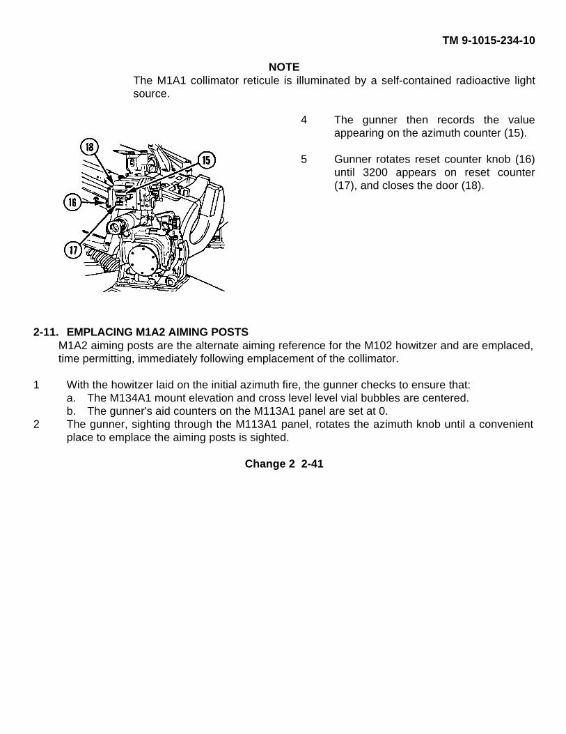
TM 9-1015-234-10
NOTEThe M1A1 collimator reticule is illuminated by a self-contained radioactive lightsource.
4 The gunner then records the valueappearing on the azimuth counter (15).
5 Gunner rotates reset counter knob (16)until 3200 appears on reset counter(17), and closes the door (18).
2-11. EMPLACING M1A2 AIMING POSTSM1A2 aiming posts are the alternate aiming reference for the M102 howitzer and are emplaced,time permitting, immediately following emplacement of the collimator.
1 With the howitzer laid on the initial azimuth fire, the gunner checks to ensure that:a. The M134A1 mount elevation and cross level level vial bubbles are centered.b. The gunner's aid counters on the M113A1 panel are set at 0.
2 The gunner, sighting through the M113A1 panel, rotates the azimuth knob until a convenientplace to emplace the aiming posts is sighted.
Change 2 2-41
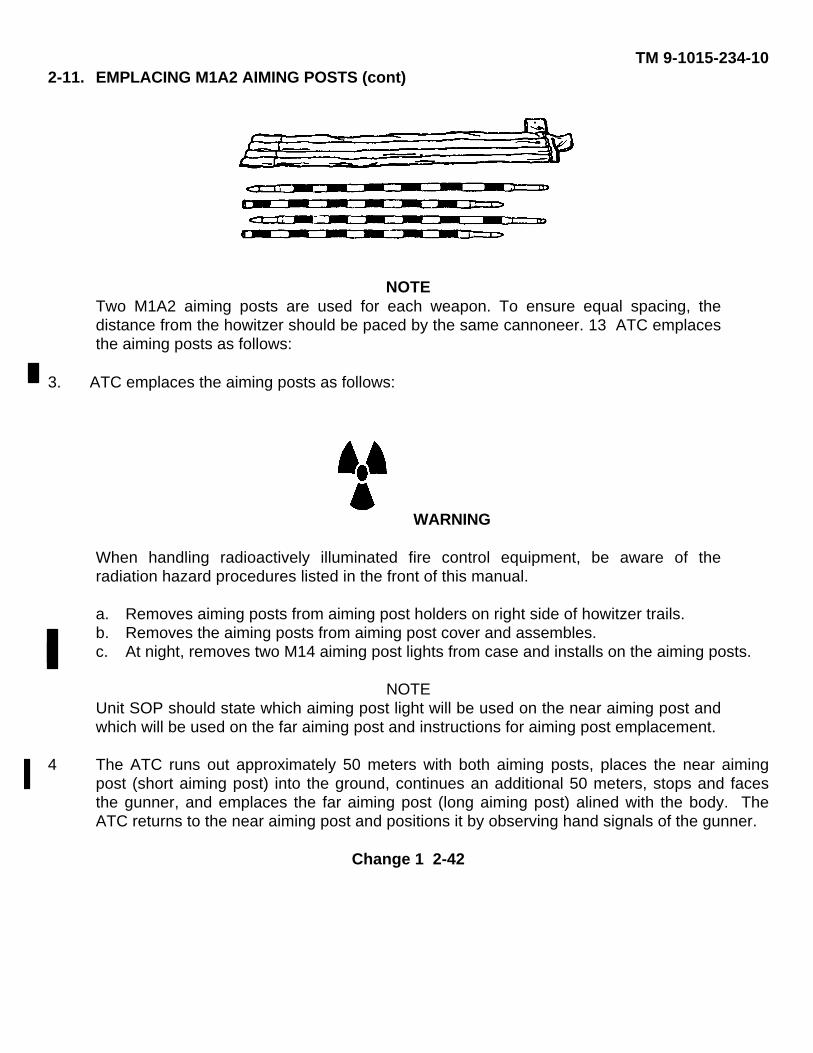
TM 9-1015-234-102-11. EMPLACING M1A2 AIMING POSTS (cont)
NOTETwo M1A2 aiming posts are used for each weapon. To ensure equal spacing, thedistance from the howitzer should be paced by the same cannoneer. 13 ATC emplacesthe aiming posts as follows:
3. ATC emplaces the aiming posts as follows:
WARNING
When handling radioactively illuminated fire control equipment, be aware of theradiation hazard procedures listed in the front of this manual.
a. Removes aiming posts from aiming post holders on right side of howitzer trails.b. Removes the aiming posts from aiming post cover and assembles.c. At night, removes two M14 aiming post lights from case and installs on the aiming posts.
NOTEUnit SOP should state which aiming post light will be used on the near aiming post andwhich will be used on the far aiming post and instructions for aiming post emplacement.
4 The ATC runs out approximately 50 meters with both aiming posts, places the near aimingpost (short aiming post) into the ground, continues an additional 50 meters, stops and facesthe gunner, and emplaces the far aiming post (long aiming post) alined with the body. TheATC returns to the near aiming post and positions it by observing hand signals of the gunner.
Change 1 2-42
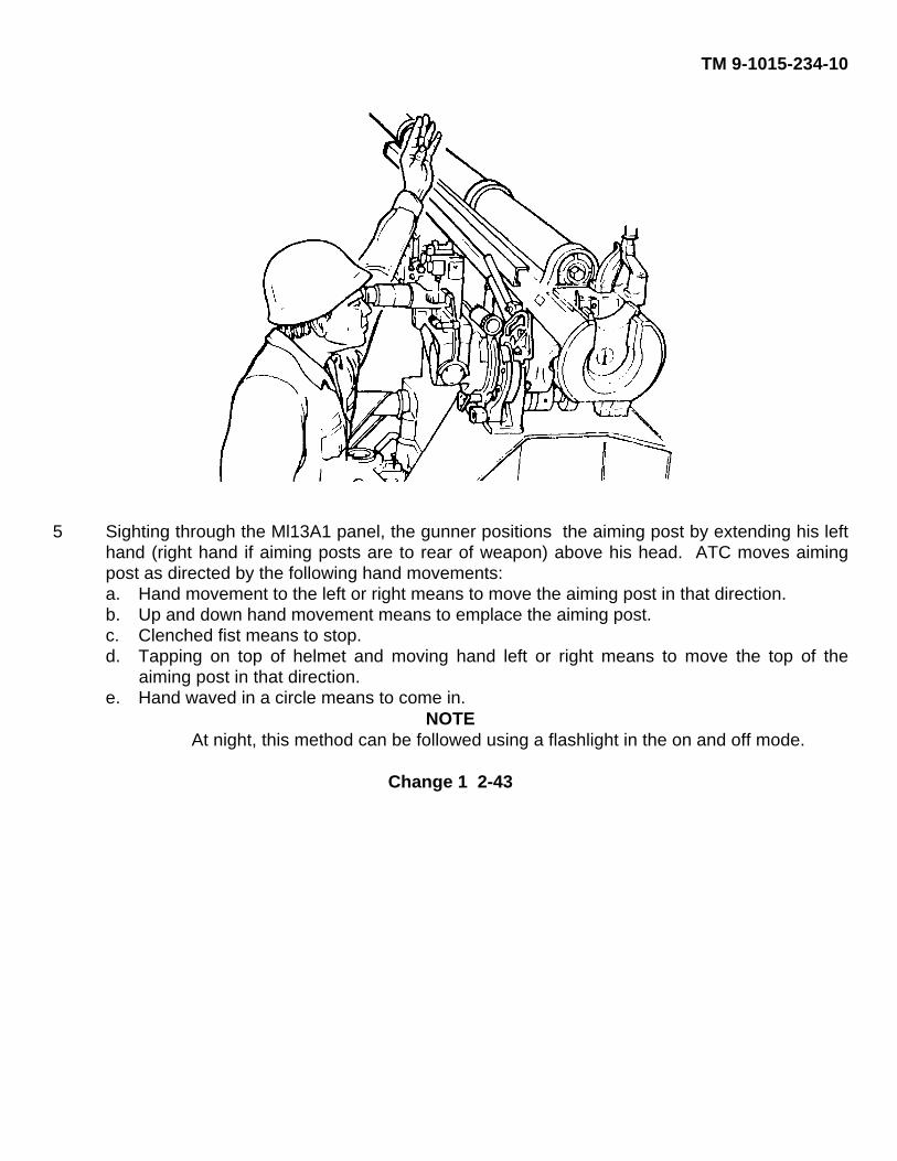
TM 9-1015-234-10
5 Sighting through the Ml13A1 panel, the gunner positions the aiming post by extending his lefthand (right hand if aiming posts are to rear of weapon) above his head. ATC moves aimingpost as directed by the following hand movements:a. Hand movement to the left or right means to move the aiming post in that direction.b. Up and down hand movement means to emplace the aiming post.c. Clenched fist means to stop.d. Tapping on top of helmet and moving hand left or right means to move the top of the
aiming post in that direction.e. Hand waved in a circle means to come in.
NOTEAt night, this method can be followed using a flashlight in the on and off mode.
Change 1 2-43
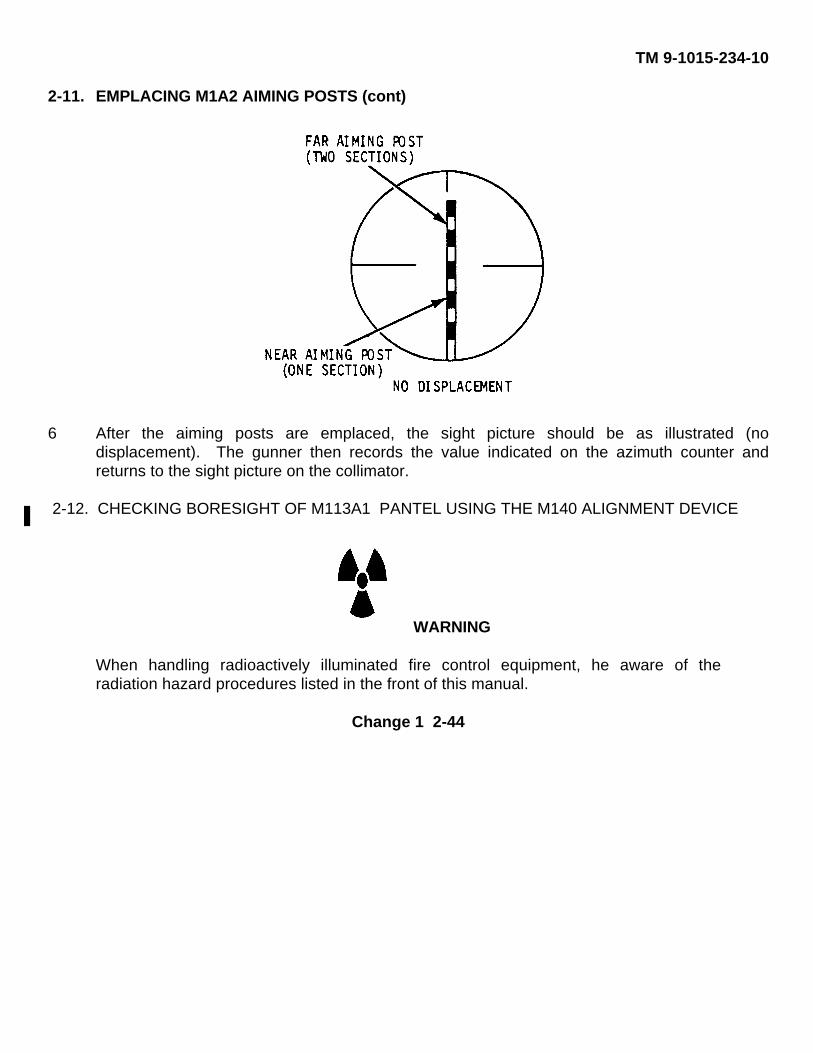
TM 9-1015-234-10
2-11. EMPLACING M1A2 AIMING POSTS (cont)
6 After the aiming posts are emplaced, the sight picture should be as illustrated (nodisplacement). The gunner then records the value indicated on the azimuth counter andreturns to the sight picture on the collimator.
2-12. CHECKING BORESIGHT OF M113A1 PANTEL USING THE M140 ALIGNMENT DEVICE
WARNING
When handling radioactively illuminated fire control equipment, he aware of theradiation hazard procedures listed in the front of this manual.
Change 1 2-44
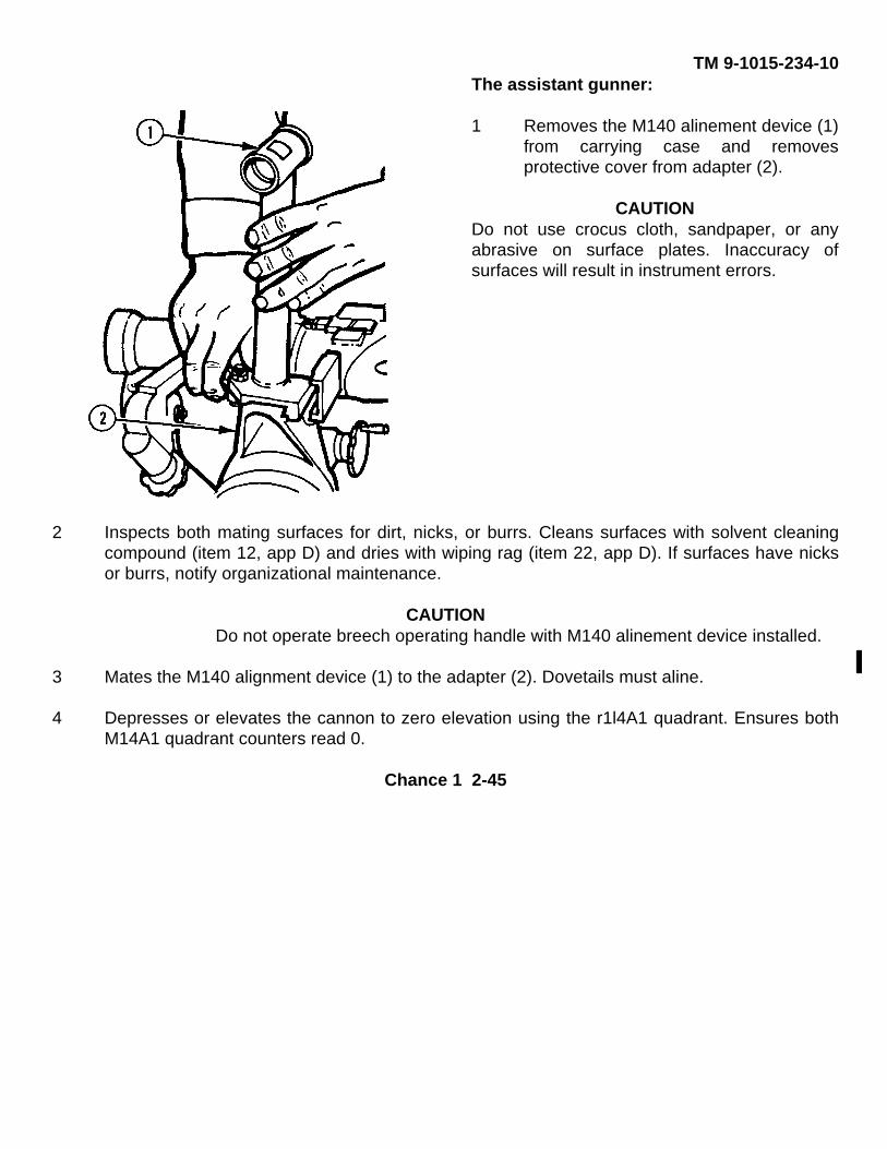
TM 9-1015-234-10The assistant gunner:
1 Removes the M140 alinement device (1)from carrying case and removesprotective cover from adapter (2).
CAUTIONDo not use crocus cloth, sandpaper, or anyabrasive on surface plates. Inaccuracy ofsurfaces will result in instrument errors.
2 Inspects both mating surfaces for dirt, nicks, or burrs. Cleans surfaces with solvent cleaningcompound (item 12, app D) and dries with wiping rag (item 22, app D). If surfaces have nicksor burrs, notify organizational maintenance.
CAUTIONDo not operate breech operating handle with M140 alinement device installed.
3 Mates the M140 alignment device (1) to the adapter (2). Dovetails must aline.
4 Depresses or elevates the cannon to zero elevation using the r1l4A1 quadrant. Ensures bothM14A1 quadrant counters read 0.
Chance 1 2-45
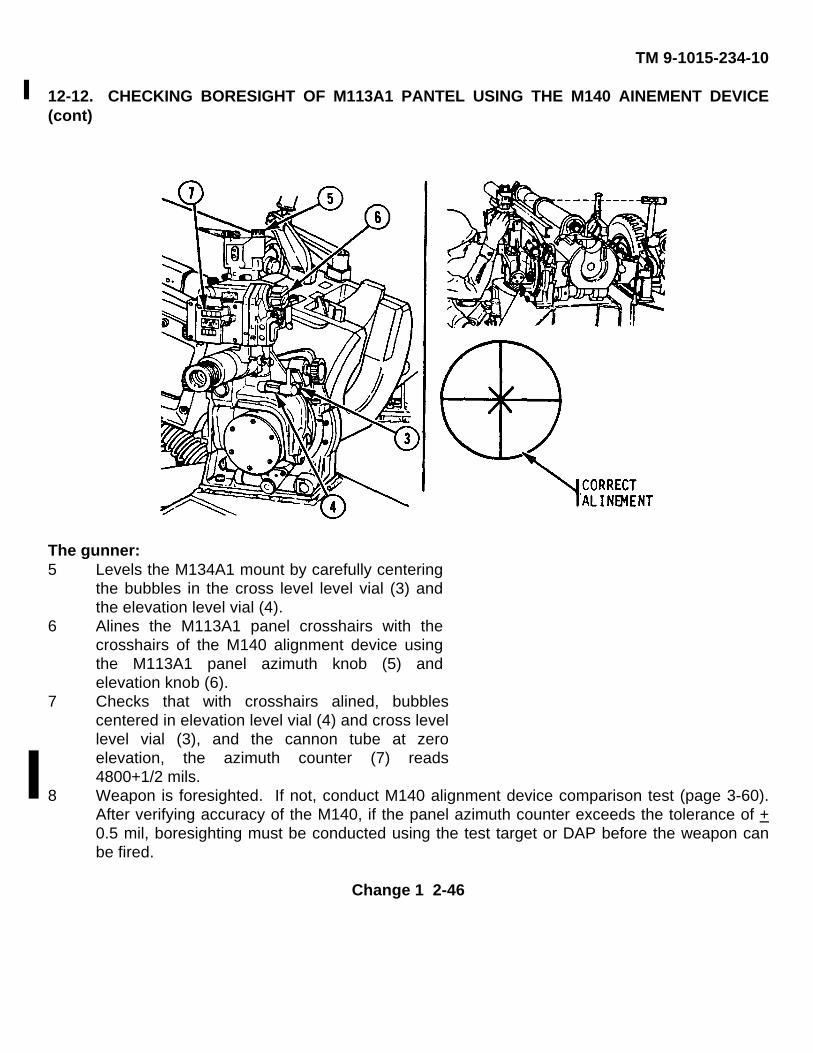
TM 9-1015-234-10
12-12. CHECKING BORESIGHT OF M113A1 PANTEL USING THE M140 AINEMENT DEVICE(cont)
The gunner:5 Levels the M134A1 mount by carefully centering
the bubbles in the cross level level vial (3) andthe elevation level vial (4).
6 Alines the M113A1 panel crosshairs with thecrosshairs of the M140 alignment device usingthe M113A1 panel azimuth knob (5) andelevation knob (6).
7 Checks that with crosshairs alined, bubblescentered in elevation level vial (4) and cross levellevel vial (3), and the cannon tube at zeroelevation, the azimuth counter (7) reads4800+1/2 mils.
8 Weapon is foresighted. If not, conduct M140 alignment device comparison test (page 3-60).After verifying accuracy of the M140, if the panel azimuth counter exceeds the tolerance of +0.5 mil, boresighting must be conducted using the test target or DAP before the weapon canbe fired.
Change 1 2-46
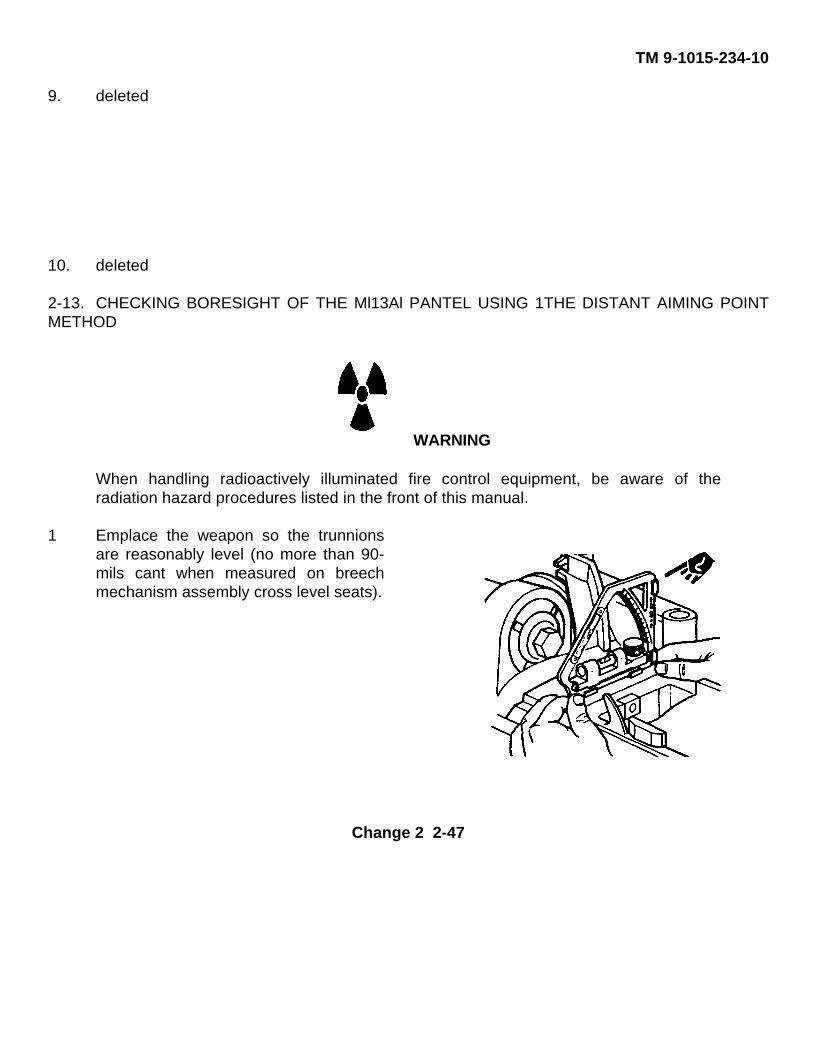
TM 9-1015-234-10
9. deleted
10. deleted
2-13. CHECKING BORESIGHT OF THE Ml13Al PANTEL USING 1THE DISTANT AIMING POINTMETHOD
WARNING
When handling radioactively illuminated fire control equipment, be aware of theradiation hazard procedures listed in the front of this manual.
1 Emplace the weapon so the trunnionsare reasonably level (no more than 90-mils cant when measured on breechmechanism assembly cross level seats).
Change 2 2-47
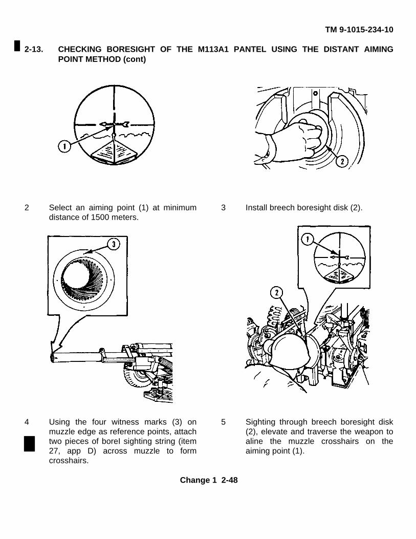
TM 9-1015-234-10
2-13. CHECKING BORESIGHT OF THE M113A1 PANTEL USING THE DISTANT AIMINGPOINT METHOD (cont)
2 Select an aiming point (1) at minimumdistance of 1500 meters.
3 Install breech boresight disk (2).
4 Using the four witness marks (3) onmuzzle edge as reference points, attachtwo pieces of boreI sighting string (item27, app D) across muzzle to formcrosshairs.
5 Sighting through breech boresight disk(2), elevate and traverse the weapon toaline the muzzle crosshairs on theaiming point (1).
Change 1 2-48
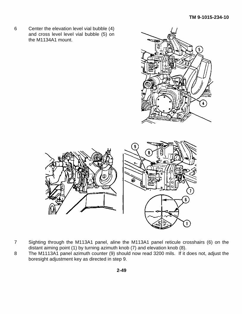
TM 9-1015-234-10
6 Center the elevation level vial bubble (4)and cross level level vial bubble (5) onthe M1134A1 mount.
7 Sighting through the M113A1 panel, aline the M113A1 panel reticule crosshairs (6) on thedistant aiming point (1) by turning azimuth knob (7) and elevation knob (8).
8 The M1113A1 panel azimuth counter (9) should now read 3200 mils. If it does not, adjust theboresight adjustment key as directed in step 9.
2-49
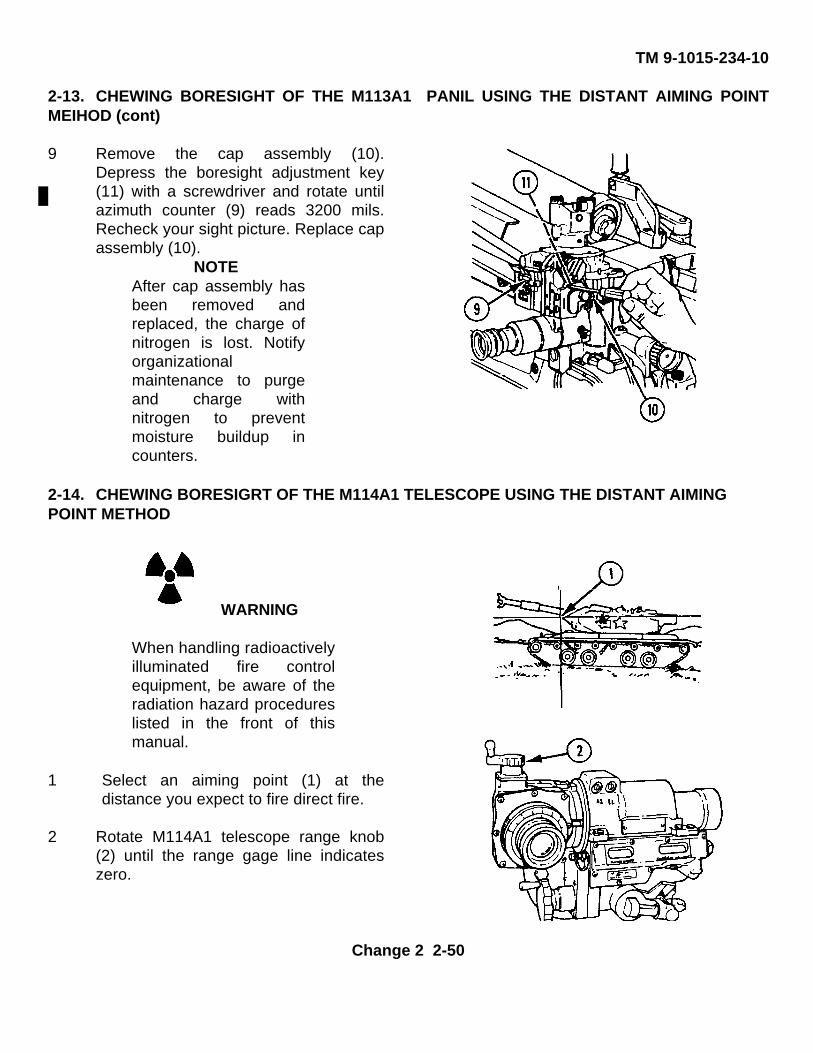
TM 9-1015-234-10
2-13. CHEWING BORESIGHT OF THE M113A1 PANIL USING THE DISTANT AIMING POINTMEIHOD (cont)
9 Remove the cap assembly (10).Depress the boresight adjustment key(11) with a screwdriver and rotate untilazimuth counter (9) reads 3200 mils.Recheck your sight picture. Replace capassembly (10).
NOTEAfter cap assembly hasbeen removed andreplaced, the charge ofnitrogen is lost. Notifyorganizationalmaintenance to purgeand charge withnitrogen to preventmoisture buildup incounters.
2-14. CHEWING BORESIGRT OF THE M114A1 TELESCOPE USING THE DISTANT AIMINGPOINT METHOD
WARNING
When handling radioactivelyilluminated fire controlequipment, be aware of theradiation hazard procedureslisted in the front of thismanual.
1 Select an aiming point (1) at thedistance you expect to fire direct fire.
2 Rotate M114A1 telescope range knob(2) until the range gage line indicateszero.
Change 2 2-50
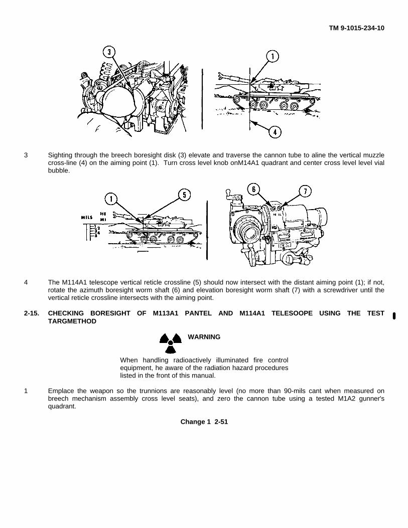
TM 9-1015-234-10
3 Sighting through the breech boresight disk (3) elevate and traverse the cannon tube to aline the vertical muzzlecross-line (4) on the aiming point (1). Turn cross level knob onM14A1 quadrant and center cross level level vialbubble.
4 The M114A1 telescope vertical reticle crossline (5) should now intersect with the distant aiming point (1); if not,rotate the azimuth boresight worm shaft (6) and elevation boresight worm shaft (7) with a screwdriver until thevertical reticle crossline intersects with the aiming point.
2-15. CHECKING BORESIGHT OF M113A1 PANTEL AND M114A1 TELESOOPE USING THE TESTTARGMETHOD
WARNING
When handling radioactively illuminated fire controlequipment, he aware of the radiation hazard procedureslisted in the front of this manual.
1 Emplace the weapon so the trunnions are reasonably level (no more than 90-mils cant when measured onbreech mechanism assembly cross level seats), and zero the cannon tube using a tested M1A2 gunner'squadrant.
Change 1 2-51
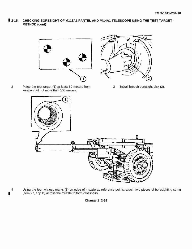
TM 9-1015-234-10
2-15. CHECKING BORESIGHT OF M113A1 PANTEL AND Ml14A1 TELESOOPE USING THE TEST TARGETMETHOD (cont)
2 Place the test target (1) at least 50 meters fromweapon but not more than 100 meters.
3 Install breech boresight disk (2).
4 Using the four witness marks (3) on edge of muzzle as reference points, attach two pieces of boresighting string(item 27, app D) across the muzzle to form crosshairs.
Change 1 2-52
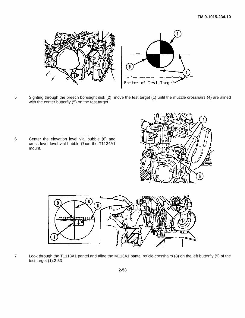
TM 9-1015-234-10
5 Sighting through the breech boresight disk (2) move the test target (1) until the muzzle crosshairs (4) are alinedwith the center butterfly (5) on the test target.
6 Center the elevation level vial bubble (6) andcross level level vial bubble (7)on the T1134A1mount.
7 Look through the T1113A1 pantel and aline the M113A1 pantel reticle crosshairs (8) on the left butterfly (9) of thetest target (1).2-53
2-53
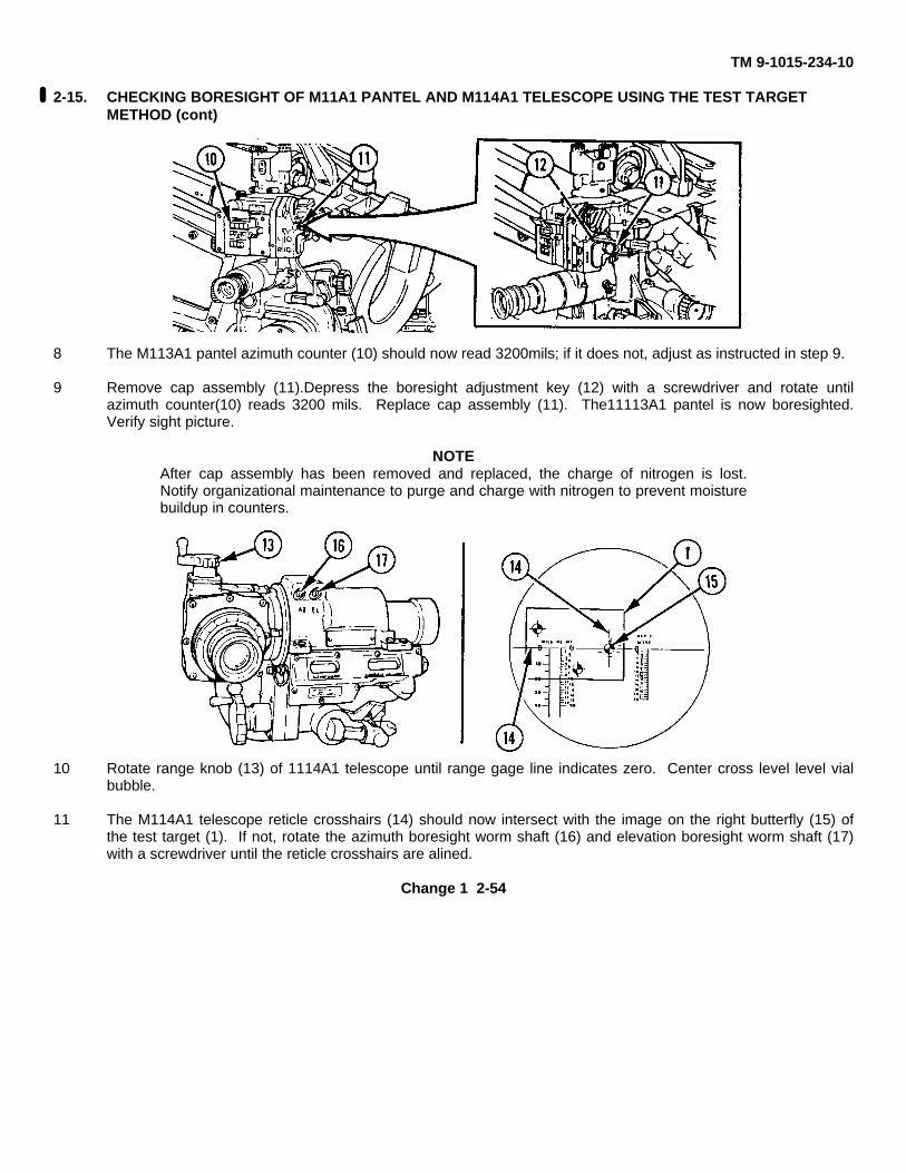
TM 9-1015-234-10
2-15. CHECKING BORESIGHT OF M11A1 PANTEL AND M114A1 TELESCOPE USING THE TEST TARGETMETHOD (cont)
8 The M113A1 pantel azimuth counter (10) should now read 3200mils; if it does not, adjust as instructed in step 9.
9 Remove cap assembly (11).Depress the boresight adjustment key (12) with a screwdriver and rotate untilazimuth counter(10) reads 3200 mils. Replace cap assembly (11). The11113A1 pantel is now boresighted.Verify sight picture.
NOTEAfter cap assembly has been removed and replaced, the charge of nitrogen is lost.Notify organizational maintenance to purge and charge with nitrogen to prevent moisturebuildup in counters.
10 Rotate range knob (13) of 1114A1 telescope until range gage line indicates zero. Center cross level level vialbubble.
11 The M114A1 telescope reticle crosshairs (14) should now intersect with the image on the right butterfly (15) ofthe test target (1). If not, rotate the azimuth boresight worm shaft (16) and elevation boresight worm shaft (17)with a screwdriver until the reticle crosshairs are alined.
Change 1 2-54
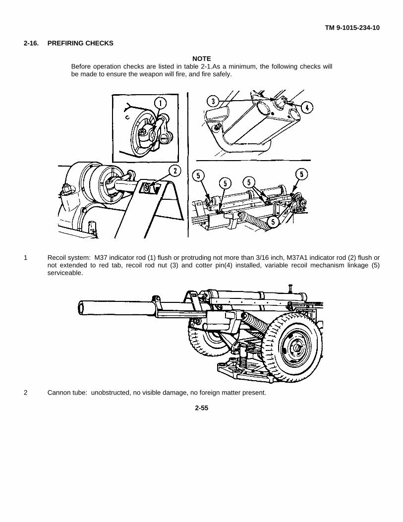
TM 9-1015-234-10
2-16. PREFIRING CHECKS
NOTEBefore operation checks are listed in table 2-1.As a minimum, the following checks willbe made to ensure the weapon will fire, and fire safely.
1 Recoil system: M37 indicator rod (1) flush or protruding not more than 3/16 inch, M37A1 indicator rod (2) flush ornot extended to red tab, recoil rod nut (3) and cotter pin(4) installed, variable recoil mechanism linkage (5)serviceable.
2 Cannon tube: unobstructed, no visible damage, no foreign matter present.
2-55
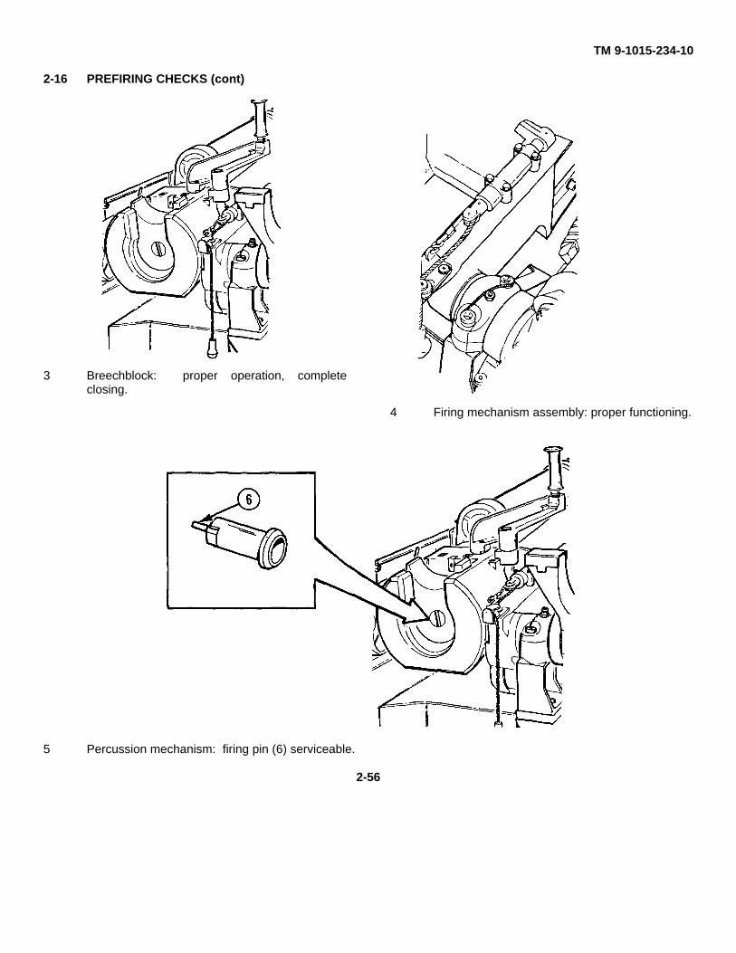
TM 9-1015-234-10
2-16 PREFIRING CHECKS (cont)
3 Breechblock: proper operation, completeclosing.
4 Firing mechanism assembly: proper functioning.
5 Percussion mechanism: firing pin (6) serviceable.
2-56
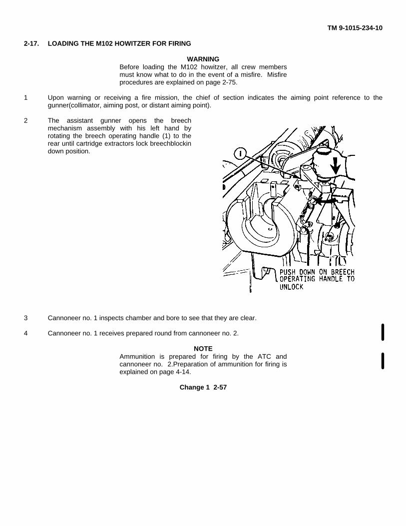
TM 9-1015-234-10
2-17. LOADING THE M102 HOWITZER FOR FIRING
WARNINGBefore loading the M102 howitzer, all crew membersmust know what to do in the event of a misfire. Misfireprocedures are explained on page 2-75.
1 Upon warning or receiving a fire mission, the chief of section indicates the aiming point reference to thegunner(collimator, aiming post, or distant aiming point).
2 The assistant gunner opens the breechmechanism assembly with his left hand byrotating the breech operating handle (1) to therear until cartridge extractors lock breechblockindown position.
3 Cannoneer no. 1 inspects chamber and bore to see that they are clear.
4 Cannoneer no. 1 receives prepared round from cannoneer no. 2.
NOTEAmmunition is prepared for firing by the ATC andcannoneer no. 2.Preparation of ammunition for firing isexplained on page 4-14.
Change 1 2-57
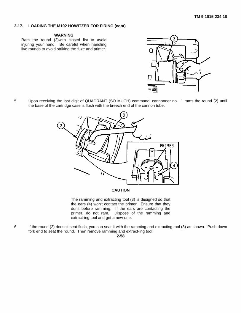
TM 9-1015-234-10
2-17. LOADING THE M102 HOWITZER FOR FIRING (cont)
WARNINGRam the round (2)with closed fist to avoidinjuring your hand. Be careful when handlinglive rounds to avoid striking the fuze and primer.
5 Upon receiving the last digit of QUADRANT (SO MUCH) command, cannoneer no. 1 rams the round (2) untilthe base of the cartridge case is flush with the breech end of the cannon tube.
CAUTION
The ramming and extracting tool (3) is designed so thatthe ears (4) won't contact the primer. Ensure that theydon't before ramming. If the ears are contacting theprimer, do not ram. Dispose of the ramming andextract-ing tool and get a new one.
6 If the round (2) doesn't seat flush, you can seat it with the ramming and extracting tool (3) as shown. Push downfork end to seat the round. Then remove ramming and extract-ing tool.
2-58
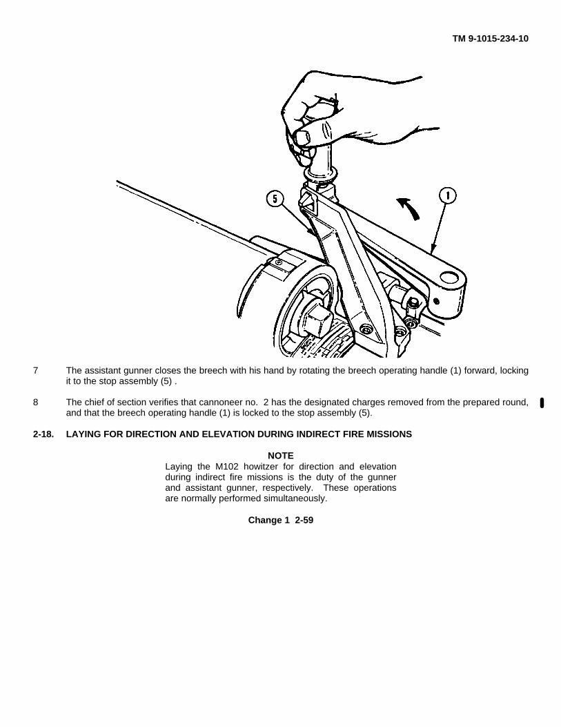
TM 9-1015-234-10
7 The assistant gunner closes the breech with his hand by rotating the breech operating handle (1) forward, lockingit to the stop assembly (5) .
8 The chief of section verifies that cannoneer no. 2 has the designated charges removed from the prepared round,and that the breech operating handle (1) is locked to the stop assembly (5).
2-18. LAYING FOR DIRECTION AND ELEVATION DURING INDIRECT FIRE MISSIONS
NOTELaying the M102 howitzer for direction and elevationduring indirect fire missions is the duty of the gunnerand assistant gunner, respectively. These operationsare normally performed simultaneously.
Change 1 2-59
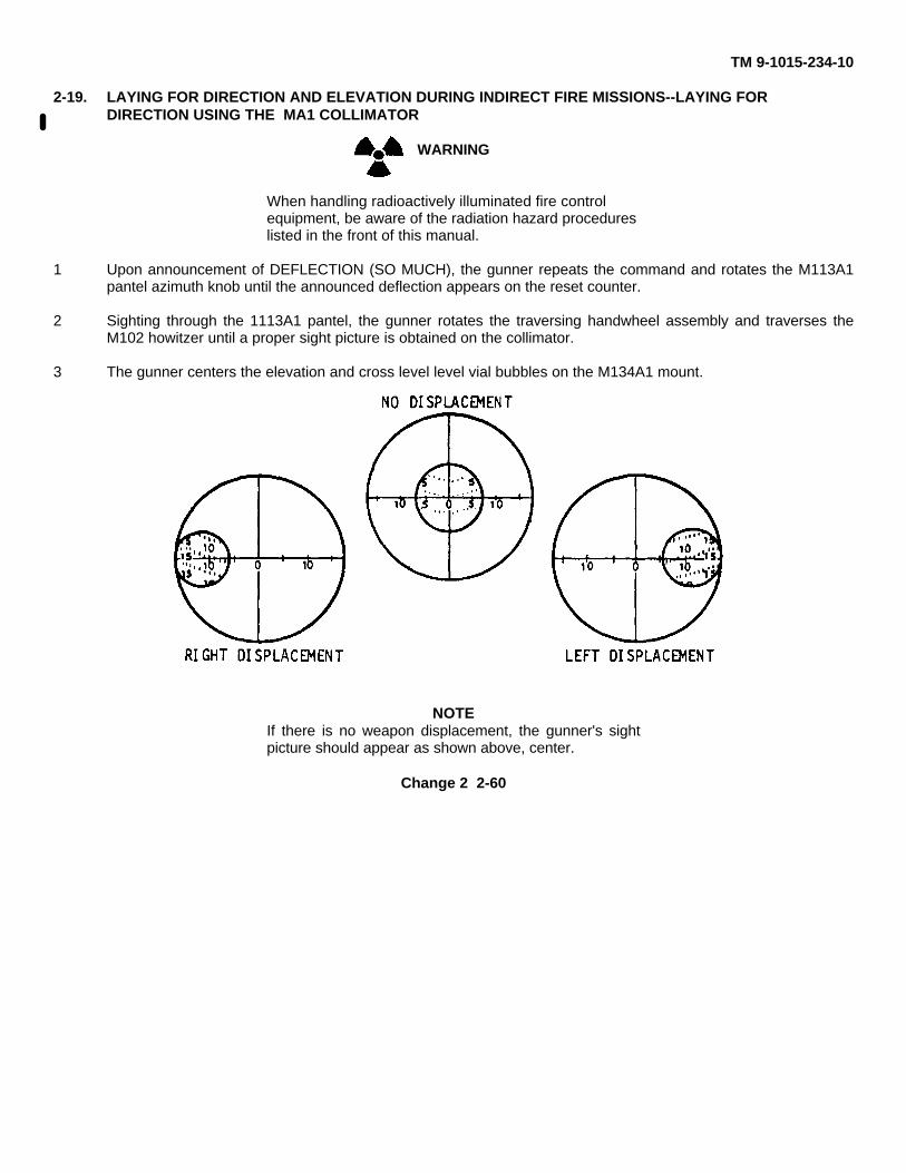
TM 9-1015-234-10
2-19. LAYING FOR DIRECTION AND ELEVATION DURING INDIRECT FIRE MISSIONS--LAYING FORDIRECTION USING THE MA1 COLLIMATOR
WARNING
When handling radioactively illuminated fire controlequipment, be aware of the radiation hazard procedureslisted in the front of this manual.
1 Upon announcement of DEFLECTION (SO MUCH), the gunner repeats the command and rotates the M113A1pantel azimuth knob until the announced deflection appears on the reset counter.
2 Sighting through the 1113A1 pantel, the gunner rotates the traversing handwheel assembly and traverses theM102 howitzer until a proper sight picture is obtained on the collimator.
3 The gunner centers the elevation and cross level level vial bubbles on the M134A1 mount.
NOTEIf there is no weapon displacement, the gunner's sightpicture should appear as shown above, center.
Change 2 2-60
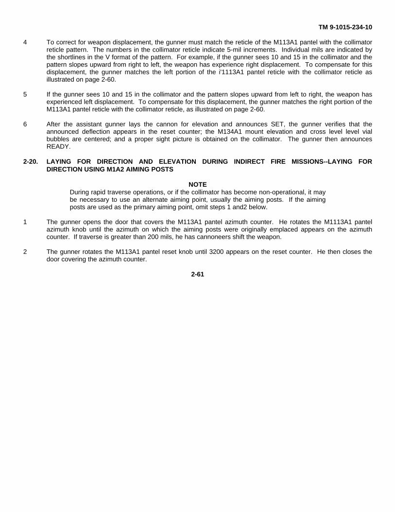
TM 9-1015-234-10
4 To correct for weapon displacement, the gunner must match the reticle of the M113A1 pantel with the collimatorreticle pattern. The numbers in the collimator reticle indicate 5-mil increments. Individual mils are indicated bythe shortlines in the V format of the pattern. For example, if the gunner sees 10 and 15 in the collimator and thepattern slopes upward from right to left, the weapon has experience right displacement. To compensate for thisdisplacement, the gunner matches the left portion of the i'1113A1 pantel reticle with the collimator reticle asillustrated on page 2-60.
5 If the gunner sees 10 and 15 in the collimator and the pattern slopes upward from left to right, the weapon hasexperienced left displacement. To compensate for this displacement, the gunner matches the right portion of theM113A1 pantel reticle with the collimator reticle, as illustrated on page 2-60.
6 After the assistant gunner lays the cannon for elevation and announces SET, the gunner verifies that theannounced deflection appears in the reset counter; the M134A1 mount elevation and cross level level vialbubbles are centered; and a proper sight picture is obtained on the collimator. The gunner then announcesREADY.
2-20. LAYING FOR DIRECTION AND ELEVATION DURING INDIRECT FIRE MISSIONS--LAYING FORDIRECTION USING M1A2 AIMING POSTS
NOTEDuring rapid traverse operations, or if the collimator has become non-operational, it maybe necessary to use an alternate aiming point, usually the aiming posts. If the aimingposts are used as the primary aiming point, omit steps 1 and2 below.
1 The gunner opens the door that covers the M113A1 pantel azimuth counter. He rotates the M1113A1 pantelazimuth knob until the azimuth on which the aiming posts were originally emplaced appears on the azimuthcounter. If traverse is greater than 200 mils, he has cannoneers shift the weapon.
2 The gunner rotates the M113A1 pantel reset knob until 3200 appears on the reset counter. He then closes thedoor covering the azimuth counter.
2-61
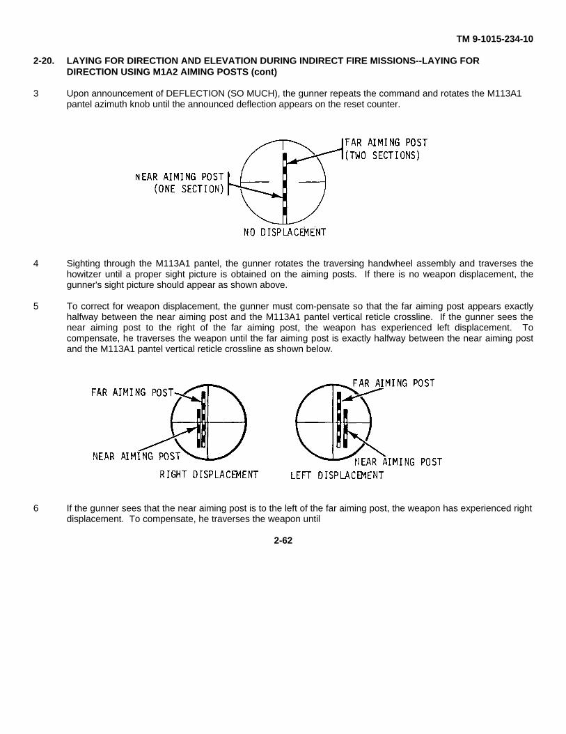
TM 9-1015-234-10
2-20. LAYING FOR DIRECTION AND ELEVATION DURING INDIRECT FIRE MISSIONS--LAYING FORDIRECTION USING M1A2 AIMING POSTS (cont)
3 Upon announcement of DEFLECTION (SO MUCH), the gunner repeats the command and rotates the M113A1pantel azimuth knob until the announced deflection appears on the reset counter.
4 Sighting through the M113A1 pantel, the gunner rotates the traversing handwheel assembly and traverses thehowitzer until a proper sight picture is obtained on the aiming posts. If there is no weapon displacement, thegunner's sight picture should appear as shown above.
5 To correct for weapon displacement, the gunner must com-pensate so that the far aiming post appears exactlyhalfway between the near aiming post and the M113A1 pantel vertical reticle crossline. If the gunner sees thenear aiming post to the right of the far aiming post, the weapon has experienced left displacement. Tocompensate, he traverses the weapon until the far aiming post is exactly halfway between the near aiming postand the M113A1 pantel vertical reticle crossline as shown below.
6 If the gunner sees that the near aiming post is to the left of the far aiming post, the weapon has experienced rightdisplacement. To compensate, he traverses the weapon until
2-62
TM 9-1015-234-10
the far aiming post is exactly halfway between the near aiming post and the M113A1 pantel vertical reticlecrossline as shown in the bottom illustration on page 2-62.
7 After the assistant gunner lays the cannon for elevation and announces SET, the gunner verifies that theannounced deflection appears on the M113A1 pantel reset counter, theM134A1 mount elevation and cross levellevel vial bubbles are centered, and that a proper sight picture is obtained on the aiming posts. He announcesREADY.
2-21. LAYING FOR DIRECTION AND ELEVATION DURING INDIRECT FIRE MISSIONS--LAYING FORELEVATION
1 Upon announcement of QUADRANT (SO MUCH), the assistant gunner repeats the command and rotates theM14A1 quadrant elevation knob until the announced quadrant appears on the elevation counter.
NOTEEach time the howitzer is traversed or the cannon elevated or depressed, the assistantgunner must repeat steps 2 and 3 until cannon is set.
2 Operating the elevating handwheel assembly, the assistant gunner elevates or depresses the cannon until theM14A1 quadrant elevation level vial bubble centers.
3 The assistant gunner centers the cross level level vial bubble on the M14A1 quadrant.
4 After the gunner has traversed the howitzer, the assistant gunner verifies that the cross level and elevation levelvial bubbles are centered and the announced quadrant appears on the t114A1 quadrant elevation counter. Hethen announces SET.
2-22. LAYING FOR DIRECTION AND ELEVATION DURING DIRECT FIRE MISSIONS
WARNING
When handling radioactively illuminated fire controlequipment, he aware of the radiation hazard procedureslisted in the front of this manual.
WARNINGDirect fire on targets located closer than 600meters fromthe howitzer will only be fired upon during combatsituations. Lethal fragments can travel up to 400 metersfrom point-of-burst.
Change 1 2-63
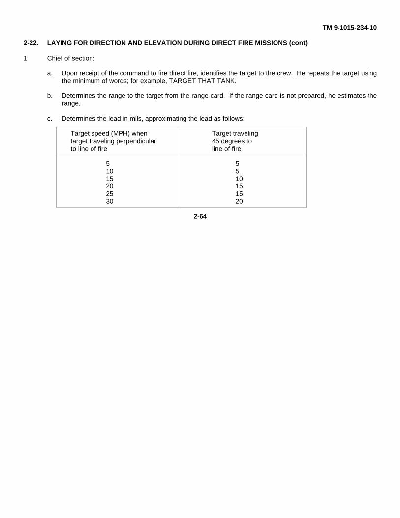
TM 9-1015-234-10
2-22. LAYING FOR DIRECTION AND ELEVATION DURING DIRECT FIRE MISSIONS (cont)
1 Chief of section:
a. Upon receipt of the command to fire direct fire, identifies the target to the crew. He repeats the target usingthe minimum of words; for example, TARGET THAT TANK.
b. Determines the range to the target from the range card. If the range card is not prepared, he estimates therange.
c. Determines the lead in mils, approximating the lead as follows:
Target speed (MPH) when Target travelingtarget traveling perpendicular 45 degrees toto line of fire line of fire
5 510 515 1020 1525 1530 20
2-64
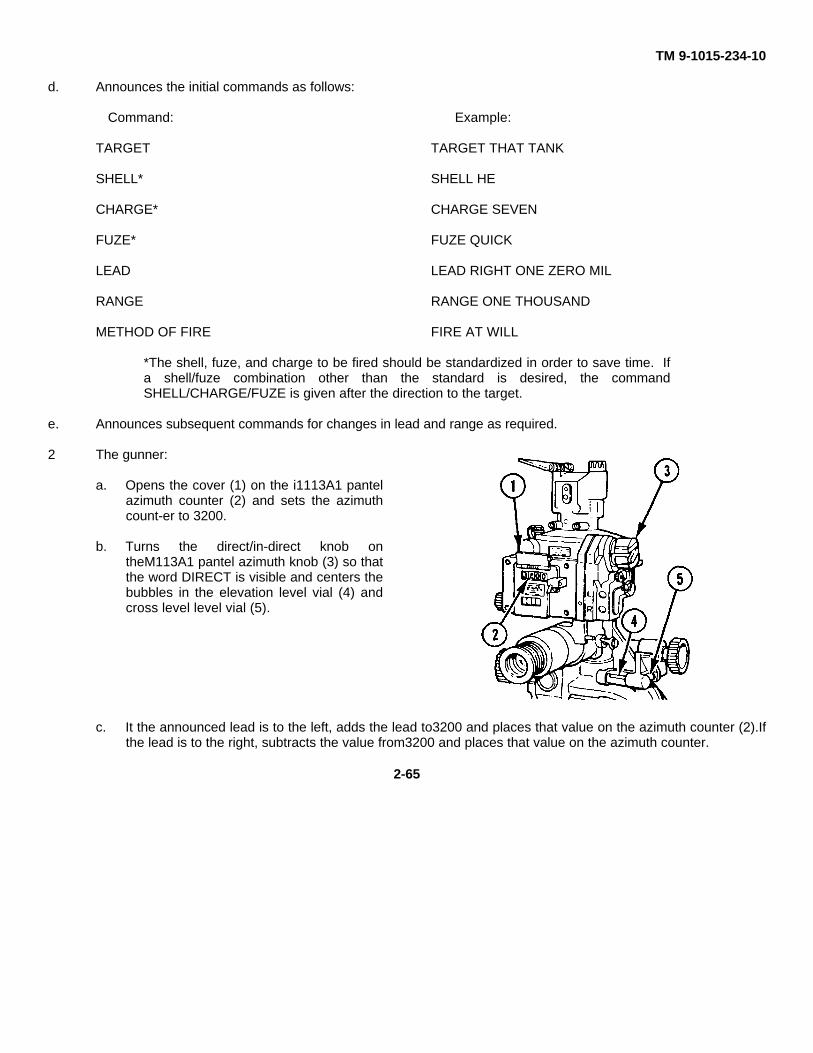
TM 9-1015-234-10
d. Announces the initial commands as follows:
Command: Example:
TARGET TARGET THAT TANK
SHELL* SHELL HE
CHARGE* CHARGE SEVEN
FUZE* FUZE QUICK
LEAD LEAD RIGHT ONE ZERO MIL
RANGE RANGE ONE THOUSAND
METHOD OF FIRE FIRE AT WILL
*The shell, fuze, and charge to be fired should be standardized in order to save time. Ifa shell/fuze combination other than the standard is desired, the commandSHELL/CHARGE/FUZE is given after the direction to the target.
e. Announces subsequent commands for changes in lead and range as required.
2 The gunner:
a. Opens the cover (1) on the i1113A1 pantelazimuth counter (2) and sets the azimuthcount-er to 3200.
b. Turns the direct/in-direct knob ontheM113A1 pantel azimuth knob (3) so thatthe word DIRECT is visible and centers thebubbles in the elevation level vial (4) andcross level level vial (5).
c. It the announced lead is to the left, adds the lead to3200 and places that value on the azimuth counter (2).Ifthe lead is to the right, subtracts the value from3200 and places that value on the azimuth counter.
2-65
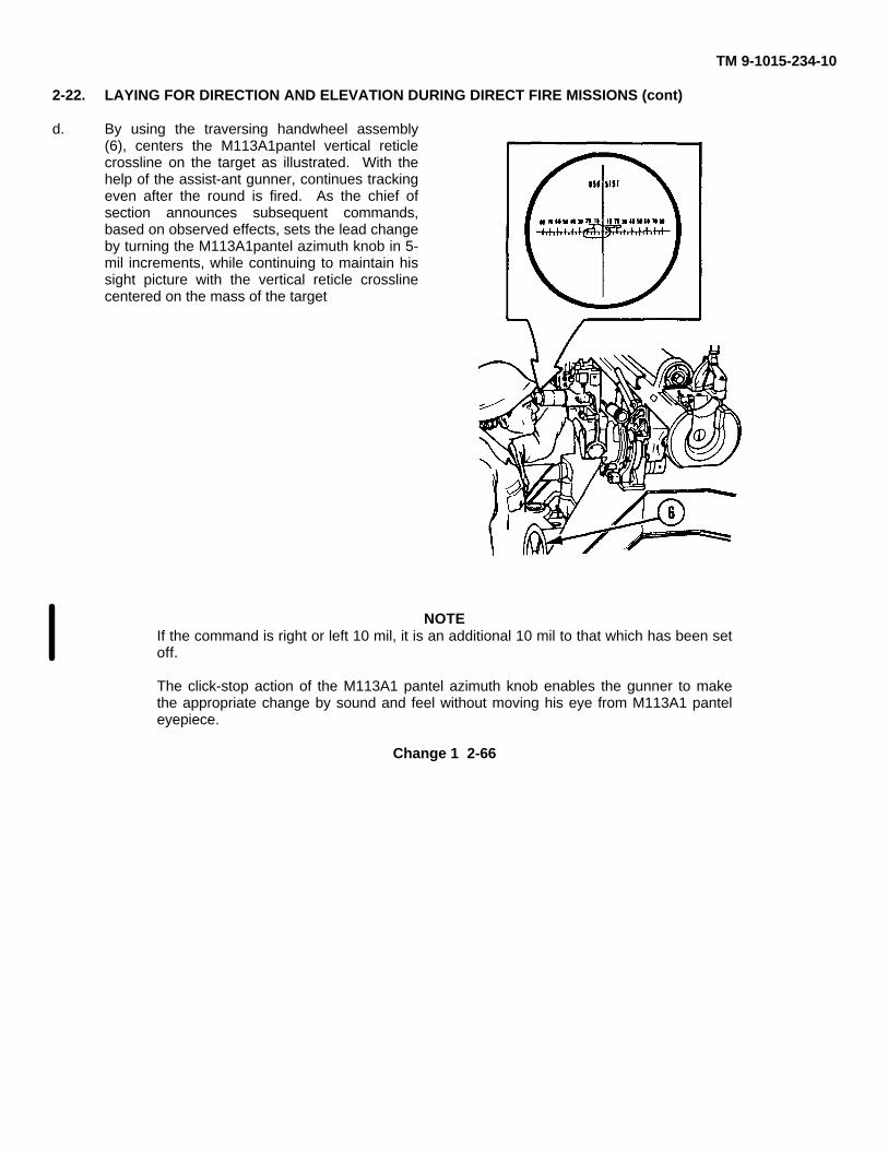
TM 9-1015-234-10
2-22. LAYING FOR DIRECTION AND ELEVATION DURING DIRECT FIRE MISSIONS (cont)
d. By using the traversing handwheel assembly(6), centers the M113A1pantel vertical reticlecrossline on the target as illustrated. With thehelp of the assist-ant gunner, continues trackingeven after the round is fired. As the chief ofsection announces subsequent commands,based on observed effects, sets the lead changeby turning the M113A1pantel azimuth knob in 5-mil increments, while continuing to maintain hissight picture with the vertical reticle crosslinecentered on the mass of the target
NOTEIf the command is right or left 10 mil, it is an additional 10 mil to that which has been setoff.
The click-stop action of the M113A1 pantel azimuth knob enables the gunner to makethe appropriate change by sound and feel without moving his eye from M113A1 panteleyepiece.
Change 1 2-66
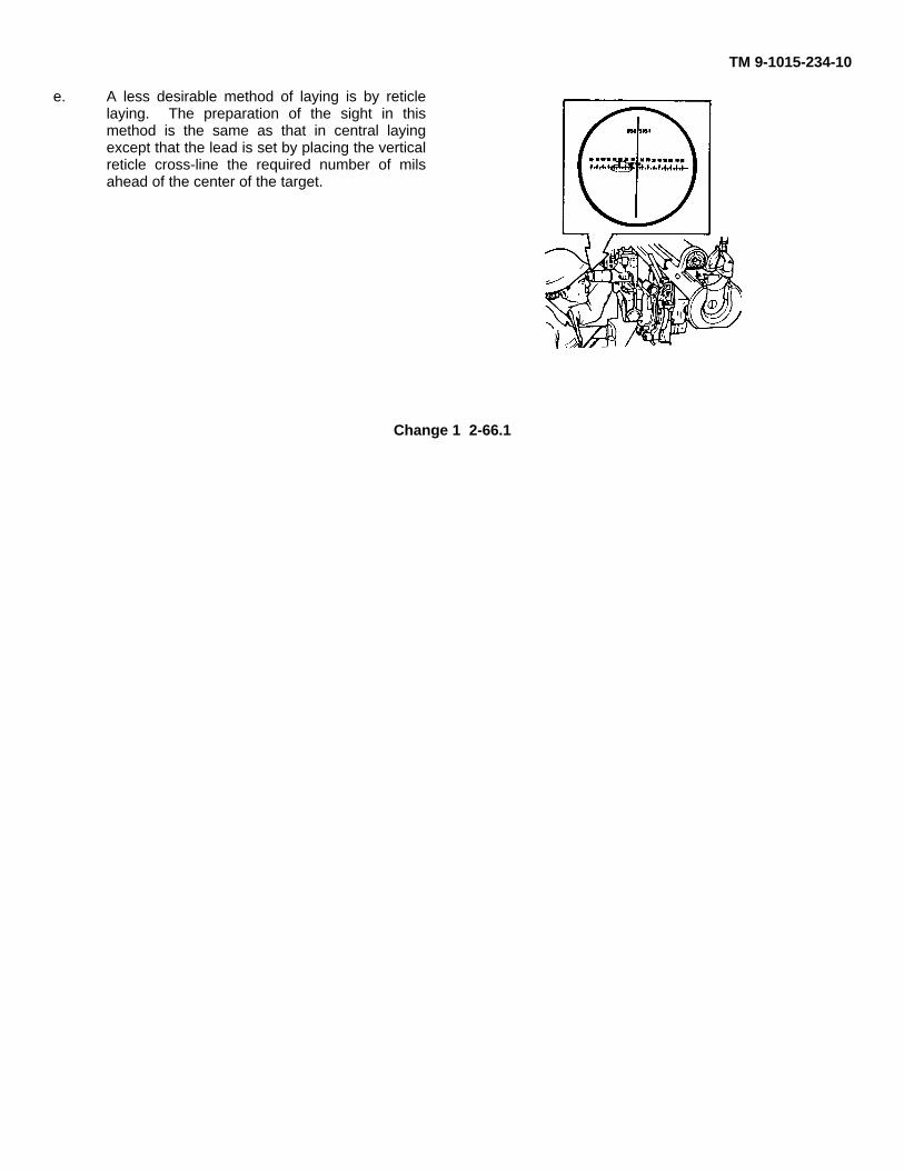
TM 9-1015-234-10
e. A less desirable method of laying is by reticlelaying. The preparation of the sight in thismethod is the same as that in central layingexcept that the lead is set by placing the verticalreticle cross-line the required number of milsahead of the center of the target.
Change 1 2-66.1
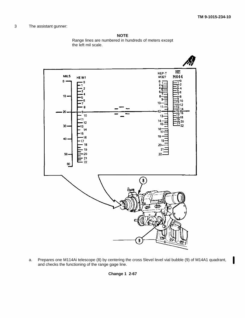
TM 9-1015-234-10
3 The assistant gunner:
NOTERange lines are numbered in hundreds of meters exceptthe left mil scale.
a. Prepares one M114Ai telescope (8) by centering the cross 5level level vial bubble (9) of M14A1 quadrant,and checks the functioning of the range gage line.
Change 1 2-67
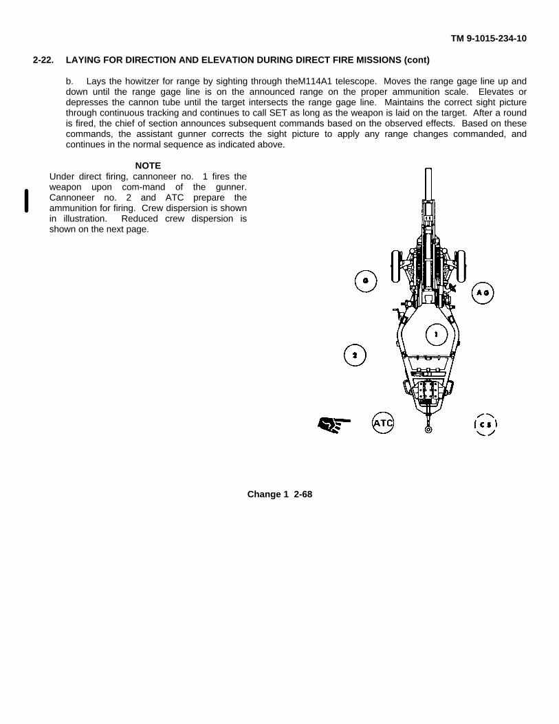
TM 9-1015-234-10
2-22. LAYING FOR DIRECTION AND ELEVATION DURING DIRECT FIRE MISSIONS (cont)
b. Lays the howitzer for range by sighting through theM114A1 telescope. Moves the range gage line up anddown until the range gage line is on the announced range on the proper ammunition scale. Elevates ordepresses the cannon tube until the target intersects the range gage line. Maintains the correct sight picturethrough continuous tracking and continues to call SET as long as the weapon is laid on the target. After a roundis fired, the chief of section announces subsequent commands based on the observed effects. Based on thesecommands, the assistant gunner corrects the sight picture to apply any range changes commanded, andcontinues in the normal sequence as indicated above.
NOTEUnder direct firing, cannoneer no. 1 fires theweapon upon com-mand of the gunner.Cannoneer no. 2 and ATC prepare theammunition for firing. Crew dispersion is shownin illustration. Reduced crew dispersion isshown on the next page.
Change 1 2-68
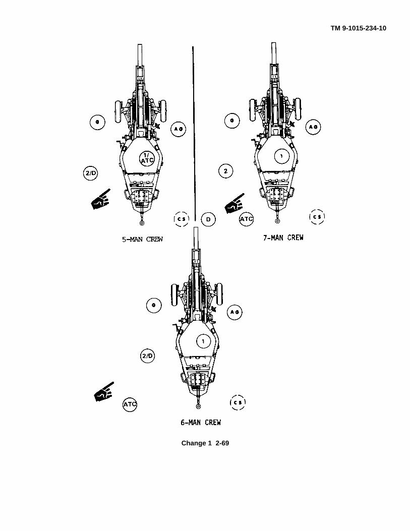
TM 9-1015-234-10
Change 1 2-69
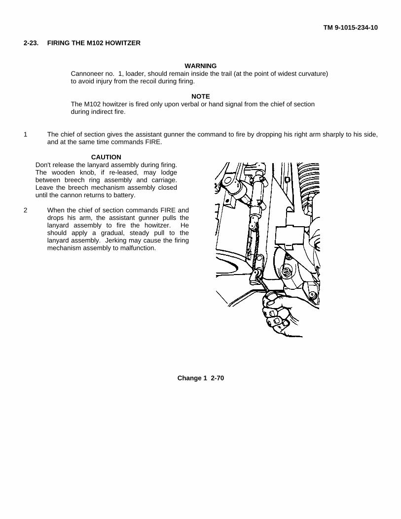
TM 9-1015-234-10
2-23. FIRING THE M102 HOWITZER
WARNINGCannoneer no. 1, loader, should remain inside the trail (at the point of widest curvature)to avoid injury from the recoil during firing.
NOTEThe M102 howitzer is fired only upon verbal or hand signal from the chief of sectionduring indirect fire.
1 The chief of section gives the assistant gunner the command to fire by dropping his right arm sharply to his side,and at the same time commands FIRE.
CAUTIONDon't release the lanyard assembly during firing.The wooden knob, if re-leased, may lodgebetween breech ring assembly and carriage.Leave the breech mechanism assembly closeduntil the cannon returns to battery.
2 When the chief of section commands FIRE anddrops his arm, the assistant gunner pulls thelanyard assembly to fire the howitzer. Heshould apply a gradual, steady pull to thelanyard assembly. Jerking may cause the firingmechanism assembly to malfunction.
Change 1 2-70
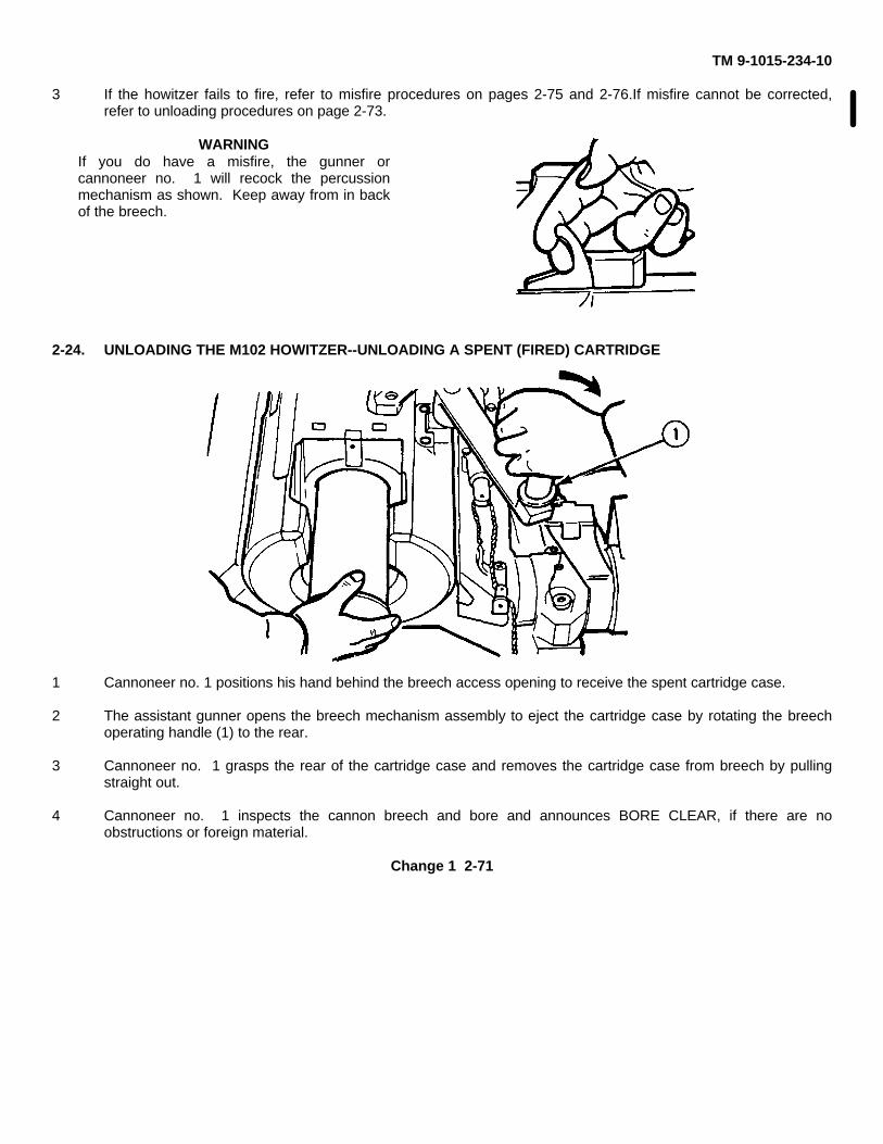
TM 9-1015-234-10
3 If the howitzer fails to fire, refer to misfire procedures on pages 2-75 and 2-76.If misfire cannot be corrected,refer to unloading procedures on page 2-73.
WARNINGIf you do have a misfire, the gunner orcannoneer no. 1 will recock the percussionmechanism as shown. Keep away from in backof the breech.
2-24. UNLOADING THE M102 HOWITZER--UNLOADING A SPENT (FIRED) CARTRIDGE
1 Cannoneer no. 1 positions his hand behind the breech access opening to receive the spent cartridge case.
2 The assistant gunner opens the breech mechanism assembly to eject the cartridge case by rotating the breechoperating handle (1) to the rear.
3 Cannoneer no. 1 grasps the rear of the cartridge case and removes the cartridge case from breech by pullingstraight out.
4 Cannoneer no. 1 inspects the cannon breech and bore and announces BORE CLEAR, if there are noobstructions or foreign material.
Change 1 2-71
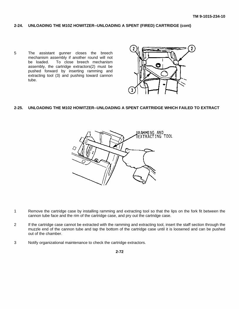
TM 9-1015-234-10
2-24. UNLOADING THE M10Z HOWITZER--UNLOADING A SPENT (FIRED) CARTRIDGE (cont)
5 The assistant gunner closes the breechmechanism assembly if another round will notbe loaded. To close breech mechanismassembly, the cartridge extractors(2) must bepushed forward by inserting ramming andextracting tool (3) and pushing toward cannontube.
2-25. UNLOADING THE M102 HOWITZER--UNLOADING A SPENT CARTRIDGE WHICH FAILED TO EXTRACT
1 Remove the cartridge case by installing ramming and extracting tool so that the lips on the fork fit between thecannon tube face and the rim of the cartridge case, and pry out the cartridge case.
2 If the cartridge case cannot be extracted with the ramming and extracting tool, insert the staff section through themuzzle end of the cannon tube and tap the bottom of the cartridge case until it is loosened and can be pushedout of the chamber.
3 Notify organizational maintenance to check the cartridge extractors.
2-72
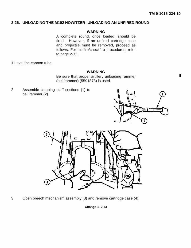
TM 9-1015-234-10
2-26. UNLOADING THE M102 HOWITZER--UNLOADING AN UNFIRED ROUND
WARNINGA complete round, once loaded, should befired. However, if an unfired cartridge caseand projectile must be removed, proceed asfollows. For misfire/checkfire procedures, referto page 2-75.
1 Level the cannon tube.
WARNINGBe sure that proper artillery unloading rammer(bell rammer) (5591873) is used.
2 Assemble cleaning staff sections (1) tobell rammer (2).
3 Open breech mechanism assembly (3) and remove cartridge case (4).
Change 1 2-73
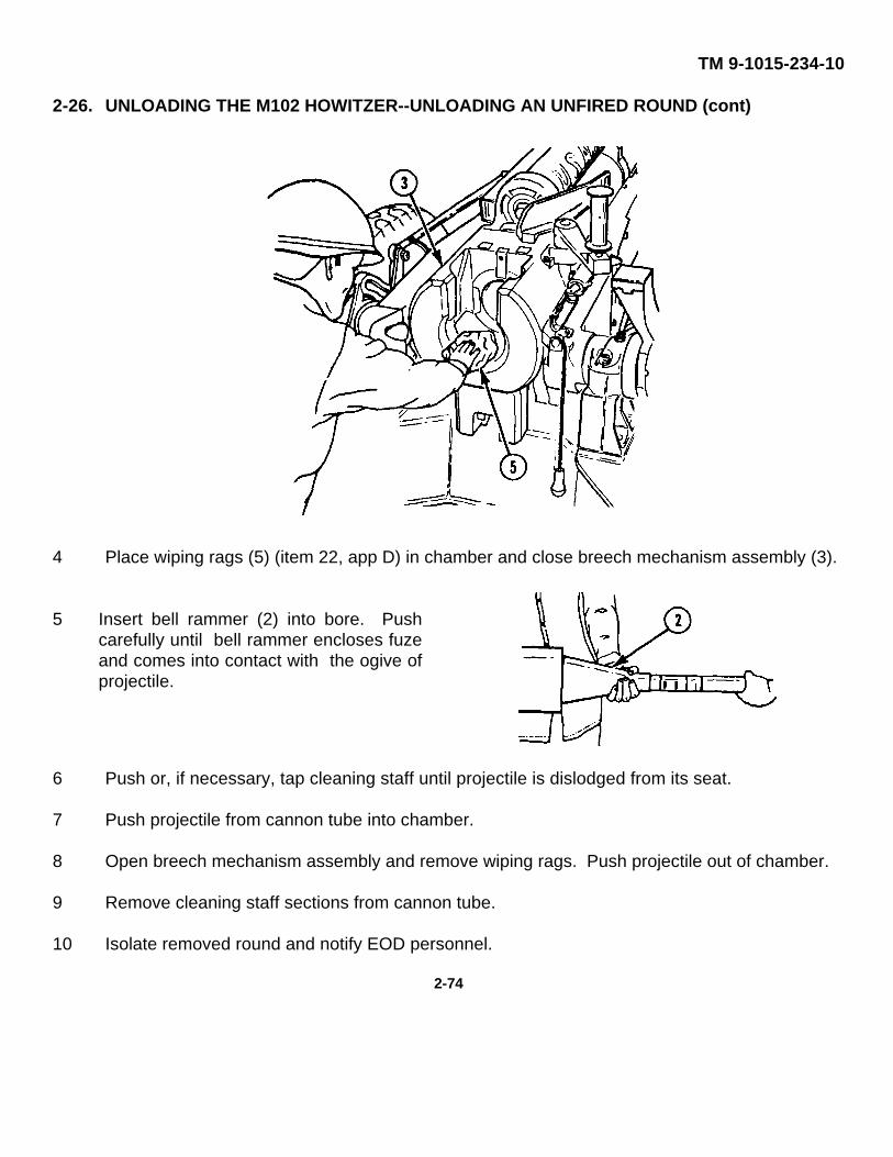
TM 9-1015-234-10
2-26. UNLOADING THE M102 HOWITZER--UNLOADING AN UNFIRED ROUND (cont)
4 Place wiping rags (5) (item 22, app D) in chamber and close breech mechanism assembly (3).
5 Insert bell rammer (2) into bore. Pushcarefully until bell rammer encloses fuzeand comes into contact with the ogive ofprojectile.
6 Push or, if necessary, tap cleaning staff until projectile is dislodged from its seat.
7 Push projectile from cannon tube into chamber.
8 Open breech mechanism assembly and remove wiping rags. Push projectile out of chamber.
9 Remove cleaning staff sections from cannon tube.
10 Isolate removed round and notify EOD personnel.
2-74
TM 9-1015-234-10
2-27. MISFIRE/CHECKFIRE PROCEDURES
a. General precautions.
Conditions described below are rarely encountered with a properly maintained weapon and whenauthorized and properly maintained ammunition is fired. To avoid injury to personnel and equipmentdamage, however, it is important to understand the nature of these conditions and to be familiar withpreventive and corrective procedures.
b. Definitions.
(1) MISFIRE. A misfire is a failure of a round to fire after initiating action is taken. Thefailure may be due to a faulty firing (percussion) mechanism or a faulty element in the propellingcharge explosive train. A misfire in itself is not dangerous; however, it cannot be distinguishedimmediately from a delay in functioning of the weapon's firing mechanism assembly or from ahangfire. Therefore, misfires must be treated as delayed firings until determined otherwise.
(2) HANGFIRE. A hangfire is a delay in the functioning of a propelling charge explosivetrain at the time of firing. The delay, though unpredictable, ranges from a fraction of a second toseveral minutes. A hangfire cannot be distinguished immediately from a misfire.
(3) STICKER. A sticker is a projectile that is lodged in the cannon tube after being fired.Stickers result from insufficient chamber pressure.
(4) HOT WEAPON. A hot weapon is one in which the cannon tube and breech havebeen brought to a sufficiently high temperature by previous firings that they can transmit, in severalminutes, enough heat to the round to activate its explosive components. A weapon should beconsidered hot if it has violated the prescribed rates of fire.
(5) COOK-OFF. The functioning of the propelling charge or projectile when initiated bythe heat of the weapon.
(6) CHECKFIRE. CHECKFIRE is a command which normally is given by the batteryexecutive officer, but in an emergency may be given by anyone present.
2-75
TM 9-1015-234-10
2-28. MISFIRE/CHECKFIRE PREVENTIVE OR CORRECTIVE PROCEDURES
1 At the command, CHECKFIRE, regardless of its source, cease firing immediately and unloadas directed.
NOTEFigure 2-1 shows a summary of procedures for correcting a misfire if thecannon tube is cold. Figure 2-2 summarizes corrective procedures if thecannon tube is hot.
2 If the cannon tube is cold, make two more attempts to fire. Although time is not as critical aswhen the cannon tube is hot, it is military policy to either fire or unload chambered roundswithin 5 minutes, if possible.
WARNINGThe breech should not be opened for at least 2 minutes after the firingattempt. All personnel not required for unloading should seek protectivecover at least 50 meters from the weapon to avoid injury if weapon firesunexpectedly. Keep weapon trained on target and stand clear of muzzleand path of recoil until round is unloaded.
When firing is interrupted, remove projectile from chamber of hot weaponwithin 5 minutes of the time it was loaded.
If an explosive round cannot be fired or unloaded from a hot weaponwithin 5 minutes after being chambered, all personnel should seek coverat least 50 meters from the weapon for a period of 2 hours.
3 Unload the round following procedures on page 2-71.
4 Inspect the misfired cartridge. If the primer is dented, the propelling charge is faulty. If theprimer is not dented, the weapon's percussion mechanism is faulty; repair percussionmechanism.
WARNINGAny round which has been unloaded from weapon, whether faulty or not,should be set aside for disposal by authorized ammunition personnel.Unloading may have created some nonstandard conditions in the roundwhich could result in personnel injury.
2-76
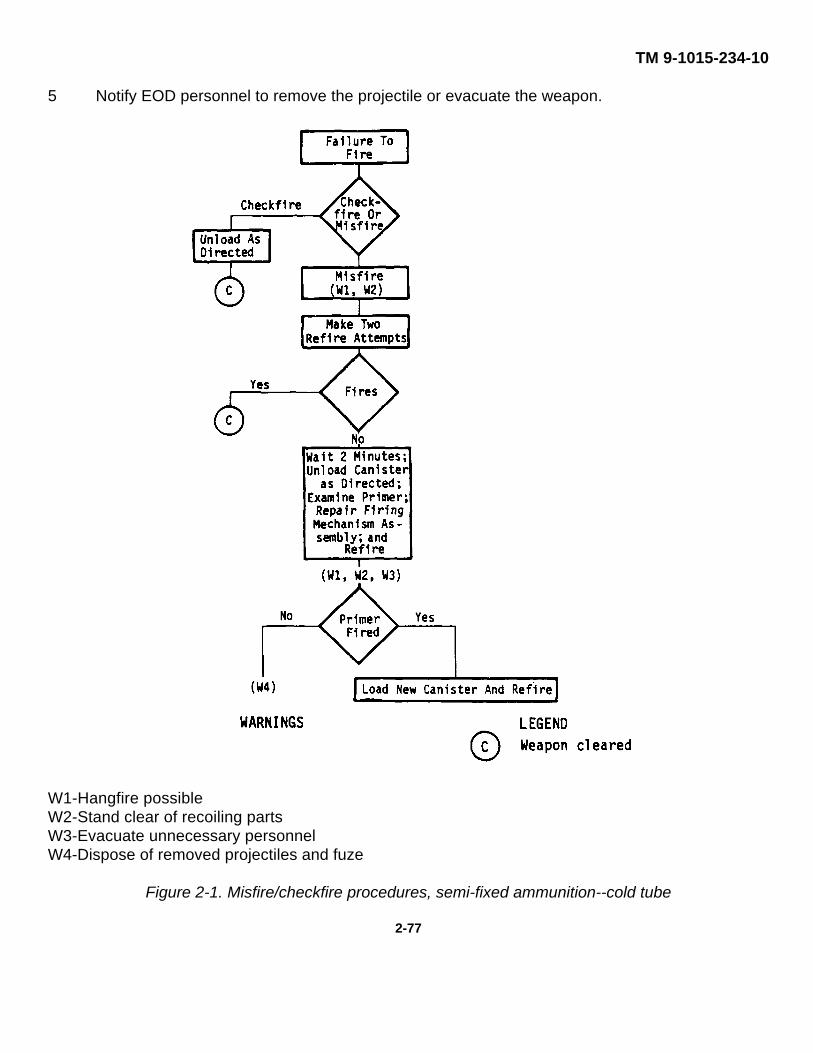
TM 9-1015-234-10
5 Notify EOD personnel to remove the projectile or evacuate the weapon.
W1-Hangfire possibleW2-Stand clear of recoiling partsW3-Evacuate unnecessary personnelW4-Dispose of removed projectiles and fuze
Figure 2-1. Misfire/checkfire procedures, semi-fixed ammunition--cold tube
2-77
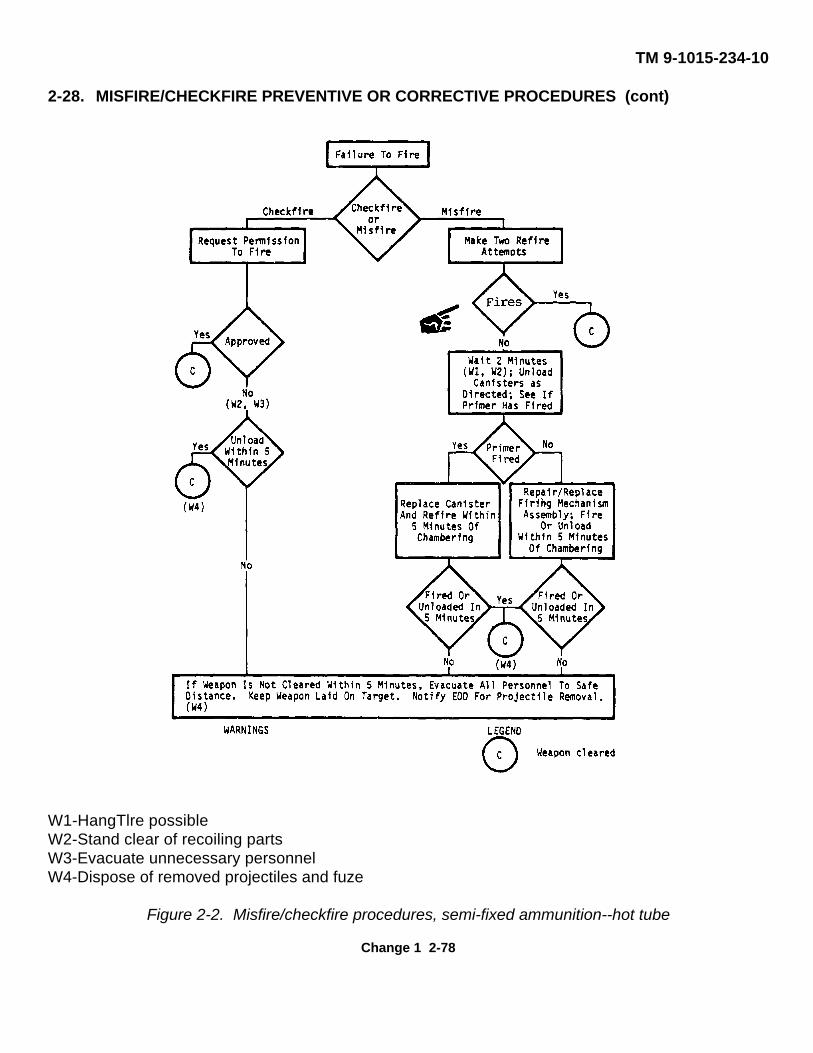
TM 9-1015-234-10
2-28. MISFIRE/CHECKFIRE PREVENTIVE OR CORRECTIVE PROCEDURES (cont)
W1-HangTlre possibleW2-Stand clear of recoiling partsW3-Evacuate unnecessary personnelW4-Dispose of removed projectiles and fuze
Figure 2-2. Misfire/checkfire procedures, semi-fixed ammunition--hot tube
Change 1 2-78
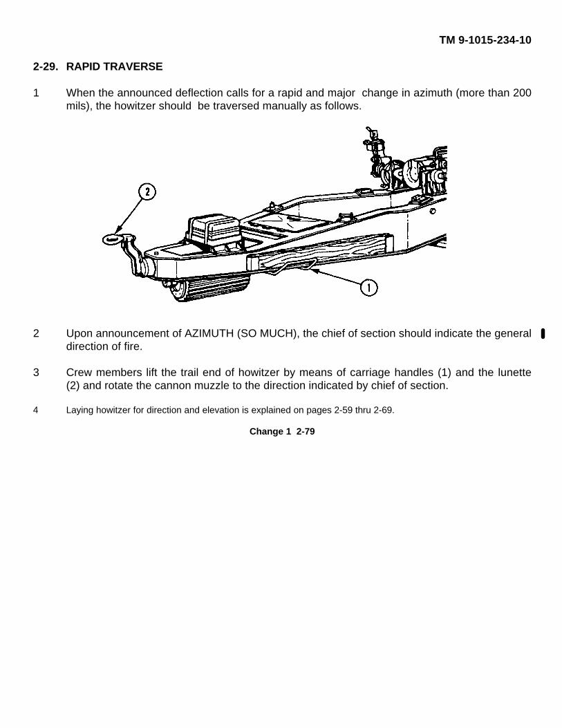
TM 9-1015-234-10
2-29. RAPID TRAVERSE
1 When the announced deflection calls for a rapid and major change in azimuth (more than 200mils), the howitzer should be traversed manually as follows.
2 Upon announcement of AZIMUTH (SO MUCH), the chief of section should indicate the generaldirection of fire.
3 Crew members lift the trail end of howitzer by means of carriage handles (1) and the lunette(2) and rotate the cannon muzzle to the direction indicated by chief of section.
4 Laying howitzer for direction and elevation is explained on pages 2-59 thru 2-69.
Change 1 2-79

TM 9-1015-234-10
2-30. MARCH ORDER--GENERAL PROCEDURES
WARNING
When handling radioactively illuminated fire control equipment, be awareof the radiation hazard procedures listed in the front of this manual.
WARNINGDo not store equipment of any kind inside the cannon tube. Foreignobjects inadvertently left in bore of cannon tube before firing can cause apremature explosion resulting in death or injury to personnel.
NOTEMarch order and preparation of howitzer for travel is accomplished undersupervision of the chief of section. When movement is ordered, the chiefof section commands MARCH ORDER. These general procedures mustbe accomplished regardless of whether the weapon will be towed orairlifted from the firing position.
1 The chief of section ensures the weapon is not loaded, and supervises the work of all cannoneers.
2 Cannoneer no. 1 inspects the collimator for damage and proper illumination, covers the collimator, and preparesit for travel.
3 ATC retrieves the aiming posts, inspects aiming posts for damage, checks illumination of aiming post lights, andprepares for travel.
4 The other crew members prepare ammunition for travel. (Ammunition repacking requirements are explained onpage 4-16.)
5 The gunner removes the M113A1 pantel and prepares it and M134A1 mount for travel as follows:
a. Places the traversing handwheel assembly in folded position.
b. Sets M113A1 pantel azimuth counter to read 3200.
Change 1 2-80
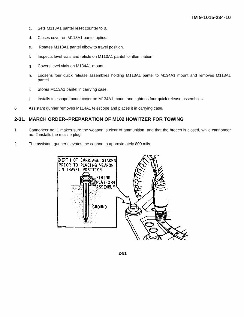
TM 9-1015-234-10
c. Sets M113A1 pantel reset counter to 0.
d. Closes cover on M113A1 pantel optics.
e. Rotates M113A1 pantel elbow to travel position.
f. Inspects level vials and reticle on M113A1 pantel for illumination.
g. Covers level vials on M134A1 mount.
h. Loosens four quick release assemblies holding M113A1 pantel to M134A1 mount and removes M113A1pantel.
i. Stores M113A1 pantel in carrying case.
j. Installs telescope mount cover on M134A1 mount and tightens four quick release assemblies.
6 Assistant gunner removes M114A1 telescope and places it in carrying case.
2-31. MARCH ORDER--PREPARATION OF M102 HOWITZER FOR TOWING
1 Cannoneer no. 1 makes sure the weapon is clear of ammunition and that the breech is closed, while cannoneerno. 2 installs the muzzle plug.
2 The assistant gunner elevates the cannon to approximately 800 mils.
2-81
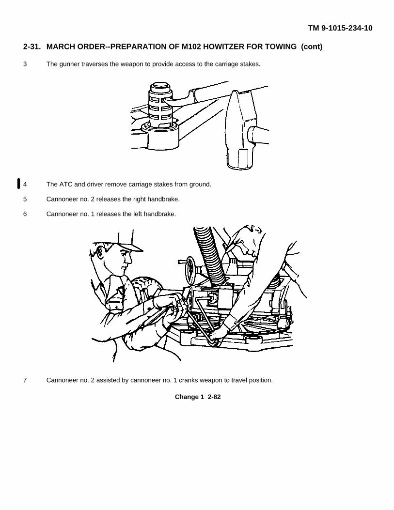
TM 9-1015-234-10
2-31. MARCH ORDER--PREPARATION OF M102 HOWITZER FOR TOWING (cont)
3 The gunner traverses the weapon to provide access to the carriage stakes.
4 The ATC and driver remove carriage stakes from ground.
5 Cannoneer no. 2 releases the right handbrake.
6 Cannoneer no. 1 releases the left handbrake.
7 Cannoneer no. 2 assisted by cannoneer no. 1 cranks weapon to travel position.
Change 1 2-82
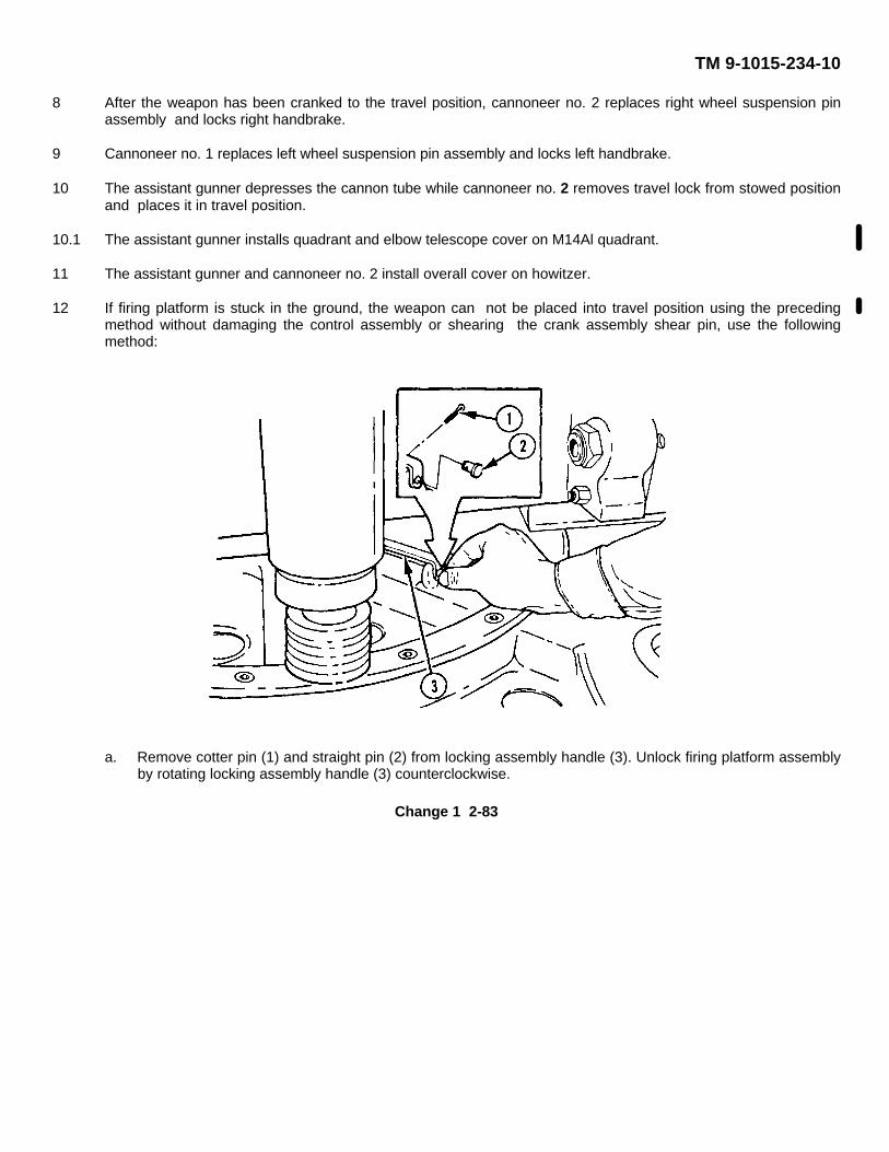
TM 9-1015-234-10
8 After the weapon has been cranked to the travel position, cannoneer no. 2 replaces right wheel suspension pinassembly and locks right handbrake.
9 Cannoneer no. 1 replaces left wheel suspension pin assembly and locks left handbrake.
10 The assistant gunner depresses the cannon tube while cannoneer no. 2 removes travel lock from stowed positionand places it in travel position.
10.1 The assistant gunner installs quadrant and elbow telescope cover on M14Al quadrant.
11 The assistant gunner and cannoneer no. 2 install overall cover on howitzer.
12 If firing platform is stuck in the ground, the weapon can not be placed into travel position using the precedingmethod without damaging the control assembly or shearing the crank assembly shear pin, use the followingmethod:
a. Remove cotter pin (1) and straight pin (2) from locking assembly handle (3). Unlock firing platform assemblyby rotating locking assembly handle (3) counterclockwise.
Change 1 2-83
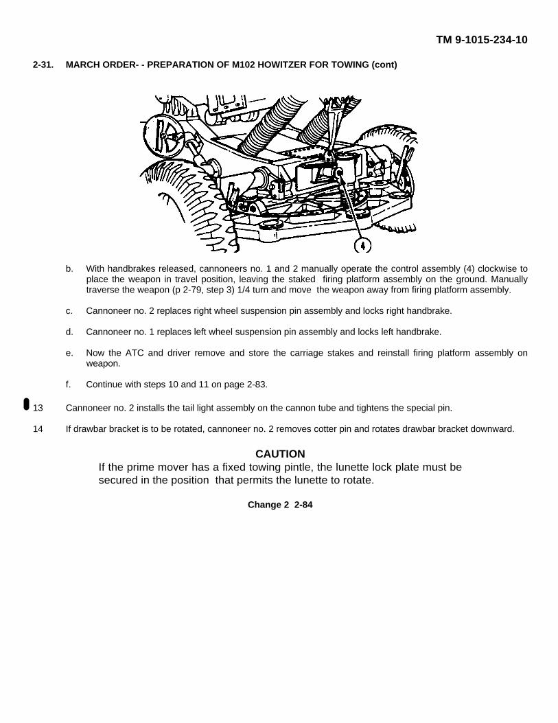
TM 9-1015-234-10
2-31. MARCH ORDER- - PREPARATION OF M102 HOWITZER FOR TOWING (cont)
b. With handbrakes released, cannoneers no. 1 and 2 manually operate the control assembly (4) clockwise toplace the weapon in travel position, leaving the staked firing platform assembly on the ground. Manuallytraverse the weapon (p 2-79, step 3) 1/4 turn and move the weapon away from firing platform assembly.
c. Cannoneer no. 2 replaces right wheel suspension pin assembly and locks right handbrake.
d. Cannoneer no. 1 replaces left wheel suspension pin assembly and locks left handbrake.
e. Now the ATC and driver remove and store the carriage stakes and reinstall firing platform assembly onweapon.
f. Continue with steps 10 and 11 on page 2-83.
13 Cannoneer no. 2 installs the tail light assembly on the cannon tube and tightens the special pin.
14 If drawbar bracket is to be rotated, cannoneer no. 2 removes cotter pin and rotates drawbar bracket downward.
CAUTIONIf the prime mover has a fixed towing pintle, the lunette lock plate must besecured in the position that permits the lunette to rotate.
Change 2 2-84
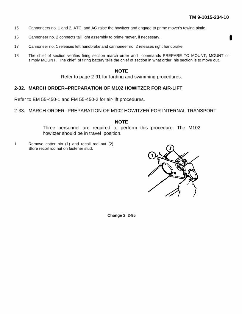
TM 9-1015-234-10
15 Cannoneers no. 1 and 2, ATC, and AG raise the howitzer and engage to prime mover's towing pintle.
16 Cannoneer no. 2 connects tail light assembly to prime mover, if necessary.
17 Cannoneer no. 1 releases left handbrake and cannoneer no. 2 releases right handbrake.
18 The chief of section verifies firing section march order and commands PREPARE TO MOUNT, MOUNT orsimply MOUNT. The chief of firing battery tells the chief of section in what order his section is to move out.
NOTERefer to page 2-91 for fording and swimming procedures.
2-32. MARCH ORDER--PREPARATION OF M102 HOWITZER FOR AIR-LIFT
Refer to EM 55-450-1 and FM 55-450-2 for air-lift procedures.
2-33. MARCH ORDER--PREPARATION OF M102 HOWITZER FOR INTERNAL TRANSPORT
NOTEThree personnel are required to perform this procedure. The M102howitzer should be in travel position.
1 Remove cotter pin (1) and recoil rod nut (2).Store recoil rod nut on fastener stud.
Change 2 2-85
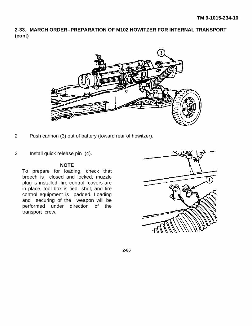
TM 9-1015-234-10
2-33. MARCH ORDER--PREPARATION OF M102 HOWITZER FOR INTERNAL TRANSPORT(cont)
2 Push cannon (3) out of battery (toward rear of howitzer).
3 Install quick release pin (4).
NOTETo prepare for loading, check thatbreech is closed and locked, muzzleplug is installed, fire control covers arein place, tool box is tied shut, and firecontrol equipment is padded. Loadingand securing of the weapon will beperformed under direction of thetransport crew.
2-86
TM 9-1015-234-10
Section IV. OPERATION UNDER UNUSUAL CONDITIONS
2-34. GENERAL
This section contains special instructions for operating and servicing the weapon under unusualconditions. Special care must be taken in cleaning and lubrication when extremes in temperature,humidity, and terrain conditions are present or anticipated, in addition to performing all normalpreventive maintenance services. Proper cleaning, lubrication, and storage and handling of oil andlubricants not only ensure proper operation and functioning but also guard against excessive wear ofthe working parts and deterioration of the materiel. See lubrication instructions beginning on page 3-1.
2-35. OPERATION IN EXTREME COLD WEATHER CONDITIONS
a. General Problems.
(1) Extensive preparation of materiel scheduled for operation in extreme cold weather is necessary.Generally, extreme cold will cause lubricants to thicken or congeal.
CAUTIONIt is important that the approved practices and precautions be followed.FM 9-207 contains general cold weather information applicable to theM102 howitzer. It must be considered an essential part of this technicalmanual.
(2) For description of operation in extreme cold, refer to FM 31-70, FM 31-71, and FM 9-207.
b. Fire Control Equipment.
(1) When not in use, fire control equipment should be kept covered in the proper carrying cases orproperly stowed.
(2) Do not let snow or ice accumulate on equipment. Moving parts must be kept free of moisture.
(3) Use only dry rags (item 22, app D) and dry lens paper (item 21, app D) for cleaning.
(4) Do not grasp metal parts such as knobs, levers, covers, etc., with bare hands.
2-87
TM 9-1015-234-10
2-35. OPERATION IN EXTREME COLD WEATHER CONDITIONS (cont)
(5) Working parts may operate or function sluggishly. The operator should be able to differentiatebetween sluggishness and lack of movement because of built-in stops. Do not force movementsbeyond their stops.
c. Emplacement on Frozen or Rocky Ground. In extremely rocky or frozen ground it may be difficult orimpossible to use normal size carriage stakes. A 15-inch steel carriage stake, which can generally withstandthe driving force required to penetrate frozen or rocky ground, is available (p C-3). This carriage stakerequires less emplacement time and depth of penetration.
2-36. OPERATION IN EXTREME HOT WEATHER CONDITIONS
a. General Problems.
(1) In hot climates, the film of oil necessary for operation and preservation will quickly disappear. Inspectthe cannon and carriage daily, paying particular attention to hidden surfaces, such as bore andchamber, springs, spring seats, firing pin, and other likely places where corrosion might occur and notbe quickly noticed.
(2) Perspiration from the hands can help cause rusting. After handling, clean, wipe dry, and lubricate(p 3-1).
b. Ammunition Problems.
(1) Since explosives are adversely affected by high temperatures, ammunition must be protected fromsources of high temperatures including the direct rays of the sun. Elements in primers and fuzes areparticularly sensitive to high temperatures.
(2) Whenever practicable, white phosphorous-loaded smoke projectiles should be stored at temperaturesbelow the melting point (+111.40F (+44.11°C)) of the white phosphorous filler. If not practicable,white phosphorous rounds should be stored on their bases so that if the white phosphorous filler meltsit will resolidify with void spaces in the normal position (in the nose of the projectile) when thetemperature falls below its melting point. Premature explosions
2-88
TM 9-1015-234-10
have been caused by voids in the base end of the white phosphorous projectile and erraticperformance may result from voids in its side. Refer to chapter 4 for precautions inhandling ammunition in high temperature.
c. Tires. Keep tires covered with available materials to protect them from direct rays of the sun, to preventexcessive air pressure, and to prevent deterioration of rubber. Correct tire pressure is listed on page 1-12.
2-37. OPERATION IN HOT, DAMP, AND SALTY ATMOSPHERE
a. Materiel should be inspected daily when being operated in hot, moist, and salty areas.
b. When the materiel is active, clean and lubricate the bore and exposed metal surfaces daily (p 3-1).
c. Moist and salty atmospheres can destroy the rust-preventive qualities of oils and greases. Inspect partsdaily for corrosion. Keep covers in place as much of the time as firing conditions permit.
CAUTION
Never use gasoline or any solvent to remove oil or grease spots fromcanvas covers.
Canvas deteriorates quickly in this atmosphere. Wet canvas should bedried thoroughly before folding to prevent mildew and deterioration.
d. For care and cleaning of canvas, refer to FM 21-15.
e. When the materiel is inactive, the unpainted parts should be covered with a film of CLP (item 9, app D). Allcovers should be in place.
f. Do not break moisture-resistant seals of ammunition containers until the ammunition is to be used.
g. Keep ammunition dry and free from mud, corrosion, or foreign matter. Provide proper drainage around thearea to keep it as dry as possible.
Change 1 2-89
TM 9-1015-234-10
2-37. OPERATION IN HOT, DAMP, AND SALTY ATMOSPHERE (cont)
h. Proximity (VT) fuzes must be protected against dampness. Although the fuzes are nearly waterproof, anyexposure to dampness may increase the number of duds. Rain or immersion in water will speed updeterioration. Especially in tropical climates, the storage time of unpacked fuzes should be kept to aminimum. Fuzes must be stored in their original sealed containers as long as it is practical.
i. Optical instruments are protected against moisture by pressurized nitrogen. If moisture is present, notifyorganizational maintenance.
2-38. OPERATION IN UNUSUAL TERRAIN CONDITIONS
a. Soft Terrain. When traveling on soft or muddy ground, reduce the tire inflation to increase flotation. Whenemplacing howitzer in soft terrain, use four 24-inch carriage stakes and four 38-inch carriage stakes (p B-5).
b. Snow or Ice.
(1) Snow. The many types of snow encountered make it impossible to establish firm rules for oversnowoperations. Experience in particular areas is required for accurate predictions of snow trafficability.Reconnaissance must be made.
(2) Ice. When ice crossings are contemplated, inspect first for cracks, ridges, and thin spots. Ice must bein contact with the water beneath it, as suspended ice is not strong.
(3) Side-Hill Travel. Traveling along the side of a hill in snow, ice, or soft ground must be avoided, as theweapon will not track properly.
c. Sand, Dust, and Dirt. Inspect and lubricate the materiel (p 3-1) frequently when operating in sandy orunusually dusty areas. Be careful to keep sand and dust out of mechanisms and oil receptacles whencarrying out inspection and lubrication operations and when making adjustments and repairs. Keep allcovers in place as much of the time as firing conditions permit. Shield parts from flying sand and dust withtarpaulins or with
2-90
TM 9-1015-234-10
the telescope and mount covers during disassembly and assembly operations. Whenbeginning an action in sandy or dusty areas, remove lubricants from exposed lubricated parts,situation permitting. Lubricants will pick up sand and dirt, forming an abrasive which will causerapid wear. With surfaces dry, there is less wear than when they are coated with lubricantcontaminated with sand or dirt. Clean and lubricate all exposed parts (p 3-1) after the actionis over.
2-39. FORDING OPERATIONS
a. Shallow-Water Fording.
(1) Cover the weapon with canvas covers provided to protect it from water being splashed against theweapon.
(2) If accidental complete submersion occurs, the weapon will be treated as described in step c below.
b. Deep-Water Fording. Refer to IM 9-238 for general information, description, and use of deep-water fordingkits.
c. After-Fording Operations .
(1) Immediately after weapon is towed from the water, if tactical situation permits, perform the followingservices:
(a) Notify organizational maintenance to remove the wheel and hub and brake drum assemblies, andthoroughly clean with cleaning compound and dry all working parts of the handbrakes and wheelbearings. Lubricate the assemblies in accordance with the lubrication instructions (p 3-1).
(b) Empty any water from the materiel and clean, dry, and apply the proper lubricant (p 3-1) to allexposed unpainted surfaces, paying special attention to the bore and chamber, the recoil rollers,and the gun cradle assembly rails.
Change 1 2-91

TM 9-1015-234-10
2-39. FORDING OPERATIONS (cont)
(2) If parts of the materiel are accidentally submerged or badly splashed, apply temporary preservative andnotify organizational maintenance personnel so that necessary complete disassembly, cleaning, andlubrication may be performed as soon as possible.
(3) Saltwater immersion greatly increases rusting and corrosion, especially on unpainted surfaces. It is mostimportant to remove all traces of saltwater and salt deposits from every part of the weapon. Applytemporary preservative and notify organizational maintenance so that necessary complete disassembly,cleaning, and lubrication may be performed as soon as possible.
2-40. NUCLEAR, BIOLOGICAL, AND CHEMICAL (NBC) DECONTAMINATION PROCEDURES
Perform NBC detection and decontamination procedures in accordance with FM 3-87 and FM 21-40,using DS-2 portable decontamination apparatus (TM 3-4230-204-12&P or unit SOP).
Change 1 2-92
TM 9-1015-234-10
CHAPTER 3
MAINTENANCE INSTRUCTIONS
Section I. LUBRICATION INSTRUCTIONS
3-1. GENERAL
a. Intervals are based on normal operation. You should lube more during constant use and lube less duringinactive periods. Relubricate after washing or fording. Clean fittings before lubricating. Clean parts with CLPor RBC, as specified. Dry before lubricating. DO NOT overlubricate; wipe off excess lubricant.
b. Dotted lines indicate lubrication points on both sides of the equipment. The level of maintenanceresponsible for each lube instruction is shown, and the lube instructions are divided into five sections basedon lubrication intervals (DAILY, WEEKLY, MONTHLY, SEMI-ANNUALLY, and ANNUALLY). An overallview showing lubrication points precedes each set of detailed notes for each interval. The lubricationinstructions are mandatory.
NOTECLP is the main lubricant for oil can points and after cleaning. Lubricatingoil, general purpose, special preservative (PL-S) or RBC may be used asan alternative unless specifically mentioned otherwise. Grease, aircraft,general purpose (GPG) may be substituted for grease, automotive andartillery (GAA) in lubrication procedures.
Daily lubing means lube once each day after weapon has been fired.
Change 1 3-1
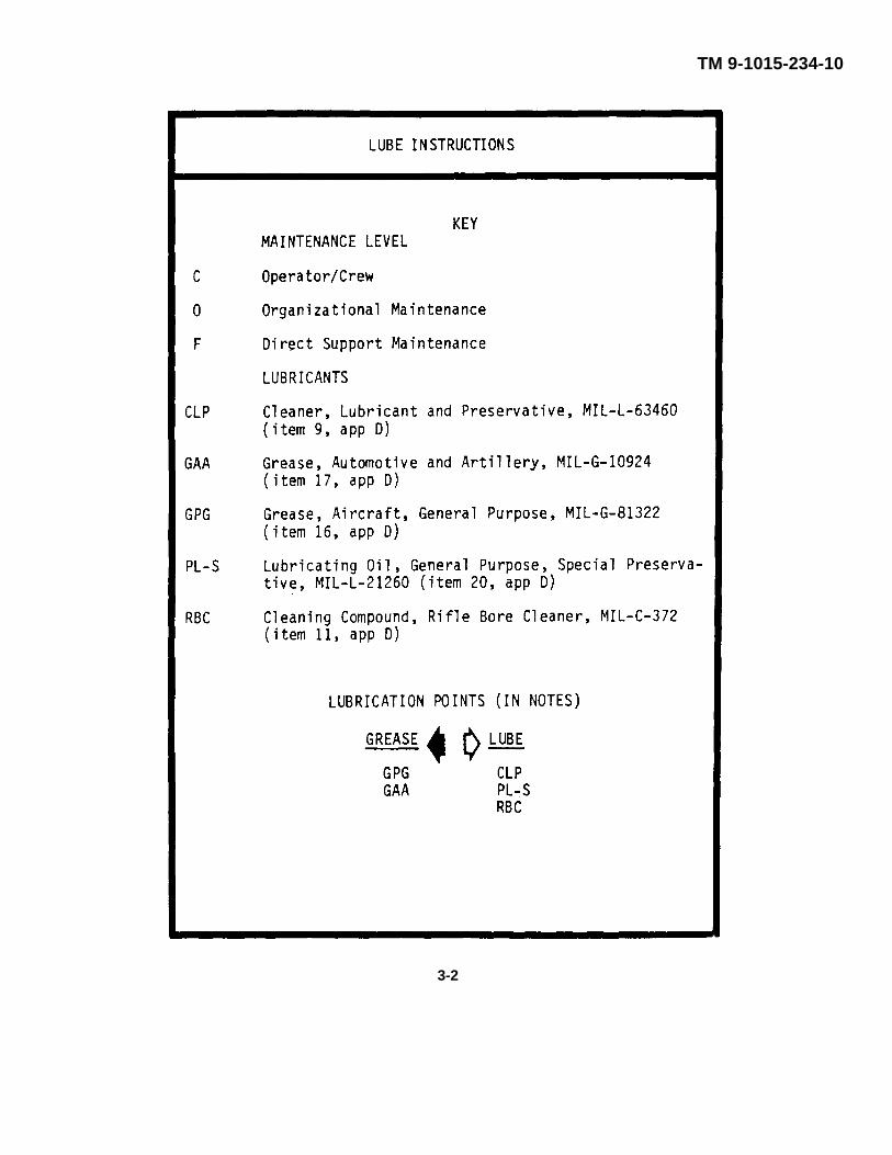
TM 9-1015-234-10
3-2
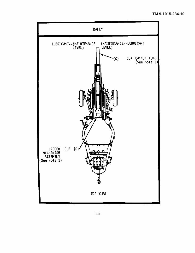
TM 9-1015-234-10
3-3
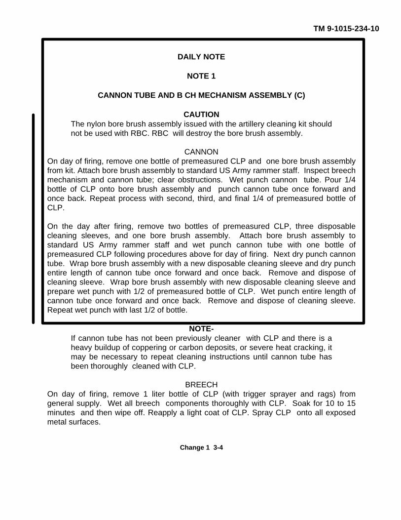
TM 9-1015-234-10
DAILY NOTE
NOTE 1
CANNON TUBE AND B CH MECHANISM ASSEMBLY (C)
CAUTIONThe nylon bore brush assembly issued with the artillery cleaning kit shouldnot be used with RBC. RBC will destroy the bore brush assembly.
CANNONOn day of firing, remove one bottle of premeasured CLP and one bore brush assemblyfrom kit. Attach bore brush assembly to standard US Army rammer staff. Inspect breechmechanism and cannon tube; clear obstructions. Wet punch cannon tube. Pour 1/4bottle of CLP onto bore brush assembly and punch cannon tube once forward andonce back. Repeat process with second, third, and final 1/4 of premeasured bottle ofCLP.
On the day after firing, remove two bottles of premeasured CLP, three disposablecleaning sleeves, and one bore brush assembly. Attach bore brush assembly tostandard US Army rammer staff and wet punch cannon tube with one bottle ofpremeasured CLP following procedures above for day of firing. Next dry punch cannontube. Wrap bore brush assembly with a new disposable cleaning sleeve and dry punchentire length of cannon tube once forward and once back. Remove and dispose ofcleaning sleeve. Wrap bore brush assembly with new disposable cleaning sleeve andprepare wet punch with 1/2 of premeasured bottle of CLP. Wet punch entire length ofcannon tube once forward and once back. Remove and dispose of cleaning sleeve.Repeat wet punch with last 1/2 of bottle.
NOTE-If cannon tube has not been previously cleaner with CLP and there is aheavy buildup of coppering or carbon deposits, or severe heat cracking, itmay be necessary to repeat cleaning instructions until cannon tube hasbeen thoroughly cleaned with CLP.
BREECHOn day of firing, remove 1 liter bottle of CLP (with trigger sprayer and rags) fromgeneral supply. Wet all breech components thoroughly with CLP. Soak for 10 to 15minutes and then wipe off. Reapply a light coat of CLP. Spray CLP onto all exposedmetal surfaces.
Change 1 3-4
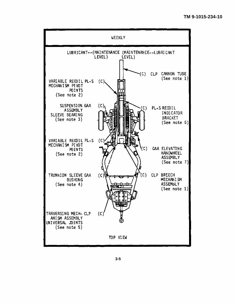
TM 9-1015-234-10
3-5
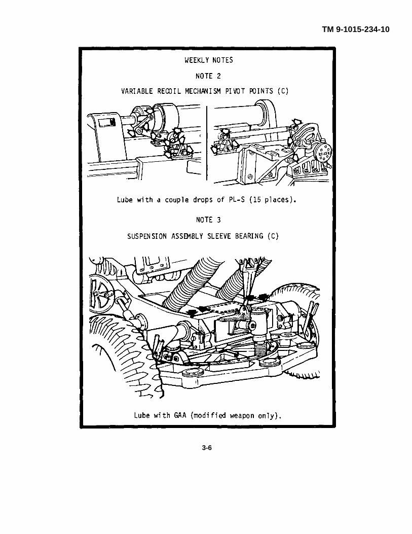
TM 9-1015-234-10
3-6
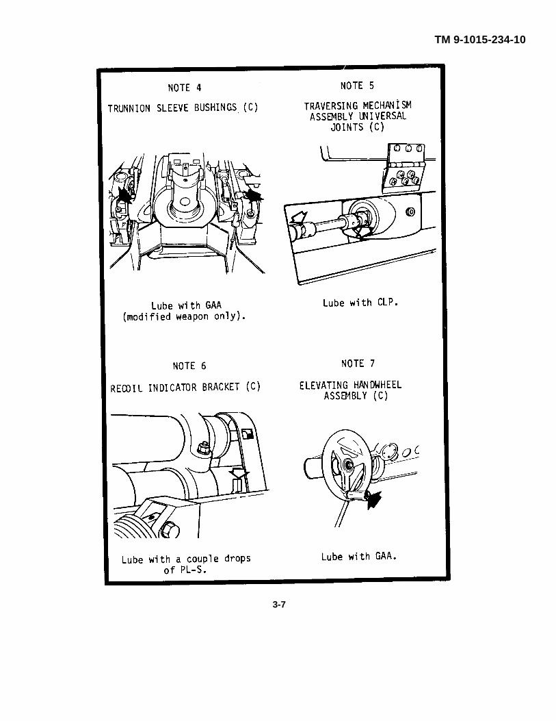
TM 9-1015-234-10
3-7
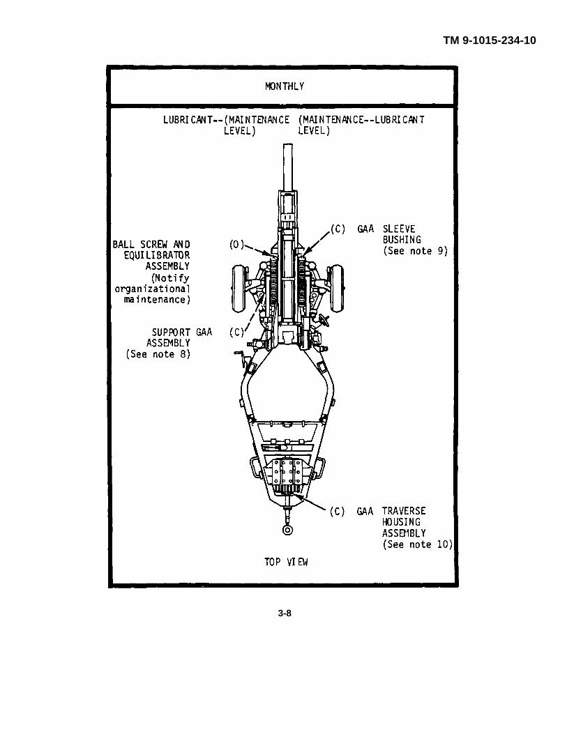
TM 9-1015-234-10
3-8
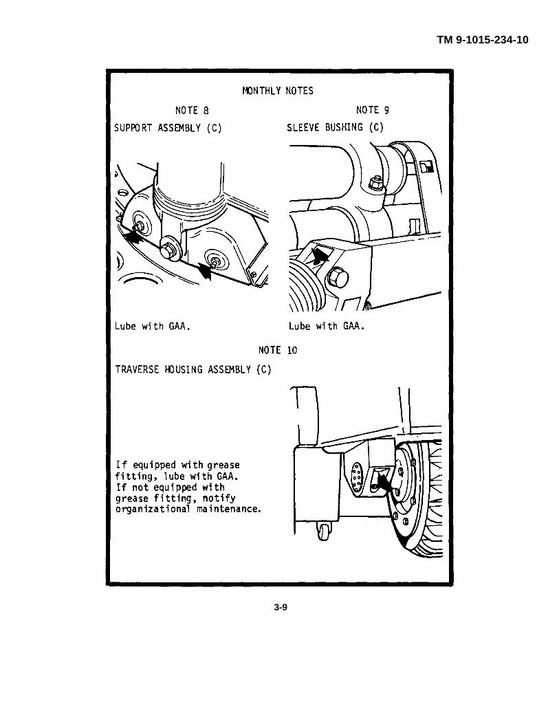
TM 9-1015-234-10
3-9
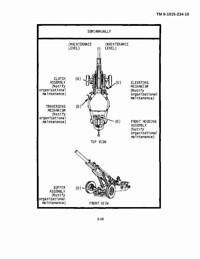
TM 9-1015-234-10
3-10
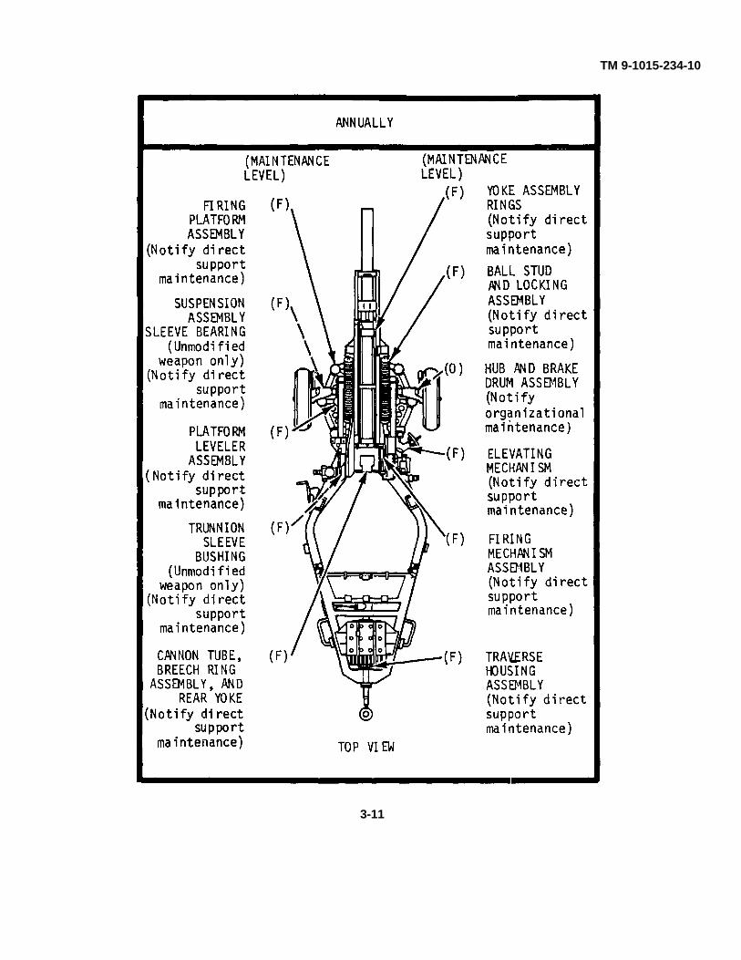
TM 9-1015-234-10
3-11
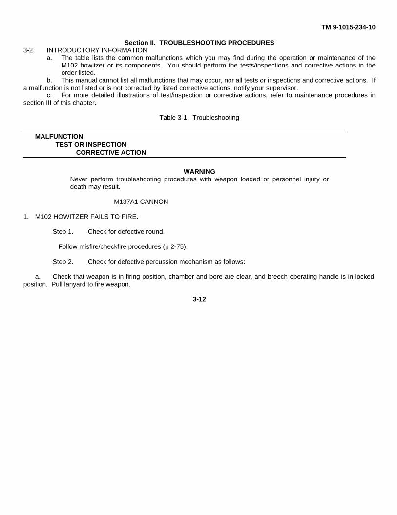
TM 9-1015-234-10
Section II. TROUBLESHOOTING PROCEDURES3-2. INTRODUCTORY INFORMATION
a. The table lists the common malfunctions which you may find during the operation or maintenance of theM102 howitzer or its components. You should perform the tests/inspections and corrective actions in theorder listed.
b. This manual cannot list all malfunctions that may occur, nor all tests or inspections and corrective actions. Ifa malfunction is not listed or is not corrected by listed corrective actions, notify your supervisor.
c. For more detailed illustrations of test/inspection or corrective actions, refer to maintenance procedures insection III of this chapter.
Table 3-1. Troubleshooting
MALFUNCTIONTEST OR INSPECTION
CORRECTIVE ACTION
WARNINGNever perform troubleshooting procedures with weapon loaded or personnel injury ordeath may result.
M137A1 CANNON
1. M102 HOWITZER FAILS TO FIRE.
Step 1. Check for defective round.
Follow misfire/checkfire procedures (p 2-75).
Step 2. Check for defective percussion mechanism as follows:
a. Check that weapon is in firing position, chamber and bore are clear, and breech operating handle is in lockedposition. Pull lanyard to fire weapon.
3-12
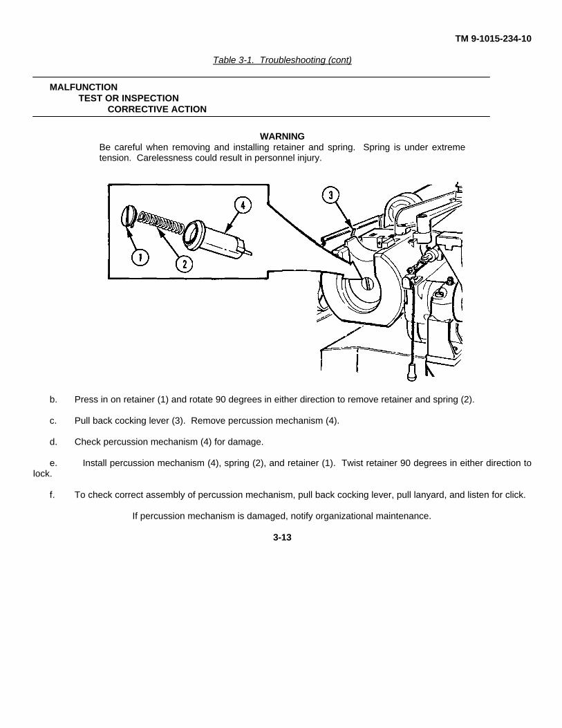
TM 9-1015-234-10
Table 3-1. Troubleshooting (cont)
MALFUNCTIONTEST OR INSPECTION
CORRECTIVE ACTION
WARNINGBe careful when removing and installing retainer and spring. Spring is under extremetension. Carelessness could result in personnel injury.
b. Press in on retainer (1) and rotate 90 degrees in either direction to remove retainer and spring (2).
c. Pull back cocking lever (3). Remove percussion mechanism (4).
d. Check percussion mechanism (4) for damage.
e. Install percussion mechanism (4), spring (2), and retainer (1). Twist retainer 90 degrees in either direction tolock.
f. To check correct assembly of percussion mechanism, pull back cocking lever, pull lanyard, and listen for click.
If percussion mechanism is damaged, notify organizational maintenance.
3-13
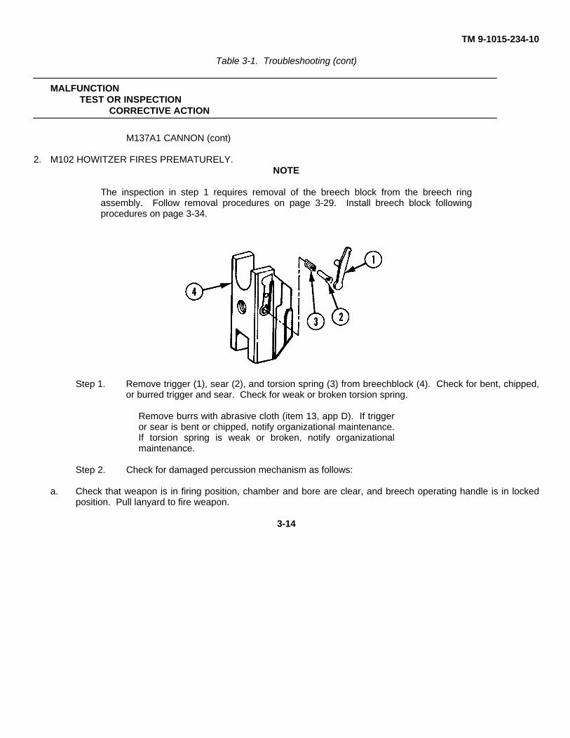
TM 9-1015-234-10
Table 3-1. Troubleshooting (cont)
MALFUNCTIONTEST OR INSPECTION
CORRECTIVE ACTION
M137A1 CANNON (cont)
2. M102 HOWITZER FIRES PREMATURELY.NOTE
The inspection in step 1 requires removal of the breech block from the breech ringassembly. Follow removal procedures on page 3-29. Install breech block followingprocedures on page 3-34.
Step 1. Remove trigger (1), sear (2), and torsion spring (3) from breechblock (4). Check for bent, chipped,or burred trigger and sear. Check for weak or broken torsion spring.
Remove burrs with abrasive cloth (item 13, app D). If triggeror sear is bent or chipped, notify organizational maintenance.If torsion spring is weak or broken, notify organizationalmaintenance.
Step 2. Check for damaged percussion mechanism as follows:
a. Check that weapon is in firing position, chamber and bore are clear, and breech operating handle is in lockedposition. Pull lanyard to fire weapon.
3-14
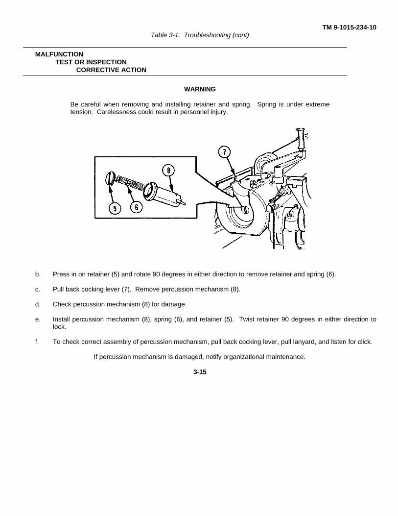
TM 9-1015-234-10Table 3-1. Troubleshooting (cont)
MALFUNCTIONTEST OR INSPECTION
CORRECTIVE ACTION
WARNING
Be careful when removing and installing retainer and spring. Spring is under extremetension. Carelessness could result in personnel injury.
b. Press in on retainer (5) and rotate 90 degrees in either direction to remove retainer and spring (6).
c. Pull back cocking lever (7). Remove percussion mechanism (8).
d. Check percussion mechanism (8) for damage.
e. Install percussion mechanism (8), spring (6), and retainer (5). Twist retainer 90 degrees in either direction tolock.
f. To check correct assembly of percussion mechanism, pull back cocking lever, pull lanyard, and listen for click.
If percussion mechanism is damaged, notify organizational maintenance.
3-15
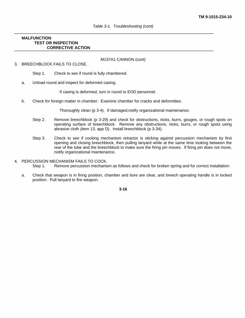
TM 9-1015-234-10
Table 3-1. Troubleshooting (cont)
MALFUNCTIONTEST OR INSPECTION
CORRECTIVE ACTION
M137A1 CANNON (cont)3. BREECHBLOCK FAILS TO CLOSE.
Step 1. Check to see if round is fully chambered.
a. Unload round and inspect for deformed casing.
If casing is deformed, turn in round to EOD personnel.
b. Check for foreign matter in chamber. Examine chamber for cracks and deformities.
Thoroughly clean (p 3-4). If damaged,notify organizational maintenance.
Step 2. Remove breechblock (p 3-29) and check for obstructions, nicks, burrs, gouges, or rough spots onoperating surface of breechblock. Remove any obstructions, nicks, burrs, or rough spots usingabrasive cloth (item 13, app D). Install breechblock (p 3-34).
Step 3. Check to see if cocking mechanism retractor is sticking against percussion mechanism by firstopening and closing breechblock, then pulling lanyard while at the same time looking between therear of the tube and the breechblock to make sure the firing pin moves. If firing pin does not move,notify organizational maintenance.
4. PERCUSSION MECHANISM FAILS TO COCK.Step 1. Remove percussion mechanism as follows and check for broken spring and for correct installation:
a. Check that weapon is in firing position, chamber and bore are clear, and breech operating handle is in lockedposition. Pull lanyard to fire weapon.
3-16
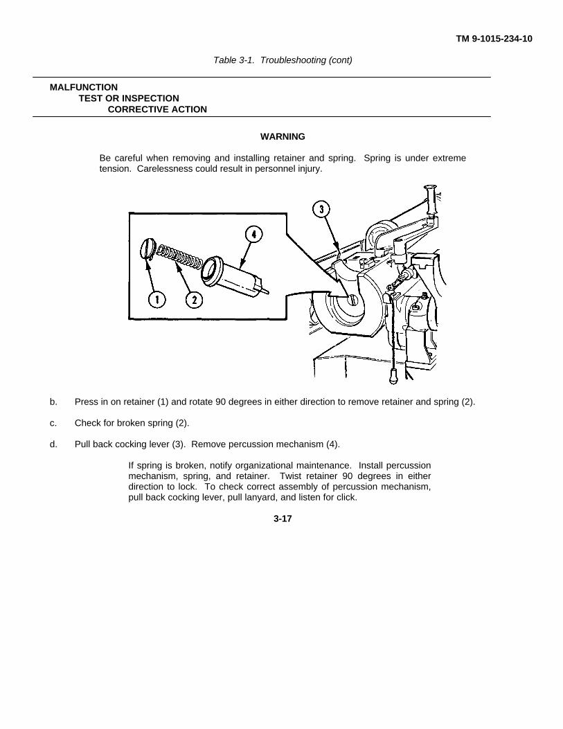
TM 9-1015-234-10
Table 3-1. Troubleshooting (cont)
MALFUNCTIONTEST OR INSPECTION
CORRECTIVE ACTION
WARNING
Be careful when removing and installing retainer and spring. Spring is under extremetension. Carelessness could result in personnel injury.
b. Press in on retainer (1) and rotate 90 degrees in either direction to remove retainer and spring (2).
c. Check for broken spring (2).
d. Pull back cocking lever (3). Remove percussion mechanism (4).
If spring is broken, notify organizational maintenance. Install percussionmechanism, spring, and retainer. Twist retainer 90 degrees in eitherdirection to lock. To check correct assembly of percussion mechanism,pull back cocking lever, pull lanyard, and listen for click.
3-17
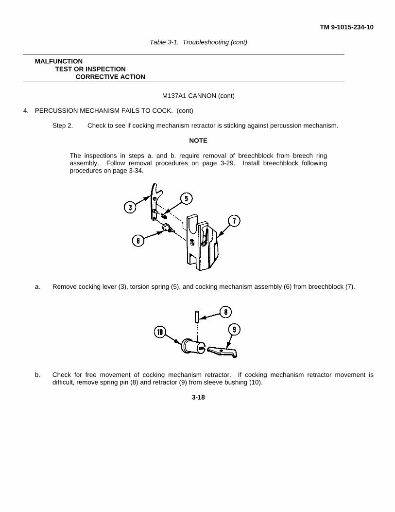
TM 9-1015-234-10
Table 3-1. Troubleshooting (cont)
MALFUNCTIONTEST OR INSPECTION
CORRECTIVE ACTION
M137A1 CANNON (cont)
4. PERCUSSION MECHANISM FAILS TO COCK. (cont)
Step 2. Check to see if cocking mechanism retractor is sticking against percussion mechanism.
NOTE
The inspections in steps a. and b. require removal of breechblock from breech ringassembly. Follow removal procedures on page 3-29. Install breechblock followingprocedures on page 3-34.
a. Remove cocking lever (3), torsion spring (5), and cocking mechanism assembly (6) from breechblock (7).
b. Check for free movement of cocking mechanism retractor. If cocking mechanism retractor movement isdifficult, remove spring pin (8) and retractor (9) from sleeve bushing (10).
3-18
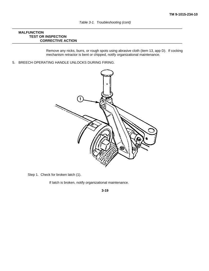
TM 9-1015-234-10
Table 3-1. Troubleshooting (cont)
MALFUNCTIONTEST OR INSPECTION
CORRECTIVE ACTION
Remove any nicks, burrs, or rough spots using abrasive cloth (item 13, app D). If cockingmechanism retractor is bent or chipped, notify organizational maintenance.
5. BREECH OPERATING HANDLE UNLOCKS DURING FIRING.
Step 1. Check for broken latch (1).
If latch is broken, notify organizational maintenance.
3-19
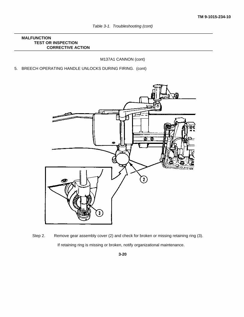
TM 9-1015-234-10
Table 3-1. Troubleshooting (cont)
MALFUNCTIONTEST OR INSPECTION
CORRECTIVE ACTION
M137A1 CANNON (cont)
5. BREECH OPERATING HANDLE UNLOCKS DURING FIRING. (cont)
Step 2. Remove gear assembly cover (2) and check for broken or missing retaining ring (3).
If retaining ring is missing or broken, notify organizational maintenance.
3-20
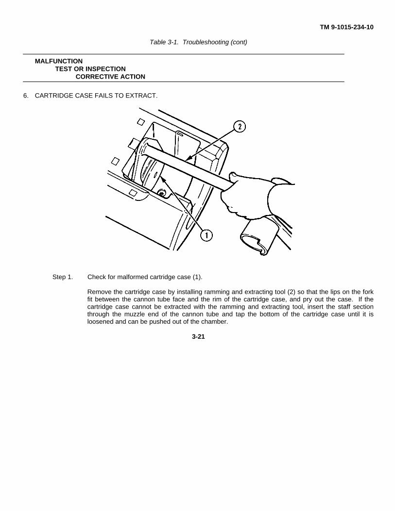
TM 9-1015-234-10
Table 3-1. Troubleshooting (cont)
MALFUNCTIONTEST OR INSPECTION
CORRECTIVE ACTION
6. CARTRIDGE CASE FAILS TO EXTRACT.
Step 1. Check for malformed cartridge case (1).
Remove the cartridge case by installing ramming and extracting tool (2) so that the lips on the forkfit between the cannon tube face and the rim of the cartridge case, and pry out the case. If thecartridge case cannot be extracted with the ramming and extracting tool, insert the staff sectionthrough the muzzle end of the cannon tube and tap the bottom of the cartridge case until it isloosened and can be pushed out of the chamber.
3-21
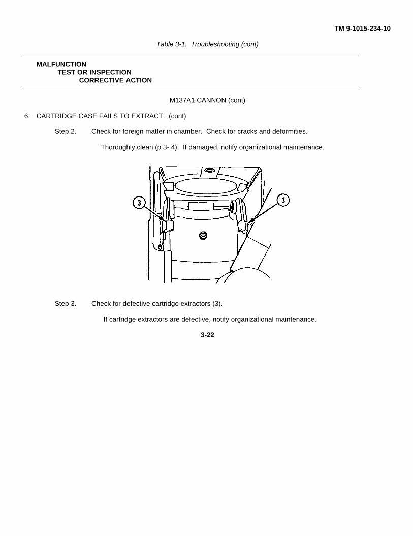
TM 9-1015-234-10
Table 3-1. Troubleshooting (cont)
MALFUNCTIONTEST OR INSPECTION
CORRECTIVE ACTION
M137A1 CANNON (cont)
6. CARTRIDGE CASE FAILS TO EXTRACT. (cont)
Step 2. Check for foreign matter in chamber. Check for cracks and deformities.
Thoroughly clean (p 3- 4). If damaged, notify organizational maintenance.
Step 3. Check for defective cartridge extractors (3).
If cartridge extractors are defective, notify organizational maintenance.
3-22
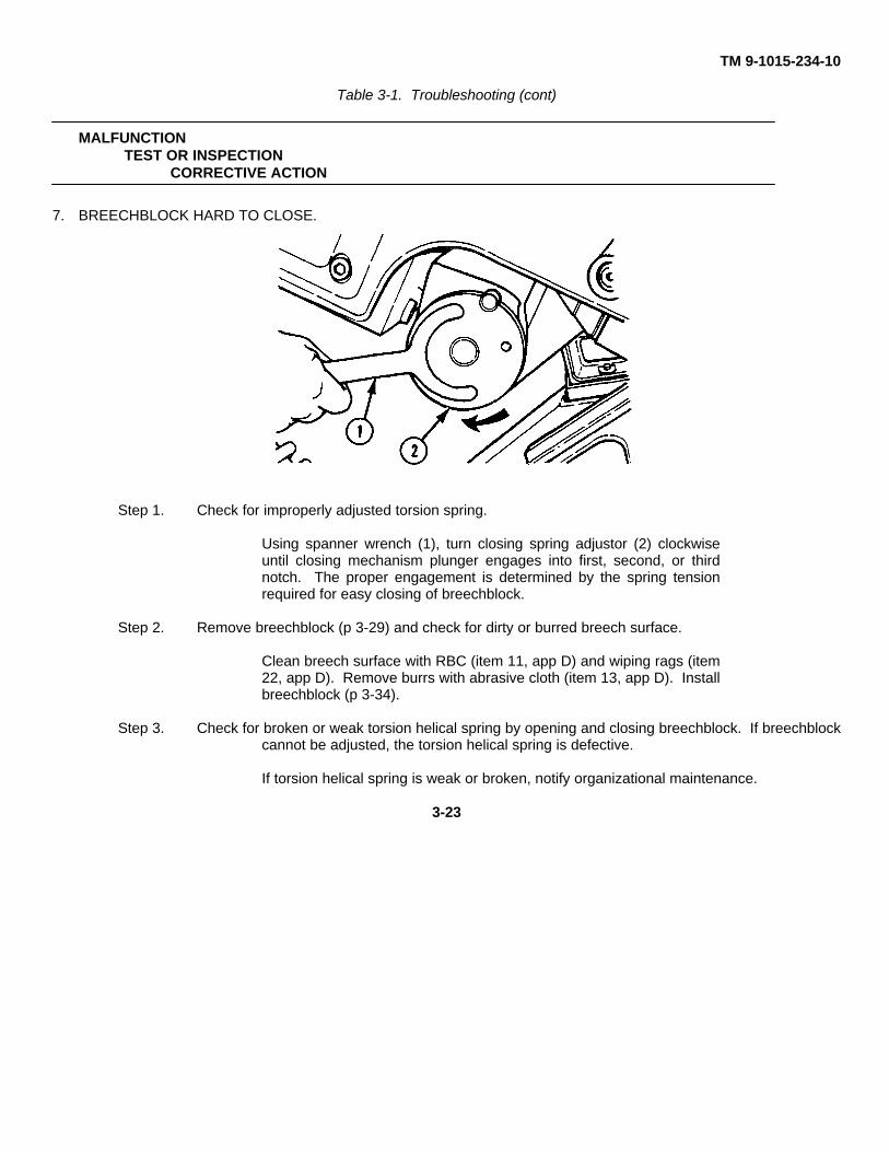
TM 9-1015-234-10
Table 3-1. Troubleshooting (cont)
MALFUNCTIONTEST OR INSPECTION
CORRECTIVE ACTION
7. BREECHBLOCK HARD TO CLOSE.
Step 1. Check for improperly adjusted torsion spring.
Using spanner wrench (1), turn closing spring adjustor (2) clockwiseuntil closing mechanism plunger engages into first, second, or thirdnotch. The proper engagement is determined by the spring tensionrequired for easy closing of breechblock.
Step 2. Remove breechblock (p 3-29) and check for dirty or burred breech surface.
Clean breech surface with RBC (item 11, app D) and wiping rags (item22, app D). Remove burrs with abrasive cloth (item 13, app D). Installbreechblock (p 3-34).
Step 3. Check for broken or weak torsion helical spring by opening and closing breechblock. If breechblockcannot be adjusted, the torsion helical spring is defective.
If torsion helical spring is weak or broken, notify organizational maintenance.
3-23
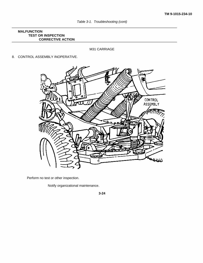
TM 9-1015-234-10
Table 3-1. Troubleshooting (cont)
MALFUNCTIONTEST OR INSPECTION
CORRECTIVE ACTION
M31 CARRIAGE
8. CONTROL ASSEMBLY INOPERATIVE.
Perform no test or other inspection.
Notify organizational maintenance.
3-24
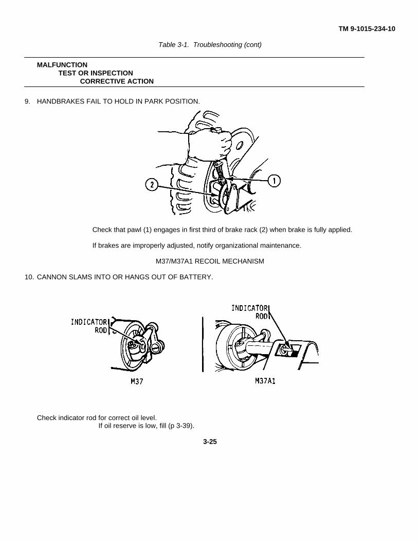
TM 9-1015-234-10
Table 3-1. Troubleshooting (cont)
MALFUNCTIONTEST OR INSPECTION
CORRECTIVE ACTION
9. HANDBRAKES FAIL TO HOLD IN PARK POSITION.
Check that pawl (1) engages in first third of brake rack (2) when brake is fully applied.
If brakes are improperly adjusted, notify organizational maintenance.
M37/M37A1 RECOIL MECHANISM
10. CANNON SLAMS INTO OR HANGS OUT OF BATTERY.
Check indicator rod for correct oil level.If oil reserve is low, fill (p 3-39).
3-25
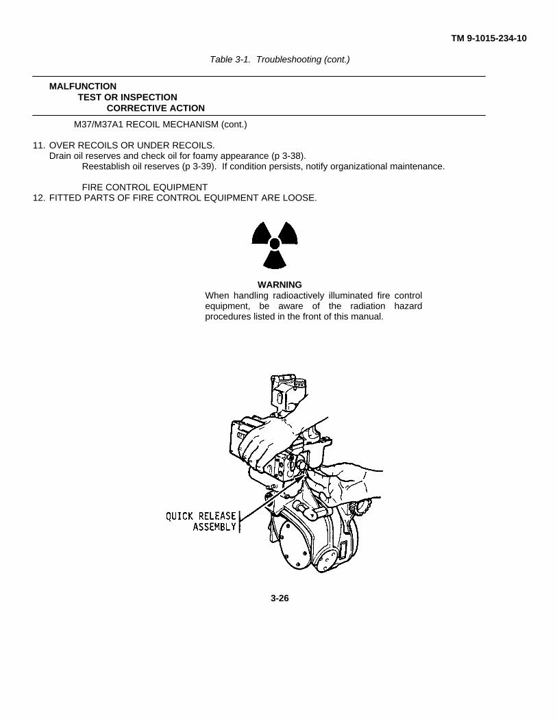
TM 9-1015-234-10
Table 3-1. Troubleshooting (cont.)
MALFUNCTIONTEST OR INSPECTION
CORRECTIVE ACTION
M37/M37A1 RECOIL MECHANISM (cont.)
11. OVER RECOILS OR UNDER RECOILS.Drain oil reserves and check oil for foamy appearance (p 3-38).
Reestablish oil reserves (p 3-39). If condition persists, notify organizational maintenance.
FIRE CONTROL EQUIPMENT12. FITTED PARTS OF FIRE CONTROL EQUIPMENT ARE LOOSE.
WARNINGWhen handling radioactively illuminated fire controlequipment, be aware of the radiation hazardprocedures listed in the front of this manual.
3-26
TM 9-1015-234-10Table 3-1. Troubleshooting (cont.)
MALFUNCTIONTEST OR INSPECTION
CORRECTIVE ACTION
Step 1. Check to see if quick release assemblies are tight.Tighten quick release assemblies.
Step 2. Check that lock wire is fastened to mounting screws.
If mounting screws are loose or missing, notify organizational maintenance.
13. MOISTURE IS IN FIRE CONTROL EQUIPMENT.No further inspection is required.
Notify organizational maintenance.
14. COUNTERS, LEVELS, OR RETICLES ARE NOT ILLUMINATED.
WARNING
Put fire control equipment in a plastic bag (item 1, app D), wash hands,and follow radioactive materials procedures in the front of this manual.Notify organizational maintenance and the radiological protection officer.
Perform no further test or inspection.
15. KNOBS DO NOT TURN FREELY.No further inspection is required.
Notify organizational maintenance.3-27
TM 9-1015-234-10Table 3-1. Troubleshooting (cont.)
MALFUNCTIONTEST OR INSPECTION
CORRECTIVE ACTION
FIRE CONTROL EQUIPMENT (cont)16. COUNTERS, RETICLES, OR LEVEL VIALS ARE BROKEN.
WARNINGPut fire control equipment in a plastic bag (item 1, app D), wash hands, and followradioactive materials procedures in the front of this manual. Notify organizationalmaintenance and the radiological protection officer. Perform no further test orinspection.
17. COLLIMATOR RETICLE IMAGE IS NOT SHARP.
Step 1. Check to see if optical lenses are dirty, wet, or fogged.
Notify organizational maintenance.
Step 2. Check to see if reticule is dirty.If reticule is dirty, notify organizational maintenance.
3-28
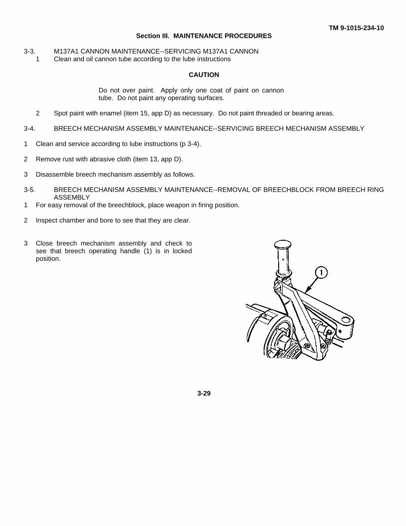
TM 9-1015-234-10Section III. MAINTENANCE PROCEDURES
3-3. M137A1 CANNON MAINTENANCE--SERVICING M137A1 CANNON1 Clean and oil cannon tube according to the lube instructions
CAUTION
Do not over paint. Apply only one coat of paint on cannontube. Do not paint any operating surfaces.
2 Spot paint with enamel (item 15, app D) as necessary. Do not paint threaded or bearing areas.
3-4. BREECH MECHANISM ASSEMBLY MAINTENANCE--SERVICING BREECH MECHANISM ASSEMBLY
1 Clean and service according to lube instructions (p 3-4).
2 Remove rust with abrasive cloth (item 13, app D).
3 Disassemble breech mechanism assembly as follows.
3-5. BREECH MECHANISM ASSEMBLY MAINTENANCE--REMOVAL OF BREECHBLOCK FROM BREECH RINGASSEMBLY
1 For easy removal of the breechblock, place weapon in firing position.
2 Inspect chamber and bore to see that they are clear.
3 Close breech mechanism assembly and check tosee that breech operating handle (1) is in lockedposition.
3-29
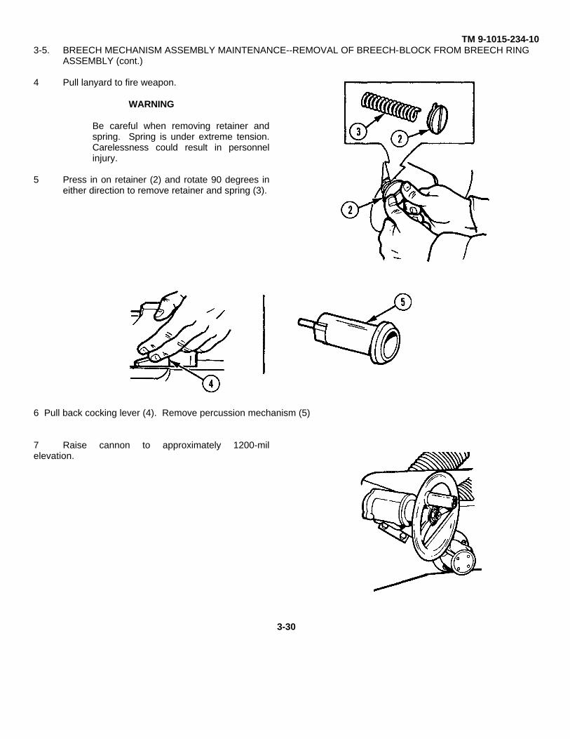
TM 9-1015-234-103-5. BREECH MECHANISM ASSEMBLY MAINTENANCE--REMOVAL OF BREECH-BLOCK FROM BREECH RING
ASSEMBLY (cont.)
4 Pull lanyard to fire weapon.
WARNING
Be careful when removing retainer andspring. Spring is under extreme tension.Carelessness could result in personnelinjury.
5 Press in on retainer (2) and rotate 90 degrees ineither direction to remove retainer and spring (3).
6 Pull back cocking lever (4). Remove percussion mechanism (5)
7 Raise cannon to approximately 1200-milelevation.
3-30
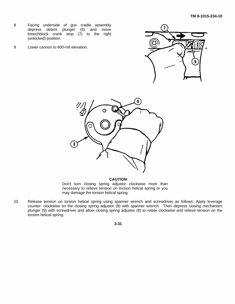
TM 9-1015-234-10
8 Facing underside of gun cradle assemblydepress detent plunger {6) and movebreechblock crank stop (7) to the right(unlocked) position.
9 Lower cannon to 600-mil elevation.
CAUTIONDon't turn closing spring adjustor clockwise more thannecessary to relieve tension on torsion helical spring or youmay damage the torsion helical spring.
10 Release tension on torsion helical spring using spanner wrench and screwdriver as follows: Apply leveragecounter- clockwise on the closing spring adjustor (8) with spanner wrench. Then depress closing mechanismplunger (9) with screwdriver and allow closing spring adjustor (8) to rotate clockwise and relieve tension on thetorsion helical spring.
3-31
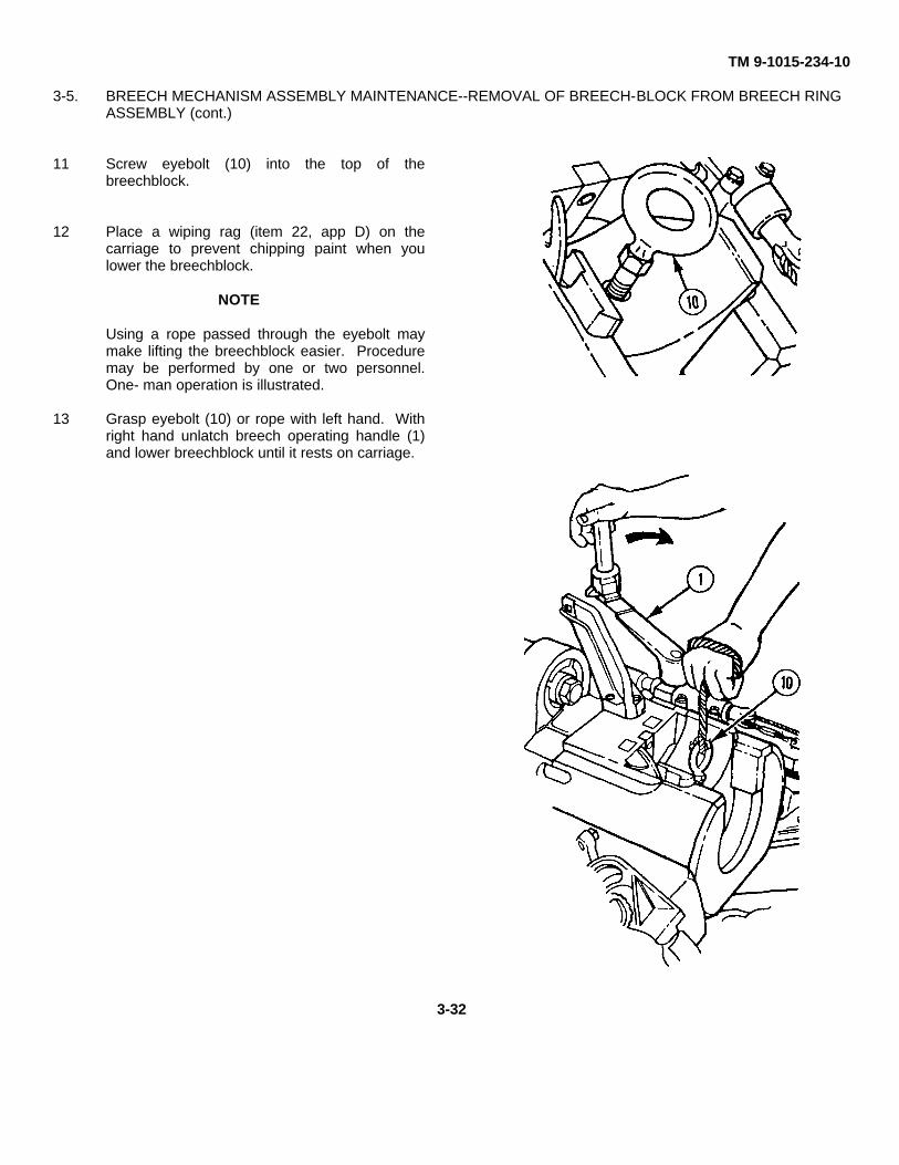
TM 9-1015-234-10
3-5. BREECH MECHANISM ASSEMBLY MAINTENANCE--REMOVAL OF BREECH-BLOCK FROM BREECH RINGASSEMBLY (cont.)
11 Screw eyebolt (10) into the top of thebreechblock.
12 Place a wiping rag (item 22, app D) on thecarriage to prevent chipping paint when youlower the breechblock.
NOTE
Using a rope passed through the eyebolt maymake lifting the breechblock easier. Proceduremay be performed by one or two personnel.One- man operation is illustrated.
13 Grasp eyebolt (10) or rope with left hand. Withright hand unlatch breech operating handle (1)and lower breechblock until it rests on carriage.
3-32
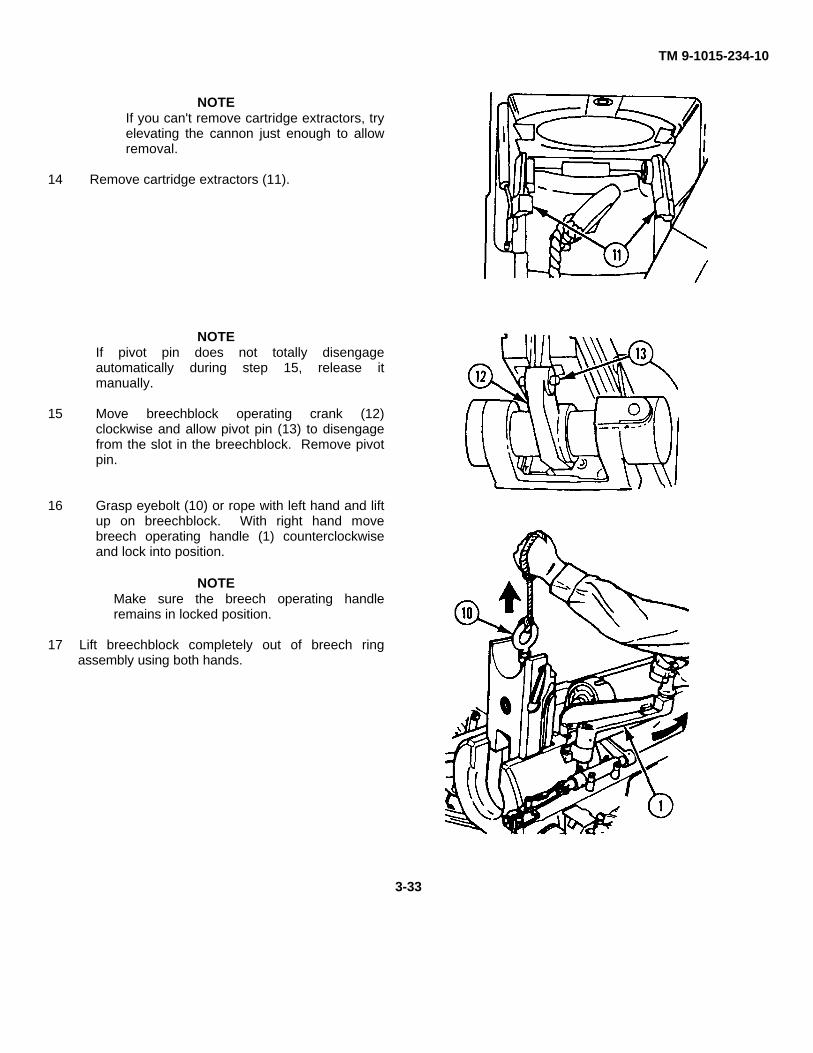
TM 9-1015-234-10
NOTEIf you can't remove cartridge extractors, tryelevating the cannon just enough to allowremoval.
14 Remove cartridge extractors (11).
NOTEIf pivot pin does not totally disengageautomatically during step 15, release itmanually.
15 Move breechblock operating crank (12)clockwise and allow pivot pin (13) to disengagefrom the slot in the breechblock. Remove pivotpin.
16 Grasp eyebolt (10) or rope with left hand and liftup on breechblock. With right hand movebreech operating handle (1) counterclockwiseand lock into position.
NOTEMake sure the breech operating handleremains in locked position.
17 Lift breechblock completely out of breech ringassembly using both hands.
3-33
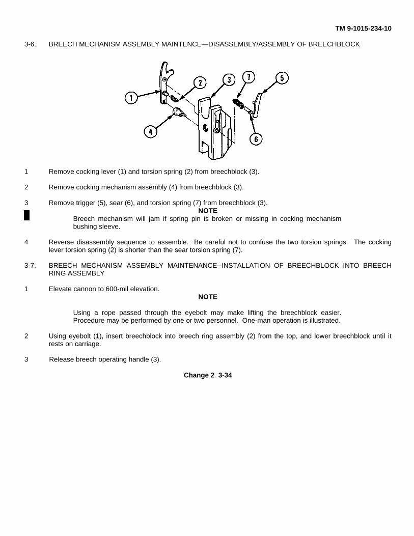
TM 9-1015-234-10
3-6. BREECH MECHANISM ASSEMBLY MAINTENCE—DISASSEMBLY/ASSEMBLY OF BREECHBLOCK
1 Remove cocking lever (1) and torsion spring (2) from breechblock (3).
2 Remove cocking mechanism assembly (4) from breechblock (3).
3 Remove trigger (5), sear (6), and torsion spring (7) from breechblock (3).NOTE
Breech mechanism will jam if spring pin is broken or missing in cocking mechanismbushing sleeve.
4 Reverse disassembly sequence to assemble. Be careful not to confuse the two torsion springs. The cockinglever torsion spring (2) is shorter than the sear torsion spring (7).
3-7. BREECH MECHANISM ASSEMBLY MAINTENANCE--INSTALLATION OF BREECHBLOCK INTO BREECHRING ASSEMBLY
1 Elevate cannon to 600-mil elevation.NOTE
Using a rope passed through the eyebolt may make lifting the breechblock easier.Procedure may be performed by one or two personnel. One-man operation is illustrated.
2 Using eyebolt (1), insert breechblock into breech ring assembly (2) from the top, and lower breechblock until itrests on carriage.
3 Release breech operating handle (3).
Change 2 3-34
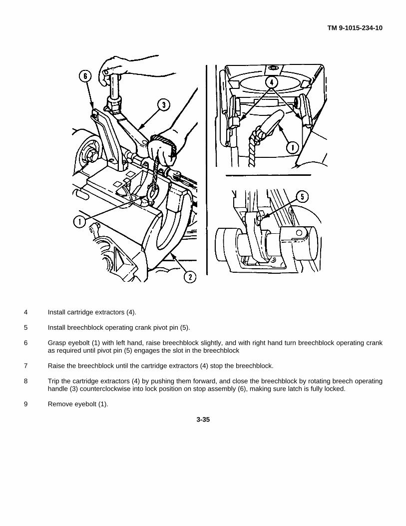
TM 9-1015-234-10
4 Install cartridge extractors (4).
5 Install breechblock operating crank pivot pin (5).
6 Grasp eyebolt (1) with left hand, raise breechblock slightly, and with right hand turn breechblock operating crankas required until pivot pin (5) engages the slot in the breechblock
7 Raise the breechblock until the cartridge extractors (4) stop the breechblock.
8 Trip the cartridge extractors (4) by pushing them forward, and close the breechblock by rotating breech operatinghandle (3) counterclockwise into lock position on stop assembly (6), making sure latch is fully locked.
9 Remove eyebolt (1).
3-35
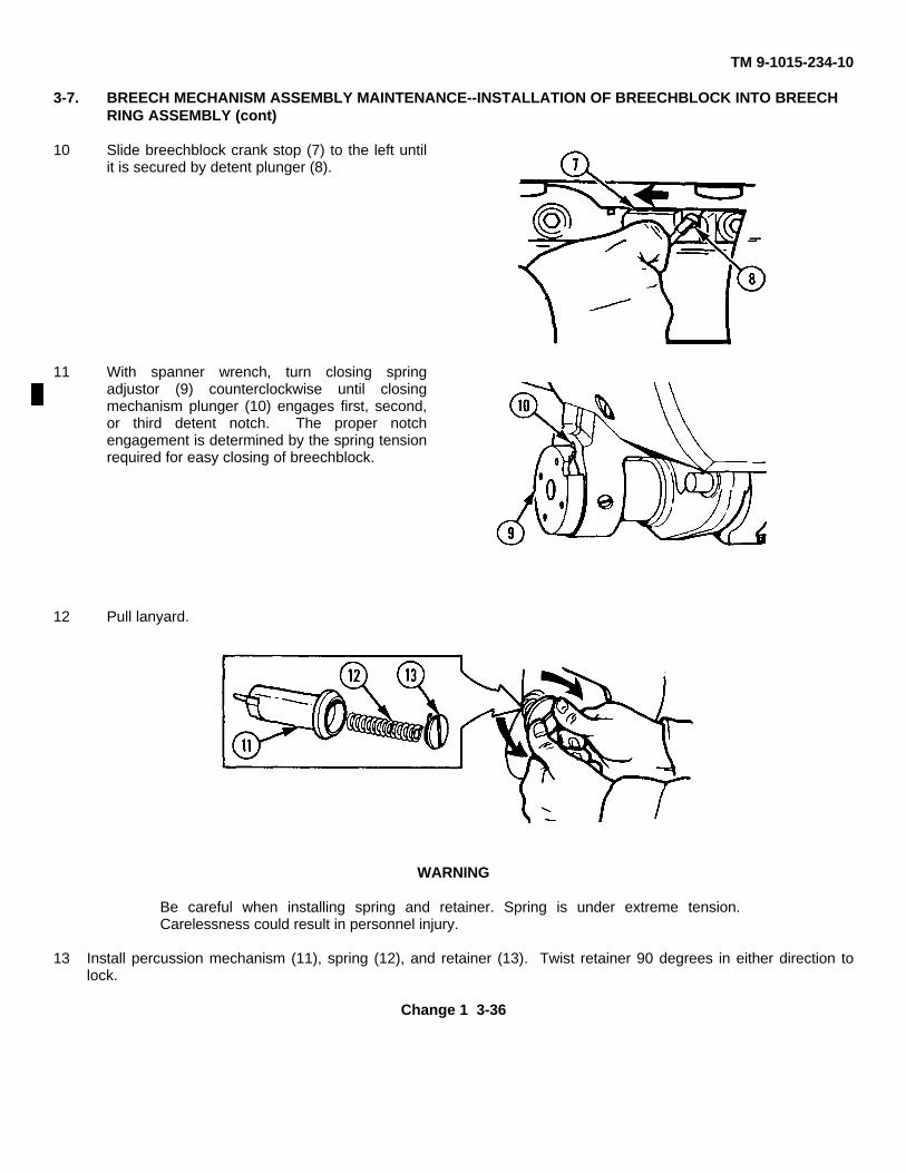
TM 9-1015-234-10
3-7. BREECH MECHANISM ASSEMBLY MAINTENANCE--INSTALLATION OF BREECHBLOCK INTO BREECHRING ASSEMBLY (cont)
10 Slide breechblock crank stop (7) to the left untilit is secured by detent plunger (8).
11 With spanner wrench, turn closing springadjustor (9) counterclockwise until closingmechanism plunger (10) engages first, second,or third detent notch. The proper notchengagement is determined by the spring tensionrequired for easy closing of breechblock.
12 Pull lanyard.
WARNING
Be careful when installing spring and retainer. Spring is under extreme tension.Carelessness could result in personnel injury.
13 Install percussion mechanism (11), spring (12), and retainer (13). Twist retainer 90 degrees in either direction tolock.
Change 1 3-36
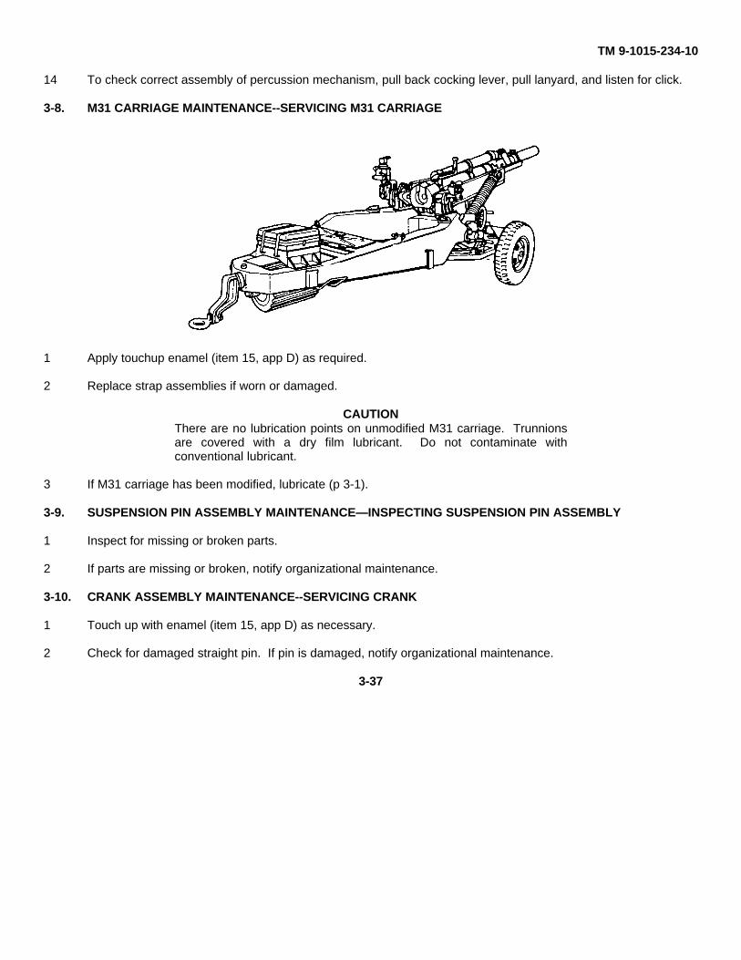
TM 9-1015-234-10
14 To check correct assembly of percussion mechanism, pull back cocking lever, pull lanyard, and listen for click.
3-8. M31 CARRIAGE MAINTENANCE--SERVICING M31 CARRIAGE
1 Apply touchup enamel (item 15, app D) as required.
2 Replace strap assemblies if worn or damaged.
CAUTIONThere are no lubrication points on unmodified M31 carriage. Trunnionsare covered with a dry film lubricant. Do not contaminate withconventional lubricant.
3 If M31 carriage has been modified, lubricate (p 3-1).
3-9. SUSPENSION PIN ASSEMBLY MAINTENANCE—INSPECTING SUSPENSION PIN ASSEMBLY
1 Inspect for missing or broken parts.
2 If parts are missing or broken, notify organizational maintenance.
3-10. CRANK ASSEMBLY MAINTENANCE--SERVICING CRANK
1 Touch up with enamel (item 15, app D) as necessary.
2 Check for damaged straight pin. If pin is damaged, notify organizational maintenance.
3-37
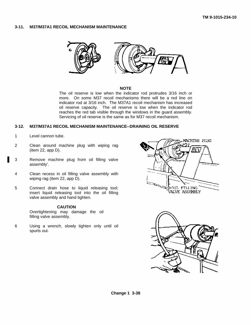
TM 9-1015-234-10
3-11. M37/M37A1 RECOIL MECHANISM MAINTENANCE
NOTEThe oil reserve is low when the indicator rod protrudes 3/16 inch ormore. On some M37 recoil mechanisms there will be a red line onindicator rod at 3/16 inch. The M37A1 recoil mechanism has increasedoil reserve capacity. The oil reserve is low when the indicator rodreaches the red tab visible through the windows in the guard assembly.Servicing of oil reserve is the same as for M37 recoil mechanism.
3-12. M37/M37A1 RECOIL MECHANISM MAINTENANCE--DRAINING OIL RESERVE
1 Level cannon tube.
2 Clean around machine plug with wiping rag(item 22, app D).
3 Remove machine plug from oil filling valveassembly'.
4 Clean recess in oil filling valve assembly withwiping rag (item 22, app D).
5 Connect drain hose to liquid releasing tool;insert liquid releasing tool into the oil fillingvalve assembly and hand tighten.
CAUTIONOvertightening may damage the oilfilling valve assembly.
6 Using a wrench, slowly tighten only until oilspurts out.
Change 1 3-38
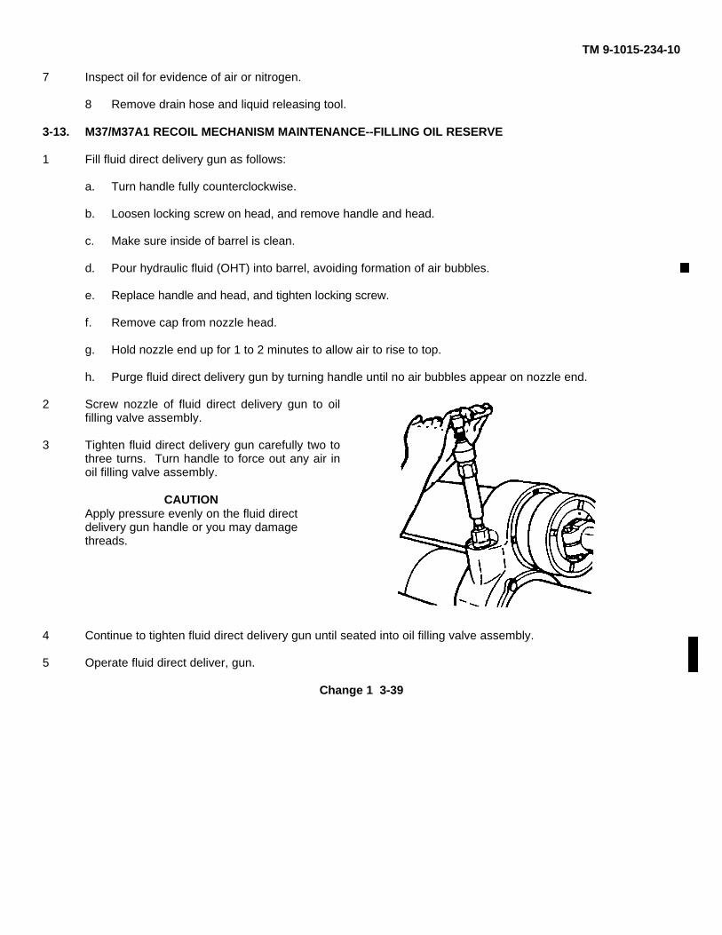
TM 9-1015-234-10
7 Inspect oil for evidence of air or nitrogen.
8 Remove drain hose and liquid releasing tool.
3-13. M37/M37A1 RECOIL MECHANISM MAINTENANCE--FILLING OIL RESERVE
1 Fill fluid direct delivery gun as follows:
a. Turn handle fully counterclockwise.
b. Loosen locking screw on head, and remove handle and head.
c. Make sure inside of barrel is clean.
d. Pour hydraulic fluid (OHT) into barrel, avoiding formation of air bubbles.
e. Replace handle and head, and tighten locking screw.
f. Remove cap from nozzle head.
g. Hold nozzle end up for 1 to 2 minutes to allow air to rise to top.
h. Purge fluid direct delivery gun by turning handle until no air bubbles appear on nozzle end.
2 Screw nozzle of fluid direct delivery gun to oilfilling valve assembly.
3 Tighten fluid direct delivery gun carefully two tothree turns. Turn handle to force out any air inoil filling valve assembly.
CAUTIONApply pressure evenly on the fluid directdelivery gun handle or you may damagethreads.
4 Continue to tighten fluid direct delivery gun until seated into oil filling valve assembly.
5 Operate fluid direct deliver, gun.
Change 1 3-39
TM 9-1015-234-10
3-13. M37/M37A1 RECOIL MECHANISM MAINTENANCE--FILLING OIL RESERVE (cont)
6 Fill M37 recoil mechanism until indicator rod is even with face of indicator and control assembly. FillM37A1recoil mechanism until indicator rod is even with indicator cap. Remove fluid direct delivery gun, clear oilfilling valve assembly and machine plug with wiping rag (item 22, app D), and install machine plug.
NOTEIf oil reserve is very low, or has been emptied, it may be necessary torepeat the filling process. If more than two fills from the fluid directdelivery gun are required, notify organizational maintenance.
3-14. M1A1 COLLIMATOR MAINTENANCE
WARNING
For M1A1 collimators, modified with the radioactive light source, if nolight is present in a low light atmosphere or the lens is broken, observeradiation warning found in the front of this manual.
CAUTION
The collimator Is hermetically sealed. Breaking the seal by removingany part (with exception of the lamp housing) will expose the internalmechanism to moisture, and may eventually impair operation ofinstrument.
3-15. M1A1 COLUMATOR MAINTENANCE--INSPECTING M1A1 COLLIMATOR
Check for illumination. If no light is present, notify RPO.
3-16. DELETED
Change 2 3-40
TM 9-1015-234-10
Section IV. MAINTENANCE OF AUXILIARY EQUIPMENT
3-17. DELETED
3-18. TAIL LIGHT ASSEMBLY MAINTENANCE
1 Clean with wiping rag (item 22, app D) as necessary.
2 If parts are damaged, notify organizational maintenance.
Section V. FIRE CONTROL ALINEMENT TESTS AND MEASUREMENTS
3-19. GENERAL
Fire control alinement tests are performed by the section crew members under the supervision of the battery executiveofficer, chief of firing battery, and artillery mechanic. These tests are performed at the discretion of the unit commander.Suggested times for these tests are as follows:
a. Once each year if the howitzer is used for nonfiring training.
b. Once every 3 months if the howitzer is fired.
c. As soon as possible after extensive use.
d. Following accidents.
e. Traversing extremely rough terrain.
f. When M134A1 mount or M14A1 quadrant has been replaced.
g. Whenever the howitzer fires inaccurately for no readily apparent reason.
h. When gun tube has been replaced.
Change 2 3-41
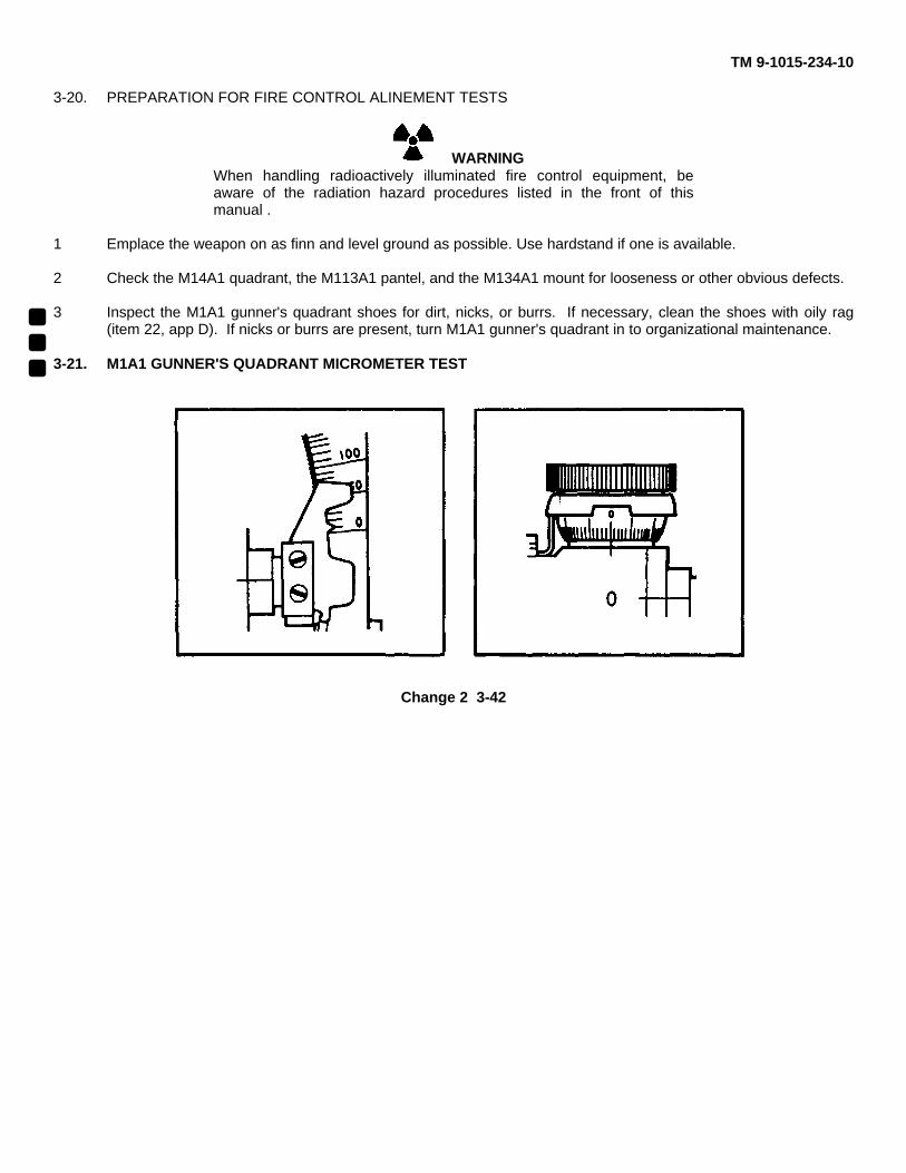
TM 9-1015-234-10
3-20. PREPARATION FOR FIRE CONTROL ALINEMENT TESTS
WARNINGWhen handling radioactively illuminated fire control equipment, beaware of the radiation hazard procedures listed in the front of thismanual .
1 Emplace the weapon on as finn and level ground as possible. Use hardstand if one is available.
2 Check the M14A1 quadrant, the M113A1 pantel, and the M134A1 mount for looseness or other obvious defects.
3 Inspect the M1A1 gunner's quadrant shoes for dirt, nicks, or burrs. If necessary, clean the shoes with oily rag(item 22, app D). If nicks or burrs are present, turn M1A1 gunner's quadrant in to organizational maintenance.
3-21. M1A1 GUNNER'S QUADRANT MICROMETER TEST
Change 2 3-42
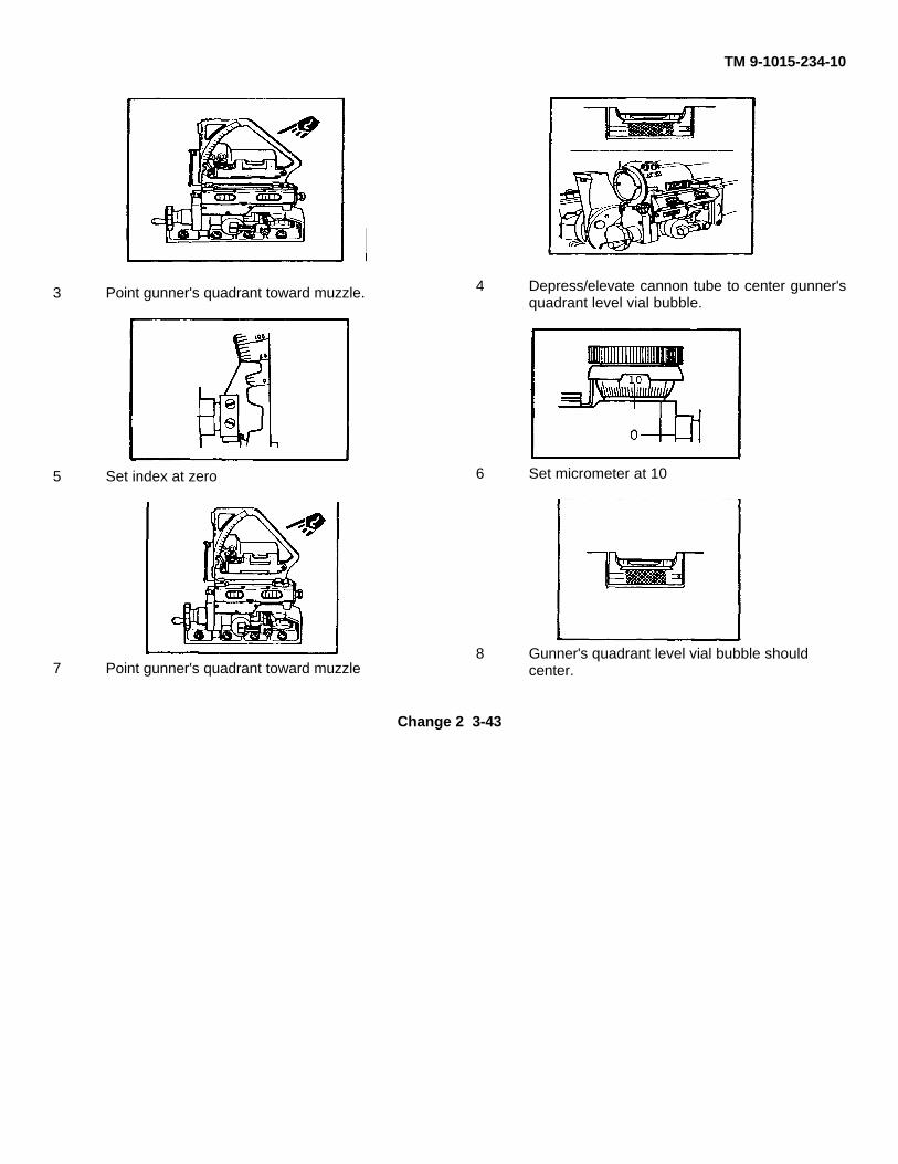
TM 9-1015-234-10
3 Point gunner's quadrant toward muzzle.
5 Set index at zero
7 Point gunner's quadrant toward muzzle
4 Depress/elevate cannon tube to center gunner'squadrant level vial bubble.
6 Set micrometer at 10
8 Gunner's quadrant level vial bubble shouldcenter.
Change 2 3-43
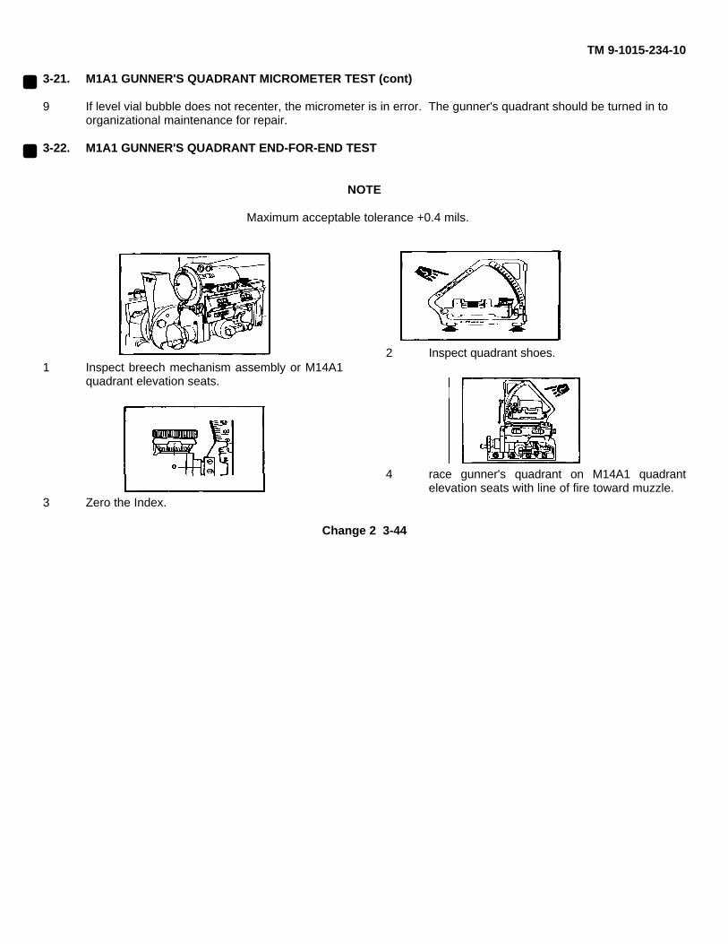
TM 9-1015-234-10
3-21. M1A1 GUNNER'S QUADRANT MICROMETER TEST (cont)
9 If level vial bubble does not recenter, the micrometer is in error. The gunner's quadrant should be turned in toorganizational maintenance for repair.
3-22. M1A1 GUNNER'S QUADRANT END-FOR-END TEST
NOTE
Maximum acceptable tolerance +0.4 mils.
1 Inspect breech mechanism assembly or M14A1quadrant elevation seats.
3 Zero the Index.
2 Inspect quadrant shoes.
4 race gunner's quadrant on M14A1 quadrantelevation seats with line of fire toward muzzle.
Change 2 3-44
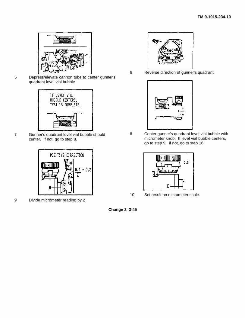
TM 9-1015-234-10
5 Depress/elevate cannon tube to center gunner'squadrant level vial bubble
7 Gunner's quadrant level vial bubble shouldcenter. If not, go to step 8.
9 Divide micrometer reading by 2
6 Reverse direction of gunner's quadrant
8 Center gunner's quadrant level vial bubble withmicrometer knob. If level vial bubble centers,go to step 9. If not, go to step 16.
10 Set result on micrometer scale.
Change 2 3-45
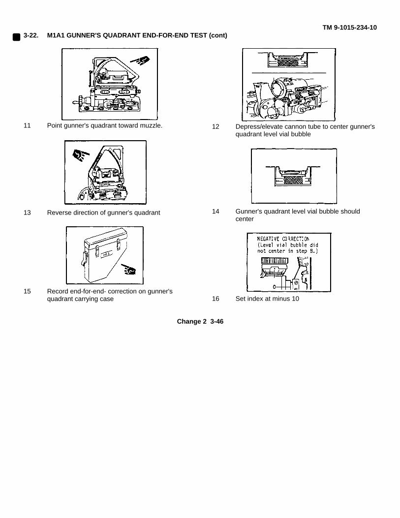
TM 9-1015-234-103-22. M1A1 GUNNER'S QUADRANT END-FOR-END TEST (cont)
11 Point gunner's quadrant toward muzzle.
13 Reverse direction of gunner's quadrant
15 Record end-for-end- correction on gunner'squadrant carrying case
12 Depress/elevate cannon tube to center gunner'squadrant level vial bubble
14 Gunner's quadrant level vial bubble shouldcenter
16 Set index at minus 10
Change 2 3-46
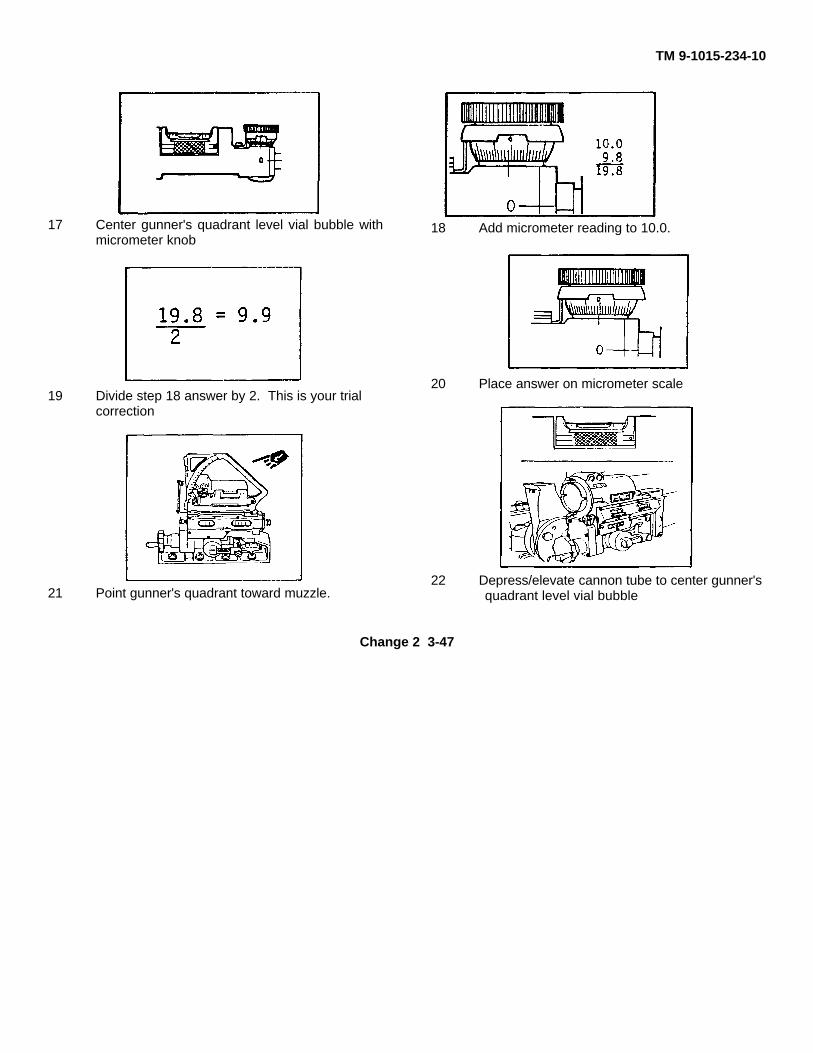
TM 9-1015-234-10
17 Center gunner's quadrant level vial bubble withmicrometer knob
19 Divide step 18 answer by 2. This is your trialcorrection
21 Point gunner's quadrant toward muzzle.
18 Add micrometer reading to 10.0.
20 Place answer on micrometer scale
22 Depress/elevate cannon tube to center gunner'squadrant level vial bubble
Change 2 3-47
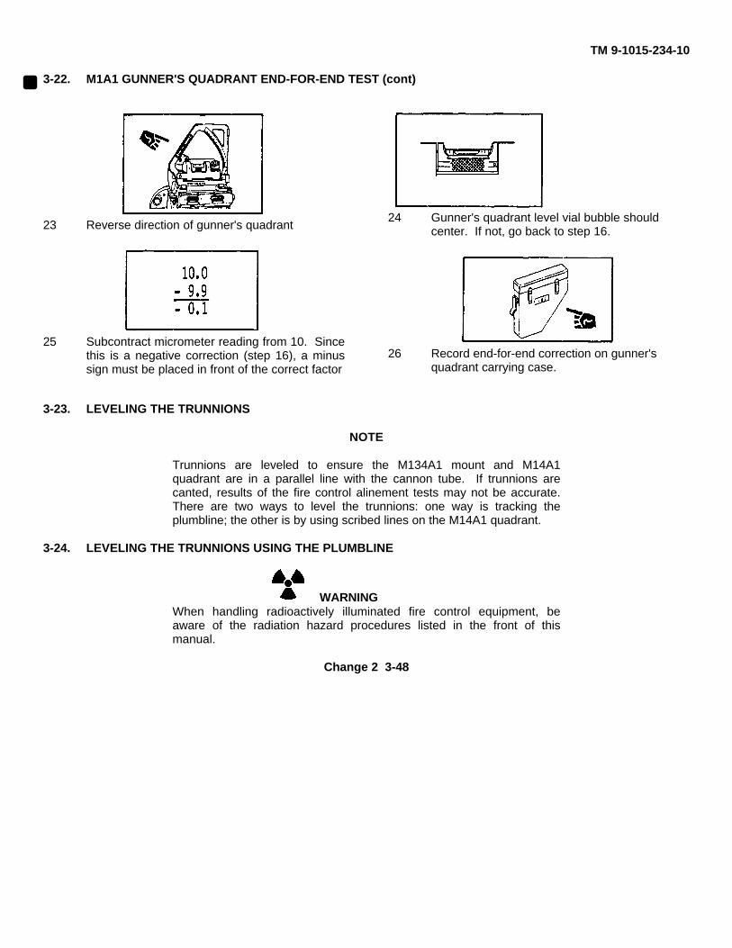
TM 9-1015-234-10
3-22. M1A1 GUNNER'S QUADRANT END-FOR-END TEST (cont)
23 Reverse direction of gunner's quadrant
25 Subcontract micrometer reading from 10. Sincethis is a negative correction (step 16), a minussign must be placed in front of the correct factor
24 Gunner's quadrant level vial bubble shouldcenter. If not, go back to step 16.
26 Record end-for-end correction on gunner'squadrant carrying case.
3-23. LEVELING THE TRUNNIONS
NOTE
Trunnions are leveled to ensure the M134A1 mount and M14A1quadrant are in a parallel line with the cannon tube. If trunnions arecanted, results of the fire control alinement tests may not be accurate.There are two ways to level the trunnions: one way is tracking theplumbline; the other is by using scribed lines on the M14A1 quadrant.
3-24. LEVELING THE TRUNNIONS USING THE PLUMBLINE
WARNINGWhen handling radioactively illuminated fire control equipment, beaware of the radiation hazard procedures listed in the front of thismanual.
Change 2 3-48
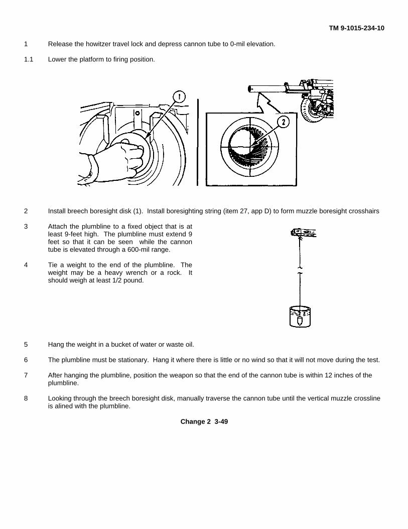
TM 9-1015-234-10
1 Release the howitzer travel lock and depress cannon tube to 0-mil elevation.
1.1 Lower the platform to firing position.
2 Install breech boresight disk (1). Install boresighting string (item 27, app D) to form muzzle boresight crosshairs
3 Attach the plumbline to a fixed object that is atleast 9-feet high. The plumbline must extend 9feet so that it can be seen while the cannontube is elevated through a 600-mil range.
4 Tie a weight to the end of the plumbline. Theweight may be a heavy wrench or a rock. Itshould weigh at least 1/2 pound.
5 Hang the weight in a bucket of water or waste oil.
6 The plumbline must be stationary. Hang it where there is little or no wind so that it will not move during the test.
7 After hanging the plumbline, position the weapon so that the end of the cannon tube is within 12 inches of theplumbline.
8 Looking through the breech boresight disk, manually traverse the cannon tube until the vertical muzzle crosslineis alined with the plumbline.
Change 2 3-49
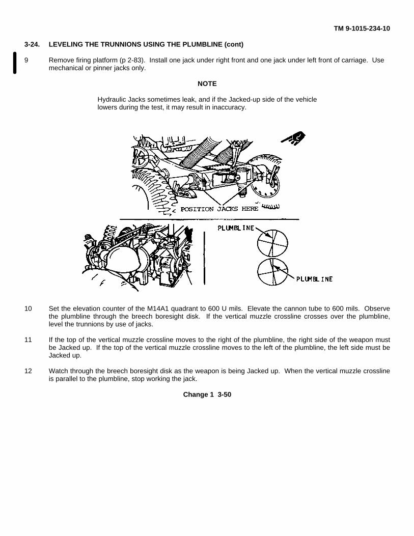
TM 9-1015-234-10
3-24. LEVELING THE TRUNNIONS USING THE PLUMBLINE (cont)
9 Remove firing platform (p 2-83). Install one jack under right front and one jack under left front of carriage. Usemechanical or pinner jacks only.
NOTE
Hydraulic Jacks sometimes leak, and if the Jacked-up side of the vehiclelowers during the test, it may result in inaccuracy.
10 Set the elevation counter of the M14A1 quadrant to 600 U mils. Elevate the cannon tube to 600 mils. Observethe plumbline through the breech boresight disk. If the vertical muzzle crossline crosses over the plumbline,level the trunnions by use of jacks.
11 If the top of the vertical muzzle crossline moves to the right of the plumbline, the right side of the weapon mustbe Jacked up. If the top of the vertical muzzle crossline moves to the left of the plumbline, the left side must beJacked up.
12 Watch through the breech boresight disk as the weapon is being Jacked up. When the vertical muzzle crosslineis parallel to the plumbline, stop working the jack.
Change 1 3-50

TM 9-1015-234-10
13 Set the elevation counter of the M14A1 quadrant on zero and depress the cannon tube to 0 mil. Traverse thecannon tube until the vertical muzzle crossline is back on the plumb- line.
14 Elevate and depress the cannon tube to ensure that the vertical muzzle crossline remains parallel and directly inline with the plumbline, from O-mil to 600-mil elevation. It may be necessary to repeat steps 11 thru 14.
15 When the vertical muzzle crossline tracks in line with the plumbline from O-mil to 600-mil elevation, thetrunnions are level.
Change 1 3-50.1 (3-50.2 blank)
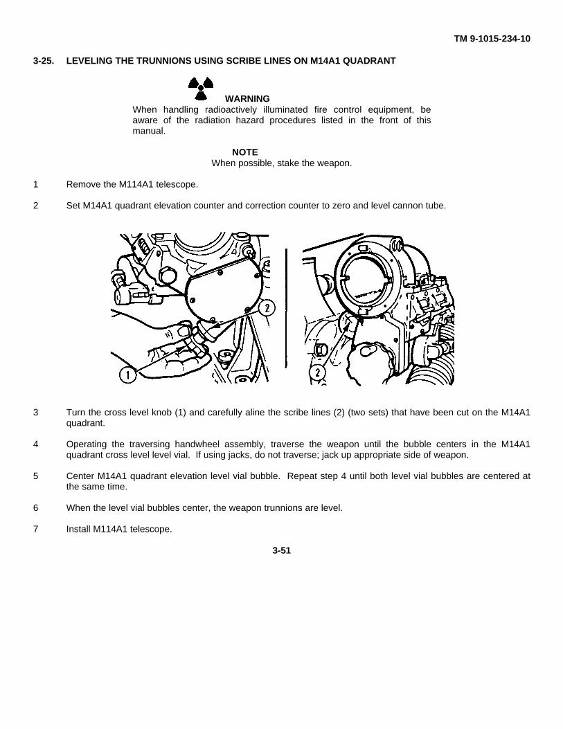
TM 9-1015-234-10
3-25. LEVELING THE TRUNNIONS USING SCRIBE LINES ON M14A1 QUADRANT
WARNINGWhen handling radioactively illuminated fire control equipment, beaware of the radiation hazard procedures listed in the front of thismanual.
NOTEWhen possible, stake the weapon.
1 Remove the M114A1 telescope.
2 Set M14A1 quadrant elevation counter and correction counter to zero and level cannon tube.
3 Turn the cross level knob (1) and carefully aline the scribe lines (2) (two sets) that have been cut on the M14A1quadrant.
4 Operating the traversing handwheel assembly, traverse the weapon until the bubble centers in the M14A1quadrant cross level level vial. If using jacks, do not traverse; jack up appropriate side of weapon.
5 Center M14A1 quadrant elevation level vial bubble. Repeat step 4 until both level vial bubbles are centered atthe same time.
6 When the level vial bubbles center, the weapon trunnions are level.
7 Install M114A1 telescope.
3-51
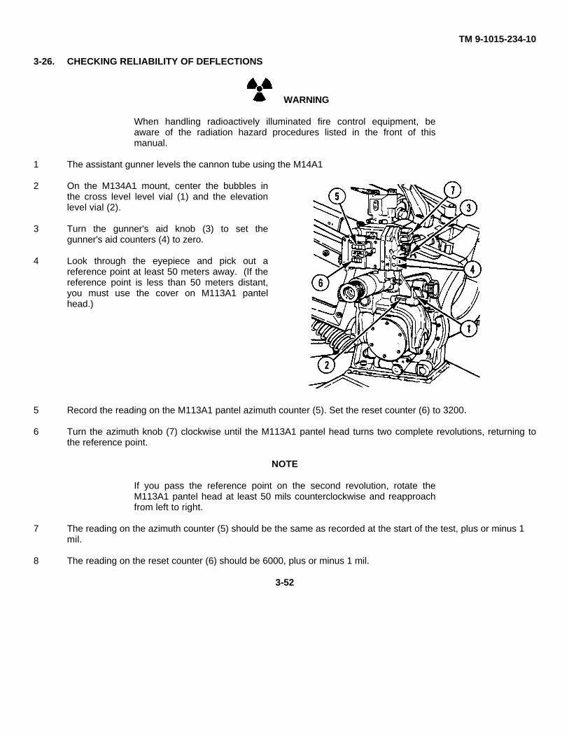
TM 9-1015-234-10
3-26. CHECKING RELIABILITY OF DEFLECTIONS
WARNING
When handling radioactively illuminated fire control equipment, beaware of the radiation hazard procedures listed in the front of thismanual.
1 The assistant gunner levels the cannon tube using the M14A1
2 On the M134A1 mount, center the bubbles inthe cross level level vial (1) and the elevationlevel vial (2).
3 Turn the gunner's aid knob (3) to set thegunner's aid counters (4) to zero.
4 Look through the eyepiece and pick out areference point at least 50 meters away. (If thereference point is less than 50 meters distant,you must use the cover on M113A1 pantelhead.)
5 Record the reading on the M113A1 pantel azimuth counter (5). Set the reset counter (6) to 3200.
6 Turn the azimuth knob (7) clockwise until the M113A1 pantel head turns two complete revolutions, returning tothe reference point.
NOTE
If you pass the reference point on the second revolution, rotate theM113A1 pantel head at least 50 mils counterclockwise and reapproachfrom left to right.
7 The reading on the azimuth counter (5) should be the same as recorded at the start of the test, plus or minus 1mil.
8 The reading on the reset counter (6) should be 6000, plus or minus 1 mil.
3-52
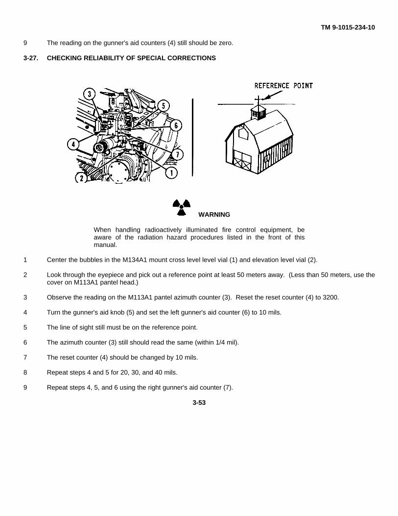
TM 9-1015-234-10
9 The reading on the gunner's aid counters (4) still should be zero.
3-27. CHECKING RELIABILITY OF SPECIAL CORRECTIONS
WARNING
When handling radioactively illuminated fire control equipment, beaware of the radiation hazard procedures listed in the front of thismanual.
1 Center the bubbles in the M134A1 mount cross level level vial (1) and elevation level vial (2).
2 Look through the eyepiece and pick out a reference point at least 50 meters away. (Less than 50 meters, use thecover on M113A1 pantel head.)
3 Observe the reading on the M113A1 pantel azimuth counter (3). Reset the reset counter (4) to 3200.
4 Turn the gunner's aid knob (5) and set the left gunner's aid counter (6) to 10 mils.
5 The line of sight still must be on the reference point.
6 The azimuth counter (3) still should read the same (within 1/4 mil).
7 The reset counter (4) should be changed by 10 mils.
8 Repeat steps 4 and 5 for 20, 30, and 40 mils.
9 Repeat steps 4, 5, and 6 using the right gunner's aid counter (7).
3-53
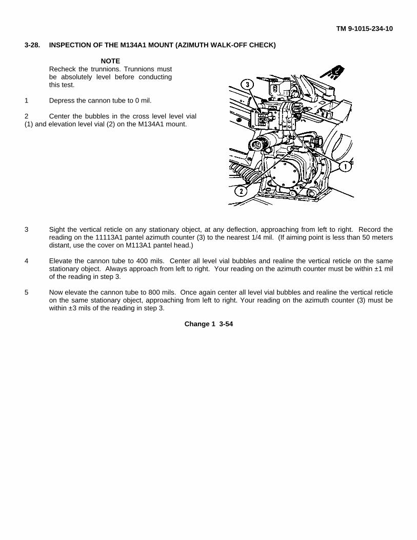
TM 9-1015-234-10
3-28. INSPECTION OF THE M134A1 MOUNT (AZIMUTH WALK-OFF CHECK)
NOTERecheck the trunnions. Trunnions mustbe absolutely level before conductingthis test.
1 Depress the cannon tube to 0 mil.
2 Center the bubbles in the cross level level vial(1) and elevation level vial (2) on the M134A1 mount.
3 Sight the vertical reticle on any stationary object, at any deflection, approaching from left to right. Record thereading on the 11113A1 pantel azimuth counter (3) to the nearest 1/4 mil. (If aiming point is less than 50 metersdistant, use the cover on M113A1 pantel head.)
4 Elevate the cannon tube to 400 mils. Center all level vial bubbles and realine the vertical reticle on the samestationary object. Always approach from left to right. Your reading on the azimuth counter must be within ±1 milof the reading in step 3.
5 Now elevate the cannon tube to 800 mils. Once again center all level vial bubbles and realine the vertical reticleon the same stationary object, approaching from left to right. Your reading on the azimuth counter (3) must bewithin ±3 mils of the reading in step 3.
Change 1 3-54
TM 9-1015-234-10
3-29. LEVELING THE CANNON TUBE
WARNING
When handling radioactively illuminated fire control equipment, beaware of the radiation hazard procedures listed in the front of thismanual.
NOTE
The new manufacture cannon has quadrant seats on the top muzzle endof the cannon tube. Be sure trunnions are level before you level thecannon tube. For the M14A1 quadrant test (p 3-57), you must level thecannon tube as accurately as possible. There are two ways toaccomplish this: using the cannon tube quadrant seats or using the guntube leveling fixture.
Change 1 3-54.1 (3-54.2 blank)
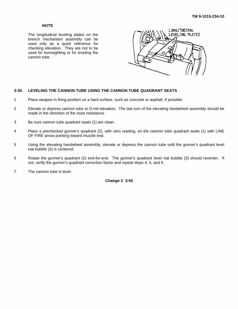
TM 9-1015-234-10
NOTE
The longitudinal leveling plates on thebreech mechanism assembly can beused only as a quick reference forchecking elevation. They are not to beused for boresighting or for leveling thecannon tube.
3-30. LEVELING THE CANNON TUBE USING THE CANNON TUBE QUADRANT SEATS
1 Place weapon in firing position on a hard surface, such as concrete or asphalt, if possible.
2 Elevate or depress cannon tube to O-mil elevation. The last turn of the elevating handwheel assembly should bemade in the direction of the most resistance.
3 Be sure cannon tube quadrant seats (1) are clean.
4 Place a prechecked gunner's quadrant (2), with zero reading, on the cannon tube quadrant seats (1) with LINEOF FIRE arrow pointing toward muzzle end.
5 Using the elevating handwheel assembly, elevate or depress the cannon tube until the gunner's quadrant levelvial bubble (3) is centered.
6 Rotate the gunner's quadrant (2) end-for-end. The gunner's quadrant level vial bubble (3) should recenter. Ifnot, verify the gunner's quadrant correction factor and repeat steps 4, 5, and 6.
7 The cannon tube is level.
Change 2 3-55
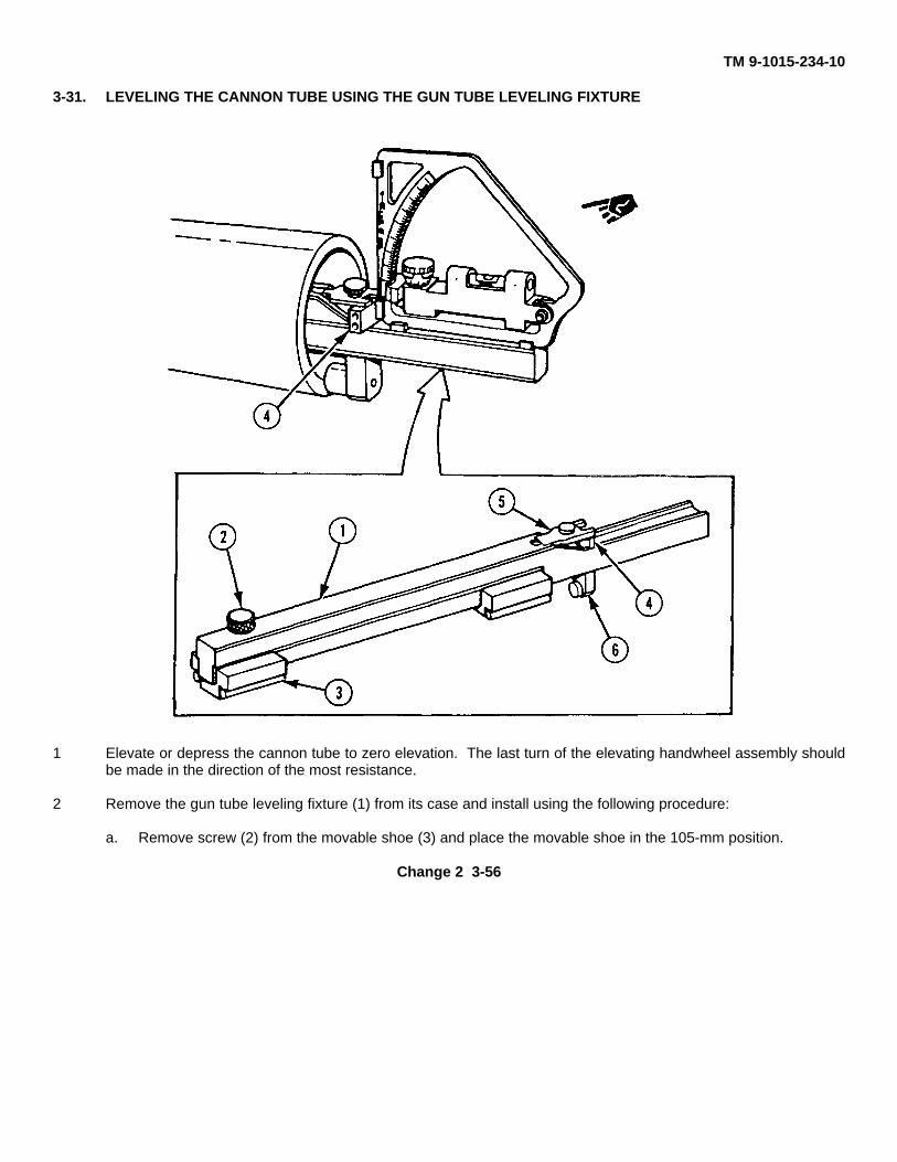
TM 9-1015-234-10
3-31. LEVELING THE CANNON TUBE USING THE GUN TUBE LEVELING FIXTURE
1 Elevate or depress the cannon tube to zero elevation. The last turn of the elevating handwheel assembly shouldbe made in the direction of the most resistance.
2 Remove the gun tube leveling fixture (1) from its case and install using the following procedure:
a. Remove screw (2) from the movable shoe (3) and place the movable shoe in the 105-mm position.
Change 2 3-56
TM 9-1015-234-10
b. Replace screw in the proper hole and tighten securely.
c. Insert cross level vial (4) under the holder (5) on the gun tube leveling fixture. Place the stop assembly (6)on the screw protruding through the gun tube leveling fixture from the holder (5). Tighten securely.
d. Insert the gun tube leveling fixture into the muzzle end of the cannon tube until contact is made between thestop assembly and face of the cannon tube. Ensure magnet portion of stop assembly is flush with thecannon tube.
e. Rotate gun tube leveling fixture until the bubble is centered in the cross level vial (4).
3 Place a prechecked gunner's quadrant, with zero reading, in the groove of the gun tube leveling fixture. Applythe correction factor, if applicable.
4 Turn the elevation handwheel assembly in the direction of greatest resistance to elevate or depress the cannontube until the gunner's quadrant level vial bubble is centered.
5 Rotate the gunner's quadrant. The level vial bubble should recenter.
6 The cannon tube is level.
3-32. M14A1 QUADRANT TEST
WARNINGWhen handling radioactively illuminated fire control equipment, beaware of the radiation hazard procedures listed in the front of thismanual.
CAUTIONDo not move the level cannon tube until the beginning of step 8.
NOTEBe sure trunnions and cannon tube are level before performing this test,using the cannon tube quadrant seats or the gun tube leveling fixtureprocedures.
3-57
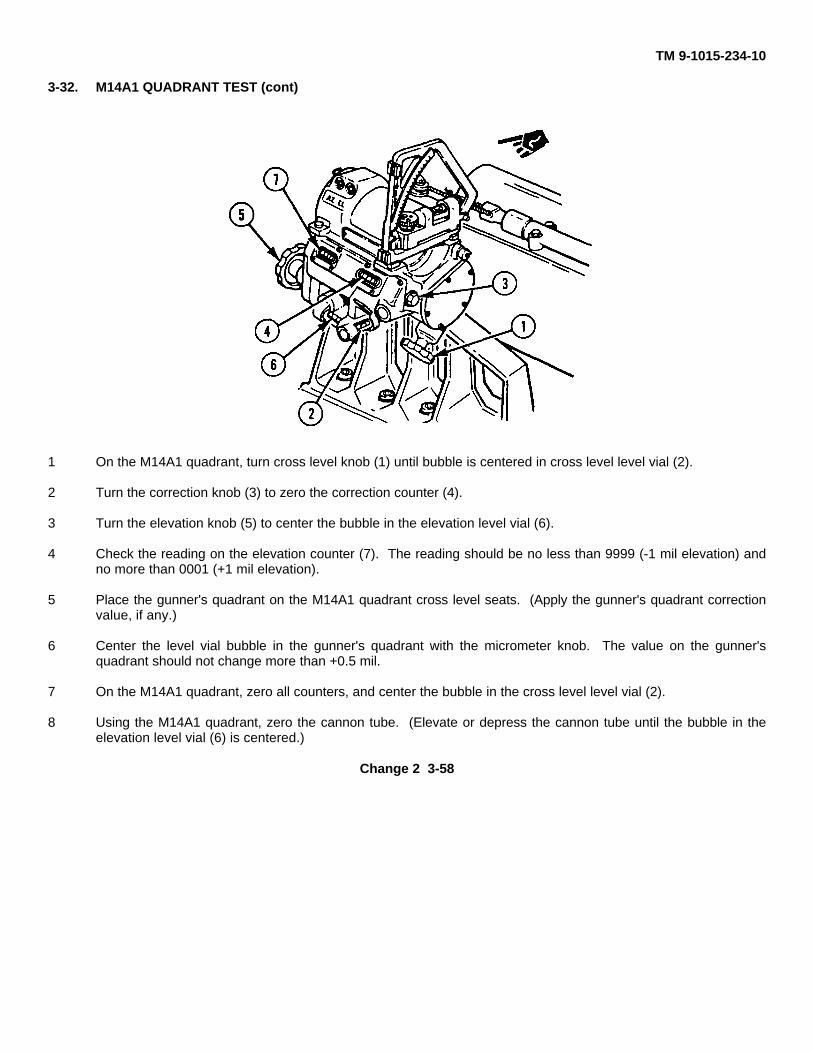
TM 9-1015-234-10
3-32. M14A1 QUADRANT TEST (cont)
1 On the M14A1 quadrant, turn cross level knob (1) until bubble is centered in cross level level vial (2).
2 Turn the correction knob (3) to zero the correction counter (4).
3 Turn the elevation knob (5) to center the bubble in the elevation level vial (6).
4 Check the reading on the elevation counter (7). The reading should be no less than 9999 (-1 mil elevation) andno more than 0001 (+1 mil elevation).
5 Place the gunner's quadrant on the M14A1 quadrant cross level seats. (Apply the gunner's quadrant correctionvalue, if any.)
6 Center the level vial bubble in the gunner's quadrant with the micrometer knob. The value on the gunner'squadrant should not change more than +0.5 mil.
7 On the M14A1 quadrant, zero all counters, and center the bubble in the cross level level vial (2).
8 Using the M14A1 quadrant, zero the cannon tube. (Elevate or depress the cannon tube until the bubble in theelevation level vial (6) is centered.)
Change 2 3-58
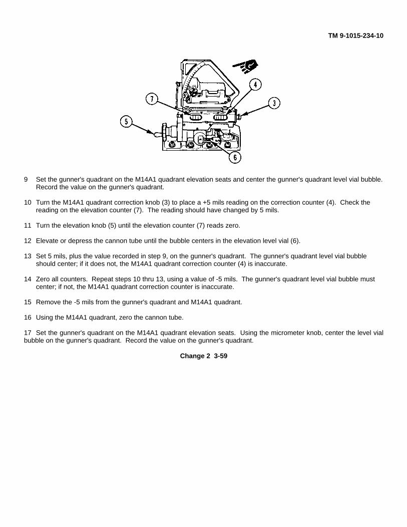
TM 9-1015-234-10
9 Set the gunner's quadrant on the M14A1 quadrant elevation seats and center the gunner's quadrant level vial bubble.Record the value on the gunner's quadrant.
10 Turn the M14A1 quadrant correction knob (3) to place a +5 mils reading on the correction counter (4). Check the reading on the elevation counter (7). The reading should have changed by 5 mils.
11 Turn the elevation knob (5) until the elevation counter (7) reads zero.
12 Elevate or depress the cannon tube until the bubble centers in the elevation level vial (6).
13 Set 5 mils, plus the value recorded in step 9, on the gunner's quadrant. The gunner's quadrant level vial bubble should center; if it does not, the M14A1 quadrant correction counter (4) is inaccurate.
14 Zero all counters. Repeat steps 10 thru 13, using a value of -5 mils. The gunner's quadrant level vial bubble must center; if not, the M14A1 quadrant correction counter is inaccurate.
15 Remove the -5 mils from the gunner's quadrant and M14A1 quadrant.
16 Using the M14A1 quadrant, zero the cannon tube.
17 Set the gunner's quadrant on the M14A1 quadrant elevation seats. Using the micrometer knob, center the level vialbubble on the gunner's quadrant. Record the value on the gunner's quadrant.
Change 2 3-59
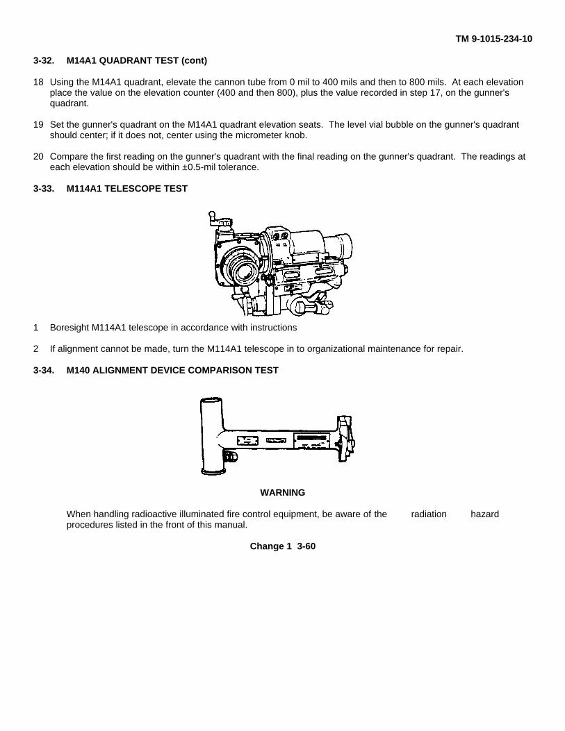
TM 9-1015-234-10
3-32. M14A1 QUADRANT TEST (cont)
18 Using the M14A1 quadrant, elevate the cannon tube from 0 mil to 400 mils and then to 800 mils. At each elevation place the value on the elevation counter (400 and then 800), plus the value recorded in step 17, on the gunner's quadrant.
19 Set the gunner's quadrant on the M14A1 quadrant elevation seats. The level vial bubble on the gunner's quadrant should center; if it does not, center using the micrometer knob.
20 Compare the first reading on the gunner's quadrant with the final reading on the gunner's quadrant. The readings at each elevation should be within ±0.5-mil tolerance.
3-33. M114A1 TELESCOPE TEST
1 Boresight M114A1 telescope in accordance with instructions
2 If alignment cannot be made, turn the M114A1 telescope in to organizational maintenance for repair.
3-34. M140 ALIGNMENT DEVICE COMPARISON TEST
WARNING
When handling radioactive illuminated fire control equipment, be aware of the radiation hazardprocedures listed in the front of this manual.
Change 1 3-60
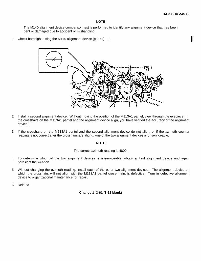
TM 9-1015-234-10
NOTE
The M140 alignment device comparison test is performed to identify any alignment device that has beenbent or damaged due to accident or mishandling.
1 Check boresight, using the M140 alignment device (p 2-44). 1
2 Install a second alignment device. Without moving the position of the M113A1 pantel, view through the eyepiece. Ifthe crosshairs on the M113A1 pantel and the alignment device align, you have verified the accuracy of the alignmentdevice.
3 If the crosshairs on the M113A1 pantel and the second alignment device do not align, or if the azimuth counterreading is not correct after the crosshairs are alignd, one of the two alignment devices is unserviceable.
NOTE
The correct azimuth reading is 4800.
4 To determine which of the two alignment devices is unserviceable, obtain a third alignment device and againboresight the weapon.
5 Without changing the azimuth reading, install each of the other two alignment devices. The alignment device onwhich the crosshairs will not align with the M113A1 pantel cross- hairs is defective. Turn in defective alignmentdevice to organizational maintenance for repair.
6 Deleted.
Change 1 3-61 (3-62 blank)
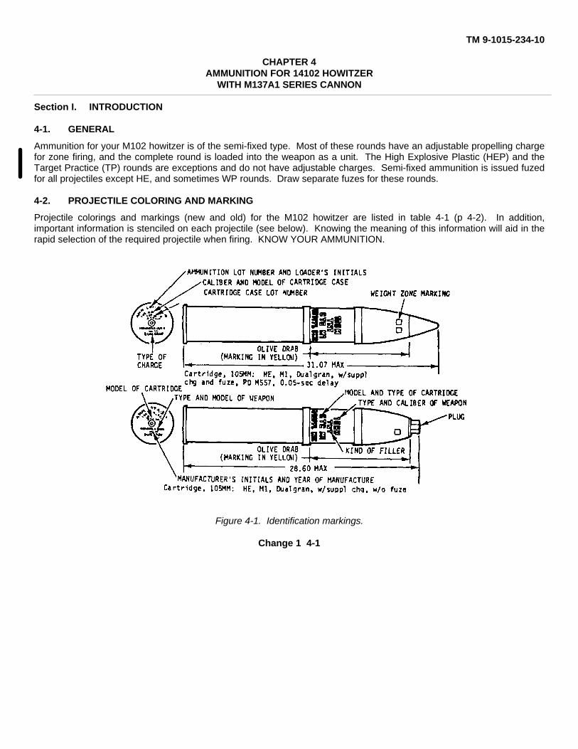
TM 9-1015-234-10
CHAPTER 4AMMUNITION FOR 14102 HOWITZER
WITH M137A1 SERIES CANNON
Section I. INTRODUCTION
4-1. GENERAL
Ammunition for your M102 howitzer is of the semi-fixed type. Most of these rounds have an adjustable propelling chargefor zone firing, and the complete round is loaded into the weapon as a unit. The High Explosive Plastic (HEP) and theTarget Practice (TP) rounds are exceptions and do not have adjustable charges. Semi-fixed ammunition is issued fuzedfor all projectiles except HE, and sometimes WP rounds. Draw separate fuzes for these rounds.
4-2. PROJECTILE COLORING AND MARKING
Projectile colorings and markings (new and old) for the M102 howitzer are listed in table 4-1 (p 4-2). In addition,important information is stenciled on each projectile (see below). Knowing the meaning of this information will aid in therapid selection of the required projectile when firing. KNOW YOUR AMMUNITION.
Figure 4-1. Identification markings.
Change 1 4-1

TM 9-1015-234-10
4-2. PROJECTILE COLORING AND MARKING (cont)
Table 4-1. Model Numbers and Color Coding of Projectilesfor M102 Howitzer
NEW MANUFACTURE OLD MANUFACTURE
Type and Color Colormodel of Number/ of Number/number pro- color pro- colorof jec- of Mark- jec- of Mark-projectile tile bands ing tile bands ing
White(whitedia-monds
APERS-T indi-XM546* cate
and Olive fle-M546* drab 1/yellow chettes) NA NA NA
Un-painted Black
Dummy, M14 or orbronze None White Blue None White
Gas (H, HD), 2/greenM60 Gray 1/yellow Green Gray 2/green Green
Gas (GB),w/burster, 3/greenM360 Gray 1/yellow Green Gray 2/green Green
Gas (GB),w/o burster,M360 Gray 3/green Green Gray 2/green Green
OliveM444 ICM drab None** Yellow NA NA NA
*The XM546 APERS (Beehive) round will not be fired over the heads of friendly troops. See table 4-4 for firingrestrictions.
*Indicates a row of yellow diamonds around the ogive of the projectile.
Change 2 4-2
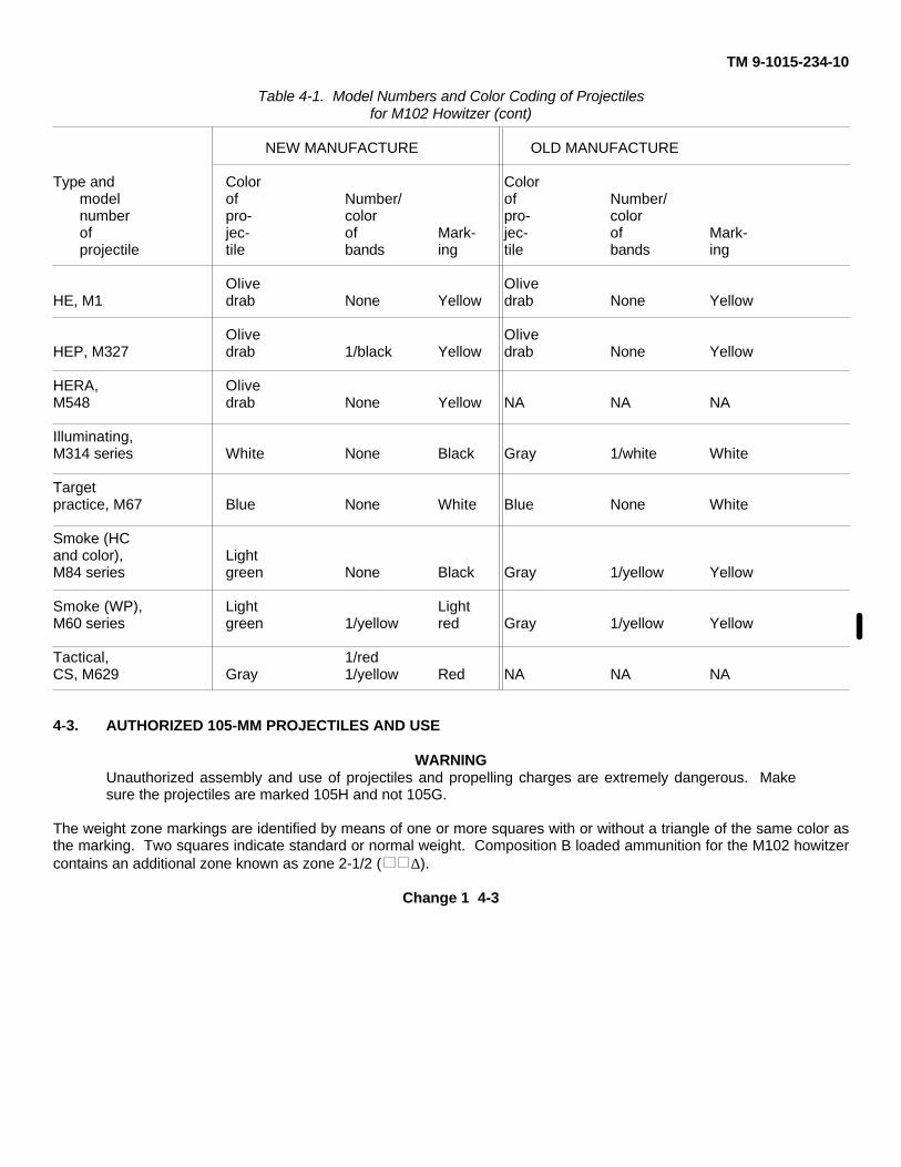
TM 9-1015-234-10
Table 4-1. Model Numbers and Color Coding of Projectilesfor M102 Howitzer (cont)
NEW MANUFACTURE OLD MANUFACTURE
Type and Color Colormodel of Number/ of Number/number pro- color pro- colorof jec- of Mark- jec- of Mark-projectile tile bands ing tile bands ing
Olive OliveHE, M1 drab None Yellow drab None Yellow
Olive OliveHEP, M327 drab 1/black Yellow drab None Yellow
HERA, OliveM548 drab None Yellow NA NA NA
Illuminating,M314 series White None Black Gray 1/white White
Targetpractice, M67 Blue None White Blue None White
Smoke (HCand color), LightM84 series green None Black Gray 1/yellow Yellow
Smoke (WP), Light LightM60 series green 1/yellow red Gray 1/yellow Yellow
Tactical, 1/redCS, M629 Gray 1/yellow Red NA NA NA
4-3. AUTHORIZED 105-MM PROJECTILES AND USE
WARNINGUnauthorized assembly and use of projectiles and propelling charges are extremely dangerous. Makesure the projectiles are marked 105H and not 105G.
The weight zone markings are identified by means of one or more squares with or without a triangle of the same color asthe marking. Two squares indicate standard or normal weight. Composition B loaded ammunition for the M102 howitzercontains an additional zone known as zone 2-1/2 ( ∆).
Change 1 4-3
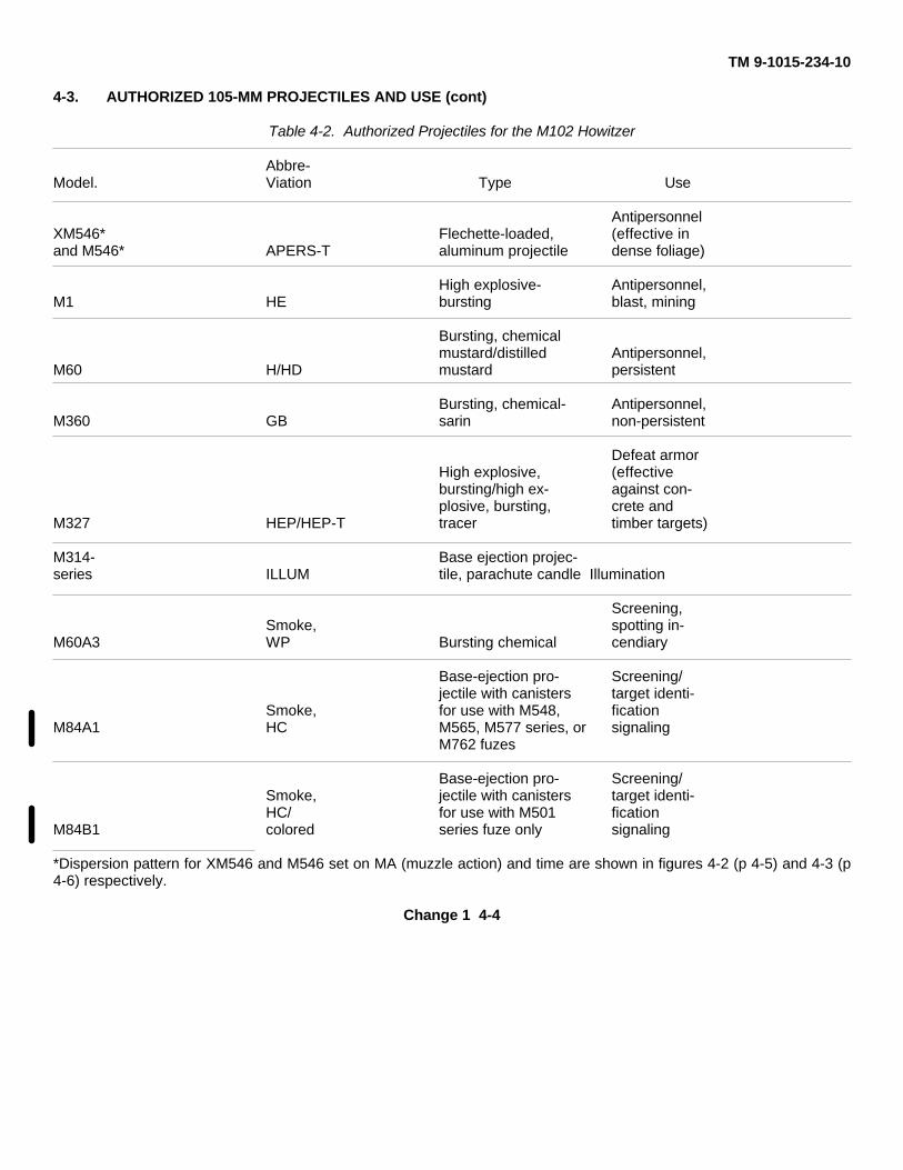
TM 9-1015-234-10
4-3. AUTHORIZED 105-MM PROJECTILES AND USE (cont)
Table 4-2. Authorized Projectiles for the M102 Howitzer
Abbre-Model. Viation Type Use
AntipersonnelXM546* Flechette-loaded, (effective inand M546* APERS-T aluminum projectile dense foliage)
High explosive- Antipersonnel,M1 HE bursting blast, mining
Bursting, chemicalmustard/distilled Antipersonnel,
M60 H/HD mustard persistent
Bursting, chemical- Antipersonnel,M360 GB sarin non-persistent
Defeat armorHigh explosive, (effectivebursting/high ex- against con-plosive, bursting, crete and
M327 HEP/HEP-T tracer timber targets)
M314- Base ejection projec-series ILLUM tile, parachute candle Illumination
Screening,Smoke, spotting in-
M60A3 WP Bursting chemical cendiary
Base-ejection pro- Screening/jectile with canisters target identi-
Smoke, for use with M548, ficationM84A1 HC M565, M577 series, or signaling
M762 fuzes
Base-ejection pro- Screening/Smoke, jectile with canisters target identi-HC/ for use with M501 fication
M84B1 colored series fuze only signaling
*Dispersion pattern for XM546 and M546 set on MA (muzzle action) and time are shown in figures 4-2 (p 4-5) and 4-3 (p4-6) respectively.
Change 1 4-4
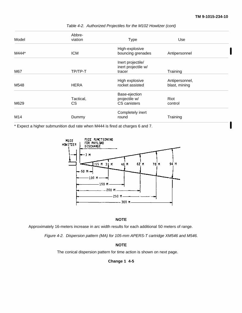
TM 9-1015-234-10
Table 4-2. Authorized Projectiles for the M102 Howitzer (cont)
Abbre-Model viation Type Use
High-explosiveM444* ICM bouncing grenades Antipersonnel
Inert projectile/inert projectile w/
M67 TP/TP-T tracer Training
High explosive Antipersonnel,M548 HERA rocket assisted blast, mining
Base-ejectionTactical, projectile w/ Riot
M629 CS CS canisters control
Completely inertM14 Dummy round Training
* Expect a higher submunition dud rate when M444 is fired at charges 6 and 7.
NOTE
Approximately 16-meters increase in arc width results for each additional 50 meters of range.
Figure 4-2. Dispersion pattern (MA) for 105-mm APERS-T cartridge XM546 and M546.
NOTE
The conical dispersion pattern for time action is shown on next page.
Change 1 4-5
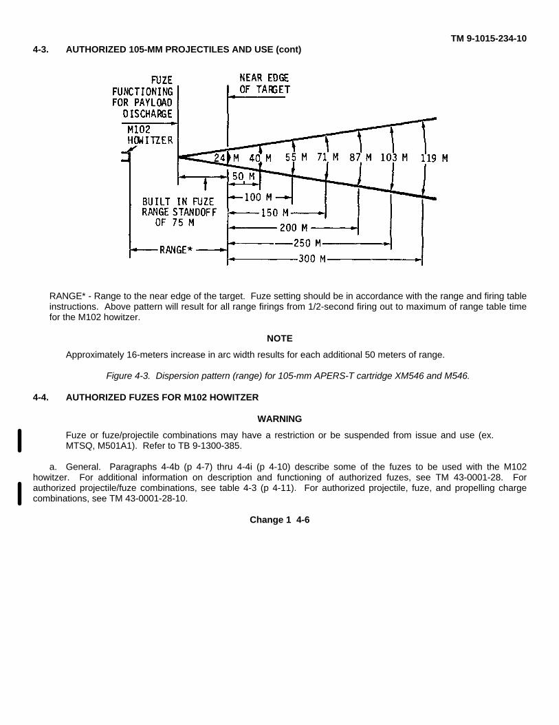
TM 9-1015-234-104-3. AUTHORIZED 105-MM PROJECTILES AND USE (cont)
RANGE* - Range to the near edge of the target. Fuze setting should be in accordance with the range and firing tableinstructions. Above pattern will result for all range firings from 1/2-second firing out to maximum of range table timefor the M102 howitzer.
NOTE
Approximately 16-meters increase in arc width results for each additional 50 meters of range.
Figure 4-3. Dispersion pattern (range) for 105-mm APERS-T cartridge XM546 and M546.
4-4. AUTHORIZED FUZES FOR M102 HOWITZER
WARNING
Fuze or fuze/projectile combinations may have a restriction or be suspended from issue and use (ex.MTSQ, M501A1). Refer to TB 9-1300-385.
a. General. Paragraphs 4-4b (p 4-7) thru 4-4i (p 4-10) describe some of the fuzes to be used with the M102howitzer. For additional information on description and functioning of authorized fuzes, see TM 43-0001-28. Forauthorized projectile/fuze combinations, see table 4-3 (p 4-11). For authorized projectile, fuze, and propelling chargecombinations, see TM 43-0001-28-10.
Change 1 4-6
TM 9-1015-234-10
POINT DETONATING CONCRETE PIERCING FUZE M78A1 AND BOOSTER M25
b. Fuze, Point Detonating, Concrete Piercing: M78A1 Series. The M78A1 series fuzes are constructed primarily foruse against concrete targets. M78A1 fuzes are of two types--a non-delay type used for spotting purposes and a delaytype for concrete targets. The non-delay type has its nose painted white for identification. If these fuzes are used with adeep cavity shell the supplementary charge must remain in the fuze well cavity.
POINT DETONATING FUZE M557 AND M572
c. Fuze, Point Detonating: M557 and M572. The M557 fuze has a selective superquick-delay setscrew. It ispacked set for superquick and has a booster attached. The M572 is identical to the M557, with the exception of epoxyfiller under the steel ogive, and is handled, set, and fired the same as the M557. Premature functioning can occur whenthese fuzes are fired in heavy precipitation; i.e., rainfall, sleet, snow, or hail. These fuzes can be set for superquick ordelay action by turning the setscrew.
Change 2 4-7
TM 9-1015-234-104-4. AUTHORIZED FUZES FOR M102 HOWITZER (cont)
POINT DETONATING FUZE M739
d. Fuze, Point Detonating: M739 Series. The M739 series fuzes are the latest improved version of the selectiveimpact fuze. These fuzes have an aluminum-filled body and a rain-in- sensitive head so that they can be fired throughheavy precipitation without premature functioning. These fuzes can be set for superquick or delay action by turning thesetscrew. The M739A1 fuze contains an improved impact delay module which provides rmore effective functioning inthe delay mode. In addition to the stamped marking, the M739A1 fuze body is anodized green for positive identificationof fuze model.
MECHANICAL TIME AND SUPERQUICK FUZE M564
WARINGFuze or fuze/projectile combinations may have a restriction or be suspended from issue and use (ex.MTSQ, M501A1). Refer to TB 9-1300-385.
Change 1 4-8
TM 9-1015-234-10
e. Fuze, Mechanical Time and Superquick: M564. The M564 fuze is an improvement over the older MTSQ fuzes,in that it provides a longer timing mechanism (100 seconds) for functioning at longer ranges. The date of manufacture isstamped on the fuze body before the lot number. Fuzes manufactured through 1969 must be set on 90 seconds ifsuperquick (impact) action is desired. Setting of these fuzes between S and 2 seconds may result in functioning afterapproximately 2 seconds. Fuzes manufactured from 1970 on may be set as shipped on S for superquick (impact)functioning. Premature functioning of the fuze may occur downrange if the fuze is fired in heavy precipitation; i.e.,rainfall, sleet, snow, or hail.
MECHANICAL TIME AND SUPERQUICK FUZE M548
e.1. Fuze, Mechanical Time and Superquick, M548. The M548 fuze is designed to function at time settings from2 to 100 seconds or upon impact, depending upon which occurs first after arming. It does not contain a booster and isused with base ejecting projectiles only. If superquick (impact) action is desired, the fuze must be set on 90 seconds.Premature functioning may occur downrange when the fuze is fired in heavy precipitation, i.e., rainfall, sleet, snow, orhail.
Change 2 4-8.1
TM 9-1015-234-10
MECHANICAL TIME FUZE M563
e.2. Fuze, Mechanical Time, M563 Series. These fuzes are comprised of a solid aluminum head, lower capassembly with time graduation in seconds, and fuze body with vernier scale. Fuzes can be set to function at close range,and up to a range of 4400 meters. Overlapping centrifugally operated weights provide safety during handling.
MECHANICAL TIME FUZE M565
f. Fuze, Mechanical Time: M565. The M565 fuze is similar to MTSQ fuze M564 except that the fuze containsneither the point detonating assembly nor the booster assembly. The M565 fuze can be set from 2 to 100 seconds andlike the M564, employs a vernier scale to assure a setting accuracy of 0.1 second. This fuze is used in base ejectionprojectiles only.
Change 2 4-8.2
TM 9-1015-234-10
PROXIMITY (VT) FUZE M728
NOTE
See TM 43-0001-28-10 for earlier models of M513 series proximity VT fuzes for 105-mm howitzers.
g. Fuze, Proximity Variable Time (VT): M728. The M728 fuze is a long intrusion fuze used with the deep cavityprojectiles and is essentially a self-powered radio and transmitting unit. The fuze can be set from 5 to 100 seconds. Thesetting on the time ring determines at what time along the trajectory the fuze will become activated. It also has an impactelement that is armed 3 seconds after firing and will function either on proximity action or irpact action, whichever occursfirst. The M728 should be set for impact action by setting the time ring to 90.0 seconds or PD mark. A protective coatingis on the fuze ogive to reduce the possibility of static electricity causing early downrange functioning.
PROXIMITY (VT) FUZE M732
h. Fuze, Proximity Variable Time (VT): M732. The M732 is a short intrusion fuze and is used without removingsupplemental charges from projectiles and contains a self-powered radio and transmitting unit. The fuze has a plasticnose cone fitted to a moveable steel ring which rotates on a steel sleeve. The fuze is shipped with the index mark on thesteel ring aligned with the PD mark on the sleeve. When set between 5 and 150 seconds, proximity arming occursapproximately 3 seconds prior to the set time. If the fuze fails to function in the proximity mode, it will function on groundimpact.
NOTEhe PD setting of the M732 VT fuze when fired into soft impact areas will be less deadly than thesuperquick setting of the M739 PD fuze.
Change 1 4-9
TM 9-1015-234-10
4-4. AUTHORIZED FUZES FOR M102 HOWITZER (cont)
MECHANICAL TIME AND SUPERQUICK FUZE M501A1
WARNING
Fuze of fuze projectile combinations may have a restriction or be suspended from issued and use (ex.MTSQ, M501A1). Refer to TB 9-1300-385.
i. Fuze, Mechanical Time and Superquick: M501 Series. The M501-series fuzes are a combination mechanicaltime and superquick fuze with settings for time action (2 to 75 seconds) and an impact element for superquick action.
WARNING
Dropping or rough handling of a projectile assembled with M501/M501A1 MTSQ fuze may result in fuzefunctioning and expulsion of projectile base plateand contents. When handling projectiles assembledwith the fuze, exercise extreme care to protect the fuze from impact. Keep pull wire on fuze inplace untilimmediately prior to firing.
MECHANICAL TIME AND SUPERQUICK FUZE M577
WARNING
The M577 and M582 series fuzes, when set for a time of less than 4 seconds,will allow the rotor torelease almost immediately, fully arming the fuze, whichenables the fuze to explode at the set time. Anytime setting of less than 2 seconds is a danger to the crew and should not be fired unless firing "KILLERJUNIOR".
j. Fuze, Mechanical Time and Superquick: M577 Series and M582 Series. These fuzes have a 200-secondmechanical time mechanism with three movable digital dials. The fuzes have a window through which the dials areviewed. The dials permit
Change 2 4-10
TM 9-1015-234-10
setting the fuzes to the nearest one-tenth (0.1) second. The dial closest to the fuze nose indicates the time in hundredsof seconds. (The black triangle (4) position on this dial is a nontime setting.) The second dial indicates time in tens ofseconds, and the third dial indicates the nearest second and also one-tenth second by using the scale on the right edgeof the dial. A time setting key is located on the end of the fuze nose, and the time desired is set under the hairline in thewindow. Detailed setting instructions are outlined in paragraph 4-10f (p 4-25). The M35 fuze setter or a flat tipscrewdriver is used to set these fuzes. The M582 series fuze is identical to the M577 series with the exception that it isused in bursting-type projectiles and has a standard booster. The M577 series is used in base-ejection projectiles, anddoes not have the booster. The M577A1 and M582A1 contain a different mechanism for point detonating action.Externally the A1 models have a different wrench slot configuration. The A1 models are handled, set, and fired the sameas the basic mrodels. Early manufactured basic and Al fuzes have a black paint finished ogive, while the later producedAl fuzes have a gold (chromate finish) color ogive. In order to minimize identification problems, current production ofM582A1 fuzes contain a white stencil "M582Al" below the window on the fuze body. If the M577 series/M582 seriesfuzes are set for time and the timing mechanism fails, the fuzes may or may not function on impact.
ELECTRONIC TIME FUZES M762 AND M767
k. Fuzes, Electronic Time: M762 and M767. These fuzes are powered by a reserve lithium battery. The battery isactivated manually by rotating the ogive or remotely activated via inductive auto-set fire controls. An electronicsubassembly contains integrated circuits that provide controls and logic for 199.9 seconds electronic timing and transmita fire
Change 1 4-10.1
TM 9-1015-234-10
4-4. AUTORIZED FUZES FOR M102 HOWITZER (cont)
k. Fuzes, Electronic Time: M762 and M767. (cont)
pulse signal for time function. A Liquid Crystal Display (LCD) provides a visual readout of the fuze setting. The columnclosest to the base end indicates time in hundreds of seconds (the triangle (1) position is a nontime setting). The secondcolumn away from base end indicates time in tens of seconds. The third column away from base end indicates time inseconds. The fourth column (closest to nose end) indicates
time in tenths of seconds. These fuzes contain an electromechanical Safe and Arming Mechanism (S&A). When set fortime function, the S&A provides overhead safety by arming at 50 milliseconds before set time. For this reason, if thefuze impacts before a time setting expires, there will be no PD backup function. For PD setting, the S&A arms the fuzesat 0.45 seconds in flight. Upon impact, a crush switch assembly (contained in the ogive) senses the impact and transmitsa fire signal for PD action. These fuzes can be set either by hand (rotating ogive) and depressing selector and cockingbutton or remotely by a weapon equipped with auto-set fire control system. Detailed setting instructions are outlined inparagraph 4-10. The settings can be changed as many times as required for the duration of the activated life of thebattery. These fuze bodies are anodized gold. The rear portion of the ogive is coated with a gold phosphate finish. Theforward portion of the ogive is brown plastic and the nose cap is unpainted bronze. The M762 fuze does not contain abooster and is used with base-ejection projectiles. The M767 fuze is fitted with a booster for firing with burster-type andhigh-explosive projectiles. If these fuzes fail in the time mode, there is no PD backup. The fuzes are not sensitive torain.
Change 1 4-10.2

TM 9-1015-234-10
NOTE
Once activated, the M762 and M767 cannot be turned off; therefore,the fuzes have approximately 15days service life before the batteryruns down and the LCD goes blank.
Change 1 4-10.3 (4-10.4 blank)
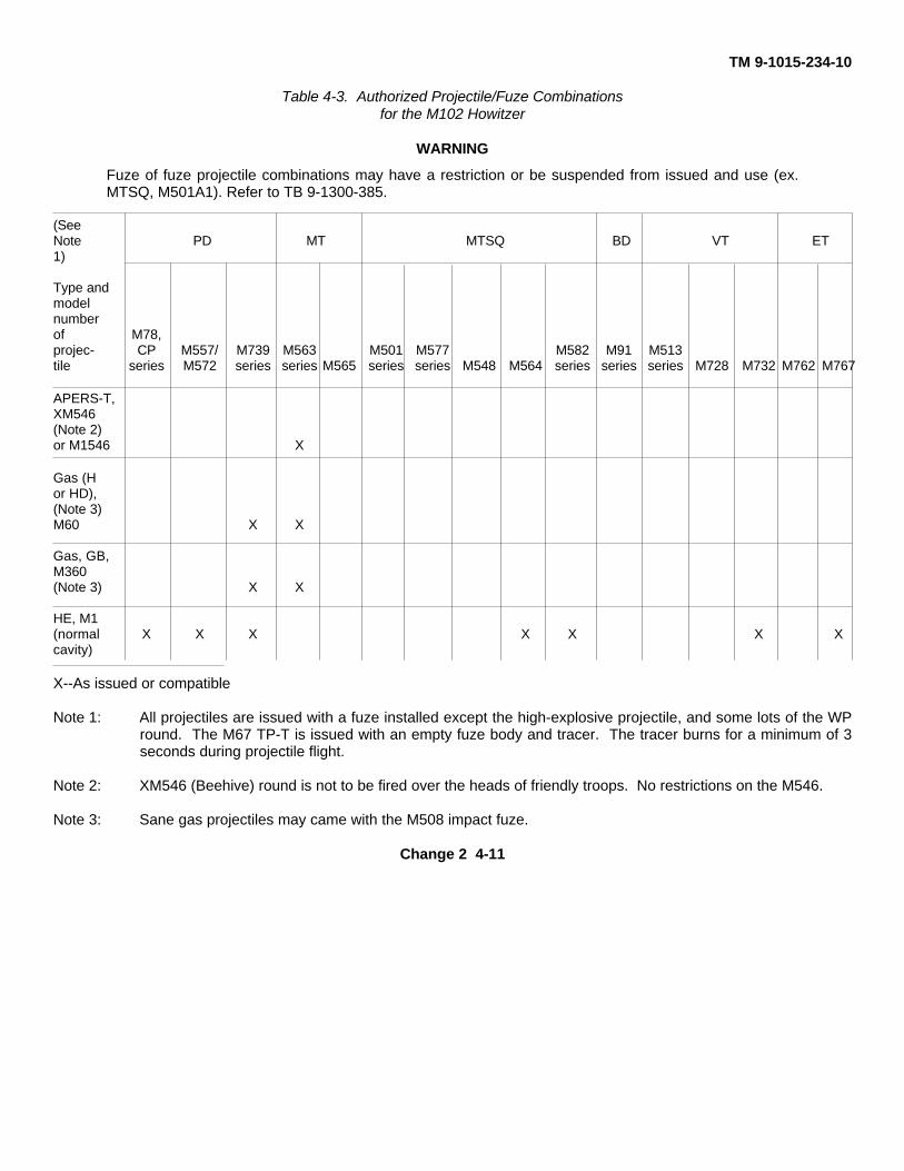
TM 9-1015-234-10
Table 4-3. Authorized Projectile/Fuze Combinationsfor the M102 Howitzer
WARNING
Fuze of fuze projectile combinations may have a restriction or be suspended from issued and use (ex.MTSQ, M501A1). Refer to TB 9-1300-385.
(SeeNote PD MT MTSQ BD VT ET1)
Type andmodelnumberof M78,projec- CP M557/ M739 M563 M501 M577 M582 M91 M513tile series M572 series series M565 series series M548 M564 series series series M728 M732 M762 M767
APERS-T,XM546(Note 2)or M1546 X
Gas (Hor HD),(Note 3)M60 X X
Gas, GB,M360(Note 3) X X
HE, M1(normal X X X X X X Xcavity)
X--As issued or compatible
Note 1: All projectiles are issued with a fuze installed except the high-explosive projectile, and some lots of the WPround. The M67 TP-T is issued with an empty fuze body and tracer. The tracer burns for a minimum of 3seconds during projectile flight.
Note 2: XM546 (Beehive) round is not to be fired over the heads of friendly troops. No restrictions on the M546.
Note 3: Sane gas projectiles may came with the M508 impact fuze.
Change 2 4-11

TM 9-1015-234-104-4. AUTHORIZED FUZES FOR M102 HOWTZER (cont)
Table 4-3. Authorized Projectile/Fuze Combinations
(SeeNote PD MT MTSQ BD VT ET1)
Type andmodelnumberof M78A1,projec- CP M557/ M739 M563 M501 M577 M582 M91 M513tile series M572 series series M565 series series M548 M564 series series series M728 M732 M762 M767
HE, M1(deepcavity(Note 4) X X X X X P P X X
HE,M444(Note 5) X X
HEP/HEP-T,M327 X
Illum,M314 (oldseries) X
Illum,M314A3(new X X X Xseries)
Smoke, BE,M84 (oldseries) X
Smoke, HC,M84A1(newseries) X X X X
Change 2 4-12
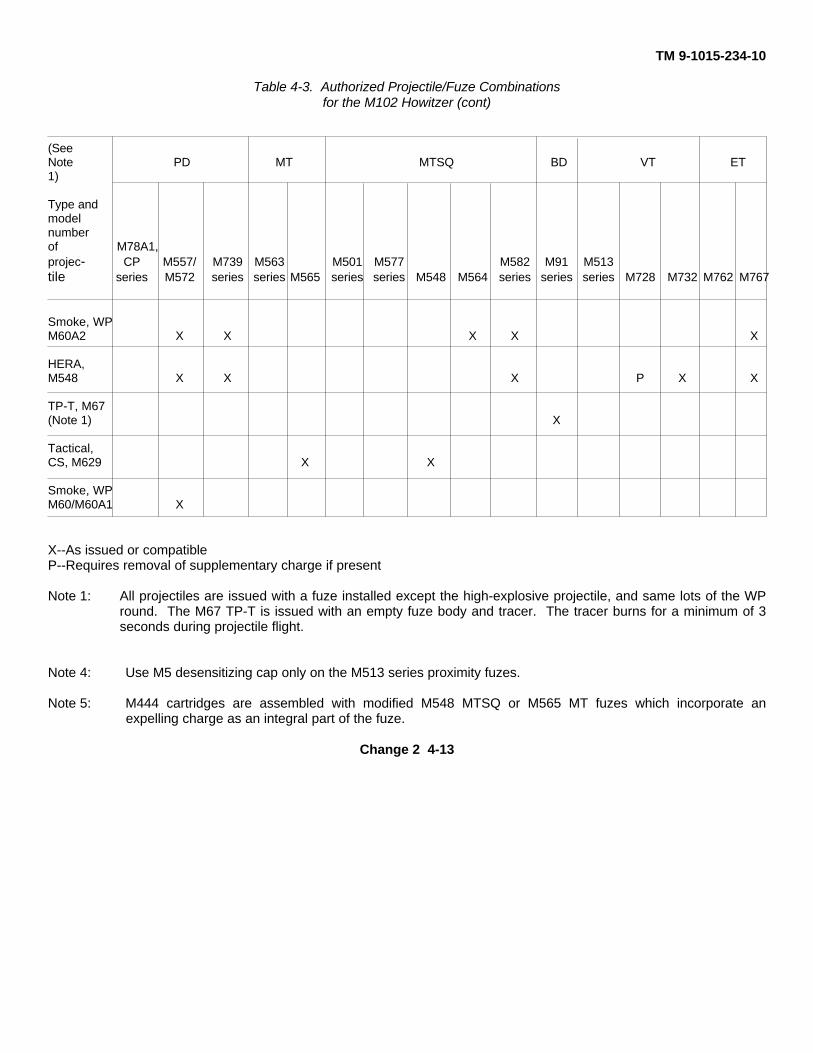
TM 9-1015-234-10
Table 4-3. Authorized Projectile/Fuze Combinationsfor the M102 Howitzer (cont)
(SeeNote PD MT MTSQ BD VT ET1)
Type andmodelnumberof M78A1,projec- CP M557/ M739 M563 M501 M577 M582 M91 M513tile series M572 series series M565 series series M548 M564 series series series M728 M732 M762 M767
Smoke, WPM60A2 X X X X X
HERA,M548 X X X P X X
TP-T, M67(Note 1) X
Tactical,CS, M629 X X
Smoke, WPM60/M60A1 X
X--As issued or compatibleP--Requires removal of supplementary charge if present
Note 1: All projectiles are issued with a fuze installed except the high-explosive projectile, and same lots of the WPround. The M67 TP-T is issued with an empty fuze body and tracer. The tracer burns for a minimum of 3seconds during projectile flight.
Note 4: Use M5 desensitizing cap only on the M513 series proximity fuzes.
Note 5: M444 cartridges are assembled with modified M548 MTSQ or M565 MT fuzes which incorporate anexpelling charge as an integral part of the fuze.
Change 2 4-13
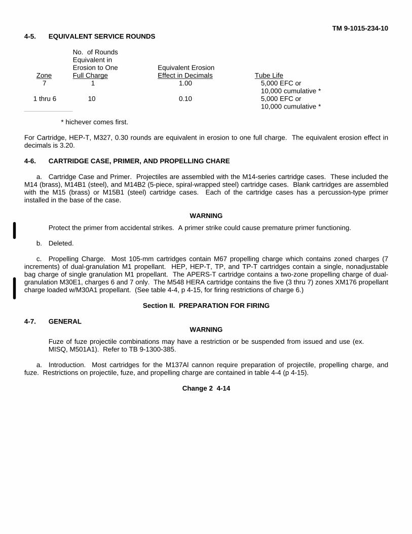
TM 9-1015-234-104-5. EQUIVALENT SERVICE ROUNDS
No. of RoundsEquivalent inErosion to One Equivalent Erosion
Zone Full Charge Effect in Decimals Tube Life7 1 1.00 5,000 EFC or
10,000 cumulative *1 thru 6 10 0.10 5,000 EFC or
10,000 cumulative *
* hichever comes first.
For Cartridge, HEP-T, M327, 0.30 rounds are equivalent in erosion to one full charge. The equivalent erosion effect indecimals is 3.20.
4-6. CARTRIDGE CASE, PRIMER, AND PROPELLING CHARE
a. Cartridge Case and Primer. Projectiles are assembled with the M14-series cartridge cases. These included theM14 (brass), M14B1 (steel), and M14B2 (5-piece, spiral-wrapped steel) cartridge cases. Blank cartridges are assembledwith the M15 (brass) or M15B1 (steel) cartridge cases. Each of the cartridge cases has a percussion-type primerinstalled in the base of the case.
WARNING
Protect the primer from accidental strikes. A primer strike could cause premature primer functioning.
b. Deleted.
c. Propelling Charge. Most 105-mm cartridges contain M67 propelling charge which contains zoned charges (7increments) of dual-granulation M1 propellant. HEP, HEP-T, TP, and TP-T cartridges contain a single, nonadjustablebag charge of single granulation M1 propellant. The APERS-T cartridge contains a two-zone propelling charge of dual-granulation M30E1, charges 6 and 7 only. The M548 HERA cartridge contains the five (3 thru 7) zones XM176 propellantcharge loaded w/M30A1 propellant. (See table 4-4, p 4-15, for firing restrictions of charge 6.)
Section II. PREPARATION FOR FIRING
4-7. GENERALWARNING
Fuze of fuze projectile combinations may have a restriction or be suspended from issued and use (ex.MISQ, M501A1). Refer to TB 9-1300-385.
a. Introduction. Most cartridges for the M137Al cannon require preparation of projectile, propelling charge, andfuze. Restrictions on projectile, fuze, and propelling charge are contained in table 4-4 (p 4-15).
Change 2 4-14
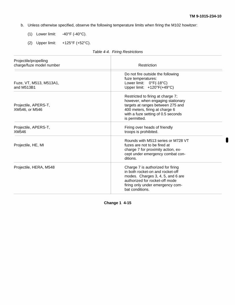
TM 9-1015-234-10
b. Unless otherwise specified, observe the following temperature limits when firing the M102 howitzer:
(1) Lower limit: -40°F (-40°C).
(2) Upper limit: +125°F (+52°C).
Table 4-4. Firing Restrictions
Projectile/propellingcharge/fuze model number Restriction
Do not fire outside the followingfuze temperatures:
Fuze, VT, M513, M513A1, Lower limit: 0°F(-18°C)and M513B1 Upper limit: +120°F(+49°C)
Restricted to firing at charge 7;however, when engaging stationary
Projectile, APERS-T, targets at ranges between 275 andXM546, or M546 400 meters, firing at charge 6
with a fuze setting of 0.5 secondsis permitted.
Projectile, APERS-T, Firing over heads of friendlyXM546 troops is prohibited.
Rounds with M513 series or M728 VTProjectile, HE, MI fuzes are not to be fired at
charge 7 for proximity action, ex-cept under emergency combat con-ditions.
Projectile, HERA, M548 Charge 7 is authorized for firingin both rocket-on and rocket-offmodes. Charges 3, 4, 5, and 6 areauthorized for rocket-off modefiring only under emergency com-bat conditions.
Change 1 4-15
TM 9-1015-234-10
4-8. PACKING AND UNPACKING
a. Packing Procedure.
(1) Projectiles are packed in individual fiber containers. The outer packing consists of a wooden box, metalcontainer, or crate.
(2) Fuzes are generally packed eight to a metal container, two containers to a wooden box (overpack).
b. Unpacking Procedure.
NOTE
Retain packing materials for repacking, as required.
(1) Examine ammunition box marking to determine identification.
(2) Open outer pack and remove fiber container.
CAUTION
Do not use axes, crowbars, or other such implements which maydamage inner pack or ammunition.
(3) Open fiber container and remove cartridge case and projectile.
(4) Remove U-shaped packing stop, if applicable.
(5) Inspect round and assure correctness of nomenclature. Check that round is not damaged or corroded andis free of foreign matter. If necessary, remove foreign matter.
NOTE
Slight amounts of rust do not make the projectile unserviceable. DO NOT remove setscrews or wax plugfrom setscrew hole in projectile.
(6) DO NOT use blank cartridges with loose or broken closing cups; report such items to ammunition officer fordisposal.
(7) Unpack fuze, when issued separately, following steps 4-8b (1), (2), (3), (4), and (5), as applicable.
4-16
TM 9-1015-234-104-9. FUZING
a. Fuze Removal. The Ml, HE projectile may be shipped with fuzes which must be removed if time or proximityfuze action is desired.
(1) Using screwdriver which fully fits screw slot, loosen booster setscrew in nose of projectile, when present.
(2) Insert M18 fuze wrench in wrench slots of fuze, taking care not to strike any part of fuze. Strike wrenchhandle sharply in counterclockwise direction to loosen fuze from projectile. Unscrew and remove fuze with booster.
(3) Inspect cavity and projectile threads for damage. Remove loose material from cavity. If any high explosiveis found adhering to the threaded portion of the projectile throat, reject the round and let qualified ammunition personneldispose of it.
b. Closing Plug Removal.
(1) Using screwdriver which fully fits screw slot, loosen setscrew in nose of projectile (when present).
(2) For metal closing plugs, insert M18 fuze wrench in wrench slots of plug: strike wrench handle sharply incounterclockwise direction. Remove plug and spacer beneath plug.
(3) For plastic nose plugs, pull tab up breaking its sides loose from the plug. Push tab into the center of theplug. Squeeze plug and withdraw it from the fuze well.
(4) Inspect cavity and projectile threads for damage. Remove loose material from cavity. If any high explosiveis found adhering to the threaded portion of the projectile throat, reject the round and let qualified ammunition personneldispose of it.
c. Supplementary Charge.
(1) When preparing rounds for CP, SQ/D, MTSQ, short intrusion VT, and ET fuzes, inspect for presence ofsupplementary charge.
WARNING
Do not fire anything except long intrusion proximity fuzed rounds without supplementary charge, unlessprojectile has shallow cavity.
Change 2 4-17
TM 9-1015-234-104-9. FUZING (cont)
c. Supplementary Charge. (cont)
(2) For long intrusion VT fuze firing, remove supplementary charge as follows:
WARNING
Do not attempt to remove the supplementary charge by any other means than the lifting loop. Use ofscrewdrivers or other tools to remove the charge by force is prohibited.
(a) Remove the supplementary charge by means of the lifting loop. If charge cannot be removed by liftingloop, either fire with SQ/D, short intrusion VT, MISQ, or ET fuze or dispose of round.
(b) Inspect cavity and projectile threads for damage. Remove loose material from cavity. If any high explosiveis found adhering to the threaded portion of the projectile throat, reject the round and let qualified ammunition personneldispose of it.
WARNING
Do not fire artillery ammunition of any caliber without authorized fuze.Firing of such rounds without fuzesor with unauthorized fuzes could result in inbore prematures and other hazardous conditions.
d. Fuze Assembly.
(1) The following procedures apply to all fuzes, except the M78A1 CP fuze I (para 4-9d(2), p 4-19) and M91series base detonating fuzes (para 4-9d(3), p 4-19).
(a) Screw fuze in by hand. If binding occurs, inspect fuze cavity and threads of both fuze and projectile. Rejectwhichever is at fault.
WARNING
When tightening fuze to projectile, do not hammer on fuze wrench. Do not use extension handle on fuzewrench. Do not stake fuze to projectile under any circumstances. Shocks transmitted to fuzes duringassembly may increase percentage of malfunctions.
(b) Using M18 fuze wrench, tighten fuze to projectile so that fuze shoulder is seated flush with nose ofprojectile.
Change 2 4-18
TM 9-1015-234-10WARNING
Do not fire round unless fuze is fully seated. Rounds fired with improperly seated fuzes may result inpremature functioning causing serious injury to personnel and damage to equipment.
NOTE
For VT fuzes with gap between fuze shoulder and projectile, either replace supplementary charge inprojectile and fire with SQ/D, MTSQ, or ET fuze or dispose of round.
(c) If projectile setscrew is present, tighten to below level of contour of projectile.
(2) Special preparations for M78 and M78A1. The booster is not issued assembled to the fuze and must beassembled to the projectile.
(a) Remove safety pin, if present, from M25 booster and screw the booster into the booster cavity of theprojectile. Boosters issued without safety pins should not be used.
(b) Tighten booster, using booster end of M16 fuze wrench.
(c) Screw M78A1 CP fuze into fuze cavity, tighten, using M16 fuze wrench. Make sure fuze shoulder seatsflush against nose of projectile. Do not stake fuze to the projectile.
(d) If projectile setscrew is present, tighten to below level of contour of projectile.
(3) Deleted.
4-10. FUZE SETTING PROCEDURES FOR THE M102 HOWITZER
a. General. The following procedures apply to the authorized fuze/projectile combinations for the M102 howitzer.Fuze setting tools and procedure numbers are listed in table 4-5 (p 4-21).
Change 2 4-19
TM 9-1015-234-10
4-10. FUZE SETTING PROCEDURES FOR THE M102 HOWITZER (cont)
a. General. (cont)
(1) M557 and M572 impact fuzes, M564 and M548 time fuzes, and the proximity VT fuzes may prematurelyexplode when fired during heavy precipitation; i.e., rainfall, sleet, snow, or hail. Precipitation necessary to causemalfunctioning is comparable to heavy downpours which occur during summer thundershowers. In the case of the M557and M572 impact fuzes with delay-action option, setting the fuze for delay-action may prevent prematures; however, seeparagraph 4-10a(2).
(2) M739 series impact fuze, M577 series and M582 series time fuzes, and M762 and M767 electronic timefuzes are not sensitive to rain and may be fired during heavy precipitation.
(3) Any ammunition in the field, with M51A series PD fuze not marked "MODIFIED" will not be used.
CAUTION
Before setting MT, MTSQ, ET, or VT fuzes, refer to the appropriate firing table for required time setting.
b. Procedure No. 1, M557, M572, or M/39 Series. PD fuzes with SQ or delay functioning are shipped set for SQaction. To set fuzes for delay-action use screwdriver end of M18 fuze wrench or similar tool and turn slot 90 degrees toalign with index mark "DELAY" engraved in ogive. When firing fuze for SQ functioning, always check to make sureindex mark is on SQ.
NOTE
Fuzes can be set in the dark by feeling the position of the slot.
c. Procedure No. 2, M501 Series.
WARNING
Dropping or rough handling of a projectile assembled with M501/M501A1 MTSQ fuze may result in fuzefunctioning and expulsion of projectile base plate and contents. When handling projectiles assembledwith the fuze, exercise extreme care to protect the fuze from impact. Keep pull wire on fuze in placeuntil immediately prior to firing.
CAUTION
Do not fire fuzes with cocked or loose lower caps.
NOTE
The M501 series fuzes are shipped with index mark on lower cap aligned with the S engraved on thebase.
Change 2 4-20
TM 9-1015-234-10
Table 4-5. Fuze Setting Tools and Procedures for M102 Howitzer
FUZE (See Note 1)
PD MT MTSQ VT ET
M577 FuzeM78A1 series wrench
CPM557 M572, or or M728 762M orseries M739 M563 M501 M582 M513 or or fuze Procedure
(Note 2) series series M565 series series M548 M564 series M732 M767 setter number
X M18 1
X M16 (Note 2)
X X X M27 2&3
X X X X M34 4
X M35 5
X 6
X -- Denotes compatibility of fuzes and fuze setters.
Note 1: All fuzes are installed and tightened to the nose of the projectile with the 118 fuze wrench, except theM78A1 CP series fees.
Note 2: The M78A1 CP series fuzes and boosters are installed in the projectiles with the M1G fuze wrench. (Seepara 4-9d(2), p 4-19.)
(1) Time setting.
(a) Check fuzes for cocked or loose lower caps.
(b) To remove safety wire before setting, pull end of wire from the hole in the lower cap, sliding wire offend of
Change 2 4-21
TM 9-1015-234-10
4-10. FUZE SETTING PROCEDURES FOR THE M102 HOWITZER (cont)
c. Procedure No. 2, M501 Series. (cont)
(c) With fuze setter, set fuze by rotating lower cap to desired time in counterclockwise direction or in directionof arrow marked on the lower cap. The fuze is properly set when the index mark on the lower cap is alignd with desiredtime, in seconds, engraved on base.
(d) M27 fuze setter will then be used to set the fuze to desired time.
(e) If, after the fuze is set, the round is not fired, reset the fuze to the safe S position and place the safety wirein its proper position.
(2) Impact setting. Impact functioning of the M501 series MTSQ fuze may be obtained either by leaving the S(shipping mark) aligned with the index mark on the base or by setting the graduated time ring so that the time setting isgreater than the time of flight. Remember, you must remove the safety wire (pull free end of wire off and out of hole)before firing or setting the fuze.
d. Procedure No. 3, M513 Series, M728, and M732.
CAUTION
The plastic nose cone will rotate with the index mark. Damage to the plastic will produce duds.However, since there is no backlash, fuze setting can be accomplished or changed one or rmore timesby rotating the index mark in either direction. If counterclockwise rotation is used, be sure that the fuzehas not become loosened from the projectile.
(1) These fuzes are set when index line at base of nose cone is aligned with time, in seconds, engraved on base offuze.
NOTE
Rotation of the M732 fuze nose cone has been experienced at zone 7 (not a safety hazard). If thisoccurs when M732 is set on time for proximity function, PD function might occur instead. In suchinstances, set the fuze to a time of 10 seconds less than the time of flight for proximity function.
Change 1 4-22
TM 9-1015-234-10
(2) To set fuze for proximity action, rotate nose cone with the M27 fuze setter, normally in the clockwisedirection while looking down on the nose of the fuze, until the index mark coincides with the announced time. Fuzesetting can be changed one or more times with no harmful effects.
NOTEThe M728 fuze is shipped with the index mark on the nose cone set at 10 seconds. The M732 is shippedwith the index mark alined with PD. The M513 andM513B1 fuzes are shipped with index mark alinedwith S. The M513Al and M513A2 are shipped with index mark alined with shipping line (long vertical linewith arrow).
CAUTION
Do not use M513 and M513B1 fuzes for PD functioning.
(3) For impact functioning, set M732 fuze to PD mark andM728, M513A1, and M513A2 fuzes to 90 secondsusing M27 fuze setter.
WARNINGDo not fire projectile unless fuze is fully seat-ed. Inbore explosion may result.
(4) Firing temperature limits for M728 and M732 proximity fuzes are -40° to +140° F (-40° to +60° C) and 0° to+120° F (-18° to +49° C) for M513 series.
NOTEDo not attempt to set fuze until just before firing.
Use of M5 desensitizing fuze cap to lower height ofM513 series fuzes is at the option ofthe artillery officer. Desensitizing fuze caps are assembled to the fuze just before firing.
(5) The removal of the supplementary charge is not required to install the M732 short intrusion VT fuze.
Change 1 4-22.1/(4-22.2 blank)
TM 9-1015-234-10
WARNINGTo avoid accidental functioning of PD element inM548 and M564 fuzes, do not drop, roll, or strikefuzes under any circumstances (packaged, unpackaged, or assembled to the projectile); mishandlingcould cause injury or death to personnel.
(1) Set M548 or M564 fuzes for superquick action (impact) as follows:
NOTEDo not set M548 fuze on S for impact (PD) action. Set fuze for 90 seconds. These fuzes are shippedwith the S on the lower cap alined with the 0 on the vernier scale.
The date of manufacture is stamped on the M564fuze body. M564 fuzes manufactured before 1970mustbe set on 90 seconds if superquick action(impact) is desired.M564 fuzes manufactured from January1970 on should be set on S for superquick action.
(a) M564 fuzes manufactured in January 1970 and later: set fuze on S as shipped for superquickaction. Always be sure the S on lower cap is alined with the 0 on vernier scale.
(b) M548 and M564 fuzes manufactured before January1970: use M34 fuze setter to rotate lowercap in direction of the arrow (clockwise) from safe (S) position to the 90.0-secondsetting.
Change 1 4-23
TM 9-1015-234-104-10. FUZE SETTING PROCEDURES FOR THE M102 HOWITZER (cont)
e. Procedure No. 4, M563, M564, m565, and M548 Fuzes. (cont)
(2) Set M563, M564, M565, and M548 fuzes for airburst (time) as follows:
WARNINGIncorrect settings of MT and MTI'SQ fuzes can and have resulted in downrange prematures.
NOTEThe M563 fuze is set MA (muzzle action), or on the time setting desired for the intended range. Refer todispersion patterns on page 4-3 before settingM563 fuze.
(a) To set M548, M563, M564, or M565 fuze for a whole-second time setting, use M34 fuze setter to rotatelower cap in the direction of the arrow (clockwise), until whole number of seconds (i.e., 20.0 seconds) is alined with0mark engraved on vernier scale.
(b) To set M564, M565, or M548 fuze for a tenth of a whole second (i.e., 20.5 seconds), use the M34 fuzesetter to set the fuze for the whole second (20.0 seconds). Next, find the desired tenth of a second mark on vernierscale.(0.5-second mark is between 29 and 30 whole-second marks.)Continue to slightly rotate lower cap in direction ofarrow until adjacent upper right graduation on lower cap scale(in this example, the 30 second mark) is alined with de-sired tenth of a second mark on vernier scale (30 second mark on lower cap scale is now alined with 0.5 second mark onvernier scale).
Change 1 4-24
TM 9-1015-234-10
NOTEThe fuze setting is always indicated by the position of the "0" on the vernier scale. Each vertical mark onupper body (removable portion of fuze)represents one whole second of time. For other than whole-second settings, 0 on lower cap (nonremovable portion of the fuze) must always be to right of whole-second portion of desired fuze setting, and between whole second portion of desired fuze setting andnext 1-second vertical mark (i.e., for a setting of 20.5, 0 is to right of 20-second mark, and midwaybetween 20- and 21-second marks).
An incorrect fuze setting of 20.5 seconds is shown above. If a fuze is set in this way for 20.5 secondsfiring, fuze is actually set on and will function at 10.5 seconds. This would cause the fuze to function 10seconds earlier than desired.
Do not attempt to set the fuze until just before firing.
Change 1 4-24.1
TM 9-1015-234-104-10. FUZE SETTING PROCEDURES FOR THE M102 HOWITZER (cont)
e. Procedure No. 4, M563, M564, m565, and M548 Fuzes. (cont)
(3) If you miss the setting, reset fuze using M34 fuze setter and turn lower cap in the opposite direction(counter-clockwise) 2 or 3 seconds below desired setting. Then rotate lower cap in direction of arrow (clockwise) and setfuze on the correct time.
(4) If prepared for firing, but not fired, reset fuze using M34 fuze setter and turn lower cap in direction of thearrow (clockwise) until S mark on the fuze lower cap is alined with 0 mark on vernier scale (MA on the M563 fuze).
(5) If these fuzes are fired during heavy precipitation(rain, sleet, snow, or hail), occasional downrangepremature functioning may occur. The precipitation necessary to cause malfunctioning is comparable to a heavydownpour which occurs during a summer thunder shower. The premature rate will vary with the charge fired and thedensity of the precipitation.
Change 1 4-24.2
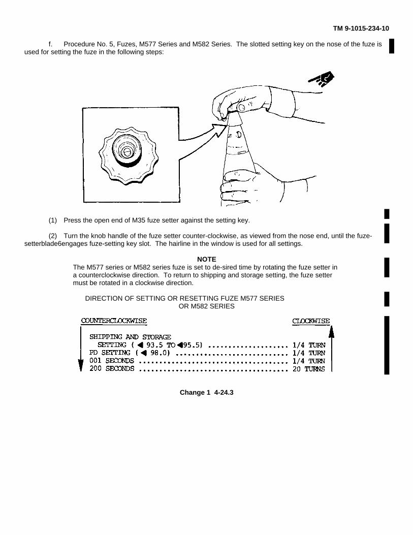
TM 9-1015-234-10
f. Procedure No. 5, Fuzes, M577 Series and M582 Series. The slotted setting key on the nose of the fuze isused for setting the fuze in the following steps:
(1) Press the open end of M35 fuze setter against the setting key.
(2) Turn the knob handle of the fuze setter counter-clockwise, as viewed from the nose end, until the fuze-setterblade6engages fuze-setting key slot. The hairline in the window is used for all settings.
NOTEThe M577 series or M582 series fuze is set to de-sired time by rotating the fuze setter ina counterclockwise direction. To return to shipping and storage setting, the fuze settermust be rotated in a clockwise direction.
DIRECTION OF SETTING OR RESETTING FUZE M577 SERIESOR M582 SERIES
Change 1 4-24.3
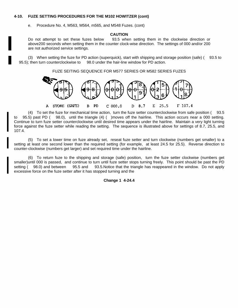
4-10. FUZE SETTING PROCEDURES FOR THE M102 HOWITZER (cont)
e. Procedure No. 4, M563, M564, m565, and M548 Fuzes. (cont)
CAUTIONDo not attempt to set these fuzes below ⇐ 93.5 when setting them in the clockwise direction orabove200 seconds when setting them in the counter clock-wise direction. The settings of 000 and/or 200are not authorized service settings.
(3) When setting the fuze for PD action (superquick), start with shipping and storage position (safe) (⇐ 93.5 to⇐ 95.5); then turn counterclockwise to ⇐ 98.0 under the hair-line window for PD action.
FUZE SEITING SEQUENCE FOR M577 SERIES OR M582 SERIES FUZES
(4) To set the fuze for mechanical time action, turn the fuze setter counterclockwise from safe position (⇐ 93.5to⇐ 95.5) past PD (⇐ 98.0), until the triangle (4) (⇐)moves off the hairline. This action occurs near a 000 setting.Continue to turn fuze setter counterclockwise until desired time appears under the hairline. Maintain a very light turningforce against the fuze setter while reading the setting. The sequence is illustrated above for settings of 8.7, 25.5, and107.4.
(5) To set a lower time on fuze already set, reseat fuze setter and turn clockwise (numbers get smaller) to asetting at least one second lower than the required setting (for example, at least 24.5 for 25.5). Reverse direction tocounter-clockwise (numbers get larger) and set required time under the hairline.
(6) To return fuze to the shipping and storage (safe) position, turn the fuze setter clockwise (numbers getsmaller)until 000 is passed, and continue to turn until fuze setter stops turning freely. This point should be past the PDsetting (⇐ 98.0) and between ⇐ 95.5 and ⇐ 93.5.Notice that the triangle has reappeared in the window. Do not applyexcessive force on the fuze setter after it has stopped turning and the
Change 1 4-24.4

TM 9-1015-234-10
setting is between ⇐ 95.5 and ⇐ 93.5.Return the fuze to the reuseable fuze container.
(7) For special preparation for M577 series fuze, perform the following procedure. Inspect the fuze setting.The fuze will be considered unserviceable if the setting is not between ⇐ 93.5 and ⇐ 95.5, the fuze shows signs ofdamage, or the window is blackened or sooty inside.
(8) Firing temperature limits for M577 series and M582 series MTSQ fuzes are -35° to +145°F (-37° to +63° C).
Change 1 4-24.5/(4-24.6 blank)
TM 9-1015-234-10
g. Procedure No. 6, Fuzes, M762 and M767. These fuzes can be set either by hand or remotely by aweapon equipped with auto-set fire control system, as follows:
CAUTIONDo not activate these fuzes unless they will be fired before 15 days elapse. Once activated, these fuzeshave a service life of approximately 15 days before the battery runs down. Check if ILD is active todetermine if fuze is still settable.
(1) Setting by hand:CAUTION
After steps (a) and (b) are completed, if the LCD display is blank or shows other displays than indi-cated,the fuze is considered unserviceable and should not be fired.
NOTEThe M762 or M767 fuze ogive will rotate only clockwise (as viewed from nose end). If adesired digit was passed, continue rotating clockwise until the desired digit appearsagain.
(a) Rotate ogive clockwise at least one quarter revolution to activate the battery. The liquid crystaldis-play (LCD) window will display ⇐ 88.8 indicating that all segments are operating as a visual safety check.
(b) Depress the thumb operated cocking and selector button to clear the LCD display. The LCDwindow will display---.- ensuring that no segments are stuck.
(c) Depress the thumb operated cocking and selector button a second time; the LCD window willdisplay 000.0.The cursor under the zero in the hundreds of seconds column indicates that this column is ready to be set.
NOTEThe hundreds of seconds column can display 0, 1, or ⇐ while the tens of seconds,seconds, and tenths of seconds columns each can display 0 through 9.
(d) Each column is set independently. Depress and release the selector button as required to move thecursor to the desired column. At the desired column, keep the selector
Change 1 4-25
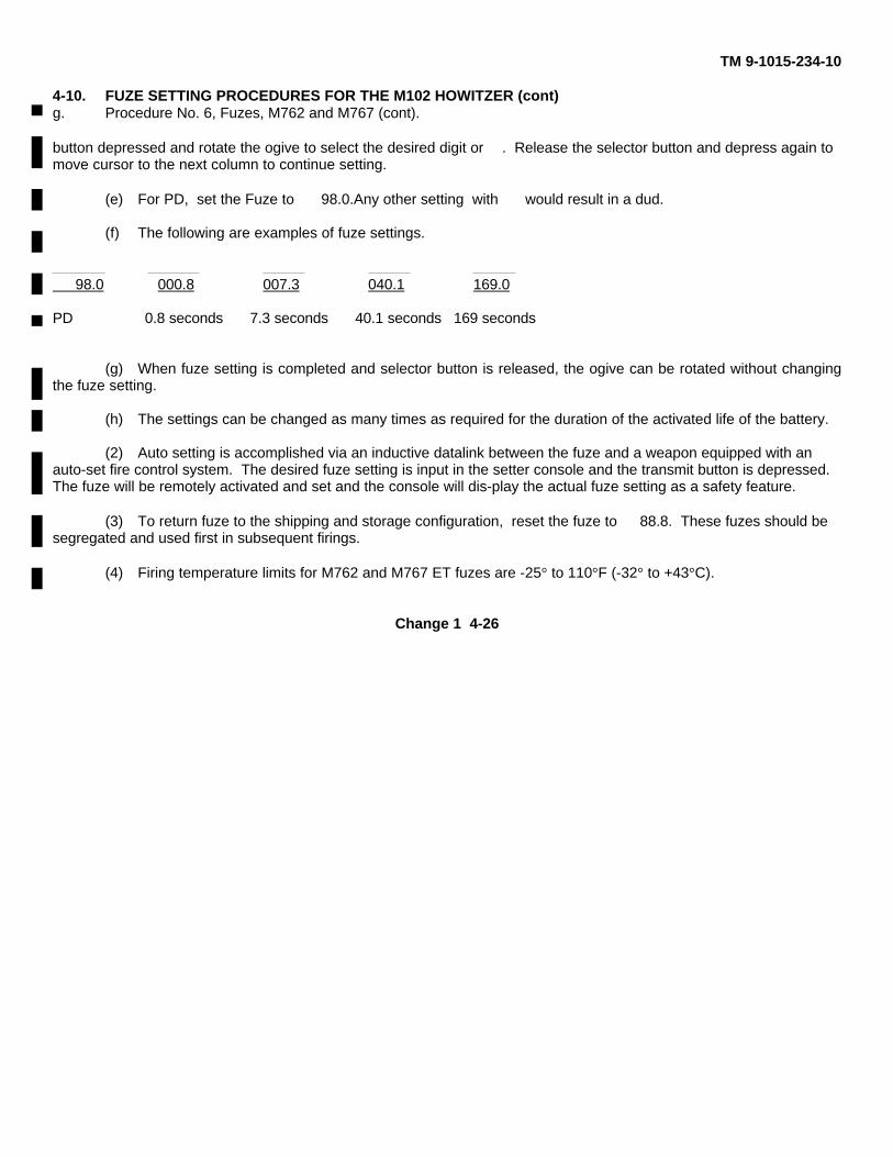
TM 9-1015-234-10
4-10. FUZE SETTING PROCEDURES FOR THE M102 HOWITZER (cont)g. Procedure No. 6, Fuzes, M762 and M767 (cont).
button depressed and rotate the ogive to select the desired digit or ⇐. Release the selector button and depress again tomove cursor to the next column to continue setting.
(e) For PD, set the Fuze to ⇐ 98.0.Any other setting with ⇐ would result in a dud.
(f) The following are examples of fuze settings.
⇐ 98.0 000.8 007.3 040.1 169.0
PD 0.8 seconds 7.3 seconds 40.1 seconds 169 seconds
(g) When fuze setting is completed and selector button is released, the ogive can be rotated without changingthe fuze setting.
(h) The settings can be changed as many times as required for the duration of the activated life of the battery.
(2) Auto setting is accomplished via an inductive datalink between the fuze and a weapon equipped with anauto-set fire control system. The desired fuze setting is input in the setter console and the transmit button is depressed.The fuze will be remotely activated and set and the console will dis-play the actual fuze setting as a safety feature.
(3) To return fuze to the shipping and storage configuration, reset the fuze to ⇐ 88.8. These fuzes should besegregated and used first in subsequent firings.
(4) Firing temperature limits for M762 and M767 ET fuzes are -25° to 110°F (-32° to +43°C).
Change 1 4-26
TM 9-1015-234-10
TYPICAL DEEP-CAVITY PROJECTILES
NOTEThe supplementary charge must be left in the projectile when firing short intrusion fuzes. Thesupplementary charge must be removed when firing the long intrusion VT fuzes.
Change 1 4-27
TM 9-1015-234-10
4-11. PREPARING PROPELLING CHARGE
WARNINGFire complete round only with projectile, cartridge case, and propelling charge type as originally packed.
a. General. Cartridges with an adjustable (semifixed)propelling charge have the charge divided intoincrement charges. When the cartridges are fired full charge, the charge is used as issued. When other than full chargeis to be fired, adjust the propelling charge as indicated in paragraph 4-11b.
CAUTIONUnder no conditions will the fixed charge of the HEP, HEP-T, and TP-T cartridges be altered. Maximumpenetration of armored targets is secured with the fixed charges furnished.
b. Procedure For Preparing M67 Propelling Charge.
(1) Remove projectile from cartridge case, being careful not to damage lip of case (otherwise, cartridge mayjam in chamber of M137A1 cannon).
(2) Withdraw increments from cartridge case. Excess powder increments will be disposed of as directed by thesection chief.
(3) Reassemble remaining increments (up to and including numbered charge to be fired) in cartridge case, inoriginal order. For example, when adjusting seven-section charge for charge four, discard increments five, six, andseven, and assemble remaining increments one, two, three, and four in cartridge case.
NOTEInsofar as the propelling charge is concerned, the cartridge is now ready for firing after it has been matedto the case and loaded into the powder chamber.
If the M548 HERA cartridge is to be fired in the rocket-on mode, the rocket cap must be removed-prior toreplacing the projectile in the cartridge case.
Change 2 4-28
TM 9-1015-234-104-12. PROCEDURE FOR LOADING
WARNINGDo not reuse cartridges which have been ejected from weapons by ramming. Ejection difficulty mayhave been caused by some nonstandard condition in the ammunition and, also, the fuze may havebeen damaged during the ramming process.
a. Ensure round is clean.b. Ensure that there are no obstructions in the M137A1 cannon.
c. Remove fuze safety devices after assembling projectile to cartridge case and just before loading projectilesinto the weapon.
d. Load, taking care not to strike the fuze against the weapon.
e. Do not fire an unfuzed round.
NOTEThe mouth of the M14B2 (M14E1) cartridge case can be expanded slightly by uncoiling, making it easierto insert the projectile. However, if the loader is not careful to grasp the projectile at its center ofbalance the lip may protrude enough to catch on the lip of the lower extractor recess making itimpossible to chamber the round.
4-13. EXCESSIVE PRESSURE IN M137A1 CANNONObserve the following precautions to prevent excessive pressure in the M137A1 cannon:
a. Do not load or fire ammunition which is at a temperature above safe limits for firing.
b. In case of a round chambered in a hot weapon, fire or unload immediately.
c. Use only propelling charges authorized for the particular round.
d. Use no more propellant than in the full charge authorized for the round.
4-29
TM 9-1015-234-10
4-14. DUDSDo not touch, move, or otherwise handle duds; their fuzes may be armed. Have duds destroyed in place by authorizedpersonnel only.
4-15. FIRING TABLES
Firing table 105-AS-3 provides firing data for ammunition fired in the M137Aicannon, except as indicated: Round M444-Firing table 105-ADD-F-1.
4-16. AMMUNITION PREPARED FOR FIRING BUT NOT FIRED
WARNINGIf the cannon tube is hot, chambered rounds should be fired or removed from the weapon within 5minutes.
a. Unloading Operation. A complete round will be removed under the direct supervision of an officer,exercising appropriate precautions. This operation is as follows:
(1) Level the M137A1 cannon and slowly move the breechblock to its open position.
(2) Remove the cartridge case and charge.
(3) Fill the chamber with a shock-absorbent material and close the breech.
(4) Assemble the ramming and extracting tool head to the assembled cleaning staff sections.
(5) Insert the ramming and extracting tool head into the muzzle until it fits around the fuze of the projectile.Then push or, if necessary, tap the staff until the projectile is dislodged from its seat.
(6) Open the breech, remove the shock-absorbent material, and carefully remove the projectile.
b. Ammunition Preparations After Removal.
Change 2 4-30
TM 9-1015-234-10
WARNINGDo not use rounds extracted from weapons by ramming. Extraction difficulty may have been caused bysome nonstandard condition in the ammunition, or the fuze may have been damaged during theramming process.
(1) Using applicable setter and procedure (table 4-5, p4-21), reset fuze to safe. M762/M767 ET fuzes that havebeen activated and not fired should be reset to ⇐ 88.8, segregated, and used first in subsequent firings. When thebattery runs down on an activated M762/M767 fuze, the LCD goes blank. These fuzes are unserviceable and should bepacked separately, marked unserviceable, and turned in to the ammunition supply point (ASP).To determine if anM762/M767 fuze has been activated and run down, gently attempt to turn the ogive clockwise by hand withoutdepressing the selector button. If the ogive turns easily, the fuze has been activated. A fuze that has not been activatedshould resist the applied torque.
(2) Replace safety wires, remove fuze, and replace in original packing.
(3) Disassemble cartridge case and replace projectile and cartridge case in original packing.(See para 4-18.)
4-17. AMMUNITION FORMS AND RECORDS
Record the number of rounds by types fired on DA Form 2408-4. This must be done on a daily basis when fired.
Section III. MAINTENANCE OF AMMUNITION
4-18. MAINTENANCE OF AMMUNITION
WARNINGHandle explosive ammunition and components containing explosives with utmost care. Do not drop,throw, tumble, or strike packaged or unpackaged ammunition or related components. Explosiveelements in primers and fuzes are sensitive to shock.
Do not expose ammunition and components to direct sunlight, flame, or other sources of heat.
Do not expose ammunition and components containing explosives to rain, excessive humidity, orground moisture; otherwise, short ranges may result.
Change 1 4-31
TM 9-1015-234-10
4-18. MAINTENANCE OF AMMUNITION (cont)
a. Care.
(1) Ammunition is packed to withstand conditions ordinarily encountered in the field. Keep packing boxes frombecoming broken or damaged.
(2) Since ammunition is impaired by moisture, frost, extreme temperatures, and foreign matter (mud, oil, etc.)observe the following:
(a) Do not break the moisture-resistant seal on the container until ammunition is to be used.
(b) Shield ammunition, particularly fuzes and propelling charges, from sources of high temperatures (e.g., thedirect rays of the sun).
b. Handling.
(1) Cartridge cases are dented easily and should be protected from hard knocks and blows. A dented cartridgecase may result in loss of obturation, prevent chambering, cause jamming in the chamber, and difficulties in extraction.
(2) Protect propellant from moisture and foreign matter during handling. Keep mouth of cartridge casecontaining propellant covered when moving ammunition.
(3) Protect fuzes, primers, and rotating bands at all times from foreign matter and impact.
(4) Proximity-fuzed ammunition may be safely transported short distances, with normal care and handling.When such ammunition is to be transported considerable distances, it is advisable to transport the fuze in its originalcontainer.
c. Maintenance.
WARNINGAlteration of loaded ammunition or components is prohibited.
(1) Procedures.
Change 1 4-32

TM 9-1015-234-10
(a) Inspect ammunition packaging daily. Open boxes or containers which show severe evidence ofcontamination or deterioration, and inspect ammunition. Do not open sealed boxes or containers for inspectionpurposes only.
(b) Inspect unpackaged ammunition and explosive components daily. Do not open sealed boxes or containersfor inspection purposes only.
Change 1 4-32.1/(4-32.2 blank)
TM 9-1015-234-10
(c) Wipe off wet or dirty ammunition at once. Remove light corrosion or the green or bluish deposits formed oncopper, brass, or bronze surfaces as a result of exposure to the weather.
CAUTIONDo not polish ammunition to make it look better.
(d) Consider ammunition which exhibits severe rust or propellant contamination, particularly moisture,unserviceable. Do not use except in emergencies.
(e) Repackage serviceable ammunition in original containers, ensuring that all material is dry and sound. Iforiginal container is unsuitable, use expended packing material and transfer all markings.
(2) Ammunition or components of ammunition prepared for firing but not fired.
(a) Return such ammunition to the original condition and packing. Mark appropriately and use first insubsequent firings in order to keep stocks of open packings to a minimum.
(b) Reassemble the supplementary charge and closing plug (with gasket and spacer) or fuze to theprojectile to restore the round to its original condition. Return fuzes to original packaging. In reassembling thecomponents, make sure the supplementary charge is properly inserted (felt-pad end innermost). When necessary,plastic nose plugs can be reused. Secure loose plugs with tape.
(3) Unserviceable ammunition.
(a) Conspicuously mark unserviceable ammunition or explosive components UNSERVICEABLE, andreturn to ammunition supply personnel for disposition.
(b) Repackage the ammunition in original containers. If original container is unsuitable, use expendedpacking material and transfer all markings. All layers of packing must be conspicuously marked UNSERVICEABLE.
(4) Excess explosive components. Pack supplementary charges removed from projectiles prior to assemblingVT fuzes in the containers from which the VT fuzes were removed. Properly mark the container and return to theammunition supply personnel for disposition.
Change 2 4-33
TM 9-1015-234-10
4-18. MAINTENANCE OF AMMUNITION (cont)
d. Storage.
WARNINGAmmunition exposed directly to sunlight, or in unventilated containers, enclosures, shelters, freightcars, closed vehicles, and similar structures exposed to direct sunlight, may reach temperaturesexceeding upper storage limits. Avoid exposure of ammunition and ammunition components to directsunlight.
Do not store ammunition under trees or adjacent to towers or other structures that attract lightning.When ammunition must be stored in the open, select a storage site free of power lines, electric cables,and readily ignitable and flammable materials. Site should be level and well drained.
Do not store ammunition assembled with tetrytol-loaded bursters (e.g., cartridges, 105-mm: Smoke,WP, M60; gas, H and HD, persistent, M60) at temperatures exceeding +125°F(51.7°C).
NOTEAmmunition assembled with bursters containing COMPB5 can be stored at temperatures up to+145°F(62.80C).
(1) Temperature limits.
(a) Except as otherwise specified, observe the following limits: Lower limit: -80°F(-62.2°C) for periods of notmore than three days; upper limit: +160°F(71.1°C) for periods of not more than four hours per day.
(b) Store or transport projectiles containing WP at temperatures below the melting point (+111.4°F (44.1°C)) ofthe WP filler. If this is not practicable, store or transport such projectiles on their bases so that, should the WP fillermelt, it will resolidify with the void in the nose of the projectile. Complete rounds of recent manufacture are packed inboxes marked NOSE END.
4-34
TM 9-1015-234-10
(c) Protect VT fuzes and VT-fuzed rounds from long exposure to high humidity. Observe the followingtemperature limits:
Lower Limit Upper Limit
-20°F (-28.90C) +130°F (54.4°C) (M513, M513B1) I
-40°F (-40 C) +130° F (54.4°C) (M513A1)
-60°F (-51.110C) +160°F (71.1°C) (M513A2)
-40°F (-400C) +140°F (60°C) (M728, M732)
(2) Provisions.
(a) Use heavy, well supported dunnage to keep the bottom tier of the stack off the ground and toprevent it from sinking into the ground.
NOTEA hardstand of blacktop or gravel and sand is preferable to excessive use of dunnage. Allow at least 6inches of space beneath the pile for air circulation. Dig suitable trenches to prevent water from flowingunder the pile.
(b) Provide nonflammable or fire-resistant covers (e.g., tarpaulin) for all ammunition. Maintain an airspace of approximately 18 inches between the cover and the ammunition. Keep the cover at least 6 inches from the pileon the ends and at the sides, to permit circulation of air.
(c) Store WP rounds nose up.
(d) Store ammunition containers with top side up. Labels or markings on boxes and containersindicate which side should be up.
Change 1 4-35 (4-36 blank)
TM 9-1015-234-10APPENDIX A
REFERENCES
A-1. DEPARTMENT OF THE ARMY (DA) FORMS
DA Form 2028-2 ................................... Recommended Changes to Equipment Technical Publications
DA Form 2404....................................... Equipment Inspection and Maintenance Worksheet
DA Form 2408-4 ................................... Weapon Record DataA-2FIELD MANUALS (FM)
FM 3-87 ................................................ Nuclear, Biological, and Chemical Reconnaissance and DecontaminationOperations
FM 6-50 ................................................ The Field Artillery Cannon Battery
FM 9-207 .............................................. Operation and Maintenance of OrdnanceMateriel in Cold Weather (O to -650F)
FM 21-11 (TEST ................................... )First Aid for Soldiers
FM 21-15 .............................................. Care and Use of Individual Clothingand Equipment
FM 21-40 .............................................. NBC (Nuclear, Biological and Chemical)Defense
FM 31-70 .............................................. Basic Cold Weather Manual
FM 31-71 .............................................. Northern Operations
FM 55-450-1 ......................................... Army Helicopter External Load Operations
FM 55-450-2 ......................................... Army Helicopter Internal Load Operations
Change 1 A-1
TM 9-1015-234-10
A-3. TECHNICAL MANUALS (TM)
TM 3-4230-204-12&P.............. Operator's and Organizational Maintenance Manual for Decontamination ApparatusPortable: DS-2
TM 9-1000-202-14 .................. Operator's, Organizational, Direct Support, and General Support MaintenanceManual for Evaluation of Cannon Tubes
TM 9-1015-234-10-HR ............ Hand Receipt Manual Covering Basic Issue Items (BII) and Additional AuthorizationList (AAL) Related to Howitzer, Light, Towed: 105-MM, M102
TM 9-1290-359-12&P.............. Operator and Organizational Maintenance Manual for the M90 Radar Chronograph
TM 9-238 ................................ Deepwater Fording of Ordnance Materiel
TM 9-4931-710-14&P Operator, Organizational, Direct Support, and General Support Maintenance Manual for Alignment Device M139 and M140 with Case
TM 11-5820-882-10................. Operator's Manual; Radio Set, AN/PRC-68
TM 11-7440-283-12-1.............. Operator's and Organizational Maintenance Manual; Computer, Gun Direction CP1317/GYK-29
TM 11-7440-283-12-2.............. Operator's and Organizational Maintenance Manual; Data Display Group OD-144/GYK-29
TM 43-0001-28........................ Army Ammunition Data Sheets for Artillery Ammunition: Guns, Howitzers, Mortars,Recoilless Rifles, Grenade Launchers, and Artillery Fuzes (FSC 1310, 1315, 1320,
1390)
TM 43-0001-28-10 Artillery Ammunition: Authorized Projectile, Fuze and Propelling Charge Combinations for Howitzer, Light, Towed, 105-mm: M101, M1O1Al, and M102
Change 2 A-2

TM 9-1015-234-10
A-4. OTHER
AR 25-30...................... The Army Integrated Publishing and Printing Program
CTA 8-100 ................... Army Medical Department Expendable/Durable Items
CTA 50-970.................. Expendable/Durable Items (Except Medical, Class V, Repair Parts, and Heraldic Items)
DA PAM 738-750 The Army Maintenance Management System (TAMMS), as contained in Maintenance Management Update
SF Form 368................ Quality Deficiency Report
TB 9-1300-385 ............. Munitions, Restricted or Suspended
10 CFR Part 19 ............ Notices, Instructions and Reports to ]0/ C ~ k Pat 19 Workers; Inspections
10 CFR Part 20 ............ Standards for Protection Against Radiation
Change 1 A-3 (A-4 blank)
TM 9-1015-234-10
APPENDIX B
COMPONENTS OF END ITEM AND BASIC ISSUE ITEMS LISTS
Section I. INTRODUCTIONB-1. SCOPE
This appendix lists components of end item and basic issue items for the M102 howitzer to help you inventory itemsrequired for safe and efficient operation.
B-2. GENERAL
The Components of End Item and Basic Issue Items Lists are divided into the following sections:
a. Section II. Components of End Item. This listing is for informational purposes only, and is not authorityto requisition replacements. These items are part of the end item, but are removed and separately packaged fortransportation or shipment. As part of the end item, these items must be with the end item whenever it is issued ortransferred between property accounts. Illustrations are furnished to assist you in identifying the items.
b. Section III. Basic Issue Items. These are the minimum essential items required to place the M102howitzer in operation, to operate it, and to perform emergency repairs. Although shipped separately packaged, BII mustbe with the M102 howitzer during operation and whenever it is transferred between property accounts. The illustrationswill assist you with hard-to identify items. This manual is your authority to request/requisition replacement BII, based onTOE/MTOE authorization of the end item.
B-3. EXPLANATION OF COLUMNS
The following provides an explanation of columns found in the tabular listings:
a. Column (1) - Illustration Number (IIIus Number). This column indicates the number of the illustration inwhich the item is shown.
B-1

TM 9-1015-234-10
B-3. EXPLANATION OF COLUMNS (cont)
b. Column (2) - National Stock Number. Indicates the National Stock number assigned to the item and will beused for requisitioning purposes.
c. Column (3) - Description. Indicates the Federal item name and, if required, a minimum description toidentify and locate the item. The last line for each item indicates the FSCM (in parentheses) followed by the partnumber.
d. Column (4) - Unit of Measure (U/M).Indicates the measure used in performing the actualoperational/maintenance function. This measure is expressed by a two-character alphabetical abbreviation (e.g., ea, in.,pr).
e. Column (5) - Quantity required (Qty reqd). Indicates the quantity of the item authorized to be used with/onthe equipment.
B-2
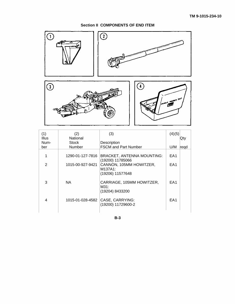
TM 9-1015-234-10
Section II COMPONENTS OF END ITEM
(1) (2) (3) (4)(5)Illus National QtyNum- Stock Descriptionber Number FSCM and Part Number U/M reqd
1 1290-01-127-7816 BRACKET, ANTENNA MOUNTING: EA1(19200) 11785066
2 1015-00-927-9421 CANNON, 105MM HOWITZER, EA1M137A1:(19206) 11577648
3 NA CARRIAGE, 105MM HOWITZER, EA1M31:(19204) 8433200
4 1015-01-028-4582 CASE, CARRYING: EA1(19200) 11729600-2
B-3
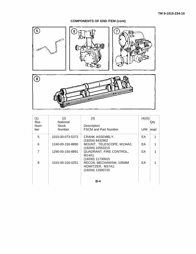
TM 9-1015-234-10
COMPONENTS OF END ITEM (cont)
(1) (2) (3) (4)(5)Illus National QtyNum- Stock Descriptionber Number FSCM and Part Number U/M reqd
5 1015-00-073-5372 CRANK ASSEMBLY: EA 1(19204) 8432902
6 1240-00-150-8890 MOUNT, TELESCOPE, M134A1: EA 1(19200) 10553215
7 1290-00-150-8891 QUADRANT, FIRE CONTROL, EA 1M14A1:(19200) 11730915
8 1015-00-316-0251 RECOIL MECHANISM, 105MM EA 1HOWITZER, M37A1:(19204) 12000725
B-4

TM 9-1015-234-10
(1) (2) (3) (4)(5)Illus National QtyNum- Stock Descriptionber Number FSCM and Part Number U/M reqd
9 5305-00-983-7466 SCREW, CAP, SOCKET HEAD: EA 1(96906) MS16997-148
1 05305-00-958-7483 SCREW, CAP, SOCKET HEAD: EA 2(96906) MS16997-151
11 1015-00-987-8738 STAKE, CARRIAGE: 24-in. EA 8long(19204) 8436590
12 1015-00-658-0794 STAKE, CARRIAGE: 38-in. EA 4long(19204) 8436773
13 1240-00-150-8889 TELESCOPE, ELBOW, M114A1: EA 1(19200) 11730285
B-5
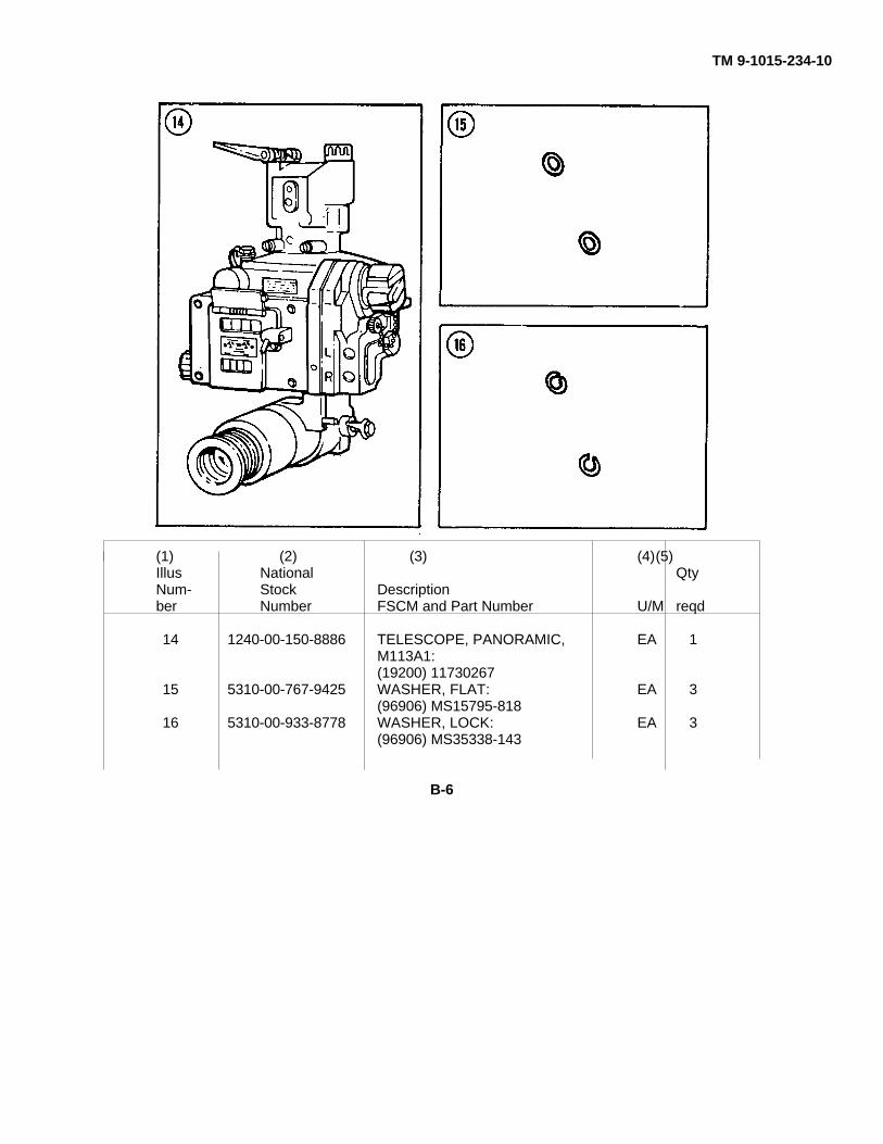
TM 9-1015-234-10
(1) (2) (3) (4)(5)Illus National QtyNum- Stock Descriptionber Number FSCM and Part Number U/M reqd
14 1240-00-150-8886 TELESCOPE, PANORAMIC, EA 1M113A1:(19200) 11730267
15 5310-00-767-9425 WASHER, FLAT: EA 3(96906) MS15795-818
16 5310-00-933-8778 WASHER, LOCK: EA 3(96906) MS35338-143
B-6
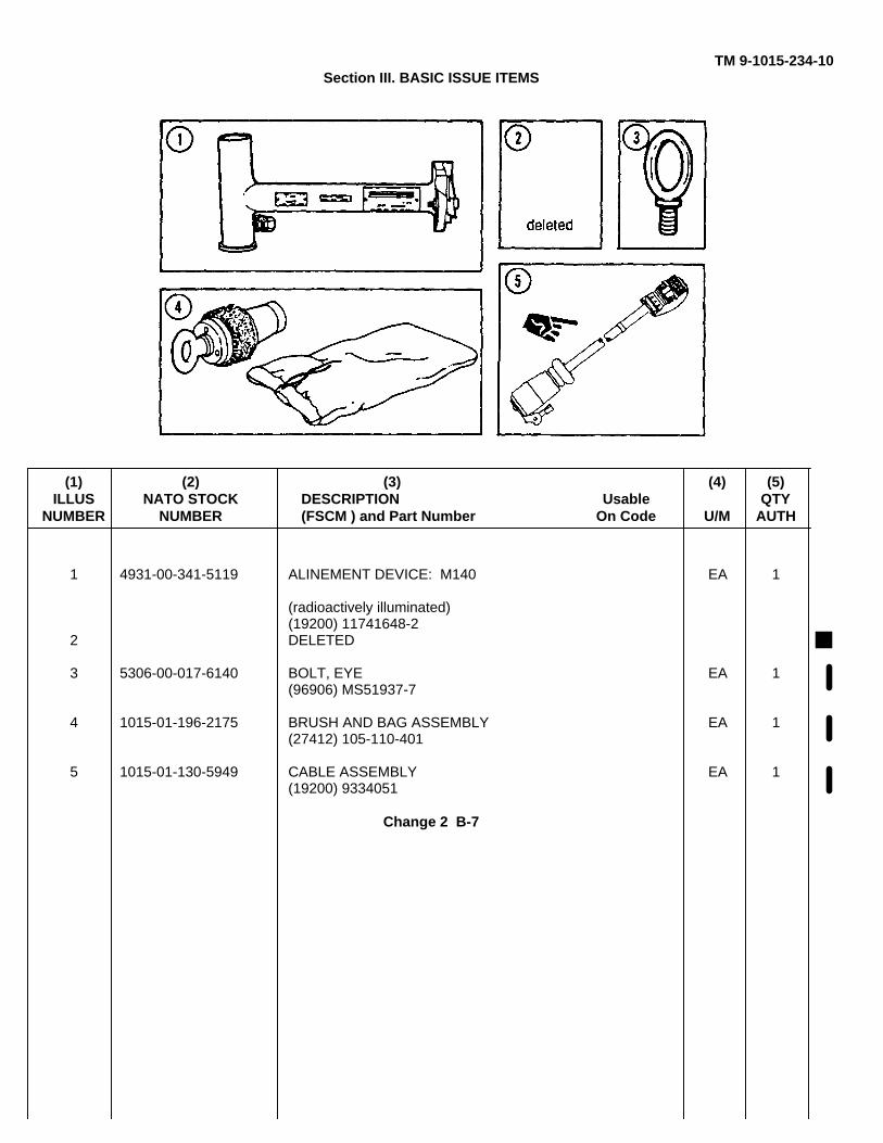
TM 9-1015-234-10Section III. BASIC ISSUE ITEMS
(1) (2) (3) (4) (5)ILLUS NATO STOCK DESCRIPTION Usable QTY
NUMBER NUMBER (FSCM ) and Part Number On Code U/M AUTH
1 4931-00-341-5119 ALINEMENT DEVICE: M140 EA 1
(radioactively illuminated)(19200) 11741648-2
2 DELETED
3 5306-00-017-6140 BOLT, EYE EA 1(96906) MS51937-7
4 1015-01-196-2175 BRUSH AND BAG ASSEMBLY EA 1(27412) 105-110-401
5 1015-01-130-5949 CABLE ASSEMBLY EA 1(19200) 9334051
Change 2 B-7
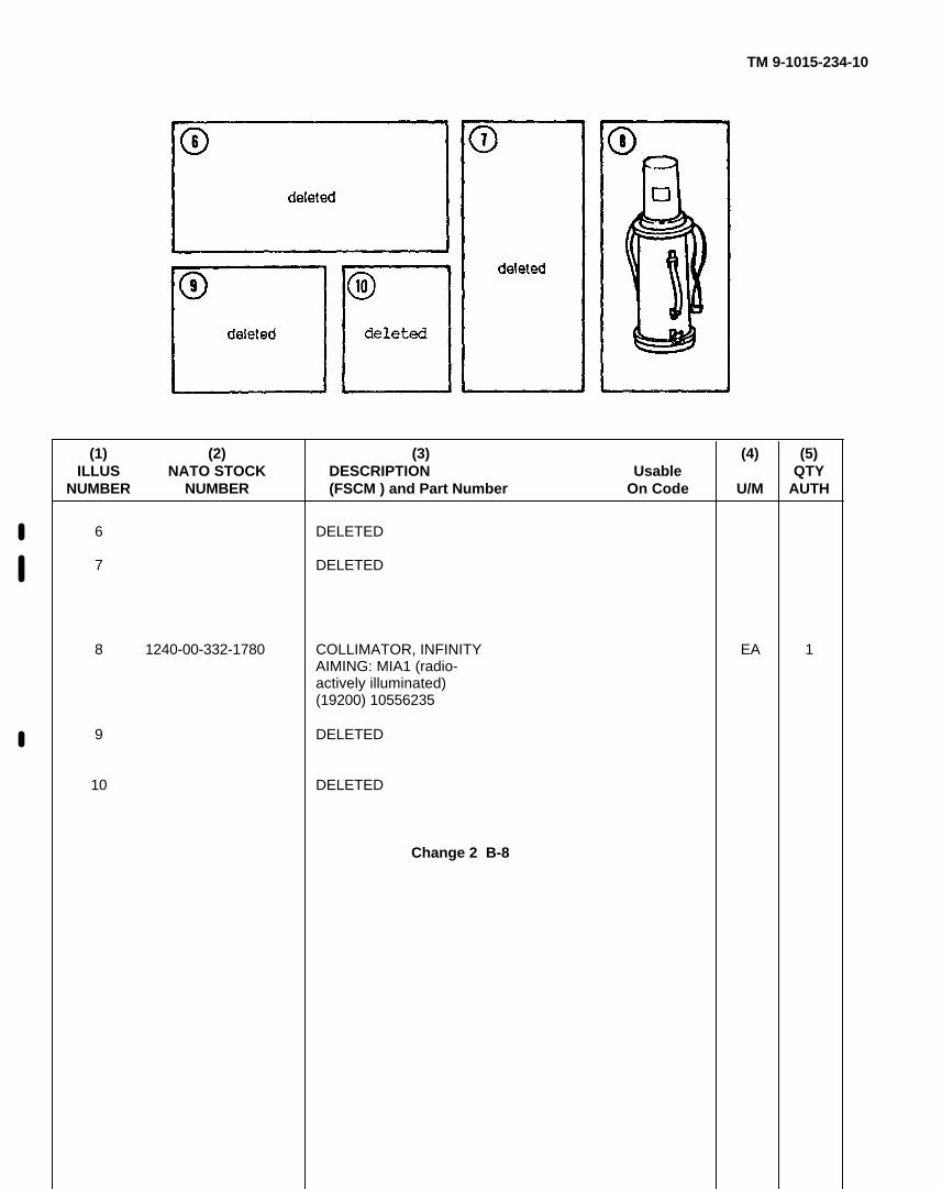
TM 9-1015-234-10
(1) (2) (3) (4) (5)ILLUS NATO STOCK DESCRIPTION Usable QTY
NUMBER NUMBER (FSCM ) and Part Number On Code U/M AUTH
6 DELETED
7 DELETED
8 1240-00-332-1780 COLLIMATOR, INFINITY EA 1AIMING: MIA1 (radio-actively illuminated)(19200) 10556235
9 DELETED
10 DELETED
Change 2 B-8
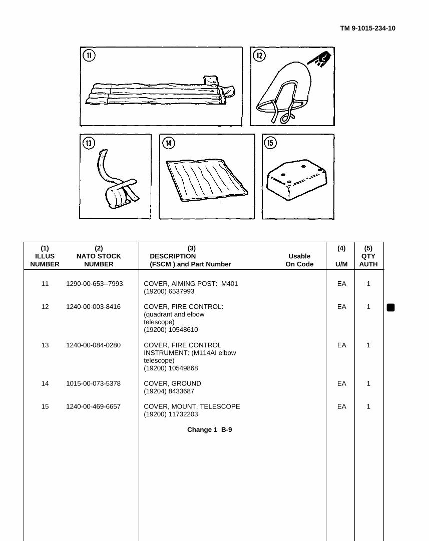
TM 9-1015-234-10
(1) (2) (3) (4) (5)ILLUS NATO STOCK DESCRIPTION Usable QTY
NUMBER NUMBER (FSCM ) and Part Number On Code U/M AUTH
11 1290-00-653--7993 COVER, AIMING POST: M401 EA 1(19200) 6537993
12 1240-00-003-8416 COVER, FIRE CONTROL: EA 1(quadrant and elbowtelescope)(19200) 10548610
13 1240-00-084-0280 COVER, FIRE CONTROL EA 1INSTRUMENT: (M114AI elbowtelescope)(19200) 10549868
14 1015-00-073-5378 COVER, GROUND EA 1(19204) 8433687
15 1240-00-469-6657 COVER, MOUNT, TELESCOPE EA 1(19200) 11732203
Change 1 B-9
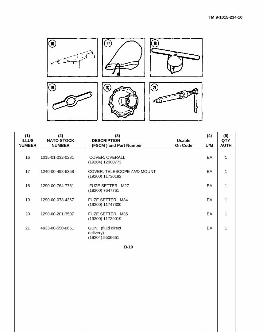
TM 9-1015-234-10
(1) (2) (3) (4) (5)ILLUS NATO STOCK DESCRIPTION Usable QTY
NUMBER NUMBER (FSCM ) and Part Number On Code U/M AUTH
16 1015-01-032-0281 COVER, OVERALL EA 1(19204) 12000773
17 1240-00-498-6358 COVER, TELESCOPE AND MOUNT EA 1(19200) 11730192
18 1290-00-764-7761 FUZE SETTER: M27 EA 1(19200) 7647761
19 1290-00-078-4367 FUZE SETTER: M34 EA 1(19200) 11747300
20 1290-00-201-3507 FUZE SETTER: M35 EA 1(19200) 11729019
21 4933-00-550-6661 GUN: (fluid direct EA 1delivery)(19204) 5506661
B-10
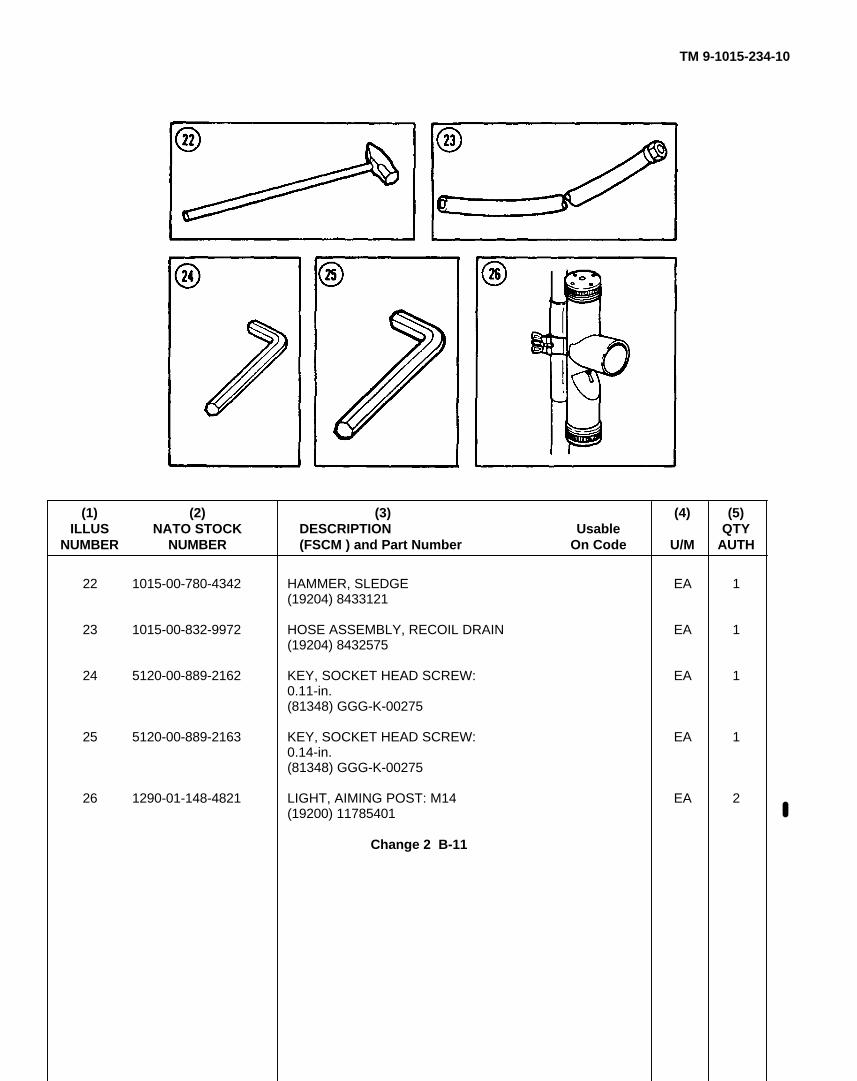
TM 9-1015-234-10
(1) (2) (3) (4) (5)ILLUS NATO STOCK DESCRIPTION Usable QTY
NUMBER NUMBER (FSCM ) and Part Number On Code U/M AUTH
22 1015-00-780-4342 HAMMER, SLEDGE EA 1(19204) 8433121
23 1015-00-832-9972 HOSE ASSEMBLY, RECOIL DRAIN EA 1(19204) 8432575
24 5120-00-889-2162 KEY, SOCKET HEAD SCREW: EA 10.11-in.(81348) GGG-K-00275
25 5120-00-889-2163 KEY, SOCKET HEAD SCREW: EA 10.14-in.(81348) GGG-K-00275
26 1290-01-148-4821 LIGHT, AIMING POST: M14 EA 2(19200) 11785401
Change 2 B-11
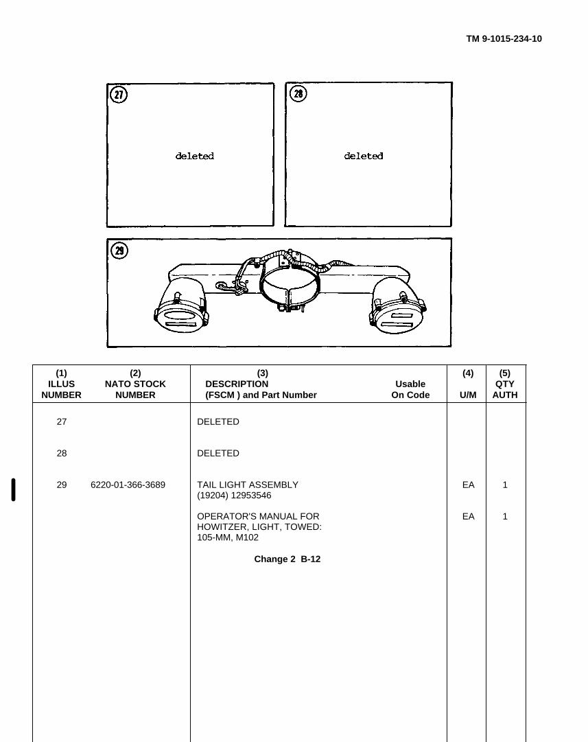
TM 9-1015-234-10
(1) (2) (3) (4) (5)ILLUS NATO STOCK DESCRIPTION Usable QTY
NUMBER NUMBER (FSCM ) and Part Number On Code U/M AUTH
27 DELETED
28 DELETED
29 6220-01-366-3689 TAIL LIGHT ASSEMBLY EA 1(19204) 12953546
OPERATOR'S MANUAL FOR EA 1HOWITZER, LIGHT, TOWED:105-MM, M102
Change 2 B-12
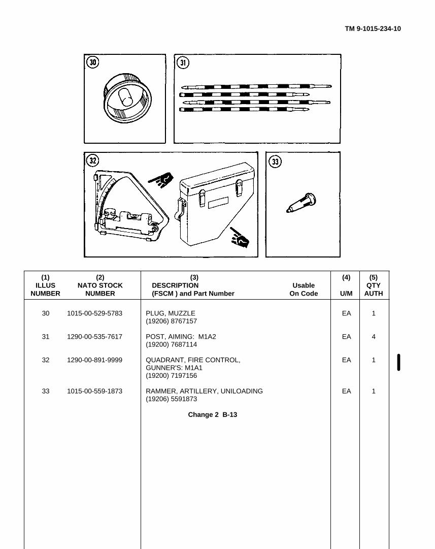
TM 9-1015-234-10
(1) (2) (3) (4) (5)ILLUS NATO STOCK DESCRIPTION Usable QTY
NUMBER NUMBER (FSCM ) and Part Number On Code U/M AUTH
30 1015-00-529-5783 PLUG, MUZZLE EA 1(19206) 8767157
31 1290-00-535-7617 POST, AIMING: M1A2 EA 4(19200) 7687114
32 1290-00-891-9999 QUADRANT, FIRE CONTROL, EA 1GUNNER'S: M1A1(19200) 7197156
33 1015-00-559-1873 RAMMER, ARTILLERY, UNILOADING EA 1(19206) 5591873
Change 2 B-13
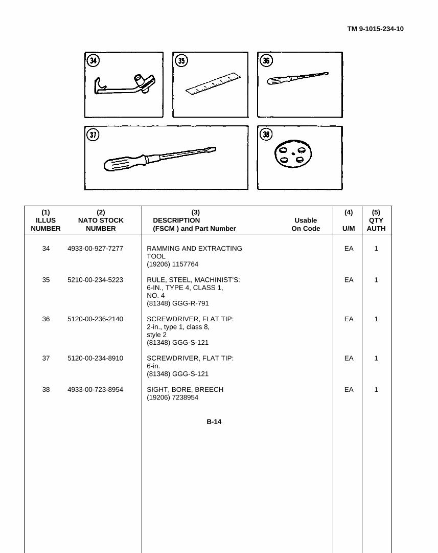
TM 9-1015-234-10
(1) (2) (3) (4) (5)ILLUS NATO STOCK DESCRIPTION Usable QTY
NUMBER NUMBER (FSCM ) and Part Number On Code U/M AUTH
34 4933-00-927-7277 RAMMING AND EXTRACTING EA 1TOOL(19206) 1157764
35 5210-00-234-5223 RULE, STEEL, MACHINIST’S: EA 16-IN., TYPE 4, CLASS 1,NO. 4(81348) GGG-R-791
36 5120-00-236-2140 SCREWDRIVER, FLAT TIP: EA 12-in., type 1, class 8,style 2(81348) GGG-S-121
37 5120-00-234-8910 SCREWDRIVER, FLAT TIP: EA 16-in.(81348) GGG-S-121
38 4933-00-723-8954 SIGHT, BORE, BREECH EA 1(19206) 7238954
B-14
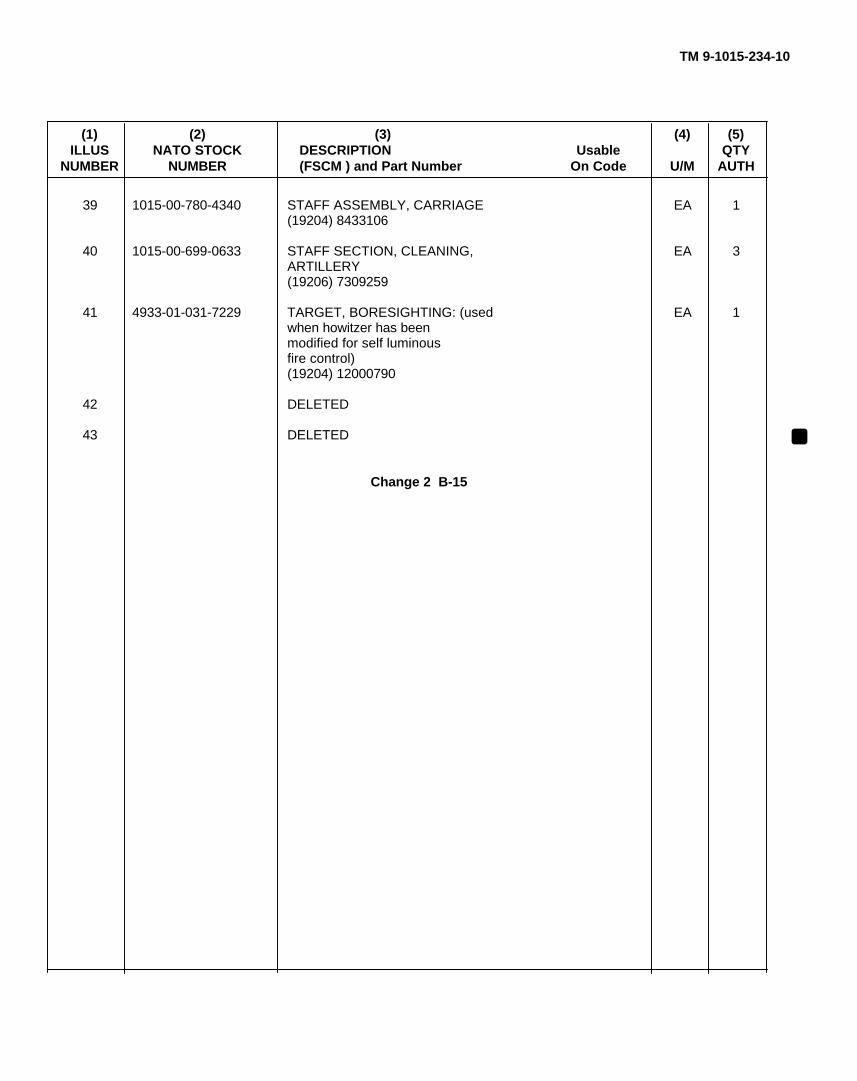
TM 9-1015-234-10
(1) (2) (3) (4) (5)ILLUS NATO STOCK DESCRIPTION Usable QTY
NUMBER NUMBER (FSCM ) and Part Number On Code U/M AUTH
39 1015-00-780-4340 STAFF ASSEMBLY, CARRIAGE EA 1(19204) 8433106
40 1015-00-699-0633 STAFF SECTION, CLEANING, EA 3ARTILLERY(19206) 7309259
41 4933-01-031-7229 TARGET, BORESIGHTING: (used EA 1when howitzer has beenmodified for self luminousfire control)(19204) 12000790
42 DELETED
43 DELETED
Change 2 B-15
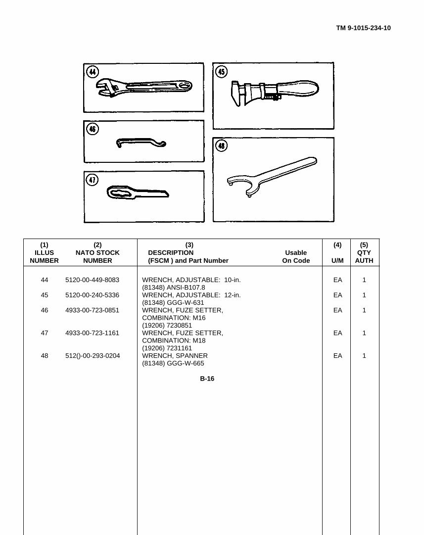
TM 9-1015-234-10
(1) (2) (3) (4) (5)ILLUS NATO STOCK DESCRIPTION Usable QTY
NUMBER NUMBER (FSCM ) and Part Number On Code U/M AUTH
44 5120-00-449-8083 WRENCH, ADJUSTABLE: 10-in. EA 1(81348) ANSI-B107.8
45 5120-00-240-5336 WRENCH, ADJUSTABLE: 12-in. EA 1(81348) GGG-W-631
46 4933-00-723-0851 WRENCH, FUZE SETTER, EA 1COMBINATION: M16(19206) 7230851
47 4933-00-723-1161 WRENCH, FUZE SETTER, EA 1COMBINATION: M18(19206) 7231161
48 512()-00-293-0204 WRENCH, SPANNER EA 1(81348) GGG-W-665
B-16
TM 9-1015-234-10
APPENDIX CADDITIONAL AUTHORIZATION LIST
Section I. INTRODUCTION
C-1. SCOPE
This appendix lists additional items you are authorized for the support of the M102 howitzer.
C-2. GENERAL
This list identifies items that do not have to accompany the M102 howitzer and that do not have to be turned in with it.These items are all authorized to you by CTA, MTOE, TDA, or JTA.
C-3. EXPLANATION OF LISTING
National stock numbers, descriptions, and quantities are provided to help you identify and request the additional items yourequire to support this equipment. The items are listed in alphabetical sequence by item name under the type of document(i.e., CTA, MTOE, TDA, or JTA) which authorizes the item(s) to you.
C-1
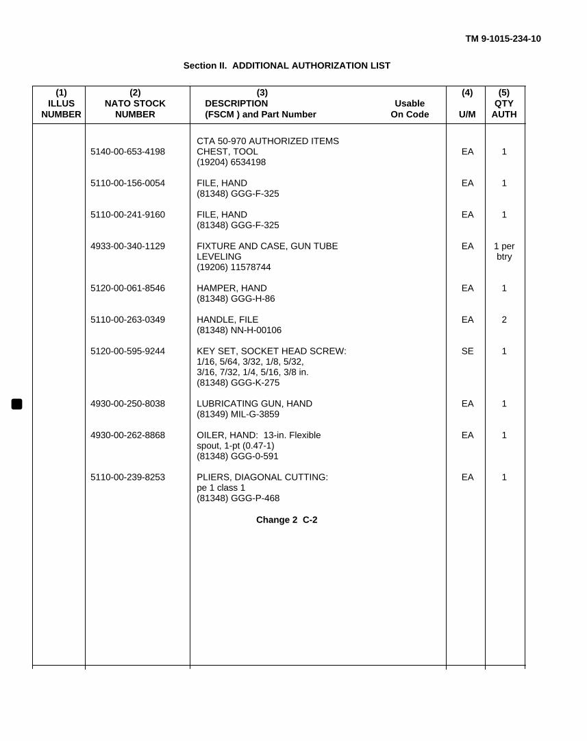
TM 9-1015-234-10
Section II. ADDITIONAL AUTHORIZATION LIST
(1) (2) (3) (4) (5)ILLUS NATO STOCK DESCRIPTION Usable QTY
NUMBER NUMBER (FSCM ) and Part Number On Code U/M AUTH
CTA 50-970 AUTHORIZED ITEMS5140-00-653-4198 CHEST, TOOL EA 1
(19204) 6534198
5110-00-156-0054 FILE, HAND EA 1(81348) GGG-F-325
5110-00-241-9160 FILE, HAND EA 1(81348) GGG-F-325
4933-00-340-1129 FIXTURE AND CASE, GUN TUBE EA 1 perLEVELING btry(19206) 11578744
5120-00-061-8546 HAMPER, HAND EA 1(81348) GGG-H-86
5110-00-263-0349 HANDLE, FILE EA 2(81348) NN-H-00106
5120-00-595-9244 KEY SET, SOCKET HEAD SCREW: SE 11/16, 5/64, 3/32, 1/8, 5/32,3/16, 7/32, 1/4, 5/16, 3/8 in.(81348) GGG-K-275
4930-00-250-8038 LUBRICATING GUN, HAND EA 1(81349) MIL-G-3859
4930-00-262-8868 OILER, HAND: 13-in. Flexible EA 1spout, 1-pt (0.47-1)(81348) GGG-0-591
5110-00-239-8253 PLIERS, DIAGONAL CUTTING: EA 1pe 1 class 1(81348) GGG-P-468
Change 2 C-2
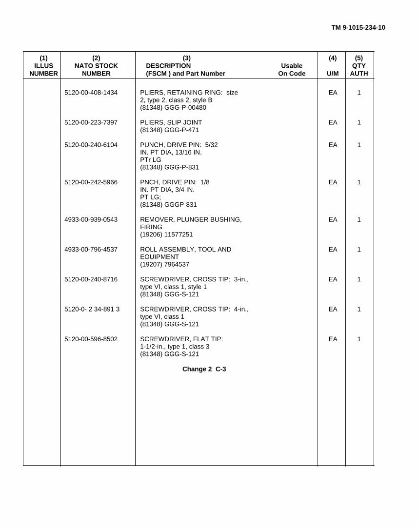
TM 9-1015-234-10
(1) (2) (3) (4) (5)ILLUS NATO STOCK DESCRIPTION Usable QTY
NUMBER NUMBER (FSCM ) and Part Number On Code U/M AUTH
5120-00-408-1434 PLIERS, RETAINING RING: size EA 12, type 2, class 2, style B(81348) GGG-P-00480
5120-00-223-7397 PLIERS, SLIP JOINT EA 1(81348) GGG-P-471
5120-00-240-6104 PUNCH, DRIVE PIN: 5/32 EA 1IN. PT DIA, 13/16 IN.PTr LG(81348) GGG-P-831
5120-00-242-5966 PNCH, DRIVE PIN: 1/8 EA 1IN. PT DIA, 3/4 IN.PT LG;(81348) GGGP-831
4933-00-939-0543 REMOVER, PLUNGER BUSHING, EA 1FIRING(19206) 11577251
4933-00-796-4537 ROLL ASSEMBLY, TOOL AND EA 1EOUIPMENT(19207) 7964537
5120-00-240-8716 SCREWDRIVER, CROSS TIP: 3-in., EA 1type VI, class 1, style 1(81348) GGG-S-121
5120-0- 2 34-891 3 SCREWDRIVER, CROSS TIP: 4-in., EA 1type VI, class 1(81348) GGG-S-121
5120-00-596-8502 SCREWDRIVER, FLAT TIP: EA 11-1/2-in., type 1, class 3(81348) GGG-S-121
Change 2 C-3

TM 9-1015-234-10
ADDITIONAL AUTHORIZATION LIST (cont)
(1) (2) (3) (4) (5)ILLUS NATO STOCK DESCRIPTION Usable QTY
NUMBER NUMBER (FSCM ) and Part Number On Code U/M AUTH
5120-00-892-5931 SCREWDRIVER, RATCHET: 3.88-in. EA 1(81348) GGG-S-1408
1015-00-300-7907 STAKE, GUN PLATFORM, 105-MM: EA 415-in. (Required only whenweapon is emplaced on rockyor frozen ground.)(19204) 12000736
6685-00-344-4603 THERMOMETER, SELF- EA 1INDICAT/NG, BIMETALLIC(81349) MIL-T-3618C
6675-00-240-1881 TRIPOD, SURVEYING: (Required EA 2only when aiming post M1series is issued for arcticuse.)(81349) MIL-T-11674
Change 2 C-4
TM 9-1015-234-10
APPENDIX DEXPENDABLE/DURABLE SUPPLIES AND MATERIALS LIST
Section I. INTRODUCTION
D-1. SCOPE
This appendix lists expendable supplies and materials you will need to operate and maintain the M102 howitzer. This listingis for informational purposes only and is not authority to requisition the listed items. These items are authorized to you byCTA 50-970, Expendable/Durable Items (Except Medical, Class V, Repair Parts, and Heraldic Items), or CTA 8-100, ArmyMedical Department Expendable/Durable Items.
D-2. EXPLANATION OF COLUMNS
a. Column (I)--Item number. This number is assigned to the entry in the listing.
b. Column (2)--Level. This column identifies the lowest level of maintenance that requires the listed item.
C.......................................................................................................................................................Operator/Crew
c. Column (3)--National Stock Number. This is the National stock number assigned to the item. Use it to requestor requisition the iteM.
d. Column (4)--Description. Indicates the Federal item name and, if required, a description to identify the item.The last line for each item indicates the Federal Supply Code for Manufacturer (FSCM) in parentheses followed by the partnumber.
e. Column (5)--Unit of Measure (U/M). Indicates the measure used in performing the actual maintenance function.This measure is expressed by a two-character alphabetical abbreviation (e.g., ea, in., pr). If the unit of measure differs fromthe unit of issue, requisition the lowest unit of issue that will satisfy your requirements.
D-1
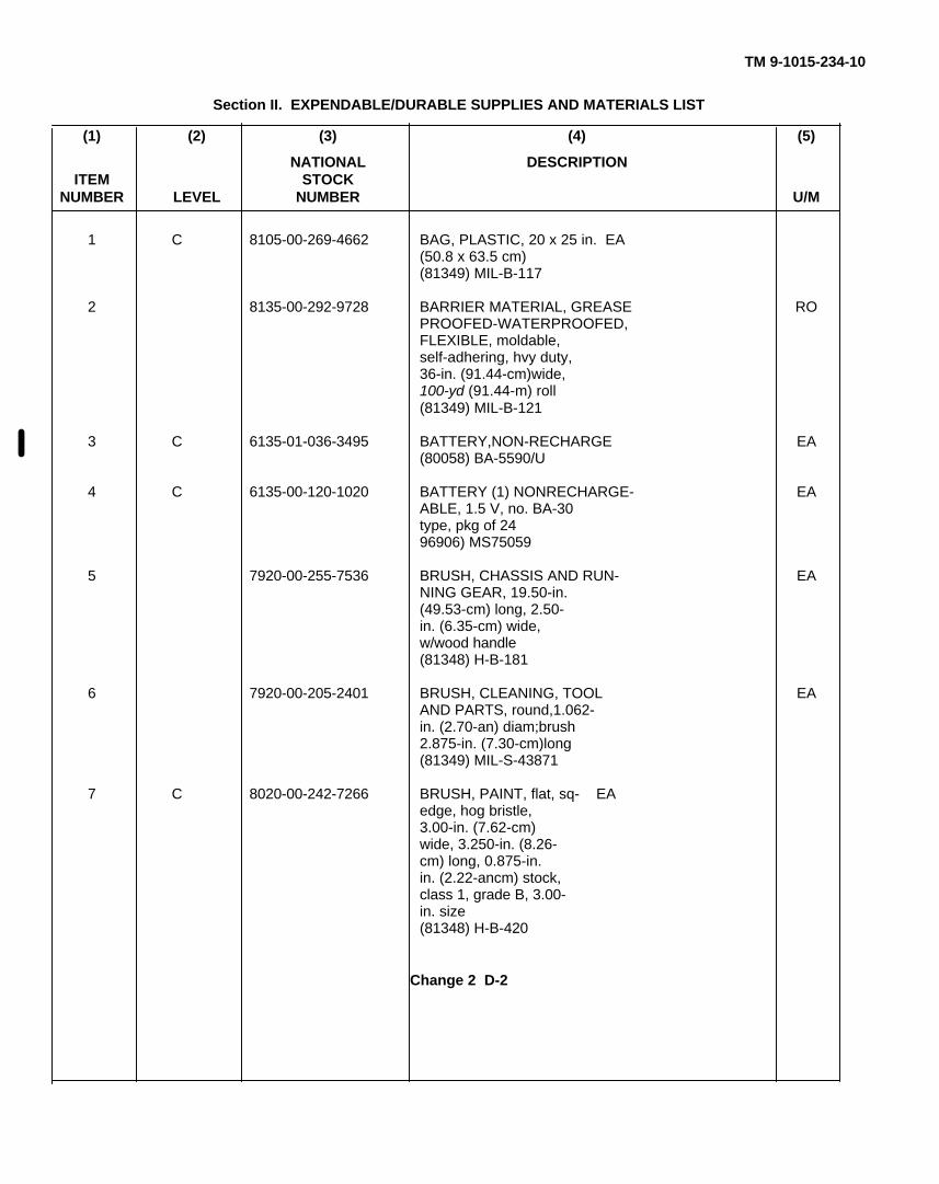
TM 9-1015-234-10
Section II. EXPENDABLE/DURABLE SUPPLIES AND MATERIALS LIST
(1) (2) (3) (4) (5)
NATIONAL DESCRIPTIONITEM STOCK
NUMBER LEVEL NUMBER U/M
1 C 8105-00-269-4662 BAG, PLASTIC, 20 x 25 in. EA(50.8 x 63.5 cm)(81349) MIL-B-117
2 8135-00-292-9728 BARRIER MATERIAL, GREASE ROPROOFED-WATERPROOFED,FLEXIBLE, moldable,self-adhering, hvy duty,36-in. (91.44-cm)wide,100-yd (91.44-m) roll(81349) MIL-B-121
3 C 6135-01-036-3495 BATTERY,NON-RECHARGE EA(80058) BA-5590/U
4 C 6135-00-120-1020 BATTERY (1) NONRECHARGE- EAABLE, 1.5 V, no. BA-30type, pkg of 2496906) MS75059
5 7920-00-255-7536 BRUSH, CHASSIS AND RUN- EANING GEAR, 19.50-in.(49.53-cm) long, 2.50-in. (6.35-cm) wide,w/wood handle(81348) H-B-181
6 7920-00-205-2401 BRUSH, CLEANING, TOOL EAAND PARTS, round,1.062-in. (2.70-an) diam;brush2.875-in. (7.30-cm)long(81349) MIL-S-43871
7 C 8020-00-242-7266 BRUSH, PAINT, flat, sq- EAedge, hog bristle,3.00-in. (7.62-cm)wide, 3.250-in. (8.26-cm) long, 0.875-in.in. (2.22-ancm) stock,class 1, grade B, 3.00-in. size(81348) H-B-420
Change 2 D-2
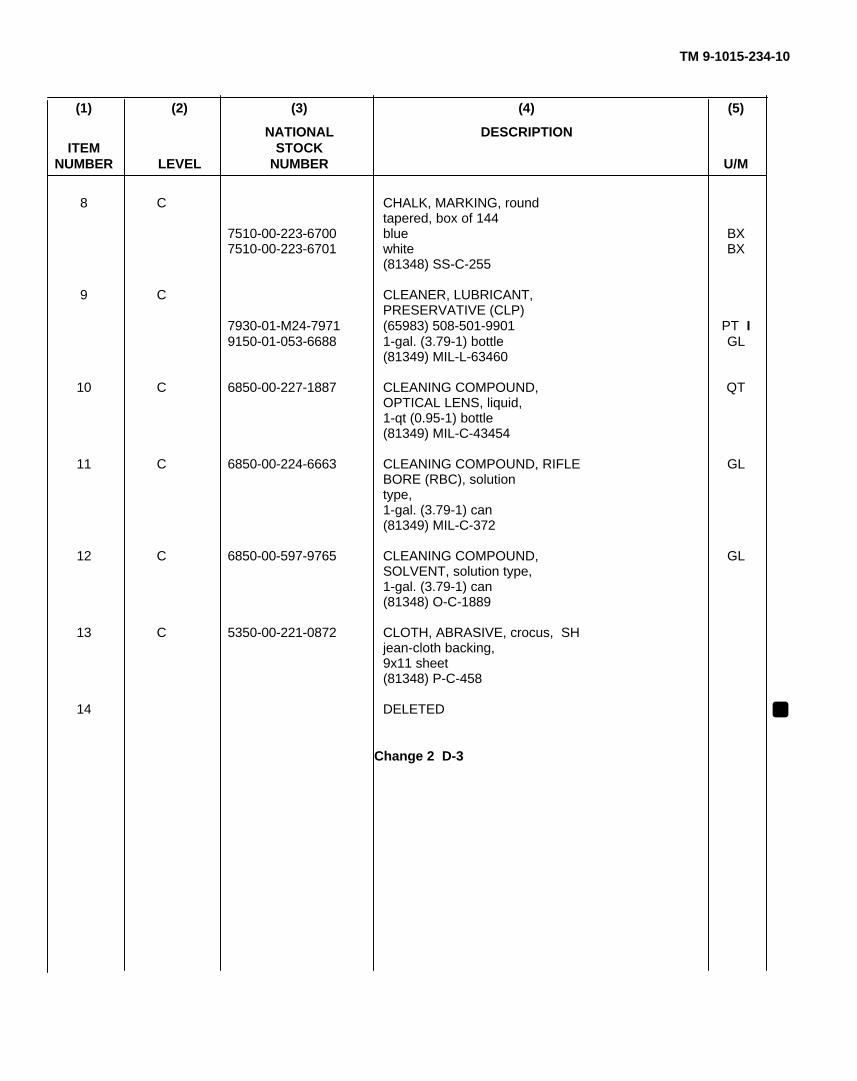
TM 9-1015-234-10
(1) (2) (3) (4) (5)
NATIONAL DESCRIPTIONITEM STOCK
NUMBER LEVEL NUMBER U/M
8 C CHALK, MARKING, roundtapered, box of 144
7510-00-223-6700 blue BX7510-00-223-6701 white BX
(81348) SS-C-255
9 C CLEANER, LUBRICANT,PRESERVATIVE (CLP)
7930-01-M24-7971 (65983) 508-501-9901 PT I9150-01-053-6688 1-gal. (3.79-1) bottle GL
(81349) MIL-L-63460
10 C 6850-00-227-1887 CLEANING COMPOUND, QTOPTICAL LENS, liquid,1-qt (0.95-1) bottle(81349) MIL-C-43454
11 C 6850-00-224-6663 CLEANING COMPOUND, RIFLE GLBORE (RBC), solutiontype,1-gal. (3.79-1) can(81349) MIL-C-372
12 C 6850-00-597-9765 CLEANING COMPOUND, GLSOLVENT, solution type,1-gal. (3.79-1) can(81348) O-C-1889
13 C 5350-00-221-0872 CLOTH, ABRASIVE, crocus, SHjean-cloth backing,9x11 sheet(81348) P-C-458
14 DELETED
Change 2 D-3
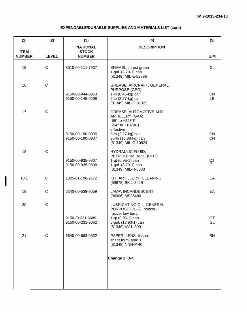
TM 9-1015-234-10
EXPENDABLE/DURABLE SUPPLIES AND MATERIALS LIST (cont)
(1) (2) (3) (4) (5)
NATIONAL DESCRIPTIONITEM STOCK
NUMBER LEVEL NUMBER U/M
15 C 8010-00-111-7937 ENAMEL, forest green GL1-gal. (3.79-1) can(81349) MIL-E-52798
16 C GREASE, AIRCRAFT, GENERALPURPOSE (GPG)
9150-00-944-8953 1-lb (0.45-kg) can CN9150-00-145-0268 5-lb (2.27-kg) can LB
(81349) MIL-G-81322
17 C GREASE, AUTOMOTIVE ANDARTILLERY (GAA),-65° to +225°F(-54° to +1070C)effective
9150-00-190-0905 5-lb (2.27-kg) can CN9150-00-190-0907 35-lb (15.88-kg) can CN
(81349) MIL-G-10924
18 C HYDRAULIC FLUID,PETROLEUM BASE (OHT)
9150-00-935-9807 1-qt (0.95-1) can QT9150-00-935-9808 1-gal. (3.79-1) can GL
(81349) MIL-H-6083
18.1 C 1025-01-196-2172 KIT, ARTILLERY, CLEANING EA(59678) SK 1-84JS
19 C 6240-00-539-9659 LAMP, INCANDESCENT EA(96906) MS35480
20 C LUBRICATING OIL, GENERALPURPOSE (PL-S), noncor-rosive, low temp
9150-{0-231-6689 1-qt (0.95-1) can QT9150-00-231-9062 5-gal. (18.93-1) can GL
(81348) VV-L-800
21 C 6640-00-663-0832 PAPER, LENS, tissue, SHsheet form, type 1(81348) NNN-P-40
Change 1 D-4
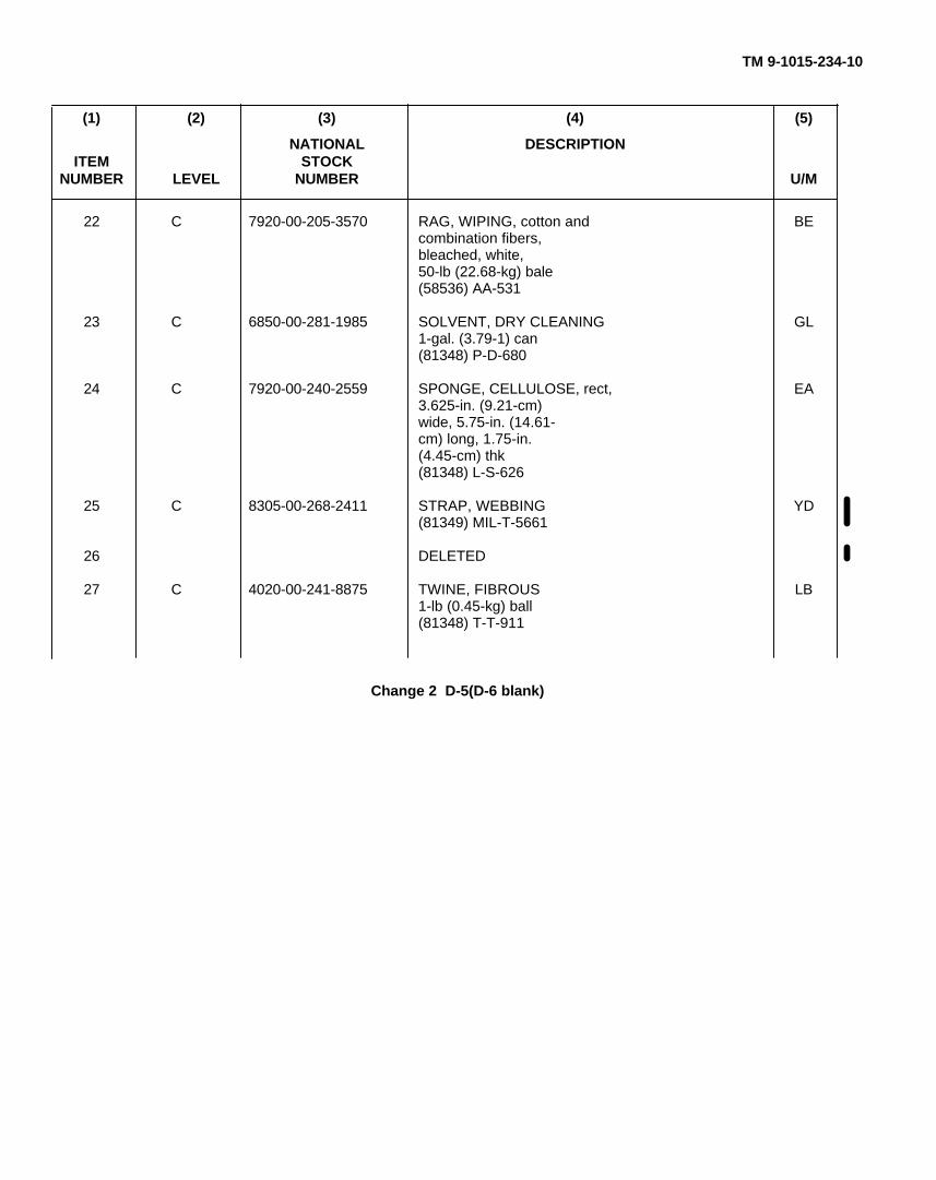
TM 9-1015-234-10
(1) (2) (3) (4) (5)
NATIONAL DESCRIPTIONITEM STOCK
NUMBER LEVEL NUMBER U/M
22 C 7920-00-205-3570 RAG, WIPING, cotton and BEcombination fibers,bleached, white,50-lb (22.68-kg) bale(58536) AA-531
23 C 6850-00-281-1985 SOLVENT, DRY CLEANING GL1-gal. (3.79-1) can(81348) P-D-680
24 C 7920-00-240-2559 SPONGE, CELLULOSE, rect, EA3.625-in. (9.21-cm)wide, 5.75-in. (14.61-cm) long, 1.75-in.(4.45-cm) thk(81348) L-S-626
25 C 8305-00-268-2411 STRAP, WEBBING YD(81349) MIL-T-5661
26 DELETED
27 C 4020-00-241-8875 TWINE, FIBROUS LB1-lb (0.45-kg) ball(81348) T-T-911
Change 2 D-5(D-6 blank)
TM 9-1015-234-10
APPENDIX ESTOWAGE AND SIGN GUIDE (FOR COMPONENTS OF END ITEM,
BASIC ISSUE ITEMS, AND APPLICABLE ADDITIONAL AUTHORIZATIONLIST ITEMS)
E-1. SCOPE
This appendix shows the locations for stowage of equipment and materiel required to be carried on the M102 howitzer.
E-2. GENERAL
Locations of mounted and stowed components of end item are shown on pages 1-8 and 1-9. Basic issue items mounted orstowed on the M102 howitzer are shown in this appendix. Other basic issue items are stowed in the prime mover. Additionalauthorization list items are stowed at the discretion of the chief of section.
E-1
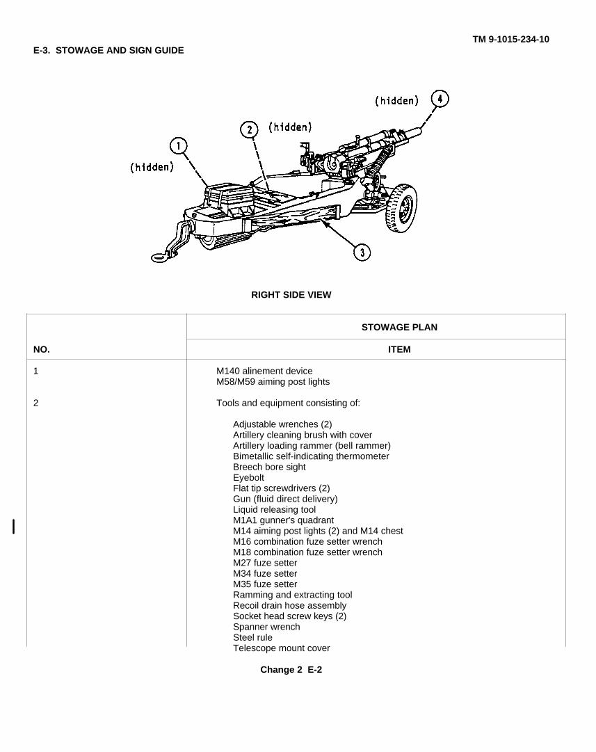
TM 9-1015-234-10E-3. STOWAGE AND SIGN GUIDE
RIGHT SIDE VIEW
STOWAGE PLAN
NO. ITEM
1 M140 alinement deviceM58/M59 aiming post lights
2 Tools and equipment consisting of:
Adjustable wrenches (2)Artillery cleaning brush with coverArtillery loading rammer (bell rammer)Bimetallic self-indicating thermometerBreech bore sightEyeboltFlat tip screwdrivers (2)Gun (fluid direct delivery)Liquid releasing toolM1A1 gunner's quadrantM14 aiming post lights (2) and M14 chestM16 combination fuze setter wrenchM18 combination fuze setter wrenchM27 fuze setterM34 fuze setterM35 fuze setterRamming and extracting toolRecoil drain hose assemblySocket head screw keys (2)Spanner wrenchSteel ruleTelescope mount cover
Change 2 E-2
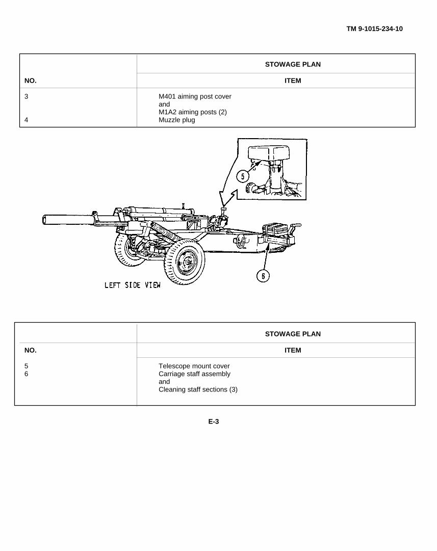
TM 9-1015-234-10
STOWAGE PLAN
NO. ITEM
3 M401 aiming post coverandM1A2 aiming posts (2)
4 Muzzle plug
STOWAGE PLAN
NO. ITEM
5 Telescope mount cover6 Carriage staff assembly
andCleaning staff sections (3)
E-3
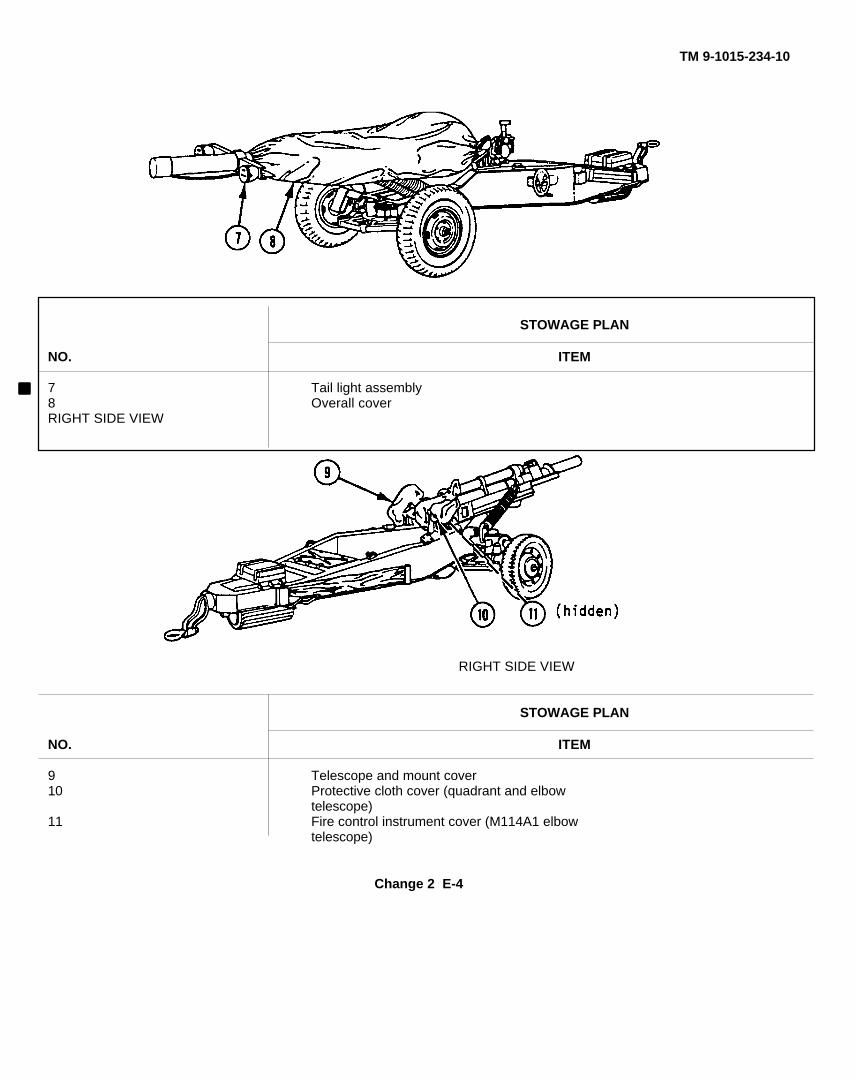
TM 9-1015-234-10
STOWAGE PLAN
NO. ITEM
7 Tail light assembly8 Overall coverRIGHT SIDE VIEW
RIGHT SIDE VIEW
STOWAGE PLAN
NO. ITEM
9 Telescope and mount cover10 Protective cloth cover (quadrant and elbow
telescope)11 Fire control instrument cover (M114A1 elbow
telescope)
Change 2 E-4
TM 9-1015-234-10
ALPHABETICAL INDEX
SubjectPage
A
Abbreviations, list of .................................................................................................................................................. 1-4Additional authorization list ........................................................................................................................................ C-1Aiming circle, M2/M2A2 (See M2/M2A2
aiming circle.)Aiming posts, M1A2 (See M1A2 aimingposts.)Air-lift, preparation of M102 howitzer for ..................................................................................................................... 2-85Alinement device, M140 (See M140
alinement device.)Alinement tests and measurements, fire
control:General.......................................................................................................................................................... 3-41Preparation for .............................................................................................................................................. 3-42
Ammunition forms and records ................................................................................................................................... 4-31
Ammunition, maintenance of ...................................................................................................................................... 4-31
Ammunition prepared for firing butnot fired.......................................................................................................................................................... 4-30
Artillery cleaning brush maintenance .......................................................................................................................... 3-41
Authorized fuzes for M102 howitzer ............................................................................................................................ 4-6
Authorized 105-mm projectiles and use ...................................................................................................................... 4-3
Auxiliary equipment, maintenance of .......................................................................................................................... 3-41
Azimuth walk-off check............................................................................................................................................... 3-54
Index 1

TM 9-1015-234-10
Subject Page
B
Basic issue items........................................................................................................................................................ B-7
Basic issue items, stowage and signguide for......................................................................................................................................................... E-1
Biological decontamination procedures....................................................................................................................... 2-92
Boresighting M113A1 pantel:Using distant aiming point method.................................................................................................................. 2-47Using test target method ................................................................................................................................ 2-51Using the M140 alinement device * ................................................................................................................ 2-44
Boresighting the M114A1 telescope:Using distant aiming point method.................................................................................................................. 2-50Using test target method ................................................................................................................................ 2-51
Breechblock:Disassembly/assembly of .............................................................................................................................. 3-34Installation into breech ring assembly............................................................................................................. 3-34Removal from breech ring assembly .............................................................................................................. 3-29
Breech mechanism assembly:Maintenance ................................................................................................................................................. 3-29Servicing........................................................................................................................................................ 3-29
Breech ring assembly:Installation of breechblock into ...................................................................................................................... 3-34Removal of breechblock from ........................................................................................................................ 3-29
Brush, artillery cleaning, maintenance ....................................................................................................................... 3-41
C
Cannon, M137A1 (See M137A1 cannon.)Cannon tube, leveling the:General ...................................................................................................................................................................... 3-54Using the cannon tube quadrant seats ........................................................................................................................ 3-55Using the gun tube leveling fixture ............................................................................................................................. 3-56
Change 2 Index 2
TM 9-1015-234-10
Subject Page
Cannon tube quadrant seats, leveling thecannon tube using the .................................................................................................................................... 3-55
Carriage, M31 (See M31 carriage.)Cartridge case, primer, and propelling
charge............................................................................................................................................................ 4-14Charge, preparing propelling....................................................................................................................................... 4-28Charge, propelling ...................................................................................................................................................... 4-14Check, azimuth walk-off ............................................................................................................................................. 3-54Checkfire procedures.................................................................................................................................................. 2-75Checking reliability of deflections................................................................................................................................ 3-52Checking reliability of special corrections.................................................................................................................... 3-53Checks and services, preventive
maintenance (PMCS) .................................................................................................................................... 2-10Chemical decontamination procedures ....................................................................................................................... 2-92Cold weather conditions, operation in extreme............................................................................................................ 2-87Collimator (See M1A1 collimator.)Comparison test, M140 alinement device ................................................................................................................... 3-60Components, location and description
of major ......................................................................................................................................................... 1-8Components of end item............................................................................................................................................. B-3Components of end item and basic
issue items lists.............................................................................................................................................. B-1Components of end item, stowage and
sign guide for ................................................................................................................................................. E-1Controls and indicators, description
and use of operator's...................................................................................................................................... 2-1
Change 2 Index 3
TM 9-1015-234-10
Subject Page
CCorrections, checking reliability
of special ....................................................................................................................................................... 3-53Crank assembly maintenance..................................................................................................................................... 3-37Crank, servicing.......................................................................................................................................................... 3-37Crew drill, reduced ..................................................................................................................................................... 1-27Cross-reference list, nomenclature ............................................................................................................................. 1-4
DDamp atmosphere, operation in.................................................................................................................................. 2-89Data plates, M102 howitzer......................................................................................................................................... 1-14Decontamination procedures, nuclear,
biological, and chemical (NBC) ...................................................................................................................... 2-92Deflections, checking reliability of .............................................................................................................................. 3-52Direct fire missions, laying for direction
and elevation during....................................................................................................................................... 2-63Disassembly/assembly of breechblock........................................................................................................................ 3-34Disconnecting M102 howitzer from
prime mover................................................................................................................................................... 2-27Distant aiming point method:
Boresighting M113A1 pantel using ................................................................................................................ 2-47Boresighting M114A1 telescope using *.......................................................................................................... 2-50
Draining oil reserve..................................................................................................................................................... 3-38Drill:Reduced crew............................................................................................................................................................. 1-27Section . ..................................................................................................................................................................... 1-21Duds ...................................................................................................................................................................... 4-30
Index 4
TM 9-1015-234-10
Subject PageE
Emplacing M1A2 aiming posts.................................................................................................................................... 2-41Emplacing M1A1 collimator ........................................................................................................................................ 2-38 IEmplacing M102 howitzer........................................................................................................................................... 2-29End-for-end test, M1A1 gunner's
quadrant......................................................................................................................................................... 3-44End item, components of ............................................................................................................................................ B-3Equipment characteristics, capabilities,
and features................................................................................................................................................... 1-6Equipment data .......................................................................................................................................................... 1-12Equipment description ............................................................................................................................................... 1-6Equipment improvement recommendations(EIR's), reporting......................................................................................................................................................... 1-3Equivalent service rounds........................................................................................................................................... 4-14Errors, reporting and recommending
improvements ................................................................................................................................................ iExcessive pressure in M137A1 cannon....................................................................................................................... 4-29Expendable/durable supplies and
materials list................................................................................................................................................... D-1
Explanation of columns .............................................................................................................................................. B-1D-1
Explanation of listing .................................................................................................................................................. C-1Extreme cold weather conditions, operation in ............................................................................................................ 2-87Extreme hot weather conditions, operation in.............................................................................................................. 2-88
Filling oil reserve ........................................................................................................................................................ 3-39
Change 2 Index 5
TM 9-1015-234-10
Subject Page
FFire control alinement tests and
measurements ............................................................................................................................................... 3-41Fire control alinement tests,
preparation for................................................................................................................................................ 3-42Firing, preparation for ................................................................................................................................................. 4-14Firing tables................................................................................................................................................................ 4-30Firing the M102 howitzer ............................................................................................................................................ 2-70Fixture, gun tube leveling, leveling
the cannon tube using .................................................................................................................................... 3-56Fording and swimming operations .............................................................................................................................. 2-91Forms and records, ammunition ................................................................................................................................. 4-31Forms and records, maintenance................................................................................................................................ 1-3Fuze setting procedures for the
M102 howitzer................................................................................................................................................ 4-19Fuzes for M102 howitzer, authorized ......................................................................................................................... 4-6Fuzing ...................................................................................................................................................................... 4-17
GGlossary .................................................................................................................................................................... 1-6Gunner's quadrant, M1A1 (See
M1Al gunner's quadrant.)Gun tube leveling fixture, leveling the
cannon tube using.......................................................................................................................................... 3-56
HHand receipt (-HR) manuals ....................................................................................................................................... 1-3
Change 2 Index 6
TM 9-1015-234-10
Subject Page
Hot, damp, and salty atmosphere,operation in ...................................................................................................................................................... 2-89
Hot weather conditions, operation in extreme........................................................................................................ 2-88
Howitzer (See M102 howitzer.)
I
Indicators, description and useof operator's controls and ................................................................................................................................... 2-1
Indirect fire missions, laying fordirection and elevation during........................................................................................................................... 2-59
Inspecting MIA1 collimator .................................................................................................................................... 3-40
Inspecting suspension pin assembly...................................................................................................................... 3-37
Inspection of the M134A1 mount(azimuth walk-off check)................................................................................................................................... 3-54
Installation of breechblock intobreech ring assembly........................................................................................................................................ 3-34
Installing M113A1 pantel ....................................................................................................................................... 2-32
Installing M114A1 telescope.................................................................................................................................. 2-34
Internal transport, preparation of M102
L
Laying for direction:Using M1A2 aiming posts...................................................................................................................................... 2-61Using M1A1 collimator .......................................................................................................................................... 2-60
Laying for direction and elevation:During direct fire missions ..................................................................................................................................... 2-63During indirect fire missions .................................................................................................................................. 2-59
Change 2 Index 7
TM 9-1015-234-10
Subject Page
LLaying for elevation............................................................................................................................................... 2-63
Laying the M102 howitzer using theM2/M2A2 aiming circle ..................................................................................................................................... 2-35
Leveling fixture, leveling thecannon tube using gun tube.............................................................................................................................. 3-56
Leveling the cannon tube:General ............................................................................................................................................................ 3-54Using the cannon tube quadrant seats .............................................................................................................. 3-55Using the gun tube leveling fixture.................................................................................................................... 3-56
Leveling the trunnions:General ............................................................................................................................................................ 3-48Using scribe lines on M14A1 quadrant.............................................................................................................. 3-51Using the plumbline ......................................................................................................................................... 3-48
List of abbreviations ................................................................................................................................................ 1-4
Loading, procedure for (ammunition) .................................................................................................................... 4-29
Loading the M102 howitzer for firing...................................................................................................................... 2-57
Location and description of majorcomponents........................................................................................................................................................ 1-8
Lubrication instructions ........................................................................................................................................... 3-1
M
Maintenance forms and records ............................................................................................................................. 1-3
Maintenance instructions ........................................................................................................................................ 3-1
Maintenance of ammunition .................................................................................................................................. 4-31
Maintenance of auxiliary equipment ...................................................................................................................... 3-41
Maintenance procedures ....................................................................................................................................... 3-29
Change 2 Index 8
TM 9-1015-234-10
Subject Page
Major components, location anddescription of ..................................................................................................................................................... 1-8
March order .......................................................................................................................................................... 2-80
Measurements, fire control alinementtests and........................................................................................................................................................... 3-41
Micrometer test, MIA1 gunner's quadrant .............................................................................................................. 3-42
Misfire/checkfire procedures ................................................................................................................................. 2-75
Modifications and productimprovement package...................................................................................................................................... 1-10
Mount, M134A1 (See M134A1 mount.)
M1A1 collimator, inspecting .................................................................................................................................. 3-40
M1A2 aiming posts:Emplacing ........................................................................................................................................................ 2-41Laying for direction using.................................................................................................................................. 2-61
M1A1 gunner's quadrant:End-for-end test................................................................................................................................................ 3-44Micrometer test ................................................................................................................................................ 3-42
M1A1 collimator,:Emplacing ........................................................................................................................................................ 2-38Laying for direction using.................................................................................................................................. 2-60Maintenance..................................................................................................................................................... 3-40
M102 howitzerAuthorized fuzes for ........................................................................................................................................... 4-6Data plates ..................................................................................................................................................... 1-14Disconnecting from prime mover...................................................................................................................... 2-27Emplacing ....................................................................................................................................................... 2-29Firing ............................................................................................................................................................... 2-70Fuze setting procedures for .............................................................................................................................. 4-19Laying using the M2/M2A2 aiming circle .......................................................................................................... 2-35Loading for firing .............................................................................................................................................. 2-57Preparation for air-lift ....................................................................................................................................... 2-85Preparation for internal transport ...................................................................................................................... 2-85Preparation for towing ..................................................................................................................................... 2-81Unloading......................................................................................................................................................... 2-71
Change 2 Index 9
TM 9-1015-234-10
Subject Page
M
M113A1 pantel, boresighting:Using distant aiming point method.................................................................................................................... 2-47Using test target method 2-51Using the M140 alinement device..................................................................................................................... 2-44
M113A1 pantel, installing 2-32
M114A1 telescope, boresighting:Using distant aiming point method.................................................................................................................... 2-50Using test target method................................................................................................................................... 2-51
M114A1 telescope, installing ................................................................................................................................ 2-34
M114A1 telescope test ......................................................................................................................................... 3-60
M134A1 mount, inspection of the ......................................................................................................................... 3-54Excessive pressure in....................................................................................................................................... 4-29Maintenance..................................................................................................................................................... 3-29Servicing .......................................................................................................................................................... 3-29
M14A1 quadrant, leveling the trunnionsusing scribe lines on ......................................................................................................................................... 3-51
M14A1 quadrant test ............................................................................................................................................. 3-57
M140 alinement device, boresighting
M113A1 pantel using............................................................................................................................................. 2-44
M140 alinement device comparison test................................................................................................................ 3-60
M2/M2A2 aiming circle, laying the
M102 howitzer using ............................................................................................................................................. 2-35Maintenance .................................................................................................................................................... 3-37Servicing ......................................................................................................................................................... 3-37M37/M37A1 recoil mechanism maintenance .................................................................................................... 3-38
Index 10
TM 9-1015-234-10
Subject Page
N
Nomenclature cross-reference list ........................................................................................................................... 1-4
Nuclear, biological, and chemical (NBC)decontamination procedures............................................................................................................................. 2-92
O
Oil reserve:Draining............................................................................................................................................................ 3-38Filling ............................................................................................................................................................... 3-39
Operation in extreme cold weather conditions ....................................................................................................... 2-87
Operation in extreme hot weather conditions......................................................................................................... 2-88
Operation in hot, damp, and saltyatmosphere ...................................................................................................................................................... 2-89
Operation in unusual terrain conditions.................................................................................................................. 2-90
Operation under unusual conditions ...................................................................................................................... 2-87
Operation under usual conditions .......................................................................................................................... 2-27
Operator's controls and indicators,description and use of ........................................................................................................................................ 2-1
P
Packing and unpacking (ammunition).................................................................................................................... 4-16
Pantel, M113A1 (See M113A1 pantel.)
Pin assembly, suspension (See suspensionpin assembly.)
Plates, M102 howitzer data ................................................................................................................................... 1-14
Plumbline, leveling the trunnions using ................................................................................................................. 3-48
PMCS procedures................................................................................................................................................. 2-11
Prefiring checks ................................................................................................................................................... 2-55
Index 11
TM 9-1015-234-10
Subject Page
P
Preparation for fire controlalinement tests ................................................................................................................................................. 3-42
Preparation for firing ............................................................................................................................................. 4-14
Preparation of M102 howitzer for air-lift................................................................................................................. 2-85
Preparation of M102 howitzer for internaltransport........................................................................................................................................................... 2-85
Preparation of M102 howitzer for towing................................................................................................................ 2-81
Preparing propelling charge .................................................................................................................................. 4-28
Pressure in M137A1 cannon, excessive ................................................................................................................ 4-29
Preventive maintenance checks andservices (PMCS) .............................................................................................................................................. 2-10
Primer................................................................................................................................................................... 4-14
Procedure for loading (ammunition) ...................................................................................................................... 4-29
Product improvement package,modifications and ............................................................................................................................................. 1-10
Projectile coloring and marking .............................................................................................................................. 4-1
Projectiles and use, authorized 105-mm ................................................................................................................. 4-3
Propelling charge .................................................................................................................................................. 4-14
Propelling charge, preparing ................................................................................................................................. 4-28
Q
Quadrant, MIAI gunner's (See MlA1 gunner'squadrant.)
Quadrant, M14A1 (See M14A1 quadrant.)
Quadrant seats, leveling the cannontube using the cannon tube............................................................................................................................... 3-55
Change 2 Index 12
TM 9-1015-234-10
Subject Page
R
Rapid traverse....................................................................................................................................................... 2-79
Recoil mechanism, M37/M37A1 (SeeM37/M37A1 recoil mechanism.)
Records, ammunition forms and ........................................................................................................................... 4-31
Records, maintenance forms and ........................................................................................................................... 1-3
Reduced crew drill................................................................................................................................................. 1-27
References .............................................................................................................................................................A-1
Reliability of deflections, checking ........................................................................................................................ 3-52
Reliability of special corrections,checking................................................................................................................................................................ 3-53
Removal of breechblock from breechring assembly........................................................................................................................................................ 3-29
Reporting equipment improvementrecommendations (EIR's) ........................................................................................................................................ 1-3
Reporting errors and recommendingimprovements ............................................................................................................................................................ i
Rounds, equivalent service .................................................................................................................................. 4-14
S
Salty atmosphere, operation in ............................................................................................................................. 2-89
Scope ..................................................................................................................................................................... 1-3
Scribe lines on M14A1 quadrant, levelingthe trunnions using ........................................................................................................................................... 3-51
Seats, leveling the cannon tube usingcannon tube quadrant ...................................................................................................................................... 3-55
Section drill .......................................................................................................................................................... 1-21
Servicing breech mechanism assembly................................................................................................................. 3-29
Index 13

TM 9-1015-234-10
Subject Page
S
Servicing crank ..................................................................................................................................................... 3-37
Servicing M137A1 cannon .................................................................................................................................... 3-29
Servicing M31 carriage ......................................................................................................................................... 3-37
Special corrections, checkingreliability of....................................................................................................................................................... 3-53
Stowage and sign guide for componentsof end item, basic issue items, andapplicable additional authorizationlist items.............................................................................................................................................................E-1
Suspension pin assembly:Inspecting ........................................................................................................................................................ 3-37Maintenance .................................................................................................................................................... 3-37
Swimming operations, fording and ........................................................................................................................ 2-91
T
Tables, firing ........................................................................................................................................................ 4-30
Tail light assembly Maintenance .......................................................................................................................... 3-41
Telescope, M114A1 (See M114A1 telescope.)
Terrain conditions, operation in unusual ................................................................................................................ 2-90
Test:M1A1 gunner's quadrant end-for-end ............................................................................................................... 3-44M1Al gunner's quadrant micrometer ................................................................................................................ 3-42M114A1 telescope ........................................................................................................................................... 3-60M14A1 quadrant .............................................................................................................................................. 3-57M140 alinement device comparison ................................................................................................................ 3-60
Tests and measurements, firecontrol alinement.............................................................................................................................................. 3-41
Change 2 Index 14
TM 9-1015-234-10
Subject Page
Tests, preparation for fire controlalinement ......................................................................................................................................................... 3-42
Test target method, boresighting M113A1pantel and M114A1 telescope using ................................................................................................................ 2-51
To call off ............................................................................................................................................................. 1-22
To change posts ................................................................................................................................................... 1-24
To dismount--prepare for action ........................................................................................................................... 1-26
To fall out--prepare for action ............................................................................................................................... 1-26
To form the section ............................................................................................................................................... 1-21
To mount--march order ......................................................................................................................................... 1-25
To post the section................................................................................................................................................ 1-23
Towing, preparation of M102howitzer for ..................................................................................................................................................... 2-81
Troubleshooting procedures ................................................................................................................................. 3-12
Trunnions, leveling the:General ........................................................................................................................................................... 3-48Using scribe lines on M14A1 quadrant ............................................................................................................. 3-51Using the plumbline.......................................................................................................................................... 3-48
Tube, leveling cannon:General ........................................................................................................................................................... 3-54Using the cannon tube quadrant seats .............................................................................................................. 3-55Using the gun tube leveling fixture ................................................................................................................... 3-56
U
Unloading an unfired round ................................................................................................................................... 2-73
Unloading a spent cartridge whichfailed to extract................................................................................................................................................. 2-72
Unloading a spent (fired) cartridge ....................................................................................................................... 2-71
Unloading the M102 howitzer ............................................................................................................................... 2-71
Index 15
TM 9-1015-234-10
Subject Page
U
Unpacking (ammunition), packing and .................................................................................................................. 4-16
Unusual conditions, operation under ..................................................................................................................... 2-87
Unusual terrain conditions, operation in ................................................................................................................ 2-90
Usual conditions, operation under ........................................................................................................................ 2-27
W
Walk-off check, azimuth ....................................................................................................................................... 3-54
Weather conditions, operation in extreme cold ..................................................................................................... 2-87
Weather conditions, operation in extreme hot ...................................................................................................... 2-88
Index 16
TM 9-1015-234-10
By Order of the Secretary of the Army:
JOHN A. WICKHAM, JR.General, United States Army
Chief of Staff
Official:
DONALD J. DELANDROBrigadier General, United States Army
The Adjutant General
DISTRIBUTION:
To be distributed in accordance with DA Form 12-40, Operator Maintenance requirements for Howitzer, Light,Towed 105-MM, M102.
¶U. S. Government Printing Office. 1996 - 406-421/50010
TM 9-1015-234-10
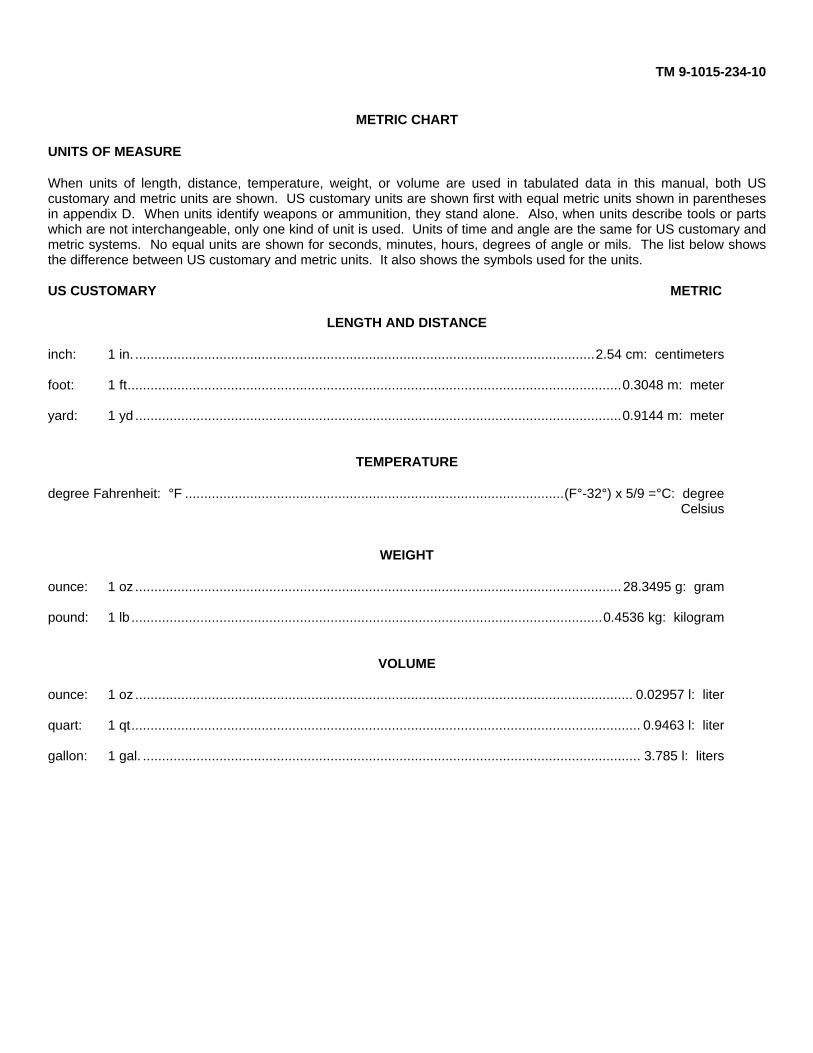
TM 9-1015-234-10
METRIC CHART
UNITS OF MEASURE
When units of length, distance, temperature, weight, or volume are used in tabulated data in this manual, both UScustomary and metric units are shown. US customary units are shown first with equal metric units shown in parenthesesin appendix D. When units identify weapons or ammunition, they stand alone. Also, when units describe tools or partswhich are not interchangeable, only one kind of unit is used. Units of time and angle are the same for US customary andmetric systems. No equal units are shown for seconds, minutes, hours, degrees of angle or mils. The list below showsthe difference between US customary and metric units. It also shows the symbols used for the units.
US CUSTOMARY METRIC
LENGTH AND DISTANCE
inch: 1 in. ........................................................................................................................2.54 cm: centimeters
foot: 1 ft.................................................................................................................................0.3048 m: meter
yard: 1 yd ...............................................................................................................................0.9144 m: meter
TEMPERATURE
degree Fahrenheit: °F ...................................................................................................(F°-32°) x 5/9 =°C: degreeCelsius
WEIGHT
ounce: 1 oz ............................................................................................................................... 28.3495 g: gram
pound: 1 lb ...........................................................................................................................0.4536 kg: kilogram
VOLUME
ounce: 1 oz .................................................................................................................................. 0.02957 l: liter
quart: 1 qt..................................................................................................................................... 0.9463 l: liter
gallon: 1 gal. .................................................................................................................................. 3.785 l: liters

PIN: 043456-000