Embed Size (px)
Citation preview
COBB TUNINGTechnical Documentation
How Mitsubishi’s Factory Boost Control System Works v1.05
This document is intended to assist you with the understanding of how turbo boost pressure is controlled on an internally (or externally) wastegated turbocharger through the factory boost control system. In order for the boost pressure to be properly controlled by the stock boost control system, we must show you how to properly set-up or calibrate your internally or externally wastegated turbocharger. This document is broken down into four chapters; Hardware, Plumbing, Hardware Function, & Mechanical Calibration. Please read the following thoroughly before you attempt to tune your Mitsubishi EVO with the AccessECUTM software. In the AccessECU StreetTUNERTM or ProTUNERTM software, Descriptions and Tuning Tips for most of the tables are provided and can be accessed by pressing the “F1” key while that table is highlighted in the Table List.
We would like to go into further detail about the safeguards and advanced tuning features that are available through the AccessECU software. The boost control system uses a closed-loop targeting system which does everything it can to make the boost control system consistent. By employing this closed-loop boost control system the electronic control unit (ECU) can use its speed to bring down boost in overboost situations and raise the wastegate duty cycles (WGDC) for underboost situations. The stock boost control system is much faster than any human analysis and input; we highly suggest you use it to your advantage. Once the stock boost control system is fully understood you will find it easy to tune on internally or externally wastegated turbos.
Copyright © 2006 Cobb Tuning, Inc. All rights reserved.
TM
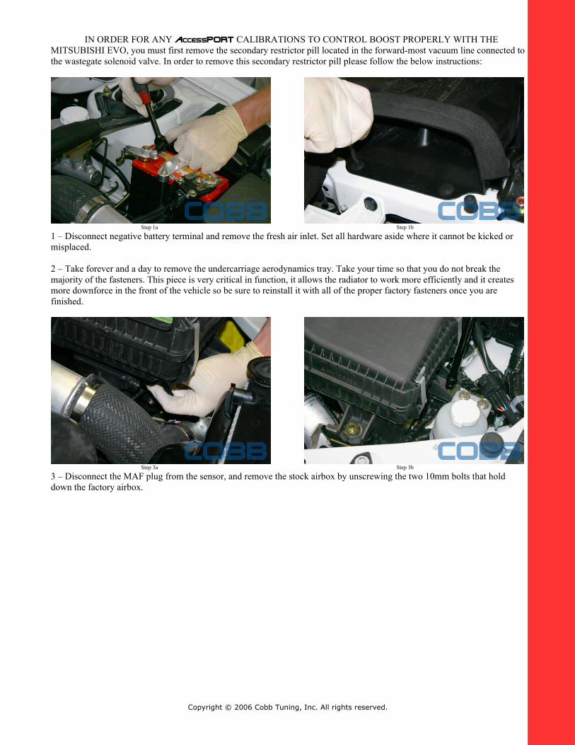
IN ORDER FOR ANY AccessPORT CALIBRATIONS TO CONTROL BOOST PROPERLY WITH THE MITSUBISHI EVO, you must first remove the secondary restrictor pill located in the forward-most vacuum line connected to the wastegate solenoid valve. In order to remove this secondary restrictor pill please follow the below instructions:
Step 1a Step 1b
1 – Disconnect negative battery terminal and remove the fresh air inlet. Set all hardware aside where it cannot be kicked or misplaced.
2 – Take forever and a day to remove the undercarriage aerodynamics tray. Take your time so that you do not break the majority of the fasteners. This piece is very critical in function, it allows the radiator to work more efficiently and it creates more downforce in the front of the vehicle so be sure to reinstall it with all of the proper factory fasteners once you are finished.
Step 3a Step 3b
3 – Disconnect the MAF plug from the sensor, and remove the stock airbox by unscrewing the two 10mm bolts that hold down the factory airbox.
Copyright © 2006 Cobb Tuning, Inc. All rights reserved.
Step 3c
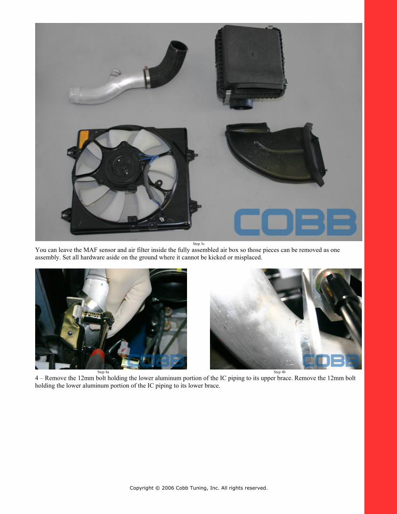
You can leave the MAF sensor and air filter inside the fully assembled air box so those pieces can be removed as one assembly. Set all hardware aside on the ground where it cannot be kicked or misplaced.
Step 4a Step 4b
4 – Remove the 12mm bolt holding the lower aluminum portion of the IC piping to its upper brace. Remove the 12mm bolt holding the lower aluminum portion of the IC piping to its lower brace.
Copyright © 2006 Cobb Tuning, Inc. All rights reserved.
Step 4c
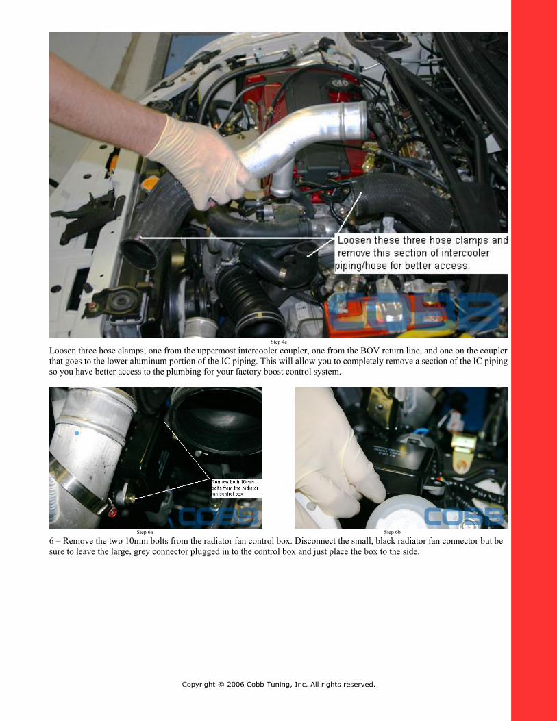
Loosen three hose clamps; one from the uppermost intercooler coupler, one from the BOV return line, and one on the coupler that goes to the lower aluminum portion of the IC piping. This will allow you to completely remove a section of the IC piping so you have better access to the plumbing for your factory boost control system.
Step 6a Step 6b
6 – Remove the two 10mm bolts from the radiator fan control box. Disconnect the small, black radiator fan connector but be sure to leave the large, grey connector plugged in to the control box and just place the box to the side.
Copyright © 2006 Cobb Tuning, Inc. All rights reserved.
Step 7a Step 7b
Step 7c
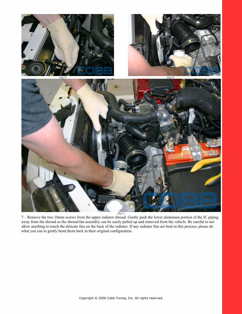
7 – Remove the two 10mm screws from the upper radiator shroud. Gently push the lower aluminum portion of the IC piping away from the shroud so the shroud/fan assembly can be easily pulled up and removed from the vehicle. Be careful to not allow anything to touch the delicate fins on the back of the radiator. If any radiator fins are bent in this process, please do what you can to gently bend them back in their original configuration.
Copyright © 2006 Cobb Tuning, Inc. All rights reserved.

Step 8a
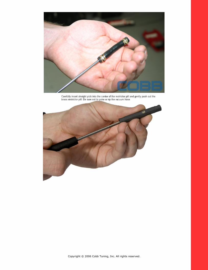
8 – Remove the vacuum line that is attached to the forward-most nipple on the wastegate solenoid valve. The secondary restrictor pill is located inside this vacuum line close to the end that is attached to the wastegate solenoid valve. This secondary restrictor pill must be removed from the boost control system in order for ANY AccessPORT calibration to properly control boost on the Mitsubishi EVO. The easiest way we have found to remove the secondary restrictor pill is to squirt some silicon spray into the end of the hose which contains the secondary restrictor pill. You can then squeeze out the pill with your fingers or use a pick to work it out of the hose. Another option is to completely replace this vacuum line with a new, similarly-sized silicon line that has no restrictor pill inside.
Please install all items in the reverse order they were removed. Be very careful when setting the radiator shroud/fan assembly back into place, the fins on the radiator are very delicate and can bend very easily. If any fins are bent in the installation process, please do what you can to bend them back in their original configuration.
You must remove this secondary restrictor pill in order for any AccessPORT calibration to control boost properly on your Mitsubishi EVO.
Copyright © 2006 Cobb Tuning, Inc. All rights reserved.
Chapter 1 – Hardware
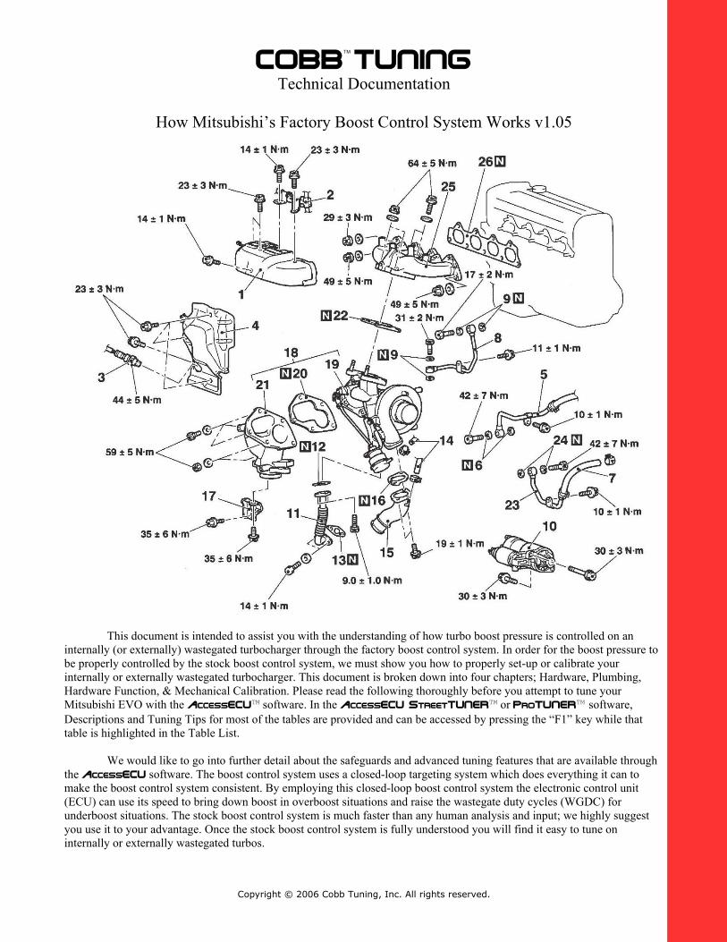
Turbo - An exhaust driven air compressor which consists of four basic sections or components. The compressor section consists of the compressor housing and the compressor wheel. This section acts as the inlet or intake for the turbo, compressing the intake charge and generating relative pressure (boost). Generally speaking the inlet is always in a vacuum, sucking air in and the outlet is pressurized with the intake charge. Next is the center section which contains the bearings, shaft, and the oil and anti-freeze passage ways; the compressor and turbine wheels are also attached to the shaft in this section. The third section is the turbine section which consists of the turbine wheel and turbine housing. This section also contains a machined by-pass for the wastegate valve to seat against. The last component of a turbo charger is the wastegate valve and wastegate actuator which control the wastegate valve’s movement. We highly recommend that you use a turbocharger which has both an oil and water cooled center section; turbocharger longevity is compromised when only oil is used to cool the turbocharger center housing.
Wastegate Actuator - A spring/diaphragm based mechanism which controls the movement of the wastegate valve. A turbo wastegate is normally closed, forced shut by a compressed spring inside the actuator canister. As pressure is applied to the nipple of the canister, the wastegate shaft moves away from the actuator, swinging open the wastegate valve.
Wastegate Solenoid Valve - An electromagnetic solenoid which controls the air flow from the wastegate actuator to the turbo inlet. This device is normally closed when no voltage is applied. When 12V direct current (DC) voltage is applied, by the drivers in the electronic control module (ECM), to the wastegate solenoid valve, it fully opens allowing air to pass through the device. A 0% Wastegate Duty Cycle (WGDC) setting will allow the solenoid to stay fully closed; which will force the turbo to run mechanical boost pressure. A 100% WGDC setting will force the solenoid to stay fully open; which will force the turbo to run maximum boost pressure.
Vacuum Lines - Rubberized or silicone tubes attached to various components in the engine assembly. For this article we will be concerned with the eight attachment points and the four sections of vacuum line plumbing and adapters which we will cover in Chapter 2.
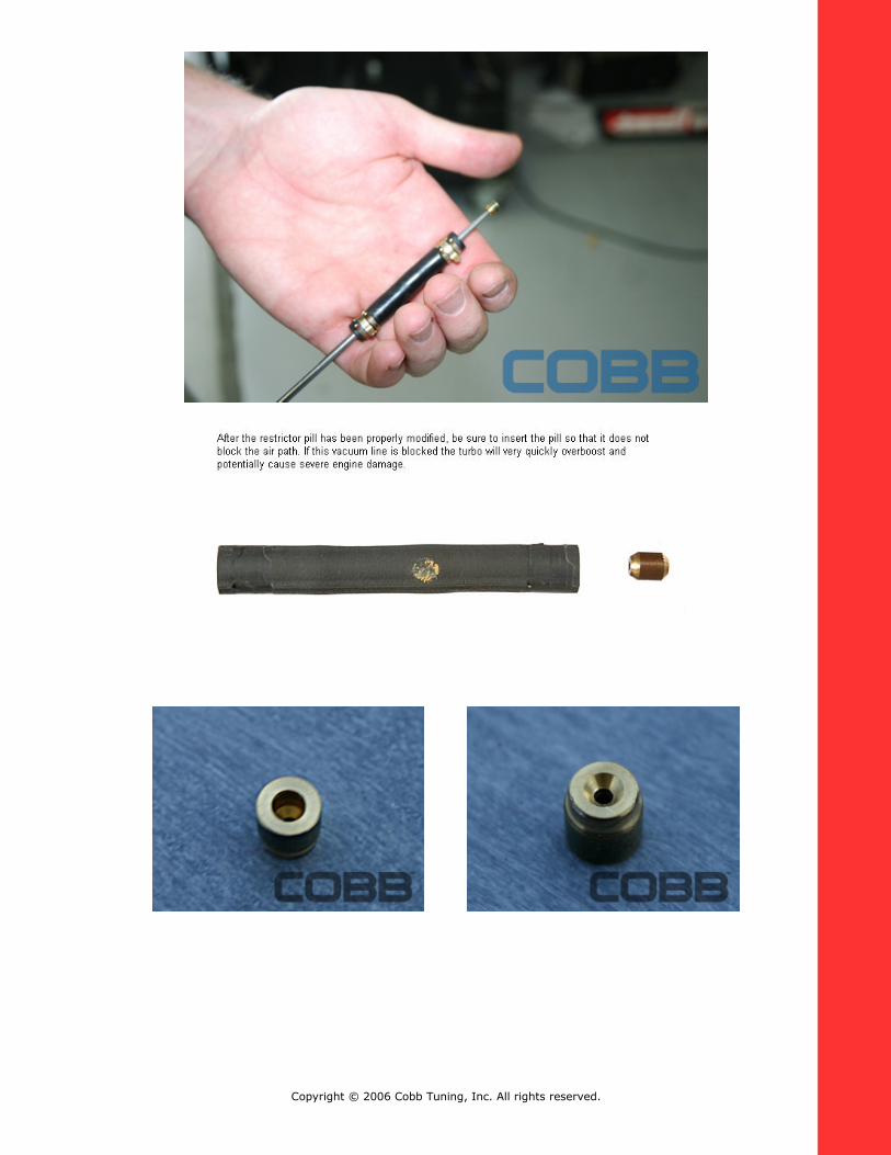
Primary Restrictor Pill - A small pill made of brass which contains a precision machined lengthwise hole in the center. This pill restricts the amount of air coming from the J-pipe (which is connected to the compressor housing).
Secondary Restrictor Pill - A small pill made of brass which contains a precision machined hole in the center. This pill restricts the amount of air that can be bled from the boost control system.
ECU - Also known as an ECM, PCM, EEC, EMS. The Engine Control Unit contains the processors, drivers, and logic which is calibrated to control the boost load via wastegate solenoid duty cycle.
Copyright © 2006 Cobb Tuning, Inc. All rights reserved.
Chapter 2 – Plumbing
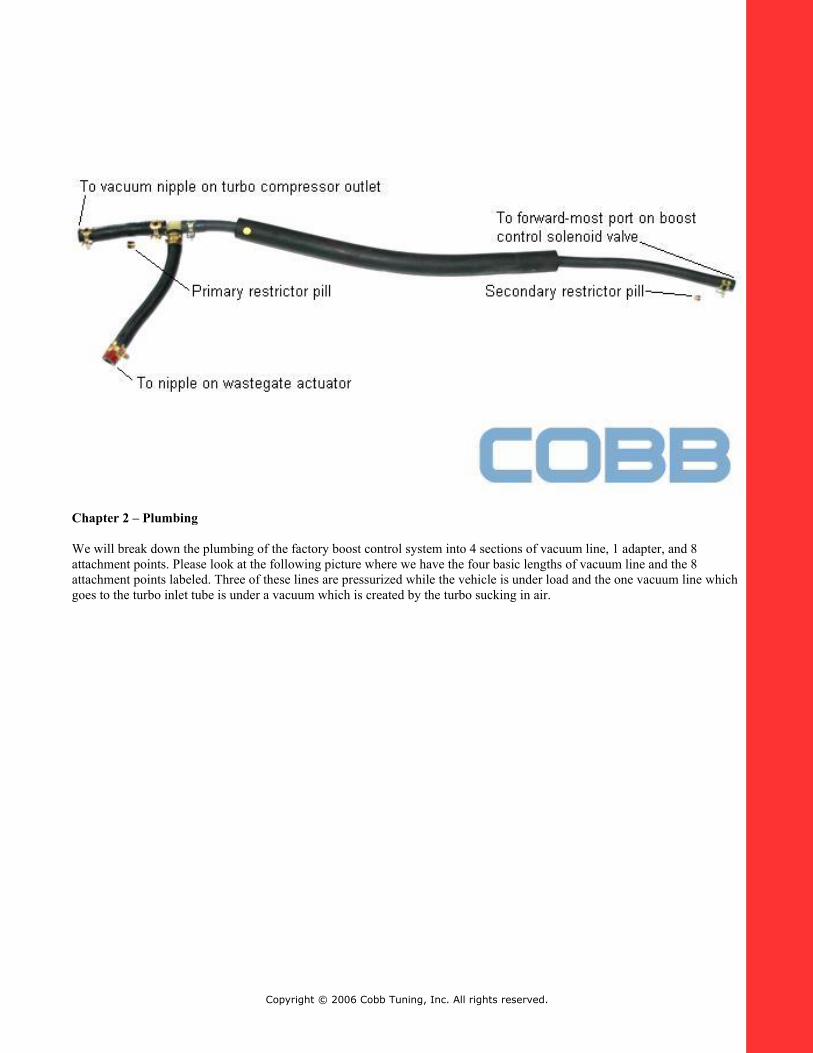
We will break down the plumbing of the factory boost control system into 4 sections of vacuum line, 1 adapter, and 8 attachment points. Please look at the following picture where we have the four basic lengths of vacuum line and the 8 attachment points labeled. Three of these lines are pressurized while the vehicle is under load and the one vacuum line which goes to the turbo inlet tube is under a vacuum which is created by the turbo sucking in air.
Copyright © 2006 Cobb Tuning, Inc. All rights reserved.
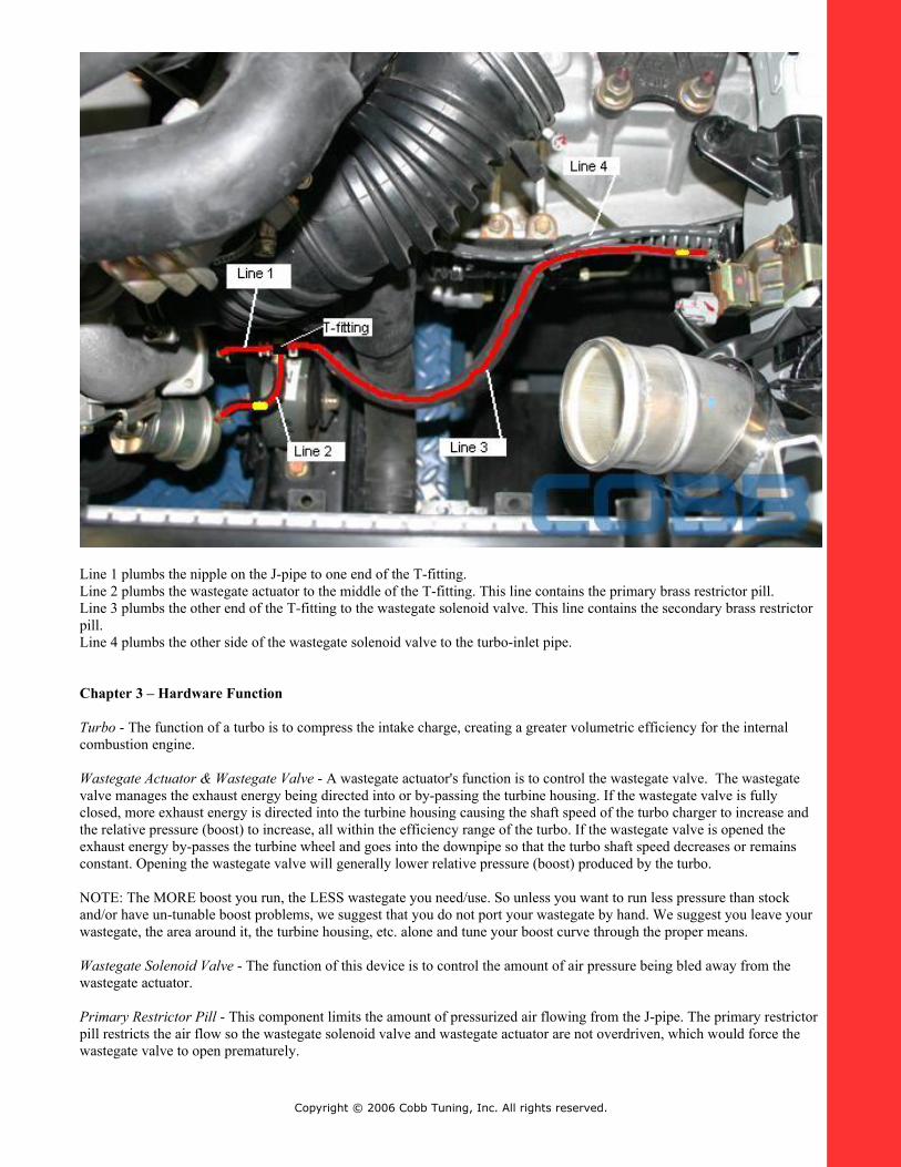
Line 1 plumbs the nipple on the J-pipe to one end of the T-fitting.Line 2 plumbs the wastegate actuator to the middle of the T-fitting. This line contains the primary brass restrictor pill.Line 3 plumbs the other end of the T-fitting to the wastegate solenoid valve. This line contains the secondary brass restrictor pill.Line 4 plumbs the other side of the wastegate solenoid valve to the turbo-inlet pipe.
Chapter 3 – Hardware Function
Turbo - The function of a turbo is to compress the intake charge, creating a greater volumetric efficiency for the internal combustion engine.
Wastegate Actuator & Wastegate Valve - A wastegate actuator's function is to control the wastegate valve. The wastegate valve manages the exhaust energy being directed into or by-passing the turbine housing. If the wastegate valve is fully closed, more exhaust energy is directed into the turbine housing causing the shaft speed of the turbo charger to increase and the relative pressure (boost) to increase, all within the efficiency range of the turbo. If the wastegate valve is opened the exhaust energy by-passes the turbine wheel and goes into the downpipe so that the turbo shaft speed decreases or remains constant. Opening the wastegate valve will generally lower relative pressure (boost) produced by the turbo. NOTE: The MORE boost you run, the LESS wastegate you need/use. So unless you want to run less pressure than stock and/or have un-tunable boost problems, we suggest that you do not port your wastegate by hand. We suggest you leave your wastegate, the area around it, the turbine housing, etc. alone and tune your boost curve through the proper means.
Wastegate Solenoid Valve - The function of this device is to control the amount of air pressure being bled away from the wastegate actuator.
Primary Restrictor Pill - This component limits the amount of pressurized air flowing from the J-pipe. The primary restrictor pill restricts the air flow so the wastegate solenoid valve and wastegate actuator are not overdriven, which would force the wastegate valve to open prematurely.
Copyright © 2006 Cobb Tuning, Inc. All rights reserved.
Secondary Restrictor Pill - This component limits the amount of pressurized air that the boost control solenoid can bleed to the intake system through the wastegate solenoid valve. The secondary restrictor pill restricts the air flow from the wastegate solenoid valve and wastegate actuator, which forces the wastegate valve to slightly open as the system runs. This will create a slight drop in boost pressure throughout the RPM range. Removing this restrictor pill will better allow the stock boost control system to hold boost to redline.
Vacuum Lines - Vacuum lines plumb pressurized air to the proper components so the Mitsubishi boost control system works properly.
ECU - This is the master device which controls the wastegate solenoid valve, the slave device, so that the targeted boost load is obtained.
The factory boost control system bleeds air pressure away from the wastegate actuator to the intake or turbo inlet pipe. With this device set at 0% wastegate duty cycle through the ECM calibration, all of the air pressure generated at the compressor housing will be applied to the wastegate actuator forcing the wastegate valve to fully open. When the wastegate actuator is fully open, the vehicle will run mechanical boost pressure which can be anything from 9-13psi on original equipment manufacturer (OEM) turbochargers. When this device is programmed to 100% wastegate duty cycle through the ECM calibration, all of the air pressure generated at the compressor housing will be allowed to by-pass to the wastegate actuator allowing the wastegate valve to close. The flow is limited by the size of the hole in the restrictor pill located in the first vacuum line attached to the nipple on the J-pipe off the compressor housing. The wastegate valve will only close as much as it can (taking into consideration that the exhaust gas pressure between the exhaust port and the turbocharger is generally greater than the manifold pressure the turbo is generating) with the exhaust gas pressure pushing on the wastegate valve.
NOTE: If you run a turbocharger beyond it’s compressor efficiency range, it will turn into a flame thrower.
Chapter 4 – Mechanical Calibration; Mechanical Tuning and Boost Control System Calibration Using the AccessECU StreetTUNER or ProTUNER Software
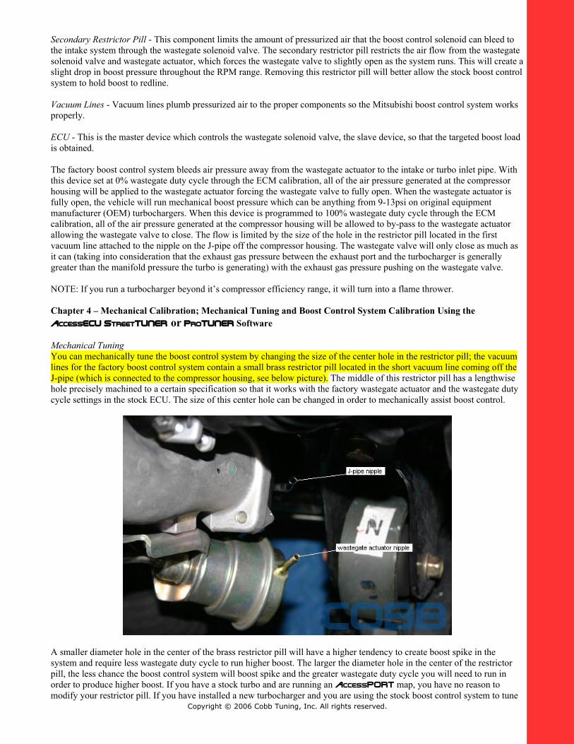
Mechanical TuningYou can mechanically tune the boost control system by changing the size of the center hole in the restrictor pill; the vacuum lines for the factory boost control system contain a small brass restrictor pill located in the short vacuum line coming off the J-pipe (which is connected to the compressor housing, see below picture). The middle of this restrictor pill has a lengthwise hole precisely machined to a certain specification so that it works with the factory wastegate actuator and the wastegate duty cycle settings in the stock ECU. The size of this center hole can be changed in order to mechanically assist boost control.
A smaller diameter hole in the center of the brass restrictor pill will have a higher tendency to create boost spike in the system and require less wastegate duty cycle to run higher boost. The larger the diameter hole in the center of the restrictor pill, the less chance the boost control system will boost spike and the greater wastegate duty cycle you will need to run in order to produce higher boost. If you have a stock turbo and are running an AccessPORT map, you have no reason to modify your restrictor pill. If you have installed a new turbocharger and you are using the stock boost control system to tune
Copyright © 2006 Cobb Tuning, Inc. All rights reserved.
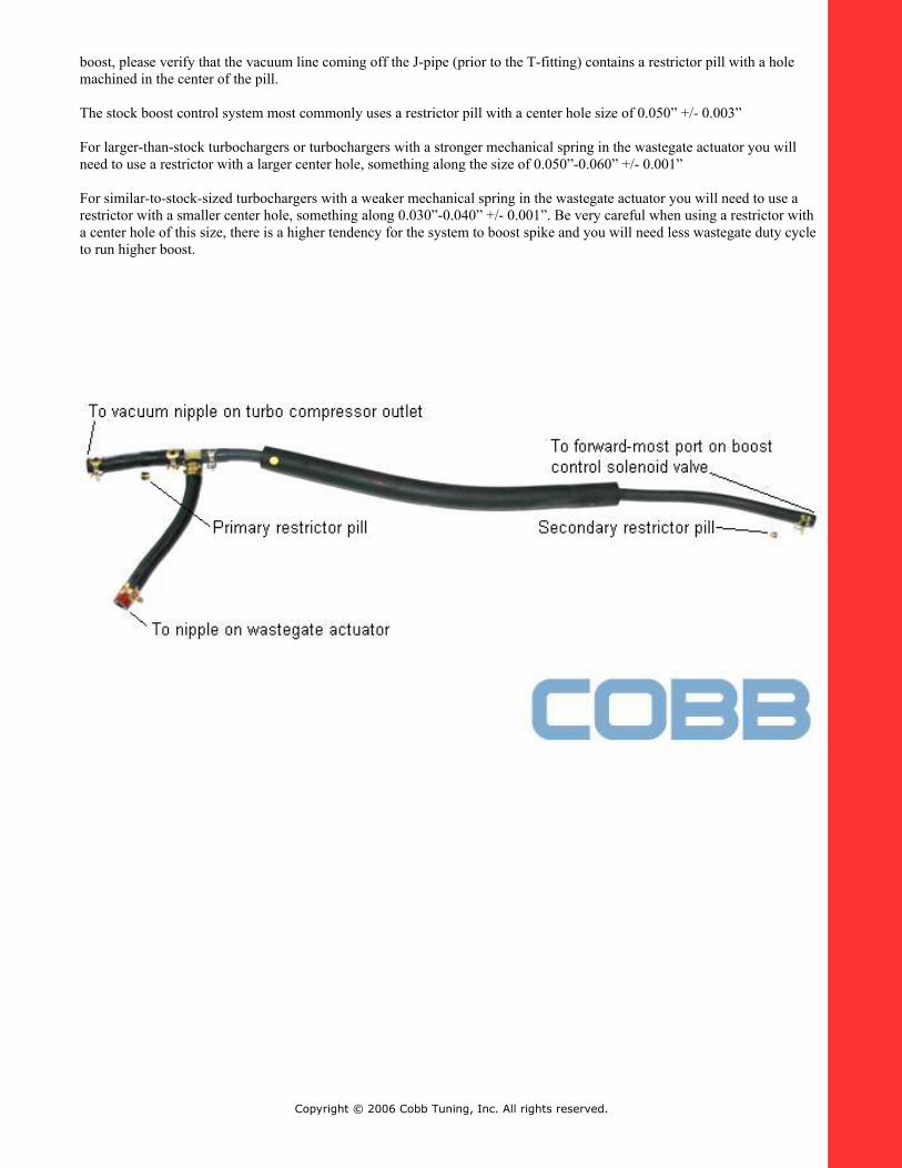
boost, please verify that the vacuum line coming off the J-pipe (prior to the T-fitting) contains a restrictor pill with a hole machined in the center of the pill.
The stock boost control system most commonly uses a restrictor pill with a center hole size of 0.050” +/- 0.003”
For larger-than-stock turbochargers or turbochargers with a stronger mechanical spring in the wastegate actuator you will need to use a restrictor with a larger center hole, something along the size of 0.050”-0.060” +/- 0.001”
For similar-to-stock-sized turbochargers with a weaker mechanical spring in the wastegate actuator you will need to use a restrictor with a smaller center hole, something along 0.030”-0.040” +/- 0.001”. Be very careful when using a restrictor with a center hole of this size, there is a higher tendency for the system to boost spike and you will need less wastegate duty cycle to run higher boost.
Copyright © 2006 Cobb Tuning, Inc. All rights reserved.
Copyright © 2006 Cobb Tuning, Inc. All rights reserved.
Copyright © 2006 Cobb Tuning, Inc. All rights reserved.
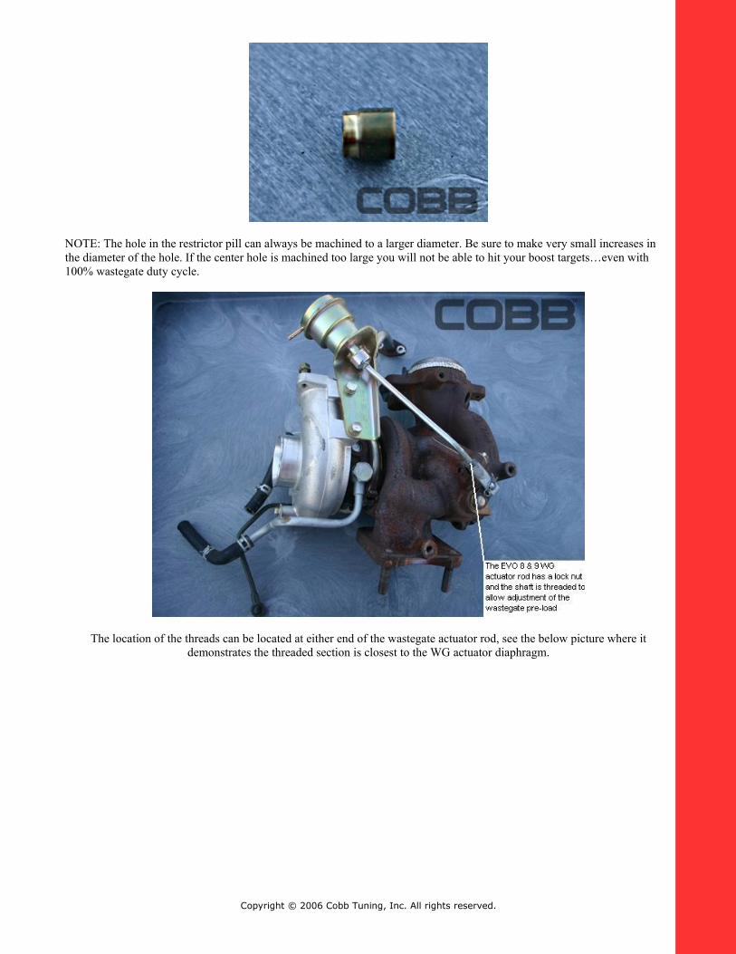
NOTE: The hole in the restrictor pill can always be machined to a larger diameter. Be sure to make very small increases in the diameter of the hole. If the center hole is machined too large you will not be able to hit your boost targets…even with 100% wastegate duty cycle.
The location of the threads can be located at either end of the wastegate actuator rod, see the below picture where it demonstrates the threaded section is closest to the WG actuator diaphragm.
Copyright © 2006 Cobb Tuning, Inc. All rights reserved.
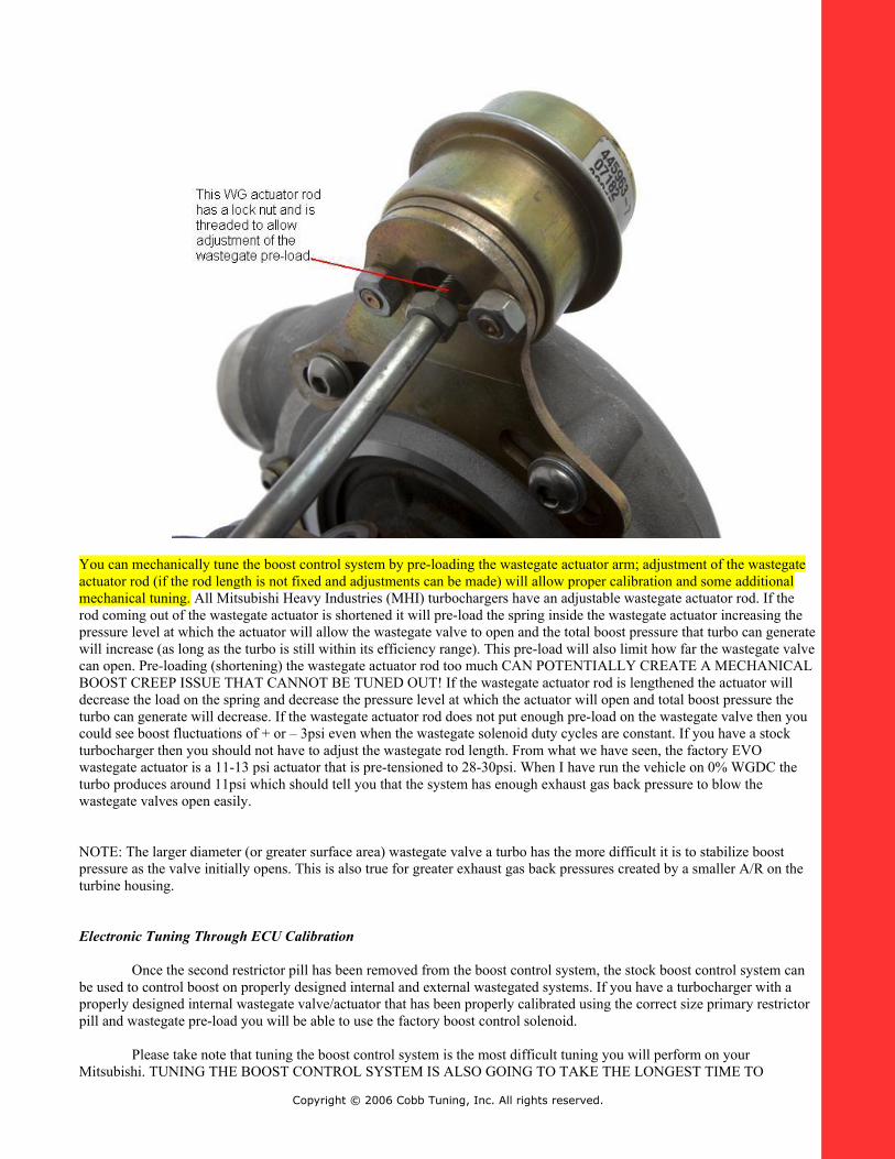
You can mechanically tune the boost control system by pre-loading the wastegate actuator arm; adjustment of the wastegate actuator rod (if the rod length is not fixed and adjustments can be made) will allow proper calibration and some additional mechanical tuning. All Mitsubishi Heavy Industries (MHI) turbochargers have an adjustable wastegate actuator rod. If the rod coming out of the wastegate actuator is shortened it will pre-load the spring inside the wastegate actuator increasing the pressure level at which the actuator will allow the wastegate valve to open and the total boost pressure that turbo can generate will increase (as long as the turbo is still within its efficiency range). This pre-load will also limit how far the wastegate valve can open. Pre-loading (shortening) the wastegate actuator rod too much CAN POTENTIALLY CREATE A MECHANICAL BOOST CREEP ISSUE THAT CANNOT BE TUNED OUT! If the wastegate actuator rod is lengthened the actuator will decrease the load on the spring and decrease the pressure level at which the actuator will open and total boost pressure the turbo can generate will decrease. If the wastegate actuator rod does not put enough pre-load on the wastegate valve then you could see boost fluctuations of + or – 3psi even when the wastegate solenoid duty cycles are constant. If you have a stock turbocharger then you should not have to adjust the wastegate rod length. From what we have seen, the factory EVO wastegate actuator is a 11-13 psi actuator that is pre-tensioned to 28-30psi. When I have run the vehicle on 0% WGDC the turbo produces around 11psi which should tell you that the system has enough exhaust gas back pressure to blow the wastegate valves open easily.
NOTE: The larger diameter (or greater surface area) wastegate valve a turbo has the more difficult it is to stabilize boost pressure as the valve initially opens. This is also true for greater exhaust gas back pressures created by a smaller A/R on the turbine housing.
Electronic Tuning Through ECU Calibration
Once the second restrictor pill has been removed from the boost control system, the stock boost control system can be used to control boost on properly designed internal and external wastegated systems. If you have a turbocharger with a properly designed internal wastegate valve/actuator that has been properly calibrated using the correct size primary restrictor pill and wastegate pre-load you will be able to use the factory boost control solenoid.
Please take note that tuning the boost control system is the most difficult tuning you will perform on your Mitsubishi. TUNING THE BOOST CONTROL SYSTEM IS ALSO GOING TO TAKE THE LONGEST TIME TO
Copyright © 2006 Cobb Tuning, Inc. All rights reserved.
COMPLETE. Although, once you are finished tuning your boost control system you will be very appreciative of the complexity and capability of the OEM boost control system. The OEM boost control system is much faster than any human input so we highly suggest you start with lower wastegate duty cycles than you may need and work your way up from there. The boost curve and the stability of the boost curve must be established in order to allow you to properly tune all tables from this point on. The MAF signal has a major influence on the ignition advance and fuel curve since this signal is the major component used by the ECU to calculate engine load.
Mitsubishi boost control systems employ a closed-loop, targeting system for tuning boost. You must first establish your boost load targets in the Boost Targets table. Achieving these boost load targets is going to be the primary goal for the ECU. The ECU will start by using the wastegate duty cycles established in the Wastegate Duty Cycles table(s). Some Mitsubishi ECUs use a single Wastegate Duty Cycles table and some use more. We have composed a worksheet called the “AccessECU Calibration & Tuning Guide Worksheet for Mitsubishis” which has various tabs set up to assist you with the WGDC calibrations. The ECU will then use the Turbo Dynamics tables adjust the wastegate duty cycle in order to achieve the dictated boost targets. Other compensatory boost and wastegate tables are also used by the ECU to fine tune boost for environmental changes, temperature, barometric pressure, etc. If the wastegate duty cycle values are too low, you will not achieve your target boost load. If the wastegate duty cycle values are too high, you will overshoot your boost targets and potentially damage the engine. We do not suggest you run a wastegate duty cycle of more than 98% to prevent overheating or lock-up of the wastegate solenoid, and to promote the longevity of the wastegate solenoid.
While tuning the boost control system you will want to datalog and/or view your Boost Load, RPM, Throttle Position, Turbo Dynamics, and Wastegate Duty Cycle values so you can see what your ECU is actually doing to achieve its boost load targets. The further your turbo dynamics value is from zero, the further off your wastegate duty cycles are from ideal. We suggest you tune so that your turbo dynamics is a small (10 or less) number across the RPM range.
If your datalogged turbo dynamics value is a negative value then your ECU will remove wastegate duty cycles to hit your boost targets because the engine is over-boosting; the calculated boost load is higher than what is dictated in the Boost Targets table for the given RPM value. If your boost is surging up and down then your boost control is searching because the engine is grossly overshooting it’s target. If your datalog shows a negative value for turbo dynamics then the ECU will use the additional authority in the negative portion of the Turbo Dynamics tables to lower WGDC until the target boost load is achieved.
If your datalogged turbo dynamics value is a positive value then your ECU will add wastegate duty cycles to hit your boost load targets because the engine is under-boosting. If your turbo dynamics is a negative value then your ECU will remove wastegate duty cycles to hit your boost load targets because the engine is over-boosting; the calculated boost load is higher than what is dictated in the Boost Targets table for the given RPM values. If your boost is surging up and down then your boost control is searching because it is grossly overshooting its target. If your datalog shows a positive value for turbo dynamics then the ECU will use the additional authority in the positive portion of the Turbo Dynamics tables to increase WGDC until the target boost is achieved.
If you are increasing or holding wastegate duty cycles steady and boost is dropping then you have most likely reached the threshold of the mechanical efficiency of the turbo or your exhaust gas back pressure prior to the turbo is too high and is forcing the wastegate valve to open.
If you are having a small boost spike you may need to decrease the WGDC percentage a few hundred RPM prior to the overboosting event to allow the exhaust energy to be released past the turbine wheel.
NOTE: With porting a wastegate, you are trying to make the wastegate valve function potentially work better which means that your turbo is going to lower boost super fast when the wastegate door/valve opens or not run as much boost as it was engineered to. If you make your wastegate react quicker then boost will be very difficult to stabilize and reach peak #s at an earlier RPM. If you make the wastegate flow better, then the exhaust energy your turbo needs to make and maintain boost will have less opportunity to flow across the turbine wheel. Generally speaking, air/pressure/exhaust gases will always flow along the path of least resistance. Not bashing, just trying to give you a different perspective.
Copyright © 2006 Cobb Tuning, Inc. All rights reserved.
COBB Tuning, Inc.3362 West 1820 South
Salt Lake City, UT 84104Phone (801) 713-0035Fax (801) 478-0925
www.cobbtuning.comwww.cobbforums.com
v1.05
Copyright © 2006 Cobb Tuning, Inc. All rights reserved.