Embed Size (px)
Citation preview

HORNET Remote Control SystemsHORNET Remote Control SystemsHORNET Remote Control SystemsHORNET Remote Control Systems
DS HORNET-9 ©2009 REG No 277 4001, Lewes, England. Page 1
DescriptionDescriptionDescriptionDescription
Supplied complete ready to go the HORNET is a rugged IP68 weatherproof remote
control system. Built in mounting points and easy wiring using High Quality screw
Terminals.
With a range of up to100m the HORNET is ideal for a wide variety of switching appli-
cations.
Additional transmitters may be added using the ‘learn’ process, any button on the
transmitter can be used to control one or many outputs of the receiver.
• Up to 100metres Range
• 1 – 3 Button versions
• 12-30Vdc 0r 230Vac versions
• Reliable FM Technology
• Up to four 1000W Relay switches
• Waterproof Receiver (IP68)
• Momentary or Latching Relays
• Any Switch Map to Any Relay
Output
• General Purpose Remote General Purpose Remote General Purpose Remote General Purpose Remote
SwitchingSwitchingSwitchingSwitching
• Electric GatesElectric GatesElectric GatesElectric Gates
• Roller Shutter DoorsRoller Shutter DoorsRoller Shutter DoorsRoller Shutter Doors
• Garden LightingGarden LightingGarden LightingGarden Lighting
HORNET Remote Control SystemsHORNET Remote Control SystemsHORNET Remote Control SystemsHORNET Remote Control Systems
DS HORNET-9 ©2009 REG No 277 4001, Lewes, England. Page 2
HORNETHORNETHORNETHORNET----S1 / HORNETS1 / HORNETS1 / HORNETS1 / HORNET----S2 / HORNETS2 / HORNETS2 / HORNETS2 / HORNET----S3 (12S3 (12S3 (12S3 (12----32Vdc Receivers)32Vdc Receivers)32Vdc Receivers)32Vdc Receivers)
The HORNET system provides up to 4 isolated switches each capable of switching
up to 6A @230V
1. Open the enclosure by removing the two fixing screws from the base of the
enclosure and remove the antenna, the board should then slide out.
2. Wire the power as shown on Fig 1.1
3. Wire your chosen switch as required
4. Once the receiver is set-up; transmitter button 1 will switch relay 1 (button
two to relay two and so on). Each button press will change the state of the
relay (i.e. one press for on, one press for off).
HORNET Remote Control SystemsHORNET Remote Control SystemsHORNET Remote Control SystemsHORNET Remote Control Systems
DS HORNET-9 ©2009 REG No 277 4001, Lewes, England. Page 3
Advanced OperationAdvanced OperationAdvanced OperationAdvanced Operation
To pair a new transmitter switch follow this procedureTo pair a new transmitter switch follow this procedureTo pair a new transmitter switch follow this procedureTo pair a new transmitter switch follow this procedure
Any transmitter button can be configured to operate any of the receiver relays.
Pair any Transmitter switch with a receiver relay by following this procedure:
1. Select the receiver output relay to learn to:
2. Briefly press the receiver Pairing switch (S2) once
3. The Learn LED will flash once to indicate relay 1 is selected
4. After the LED stops flashing, press the Learn switch again to select the next
relay channel
5. Repeat step 4 until the required relay is selected.
6. Press the button on the transmitter you want to learn to the relay.
7. The Learn LED will flash to indicate Pairing is complete.
Pairing a Transmitter to a ReceiverPairing a Transmitter to a ReceiverPairing a Transmitter to a ReceiverPairing a Transmitter to a Receiver
The only limitation is that each receiver has a maximum memory for up to 40 pairings,
these can be from the same or any number of transmitters.
Erasing Receivers Memory Erasing Receivers Memory Erasing Receivers Memory Erasing Receivers Memory
1. Press and hold the receiver Learn Switch for approx 10 seconds.
2. When the Learn LED turns ON all memory is erased
NOTE:NOTE:NOTE:NOTE: You cannot erase individual Tx encoders
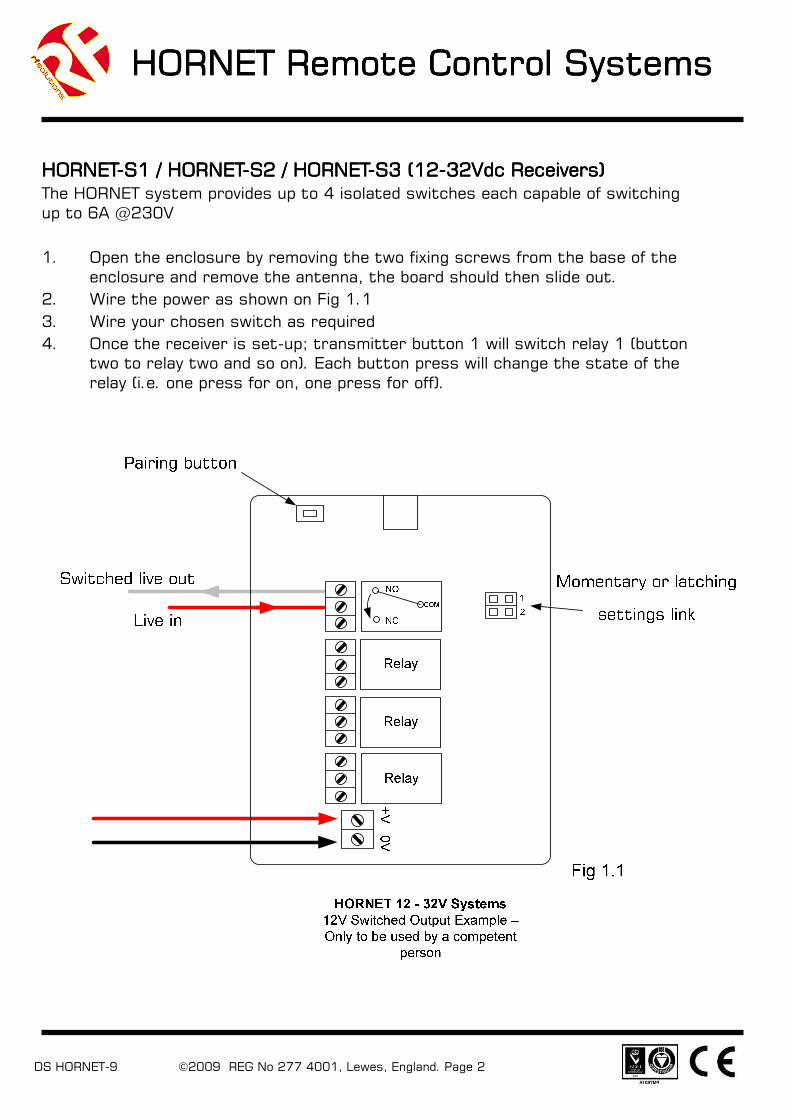
Configuring Relays Configuring Relays Configuring Relays Configuring Relays
The jumper links set the outputs to be Momentary (operates as long as transmitter is
operated)
or Latching (Relay changes state each time transmitter is pressed).
The jumper links are made / removed by the small link ‘cap’ placed over the pin header.
See Fig 1.1 for location of jumper pins.
Link PositionsLink PositionsLink PositionsLink Positions RelaysRelaysRelaysRelays
LK1LK1LK1LK1 LK2LK2LK2LK2 RLY 1RLY 1RLY 1RLY 1 RLY 2RLY 2RLY 2RLY 2 RLY 3RLY 3RLY 3RLY 3 RLY 4RLY 4RLY 4RLY 4
Closed Closed Mom Mom Mom Mom
Closed Open Mom Mom Latch Latch
Open Closed Mom Latch Latch Latch
Open Open Latch Latch Latch Latch
HORNET Remote Control SystemsHORNET Remote Control SystemsHORNET Remote Control SystemsHORNET Remote Control Systems
DS HORNET-9 ©2009 REG No 277 4001, Lewes, England. Page 4
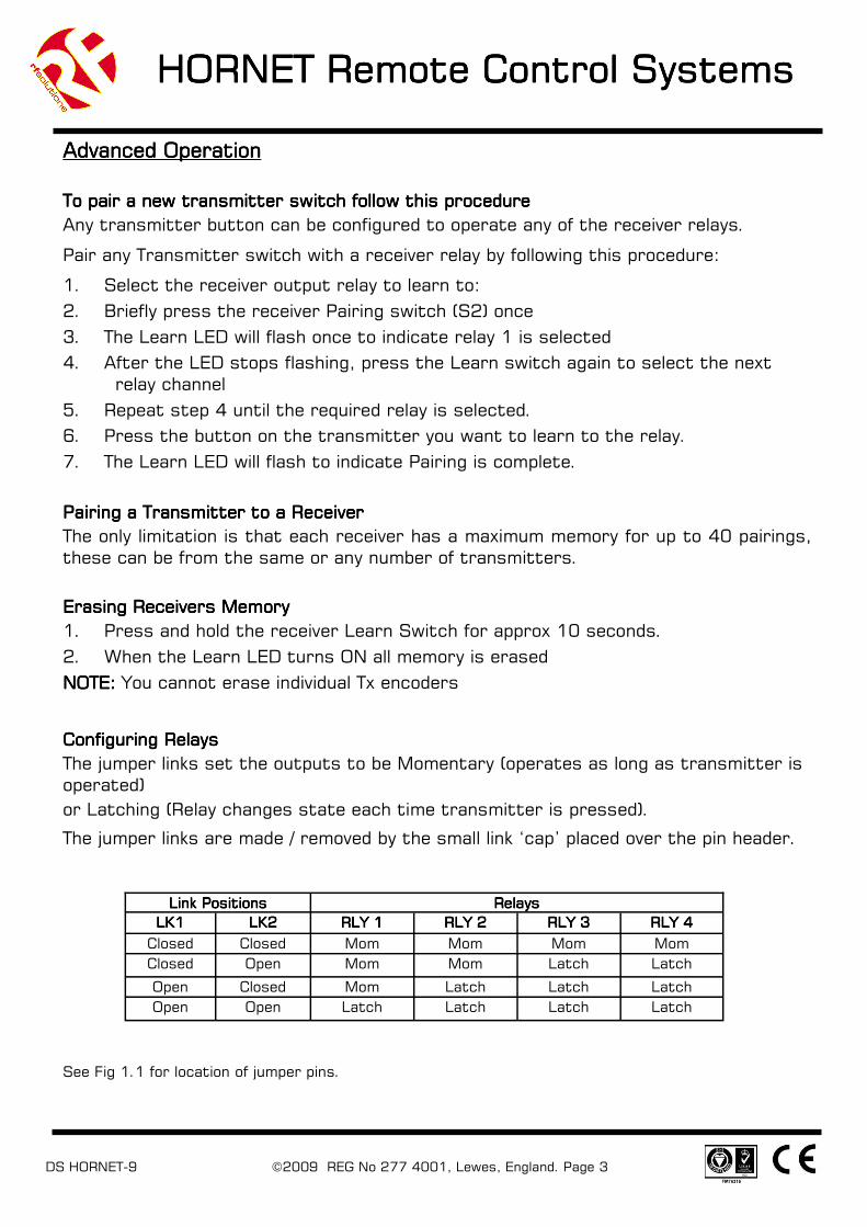
HORNETHORNETHORNETHORNET----S1M / HORNET S2M (230Vac Powered Receivers)S1M / HORNET S2M (230Vac Powered Receivers)S1M / HORNET S2M (230Vac Powered Receivers)S1M / HORNET S2M (230Vac Powered Receivers)
The HORNET system provides up to 4 isolated switches each capable of switching up
to 6A @230V
1. Open the enclosure by removing the two fixing screws from the base of the
enclosure and the antenna, the board should then slide out.
2. Wire the power as shown on Fig 1.2
3. Wire your chosen switch as required
4. Once the receiver is set-up transmitter button 1 will switch relay 1 (button two
relay two and so on). Each button will change the state of the relay (i.e. one
press for on, one press for off).
HORNET Remote Control SystemsHORNET Remote Control SystemsHORNET Remote Control SystemsHORNET Remote Control Systems
DS HORNET-9 ©2009 REG No 277 4001, Lewes, England. Page 5
Advanced OperationAdvanced OperationAdvanced OperationAdvanced Operation
Please Note:Please Note:Please Note:Please Note: During Learn and Erase the relays operate at high speed. They should be isolated from sensi-tive equipment during this process.
To Pair additional Transmitter buttons to receiver Relay #1To Pair additional Transmitter buttons to receiver Relay #1To Pair additional Transmitter buttons to receiver Relay #1To Pair additional Transmitter buttons to receiver Relay #1
1. Apply power the receiver and wait 10secs for the unit to enter ‘normal operation’ mode.
2. Switch the receiver unit OFF and then ON again in ~1sec intervals FOURFOURFOURFOUR times finally leaving the unit
powered.
3. The receiver emits a continuous ‘Click’ to confirm it is now in ‘learn’ Mode
4. Press the chosen transmitter button.
5. The receiver will acknowledge by sounding the a single ’buzz’
6. Learn Process complete.
To Pair additional Transmitter buttons to receiver Relay #2To Pair additional Transmitter buttons to receiver Relay #2To Pair additional Transmitter buttons to receiver Relay #2To Pair additional Transmitter buttons to receiver Relay #2
1. Apply power the receiver and wait 10secs for the unit to enter ‘normal operation’ mode.
2. Switch the receiver unit OFF and then ON again in ~1sec intervals SIXSIXSIXSIX times finally leaving the unit
powered.
3. The receiver emits a continuous ‘Click’ to confirm it is now in ‘learn’ Mode
4. Press the chosen transmitter button.
5. The receiver will acknowledge by sounding the two ’buzzes’
6. Learn Process complete.
Erasing Receivers Memory Erasing Receivers Memory Erasing Receivers Memory Erasing Receivers Memory
1. Power the receiver unit up and wait 10 seconds for the unit to enter ‘normal operation’ mode.
2. Switch the unit off and then on again at ~1 second intervals TENTENTENTEN times, leaving the unit powered.
3. The receiver confirms Erase cycle complete by giving three short ‘Buzzes’
4. The unit has now erased all encoder data.
NOTE:NOTE:NOTE:NOTE: You cannot erase individual Tx encoders
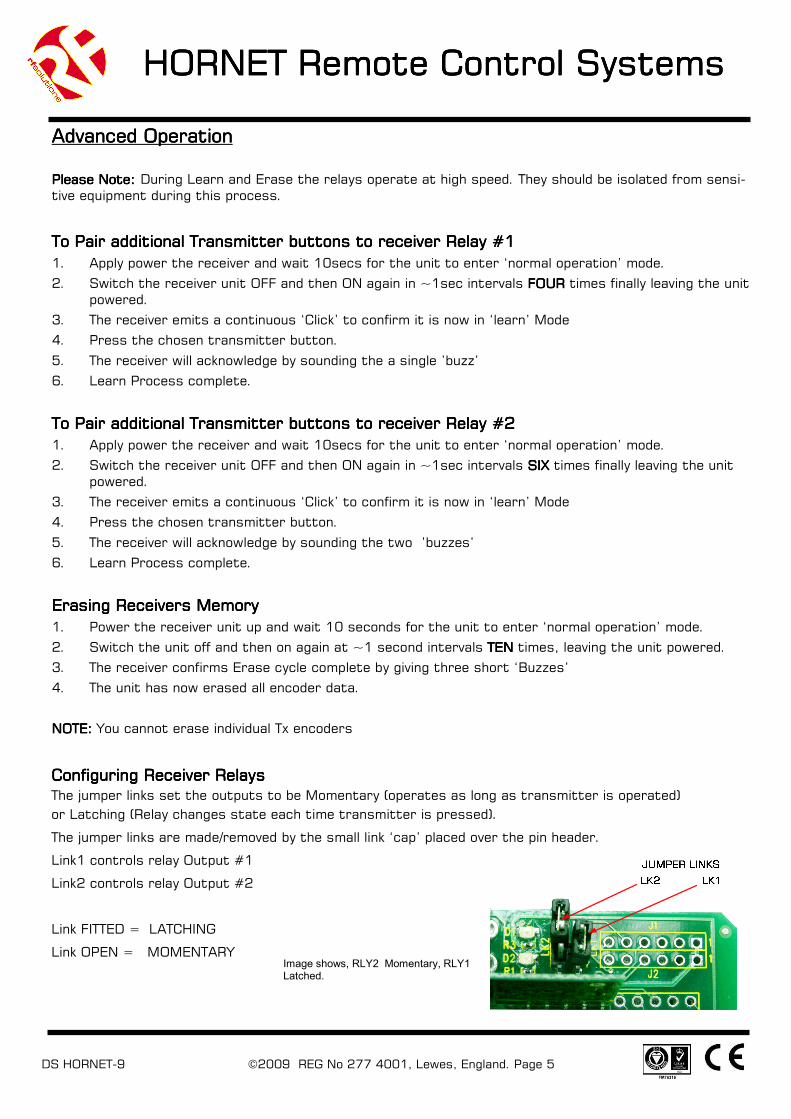
Configuring Receiver RelaysConfiguring Receiver RelaysConfiguring Receiver RelaysConfiguring Receiver Relays
The jumper links set the outputs to be Momentary (operates as long as transmitter is operated)
or Latching (Relay changes state each time transmitter is pressed).
The jumper links are made/removed by the small link ‘cap’ placed over the pin header.
Link1 controls relay Output #1
Link2 controls relay Output #2
Link FITTED = LATCHING
Link OPEN = MOMENTARY Image shows, RLY2 Momentary, RLY1 Latched.

HORNET Remote Control SystemsHORNET Remote Control SystemsHORNET Remote Control SystemsHORNET Remote Control Systems
DS HORNET-9 ©2009 REG No 277 4001, Lewes, England. Page 6
System Part Numbers System Part Numbers System Part Numbers System Part Numbers
Operating from 12 Operating from 12 Operating from 12 Operating from 12----30Vdc30Vdc30Vdc30Vdc
Systems Operating at 230VacSystems Operating at 230VacSystems Operating at 230VacSystems Operating at 230Vac
**Range stated is optimum, direct line of sight. In worst conditions this can be reduced by over 50%
Part NumberPart NumberPart NumberPart Number DescriptionDescriptionDescriptionDescription
HORNET-TX1 Transmitter 1 switch
HORNET-TX2 Transmitter 2 switch
HORNET-TX3 Transmitter 3 switch
HORNET -TX-IPKIT ’O’ Ring, Seals Transmitter to IP65
Additional TransmittersAdditional TransmittersAdditional TransmittersAdditional Transmitters
Part NumberPart NumberPart NumberPart Number DescriptionDescriptionDescriptionDescription FrequencyFrequencyFrequencyFrequency
(MHz)(MHz)(MHz)(MHz)
Range**Range**Range**Range**
(Metres)(Metres)(Metres)(Metres)
HORNET-S1 System 1 channel 433.92 100
HORNET-S2 System 2 channel 433.92 100
HORNET-S3 System 3 channel 433.92 100
Part NumberPart NumberPart NumberPart Number DescriptionDescriptionDescriptionDescription FrequencyFrequencyFrequencyFrequency
(MHz)(MHz)(MHz)(MHz)
Range**Range**Range**Range**
(Metres)(Metres)(Metres)(Metres)
HORNET-S1M System 1 channel 433.92 100
HORNET-S2M System 2 channel 433.92 100
Bespoke VersionsBespoke VersionsBespoke VersionsBespoke Versions
Custom versions available with your own logo
and or protocol.
Please contact Sales for further info.
HORNET Remote Control SystemsHORNET Remote Control SystemsHORNET Remote Control SystemsHORNET Remote Control Systems
DS HORNET-9 ©2009 REG No 277 4001, Lewes, England. Page 7
Low Battery IndicationLow Battery IndicationLow Battery IndicationLow Battery Indication
When the battery on the HORNET-TX becomes low (<2.1V) the LED will indicate this by pulsing on and
off and one second intervals. The battery should be changed at this point. When the battery reaches
this level the HORNET-TX may continue to operate but the range will be reduced and the LED will dim.
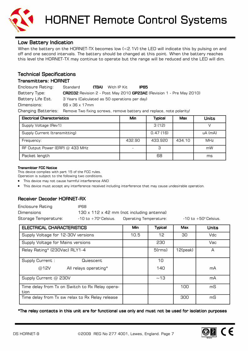
Technical SpecificationsTechnical SpecificationsTechnical SpecificationsTechnical Specifications
Transmitters: HORNETTransmitters: HORNETTransmitters: HORNETTransmitters: HORNET
Enclosure Rating: Standard (TBA) (TBA) (TBA) (TBA) With IP Kit IP65 IP65 IP65 IP65
Battery Type: CR2032CR2032CR2032CR2032 Revision 2 - Post May 2010 GP23AE GP23AE GP23AE GP23AE (Revision 1 - Pre May 2010)
Battery Life Est. 3 Years (Calculated as 50 operations per day)
Dimensions: 66 x 36 x 17mm
Changing Batteries: Remove Two fixing screws, remove battery and replace, note polarity!
Transmitter FCC NoticeTransmitter FCC NoticeTransmitter FCC NoticeTransmitter FCC Notice
This device complies with part 15 of the FCC rules.
Operation is subject to the following two conditions.
• This device may not cause harmful interference AND
• This device must accept any interference received including interference that may cause undesirable operation.
Receiver Decoder HORNETReceiver Decoder HORNETReceiver Decoder HORNETReceiver Decoder HORNET----RXRXRXRX
Enclosure Rating IP68
Dimensions 130 x 112 x 42 mm (not including antenna)
Storage Temperature: -10 to +70o Celsius. Operating Temperature: -10 to +50o Celsius.
*The relay contacts in this unit are for functional use only and must not be used for isolation purposes*The relay contacts in this unit are for functional use only and must not be used for isolation purposes*The relay contacts in this unit are for functional use only and must not be used for isolation purposes*The relay contacts in this unit are for functional use only and must not be used for isolation purposes
Electrical CharacteristicsElectrical CharacteristicsElectrical CharacteristicsElectrical Characteristics MinMinMinMin TypicalTypicalTypicalTypical MaxMaxMaxMax UnitsUnitsUnitsUnits
Supply Voltage (Rev1) 3 (12) V
Supply Current (transmitting) 0.47 (16) uA (mA)
Frequency: 432.90 433.920 434.10 MHz
RF Output Power (ERP) @ 433 MHz - 3 mW
Packet length 68 ms
ELECTRICAL CHARACTERISTICSELECTRICAL CHARACTERISTICSELECTRICAL CHARACTERISTICSELECTRICAL CHARACTERISTICS MinMinMinMin TypicalTypicalTypicalTypical MaxMaxMaxMax UnitsUnitsUnitsUnits
Supply Voltage for 12-30V versions 10.5 12 30 Vdc
Supply Voltage for Mains versions 230 Vac
Supply Current : Quiescent
@12V All relays operating*
10
140
mA
Time delay from Tx on Switch to Rx Relay opera-
tion
100 mS
Time delay from Tx sw relax to Rx Relay release 300 mS
Relay Rating* (230Vac) RLY1-4 5(rms) 12(peak) A
Supply Current @ 230V ~~13 mA
HORNET Remote Control SystemsHORNET Remote Control SystemsHORNET Remote Control SystemsHORNET Remote Control Systems
DS HORNET-9 ©2009 REG No 277 4001, Lewes, England. Page 8
R F Solutions Ltd.,R F Solutions Ltd.,R F Solutions Ltd.,R F Solutions Ltd.,
Unit 21, Cliffe Industrial Estate,Unit 21, Cliffe Industrial Estate,Unit 21, Cliffe Industrial Estate,Unit 21, Cliffe Industrial Estate,
Lewes, E. Sussex. BN8 6JL. England.Lewes, E. Sussex. BN8 6JL. England.Lewes, E. Sussex. BN8 6JL. England.Lewes, E. Sussex. BN8 6JL. England.
Email : Email : Email : Email : [email protected]@[email protected]@rfsolutions.co.uk http://www.rfsolutions.co.ukhttp://www.rfsolutions.co.ukhttp://www.rfsolutions.co.ukhttp://www.rfsolutions.co.uk
Tel: +44 (0)1273 898 000Tel: +44 (0)1273 898 000Tel: +44 (0)1273 898 000Tel: +44 (0)1273 898 000 Fax: +44 (0)1273 480 661Fax: +44 (0)1273 480 661Fax: +44 (0)1273 480 661Fax: +44 (0)1273 480 661
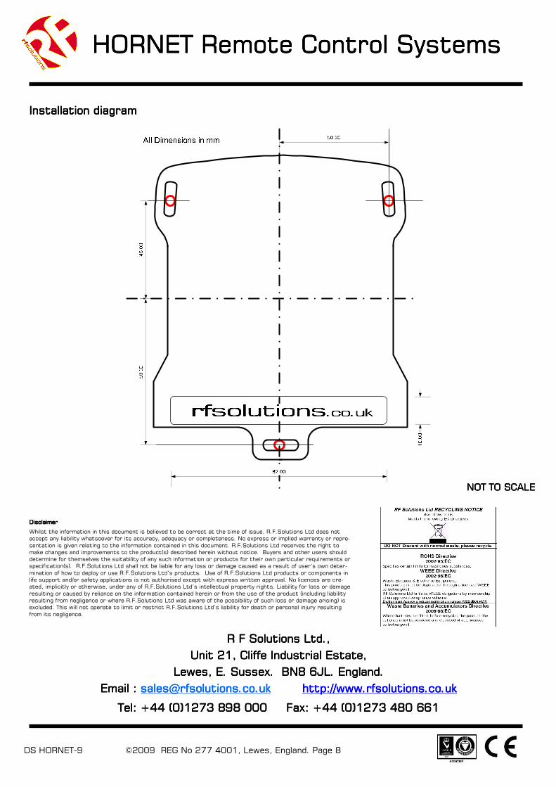
Installation diagram Installation diagram Installation diagram Installation diagram
NOT TO SCALENOT TO SCALENOT TO SCALENOT TO SCALE
DisclaimerDisclaimerDisclaimerDisclaimer
Whilst the information in this document is believed to be correct at the time of issue, R.F.Solutions Ltd does not
accept any liability whatsoever for its accuracy, adequacy or completeness. No express or implied warranty or repre-
sentation is given relating to the information contained in this document. R.F.Solutions Ltd reserves the right to
make changes and improvements to the product(s) described herein without notice. Buyers and other users should
determine for themselves the suitability of any such information or products for their own particular requirements or
specification(s). R.F.Solutions Ltd shall not be liable for any loss or damage caused as a result of user’s own deter-
mination of how to deploy or use R.F.Solutions Ltd’s products. Use of R.F.Solutions Ltd products or components in
life support and/or safety applications is not authorised except with express written approval. No licences are cre-
ated, implicitly or otherwise, under any of R.F.Solutions Ltd’s intellectual property rights. Liability for loss or damage
resulting or caused by reliance on the information contained herein or from the use of the product (including liability
resulting from negligence or where R.F.Solutions Ltd was aware of the possibility of such loss or damage arising) is
excluded. This will not operate to limit or restrict R.F.Solutions Ltd’s liability for death or personal injury resulting
from its negligence.