Embed Size (px)
Citation preview
®
HORIZONTAL DIRECTIONAL DRILLINGWITH DUCTILE IRON PIPE
Introduction
Horizontal Directional Drilling (HDD) is a trenchless methodology that provides an installation alternative that can offer a number of ben-efits over traditional open-cut. HDD can be implemented with very little disruption to surface activities, requires less working space, andmay be performed more quickly than open-cut methods. Also, it can simplify or eliminate certain permitting processes. This type ofinstallation of municipal underground infrastructure systems has seen a dramatic increase in recent years. Although there are currentlyno national standards regarding HDD installations for any pipe material, HDD pipeline installations are becoming more and more commonand may be the fastest growing trenchless construction method today. They can be used to install new pipelines or replace existing ones.
Procedure
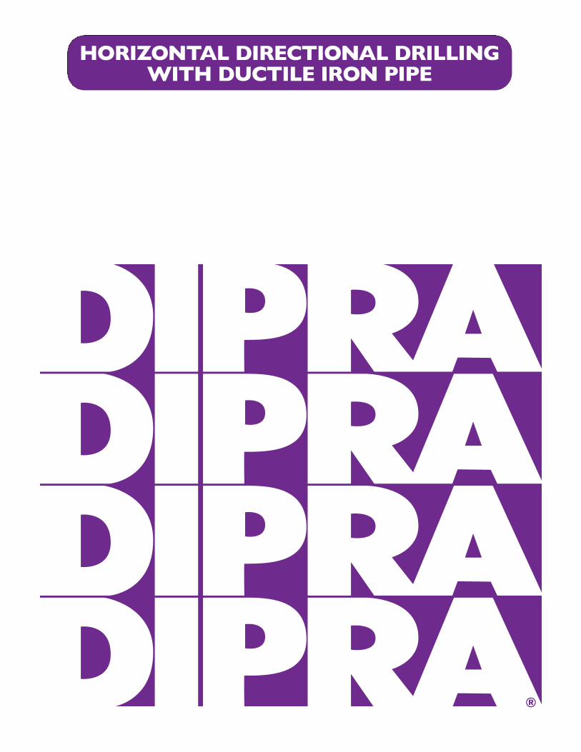
HDD is a trenchless construction method that involves drilling a small pilot hole, using technology that allows the drill to besteered and tracked from the surface. The pilot bore is launched from the surface at an angle between 8 and 20 degrees to thehorizontal, and transitions to horizontal as the required depth is reached. A bore path of very gradual curvature or near-straightalignment is normally followed to minimize friction and to stay within the allowable joint deflection and the allowable curveradius for the pipe. This minimizes the chance of getting the pipeline “hung up” in the soil or damaging the pipe.
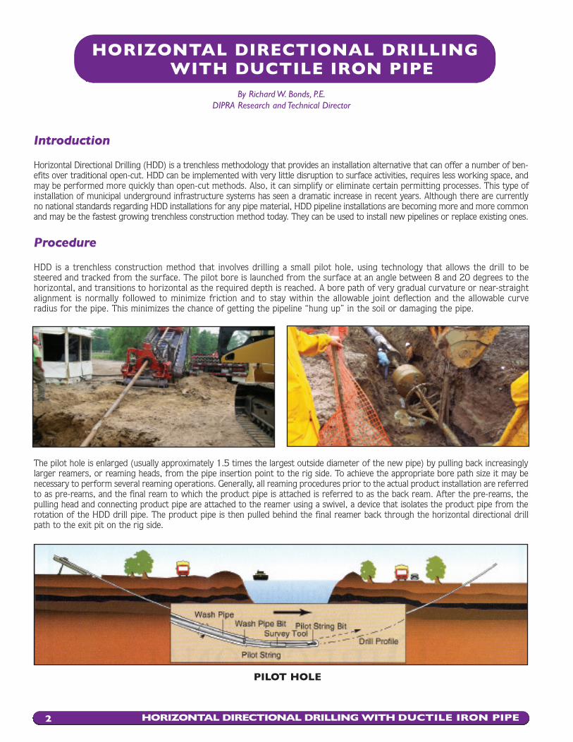
The pilot hole is enlarged (usually approximately 1.5 times the largest outside diameter of the new pipe) by pulling back increasinglylarger reamers, or reaming heads, from the pipe insertion point to the rig side. To achieve the appropriate bore path size it may benecessary to perform several reaming operations. Generally, all reaming procedures prior to the actual product installation are referredto as pre-reams, and the final ream to which the product pipe is attached is referred to as the back ream. After the pre-reams, thepulling head and connecting product pipe are attached to the reamer using a swivel, a device that isolates the product pipe from therotation of the HDD drill pipe. The product pipe is then pulled behind the final reamer back through the horizontal directional drillpath to the exit pit on the rig side.
HORIZONTAL DIRECTIONAL DRILLINGWITH DUCTILE IRON PIPE
By Richard W. Bonds, P.E.DIPRA Research and Technical Director
HORIZONTAL DIRECTIONAL DRILLING WITH DUCTILE IRON PIPE2
PILOT HOLE
Drilling Mud
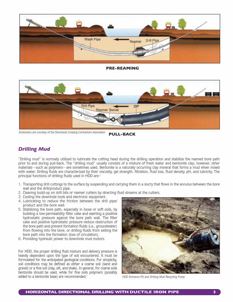
“Drilling mud” is normally utilized to lubricate the cutting head during the drilling operation and stabilize the reamed bore pathprior to and during pull-back. The “drilling mud” usually consists of a mixture of fresh water and bentonite clay; however, othermaterials—such as polymers—are sometimes used. Bentonite is a naturally occurring clay mineral that forms a mud when mixedwith water. Drilling fluids are characterized by their viscosity, gel strength, filtration, fluid loss, fluid density, pH, and lubricity. Theprincipal functions of drilling fluids used in HDD are:1
1. Transporting drill cuttings to the surface by suspending and carrying them in a slurry that flows in the annulus between the borewall and the drill/product pipe.
2. Cleaning build-up on drill bits or reamer cutters by directing fluid streams at the cutters.3. Cooling the downhole tools and electronic equipment.4. Lubricating to reduce the friction between the drill pipe/
product and the bore wall.5. Stabilizing the bore path, especially in loose or soft soils, by
building a low-permeability filter cake and exerting a positivehydrostatic pressure against the bore path wall. The filtercake and positive hydrostatic pressure reduce obstruction ofthe bore path and prevent formation fluids (i.e., groundwater)from flowing into the bore, or drilling fluids from exiting thebore path into the formation (loss of circulation).
6. Providing hydraulic power to downhole mud motors.
For HDD, the proper drilling fluid mixture and delivery pressure isheavily dependent upon the type of soil encountered. It must be formulated for the anticipated geological conditions. For simplicity,soil conditions may be defined as either a coarse soil (sand and gravel) or a fine soil (clay, silt, and shale). In general, for coarse soilsbentonite should be used, while for fine soils polymers (possiblyadded to a bentonite base) are recommended.1
HORIZONTAL DIRECTIONAL DRILLING WITH DUCTILE IRON PIPE 3
PRE-REAMING
PULL-BACKSchematics are courtesy of the Directional Crossing Contractors Association
HDD Entrance Pit and Drilling Mud Recycling Pump
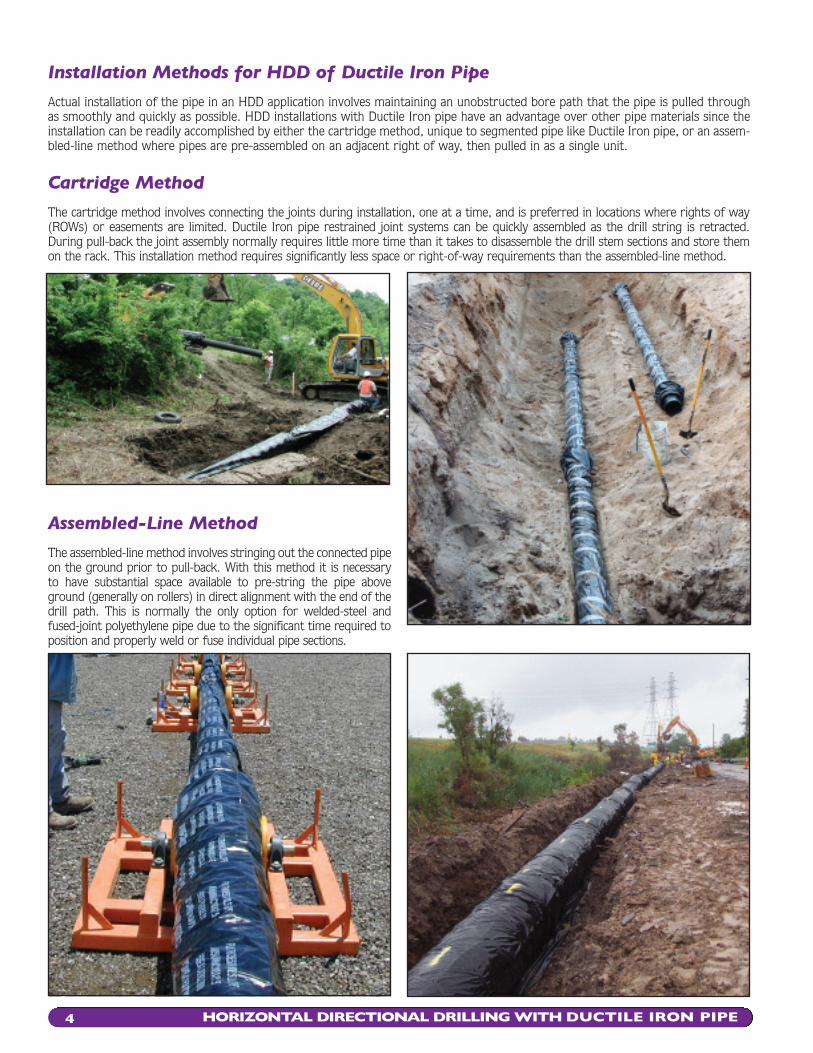
Installation Methods for HDD of Ductile Iron Pipe
Actual installation of the pipe in an HDD application involves maintaining an unobstructed bore path that the pipe is pulled throughas smoothly and quickly as possible. HDD installations with Ductile Iron pipe have an advantage over other pipe materials since theinstallation can be readily accomplished by either the cartridge method, unique to segmented pipe like Ductile Iron pipe, or an assem-bled-line method where pipes are pre-assembled on an adjacent right of way, then pulled in as a single unit.
Cartridge Method
The cartridge method involves connecting the joints during installation, one at a time, and is preferred in locations where rights of way(ROWs) or easements are limited. Ductile Iron pipe restrained joint systems can be quickly assembled as the drill string is retracted.During pull-back the joint assembly normally requires little more time than it takes to disassemble the drill stem sections and store themon the rack. This installation method requires significantly less space or right-of-way requirements than the assembled-line method.
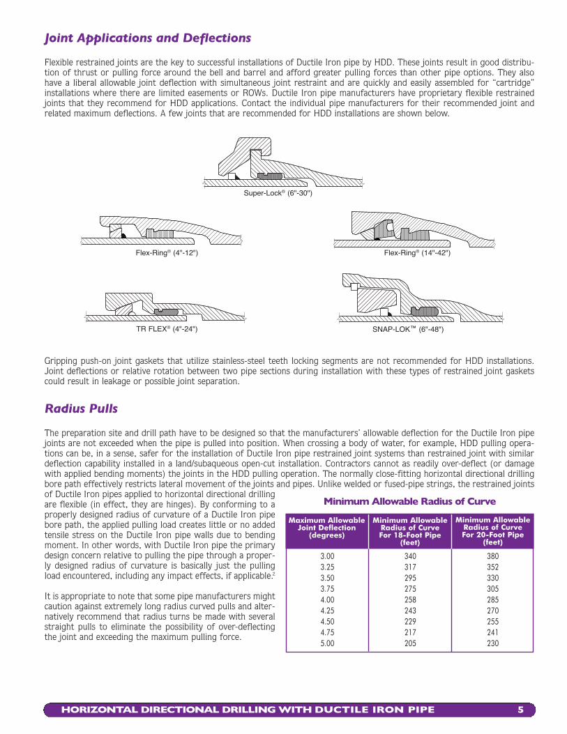
Assembled-Line Method
The assembled-line method involves stringing out the connected pipeon the ground prior to pull-back. With this method it is necessary to have substantial space available to pre-string the pipe aboveground (generally on rollers) in direct alignment with the end of thedrill path. This is normally the only option for welded-steel andfused-joint polyethylene pipe due to the significant time required toposition and properly weld or fuse individual pipe sections.
HORIZONTAL DIRECTIONAL DRILLING WITH DUCTILE IRON PIPE4
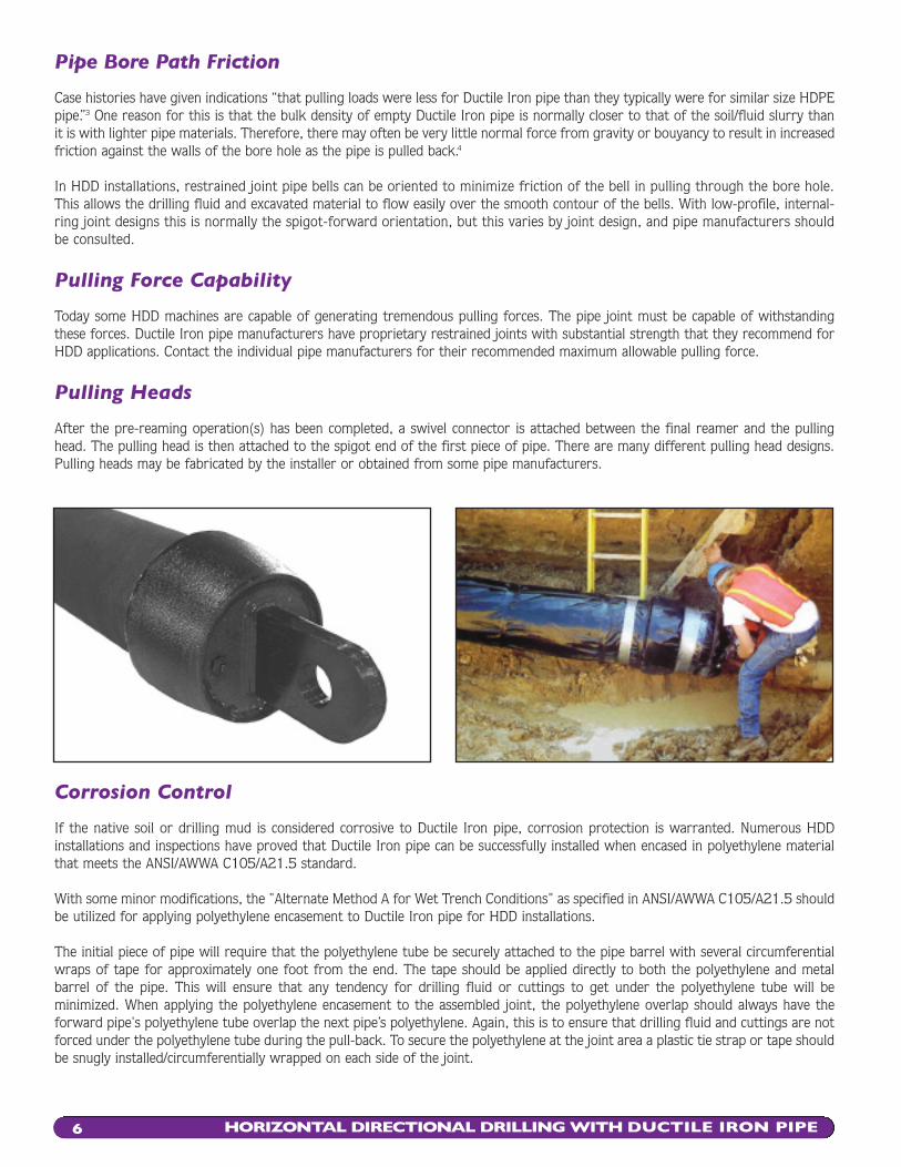
Joint Applications and Deflections
Flexible restrained joints are the key to successful installations of Ductile Iron pipe by HDD. These joints result in good distribu-tion of thrust or pulling force around the bell and barrel and afford greater pulling forces than other pipe options. They alsohave a liberal allowable joint deflection with simultaneous joint restraint and are quickly and easily assembled for “cartridge”installations where there are limited easements or ROWs. Ductile Iron pipe manufacturers have proprietary flexible restrainedjoints that they recommend for HDD applications. Contact the individual pipe manufacturers for their recommended joint andrelated maximum deflections. A few joints that are recommended for HDD installations are shown below.
Gripping push-on joint gaskets that utilize stainless-steel teeth locking segments are not recommended for HDD installations.Joint deflections or relative rotation between two pipe sections during installation with these types of restrained joint gasketscould result in leakage or possible joint separation.
HORIZONTAL DIRECTIONAL DRILLING WITH DUCTILE IRON PIPE 5
Super-Lock® (6"-30")
Flex-Ring® (4"-12")
TR FLEX® (4"-24")
Flex-Ring® (14"-42")
Radius Pulls
The preparation site and drill path have to be designed so that the manufacturers’ allowable deflection for the Ductile Iron pipejoints are not exceeded when the pipe is pulled into position. When crossing a body of water, for example, HDD pulling opera-tions can be, in a sense, safer for the installation of Ductile Iron pipe restrained joint systems than restrained joint with similardeflection capability installed in a land/subaqueous open-cut installation. Contractors cannot as readily over-deflect (or damagewith applied bending moments) the joints in the HDD pulling operation. The normally close-fitting horizontal directional drillingbore path effectively restricts lateral movement of the joints and pipes. Unlike welded or fused-pipe strings, the restrained jointsof Ductile Iron pipes applied to horizontal directional drillingare flexible (in effect, they are hinges). By conforming to aproperly designed radius of curvature of a Ductile Iron pipebore path, the applied pulling load creates little or no addedtensile stress on the Ductile Iron pipe walls due to bendingmoment. In other words, with Ductile Iron pipe the primarydesign concern relative to pulling the pipe through a proper-ly designed radius of curvature is basically just the pullingload encountered, including any impact effects, if applicable.2
It is appropriate to note that some pipe manufacturers mightcaution against extremely long radius curved pulls and alter-natively recommend that radius turns be made with severalstraight pulls to eliminate the possibility of over-deflectingthe joint and exceeding the maximum pulling force.
Minimum Allowable Radius of Curve
3.00 340 3803.25 317 3523.50 295 3303.75 275 3054.00 258 2854.25 243 2704.50 229 2554.75 217 2415.00 205 230
Maximum AllowableJoint Deflection
(degrees)
Minimum AllowableRadius of CurveFor 18-Foot Pipe
(feet)
Minimum AllowableRadius of CurveFor 20-Foot Pipe
(feet)
SNAP-LOK™ (6"-48")
HORIZONTAL DIRECTIONAL DRILLING WITH DUCTILE IRON PIPE6
Pipe Bore Path Friction
Case histories have given indications “that pulling loads were less for Ductile Iron pipe than they typically were for similar size HDPEpipe.”3 One reason for this is that the bulk density of empty Ductile Iron pipe is normally closer to that of the soil/fluid slurry thanit is with lighter pipe materials. Therefore, there may often be very little normal force from gravity or bouyancy to result in increasedfriction against the walls of the bore hole as the pipe is pulled back.4
In HDD installations, restrained joint pipe bells can be oriented to minimize friction of the bell in pulling through the bore hole.This allows the drilling fluid and excavated material to flow easily over the smooth contour of the bells. With low-profile, internal-ring joint designs this is normally the spigot-forward orientation, but this varies by joint design, and pipe manufacturers shouldbe consulted.
Pulling Force Capability
Today some HDD machines are capable of generating tremendous pulling forces. The pipe joint must be capable of withstandingthese forces. Ductile Iron pipe manufacturers have proprietary restrained joints with substantial strength that they recommend forHDD applications. Contact the individual pipe manufacturers for their recommended maximum allowable pulling force.
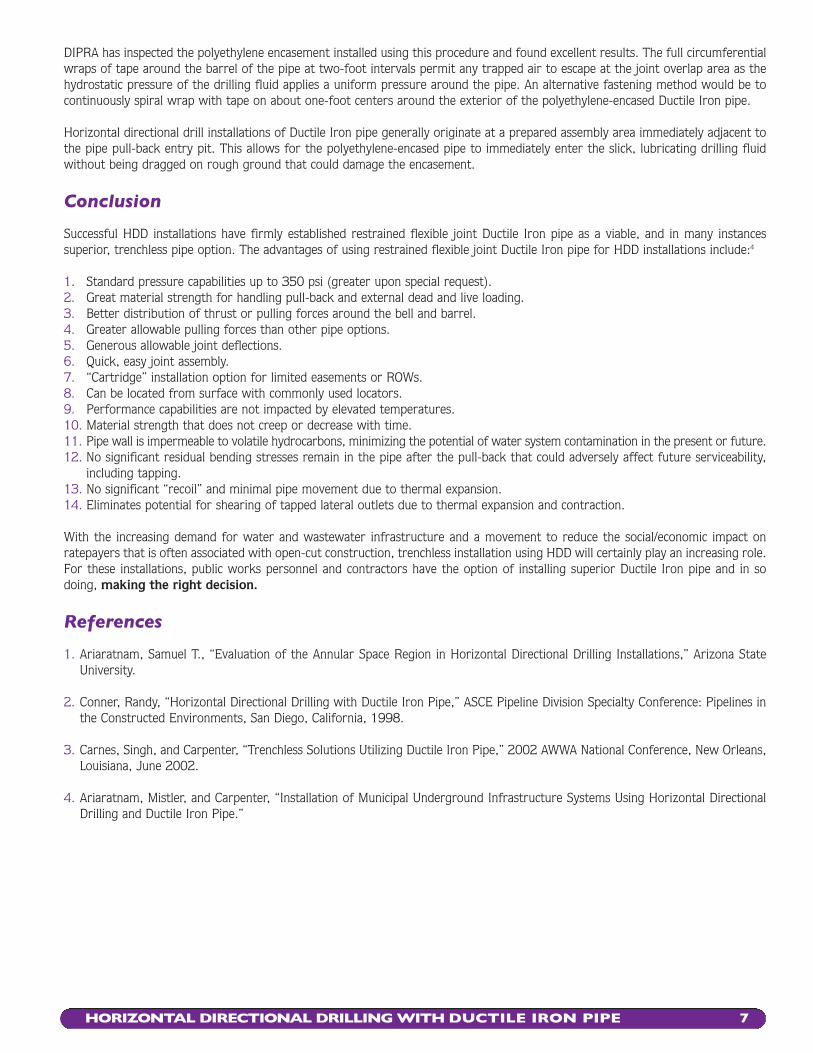
Pulling Heads
After the pre-reaming operation(s) has been completed, a swivel connector is attached between the final reamer and the pullinghead. The pulling head is then attached to the spigot end of the first piece of pipe. There are many different pulling head designs.Pulling heads may be fabricated by the installer or obtained from some pipe manufacturers.
Corrosion Control
If the native soil or drilling mud is considered corrosive to Ductile Iron pipe, corrosion protection is warranted. Numerous HDD installations and inspections have proved that Ductile Iron pipe can be successfully installed when encased in polyethylene materialthat meets the ANSI/AWWA C105/A21.5 standard.
With some minor modifications, the "Alternate Method A for Wet Trench Conditions" as specified in ANSI/AWWA C105/A21.5 shouldbe utilized for applying polyethylene encasement to Ductile Iron pipe for HDD installations.
The initial piece of pipe will require that the polyethylene tube be securely attached to the pipe barrel with several circumferentialwraps of tape for approximately one foot from the end. The tape should be applied directly to both the polyethylene and metal barrel of the pipe. This will ensure that any tendency for drilling fluid or cuttings to get under the polyethylene tube will be minimized. When applying the polyethylene encasement to the assembled joint, the polyethylene overlap should always have the forward pipe's polyethylene tube overlap the next pipe’s polyethylene. Again, this is to ensure that drilling fluid and cuttings are notforced under the polyethylene tube during the pull-back. To secure the polyethylene at the joint area a plastic tie strap or tape shouldbe snugly installed/circumferentially wrapped on each side of the joint.
HORIZONTAL DIRECTIONAL DRILLING WITH DUCTILE IRON PIPE 7
DIPRA has inspected the polyethylene encasement installed using this procedure and found excellent results. The full circumferentialwraps of tape around the barrel of the pipe at two-foot intervals permit any trapped air to escape at the joint overlap area as thehydrostatic pressure of the drilling fluid applies a uniform pressure around the pipe. An alternative fastening method would be tocontinuously spiral wrap with tape on about one-foot centers around the exterior of the polyethylene-encased Ductile Iron pipe.
Horizontal directional drill installations of Ductile Iron pipe generally originate at a prepared assembly area immediately adjacent tothe pipe pull-back entry pit. This allows for the polyethylene-encased pipe to immediately enter the slick, lubricating drilling fluidwithout being dragged on rough ground that could damage the encasement.
Conclusion
Successful HDD installations have firmly established restrained flexible joint Ductile Iron pipe as a viable, and in many instances superior, trenchless pipe option. The advantages of using restrained flexible joint Ductile Iron pipe for HDD installations include:4
1. Standard pressure capabilities up to 350 psi (greater upon special request).2. Great material strength for handling pull-back and external dead and live loading.3. Better distribution of thrust or pulling forces around the bell and barrel.4. Greater allowable pulling forces than other pipe options.5. Generous allowable joint deflections.6. Quick, easy joint assembly.7. “Cartridge” installation option for limited easements or ROWs.8. Can be located from surface with commonly used locators.9. Performance capabilities are not impacted by elevated temperatures.10. Material strength that does not creep or decrease with time.11. Pipe wall is impermeable to volatile hydrocarbons, minimizing the potential of water system contamination in the present or future.12. No significant residual bending stresses remain in the pipe after the pull-back that could adversely affect future serviceability,
including tapping.13. No significant “recoil” and minimal pipe movement due to thermal expansion.14. Eliminates potential for shearing of tapped lateral outlets due to thermal expansion and contraction.
With the increasing demand for water and wastewater infrastructure and a movement to reduce the social/economic impact onratepayers that is often associated with open-cut construction, trenchless installation using HDD will certainly play an increasing role.For these installations, public works personnel and contractors have the option of installing superior Ductile Iron pipe and in sodoing, making the right decision.
References
1. Ariaratnam, Samuel T., “Evaluation of the Annular Space Region in Horizontal Directional Drilling Installations,” Arizona StateUniversity.
2. Conner, Randy, “Horizontal Directional Drilling with Ductile Iron Pipe,” ASCE Pipeline Division Specialty Conference: Pipelines inthe Constructed Environments, San Diego, California, 1998.
3. Carnes, Singh, and Carpenter, “Trenchless Solutions Utilizing Ductile Iron Pipe,” 2002 AWWA National Conference, New Orleans,Louisiana, June 2002.
4. Ariaratnam, Mistler, and Carpenter, “Installation of Municipal Underground Infrastructure Systems Using Horizontal DirectionalDrilling and Ductile Iron Pipe.”
HDD/1-06/PDF
Revised 1-06
Manufactured from recycled materials.
American Cast Iron Pipe CompanyP.O. Box 2727Birmingham, Alabama 35202-2727
Atlantic States Cast Iron Pipe Company183 Sitgreaves StreetPhillipsburg, New Jersey 08865-3000
Canada Pipe Company, Ltd.1757 Burlington Street EastHamilton, Ontario L8N 3R5 Canada
Clow Water Systems CompanyP.O. Box 6001Coshocton, Ohio 43812-6001
McWane Cast Iron Pipe Company1201 Vanderbilt RoadBirmingham, Alabama 35234
Pacific States Cast Iron Pipe CompanyP.O. Box 1219Provo, Utah 84603-1219
United States Pipe and F oundry CompanyP.O. Box 10406Birmingham, Alabama 35202-0406
An association of quality producers dedicated to highest pipestandards through a program of continuing research.245 Riverchase Parkway East, Suite OBirmingham, Alabama 35244-1856Telephone 205 402-8700 FAX 205 402-8730http://www.dipra.org
Copyright © 200 6, 2004 by Ductile Iron Pipe Research Association. This publication, orparts thereof, may not be reproduced in any form without permission of the publishers.
DUCTILE IRON PIPER E S E A R C H A S S O C I AT I O N
DUCTILE IRON PIPE THE RIGHTD E C I S I O N
DIPRA MEMBER COMPANIES