Embed Size (px)
Citation preview

An advanced software solution for HDD design and installation of pipelines and utilities.
The New Horizontal Directional Drilling PowerTool (HDDPT) enables safe and efficient drilling, reaming, and installation of pipelines at road crossings, water bodies, and railroad right of ways.
Using HDDPT will lower construction risks and costs by providing:
� Advanced HDD design insight and planning for successful execution of all operations.
� A solution that minimizes excavation complexity and lowers cost of pipeline installation.
� Advanced borehole stability to prevent borehole collapse or washout.
� Ad Hoc operational calculations to monitor drilling/ pulling operations.
Address all HDD Applications with the latest HDDPT Technology
HDDPT is specifically developed for professionals involved in the design, engineering, and installation of pipelines and utilities by horizontal directional drilling. HDDPT can be used for the design and installation of pipelines and conduits for the following applications:
�Natural Gas
� Petroleum
�Water & Sewer Lines
�Other Fluids
� Telecommunications
� Electric Power Lines
HDDPT has all the engineering calculations needed to quickly solve HDD project challenges. The underlying mathematical models and technical procedures are based on the latest HDD technology and are following current regulations, standards and recommended practices. HDDPT addresses standard stress and pull force analysis for steel and polyethylene pipe, drilling fluid hydraulic and pressure analysis, and addresses the installation of cables in conduits.
IMPROVE DESIGN AND CONSTRUCTION OF ADVANCED HDD PROJECTS
PowerTool Functionalities
Phone: 713-630-0505 [email protected]
The advanced PowerTool functionalities are listed below:
� Dynamic Borehole Design
� GIS/Shape File Importation
� Streamlined Data importation
� Borehole Stability and Plots
� Customized HDD Project Reporting
HORIZONTAL DIRECTIONAL DRILLING PowerTool (HDDPT)
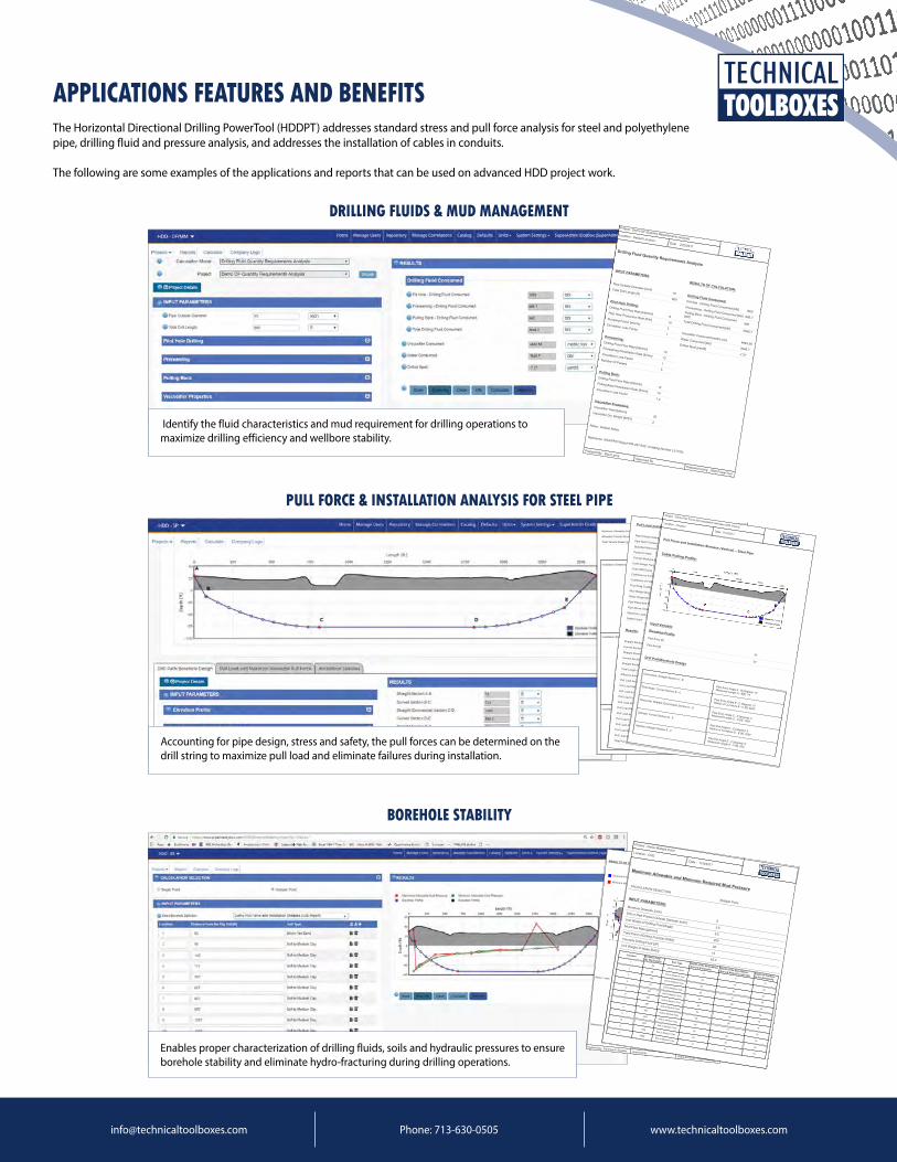
APPLICATIONS FEATURES AND BENEFITSThe Horizontal Directional Drilling PowerTool (HDDPT) addresses standard stress and pull force analysis for steel and polyethylene pipe, drilling fluid and pressure analysis, and addresses the installation of cables in conduits.
The following are some examples of the applications and reports that can be used on advanced HDD project work.
DRILLING FLUIDS & MUD MANAGEMENT
PULL FORCE & INSTALLATION ANALYSIS FOR STEEL PIPE
Phone: 713-630-0505 [email protected]
Maximum Allowable Pull Force: [lb] 248735.82 PASS
Allowable Tensile Stress [psi] 37800
Total Tensile Stress: [psi] 4330.31 PASS
Installation Stresses at Points BTensile Stress [psi] 119.13 PASS
Allowable Tensile Stress [psi] 37800
Bending Stress [psi] 0 PASS
Allowable Bending Stress [psi] 31500
Hydrostatic Mud Pressure [psi] 8.12
External Hoop Stress [psi] 62.25 PASS
Allowable Elastic Hoop Buckling[psi] 23863.81
Combined Load Interaction atPoint: B
Unity Check: Tensile andBending 0.003 PASS
Unity Check: Tensile Bendingand External Hoop 0 PASS
Installation Stresses at Points CTensile Stress [psi] 1311.51 PASS
Allowable Tensile Stress [psi] 37800
Bending Stress [psi] 1906 PASS
Allowable Bending Stress [psi] 31500
Hydrostatic Mud Pressure [psi] 47.89
External Hoop Stress [psi] 367.25 PASS
Allowable Elastic Hoop Buckling[psi] 23863.81
Combined Load Interaction atPoint: C
Unity Check: Tensile andBending 0.095 PASS
Unity Check: Tensile Bendingand External Hoop 0.0087 PASS
Installation Stresses at Points DTensile Stress [psi] 3050.15 PASS
Allowable Tensile Stress [psi] 37800
Bending Stress [psi] 0 PASS
Allowable Bending Stress [psi] 31500
Hydrostatic Mud Pressure [psi] 47.89
External Hoop Stress [psi] 367.25 PASS
Allowable Elastic Hoop Buckling 23863.81
Pull Load and Maximum Allowable Pull ForcePipe Outside Diameter [inch]
6.625
Pipe Wall Thickness [inch]
0.432
Specified Minimum Yield Strength [psi]
42000
Poisson's Ratio
0.3
Young's Modulus of Elasticity [psi]
29000000
Code Design Factor
1
Code SMYS [psi]
42000
Coefficient of Friction : Pipe - Soil(0.23 - 0.3 per Maidla)
0.3
Coefficient of Friction : Pipe - Rollers(0.1)
0.1
Fluid Drag Coefficient(0.03 - 0.05)
0.05
Mud Weight [lb/gal]
12
Water Weight [lb/ft3]
62.4
Pipe Filled With Water
No
Pipe Above Ground Section of Roller?
No
Maximum Load Factor
0.9
Safety Factor
1.2Results:
Straight Section A - B [ft]
75
Curved Section B - C [ft]
733
Straight (Downslope) Section C - D [ft]
1000
Curved Section D - E [ft]
586.4
Straight Section E - F [ft]
200
Total Length of the Borehole [ft]
2594.4
Effective Submerged Weight [lb/ft]
7.08
Pull Load Section on Rollers - Pipe Entry [lb]
0
Pull Load Straight Section A - B [lb]
1001.3
Pull Load at Point B [lb]
1001.3
Pull Load Curved Section B - C [lb]
10021.91
Pull Load at Point C [lb]
11023.2
Pull Load Straight (Downslope) Section C - D [lb]
14613.1
Pull Load at Point D [lb]
25636.3
Pull Load Curved Section D - E [lb]
7644.06
Pull Load at Point E [lb]
33280.36
Pull Load Straight Section E - F [lb]
3115.67
Pull Load at Point F [lb]
36396.03
Total Pull Load: [lb]
36396.03
Project : Demo Pull Force and Installation Stresses (GIS Import)Location : Houston
Date: 7/19/2017
Pull Force and Installation Stresses (Vertical) – Steel PipeCable Pulling Profile:
Input Variable:Elevation Profile
Pipe Entry [ft]
30
Pipe Exit [ft]
30
Drill Path/Borehole Design
Downslope: Straight Section A - B
Pipe Entry Angle A - B [degree]: 10Measured Length A - B[ft]: 75
Downslope: Curved Section B - C
Pipe Entry Angle B - C [degree]: 10Radius of Curvature B - C [ft]: 4200
Horizontal: Straight (Downslope) Section C - D
Pipe Entry Angle C - D [degree]: 0Measured Length C - D [ft]: 1000
Upslope: Curved Section D - E
Pipe Exit Angle D - E [degree]: 8Radius of Curvature D - E [ft]: 4200
Upslope: Straight Section E - F
Pipe Exit Angle E - F [degree]: 8Measured Length E - F [ft]: 200
Accounting for pipe design, stress and safety, the pull forces can be determined on the drill string to maximize pull load and eliminate failures during installation.
BOREHOLE STABILITY
RESULTS OF CALCULATION:
Borehole Profile
Elevation Profile Minimum Allowable Mud Pressure
Maximum Allowable Mud Pressure
Notes : India
Reference: Willoughby, David (2005). Horizontal Directional Drilling, McGraw-Hill, New York, ISBN 0-87814-395-5. v.
Prepared By : SuperAdmin EiceBox Approved By : Prepared Using: HDD PowerTool
Project : Demo Multiple PointLocation : CHD
Date : 11/9/2017
Maximum Allowable and Minimum Required Mud PressureCALCULATION SELECTION
Multiple PointINPUT PARAMETERS:
Borehole Diameter [inch]
6
Drill or Pipe Product Outside Diameter [inch]3.5
Unit Weight of Drilling Fluid [lb/gal]
9.5
Mud Flow Rate [gal/min]
200
Yield Point of Drilling Fluid [lb/100ft2]
28
Viscosity Drilling Fluid [cP]
14
Unit Weight of Water [lb/ft3]
62.4
Location Distance fromthe Rig Side(ft) Soil Type Depth of the Bore BelowGround Surface(ft) Depth of the Bore BelowGround Water Elevation(ft)Depth of the Boreto the Surface(ft)
163
Brown Tan Sand14
9
14
298
Soft to Medium Clay20
16
22
3145
Soft to Medium Clay28
25
32
4177
Soft to Medium Clay29
31
38
5367
Soft to Medium Clay54
59
66
6667
Soft to Medium Clay50
67
76
7867
Soft to Medium Clay53
66
76
8967
Soft to Medium Clay66
66
76
91267
Soft to Medium Clay69
71
76
101567
Soft to Medium Clay68
64
76
111768
Soft to Medium Clay45
40
76
122069
Soft to Medium Clay14
10
76Enables proper characterization of drilling fluids, soils and hydraulic pressures to ensure borehole stability and eliminate hydro-fracturing during drilling operations.
Project : Demo DF-Quantity Requirements AnalysisLocation : Default Location
Date : 2/23/2017Drilling Fluid Quantity Requirements Analysis
INPUT PARAMETERS:
Pipe Outside Diameter [inch]10
Total Drill Length [ft]
800Pilot Hole Drilling:Drilling Fluid Flow Rate [bbl/min]8
Pilot Hole Production Rate [ft/hr]10
Pumping Factor [min/hr]3
Circulation Loss Factor1
Prereaming:Drilling Fluid Flow Rate [bbl/min]
10Prereaming Penetration Rate [ft/min] 12
Circulation Loss Factor1
Number Of Passes
5Pulling Back:
Drilling Fluid Flow Rate [bbl/min]12
Pulling Back Penetration Rate [ft/min] 14Circulation Loss Factor
1.4Viscosifier Properties:Viscosifier Yield [bbl/ton]20
Viscosifier Dry Weight [lb/ft3]2
RESULTS OF CALCULATION:
Drilling Fluid Consumed:Pit Hole - Drilling Fluid Consumed [bbl] 1920Prereaming - Drilling Fluid Consumed [bbl] 666.7
Pulling Back - Drilling Fluid Consumed[bbl]
960Total Drilling Fluid Consumed [bbl]
3546.7Viscosifier Consumed [metric ton]4883.58
Water Consumed [bbl]3546.7
Drilled Spoil [yard3]
-7.27
Notes : Default Notes
Reference: AGA/PRCI Report PR-227-9321 (Catalog Number L51725)Prepared By : Raul LemaApproved By :
Prepared Using: HDD PowerTool
Identify the fluid characteristics and mud requirement for drilling operations to maximize drilling efficiency and wellbore stability.
APPLICATIONS FEATURES AND BENEFITS
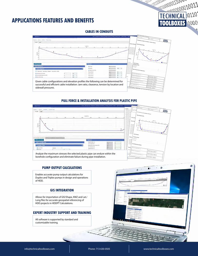
PULL FORCE & INSTALLATION ANALYSIS FOR PLASTIC PIPE
Phone: 713-630-0505 [email protected]
Results:Straight Section A - B [ft] 115
Curved Section B - C [ft] 174
Straight (Downslope) Section C - D [ft] 1620
Curved Section D - E [ft] 209
Straight Section E - F [ft] 81
Total Length of the Borehole [ft] 2199.9
Effective Submerged Weight [lb/ft] 20.44
Bending Strain 0
Bending Stress [psi] 20.66
Pull Load Section on Rollers - Pipe Entry 0
Pull Load Straight Section A - B [lb] 379.85
Pull Load at Point B [lb] 379.85
Pull Load Curved Section B - C [lb] 812.74
Pull Load at Point C [lb] 1192.59
Pull Load Straight (Downslope) Section C - D [lb] 8761.2
Pull Load at Point D [lb] 9953.78
Pull Load Curved Section D - E [lb] 1515.06
Pull Load at Point E [lb] 11468.85
Pull Load Straight Section E - F [lb] 952.12
Pull Load at Point F [lb] 12420.96
Total Pull Load [lb] 12420.96
Allowable/Safe Tensile Stress [psi] 1079.34
Axial Tensile Stress at Point: A [psi] 0 PASS
Axial Tensile Stress at Point: B [psi] 19.76 PASS
Axial Tensile Stress at Point: C [psi] 103.37 PASS
Axial Tensile Stress at Point: D [psi] 517.79 PASS
Axial Tensile Stress at Point: E [psi] 637.93 PASS
Axial Tensile Stress at Point F : [psi] 646.13 PASS
Breakaway Links Settings [lbf] 21146.1
Static Head Pressure [psi] 2.92
Maximum Pressure During Pullback [psi] 7.92
Ovality Compensation Factor 0.35
Tensile Reduction Factor 0.24
Critical Collapse Pressure [psi] 42.66
Safety Factor Against Collapse 5.38
Notes :
Reference: Willoughby, David (2005). Horizontal Directional Drilling, McGraw-Hill, New York, ISBN 0-87814-395-5. v.
Prepared By : Approved By : Prepared Using: HDD PowerTool
Upslope: Curved Section D - E
Pipe Exit Angle D - E [degree]: 12Radius of Curvature D - E [ft]: 1000Upslope: Straight Section E - F
Pipe Exit Angle E - F [degree]: 12Measured Length E - F [ft]: 81
Pull Load and Maximum Allowable Pull Force
Pipe Properties
Pipe Outside Diameter [inch]
8.625
Pipe Wall Thickness [inch]
0.78
Poisson's Ratio
0.45
Long Term Modulus of Elasticity [psi]
28200
24 hr Modulus of Elasticity [psi]
57500
Allowable/Safe pull Stress [psi]
1100
Coefficient of Friction : Pipe - Rollers(0.1)
0.1
Specific Gravity of the Pipe Material
0.95
Pipe Filled With Water
YesWater and Mud Properties
Mud Weight [lb/gal]
1.6
Water Weight [lb/ft3]
62.2
Hydrokinetic Pressure [psi]
5
Coefficient of Friction : Pipe - Soil(0.23 - 0.3 per Maidla)
0.1
Fluid Drag Coefficient(0.03 - 0.05)
0.01Borehole
Borehole Diameter [inch]
12.9375
Project : Demo PE - Pull Force and Installation Stresses (Dynamic Borehole
Design)
Location : Houston
Date : 6/17/2017
PE- Pull Force and Installation StressesPipe Pulling Profile:
Input Variable:
Elevation ProfilePipe Entry [ft]
0
Pipe Exit [ft]
0 Drill Path/Borehole Design
Downslope: Straight Section A - B
Pipe Entry Angle A - B [degree]: 10Measured Length A - B[ft]: 115
Downslope: Curved Section B - C
Pipe Entry Angle B - C [degree]: 10Radius of Curvature B - C [ft]: 1000
Horizontal: Straight (Downslope) Section C - D
Pipe Entry Angle C - D [degree]: 0Measured Length C - D [ft]: 1620
PUMP OUTPUT CALCULATIONS
GIS INTEGRATION
EXPERT INDUSTRY SUPPORT AND TRAINING
Enables accurate pump output calculations for Duplex and Triplex pumps in design and operations of HDD.
Allows for importation of GIS/Shape, KMZ and Lat./Long files for accurate geospatial referencing of HDD projects in HDDPT Calculations.
All software is supported by standard and customizable training.
Analyze the maximum stresses the selected plastic pipe can endure within the borehole configuration and eliminate failure during pipe installation.
CABLES IN CONDUITS
Cable Configuration
CableConfigurationType
Single CableInside Diameter of Conduit/Pipe [inch]
9Nominal Outside Diameter of One Cable [inch]
2Cable or Cables Weight [lbf/ft]
3Tension from the Cable Reel to Pipe Entrance [lbf] 120Dynamic Coefficient of Friction
3
Results:
Jam Ratio
4.5Clearance [inch]
6.9Weight Correction Factor
1Tension at Point B [lbf]:
884.54Tension at Point C [lbf]:
1344.73Tension at Point D [lbf]:
2154.23Tension at Point E [lbf]:
3054.23Tension at Point F [lbf]:
5432.98Tension at Point G [lbf]:
6559.09Sidewall Pressure [psi]
1.47
Notes :
Reference: EIC CG5 2005 ' Underground Extruded Power Cable Pulling Guide' 2nd Edition
Prepared By : SuperAdmin EiceBox Approved By : Prepared Using: HDD PowerTool
Project : Demo Installation of Conduit PipesLocation : Houston
Date : 5/12/2017Installation of Cables in Conduits – Tension Analysis
Cable Pulling Profile:
Input Variable:Elevation ProfilePipe Entry [ft]
0
Pipe Exit [ft]
0
Cable Pulling Profile Configuration
Downslope: Straight Section A - B
Pipe Entry Angle A - B [degree]: 8Measured Length A - B [ft]: 90
Downslope: Curved Section B - C
Pipe Entry Angle B - C [degree]: 8Radius of Curvature B - C [ft]: 600
Downslope: Curved Section C - D
Pipe Entry Angle C - D [degree]: 9Radius of Curvature C - D [ft]: 600
Horizontal: Straight (Downslope) Section D - EPipe Entry Angle D - E [degree]: 0Measured Length D - E [ft]: 100
Upslope: Curved Section E - F
Pipe Exit Angle E - F [degree]: 11Radius of Curvature E - F [ft]: 600
Upslope: Straight Section F - G
Pipe Exit Angle F - G [degree]: 10Measured Length F - G [ft]: 120
Given cable configurations and elevation profiles the following can be determined for successful and efficient cable installation: Jam ratio, clearance, tension by location and sidewall pressures.

Disclaimer: This document is provided for information purposes only and the contents hereof are subject to change without notice. This document is not warranted to be error-free, nor subject to any other warranties or conditions, whether expressed orally or implied in law, including implied warranties and conditions of merchantability or fitness for a particular purpose. We specifically disclaim any liability with respect to this document and no contractual obligations are formed either directly or indirectly by this document. This document may not be reproduced or transmitted in any form or by any means, electronic or mechanical, for any purpose, without our prior written permission.
Technical Toolboxes and Horizontal Directional Drilling PowerTool (HDDPT) are registered trademarks of Technical Toolboxes. Other names may be trademarks of their respective owners.
The Industry Standard for Over 20 Years
Toll Free: 1-866-866-6766Phone: 713-630-0505
www.technicaltoolboxes.com
CONTACT US
Horizontal Directional Drilling PowerTool System Specifications
Version 2018.04A (skyBox)1. Windows 7 and above2. Google Chrome3. Internet Explorer version 10 and above4. Internet Connection
3801 Kirby Drive, Suite 520, Houston, Texas 77098Sales: [email protected] | Support: [email protected]
Images provided by Mears Group, Inc. HDD/DP Division