Embed Size (px)
Citation preview

MEl... HOLTEC INTERNATIONAL
Holtec Center, 555 Lincoln Drive West, Marlton, NJ 08053
Telephone (856) 797-0900
Fax (856) 797-0909
February 20, 2002
U.S. Nuclear Regulatory Commission ATTN: Document Control Desk Washington, DC 20555-0001
Subject: USNRC Docket No. 72-1014 HI-STORM 100 Certificate of Compliance 1014 Alternatives to Codes and Standards
References: 1. Holtec Project 5014 2. NRC letter to Holtec, Request for Additional Information - Holtec HI-STORM
100 ASME Code Exceptions, dated February 8, 2002. 3. Holtec letter to NRC, Code Alternatives for HI-STORM 100 System, dated
February 4, 2002
Dear Sir:
We have received and reviewed the request for additional information (RAI) (Reference 2) pertaining to our recent request for new and revised alternatives to the ASME Code requirements for our HI-STORM 100 System (Reference 3). Attachment 1 to this letter contains the individual RAI questions and responses. Attachment 2 to this letter contains the table of new and revised ASME Code alternatives (Table 1 from Reference 3), modified as indicated in the RAI responses, with new text in italics and deleted text removed. This table replaces Table 1 in Reference 3 in its entirety. Table 2 in Reference 3 remains applicable.
If you have any questions or require additional information, please contact the undersigned at (856)
797-0900, extension 668.
Sincerely,
Brian Gutherman, P Licensing Manager
Approved:
K'P. Singh, P.E., Ph.D. President and CEO
C
mMENEM HOLTEC INTERNATIONAL
U. S. Nuclear Regulatory Commission ATTN: Document Control Desk Document ID 5014450 Page 2 of 2
Concurrence:
Manufacturing
Holtec Center, 555 Lincoln Drive West, Marlton, NJ 08053
Telephone (856) 797-0900 Fax (856) 797-0909
12 W0ý Quality Assurance
emcc: Mr. Timothy Kobetz, USNRC (w/attach.) Holtec Group 1 (w/attach.) Holtec NRC Correspondence Distribution (w/attach.) HUG Licensing Committee (w/attach.)
Document ID: 5014450
Attachments: 1. RAI questions and responses 2. Proposed revised HI-STORM 100 System ASME Code alternatives

M*N EMm Holtec Center, 555 Lincoln Drive West, Marlton, NJ 08053 Telephone (856) 797-0900
H O L T E C Fax (856) 797-0909 INTERNATIONAL
U. S. Nuclear Regulatory Commission ATTN: Document Control Desk Document ID 5014450 Attachment 1 Page 1 of 5
REQUEST FOR ADDITIONAL INFORMATION QUESTIONS AND HOLTEC RESPONSES
Question 1
Subsection NCA: Clarify or remove the statement that "Requirements that are not germane to meeting the applicable Code stress limits are not applicable to its certification for cask use under 10 CFR 72."
In the context the statement is used in the request, it is unclear which requirements are not germane to meeting the applicable Code stress limits. This information is required to assure compliance with 10 CFR 72.236(b).
Response 1
The statement has been deleted from the table.
Question 2
NB-2000, NG-2000, and NF-2000: Clarify why the statements regarding the Holtec Quality Assurance (QA) program were added.
The use of the Holtec QA program is used to ensure appropriate implementation of the ASME Code requirements under 10 CFR Part 72, however, the program is not part of any ASME Codes. This information is required to assure compliance with 10 CFR 72.236(b).
Response 2
The additional statements were proposed in an attempt to clarify that material purchased commercially and dedicated for use in important-to-safety applications were also acceptable as an alternative to meeting the NB, NG, and NF-2000 requirements. In light of the NRC's question, we have re-reviewed the proposed clarifying statements. We agree that this detail pertaining to material procurement implementation is part of the NRC-approved QA program and not directly related to compliance with the Code. Since these were the only proposed changes to these previously approved alternatives, we have removed them from the attached table and from the scope of this request. They will remain, as currently written and approved, in Table 3-1 of Appendix B to the HISTORM 100 CoC.
M*N EM-- Holtec Center, 555 Lincoln Drive West, Marlton, NJ 08053 Telephone (856) 797-0900
H O L T E C Fax (856) 797-0909 INTERNATIONAL
U. S. Nuclear Regulatory Commission ATTN: Document Control Desk Document ID 5014450 Attachment 1 Page 2 of 5
Question 3
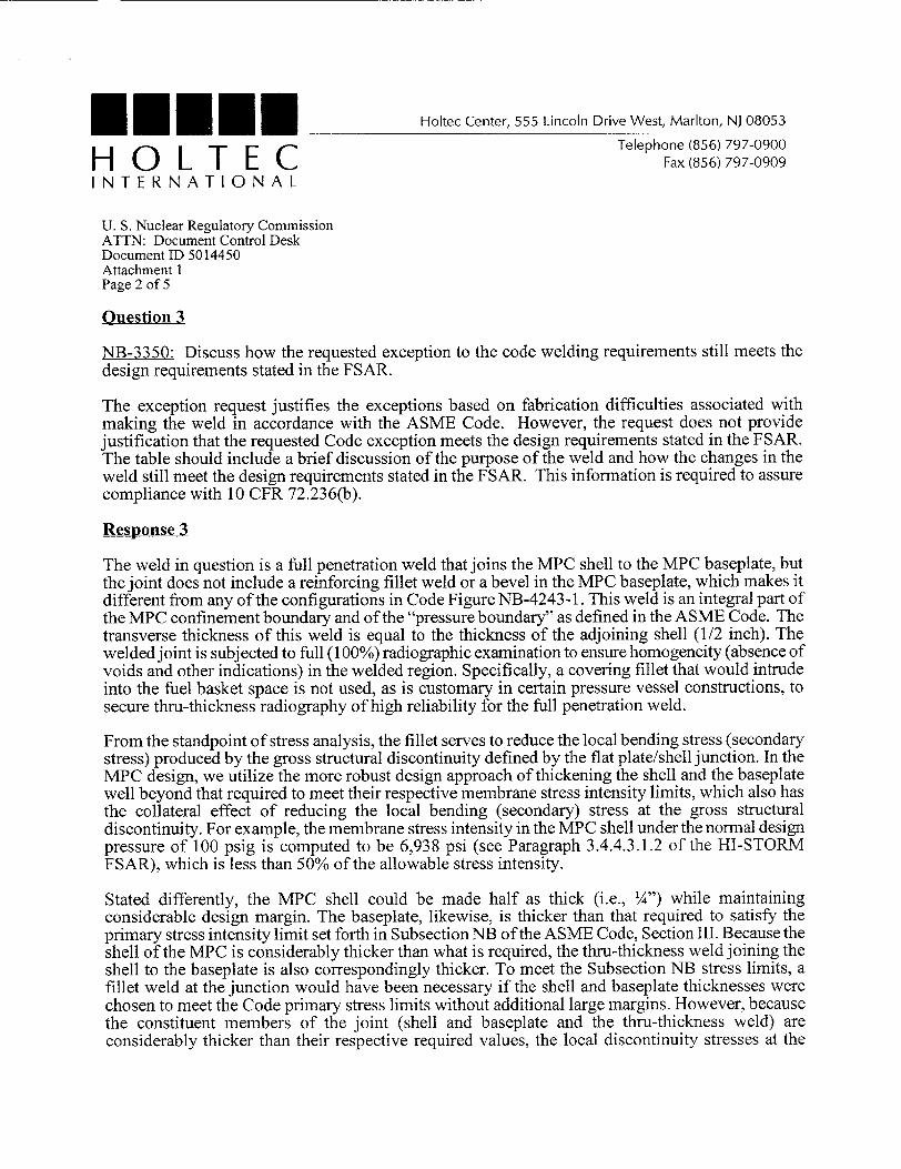
NB-3350: Discuss how the requested exception to the code welding requirements still meets the design requirements stated in the FSAR.
The exception request justifies the exceptions based on fabrication difficulties associated with making the weld in accordance with the ASME Code. However, the request does not provide justification that the requested Code exception meets the design requirements stated in the FSAR. The table should include a brief discussion of the purpose of the weld and how the changes in the weld still meet the design requirements stated in the FSAR. This information is required to assure compliance with 10 CFR 72.236(b).
Response 3
The weld in question is a full penetration weld that joins the MPC shell to the MPC baseplate, but the joint does not include a reinforcing fillet weld or a bevel in the MPC baseplate, which makes it different from any of the configurations in Code Figure NB-4243-1. This weld is an integral part of the MPC confinement boundary and of the "pressure boundary" as defined in the ASME Code. The transverse thickness of this weld is equal to the thickness of the adjoining shell (1/2 inch). The welded joint is subjected to full (100%) radiographic examination to ensure homogeneity (absence of voids and other indications) in the welded region. Specifically, a covering fillet that would intrude into the fuel basket space is not used, as is customary in certain pressure vessel constructions, to secure thru-thickness radiography of high reliability for the full penetration weld.
From the standpoint of stress analysis, the fillet serves to reduce the local bending stress (secondary stress) produced by the gross structural discontinuity defined by the flat plate/shell junction. In the MPC design, we utilize the more robust design approach of thickening the shell and the baseplate well beyond that required to meet their respective membrane stress intensity limits, which also has the collateral effect of reducing the local bending (secondary) stress at the gross structural discontinuity. For example, the membrane stress intensity in the MPC shell under the normal design pressure of 100 psig is computed to be 6,938 psi (see Paragraph 3.4.4.3.1.2 of the HI-STORM FSAR), which is less than 50% of the allowable stress intensity.
Stated differently, the MPC shell could be made half as thick (i.e., ¼") while maintaining considerable design margin. The baseplate, likewise, is thicker than that required to satisfy the primary stress intensity limit set forth in Subsection NB of the ASME Code, Section III. Because the shell of the MPC is considerably thicker than what is required, the thru-thickness weld joining the shell to the baseplate is also correspondingly thicker. To meet the Subsection NB stress limits, a fillet weld at the junction would have been necessary if the shell and baseplate thicknesses were chosen to meet the Code primary stress limits without additional large margins. However, because the constituent members of the joint (shell and baseplate and the thru-thickness weld) are considerably thicker than their respective required values, the local discontinuity stresses at the

M E N EM Holtec Center, 555 Lincoln Drive West, Marlton, NJ 08053 Telephone (856) 797-0900
H O L T E C Fax (856) 797-0909 INTERNATIONAL
U. S. Nuclear Regulatory Commission ATTN: Document Control Desk Document ID 5014450 Attachment 1 Page 3 of 5
junction are well within the Code limits as documented in the HI-STAR 100 and HI-STORM 100 FSARs.
Specifically, the stress analysis for the MPC is contained in the HI-STAR 100 System FSAR (Docket 72-1008) and referred to from the HI-STORM 100 System FSAR. The load combinations for the MPC confinement boundary are defined in Table 3.1.4 of the HI-STAR 100 FSAR. This table contains cross-references to the text elsewhere in the FSAR that describes the analysis and results. These include FSAR Section 3.4.4.3.1 and Appendices 3.1, 3.H, and 3.AA. As shown in HISTAR 100 FSAR Appendix 3.1, the lowest margin of safety occurs under the accident condition (60 g's and 125 psig internal pressure) and is 28.8%. Therefore, the baseplate-to-shell weld joint (as represented in the FSAR drawings) has a substantial margin of safety. Elsewhere in the MPC, the margins are even greater because of the design decision made to thicken the pressure boundary (shell and plate members) beyond that required to meet the Code.
The proposed Code alternative has been modified to clarify the justification.
Question 4
NG-4420: Provide the analysis that demonstrates how the design margins stated in the FSAR are maintained by the new weld design criteria.
The justification states that "The acceptance criteria provided in the foregoing have been established to comport with the objectives of the basket design and preserve the margins demonstrated in the supporting design analysis." However, no reference to previous or new analysis is provided. This information is required to assure compliance with 10 CFR 72.236(b).
Response 4
The weld deviation acceptance criteria stated in this Code alternative are not new criteria. These acceptance criteria have been on the MPC drawings and part of the supporting design in the FSAR since initial certification of the HI-STAR 100 and HI-STORM 100 Systems.
From the structural standpoint, the weld acceptance criteria are established to ensure that any departure from the ideal, continuous fillet weld seam would not alter the primary bending stresses on which the design of the fuel baskets is predicated. Stated differently, the permitted weld discontinuities are limited in size to ensure that they remain classifiable as local stress elevators ("peak stress", F, in the ASME Code for which specific stress intensity limits do not apply).
Appendix 3.M of the HI-STAR 100 System FSAR (Docket 72-1008) determines the required MPC basket panel-to-panel fillet weld size based on maintaining a safety factor greater than 1.0 in the

l l l l l Holtec Center, 555 Lincoln Drive West, Marlton, NJ 08053 Telephone (856) 797-0900
H O L T E C Fax (856) 797-0909 INTERNATIONAL
U. S. Nuclear Regulatory Commission ATTN: Document Control Desk Document ID 5014450 Attachment 1 Page 4 of 5
welds as well as in the storage cell walls. Appendix 3.M reports minimum safety factors, under worst case accident conditions, of 1.56 and 1.71 for the MPC-68 and MPC-32, respectively. These safety factors are for local membrane plus primary bending stresses. Local weld deviations as allowed by the proposed alternative produce stresses that are not of the "primary" genre (i.e., not required to satisfy equilibrium). This Code alternative does not alter these safety factors. We also note that the weld efficiency factor of 0.35 used in the stress analysis in HI-STAR 100 FSAR Appendix 3.M contemplates a weld joint with possible minor flaws and discontinuities.
The proposed Code alternative has been modified to clarify the justification.
Question 5
NB-4120, NG-4120, and NF-4120: Clarify when tensile or impact testing is required for material subjected to heat treatment during fabrication or installation. This information is required to assure compliance with 10 CFR 72.236(b).
Response 5
The ASME Code is quite prescriptive in specifying Post Weld Heat Treatment (PWHT) requirements for parts whose tensile or fracture resistance properties are considered to be potentially degraded to the extent they require a remedial thermal operation. The governing parameters typically are thickness of the welded part, size of the weld, and the metallurgical characteristics of the material. We do not seek any alternative from the Code's heat treatment requirements. This alternative is intended to provide clarification regarding what operations constitute heat treatment where the Code fails to provide any guidance.
Specifically, it pertains to in-shop manufacturing activities that are common to cask components (such as lead pouring), but rather rare in the general pressure vessel industry. Accordingly, the objective of this Code alternative is to clarify the term "heat treatment" as it is applied in the Code for the fabrication of HI-STORM 100 System certified components. Heating of material during normal fabrication evolutions is considered "heat treatment", requiring tensile or impact testing, only if the metal temperature has been raised above its off-normal temperature (as listed in FSAR Chapter 2) and held above that threshold in excess of 24 hours. The 24 hour limit typifies a bounding value for normal manufacturing activities which, by definition, are short duration events.

M mMm Holtec Center, 555 Lincoln Drive West, Marlton, NJ 08053 Telephone (856) 797-0900
H O L T E C Fax (856) 797-0909 INTERNATIONAL
U. S. Nuclear Regulatory Commission ATTN: Document Control Desk Document ID 5014450 Attachment I Page 5 of 5
Question 6
NF-4441: Provide justification for eliminating the references to specific margins of safety and deceleration limits in the justification for this exception.
The exception request eliminated margins of safety and deceleration limits that had been previously reviewed and approved by the staff. This information is required to assure compliance with 10 CFR 72.236(b).
Response 6
The inclusion of the specific factors of safety (12 and 6) in the Code alternative table is unnecessary to justify the alternative. While the applicable welds continue to have safety factors that meet these values, requiring minimum safety factors of 12 and 6 via this alternative poses an unnecessary and inappropriate restriction on making future design changes under 10 CFR 72.48 that may slightly reduce these safety factors while maintaining significant safety margins. The Code requirement for safety factor in these welded joints is 1.0 (i.e., any margin above 1.0 is acceptable and Codecompliant). In other words, any margin in excess of the safety factor of unity is not required to fulfill the requirements of the Code and is, therefore, entirely voluntary. The prescription in the Code alternative table should be consistent with the Code. The deceleration limit of 45 g's is controlled elsewhere in the CoC (Appendix B, Section 3.4.6 of preliminary Revision 1 to the CoC) and requires prior NRC review and approval to alter. Therefore, including this specific value in the Code exception table would be redundant and, therefore, unnecessary.

MEl... HOLTEC INTERNATIONAL
Holtec Center, 555 Lincoln Drive West, Marlton, NJ 08053
Telephone (856) 797-0900 Fax (856) 797-0909
U. S. Nuclear Regulatory Commission ATTN: Document Control Desk Document ID 5014450 Attachment 2 Page 1 of 5
Table 1
PROPOSED NEW AND REVISED ASME CODE ALTERNATIVES FOR THE HI-STORM 100 SYSTEM
Reference Component ASME Code Code Requirement Exception, Justification, & Compensatory Measures
Section/Article MPC, MPC Subsection NCA General Requirements. Because the MPC, overpack, and transfer cask are not ASME basket Requires preparation of a Code stamped vessels, none of the specifications, reports, assembly, HI- Design Specification, Design certificates, or other general requirements specified by NCA STORM Report, Overpressure are required. In lieu of a Design Specification and Design overpack steel Protection Report, Report, the HI-STORM FSAR includes the design criteria, structure, and Certification of Construction service conditions, and load combinations for the design and HI-TRAC Report, Data Report, and operation of the HI-STORM 100 System as well as the transfer cask other administrative controls results of the stress analyses to demonstrate that applicable steel structure. for an ASME Code stamped Code stress limits are met. Additionally, the fabricator is not
vessel, required to have an ASME-certified QA program. All important-to-safety activities are governed by the NRCapproved Holtec QA program.
Because the cask components are not certified to the Code, the terms "Certificate Holder" and "Inspector" are not germane to the manufacturing of NRC-certified cask components. To eliminate ambiguity, the responsibilities assigned to the Certificate Holder in the various articles of Subsections NB, NG, and NF of the Code, as applicable, shall be interpreted to apply to the NRC Certificate of Compliance (CoG) holder (and by extension, to the component fabricator) if the requirement must be fulfilled. The Code term "Inspector" means the QA/QC personnel of the CoC holder and its vendors assigned to oversee and inspect the manufacturing process.

'IENEE HOLTEC INTERNATIONAL
Holtec Center, 555 Lincoln Drive West, Marlton, NJ 08053
Telephone (856) 797-0900 Fax (856) 797-0909
U. S. Nuclear Regulatory Commission ATTN: Document Control Desk Document ID 5014450 Attachment 2 Page 2 of 5
Reference Component ASME Code Code Requirement Exception, Justification, & Compensatory Measures
Section/Article MPC basket NB-1130 NB-1132.2(d) requires that The MPC basket supports (nonpressure-retaining structural supports and the first connecting weld of a attachment)and lift lugs (nonstructural attachments used lift lugs nonpressure-retaining exclusively for lifting an empty MPC) are welded to the
structural attachment to a inside of the pressure-retaining MPC shell, but are not component shall be designed in accordance with Subsection NB. The basket considered part of the supports and associated attachment welds are designed to component unless the weld is satisfy the stress limits of Subsection NG and the lift lugs and more than 2t from the associated attachment welds are designed to satisfy the stress pressure-retaining portion of limits of Subsection NF, as a minimum. These attachments the component, where t is the and their welds are shown by analysis to meet the respective nominal thickness of the stress limits for their service conditions. Likewise, nonpressure-retaining material, structural items, such as shield plugs, spacers, etc. if used,
can be attached to pressure-retaining parts in the same NB-i 132.2(e) requires that manner. the first connecting weld of a welded nonstructural attachment to a component shall conform to NB-4430 if the connecting weld is within 2t from the pressureretaining portion of the component.
MPC, MPC NB-3100 Provides requirements for These requirements are not applicable. The HI-STORM basket NG-3 100 determining design loading FSAR, serving as the Design Specification, establishes the assembly, HI- NF-3 100 conditions, such as pressure, service conditions and load combinations for the storage STORM temperature, and mechanical system. overpack, and loads. HI-TRAC transfer cask MPC NB-3350 NB-3352.3 requires, for The MPC shell-to-baseplate weld joint design (designated
Category C joints, that the Category C) does not include a reinforcing fillet weld or a minimum dimensions of the bevel in the MPC baseplate, which makes it different than welds and throat thickness any of the representative configurations depicted in Figure shall be as shown in Figure NB-4243-1. The transverse thickness of this weld is equal to NB-4243-1. the thickness of the adjoining shell (1/2 inch). The weld is
designed as a full penetration weld that receives VT and RT or UT, as well as final surface PT examinations. Because the MPC shell design thickness is considerably larger than the minimum thickness required by the Code, a reinforcing fillet weld that would intrude into the MPC cavity space is not included. Not including this fillet weld provides for a higher quality radiographic examination of the full penetration weld.
From the standpoint of stress analysis, the fillet weld serves to reduce the local bending stress (secondary stress) produced by the gross structural discontinuity defined by the flat plate/shell junction. In the MPC design, the shell and baseplate thicknesses are well beyond that required to meet their respective membrane stress intensity limits.

I.'.' HOLTEC INTERNATIONAL
Holtec Center, 555 Lincoln Drive West, Marlton, NJ 08053
Telephone (856) 797-0900 Fax (856) 797-0909
U. S. Nuclear Regulatory Commission ATTN: Document Control Desk Document ID 5014450 Attachment 2 Page 3 of 5
Reference Component ASME Code Code Requirement Exception, Justification, & Compensatory Measures
Section/Article MPC, HI- NB-4220 Requires certain forming The cylindricity measurements on the rolled shells are not STORM NF-4220 tolerances to be met for specifically recorded in the shop travelers, as would be the overpack steel cylindrical, conical, or case for a Code-stamped pressure vessel. Rather, the structure, HI- spherical shells of a vessel, requirements on inter-component clearances (such as the TRAC transfer MPC-to-transfer cask) are guaranteed through fixturecask steel controlled manufacturing. The fabrication specification and structure shop procedures ensure that all dimensional design
objectives, including inter-component annular clearances are satisfied. The dimensions required to be met in fabrication are chosen to meet the functional requirements of the dry storage components. Thus, although the post-forming Code cylindricity requirements are not evaluated for compliance directly, they are indirectly satisfied (actually exceeded) in the final manufactured components.
MPC basket NG-4420 NG-4427(a) requires a fillet Modify the Code requirement (intended for core support assembly weld in any single structures) with the following text prepared to accord with
continuous weld may be less the geometry and stress analysis imperatives for the fuel than the specified fillet weld basket: For the longitudinal MPC basket fillet welds, the dimension by not more than following criteria apply: 1) The specified fillet weld throat 1/16 inch, provided that the dimension must be maintained over at least 92 percent of the total undersize portion of the total weld length. All regions of undersized weld must be weld does not exceed 10 less than 3 inches long and separated from each other by at percent of the length of the least 9 inches. 2) Areas of undercuts and porosity beyond weld. Individual undersize that allowed by the applicable ASME Code shall not exceed weld portions shall not 1/2 inch in weld length. The total length of undercut and exceed 2 inches in length. porosity over any 1-foot length shall not exceed 2 inches. 3)
The total weld length in which items (1) and (2) apply shall not exceed a total of 10 percent of the overall weld length. The limited access of the MPC basket panel longitudinal fillet welds makes it difficult to perform effective repairs of these welds and creates the potential for causing additional damage to the basket assembly (e.g., to the neutron absorber and its sheathing) if repairs are attempted. The acceptance criteria provided in the foregoing have been established to comport with the objectives of the basket design and preserve the margins demonstrated in the supporting stress analysis.
From the structural standpoint, the weld acceptance criteria are established to ensure that any departure from the ideal, continuous fillet weld seam would not alter the primaiy bending stresses on which the design of the .fuel baskets is predicated. Stated differently, the permitted weld discontinuities are limited in size to ensure that they remain classifiable as local stress elevators ('peak stress ", F, in the ASME Code for which specific stress intensity limits do not apply).
mMENEM HOLTEC INTERNATIONAL
Holtec Center, 555 Lincoln Drive West, Marlton, NJ 08053
Telephone (856) 797-0900 Fax (856) 797-0909
U. S. Nuclear Regulatory Commission ATTN: Document Control Desk Document ID 5014450 Attachment 2 Page 4 of 5
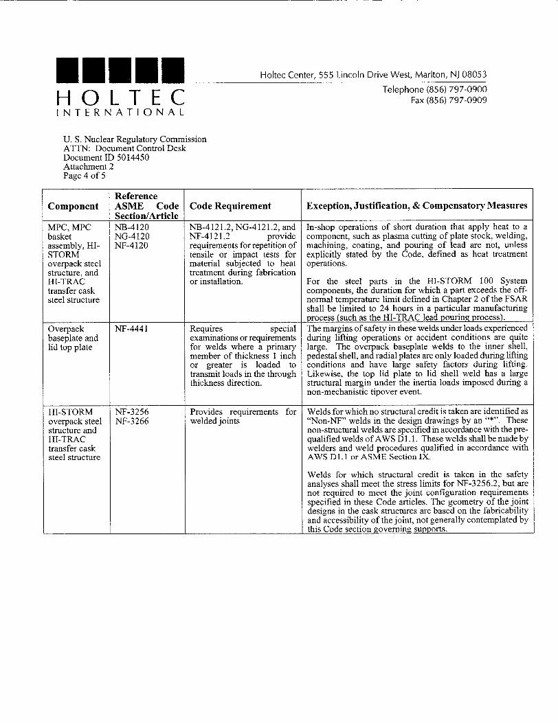
Reference Component ASME Code Code Requirement Exception, Justification, & Compensatory Measures
Section/Article MPC, MPC NB-4120 NB-4121.2, NG-4121.2, and In-shop operations of short duration that apply heat to a basket NG-4120 NF-4121.2 provide component, such as plasma cutting of plate stock, welding, assembly, HI- NF-4120 requirements for repetition of machining, coating, and pouring of lead are not, unless STORM tensile or impact tests for explicitly stated by the Code, defined as heat treatment overpack steel material subjected to heat operations. structure, and treatment during fabrication HI-TRAC or installation. For the steel parts in the HI-STORM 100 System transfer cask components, the duration for which a part exceeds the offsteel structure normal temperature limit defined in Chapter 2 of the FSAR
shall be limited to 24 hours in a particular manufacturing process (such as the HI-TRAC lead pouring process).
Overpack NF-4441 Requires special The margins of safety in these welds under loads experienced baseplate and examinations or requirements during lifting operations or accident conditions are quite lid top plate for welds where a primary large. The overpack baseplate welds to the inner shell,
member of thickness 1 inch pedestal shell, and radial plates are only loaded during lifting or greater is loaded to conditions and have large safety factors during lifting. transmit loads in the through Likewise, the top lid plate to lid shell weld has a large thickness direction. structural margin under the inertia loads imposed during a
non-mechanistic tipover event.
HI-STORM NF-3256 Provides requirements for Welds for which no structural credit is taken are identified as overpack steel NF-3266 welded joints "Non-NF" welds in the design drawings by an "*". These structure and non-structural welds are specified in accordance with the preHI-TRAC qualified welds ofAWS D1. 1. These welds shall be made by transfer cask welders and weld procedures qualified in accordance with steel structure AWS Dl. 1 or ASME Section IX.
Welds for which structural credit is taken in the safety analyses shall meet the stress limits for NF-3256.2, but are not required to meet the joint configuration requirements specified in these Code articles. The geometry of the joint designs in the cask structures are based on the fabricability and accessibility of the joint, not generally contemplated by this Code section governing supports.
MEu..' HOLTEC INTERNATIONAL
Holtec Center, 555 Lincoln Drive West, Marlton, NJ 08053
Telephone (856) 797-0900 Fax (856) 797-0909
U. S. Nuclear Regulatory Commission ATTN: Document Control Desk Document ID 5014450 Attachment 2 Page 5 of 5
Reference Component ASME Code Code Requirement Exception, Justification, & Compensatory Measures
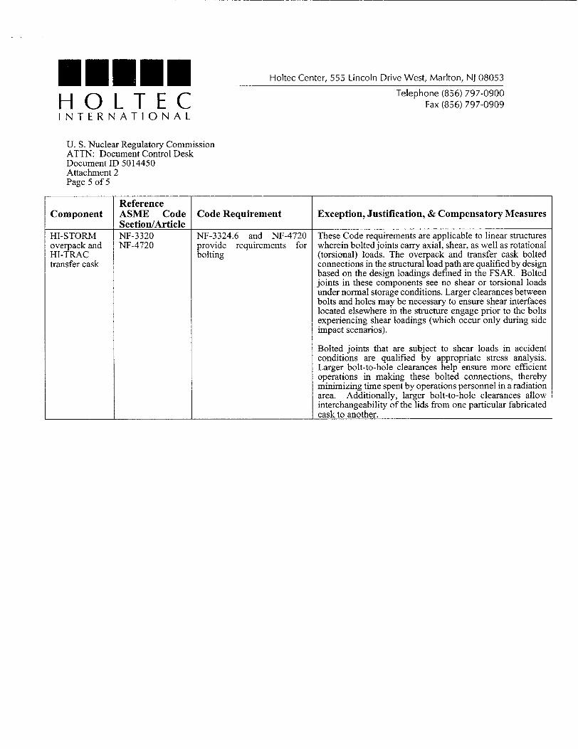
Section/Article HI-STORM NF-3320 NF-3324.6 and NF-4720 These Code requirements are applicable to linear structures overpack and NF-4720 provide requirements for wherein bolted joints carry axial, shear, as well as rotational HI-TRAC bolting (torsional) loads. The overpack and transfer cask bolted transfer cask connections in the structural load path are qualified by design
based on the design loadings defined in the FSAR. Bolted joints in these components see no shear or torsional loads under normal storage conditions. Larger clearances between bolts and holes may be necessary to ensure shear interfaces located elsewhere in the structure engage prior to the bolts experiencing shear loadings (which occur only during side impact scenarios).
Bolted joints that are subject to shear loads in accident conditions are qualified by appropriate stress analysis. Larger bolt-to-hole clearances help ensure more efficient operations in making these bolted connections, thereby minimizing time spent by operations personnel in a radiation area. Additionally, larger bolt-to-hole clearances allow interchangeability of the lids from one particular fabricated cask to another.