Embed Size (px)
Citation preview
Holographic Beam Forming and MIMO
Holographic Beam Forming and MIMO
By Eric J. Black, PhD, CTO, Pivotal Commware
Demand Drives Spectral Efficiency
Mobile subscribers continue to demonstrate an insatiable demand for data. The next decade will
experience the full impact of next generation 5G cellular networks with gigabit throughput, low-latency,
and connectivity to billions of devices (IoT). The explosive demand for wireless access will surpass the data
transfer capacity of existing broadband links.
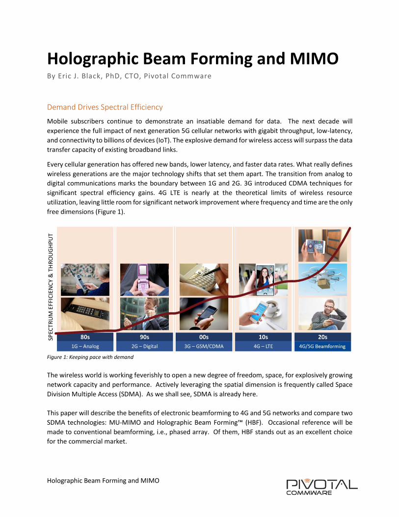
Every cellular generation has offered new bands, lower latency, and faster data rates. What really defines
wireless generations are the major technology shifts that set them apart. The transition from analog to
digital communications marks the boundary between 1G and 2G. 3G introduced CDMA techniques for
significant spectral efficiency gains. 4G LTE is nearly at the theoretical limits of wireless resource
utilization, leaving little room for significant network improvement where frequency and time are the only
free dimensions (Figure 1).
Figure 1: Keeping pace with demand
The wireless world is working feverishly to open a new degree of freedom, space, for explosively growing
network capacity and performance. Actively leveraging the spatial dimension is frequently called Space
Division Multiple Access (SDMA). As we shall see, SDMA is already here.
This paper will describe the benefits of electronic beamforming to 4G and 5G networks and compare two
SDMA technologies: MU-MIMO and Holographic Beam Forming™ (HBF). Occasional reference will be
made to conventional beamforming, i.e., phased array. Of them, HBF stands out as an excellent choice
for the commercial market.
Page 2 of 8
Holographic Beam Forming and MIMO
Beamforming
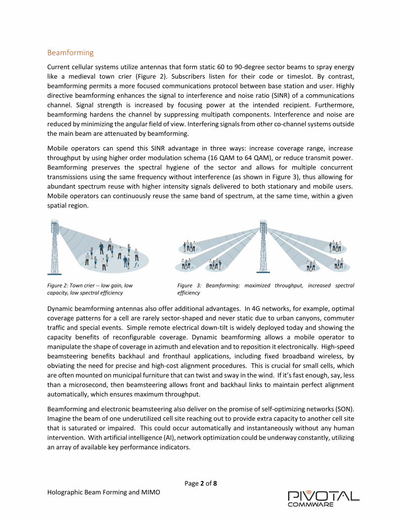
Current cellular systems utilize antennas that form static 60 to 90-degree sector beams to spray energy
like a medieval town crier (Figure 2). Subscribers listen for their code or timeslot. By contrast,
beamforming permits a more focused communications protocol between base station and user. Highly
directive beamforming enhances the signal to interference and noise ratio (SINR) of a communications
channel. Signal strength is increased by focusing power at the intended recipient. Furthermore,
beamforming hardens the channel by suppressing multipath components. Interference and noise are
reduced by minimizing the angular field of view. Interfering signals from other co-channel systems outside
the main beam are attenuated by beamforming.
Mobile operators can spend this SINR advantage in three ways: increase coverage range, increase
throughput by using higher order modulation schema (16 QAM to 64 QAM), or reduce transmit power.
Beamforming preserves the spectral hygiene of the sector and allows for multiple concurrent
transmissions using the same frequency without interference (as shown in Figure 3), thus allowing for
abundant spectrum reuse with higher intensity signals delivered to both stationary and mobile users.
Mobile operators can continuously reuse the same band of spectrum, at the same time, within a given
spatial region.
Figure 2: Town crier -- low gain, low Figure 3: Beamforming: maximized throughput, increased spectral capacity, low spectral efficiency efficiency
Dynamic beamforming antennas also offer additional advantages. In 4G networks, for example, optimal
coverage patterns for a cell are rarely sector-shaped and never static due to urban canyons, commuter
traffic and special events. Simple remote electrical down-tilt is widely deployed today and showing the
capacity benefits of reconfigurable coverage. Dynamic beamforming allows a mobile operator to
manipulate the shape of coverage in azimuth and elevation and to reposition it electronically. High-speed
beamsteering benefits backhaul and fronthaul applications, including fixed broadband wireless, by
obviating the need for precise and high-cost alignment procedures. This is crucial for small cells, which
are often mounted on municipal furniture that can twist and sway in the wind. If it’s fast enough, say, less
than a microsecond, then beamsteering allows front and backhaul links to maintain perfect alignment
automatically, which ensures maximum throughput.
Beamforming and electronic beamsteering also deliver on the promise of self-optimizing networks (SON).
Imagine the beam of one underutilized cell site reaching out to provide extra capacity to another cell site
that is saturated or impaired. This could occur automatically and instantaneously without any human
intervention. With artificial intelligence (AI), network optimization could be underway constantly, utilizing
an array of available key performance indicators.

Page 3 of 8
Holographic Beam Forming and MIMO
But that’s today. What about 5G? The space dimension used by beamforming, as opposed to frequency
and time, is already employed in 4G networks with the concept of a cell. Wireless systems are responsible
for fixed areas of coverage and attempt to optimally use the frequency/time resources available on a per-
cell basis. The boundaries between cells where the antenna coverage overlaps are contested and so
intercell interference coordination (ICIC) is used. A cell-based system must waste resources on ICIC for
the users present in areas of overlap and thus never reaches ideal data rates.
5G will herald the widespread use of dynamic SDMA because software will be able to manipulate SDMA
antennas and their coverage patterns. This Software-Defined Antenna (SDA) is game changing. Once
coverage areas can be adjusted at digital speeds it becomes possible to shift the regions of intercell
interference to locations where no users are present. This in turn allows the cell to dedicate its full
throughput to users within its coverage area. This concept could be taken to an extreme level in 5G, where
the wireless system will employ beamforming to generate personal “cells” on a nearly per-user basis. Each
beam will have uncontested access to the full wireless resource set and thus enable the explosive growth
in wireless capacity needed for 5G. Each SDMA beam will have capacity exceeding current 4G macrocells.
Two significant technologies are aimed at enabling these advanced beamforming capabilities: Massive
Multi-User MIMO and HBF.
MIMO Techniques
MIMO comes in many flavors and it is worthwhile to define a simple taxonomy for them. We will define
boundaries between MIMO basics which are common to all MIMO platforms, Single User or SU-MIMO
and Multi User or MU-MIMO. The term Massive-MIMO has been used with both SU and MU systems and
really just means ‘lots of radios’ with no clear delineation between what is ‘massive’ and what is not.
MIMO Basics MIMO is a digital signal processing technique that is agnostic to the physical hardware upon which it is
implemented. Indeed, MIMO’s greatest strength is in generally maximizing the capacity of a given wireless
implementation. This is also a weakness in that it is possible to select antenna configurations that the
MIMO algorithm will be unable to do anything with at all!
MIMO and ‘MIMO-like’ devices abound. However, true MIMO systems share three common
characteristics. First, all MIMO devices are composed of multiple antenna elements which are, at the
minimum, backed with a digital to analog converter (DAC), analog to digital converter (ADC), or both.
Their waveforms either directly synthesized or digitized and then up or down converted. All beam
processing takes place in the digital domain.
Secondly, MIMO relies on channel reciprocity for computation of transmit coefficients (channel sounding).
This reciprocity dependence brings a few key caveats:
1. MIMO relies heavily on time division duplexing (TDD). The large frequency division duplexing (FDD)
band splits commonly used in modern cellular band allocations do not show sufficient reciprocity
under general conditions to function.
2. MIMO is range-limited. Excessive time of flight for RF propagation leads to a time evolution in the
channel that breaks reciprocity. This is usually a non-issue in low frequency cellular applications but
is a problem for high gain, long range communication systems.
Page 4 of 8
Holographic Beam Forming and MIMO
3. High frequency millimeter wave (mmW) bands do not easily support MIMO because the channel
evolves too quickly. The channel coherence time is proportional to wavelength employed and the
inversely proportional speed of objects in the coverage area. At 30 GHz with a car moving at 5 m/s,
the channel can move from peak to null in 2 milliseconds (ms). The channel would then need to be
re-characterized to assure reciprocity less than once every 1 ms. The MIMO system would be stuck
channel sounding and never sending data with such rapid channel evolution.
Finally, MIMO supposedly does not rely on diversity strategies, but in real systems, MIMO relies on
diversity all the time. In theory, the capacity of a MIMO system is linearly proportional to the number of
antenna pairs “N” and the only requirement to achieve this capacity is a “sufficiently rich scattering
environment” that carries the critical task of assuring the orthogonality of the N channels. Understanding
what a sufficiently rich scattering environment is and how rare it is to find one – typically never -- is central
to understanding the challenges seen in MIMO systems.
SU-MIMO Single User MIMO is widely deployed in cellular networks today but interestingly, most of its benefits
come from classic polarization diversity. In SU-MIMO, multiple antennas are present both at the base
station and end user to maximize data rate between them.
In commercial 2x2 SU-MIMO (two antennas in the handset and two at the base station) deployments, the
two antenna ports are connected to small arrays with orthogonal polarizations. Frequently a left-slant and
right-slant configuration are used. This polarization diversity scheme predates MIMO by over 100 years
and has long been known to nearly double the capacity of a wireless system as the two polarizations are
orthogonal from the outset. MIMO algorithms can easily exploit this configuration but it is worth noting
that MIMO baseband processing is not required at all to achieve this capacity doubling!
SU-MIMO is also commonly encountered in home wireless routers with multiple (commonly three)
antennas. One would hope that MIMO would achieve 3x capacity in such a slow-moving, “rich scattering
environment” as the home. These systems rarely even achieve 2x as few end users bother to make sure
the three antennas are configured orthogonally. In-the-home multipath scattering alone is apparently not
rich enough.
4x4 SU-MIMO is currently seeing deployment in 4G systems but the results have been disappointing. One
expects another doubling in capacity for a 4x4 system over a 2x2 system but most reports show only 50%
extra capacity. This is exactly in line with a non-MIMO dual polarized antenna array that just doubled its
gain on both ends of the link (and thus could employ a denser coding rate).
Many far-field experiments have shown that SU-MIMO slips into a transmission mode referred to as ‘max
eigenmode transmission’ under most practical scenarios. In this mode, all power is dedicated to the
primary channel (or first two channels in a dual polarized system) that correspond to line-of-sight between
the two antenna platforms. This mode is the mathematically equivalent of classic RF analog beamforming
with the capacity scaling logarithmically with antenna gain. Without an engineered scattering
environment, far field SU-MIMO does not appear to have any advantage over conventional, i.e., phased
array, beamforming.
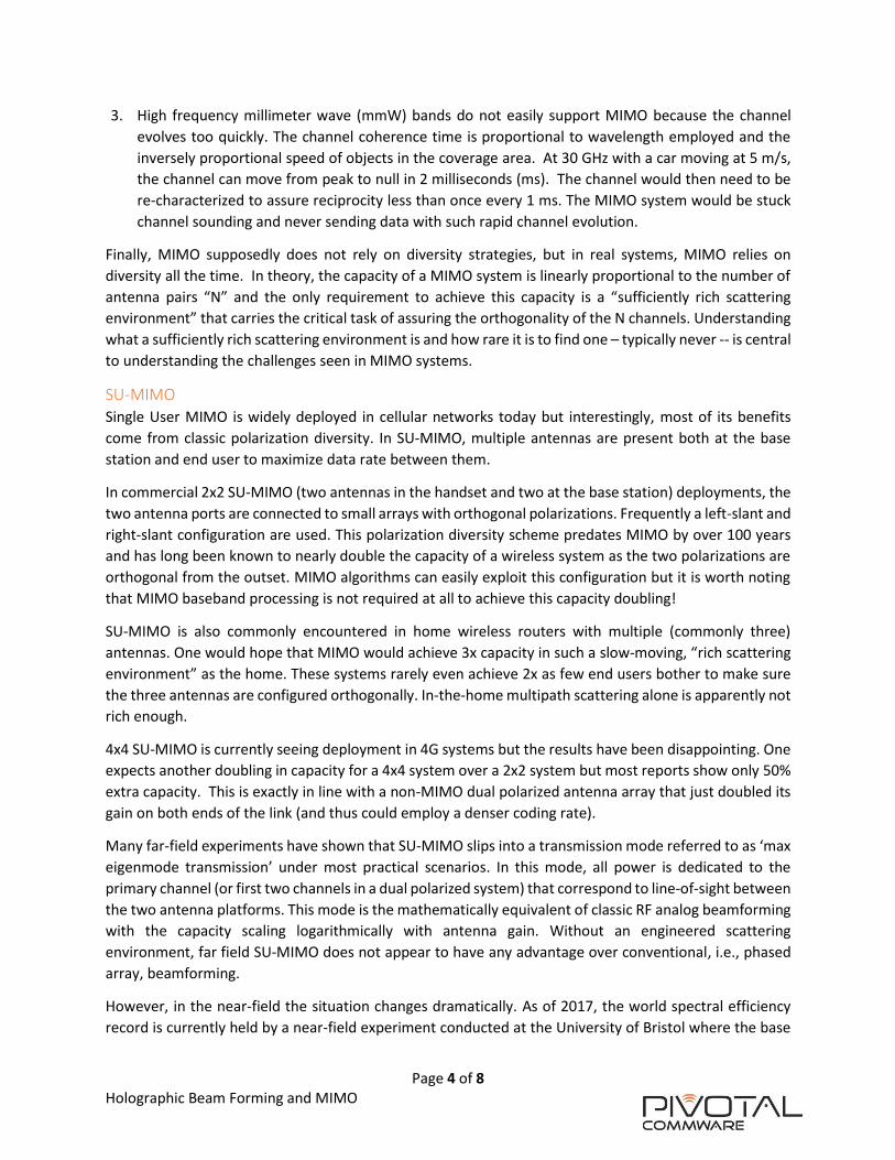
However, in the near-field the situation changes dramatically. As of 2017, the world spectral efficiency
record is currently held by a near-field experiment conducted at the University of Bristol where the base
Page 5 of 8
Holographic Beam Forming and MIMO
station and UE are within the a few feet of each another (Figure 4). Both antenna arrays are colossal
relative to their separation. In the near-field, beam focusing is possible and the coding mechanisms in
MIMO can fully exploit this situation resulting in measured spectral efficiencies greater than 130 bps/Hz.
While this result is very exciting, the lack of applicability to far field systems such as cellular suggest SU-
MIMO has maxed out.
Figure 4: University of Bristol MIMO testbed
MU-MIMO MU-MIMO systems are sometimes referred to as “Massive MIMO” but this is a misnomer as SU-MIMO
may also use large numbers of elements. The key distinction between SU and MU-MIMO is that MU-
MIMO generates unique data streams simultaneously to multiple users. One stream is dedicated to each
user device and receives unique data. This technique allows the MU-MIMO system to scale its capacity up
to multiple users provided that the users are sufficiently separated.
MU-MIMO is not without challenges. One issue is that the sidelobes of one data beam become
interference to other data beams. A technique called ‘zero-forcing’ has emerged that attempts to mitigate
this issue by forcing a radiation null for all beams (other than the desired one) in the direction of other
users. This technique is mathematically similar to adaptive nulling strategies used in phased array systems
for interference suppression. Just as with adaptive nulling, finer control is needed as the number of nulling
targets increases to maintain high suppression ratios.
Practical MU-MIMO demos have shown that it is difficult to achieve linear capacity gain high radio count.
In practice, the observed capacity gains have been more like 1/10th the number of radio/antenna pairs.
The reason for this is obvious. Users are rarely spaced on an angularly uniform grid thus using so many
radios is overkill. Reducing the radio/antenna count does not help as the beams widen, exacerbating the
problem.
More recently, attention has been drawn to MU-MIMO power consumption in cellular bands. Multi-GHz
clockrate 8-bit Analog to Digital Converters (ADC) require significant power (as much as 4 Watts!). For a
128 element MU-MIMO array this implies at least half a kilowatt of power needed just for the ADC
Page 6 of 8
Holographic Beam Forming and MIMO
components. The dissipated thermal load is substantial which in turn drives cooling requirements,
resulting in a heavy, bulky, power hungry and costly system for MU-MIMO. It remains an open question
if the cost of 128 radio chains is justifiable for 10x improvement. This situation does not get better at
mmW bands where even larger arrays are needed for sufficient antenna gain while power amplifier
efficiencies plummet at 60 GHz.
Research into MU-MIMO is ongoing and has recently focused on “Hybrid MIMO”. Hybrid MIMO uses
fewer DSP radios than the number of elements. The additional elements use more conventional
beamforming schemes to augment MIMO. For example, elevation beamsteering might be phased array
based while azimuth steering might be MIMO based. This has the potential to reduce cost, size, weight,
and power consumption of MU-MIMO systems. However, the obvious penalty is the increasing complexity
of such “hybrids”. Simple, cost effective methods of beamforming are desperately needed for hybrid
MIMO schema to be viable. They become even more critical at mmW where DSP radios have difficulty
with direct waveform synthesis and MIMO is not an option at all.
Holographic Beam Forming
Holographic Beam Forming™ is a new dynamic beamforming technique using a Software Defined Antenna
(SDA) that employs the lowest C-SWaP (Cost, Size, Weight, and Power) architecture available. It is
substantially different than conventional phased arrays or MIMO systems.
HBFs are passive electronically steered antennas (PESAs) that use no active amplification internally. This
leads to symmetric transmit and receive characteristics for HBF antennas. However, HBFs are distinct from
Phased Array type PESAs. HBFs do not use discrete phase shifters to accomplish beam steering by the
antenna. Instead, beamforming is accomplished using a hologram. This is a very different operating mode
than a traditional phased array and warrants some explanation.
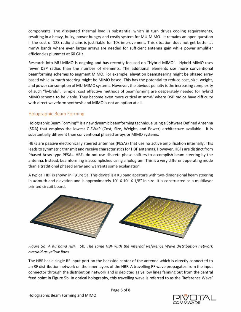
A typical HBF is shown in Figure 5a. This device is a Ku band aperture with two-dimensional beam steering
in azimuth and elevation and is approximately 10” X 10” X 1/8” in size. It is constructed as a multilayer
printed circuit board.
Figure 5a: A Ku band HBF. 5b: The same HBF with the internal Reference Wave distribution network
overlaid as yellow lines.
The HBF has a single RF input port on the backside center of the antenna which is directly connected to
an RF distribution network on the inner layers of the HBF. A travelling RF wave propagates from the input
connector through the distribution network and is depicted as yellow lines fanning out from the central
feed point in Figure 5b. In optical holography, this travelling wave is referred to as the ‘Reference Wave’

Page 7 of 8
Holographic Beam Forming and MIMO
and it is this wave we wish to transform into a desired beam. The desired beam shape is referred to as the
‘Object Wave’ in optical parlance. The ‘Hologram’ is then the structure that will transfer energy from the
Reference Wave into the Object Wave.
Adjacent to the distribution network is a carefully designed set of radiating antenna sub-elements. The
coupling between the Reference Wave and these elements (and thus the Object Wave) is varied by use of
a single varactor per antenna sub-element. The varactors are also located on the backside of the array
with control and interface electronics. Careful DC bias of the varactor changes the impedance seen by the
reference wave at each element. This impedance pattern is the Hologram and can be calculated directly
from knowledge of the provided Reference Wave and the desired Object Wave. Figures 6a and 6b show
two different digital overlays on the HBF representing the bias states of the varactors (the Hologram). The
Hologram in 6a steers an RF beam in one direction while the Hologram in 6b steers the beam to broadside.
Figure 6a: HBF with color overlay of the hologram used to steer the beam off broadside. 6b: HBF with color
overlay of the Hologram used to steer the beam to broadside.
All components used in the construction of HBF antennas are high volume commercial off the shelf (COTS)
parts. These incredibly low-cost control components take advantage of their widespread use in handsets,
leading to economies of scale that bespoke silicon implementations can only dream of. Equally important,
the beam pointing function is accomplished using a large array of reverse biased varactor diodes. This
leads to a nearly negligible power draw by the antenna’s pointing operations. Most HBFs need only USB
or PoE levels of power to operate. This then eliminates the need for active or passive cooling solutions
and drives a significant size and weight reduction.
As mentioned, MIMO uses antenna/radio pairs to achieve beamforming with a very complex baseband
unit coordinating the system. Phased arrays are simpler in that only a phase shifter and amplifier(s) are
needed for each antenna element. Control is relatively straightforward for phased arrays. Holographic
beamformers have similarly simple control and use more densely packed antenna arrays. Roughly 2.5-3x
as many elements are used by HBF systems. Fortunately for HBF, the control elements needed are trivially
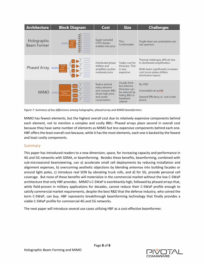
priced. These differences are summarized in Figure 7.
Page 8 of 8
Holographic Beam Forming and MIMO
Figure 7: Summary of key differences among holographic, phased array and MIMO beamformers
MIMO has fewest elements, but the highest overall cost due to relatively expensive components behind
each element, not to mention a complex and costly BBU. Phased arrays place second in overall cost
because they have same number of elements as MIMO but less expensive components behind each one.
HBF offers the least overall cost because, while it has the most elements, each one is backed by the fewest
and least costly components.
Summary
This paper has introduced readers to a new dimension, space, for increasing capacity and performance in
4G and 5G networks with SDMA, or beamforming. Besides these benefits, beamforming, combined with
sub-microsecond beamsteering, can a) accelerate small cell deployments by reducing installation and
alignment expenses, b) overcoming aesthetic objections by blending antennas into building facades or
around light poles, c) introduce real SON by obviating truck rolls, and d) for 5G, provide personal cell
coverage. But none of these benefits will materialize in the commercial market without the low C-SWaP
architecture that only HBF provides. MIMO’s C-SWaP is exorbitantly high, followed by phased arrays that,
while field-proven in military applications for decades, cannot reduce their C-SWaP profile enough to
satisfy commercial market requirements, despite the best R&D that the defense industry, who coined the
term C-SWaP, can buy. HBF represents breakthrough beamforming technology that finally provides a
viable C-SWaP profile for commercial 4G and 5G networks.
The next paper will introduce several use cases utilizing HBF as a cost-effective beamformer.