Embed Size (px)
Citation preview
Hitachi Virtual Storage PlatformPerformance Guide
MK-90RD7020-13
Document Organization
Product Version
Getting Help
Contents
© 2010-2016 Hitachi Ltd. All rights reserved.
No part of this publication may be reproduced or transmitted in any form or by any means,electronic or mechanical, including photocopying and recording, or stored in a database or retrievalsystem for any purpose without the express written permission of Hitachi, Ltd. (hereinafter referredto as "Hitachi"), and Hitachi Data Systems Corporation (hereinafter referred to as "Hitachi DataSystems").
Hitachi and Hitachi Data Systems reserve the right to make changes to this document at any timewithout notice and assume no responsibility for its use. This document contains the most currentinformation available at the time of publication. When new or revised information becomesavailable, this entire document will be updated and distributed to all registered users.
All of the features described in this document may not be currently available. Refer to the mostrecent product announcement or contact your local Hitachi Data Systems sales office for informationabout feature and product availability.
Notice: Hitachi Data Systems products and services can be ordered only under the terms andconditions of Hitachi Data Systems' applicable agreements. The use of Hitachi Data Systemsproducts is governed by the terms of your agreements with Hitachi Data Systems.
Hitachi is a registered trademark of Hitachi, Ltd., in the United States and other countries. HitachiData Systems is a registered trademark and service mark of Hitachi in the United States and othercountries.
ShadowImage and TrueCopy are registered trademarks of Hitachi Data Systems.
AIX, FICON, FlashCopy, IBM, MVS/ESA, MVS/XA, OS/390, S/390, VM/ESA, VSE/ESA, z/OS, zSeries,z/VM, and zVSE are registered trademarks or trademarks of International Business MachinesCorporation.
All other trademarks, service marks, and company names are properties of their respective owners.
Microsoft product screen shots reprinted with permission from Microsoft Corporation.
iiHitachi Virtual Storage Platform Performance Guide

Contents
Preface.................................................................................................. ixIntended audience..................................................................................................... xProduct version..........................................................................................................xDocument revision level..............................................................................................xChanges in this revision..............................................................................................xReferenced documents.............................................................................................. xiDocument organization..............................................................................................xiDocument conventions..............................................................................................xiiConvention for storage capacity values......................................................................xiiiAccessing product documentation.............................................................................xivGetting help............................................................................................................ xivComments.............................................................................................................. xiv
1 Performance overview...........................................................................1-1Hitachi Performance Monitor overview .....................................................................1-2Server Priority Manager overview.............................................................................1-2
Performance of high-priority hosts..................................................................... 1-2Upper-limit control............................................................................................1-3Threshold control............................................................................................. 1-3
Cache Residency Manager overview......................................................................... 1-3Prestaging data in cache................................................................................... 1-4Priority mode (read data only)...........................................................................1-5Bind mode (read and write data)....................................................................... 1-6
Virtual Partition Manager overview........................................................................... 1-7
2 Interoperability of Performance Monitor and other products.....................2-1Cautions and restrictions for monitoring................................................................... 2-2Cautions and restrictions for usage statistics.............................................................2-2Using Server Priority Manager..................................................................................2-3
3 Monitoring WWNs.................................................................................3-1Viewing the WWNs that are being monitored............................................................ 3-2Adding new WWNs to monitor................................................................................. 3-2Removing WWNs to monitor....................................................................................3-2
iiiHitachi Virtual Storage Platform Performance Guide
Adding WWNs to ports............................................................................................ 3-3Editing the WWN nickname..................................................................................... 3-3Connecting WWNs to ports......................................................................................3-4Deleting unused WWNs from monitoring targets....................................................... 3-4
4 Monitoring CUs.....................................................................................4-1Displaying CUs to monitor....................................................................................... 4-2Adding and removing CUs to monitor....................................................................... 4-2Confirming the status of CUs to monitor .................................................................. 4-3
5 Monitoring operation.............................................................................5-1Performing monitoring operations............................................................................ 5-2Starting monitoring................................................................................................. 5-2Stopping monitoring................................................................................................5-2
6 Setting statistical storage ranges............................................................6-1About statistical storage ranges............................................................................... 6-2
Viewing statistics.............................................................................................. 6-2Setting the storing period of statistics.......................................................................6-2
7 Working with graphs.............................................................................7-1Basic operation ......................................................................................................7-3Objects that can be displayed in graphs .................................................................. 7-4Usage rates of MPs ................................................................................................ 7-6Usage rate of a data recovery and reconstruction processor.......................................7-6Usage rate of cache memory................................................................................... 7-7Write pending statistics........................................................................................... 7-7Access paths usage statistics................................................................................... 7-8Throughput of storage system................................................................................. 7-9Size of data transferred......................................................................................... 7-11Response times.....................................................................................................7-12Cache hit rates......................................................................................................7-13Back-end performance.......................................................................................... 7-15Hard disk drive usage statistics.............................................................................. 7-16Hard disk drive access rates...................................................................................7-16ShadowImage usage statistics............................................................................... 7-17Detailed information of resources on top 20 usage rates..........................................7-18
8 Changing display of graphs....................................................................8-1Graph operation......................................................................................................8-2Changing displayed items........................................................................................ 8-2Changing a display period........................................................................................8-2Adding a new graph ...............................................................................................8-3Deleting graph panel...............................................................................................8-3
9 Server Priority Manager operations........................................................ 9-1Overview of Server Priority Manager operations........................................................ 9-2If one-to-one connections link HBAs and ports..........................................................9-2
ivHitachi Virtual Storage Platform Performance Guide
If many-to-many connections link HBAs and ports.....................................................9-5Port tab operations............................................................................................... 9-10
Analyzing traffic statistics................................................................................ 9-10Setting priority for ports on the storage system.................................................9-11Setting upper-limit values to traffic at non-prioritized ports................................ 9-12Setting a threshold ........................................................................................ 9-13
WWN tab operations............................................................................................. 9-14Monitoring all traffic between HBAs and ports...................................................9-15
Excluding traffic between a host bus adapter and a port from the monitoringtarget................................................................................................... 9-17
Analyzing traffic statistics................................................................................ 9-17Setting priority for host bus adapters............................................................... 9-18Setting upper-limit values for non-prioritized WWNs.......................................... 9-20Setting a threshold..........................................................................................9-21Changing the SPM name of a host bus adapter................................................. 9-22Registering a replacement host bus adapter..................................................... 9-23Grouping host bus adapters.............................................................................9-24
Containing multiple HBAs in an SPM group.............................................. 9-24Deleting an HBA from an SPM group.......................................................9-25Switching priority of an SPM group......................................................... 9-26Setting an upper-limit value to HBAs in an SPM group..............................9-26Renaming an SPM group........................................................................9-27Deleting an SPM group.......................................................................... 9-28
10 Creating virtual cache partitions......................................................... 10-1Cache Logical Partition definition............................................................................10-2Purpose of Cache Logical Partitions........................................................................ 10-2
Corporate use example................................................................................... 10-2Best practices for cache partition planning.............................................................. 10-3
Minimum software requirements for cache partitions.........................................10-4Default CLPR names........................................................................................10-4Hardware best practices .................................................................................10-5
Cache Logical Partition workflow............................................................................ 10-5Calculating cache capacity..................................................................................... 10-5
Cache capacity without specialized applications.................................................10-6Formula to size VOL capacity of internal storage......................................10-7Formula to size VOL capacity of external storage..................................... 10-7Formula to size VOL capacity of Dynamic Provisioning or Dynamic Tiering. 10-8
Cache capacity with Dynamic Provisioning or Dynamic Tiering............................10-8Cache capacity with Cache Residency Manager................................................. 10-9Cache capacity with Extended Remote Copy (XRC) for Mainframe...................... 10-9Cache capacity with Universal Volume Manager................................................ 10-9
Adjusting the cache capacity of a CLPR.................................................................10-10Creating a CLPR.................................................................................................. 10-10Migrating resources to and from a CLPR............................................................... 10-11Deleting a CLPR ................................................................................................. 10-13Troubleshooting Virtual Partition Manager.............................................................10-13
11 Estimating cache size........................................................................ 11-1About cache size...................................................................................................11-2Calculating cache size for open systems..................................................................11-2
vHitachi Virtual Storage Platform Performance Guide
Calculating cache size for mainframe systems......................................................... 11-4Cache Residency Manager cache areas...................................................................11-5Cache Residency Manager system specifications......................................................11-6
12 Managing resident cache................................................................... 12-1Cache Residency Manager rules, restrictions, and guidelines.................................... 12-2Launching Cache Residency................................................................................... 12-4Viewing Cache Residency information.....................................................................12-5Placing specific data into Cache Residency Manager cache.......................................12-5Placing LDEVs into Cache Residency Manager cache................................................12-7Releasing specific data from Cache Residency Manager cache.................................. 12-9Releasing LDEVs from Cache Residency Manager cache......................................... 12-10Changing mode after Cache Residency is registered in cache................................. 12-11
13 Troubleshooting................................................................................13-1Troubleshooting resources.....................................................................................13-2Calling Hitachi Data Systems Support Center ..........................................................13-2
A Export Tool..........................................................................................A-1About the Export Tool.............................................................................................A-2Installing the Export Tool........................................................................................ A-2
System requirements........................................................................................A-3Installing the Export Tool on a Windows system................................................. A-3Installing the Export Tool on a UNIX system.......................................................A-4
Using the Export Tool............................................................................................. A-4Preparing a command file................................................................................. A-5Preparing a batch file........................................................................................A-8Running the Export Tool................................................................................. A-10
File formats.......................................................................................... A-10Processing time.....................................................................................A-11Termination code.................................................................................. A-12Log files............................................................................................... A-12Error handling.......................................................................................A-13
Export Tool command reference............................................................................ A-14Export Tool command syntax.......................................................................... A-14
Conventions..........................................................................................A-14Syntax descriptions............................................................................... A-14Writing a script in the command file....................................................... A-15Viewing the online Help for subcommands.............................................. A-15
Subcommand list............................................................................................A-15svpip............................................................................................................. A-16retry.............................................................................................................. A-16login..............................................................................................................A-17show............................................................................................................. A-18group............................................................................................................ A-19Short-range....................................................................................................A-33long-range..................................................................................................... A-36outpath..........................................................................................................A-39option............................................................................................................A-39apply............................................................................................................. A-40
viHitachi Virtual Storage Platform Performance Guide
set.................................................................................................................A-40help...............................................................................................................A-42Java.............................................................................................................. A-43
Exported files....................................................................................................... A-44Monitoring data exported by the Export Tool.................................................... A-45Resource usage and write-pending rate statistics.............................................. A-46Parity groups, external volume groups, or V-VOL groups statistics......................A-49Volumes in parity/external volume groups or V-VOL groups statistics................. A-51Volumes in parity groups, external volume groups, or V-VOL groups (at volumescontrolled by a particular CU).......................................................................... A-53Port statistics................................................................................................. A-55Host bus adapters connected to ports statistics.................................................A-55Volumes (LU) statistics....................................................................................A-56All host bus adapters connected to ports.......................................................... A-57MP blades...................................................................................................... A-58Remote copy operations by TC/TCz (whole volumes)........................................ A-58Remote copy operations by TC and TCz (for each volume (LU)).........................A-59Remote copy by TC and TCz (volumes controlled by a particular CU)..................A-60Remote copy by UR and URz (whole volumes)..................................................A-62Remote copy by UR and URz (at journals)........................................................ A-63Remote copy by UR and URz (for each volume (LU)).........................................A-64Remote copy by UR and URz (at volumes controlled by a particular CU)............. A-64
Causes of Invalid Monitoring Data..........................................................................A-65Troubleshooting the Export Tool............................................................................ A-67
Messages issued by Export tool....................................................................... A-69
B Performance Monitor GUI reference ......................................................B-1Performance Monitor main window.......................................................................... B-3Edit Monitoring Switch wizard..................................................................................B-6
Edit Monitoring Switch window.......................................................................... B-6Confirm window............................................................................................... B-7
Monitor Performance window.................................................................................. B-8Edit CU Monitor Mode wizard................................................................................. B-18
Edit CU Monitor Mode window......................................................................... B-18Confirm window............................................................................................. B-21
View CU Matrix window.........................................................................................B-23Select by Parity Groups window............................................................................. B-25Parity Group Properties window............................................................................. B-27Edit WWN wizard..................................................................................................B-28
Edit WWN window.......................................................................................... B-28Confirm window............................................................................................. B-29
Edit WWN Monitor Mode wizard............................................................................. B-29Edit WWN Monitor Mode window..................................................................... B-29Confirm window............................................................................................. B-33
Delete Unused WWNs window............................................................................... B-34Add New Monitored WWNs wizard......................................................................... B-35
Add New Monitored WWNs window................................................................. B-35Confirm window............................................................................................. B-37
Add to Ports wizard...............................................................................................B-39Add to Ports window.......................................................................................B-39Confirm window............................................................................................. B-42
Monitor window....................................................................................................B-43
viiHitachi Virtual Storage Platform Performance Guide
MP Properties window...........................................................................................B-44Edit Time Range window....................................................................................... B-46Edit Performance Objects window.......................................................................... B-48Add Graph window................................................................................................B-57Wizard buttons..................................................................................................... B-67Navigation buttons................................................................................................B-68
C Server Priority Manager GUI reference...................................................C-1Server Priority Manager window...............................................................................C-2Port tab of the Server Priority Manager main window................................................ C-3WWN tab of the Server Priority Manager main window..............................................C-6
D Virtual Partition Manager GUI reference.................................................D-1Partition Definition tab (Storage System selected).....................................................D-2Partition Definition tab, Cache Logical Partition window (all CLPRs)............................D-3Partition Definition tab, Cache Logical Partition window (one CLPR)........................... D-4Select CU dialog box...............................................................................................D-6
E Cache Residency Manager GUI reference............................................... E-1Cache Residency window........................................................................................ E-2Multi Set dialog box ............................................................................................... E-7Multi Release dialog box .........................................................................................E-8
Index
viiiHitachi Virtual Storage Platform Performance Guide
Preface
This document describes and provides instructions for using HitachiPerformance Monitor, Hitachi Virtual Partition Manager, Hitachi CacheResidency Manager, and Hitachi Server Priority Manager software.
Please read this document carefully to understand how to use these products,and maintain a copy for reference purposes.
This preface includes the following information:
□ Intended audience
□ Product version
□ Document revision level
□ Changes in this revision
□ Referenced documents
□ Document organization
□ Document conventions
□ Convention for storage capacity values
□ Accessing product documentation
□ Getting help
□ Comments
Preface ixHitachi Virtual Storage Platform Performance Guide
Intended audienceThis document is intended for system administrators and HDS representativeswho are involved in installing, configuring, and operating the Hitachi VirtualStorage Platform storage system.
Readers of this document should be familiar with the following:
• RAID storage systems and their basic functions.• The Hitachi Virtual Storage Platform storage system and the Hitachi
Virtual Storage Platform User and Reference Guide.• The Storage Navigator software and the Hitachi Storage Navigator User
Guide.
Product versionThis document revision applies to VSP microcode 70-06-2x or later.
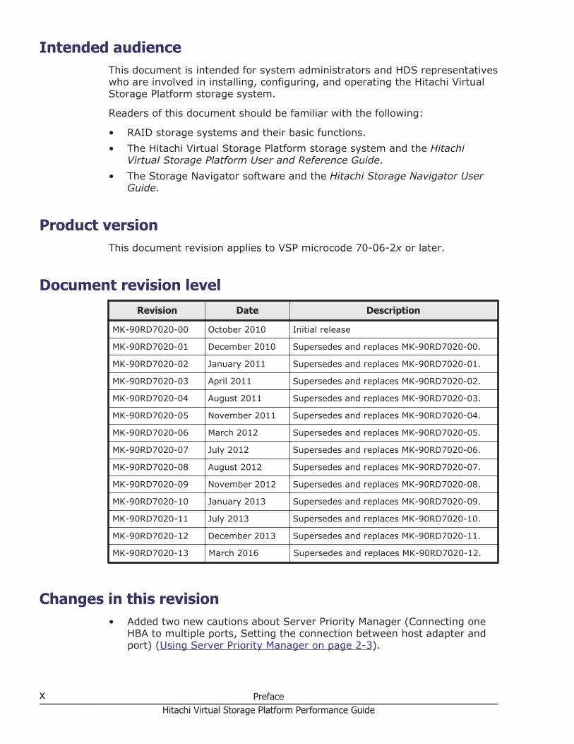
Document revision levelRevision Date Description
MK-90RD7020-00 October 2010 Initial release
MK-90RD7020-01 December 2010 Supersedes and replaces MK-90RD7020-00.
MK-90RD7020-02 January 2011 Supersedes and replaces MK-90RD7020-01.
MK-90RD7020-03 April 2011 Supersedes and replaces MK-90RD7020-02.
MK-90RD7020-04 August 2011 Supersedes and replaces MK-90RD7020-03.
MK-90RD7020-05 November 2011 Supersedes and replaces MK-90RD7020-04.
MK-90RD7020-06 March 2012 Supersedes and replaces MK-90RD7020-05.
MK-90RD7020-07 July 2012 Supersedes and replaces MK-90RD7020-06.
MK-90RD7020-08 August 2012 Supersedes and replaces MK-90RD7020-07.
MK-90RD7020-09 November 2012 Supersedes and replaces MK-90RD7020-08.
MK-90RD7020-10 January 2013 Supersedes and replaces MK-90RD7020-09.
MK-90RD7020-11 July 2013 Supersedes and replaces MK-90RD7020-10.
MK-90RD7020-12 December 2013 Supersedes and replaces MK-90RD7020-11.
MK-90RD7020-13 March 2016 Supersedes and replaces MK-90RD7020-12.
Changes in this revision• Added two new cautions about Server Priority Manager (Connecting one
HBA to multiple ports, Setting the connection between host adapter andport) (Using Server Priority Manager on page 2-3).
x PrefaceHitachi Virtual Storage Platform Performance Guide
Referenced documentsVirtual Storage Platform documentation:
• Hitachi Copy-on-Write Snapshot User Guide, MK-90RD7013• Provisioning Guide for Mainframe Systems, MK-90RD7021• Provisioning Guide for Open Systems, MK-90RD7022• Hitachi ShadowImage® for Mainframe User Guide, MK-90RD7023• Hitachi ShadowImage® User Guide, MK-90RD7024• Hitachi Storage Navigator User Guide, MK-90RD7027• Hitachi Storage Navigator Messages, MK-90RD7028• Hitachi TrueCopy® for Mainframe User Guide, MK-90RD7029• Hitachi TrueCopy® User Guide, MK-90RD7030• Hitachi Universal Replicator for Mainframe User Guide, MK-90RD7031• Hitachi Universal Replicator User Guide, MK-90RD7032• Hitachi Universal Volume Manager User Guide, MK-90RD7033• Hitachi Virtual Storage Platform User and Reference Guide, MK-90RD7042
Document organizationThe following table provides an overview of the contents and organization ofthis document. Click the chapter title in the left column to go to that chapter.The first page of each chapter provides links to the sections in that chapter.
Chapter Description
Chapter 1, Performanceoverview on page 1-1
Provides an overview of performance monitoring andmanagement of the Virtual Storage Platform storagesystem.
Chapter 2, Interoperability ofPerformance Monitor and otherproducts on page 2-1
Describes the interoperability considerations forPerformance Monitor.
Chapter 3, Monitoring WWNs onpage 3-1
Provides instructions for monitoring control units (CUs)using Hitachi Performance Monitor.
Chapter 4, Monitoring CUs onpage 4-1
Provides instructions for monitoring WWNs usingHitachi Performance Monitor.
Chapter 5, Monitoring operationon page 5-1
Provides instructions for monitoring operations usingHitachi Performance Monitor.
Chapter 6, Setting statisticalstorage ranges on page 6-1
Provides instructions for setting statistical storageranges using Hitachi Performance Monitor.
Chapter 7, Working with graphson page 7-1
Provides instructions for working with graphs ofperformance data.
Chapter 8, Changing display ofgraphs on page 8-1
Provides instructions for changing display of graphs ofperformance data.
Preface xiHitachi Virtual Storage Platform Performance Guide
Chapter Description
Chapter 9, Server PriorityManager operations on page9-1
Provides instructions for operating the Server PriorityManager software.
Chapter 10, Creating virtualcache partitions on page 10-1
Provides instructions for creating virtual cachepartitions using Hitachi Virtual Partition Manager.
Chapter 11, Estimating cachesize on page 11-1
Provides instructions for estimating cache size usingHitachi Cache Residency Manager.
Chapter 12, Managing residentcache on page 12-1
Provides instructions for performing Cache ResidencyManager operations.
Chapter 13, Troubleshooting onpage 13-1
Provides troubleshooting information for PerformanceMonitor, Virtual Partition Manager and Cache ResidencyManager.
Appendix A, Export Tool onpage A-1
Provides instructions for using the Export Tool.
Appendix B, PerformanceMonitor GUI reference on pageB-1
Describes the Hitachi Storage Navigator windows anddialog boxes for Performance Monitor.
Appendix C, Server PriorityManager GUI reference on pageC-1
Describes the Hitachi Storage Navigator windows anddialog boxes for Server Priority Manager.
Appendix D, Virtual PartitionManager GUI reference on pageD-1
Describes the Hitachi Storage Navigator windows anddialog boxes for Virtual Partition Manager.
Appendix E, Cache ResidencyManager GUI reference on pageE-1
Describes the Hitachi Storage Navigator windows anddialog boxes for Cache Residency Manager.
Document conventionsThis document uses the following typographic conventions:
Convention Description
Bold Indicates text on a window or dialog box, including window anddialog box names, menus, menu options, buttons, fields, andlabels. Example: Click OK.
Italic Indicates a variable, which is a placeholder for actual textprovided by the user or system. Example: copy source-filetarget-fileNote: Angled brackets (< >) are also used to indicate variables.
screen/code Indicates text that is displayed on screen or entered by the user.Example: # pairdisplay -g oradb
< > angled brackets Indicates a variable, which is a placeholder for actual textprovided by the user or system. Example: # pairdisplay -g<group>
xii PrefaceHitachi Virtual Storage Platform Performance Guide
Convention Description
Note: Italic font is also used to indicate variables.
[ ] square brackets Indicates optional values. Example: [ a | b ] indicates that youcan choose a, b, or nothing.
{ } braces Indicates required or expected values. Example: { a | b }indicates that you must choose either a or b.
| vertical bar Indicates that you have a choice between two or more optionsor arguments. Examples:[ a | b ] indicates that you can choose a, b, or nothing.{ a | b } indicates that you must choose either a or b.
This document uses the following icons to draw attention to information:
Icon Meaning Description
Tip Provides helpful information, guidelines, or suggestions forperforming tasks more effectively.
Note Calls attention to important and/or additional information.
Caution Warns the user of adverse conditions and/or consequences(for example, disruptive operations).
WARNING Warns the user of severe conditions and/or consequences (forexample, destructive operations).
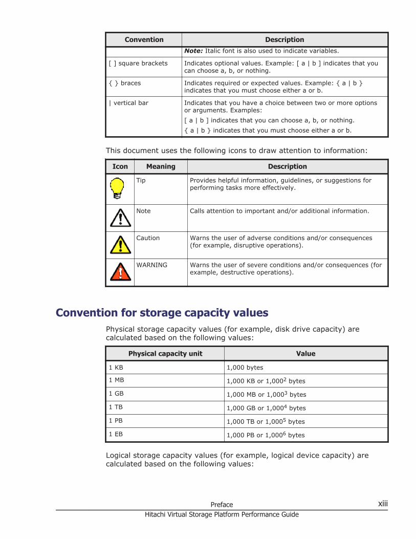
Convention for storage capacity valuesPhysical storage capacity values (for example, disk drive capacity) arecalculated based on the following values:
Physical capacity unit Value
1 KB 1,000 bytes
1 MB 1,000 KB or 1,0002 bytes
1 GB 1,000 MB or 1,0003 bytes
1 TB 1,000 GB or 1,0004 bytes
1 PB 1,000 TB or 1,0005 bytes
1 EB 1,000 PB or 1,0006 bytes
Logical storage capacity values (for example, logical device capacity) arecalculated based on the following values:
Preface xiiiHitachi Virtual Storage Platform Performance Guide
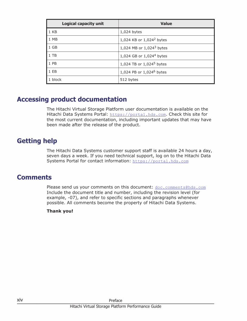
Logical capacity unit Value
1 KB 1,024 bytes
1 MB 1,024 KB or 1,0242 bytes
1 GB 1,024 MB or 1,0243 bytes
1 TB 1,024 GB or 1,0244 bytes
1 PB 1,024 TB or 1,0245 bytes
1 EB 1,024 PB or 1,0246 bytes
1 block 512 bytes
Accessing product documentationThe Hitachi Virtual Storage Platform user documentation is available on theHitachi Data Systems Portal: https://portal.hds.com. Check this site forthe most current documentation, including important updates that may havebeen made after the release of the product.
Getting helpThe Hitachi Data Systems customer support staff is available 24 hours a day,seven days a week. If you need technical support, log on to the Hitachi DataSystems Portal for contact information: https://portal.hds.com
CommentsPlease send us your comments on this document: [email protected] the document title and number, including the revision level (forexample, -07), and refer to specific sections and paragraphs wheneverpossible. All comments become the property of Hitachi Data Systems.
Thank you!
xiv PrefaceHitachi Virtual Storage Platform Performance Guide
1Performance overview
This chapter provides an overview of the Storage Navigator software productsthat enable you to monitor and manage the performance of the HitachiVirtual Storage Platform storage system.
□ Hitachi Performance Monitor overview
□ Server Priority Manager overview
□ Cache Residency Manager overview
□ Virtual Partition Manager overview
Performance overview 1-1Hitachi Virtual Storage Platform Performance Guide
Hitachi Performance Monitor overviewHitachi Performance Monitor enables you to monitor your Virtual StoragePlatform storage system and collect detailed usage and performancestatistics. You can view the storage system data on graphs to identifychanges in usage rates, workloads, and traffic, analyze trends in disk I/O,and detect peak I/O times. If there is a decrease in storage systemperformance (for example, delayed host response times), PerformanceMonitor can help you detect the cause of the problem and resolve it.
Performance Monitor provides data about storage system resources such asdrives, volumes, and microprocessors as well as statistics about front-end(host I/O) and back-end (disk I/O) workloads. Using the Performance Monitordata you can configure Server Priority Manager, Cache Residency Manager,and Virtual Partition Manager operations to manage and fine-tune theperformance of your storage system.
Note:
• To correctly display the performance statistics of a parity group, allvolumes belonging to the parity group must be specified as monitoringtargets.
• To correctly display the performance statistics of a LUSE volume, allvolumes making up the LUSE volume must be specified as monitoringtargets.
• The volumes to be monitored by Performance Monitor are specified bycontrol unit (CU). If the range of used CUs does not match the range ofCUs monitored by Performance Monitor, performance statistics may notbe collected for some volumes.
Server Priority Manager overviewServer Priority Manager allows you to designate prioritized ports (forexample, for production servers) and non-prioritized ports (for example, fordevelopment servers) and set upper limits and thresholds for the I/O activityof these ports to prevent low-priority activities from negatively impactinghigh-prority activities. Server Priority Manager operations can be performedonly for ports connected to open-systems hosts.
Performance of high-priority hostsIn a storage area network (SAN) environment, the storage system is usuallyconnected with many host servers. Some types of host servers often requirehigher performance than others. For example, production servers such asdatabase and application servers that are used to perform daily tasks ofbusiness organizations usually require high performance. If productionservers experience decreased performance, productivity in business activitiescan be negatively impacted. To prevent this from happening, the systemadministrator needs to maintain the performance of production servers at arelatively high level.
1-2 Performance overviewHitachi Virtual Storage Platform Performance Guide
Computer systems in business organizations often include developmentservers, which are used for developing, testing, and debugging businessapplications, as well as production servers. If development serversexperience decreased performance, development activities can be negativelyimpacted, but a drop in development server performance does not have asmuch negative impact to the entire organization as a drop in productionserver performance. In this case, you can use Server Priority Manager to givehigher priority to I/O activity from production servers than I/O activity fromdevelopment servers to manage and control the impact of developmentactivities.
Upper-limit controlUsing Server Priority Manager you can limit the number of I/O requests fromservers to the storage system as well as the amount of data that can betransferred between the servers and the storage system to maintainproduction server performance at the required levels. This practice of limitingthe performance of low-priority host servers is called upper-limit control.
Threshold controlWhile upper-limit control can help production servers to perform at higherlevels during periods of heavy use, it may not be useful when productionservers are not busy. For example, if the I/O activity from production serversis high between 09:00 and 15:00 hours and decreases significantly after15:00, upper-limit control for development servers may not be required after15:00.
To address this situation Server Priority Manager provides threshold control,which automatically disables upper-limit control when I/O traffic betweenproduction servers and the storage system decreases to a user-specifiedlevel. This user-specified level at which upper-limit control is disabled is calledthe threshold. You can specify the threshold as an I/O rate (number of I/Osper second) and a data transfer rate (amount of data transferred persecond).
For example, if you set a threshold of 500 I/Os per second to the storagesystem, the upper-limit controls for development servers are disabled whenthe I/O rate of the production servers drops below 500 I/Os per second. Ifthe I/O rate of the production servers goes up and exceeds 500 I/Os persecond, upper-limit control is restored to the development servers.
If you also set a threshold of 20 MB per second to the storage system, thedata transfer rate limit for the development servers is not reached when theamount of data transferred between the storage system and the productionservers is less than 20 MB per second.
Cache Residency Manager overviewCache Residency Manager enables you to store frequently accessed data inthe storage system's cache memory so that it is immediately available to
Performance overview 1-3Hitachi Virtual Storage Platform Performance Guide
hosts. Using Cache Residency Manager you can increase the data accessspeed for specific data by enabling read and write I/Os to be performed atthe higher front-end access speeds. You can use Cache Residency Managerfor both open-systems and mainframe data.
When Cache Residency Manager is used, total storage system cache capacitymust be increased to avoid data access performance degradation for non-cache-resident data. The maximum allowable Cache Residency Managercache area is configured when the cache is installed, so you must plancarefully for Cache Residency Manager operations and work with your HitachiData Systems representative to calculate the required amount of cachememory for your configuration and requirements.
Cache Residency Manager provides the following functions:
• Prestaging data in cache• Priority cache mode• Bind cache mode
Once data has been placed in cache, the cache mode cannot be changedwithout cache extension. If you need to change the cache mode withoutcache extension, you must release the data from cache, and then place thedata back in cache with the desired mode.
Prestaging data in cacheUsing Cache Residency Manager you can place specific data into user-definedCache Residency Manager cache areas, also called cache extents, before it isaccessed by the host. This is called prestaging data in cache. Whenprestaging is used, the host locates the prestaged data in the CacheResidency Manager cache during the first access, thereby improving dataaccess performance. Prestaging can be used for both priority mode and bindmode operations.
Prestaging occurs under any of the following circumstances:
• When prestaging is performed using Cache Residency Manager.• When the storage system is powered on.• When cache maintenance is performed.
1-4 Performance overviewHitachi Virtual Storage Platform Performance Guide
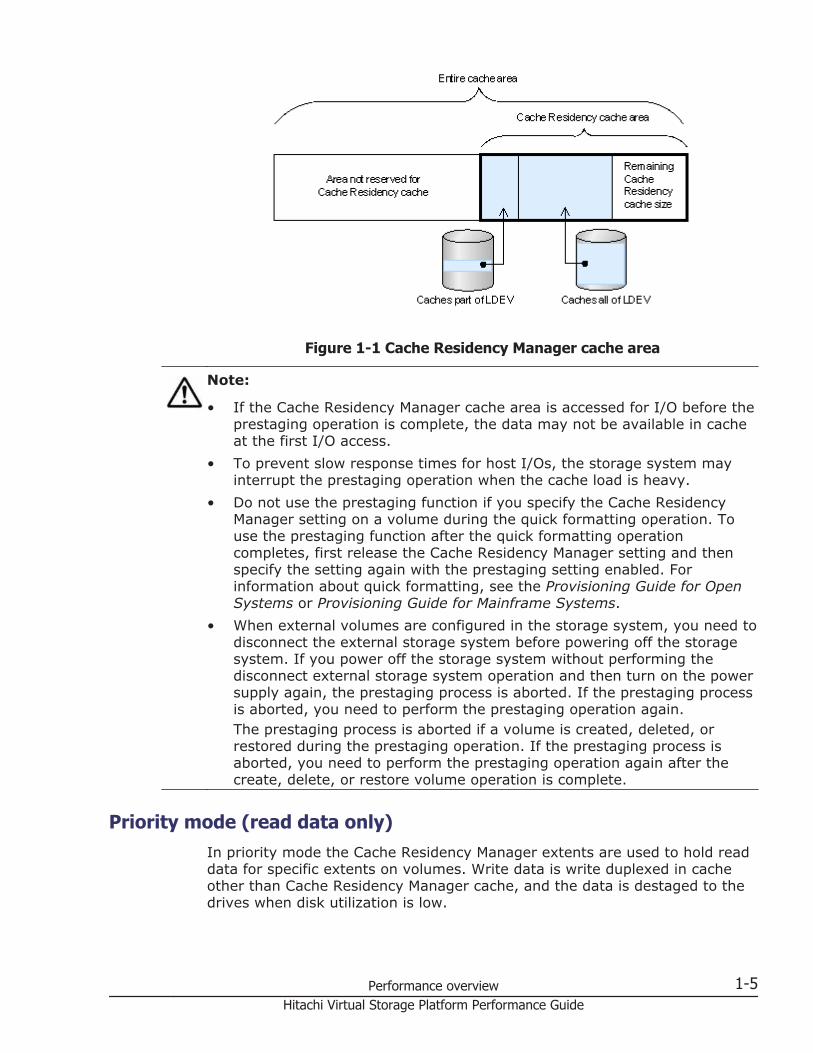
Figure 1-1 Cache Residency Manager cache area
Note:
• If the Cache Residency Manager cache area is accessed for I/O before theprestaging operation is complete, the data may not be available in cacheat the first I/O access.
• To prevent slow response times for host I/Os, the storage system mayinterrupt the prestaging operation when the cache load is heavy.
• Do not use the prestaging function if you specify the Cache ResidencyManager setting on a volume during the quick formatting operation. Touse the prestaging function after the quick formatting operationcompletes, first release the Cache Residency Manager setting and thenspecify the setting again with the prestaging setting enabled. Forinformation about quick formatting, see the Provisioning Guide for OpenSystems or Provisioning Guide for Mainframe Systems.
• When external volumes are configured in the storage system, you need todisconnect the external storage system before powering off the storagesystem. If you power off the storage system without performing thedisconnect external storage system operation and then turn on the powersupply again, the prestaging process is aborted. If the prestaging processis aborted, you need to perform the prestaging operation again.The prestaging process is aborted if a volume is created, deleted, orrestored during the prestaging operation. If the prestaging process isaborted, you need to perform the prestaging operation again after thecreate, delete, or restore volume operation is complete.
Priority mode (read data only)In priority mode the Cache Residency Manager extents are used to hold readdata for specific extents on volumes. Write data is write duplexed in cacheother than Cache Residency Manager cache, and the data is destaged to thedrives when disk utilization is low.
Performance overview 1-5Hitachi Virtual Storage Platform Performance Guide
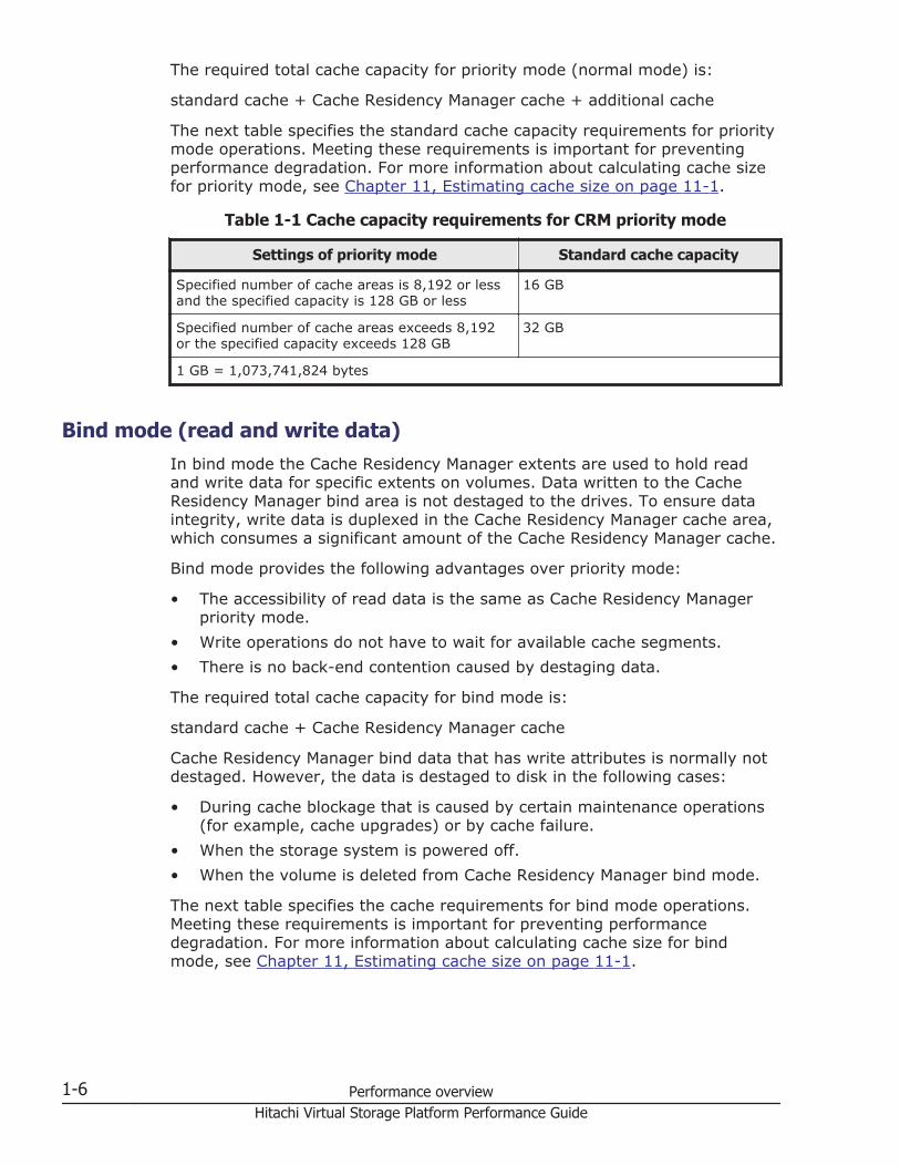
The required total cache capacity for priority mode (normal mode) is:
standard cache + Cache Residency Manager cache + additional cache
The next table specifies the standard cache capacity requirements for prioritymode operations. Meeting these requirements is important for preventingperformance degradation. For more information about calculating cache sizefor priority mode, see Chapter 11, Estimating cache size on page 11-1.
Table 1-1 Cache capacity requirements for CRM priority mode
Settings of priority mode Standard cache capacity
Specified number of cache areas is 8,192 or lessand the specified capacity is 128 GB or less
16 GB
Specified number of cache areas exceeds 8,192or the specified capacity exceeds 128 GB
32 GB
1 GB = 1,073,741,824 bytes
Bind mode (read and write data)In bind mode the Cache Residency Manager extents are used to hold readand write data for specific extents on volumes. Data written to the CacheResidency Manager bind area is not destaged to the drives. To ensure dataintegrity, write data is duplexed in the Cache Residency Manager cache area,which consumes a significant amount of the Cache Residency Manager cache.
Bind mode provides the following advantages over priority mode:
• The accessibility of read data is the same as Cache Residency Managerpriority mode.
• Write operations do not have to wait for available cache segments.• There is no back-end contention caused by destaging data.
The required total cache capacity for bind mode is:
standard cache + Cache Residency Manager cache
Cache Residency Manager bind data that has write attributes is normally notdestaged. However, the data is destaged to disk in the following cases:
• During cache blockage that is caused by certain maintenance operations(for example, cache upgrades) or by cache failure.
• When the storage system is powered off.• When the volume is deleted from Cache Residency Manager bind mode.
The next table specifies the cache requirements for bind mode operations.Meeting these requirements is important for preventing performancedegradation. For more information about calculating cache size for bindmode, see Chapter 11, Estimating cache size on page 11-1.
1-6 Performance overviewHitachi Virtual Storage Platform Performance Guide
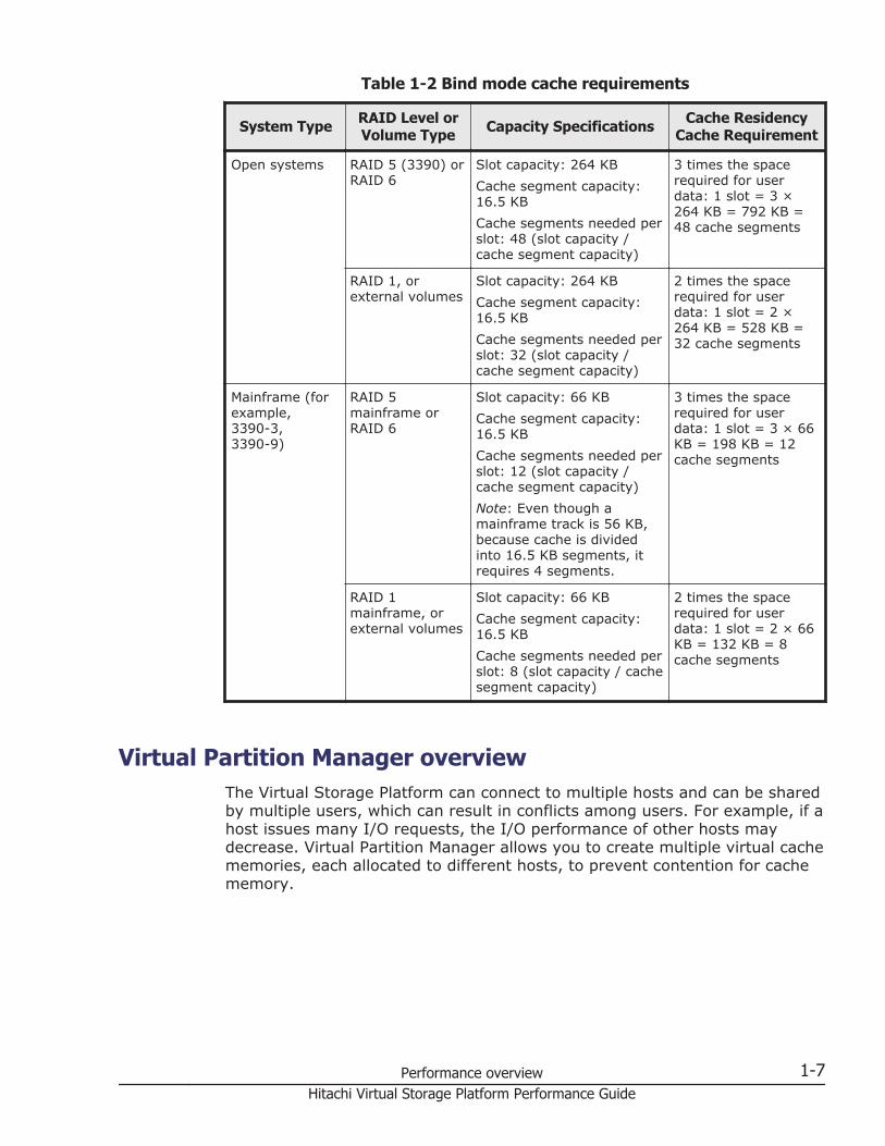
Table 1-2 Bind mode cache requirements
System Type RAID Level orVolume Type Capacity Specifications Cache Residency
Cache Requirement
Open systems RAID 5 (3390) orRAID 6
Slot capacity: 264 KBCache segment capacity:16.5 KBCache segments needed perslot: 48 (slot capacity /cache segment capacity)
3 times the spacerequired for userdata: 1 slot = 3 ×264 KB = 792 KB =48 cache segments
RAID 1, orexternal volumes
Slot capacity: 264 KBCache segment capacity:16.5 KBCache segments needed perslot: 32 (slot capacity /cache segment capacity)
2 times the spacerequired for userdata: 1 slot = 2 ×264 KB = 528 KB =32 cache segments
Mainframe (forexample,3390-3,3390-9)
RAID 5mainframe orRAID 6
Slot capacity: 66 KBCache segment capacity:16.5 KBCache segments needed perslot: 12 (slot capacity /cache segment capacity)Note: Even though amainframe track is 56 KB,because cache is dividedinto 16.5 KB segments, itrequires 4 segments.
3 times the spacerequired for userdata: 1 slot = 3 × 66KB = 198 KB = 12cache segments
RAID 1mainframe, orexternal volumes
Slot capacity: 66 KBCache segment capacity:16.5 KBCache segments needed perslot: 8 (slot capacity / cachesegment capacity)
2 times the spacerequired for userdata: 1 slot = 2 × 66KB = 132 KB = 8cache segments
Virtual Partition Manager overviewThe Virtual Storage Platform can connect to multiple hosts and can be sharedby multiple users, which can result in conflicts among users. For example, if ahost issues many I/O requests, the I/O performance of other hosts maydecrease. Virtual Partition Manager allows you to create multiple virtual cachememories, each allocated to different hosts, to prevent contention for cachememory.
Performance overview 1-7Hitachi Virtual Storage Platform Performance Guide

1-8 Performance overviewHitachi Virtual Storage Platform Performance Guide
2Interoperability of Performance Monitor
and other products
This chapter describes the interoperability of Performance Monitor and otherproducts.
□ Cautions and restrictions for monitoring
□ Cautions and restrictions for usage statistics
□ Using Server Priority Manager
Interoperability of Performance Monitor and other products 2-1Hitachi Virtual Storage Platform Performance Guide
Cautions and restrictions for monitoringPerformance monitoring has the following cautions and restrictions:
• Storage system maintenanceIf the storage system is undergoing the following maintenance operationsduring monitoring, the monitoring data might contain extremely largevalues.
¢ Adding, replacing, or removing cache memory.¢ Adding, replacing, or removing data drives.¢ Changing the storage system configuration.¢ Replacing the microprogram.¢ Formatting or quick formatting logical devices¢ Adding on, replacing, or removing MP blades
• Storage system power-offIf the storage system is powered off during monitoring, monitoring stopswhile the storage system is powered off. When the storage system ispowered up again, monitoring continues. However, Performance Monitorcannot display information about the period while the storage system ispowered off. Therefore, the monitoring data immediately after poweringon again might contain extremely large values.
• Microprogram replacementAfter the microprogram is replaced, monitoring data is not stored until theservice engineer releases the SVP from Modify mode. While the SVP is inModify mode, inaccurate data is displayed.
• Changing the SVP time settingIf the SVP time setting is changed while the monitoring switch is enabled,the following monitoring errors can occur:
¢ Invalid monitoring data appears.¢ No monitoring data is collected.To change the SVP time setting, first disable the monitoring switch,change the SVP time setting, and then re-enable the monitoring switch.After that, obtain the monitoring data. For details about the monitoringswitch, see Starting monitoring on page 5-2.
• WWN monitoringYou must configure some settings before the traffic between host busadapters and storage system ports can be monitored. For details, seeAdding new WWNs to monitor on page 3-2, Adding WWNs to ports onpage 3-3, and Connecting WWNs to ports on page 3-4.
Cautions and restrictions for usage statistics• Usage statistics for the last three months (93 days) are displayed in long-
range monitoring, and usage statistics for up to the last 15 days are
2-2 Interoperability of Performance Monitor and other productsHitachi Virtual Storage Platform Performance Guide
displayed in short-range monitoring. Usage statistics outside of theseranges are deleted from the storage system.
• In the short range, monitoring results are retained for the last 8 hours to15 days depending on the specified gathering interval. If the retentionperiod has passed since a monitoring result was obtained, the previousresult has been deleted from the storage system and cannot be displayed.
• When the monitoring switch is set to disabled, no monitoring data iscollected. This applies to both long-range and short-range data.
• For short-range monitoring, if the host I/O workload is high, the storagesystem gives higher priority to I/O processing than to monitoring. If thisoccurs, some monitoring data might be missing. If monitoring data ismissing frequently, use the Edit Time Range option to lengthen thecollection interval. For details, see Starting monitoring on page 5-2.
• The monitoring data (short-range and long-range) may have a margin oferror.
• If the SVP is overloaded, the system might require more time than thegathering interval allows to update the display of monitoring data. If thisoccurs, some portion of monitoring data is not displayed. For example,suppose that the gathering interval is 1 minute. In this case, if the displayin the Performance Management window is updated at 9:00 and the nextupdate occurs at 9:02, the window (including the graph) does not displaythe monitoring result for the period of 9:00 to 9:01. This situation canoccur when the following maintenance operations are performed:
¢ Adding, replacing, or removing cache memory.¢ Adding, replacing, or removing data drives.¢ Changing the storage system configuration.¢ Replacing the microprogram.
• Pool-VOLs of Thin Image, Copy-on-Write Snapshot, Dynamic Provisioning,and Dynamic Provisioning for Mainframe are not monitored.
Note: When you run the CCI horctakeover or pairresync-swaps command fora UR pair or the BCM YKRESYNC REVERSE command for a URz pair, theprimary and secondary volumes are swapped. You can collect the before-swapped information immediately after you run any of the commands.Incorrect monitoring data will be generated for a short time but will becorrected automatically when the monitoring data gets updated. The incorrectdata will also be generated when the volume used for a secondary volume isused as a primary volume after a UR or URz pair is deleted.
Using Server Priority Manager• Starting Server Priority Manager: Ensure that the Time Range in the
Monitor Performance window is not set to Use Real Time. You cannotstart Server Priority Manager in real-time mode.
• I/O rates and transfer rates: Server Priority Manager runs based onI/O rates and transfer rates measured by Performance Monitor.Performance Monitor measures I/O rates and transfer rates every second,
Interoperability of Performance Monitor and other products 2-3Hitachi Virtual Storage Platform Performance Guide
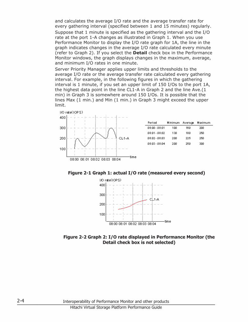
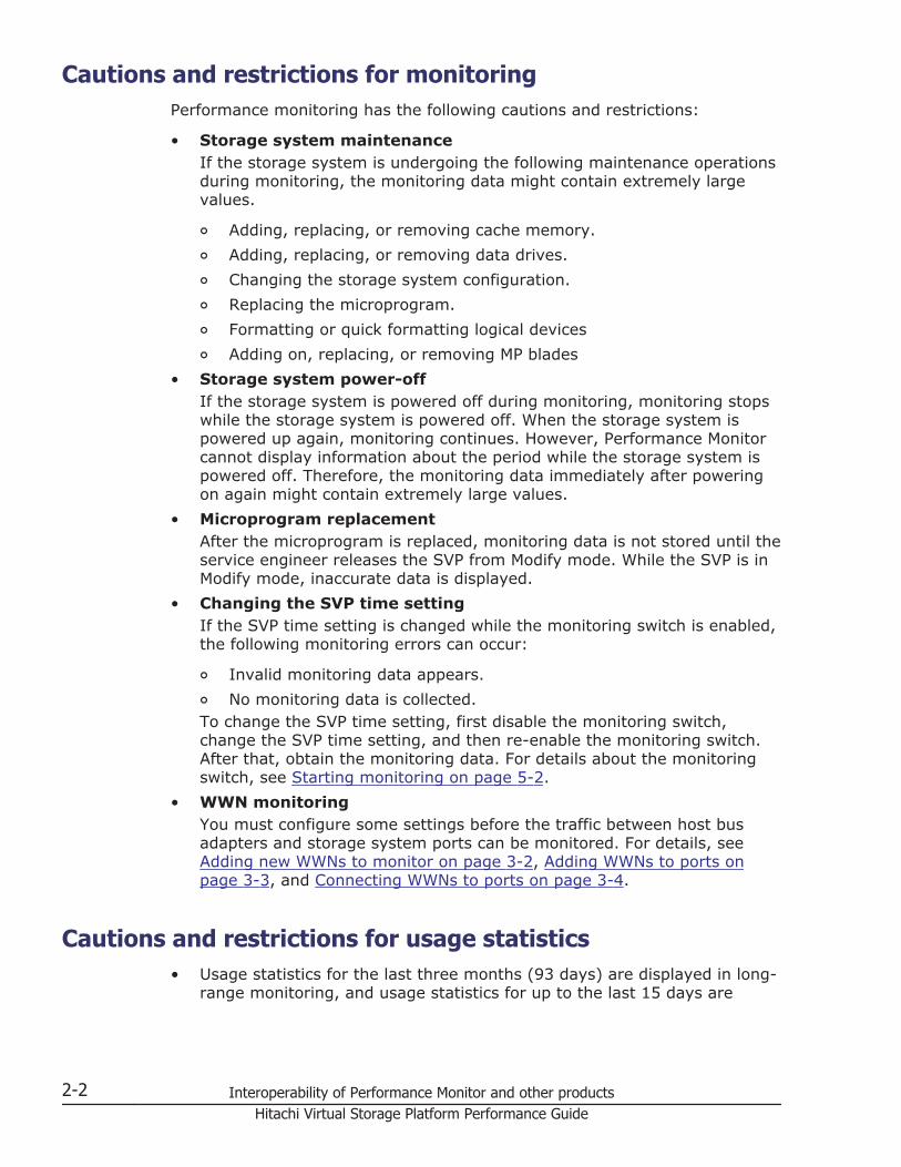
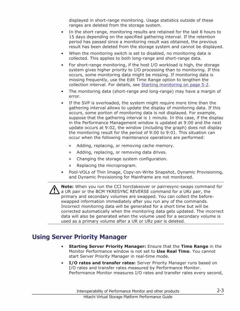
and calculates the average I/O rate and the average transfer rate forevery gathering interval (specified between 1 and 15 minutes) regularly.Suppose that 1 minute is specified as the gathering interval and the I/Orate at the port 1-A changes as illustrated in Graph 1. When you usePerformance Monitor to display the I/O rate graph for 1A, the line in thegraph indicates changes in the average I/O rate calculated every minute(refer to Graph 2). If you select the Detail check box in the PerformanceMonitor windows, the graph displays changes in the maximum, average,and minimum I/O rates in one minute.Server Priority Manager applies upper limits and thresholds to theaverage I/O rate or the average transfer rate calculated every gatheringinterval. For example, in the following figures in which the gatheringinterval is 1 minute, if you set an upper limit of 150 I/Os to the port 1A,the highest data point in the line CL1-A in Graph 2 and the line Ave.(1min) in Graph 3 is somewhere around 150 I/Os. It is possible that thelines Max (1 min.) and Min (1 min.) in Graph 3 might exceed the upperlimit.
Figure 2-1 Graph 1: actual I/O rate (measured every second)
Figure 2-2 Graph 2: I/O rate displayed in Performance Monitor (theDetail check box is not selected)
2-4 Interoperability of Performance Monitor and other productsHitachi Virtual Storage Platform Performance Guide
Figure 2-3 Graph 3: I/O rate displayed in Performance Monitor (theDetail check box is selected)
• Remote copy functions: When the remote copy functions (TrueCopy,TrueCopy for Mainframe, Universal Replicator, and Universal Replicatorfor Mainframe) are used in your environment, Server Priority Managermonitors write I/O requests issued from initiator ports of your storagesystem.If you give a priority attribute to the RCU target port, all I/Os received onthe port will be controlled as the threshold control and its performancedata will be added to the total number of I/Os (or the transfer rate) of allprioritized ports. I/Os on the port will not be limited.If you give a non priority attribute to the RCU target port, I/O requestsfrom the initiator port will not be controlled as threshold control and I/Oson the port will not be limited. On the other hand, I/O requests from ahost will be controlled as the upper limit control and I/Os on the port willbe limited.
• Statistics of Initiator/External ports: The initiator ports and externalports of your storage system are not controlled by Server PriorityManager. Although you can set Prioritize or Non-Prioritize to initiator portsand external ports by using Server Priority Manager, the initiator portsand the external ports become the prioritized ports that are not underthreshold control, regardless of whether the setting of the ports arePrioritize or Non-Prioritize. If the port attributes are changed fromInitiator/External into Target/RCU Target, the settings by Server PriorityManager take effect instantly and the ports are subject to threshold orupper limit control.The statistics of the Monitor Performance window are sum total ofstatistics on Target/RCU Target ports that are controlled by Server PriorityManager. The statistics does not include the statistics of Initiator/Externalports. Because the statistics of Initiator/External ports and Target/RCUTarget ports are based on different calculation methods, it is impossible tosum up the statistics of Initiator/External ports and Target/RCU Targetports.
• Settings of Server Priority Manager main window: The ServerPriority Manager main window has two tabs: the Port tab and the WWNtab. The settings on only one tab at a time can be applied to the storagesystem. If you make settings on both tabs, the settings cannot be appliedat the same time. When you select Apply, the settings on the last tab on
Interoperability of Performance Monitor and other products 2-5Hitachi Virtual Storage Platform Performance Guide
which you made settings are applied, and the settings on the other tabare discarded.
• Settings for Server Priority Manager from Command ControlInterface: You cannot operate Server Priority Manager from CCI andHitachi Storage Navigator simultaneously. If you change some settings forServer Priority Manager from CCI, you cannot change those settings fromHitachi Storage Navigator. If you do, some settings might not appear.Before you change features that use Server Priority Manager, delete allServer Priority Manager settings from the currently used features.
• Connecting one HBA to multiple ports: If one host adapter isconnected to multiple ports and you specify an upper limit of the non-prioritized WWN for one port, the specified upper limit value will beapplied to the host adapter settings for other connected portsautomatically.
• Setting the connection between host adapter and port: To makesetting for connecting the host adapter's WWN and the port, use theWWN tab of the Server Priority Manager main window. Alternatively youcan use the Monitored WWNs tab of the Performance Monitor mainwindow. Note that the monitored WWN name displayed in PerformanceMonitor is displayed as the SPM name in Server Priority Manager.
2-6 Interoperability of Performance Monitor and other productsHitachi Virtual Storage Platform Performance Guide

3Monitoring WWNs
This topic describes how to set up WWNs to be monitored.
□ Viewing the WWNs that are being monitored
□ Adding new WWNs to monitor
□ Removing WWNs to monitor
□ Adding WWNs to ports
□ Editing the WWN nickname
□ Connecting WWNs to ports
□ Deleting unused WWNs from monitoring targets
Monitoring WWNs 3-1Hitachi Virtual Storage Platform Performance Guide
Viewing the WWNs that are being monitoredTo view the WWNs that are being monitored:
1. Display the Storage Navigator main window.2. Select Performance Monitor in Explorer, and select Performance
Monitor in the tree.The Performance Monitor window opens.
3. Select the Monitored WWNs tab to see the list of WWNs that arecurrently being monitored.
Adding new WWNs to monitorTo add new WWNs to monitor:
1. Display the Storage Navigator main window.2. Select Performance Monitor in Explorer, and select Performance
Monitor in the tree.The Performance Monitor window opens.
3. Select the Monitored WWNs tab.4. Click Edit WWN Monitor Mode.
The Edit WWN Monitor Mode window opens.5. Select the WWNs in the Unmonitored WWNs list, and click Add.6. Click Finish to display the Confirm window.7. Click Apply in the Confirm window to apply the settings to the storage
system.
Removing WWNs to monitorTo remove WWNs to monitor:
1. Display the Storage Navigator main window.2. Select Performance Monitor in Explorer, and select Performance
Monitor in the tree.The Performance Monitor window opens.
3. Click the Monitored WWNs tab.4. Click Edit WWN Monitor Mode.
The Edit WWN Monitor Mode window opens.5. Select the WWNs in the Monitored WWNs list that you want to remove,
and click Remove.6. Click Finish to display the Confirm window.7. Click Apply in the Confirm window.8. When the warning message appears, click OK to close the message. The
settings are applied to the storage system.
3-2 Monitoring WWNsHitachi Virtual Storage Platform Performance Guide
Adding WWNs to portsIf you want to monitor WWNs that are not connected to the storage system,you can add them to ports and set them up for monitoring with PerformanceMonitor.
1. Display the Storage Navigator main window.2. Select Performance Monitor in Explorer, and select Performance
Monitor in the tree.The Performance Monitor window opens.
3. Click the Monitored WWNs tab.4. Click Add New Monitored WWNs.
The Add New Monitored WWNs window opens.5. Specify the following information for each new WWN:
¢ HBA WWN (required)Enter the 16-digit hexadecimal number.
¢ WWN Name (optional)Enter the unique name to distinguish the host bus adapter fromothers. The WWN Name must be less than 64 characters and mustconsist of alphanumeric characters and at least one symbol.
¢ Port (In Available Ports)In the Available Ports list select the port connected to the WWN.Ports connected to mainframe hosts are not displayed, because theyare not supported for Performance Monitor.
6. Click Add. The added WWN is displayed in Selected WWNs.7. If you need to remove a WWN from the Selected WWNs list, select the
WWN and click Remove.8. When you are done adding new WWNs, click Finish.9. Click Apply in the Confirm window to apply the settings to the storage
system.
Editing the WWN nicknameTo edit the nickname of a WWN being monitored:
1. Display the Storage Navigator main window.2. Select Performance Monitor in Explorer, and select Performance
Monitor in the tree.The Performance Monitor window opens.
3. Click the Monitored WWNs tab to see the list of WWNs being monitored.4. Select the WWN to edit, and click Edit WWN. You can edit only one WWN
at a time. If you select multiple WWNs, an error will occur.The Edit WWN window opens.
5. Edit the HBA WWN and WWN Name fields as needed.
Monitoring WWNs 3-3Hitachi Virtual Storage Platform Performance Guide
¢ HBA WWNA 16-digit hexadecimal number. The value of HBA WWN must beunique in the storage system.
¢ WWN NameThe nickname distinguishes the host bus adapter from others. TheWWN Name must be less than 64 digits and must consist ofalphanumeric characters and at least one symbol.
6. Click Finish to display the Confirm window.7. Click Apply in the Confirm window to apply the settings to the storage
system.
Connecting WWNs to portsTo connect the WWNs to monitor to ports:
1. Display the Storage Navigator main window.2. Select Performance Monitor in Explorer, and select Performance
Monitor in the tree.The Performance Monitor window opens.
3. Click the Monitored WWNs tab.4. Select the WWN to connect to the port, and click Add to Ports.
The Add to Ports window opens. If you select a WWN to connect, selectone WWN in the list. If you select multiple WWNs and click Add to Ports,an error occurs.
5. Select a port to connect in Available Ports, and then click Add.However, the ports of the mainframe system are not displayed in the listbecause they are not supported for Performance Monitor.The added WWN and the port are specified for the Selected WWNs.
6. If necessary, select unnecessary row of a WWN and port in SelectedWWNs, and then click Remove.WWNs are deleted.
7. Click Finish to display the Confirm window.8. Click Apply in the Confirm window to apply the settings to the storage
system.
Deleting unused WWNs from monitoring targetsTo delete WWNs that are being monitored:
1. Display the Storage Navigator main window.2. Select Performance Monitor in Explorer, and select Performance
Monitor in the tree.The Performance Monitor window opens.
3. Click the Monitored WWNs tab.4. Click Delete Unused WWNs to display the Confirm window.
3-4 Monitoring WWNsHitachi Virtual Storage Platform Performance Guide
5. Click Apply in the Confirm window.6. When the warning message appears, click OK to close the message. The
settings are applied to the storage system.
Monitoring WWNs 3-5Hitachi Virtual Storage Platform Performance Guide

3-6 Monitoring WWNsHitachi Virtual Storage Platform Performance Guide
4Monitoring CUs
This topic describes how to set up CUs to be monitored.
□ Displaying CUs to monitor
□ Adding and removing CUs to monitor
□ Confirming the status of CUs to monitor
Monitoring CUs 4-1Hitachi Virtual Storage Platform Performance Guide
Displaying CUs to monitorTo display the list of CUs to monitor:
1. Open the Storage Navigator main window.2. Select Performance Monitor in Explorer and select Performance Monitor
from the tree.3. Open the Monitored CUs tab. View the list of CUs.
Adding and removing CUs to monitor
Note: When a CU is removed from monitoring, the monitor data for that CUis deleted. If you want to save the data, export it first using the Export Tool(see Appendix A, Export Tool on page A-1), and then remove the CU.
1. Display the Storage Navigator main window.2. Select Performance Monitor in Explorer, and select Performance
Monitor in the tree.The Performance Monitor window opens.
3. Open the Monitored CUs tab.4. Click Edit CU Monitor Mode.
The Edit CU Monitor Mode window opens.5. To add CUs as monitoring target objects, select the CUs in the
Unmonitored CUs list, and click Add to move the selected CUs into theMonitored CUs list.To add all CUs in a parity group as monitoring target objects:
a. Click Select by Parity Groups in the Unmonitored CUs area.The Select by Parity Groups window opens. The available paritygroup IDs and number of CUs are displayed.
b. Select the parity group ID from the list and click Detail.The Parity Group Properties window opens. CUs and the number ofLDEVs are displayed.
c. Confirm the properties of the parity group and click Close.The Select by Parity Groups window opens.
d. Select the parity group to be the monitoring target in the Select byParity Groups window, and click OK.The CUs in the parity group are selected in the Unmonitored CUslist.
e. Click Add to move the selected CUs into the Monitored CUs list.6. To remove CUs as monitoring target objects, select the CUs in the
Monitored CUs list, and click Remove to move the selected CUs into theUnmonitored CUs list.
7. When you are done adding and/or deleting CUs, click Finish.8. When the confirmation dialog box opens, click Apply.
4-2 Monitoring CUsHitachi Virtual Storage Platform Performance Guide
If you are removing CUs, a warning message appears asking whether youwant to continue this operation even though monitor data will be deleted.
9. To add and remove the CUs, click OK. The new settings are registered inthe system.
Confirming the status of CUs to monitorTo view the monitoring status of CUs:
1. Display the Storage Navigator main window.2. Select Performance Monitor in Explorer, and select Performance
Monitor in the tree.The Performance Monitor window opens.
3. Open the Monitored CUs tab.4. Click Edit CU Monitor Mode.
The Edit CU Monitor Mode window opens.5. Click View CU Matrix in the Edit CU Monitor Mode window.
The View CU Matrix window opens. The following CUs are displayed inthe Monitored CUs window:
¢ Monitored CUs¢ Set monitored CUs¢ Release monitored CUs
6. Click Close.The Edit CU Monitor Mode window opens.
Monitoring CUs 4-3Hitachi Virtual Storage Platform Performance Guide

4-4 Monitoring CUsHitachi Virtual Storage Platform Performance Guide
5Monitoring operation
This topic describes how to start and stop the monitoring operation.
□ Performing monitoring operations
□ Starting monitoring
□ Stopping monitoring
Monitoring operation 5-1Hitachi Virtual Storage Platform Performance Guide
Performing monitoring operationsThis topic describes how to start or stop the monitoring operation.
• To start the monitoring operation, see Starting monitoring on page 5-2.• To stop the monitoring operation, see Stopping monitoring on page
5-2.
Starting monitoringTo start monitoring the storage system, start Performance Monitor and openthe Edit Monitoring Switch window. If this operation is performed, themonitoring result will be deleted.
1. Display the Storage Navigator main window.2. Select Performance Monitor in Explorer, and select Performance
Monitor in the tree.The Performance Monitor window opens.
3. Click Edit Monitoring Switch in the Performance Monitor window.The Edit Monitoring Switch window opens.
4. Click Enable in the Monitoring Switch field.5. Select the collecting interval in the Sample Interval.
Specify the interval to obtain usage statistics about the storage systemfor short range monitoring. This option is activated when you specifyEnable for Current Status. If CUs to be monitored are 64 or less, you canspecify the value between 1 and 15 minutes by minutes, and the defaultsetting is 1 minute. For example, if you specify 1 minute for the gatheringinterval, Performance Monitor collect statistics (for example, I/O rates andtransfer rates) every one minute.If CUs to be monitored are 65 or more, the gathering interval can bespecified to the value 5, 10 or 15 minutes (in the 5 minuted interval), anddefault is 5 minutes. For example, if you specify the gathering interval to5 minutes, Performance Monitor gathers statistics (for example, I/O rateand transfer rate) every 5 minutes.
6. Click Finish to display the Confirm window.7. Click Apply in the Confirm window.
A warning message appears, asking whether you continue this operationalthough graph data is deleted.
8. Click OK to start monitoring.When statistics are collected, a heavy workload is likely to be placed onservers. Therefore, the client processing might slow down.
Stopping monitoringTo stop monitoring the storage system:
1. Display the Storage Navigator main window.
5-2 Monitoring operationHitachi Virtual Storage Platform Performance Guide
2. Select Performance Monitor in Explorer, and select PerformanceMonitor in the tree.The Performance Monitor window opens.
3. Click Edit Monitoring Switch in the Performance Monitor window.The Edit Monitoring Switch window opens.
4. Click Disable in the Monitoring Switch field.The Sample Interval list is grayed out and becomes ineffective.
5. Click Finish to display the Confirm window.6. Click Apply in the Confirm window to stop monitoring.
Monitoring operation 5-3Hitachi Virtual Storage Platform Performance Guide

5-4 Monitoring operationHitachi Virtual Storage Platform Performance Guide
6Setting statistical storage ranges
This topic describes setting statistical storage ranges.
□ About statistical storage ranges
□ Setting the storing period of statistics
Setting statistical storage ranges 6-1Hitachi Virtual Storage Platform Performance Guide
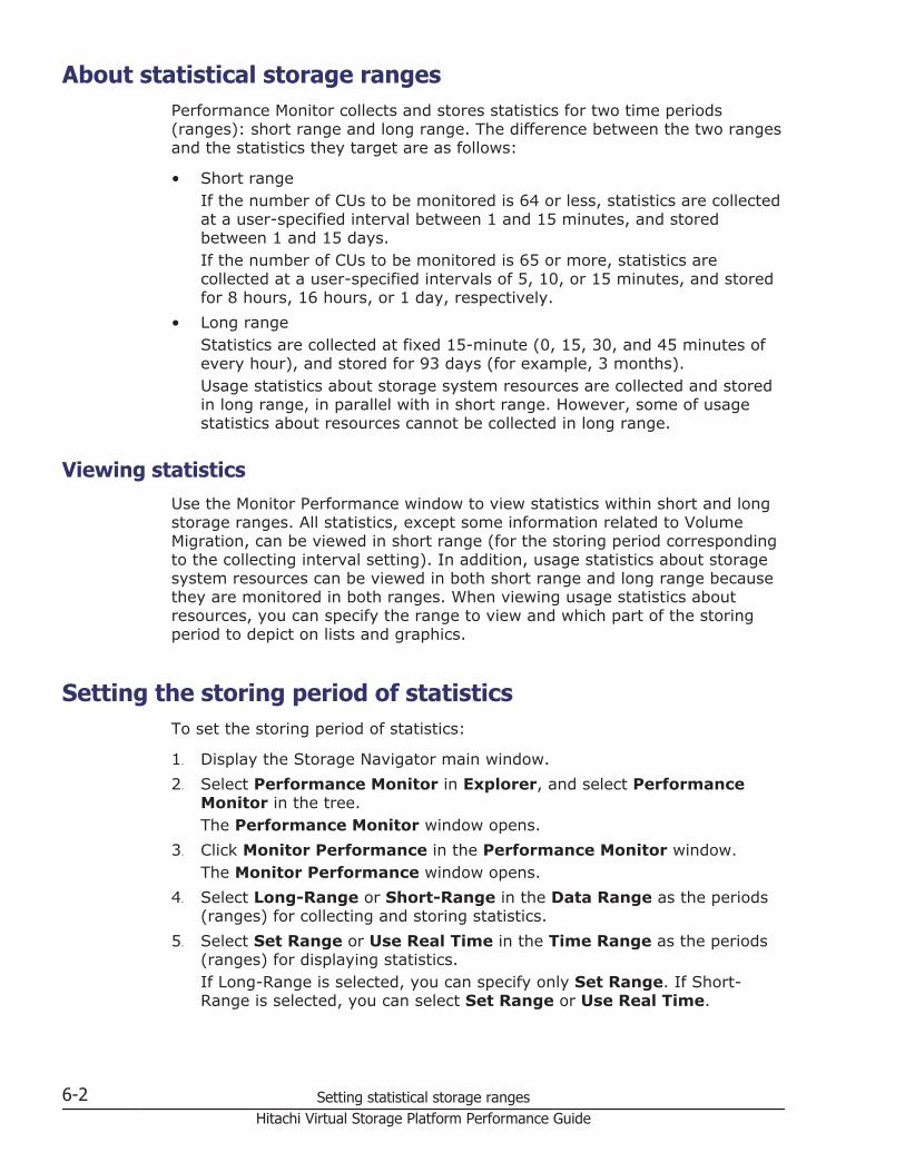
About statistical storage rangesPerformance Monitor collects and stores statistics for two time periods(ranges): short range and long range. The difference between the two rangesand the statistics they target are as follows:
• Short rangeIf the number of CUs to be monitored is 64 or less, statistics are collectedat a user-specified interval between 1 and 15 minutes, and storedbetween 1 and 15 days.If the number of CUs to be monitored is 65 or more, statistics arecollected at a user-specified intervals of 5, 10, or 15 minutes, and storedfor 8 hours, 16 hours, or 1 day, respectively.
• Long rangeStatistics are collected at fixed 15-minute (0, 15, 30, and 45 minutes ofevery hour), and stored for 93 days (for example, 3 months).Usage statistics about storage system resources are collected and storedin long range, in parallel with in short range. However, some of usagestatistics about resources cannot be collected in long range.
Viewing statisticsUse the Monitor Performance window to view statistics within short and longstorage ranges. All statistics, except some information related to VolumeMigration, can be viewed in short range (for the storing period correspondingto the collecting interval setting). In addition, usage statistics about storagesystem resources can be viewed in both short range and long range becausethey are monitored in both ranges. When viewing usage statistics aboutresources, you can specify the range to view and which part of the storingperiod to depict on lists and graphics.
Setting the storing period of statisticsTo set the storing period of statistics:
1. Display the Storage Navigator main window.2. Select Performance Monitor in Explorer, and select Performance
Monitor in the tree.The Performance Monitor window opens.
3. Click Monitor Performance in the Performance Monitor window.The Monitor Performance window opens.
4. Select Long-Range or Short-Range in the Data Range as the periods(ranges) for collecting and storing statistics.
5. Select Set Range or Use Real Time in the Time Range as the periods(ranges) for displaying statistics.If Long-Range is selected, you can specify only Set Range. If Short-Range is selected, you can select Set Range or Use Real Time.
6-2 Setting statistical storage rangesHitachi Virtual Storage Platform Performance Guide
Performance Monitor saves the statistics obtained up to 1440 times inSVP. Therefore, you can estimate the storing period of statistics with“gathering interval multiplied by 1440.” For example, if you specify oneminute for the gathering interval, the statistics for one day can be storedat the maximum from the following formula:1 minute x 1440 = 1440 minutes = 24 hours = 1 dayThis storing period is the range of display in the Monitor Performancewindows. When you specify one minute for the gathering interval like theexample above, Performance Monitor can display the statistics for oneday (for example, 24 hours) in the list and graph at the maximum. Also,when you specify 15 minutes for the gathering interval, PerformanceMonitor can display the statistics for 15 days in the list and graph at themaximum.
Setting statistical storage ranges 6-3Hitachi Virtual Storage Platform Performance Guide

6-4 Setting statistical storage rangesHitachi Virtual Storage Platform Performance Guide
7Working with graphs
This topic describes how to display statistical graphs.
□ Basic operation
□ Objects that can be displayed in graphs
□ Usage rates of MPs
□ Usage rate of a data recovery and reconstruction processor
□ Usage rate of cache memory
□ Write pending statistics
□ Access paths usage statistics
□ Throughput of storage system
□ Size of data transferred
□ Response times
□ Cache hit rates
□ Back-end performance
□ Hard disk drive usage statistics
□ Hard disk drive access rates
□ ShadowImage usage statistics
Working with graphs 7-1Hitachi Virtual Storage Platform Performance Guide
□ Detailed information of resources on top 20 usage rates
7-2 Working with graphsHitachi Virtual Storage Platform Performance Guide
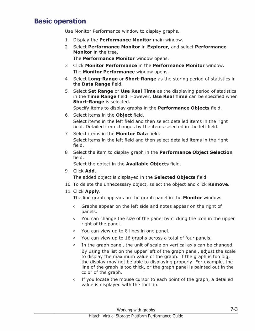
Basic operation Use Monitor Performance window to display graphs.
1. Display the Performance Monitor main window.2. Select Performance Monitor in Explorer, and select Performance
Monitor in the tree.The Performance Monitor window opens.
3. Click Monitor Performance in the Performance Monitor window.The Monitor Performance window opens.
4. Select Long-Range or Short-Range as the storing period of statistics inthe Data Range field.
5. Select Set Range or Use Real Time as the displaying period of statisticsin the Time Range field. However, Use Real Time can be specified whenShort-Range is selected.Specify items to display graphs in the Performance Objects field.
6. Select items in the Object field.Select items in the left field and then select detailed items in the rightfield. Detailed item changes by the items selected in the left field.
7. Select items in the Monitor Data field.Select items in the left field and then select detailed items in the rightfield.
8. Select the item to display graph in the Performance Object Selectionfield.Select the object in the Available Objects field.
9. Click Add.The added object is displayed in the Selected Objects field.
10. To delete the unnecessary object, select the object and click Remove.11. Click Apply.
The line graph appears on the graph panel in the Monitor window.
¢ Graphs appear on the left side and notes appear on the right ofpanels.
¢ You can change the size of the panel by clicking the icon in the upperright of the panel.
¢ You can view up to 8 lines in one panel.¢ You can view up to 16 graphs across a total of four panels.¢ In the graph panel, the unit of scale on vertical axis can be changed.
By using the list on the upper left of the graph panel, adjust the scaleto display the maximum value of the graph. If the graph is too big,the display may not be able to displaying properly. For example, theline of the graph is too thick, or the graph panel is painted out in thecolor of the graph.
¢ If you locate the mouse cursor to each point of the graph, a detailedvalue is displayed with the tool tip.
Working with graphs 7-3Hitachi Virtual Storage Platform Performance Guide
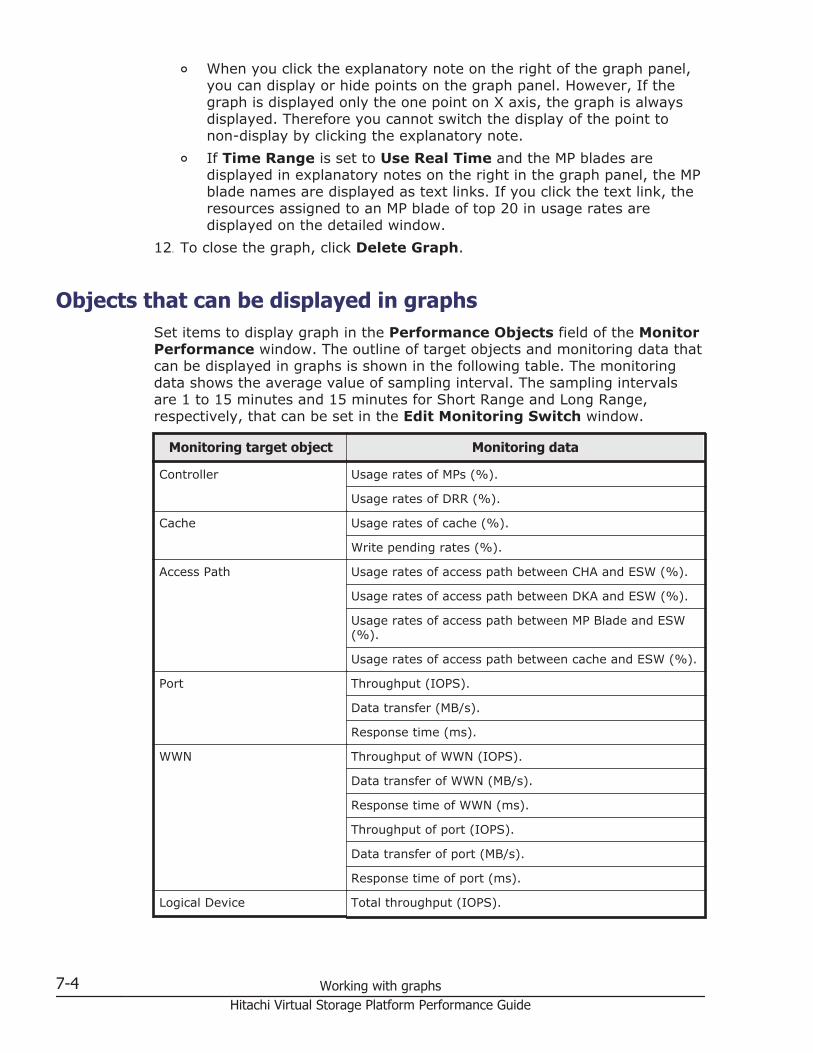
¢ When you click the explanatory note on the right of the graph panel,you can display or hide points on the graph panel. However, If thegraph is displayed only the one point on X axis, the graph is alwaysdisplayed. Therefore you cannot switch the display of the point tonon-display by clicking the explanatory note.
¢ If Time Range is set to Use Real Time and the MP blades aredisplayed in explanatory notes on the right in the graph panel, the MPblade names are displayed as text links. If you click the text link, theresources assigned to an MP blade of top 20 in usage rates aredisplayed on the detailed window.
12. To close the graph, click Delete Graph.
Objects that can be displayed in graphs Set items to display graph in the Performance Objects field of the MonitorPerformance window. The outline of target objects and monitoring data thatcan be displayed in graphs is shown in the following table. The monitoringdata shows the average value of sampling interval. The sampling intervalsare 1 to 15 minutes and 15 minutes for Short Range and Long Range,respectively, that can be set in the Edit Monitoring Switch window.
Monitoring target object Monitoring data
Controller Usage rates of MPs (%).
Usage rates of DRR (%).
Cache Usage rates of cache (%).
Write pending rates (%).
Access Path Usage rates of access path between CHA and ESW (%).
Usage rates of access path between DKA and ESW (%).
Usage rates of access path between MP Blade and ESW(%).
Usage rates of access path between cache and ESW (%).
Port Throughput (IOPS).
Data transfer (MB/s).
Response time (ms).
WWN Throughput of WWN (IOPS).
Data transfer of WWN (MB/s).
Response time of WWN (ms).
Throughput of port (IOPS).
Data transfer of port (MB/s).
Response time of port (ms).
Logical Device Total throughput (IOPS).
7-4 Working with graphsHitachi Virtual Storage Platform Performance Guide
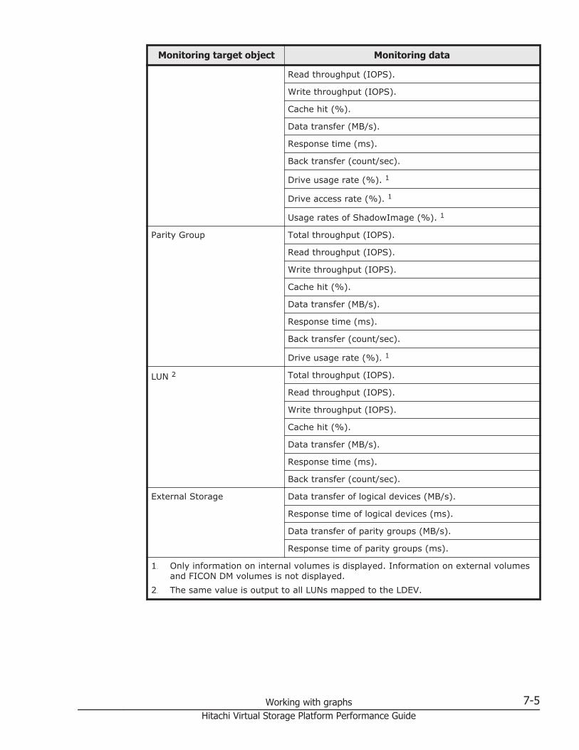
Monitoring target object Monitoring data
Read throughput (IOPS).
Write throughput (IOPS).
Cache hit (%).
Data transfer (MB/s).
Response time (ms).
Back transfer (count/sec).
Drive usage rate (%). 1
Drive access rate (%). 1
Usage rates of ShadowImage (%). 1
Parity Group Total throughput (IOPS).
Read throughput (IOPS).
Write throughput (IOPS).
Cache hit (%).
Data transfer (MB/s).
Response time (ms).
Back transfer (count/sec).
Drive usage rate (%). 1
LUN 2 Total throughput (IOPS).
Read throughput (IOPS).
Write throughput (IOPS).
Cache hit (%).
Data transfer (MB/s).
Response time (ms).
Back transfer (count/sec).
External Storage Data transfer of logical devices (MB/s).
Response time of logical devices (ms).
Data transfer of parity groups (MB/s).
Response time of parity groups (ms).
1. Only information on internal volumes is displayed. Information on external volumesand FICON DM volumes is not displayed.
2. The same value is output to all LUNs mapped to the LDEV.
Working with graphs 7-5Hitachi Virtual Storage Platform Performance Guide
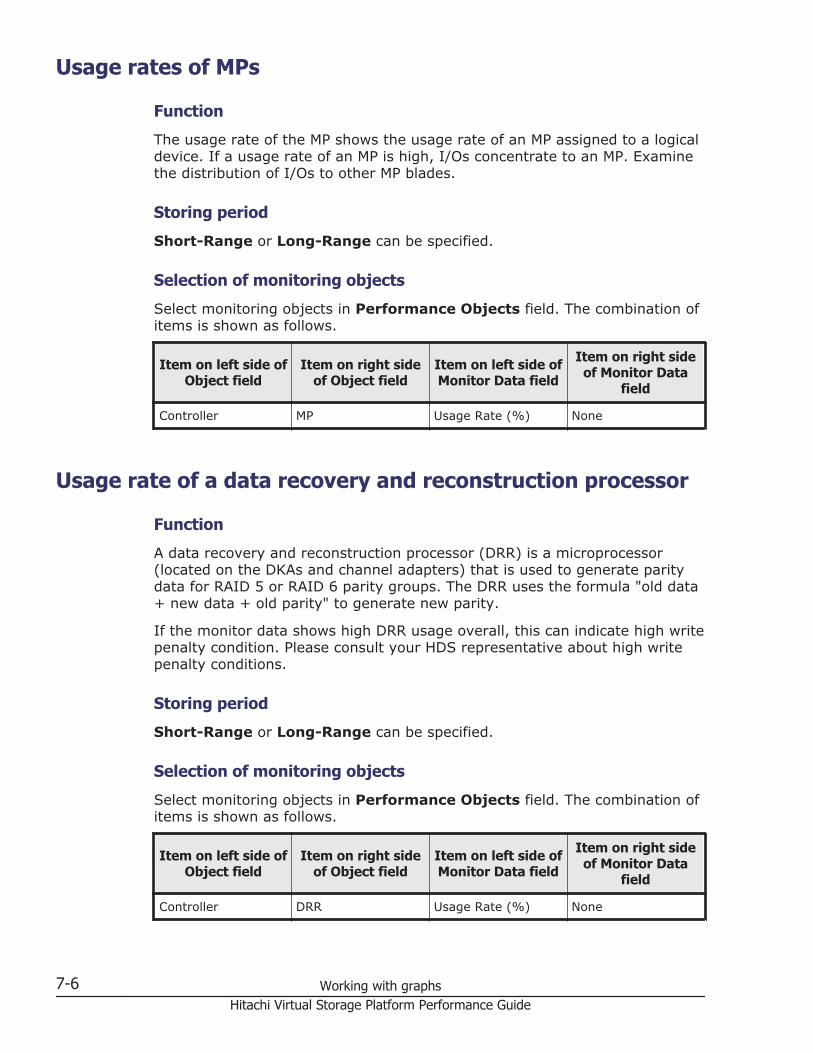
Usage rates of MPs
Function
The usage rate of the MP shows the usage rate of an MP assigned to a logicaldevice. If a usage rate of an MP is high, I/Os concentrate to an MP. Examinethe distribution of I/Os to other MP blades.
Storing period
Short-Range or Long-Range can be specified.
Selection of monitoring objects
Select monitoring objects in Performance Objects field. The combination ofitems is shown as follows.
Item on left side ofObject field
Item on right sideof Object field
Item on left side ofMonitor Data field
Item on right sideof Monitor Data
field
Controller MP Usage Rate (%) None
Usage rate of a data recovery and reconstruction processor
Function
A data recovery and reconstruction processor (DRR) is a microprocessor(located on the DKAs and channel adapters) that is used to generate paritydata for RAID 5 or RAID 6 parity groups. The DRR uses the formula "old data+ new data + old parity" to generate new parity.
If the monitor data shows high DRR usage overall, this can indicate high writepenalty condition. Please consult your HDS representative about high writepenalty conditions.
Storing period
Short-Range or Long-Range can be specified.
Selection of monitoring objects
Select monitoring objects in Performance Objects field. The combination ofitems is shown as follows.
Item on left side ofObject field
Item on right sideof Object field
Item on left side ofMonitor Data field
Item on right sideof Monitor Data
field
Controller DRR Usage Rate (%) None
7-6 Working with graphsHitachi Virtual Storage Platform Performance Guide
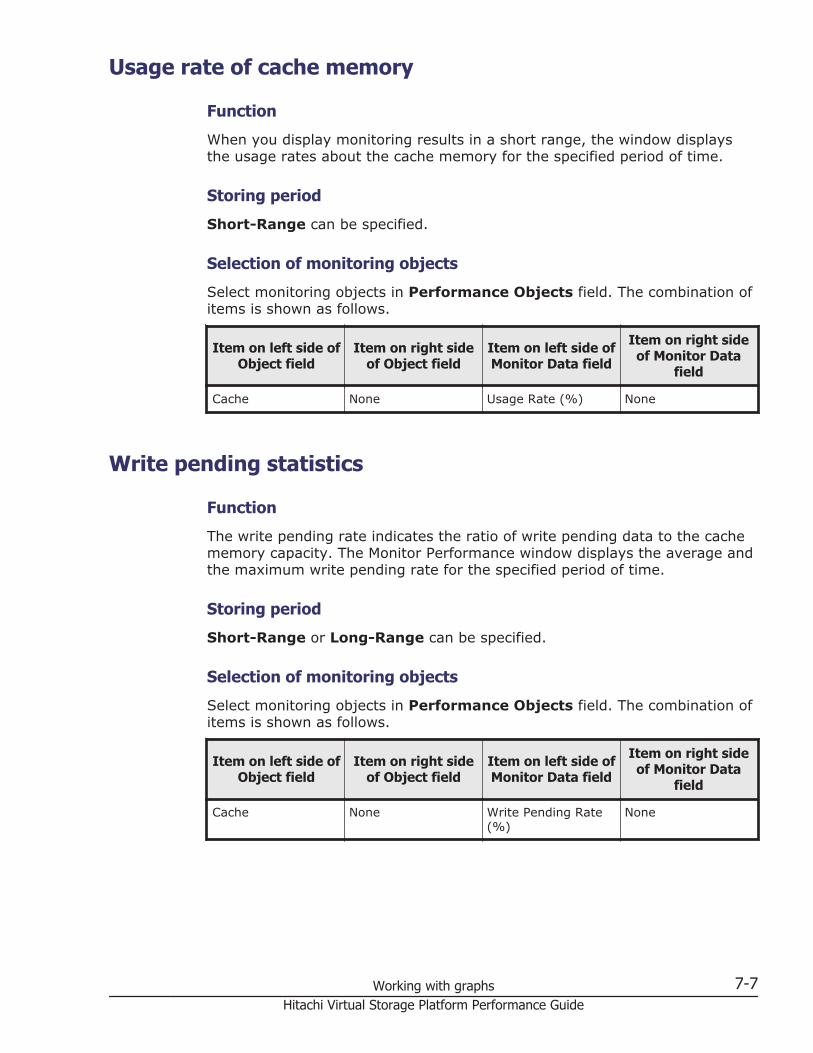
Usage rate of cache memory
Function
When you display monitoring results in a short range, the window displaysthe usage rates about the cache memory for the specified period of time.
Storing period
Short-Range can be specified.
Selection of monitoring objects
Select monitoring objects in Performance Objects field. The combination ofitems is shown as follows.
Item on left side ofObject field
Item on right sideof Object field
Item on left side ofMonitor Data field
Item on right sideof Monitor Data
field
Cache None Usage Rate (%) None
Write pending statistics
Function
The write pending rate indicates the ratio of write pending data to the cachememory capacity. The Monitor Performance window displays the average andthe maximum write pending rate for the specified period of time.
Storing period
Short-Range or Long-Range can be specified.
Selection of monitoring objects
Select monitoring objects in Performance Objects field. The combination ofitems is shown as follows.
Item on left side ofObject field
Item on right sideof Object field
Item on left side ofMonitor Data field
Item on right sideof Monitor Data
field
Cache None Write Pending Rate(%)
None
Working with graphs 7-7Hitachi Virtual Storage Platform Performance Guide
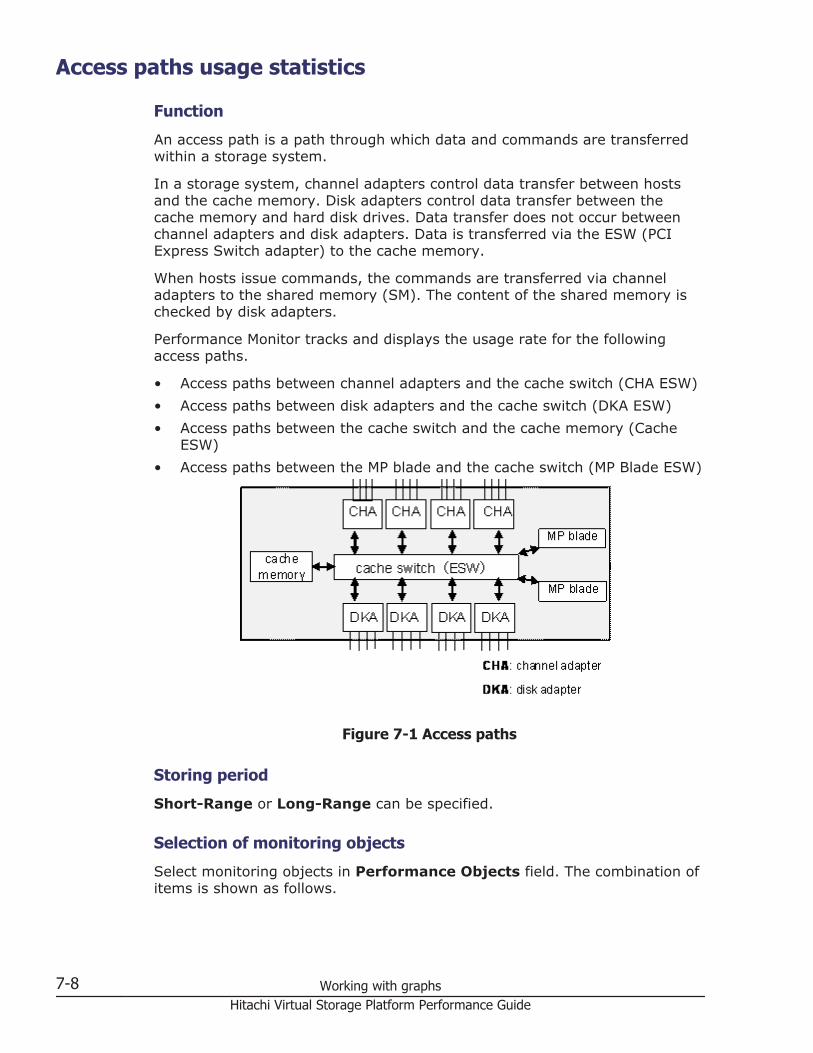
Access paths usage statistics
Function
An access path is a path through which data and commands are transferredwithin a storage system.
In a storage system, channel adapters control data transfer between hostsand the cache memory. Disk adapters control data transfer between thecache memory and hard disk drives. Data transfer does not occur betweenchannel adapters and disk adapters. Data is transferred via the ESW (PCIExpress Switch adapter) to the cache memory.
When hosts issue commands, the commands are transferred via channeladapters to the shared memory (SM). The content of the shared memory ischecked by disk adapters.
Performance Monitor tracks and displays the usage rate for the followingaccess paths.
• Access paths between channel adapters and the cache switch (CHA ESW)• Access paths between disk adapters and the cache switch (DKA ESW)• Access paths between the cache switch and the cache memory (Cache
ESW)• Access paths between the MP blade and the cache switch (MP Blade ESW)
Figure 7-1 Access paths
Storing period
Short-Range or Long-Range can be specified.
Selection of monitoring objects
Select monitoring objects in Performance Objects field. The combination ofitems is shown as follows.
7-8 Working with graphsHitachi Virtual Storage Platform Performance Guide
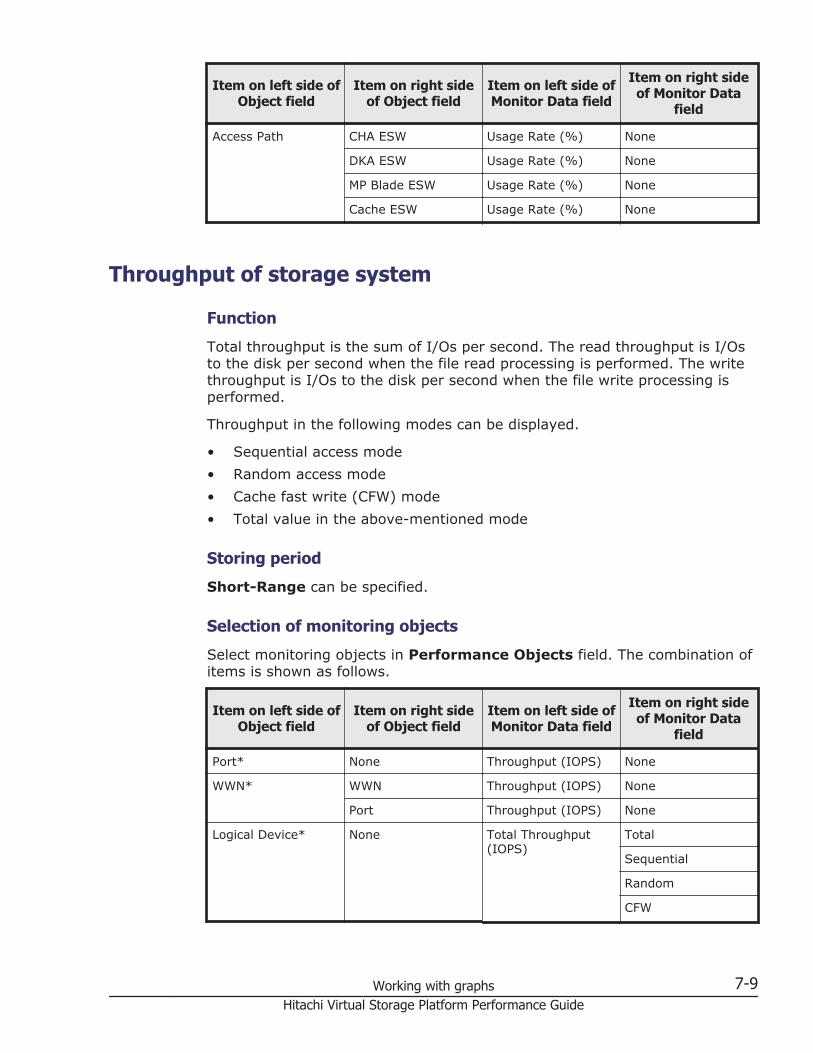
Item on left side ofObject field
Item on right sideof Object field
Item on left side ofMonitor Data field
Item on right sideof Monitor Data
field
Access Path CHA ESW Usage Rate (%) None
DKA ESW Usage Rate (%) None
MP Blade ESW Usage Rate (%) None
Cache ESW Usage Rate (%) None
Throughput of storage system
Function
Total throughput is the sum of I/Os per second. The read throughput is I/Osto the disk per second when the file read processing is performed. The writethroughput is I/Os to the disk per second when the file write processing isperformed.
Throughput in the following modes can be displayed.
• Sequential access mode• Random access mode• Cache fast write (CFW) mode• Total value in the above-mentioned mode
Storing period
Short-Range can be specified.
Selection of monitoring objects
Select monitoring objects in Performance Objects field. The combination ofitems is shown as follows.
Item on left side ofObject field
Item on right sideof Object field
Item on left side ofMonitor Data field
Item on right sideof Monitor Data
field
Port* None Throughput (IOPS) None
WWN* WWN Throughput (IOPS) None
Port Throughput (IOPS) None
Logical Device* None Total Throughput(IOPS)
Total
Sequential
Random
CFW
Working with graphs 7-9Hitachi Virtual Storage Platform Performance Guide
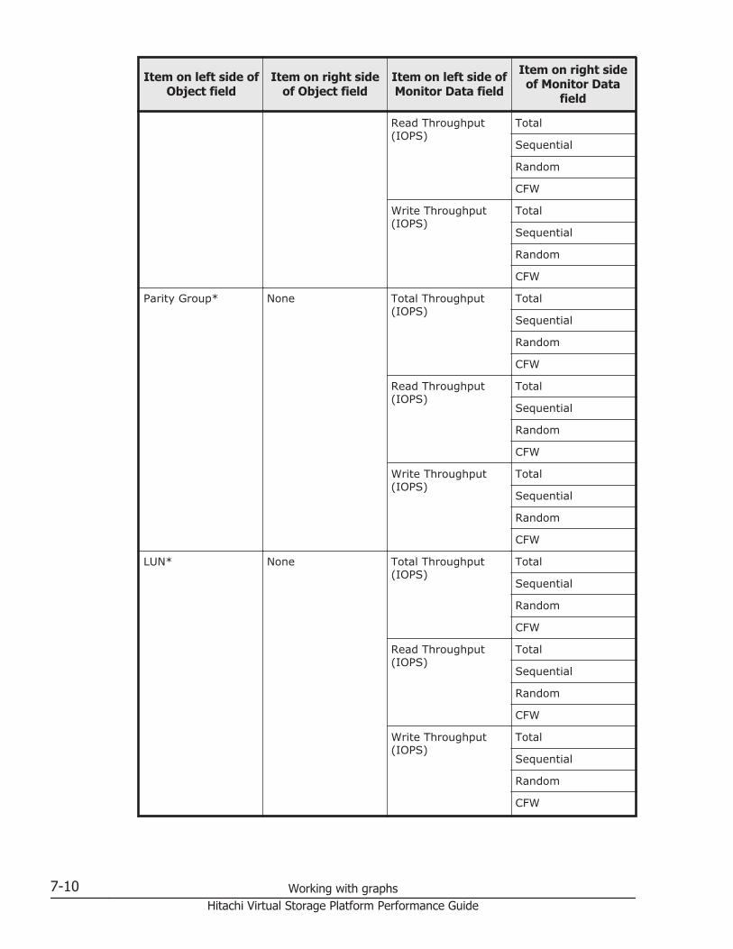
Item on left side ofObject field
Item on right sideof Object field
Item on left side ofMonitor Data field
Item on right sideof Monitor Data
field
Read Throughput(IOPS)
Total
Sequential
Random
CFW
Write Throughput(IOPS)
Total
Sequential
Random
CFW
Parity Group* None Total Throughput(IOPS)
Total
Sequential
Random
CFW
Read Throughput(IOPS)
Total
Sequential
Random
CFW
Write Throughput(IOPS)
Total
Sequential
Random
CFW
LUN* None Total Throughput(IOPS)
Total
Sequential
Random
CFW
Read Throughput(IOPS)
Total
Sequential
Random
CFW
Write Throughput(IOPS)
Total
Sequential
Random
CFW
7-10 Working with graphsHitachi Virtual Storage Platform Performance Guide
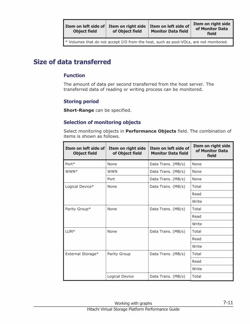
Item on left side ofObject field
Item on right sideof Object field
Item on left side ofMonitor Data field
Item on right sideof Monitor Data
field
* Volumes that do not accept I/O from the host, such as pool-VOLs, are not monitored.
Size of data transferred
Function
The amount of data per second transferred from the host server. Thetransferred data of reading or writing process can be monitored.
Storing period
Short-Range can be specified.
Selection of monitoring objects
Select monitoring objects in Performance Objects field. The combination ofitems is shown as follows.
Item on left side ofObject field
Item on right sideof Object field
Item on left side ofMonitor Data field
Item on right sideof Monitor Data
field
Port* None Data Trans. (MB/s) None
WWN* WWN Data Trans. (MB/s) None
Port Data Trans. (MB/s) None
Logical Device* None Data Trans. (MB/s) Total
Read
Write
Parity Group* None Data Trans. (MB/s) Total
Read
Write
LUN* None Data Trans. (MB/s) Total
Read
Write
External Storage* Parity Group Data Trans. (MB/s) Total
Read
Write
Logical Device Data Trans. (MB/s) Total
Working with graphs 7-11Hitachi Virtual Storage Platform Performance Guide
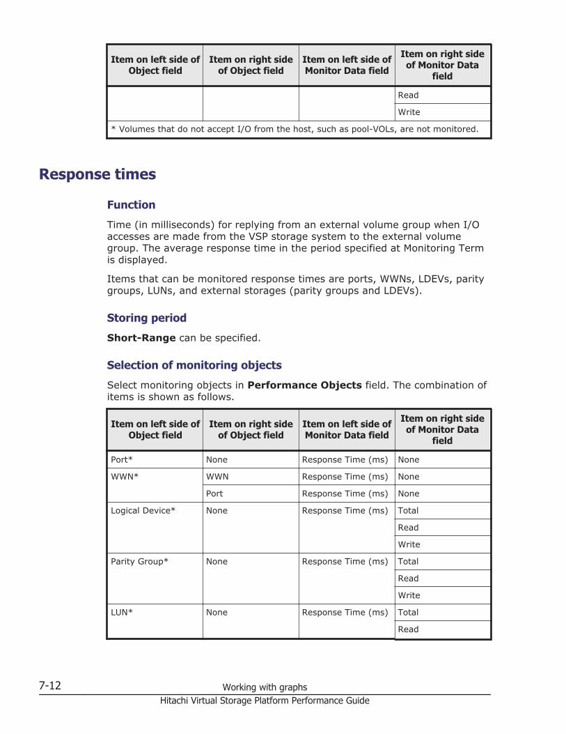
Item on left side ofObject field
Item on right sideof Object field
Item on left side ofMonitor Data field
Item on right sideof Monitor Data
field
Read
Write
* Volumes that do not accept I/O from the host, such as pool-VOLs, are not monitored.
Response times
Function
Time (in milliseconds) for replying from an external volume group when I/Oaccesses are made from the VSP storage system to the external volumegroup. The average response time in the period specified at Monitoring Termis displayed.
Items that can be monitored response times are ports, WWNs, LDEVs, paritygroups, LUNs, and external storages (parity groups and LDEVs).
Storing period
Short-Range can be specified.
Selection of monitoring objects
Select monitoring objects in Performance Objects field. The combination ofitems is shown as follows.
Item on left side ofObject field
Item on right sideof Object field
Item on left side ofMonitor Data field
Item on right sideof Monitor Data
field
Port* None Response Time (ms) None
WWN* WWN Response Time (ms) None
Port Response Time (ms) None
Logical Device* None Response Time (ms) Total
Read
Write
Parity Group* None Response Time (ms) Total
Read
Write
LUN* None Response Time (ms) Total
Read
7-12 Working with graphsHitachi Virtual Storage Platform Performance Guide
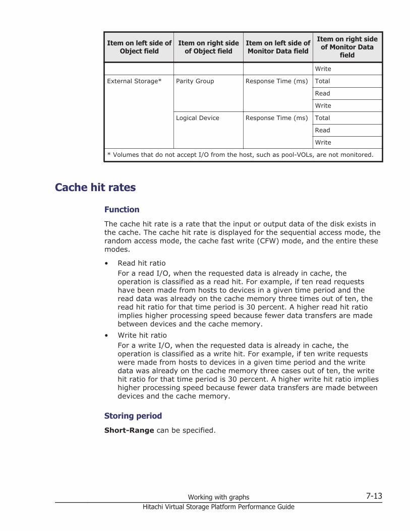
Item on left side ofObject field
Item on right sideof Object field
Item on left side ofMonitor Data field
Item on right sideof Monitor Data
field
Write
External Storage* Parity Group Response Time (ms) Total
Read
Write
Logical Device Response Time (ms) Total
Read
Write
* Volumes that do not accept I/O from the host, such as pool-VOLs, are not monitored.
Cache hit rates
Function
The cache hit rate is a rate that the input or output data of the disk exists inthe cache. The cache hit rate is displayed for the sequential access mode, therandom access mode, the cache fast write (CFW) mode, and the entire thesemodes.
• Read hit ratioFor a read I/O, when the requested data is already in cache, theoperation is classified as a read hit. For example, if ten read requestshave been made from hosts to devices in a given time period and theread data was already on the cache memory three times out of ten, theread hit ratio for that time period is 30 percent. A higher read hit ratioimplies higher processing speed because fewer data transfers are madebetween devices and the cache memory.
• Write hit ratioFor a write I/O, when the requested data is already in cache, theoperation is classified as a write hit. For example, if ten write requestswere made from hosts to devices in a given time period and the writedata was already on the cache memory three cases out of ten, the writehit ratio for that time period is 30 percent. A higher write hit ratio implieshigher processing speed because fewer data transfers are made betweendevices and the cache memory.
Storing period
Short-Range can be specified.
Working with graphs 7-13Hitachi Virtual Storage Platform Performance Guide
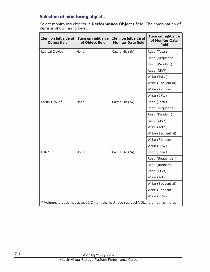
Selection of monitoring objects
Select monitoring objects in Performance Objects field. The combination ofitems is shown as follows.
Item on left side ofObject field
Item on right sideof Objecc field
Item on left side ofMonitor Data field
Item on right sideof Monitor Data
field
Logical Device* None Cache Hit (%) Read (Total)
Read (Sequential)
Read (Random)
Read (CFW)
Write (Total)
Write (Sequential)
Write (Random)
Write (CFW)
Parity Group* None Cache Hit (%) Read (Total)
Read (Sequential)
Read (Random)
Read (CFW)
Write (Total)
Write (Sequential)
Write (Random)
Write (CFW)
LUN* None Cache Hit (%) Read (Total)
Read (Sequential)
Read (Random)
Read (CFW)
Write (Total)
Write (Sequential)
Write (Random)
Write (CFW)
* Volumes that do not accept I/O from the host, such as pool-VOLs, are not monitored.
7-14 Working with graphsHitachi Virtual Storage Platform Performance Guide
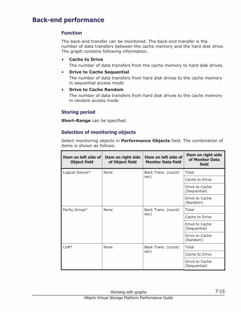
Back-end performance
Function
The back-end transfer can be monitored. The back-end transfer is thenumber of data transfers between the cache memory and the hard disk drive.The graph contains following information.
• Cache to DriveThe number of data transfers from the cache memory to hard disk drives.
• Drive to Cache SequentialThe number of data transfers from hard disk drives to the cache memoryin sequential access mode
• Drive to Cache RandomThe number of data transfers from hard disk drives to the cache memoryin random access mode
Storing period
Short-Range can be specified.
Selection of monitoring objects
Select monitoring objects in Performance Objects field. The combination ofitems is shown as follows.
Item on left side ofObject field
Item on right sideof Object field
Item on left side ofMonitor Data field
Item on right sideof Monitor Data
field
Logical Device* None Back Trans. (count/sec)
Total
Cache to Drive
Drive to Cache(Sequential)
Drive to Cache(Random)
Parity Group* None Back Trans. (count/sec)
Total
Cache to Drive
Drive to Cache(Sequential)
Drive to Cache(Random)
LUN* None Back Trans. (count/sec)
Total
Cache to Drive
Drive to Cache(Sequential)
Working with graphs 7-15Hitachi Virtual Storage Platform Performance Guide
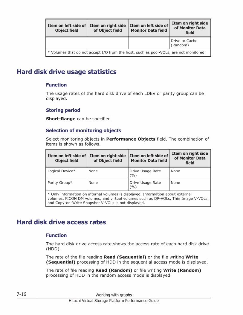
Item on left side ofObject field
Item on right sideof Object field
Item on left side ofMonitor Data field
Item on right sideof Monitor Data
field
Drive to Cache(Random)
* Volumes that do not accept I/O from the host, such as pool-VOLs, are not monitored.
Hard disk drive usage statistics
Function
The usage rates of the hard disk drive of each LDEV or parity group can bedisplayed.
Storing period
Short-Range can be specified.
Selection of monitoring objects
Select monitoring objects in Performance Objects field. The combination ofitems is shown as follows.
Item on left side ofObject field
Item on right sideof Object field
Item on left side ofMonitor Data field
Item on right sideof Monitor Data
field
Logical Device* None Drive Usage Rate(%)
None
Parity Group* None Drive Usage Rate(%)
None
* Only information on internal volumes is displayed. Information about externalvolumes, FICON DM volumes, and virtual volumes such as DP-VOLs, Thin Image V-VOLs,and Copy-on-Write Snapshot V-VOLs is not displayed.
Hard disk drive access rates
Function
The hard disk drive access rate shows the access rate of each hard disk drive(HDD).
The rate of the file reading Read (Sequential) or the file writing Write(Sequential) processing of HDD in the sequential access mode is displayed.
The rate of file reading Read (Random) or file writing Write (Random)processing of HDD in the random access mode is displayed.
7-16 Working with graphsHitachi Virtual Storage Platform Performance Guide

Storing period
Long-Range or Short-Range can be specified.
Selection of monitoring objects
Select monitoring objects in Performance Objects field. The combination ofitems is shown as follows.
Item on left side ofObject field
Item on right sideof Object field
Item on left side ofMonitor Data field
Item on right sideof Monitor Data
field
Logical Device* None Drive Access Rate(%)
Read (Sequential)
Read (Random)
Write (Sequential)
Write (Random)
* Only information on internal volumes is displayed. Information about externalvolumes, FICON DM volumes, and virtual volumes such as DP-VOLs, Thin Image V-VOLs,and Copy-on-Write Snapshot V-VOLs is not displayed.
ShadowImage usage statistics
Function
The access rate of volume by ShadowImage can be displayed the percentageof the processing of the program to all the processing of the physical drives,for each volume. This value is found by dividing access time to physical drivesby the program by all the access time to physical drives.
Storing period
Short-Range can be specified.
Selection of monitoring objects
Select monitoring objects in Performance Objects field. The combination ofitems is shown as follows.
Item on left side ofObject field
Item on right sideof Object field
Item on left side ofMonitor Data field
Item on right sideof Monitor Data
field
Logical Device* None ShadowImage (%) None
* Only information on internal volumes is displayed. Information about externalvolumes, FICON DM volumes, and virtual volumes such as DP-VOLs, Thin Image V-VOLs,and Copy-on-Write Snapshot V-VOLs is not displayed.
Working with graphs 7-17Hitachi Virtual Storage Platform Performance Guide
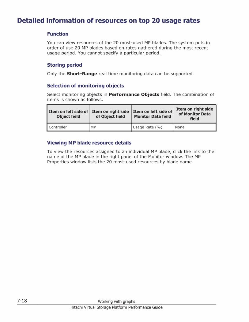
Detailed information of resources on top 20 usage rates
Function
You can view resources of the 20 most-used MP blades. The system puts inorder of use 20 MP blades based on rates gathered during the most recentusage period. You cannot specify a particular period.
Storing period
Only the Short-Range real time monitoring data can be supported.
Selection of monitoring objects
Select monitoring objects in Performance Objects field. The combination ofitems is shown as follows.
Item on left side ofObject field
Item on right sideof Object field
Item on left side ofMonitor Data field
Item on right sideof Monitor Data
field
Controller MP Usage Rate (%) None
Viewing MP blade resource details
To view the resources assigned to an individual MP blade, click the link to thename of the MP blade in the right panel of the Monitor window. The MPProperties window lists the 20 most-used resources by blade name.
7-18 Working with graphsHitachi Virtual Storage Platform Performance Guide
8Changing display of graphs
This topic describes how to change displaying of graphs.
□ Graph operation
□ Changing displayed items
□ Changing a display period
□ Adding a new graph
□ Deleting graph panel
Changing display of graphs 8-1Hitachi Virtual Storage Platform Performance Guide
Graph operationInformation displayed in the graph can be changed. The following operationscan be performed:
• Displayed items in the graph can be changed.For details, see Changing displayed items on page 8-2.
• Displayed periods in the graph can be changed.For details, see Changing a display period on page 8-2
• New graphs can be added.For details, see Adding a new graph on page 8-3.
• Graph panels can be deleted.For detail, see Deleting graph panel on page 8-3.
Changing displayed itemsTo change displayed items in the graph:
1. Display a graph in the Monitor Performance window.For details, see Basic operation on page 7-3.
2. Click Edit Performance Objects.The Edit Performance Objects window opens.
3. Change displayed items in the information setting field at the left of thewindow.For details, see Basic operation on page 7-3.
4. Click Add.Items are added in the Selected Objects field.
5. If you want to delete the item, select the item and then click Remove.6. Click OK.
The graph is displayed.
Changing a display periodTo change a display period in the graph:
1. Display graph in the Monitor Performance window.For details, see Basic operation on page 7-3.
2. Click Edit Time Range.The Edit Time Range window opens.
3. Input the date when the display of the graph begins in the From field.Input the date when the display of the graph is ended in the To field.
4. Click OK.The graph is displayed.
8-2 Changing display of graphsHitachi Virtual Storage Platform Performance Guide
Adding a new graph To add a new graph:
1. Display graph in the Monitor Performance window.For details, see Basic operation on page 7-3.
2. Click Add Graph.The Add Graph window opens.
3. Change displayed items in the information setting field at the left of thewindow.For details, see Basic operation on page 7-3.
4. Click Add.Items are added in the Selected Objects field.
5. If you want to delete the item, select the item and then click Remove.6. Click OK.
The graph is added.
Deleting graph panelTo delete a graph panel:
1. Display graph in the Monitor Performance window.For details, see Basic operation on page 7-3.
2. Click Delete Graph or the icon to close the window displayed in the upperright of the graph panel.A warning message appears, asking whether you want to delete the graphpanel.
3. Click OK to close the message.The graph panel is deleted.
Changing display of graphs 8-3Hitachi Virtual Storage Platform Performance Guide

8-4 Changing display of graphsHitachi Virtual Storage Platform Performance Guide
9Server Priority Manager operations
This topic provides information and instructions for using Server PriorityManager software to perform upper-limit control.
□ Overview of Server Priority Manager operations
□ If one-to-one connections link HBAs and ports
□ If many-to-many connections link HBAs and ports
□ Port tab operations
□ WWN tab operations
Server Priority Manager operations 9-1Hitachi Virtual Storage Platform Performance Guide
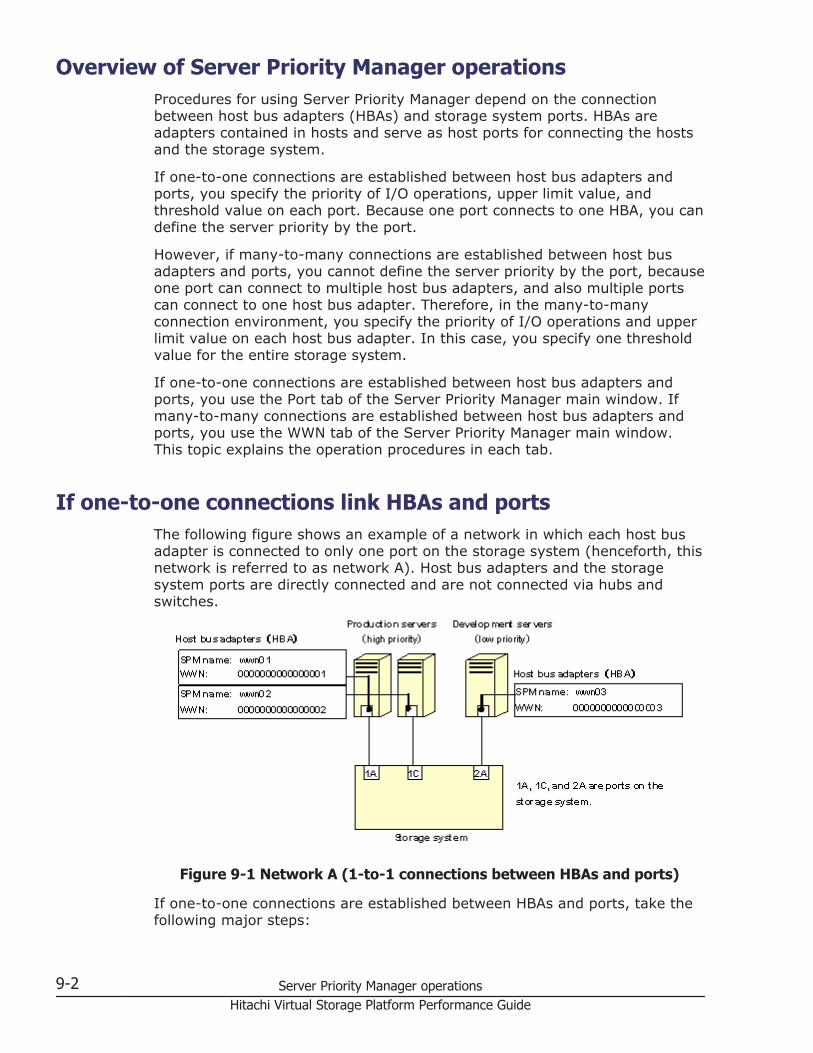
Overview of Server Priority Manager operationsProcedures for using Server Priority Manager depend on the connectionbetween host bus adapters (HBAs) and storage system ports. HBAs areadapters contained in hosts and serve as host ports for connecting the hostsand the storage system.
If one-to-one connections are established between host bus adapters andports, you specify the priority of I/O operations, upper limit value, andthreshold value on each port. Because one port connects to one HBA, you candefine the server priority by the port.
However, if many-to-many connections are established between host busadapters and ports, you cannot define the server priority by the port, becauseone port can connect to multiple host bus adapters, and also multiple portscan connect to one host bus adapter. Therefore, in the many-to-manyconnection environment, you specify the priority of I/O operations and upperlimit value on each host bus adapter. In this case, you specify one thresholdvalue for the entire storage system.
If one-to-one connections are established between host bus adapters andports, you use the Port tab of the Server Priority Manager main window. Ifmany-to-many connections are established between host bus adapters andports, you use the WWN tab of the Server Priority Manager main window.This topic explains the operation procedures in each tab.
If one-to-one connections link HBAs and portsThe following figure shows an example of a network in which each host busadapter is connected to only one port on the storage system (henceforth, thisnetwork is referred to as network A). Host bus adapters and the storagesystem ports are directly connected and are not connected via hubs andswitches.
Figure 9-1 Network A (1-to-1 connections between HBAs and ports)
If one-to-one connections are established between HBAs and ports, take thefollowing major steps:
9-2 Server Priority Manager operationsHitachi Virtual Storage Platform Performance Guide
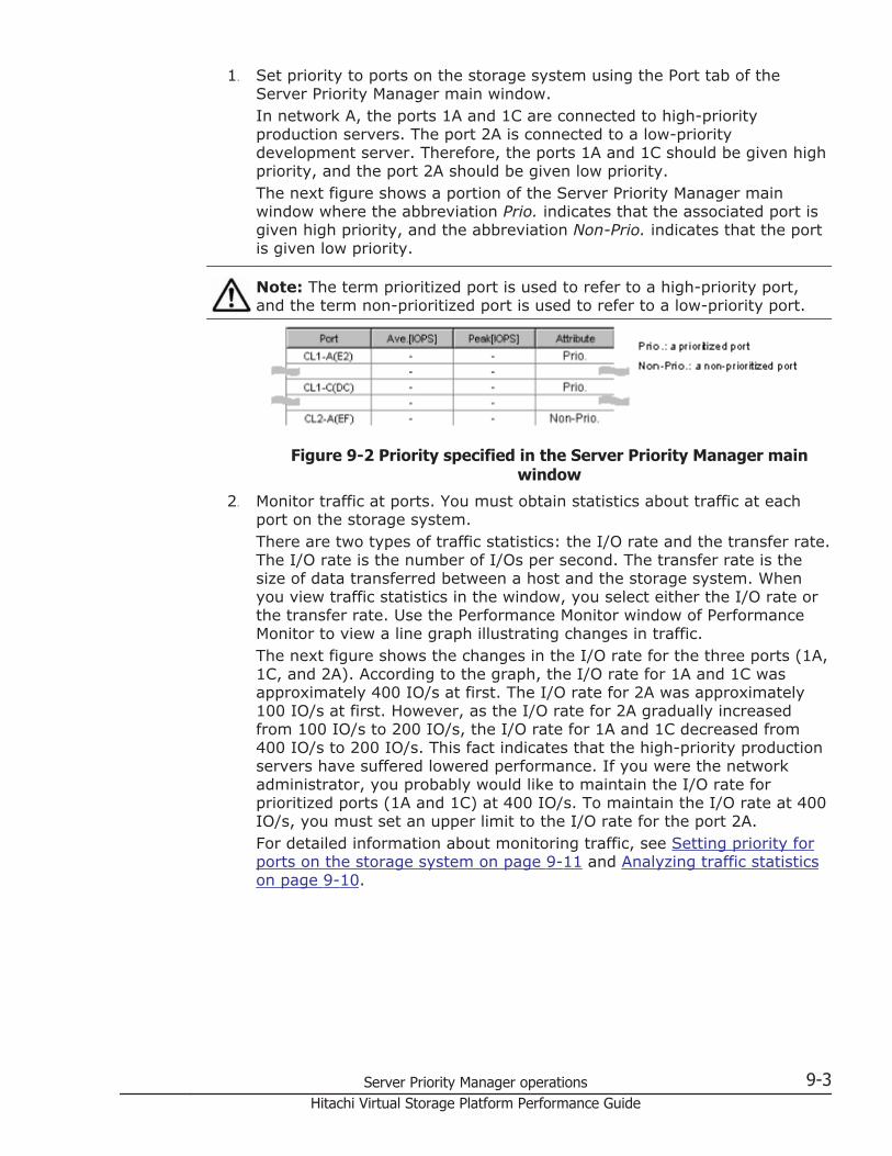
1. Set priority to ports on the storage system using the Port tab of theServer Priority Manager main window.In network A, the ports 1A and 1C are connected to high-priorityproduction servers. The port 2A is connected to a low-prioritydevelopment server. Therefore, the ports 1A and 1C should be given highpriority, and the port 2A should be given low priority.The next figure shows a portion of the Server Priority Manager mainwindow where the abbreviation Prio. indicates that the associated port isgiven high priority, and the abbreviation Non-Prio. indicates that the portis given low priority.
Note: The term prioritized port is used to refer to a high-priority port,and the term non-prioritized port is used to refer to a low-priority port.
Figure 9-2 Priority specified in the Server Priority Manager mainwindow
2. Monitor traffic at ports. You must obtain statistics about traffic at eachport on the storage system.There are two types of traffic statistics: the I/O rate and the transfer rate.The I/O rate is the number of I/Os per second. The transfer rate is thesize of data transferred between a host and the storage system. Whenyou view traffic statistics in the window, you select either the I/O rate orthe transfer rate. Use the Performance Monitor window of PerformanceMonitor to view a line graph illustrating changes in traffic.The next figure shows the changes in the I/O rate for the three ports (1A,1C, and 2A). According to the graph, the I/O rate for 1A and 1C wasapproximately 400 IO/s at first. The I/O rate for 2A was approximately100 IO/s at first. However, as the I/O rate for 2A gradually increasedfrom 100 IO/s to 200 IO/s, the I/O rate for 1A and 1C decreased from400 IO/s to 200 IO/s. This fact indicates that the high-priority productionservers have suffered lowered performance. If you were the networkadministrator, you probably would like to maintain the I/O rate forprioritized ports (1A and 1C) at 400 IO/s. To maintain the I/O rate at 400IO/s, you must set an upper limit to the I/O rate for the port 2A.For detailed information about monitoring traffic, see Setting priority forports on the storage system on page 9-11 and Analyzing traffic statisticson page 9-10.
Server Priority Manager operations 9-3Hitachi Virtual Storage Platform Performance Guide
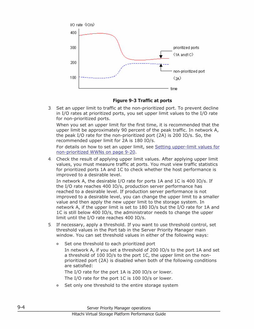
Figure 9-3 Traffic at ports
3. Set an upper limit to traffic at the non-prioritized port. To prevent declinein I/O rates at prioritized ports, you set upper limit values to the I/O ratefor non-prioritized ports.When you set an upper limit for the first time, it is recommended that theupper limit be approximately 90 percent of the peak traffic. In network A,the peak I/O rate for the non-prioritized port (2A) is 200 IO/s. So, therecommended upper limit for 2A is 180 IO/s.For details on how to set an upper limit, see Setting upper-limit values fornon-prioritized WWNs on page 9-20.
4. Check the result of applying upper limit values. After applying upper limitvalues, you must measure traffic at ports. You must view traffic statisticsfor prioritized ports 1A and 1C to check whether the host performance isimproved to a desirable level.In network A, the desirable I/O rate for ports 1A and 1C is 400 IO/s. Ifthe I/O rate reaches 400 IO/s, production server performance hasreached to a desirable level. If production server performance is notimproved to a desirable level, you can change the upper limit to a smallervalue and then apply the new upper limit to the storage system. Innetwork A, if the upper limit is set to 180 IO/s but the I/O rate for 1A and1C is still below 400 IO/s, the administrator needs to change the upperlimit until the I/O rate reaches 400 IO/s.
5. If necessary, apply a threshold. If you want to use threshold control, setthreshold values in the Port tab in the Server Priority Manager mainwindow. You can set threshold values in either of the following ways:
¢ Set one threshold to each prioritized portIn network A, if you set a threshold of 200 IO/s to the port 1A and seta threshold of 100 IO/s to the port 1C, the upper limit on the non-prioritized port (2A) is disabled when both of the following conditionsare satisfied:The I/O rate for the port 1A is 200 IO/s or lower.The I/O rate for the port 1C is 100 IO/s or lower.
¢ Set only one threshold to the entire storage system
9-4 Server Priority Manager operationsHitachi Virtual Storage Platform Performance Guide
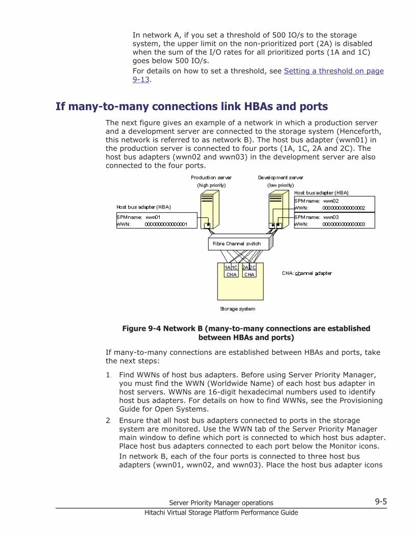
In network A, if you set a threshold of 500 IO/s to the storagesystem, the upper limit on the non-prioritized port (2A) is disabledwhen the sum of the I/O rates for all prioritized ports (1A and 1C)goes below 500 IO/s.For details on how to set a threshold, see Setting a threshold on page9-13.
If many-to-many connections link HBAs and portsThe next figure gives an example of a network in which a production serverand a development server are connected to the storage system (Henceforth,this network is referred to as network B). The host bus adapter (wwn01) inthe production server is connected to four ports (1A, 1C, 2A and 2C). Thehost bus adapters (wwn02 and wwn03) in the development server are alsoconnected to the four ports.
Figure 9-4 Network B (many-to-many connections are establishedbetween HBAs and ports)
If many-to-many connections are established between HBAs and ports, takethe next steps:
1. Find WWNs of host bus adapters. Before using Server Priority Manager,you must find the WWN (Worldwide Name) of each host bus adapter inhost servers. WWNs are 16-digit hexadecimal numbers used to identifyhost bus adapters. For details on how to find WWNs, see the ProvisioningGuide for Open Systems.
2. Ensure that all host bus adapters connected to ports in the storagesystem are monitored. Use the WWN tab of the Server Priority Managermain window to define which port is connected to which host bus adapter.Place host bus adapters connected to each port below the Monitor icons.In network B, each of the four ports is connected to three host busadapters (wwn01, wwn02, and wwn03). Place the host bus adapter icons
Server Priority Manager operations 9-5Hitachi Virtual Storage Platform Performance Guide
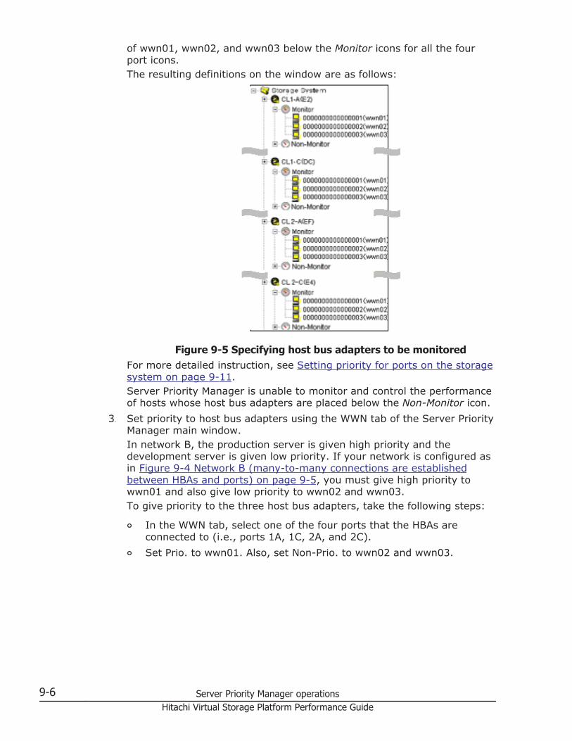
of wwn01, wwn02, and wwn03 below the Monitor icons for all the fourport icons.The resulting definitions on the window are as follows:
Figure 9-5 Specifying host bus adapters to be monitoredFor more detailed instruction, see Setting priority for ports on the storagesystem on page 9-11.Server Priority Manager is unable to monitor and control the performanceof hosts whose host bus adapters are placed below the Non-Monitor icon.
3. Set priority to host bus adapters using the WWN tab of the Server PriorityManager main window.In network B, the production server is given high priority and thedevelopment server is given low priority. If your network is configured asin Figure 9-4 Network B (many-to-many connections are establishedbetween HBAs and ports) on page 9-5, you must give high priority towwn01 and also give low priority to wwn02 and wwn03.To give priority to the three host bus adapters, take the following steps:
¢ In the WWN tab, select one of the four ports that the HBAs areconnected to (i.e., ports 1A, 1C, 2A, and 2C).
¢ Set Prio. to wwn01. Also, set Non-Prio. to wwn02 and wwn03.
9-6 Server Priority Manager operationsHitachi Virtual Storage Platform Performance Guide
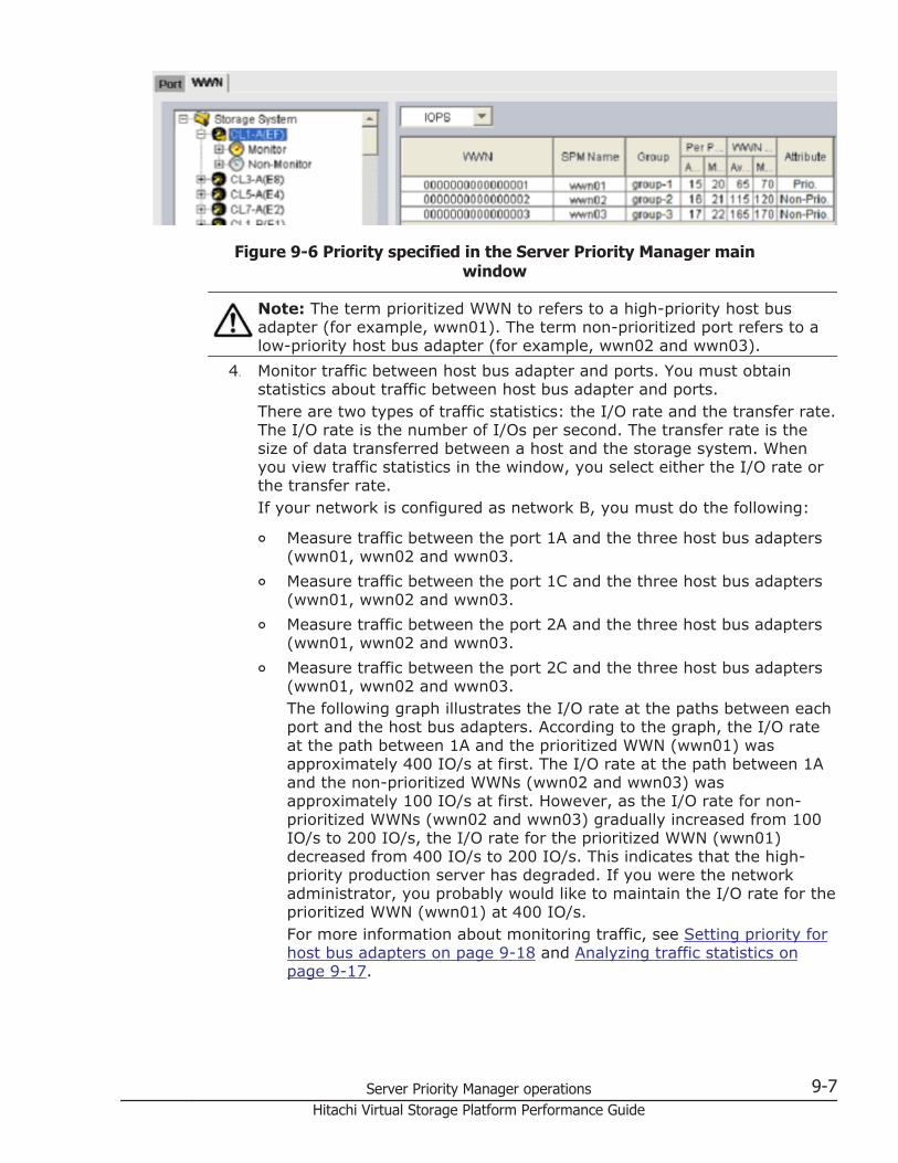
Figure 9-6 Priority specified in the Server Priority Manager mainwindow
Note: The term prioritized WWN to refers to a high-priority host busadapter (for example, wwn01). The term non-prioritized port refers to alow-priority host bus adapter (for example, wwn02 and wwn03).
4. Monitor traffic between host bus adapter and ports. You must obtainstatistics about traffic between host bus adapter and ports.There are two types of traffic statistics: the I/O rate and the transfer rate.The I/O rate is the number of I/Os per second. The transfer rate is thesize of data transferred between a host and the storage system. Whenyou view traffic statistics in the window, you select either the I/O rate orthe transfer rate.If your network is configured as network B, you must do the following:
¢ Measure traffic between the port 1A and the three host bus adapters(wwn01, wwn02 and wwn03.
¢ Measure traffic between the port 1C and the three host bus adapters(wwn01, wwn02 and wwn03.
¢ Measure traffic between the port 2A and the three host bus adapters(wwn01, wwn02 and wwn03.
¢ Measure traffic between the port 2C and the three host bus adapters(wwn01, wwn02 and wwn03.The following graph illustrates the I/O rate at the paths between eachport and the host bus adapters. According to the graph, the I/O rateat the path between 1A and the prioritized WWN (wwn01) wasapproximately 400 IO/s at first. The I/O rate at the path between 1Aand the non-prioritized WWNs (wwn02 and wwn03) wasapproximately 100 IO/s at first. However, as the I/O rate for non-prioritized WWNs (wwn02 and wwn03) gradually increased from 100IO/s to 200 IO/s, the I/O rate for the prioritized WWN (wwn01)decreased from 400 IO/s to 200 IO/s. This indicates that the high-priority production server has degraded. If you were the networkadministrator, you probably would like to maintain the I/O rate for theprioritized WWN (wwn01) at 400 IO/s.For more information about monitoring traffic, see Setting priority forhost bus adapters on page 9-18 and Analyzing traffic statistics onpage 9-17.
Server Priority Manager operations 9-7Hitachi Virtual Storage Platform Performance Guide
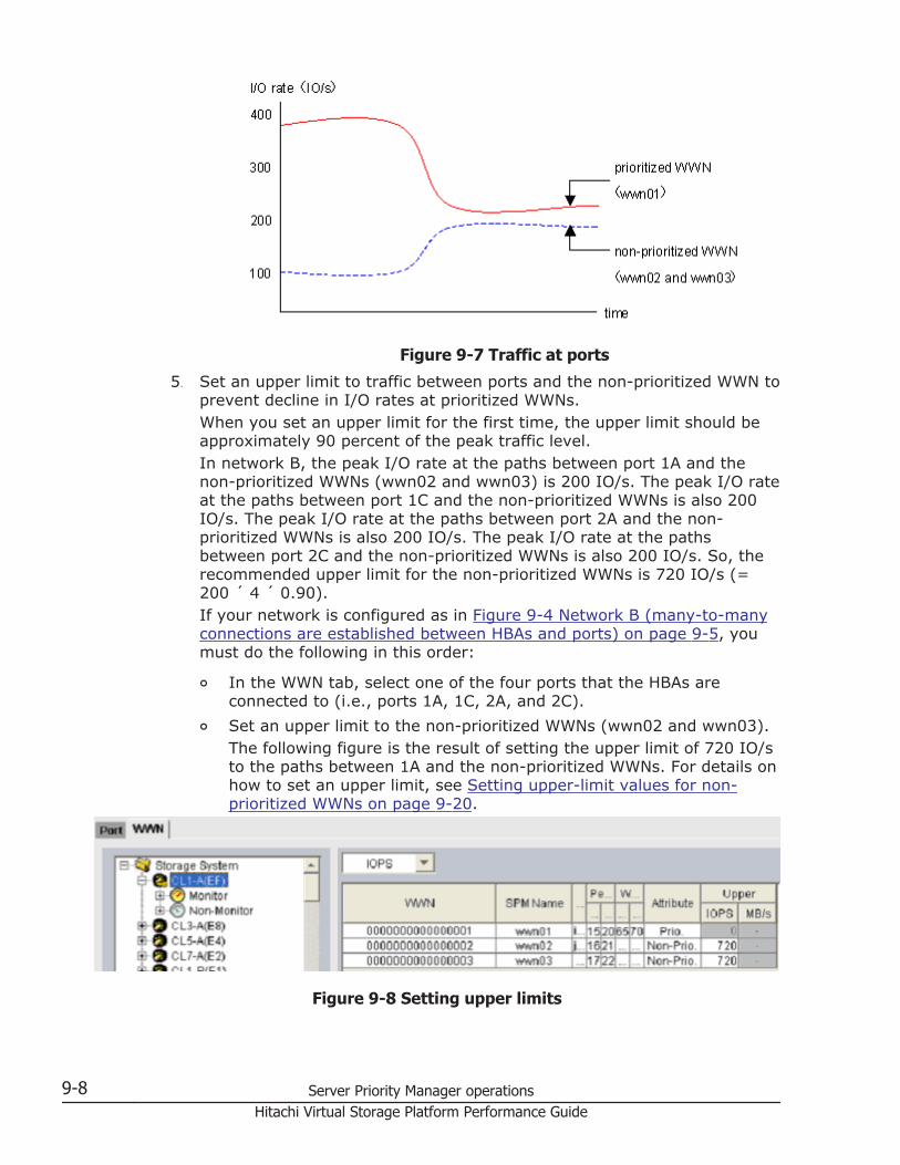
Figure 9-7 Traffic at ports
5. Set an upper limit to traffic between ports and the non-prioritized WWN toprevent decline in I/O rates at prioritized WWNs.When you set an upper limit for the first time, the upper limit should beapproximately 90 percent of the peak traffic level.In network B, the peak I/O rate at the paths between port 1A and thenon-prioritized WWNs (wwn02 and wwn03) is 200 IO/s. The peak I/O rateat the paths between port 1C and the non-prioritized WWNs is also 200IO/s. The peak I/O rate at the paths between port 2A and the non-prioritized WWNs is also 200 IO/s. The peak I/O rate at the pathsbetween port 2C and the non-prioritized WWNs is also 200 IO/s. So, therecommended upper limit for the non-prioritized WWNs is 720 IO/s (=200 ´ 4 ´ 0.90).If your network is configured as in Figure 9-4 Network B (many-to-manyconnections are established between HBAs and ports) on page 9-5, youmust do the following in this order:
¢ In the WWN tab, select one of the four ports that the HBAs areconnected to (i.e., ports 1A, 1C, 2A, and 2C).
¢ Set an upper limit to the non-prioritized WWNs (wwn02 and wwn03).The following figure is the result of setting the upper limit of 720 IO/sto the paths between 1A and the non-prioritized WWNs. For details onhow to set an upper limit, see Setting upper-limit values for non-prioritized WWNs on page 9-20.
Figure 9-8 Setting upper limits
9-8 Server Priority Manager operationsHitachi Virtual Storage Platform Performance Guide
6. Check the result of applying upper limit values. After applying upper limitvalues, you must measure traffic at ports. View traffic statistics for theprioritized WWN to check whether the host performance is improved to adesirable level.In network B, the desirable I/O rate for the prioritized WWN is 400 IO/s.If the I/O rate reaches 400 IO/s, production server performance hasreached to a desirable level. If production server performance is notimproved to a desirable level, you can change the upper limit to a smallervalue and then apply the new upper limit to the storage system. Innetwork B, if the upper limit is set to 720 IO/s but the I/O rate for wwn01is still below 400 IO/s, the administrator needs to change the upper limituntil the I/O rate reaches 400 IO/s.If an upper limit of the non-prioritized WWN is set to zero or nearly zero,I/O performance might be lowered. If I/O performance is lowered, thehost cannot be connected to the storage system in some cases.
7. If necessary, apply a threshold. If you want to use threshold control, set athreshold in the WWN tab in the Server Priority Manager main window.In the WWN tab, you can specify only one threshold for the entire storagesystem, regardless of the number of prioritized WWNs. For example, ifthere are three prioritized WWNs in the network and the threshold is 100IO/s, the upper limit on the non-prioritized WWNs is disabled when thesum of the I/O rates for all prioritized WWNs goes below 100 IO/s.For details on how to set a threshold, see Setting a threshold on page9-21.
Caution: If you enter zero (0) in a cell to disable the upper limit, the celldisplays a hyphen (-) and the threshold for the prioritized port becomesineffective. If the thresholds of all the prioritized ports are ineffective,threshold control will not be performed but upper limit control will beperformed.The following table shows the relationship between thresholds of aprioritized WWN and the upper limits of a non-prioritized WWN.
Table 9-1 Prioritized WWN threshold setting relationships
Thresholdsettings
A number other than zero isset to the upper limit of the
non-prioritized WWN
Zero is set to the upper limit ofthe non-prioritized WWN
Threshold Is Setto ThePrioritized WWN
When thresholds are set toprioritized WWNs, depending onthe I/O rate or the transfer rate,the following controls areexecuted.• If the total value of I/O rate
or transfer rate exceeds thethreshold in all prioritizedWWNs, upper limits of all thenon-prioritized WWNs takeeffect.
• If the total value of I/O rateor transfer rate goes below
The threshold control of theprioritized WWN is not executed.
Server Priority Manager operations 9-9Hitachi Virtual Storage Platform Performance Guide
Thresholdsettings
A number other than zero isset to the upper limit of the
non-prioritized WWN
Zero is set to the upper limit ofthe non-prioritized WWN
the threshold in all prioritizedWWNs, upper limits of all thenon-prioritized WWNs do nottake effect.
Threshold Is NotSet to ThePrioritized WWN
The specified upper limit alwaystakes effect.
Port tab operationsIf one-to-one connections are established between host bus adapters (HBAs)and storage system ports, use the Port tab in the Server Priority Managermain window to do the following:
• Analyze traffic statistics• Measure traffic between host bus adapters and storage system ports• Set priority to ports on the storage system• Set an upper limit to traffic at each non-prioritized port• Set a threshold to the storage system or to each prioritized port, if
necessary
If one-to-one connections are established between host bus adapters andports, you should specify the priority of I/O operations on each port. You canspecify the upper limit values on the non-prioritized ports, and if necessary,you can also specify the threshold values on the prioritized ports. Moreover,you can use one threshold value applied for the entire storage system.
For details on the system configuration of one-to-one connections betweenhost bus adapters and ports, see If one-to-one connections link HBAs andports on page 9-2. This topic explains operation procedures you can performfor ports and the entire storage system.
Analyzing traffic statisticsThe traffic statistics reveal the number of I/Os that have been made viaports. The traffic statistics also reveal the amount of data that have beentransferred via ports. You must analyze the traffic statistics to determineupper limit values that should be applied to I/O rates or transfer rates fornon-prioritized ports.
The following is the procedure for using the Server Priority Manager mainwindow to analyze traffic statistics. You can also use the Performance Monitorwindow to analyze traffic statistics. Performance Monitor can display a linegraph that indicates changes in traffic.
1. Click Reports > Performance Monitor> Server Priority Manager toopen the Server Priority Manager window.
9-10 Server Priority Manager operationsHitachi Virtual Storage Platform Performance Guide
2.
Click to change to Modify mode.3. In the Server Priority Manager window, click Server Priority Manager.
The Server Priority Manager main window appears.4. Select the Port tab.5. Select All from the list at the top right corner of the window.6. Do one of the following:
¢ To analyze I/O rates, select IOPS from the list at the upper leftcorner of the list.
¢ To analyze transfer rates, select MB/s from the list at the upper leftcorner of the list.The list displays traffic statistics (i.e., the average and peak I/O ratesor transfer rates) of the ports.
7. Analyze the information in the list and then determine upper limit valuesthat should be applied to non-prioritized ports. If necessary, determinethreshold values that should be applied to prioritized ports. For details onthe upper limit values and threshold values, see If one-to-oneconnections link HBAs and ports on page 9-2.
Setting priority for ports on the storage systemIf one-to-one connection is established between HBAs and ports, you need tomeasure traffic between high-priority HBAs and prioritized ports. You alsoneed to measure traffic between low-priority HBAs and non-prioritized ports.
Prioritized ports are ports on which the processing has high priority and non-prioritized ports are ports on which the processing has low priority. Specify aport that connects to a high-priority host bus adapter as a prioritized port.Specify a port that connects to a low-priority host bus adapter as a non-prioritized port.
1. Click Reports >Performance Monitor> Server Priority Manager to openthe Server Priority Manager window.
2.
Click to change to Modify mode.3. In the Server Priority Manager window, click Server Priority Manager.
The Server Priority Manager main window appears.4. Ensure that the Port tab is displayed.5. Select All from the list at the top right corner of the window.6. Right-click a high-priority port and then select Non-Prio ->> Prio from
the pop-up menu. If there is more than one high-priority port, repeat thisoperation. The Attribute column displays Prio.
7. Right-click a low-priority port and then select Prio ->> Non-Prio fromthe pop-up menu. If there is more than one low-priority port, repeat thisoperation.The Attribute column displays Non-Prio.
Server Priority Manager operations 9-11Hitachi Virtual Storage Platform Performance Guide
You must set upper limit values for the Non-prio. specified ports. Fordetail about the setting of upper limit values, see Setting upper-limitvalues to traffic at non-prioritized ports on page 9-12.
8. Click Apply. The settings on the window are applied to the storagesystem.
After priority has been set, you can implement the procedure for measuringtraffic (I/O rates and transfer rates). See Chapter 5, Monitoring operation onpage 5-1.
Setting upper-limit values to traffic at non-prioritized portsAfter you analyze traffic statistics, you must set upper limit values to I/Orates or transfer rates for non-prioritized ports. Upper limit values for I/Orates are used to suppress the number of I/Os from the low priority hostservers and thus provide better performance for high-priority host servers.Upper limit values for transfer rates are used to suppress the amount of datathat should be transferred between the storage system and the low priorityports, and thus provide better performance for high-priority host servers.
1. Click Reports > Performance Monitor> Server Priority Manager toopen the Server Priority Manager window.
2.
Click to change to Modify mode.3. In the Server Priority Manager window, click Server Priority Manager.
The Server Priority Manager main window appears.4. Select the Port tab.5. Do one of the following:
¢ To limit the I/O rate for the non-prioritized port, select IOPS from thelist at the upper left corner of the list.
¢ To limit the transfer rate for the non-prioritized port, select MB/sfrom the list at the upper left corner of the list.
6. Locate the non-prioritized port in the list.
Note: The Attribute column of the list indicates whether ports areprioritized or non prioritized. If you cannot find any non prioritized port inthe list, check the list at the top right corner of the window. If the listdisplays Prioritize, select All or Non Prioritize from the list.
7. Do one of the following:
¢ To limit the I/O rate for the non-prioritized port, double-click thedesired cell in the IOPS column in Upper. Next, enter the upper limitvalue in the cell.
¢ To limit the transfer rate for the non-prioritized port, double-click thedesired cell in the MB/s column in Upper. Next, enter the upper limitvalue in the cell.In the list, either of IOPS or MB/s column is activated depending onthe rate selected at step 3 above. You can use either of them tospecify the upper limit value for one port. You can specify different
9-12 Server Priority Manager operationsHitachi Virtual Storage Platform Performance Guide
types of rates (IOPS or MB/s) for the upper limit values of differentnon-prioritized ports.The upper limit value that you entered is displayed in blue.
8. Click Apply. The settings in the window are applied to the storagesystem. The upper limit value that you entered turns black.
If an upper limit of the non-prioritized WWN is set to zero or nearly zero, I/Operformance might be lowered. If I/O performance is lowered, the hostcannot be connected to the storage system in some cases.
Setting a thresholdIf threshold control is used, upper limit control is automatically disabled whentraffic between production servers and the storage system is reduced to aspecified level. For details, see Upper-limit control on page 1-3 and If one-to-one connections link HBAs and ports on page 9-2.
If one-to-one connections are established between HBAs and ports, you canset the threshold value by the following two ways:
• Set a threshold value for each prioritized port• Set one threshold value for the entire storage system
The procedures for these operations are explained below.
1. Click Reports > Performance Monitor> Server Priority Manager toopen the Server Priority Manager window.
2.
Click to change to Modify mode.3. In the Server Priority Manager window, click Server Priority Manager.
The Server Priority Manager main window appears.4. Select the Port tab.5. To set a threshold value for each prioritized port, select the type of rates
for the threshold value from the list at the upper lest corner of the list.
¢ To use the I/O rates for the threshold value, select IOPS.¢ To use the transfer rates for the threshold value, select MB/s.
Note: If you want to set one threshold value for the entire storagesystem, this step is unnecessary.
6. Do one of the following:
¢ To set a threshold to each prioritized port, locate the desiredprioritized port, which is indicated by Prio. in the Attribute column.Next, double-click the cell in the IOPS or MB/s column inThreshold, and then enter the threshold value. In the list, either ofIOPS or MB/s column is activated depending on the rate selected atstep 5 above. Repeat this operation to set the thresholds for all theprioritized ports. You can use different types of rates (IOPS or MB/s)for thresholds of different prioritized ports.
Server Priority Manager operations 9-13Hitachi Virtual Storage Platform Performance Guide
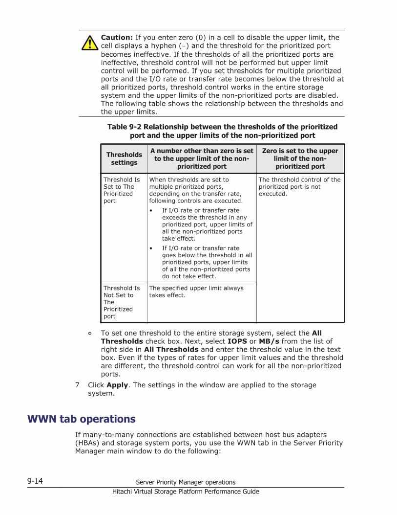
Caution: If you enter zero (0) in a cell to disable the upper limit, thecell displays a hyphen (-) and the threshold for the prioritized portbecomes ineffective. If the thresholds of all the prioritized ports areineffective, threshold control will not be performed but upper limitcontrol will be performed. If you set thresholds for multiple prioritizedports and the I/O rate or transfer rate becomes below the threshold atall prioritized ports, threshold control works in the entire storagesystem and the upper limits of the non-prioritized ports are disabled.The following table shows the relationship between the thresholds andthe upper limits.
Table 9-2 Relationship between the thresholds of the prioritizedport and the upper limits of the non-prioritized port
Thresholdssettings
A number other than zero is setto the upper limit of the non-
prioritized port
Zero is set to the upperlimit of the non-prioritized port
Threshold IsSet to ThePrioritizedport
When thresholds are set tomultiple prioritized ports,depending on the transfer rate,following controls are executed.• If I/O rate or transfer rate
exceeds the threshold in anyprioritized port, upper limits ofall the non-prioritized portstake effect.
• If I/O rate or transfer rategoes below the threshold in allprioritized ports, upper limitsof all the non-prioritized portsdo not take effect.
The threshold control of theprioritized port is notexecuted.
Threshold IsNot Set toThePrioritizedport
The specified upper limit alwaystakes effect.
¢ To set one threshold to the entire storage system, select the AllThresholds check box. Next, select IOPS or MB/s from the list ofright side in All Thresholds and enter the threshold value in the textbox. Even if the types of rates for upper limit values and the thresholdare different, the threshold control can work for all the non-prioritizedports.
7. Click Apply. The settings in the window are applied to the storagesystem.
WWN tab operationsIf many-to-many connections are established between host bus adapters(HBAs) and storage system ports, you use the WWN tab in the Server PriorityManager main window to do the following:
9-14 Server Priority Manager operationsHitachi Virtual Storage Platform Performance Guide
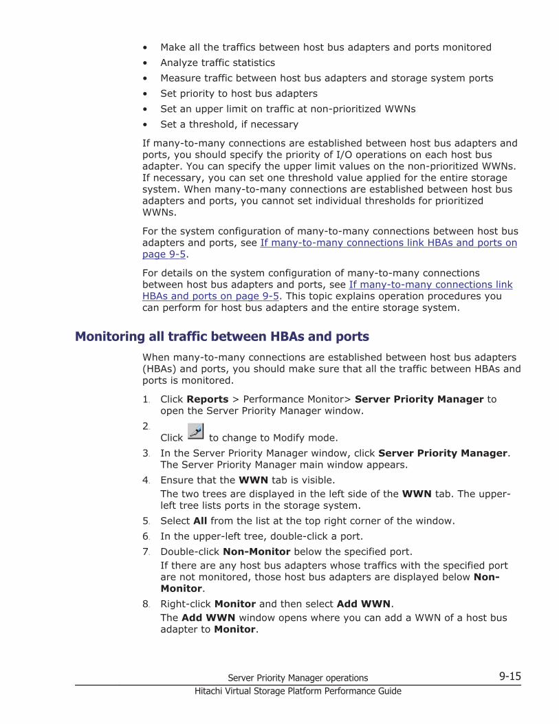
• Make all the traffics between host bus adapters and ports monitored• Analyze traffic statistics• Measure traffic between host bus adapters and storage system ports• Set priority to host bus adapters• Set an upper limit on traffic at non-prioritized WWNs• Set a threshold, if necessary
If many-to-many connections are established between host bus adapters andports, you should specify the priority of I/O operations on each host busadapter. You can specify the upper limit values on the non-prioritized WWNs.If necessary, you can set one threshold value applied for the entire storagesystem. When many-to-many connections are established between host busadapters and ports, you cannot set individual thresholds for prioritizedWWNs.
For the system configuration of many-to-many connections between host busadapters and ports, see If many-to-many connections link HBAs and ports onpage 9-5.
For details on the system configuration of many-to-many connectionsbetween host bus adapters and ports, see If many-to-many connections linkHBAs and ports on page 9-5. This topic explains operation procedures youcan perform for host bus adapters and the entire storage system.
Monitoring all traffic between HBAs and portsWhen many-to-many connections are established between host bus adapters(HBAs) and ports, you should make sure that all the traffic between HBAs andports is monitored.
1. Click Reports > Performance Monitor> Server Priority Manager toopen the Server Priority Manager window.
2.
Click to change to Modify mode.3. In the Server Priority Manager window, click Server Priority Manager.
The Server Priority Manager main window appears.4. Ensure that the WWN tab is visible.
The two trees are displayed in the left side of the WWN tab. The upper-left tree lists ports in the storage system.
5. Select All from the list at the top right corner of the window.6. In the upper-left tree, double-click a port.7. Double-click Non-Monitor below the specified port.
If there are any host bus adapters whose traffics with the specified portare not monitored, those host bus adapters are displayed below Non-Monitor.
8. Right-click Monitor and then select Add WWN.The Add WWN window opens where you can add a WWN of a host busadapter to Monitor.
Server Priority Manager operations 9-15Hitachi Virtual Storage Platform Performance Guide
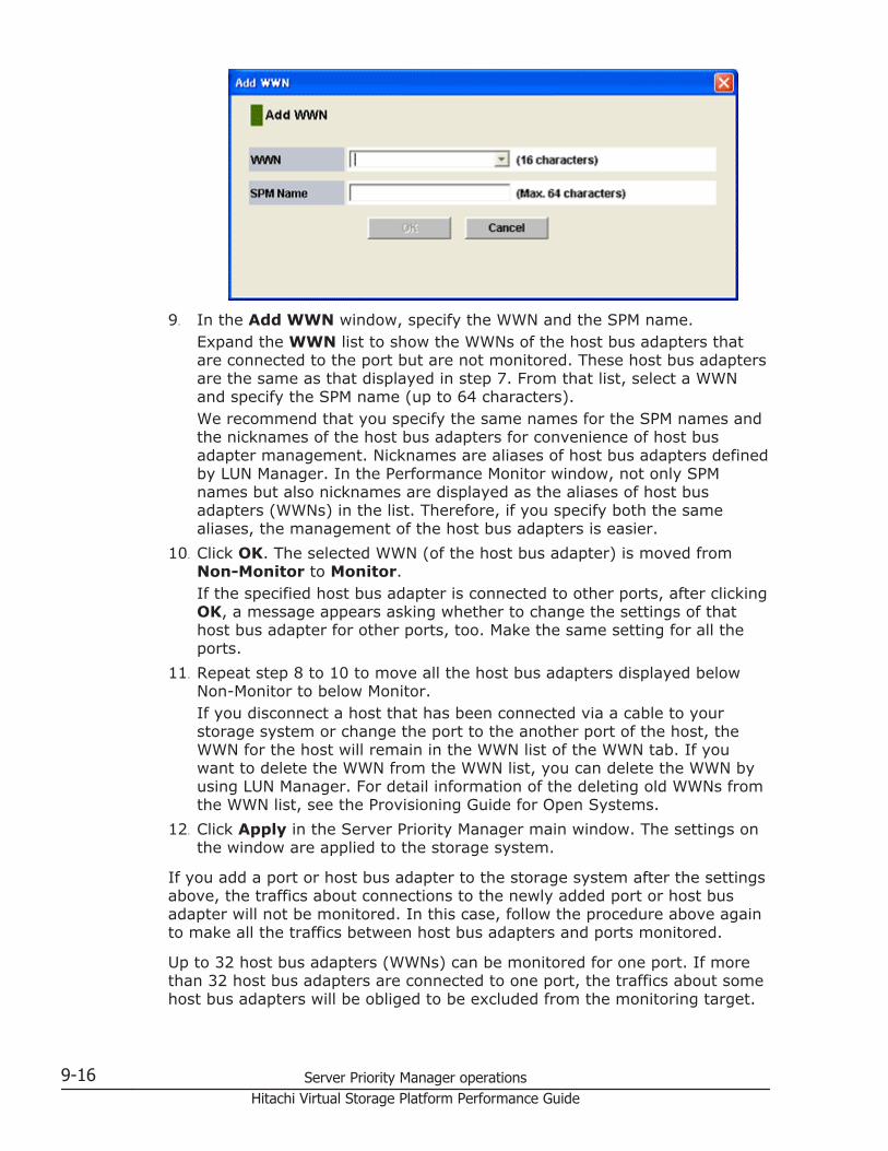
9. In the Add WWN window, specify the WWN and the SPM name.Expand the WWN list to show the WWNs of the host bus adapters thatare connected to the port but are not monitored. These host bus adaptersare the same as that displayed in step 7. From that list, select a WWNand specify the SPM name (up to 64 characters).We recommend that you specify the same names for the SPM names andthe nicknames of the host bus adapters for convenience of host busadapter management. Nicknames are aliases of host bus adapters definedby LUN Manager. In the Performance Monitor window, not only SPMnames but also nicknames are displayed as the aliases of host busadapters (WWNs) in the list. Therefore, if you specify both the samealiases, the management of the host bus adapters is easier.
10. Click OK. The selected WWN (of the host bus adapter) is moved fromNon-Monitor to Monitor.If the specified host bus adapter is connected to other ports, after clickingOK, a message appears asking whether to change the settings of thathost bus adapter for other ports, too. Make the same setting for all theports.
11. Repeat step 8 to 10 to move all the host bus adapters displayed belowNon-Monitor to below Monitor.If you disconnect a host that has been connected via a cable to yourstorage system or change the port to the another port of the host, theWWN for the host will remain in the WWN list of the WWN tab. If youwant to delete the WWN from the WWN list, you can delete the WWN byusing LUN Manager. For detail information of the deleting old WWNs fromthe WWN list, see the Provisioning Guide for Open Systems.
12. Click Apply in the Server Priority Manager main window. The settings onthe window are applied to the storage system.
If you add a port or host bus adapter to the storage system after the settingsabove, the traffics about connections to the newly added port or host busadapter will not be monitored. In this case, follow the procedure above againto make all the traffics between host bus adapters and ports monitored.
Up to 32 host bus adapters (WWNs) can be monitored for one port. If morethan 32 host bus adapters are connected to one port, the traffics about somehost bus adapters will be obliged to be excluded from the monitoring target.
9-16 Server Priority Manager operationsHitachi Virtual Storage Platform Performance Guide
Consider the intended use of each host and move the host bus adapterswhich you think not necessary to be monitored to Non-Monitor by thefollowing steps.
Excluding traffic between a host bus adapter and a port from the monitoringtarget
1. Click Reports > Performance Monitor> Server Priority Manager toopen the Server Priority Manager window.
2.
Click to change to Modify mode.3. In the Server Priority Manager window, click Server Priority Manager.
The Server Priority Manager main window appears.4. Ensure that the WWN tab is displayed.5. Select All from the list at the top right corner of the window.6. In the upper-left tree, double-click a port to which more than 32 host bus
adapters are connected.7. Double-click Monitor below the specified port.8. Right-click the WWN of a host bus adapter you want to exclude from the
monitoring target and then select Delete WWN from the pop-up menu.
Note:
• If the selected host bus adapter is connected to multiple ports, whenyou select the host bus adapter and select the Delete WWN pop-upmenu, a message will appear that asks you whether to move the hostbus adapter from Monitor to Non-Monitor below all other ports, too.
• If the selected host bus adapter is contained in an SPM group, amessage will appear that tell you to delete the host bus adapter fromthe SPM group on ahead. You cannot move a host bus adapter whichis contained in an SPM group from Monitor to Non-Monitor. For detailson how to delete a host bus adapter from an SPM group, see Deletingan HBA from an SPM group on page 9-25.
9. Click OK for the confirmation message that asks you whether to deletethe host bus adapter.The deleted host bus adapter (WWN) is moved from Monitor to Non-Monitor.
10. Click Apply in the Server Priority Manager main window.The settings on the window are applied to the storage system.
Analyzing traffic statisticsThe traffic statistics reveal the number of I/Os that have been made via portsfrom HBAs. They also reveal the amount of data that have been transferredbetween ports and HBAs. You must analyze the traffic statistics to determineupper limit values that should be applied to I/O rates or transfer rates forlow-priority HBAs.
Server Priority Manager operations 9-17Hitachi Virtual Storage Platform Performance Guide
The following is the procedure for using the Server Priority Manager mainwindow to analyze traffic statistics. You can also use the Performance Monitorwindow to analyze traffic statistics. Performance Monitor can display a linegraph that indicates changes in traffic.
1. Click Reports > Performance Monitor> Server Priority Manager toopen the Server Priority Manager window.
2.
Click to change to Modify mode.3. In the Server Priority Manager window, click Server Priority Manager.
The Server Priority Manager main window appears.4. Select the WWN tab.5. Select All from the list at the top right corner of the window.6. Do one of the following:
¢ To analyze I/O rates, select IOPS from the list at the upper leftcorner.
¢ To analyze transfer rates, select MB/s from the list at the upper leftcorner of the list.
7. Below the Storage System folder in the upper-left tree, click the icon ofthe port whose traffic statistics you want to collect.The list displays traffic statistics (I/O rates or transfer rates) about thehost bus adapters that connect to the selected port.The following two types of traffic are shown. The traffic has attributesincluding the average and maximum values.
¢ Traffic between the host bus adapter and the selected port (shown inPer Port)
¢ Sum of the traffic between the host bus adapter and all the portsconnected to the host bus adapter (shown in WWN Total)
Note: The traffic statistics only about the host bus adapters belowMonitor appear in the list.The WWN Total traffic statistics will also be displayed in the list whenyou click an icon in the lower left tree. If you click the Storage Systemfolder in the lower left tree, the sum of the traffic of the host busadapters registered on each SPM group is displayed. For details onSPM groups, see Grouping host bus adapters on page 9-24.
8. Analyze the information in the list and then determine upper limit valuesthat should be applied to non-prioritized WWNs. If necessary, determinethreshold values that should be applied to prioritized WWNs. For details,see If many-to-many connections link HBAs and ports on page 9-5.
Setting priority for host bus adaptersIf many-to-many connection is established between host bus adapters (HBAs)and ports, you need to define the priority of WWNs, measure traffic betweeneach HBA and the port that the HBA is connected to, and analyze the traffics.
9-18 Server Priority Manager operationsHitachi Virtual Storage Platform Performance Guide
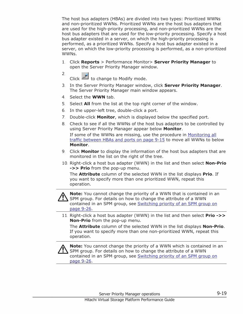
The host bus adapters (HBAs) are divided into two types: Prioritized WWNsand non-prioritized WWNs. Prioritized WWNs are the host bus adapters thatare used for the high-priority processing, and non-prioritized WWNs are thehost bus adapters that are used for the low-priority processing. Specify a hostbus adapter existed in a server, on which the high-priority processing isperformed, as a prioritized WWNs. Specify a host bus adapter existed in aserver, on which the low-priority processing is performed, as a non-prioritizedWWNs.
1. Click Reports > Performance Monitor> Server Priority Manager toopen the Server Priority Manager window.
2.
Click to change to Modify mode.3. In the Server Priority Manager window, click Server Priority Manager.
The Server Priority Manager main window appears.4. Select the WWN tab.5. Select All from the list at the top right corner of the window.6. In the upper-left tree, double-click a port.7. Double-click Monitor, which is displayed below the specified port.8. Check to see if all the WWNs of the host bus adapters to be controlled by
using Server Priority Manager appear below Monitor.If some of the WWNs are missing, use the procedure in Monitoring alltraffic between HBAs and ports on page 9-15 to move all WWNs to belowMonitor.
9. Click Monitor to display the information of the host bus adapters that aremonitored in the list on the right of the tree.
10. Right-click a host bus adapter (WWN) in the list and then select Non-Prio->> Prio from the pop-up menu.The Attribute column of the selected WWN in the list displays Prio. Ifyou want to specify more than one prioritized WWN, repeat thisoperation.
Note: You cannot change the priority of a WWN that is contained in anSPM group. For details on how to change the attribute of a WWNcontained in an SPM group, see Switching priority of an SPM group onpage 9-26.
11. Right-click a host bus adapter (WWN) in the list and then select Prio ->>Non-Prio from the pop-up menu.The Attribute column of the selected WWN in the list displays Non-Prio.If you want to specify more than one non-prioritized WWN, repeat thisoperation.
Note: You cannot change the priority of a WWN which is contained in anSPM group. For details on how to change the attribute of a WWNcontained in an SPM group, see Switching priority of an SPM group onpage 9-26.
Server Priority Manager operations 9-19Hitachi Virtual Storage Platform Performance Guide
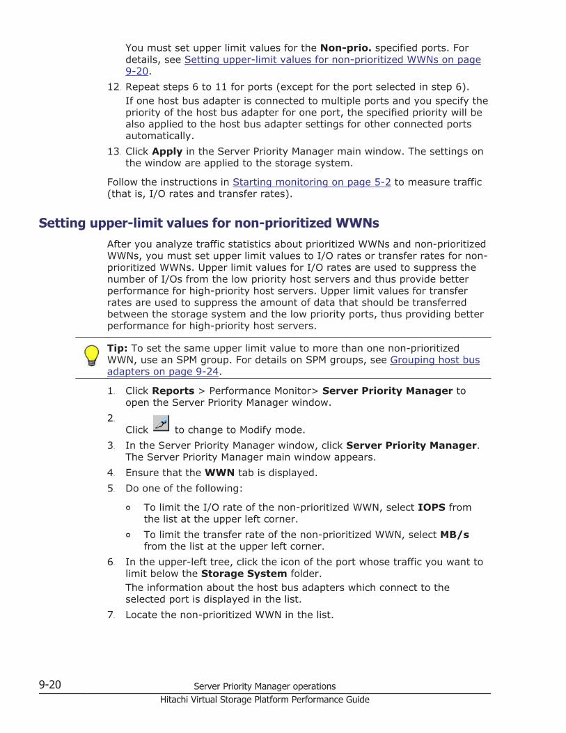
You must set upper limit values for the Non-prio. specified ports. Fordetails, see Setting upper-limit values for non-prioritized WWNs on page9-20.
12. Repeat steps 6 to 11 for ports (except for the port selected in step 6).If one host bus adapter is connected to multiple ports and you specify thepriority of the host bus adapter for one port, the specified priority will bealso applied to the host bus adapter settings for other connected portsautomatically.
13. Click Apply in the Server Priority Manager main window. The settings onthe window are applied to the storage system.
Follow the instructions in Starting monitoring on page 5-2 to measure traffic(that is, I/O rates and transfer rates).
Setting upper-limit values for non-prioritized WWNsAfter you analyze traffic statistics about prioritized WWNs and non-prioritizedWWNs, you must set upper limit values to I/O rates or transfer rates for non-prioritized WWNs. Upper limit values for I/O rates are used to suppress thenumber of I/Os from the low priority host servers and thus provide betterperformance for high-priority host servers. Upper limit values for transferrates are used to suppress the amount of data that should be transferredbetween the storage system and the low priority ports, thus providing betterperformance for high-priority host servers.
Tip: To set the same upper limit value to more than one non-prioritizedWWN, use an SPM group. For details on SPM groups, see Grouping host busadapters on page 9-24.
1. Click Reports > Performance Monitor> Server Priority Manager toopen the Server Priority Manager window.
2.
Click to change to Modify mode.3. In the Server Priority Manager window, click Server Priority Manager.
The Server Priority Manager main window appears.4. Ensure that the WWN tab is displayed.5. Do one of the following:
¢ To limit the I/O rate of the non-prioritized WWN, select IOPS fromthe list at the upper left corner.
¢ To limit the transfer rate of the non-prioritized WWN, select MB/sfrom the list at the upper left corner.
6. In the upper-left tree, click the icon of the port whose traffic you want tolimit below the Storage System folder.The information about the host bus adapters which connect to theselected port is displayed in the list.
7. Locate the non-prioritized WWN in the list.
9-20 Server Priority Manager operationsHitachi Virtual Storage Platform Performance Guide
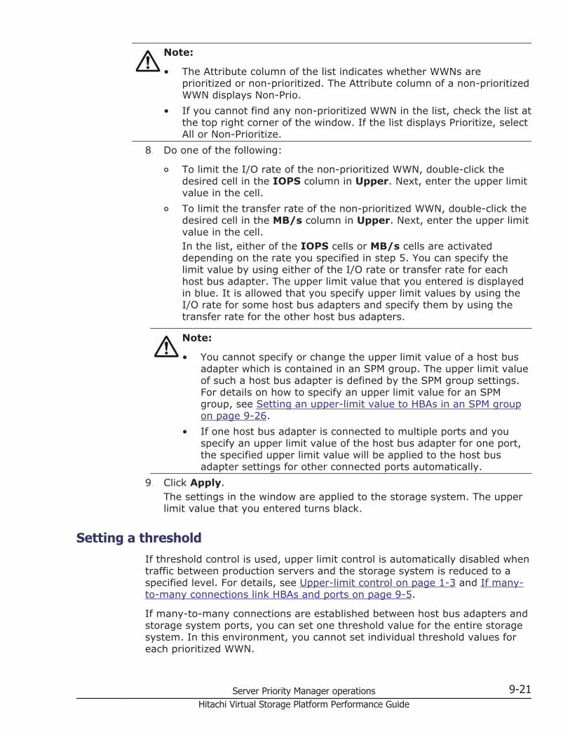
Note:
• The Attribute column of the list indicates whether WWNs areprioritized or non-prioritized. The Attribute column of a non-prioritizedWWN displays Non-Prio.
• If you cannot find any non-prioritized WWN in the list, check the list atthe top right corner of the window. If the list displays Prioritize, selectAll or Non-Prioritize.
8. Do one of the following:
¢ To limit the I/O rate of the non-prioritized WWN, double-click thedesired cell in the IOPS column in Upper. Next, enter the upper limitvalue in the cell.
¢ To limit the transfer rate of the non-prioritized WWN, double-click thedesired cell in the MB/s column in Upper. Next, enter the upper limitvalue in the cell.In the list, either of the IOPS cells or MB/s cells are activateddepending on the rate you specified in step 5. You can specify thelimit value by using either of the I/O rate or transfer rate for eachhost bus adapter. The upper limit value that you entered is displayedin blue. It is allowed that you specify upper limit values by using theI/O rate for some host bus adapters and specify them by using thetransfer rate for the other host bus adapters.
Note:
• You cannot specify or change the upper limit value of a host busadapter which is contained in an SPM group. The upper limit valueof such a host bus adapter is defined by the SPM group settings.For details on how to specify an upper limit value for an SPMgroup, see Setting an upper-limit value to HBAs in an SPM groupon page 9-26.
• If one host bus adapter is connected to multiple ports and youspecify an upper limit value of the host bus adapter for one port,the specified upper limit value will be applied to the host busadapter settings for other connected ports automatically.
9. Click Apply.The settings in the window are applied to the storage system. The upperlimit value that you entered turns black.
Setting a thresholdIf threshold control is used, upper limit control is automatically disabled whentraffic between production servers and the storage system is reduced to aspecified level. For details, see Upper-limit control on page 1-3 and If many-to-many connections link HBAs and ports on page 9-5.
If many-to-many connections are established between host bus adapters andstorage system ports, you can set one threshold value for the entire storagesystem. In this environment, you cannot set individual threshold values foreach prioritized WWN.
Server Priority Manager operations 9-21Hitachi Virtual Storage Platform Performance Guide
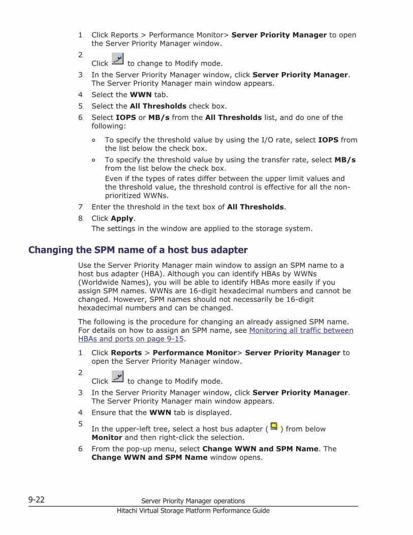
1. Click Reports > Performance Monitor> Server Priority Manager to openthe Server Priority Manager window.
2.
Click to change to Modify mode.3. In the Server Priority Manager window, click Server Priority Manager.
The Server Priority Manager main window appears.4. Select the WWN tab.5. Select the All Thresholds check box.6. Select IOPS or MB/s from the All Thresholds list, and do one of the
following:
¢ To specify the threshold value by using the I/O rate, select IOPS fromthe list below the check box.
¢ To specify the threshold value by using the transfer rate, select MB/sfrom the list below the check box.Even if the types of rates differ between the upper limit values andthe threshold value, the threshold control is effective for all the non-prioritized WWNs.
7. Enter the threshold in the text box of All Thresholds.8. Click Apply.
The settings in the window are applied to the storage system.
Changing the SPM name of a host bus adapterUse the Server Priority Manager main window to assign an SPM name to ahost bus adapter (HBA). Although you can identify HBAs by WWNs(Worldwide Names), you will be able to identify HBAs more easily if youassign SPM names. WWNs are 16-digit hexadecimal numbers and cannot bechanged. However, SPM names should not necessarily be 16-digithexadecimal numbers and can be changed.
The following is the procedure for changing an already assigned SPM name.For details on how to assign an SPM name, see Monitoring all traffic betweenHBAs and ports on page 9-15.
1. Click Reports > Performance Monitor> Server Priority Manager toopen the Server Priority Manager window.
2.
Click to change to Modify mode.3. In the Server Priority Manager window, click Server Priority Manager.
The Server Priority Manager main window appears.4. Ensure that the WWN tab is displayed.5.
In the upper-left tree, select a host bus adapter ( ) from belowMonitor and then right-click the selection.
6. From the pop-up menu, select Change WWN and SPM Name. TheChange WWN and SPM Name window opens.
9-22 Server Priority Manager operationsHitachi Virtual Storage Platform Performance Guide
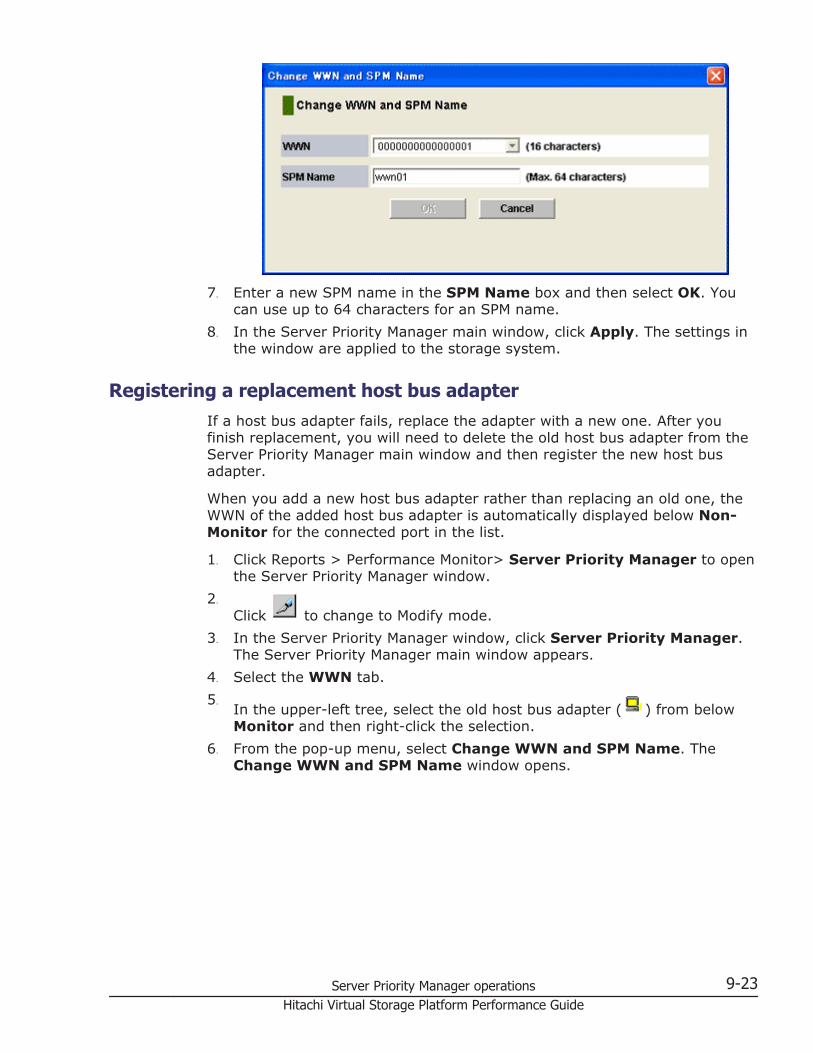
7. Enter a new SPM name in the SPM Name box and then select OK. Youcan use up to 64 characters for an SPM name.
8. In the Server Priority Manager main window, click Apply. The settings inthe window are applied to the storage system.
Registering a replacement host bus adapterIf a host bus adapter fails, replace the adapter with a new one. After youfinish replacement, you will need to delete the old host bus adapter from theServer Priority Manager main window and then register the new host busadapter.
When you add a new host bus adapter rather than replacing an old one, theWWN of the added host bus adapter is automatically displayed below Non-Monitor for the connected port in the list.
1. Click Reports > Performance Monitor> Server Priority Manager to openthe Server Priority Manager window.
2.
Click to change to Modify mode.3. In the Server Priority Manager window, click Server Priority Manager.
The Server Priority Manager main window appears.4. Select the WWN tab.5.
In the upper-left tree, select the old host bus adapter ( ) from belowMonitor and then right-click the selection.
6. From the pop-up menu, select Change WWN and SPM Name. TheChange WWN and SPM Name window opens.
Server Priority Manager operations 9-23Hitachi Virtual Storage Platform Performance Guide
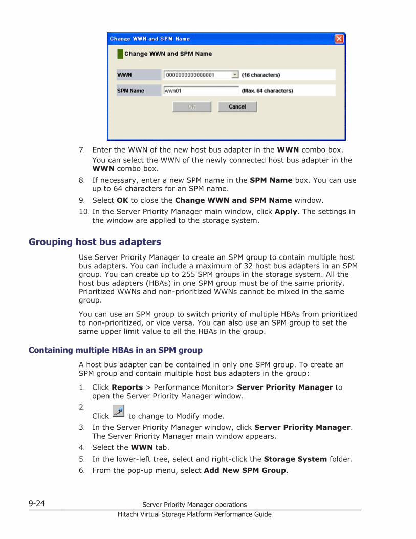
7. Enter the WWN of the new host bus adapter in the WWN combo box.You can select the WWN of the newly connected host bus adapter in theWWN combo box.
8. If necessary, enter a new SPM name in the SPM Name box. You can useup to 64 characters for an SPM name.
9. Select OK to close the Change WWN and SPM Name window.10. In the Server Priority Manager main window, click Apply. The settings in
the window are applied to the storage system.
Grouping host bus adaptersUse Server Priority Manager to create an SPM group to contain multiple hostbus adapters. You can include a maximum of 32 host bus adapters in an SPMgroup. You can create up to 255 SPM groups in the storage system. All thehost bus adapters (HBAs) in one SPM group must be of the same priority.Prioritized WWNs and non-prioritized WWNs cannot be mixed in the samegroup.
You can use an SPM group to switch priority of multiple HBAs from prioritizedto non-prioritized, or vice versa. You can also use an SPM group to set thesame upper limit value to all the HBAs in the group.
Containing multiple HBAs in an SPM group
A host bus adapter can be contained in only one SPM group. To create anSPM group and contain multiple host bus adapters in the group:
1. Click Reports > Performance Monitor> Server Priority Manager toopen the Server Priority Manager window.
2.
Click to change to Modify mode.3. In the Server Priority Manager window, click Server Priority Manager.
The Server Priority Manager main window appears.4. Select the WWN tab.5. In the lower-left tree, select and right-click the Storage System folder.6. From the pop-up menu, select Add New SPM Group.
9-24 Server Priority Manager operationsHitachi Virtual Storage Platform Performance Guide
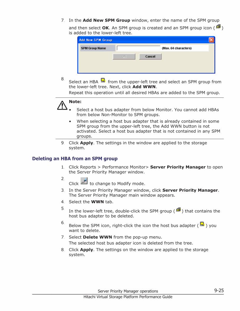
7. In the Add New SPM Group window, enter the name of the SPM group
and then select OK. An SPM group is created and an SPM group icon ( )is added to the lower-left tree.
8.Select an HBA from the upper-left tree and select an SPM group fromthe lower-left tree. Next, click Add WWN.Repeat this operation until all desired HBAs are added to the SPM group.
Note:
• Select a host bus adapter from below Monitor. You cannot add HBAsfrom below Non-Monitor to SPM groups.
• When selecting a host bus adapter that is already contained in someSPM group from the upper-left tree, the Add WWN button is notactivated. Select a host bus adapter that is not contained in any SPMgroups.
9. Click Apply. The settings in the window are applied to the storagesystem.
Deleting an HBA from an SPM group
1. Click Reports > Performance Monitor> Server Priority Manager to openthe Server Priority Manager window.
2.
Click to change to Modify mode.3. In the Server Priority Manager window, click Server Priority Manager.
The Server Priority Manager main window appears.4. Select the WWN tab.5. In the lower-left tree, double-click the SPM group ( ) that contains the
host bus adapter to be deleted.6.
Below the SPM icon, right-click the icon the host bus adapter ( ) youwant to delete.
7. Select Delete WWN from the pop-up menu.The selected host bus adapter icon is deleted from the tree.
8. Click Apply. The settings on the window are applied to the storagesystem.
Server Priority Manager operations 9-25Hitachi Virtual Storage Platform Performance Guide
Switching priority of an SPM group
All the host bus adapters (HBAs) in one SPM group must be of the samepriority. Prioritized WWNs and non-prioritized WWNs cannot be mixed in oneSPM group.
You can use an SPM group to switch priority of multiple HBAs from prioritizedto non-prioritized, or vice versa.
1. Click Reports > Performance Monitor> Server Priority Manager toopen the Server Priority Manager window.
2.
Click to change to Modify mode.3. In the Server Priority Manager window, click Server Priority Manager.
The Server Priority Manager main window appears.4. Select the WWN tab.5. In the lower-left tree, select and right-click an SPM group ( ).6. Do one of the following:
¢ To switch priority from prioritized to non-prioritized, select Prio ->>Non-Prio from the pop-up menu.
¢ To switch priority from non-prioritized to prioritized, select Non-Prio ->> Prio from the pop-up menu.
7. Click Apply. The settings in the window are applied to the storagesystem.
Setting an upper-limit value to HBAs in an SPM group
If all the host bus adapters in an SPM group are non-prioritized WWNs, youcan set an upper limit value to HBA performance (i.e., I/O rate or transferrate). You can assign one upper limit value for one SPM group.
For example, suppose that the upper limit value 100 IOPS is assigned to anSPM group consisting of four host bus adapters. If the sum of the I/O rate ofthe four HBAs reaches 100 IOPS, Server Priority Manager controls the systemso that the sum of the I/O rates will not exceed 100 IOPS.
1. Click Reports > Performance Monitor> Server Priority Manager toopen the Server Priority Manager window.
2.
Click to change to Modify mode.3. In the Server Priority Manager window, click Server Priority Manager.
The Server Priority Manager main window appears.4. Select the WWN tab.5. In the lower-left tree, select and right-click the Storage System folder or
an SPM group ( ).6. If you selected the Storage System folder, take the following steps:
9-26 Server Priority Manager operationsHitachi Virtual Storage Platform Performance Guide
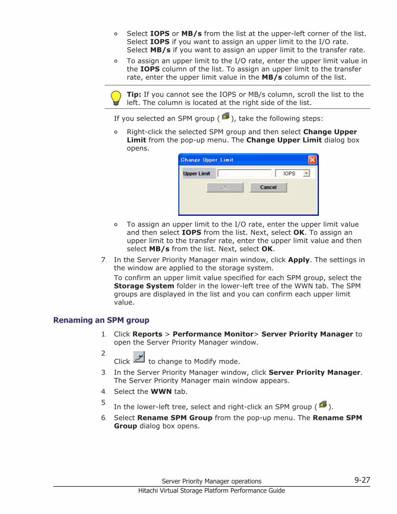
¢ Select IOPS or MB/s from the list at the upper-left corner of the list.Select IOPS if you want to assign an upper limit to the I/O rate.Select MB/s if you want to assign an upper limit to the transfer rate.
¢ To assign an upper limit to the I/O rate, enter the upper limit value inthe IOPS column of the list. To assign an upper limit to the transferrate, enter the upper limit value in the MB/s column of the list.
Tip: If you cannot see the IOPS or MB/s column, scroll the list to theleft. The column is located at the right side of the list.
If you selected an SPM group ( ), take the following steps:
¢ Right-click the selected SPM group and then select Change UpperLimit from the pop-up menu. The Change Upper Limit dialog boxopens.
¢ To assign an upper limit to the I/O rate, enter the upper limit valueand then select IOPS from the list. Next, select OK. To assign anupper limit to the transfer rate, enter the upper limit value and thenselect MB/s from the list. Next, select OK.
7. In the Server Priority Manager main window, click Apply. The settings inthe window are applied to the storage system.To confirm an upper limit value specified for each SPM group, select theStorage System folder in the lower-left tree of the WWN tab. The SPMgroups are displayed in the list and you can confirm each upper limitvalue.
Renaming an SPM group
1. Click Reports > Performance Monitor> Server Priority Manager toopen the Server Priority Manager window.
2.
Click to change to Modify mode.3. In the Server Priority Manager window, click Server Priority Manager.
The Server Priority Manager main window appears.4. Select the WWN tab.5. In the lower-left tree, select and right-click an SPM group ( ).6. Select Rename SPM Group from the pop-up menu. The Rename SPM
Group dialog box opens.
Server Priority Manager operations 9-27Hitachi Virtual Storage Platform Performance Guide
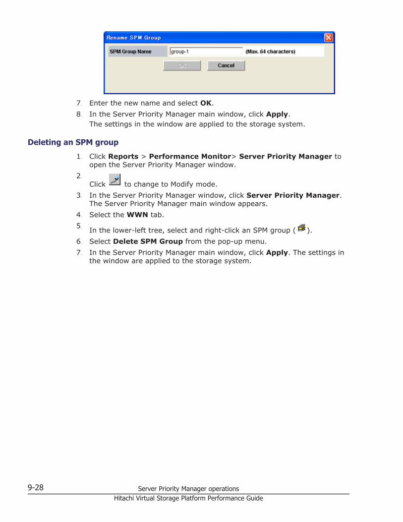
7. Enter the new name and select OK.8. In the Server Priority Manager main window, click Apply.
The settings in the window are applied to the storage system.
Deleting an SPM group
1. Click Reports > Performance Monitor> Server Priority Manager toopen the Server Priority Manager window.
2.
Click to change to Modify mode.3. In the Server Priority Manager window, click Server Priority Manager.
The Server Priority Manager main window appears.4. Select the WWN tab.5. In the lower-left tree, select and right-click an SPM group ( ).6. Select Delete SPM Group from the pop-up menu.7. In the Server Priority Manager main window, click Apply. The settings in
the window are applied to the storage system.
9-28 Server Priority Manager operationsHitachi Virtual Storage Platform Performance Guide
10Creating virtual cache partitions
Partitioning cache with Hitachi Virtual Partition Manager allows you to matchdata to appropriate storage resources based on availability, performance,capacity, and cost. It improves flexibility by allowing dynamic changes tocache partitions while in use.
□ Cache Logical Partition definition
□ Purpose of Cache Logical Partitions
□ Best practices for cache partition planning
□ Cache Logical Partition workflow
□ Calculating cache capacity
□ Adjusting the cache capacity of a CLPR
□ Creating a CLPR
□ Migrating resources to and from a CLPR
□ Deleting a CLPR
□ Troubleshooting Virtual Partition Manager
Creating virtual cache partitions 10-1Hitachi Virtual Storage Platform Performance Guide
Cache Logical Partition definitionA cache logical partition (CLPR) is a pool of the cache and parity groups in thestorage system. Partitioning cache into one or more CLPRs allows storageadministrators to dedicate individual CLPRs to a different host, preventing I/Ocontention for cache memory.
Purpose of Cache Logical PartitionsIf one storage system is shared with multiple hosts, one host reading orwriting a large amount of data can require enough of the storage systemcache memory to affect other users. Hitachi Virtual Partition Manager allowsimproved I/O performance by dividing storage system cache memory intomultiple CLPRs.
Partitioning cache dedicates cache resources for exclusive use by specificapplications to maintain priority and quality of service for business-criticalapplications. Storage administrators can secure and/or restrict access tostorage resources to ensure confidentiality for specific applications. Bydedicating resources to each partition as needed, a high quality of service canbe maintained for all users.
Corporate use exampleThe next figure shows three branch offices and a total of 128 GB of cachememory partitioned into one 40 GB segment for each office. The host forbranch A has a heavy I/O load. Because the cache memory is partitioned,that heavy I/O load cannot affect the cache memory for the other twobranches.
10-2 Creating virtual cache partitionsHitachi Virtual Storage Platform Performance Guide
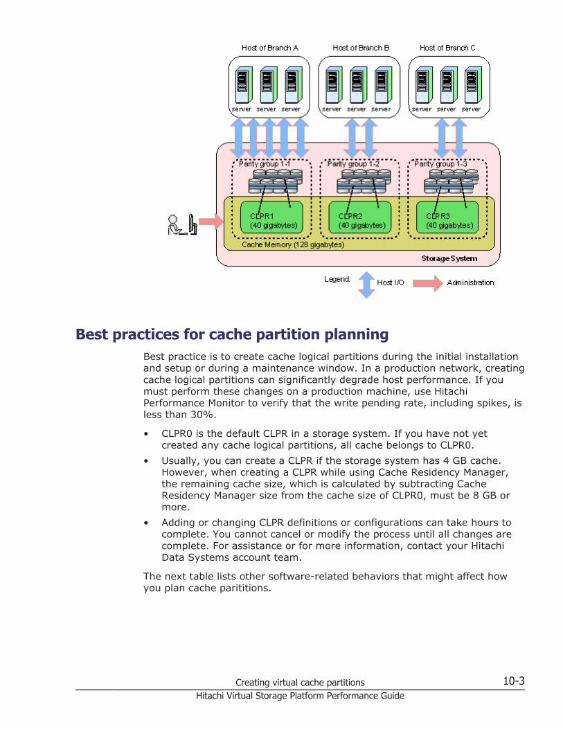
Best practices for cache partition planningBest practice is to create cache logical partitions during the initial installationand setup or during a maintenance window. In a production network, creatingcache logical partitions can significantly degrade host performance. If youmust perform these changes on a production machine, use HitachiPerformance Monitor to verify that the write pending rate, including spikes, isless than 30%.
• CLPR0 is the default CLPR in a storage system. If you have not yetcreated any cache logical partitions, all cache belongs to CLPR0.
• Usually, you can create a CLPR if the storage system has 4 GB cache.However, when creating a CLPR while using Cache Residency Manager,the remaining cache size, which is calculated by subtracting CacheResidency Manager size from the cache size of CLPR0, must be 8 GB ormore.
• Adding or changing CLPR definitions or configurations can take hours tocomplete. You cannot cancel or modify the process until all changes arecomplete. For assistance or for more information, contact your HitachiData Systems account team.
The next table lists other software-related behaviors that might affect howyou plan cache parititions.
Creating virtual cache partitions 10-3Hitachi Virtual Storage Platform Performance Guide
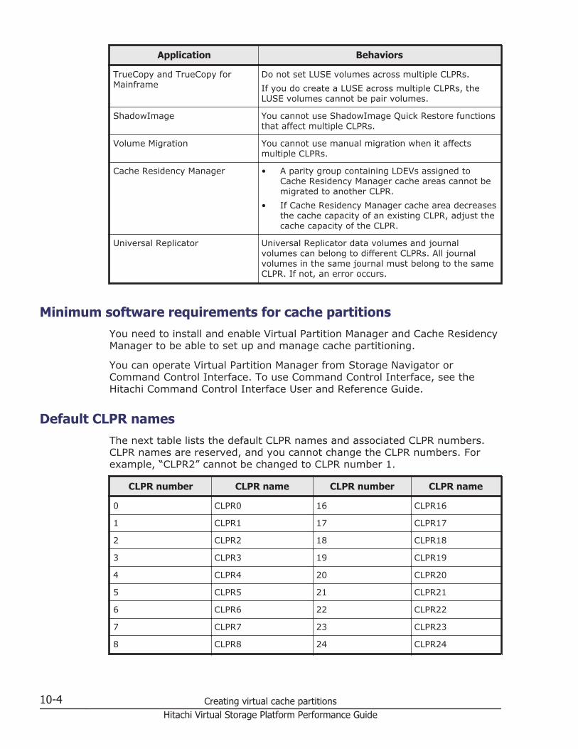
Application Behaviors
TrueCopy and TrueCopy forMainframe
Do not set LUSE volumes across multiple CLPRs.If you do create a LUSE across multiple CLPRs, theLUSE volumes cannot be pair volumes.
ShadowImage You cannot use ShadowImage Quick Restore functionsthat affect multiple CLPRs.
Volume Migration You cannot use manual migration when it affectsmultiple CLPRs.
Cache Residency Manager • A parity group containing LDEVs assigned toCache Residency Manager cache areas cannot bemigrated to another CLPR.
• If Cache Residency Manager cache area decreasesthe cache capacity of an existing CLPR, adjust thecache capacity of the CLPR.
Universal Replicator Universal Replicator data volumes and journalvolumes can belong to different CLPRs. All journalvolumes in the same journal must belong to the sameCLPR. If not, an error occurs.
Minimum software requirements for cache partitionsYou need to install and enable Virtual Partition Manager and Cache ResidencyManager to be able to set up and manage cache partitioning.
You can operate Virtual Partition Manager from Storage Navigator orCommand Control Interface. To use Command Control Interface, see theHitachi Command Control Interface User and Reference Guide.
Default CLPR namesThe next table lists the default CLPR names and associated CLPR numbers.CLPR names are reserved, and you cannot change the CLPR numbers. Forexample, “CLPR2” cannot be changed to CLPR number 1.
CLPR number CLPR name CLPR number CLPR name
0 CLPR0 16 CLPR16
1 CLPR1 17 CLPR17
2 CLPR2 18 CLPR18
3 CLPR3 19 CLPR19
4 CLPR4 20 CLPR20
5 CLPR5 21 CLPR21
6 CLPR6 22 CLPR22
7 CLPR7 23 CLPR23
8 CLPR8 24 CLPR24
10-4 Creating virtual cache partitionsHitachi Virtual Storage Platform Performance Guide
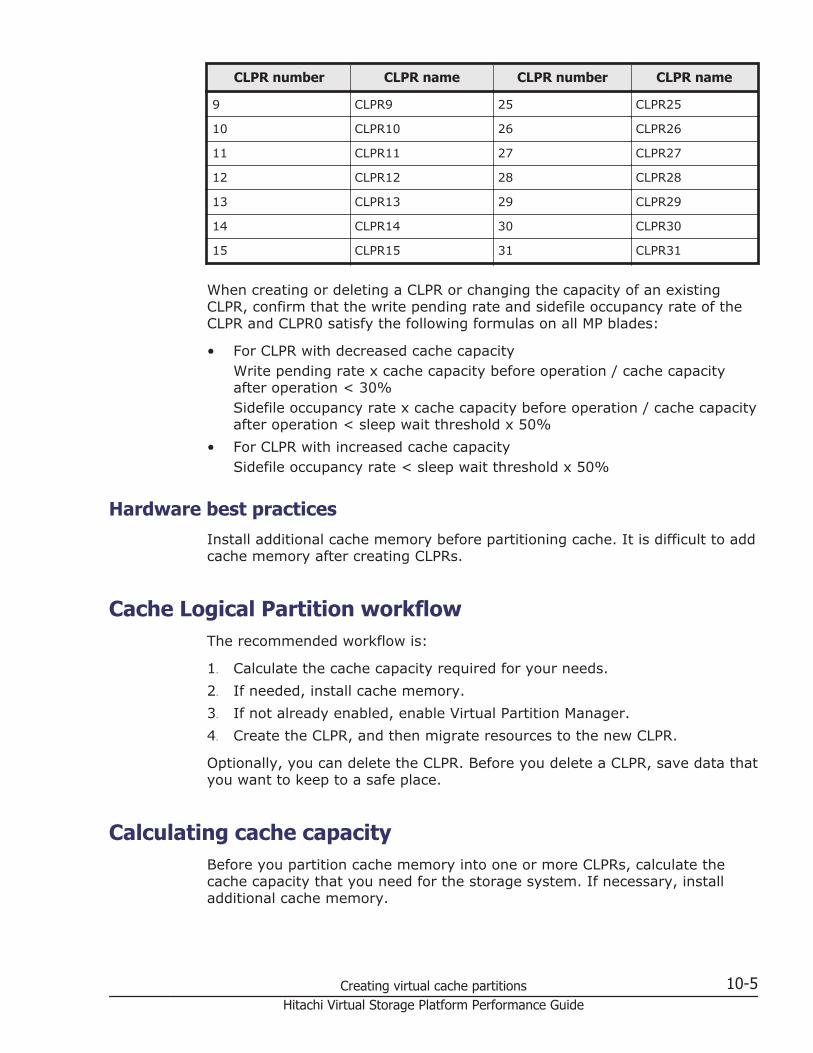
CLPR number CLPR name CLPR number CLPR name
9 CLPR9 25 CLPR25
10 CLPR10 26 CLPR26
11 CLPR11 27 CLPR27
12 CLPR12 28 CLPR28
13 CLPR13 29 CLPR29
14 CLPR14 30 CLPR30
15 CLPR15 31 CLPR31
When creating or deleting a CLPR or changing the capacity of an existingCLPR, confirm that the write pending rate and sidefile occupancy rate of theCLPR and CLPR0 satisfy the following formulas on all MP blades:
• For CLPR with decreased cache capacityWrite pending rate x cache capacity before operation / cache capacityafter operation < 30%Sidefile occupancy rate x cache capacity before operation / cache capacityafter operation < sleep wait threshold x 50%
• For CLPR with increased cache capacitySidefile occupancy rate < sleep wait threshold x 50%
Hardware best practicesInstall additional cache memory before partitioning cache. It is difficult to addcache memory after creating CLPRs.
Cache Logical Partition workflowThe recommended workflow is:
1. Calculate the cache capacity required for your needs.2. If needed, install cache memory.3. If not already enabled, enable Virtual Partition Manager.4. Create the CLPR, and then migrate resources to the new CLPR.
Optionally, you can delete the CLPR. Before you delete a CLPR, save data thatyou want to keep to a safe place.
Calculating cache capacityBefore you partition cache memory into one or more CLPRs, calculate thecache capacity that you need for the storage system. If necessary, installadditional cache memory.
Creating virtual cache partitions 10-5Hitachi Virtual Storage Platform Performance Guide
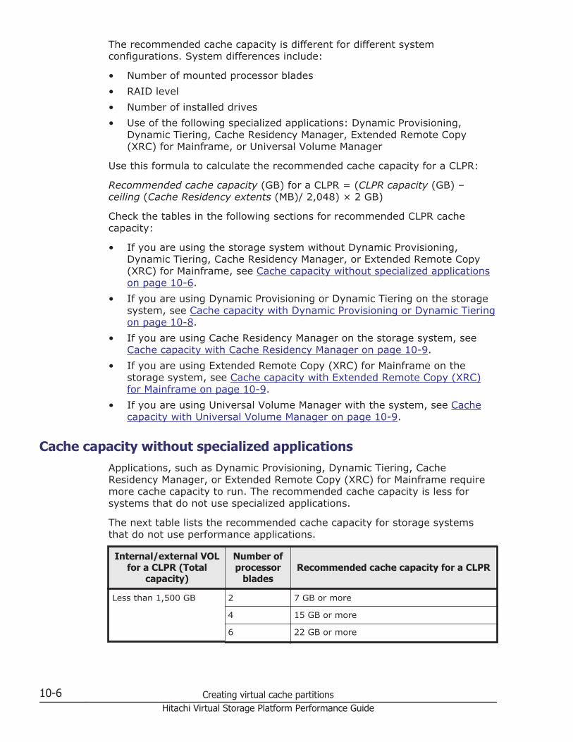
The recommended cache capacity is different for different systemconfigurations. System differences include:
• Number of mounted processor blades• RAID level• Number of installed drives• Use of the following specialized applications: Dynamic Provisioning,
Dynamic Tiering, Cache Residency Manager, Extended Remote Copy(XRC) for Mainframe, or Universal Volume Manager
Use this formula to calculate the recommended cache capacity for a CLPR:
Recommended cache capacity (GB) for a CLPR = (CLPR capacity (GB) –ceiling (Cache Residency extents (MB)/ 2,048) × 2 GB)
Check the tables in the following sections for recommended CLPR cachecapacity:
• If you are using the storage system without Dynamic Provisioning,Dynamic Tiering, Cache Residency Manager, or Extended Remote Copy(XRC) for Mainframe, see Cache capacity without specialized applicationson page 10-6.
• If you are using Dynamic Provisioning or Dynamic Tiering on the storagesystem, see Cache capacity with Dynamic Provisioning or Dynamic Tieringon page 10-8.
• If you are using Cache Residency Manager on the storage system, seeCache capacity with Cache Residency Manager on page 10-9.
• If you are using Extended Remote Copy (XRC) for Mainframe on thestorage system, see Cache capacity with Extended Remote Copy (XRC)for Mainframe on page 10-9.
• If you are using Universal Volume Manager with the system, see Cachecapacity with Universal Volume Manager on page 10-9.
Cache capacity without specialized applicationsApplications, such as Dynamic Provisioning, Dynamic Tiering, CacheResidency Manager, or Extended Remote Copy (XRC) for Mainframe requiremore cache capacity to run. The recommended cache capacity is less forsystems that do not use specialized applications.
The next table lists the recommended cache capacity for storage systemsthat do not use performance applications.
Internal/external VOLfor a CLPR (Total
capacity)
Number ofprocessor
bladesRecommended cache capacity for a CLPR
Less than 1,500 GB 2 7 GB or more
4 15 GB or more
6 22 GB or more
10-6 Creating virtual cache partitionsHitachi Virtual Storage Platform Performance Guide
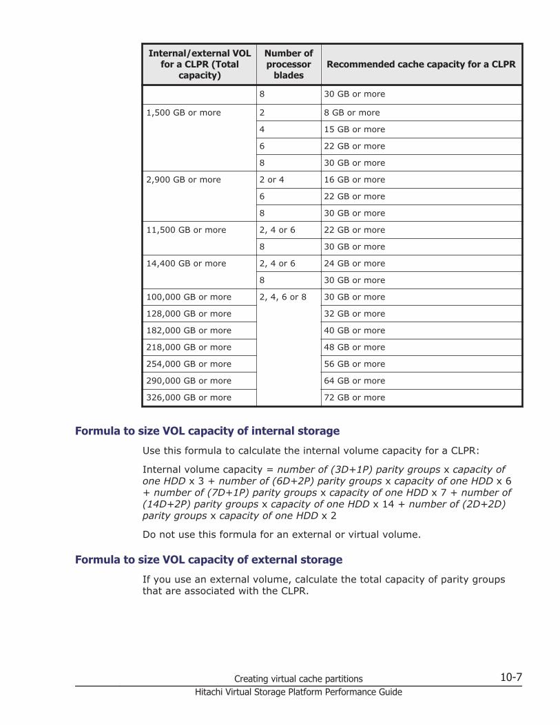
Internal/external VOLfor a CLPR (Total
capacity)
Number ofprocessor
bladesRecommended cache capacity for a CLPR
8 30 GB or more
1,500 GB or more 2 8 GB or more
4 15 GB or more
6 22 GB or more
8 30 GB or more
2,900 GB or more 2 or 4 16 GB or more
6 22 GB or more
8 30 GB or more
11,500 GB or more 2, 4 or 6 22 GB or more
8 30 GB or more
14,400 GB or more 2, 4 or 6 24 GB or more
8 30 GB or more
100,000 GB or more 2, 4, 6 or 8 30 GB or more
128,000 GB or more 32 GB or more
182,000 GB or more 40 GB or more
218,000 GB or more 48 GB or more
254,000 GB or more 56 GB or more
290,000 GB or more 64 GB or more
326,000 GB or more 72 GB or more
Formula to size VOL capacity of internal storage
Use this formula to calculate the internal volume capacity for a CLPR:
Internal volume capacity = number of (3D+1P) parity groups x capacity ofone HDD x 3 + number of (6D+2P) parity groups x capacity of one HDD x 6+ number of (7D+1P) parity groups x capacity of one HDD x 7 + number of(14D+2P) parity groups x capacity of one HDD x 14 + number of (2D+2D)parity groups x capacity of one HDD x 2
Do not use this formula for an external or virtual volume.
Formula to size VOL capacity of external storage
If you use an external volume, calculate the total capacity of parity groupsthat are associated with the CLPR.
Creating virtual cache partitions 10-7Hitachi Virtual Storage Platform Performance Guide
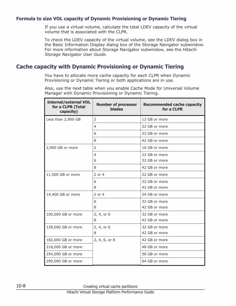
Formula to size VOL capacity of Dynamic Provisioning or Dynamic Tiering
If you use a virtual volume, calculate the total LDEV capacity of the virtualvolume that is associated with the CLPR.
To check the LDEV capacity of the virtual volume, see the LDEV dialog box inthe Basic Information Display dialog box of the Storage Navigator subwindow.For more information about Storage Navigator subwindow, see the HitachiStorage Navigator User Guide.
Cache capacity with Dynamic Provisioning or Dynamic TieringYou have to allocate more cache capacity for each CLPR when DynamicProvisioning or Dynamic Tiering or both applications are in use.
Also, use the next table when you enable Cache Mode for Universal VolumeManager with Dynamic Provisioning or Dynamic Tiering.
Internal/external VOLfor a CLPR (Total
capacity)
Number of processorblades
Recommended cache capacityfor a CLPR
Less than 2,900 GB 2 12 GB or more
4 22 GB or more
6 22 GB or more
8 42 GB or more
2,900 GB or more 2 16 GB or more
46
22 GB or more32 GB or more
8 42 GB or more
11,500 GB or more 2 or 4 22 GB or more
68
32 GB or more42 GB or more
14,400 GB or more 2 or 4 24 GB or more
68
32 GB or more42 GB or more
100,000 GB or more 2, 4, or 68
32 GB or more42 GB or more
128,000 GB or more 2, 4, or 68
32 GB or more42 GB or more
182,000 GB or more 2, 4, 6, or 8 42 GB or more
218,000 GB or more 48 GB or more
254,000 GB or more 56 GB or more
290,000 GB or more 64 GB or more
10-8 Creating virtual cache partitionsHitachi Virtual Storage Platform Performance Guide
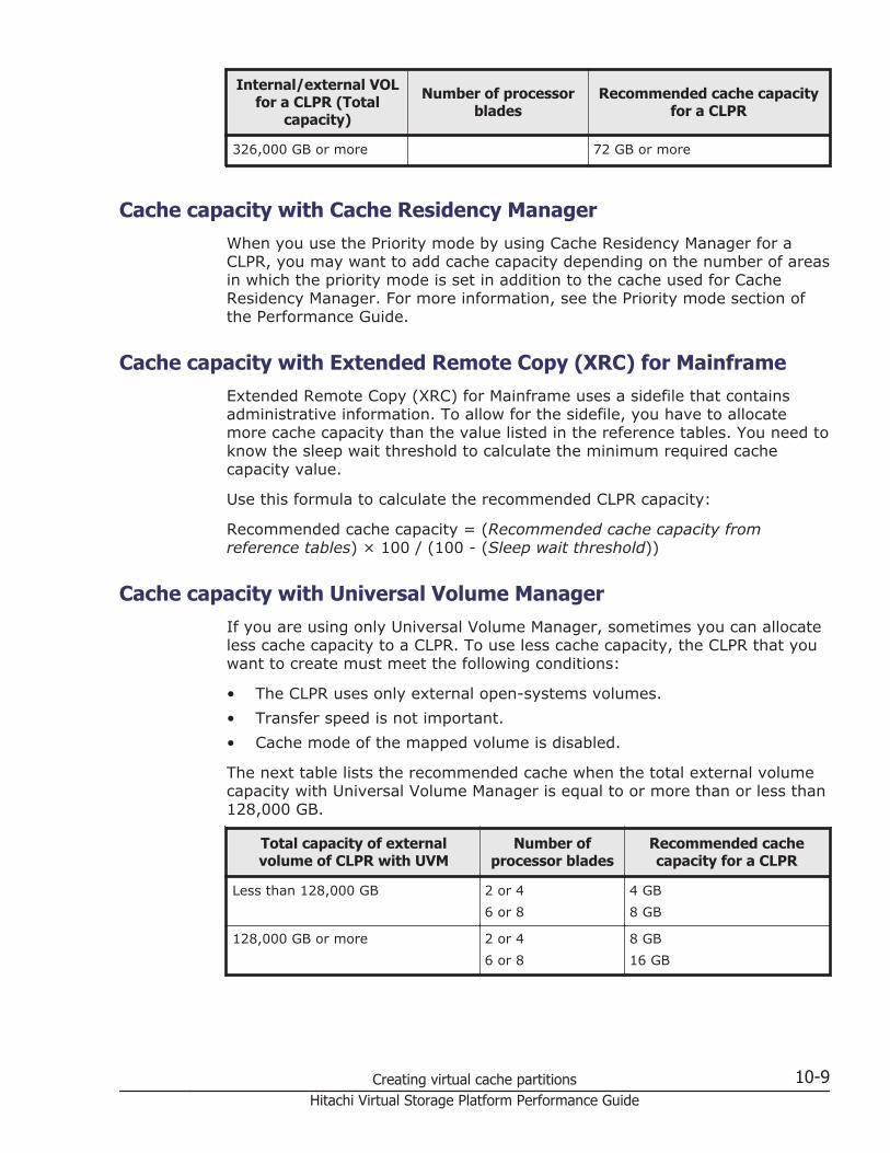
Internal/external VOLfor a CLPR (Total
capacity)
Number of processorblades
Recommended cache capacityfor a CLPR
326,000 GB or more 72 GB or more
Cache capacity with Cache Residency ManagerWhen you use the Priority mode by using Cache Residency Manager for aCLPR, you may want to add cache capacity depending on the number of areasin which the priority mode is set in addition to the cache used for CacheResidency Manager. For more information, see the Priority mode section ofthe Performance Guide.
Cache capacity with Extended Remote Copy (XRC) for MainframeExtended Remote Copy (XRC) for Mainframe uses a sidefile that containsadministrative information. To allow for the sidefile, you have to allocatemore cache capacity than the value listed in the reference tables. You need toknow the sleep wait threshold to calculate the minimum required cachecapacity value.
Use this formula to calculate the recommended CLPR capacity:
Recommended cache capacity = (Recommended cache capacity fromreference tables) × 100 / (100 - (Sleep wait threshold))
Cache capacity with Universal Volume ManagerIf you are using only Universal Volume Manager, sometimes you can allocateless cache capacity to a CLPR. To use less cache capacity, the CLPR that youwant to create must meet the following conditions:
• The CLPR uses only external open-systems volumes.• Transfer speed is not important.• Cache mode of the mapped volume is disabled.
The next table lists the recommended cache when the total external volumecapacity with Universal Volume Manager is equal to or more than or less than128,000 GB.
Total capacity of externalvolume of CLPR with UVM
Number ofprocessor blades
Recommended cachecapacity for a CLPR
Less than 128,000 GB 2 or 46 or 8
4 GB8 GB
128,000 GB or more 2 or 46 or 8
8 GB16 GB
Creating virtual cache partitions 10-9Hitachi Virtual Storage Platform Performance Guide
When adding cache memory, use either the Standard Cache Access Modelmode or the High Performance Cache Access Model mode. If the storagesystem has any additional printed circuit boards (PCBs), you must use theHigh Performance Cache Access Model mode. For more information aboutadding cache memory, contact the Hitachi Data Systems Support Center.
Adjusting the cache capacity of a CLPRIf Cache Residency Manager cache area decreases the cache capacity of anexisting CLPR, adjust the cache capacity of the CLPR.
1. Cancel the Cache Residency Manager bind mode setting.2. Change the cache capacity of CLPR.3. Set the bind mode or priority mode again.
Creating a CLPRBefore creating a CLPR, read Best practices for cache partition planning onpage 10-3.
1. Click Settings> Environmental Setting > Partition Definition on themenu bar of the Storage Navigator main window.
2. Change from View to Modify mode.3. In Virtual Partition Manager, open the Partition Definition window, and
select a CLPR in the Partition Definition tree.4. In the Cache Logical Partition window, right-click a CLPR from the
Partition Definition tree and select Create CLPR. This adds a cachelogical partition to the Partition Definition tree. The maximum number ofCLPRs that can be manually created is 31 (not including CLPR0).
5. Select the newly created CLPR to open the Cache Logical Partitionwindow.
10-10 Creating virtual cache partitionsHitachi Virtual Storage Platform Performance Guide
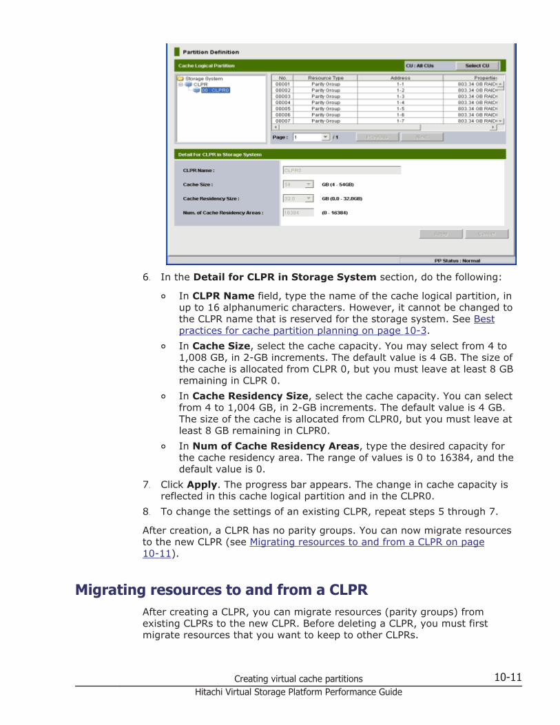
6. In the Detail for CLPR in Storage System section, do the following:
¢ In CLPR Name field, type the name of the cache logical partition, inup to 16 alphanumeric characters. However, it cannot be changed tothe CLPR name that is reserved for the storage system. See Bestpractices for cache partition planning on page 10-3.
¢ In Cache Size, select the cache capacity. You may select from 4 to1,008 GB, in 2-GB increments. The default value is 4 GB. The size ofthe cache is allocated from CLPR 0, but you must leave at least 8 GBremaining in CLPR 0.
¢ In Cache Residency Size, select the cache capacity. You can selectfrom 4 to 1,004 GB, in 2-GB increments. The default value is 4 GB.The size of the cache is allocated from CLPR0, but you must leave atleast 8 GB remaining in CLPR0.
¢ In Num of Cache Residency Areas, type the desired capacity forthe cache residency area. The range of values is 0 to 16384, and thedefault value is 0.
7. Click Apply. The progress bar appears. The change in cache capacity isreflected in this cache logical partition and in the CLPR0.
8. To change the settings of an existing CLPR, repeat steps 5 through 7.
After creation, a CLPR has no parity groups. You can now migrate resourcesto the new CLPR (see Migrating resources to and from a CLPR on page10-11).
Migrating resources to and from a CLPRAfter creating a CLPR, you can migrate resources (parity groups) fromexisting CLPRs to the new CLPR. Before deleting a CLPR, you must firstmigrate resources that you want to keep to other CLPRs.
Creating virtual cache partitions 10-11Hitachi Virtual Storage Platform Performance Guide
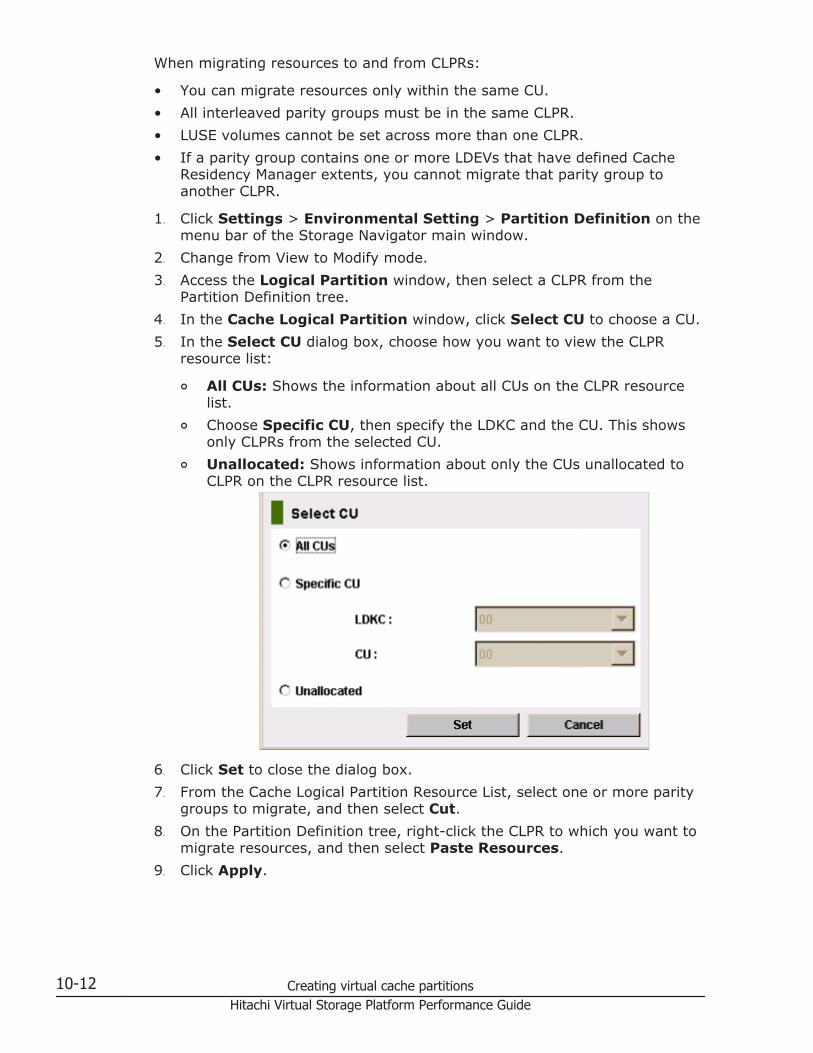
When migrating resources to and from CLPRs:
• You can migrate resources only within the same CU.• All interleaved parity groups must be in the same CLPR.• LUSE volumes cannot be set across more than one CLPR.• If a parity group contains one or more LDEVs that have defined Cache
Residency Manager extents, you cannot migrate that parity group toanother CLPR.
1. Click Settings > Environmental Setting > Partition Definition on themenu bar of the Storage Navigator main window.
2. Change from View to Modify mode.3. Access the Logical Partition window, then select a CLPR from the
Partition Definition tree.4. In the Cache Logical Partition window, click Select CU to choose a CU.5. In the Select CU dialog box, choose how you want to view the CLPR
resource list:
¢ All CUs: Shows the information about all CUs on the CLPR resourcelist.
¢ Choose Specific CU, then specify the LDKC and the CU. This showsonly CLPRs from the selected CU.
¢ Unallocated: Shows information about only the CUs unallocated toCLPR on the CLPR resource list.
6. Click Set to close the dialog box.7. From the Cache Logical Partition Resource List, select one or more parity
groups to migrate, and then select Cut.8. On the Partition Definition tree, right-click the CLPR to which you want to
migrate resources, and then select Paste Resources.9. Click Apply.
10-12 Creating virtual cache partitionsHitachi Virtual Storage Platform Performance Guide
Deleting a CLPR Before deleting a CLPR, migrate all resources (for example, parity groups)that you want to keep to another CLPR that will not be deleted (see Migratingresources to and from a CLPR on page 10-11).
You can delete CLPRs that you created; CLPR0 cannot be deleted.
1. Click Settings>Environmental Setting>Partition Definition on themenu bar of the Storage Navigator main window.
2. Change from View to Modify mode.3. Select a CLPR in the Partition Definition tree to open the Cache Logical
Partition window.4. Right-click the CLPR that you want to delete, and then select Delete
CLPR.5. Click Apply.
Troubleshooting Virtual Partition ManagerThe next table lists troubleshooting information for Virtual Partition Managertasks.
Error Cause
When you try to migrate a paritygroup to another CLPR, an LUwarning message appears.
LUSE volumes cannot be set across more than oneCLPR.
The CLPR name cannot bechanged.
You cannot assign the same name to more than oneCLPR. The name you entered is already in use or is areserved name. Enter another name. For moreinformation, see Default CLPR names on page 10-4.
The parity group in a CLPRcannot be migrated to anotherCLPR.
• Only open-system parity groups can be migrated.• Make sure that all interleaved parity groups
belong to the same CLPR.• Click Apply when creating a new CLPR.
Viewing an error message
If a problem occurs after you click Apply, the system generates an errormessage that provides information about and recommended action for theerror condition.
To view an error message, right-click a CLPR on the Partition Definition tree,and then select Error Detail to open the message. Click OK to close theerror message.
Creating virtual cache partitions 10-13Hitachi Virtual Storage Platform Performance Guide

10-14 Creating virtual cache partitionsHitachi Virtual Storage Platform Performance Guide
11Estimating cache size
This topic describes how to estimate the cache size required for using CacheResidency Manager.
□ About cache size
□ Calculating cache size for open systems
□ Calculating cache size for mainframe systems
□ Cache Residency Manager cache areas
□ Cache Residency Manager system specifications
Estimating cache size 11-1Hitachi Virtual Storage Platform Performance Guide
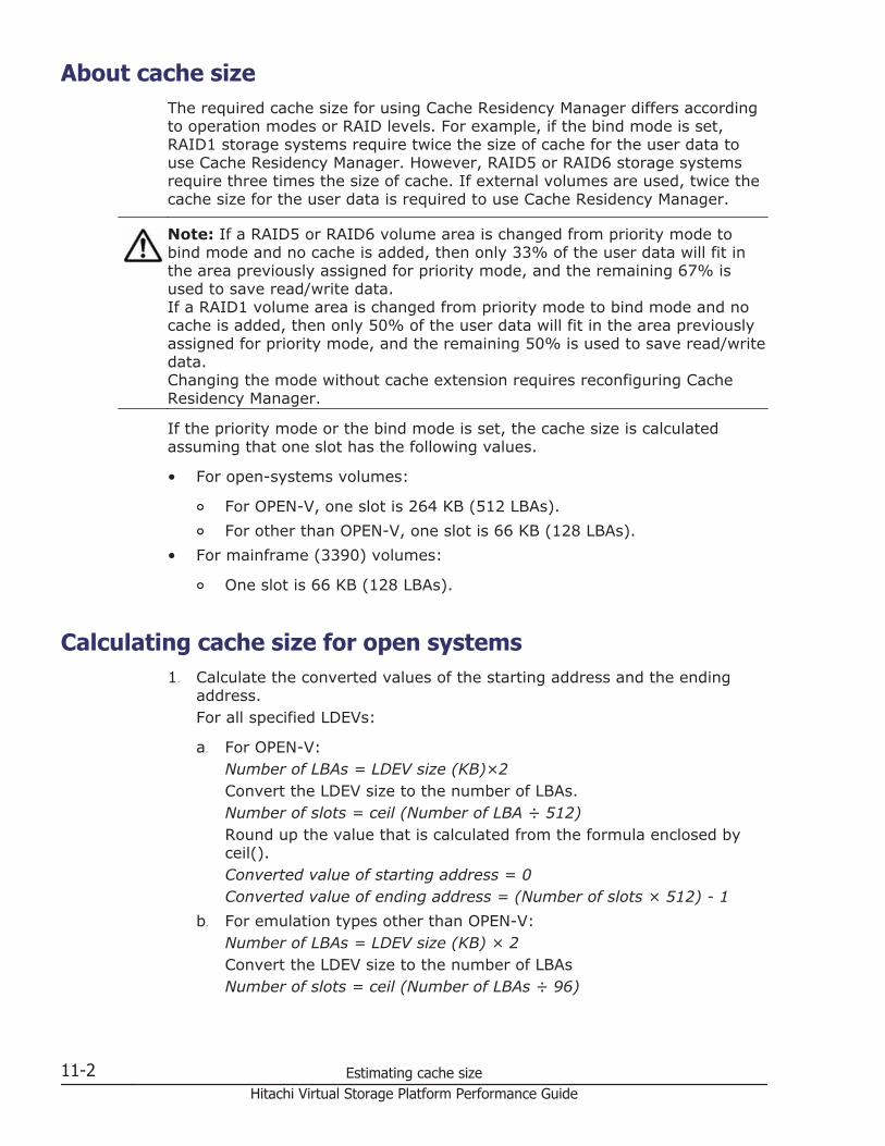
About cache sizeThe required cache size for using Cache Residency Manager differs accordingto operation modes or RAID levels. For example, if the bind mode is set,RAID1 storage systems require twice the size of cache for the user data touse Cache Residency Manager. However, RAID5 or RAID6 storage systemsrequire three times the size of cache. If external volumes are used, twice thecache size for the user data is required to use Cache Residency Manager.
Note: If a RAID5 or RAID6 volume area is changed from priority mode tobind mode and no cache is added, then only 33% of the user data will fit inthe area previously assigned for priority mode, and the remaining 67% isused to save read/write data.If a RAID1 volume area is changed from priority mode to bind mode and nocache is added, then only 50% of the user data will fit in the area previouslyassigned for priority mode, and the remaining 50% is used to save read/writedata.Changing the mode without cache extension requires reconfiguring CacheResidency Manager.
If the priority mode or the bind mode is set, the cache size is calculatedassuming that one slot has the following values.
• For open-systems volumes:
¢ For OPEN-V, one slot is 264 KB (512 LBAs).¢ For other than OPEN-V, one slot is 66 KB (128 LBAs).
• For mainframe (3390) volumes:
¢ One slot is 66 KB (128 LBAs).
Calculating cache size for open systems1. Calculate the converted values of the starting address and the ending
address.For all specified LDEVs:
a. For OPEN-V:Number of LBAs = LDEV size (KB)×2Convert the LDEV size to the number of LBAs.Number of slots = ceil (Number of LBA ÷ 512)Round up the value that is calculated from the formula enclosed byceil().Converted value of starting address = 0Converted value of ending address = (Number of slots × 512) - 1
b. For emulation types other than OPEN-V:Number of LBAs = LDEV size (KB) × 2Convert the LDEV size to the number of LBAsNumber of slots = ceil (Number of LBAs ÷ 96)
11-2 Estimating cache sizeHitachi Virtual Storage Platform Performance Guide
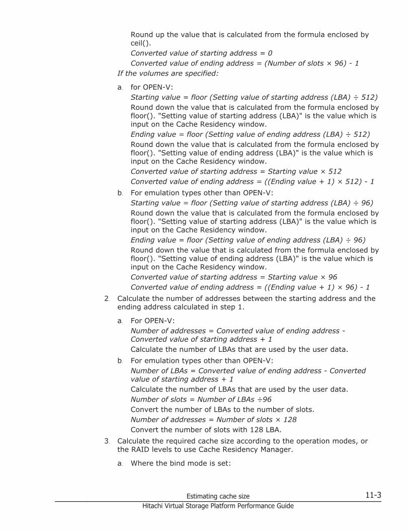
Round up the value that is calculated from the formula enclosed byceil().Converted value of starting address = 0Converted value of ending address = (Number of slots × 96) - 1
If the volumes are specified:
a. for OPEN-V:Starting value = floor (Setting value of starting address (LBA) ÷ 512)Round down the value that is calculated from the formula enclosed byfloor(). "Setting value of starting address (LBA)" is the value which isinput on the Cache Residency window.Ending value = floor (Setting value of ending address (LBA) ÷ 512)Round down the value that is calculated from the formula enclosed byfloor(). "Setting value of ending address (LBA)" is the value which isinput on the Cache Residency window.Converted value of starting address = Starting value × 512Converted value of ending address = ((Ending value + 1) × 512) - 1
b. For emulation types other than OPEN-V:Starting value = floor (Setting value of starting address (LBA) ÷ 96)Round down the value that is calculated from the formula enclosed byfloor(). "Setting value of starting address (LBA)" is the value which isinput on the Cache Residency window.Ending value = floor (Setting value of ending address (LBA) ÷ 96)Round down the value that is calculated from the formula enclosed byfloor(). "Setting value of ending address (LBA)" is the value which isinput on the Cache Residency window.Converted value of starting address = Starting value × 96Converted value of ending address = ((Ending value + 1) × 96) - 1
2. Calculate the number of addresses between the starting address and theending address calculated in step 1.
a. For OPEN-V:Number of addresses = Converted value of ending address -Converted value of starting address + 1Calculate the number of LBAs that are used by the user data.
b. For emulation types other than OPEN-V:Number of LBAs = Converted value of ending address - Convertedvalue of starting address + 1Calculate the number of LBAs that are used by the user data.Number of slots = Number of LBAs ÷96Convert the number of LBAs to the number of slots.Number of addresses = Number of slots × 128Convert the number of slots with 128 LBA.
3. Calculate the required cache size according to the operation modes, orthe RAID levels to use Cache Residency Manager.
a. Where the bind mode is set:
Estimating cache size 11-3Hitachi Virtual Storage Platform Performance Guide
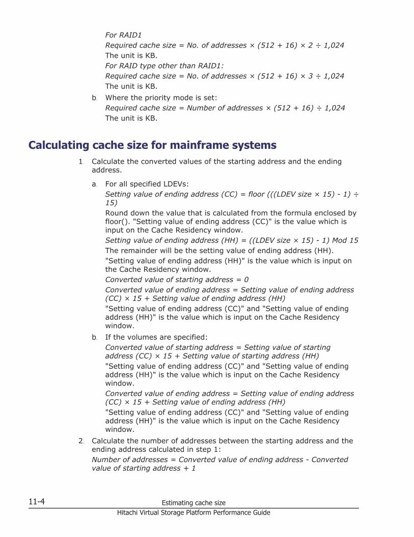
For RAID1Required cache size = No. of addresses × (512 + 16) × 2 ÷ 1,024The unit is KB.For RAID type other than RAID1:Required cache size = No. of addresses × (512 + 16) × 3 ÷ 1,024The unit is KB.
b. Where the priority mode is set:Required cache size = Number of addresses × (512 + 16) ÷ 1,024The unit is KB.
Calculating cache size for mainframe systems1. Calculate the converted values of the starting address and the ending
address.
a. For all specified LDEVs:Setting value of ending address (CC) = floor (((LDEV size × 15) - 1) ÷15)Round down the value that is calculated from the formula enclosed byfloor(). "Setting value of ending address (CC)" is the value which isinput on the Cache Residency window.Setting value of ending address (HH) = ((LDEV size × 15) - 1) Mod 15The remainder will be the setting value of ending address (HH)."Setting value of ending address (HH)" is the value which is input onthe Cache Residency window.Converted value of starting address = 0Converted value of ending address = Setting value of ending address(CC) × 15 + Setting value of ending address (HH)"Setting value of ending address (CC)" and "Setting value of endingaddress (HH)" is the value which is input on the Cache Residencywindow.
b. If the volumes are specified:Converted value of starting address = Setting value of startingaddress (CC) × 15 + Setting value of starting address (HH)"Setting value of ending address (CC)" and "Setting value of endingaddress (HH)" is the value which is input on the Cache Residencywindow.Converted value of ending address = Setting value of ending address(CC) × 15 + Setting value of ending address (HH)"Setting value of ending address (CC)" and "Setting value of endingaddress (HH)" is the value which is input on the Cache Residencywindow.
2. Calculate the number of addresses between the starting address and theending address calculated in step 1:Number of addresses = Converted value of ending address - Convertedvalue of starting address + 1
11-4 Estimating cache sizeHitachi Virtual Storage Platform Performance Guide
Calculate the number of addresses of cache that are used by the userdata.
3. Calculate the required cache size according to the operation modes, orthe RAID levels to use Cache Residency.
a. Where the bind mode is set:For RAID1Required cache size = (Number of addresses × ((128 × (512 + 16))× 2) ÷ 1,024The unit is KB.
b. Where the priority mode is set:Required cache size = (Number of addresses × (128 × (512 + 16)))÷ 1,024The unit is KB.
Cache Residency Manager cache areasThe Cache Residency Manager cache areas have the following parameters:
• The cache areas are dynamic and can be added and deleted at any time.• The VSP supports a maximum of 1,024 addressable cache areas per LDEV
and per storage system.• For OPEN-V volumes, Cache Residency Manager cache areas must be
defined in logical blocks using logical block addresses (LBAs), with aminimum size of 512 LBAs (equivalent to 264 KB). In most cases you willassign an entire open-systems volume for cache residency. If theremaining cache memory is less than 256 MB, Cache Residency Manageris not available.
• For mainframe volumes, Cache Residency Manager cache areas must bedefined on contiguous tracks with a minimum size of one cache slot (ortrack) (equivalent to 66 KB) and a maximum size of one LVI.
• You can prestage the data to the resident cache area. If prestaging is notused, the data will be loaded into the Cache Residency Manager areawhen the first “miss” occurs. If prestaging is used, performance may beaffected for a short time while the data is read into Cache ResidencyManager cache.
Caution: Prestaging of Cache Residency Manager data should not beperformed during peak activity.
• All write I/Os to Cache Residency Manager data are duplex writes,guaranteeing full data integrity. The Cache Residency Manager dataremains fixed in cache until you manually delete it. Deletion of CacheResidency Manager cache areas destages any write data to the affectedvolumes.
• It is possible to expand the amount of Cache Residency Manager cachewithout canceling the existing Cache Residency Manager settings. Fordetails, call the Support Center.
Estimating cache size 11-5Hitachi Virtual Storage Platform Performance Guide
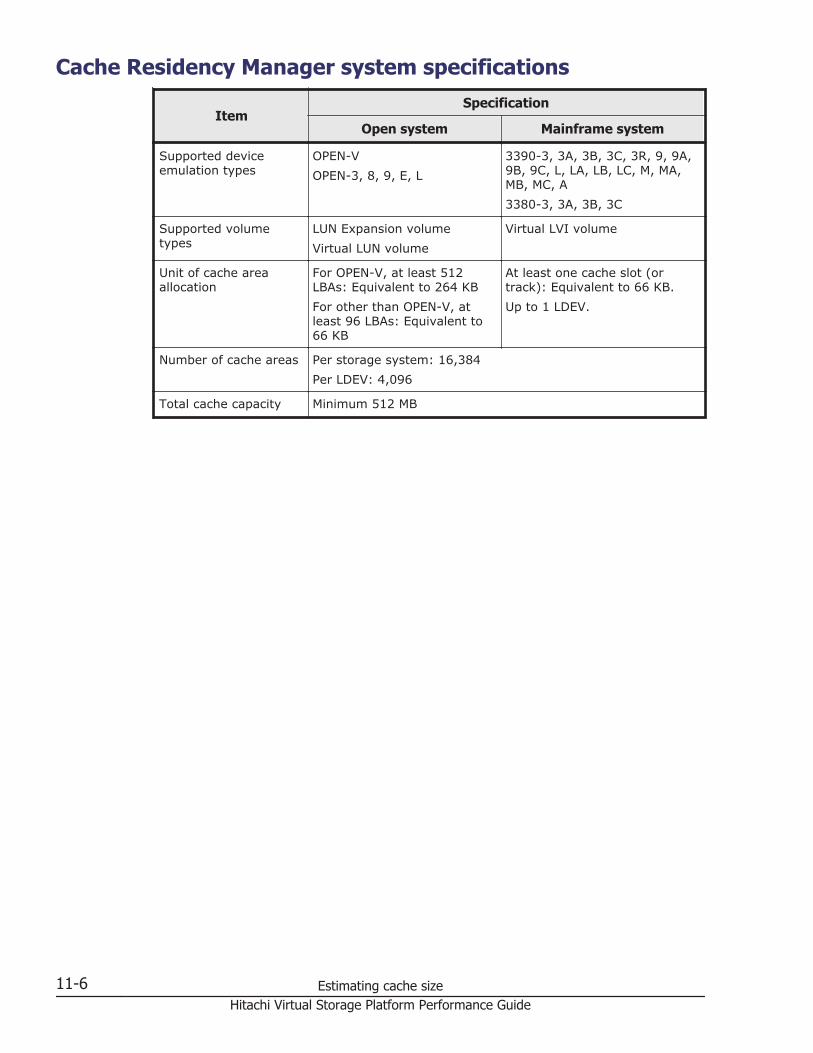
Cache Residency Manager system specifications
ItemSpecification
Open system Mainframe system
Supported deviceemulation types
OPEN-VOPEN-3, 8, 9, E, L
3390-3, 3A, 3B, 3C, 3R, 9, 9A,9B, 9C, L, LA, LB, LC, M, MA,MB, MC, A3380-3, 3A, 3B, 3C
Supported volumetypes
LUN Expansion volumeVirtual LUN volume
Virtual LVI volume
Unit of cache areaallocation
For OPEN-V, at least 512LBAs: Equivalent to 264 KBFor other than OPEN-V, atleast 96 LBAs: Equivalent to66 KB
At least one cache slot (ortrack): Equivalent to 66 KB.Up to 1 LDEV.
Number of cache areas Per storage system: 16,384Per LDEV: 4,096
Total cache capacity Minimum 512 MB
11-6 Estimating cache sizeHitachi Virtual Storage Platform Performance Guide
12Managing resident cache
This topic provides instructions for using Cache Residency Manager softwareto manage resident cache.
□ Cache Residency Manager rules, restrictions, and guidelines
□ Launching Cache Residency
□ Viewing Cache Residency information
□ Placing specific data into Cache Residency Manager cache
□ Placing LDEVs into Cache Residency Manager cache
□ Releasing specific data from Cache Residency Manager cache
□ Releasing LDEVs from Cache Residency Manager cache
□ Changing mode after Cache Residency is registered in cache
Managing resident cache 12-1Hitachi Virtual Storage Platform Performance Guide
Cache Residency Manager rules, restrictions, and guidelines
Rules
• Cache Residency Manager must be enabled on Storage Navigator.• Administrator or Cache Residency Manager write access to the Storage
Navigator software is required to perform Cache Residency Manageroperations. Users without write access can view Cache ResidencyManager information for the connected storage system but cannot set orchange options.
• Do not attempt to allocate Cache Residency Manager cache beyond theallocated capacity.
• Do not apply Cache Residency Manager settings to volumes reserved forVolume Migration.
• Do not attempt to allocate Cache Residency Manager cache redundantlyover the cache area that is already allocated to an LDEV.
• Do not apply or refer to Cache Residency Manager settings to volumesfrom the host and Storage Navigator at the same time. You can apply thesettings from the host if you use Cache Manager.
• If you specify the Cache Residency Manager setting on the volume duringquick formatting, do not use the prestaging function. If you want to usethe prestaging function after the quick formatting processing completes,release the setting and then specify the Cache Residency Manager settingagain, with the prestaging setting enabled this time. For informationabout quick formatting, see the Provisioning Guide for Open Systems orthe Provisioning Guide for Mainframe Systems.
• Do not perform the ShadowImage quick restore operation or the VolumeMigration operation on a Cache Residency Manager volume. Also, do notspecify the Cache Residency Manager setting on the volume on which theShadowImage quick restore or Volume Migration operation is performed.These operations swap the internal locations of the source and targetvolumes, which causes a loss of data integrity. For additional information,see the Hitachi ShadowImage® User Guide and/or contact Hitachi DataSystems Support Center.
• To set Cache Residency Manager for a LUSE volume, you must set CacheResidency Manager for an LDEV that is a component of the LUSE volume.To determine the LDEV for which you want to set Cache Residency, youmust know the exact number of LBAs in each LDEV that is a component ofthe LUSE volume.
Note: The number of LBAs displayed on the Cache Residency window isdifferent from the actual number of LDEVs, and does not match thenumber of LBAs recognized by the host.To identify the exact number of LBAs in a LDEV, first display the StorageNavigator main window and search for the parity group to which the LDEVbelongs according to the LDKC, control unit (CU), and LDEV numbers. Formore information about the Basic Information Display window, see theHitachi Storage Navigator User Guide.
12-2 Managing resident cacheHitachi Virtual Storage Platform Performance Guide
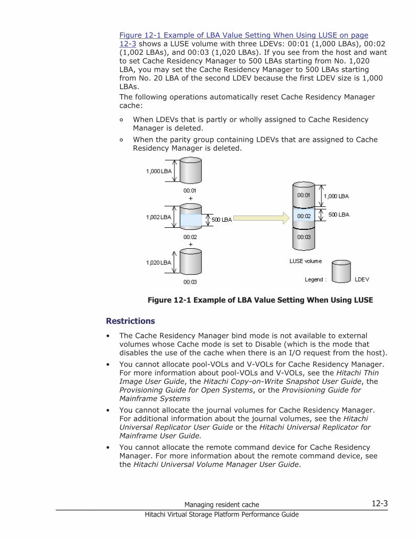
Figure 12-1 Example of LBA Value Setting When Using LUSE on page12-3 shows a LUSE volume with three LDEVs: 00:01 (1,000 LBAs), 00:02(1,002 LBAs), and 00:03 (1,020 LBAs). If you see from the host and wantto set Cache Residency Manager to 500 LBAs starting from No. 1,020LBA, you may set the Cache Residency Manager to 500 LBAs startingfrom No. 20 LBA of the second LDEV because the first LDEV size is 1,000LBAs.The following operations automatically reset Cache Residency Managercache:
¢ When LDEVs that is partly or wholly assigned to Cache ResidencyManager is deleted.
¢ When the parity group containing LDEVs that are assigned to CacheResidency Manager is deleted.
Figure 12-1 Example of LBA Value Setting When Using LUSE
Restrictions
• The Cache Residency Manager bind mode is not available to externalvolumes whose Cache mode is set to Disable (which is the mode thatdisables the use of the cache when there is an I/O request from the host).
• You cannot allocate pool-VOLs and V-VOLs for Cache Residency Manager.For more information about pool-VOLs and V-VOLs, see the Hitachi ThinImage User Guide, the Hitachi Copy-on-Write Snapshot User Guide, theProvisioning Guide for Open Systems, or the Provisioning Guide forMainframe Systems
• You cannot allocate the journal volumes for Cache Residency Manager.For additional information about the journal volumes, see the HitachiUniversal Replicator User Guide or the Hitachi Universal Replicator forMainframe User Guide.
• You cannot allocate the remote command device for Cache ResidencyManager. For more information about the remote command device, seethe Hitachi Universal Volume Manager User Guide.
Managing resident cache 12-3Hitachi Virtual Storage Platform Performance Guide
• You cannot allocate a quorum disk used with High Availability Manager forCache Residency Manager.
• You cannot allocate the nondisruptive migration volumes for CacheResidency Manager.
Guidelines
• Performing Cache Residency Manager operations on many LDEVs duringhost I/O may cause the host I/O response time to become slow. To avoiddegradation of response time, set only one LDEV at a time.
• Deleting data from cache during host I/O may cause the response time ofhost I/O to become slow. To avoid degradation of host response time,limit the amount of data you delete in one operation as follows:If the host timeout period is set to 10 seconds or shorter, limit the totalamount of data to:
¢ 1 GB or less for open systems¢ 1,000 cylinders or less for mainframe systemsIf the host timeout period is set to 11 seconds or longer, limit the totalamount of data to:
¢ 3 GB or less for open systems¢ 3,000 cylinders or less for mainframe systems
Launching Cache Residency1. Log on to the primary SVP.2. On the menu bar of the Storage Navigator main window, click Actions >
Other Function > Cache Residency.
12-4 Managing resident cacheHitachi Virtual Storage Platform Performance Guide
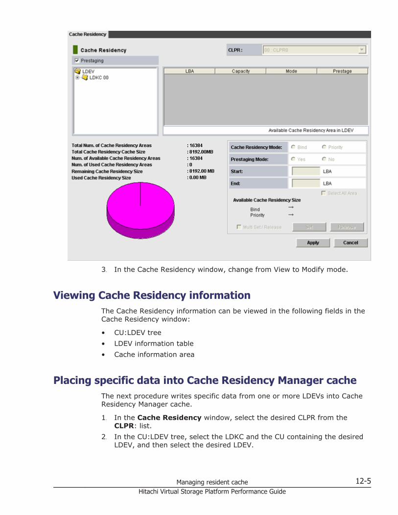
3. In the Cache Residency window, change from View to Modify mode.
Viewing Cache Residency informationThe Cache Residency information can be viewed in the following fields in theCache Residency window:
• CU:LDEV tree• LDEV information table• Cache information area
Placing specific data into Cache Residency Manager cacheThe next procedure writes specific data from one or more LDEVs into CacheResidency Manager cache.
1. In the Cache Residency window, select the desired CLPR from theCLPR: list.
2. In the CU:LDEV tree, select the LDKC and the CU containing the desiredLDEV, and then select the desired LDEV.
Managing resident cache 12-5Hitachi Virtual Storage Platform Performance Guide
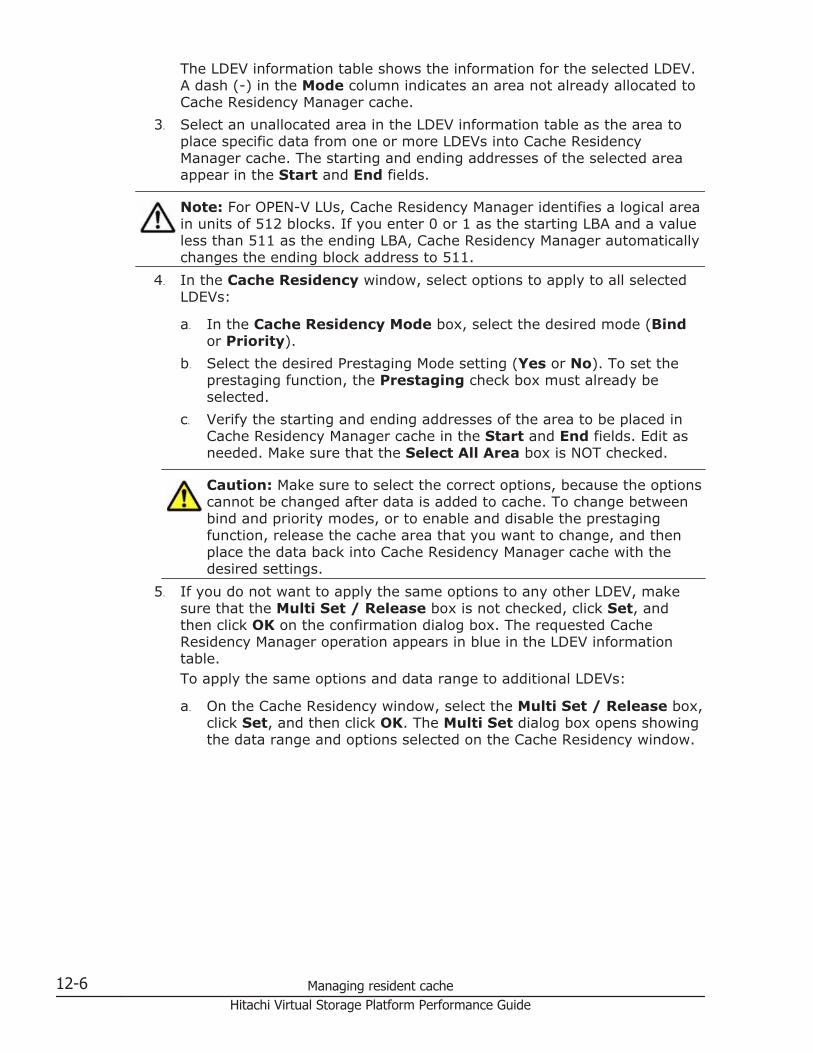
The LDEV information table shows the information for the selected LDEV.A dash (-) in the Mode column indicates an area not already allocated toCache Residency Manager cache.
3. Select an unallocated area in the LDEV information table as the area toplace specific data from one or more LDEVs into Cache ResidencyManager cache. The starting and ending addresses of the selected areaappear in the Start and End fields.
Note: For OPEN-V LUs, Cache Residency Manager identifies a logical areain units of 512 blocks. If you enter 0 or 1 as the starting LBA and a valueless than 511 as the ending LBA, Cache Residency Manager automaticallychanges the ending block address to 511.
4. In the Cache Residency window, select options to apply to all selectedLDEVs:
a. In the Cache Residency Mode box, select the desired mode (Bindor Priority).
b. Select the desired Prestaging Mode setting (Yes or No). To set theprestaging function, the Prestaging check box must already beselected.
c. Verify the starting and ending addresses of the area to be placed inCache Residency Manager cache in the Start and End fields. Edit asneeded. Make sure that the Select All Area box is NOT checked.
Caution: Make sure to select the correct options, because the optionscannot be changed after data is added to cache. To change betweenbind and priority modes, or to enable and disable the prestagingfunction, release the cache area that you want to change, and thenplace the data back into Cache Residency Manager cache with thedesired settings.
5. If you do not want to apply the same options to any other LDEV, makesure that the Multi Set / Release box is not checked, click Set, andthen click OK on the confirmation dialog box. The requested CacheResidency Manager operation appears in blue in the LDEV informationtable.To apply the same options and data range to additional LDEVs:
a. On the Cache Residency window, select the Multi Set / Release box,click Set, and then click OK. The Multi Set dialog box opens showingthe data range and options selected on the Cache Residency window.
12-6 Managing resident cacheHitachi Virtual Storage Platform Performance Guide
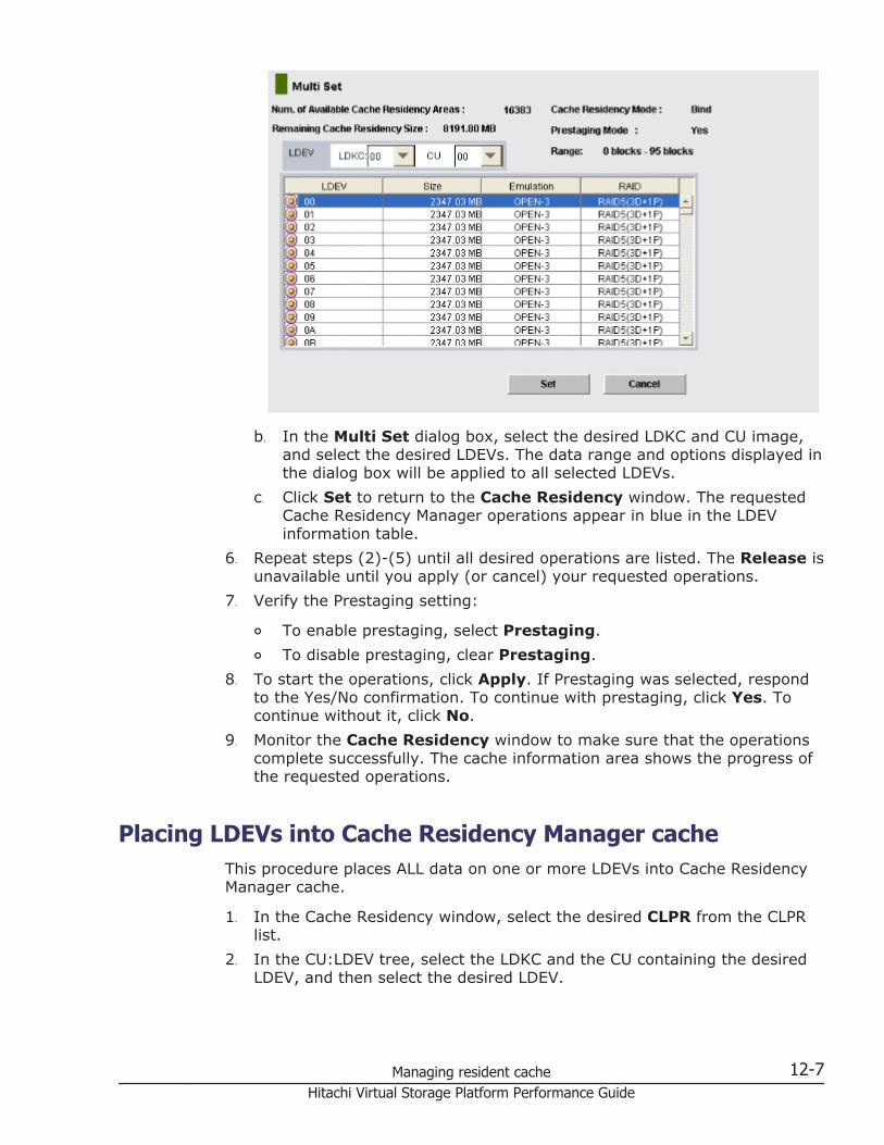
b. In the Multi Set dialog box, select the desired LDKC and CU image,and select the desired LDEVs. The data range and options displayed inthe dialog box will be applied to all selected LDEVs.
c. Click Set to return to the Cache Residency window. The requestedCache Residency Manager operations appear in blue in the LDEVinformation table.
6. Repeat steps (2)-(5) until all desired operations are listed. The Release isunavailable until you apply (or cancel) your requested operations.
7. Verify the Prestaging setting:
¢ To enable prestaging, select Prestaging.¢ To disable prestaging, clear Prestaging.
8. To start the operations, click Apply. If Prestaging was selected, respondto the Yes/No confirmation. To continue with prestaging, click Yes. Tocontinue without it, click No.
9. Monitor the Cache Residency window to make sure that the operationscomplete successfully. The cache information area shows the progress ofthe requested operations.
Placing LDEVs into Cache Residency Manager cacheThis procedure places ALL data on one or more LDEVs into Cache ResidencyManager cache.
1. In the Cache Residency window, select the desired CLPR from the CLPRlist.
2. In the CU:LDEV tree, select the LDKC and the CU containing the desiredLDEV, and then select the desired LDEV.
Managing resident cache 12-7Hitachi Virtual Storage Platform Performance Guide
The LDEV information table shows the information for the selected LDEV.A dash (-) in the Mode column indicates an area not already allocated toCache Residency Manager cache.
3. In the Cache Residency window, select desired options:
a. In the Cache Residency Mode box, select the desired mode (Bindor Priority).
b. Select the desired Prestaging Mode setting (Yes or No). To set theprestaging function, the Prestaging check box must already beselected.
c. Check the Select All Area box. Leave the Start and End fields blank.
Caution: Make sure to select the correct options, because the optionscannot be changed after a cache area is added. To change betweenbind and priority modes, or to enable and disable the prestagingfunction, you must release the cache area that you want to changeand then place the data back into Cache Residency Manager cachewith the desired settings.
4. If you do not want to apply the same options to any other LDEVs, makesure that the Multi Set / Release box is not checked, click Set, andthen click OK on the confirmation dialog box. The requested operationappears in blue in the LDEV information table.To apply the same options to additional LDEVs:
a. In the Cache Residency window, select the Multi Set / Releasebox, click Set, and then click OK. The Multi Set dialog box opensshowing the data range and options selected on the Cache Residencywindow.
b. In the Multi Set dialog box, select the desired CU image, and selectthe desired LDEVs. The options displayed on the dialog box will beapplied to all selected LDEVs.
c. Click Set to return to the Cache Residency window. The requestedCache Residency Manager operations appears in blue in the LDEVinformation table.
5. Repeat steps (2)-(4) until all desired operations are listed. The Release isunavailable until you apply (or cancel) your requested operations.
6. Verify the Prestaging setting:
¢ To enable prestaging, select Prestaging.¢ To disable prestaging, clear Prestaging.
7. To start the operations, click Apply:
¢ If Prestaging was selected, respond to the Yes/No confirmation. Tocontinue with prestaging, select Yes. To continue without it, selectNo.
¢ To cancel the operation, click Cancel and click OK on theconfirmation.
12-8 Managing resident cacheHitachi Virtual Storage Platform Performance Guide
8. Monitor the Cache Residency window to make sure that the operationscomplete successfully. The cache information area shows the progress ofthe requested operations.
Releasing specific data from Cache Residency Managercache
This procedure releases specific data areas on one or more LDEVs from CacheResidency Manager cache.
1. In the Cache Residency window, select the desired CLPR from the CLPRlist.
2. In the CU:LDEV tree, select the LDKC and the CU containing the desiredLDEV, and then select the desired LDEV.The LDEV information table shows the information for the selected LDEV.The Mode column indicates PRIO or BIND for each data area that isallocated to Cache Residency Manager cache.
3. Select the data areas that you want to release from Cache ResidencyManager cache. This enables the Release.
4. Click Release, and click OK on the confirmation message.The requested operation is displayed in blue in the LDEV informationtable.
5. Repeat steps (2)-(4) for each LDEV for which you want to release specificdata from Cache Residency Manager cache. The Set is unavailable untilyou apply (or cancel) your requested operations.
6. Verify the Prestaging setting:
¢ To enable prestaging, select Prestaging.¢ To disable prestaging, clear Prestaging.
7. To start the operations, click Apply:
¢ If Prestaging was selected, respond to the Yes/No confirmation. Tocontinue with prestaging, select Yes. To continue without it, selectNo.
¢ To cancel the operation, click Cancel and click OK on theconfirmation.
8. When the delete confirmation message appears, click OK to begin thedeletion, or click Cancel to cancel your request to delete data.
9. Monitor the Cache Residency window to make sure that the operationscomplete successfully. The cache information area shows the progress ofthe requested operations.When the data has been released, the verification window will appear.
Managing resident cache 12-9Hitachi Virtual Storage Platform Performance Guide
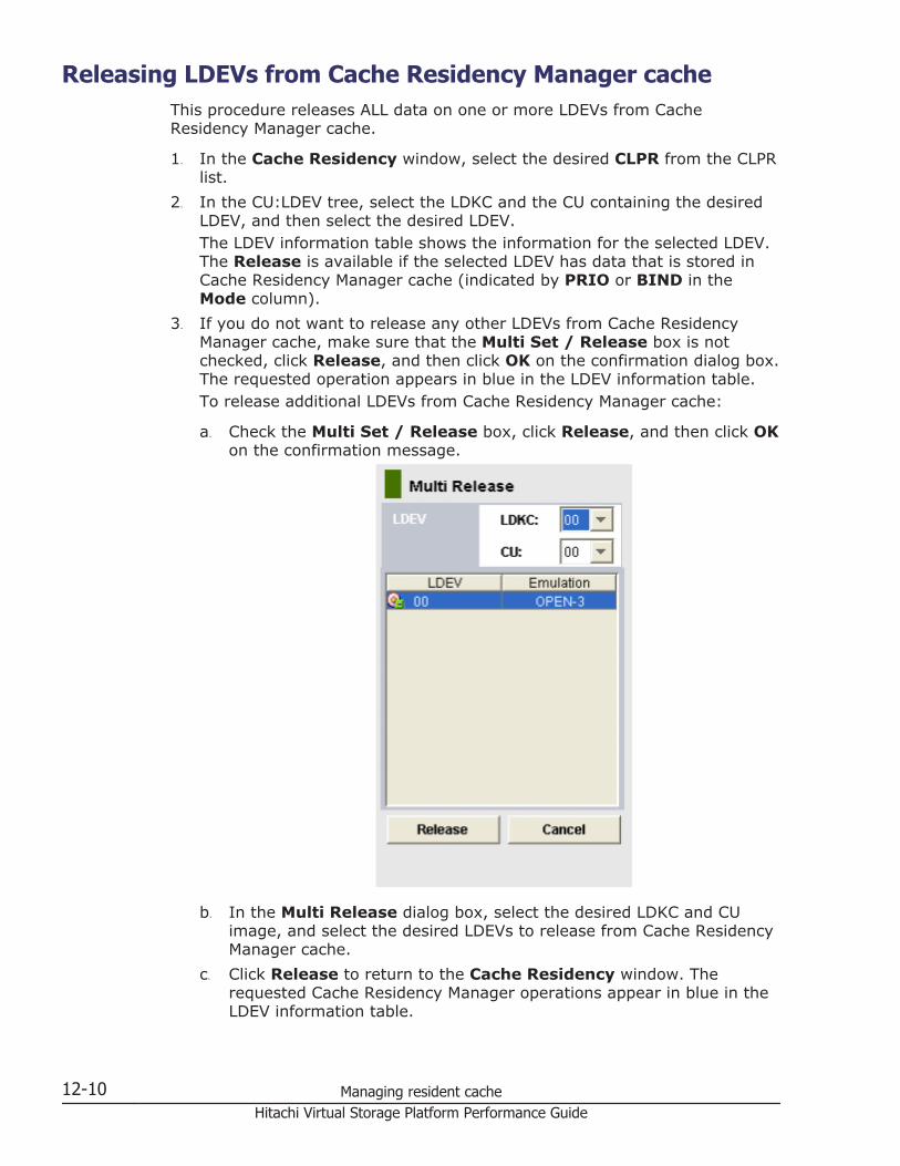
Releasing LDEVs from Cache Residency Manager cacheThis procedure releases ALL data on one or more LDEVs from CacheResidency Manager cache.
1. In the Cache Residency window, select the desired CLPR from the CLPRlist.
2. In the CU:LDEV tree, select the LDKC and the CU containing the desiredLDEV, and then select the desired LDEV.The LDEV information table shows the information for the selected LDEV.The Release is available if the selected LDEV has data that is stored inCache Residency Manager cache (indicated by PRIO or BIND in theMode column).
3. If you do not want to release any other LDEVs from Cache ResidencyManager cache, make sure that the Multi Set / Release box is notchecked, click Release, and then click OK on the confirmation dialog box.The requested operation appears in blue in the LDEV information table.To release additional LDEVs from Cache Residency Manager cache:
a. Check the Multi Set / Release box, click Release, and then click OKon the confirmation message.
b. In the Multi Release dialog box, select the desired LDKC and CUimage, and select the desired LDEVs to release from Cache ResidencyManager cache.
c. Click Release to return to the Cache Residency window. Therequested Cache Residency Manager operations appear in blue in theLDEV information table.
12-10 Managing resident cacheHitachi Virtual Storage Platform Performance Guide
4. Repeat steps (2) and (3) until all desired operations are listed.
Note: The Set is unavailable until you apply (or cancel) your requestedoperations.
5. Verify the Prestaging setting:
¢ To enable prestaging, select Prestaging.¢ To disable prestaging, clear Prestaging.
6. To start the operations, click Apply:
¢ If Prestaging was selected, respond to the Yes/No confirmation. Tocontinue with prestaging, click Yes. To continue without it, click No.
¢ To cancel the operation, click Cancel and click OK on theconfirmation.
7. Monitor the Cache Residency window to make sure that the operationscomplete successfully. The cache information area shows the progress ofthe requested operations.
Changing mode after Cache Residency is registered in cacheIf Cache Residency is registered in the cache, the following mode optionsappear gray and are unavailable for change:
• Cache Residency Mode (Bind, Priority)• Prestaging Mode (Yes, No)
To change the mode options:
1. Release the specific data from the Cache Residency cache. For details, seeReleasing specific data from Cache Residency Manager cache on page12-9.
2. Restore the data with the new settings. For details, see Placing specificdata into Cache Residency Manager cache on page 12-5.
Managing resident cache 12-11Hitachi Virtual Storage Platform Performance Guide

12-12 Managing resident cacheHitachi Virtual Storage Platform Performance Guide
13Troubleshooting
This topic provides references to sources of troubleshooting and contactinformation for Hitachi Data Systems Support Center.
□ Troubleshooting resources
□ Calling Hitachi Data Systems Support Center
Troubleshooting 13-1Hitachi Virtual Storage Platform Performance Guide
Troubleshooting resourcesFor troubleshooting information on the VSP, see the Hitachi Virtual StoragePlatform User and Reference Guide.
For troubleshooting information on the Storage Navigator software, see theHitachi Storage Navigator User Guide.
For information on Storage Navigator error codes, see the Hitachi StorageNavigator Messages.
Calling Hitachi Data Systems Support CenterIf you need to call Hitachi Data Systems Support Center, make sure you canprovide as much information about the problem as possible.
Call 1-800-446-0744.
To ensure a successful call, do the following:
• Describe the circumstances surrounding the error or failure• Collect the Storage Navigator configuration information saved in the
floppy diskettes by the FD Dump Tool• Print and save the exact content of messages displayed on the Storage
Navigator• Print and save the severity levels and reference codes displayed on the
Status tab of the Storage Navigator main window. See the HitachiStorage Navigator Messages.
13-2 TroubleshootingHitachi Virtual Storage Platform Performance Guide
AExport Tool
This topic explains how to export the monitoring data collected on yourstorage system into files.
□ About the Export Tool
□ Installing the Export Tool
□ Using the Export Tool
□ Export Tool command reference
□ Exported files
□ Causes of Invalid Monitoring Data
□ Troubleshooting the Export Tool
Export Tool A-1Hitachi Virtual Storage Platform Performance Guide
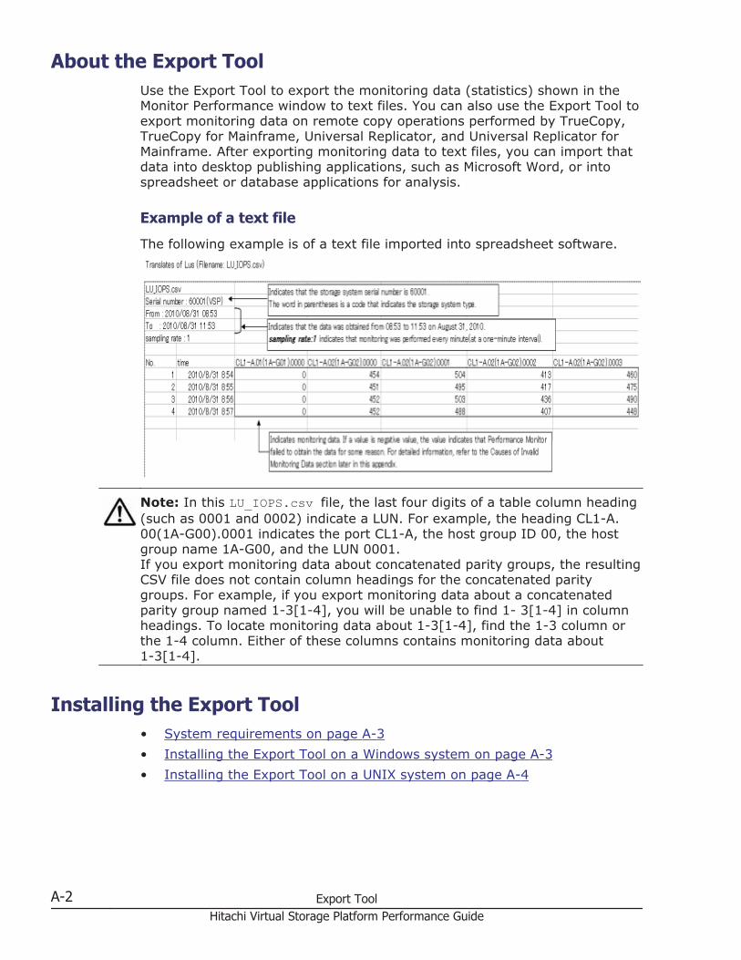
About the Export ToolUse the Export Tool to export the monitoring data (statistics) shown in theMonitor Performance window to text files. You can also use the Export Tool toexport monitoring data on remote copy operations performed by TrueCopy,TrueCopy for Mainframe, Universal Replicator, and Universal Replicator forMainframe. After exporting monitoring data to text files, you can import thatdata into desktop publishing applications, such as Microsoft Word, or intospreadsheet or database applications for analysis.
Example of a text file
The following example is of a text file imported into spreadsheet software.
Note: In this LU_IOPS.csv file, the last four digits of a table column heading(such as 0001 and 0002) indicate a LUN. For example, the heading CL1-A.00(1A-G00).0001 indicates the port CL1-A, the host group ID 00, the hostgroup name 1A-G00, and the LUN 0001.If you export monitoring data about concatenated parity groups, the resultingCSV file does not contain column headings for the concatenated paritygroups. For example, if you export monitoring data about a concatenatedparity group named 1-3[1-4], you will be unable to find 1- 3[1-4] in columnheadings. To locate monitoring data about 1-3[1-4], find the 1-3 column orthe 1-4 column. Either of these columns contains monitoring data about1-3[1-4].
Installing the Export Tool• System requirements on page A-3• Installing the Export Tool on a Windows system on page A-3• Installing the Export Tool on a UNIX system on page A-4
A-2 Export ToolHitachi Virtual Storage Platform Performance Guide
System requirementsThe following components are required to use the Export Tool (for moreinformation, see the Hitachi Storage Navigator User Guide):
• A Windows system or a UNIX systemThe Export Tool runs on Windows systems and UNIX systems that can runthe Storage Navigator software. If your Windows or UNIX system isunable to run Storage Navigator, your system is unable to run the ExportTool.
Note: If a firewall exists between the Storage Navigator computer andthe SVP, see Chapter 2 of the Hitachi Storage Navigator User Guide. Inthe section “Setting up TCP/IP for a firewall”, the RMI port numbers listedare the only direct communication settings required for the Export Tool.
• The Java Runtime Environment (JRE)To be able to use the Export Tool, you must install Java RuntimeEnvironment on your Windows or UNIX system. If your system runsStorage Navigator, JRE is already installed on your system and you caninstall the Export Tool. If your system does not run Storage Navigator butcontains an appropriate version of JRE, you can install the Export Tool onyour system.The JRE version required for running the Export Tool is the same as theJRE version required for running Storage Navigator.
• A user ID for exclusive use of the Export ToolBefore you can use the Export Tool, you must create a user ID forexclusive use of the Export Tool. Assign only the Storage Administrator(Performance Management) role to the user ID for the Export Tool. It isrecommended that you do not assign any roles other than the StorageAdministrator (Performance Management) role to this user ID. The userwho is assigned to the Storage Administrator (Performance Management)role can do the following:
¢ Save the monitoring data into files¢ Change the gathering interval¢ Start or stop monitoring by the set subcommandFor details on creating the user ID, see the Hitachi Storage NavigatorUser Guide.
• The Export Tool programCD-ROM Disc 2, which is named Host PP, contains the Export Toolsoftware. For instructions on installing the Export Tool, see:
¢ Installing the Export Tool on a Windows system on page A-3¢ Installing the Export Tool on a UNIX system on page A-4
Installing the Export Tool on a Windows systemThe Export Tool program is a Java class file and is located in the export\libfolder.
Export Tool A-3Hitachi Virtual Storage Platform Performance Guide
1. Log on with administrator privileges.2. Create a new folder for the Export Tool application (for example, C:
\Program Files\monitor). If this folder already exists, skip this step.3. Insert the Export Tool CD-ROM into the CD drive.4. Locate the \program\monitor\win_nt folder on the CD-ROM, and copy
the self-extracting file export.exe from the CD-ROM into the new folderyou just created.
5. Double-click export.exe to start the installation. The Export Tool isinstalled, and a new folder named “export” is created.
6. If you are reinstalling the Export Tool to the same place as given in step2, then move the file to another location in advance in order to preventthe file, which you have edited from being overwritten. While you arereinstalling, when the overwrite confirmation dialogue appears in step 5,click Yes.
Installing the Export Tool on a UNIX systemThe Export Tool program is a Java class file and is located in the libdirectory.
1. Log on as a superuser.You do not need to remove a previous installation of Export Tool. The newinstallation overwrites the older program.
2. Create a new directory for the Export Tool program (for example, /monitor).
3. Mount the Export Tool CD-ROM.4. Go to the /program/monitor/UNIX directory on the CD-ROM, and copy
the export.tar file to the new directory you just created.5. Decompress the export.tar file on your system. The Export Tool is
installed into the installation directory.
Note: If you are reinstalling the Export Tool to the same place as specified instep 2, then move the file to another location in advance. This will preventthe file which you have edited from being overwritten.
Using the Export ToolTo be able to export monitoring data, you must first prepare a command fileand a batch file, and then you can run the Export Tool to export monitoringdata.
• Preparing a command file on page A-5• Preparing a batch file on page A-8• Running the Export Tool on page A-10
A-4 Export ToolHitachi Virtual Storage Platform Performance Guide
Preparing a command fileBefore you run the Export Tool, you must write scripts for exportingmonitoring data. When writing scripts, you need to write severalsubcommands in a command file. When you run the Export Tool, thesubcommands in the command file are executed sequentially, and then themonitoring data is saved in files.
Example of a command filesvpip 158.214.135.57 ; Specifies IP address of SVPlogin expusr passwd ; Logs user into SVPshow ; Outputs storing period to standard ; outputgroup PhyPG Long ; Specifies type of data to be ; exported and type of ; storing periodgroup RemoteCopy ; Specifies type of data to be ; exportedshort-range 201210010850:201210010910 ; Specifies term of data to be ; exported for data stored ; in short rangelong-range 201209301430:201210011430 ; Specifies term of data to be ; exported for data stored ; in long rangeoutpath out ; Specifies directory in which files ; will be savedoption compress ; Specifies whether to compress filesapply ; Executes processing for saving ; monitoring data in filesA semicolon (;) indicates the beginning of a comment. Characters from asemicolon to the end of the line are comments.
The scripts in this command file are explained as follows:
• svpip 158.214.135.57This script specifies that you are logging into SVP whose IP address is158.214.135.57. You must log into SVP when using the Export Tool.The svpip subcommand specifies the IP address of SVP. You must includethe svpip subcommand in your command file. For detailed informationabout the svpip subcommand, see svpip on page A-16.
• login expusr passwdThis script specifies that you use the user ID expusr and the passwordpasswd to log into SVP.The login subcommand logs the specified user into SVP. You mustinclude the login subcommand in your command file. For detailedinformation about the login subcommand, see login on page A-17.
Caution: When you write the login subcommand in your command file,you must specify a user ID that should be used exclusively for runningthe Export Tool. See System requirements on page A-3 for reference.
Export Tool A-5Hitachi Virtual Storage Platform Performance Guide
• showThe show subcommand checks SVP to find the period of monitoring datastored in SVP and the data collection interval (called gathering interval inPerformance Monitor), and then outputs them to the standard output (forexample, the command prompt) and the log file.Performance Monitor collects statistics by the two types of storingperiods: in short range and in long range. The show subcommand displaysthe storing periods and the gathering intervals for these two types ofmonitoring data.The following is an example of information that the show subcommandoutputs:Short Range From: 2012/10/01 01:00 - To: 2012/10/01 15:00Interval: 1min. Long Range From: 2012/09/01 00:00 - To:2012/10/01 15:00 Interval: 15min.Short Range indicates the storing period and gathering interval of themonitoring data stored in short range. Long Range indicates those of themonitoring data stored in long range. In the above example, themonitoring data in short range is stored every 1 minute in the term of1:00-15:00 on Oct. 1, 2012. Also, the monitoring data in long range isstored every 15 minutes in the term of Sep. 1, 2012, 0:00 through Oct.1, 2012, 15:00. When you run the Export Tool, you can export monitoringdata within these periods into files.All the monitoring items are stored in short range, but a part ofmonitoring items is stored in both the short range and long range. Fordetails on monitoring items that can be stored in long range, see long-range on page A-36.The use of the show subcommand is not mandatory, but it isrecommended that you include the show subcommand in your commandfile. If an error occurs when you run the Export Tool, you might be able tofind the error cause by checking the log file for information issued by theshow subcommand. For detailed information about the showsubcommand, see show on page A-18.
• group PhyPG Long and group RemoteCopyThe group subcommand specifies the type of data that you want toexport. Specify a operand following group to define the type of data to beexported. Basically, monitoring data stored in short range is exported. Butyou can direct to export monitoring data stored in long range when youspecify some of the operands.The example script group PhyPG Long in Preparing a command file onpage A-5 specifies to export usage statistics about parity groups in longrange. Also, the script group RemoteCopy specifies to export statisticsabout remote copy operations by TrueCopy and TrueCopy for Mainframein short range. You can describe multiple lines of the group subcommandto export multiple monitoring items at the same time.For detailed information about the group subcommand, see group onpage A-19.
• short-range 201210010850:201210010910 and long-range201209301430:201210011430
A-6 Export ToolHitachi Virtual Storage Platform Performance Guide
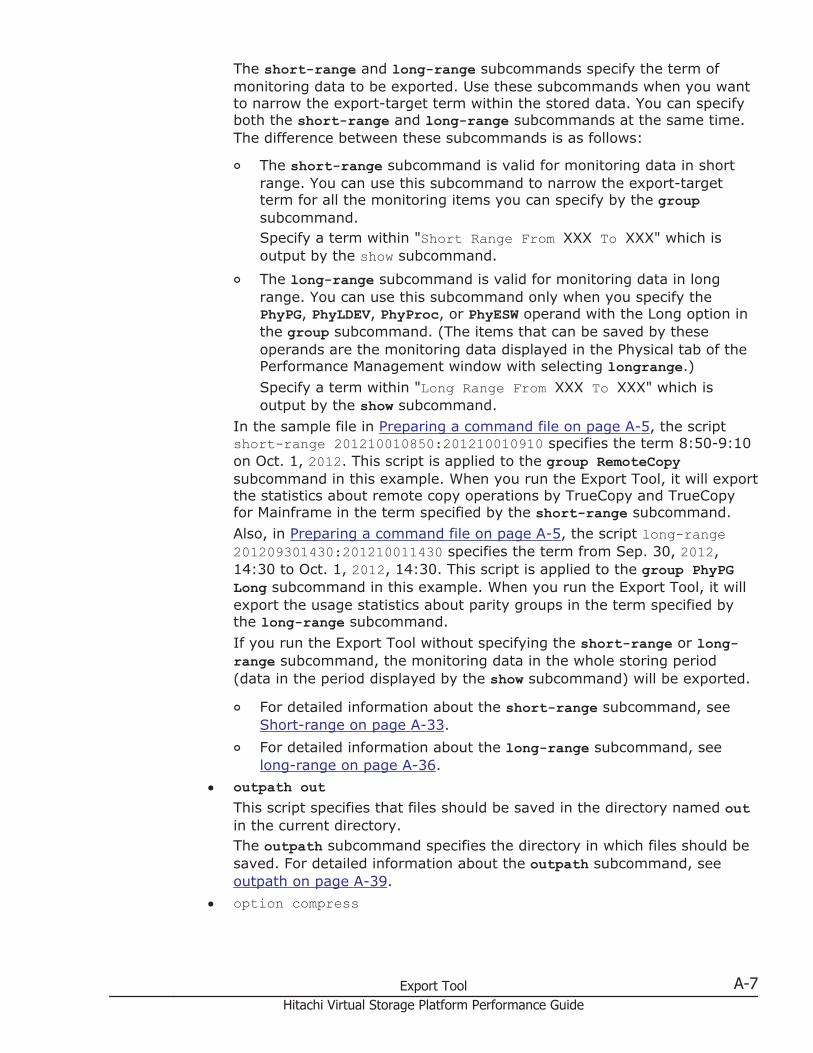
The short-range and long-range subcommands specify the term ofmonitoring data to be exported. Use these subcommands when you wantto narrow the export-target term within the stored data. You can specifyboth the short-range and long-range subcommands at the same time.The difference between these subcommands is as follows:
¢ The short-range subcommand is valid for monitoring data in shortrange. You can use this subcommand to narrow the export-targetterm for all the monitoring items you can specify by the groupsubcommand.Specify a term within "Short Range From XXX To XXX" which isoutput by the show subcommand.
¢ The long-range subcommand is valid for monitoring data in longrange. You can use this subcommand only when you specify thePhyPG, PhyLDEV, PhyProc, or PhyESW operand with the Long option inthe group subcommand. (The items that can be saved by theseoperands are the monitoring data displayed in the Physical tab of thePerformance Management window with selecting longrange.)Specify a term within "Long Range From XXX To XXX" which isoutput by the show subcommand.
In the sample file in Preparing a command file on page A-5, the scriptshort-range 201210010850:201210010910 specifies the term 8:50-9:10on Oct. 1, 2012. This script is applied to the group RemoteCopysubcommand in this example. When you run the Export Tool, it will exportthe statistics about remote copy operations by TrueCopy and TrueCopyfor Mainframe in the term specified by the short-range subcommand.Also, in Preparing a command file on page A-5, the script long-range201209301430:201210011430 specifies the term from Sep. 30, 2012,14:30 to Oct. 1, 2012, 14:30. This script is applied to the group PhyPGLong subcommand in this example. When you run the Export Tool, it willexport the usage statistics about parity groups in the term specified bythe long-range subcommand.If you run the Export Tool without specifying the short-range or long-range subcommand, the monitoring data in the whole storing period(data in the period displayed by the show subcommand) will be exported.
¢ For detailed information about the short-range subcommand, seeShort-range on page A-33.
¢ For detailed information about the long-range subcommand, seelong-range on page A-36.
• outpath outThis script specifies that files should be saved in the directory named outin the current directory.The outpath subcommand specifies the directory in which files should besaved. For detailed information about the outpath subcommand, seeoutpath on page A-39.
• option compress
Export Tool A-7Hitachi Virtual Storage Platform Performance Guide
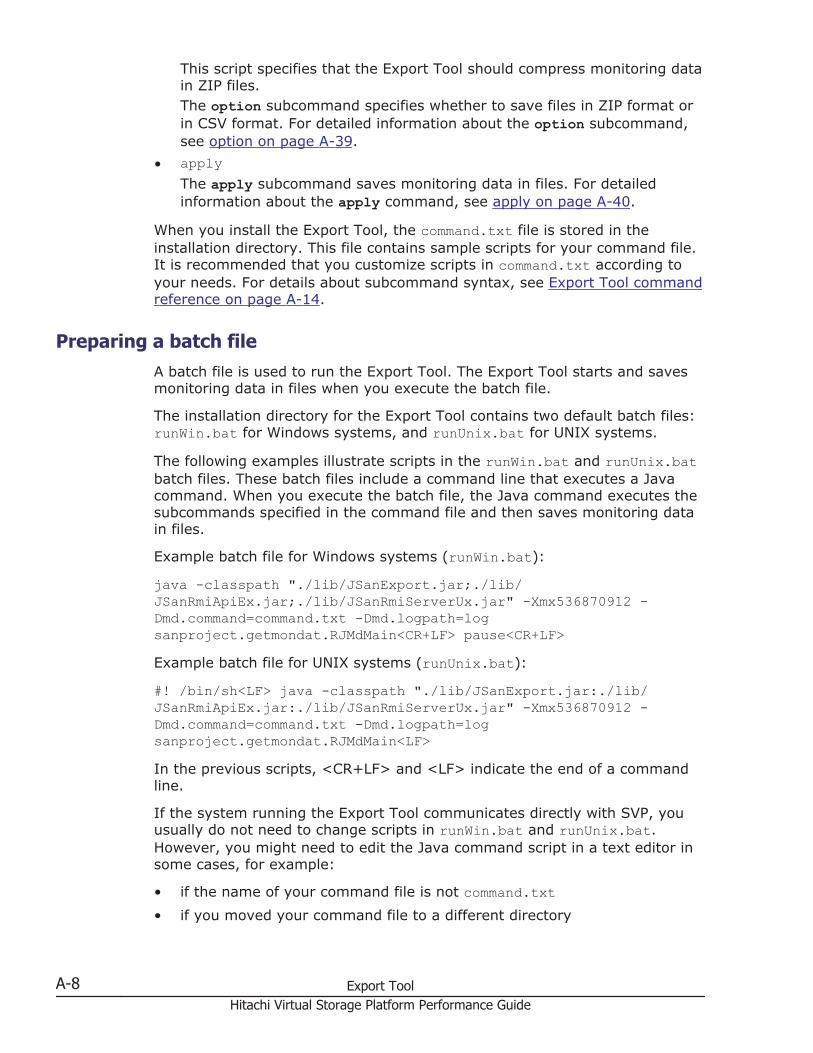
This script specifies that the Export Tool should compress monitoring datain ZIP files.The option subcommand specifies whether to save files in ZIP format orin CSV format. For detailed information about the option subcommand,see option on page A-39.
• applyThe apply subcommand saves monitoring data in files. For detailedinformation about the apply command, see apply on page A-40.
When you install the Export Tool, the command.txt file is stored in theinstallation directory. This file contains sample scripts for your command file.It is recommended that you customize scripts in command.txt according toyour needs. For details about subcommand syntax, see Export Tool commandreference on page A-14.
Preparing a batch fileA batch file is used to run the Export Tool. The Export Tool starts and savesmonitoring data in files when you execute the batch file.
The installation directory for the Export Tool contains two default batch files:runWin.bat for Windows systems, and runUnix.bat for UNIX systems.
The following examples illustrate scripts in the runWin.bat and runUnix.batbatch files. These batch files include a command line that executes a Javacommand. When you execute the batch file, the Java command executes thesubcommands specified in the command file and then saves monitoring datain files.
Example batch file for Windows systems (runWin.bat):
java -classpath "./lib/JSanExport.jar;./lib/JSanRmiApiEx.jar;./lib/JSanRmiServerUx.jar" -Xmx536870912 -Dmd.command=command.txt -Dmd.logpath=logsanproject.getmondat.RJMdMain<CR+LF> pause<CR+LF>Example batch file for UNIX systems (runUnix.bat):
#! /bin/sh<LF> java -classpath "./lib/JSanExport.jar:./lib/JSanRmiApiEx.jar:./lib/JSanRmiServerUx.jar" -Xmx536870912 -Dmd.command=command.txt -Dmd.logpath=logsanproject.getmondat.RJMdMain<LF>In the previous scripts, <CR+LF> and <LF> indicate the end of a commandline.
If the system running the Export Tool communicates directly with SVP, youusually do not need to change scripts in runWin.bat and runUnix.bat.However, you might need to edit the Java command script in a text editor insome cases, for example:
• if the name of your command file is not command.txt• if you moved your command file to a different directory
A-8 Export ToolHitachi Virtual Storage Platform Performance Guide
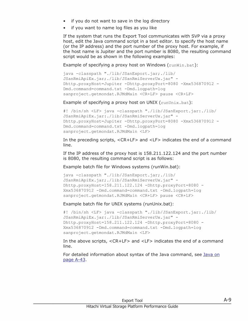
• if you do not want to save in the log directory• if you want to name log files as you like
If the system that runs the Export Tool communicates with SVP via a proxyhost, edit the Java command script in a text editor. to specify the host name(or the IP address) and the port number of the proxy host. For example, ifthe host name is Jupiter and the port number is 8080, the resulting commandscript would be as shown in the following examples:
Example of specifying a proxy host on Windows (runWin.bat):
java -classpath "./lib/JSanExport.jar;./lib/JSanRmiApiEx.jar;./lib/JSanRmiServerUx.jar" -Dhttp.proxyHost=Jupiter -Dhttp.proxyPort=8080 -Xmx536870912 -Dmd.command=command.txt -Dmd.logpath=logsanproject.getmondat.RJMdMain <CR+LF> pause <CR+LF>Example of specifying a proxy host on UNIX (runUnix.bat):
#! /bin/sh <LF> java -classpath "./lib/JSanExport.jar:./lib/JSanRmiApiEx.jar:./lib/JSanRmiServerUx.jar" -Dhttp.proxyHost=Jupiter -Dhttp.proxyPort=8080 -Xmx536870912 -Dmd.command=command.txt -Dmd.logpath=logsanproject.getmondat.RJMdMain <LF>In the preceding scripts, <CR+LF> and <LF> indicates the end of a commandline.
If the IP address of the proxy host is 158.211.122.124 and the port numberis 8080, the resulting command script is as follows:
Example batch file for Windows systems (runWin.bat):
java -classpath "./lib/JSanExport.jar;./lib/JSanRmiApiEx.jar;./lib/JSanRmiServerUx.jar" -Dhttp.proxyHost=158.211.122.124 -Dhttp.proxyPort=8080 -Xmx536870912 -Dmd.command=command.txt -Dmd.logpath=logsanproject.getmondat.RJMdMain <CR+LF> pause <CR+LF>Example batch file for UNIX systems (runUnix.bat):
#! /bin/sh <LF> java -classpath "./lib/JSanExport.jar:./lib/JSanRmiApiEx.jar:./lib/JSanRmiServerUx.jar" -Dhttp.proxyHost=158.211.122.124 -Dhttp.proxyPort=8080 -Xmx536870912 -Dmd.command=command.txt -Dmd.logpath=logsanproject.getmondat.RJMdMain <LF>In the above scripts, <CR+LF> and <LF> indicates the end of a commandline.
For detailed information about syntax of the Java command, see Java onpage A-43.
Export Tool A-9Hitachi Virtual Storage Platform Performance Guide
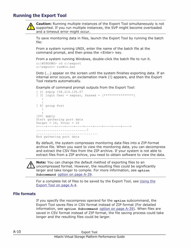
Running the Export Tool
Caution: Running multiple instances of the Export Tool simultaneously is notsupported. If you run multiple instances, the SVP might become overloadedand a timeout error might occur.
To save monitoring data in files, launch the Export Tool by running the batchfile:
From a system running UNIX, enter the name of the batch file at thecommand prompt, and then press the <Enter> key.
From a system running Windows, double-click the batch file to run it.c:\WINDOWS> cd c:\export c:\export> runWin.batDots (...) appear on the screen until the system finishes exporting data. If aninternal error occurs, an exclamation mark (!) appears, and then the ExportTool restarts automatically.
Example of command prompt outputs from the Export Tool:[ 2] svpip 158.214.135.57 [ 3] login User = expusr, Passwd = [****************] : :[ 6] group Port : :[20] apply Start gathering port data Target = 16, Total = 16+----+----+----+----+----+----+----+----+----+----+...........................! ................................. End gathering port data By default, the system compresses monitoring data files into a ZIP-formatarchive file. When you want to view the monitoring data, you can decompressand extract the CSV files from the ZIP archive. If your system is not able toextract files from a ZIP archive, you need to obtain software to view the data.
Note: You can change the default method of exporting files to anuncompressed format. However, the resulting files could be significantlylarger and take longer to compile. For more information, see optionSubcommand option on page A-39.
For a complete list of files to be saved by the Export Tool, see Using theExport Tool on page A-4.
File formats
If you specify the nocompress operand for the option subcommand, theExport Tool saves files in CSV format instead of ZIP format (For detailedinformation, see option Subcommand option on page A-39). When files aresaved in CSV format instead of ZIP format, the file saving process could takelonger and the resulting files could be larger.
A-10 Export ToolHitachi Virtual Storage Platform Performance Guide
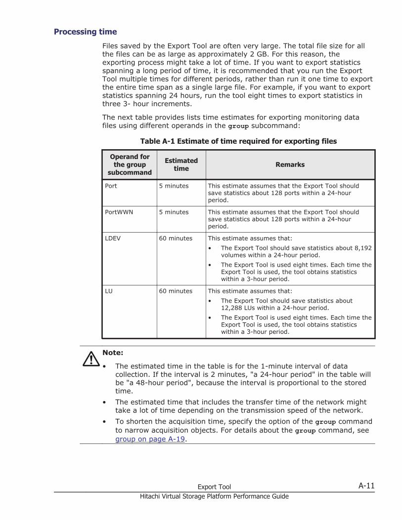
Processing time
Files saved by the Export Tool are often very large. The total file size for allthe files can be as large as approximately 2 GB. For this reason, theexporting process might take a lot of time. If you want to export statisticsspanning a long period of time, it is recommended that you run the ExportTool multiple times for different periods, rather than run it one time to exportthe entire time span as a single large file. For example, if you want to exportstatistics spanning 24 hours, run the tool eight times to export statistics inthree 3- hour increments.
The next table provides lists time estimates for exporting monitoring datafiles using different operands in the group subcommand:
Table A-1 Estimate of time required for exporting files
Operand forthe group
subcommand
Estimatedtime Remarks
Port 5 minutes This estimate assumes that the Export Tool shouldsave statistics about 128 ports within a 24-hourperiod.
PortWWN 5 minutes This estimate assumes that the Export Tool shouldsave statistics about 128 ports within a 24-hourperiod.
LDEV 60 minutes This estimate assumes that:• The Export Tool should save statistics about 8,192
volumes within a 24-hour period.• The Export Tool is used eight times. Each time the
Export Tool is used, the tool obtains statisticswithin a 3-hour period.
LU 60 minutes This estimate assumes that:• The Export Tool should save statistics about
12,288 LUs within a 24-hour period.• The Export Tool is used eight times. Each time the
Export Tool is used, the tool obtains statisticswithin a 3-hour period.
Note:
• The estimated time in the table is for the 1-minute interval of datacollection. If the interval is 2 minutes, "a 24-hour period" in the table willbe "a 48-hour period", because the interval is proportional to the storedtime.
• The estimated time that includes the transfer time of the network mighttake a lot of time depending on the transmission speed of the network.
• To shorten the acquisition time, specify the option of the group commandto narrow acquisition objects. For details about the group command, seegroup on page A-19.
Export Tool A-11Hitachi Virtual Storage Platform Performance Guide
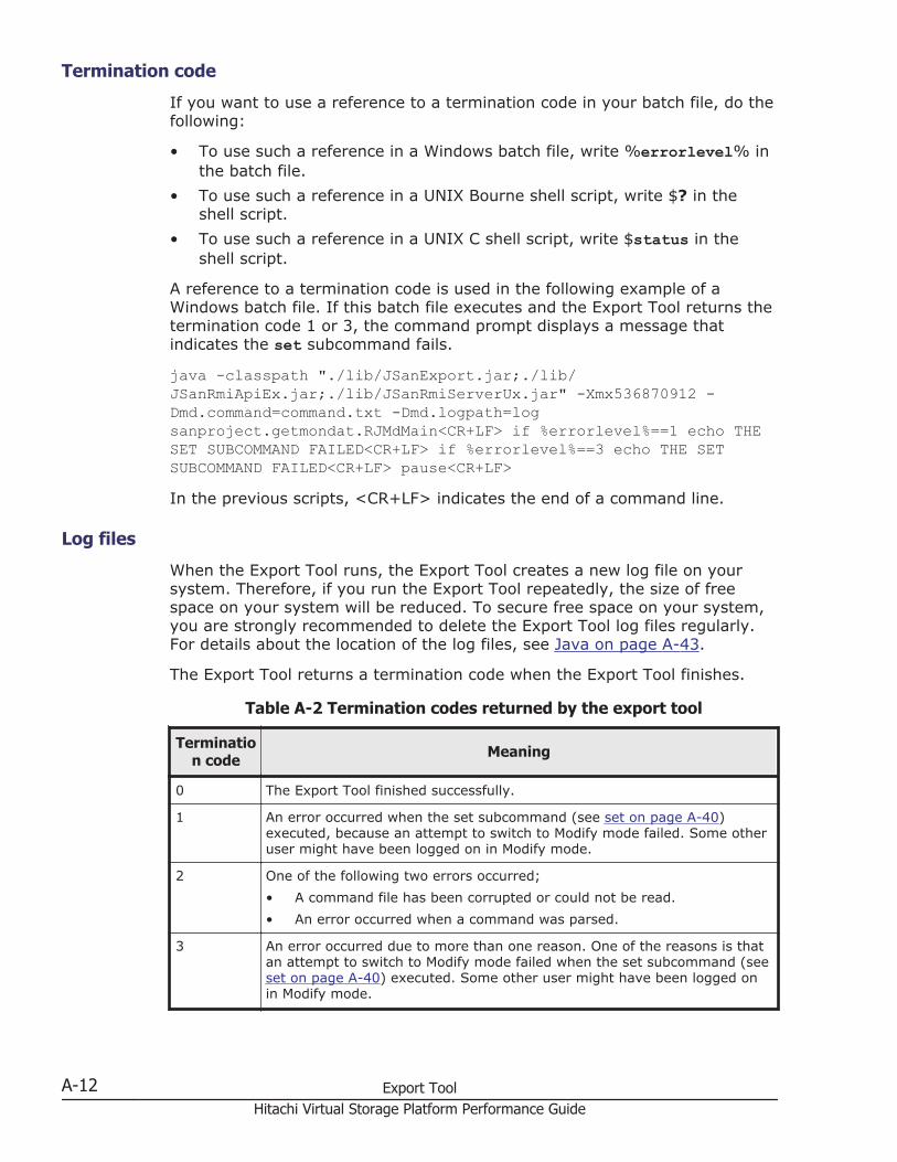
Termination code
If you want to use a reference to a termination code in your batch file, do thefollowing:
• To use such a reference in a Windows batch file, write %errorlevel% inthe batch file.
• To use such a reference in a UNIX Bourne shell script, write $? in theshell script.
• To use such a reference in a UNIX C shell script, write $status in theshell script.
A reference to a termination code is used in the following example of aWindows batch file. If this batch file executes and the Export Tool returns thetermination code 1 or 3, the command prompt displays a message thatindicates the set subcommand fails.
java -classpath "./lib/JSanExport.jar;./lib/JSanRmiApiEx.jar;./lib/JSanRmiServerUx.jar" -Xmx536870912 -Dmd.command=command.txt -Dmd.logpath=logsanproject.getmondat.RJMdMain<CR+LF> if %errorlevel%==1 echo THESET SUBCOMMAND FAILED<CR+LF> if %errorlevel%==3 echo THE SETSUBCOMMAND FAILED<CR+LF> pause<CR+LF>In the previous scripts, <CR+LF> indicates the end of a command line.
Log files
When the Export Tool runs, the Export Tool creates a new log file on yoursystem. Therefore, if you run the Export Tool repeatedly, the size of freespace on your system will be reduced. To secure free space on your system,you are strongly recommended to delete the Export Tool log files regularly.For details about the location of the log files, see Java on page A-43.
The Export Tool returns a termination code when the Export Tool finishes.
Table A-2 Termination codes returned by the export tool
Termination code Meaning
0 The Export Tool finished successfully.
1 An error occurred when the set subcommand (see set on page A-40)executed, because an attempt to switch to Modify mode failed. Some otheruser might have been logged on in Modify mode.
2 One of the following two errors occurred;• A command file has been corrupted or could not be read.• An error occurred when a command was parsed.
3 An error occurred due to more than one reason. One of the reasons is thatan attempt to switch to Modify mode failed when the set subcommand (seeset on page A-40) executed. Some other user might have been logged onin Modify mode.
A-12 Export ToolHitachi Virtual Storage Platform Performance Guide
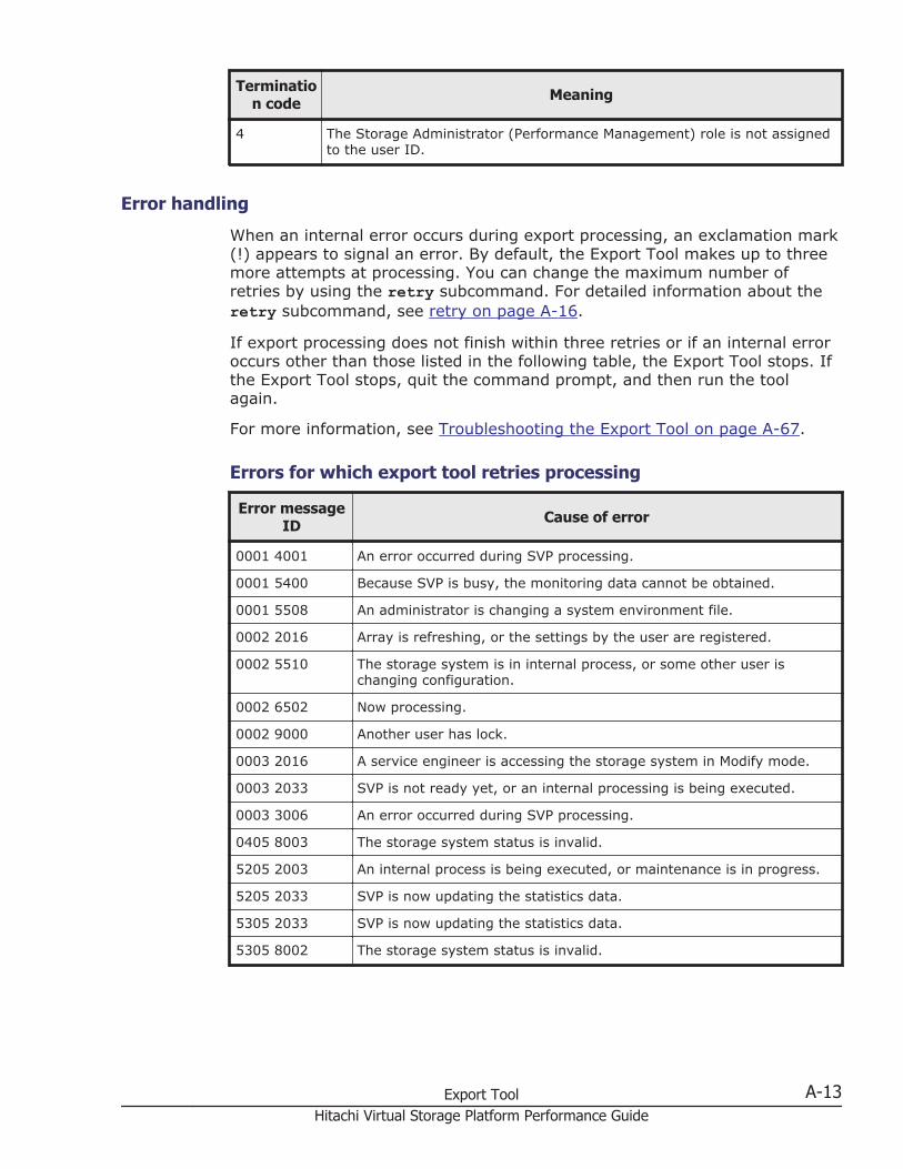
Termination code Meaning
4 The Storage Administrator (Performance Management) role is not assignedto the user ID.
Error handling
When an internal error occurs during export processing, an exclamation mark(!) appears to signal an error. By default, the Export Tool makes up to threemore attempts at processing. You can change the maximum number ofretries by using the retry subcommand. For detailed information about theretry subcommand, see retry on page A-16.
If export processing does not finish within three retries or if an internal erroroccurs other than those listed in the following table, the Export Tool stops. Ifthe Export Tool stops, quit the command prompt, and then run the toolagain.
For more information, see Troubleshooting the Export Tool on page A-67.
Errors for which export tool retries processing
Error messageID Cause of error
0001 4001 An error occurred during SVP processing.
0001 5400 Because SVP is busy, the monitoring data cannot be obtained.
0001 5508 An administrator is changing a system environment file.
0002 2016 Array is refreshing, or the settings by the user are registered.
0002 5510 The storage system is in internal process, or some other user ischanging configuration.
0002 6502 Now processing.
0002 9000 Another user has lock.
0003 2016 A service engineer is accessing the storage system in Modify mode.
0003 2033 SVP is not ready yet, or an internal processing is being executed.
0003 3006 An error occurred during SVP processing.
0405 8003 The storage system status is invalid.
5205 2003 An internal process is being executed, or maintenance is in progress.
5205 2033 SVP is now updating the statistics data.
5305 2033 SVP is now updating the statistics data.
5305 8002 The storage system status is invalid.
Export Tool A-13Hitachi Virtual Storage Platform Performance Guide
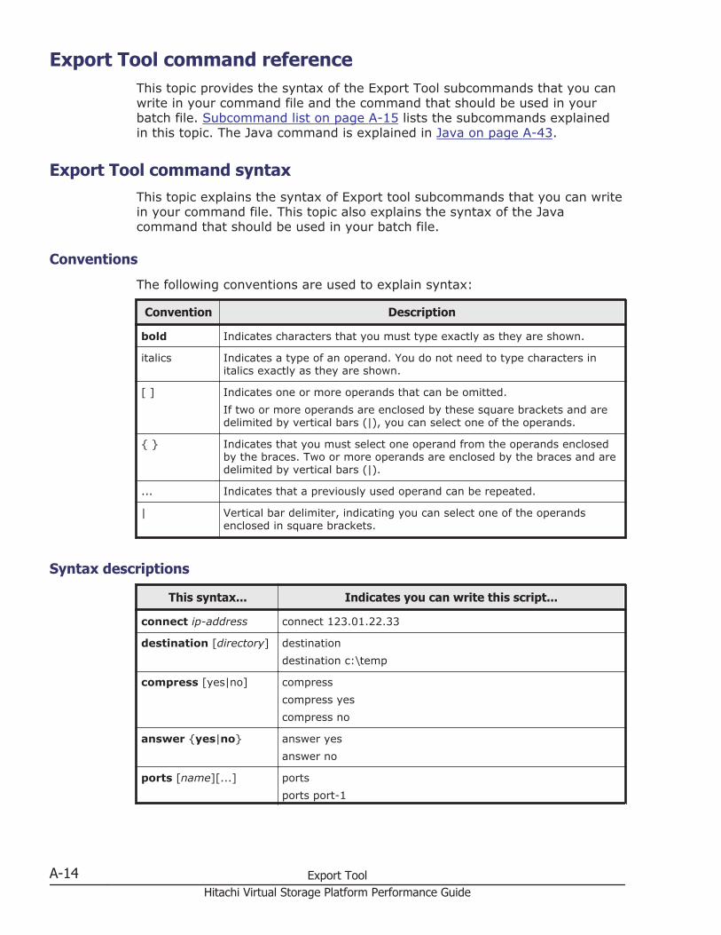
Export Tool command referenceThis topic provides the syntax of the Export Tool subcommands that you canwrite in your command file and the command that should be used in yourbatch file. Subcommand list on page A-15 lists the subcommands explainedin this topic. The Java command is explained in Java on page A-43.
Export Tool command syntaxThis topic explains the syntax of Export tool subcommands that you can writein your command file. This topic also explains the syntax of the Javacommand that should be used in your batch file.
Conventions
The following conventions are used to explain syntax:
Convention Description
bold Indicates characters that you must type exactly as they are shown.
italics Indicates a type of an operand. You do not need to type characters initalics exactly as they are shown.
[ ] Indicates one or more operands that can be omitted.If two or more operands are enclosed by these square brackets and aredelimited by vertical bars (|), you can select one of the operands.
{ } Indicates that you must select one operand from the operands enclosedby the braces. Two or more operands are enclosed by the braces and aredelimited by vertical bars (|).
... Indicates that a previously used operand can be repeated.
| Vertical bar delimiter, indicating you can select one of the operandsenclosed in square brackets.
Syntax descriptions
This syntax... Indicates you can write this script...
connect ip-address connect 123.01.22.33
destination [directory] destinationdestination c:\temp
compress [yes|no] compresscompress yescompress no
answer {yes|no} answer yesanswer no
ports [name][...] portsports port-1
A-14 Export ToolHitachi Virtual Storage Platform Performance Guide
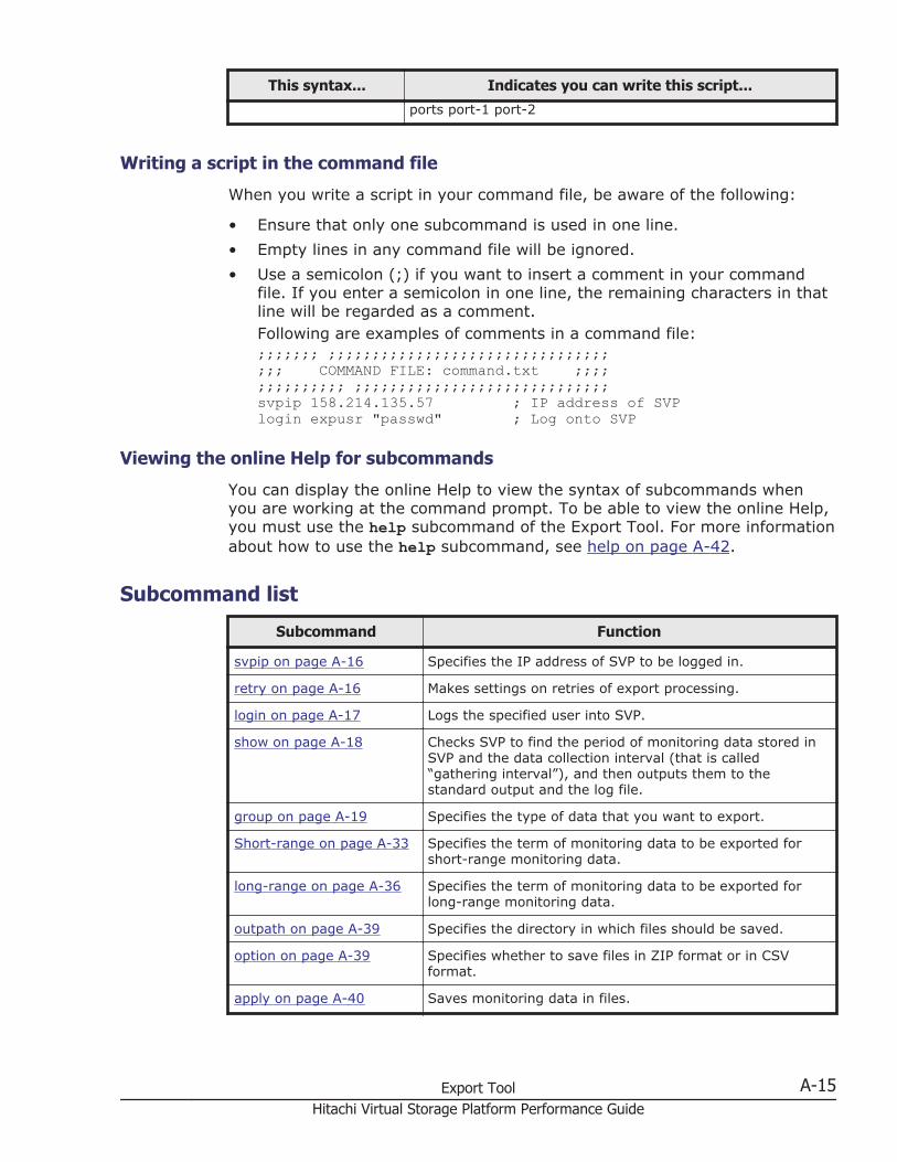
This syntax... Indicates you can write this script...
ports port-1 port-2
Writing a script in the command file
When you write a script in your command file, be aware of the following:
• Ensure that only one subcommand is used in one line.• Empty lines in any command file will be ignored.• Use a semicolon (;) if you want to insert a comment in your command
file. If you enter a semicolon in one line, the remaining characters in thatline will be regarded as a comment.Following are examples of comments in a command file:;;;;;;; ;;;;;;;;;;;;;;;;;;;;;;;;;;;;;;;;;;; COMMAND FILE: command.txt ;;;;;;;;;;;;;; ;;;;;;;;;;;;;;;;;;;;;;;;;;;;;svpip 158.214.135.57 ; IP address of SVPlogin expusr "passwd" ; Log onto SVP
Viewing the online Help for subcommands
You can display the online Help to view the syntax of subcommands whenyou are working at the command prompt. To be able to view the online Help,you must use the help subcommand of the Export Tool. For more informationabout how to use the help subcommand, see help on page A-42.
Subcommand list
Subcommand Function
svpip on page A-16 Specifies the IP address of SVP to be logged in.
retry on page A-16 Makes settings on retries of export processing.
login on page A-17 Logs the specified user into SVP.
show on page A-18 Checks SVP to find the period of monitoring data stored inSVP and the data collection interval (that is called“gathering interval”), and then outputs them to thestandard output and the log file.
group on page A-19 Specifies the type of data that you want to export.
Short-range on page A-33 Specifies the term of monitoring data to be exported forshort-range monitoring data.
long-range on page A-36 Specifies the term of monitoring data to be exported forlong-range monitoring data.
outpath on page A-39 Specifies the directory in which files should be saved.
option on page A-39 Specifies whether to save files in ZIP format or in CSVformat.
apply on page A-40 Saves monitoring data in files.
Export Tool A-15Hitachi Virtual Storage Platform Performance Guide
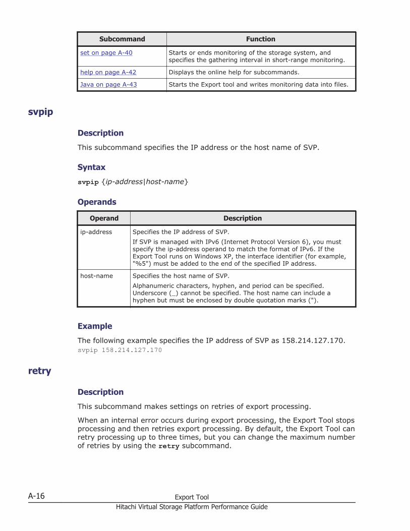
Subcommand Function
set on page A-40 Starts or ends monitoring of the storage system, andspecifies the gathering interval in short-range monitoring.
help on page A-42 Displays the online help for subcommands.
Java on page A-43 Starts the Export tool and writes monitoring data into files.
svpip
Description
This subcommand specifies the IP address or the host name of SVP.
Syntax
svpip {ip-address|host-name}
Operands
Operand Description
ip-address Specifies the IP address of SVP.If SVP is managed with IPv6 (Internet Protocol Version 6), you mustspecify the ip-address operand to match the format of IPv6. If theExport Tool runs on Windows XP, the interface identifier (for example,"%5") must be added to the end of the specified IP address.
host-name Specifies the host name of SVP.Alphanumeric characters, hyphen, and period can be specified.Underscore (_) cannot be specified. The host name can include ahyphen but must be enclosed by double quotation marks (").
Example
The following example specifies the IP address of SVP as 158.214.127.170.svpip 158.214.127.170
retry
Description
This subcommand makes settings on retries of export processing.
When an internal error occurs during export processing, the Export Tool stopsprocessing and then retries export processing. By default, the Export Tool canretry processing up to three times, but you can change the maximum numberof retries by using the retry subcommand.
A-16 Export ToolHitachi Virtual Storage Platform Performance Guide
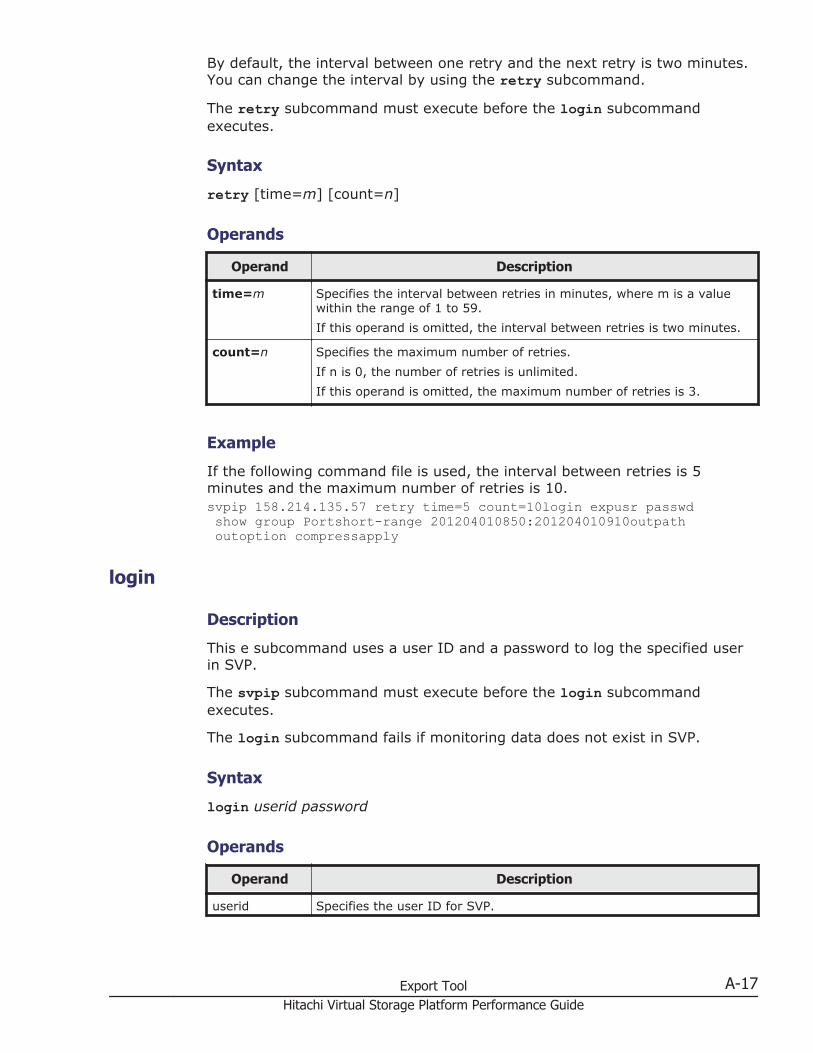
By default, the interval between one retry and the next retry is two minutes.You can change the interval by using the retry subcommand.
The retry subcommand must execute before the login subcommandexecutes.
Syntax
retry [time=m] [count=n]
Operands
Operand Description
time=m Specifies the interval between retries in minutes, where m is a valuewithin the range of 1 to 59.If this operand is omitted, the interval between retries is two minutes.
count=n Specifies the maximum number of retries.If n is 0, the number of retries is unlimited.If this operand is omitted, the maximum number of retries is 3.
Example
If the following command file is used, the interval between retries is 5minutes and the maximum number of retries is 10.svpip 158.214.135.57 retry time=5 count=10login expusr passwd show group Portshort-range 201204010850:201204010910outpath outoption compressapply
login
Description
This e subcommand uses a user ID and a password to log the specified userin SVP.
The svpip subcommand must execute before the login subcommandexecutes.
The login subcommand fails if monitoring data does not exist in SVP.
Syntax
login userid password
Operands
Operand Description
userid Specifies the user ID for SVP.
Export Tool A-17Hitachi Virtual Storage Platform Performance Guide

Operand Description
If the user ID includes any non-alphanumeric character, the user IDmust be enclosed by double quotation marks (").Be sure to specify a user ID that should be used exclusively with theExport Tool. For detailed information, see System requirements on pageA-3.
password Specifies the password of the user.If the password includes any non-alphanumeric character, the passwordID must be enclosed by double quotation marks (").
Example
This example logs the user expusr into SVP whose IP address is158.214.127.170. The password is pswd.svpip 158.214.127.170 login expuser pswd
show
Description
This subcommand outputs the following information to the standard output(for example, to the command prompt):
• the period during which monitoring data was collected onto SVP (storingperiod)
• the interval at which the monitoring data was collected (gatheringinterval)
Performance Monitor collects statistics by the two types of storing periods: inshort range and in long range. In short-range monitoring, the monitoringdata between 8 hours and 15 days is stored in SVP, and in long-rangemonitoring, the monitoring data up to 3 months is stored in SVP. For detailson the two storing periods, see Short-range on page A-33 and long-rangeon page A-36.
Storing periods output by the show subcommand are the same as theinformation displayed in the Monitoring Term area of the MonitorPerformance window.
Figure A-1 The monitoring term area
A-18 Export ToolHitachi Virtual Storage Platform Performance Guide
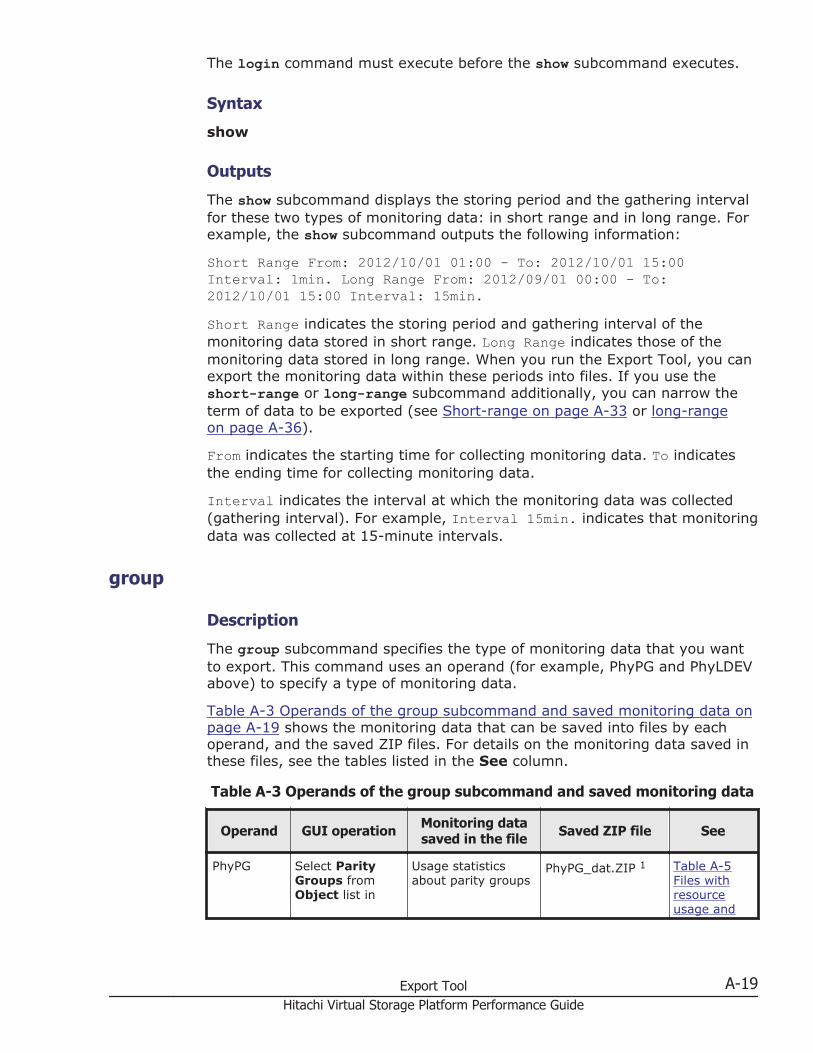
The login command must execute before the show subcommand executes.
Syntax
show
Outputs
The show subcommand displays the storing period and the gathering intervalfor these two types of monitoring data: in short range and in long range. Forexample, the show subcommand outputs the following information:
Short Range From: 2012/10/01 01:00 - To: 2012/10/01 15:00Interval: 1min. Long Range From: 2012/09/01 00:00 - To:2012/10/01 15:00 Interval: 15min.Short Range indicates the storing period and gathering interval of themonitoring data stored in short range. Long Range indicates those of themonitoring data stored in long range. When you run the Export Tool, you canexport the monitoring data within these periods into files. If you use theshort-range or long-range subcommand additionally, you can narrow theterm of data to be exported (see Short-range on page A-33 or long-rangeon page A-36).
From indicates the starting time for collecting monitoring data. To indicatesthe ending time for collecting monitoring data.
Interval indicates the interval at which the monitoring data was collected(gathering interval). For example, Interval 15min. indicates that monitoringdata was collected at 15-minute intervals.
group
Description
The group subcommand specifies the type of monitoring data that you wantto export. This command uses an operand (for example, PhyPG and PhyLDEVabove) to specify a type of monitoring data.
Table A-3 Operands of the group subcommand and saved monitoring data onpage A-19 shows the monitoring data that can be saved into files by eachoperand, and the saved ZIP files. For details on the monitoring data saved inthese files, see the tables listed in the See column.
Table A-3 Operands of the group subcommand and saved monitoring data
Operand GUI operation Monitoring datasaved in the file Saved ZIP file See
PhyPG Select ParityGroups fromObject list in
Usage statisticsabout parity groups
PhyPG_dat.ZIP 1 Table A-5Files withresourceusage and
Export Tool A-19Hitachi Virtual Storage Platform Performance Guide
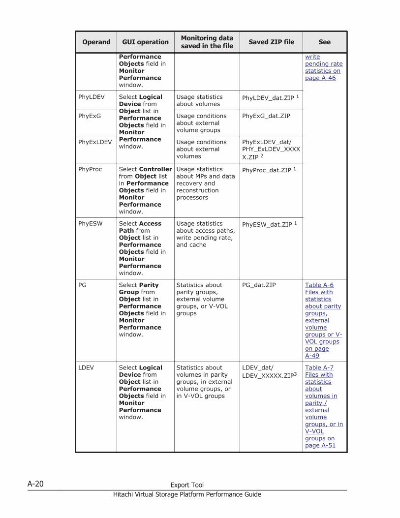
Operand GUI operation Monitoring datasaved in the file Saved ZIP file See
PerformanceObjects field inMonitorPerformancewindow.
writepending ratestatistics onpage A-46
PhyLDEV Select LogicalDevice fromObject list inPerformanceObjects field inMonitorPerformancewindow.
Usage statisticsabout volumes
PhyLDEV_dat.ZIP 1
PhyExG Usage conditionsabout externalvolume groups
PhyExG_dat.ZIP
PhyExLDEV Usage conditionsabout externalvolumes
PhyExLDEV_dat/PHY_ExLDEV_XXXXX.ZIP 2
PhyProc Select Controllerfrom Object listin PerformanceObjects field inMonitorPerformancewindow.
Usage statisticsabout MPs and datarecovery andreconstructionprocessors
PhyProc_dat.ZIP 1
PhyESW Select AccessPath fromObject list inPerformanceObjects field inMonitorPerformancewindow.
Usage statisticsabout access paths,write pending rate,and cache
PhyESW_dat.ZIP 1
PG Select ParityGroup fromObject list inPerformanceObjects field inMonitorPerformancewindow.
Statistics aboutparity groups,external volumegroups, or V-VOLgroups
PG_dat.ZIP Table A-6Files withstatisticsabout paritygroups,externalvolumegroups or V-VOL groupson pageA-49
LDEV Select LogicalDevice fromObject list inPerformanceObjects field inMonitorPerformancewindow.
Statistics aboutvolumes in paritygroups, in externalvolume groups, orin V-VOL groups
LDEV_dat/LDEV_XXXXX.ZIP3
Table A-7Files withstatisticsaboutvolumes inparity /externalvolumegroups, or inV-VOLgroups onpage A-51
A-20 Export ToolHitachi Virtual Storage Platform Performance Guide
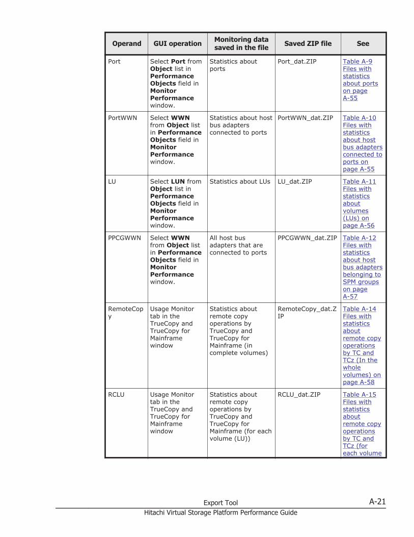
Operand GUI operation Monitoring datasaved in the file Saved ZIP file See
Port Select Port fromObject list inPerformanceObjects field inMonitorPerformancewindow.
Statistics aboutports
Port_dat.ZIP Table A-9Files withstatisticsabout portson pageA-55
PortWWN Select WWNfrom Object listin PerformanceObjects field inMonitorPerformancewindow.
Statistics about hostbus adaptersconnected to ports
PortWWN_dat.ZIP Table A-10Files withstatisticsabout hostbus adaptersconnected toports onpage A-55
LU Select LUN fromObject list inPerformanceObjects field inMonitorPerformancewindow.
Statistics about LUs LU_dat.ZIP Table A-11Files withstatisticsaboutvolumes(LUs) onpage A-56
PPCGWWN Select WWNfrom Object listin PerformanceObjects field inMonitorPerformancewindow.
All host busadapters that areconnected to ports
PPCGWWN_dat.ZIP Table A-12Files withstatisticsabout hostbus adaptersbelonging toSPM groupson pageA-57
RemoteCopy
Usage Monitortab in theTrueCopy andTrueCopy forMainframewindow
Statistics aboutremote copyoperations byTrueCopy andTrueCopy forMainframe (incomplete volumes)
RemoteCopy_dat.ZIP
Table A-14Files withstatisticsaboutremote copyoperationsby TC andTCz (In thewholevolumes) onpage A-58
RCLU Usage Monitortab in theTrueCopy andTrueCopy forMainframewindow
Statistics aboutremote copyoperations byTrueCopy andTrueCopy forMainframe (for eachvolume (LU))
RCLU_dat.ZIP Table A-15Files withstatisticsaboutremote copyoperationsby TC andTCz (foreach volume
Export Tool A-21Hitachi Virtual Storage Platform Performance Guide
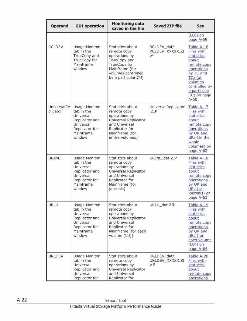
Operand GUI operation Monitoring datasaved in the file Saved ZIP file See
(LU)) onpage A-59
RCLDEV Usage Monitortab in theTrueCopy andTrueCopy forMainframewindow
Statistics aboutremote copyoperations byTrueCopy andTrueCopy forMainframe (forvolumes controlledby a particular CU)
RCLDEV_dat/RCLDEV_XXXXX.ZIP4
Table A-16Files withstatisticsaboutremote copyoperationsby TC andTCz (atvolumescontrolled bya particularCU) on pageA-60
UniversalReplicator
Usage Monitortab in theUniversalReplicator andUniversalReplicator forMainframewindow
Statistics aboutremote copyoperations byUniversal Replicatorand UniversalReplicator forMainframe (forentire volumes)
UniversalReplicator.ZIP
Table A-17Files withstatisticsaboutremote copyoperationsby UR andURz (In thewholevolumes) onpage A-62
URJNL Usage Monitortab in theUniversalReplicator andUniversalReplicator forMainframewindow
Statistics aboutremote copyoperations byUniversal Replicatorand UniversalReplicator forMainframe (forjournals)
URJNL_dat.ZIP Table A-18Files withstatisticsaboutremote copyoperationsby UR andURz (atjournals) onpage A-63
URLU Usage Monitortab in theUniversalReplicator andUniversalReplicator forMainframewindow
Statistics aboutremote copyoperations byUniversal Replicatorand UniversalReplicator forMainframe (for eachvolume (LU))
URLU_dat.ZIP Table A-19Files withstatisticsaboutremote copyoperationsby UR andURz (foreach volume(LU)) onpage A-64
URLDEV Usage Monitortab in theUniversalReplicator andUniversalReplicator for
Statistics aboutremote copyoperations byUniversal Replicatorand UniversalReplicator for
URLDEV_dat/URLDEV_XXXXX.ZIP 5
Table A-20Files withstatisticsaboutremote copyoperations
A-22 Export ToolHitachi Virtual Storage Platform Performance Guide
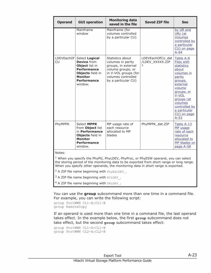
Operand GUI operation Monitoring datasaved in the file Saved ZIP file See
Mainframewindow
Mainframe (forvolumes controlledby a particular CU)
by UR andURz (atVolumescontrolled bya particularCU) on pageA-64
LDEVEachOfCU
Select LogicalDevice fromObject list inPerformanceObjects field inMonitorPerformancewindow.
Statistics aboutvolumes in paritygroups, in externalvolume groups, orin V-VOL groups (forvolumes controlledby a particular CU)
LDEVEachOfCU_dat/LDEV_XXXXX.ZIP3
Table A-8Files withstatisticsaboutvolumes inparitygroups,externalvolumegroups, orV-VOLgroups (atvolumescontrolled bya particularCU) on pageA-53
PhyMPPK Select MPPKfrom Object listin PerformanceObjects field inMonitorPerformancewindow.
MP usage rate ofeach resourceallocated to MPblades
PhyMPPK_dat.ZIP Table A-13MP usagerate of eachresourceallocated toMP blades onpage A-58
Notes:1 When you specify the PhyPG, PhyLDEV, PhyProc, or PhyESW operand, you can selectthe storing period of the monitoring data to be exported from short range or long range.When you specify other operands, the monitoring data in short range is exported.2 A ZIP file name beginning with PhyExLDEV_.3 A ZIP file name beginning with RCLDEV_.4 A ZIP file name beginning with URLDEV_.
You can use the group subcommand more than one time in a command file.For example, you can write the following script:group PortWWN CL1-A:CL1-Bgroup RemoteCopyIf an operand is used more than one time in a command file, the last operandtakes effect. In the example below, the first group subcommand does nottake effect, but the second group subcommand takes effect:group PortWWN CL1-A:CL1-Bgroup PortWWN CL2-A:CL2-B
Export Tool A-23Hitachi Virtual Storage Platform Performance Guide
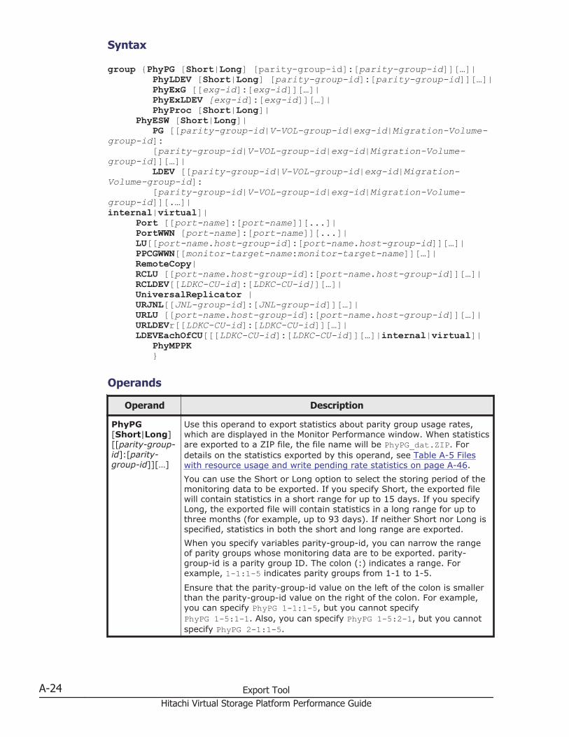
Syntax
group {PhyPG [Short|Long] [parity-group-id]:[parity-group-id]][…]| PhyLDEV [Short|Long] [parity-group-id]:[parity-group-id]][…]| PhyExG [[exg-id]:[exg-id]][…]| PhyExLDEV [exg-id]:[exg-id]][…]| PhyProc [Short|Long]| PhyESW [Short|Long]| PG [[parity-group-id|V-VOL-group-id|exg-id|Migration-Volume-group-id]: [parity-group-id|V-VOL-group-id|exg-id|Migration-Volume-group-id]][…]| LDEV [[parity-group-id|V-VOL-group-id|exg-id|Migration-Volume-group-id]: [parity-group-id|V-VOL-group-id|exg-id|Migration-Volume-group-id]][.…]|internal|virtual]| Port [[port-name]:[port-name]][...]| PortWWN [port-name]:[port-name]][...]| LU[[port-name.host-group-id]:[port-name.host-group-id]][…]| PPCGWWN[[monitor-target-name:monitor-target-name]][…]| RemoteCopy| RCLU [[port-name.host-group-id]:[port-name.host-group-id]][…]| RCLDEV[[LDKC-CU-id]:[LDKC-CU-id]][…]| UniversalReplicator | URJNL[[JNL-group-id]:[JNL-group-id]][…]| URLU [[port-name.host-group-id]:[port-name.host-group-id]][…]| URLDEVr[[LDKC-CU-id]:[LDKC-CU-id]][…]| LDEVEachOfCU[[[LDKC-CU-id]:[LDKC-CU-id]][…]|internal|virtual]| PhyMPPK }
Operands
Operand Description
PhyPG[Short|Long][[parity-group-id]:[parity-group-id]][…]
Use this operand to export statistics about parity group usage rates,which are displayed in the Monitor Performance window. When statisticsare exported to a ZIP file, the file name will be PhyPG_dat.ZIP. Fordetails on the statistics exported by this operand, see Table A-5 Fileswith resource usage and write pending rate statistics on page A-46.You can use the Short or Long option to select the storing period of themonitoring data to be exported. If you specify Short, the exported filewill contain statistics in a short range for up to 15 days. If you specifyLong, the exported file will contain statistics in a long range for up tothree months (for example, up to 93 days). If neither Short nor Long isspecified, statistics in both the short and long range are exported.When you specify variables parity-group-id, you can narrow the rangeof parity groups whose monitoring data are to be exported. parity-group-id is a parity group ID. The colon (:) indicates a range. Forexample, 1-1:1-5 indicates parity groups from 1-1 to 1-5.
Ensure that the parity-group-id value on the left of the colon is smallerthan the parity-group-id value on the right of the colon. For example,you can specify PhyPG 1-1:1-5, but you cannot specifyPhyPG 1-5:1-1. Also, you can specify PhyPG 1-5:2-1, but you cannotspecify PhyPG 2-1:1-5.
A-24 Export ToolHitachi Virtual Storage Platform Performance Guide
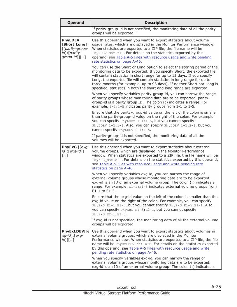
Operand Description
If parity-group-id is not specified, the monitoring data of all the paritygroups will be exported.
PhyLDEV[Short|Long][[parity-group-id]:[parity-group-id]][…]
Use this operand when you want to export statistics about volumeusage rates, which are displayed in the Monitor Performance window.When statistics are exported to a ZIP file, the file name will bePhyLDEV_dat.ZIP. For details on the statistics exported by thisoperand, see Table A-5 Files with resource usage and write pendingrate statistics on page A-46.You can use the Short or Long option to select the storing period of themonitoring data to be exported. If you specify Short, the exported filewill contain statistics in short range for up to 15 days. If you specifyLong, the exported file will contain statistics in long range for up tothree months (for example, up to 93 days). If neither Short nor Long isspecified, statistics in both the short and long range are exported.When you specify variables parity-group-id, you can narrow the rangeof parity groups whose monitoring data are to be exported. parity-group-id is a parity group ID. The colon (:) indicates a range. Forexample, 1-1:1-5 indicates parity groups from 1-1 to 1-5.
Ensure that the parity-group-id value on the left of the colon is smallerthan the parity-group-id value on the right of the colon. For example,you can specify PhyLDEV 1-1:1-5, but you cannot specifyPhyLDEV 1-5:1-1. Also, you can specify PhyLDEV 1-5:2-1, but youcannot specify PhyLDEV 2-1:1-5.
If parity-group-id is not specified, the monitoring data of all thevolumes will be exported.
PhyExG [[exg-id]:[exg-id]][…]
Use this operand when you want to export statistics about externalvolume groups, which are displayed in the Monitor Performancewindow. When statistics are exported to a ZIP file, the file name will bePhyExG_dat.ZIP. For details on the statistics exported by this operand,see Table A-5 Files with resource usage and write pending ratestatistics on page A-46.When you specify variables exg-id, you can narrow the range ofexternal volume groups whose monitoring data are to be exported.exg-id is an ID of an external volume group. The colon (:) indicates arange. For example, E1-1:E1-5 indicates external volume groups fromE1-1 to E1-5.Ensure that the exg-id value on the left of the colon is smaller than theexg-id value on the right of the colon. For example, you can specifyPhyExG E1-1:E1-5, but you cannot specify PhyExG E1-5:E1-1. Also,you can specify PhyExG E1-5:E2-1, but you cannot specifyPhyExG E2-1:E1-5.
If exg-id is not specified, the monitoring data of all the external volumegroups will be exported.
PhyExLDEV[[exg-id]:[exg-id]][…]
Use this operand when you want to export statistics about volumes inexternal volume groups, which are displayed in the MonitorPerformance window. When statistics are exported to a ZIP file, the filename will be PhyExLDEV_dat.ZIP. For details on the statistics exportedby this operand, see Table A-5 Files with resource usage and writepending rate statistics on page A-46.When you specify variables exg-id, you can narrow the range ofexternal volume groups whose monitoring data are to be exported.exg-id is an ID of an external volume group. The colon (:) indicates a
Export Tool A-25Hitachi Virtual Storage Platform Performance Guide
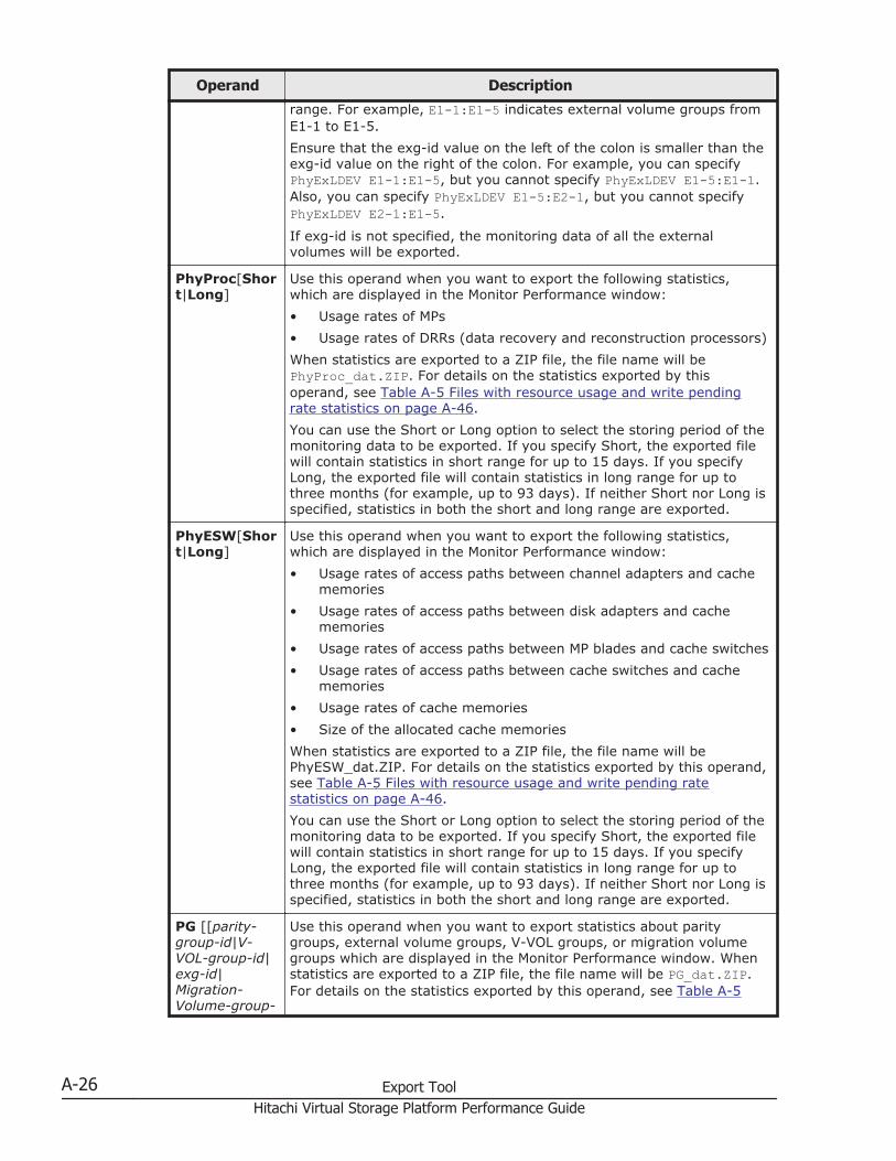
Operand Description
range. For example, E1-1:E1-5 indicates external volume groups fromE1-1 to E1-5.Ensure that the exg-id value on the left of the colon is smaller than theexg-id value on the right of the colon. For example, you can specifyPhyExLDEV E1-1:E1-5, but you cannot specify PhyExLDEV E1-5:E1-1.Also, you can specify PhyExLDEV E1-5:E2-1, but you cannot specifyPhyExLDEV E2-1:E1-5.
If exg-id is not specified, the monitoring data of all the externalvolumes will be exported.
PhyProc[Short|Long]
Use this operand when you want to export the following statistics,which are displayed in the Monitor Performance window:• Usage rates of MPs• Usage rates of DRRs (data recovery and reconstruction processors)When statistics are exported to a ZIP file, the file name will bePhyProc_dat.ZIP. For details on the statistics exported by thisoperand, see Table A-5 Files with resource usage and write pendingrate statistics on page A-46.You can use the Short or Long option to select the storing period of themonitoring data to be exported. If you specify Short, the exported filewill contain statistics in short range for up to 15 days. If you specifyLong, the exported file will contain statistics in long range for up tothree months (for example, up to 93 days). If neither Short nor Long isspecified, statistics in both the short and long range are exported.
PhyESW[Short|Long]
Use this operand when you want to export the following statistics,which are displayed in the Monitor Performance window:• Usage rates of access paths between channel adapters and cache
memories• Usage rates of access paths between disk adapters and cache
memories• Usage rates of access paths between MP blades and cache switches• Usage rates of access paths between cache switches and cache
memories• Usage rates of cache memories• Size of the allocated cache memoriesWhen statistics are exported to a ZIP file, the file name will bePhyESW_dat.ZIP. For details on the statistics exported by this operand,see Table A-5 Files with resource usage and write pending ratestatistics on page A-46.You can use the Short or Long option to select the storing period of themonitoring data to be exported. If you specify Short, the exported filewill contain statistics in short range for up to 15 days. If you specifyLong, the exported file will contain statistics in long range for up tothree months (for example, up to 93 days). If neither Short nor Long isspecified, statistics in both the short and long range are exported.
PG [[parity-group-id|V-VOL-group-id|exg-id|Migration-Volume-group-
Use this operand when you want to export statistics about paritygroups, external volume groups, V-VOL groups, or migration volumegroups which are displayed in the Monitor Performance window. Whenstatistics are exported to a ZIP file, the file name will be PG_dat.ZIP.For details on the statistics exported by this operand, see Table A-5
A-26 Export ToolHitachi Virtual Storage Platform Performance Guide
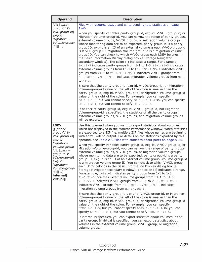
Operand Description
id]: [parity-group-id|V-VOL-group-id|exg-id|Migration-Volume-group-id]][…]
Files with resource usage and write pending rate statistics on pageA-46.When you specify variables parity-group-id, exg-id, V-VOL-group-id, orMigration-Volume-group-id, you can narrow the range of parity groups,external volume groups, V-VOL groups, or migration volume groups,whose monitoring data are to be exported. parity-group-id is a paritygroup ID. exg-id is an ID of an external volume group. V-VOL-group-idis V-VOL group ID. Migration-Volume-group-id is a migration volumegroup ID. You can check to which V-VOL group each LDEV belongs inthe Basic Information Display dialog box (a Storage Navigatorsecondary window). The colon (:) indicates a range. For example,1-1:1-5 indicates parity groups from 1-1 to 1-5. E1-1:E1-5 indicatesexternal volume groups from E1-1 to E1-5. V1-1:V5-1 indicates V-VOLgroups from V1-1 to V5-1. X1-1:X5-1 indicates V-VOL groups fromX1-1 to X5-1. M1-1:M5-1 indicates migration volume groups from M1-1to M5-1.
Ensure that the parity-group-id, exg-id, V-VOL-group-id, or Migration-Volume-group-id value on the left of the colon is smaller than theparity-group-id, exg-id, V-VOL-group-id, or Migration-Volume-group-idvalue on the right of the colon. For example, you can specifyPG 1-1:1-5, but you cannot specify PG 1-5:1-1. Also, you can specifyPG 1-5:2-1, but you cannot specify PG 2-1:1-5.
If neither of parity-group-id, exg-id, V-VOL-group-id, nor Migration-Volume-group-id is specified, the statistics of all the parity groups,external volume groups, V-VOL groups, and migration volume groupswill be exported.
LDEV[[[parity-group-id|V-VOL-group-id|exg-id|Migration-Volume-group-id]: [parity-group-id|V-VOL-group-id|exg-id|Migration-Volume-group-id]][…] |internal|virtual]|
Use this operand when you want to export statistics about volumes,which are displayed in the Monitor Performance window. When statisticsare exported to a ZIP file, multiple ZIP files whose names are beginningwith LDEV_ will be output. For details on the statistics exported by thisoperand, see Table A-9 Files with statistics about ports on page A-55.When you specify variables parity-group-id, exg-id, V-VOL-group-id, orMigration-Volume-group-id, you can narrow the range of parity groups,external volume groups, V-VOL groups, or migration volume groupswhose monitoring data are to be exported. parity-group-id is a paritygroup ID. exg-id is an ID of an external volume group.-volume-group-idis a migration volume group ID. You can check to which V-VOL groupeach LDEV belongs in the Basic Information Display dialog box (aStorage Navigator secondary window). The colon (:) indicates a range.For example, 1-1:1-5 indicates parity groups from 1-1 to 1-5.E1-1:E1-5 indicates external volume groups from E1-1 to E1-5.V1-1:V5-1 indicates V-VOL groups from V1-1 to V5-1. X1-1:X5-1indicates V-VOL groups from X1-1 to X5-1. M1-1:M5-1 indicatesmigration volume groups from M1-1 to M5-1.
Ensure that the parity-group-id-, exg-id, V-VOL-group-id, or Migration-Volume-group-id value on the left of the colon is smaller than theparity-group-id, exg-id, V-VOL-group-id, or Migration-Volume-group-idvalue on the right of the colon. For example, you can specifyLDEV 1-1:1-5, but you cannot specify LDEV 1-5:1-1. Also, you canspecify LDEV 1-5:2-1, but you cannot specify LDEV 2-1:1-5.
If internal is specified, you can export statistics about volumes in theparity group. If virtual is specified, you can export statistics aboutvolumes in the external volume group, V-VOL group, or migrationvolume group.
Export Tool A-27Hitachi Virtual Storage Platform Performance Guide
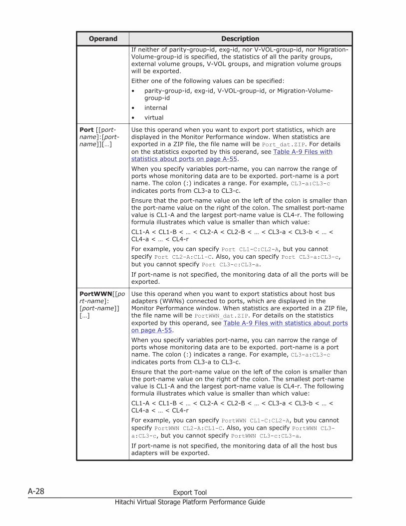
Operand Description
If neither of parity-group-id, exg-id, nor V-VOL-group-id, nor Migration-Volume-group-id is specified, the statistics of all the parity groups,external volume groups, V-VOL groups, and migration volume groupswill be exported.Either one of the following values can be specified:• parity-group-id, exg-id, V-VOL-group-id, or Migration-Volume-
group-id• internal• virtual
Port [[port-name]:[port-name]][…]
Use this operand when you want to export port statistics, which aredisplayed in the Monitor Performance window. When statistics areexported in a ZIP file, the file name will be Port_dat.ZIP. For detailson the statistics exported by this operand, see Table A-9 Files withstatistics about ports on page A-55.When you specify variables port-name, you can narrow the range ofports whose monitoring data are to be exported. port-name is a portname. The colon (:) indicates a range. For example, CL3-a:CL3-cindicates ports from CL3-a to CL3-c.Ensure that the port-name value on the left of the colon is smaller thanthe port-name value on the right of the colon. The smallest port-namevalue is CL1-A and the largest port-name value is CL4-r. The followingformula illustrates which value is smaller than which value:CL1-A < CL1-B < … < CL2-A < CL2-B < … < CL3-a < CL3-b < … <CL4-a < … < CL4-rFor example, you can specify Port CL1-C:CL2-A, but you cannotspecify Port CL2-A:CL1-C. Also, you can specify Port CL3-a:CL3-c,but you cannot specify Port CL3-c:CL3-a.
If port-name is not specified, the monitoring data of all the ports will beexported.
PortWWN[[port-name]:[port-name]][…]
Use this operand when you want to export statistics about host busadapters (WWNs) connected to ports, which are displayed in theMonitor Performance window. When statistics are exported in a ZIP file,the file name will be PortWWN_dat.ZIP. For details on the statisticsexported by this operand, see Table A-9 Files with statistics about portson page A-55.When you specify variables port-name, you can narrow the range ofports whose monitoring data are to be exported. port-name is a portname. The colon (:) indicates a range. For example, CL3-a:CL3-cindicates ports from CL3-a to CL3-c.Ensure that the port-name value on the left of the colon is smaller thanthe port-name value on the right of the colon. The smallest port-namevalue is CL1-A and the largest port-name value is CL4-r. The followingformula illustrates which value is smaller than which value:CL1-A < CL1-B < … < CL2-A < CL2-B < … < CL3-a < CL3-b < … <CL4-a < … < CL4-rFor example, you can specify PortWWN CL1-C:CL2-A, but you cannotspecify PortWWN CL2-A:CL1-C. Also, you can specify PortWWN CL3-a:CL3-c, but you cannot specify PortWWN CL3-c:CL3-a.
If port-name is not specified, the monitoring data of all the host busadapters will be exported.
A-28 Export ToolHitachi Virtual Storage Platform Performance Guide
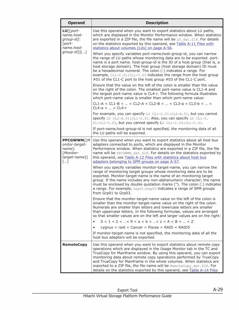
Operand Description
LU[[port-name.host-group-id]:[port-name.host-group-id]][…]
Use this operand when you want to export statistics about LU paths,which are displayed in the Monitor Performance window. When statisticsare exported in a ZIP file, the file name will be LU_dat.ZIP. For detailson the statistics exported by this operand, see Table A-11 Files withstatistics about volumes (LUs) on page A-56.When you specify variables port-name.host-group-id, you can narrowthe range of LU paths whose monitoring data are to be exported. port-name is a port name. host-group-id is the ID of a host group (that is, ahost storage domain). The host group (host storage domain) ID mustbe a hexadecimal numeral. The colon (:) indicates a range. Forexample, CL1-C.01:CL1-C.03 indicates the range from the host group#01 of the CL1-C port to the host group #03 of the CL1-C port.Ensure that the value on the left of the colon is smaller than the valueon the right of the colon. The smallest port-name value is CL1-A andthe largest port-name value is CL4-r. The following formula illustrateswhich port-name value is smaller than which port-name value:CL1-A < CL1-B < … < CL2-A < CL2-B < … < CL3-a < CL3-b < … <CL4-a < … < CL4-rFor example, you can specify LU CL1-C.01:CL2-A.01, but you cannotspecify LU CL2-A.01:CL1-C.01. Also, you can specify LU CL1-C.01:CL1-C.03, but you cannot specify LU CL1-C.03:CL1-C.01.
If port-name.host-group-id is not specified, the monitoring data of allthe LU paths will be exported.
PPCGWWN[[Monitor-target-name]:[Monitor-target-name]][…]
Use this operand when you want to export statistics about all host busadapters connected to ports, which are displayed in the MonitorPerformance window. When statistics are exported in a ZIP file, the filename will be PPCGWWN_dat.ZIP. For details on the statistics exported bythis operand, see Table A-12 Files with statistics about host busadapters belonging to SPM groups on page A-57.When you specify variables monitor-target-name, you can narrow therange of monitoring target groups whose monitoring data are to beexported. Monitor-target-name is the name of an monitoring targetgroup. If the name includes any non-alphanumeric character, the namemust be enclosed by double quotation marks ("). The colon (:) indicatesa range. For example, Grp01:Grp03 indicates a range of SPM groupsfrom Grp01 to Grp03.Ensure that the monitor-target-name value on the left of the colon issmaller than the monitor-target-name value on the right of the colon.Numerals are smaller than letters and lowercase letters are smallerthan uppercase letters. In the following formulae, values are arrangedso that smaller values are on the left and larger values are on the right:• 0 < 1 < 2 < …< 9 < a < b < …< z < A < B < … < Z• cygnus < raid < Cancer < Pisces < RAID < RAID5If monitor-target-name is not specified, the monitoring data of all thehost bus adapters will be exported.
RemoteCopy Use this operand when you want to export statistics about remote copyoperations which are displayed in the Usage Monitor tab in the TC andTrueCopy for Mainframe window. By using this operand, you can exportmonitoring data about remote copy operations performed by TrueCopyand TrueCopy for Mainframe in the whole volumes. When statistics areexported to a ZIP file, the file name will be RemoteCopy_dat.ZIP. Fordetails on the statistics exported by this operand, see Table A-14 Files
Export Tool A-29Hitachi Virtual Storage Platform Performance Guide
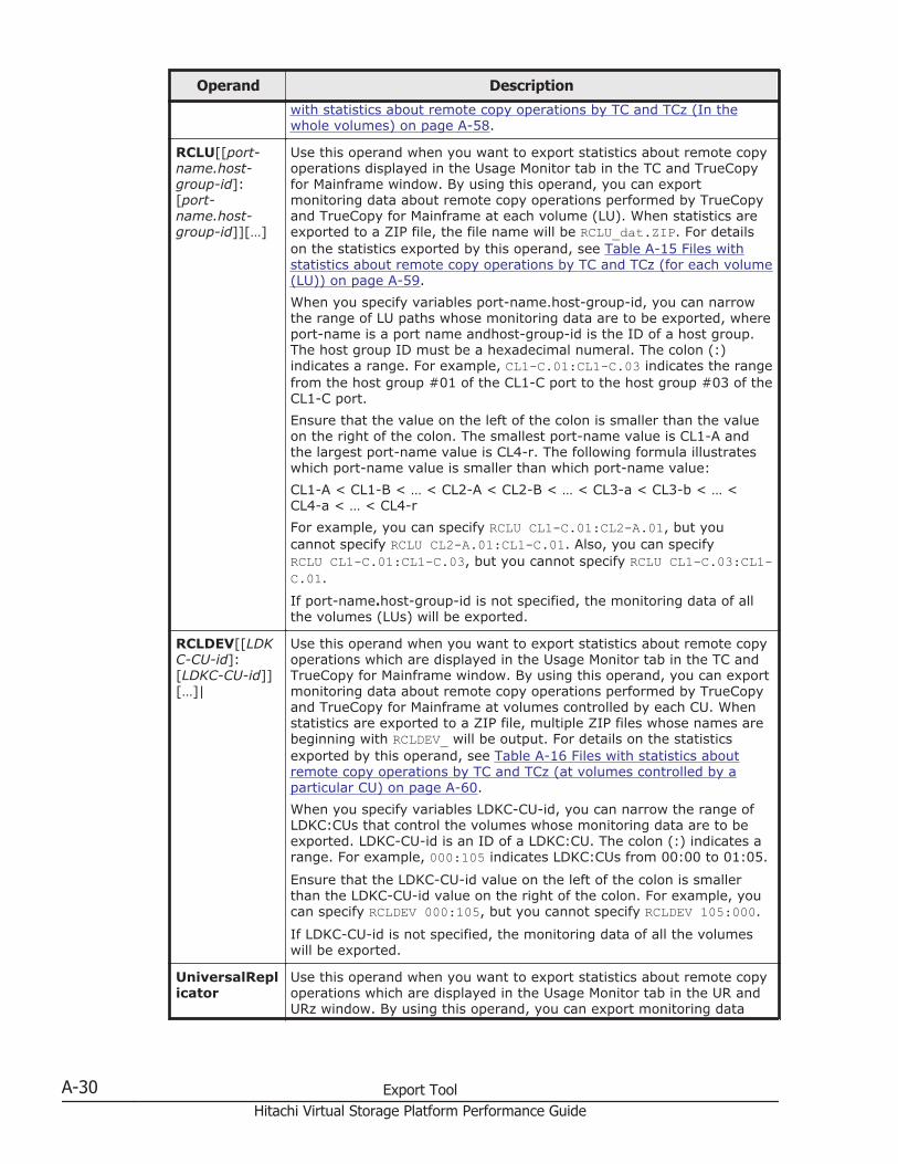
Operand Description
with statistics about remote copy operations by TC and TCz (In thewhole volumes) on page A-58.
RCLU[[port-name.host-group-id]:[port-name.host-group-id]][…]
Use this operand when you want to export statistics about remote copyoperations displayed in the Usage Monitor tab in the TC and TrueCopyfor Mainframe window. By using this operand, you can exportmonitoring data about remote copy operations performed by TrueCopyand TrueCopy for Mainframe at each volume (LU). When statistics areexported to a ZIP file, the file name will be RCLU_dat.ZIP. For detailson the statistics exported by this operand, see Table A-15 Files withstatistics about remote copy operations by TC and TCz (for each volume(LU)) on page A-59.When you specify variables port-name.host-group-id, you can narrowthe range of LU paths whose monitoring data are to be exported, whereport-name is a port name andhost-group-id is the ID of a host group.The host group ID must be a hexadecimal numeral. The colon (:)indicates a range. For example, CL1-C.01:CL1-C.03 indicates the rangefrom the host group #01 of the CL1-C port to the host group #03 of theCL1-C port.Ensure that the value on the left of the colon is smaller than the valueon the right of the colon. The smallest port-name value is CL1-A andthe largest port-name value is CL4-r. The following formula illustrateswhich port-name value is smaller than which port-name value:CL1-A < CL1-B < … < CL2-A < CL2-B < … < CL3-a < CL3-b < … <CL4-a < … < CL4-rFor example, you can specify RCLU CL1-C.01:CL2-A.01, but youcannot specify RCLU CL2-A.01:CL1-C.01. Also, you can specifyRCLU CL1-C.01:CL1-C.03, but you cannot specify RCLU CL1-C.03:CL1-C.01.
If port-name.host-group-id is not specified, the monitoring data of allthe volumes (LUs) will be exported.
RCLDEV[[LDKC-CU-id]:[LDKC-CU-id]][…]|
Use this operand when you want to export statistics about remote copyoperations which are displayed in the Usage Monitor tab in the TC andTrueCopy for Mainframe window. By using this operand, you can exportmonitoring data about remote copy operations performed by TrueCopyand TrueCopy for Mainframe at volumes controlled by each CU. Whenstatistics are exported to a ZIP file, multiple ZIP files whose names arebeginning with RCLDEV_ will be output. For details on the statisticsexported by this operand, see Table A-16 Files with statistics aboutremote copy operations by TC and TCz (at volumes controlled by aparticular CU) on page A-60.When you specify variables LDKC-CU-id, you can narrow the range ofLDKC:CUs that control the volumes whose monitoring data are to beexported. LDKC-CU-id is an ID of a LDKC:CU. The colon (:) indicates arange. For example, 000:105 indicates LDKC:CUs from 00:00 to 01:05.
Ensure that the LDKC-CU-id value on the left of the colon is smallerthan the LDKC-CU-id value on the right of the colon. For example, youcan specify RCLDEV 000:105, but you cannot specify RCLDEV 105:000.
If LDKC-CU-id is not specified, the monitoring data of all the volumeswill be exported.
UniversalReplicator
Use this operand when you want to export statistics about remote copyoperations which are displayed in the Usage Monitor tab in the UR andURz window. By using this operand, you can export monitoring data
A-30 Export ToolHitachi Virtual Storage Platform Performance Guide
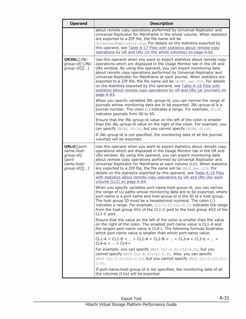
Operand Description
about remote copy operations performed by Universal Replicator andUniversal Replicator for Mainframe in the whole volume. When statisticsare exported to a ZIP file, the file name will beUniversalReplicator.zip. For details on the statistics exported bythis operand, see Table A-17 Files with statistics about remote copyoperations by UR and URz (In the whole volumes) on page A-62.
URJNL[[JNL-group-id]:[JNL-group-id]][…]
Use this operand when you want to export statistics about remote copyoperations which are displayed in the Usage Monitor tab in the UR andURz window. By using this operand, you can export monitoring dataabout remote copy operations performed by Universal Replicator andUniversal Replicator for Mainframe at each journal. When statistics areexported to a ZIP file, the file name will be URJNL_dat.ZIP. For detailson the statistics exported by this operand, see Table A-18 Files withstatistics about remote copy operations by UR and URz (at journals) onpage A-63.When you specify variables JNL-group-id, you can narrow the range ofjournals whose monitoring data are to be exported. JNL-group-id is ajournal number. The colon (:) indicates a range. For example, 00:05indicates journals from 00 to 05.Ensure that the JNL-group-id value on the left of the colon is smallerthan the JNL-group-id value on the right of the colon. For example, youcan specify URJNL 00:05, but you cannot specify URJNL 05:00.
If JNL-group-id is not specified, the monitoring data of all the journalvolumes will be exported.
URLU[[port-name.host-group-id]:[port-name.host-group-id]][…]
Use this operand when you want to export statistics about remote copyoperations which are displayed in the Usage Monitor tab in the UR andURz window. By using this operand, you can export monitoring dataabout remote copy operations performed by Universal Replicator andUniversal Replicator for Mainframe at each volume (LU). When statisticsare exported to a ZIP file, the file name will be URLU_dat.ZIP. Fordetails on the statistics exported by this operand, see Table A-19 Fileswith statistics about remote copy operations by UR and URz (for eachvolume (LU)) on page A-64.When you specify variables port-name.host-group-id, you can narrowthe range of LU paths whose monitoring data are to be exported, whereport-name is a port name and host-group-id is the ID of a host group.The host group ID must be a hexadecimal numeral. The colon (:)indicates a range. For example, CL1-C.01:CL1-C.03 indicates the rangefrom the host group #01 of the CL1-C port to the host group #03 of theCL1-C port.Ensure that the value on the left of the colon is smaller than the valueon the right of the colon. The smallest port-name value is CL1-A andthe largest port-name value is CL4-r. The following formula illustrateswhich port-name value is smaller than which port-name value:CL1-A < CL1-B < … < CL2-A < CL2-B < … < CL3-a < CL3-b < … <CL4-a < … < CL4-rFor example, you can specify URLU CL1-C.01:CL2-A.01, but youcannot specify URLU CL2-A.01:CL1-C.01. Also, you can specifyURLU CL1-C.01:CL1-C.03, but you cannot specify URLU CL1-C.03:CL1-C.01.
If port-name.host-group-id is not specified, the monitoring data of allthe volumes (LUs) will be exported.
Export Tool A-31Hitachi Virtual Storage Platform Performance Guide
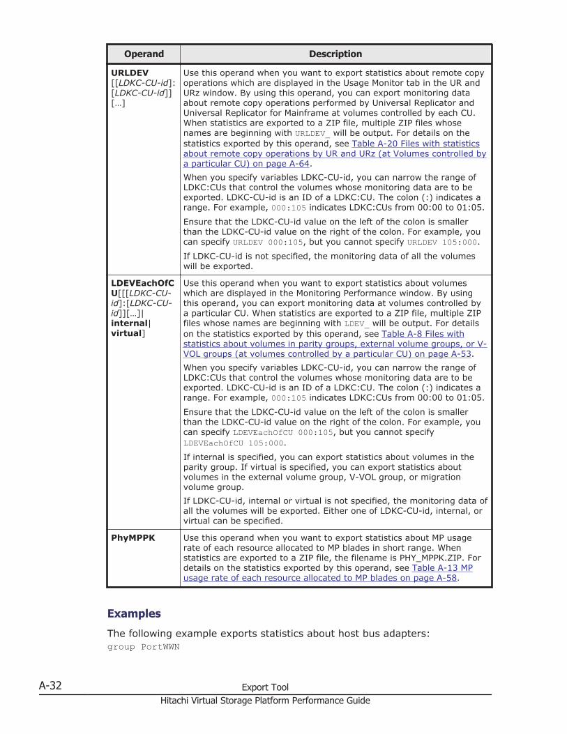
Operand Description
URLDEV[[LDKC-CU-id]:[LDKC-CU-id]][…]
Use this operand when you want to export statistics about remote copyoperations which are displayed in the Usage Monitor tab in the UR andURz window. By using this operand, you can export monitoring dataabout remote copy operations performed by Universal Replicator andUniversal Replicator for Mainframe at volumes controlled by each CU.When statistics are exported to a ZIP file, multiple ZIP files whosenames are beginning with URLDEV_ will be output. For details on thestatistics exported by this operand, see Table A-20 Files with statisticsabout remote copy operations by UR and URz (at Volumes controlled bya particular CU) on page A-64.When you specify variables LDKC-CU-id, you can narrow the range ofLDKC:CUs that control the volumes whose monitoring data are to beexported. LDKC-CU-id is an ID of a LDKC:CU. The colon (:) indicates arange. For example, 000:105 indicates LDKC:CUs from 00:00 to 01:05.
Ensure that the LDKC-CU-id value on the left of the colon is smallerthan the LDKC-CU-id value on the right of the colon. For example, youcan specify URLDEV 000:105, but you cannot specify URLDEV 105:000.
If LDKC-CU-id is not specified, the monitoring data of all the volumeswill be exported.
LDEVEachOfCU[[[LDKC-CU-id]:[LDKC-CU-id]][…]|internal|virtual]
Use this operand when you want to export statistics about volumeswhich are displayed in the Monitoring Performance window. By usingthis operand, you can export monitoring data at volumes controlled bya particular CU. When statistics are exported to a ZIP file, multiple ZIPfiles whose names are beginning with LDEV_ will be output. For detailson the statistics exported by this operand, see Table A-8 Files withstatistics about volumes in parity groups, external volume groups, or V-VOL groups (at volumes controlled by a particular CU) on page A-53.When you specify variables LDKC-CU-id, you can narrow the range ofLDKC:CUs that control the volumes whose monitoring data are to beexported. LDKC-CU-id is an ID of a LDKC:CU. The colon (:) indicates arange. For example, 000:105 indicates LDKC:CUs from 00:00 to 01:05.
Ensure that the LDKC-CU-id value on the left of the colon is smallerthan the LDKC-CU-id value on the right of the colon. For example, youcan specify LDEVEachOfCU 000:105, but you cannot specifyLDEVEachOfCU 105:000.
If internal is specified, you can export statistics about volumes in theparity group. If virtual is specified, you can export statistics aboutvolumes in the external volume group, V-VOL group, or migrationvolume group.If LDKC-CU-id, internal or virtual is not specified, the monitoring data ofall the volumes will be exported. Either one of LDKC-CU-id, internal, orvirtual can be specified.
PhyMPPK Use this operand when you want to export statistics about MP usagerate of each resource allocated to MP blades in short range. Whenstatistics are exported to a ZIP file, the filename is PHY_MPPK.ZIP. Fordetails on the statistics exported by this operand, see Table A-13 MPusage rate of each resource allocated to MP blades on page A-58.
Examples
The following example exports statistics about host bus adapters:group PortWWN
A-32 Export ToolHitachi Virtual Storage Platform Performance Guide
The following example exports statistics about three ports (CL1-A, CL1-B, andCL1-C):group Port CL1-A:CL1-CThe following example exports statistics about six ports (CL1-A to CL1-C, andCL2-A to CL2-C)group Port CL1-A:CL1-C CL2-A:CL2-CThe following example exports statistics about the parity group 1-3:group PG 1-3:1-3The following example exports statistics about the parity group 1-3 and otherparity groups whose ID is larger than 1-3 (for example, 1-4 and 1-5):group PG 1-3:The following example exports statistics about the external volume groupsE1-1 to E1-5:group PG E1-1:E1-5The following example exports statistics about the parity group 1-3 and otherparity groups whose ID is smaller than 1-3 (for example, 1-1 and 1-2):group LDEV:1-3The following example exports statistics about LU paths for the host group(host storage domain) ID 01 for the port CL1-A:group LU CL1-A.01:CL1-A.01
Short-range
Description
Use this subcommand to specify a term of monitoring data to be exportedinto files. Use this subcommand when you want to narrow the export-targetterm within the stored data.
The short-range subcommand is valid for monitoring data in short range.Short-range monitoring data appears in the following windows:
• The Monitor Performance window when Short-range is selected as thestoring period
• The Usage Monitor tab in the TC and TCz windows• The Usage Monitor tab in the UR and URz windows
All the monitoring items are stored in short range. Therefore, you can use theshort-range subcommand whichever operand you specify to the groupsubcommand. If you run the Export Tool without specifying the short-rangesubcommand, the data stored in the whole monitoring term will be exported.
The login subcommand must execute before the short-range subcommandexecutes.
Export Tool A-33Hitachi Virtual Storage Platform Performance Guide
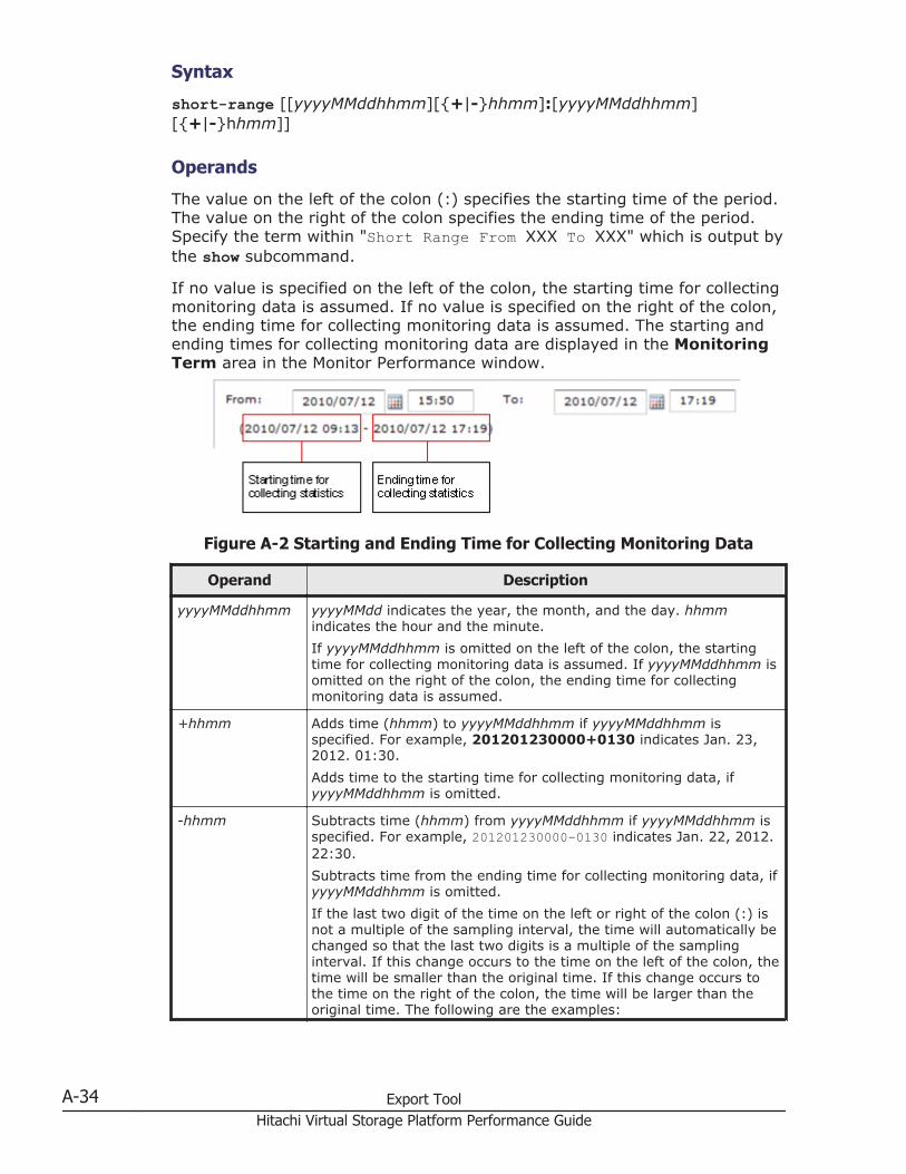
Syntax
short-range [[yyyyMMddhhmm][{+|-}hhmm]:[yyyyMMddhhmm][{+|-}hhmm]]
Operands
The value on the left of the colon (:) specifies the starting time of the period.The value on the right of the colon specifies the ending time of the period.Specify the term within "Short Range From XXX To XXX" which is output bythe show subcommand.
If no value is specified on the left of the colon, the starting time for collectingmonitoring data is assumed. If no value is specified on the right of the colon,the ending time for collecting monitoring data is assumed. The starting andending times for collecting monitoring data are displayed in the MonitoringTerm area in the Monitor Performance window.
Figure A-2 Starting and Ending Time for Collecting Monitoring Data
Operand Description
yyyyMMddhhmm yyyyMMdd indicates the year, the month, and the day. hhmmindicates the hour and the minute.If yyyyMMddhhmm is omitted on the left of the colon, the startingtime for collecting monitoring data is assumed. If yyyyMMddhhmm isomitted on the right of the colon, the ending time for collectingmonitoring data is assumed.
+hhmm Adds time (hhmm) to yyyyMMddhhmm if yyyyMMddhhmm isspecified. For example, 201201230000+0130 indicates Jan. 23,2012. 01:30.Adds time to the starting time for collecting monitoring data, ifyyyyMMddhhmm is omitted.
-hhmm Subtracts time (hhmm) from yyyyMMddhhmm if yyyyMMddhhmm isspecified. For example, 201201230000-0130 indicates Jan. 22, 2012.22:30.Subtracts time from the ending time for collecting monitoring data, ifyyyyMMddhhmm is omitted.If the last two digit of the time on the left or right of the colon (:) isnot a multiple of the sampling interval, the time will automatically bechanged so that the last two digits is a multiple of the samplinginterval. If this change occurs to the time on the left of the colon, thetime will be smaller than the original time. If this change occurs tothe time on the right of the colon, the time will be larger than theoriginal time. The following are the examples:
A-34 Export ToolHitachi Virtual Storage Platform Performance Guide
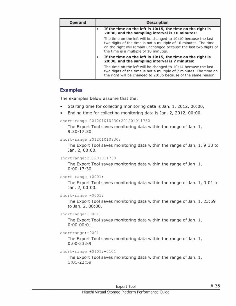
Operand Description
• If the time on the left is 10:15, the time on the right is20:30, and the sampling interval is 10 minutes:The time on the left will be changed to 10:10 because the lasttwo digits of the time is not a multiple of 10 minutes. The timeon the right will remain unchanged because the last two digits ofthe time is a multiple of 10 minutes.
• If the time on the left is 10:15, the time on the right is20:30, and the sampling interval is 7 minutes:The time on the left will be changed to 10:14 because the lasttwo digits of the time is not a multiple of 7 minutes. The time onthe right will be changed to 20:35 because of the same reason.
Examples
The examples below assume that the:
• Starting time for collecting monitoring data is Jan. 1, 2012, 00:00,• Ending time for collecting monitoring data is Jan. 2, 2012, 00:00.
short-range 201201010930:201201011730The Export Tool saves monitoring data within the range of Jan. 1,9:30-17:30.
short-range 201201010930:The Export Tool saves monitoring data within the range of Jan. 1, 9:30 toJan. 2, 00:00.
shortrange:201201011730The Export Tool saves monitoring data within the range of Jan. 1,0:00-17:30.
short-range +0001:The Export Tool saves monitoring data within the range of Jan. 1, 0:01 toJan. 2, 00:00.
short-range -0001:The Export Tool saves monitoring data within the range of Jan. 1, 23:59to Jan. 2, 00:00.
shortrange:+0001The Export Tool saves monitoring data within the range of Jan. 1,0:00-00:01.
shortrange:-0001The Export Tool saves monitoring data within the range of Jan. 1,0:00-23:59.
short-range +0101:-0101The Export Tool saves monitoring data within the range of Jan. 1,1:01-22:59.
Export Tool A-35Hitachi Virtual Storage Platform Performance Guide
short-range 201201010900+0130:201201011700-0130The Export Tool saves monitoring data within the range of Jan. 1,10:30-15:30.
short-range 201201010900-0130:201201011700+0130The Export Tool saves monitoring data within the range of Jan. 1,7:30-18:30.
short-range 201201010900-0130:The Export Tool saves monitoring data within the range of Jan. 1, 7:30 toJan. 2, 00:00.
long-range
Description
The long-range subcommand is used to specify a monitoring term (timerange) for collecting monitoring data to be exported into files. Use thissubcommand when you want to narrow the export-target term within thestored data.
The long-range subcommand is valid for monitoring data in long range. Themonitoring data in long range is the contents displayed in the Physical tab ofthe Performance Management window with selecting long-range as thestoring period.
The monitoring items whose data can be stored in long range are limited. Thefollowing table shows the monitoring items to which the long-rangesubcommand can be applied, and also shows the operands to export thosemonitoring items.
Monitoring Data Operands of the groupsubcommand
Usage statistics about parity groups PhyPG Long
Usage statistics about volumes PhyLDEV Long
Usage statistics about MPs and data recovery andreconstruction processors
PhyProc Long
Usage statistics about access paths and writepending rate
PhyESW Long
If you run the Export Tool without specifying the long-range subcommand,the data stored in the whole monitoring term will be exported.
The login subcommand must execute before the long-range subcommandexecutes.
Syntax
long-range [[yyyyMMddhhmm][{+|-}ddhhmm]:[yyyyMMddhhmm][{+|-}ddhhmm]]
A-36 Export ToolHitachi Virtual Storage Platform Performance Guide
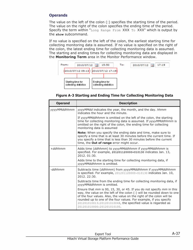
Operands
The value on the left of the colon (:) specifies the starting time of the period.The value on the right of the colon specifies the ending time of the period.Specify the term within "Long Range From XXX To XXX" which is output bythe show subcommand.
If no value is specified on the left of the colon, the earliest starting time forcollecting monitoring data is assumed. If no value is specified on the right ofthe colon, the latest ending time for collecting monitoring data is assumed.The starting and ending times for collecting monitoring data are displayed inthe Monitoring Term area in the Monitor Performance window.
Figure A-3 Starting and Ending Time for Collecting Monitoring Data
Operand Description
yyyyMMddhhmm yyyyMMdd indicates the year, the month, and the day. hhmmindicates the hour and the minute.If yyyyMMddhhmm is omitted on the left of the colon, the startingtime for collecting monitoring data is assumed. If yyyyMMddhhmm isomitted on the right of the colon, the ending time for collectingmonitoring data is assumedNote: When you specify the ending date and time, make sure tospecify a time that is at least 30 minutes before the current time. Ifyou specify a time that is less than 30 minutes before the currenttime, the Out of range error might occur.
+ddhhmm Adds time (ddhhmm) to yyyyMMddhhmm if yyyyMMddhhmm isspecified. For example, 201201120000+010130 indicates Jan. 13,2012. 01:30.Adds time to the starting time for collecting monitoring data, ifyyyyMMddhhmm is omitted.
-ddhhmm Subtracts time (ddhhmm) from yyyyMMddhhmm if yyyyMMddhhmmis specified. For example, 201201120000-010130 indicates Jan. 10,2012. 22:30.Subtracts time from the ending time for collecting monitoring data, ifyyyyMMddhhmm is omitted.Ensure that mm is 00, 15, 30, or 45. If you do not specify mm in thisway, the value on the left of the colon (:) will be rounded down to oneof the four values. Also, the value on the right of the colon will berounded up to one of the four values. For example, if you specify201201010013:201201010048, the specified value is regarded as201201010000:201201010100.
Export Tool A-37Hitachi Virtual Storage Platform Performance Guide
Examples
The examples below assume that:
• the starting time for collecting monitoring data is Jan. 1, 2012, 00:00,• the ending time for collecting monitoring data is Jan. 2, 2012, 00:00.
long-range 201201010930:201201011730The Export Tool saves monitoring data within the range of Jan. 1, 9:30 toJan. 1, 17:30.
long-range 201201010930:The Export Tool saves monitoring data within the range of Jan. 1, 9:30 toJan. 2, 00:00 (the ending time).
longrange:201201011730The Export Tool saves monitoring data within the range of Jan. 1, 0:00(the starting time) to Jan. 1, 17:30.
long-range +000015:The Export Tool saves monitoring data within the range of Jan. 1, 0:15(the starting time + 15 minutes) to Jan. 2, 00:00.
long-range -000015:The Export Tool saves monitoring data within the range of Jan. 1, 23:45to Jan. 2, 00:00.
longrange:+000015The Export Tool saves monitoring data within the range of Jan. 1, 0:00 toJan. 1, 00:15.
longrange:-000015The Export Tool saves monitoring data within the range of Jan. 1, 0:00 toJan. 1, 23:45.
long-range +000115:-000115The Export Tool saves monitoring data within the range of Jan. 1, 1:15 toJan. 1, 22:45.
long-range 201201010900+000130:201201011700-000130The Export Tool saves monitoring data within the range of Jan. 1, 10:30to Jan. 1, 15:30.
long-range 201201010900-000130:201201011700+000130The Export Tool saves monitoring data within the range of Jan. 1, 7:30 toJan. 1, 18:30.
long-range 201201010900-000130:The Export Tool saves monitoring data within the range of Jan. 1, 7:30 toJan. 2, 00:00.
A-38 Export ToolHitachi Virtual Storage Platform Performance Guide
outpath
Description
The outpath subcommand specifies the directory to which monitoring datawill be exported.
Syntax
outpath [path]
Operands
Operand Description
path Specifies the directory in which files will be saved.If the directory includes any non-alphanumeric character, the directorymust be enclosed by double quotation marks ("). If you want to specifya back slash (\) in the character string enclosed by double quotationmarks, repeat the back slash twice for example, \\.If the specified directory does not exist, this subcommand creates adirectory that has the specified name.If this operand is omitted, the current directory is assumed.
Examples
The following example saves files in the directory C:\Project\out on aWindows system:outpath "C:\\Project\\out"The following example saves files in the out directory in the currentdirectory:outpath out
option
Description
This subcommand specifies the following:
• whether to compress monitoring data in ZIP files• whether to overwrite or delete existing files and directories when saving
monitoring data in files
Syntax
option [compress|nocompress] [ask|clear|noclear]
Export Tool A-39Hitachi Virtual Storage Platform Performance Guide
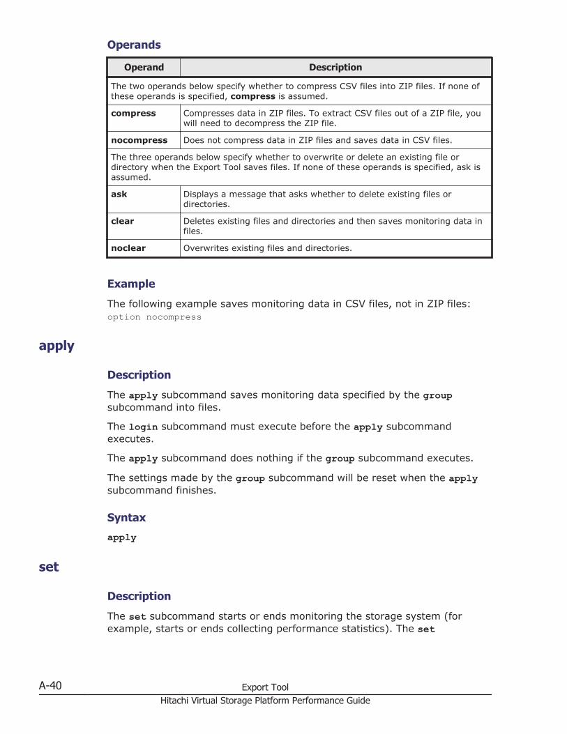
Operands
Operand Description
The two operands below specify whether to compress CSV files into ZIP files. If none ofthese operands is specified, compress is assumed.
compress Compresses data in ZIP files. To extract CSV files out of a ZIP file, youwill need to decompress the ZIP file.
nocompress Does not compress data in ZIP files and saves data in CSV files.
The three operands below specify whether to overwrite or delete an existing file ordirectory when the Export Tool saves files. If none of these operands is specified, ask isassumed.
ask Displays a message that asks whether to delete existing files ordirectories.
clear Deletes existing files and directories and then saves monitoring data infiles.
noclear Overwrites existing files and directories.
Example
The following example saves monitoring data in CSV files, not in ZIP files:option nocompress
apply
Description
The apply subcommand saves monitoring data specified by the groupsubcommand into files.
The login subcommand must execute before the apply subcommandexecutes.
The apply subcommand does nothing if the group subcommand executes.
The settings made by the group subcommand will be reset when the applysubcommand finishes.
Syntax
apply
set
Description
The set subcommand starts or ends monitoring the storage system (forexample, starts or ends collecting performance statistics). The set
A-40 Export ToolHitachi Virtual Storage Platform Performance Guide
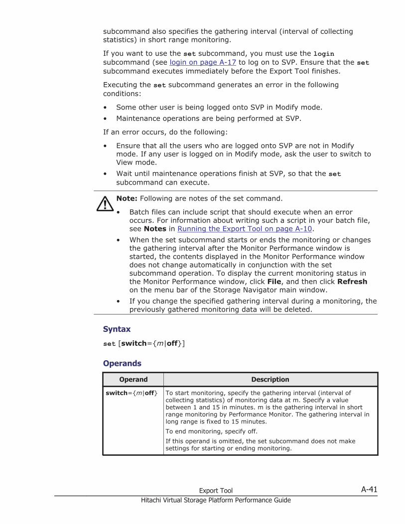
subcommand also specifies the gathering interval (interval of collectingstatistics) in short range monitoring.
If you want to use the set subcommand, you must use the loginsubcommand (see login on page A-17 to log on to SVP. Ensure that the setsubcommand executes immediately before the Export Tool finishes.
Executing the set subcommand generates an error in the followingconditions:
• Some other user is being logged onto SVP in Modify mode.• Maintenance operations are being performed at SVP.
If an error occurs, do the following:
• Ensure that all the users who are logged onto SVP are not in Modifymode. If any user is logged on in Modify mode, ask the user to switch toView mode.
• Wait until maintenance operations finish at SVP, so that the setsubcommand can execute.
Note: Following are notes of the set command.
• Batch files can include script that should execute when an erroroccurs. For information about writing such a script in your batch file,see Notes in Running the Export Tool on page A-10.
• When the set subcommand starts or ends the monitoring or changesthe gathering interval after the Monitor Performance window isstarted, the contents displayed in the Monitor Performance windowdoes not change automatically in conjunction with the setsubcommand operation. To display the current monitoring status inthe Monitor Performance window, click File, and then click Refreshon the menu bar of the Storage Navigator main window.
• If you change the specified gathering interval during a monitoring, thepreviously gathered monitoring data will be deleted.
Syntax
set [switch={m|off}]
Operands
Operand Description
switch={m|off} To start monitoring, specify the gathering interval (interval ofcollecting statistics) of monitoring data at m. Specify a valuebetween 1 and 15 in minutes. m is the gathering interval in shortrange monitoring by Performance Monitor. The gathering interval inlong range is fixed to 15 minutes.To end monitoring, specify off.If this operand is omitted, the set subcommand does not makesettings for starting or ending monitoring.
Export Tool A-41Hitachi Virtual Storage Platform Performance Guide
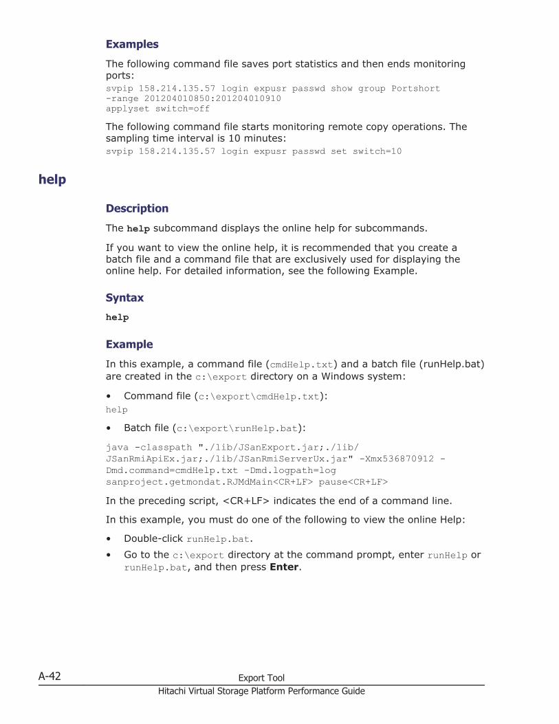
Examples
The following command file saves port statistics and then ends monitoringports:svpip 158.214.135.57 login expusr passwd show group Portshort-range 201204010850:201204010910applyset switch=offThe following command file starts monitoring remote copy operations. Thesampling time interval is 10 minutes:svpip 158.214.135.57 login expusr passwd set switch=10
help
Description
The help subcommand displays the online help for subcommands.
If you want to view the online help, it is recommended that you create abatch file and a command file that are exclusively used for displaying theonline help. For detailed information, see the following Example.
Syntax
help
Example
In this example, a command file (cmdHelp.txt) and a batch file (runHelp.bat)are created in the c:\export directory on a Windows system:
• Command file (c:\export\cmdHelp.txt):help• Batch file (c:\export\runHelp.bat):
java -classpath "./lib/JSanExport.jar;./lib/JSanRmiApiEx.jar;./lib/JSanRmiServerUx.jar" -Xmx536870912 -Dmd.command=cmdHelp.txt -Dmd.logpath=logsanproject.getmondat.RJMdMain<CR+LF> pause<CR+LF>In the preceding script, <CR+LF> indicates the end of a command line.
In this example, you must do one of the following to view the online Help:
• Double-click runHelp.bat.• Go to the c:\export directory at the command prompt, enter runHelp or
runHelp.bat, and then press Enter.
A-42 Export ToolHitachi Virtual Storage Platform Performance Guide
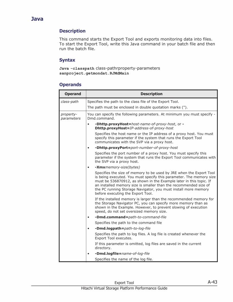
Java
Description
This command starts the Export Tool and exports monitoring data into files.To start the Export Tool, write this Java command in your batch file and thenrun the batch file.
Syntax
Java -classpath class-pathrproperty-parameterssanproject.getmondat.RJMdMain
Operands
Operand Description
class-path Specifies the path to the class file of the Export Tool.The path must be enclosed in double quotation marks (").
property-parameters
You can specify the following parameters. At minimum you must specify -Dmd.command.• -Dhttp.proxyHost=host-name-of-proxy-host, or -
Dhttp.proxyHost=IP-address-of-proxy-hostSpecifies the host name or the IP address of a proxy host. You mustspecify this parameter if the system that runs the Export Toolcommunicates with the SVP via a proxy host.
• -Dhttp.proxyPort=port-number-of-proxy-hostSpecifies the port number of a proxy host. You must specify thisparameter if the system that runs the Export Tool communicates withthe SVP via a proxy host.
• -Xmxmemory-size(bytes)Specifies the size of memory to be used by JRE when the Export Toolis being executed. You must specify this parameter. The memory sizemust be 536870912, as shown in the Example later in this topic. Ifan installed memory size is smaller than the recommended size ofthe PC running Storage Navigator, you must install more memorybefore executing the Export Tool.If the installed memory is larger than the recommended memory forthe Storage Navigator PC, you can specify more memory than asshown in the Example. However, to prevent slowing of executionspeed, do not set oversized memory size.
• -Dmd.command=path-to-command-fileSpecifies the path to the command file
• -Dmd.logpath=path-to-log-fileSpecifies the path to log files. A log file is created whenever theExport Tool executes.If this parameter is omitted, log files are saved in the currentdirectory.
• -Dmd.logfile=name-of-log-fileSpecifies the name of the log file.
Export Tool A-43Hitachi Virtual Storage Platform Performance Guide
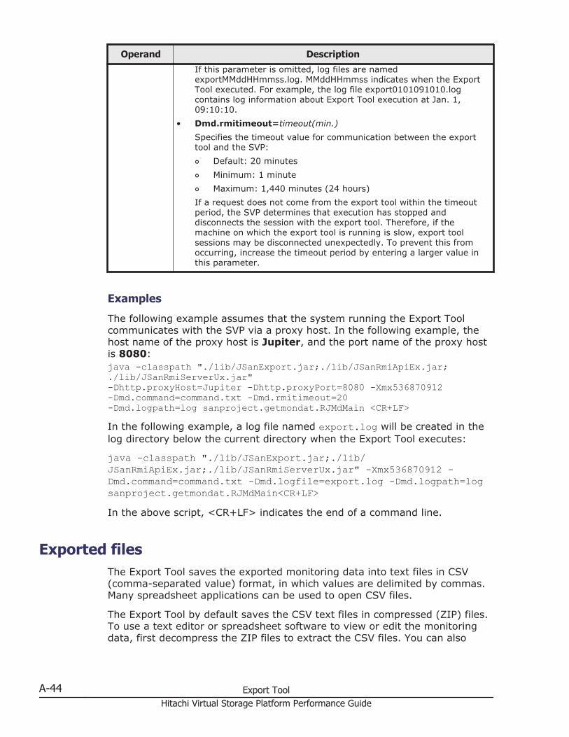
Operand Description
If this parameter is omitted, log files are namedexportMMddHHmmss.log. MMddHHmmss indicates when the ExportTool executed. For example, the log file export0101091010.logcontains log information about Export Tool execution at Jan. 1,09:10:10.
• Dmd.rmitimeout=timeout(min.)Specifies the timeout value for communication between the exporttool and the SVP:¢ Default: 20 minutes¢ Minimum: 1 minute¢ Maximum: 1,440 minutes (24 hours)If a request does not come from the export tool within the timeoutperiod, the SVP determines that execution has stopped anddisconnects the session with the export tool. Therefore, if themachine on which the export tool is running is slow, export toolsessions may be disconnected unexpectedly. To prevent this fromoccurring, increase the timeout period by entering a larger value inthis parameter.
Examples
The following example assumes that the system running the Export Toolcommunicates with the SVP via a proxy host. In the following example, thehost name of the proxy host is Jupiter, and the port name of the proxy hostis 8080:java -classpath "./lib/JSanExport.jar;./lib/JSanRmiApiEx.jar;./lib/JSanRmiServerUx.jar"-Dhttp.proxyHost=Jupiter -Dhttp.proxyPort=8080 -Xmx536870912 -Dmd.command=command.txt -Dmd.rmitimeout=20-Dmd.logpath=log sanproject.getmondat.RJMdMain <CR+LF>In the following example, a log file named export.log will be created in thelog directory below the current directory when the Export Tool executes:
java -classpath "./lib/JSanExport.jar;./lib/JSanRmiApiEx.jar;./lib/JSanRmiServerUx.jar" -Xmx536870912 -Dmd.command=command.txt -Dmd.logfile=export.log -Dmd.logpath=logsanproject.getmondat.RJMdMain<CR+LF>In the above script, <CR+LF> indicates the end of a command line.
Exported filesThe Export Tool saves the exported monitoring data into text files in CSV(comma-separated value) format, in which values are delimited by commas.Many spreadsheet applications can be used to open CSV files.
The Export Tool by default saves the CSV text files in compressed (ZIP) files.To use a text editor or spreadsheet software to view or edit the monitoringdata, first decompress the ZIP files to extract the CSV files. You can also
A-44 Export ToolHitachi Virtual Storage Platform Performance Guide
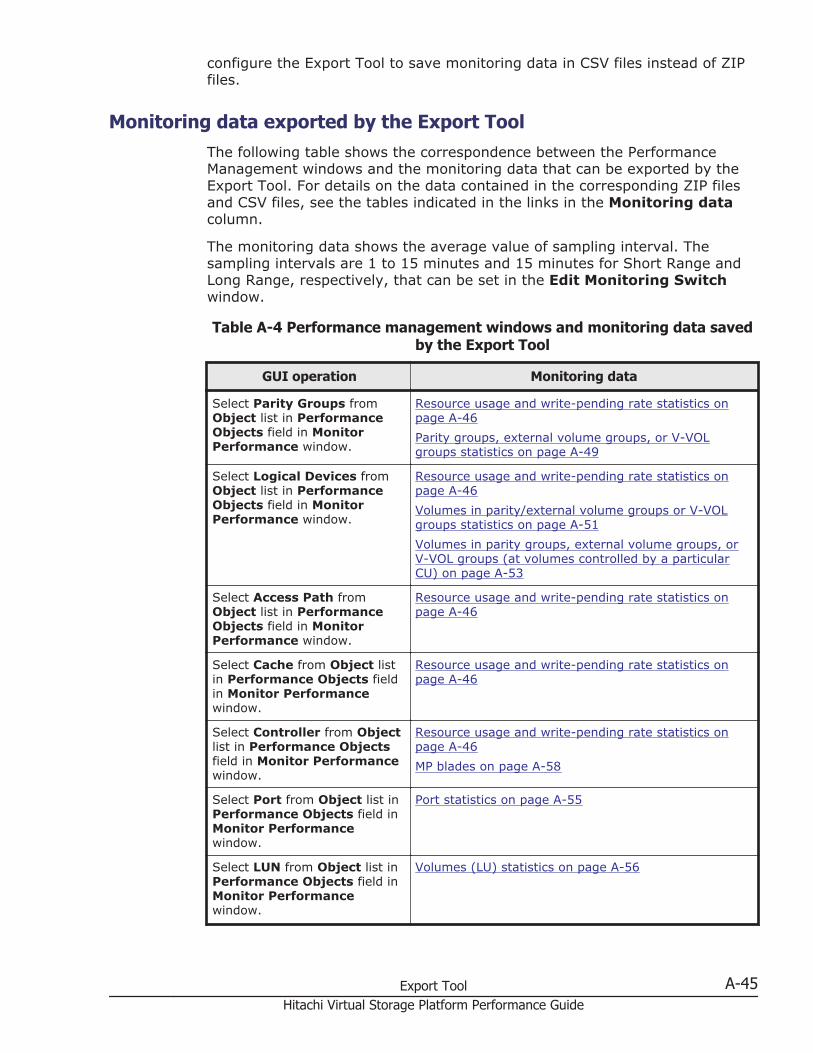
configure the Export Tool to save monitoring data in CSV files instead of ZIPfiles.
Monitoring data exported by the Export ToolThe following table shows the correspondence between the PerformanceManagement windows and the monitoring data that can be exported by theExport Tool. For details on the data contained in the corresponding ZIP filesand CSV files, see the tables indicated in the links in the Monitoring datacolumn.
The monitoring data shows the average value of sampling interval. Thesampling intervals are 1 to 15 minutes and 15 minutes for Short Range andLong Range, respectively, that can be set in the Edit Monitoring Switchwindow.
Table A-4 Performance management windows and monitoring data savedby the Export Tool
GUI operation Monitoring data
Select Parity Groups fromObject list in PerformanceObjects field in MonitorPerformance window.
Resource usage and write-pending rate statistics onpage A-46Parity groups, external volume groups, or V-VOLgroups statistics on page A-49
Select Logical Devices fromObject list in PerformanceObjects field in MonitorPerformance window.
Resource usage and write-pending rate statistics onpage A-46Volumes in parity/external volume groups or V-VOLgroups statistics on page A-51Volumes in parity groups, external volume groups, orV-VOL groups (at volumes controlled by a particularCU) on page A-53
Select Access Path fromObject list in PerformanceObjects field in MonitorPerformance window.
Resource usage and write-pending rate statistics onpage A-46
Select Cache from Object listin Performance Objects fieldin Monitor Performancewindow.
Resource usage and write-pending rate statistics onpage A-46
Select Controller from Objectlist in Performance Objectsfield in Monitor Performancewindow.
Resource usage and write-pending rate statistics onpage A-46MP blades on page A-58
Select Port from Object list inPerformance Objects field inMonitor Performancewindow.
Port statistics on page A-55
Select LUN from Object list inPerformance Objects field inMonitor Performancewindow.
Volumes (LU) statistics on page A-56
Export Tool A-45Hitachi Virtual Storage Platform Performance Guide
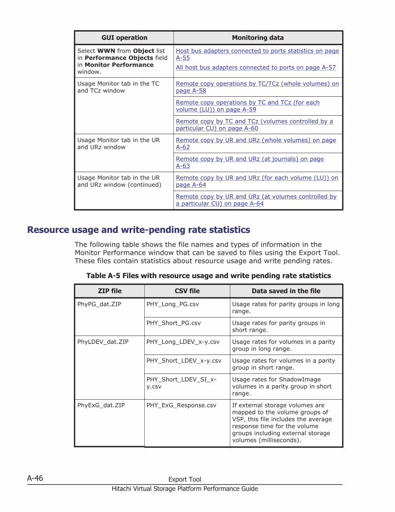
GUI operation Monitoring data
Select WWN from Object listin Performance Objects fieldin Monitor Performancewindow.
Host bus adapters connected to ports statistics on pageA-55All host bus adapters connected to ports on page A-57
Usage Monitor tab in the TCand TCz window
Remote copy operations by TC/TCz (whole volumes) onpage A-58
Remote copy operations by TC and TCz (for eachvolume (LU)) on page A-59
Remote copy by TC and TCz (volumes controlled by aparticular CU) on page A-60
Usage Monitor tab in the URand URz window
Remote copy by UR and URz (whole volumes) on pageA-62
Remote copy by UR and URz (at journals) on pageA-63
Usage Monitor tab in the URand URz window (continued)
Remote copy by UR and URz (for each volume (LU)) onpage A-64
Remote copy by UR and URz (at volumes controlled bya particular CU) on page A-64
Resource usage and write-pending rate statisticsThe following table shows the file names and types of information in theMonitor Performance window that can be saved to files using the Export Tool.These files contain statistics about resource usage and write pending rates.
Table A-5 Files with resource usage and write pending rate statistics
ZIP file CSV file Data saved in the file
PhyPG_dat.ZIP PHY_Long_PG.csv Usage rates for parity groups in longrange.
PHY_Short_PG.csv Usage rates for parity groups inshort range.
PhyLDEV_dat.ZIP PHY_Long_LDEV_x-y.csv Usage rates for volumes in a paritygroup in long range.
PHY_Short_LDEV_x-y.csv Usage rates for volumes in a paritygroup in short range.
PHY_Short_LDEV_SI_x-y.csv
Usage rates for ShadowImagevolumes in a parity group in shortrange.
PhyExG_dat.ZIP PHY_ExG_Response.csv If external storage volumes aremapped to the volume groups ofVSP, this file includes the averageresponse time for the volumegroups including external storagevolumes (milliseconds).
A-46 Export ToolHitachi Virtual Storage Platform Performance Guide
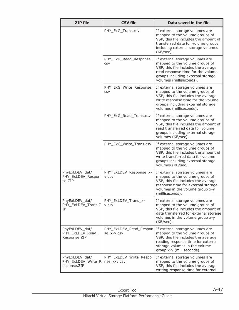
ZIP file CSV file Data saved in the file
PHY_ExG_Trans.csv If external storage volumes aremapped to the volume groups ofVSP, this file includes the amount oftransferred data for volume groupsincluding external storage volumes(KB/sec).
PHY_ExG_Read_Response.csv
If external storage volumes aremapped to the volume groups ofVSP, this file includes the averageread response time for the volumegroups including external storagevolumes (milliseconds).
PHY_ExG_Write_Response.csv
If external storage volumes aremapped to the volume groups ofVSP, this file includes the averagewrite response time for the volumegroups including external storagevolumes (milliseconds).
PHY_ExG_Read_Trans.csv If external storage volumes aremapped to the volume groups ofVSP, this file includes the amount ofread transferred data for volumegroups including external storagevolumes (KB/sec).
PHY_ExG_Write_Trans.csv If external storage volumes aremapped to the volume groups ofVSP, this file includes the amount ofwrite transferred data for volumegroups including external storagevolumes (KB/sec).
PhyExLDEV_dat/PHY_ExLDEV_Response.ZIP
PHY_ExLDEV_Response_x-y.csv
If external storage volumes aremapped to the volume groups ofVSP, this file includes the averageresponse time for external storagevolumes in the volume group x-y(milliseconds).
PhyExLDEV_dat/PHY_ExLDEV_Trans.ZIP
PHY_ExLDEV_Trans_x-y.csv
If external storage volumes aremapped to the volume groups ofVSP, this file includes the amount ofdata transferred for external storagevolumes in the volume group x-y(KB/sec).
PhyExLDEV_dat/PHY_ExLDEV_Read_Response.ZIP
PHY_ExLDEV_Read_Response_x-y.csv
If external storage volumes aremapped to the volume groups ofVSP, this file includes the averagereading response time for externalstorage volumes in the volumegroup x-y (milliseconds).
PhyExLDEV_dat/PHY_ExLDEV_Write_Response.ZIP
PHY_ExLDEV_Write_Response_x-y.csv
If external storage volumes aremapped to the volume groups ofVSP, this file includes the averagewriting response time for external
Export Tool A-47Hitachi Virtual Storage Platform Performance Guide
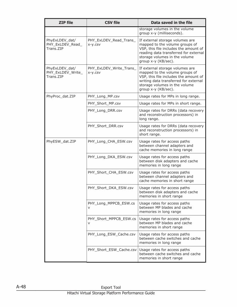
ZIP file CSV file Data saved in the file
storage volumes in the volumegroup x-y (milliseconds).
PhyExLDEV_dat/PHY_ExLDEV_Read_Trans.ZIP
PHY_ExLDEV_Read_Trans_x-y.csv
If external storage volumes aremapped to the volume groups ofVSP, this file includes the amount ofreading data transferred for externalstorage volumes in the volumegroup x-y (KB/sec).
PhyExLDEV_dat/PHY_ExLDEV_Write_Trans.ZIP
PHY_ExLDEV_Write_Trans_x-y.csv
If external storage volumes aremapped to the volume groups ofVSP, this file includes the amount ofwriting data transferred for externalstorage volumes in the volumegroup x-y (KB/sec).
PhyProc_dat.ZIP PHY_Long_MP.csv Usage rates for MPs in long range.
PHY_Short_MP.csv Usage rates for MPs in short range.
PHY_Long_DRR.csv Usage rates for DRRs (data recoveryand reconstruction processors) inlong range.
PHY_Short_DRR.csv Usage rates for DRRs (data recoveryand reconstruction processors) inshort range.
PhyESW_dat.ZIP PHY_Long_CHA_ESW.csv Usage rates for access pathsbetween channel adapters andcache memories in long range
PHY_Long_DKA_ESW.csv Usage rates for access pathsbetween disk adapters and cachememories in long range
PHY_Short_CHA_ESW.csv Usage rates for access pathsbetween channel adapters andcache memories in short range
PHY_Short_DKA_ESW.csv Usage rates for access pathsbetween disk adapters and cachememories in short range
PHY_Long_MPPCB_ESW.csv
Usage rates for access pathsbetween MP blades and cachememories in long range
PHY_Short_MPPCB_ESW.csv
Usage rates for access pathsbetween MP blades and cachememories in short range
PHY_Long_ESW_Cache.csv Usage rates for access pathsbetween cache switches and cachememories in long range
PHY_Short_ESW_Cache.csv Usage rates for access pathsbetween cache switches and cachememories in short range
A-48 Export ToolHitachi Virtual Storage Platform Performance Guide
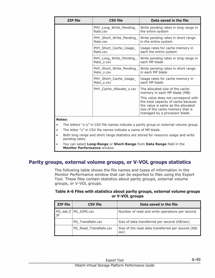
ZIP file CSV file Data saved in the file
PHY_Long_Write_Pending_Rate.csv
Write pending rates in long range inthe entire system
PHY_Short_Write_Pending_Rate.csv
Write pending rates in short rangein the entire system
PHY_Short_Cache_Usage_Rate.csv
Usage rates for cache memory ineach the entire system
PHY_Long_Write_Pending_Rate_z.csv
Write pending rates in long range ineach MP blade
PHY_Short_Write_Pending_Rate_z.csv
Write pending rates in short rangein each MP blade
PHY_Short_Cache_Usage_Rate_z.csv
Usage rates for cache memory ineach MP blade
PHY_Cache_Allocate_z.csv The allocated size of the cachememory in each MP blade (MB)This value does not correspond withthe total capacity of cache becausethe value is same as the allocatedsize of the cache memory that ismanaged by a processor blade.
Notes:• The letters “x-y” in CSV file names indicate a parity group or external volume group.• The letter “z” in CSV file names indicate a name of MP blade.• Both long range and short range statistics are stored for resource usage and write
pending rates.• You can select Long-Range or Short-Range from Data Range field in the
Monitor Performance window
Parity groups, external volume groups, or V-VOL groups statisticsThe following table shows the file names and types of information in theMonitor Performance window that can be exported to files using the ExportTool. These files contain statistics about parity groups, external volumegroups, or V-VOL groups.
Table A-6 Files with statistics about parity groups, external volume groupsor V-VOL groups
ZIP file CSV file Data saved in the file
PG_dat.ZIP
PG_IOPS.csv Number of read and write operations per second
PG_TransRate.csv Size of data transferred per second (KB/sec)
PG_Read_TransRate.csv Size of the read data transferred per second (KB/sec)
Export Tool A-49Hitachi Virtual Storage Platform Performance Guide
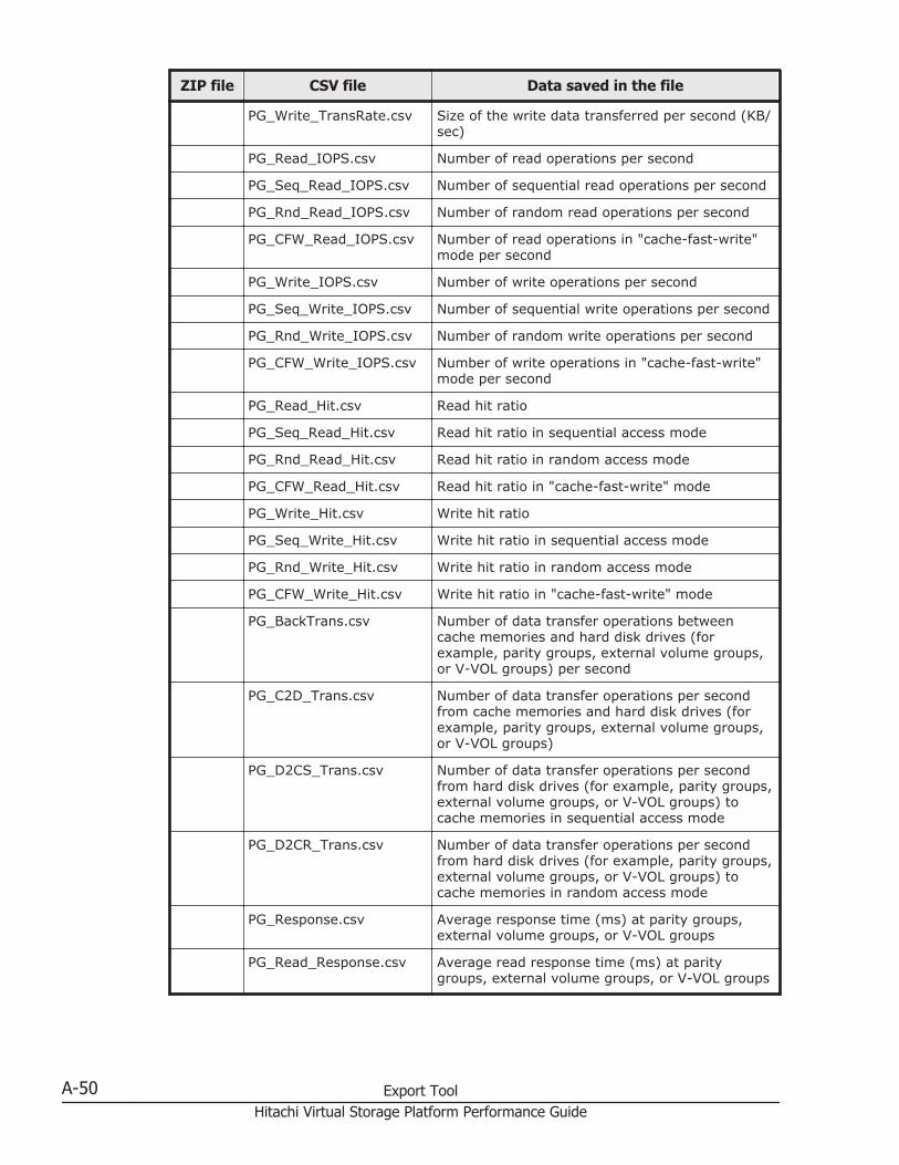
ZIP file CSV file Data saved in the file
PG_Write_TransRate.csv Size of the write data transferred per second (KB/sec)
PG_Read_IOPS.csv Number of read operations per second
PG_Seq_Read_IOPS.csv Number of sequential read operations per second
PG_Rnd_Read_IOPS.csv Number of random read operations per second
PG_CFW_Read_IOPS.csv Number of read operations in "cache-fast-write"mode per second
PG_Write_IOPS.csv Number of write operations per second
PG_Seq_Write_IOPS.csv Number of sequential write operations per second
PG_Rnd_Write_IOPS.csv Number of random write operations per second
PG_CFW_Write_IOPS.csv Number of write operations in "cache-fast-write"mode per second
PG_Read_Hit.csv Read hit ratio
PG_Seq_Read_Hit.csv Read hit ratio in sequential access mode
PG_Rnd_Read_Hit.csv Read hit ratio in random access mode
PG_CFW_Read_Hit.csv Read hit ratio in "cache-fast-write" mode
PG_Write_Hit.csv Write hit ratio
PG_Seq_Write_Hit.csv Write hit ratio in sequential access mode
PG_Rnd_Write_Hit.csv Write hit ratio in random access mode
PG_CFW_Write_Hit.csv Write hit ratio in "cache-fast-write" mode
PG_BackTrans.csv Number of data transfer operations betweencache memories and hard disk drives (forexample, parity groups, external volume groups,or V-VOL groups) per second
PG_C2D_Trans.csv Number of data transfer operations per secondfrom cache memories and hard disk drives (forexample, parity groups, external volume groups,or V-VOL groups)
PG_D2CS_Trans.csv Number of data transfer operations per secondfrom hard disk drives (for example, parity groups,external volume groups, or V-VOL groups) tocache memories in sequential access mode
PG_D2CR_Trans.csv Number of data transfer operations per secondfrom hard disk drives (for example, parity groups,external volume groups, or V-VOL groups) tocache memories in random access mode
PG_Response.csv Average response time (ms) at parity groups,external volume groups, or V-VOL groups
PG_Read_Response.csv Average read response time (ms) at paritygroups, external volume groups, or V-VOL groups
A-50 Export ToolHitachi Virtual Storage Platform Performance Guide
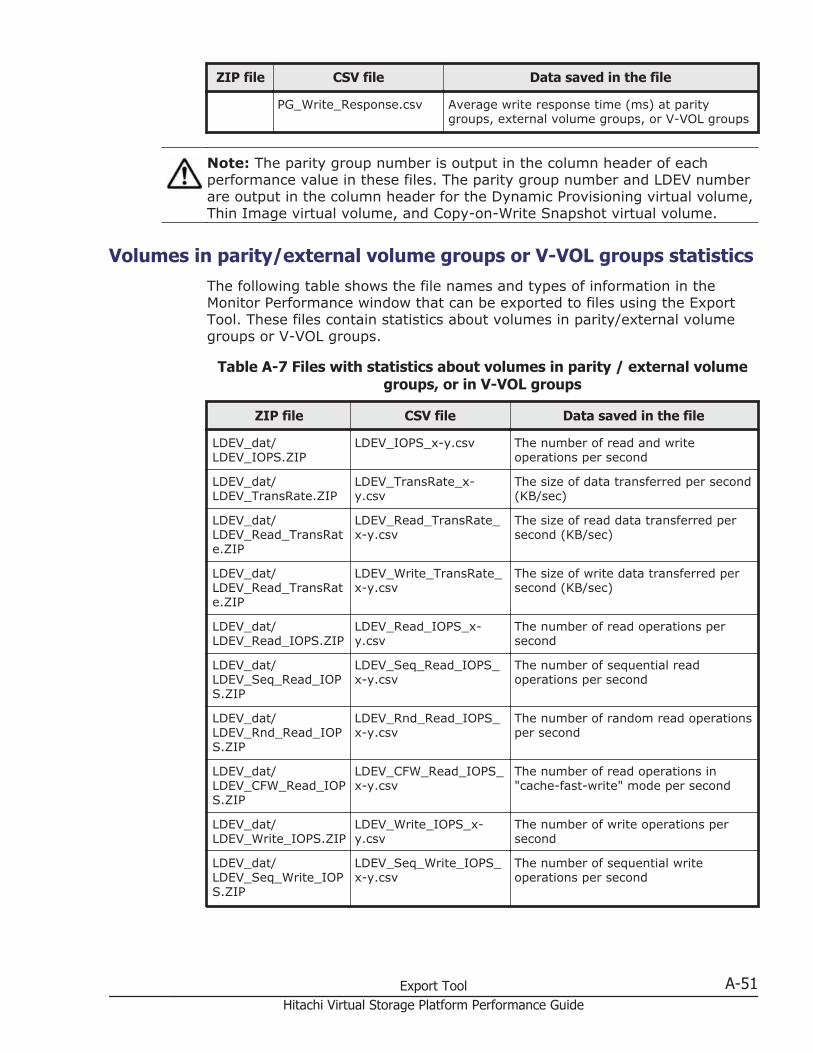
ZIP file CSV file Data saved in the file
PG_Write_Response.csv Average write response time (ms) at paritygroups, external volume groups, or V-VOL groups
Note: The parity group number is output in the column header of eachperformance value in these files. The parity group number and LDEV numberare output in the column header for the Dynamic Provisioning virtual volume,Thin Image virtual volume, and Copy-on-Write Snapshot virtual volume.
Volumes in parity/external volume groups or V-VOL groups statisticsThe following table shows the file names and types of information in theMonitor Performance window that can be exported to files using the ExportTool. These files contain statistics about volumes in parity/external volumegroups or V-VOL groups.
Table A-7 Files with statistics about volumes in parity / external volumegroups, or in V-VOL groups
ZIP file CSV file Data saved in the file
LDEV_dat/LDEV_IOPS.ZIP
LDEV_IOPS_x-y.csv The number of read and writeoperations per second
LDEV_dat/LDEV_TransRate.ZIP
LDEV_TransRate_x-y.csv
The size of data transferred per second(KB/sec)
LDEV_dat/LDEV_Read_TransRate.ZIP
LDEV_Read_TransRate_x-y.csv
The size of read data transferred persecond (KB/sec)
LDEV_dat/LDEV_Read_TransRate.ZIP
LDEV_Write_TransRate_x-y.csv
The size of write data transferred persecond (KB/sec)
LDEV_dat/LDEV_Read_IOPS.ZIP
LDEV_Read_IOPS_x-y.csv
The number of read operations persecond
LDEV_dat/LDEV_Seq_Read_IOPS.ZIP
LDEV_Seq_Read_IOPS_x-y.csv
The number of sequential readoperations per second
LDEV_dat/LDEV_Rnd_Read_IOPS.ZIP
LDEV_Rnd_Read_IOPS_x-y.csv
The number of random read operationsper second
LDEV_dat/LDEV_CFW_Read_IOPS.ZIP
LDEV_CFW_Read_IOPS_x-y.csv
The number of read operations in"cache-fast-write" mode per second
LDEV_dat/LDEV_Write_IOPS.ZIP
LDEV_Write_IOPS_x-y.csv
The number of write operations persecond
LDEV_dat/LDEV_Seq_Write_IOPS.ZIP
LDEV_Seq_Write_IOPS_x-y.csv
The number of sequential writeoperations per second
Export Tool A-51Hitachi Virtual Storage Platform Performance Guide
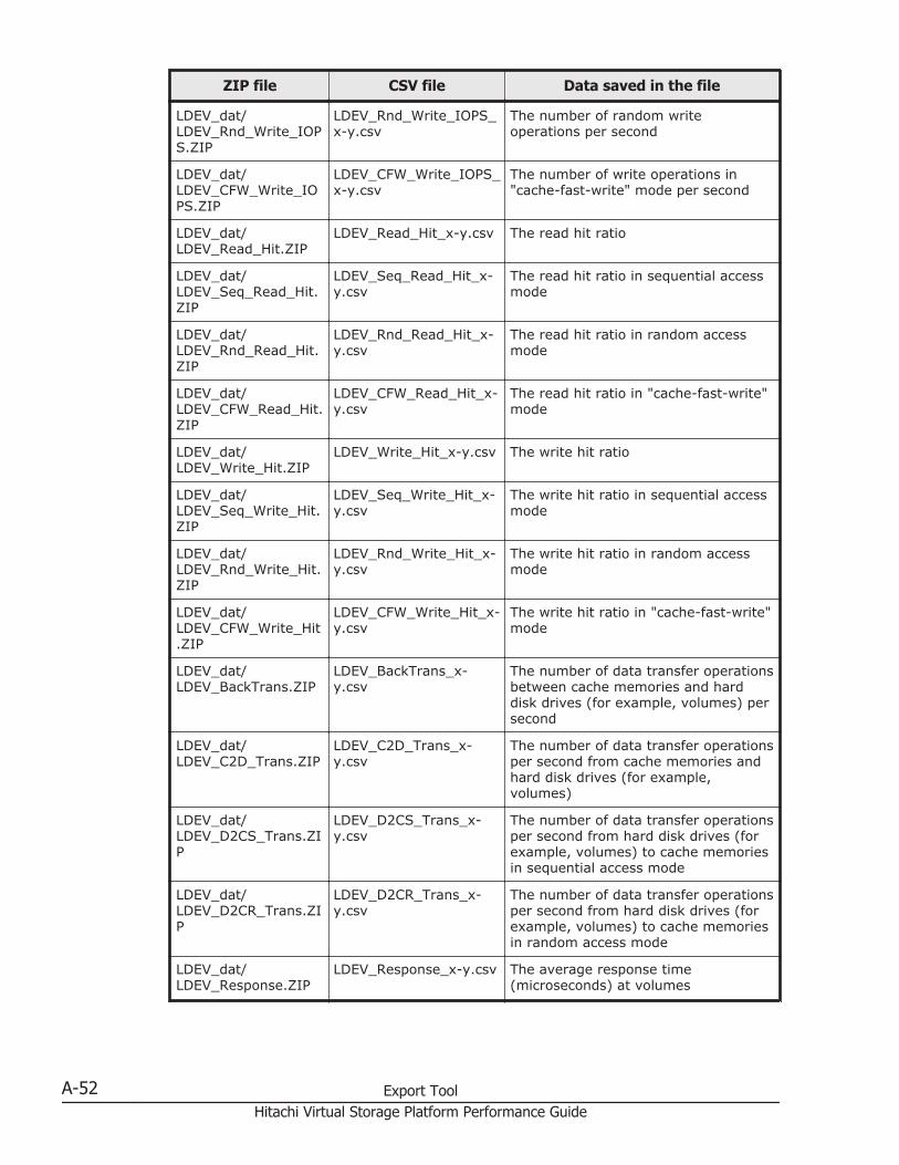
ZIP file CSV file Data saved in the file
LDEV_dat/LDEV_Rnd_Write_IOPS.ZIP
LDEV_Rnd_Write_IOPS_x-y.csv
The number of random writeoperations per second
LDEV_dat/LDEV_CFW_Write_IOPS.ZIP
LDEV_CFW_Write_IOPS_x-y.csv
The number of write operations in"cache-fast-write" mode per second
LDEV_dat/LDEV_Read_Hit.ZIP
LDEV_Read_Hit_x-y.csv The read hit ratio
LDEV_dat/LDEV_Seq_Read_Hit.ZIP
LDEV_Seq_Read_Hit_x-y.csv
The read hit ratio in sequential accessmode
LDEV_dat/LDEV_Rnd_Read_Hit.ZIP
LDEV_Rnd_Read_Hit_x-y.csv
The read hit ratio in random accessmode
LDEV_dat/LDEV_CFW_Read_Hit.ZIP
LDEV_CFW_Read_Hit_x-y.csv
The read hit ratio in "cache-fast-write"mode
LDEV_dat/LDEV_Write_Hit.ZIP
LDEV_Write_Hit_x-y.csv The write hit ratio
LDEV_dat/LDEV_Seq_Write_Hit.ZIP
LDEV_Seq_Write_Hit_x-y.csv
The write hit ratio in sequential accessmode
LDEV_dat/LDEV_Rnd_Write_Hit.ZIP
LDEV_Rnd_Write_Hit_x-y.csv
The write hit ratio in random accessmode
LDEV_dat/LDEV_CFW_Write_Hit.ZIP
LDEV_CFW_Write_Hit_x-y.csv
The write hit ratio in "cache-fast-write"mode
LDEV_dat/LDEV_BackTrans.ZIP
LDEV_BackTrans_x-y.csv
The number of data transfer operationsbetween cache memories and harddisk drives (for example, volumes) persecond
LDEV_dat/LDEV_C2D_Trans.ZIP
LDEV_C2D_Trans_x-y.csv
The number of data transfer operationsper second from cache memories andhard disk drives (for example,volumes)
LDEV_dat/LDEV_D2CS_Trans.ZIP
LDEV_D2CS_Trans_x-y.csv
The number of data transfer operationsper second from hard disk drives (forexample, volumes) to cache memoriesin sequential access mode
LDEV_dat/LDEV_D2CR_Trans.ZIP
LDEV_D2CR_Trans_x-y.csv
The number of data transfer operationsper second from hard disk drives (forexample, volumes) to cache memoriesin random access mode
LDEV_dat/LDEV_Response.ZIP
LDEV_Response_x-y.csv The average response time(microseconds) at volumes
A-52 Export ToolHitachi Virtual Storage Platform Performance Guide
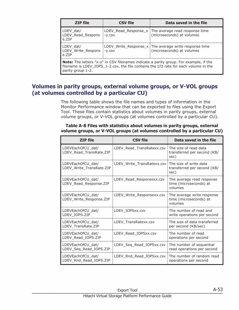
ZIP file CSV file Data saved in the file
LDEV_dat/LDEV_Read_Response.ZIP
LDEV_Read_Response_x-y.csv
The average read response time(microseconds) at volumes
LDEV_dat/LDEV_Write_Response.ZIP
LDEV_Write_Response_x-y.csv
The average write response time(microseconds) at volumes
Note: The letters "x-y" in CSV filenames indicate a parity group. For example, if thefilename is LDEV_IOPS_1-2.csv, the file contains the I/O rate for each volume in theparity group 1-2.
Volumes in parity groups, external volume groups, or V-VOL groups(at volumes controlled by a particular CU)
The following table shows the file names and types of information in theMonitor Performance window that can be exported to files using the ExportTool. These files contain statistics about volumes in parity groups, externalvolume groups, or V-VOL groups (at volumes controlled by a particular CU).
Table A-8 Files with statistics about volumes in parity groups, externalvolume groups, or V-VOL groups (at volumes controlled by a particular CU)
ZIP file CSV file Data saved in the file
LDEVEachOfCU_dat/LDEV_Read_TransRate.ZIP
LDEV_Read_TransRatexx.csv The size of read datatransferred per second (KB/sec)
LDEVEachOfCU_dat/LDEV_Write_TransRate.ZIP
LDEV_Write_TransRatexx.csv The size of write datatransferred per second (KB/sec)
LDEVEachOfCU_dat/LDEV_Read_Response.ZIP
LDEV_Read_Responsexx.csv The average read responsetime (microseconds) atvolumes
LDEVEachOfCU_dat/LDEV_Write_Response.ZIP
LDEV_Write_Responsexx.csv The average write responsetime (microseconds) atvolumes
LDEVEachOfCU_dat/LDEV_IOPS.ZIP
LDEV_IOPSxx.csv The number of read andwrite operations per second
LDEVEachOfCU_dat/LDEV_TransRate.ZIP
LDEV_TransRatexx.csv The size of data transferredper second (KB/sec)
LDEVEachOfCU_dat/LDEV_Read_IOPS.ZIP
LDEV_Read_IOPSxx.csv The number of readoperations per second
LDEVEachOfCU_dat/LDEV_Seq_Read_IOPS.ZIP
LDEV_Seq_Read_IOPSxx.csv The number of sequentialread operations per second
LDEVEachOfCU_dat/LDEV_Rnd_Read_IOPS.ZIP
LDEV_Rnd_Read_IOPSxx.csv The number of random readoperations per second
Export Tool A-53Hitachi Virtual Storage Platform Performance Guide
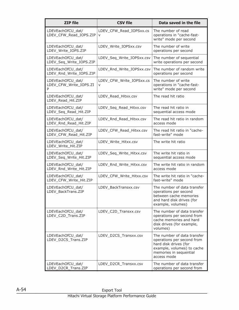
ZIP file CSV file Data saved in the file
LDEVEachOfCU_dat/LDEV_CFW_Read_IOPS.ZIP
LDEV_CFW_Read_IOPSxx.csv
The number of readoperations in "cache-fast-write" mode per second
LDEVEachOfCU_dat/LDEV_Write_IOPS.ZIP
LDEV_Write_IOPSxx.csv The number of writeoperations per second
LDEVEachOfCU_dat/LDEV_Seq_Write_IOPS.ZIP
LDEV_Seq_Write_IOPSxx.csv The number of sequentialwrite operations per second
LDEVEachOfCU_dat/LDEV_Rnd_Write_IOPS.ZIP
LDEV_Rnd_Write_IOPSxx.csv The number of random writeoperations per second
LDEVEachOfCU_dat/LDEV_CFW_Write_IOPS.ZIP
LDEV_CFW_Write_IOPSxx.csv
The number of writeoperations in "cache-fast-write" mode per second
LDEVEachOfCU_dat/LDEV_Read_Hit.ZIP
LDEV_Read_Hitxx.csv The read hit ratio
LDEVEachOfCU_dat/LDEV_Seq_Read_Hit.ZIP
LDEV_Seq_Read_Hitxx.csv The read hit ratio insequential access mode
LDEVEachOfCU_dat/LDEV_Rnd_Read_Hit.ZIP
LDEV_Rnd_Read_Hitxx.csv The read hit ratio in randomaccess mode
LDEVEachOfCU_dat/LDEV_CFW_Read_Hit.ZIP
LDEV_CFW_Read_Hitxx.csv The read hit ratio in "cache-fast-write" mode
LDEVEachOfCU_dat/LDEV_Write_Hit.ZIP
LDEV_Write_Hitxx.csv The write hit ratio
LDEVEachOfCU_dat/LDEV_Seq_Write_Hit.ZIP
LDEV_Seq_Write_Hitxx.csv The write hit ratio insequential access mode
LDEVEachOfCU_dat/LDEV_Rnd_Write_Hit.ZIP
LDEV_Rnd_Write_Hitxx.csv The write hit ratio in randomaccess mode
LDEVEachOfCU_dat/LDEV_CFW_Write_Hit.ZIP
LDEV_CFW_Write_Hitxx.csv The write hit ratio in "cache-fast-write" mode
LDEVEachOfCU_dat/LDEV_BackTrans.ZIP
LDEV_BackTransxx.csv The number of data transferoperations per secondbetween cache memoriesand hard disk drives (forexample, volumes)
LDEVEachOfCU_dat/LDEV_C2D_Trans.ZIP
LDEV_C2D_Transxx.csv The number of data transferoperations per second fromcache memories and harddisk drives (for example,volumes)
LDEVEachOfCU_dat/LDEV_D2CS_Trans.ZIP
LDEV_D2CS_Transxx.csv The number of data transferoperations per second fromhard disk drives (forexample, volumes) to cachememories in sequentialaccess mode
LDEVEachOfCU_dat/LDEV_D2CR_Trans.ZIP
LDEV_D2CR_Transxx.csv The number of data transferoperations per second from
A-54 Export ToolHitachi Virtual Storage Platform Performance Guide
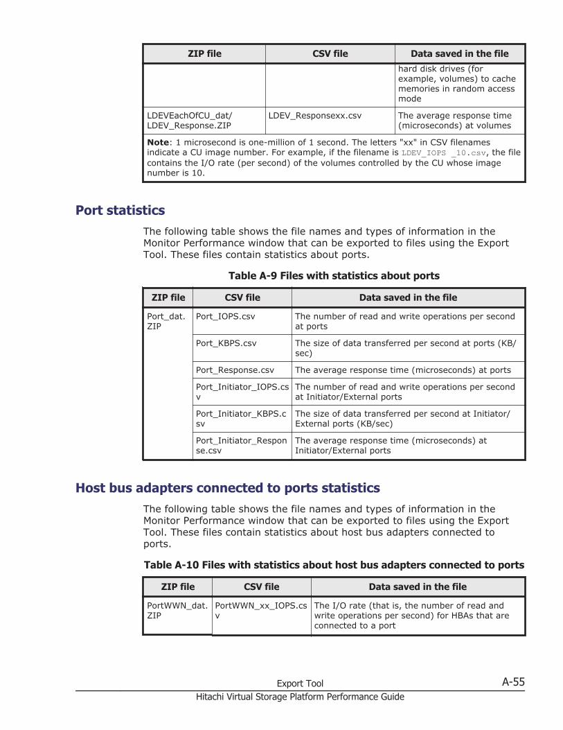
ZIP file CSV file Data saved in the file
hard disk drives (forexample, volumes) to cachememories in random accessmode
LDEVEachOfCU_dat/LDEV_Response.ZIP
LDEV_Responsexx.csv The average response time(microseconds) at volumes
Note: 1 microsecond is one-million of 1 second. The letters "xx" in CSV filenamesindicate a CU image number. For example, if the filename is LDEV_IOPS _10.csv, the filecontains the I/O rate (per second) of the volumes controlled by the CU whose imagenumber is 10.
Port statisticsThe following table shows the file names and types of information in theMonitor Performance window that can be exported to files using the ExportTool. These files contain statistics about ports.
Table A-9 Files with statistics about ports
ZIP file CSV file Data saved in the file
Port_dat.ZIP
Port_IOPS.csv The number of read and write operations per secondat ports
Port_KBPS.csv The size of data transferred per second at ports (KB/sec)
Port_Response.csv The average response time (microseconds) at ports
Port_Initiator_IOPS.csv
The number of read and write operations per secondat Initiator/External ports
Port_Initiator_KBPS.csv
The size of data transferred per second at Initiator/External ports (KB/sec)
Port_Initiator_Response.csv
The average response time (microseconds) atInitiator/External ports
Host bus adapters connected to ports statisticsThe following table shows the file names and types of information in theMonitor Performance window that can be exported to files using the ExportTool. These files contain statistics about host bus adapters connected toports.
Table A-10 Files with statistics about host bus adapters connected to ports
ZIP file CSV file Data saved in the file
PortWWN_dat.ZIP
PortWWN_xx_IOPS.csv
The I/O rate (that is, the number of read andwrite operations per second) for HBAs that areconnected to a port
Export Tool A-55Hitachi Virtual Storage Platform Performance Guide
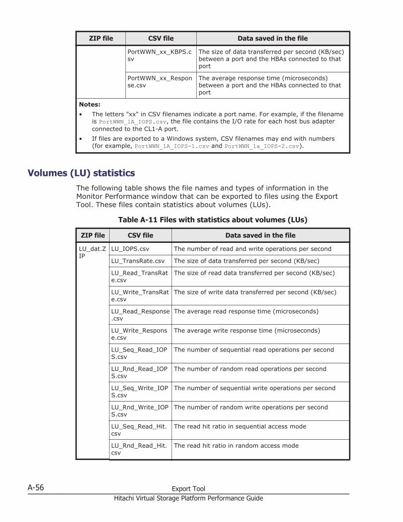
ZIP file CSV file Data saved in the file
PortWWN_xx_KBPS.csv
The size of data transferred per second (KB/sec)between a port and the HBAs connected to thatport
PortWWN_xx_Response.csv
The average response time (microseconds)between a port and the HBAs connected to thatport
Notes:• The letters "xx" in CSV filenames indicate a port name. For example, if the filename
is PortWWN_1A_IOPS.csv, the file contains the I/O rate for each host bus adapterconnected to the CL1-A port.
• If files are exported to a Windows system, CSV filenames may end with numbers(for example, PortWWN_1A_IOPS-1.csv and PortWWN_1a_IOPS-2.csv).
Volumes (LU) statisticsThe following table shows the file names and types of information in theMonitor Performance window that can be exported to files using the ExportTool. These files contain statistics about volumes (LUs).
Table A-11 Files with statistics about volumes (LUs)
ZIP file CSV file Data saved in the file
LU_dat.ZIP
LU_IOPS.csv The number of read and write operations per second
LU_TransRate.csv The size of data transferred per second (KB/sec)
LU_Read_TransRate.csv
The size of read data transferred per second (KB/sec)
LU_Write_TransRate.csv
The size of write data transferred per second (KB/sec)
LU_Read_Response.csv
The average read response time (microseconds)
LU_Write_Response.csv
The average write response time (microseconds)
LU_Seq_Read_IOPS.csv
The number of sequential read operations per second
LU_Rnd_Read_IOPS.csv
The number of random read operations per second
LU_Seq_Write_IOPS.csv
The number of sequential write operations per second
LU_Rnd_Write_IOPS.csv
The number of random write operations per second
LU_Seq_Read_Hit.csv
The read hit ratio in sequential access mode
LU_Rnd_Read_Hit.csv
The read hit ratio in random access mode
A-56 Export ToolHitachi Virtual Storage Platform Performance Guide
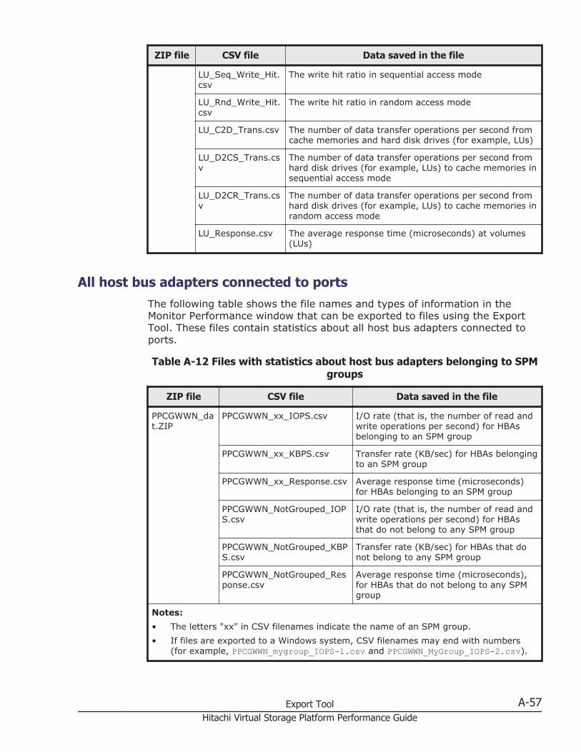
ZIP file CSV file Data saved in the file
LU_Seq_Write_Hit.csv
The write hit ratio in sequential access mode
LU_Rnd_Write_Hit.csv
The write hit ratio in random access mode
LU_C2D_Trans.csv The number of data transfer operations per second fromcache memories and hard disk drives (for example, LUs)
LU_D2CS_Trans.csv
The number of data transfer operations per second fromhard disk drives (for example, LUs) to cache memories insequential access mode
LU_D2CR_Trans.csv
The number of data transfer operations per second fromhard disk drives (for example, LUs) to cache memories inrandom access mode
LU_Response.csv The average response time (microseconds) at volumes(LUs)
All host bus adapters connected to portsThe following table shows the file names and types of information in theMonitor Performance window that can be exported to files using the ExportTool. These files contain statistics about all host bus adapters connected toports.
Table A-12 Files with statistics about host bus adapters belonging to SPMgroups
ZIP file CSV file Data saved in the file
PPCGWWN_dat.ZIP
PPCGWWN_xx_IOPS.csv I/O rate (that is, the number of read andwrite operations per second) for HBAsbelonging to an SPM group
PPCGWWN_xx_KBPS.csv Transfer rate (KB/sec) for HBAs belongingto an SPM group
PPCGWWN_xx_Response.csv Average response time (microseconds)for HBAs belonging to an SPM group
PPCGWWN_NotGrouped_IOPS.csv
I/O rate (that is, the number of read andwrite operations per second) for HBAsthat do not belong to any SPM group
PPCGWWN_NotGrouped_KBPS.csv
Transfer rate (KB/sec) for HBAs that donot belong to any SPM group
PPCGWWN_NotGrouped_Response.csv
Average response time (microseconds),for HBAs that do not belong to any SPMgroup
Notes:• The letters "xx" in CSV filenames indicate the name of an SPM group.• If files are exported to a Windows system, CSV filenames may end with numbers
(for example, PPCGWWN_mygroup_IOPS-1.csv and PPCGWWN_MyGroup_IOPS-2.csv).
Export Tool A-57Hitachi Virtual Storage Platform Performance Guide
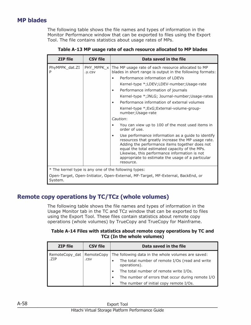
MP bladesThe following table shows the file names and types of information in theMonitor Performance window that can be exported to files using the ExportTool. The file contains statistics about usage rates of MPs.
Table A-13 MP usage rate of each resource allocated to MP blades
ZIP file CSV file Data saved in the file
PhyMPPK_dat.ZIP
PHY_MPPK_x.y.csv
The MP usage rate of each resource allocated to MPblades in short range is output in the following formats:• Performance information of LDEVs
Kernel-type *;LDEV;LDEV-number;Usage-rate• Performance information of journals
Kernel-type *;JNLG; Journal-number;Usage-rates• Performance information of external volumes
Kernel-type *;ExG;External-volume-group-number;Usage-rate
Caution:• You can view up to 100 of the most used items in
order of use.• Use performance information as a guide to identify
resources that greatly increase the MP usage rate.Adding the performance items together does notequal the total estimated capacity of the MPs.Likewise, this performance information is notappropriate to estimate the usage of a particularresource.
* The kernel type is any one of the following types:Open-Target, Open-Initiator, Open-External, MF-Target, MF-External, BackEnd, orSystem.
Remote copy operations by TC/TCz (whole volumes)The following table shows the file names and types of information in theUsage Monitor tab in the TC and TCz window that can be exported to filesusing the Export Tool. These files contain statistics about remote copyoperations (whole volumes) by TrueCopy and TrueCopy for Mainframe.
Table A-14 Files with statistics about remote copy operations by TC andTCz (In the whole volumes)
ZIP file CSV file Data saved in the file
RemoteCopy_dat.ZIP
RemoteCopy.csv
The following data in the whole volumes are saved:• The total number of remote I/Os (read and write
operations).• The total number of remote write I/Os.• The number of errors that occur during remote I/O• The number of initial copy remote I/Os.
A-58 Export ToolHitachi Virtual Storage Platform Performance Guide
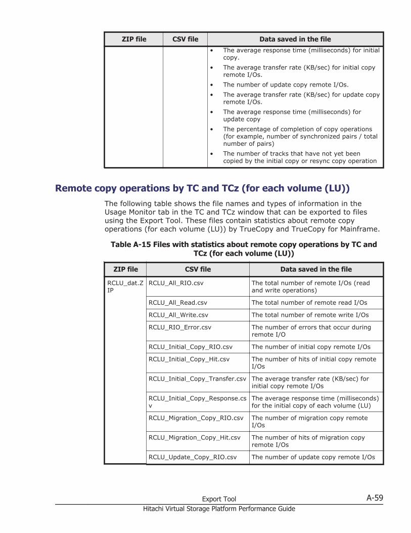
ZIP file CSV file Data saved in the file
• The average response time (milliseconds) for initialcopy.
• The average transfer rate (KB/sec) for initial copyremote I/Os.
• The number of update copy remote I/Os.• The average transfer rate (KB/sec) for update copy
remote I/Os.• The average response time (milliseconds) for
update copy• The percentage of completion of copy operations
(for example, number of synchronized pairs / totalnumber of pairs)
• The number of tracks that have not yet beencopied by the initial copy or resync copy operation
Remote copy operations by TC and TCz (for each volume (LU))The following table shows the file names and types of information in theUsage Monitor tab in the TC and TCz window that can be exported to filesusing the Export Tool. These files contain statistics about remote copyoperations (for each volume (LU)) by TrueCopy and TrueCopy for Mainframe.
Table A-15 Files with statistics about remote copy operations by TC andTCz (for each volume (LU))
ZIP file CSV file Data saved in the file
RCLU_dat.ZIP
RCLU_All_RIO.csv The total number of remote I/Os (readand write operations)
RCLU_All_Read.csv The total number of remote read I/Os
RCLU_All_Write.csv The total number of remote write I/Os
RCLU_RIO_Error.csv The number of errors that occur duringremote I/O
RCLU_Initial_Copy_RIO.csv The number of initial copy remote I/Os
RCLU_Initial_Copy_Hit.csv The number of hits of initial copy remoteI/Os
RCLU_Initial_Copy_Transfer.csv The average transfer rate (KB/sec) forinitial copy remote I/Os
RCLU_Initial_Copy_Response.csv
The average response time (milliseconds)for the initial copy of each volume (LU)
RCLU_Migration_Copy_RIO.csv The number of migration copy remoteI/Os
RCLU_Migration_Copy_Hit.csv The number of hits of migration copyremote I/Os
RCLU_Update_Copy_RIO.csv The number of update copy remote I/Os
Export Tool A-59Hitachi Virtual Storage Platform Performance Guide
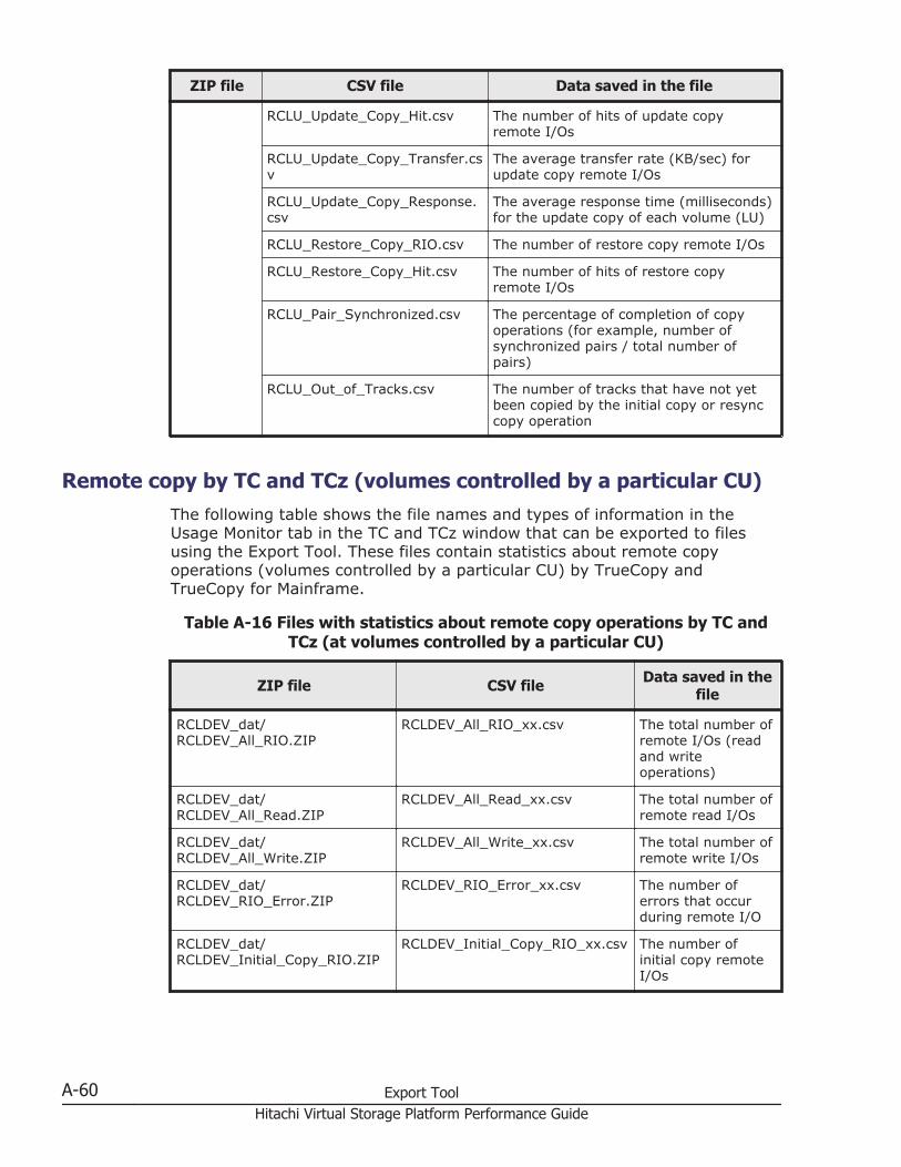
ZIP file CSV file Data saved in the file
RCLU_Update_Copy_Hit.csv The number of hits of update copyremote I/Os
RCLU_Update_Copy_Transfer.csv
The average transfer rate (KB/sec) forupdate copy remote I/Os
RCLU_Update_Copy_Response.csv
The average response time (milliseconds)for the update copy of each volume (LU)
RCLU_Restore_Copy_RIO.csv The number of restore copy remote I/Os
RCLU_Restore_Copy_Hit.csv The number of hits of restore copyremote I/Os
RCLU_Pair_Synchronized.csv The percentage of completion of copyoperations (for example, number ofsynchronized pairs / total number ofpairs)
RCLU_Out_of_Tracks.csv The number of tracks that have not yetbeen copied by the initial copy or resynccopy operation
Remote copy by TC and TCz (volumes controlled by a particular CU)The following table shows the file names and types of information in theUsage Monitor tab in the TC and TCz window that can be exported to filesusing the Export Tool. These files contain statistics about remote copyoperations (volumes controlled by a particular CU) by TrueCopy andTrueCopy for Mainframe.
Table A-16 Files with statistics about remote copy operations by TC andTCz (at volumes controlled by a particular CU)
ZIP file CSV file Data saved in thefile
RCLDEV_dat/RCLDEV_All_RIO.ZIP
RCLDEV_All_RIO_xx.csv The total number ofremote I/Os (readand writeoperations)
RCLDEV_dat/RCLDEV_All_Read.ZIP
RCLDEV_All_Read_xx.csv The total number ofremote read I/Os
RCLDEV_dat/RCLDEV_All_Write.ZIP
RCLDEV_All_Write_xx.csv The total number ofremote write I/Os
RCLDEV_dat/RCLDEV_RIO_Error.ZIP
RCLDEV_RIO_Error_xx.csv The number oferrors that occurduring remote I/O
RCLDEV_dat/RCLDEV_Initial_Copy_RIO.ZIP
RCLDEV_Initial_Copy_RIO_xx.csv The number ofinitial copy remoteI/Os
A-60 Export ToolHitachi Virtual Storage Platform Performance Guide
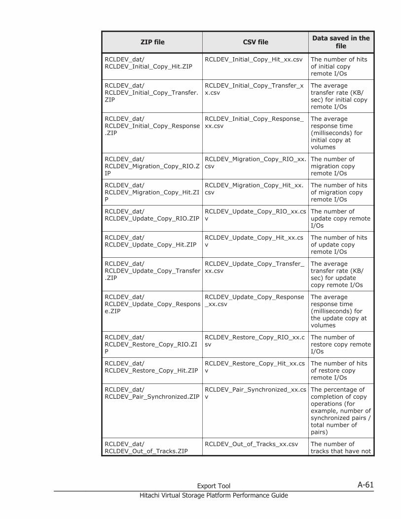
ZIP file CSV file Data saved in thefile
RCLDEV_dat/RCLDEV_Initial_Copy_Hit.ZIP
RCLDEV_Initial_Copy_Hit_xx.csv The number of hitsof initial copyremote I/Os
RCLDEV_dat/RCLDEV_Initial_Copy_Transfer.ZIP
RCLDEV_Initial_Copy_Transfer_xx.csv
The averagetransfer rate (KB/sec) for initial copyremote I/Os
RCLDEV_dat/RCLDEV_Initial_Copy_Response.ZIP
RCLDEV_Initial_Copy_Response_xx.csv
The averageresponse time(milliseconds) forinitial copy atvolumes
RCLDEV_dat/RCLDEV_Migration_Copy_RIO.ZIP
RCLDEV_Migration_Copy_RIO_xx.csv
The number ofmigration copyremote I/Os
RCLDEV_dat/RCLDEV_Migration_Copy_Hit.ZIP
RCLDEV_Migration_Copy_Hit_xx.csv
The number of hitsof migration copyremote I/Os
RCLDEV_dat/RCLDEV_Update_Copy_RIO.ZIP
RCLDEV_Update_Copy_RIO_xx.csv
The number ofupdate copy remoteI/Os
RCLDEV_dat/RCLDEV_Update_Copy_Hit.ZIP
RCLDEV_Update_Copy_Hit_xx.csv
The number of hitsof update copyremote I/Os
RCLDEV_dat/RCLDEV_Update_Copy_Transfer.ZIP
RCLDEV_Update_Copy_Transfer_xx.csv
The averagetransfer rate (KB/sec) for updatecopy remote I/Os
RCLDEV_dat/RCLDEV_Update_Copy_Response.ZIP
RCLDEV_Update_Copy_Response_xx.csv
The averageresponse time(milliseconds) forthe update copy atvolumes
RCLDEV_dat/RCLDEV_Restore_Copy_RIO.ZIP
RCLDEV_Restore_Copy_RIO_xx.csv
The number ofrestore copy remoteI/Os
RCLDEV_dat/RCLDEV_Restore_Copy_Hit.ZIP
RCLDEV_Restore_Copy_Hit_xx.csv
The number of hitsof restore copyremote I/Os
RCLDEV_dat/RCLDEV_Pair_Synchronized.ZIP
RCLDEV_Pair_Synchronized_xx.csv
The percentage ofcompletion of copyoperations (forexample, number ofsynchronized pairs /total number ofpairs)
RCLDEV_dat/RCLDEV_Out_of_Tracks.ZIP
RCLDEV_Out_of_Tracks_xx.csv The number oftracks that have not
Export Tool A-61Hitachi Virtual Storage Platform Performance Guide
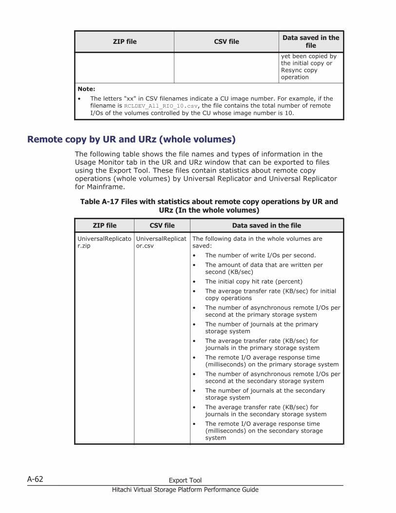
ZIP file CSV file Data saved in thefile
yet been copied bythe initial copy orResync copyoperation
Note:• The letters "xx" in CSV filenames indicate a CU image number. For example, if the
filename is RCLDEV_All_RIO_10.csv, the file contains the total number of remoteI/Os of the volumes controlled by the CU whose image number is 10.
Remote copy by UR and URz (whole volumes)The following table shows the file names and types of information in theUsage Monitor tab in the UR and URz window that can be exported to filesusing the Export Tool. These files contain statistics about remote copyoperations (whole volumes) by Universal Replicator and Universal Replicatorfor Mainframe.
Table A-17 Files with statistics about remote copy operations by UR andURz (In the whole volumes)
ZIP file CSV file Data saved in the file
UniversalReplicator.zip
UniversalReplicator.csv
The following data in the whole volumes aresaved:• The number of write I/Os per second.• The amount of data that are written per
second (KB/sec)• The initial copy hit rate (percent)• The average transfer rate (KB/sec) for initial
copy operations• The number of asynchronous remote I/Os per
second at the primary storage system• The number of journals at the primary
storage system• The average transfer rate (KB/sec) for
journals in the primary storage system• The remote I/O average response time
(milliseconds) on the primary storage system• The number of asynchronous remote I/Os per
second at the secondary storage system• The number of journals at the secondary
storage system• The average transfer rate (KB/sec) for
journals in the secondary storage system• The remote I/O average response time
(milliseconds) on the secondary storagesystem
A-62 Export ToolHitachi Virtual Storage Platform Performance Guide
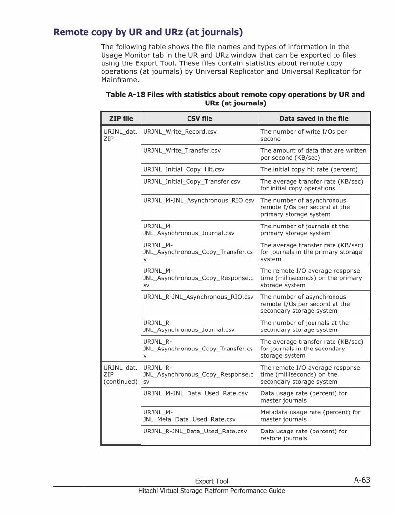
Remote copy by UR and URz (at journals)The following table shows the file names and types of information in theUsage Monitor tab in the UR and URz window that can be exported to filesusing the Export Tool. These files contain statistics about remote copyoperations (at journals) by Universal Replicator and Universal Replicator forMainframe.
Table A-18 Files with statistics about remote copy operations by UR andURz (at journals)
ZIP file CSV file Data saved in the file
URJNL_dat.ZIP
URJNL_Write_Record.csv The number of write I/Os persecond
URJNL_Write_Transfer.csv The amount of data that are writtenper second (KB/sec)
URJNL_Initial_Copy_Hit.csv The initial copy hit rate (percent)
URJNL_Initial_Copy_Transfer.csv The average transfer rate (KB/sec)for initial copy operations
URJNL_M-JNL_Asynchronous_RIO.csv The number of asynchronousremote I/Os per second at theprimary storage system
URJNL_M-JNL_Asynchronous_Journal.csv
The number of journals at theprimary storage system
URJNL_M-JNL_Asynchronous_Copy_Transfer.csv
The average transfer rate (KB/sec)for journals in the primary storagesystem
URJNL_M-JNL_Asynchronous_Copy_Response.csv
The remote I/O average responsetime (milliseconds) on the primarystorage system
URJNL_R-JNL_Asynchronous_RIO.csv The number of asynchronousremote I/Os per second at thesecondary storage system
URJNL_R-JNL_Asynchronous_Journal.csv
The number of journals at thesecondary storage system
URJNL_R-JNL_Asynchronous_Copy_Transfer.csv
The average transfer rate (KB/sec)for journals in the secondarystorage system
URJNL_dat.ZIP(continued)
URJNL_R-JNL_Asynchronous_Copy_Response.csv
The remote I/O average responsetime (milliseconds) on thesecondary storage system
URJNL_M-JNL_Data_Used_Rate.csv Data usage rate (percent) formaster journals
URJNL_M-JNL_Meta_Data_Used_Rate.csv
Metadata usage rate (percent) formaster journals
URJNL_R-JNL_Data_Used_Rate.csv Data usage rate (percent) forrestore journals
Export Tool A-63Hitachi Virtual Storage Platform Performance Guide
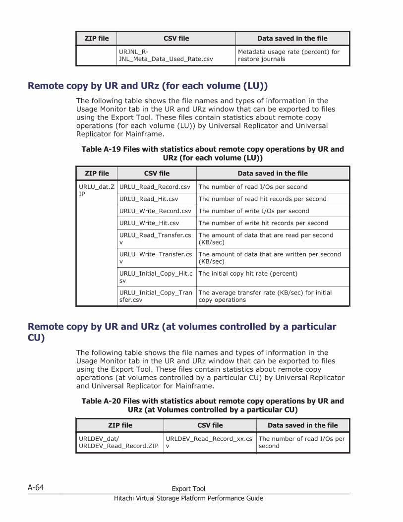
ZIP file CSV file Data saved in the file
URJNL_R-JNL_Meta_Data_Used_Rate.csv
Metadata usage rate (percent) forrestore journals
Remote copy by UR and URz (for each volume (LU))The following table shows the file names and types of information in theUsage Monitor tab in the UR and URz window that can be exported to filesusing the Export Tool. These files contain statistics about remote copyoperations (for each volume (LU)) by Universal Replicator and UniversalReplicator for Mainframe.
Table A-19 Files with statistics about remote copy operations by UR andURz (for each volume (LU))
ZIP file CSV file Data saved in the file
URLU_dat.ZIP
URLU_Read_Record.csv The number of read I/Os per second
URLU_Read_Hit.csv The number of read hit records per second
URLU_Write_Record.csv The number of write I/Os per second
URLU_Write_Hit.csv The number of write hit records per second
URLU_Read_Transfer.csv
The amount of data that are read per second(KB/sec)
URLU_Write_Transfer.csv
The amount of data that are written per second(KB/sec)
URLU_Initial_Copy_Hit.csv
The initial copy hit rate (percent)
URLU_Initial_Copy_Transfer.csv
The average transfer rate (KB/sec) for initialcopy operations
Remote copy by UR and URz (at volumes controlled by a particularCU)
The following table shows the file names and types of information in theUsage Monitor tab in the UR and URz window that can be exported to filesusing the Export Tool. These files contain statistics about remote copyoperations (at volumes controlled by a particular CU) by Universal Replicatorand Universal Replicator for Mainframe.
Table A-20 Files with statistics about remote copy operations by UR andURz (at Volumes controlled by a particular CU)
ZIP file CSV file Data saved in the file
URLDEV_dat/URLDEV_Read_Record.ZIP
URLDEV_Read_Record_xx.csv
The number of read I/Os persecond
A-64 Export ToolHitachi Virtual Storage Platform Performance Guide
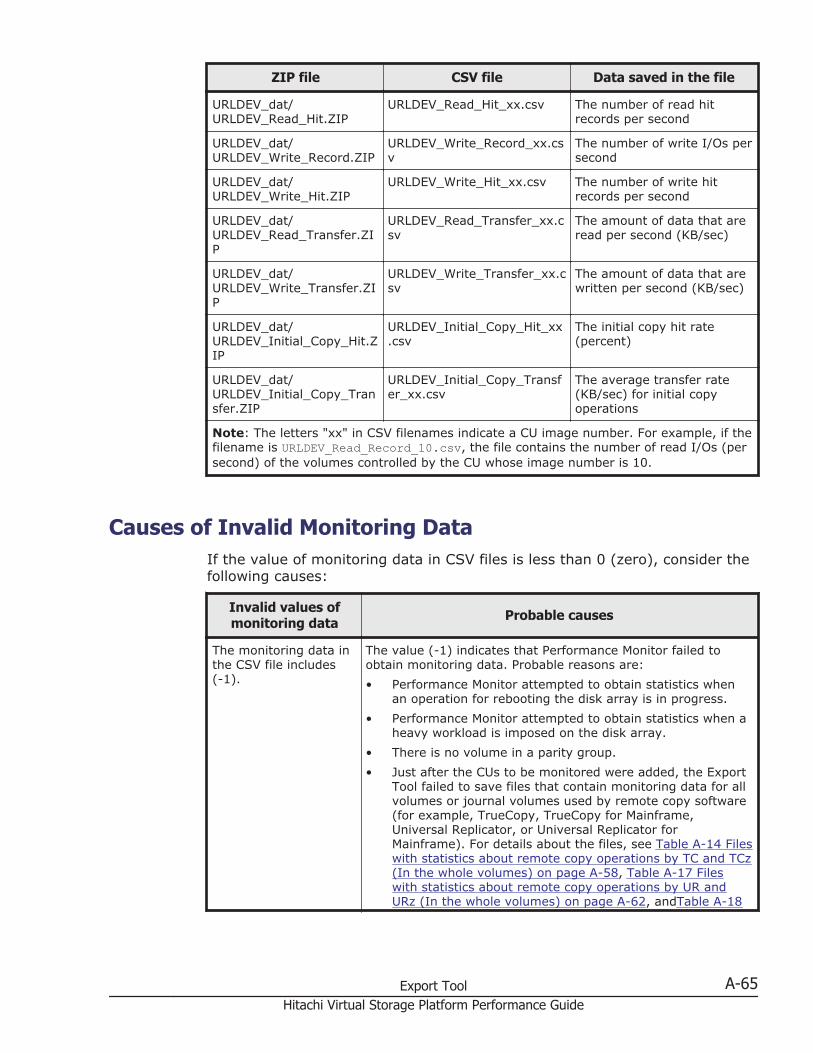
ZIP file CSV file Data saved in the file
URLDEV_dat/URLDEV_Read_Hit.ZIP
URLDEV_Read_Hit_xx.csv The number of read hitrecords per second
URLDEV_dat/URLDEV_Write_Record.ZIP
URLDEV_Write_Record_xx.csv
The number of write I/Os persecond
URLDEV_dat/URLDEV_Write_Hit.ZIP
URLDEV_Write_Hit_xx.csv The number of write hitrecords per second
URLDEV_dat/URLDEV_Read_Transfer.ZIP
URLDEV_Read_Transfer_xx.csv
The amount of data that areread per second (KB/sec)
URLDEV_dat/URLDEV_Write_Transfer.ZIP
URLDEV_Write_Transfer_xx.csv
The amount of data that arewritten per second (KB/sec)
URLDEV_dat/URLDEV_Initial_Copy_Hit.ZIP
URLDEV_Initial_Copy_Hit_xx.csv
The initial copy hit rate(percent)
URLDEV_dat/URLDEV_Initial_Copy_Transfer.ZIP
URLDEV_Initial_Copy_Transfer_xx.csv
The average transfer rate(KB/sec) for initial copyoperations
Note: The letters "xx" in CSV filenames indicate a CU image number. For example, if thefilename is URLDEV_Read_Record_10.csv, the file contains the number of read I/Os (persecond) of the volumes controlled by the CU whose image number is 10.
Causes of Invalid Monitoring DataIf the value of monitoring data in CSV files is less than 0 (zero), consider thefollowing causes:
Invalid values ofmonitoring data Probable causes
The monitoring data inthe CSV file includes(-1).
The value (-1) indicates that Performance Monitor failed toobtain monitoring data. Probable reasons are:• Performance Monitor attempted to obtain statistics when
an operation for rebooting the disk array is in progress.• Performance Monitor attempted to obtain statistics when a
heavy workload is imposed on the disk array.• There is no volume in a parity group.• Just after the CUs to be monitored were added, the Export
Tool failed to save files that contain monitoring data for allvolumes or journal volumes used by remote copy software(for example, TrueCopy, TrueCopy for Mainframe,Universal Replicator, or Universal Replicator forMainframe). For details about the files, see Table A-14 Fileswith statistics about remote copy operations by TC and TCz(In the whole volumes) on page A-58, Table A-17 Fileswith statistics about remote copy operations by UR andURz (In the whole volumes) on page A-62, andTable A-18
Export Tool A-65Hitachi Virtual Storage Platform Performance Guide
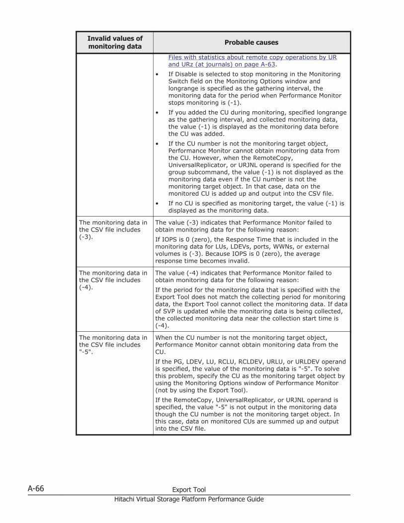
Invalid values ofmonitoring data Probable causes
Files with statistics about remote copy operations by URand URz (at journals) on page A-63.
• If Disable is selected to stop monitoring in the MonitoringSwitch field on the Monitoring Options window andlongrange is specified as the gathering interval, themonitoring data for the period when Performance Monitorstops monitoring is (-1).
• If you added the CU during monitoring, specified longrangeas the gathering interval, and collected monitoring data,the value (-1) is displayed as the monitoring data beforethe CU was added.
• If the CU number is not the monitoring target object,Performance Monitor cannot obtain monitoring data fromthe CU. However, when the RemoteCopy,UniversalReplicator, or URJNL operand is specified for thegroup subcommand, the value (-1) is not displayed as themonitoring data even if the CU number is not themonitoring target object. In that case, data on themonitored CU is added up and output into the CSV file.
• If no CU is specified as monitoring target, the value (-1) isdisplayed as the monitoring data.
The monitoring data inthe CSV file includes(-3).
The value (-3) indicates that Performance Monitor failed toobtain monitoring data for the following reason:If IOPS is 0 (zero), the Response Time that is included in themonitoring data for LUs, LDEVs, ports, WWNs, or externalvolumes is (-3). Because IOPS is 0 (zero), the averageresponse time becomes invalid.
The monitoring data inthe CSV file includes(-4).
The value (-4) indicates that Performance Monitor failed toobtain monitoring data for the following reason:If the period for the monitoring data that is specified with theExport Tool does not match the collecting period for monitoringdata, the Export Tool cannot collect the monitoring data. If dataof SVP is updated while the monitoring data is being collected,the collected monitoring data near the collection start time is(-4).
The monitoring data inthe CSV file includes"-5".
When the CU number is not the monitoring target object,Performance Monitor cannot obtain monitoring data from theCU.If the PG, LDEV, LU, RCLU, RCLDEV, URLU, or URLDEV operandis specified, the value of the monitoring data is "-5". To solvethis problem, specify the CU as the monitoring target object byusing the Monitoring Options window of Performance Monitor(not by using the Export Tool).If the RemoteCopy, UniversalReplicator, or URJNL operand isspecified, the value "-5" is not output in the monitoring datathough the CU number is not the monitoring target object. Inthis case, data on monitored CUs are summed up and outputinto the CSV file.
A-66 Export ToolHitachi Virtual Storage Platform Performance Guide
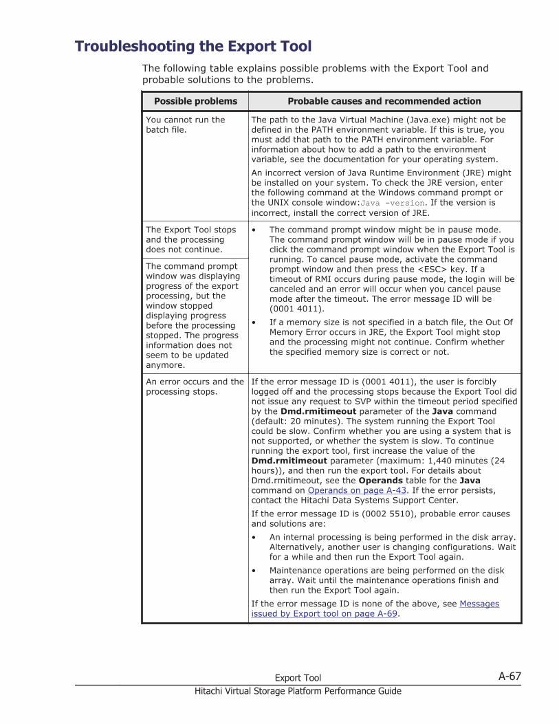
Troubleshooting the Export ToolThe following table explains possible problems with the Export Tool andprobable solutions to the problems.
Possible problems Probable causes and recommended action
You cannot run thebatch file.
The path to the Java Virtual Machine (Java.exe) might not bedefined in the PATH environment variable. If this is true, youmust add that path to the PATH environment variable. Forinformation about how to add a path to the environmentvariable, see the documentation for your operating system.An incorrect version of Java Runtime Environment (JRE) mightbe installed on your system. To check the JRE version, enterthe following command at the Windows command prompt orthe UNIX console window:Java -version. If the version isincorrect, install the correct version of JRE.
The Export Tool stopsand the processingdoes not continue.
• The command prompt window might be in pause mode.The command prompt window will be in pause mode if youclick the command prompt window when the Export Tool isrunning. To cancel pause mode, activate the commandprompt window and then press the <ESC> key. If atimeout of RMI occurs during pause mode, the login will becanceled and an error will occur when you cancel pausemode after the timeout. The error message ID will be(0001 4011).
• If a memory size is not specified in a batch file, the Out OfMemory Error occurs in JRE, the Export Tool might stopand the processing might not continue. Confirm whetherthe specified memory size is correct or not.
The command promptwindow was displayingprogress of the exportprocessing, but thewindow stoppeddisplaying progressbefore the processingstopped. The progressinformation does notseem to be updatedanymore.
An error occurs and theprocessing stops.
If the error message ID is (0001 4011), the user is forciblylogged off and the processing stops because the Export Tool didnot issue any request to SVP within the timeout period specifiedby the Dmd.rmitimeout parameter of the Java command(default: 20 minutes). The system running the Export Toolcould be slow. Confirm whether you are using a system that isnot supported, or whether the system is slow. To continuerunning the export tool, first increase the value of theDmd.rmitimeout parameter (maximum: 1,440 minutes (24hours)), and then run the export tool. For details aboutDmd.rmitimeout, see the Operands table for the Javacommand on Operands on page A-43. If the error persists,contact the Hitachi Data Systems Support Center.If the error message ID is (0002 5510), probable error causesand solutions are:• An internal processing is being performed in the disk array.
Alternatively, another user is changing configurations. Waitfor a while and then run the Export Tool again.
• Maintenance operations are being performed on the diskarray. Wait until the maintenance operations finish andthen run the Export Tool again.
If the error message ID is none of the above, see Messagesissued by Export tool on page A-69.
Export Tool A-67Hitachi Virtual Storage Platform Performance Guide
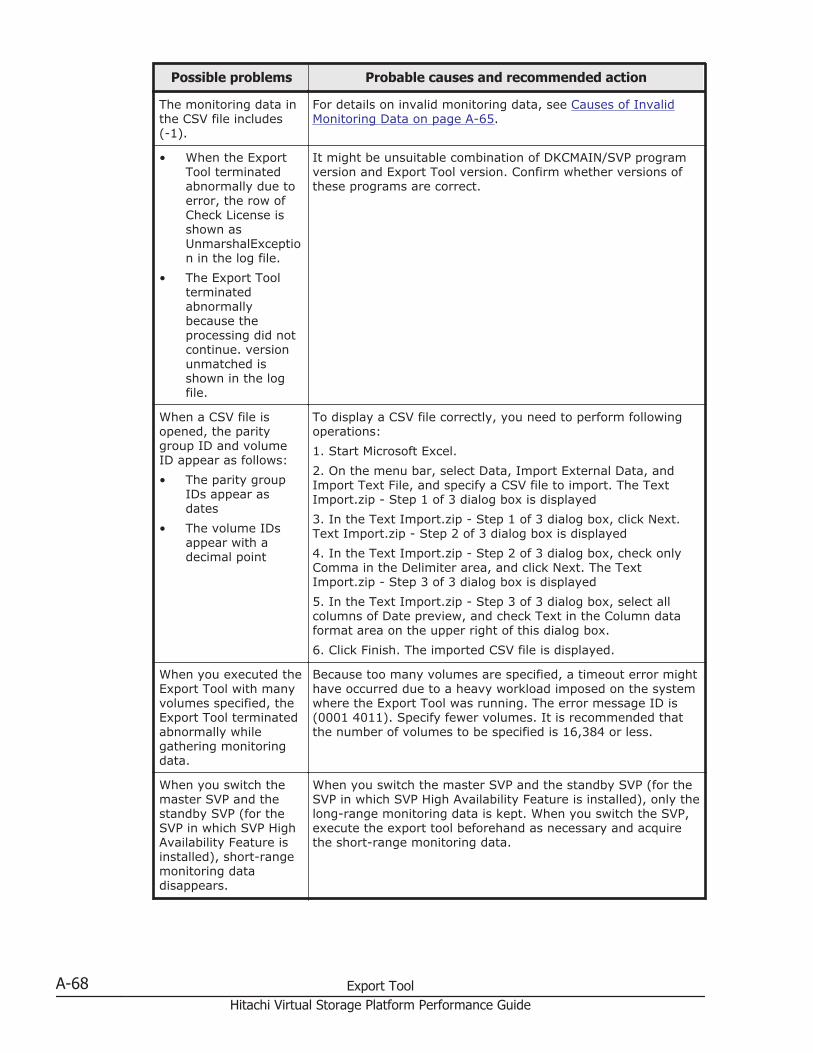
Possible problems Probable causes and recommended action
The monitoring data inthe CSV file includes(-1).
For details on invalid monitoring data, see Causes of InvalidMonitoring Data on page A-65.
• When the ExportTool terminatedabnormally due toerror, the row ofCheck License isshown asUnmarshalException in the log file.
• The Export Toolterminatedabnormallybecause theprocessing did notcontinue. versionunmatched isshown in the logfile.
It might be unsuitable combination of DKCMAIN/SVP programversion and Export Tool version. Confirm whether versions ofthese programs are correct.
When a CSV file isopened, the paritygroup ID and volumeID appear as follows:• The parity group
IDs appear asdates
• The volume IDsappear with adecimal point
To display a CSV file correctly, you need to perform followingoperations:1. Start Microsoft Excel.2. On the menu bar, select Data, Import External Data, andImport Text File, and specify a CSV file to import. The TextImport.zip - Step 1 of 3 dialog box is displayed3. In the Text Import.zip - Step 1 of 3 dialog box, click Next.Text Import.zip - Step 2 of 3 dialog box is displayed4. In the Text Import.zip - Step 2 of 3 dialog box, check onlyComma in the Delimiter area, and click Next. The TextImport.zip - Step 3 of 3 dialog box is displayed5. In the Text Import.zip - Step 3 of 3 dialog box, select allcolumns of Date preview, and check Text in the Column dataformat area on the upper right of this dialog box.6. Click Finish. The imported CSV file is displayed.
When you executed theExport Tool with manyvolumes specified, theExport Tool terminatedabnormally whilegathering monitoringdata.
Because too many volumes are specified, a timeout error mighthave occurred due to a heavy workload imposed on the systemwhere the Export Tool was running. The error message ID is(0001 4011). Specify fewer volumes. It is recommended thatthe number of volumes to be specified is 16,384 or less.
When you switch themaster SVP and thestandby SVP (for theSVP in which SVP HighAvailability Feature isinstalled), short-rangemonitoring datadisappears.
When you switch the master SVP and the standby SVP (for theSVP in which SVP High Availability Feature is installed), only thelong-range monitoring data is kept. When you switch the SVP,execute the export tool beforehand as necessary and acquirethe short-range monitoring data.
A-68 Export ToolHitachi Virtual Storage Platform Performance Guide
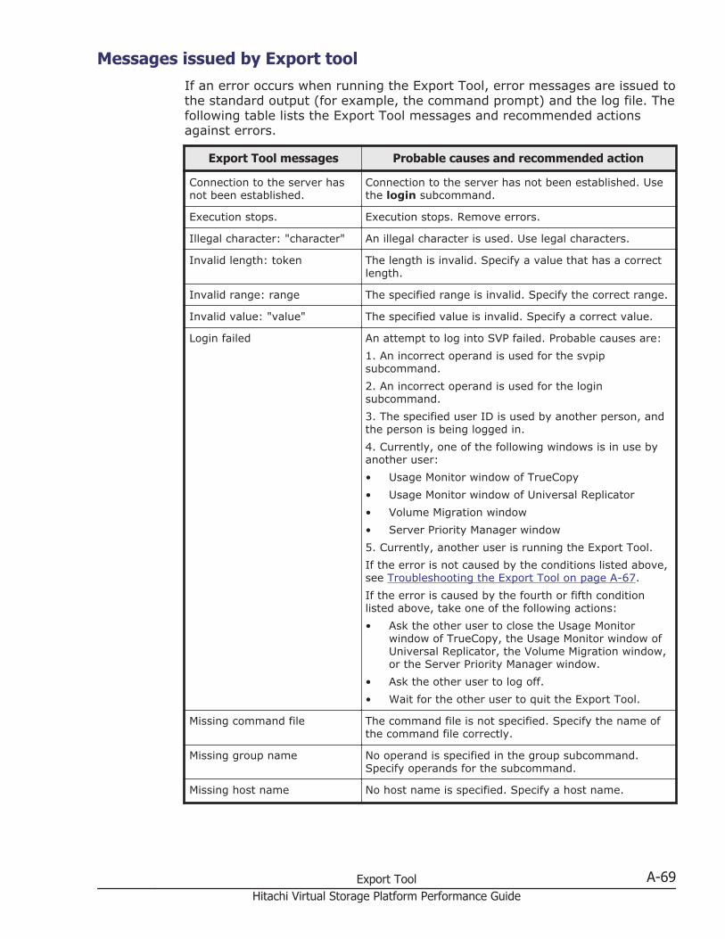
Messages issued by Export toolIf an error occurs when running the Export Tool, error messages are issued tothe standard output (for example, the command prompt) and the log file. Thefollowing table lists the Export Tool messages and recommended actionsagainst errors.
Export Tool messages Probable causes and recommended action
Connection to the server hasnot been established.
Connection to the server has not been established. Usethe login subcommand.
Execution stops. Execution stops. Remove errors.
Illegal character: "character" An illegal character is used. Use legal characters.
Invalid length: token The length is invalid. Specify a value that has a correctlength.
Invalid range: range The specified range is invalid. Specify the correct range.
Invalid value: "value" The specified value is invalid. Specify a correct value.
Login failed An attempt to log into SVP failed. Probable causes are:1. An incorrect operand is used for the svpipsubcommand.2. An incorrect operand is used for the loginsubcommand.3. The specified user ID is used by another person, andthe person is being logged in.4. Currently, one of the following windows is in use byanother user:• Usage Monitor window of TrueCopy• Usage Monitor window of Universal Replicator• Volume Migration window• Server Priority Manager window5. Currently, another user is running the Export Tool.If the error is not caused by the conditions listed above,see Troubleshooting the Export Tool on page A-67.If the error is caused by the fourth or fifth conditionlisted above, take one of the following actions:• Ask the other user to close the Usage Monitor
window of TrueCopy, the Usage Monitor window ofUniversal Replicator, the Volume Migration window,or the Server Priority Manager window.
• Ask the other user to log off.• Wait for the other user to quit the Export Tool.
Missing command file The command file is not specified. Specify the name ofthe command file correctly.
Missing group name No operand is specified in the group subcommand.Specify operands for the subcommand.
Missing host name No host name is specified. Specify a host name.
Export Tool A-69Hitachi Virtual Storage Platform Performance Guide
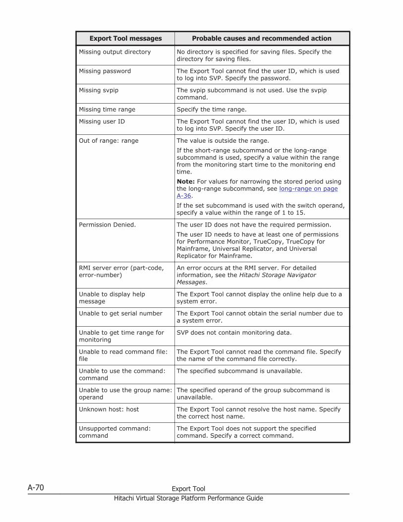
Export Tool messages Probable causes and recommended action
Missing output directory No directory is specified for saving files. Specify thedirectory for saving files.
Missing password The Export Tool cannot find the user ID, which is usedto log into SVP. Specify the password.
Missing svpip The svpip subcommand is not used. Use the svpipcommand.
Missing time range Specify the time range.
Missing user ID The Export Tool cannot find the user ID, which is usedto log into SVP. Specify the user ID.
Out of range: range The value is outside the range.If the short-range subcommand or the long-rangesubcommand is used, specify a value within the rangefrom the monitoring start time to the monitoring endtime.Note: For values for narrowing the stored period usingthe long-range subcommand, see long-range on pageA-36.If the set subcommand is used with the switch operand,specify a value within the range of 1 to 15.
Permission Denied. The user ID does not have the required permission.The user ID needs to have at least one of permissionsfor Performance Monitor, TrueCopy, TrueCopy forMainframe, Universal Replicator, and UniversalReplicator for Mainframe.
RMI server error (part-code,error-number)
An error occurs at the RMI server. For detailedinformation, see the Hitachi Storage NavigatorMessages.
Unable to display helpmessage
The Export Tool cannot display the online help due to asystem error.
Unable to get serial number The Export Tool cannot obtain the serial number due toa system error.
Unable to get time range formonitoring
SVP does not contain monitoring data.
Unable to read command file:file
The Export Tool cannot read the command file. Specifythe name of the command file correctly.
Unable to use the command:command
The specified subcommand is unavailable.
Unable to use the group name:operand
The specified operand of the group subcommand isunavailable.
Unknown host: host The Export Tool cannot resolve the host name. Specifythe correct host name.
Unsupported command:command
The Export Tool does not support the specifiedcommand. Specify a correct command.
A-70 Export ToolHitachi Virtual Storage Platform Performance Guide
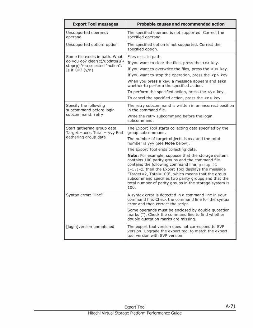
Export Tool messages Probable causes and recommended action
Unsupported operand:operand
The specified operand is not supported. Correct thespecified operand.
Unsupported option: option The specified option is not supported. Correct thespecified option.
Some file exists in path. Whatdo you do? clear(c)/update(u)/stop(p) You selected "action".Is it OK? (y/n)
Files exist in path.If you want to clear the files, press the <c> key.If you want to overwrite the files, press the <u> key.If you want to stop the operation, press the <p> key.When you press a key, a message appears and askswhether to perform the specified action.To perform the specified action, press the <y> key.To cancel the specified action, press the <n> key.
Specify the followingsubcommand before loginsubcommand: retry
The retry subcommand is written in an incorrect positionin the command file.Write the retry subcommand before the loginsubcommand.
Start gathering group dataTarget = xxx, Total = yyy Endgathering group data
The Export Tool starts collecting data specified by thegroup subcommand.The number of target objects is xxx and the totalnumber is yyy (see Note below).The Export Tool ends collecting data.Note: For example, suppose that the storage systemcontains 100 parity groups and the command filecontains the following command line: group PG1-1:1-2, then the Export Tool displays the message"Target=2, Total=100", which means that the groupsubcommand specifies two parity groups and that thetotal number of parity groups in the storage system is100.
Syntax error: "line" A syntax error is detected in a command line in yourcommand file. Check the command line for the syntaxerror and then correct the script.Some operands must be enclosed by double quotationmarks ("). Check the command line to find whetherdouble quotation marks are missing.
[login]version unmatched The export tool version does not correspond to SVPversion. Upgrade the export tool to match the exporttool version with SVP version.
Export Tool A-71Hitachi Virtual Storage Platform Performance Guide

A-72 Export ToolHitachi Virtual Storage Platform Performance Guide
BPerformance Monitor GUI reference
This topic provides reference information about the Performance Monitor GUI.
□ Performance Monitor main window
□ Edit Monitoring Switch wizard
□ Monitor Performance window
□ Edit CU Monitor Mode wizard
□ View CU Matrix window
□ Select by Parity Groups window
□ Parity Group Properties window
□ Edit WWN wizard
□ Edit WWN Monitor Mode wizard
□ Delete Unused WWNs window
□ Add New Monitored WWNs wizard
□ Add to Ports wizard
□ Monitor window
□ MP Properties window
□ Edit Time Range window
Performance Monitor GUI reference B-1Hitachi Virtual Storage Platform Performance Guide
□ Edit Performance Objects window
□ Add Graph window
□ Wizard buttons
□ Navigation buttons
B-2 Performance Monitor GUI referenceHitachi Virtual Storage Platform Performance Guide
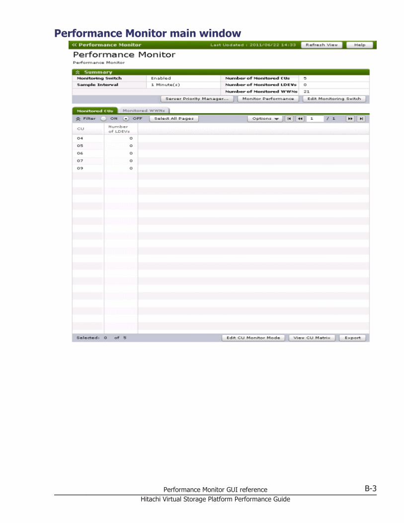
Performance Monitor main window
Performance Monitor GUI reference B-3Hitachi Virtual Storage Platform Performance Guide
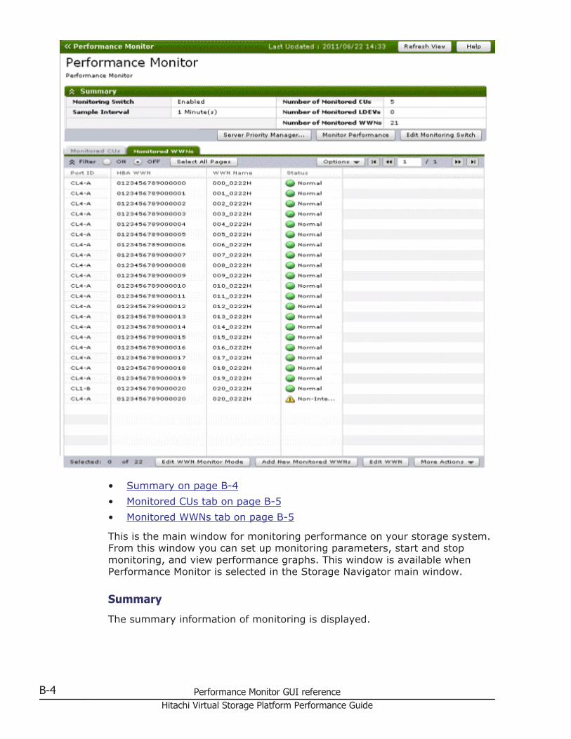
• Summary on page B-4• Monitored CUs tab on page B-5• Monitored WWNs tab on page B-5
This is the main window for monitoring performance on your storage system.From this window you can set up monitoring parameters, start and stopmonitoring, and view performance graphs. This window is available whenPerformance Monitor is selected in the Storage Navigator main window.
Summary
The summary information of monitoring is displayed.
B-4 Performance Monitor GUI referenceHitachi Virtual Storage Platform Performance Guide
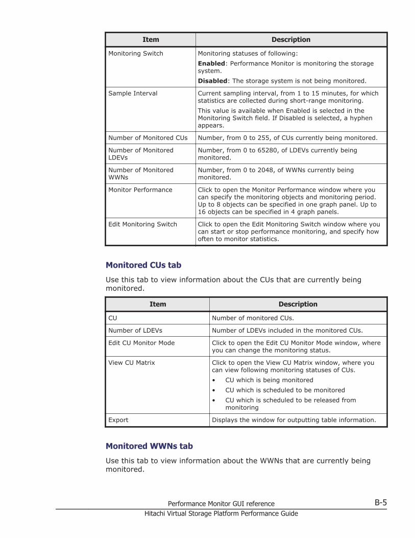
Item Description
Monitoring Switch Monitoring statuses of following:Enabled: Performance Monitor is monitoring the storagesystem.Disabled: The storage system is not being monitored.
Sample Interval Current sampling interval, from 1 to 15 minutes, for whichstatistics are collected during short-range monitoring.This value is available when Enabled is selected in theMonitoring Switch field. If Disabled is selected, a hyphenappears.
Number of Monitored CUs Number, from 0 to 255, of CUs currently being monitored.
Number of MonitoredLDEVs
Number, from 0 to 65280, of LDEVs currently beingmonitored.
Number of MonitoredWWNs
Number, from 0 to 2048, of WWNs currently beingmonitored.
Monitor Performance Click to open the Monitor Performance window where youcan specify the monitoring objects and monitoring period.Up to 8 objects can be specified in one graph panel. Up to16 objects can be specified in 4 graph panels.
Edit Monitoring Switch Click to open the Edit Monitoring Switch window where youcan start or stop performance monitoring, and specify howoften to monitor statistics.
Monitored CUs tab
Use this tab to view information about the CUs that are currently beingmonitored.
Item Description
CU Number of monitored CUs.
Number of LDEVs Number of LDEVs included in the monitored CUs.
Edit CU Monitor Mode Click to open the Edit CU Monitor Mode window, whereyou can change the monitoring status.
View CU Matrix Click to open the View CU Matrix window, where youcan view following monitoring statuses of CUs.• CU which is being monitored• CU which is scheduled to be monitored• CU which is scheduled to be released from
monitoring
Export Displays the window for outputting table information.
Monitored WWNs tab
Use this tab to view information about the WWNs that are currently beingmonitored.
Performance Monitor GUI reference B-5Hitachi Virtual Storage Platform Performance Guide
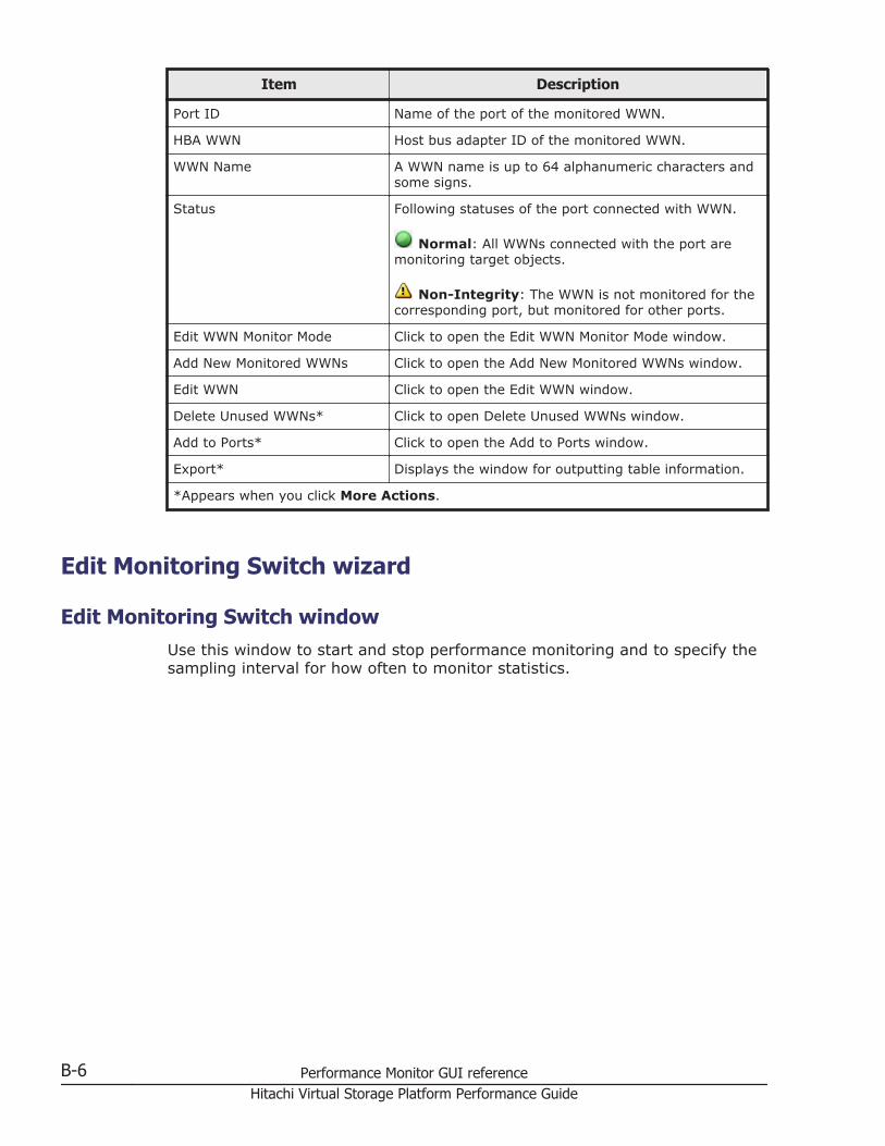
Item Description
Port ID Name of the port of the monitored WWN.
HBA WWN Host bus adapter ID of the monitored WWN.
WWN Name A WWN name is up to 64 alphanumeric characters andsome signs.
Status Following statuses of the port connected with WWN.
Normal: All WWNs connected with the port aremonitoring target objects.
Non-Integrity: The WWN is not monitored for thecorresponding port, but monitored for other ports.
Edit WWN Monitor Mode Click to open the Edit WWN Monitor Mode window.
Add New Monitored WWNs Click to open the Add New Monitored WWNs window.
Edit WWN Click to open the Edit WWN window.
Delete Unused WWNs* Click to open Delete Unused WWNs window.
Add to Ports* Click to open the Add to Ports window.
Export* Displays the window for outputting table information.
*Appears when you click More Actions.
Edit Monitoring Switch wizard
Edit Monitoring Switch windowUse this window to start and stop performance monitoring and to specify thesampling interval for how often to monitor statistics.
B-6 Performance Monitor GUI referenceHitachi Virtual Storage Platform Performance Guide
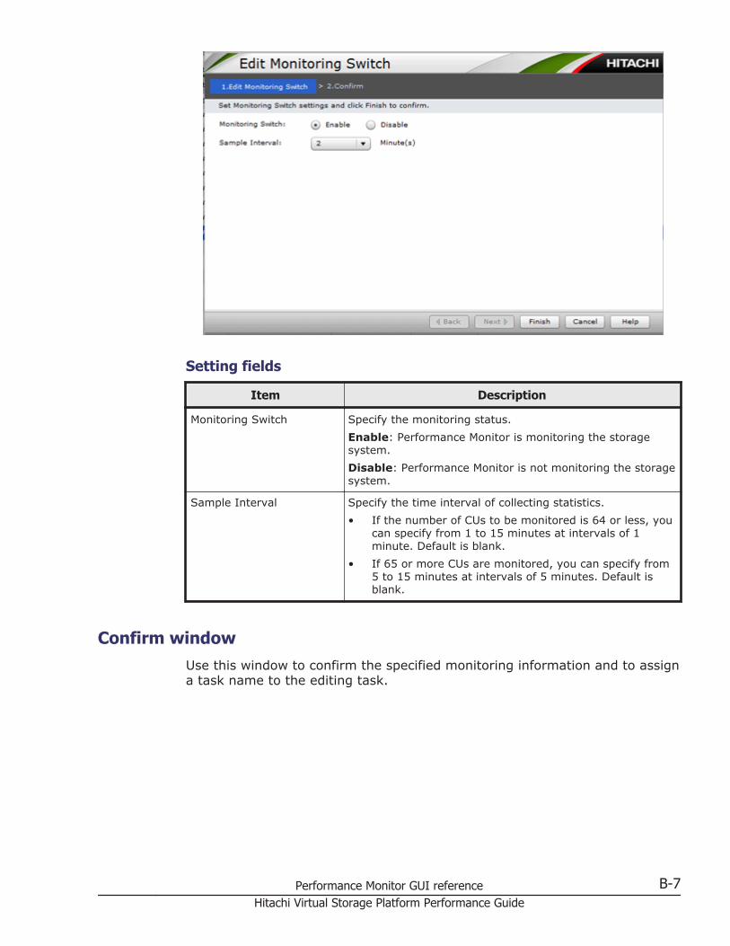
Setting fields
Item Description
Monitoring Switch Specify the monitoring status.Enable: Performance Monitor is monitoring the storagesystem.Disable: Performance Monitor is not monitoring the storagesystem.
Sample Interval Specify the time interval of collecting statistics.• If the number of CUs to be monitored is 64 or less, you
can specify from 1 to 15 minutes at intervals of 1minute. Default is blank.
• If 65 or more CUs are monitored, you can specify from5 to 15 minutes at intervals of 5 minutes. Default isblank.
Confirm windowUse this window to confirm the specified monitoring information and to assigna task name to the editing task.
Performance Monitor GUI reference B-7Hitachi Virtual Storage Platform Performance Guide
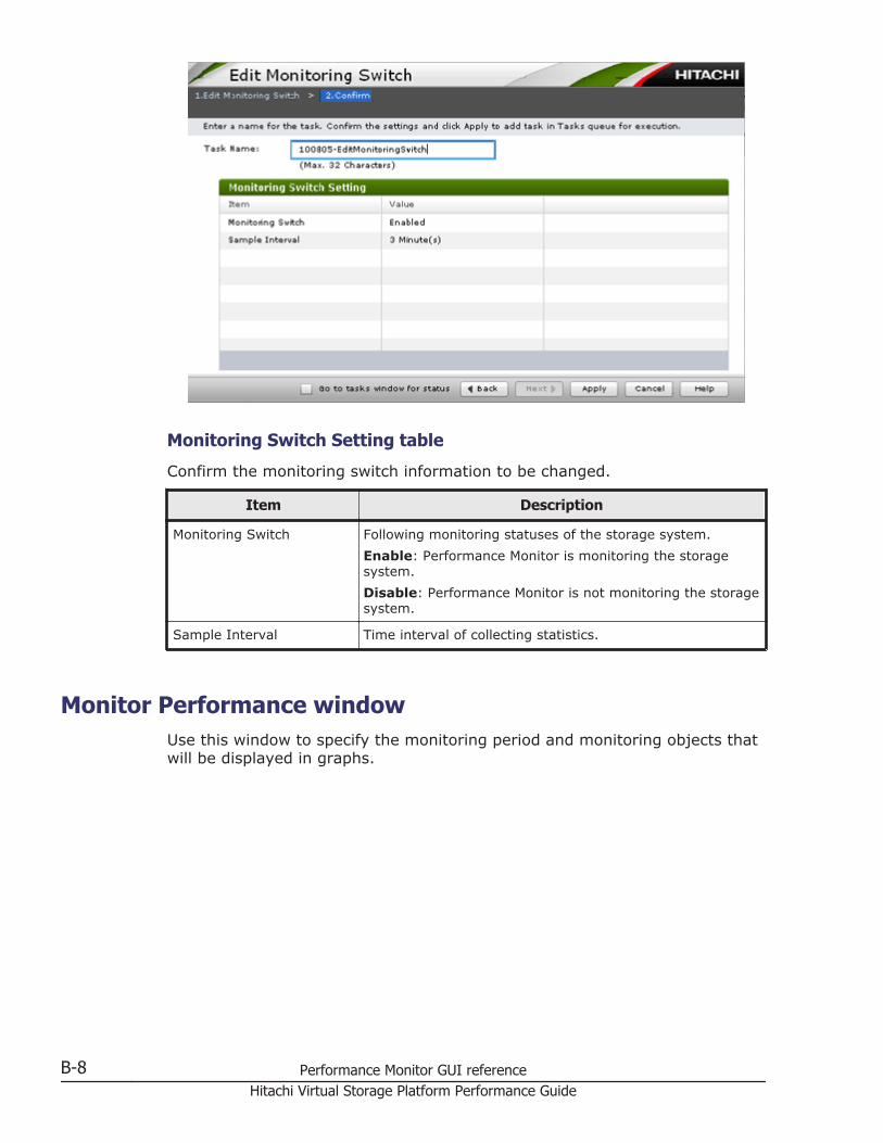
Monitoring Switch Setting table
Confirm the monitoring switch information to be changed.
Item Description
Monitoring Switch Following monitoring statuses of the storage system.Enable: Performance Monitor is monitoring the storagesystem.Disable: Performance Monitor is not monitoring the storagesystem.
Sample Interval Time interval of collecting statistics.
Monitor Performance windowUse this window to specify the monitoring period and monitoring objects thatwill be displayed in graphs.
B-8 Performance Monitor GUI referenceHitachi Virtual Storage Platform Performance Guide
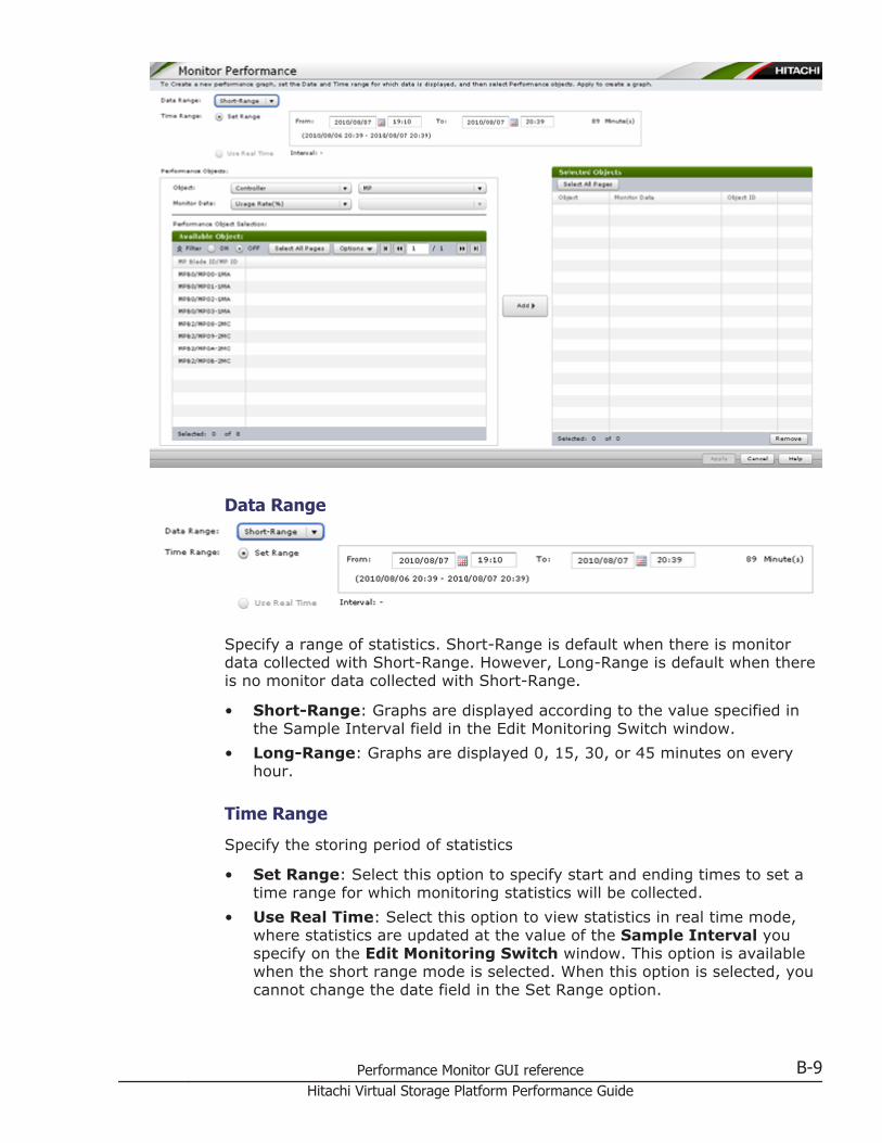
Data Range
Specify a range of statistics. Short-Range is default when there is monitordata collected with Short-Range. However, Long-Range is default when thereis no monitor data collected with Short-Range.
• Short-Range: Graphs are displayed according to the value specified inthe Sample Interval field in the Edit Monitoring Switch window.
• Long-Range: Graphs are displayed 0, 15, 30, or 45 minutes on everyhour.
Time Range
Specify the storing period of statistics
• Set Range: Select this option to specify start and ending times to set atime range for which monitoring statistics will be collected.
• Use Real Time: Select this option to view statistics in real time mode,where statistics are updated at the value of the Sample Interval youspecify on the Edit Monitoring Switch window. This option is availablewhen the short range mode is selected. When this option is selected, youcannot change the date field in the Set Range option.
Performance Monitor GUI reference B-9Hitachi Virtual Storage Platform Performance Guide
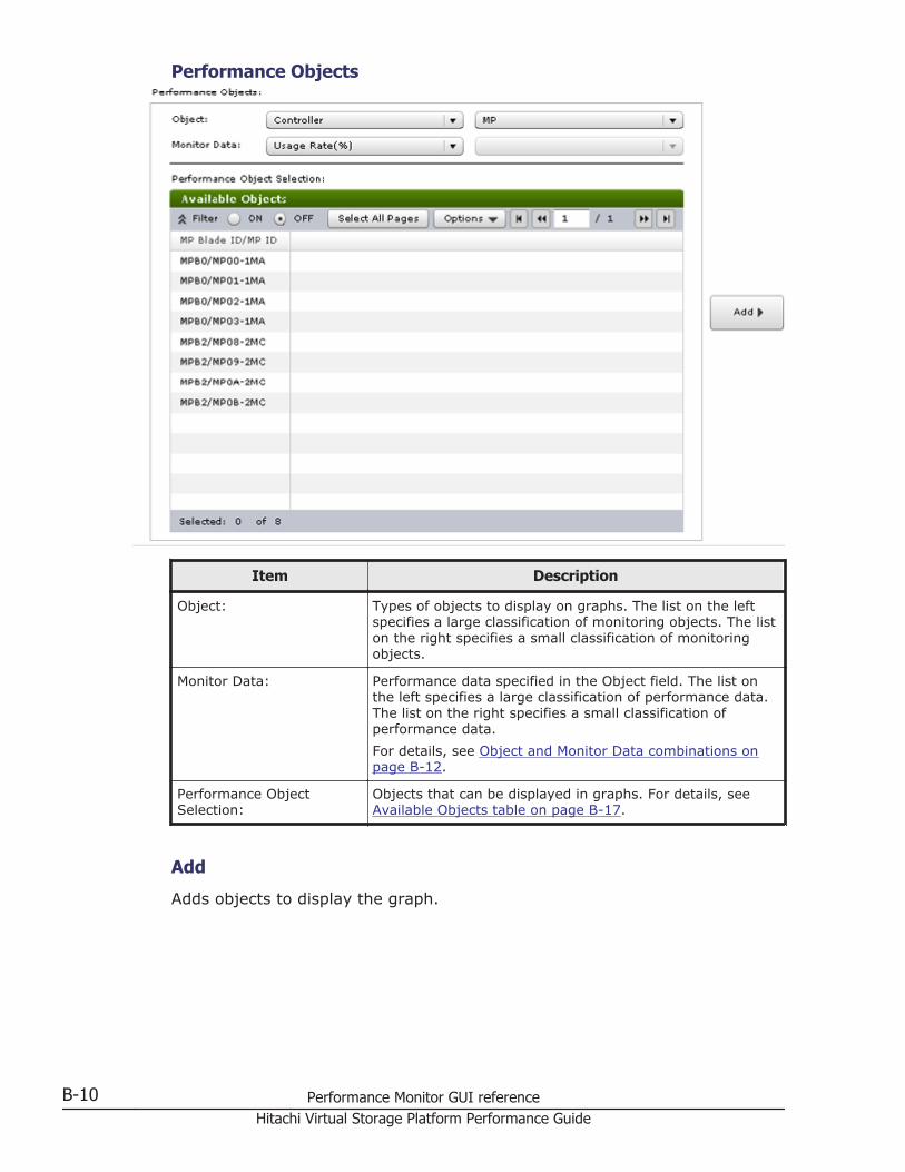
Performance Objects
Item Description
Object: Types of objects to display on graphs. The list on the leftspecifies a large classification of monitoring objects. The liston the right specifies a small classification of monitoringobjects.
Monitor Data: Performance data specified in the Object field. The list onthe left specifies a large classification of performance data.The list on the right specifies a small classification ofperformance data.For details, see Object and Monitor Data combinations onpage B-12.
Performance ObjectSelection:
Objects that can be displayed in graphs. For details, seeAvailable Objects table on page B-17.
Add
Adds objects to display the graph.
B-10 Performance Monitor GUI referenceHitachi Virtual Storage Platform Performance Guide
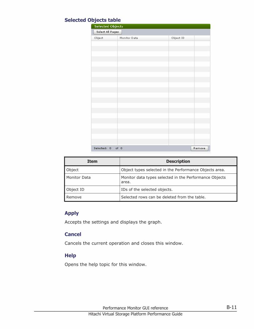
Selected Objects table
Item Description
Object Object types selected in the Performance Objects area.
Monitor Data Monitor data types selected in the Performance Objectsarea.
Object ID IDs of the selected objects.
Remove Selected rows can be deleted from the table.
Apply
Accepts the settings and displays the graph.
Cancel
Cancels the current operation and closes this window.
Help
Opens the help topic for this window.
Performance Monitor GUI reference B-11Hitachi Virtual Storage Platform Performance Guide
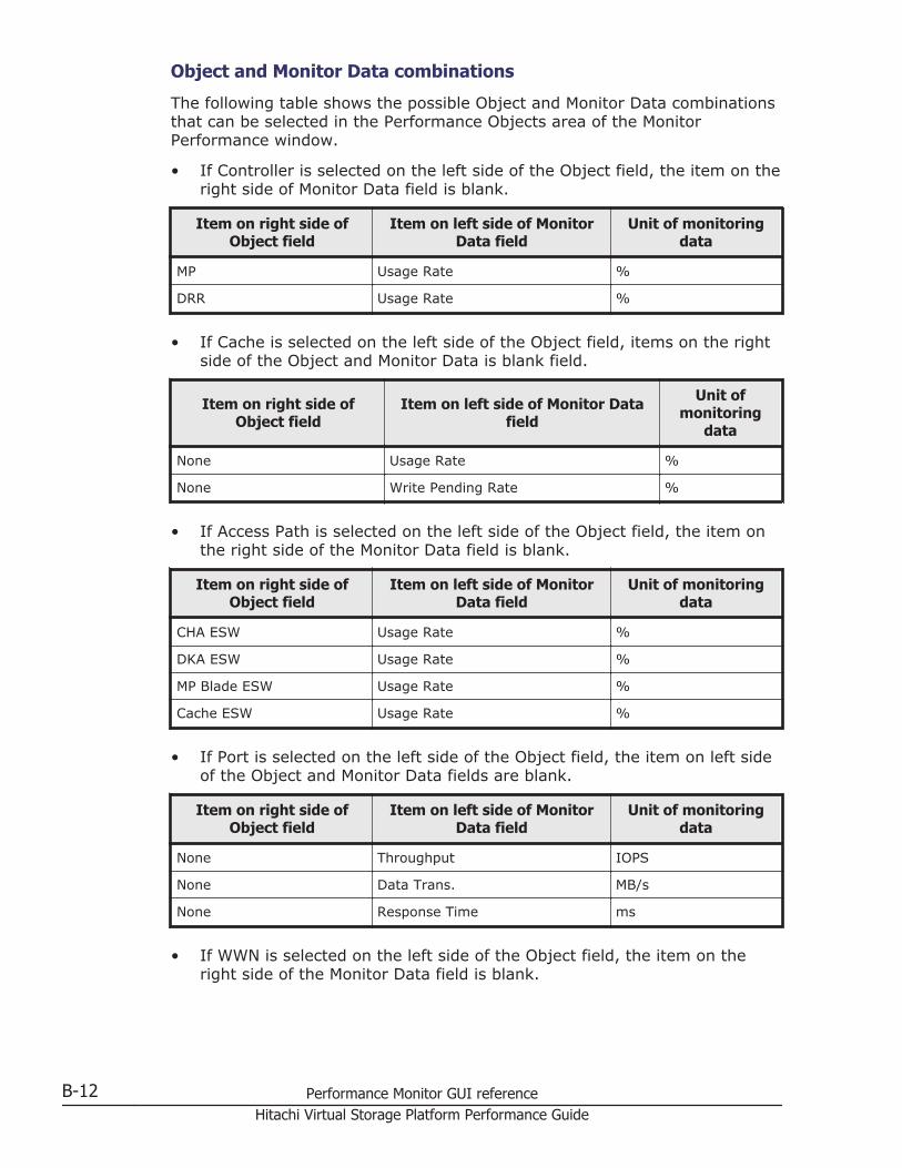
Object and Monitor Data combinations
The following table shows the possible Object and Monitor Data combinationsthat can be selected in the Performance Objects area of the MonitorPerformance window.
• If Controller is selected on the left side of the Object field, the item on theright side of Monitor Data field is blank.
Item on right side ofObject field
Item on left side of MonitorData field
Unit of monitoringdata
MP Usage Rate %
DRR Usage Rate %
• If Cache is selected on the left side of the Object field, items on the rightside of the Object and Monitor Data is blank field.
Item on right side ofObject field
Item on left side of Monitor Datafield
Unit ofmonitoring
data
None Usage Rate %
None Write Pending Rate %
• If Access Path is selected on the left side of the Object field, the item onthe right side of the Monitor Data field is blank.
Item on right side ofObject field
Item on left side of MonitorData field
Unit of monitoringdata
CHA ESW Usage Rate %
DKA ESW Usage Rate %
MP Blade ESW Usage Rate %
Cache ESW Usage Rate %
• If Port is selected on the left side of the Object field, the item on left sideof the Object and Monitor Data fields are blank.
Item on right side ofObject field
Item on left side of MonitorData field
Unit of monitoringdata
None Throughput IOPS
None Data Trans. MB/s
None Response Time ms
• If WWN is selected on the left side of the Object field, the item on theright side of the Monitor Data field is blank.
B-12 Performance Monitor GUI referenceHitachi Virtual Storage Platform Performance Guide
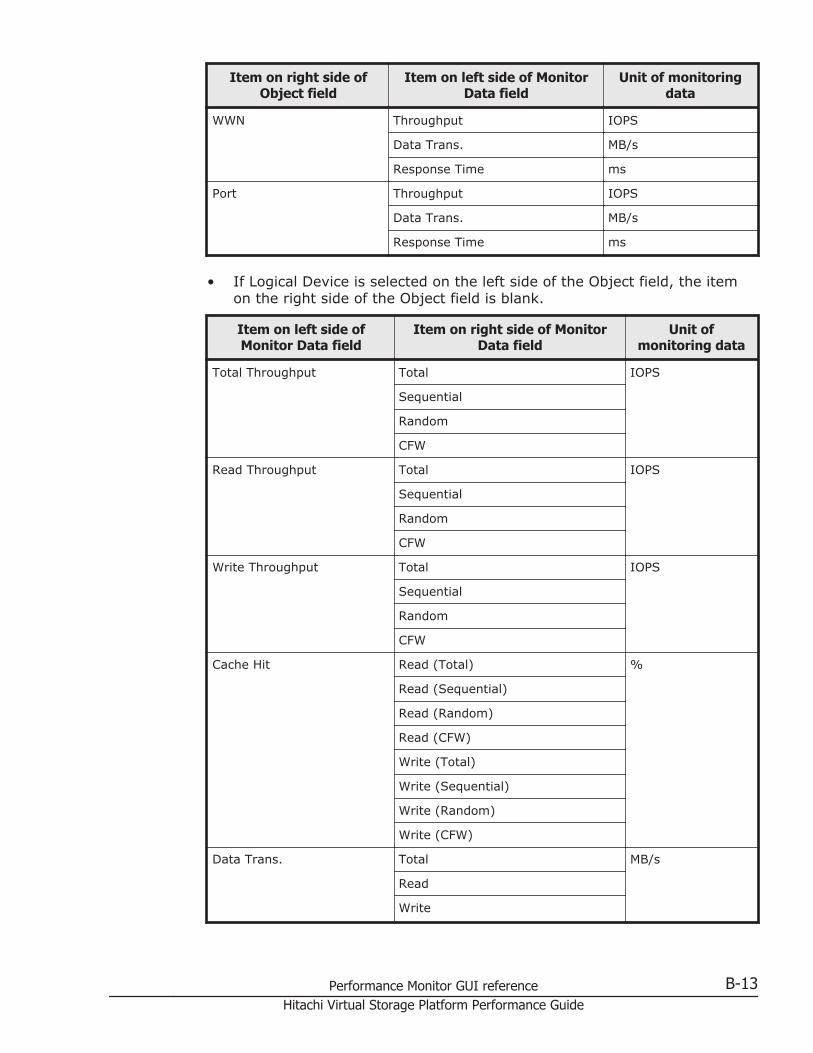
Item on right side ofObject field
Item on left side of MonitorData field
Unit of monitoringdata
WWN Throughput IOPS
Data Trans. MB/s
Response Time ms
Port Throughput IOPS
Data Trans. MB/s
Response Time ms
• If Logical Device is selected on the left side of the Object field, the itemon the right side of the Object field is blank.
Item on left side ofMonitor Data field
Item on right side of MonitorData field
Unit ofmonitoring data
Total Throughput Total IOPS
Sequential
Random
CFW
Read Throughput Total IOPS
Sequential
Random
CFW
Write Throughput Total IOPS
Sequential
Random
CFW
Cache Hit Read (Total) %
Read (Sequential)
Read (Random)
Read (CFW)
Write (Total)
Write (Sequential)
Write (Random)
Write (CFW)
Data Trans. Total MB/s
Read
Write
Performance Monitor GUI reference B-13Hitachi Virtual Storage Platform Performance Guide
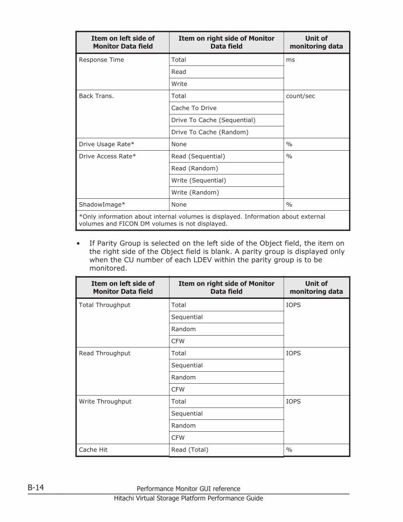
Item on left side ofMonitor Data field
Item on right side of MonitorData field
Unit ofmonitoring data
Response Time Total ms
Read
Write
Back Trans. Total count/sec
Cache To Drive
Drive To Cache (Sequential)
Drive To Cache (Random)
Drive Usage Rate* None %
Drive Access Rate* Read (Sequential) %
Read (Random)
Write (Sequential)
Write (Random)
ShadowImage* None %
*Only information about internal volumes is displayed. Information about externalvolumes and FICON DM volumes is not displayed.
• If Parity Group is selected on the left side of the Object field, the item onthe right side of the Object field is blank. A parity group is displayed onlywhen the CU number of each LDEV within the parity group is to bemonitored.
Item on left side ofMonitor Data field
Item on right side of MonitorData field
Unit ofmonitoring data
Total Throughput Total IOPS
Sequential
Random
CFW
Read Throughput Total IOPS
Sequential
Random
CFW
Write Throughput Total IOPS
Sequential
Random
CFW
Cache Hit Read (Total) %
B-14 Performance Monitor GUI referenceHitachi Virtual Storage Platform Performance Guide
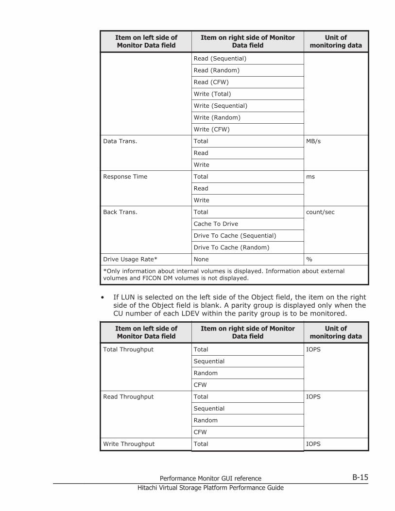
Item on left side ofMonitor Data field
Item on right side of MonitorData field
Unit ofmonitoring data
Read (Sequential)
Read (Random)
Read (CFW)
Write (Total)
Write (Sequential)
Write (Random)
Write (CFW)
Data Trans. Total MB/s
Read
Write
Response Time Total ms
Read
Write
Back Trans. Total count/sec
Cache To Drive
Drive To Cache (Sequential)
Drive To Cache (Random)
Drive Usage Rate* None %
*Only information about internal volumes is displayed. Information about externalvolumes and FICON DM volumes is not displayed.
• If LUN is selected on the left side of the Object field, the item on the rightside of the Object field is blank. A parity group is displayed only when theCU number of each LDEV within the parity group is to be monitored.
Item on left side ofMonitor Data field
Item on right side of MonitorData field
Unit ofmonitoring data
Total Throughput Total IOPS
Sequential
Random
CFW
Read Throughput Total IOPS
Sequential
Random
CFW
Write Throughput Total IOPS
Performance Monitor GUI reference B-15Hitachi Virtual Storage Platform Performance Guide
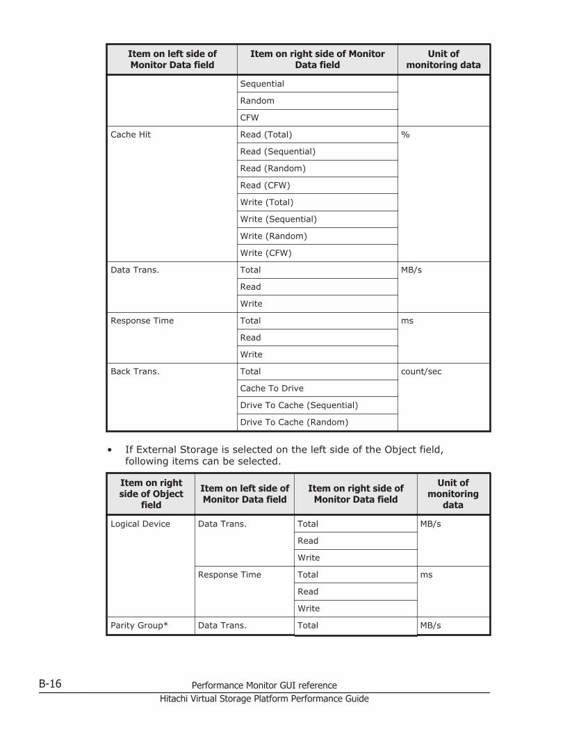
Item on left side ofMonitor Data field
Item on right side of MonitorData field
Unit ofmonitoring data
Sequential
Random
CFW
Cache Hit Read (Total) %
Read (Sequential)
Read (Random)
Read (CFW)
Write (Total)
Write (Sequential)
Write (Random)
Write (CFW)
Data Trans. Total MB/s
Read
Write
Response Time Total ms
Read
Write
Back Trans. Total count/sec
Cache To Drive
Drive To Cache (Sequential)
Drive To Cache (Random)
• If External Storage is selected on the left side of the Object field,following items can be selected.
Item on rightside of Object
field
Item on left side ofMonitor Data field
Item on right side ofMonitor Data field
Unit ofmonitoring
data
Logical Device Data Trans. Total MB/s
Read
Write
Response Time Total ms
Read
Write
Parity Group* Data Trans. Total MB/s
B-16 Performance Monitor GUI referenceHitachi Virtual Storage Platform Performance Guide
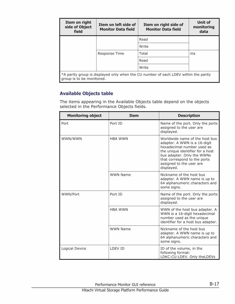
Item on rightside of Object
field
Item on left side ofMonitor Data field
Item on right side ofMonitor Data field
Unit ofmonitoring
data
Read
Write
Response Time Total ms
Read
Write
*A parity group is displayed only when the CU number of each LDEV within the paritygroup is to be monitored.
Available Objects table
The items appearing in the Available Objects table depend on the objectsselected in the Performance Objects fields.
Monitoring object Item Description
Port Port ID Name of the port. Only the portsassigned to the user aredisplayed.
WWN/WWN HBA WWN Worldwide name of the host busadapter. A WWN is a 16-digithexadecimal number used asthe unique identifier for a hostbus adapter. Only the WWNsthat correspond to the portsassigned to the user aredisplayed.
WWN Name Nickname of the host busadapter. A WWN name is up to64 alphanumeric characters andsome signs.
WWN/Port Port ID Name of the port. Only the portsassigned to the user aredisplayed.
HBA WWN WWN of the host bus adapter. AWWN is a 16-digit hexadecimalnumber used as the uniqueidentifier for a host bus adapter.
WWN Name Nickname of the host busadapter. A WWN name is up to64 alphanumeric characters andsome signs.
Logical Device LDEV ID ID of the volume, in thefollowing format:LDKC:CU:LDEV. Only theLDEVs
Performance Monitor GUI reference B-17Hitachi Virtual Storage Platform Performance Guide
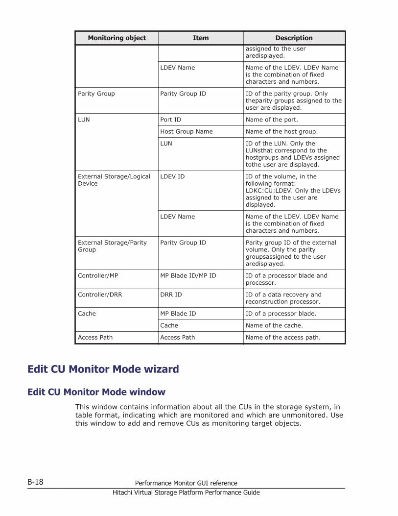
Monitoring object Item Description
assigned to the useraredisplayed.
LDEV Name Name of the LDEV. LDEV Nameis the combination of fixedcharacters and numbers.
Parity Group Parity Group ID ID of the parity group. Onlytheparity groups assigned to theuser are displayed.
LUN Port ID Name of the port.
Host Group Name Name of the host group.
LUN ID of the LUN. Only theLUNsthat correspond to thehostgroups and LDEVs assignedtothe user are displayed.
External Storage/LogicalDevice
LDEV ID ID of the volume, in thefollowing format:LDKC:CU:LDEV. Only the LDEVsassigned to the user aredisplayed.
LDEV Name Name of the LDEV. LDEV Nameis the combination of fixedcharacters and numbers.
External Storage/ParityGroup
Parity Group ID Parity group ID of the externalvolume. Only the paritygroupsassigned to the useraredisplayed.
Controller/MP MP Blade ID/MP ID ID of a processor blade andprocessor.
Controller/DRR DRR ID ID of a data recovery andreconstruction processor.
Cache MP Blade ID ID of a processor blade.
Cache Name of the cache.
Access Path Access Path Name of the access path.
Edit CU Monitor Mode wizard
Edit CU Monitor Mode windowThis window contains information about all the CUs in the storage system, intable format, indicating which are monitored and which are unmonitored. Usethis window to add and remove CUs as monitoring target objects.
B-18 Performance Monitor GUI referenceHitachi Virtual Storage Platform Performance Guide
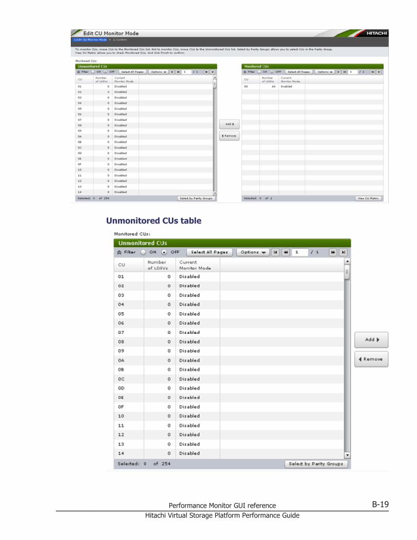
Unmonitored CUs table
Performance Monitor GUI reference B-19Hitachi Virtual Storage Platform Performance Guide
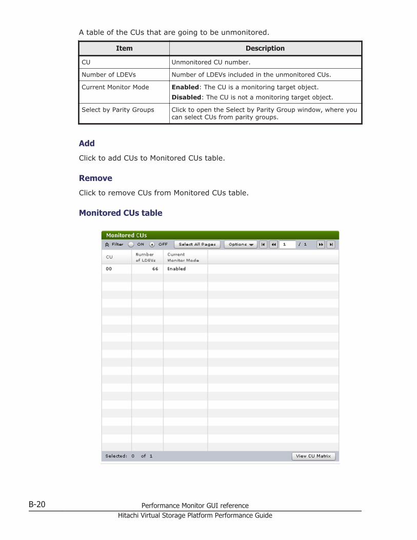
A table of the CUs that are going to be unmonitored.
Item Description
CU Unmonitored CU number.
Number of LDEVs Number of LDEVs included in the unmonitored CUs.
Current Monitor Mode Enabled: The CU is a monitoring target object.Disabled: The CU is not a monitoring target object.
Select by Parity Groups Click to open the Select by Parity Group window, where youcan select CUs from parity groups.
Add
Click to add CUs to Monitored CUs table.
Remove
Click to remove CUs from Monitored CUs table.
Monitored CUs table
B-20 Performance Monitor GUI referenceHitachi Virtual Storage Platform Performance Guide
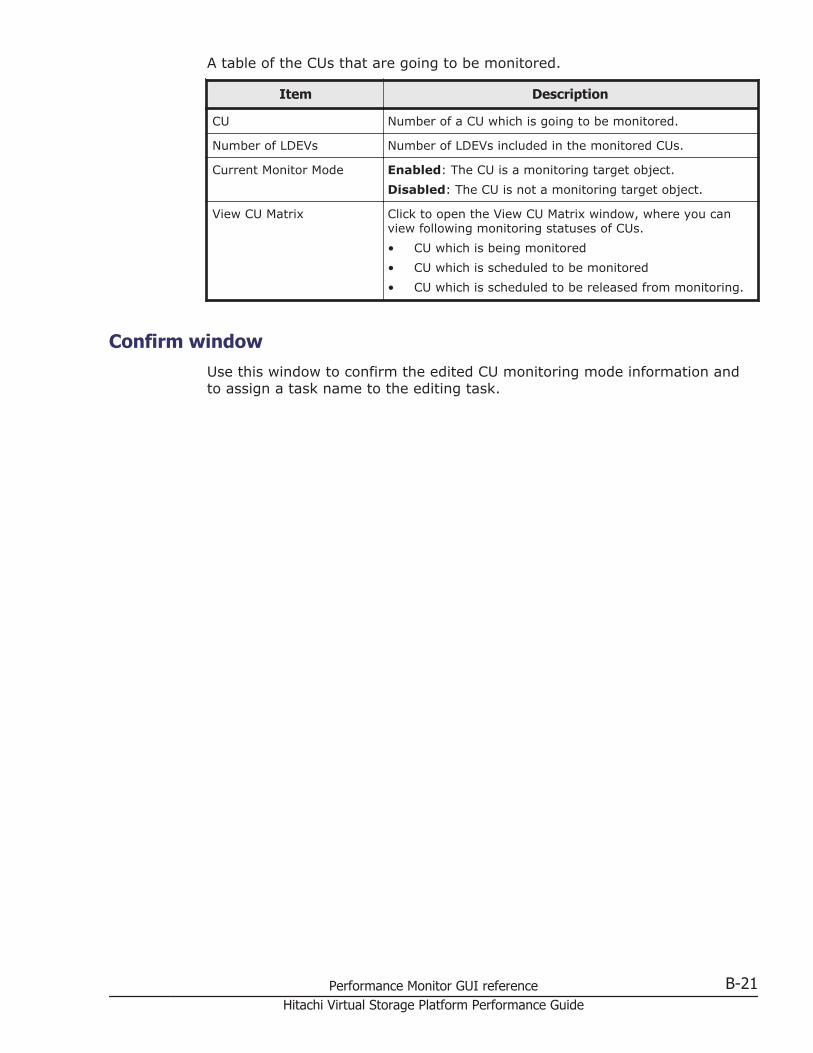
A table of the CUs that are going to be monitored.
Item Description
CU Number of a CU which is going to be monitored.
Number of LDEVs Number of LDEVs included in the monitored CUs.
Current Monitor Mode Enabled: The CU is a monitoring target object.Disabled: The CU is not a monitoring target object.
View CU Matrix Click to open the View CU Matrix window, where you canview following monitoring statuses of CUs.• CU which is being monitored• CU which is scheduled to be monitored• CU which is scheduled to be released from monitoring.
Confirm windowUse this window to confirm the edited CU monitoring mode information andto assign a task name to the editing task.
Performance Monitor GUI reference B-21Hitachi Virtual Storage Platform Performance Guide
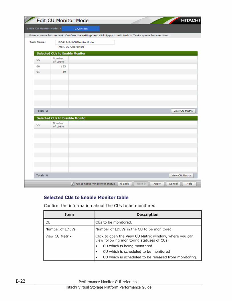
Selected CUs to Enable Monitor table
Confirm the information about the CUs to be monitored.
Item Description
CU CUs to be monitored.
Number of LDEVs Number of LDEVs in the CU to be monitored.
View CU Matrix Click to open the View CU Matrix window, where you canview following monitoring statuses of CUs.• CU which is being monitored• CU which is scheduled to be monitored• CU which is scheduled to be released from monitoring.
B-22 Performance Monitor GUI referenceHitachi Virtual Storage Platform Performance Guide
Selected CUs to Disable Monitor table
Information about the CUs not to be monitored.
Item Description
CU CUs not to be monitored.
Number of LDEVs Number of LDEVs in the CU not to be monitored.
View CU Matrix Click to open the View CU Matrix window, where you canview following monitoring statuses of CUs.• CU which is being monitored• CU which is scheduled to be monitored• CU which is scheduled to be released from monitoring.
View CU Matrix windowUse this window to view a matrix of the monitoring status of all the CUs inone LDKC. The cell markers indicate the monitoring status of the individualCUs.
Performance Monitor GUI reference B-23Hitachi Virtual Storage Platform Performance Guide
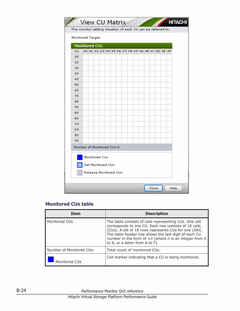
Monitored CUs table
Item Description
Monitored CUs The table consists of cells representing CUs. One cellcorresponds to one CU. Each row consists of 16 cells(CUs). A set of 16 rows represents CUs for one LDKC.The table header row shows the last digit of each CUnumber in the form of +n (where n is an integer from 0to 9, or a letter from A to F).
Number of Monitored CUs: Total count of monitored CUs.
Monitored CUsCell marker indicating that a CU is being monitored.
B-24 Performance Monitor GUI referenceHitachi Virtual Storage Platform Performance Guide
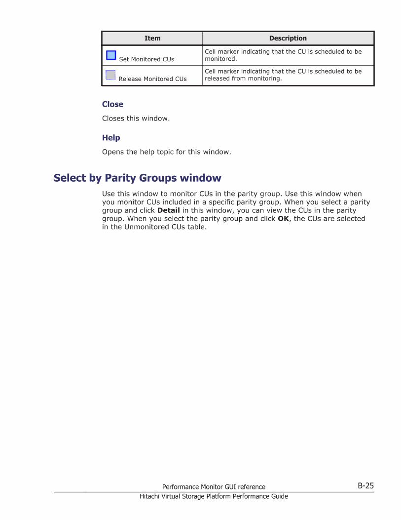
Item Description
Set Monitored CUsCell marker indicating that the CU is scheduled to bemonitored.
Release Monitored CUsCell marker indicating that the CU is scheduled to bereleased from monitoring.
Close
Closes this window.
Help
Opens the help topic for this window.
Select by Parity Groups windowUse this window to monitor CUs in the parity group. Use this window whenyou monitor CUs included in a specific parity group. When you select a paritygroup and click Detail in this window, you can view the CUs in the paritygroup. When you select the parity group and click OK, the CUs are selectedin the Unmonitored CUs table.
Performance Monitor GUI reference B-25Hitachi Virtual Storage Platform Performance Guide
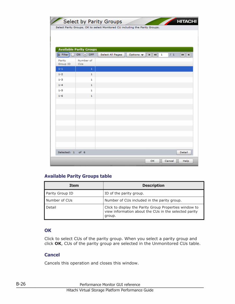
Available Parity Groups table
Item Description
Parity Group ID ID of the parity group.
Number of CUs Number of CUs included in the parity group.
Detail Click to display the Parity Group Properties window toview information about the CUs in the selected paritygroup.
OK
Click to select CUs of the parity group. When you select a parity group andclick OK, CUs of the parity group are selected in the Unmonitored CUs table.
Cancel
Cancels this operation and closes this window.
B-26 Performance Monitor GUI referenceHitachi Virtual Storage Platform Performance Guide
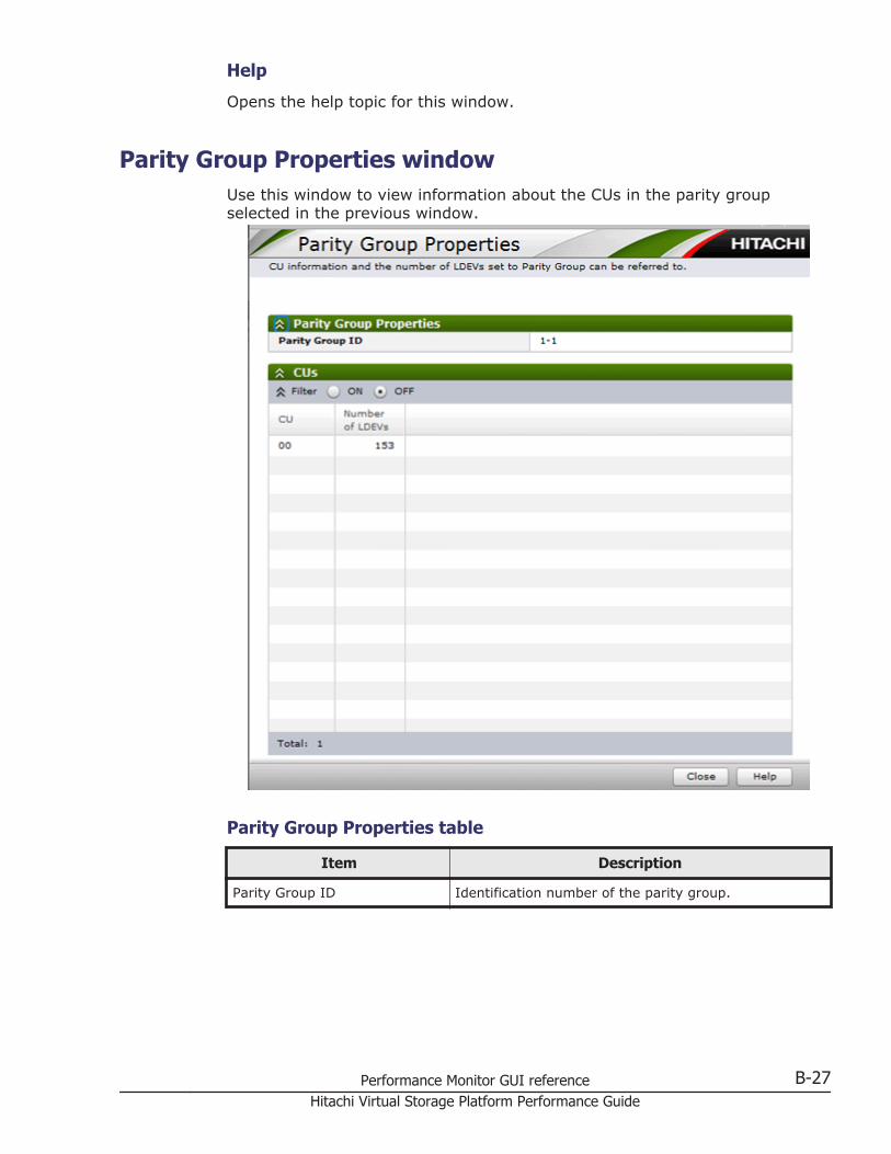
Help
Opens the help topic for this window.
Parity Group Properties windowUse this window to view information about the CUs in the parity groupselected in the previous window.
Parity Group Properties table
Item Description
Parity Group ID Identification number of the parity group.
Performance Monitor GUI reference B-27Hitachi Virtual Storage Platform Performance Guide
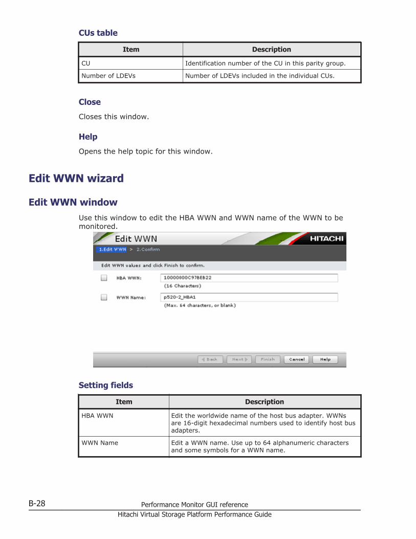
CUs table
Item Description
CU Identification number of the CU in this parity group.
Number of LDEVs Number of LDEVs included in the individual CUs.
Close
Closes this window.
Help
Opens the help topic for this window.
Edit WWN wizard
Edit WWN windowUse this window to edit the HBA WWN and WWN name of the WWN to bemonitored.
Setting fields
Item Description
HBA WWN Edit the worldwide name of the host bus adapter. WWNsare 16-digit hexadecimal numbers used to identify host busadapters.
WWN Name Edit a WWN name. Use up to 64 alphanumeric charactersand some symbols for a WWN name.
B-28 Performance Monitor GUI referenceHitachi Virtual Storage Platform Performance Guide
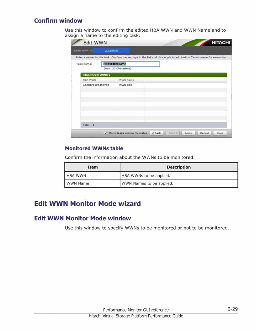
Confirm windowUse this window to confirm the edited HBA WWN and WWN Name and toassign a name to the editing task.
Monitored WWNs table
Confirm the information about the WWNs to be monitored.
Item Description
HBA WWN HBA WWNs to be applied.
WWN Name WWN Names to be applied.
Edit WWN Monitor Mode wizard
Edit WWN Monitor Mode windowUse this window to specify WWNs to be monitored or not to be monitored.
Performance Monitor GUI reference B-29Hitachi Virtual Storage Platform Performance Guide
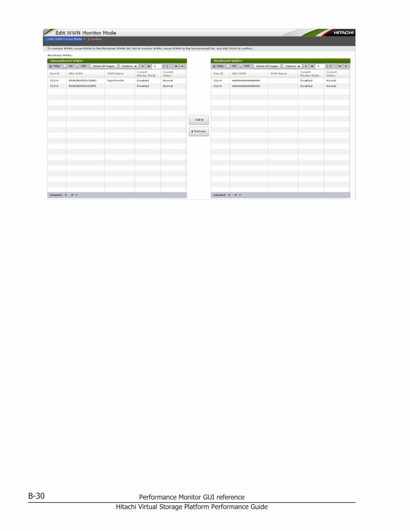
B-30 Performance Monitor GUI referenceHitachi Virtual Storage Platform Performance Guide
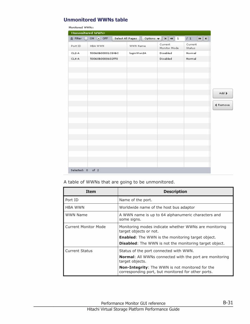
Unmonitored WWNs table
A table of WWNs that are going to be unmonitored.
Item Description
Port ID Name of the port.
HBA WWN Worldwide name of the host bus adaptor
WWN Name A WWN name is up to 64 alphanumeric characters andsome signs.
Current Monitor Mode Monitoring modes indicate whether WWNs are monitoringtarget objects or not.Enabled: The WWN is the monitoring target object.Disabled: The WWN is not the monitoring target object.
Current Status Status of the port connected with WWN.Normal: All WWNs connected with the port are monitoringtarget objects.Non-Integrity: The WWN is not monitored for thecorresponding port, but monitored for other ports.
Performance Monitor GUI reference B-31Hitachi Virtual Storage Platform Performance Guide
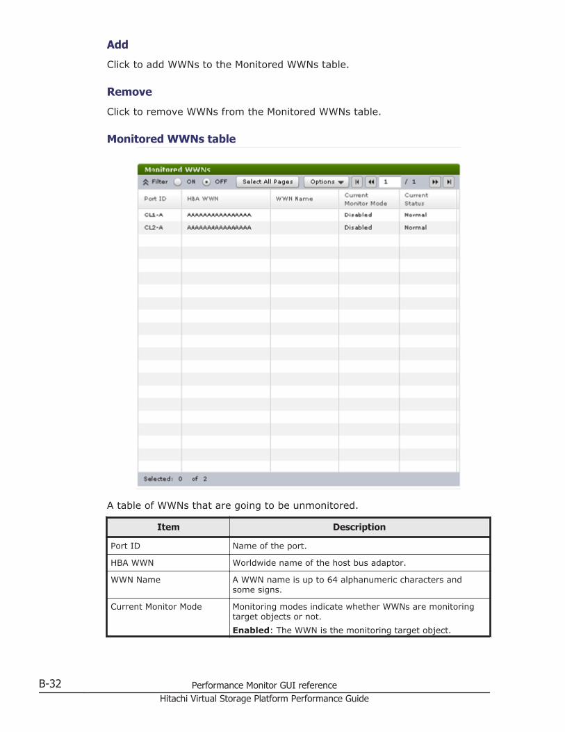
Add
Click to add WWNs to the Monitored WWNs table.
Remove
Click to remove WWNs from the Monitored WWNs table.
Monitored WWNs table
A table of WWNs that are going to be unmonitored.
Item Description
Port ID Name of the port.
HBA WWN Worldwide name of the host bus adaptor.
WWN Name A WWN name is up to 64 alphanumeric characters andsome signs.
Current Monitor Mode Monitoring modes indicate whether WWNs are monitoringtarget objects or not.Enabled: The WWN is the monitoring target object.
B-32 Performance Monitor GUI referenceHitachi Virtual Storage Platform Performance Guide
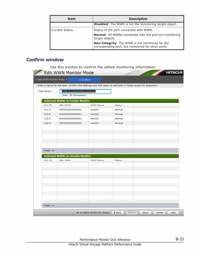
Item Description
Disabled: The WWN is not the monitoring target object.
Current Status Status of the port connected with WWN.Normal: All WWNs connected with the port are monitoringtarget objects.Non-Integrity: The WWN is not monitored for thecorresponding port, but monitored for other ports.
Confirm windowUse this window to confirm the edited monitoring information.
Performance Monitor GUI reference B-33Hitachi Virtual Storage Platform Performance Guide
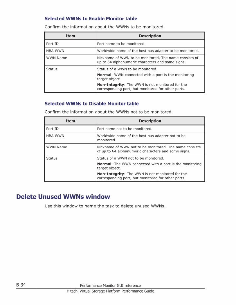
Selected WWNs to Enable Monitor table
Confirm the information about the WWNs to be monitored.
Item Description
Port ID Port name to be monitored.
HBA WWN Worldwide name of the host bus adapter to be monitored.
WWN Name Nickname of WWN to be monitored. The name consists ofup to 64 alphanumeric characters and some signs.
Status Status of a WWN to be monitored.Normal: WWN connected with a port is the monitoringtarget object.Non-Integrity: The WWN is not monitored for thecorresponding port, but monitored for other ports.
Selected WWNs to Disable Monitor table
Confirm the information about the WWNs not to be monitored.
Item Description
Port ID Port name not to be monitored.
HBA WWN Worldwide name of the host bus adapter not to bemonitored.
WWN Name Nickname of WWN not to be monitored. The name consistsof up to 64 alphanumeric characters and some signs.
Status Status of a WWN not to be monitored.Normal: The WWN connected with a port is the monitoringtarget object.Non-Integrity: The WWN is not monitored for thecorresponding port, but monitored for other ports.
Delete Unused WWNs windowUse this window to name the task to delete unused WWNs.
B-34 Performance Monitor GUI referenceHitachi Virtual Storage Platform Performance Guide
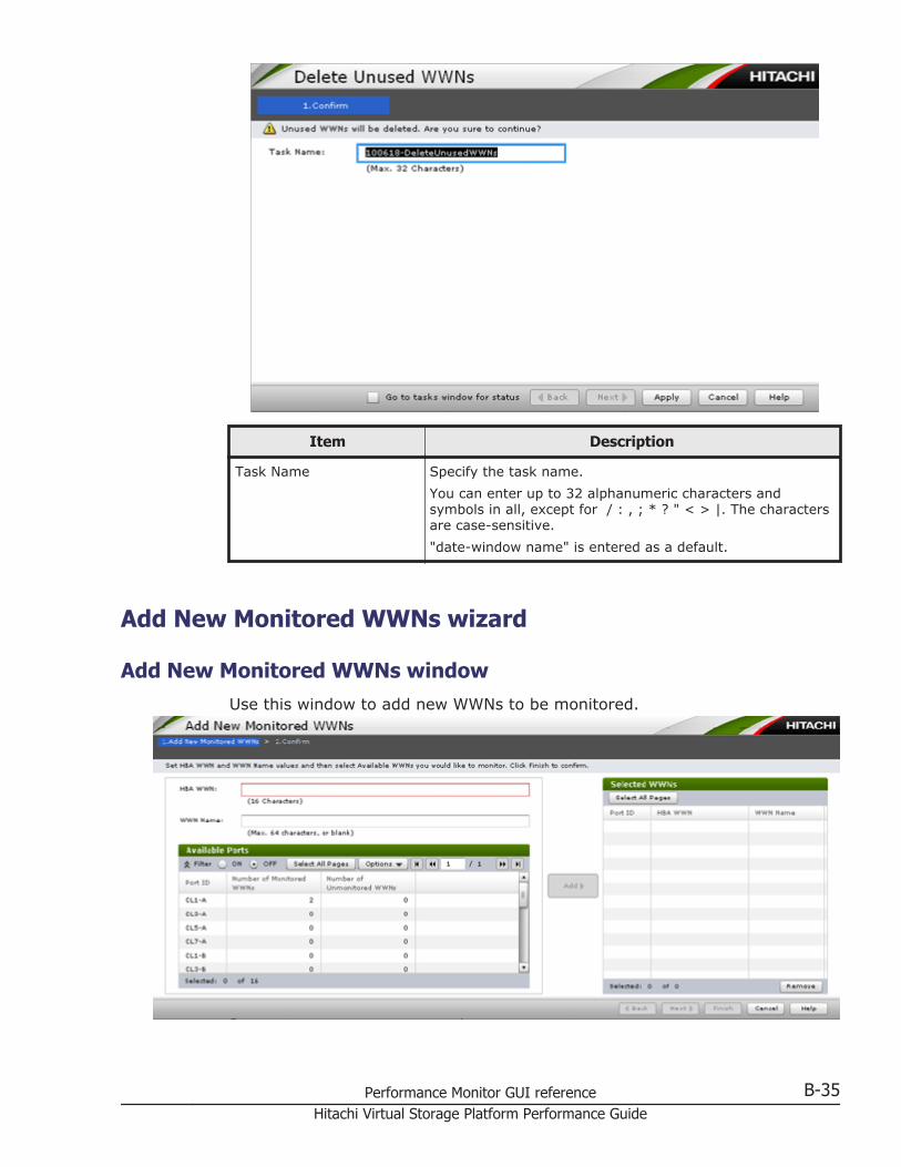
Item Description
Task Name Specify the task name.You can enter up to 32 alphanumeric characters andsymbols in all, except for / : , ; * ? " < > |. The charactersare case-sensitive."date-window name" is entered as a default.
Add New Monitored WWNs wizard
Add New Monitored WWNs windowUse this window to add new WWNs to be monitored.
Performance Monitor GUI reference B-35Hitachi Virtual Storage Platform Performance Guide
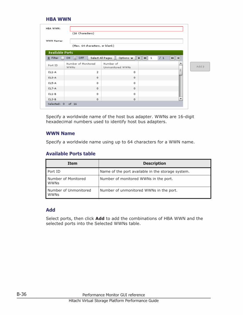
HBA WWN
Specify a worldwide name of the host bus adapter. WWNs are 16-digithexadecimal numbers used to identify host bus adapters.
WWN Name
Specify a worldwide name using up to 64 characters for a WWN name.
Available Ports table
Item Description
Port ID Name of the port available in the storage system.
Number of MonitoredWWNs
Number of monitored WWNs in the port.
Number of UnmonitoredWWNs
Number of unmonitored WWNs in the port.
Add
Select ports, then click Add to add the combinations of HBA WWN and theselected ports into the Selected WWNs table.
B-36 Performance Monitor GUI referenceHitachi Virtual Storage Platform Performance Guide
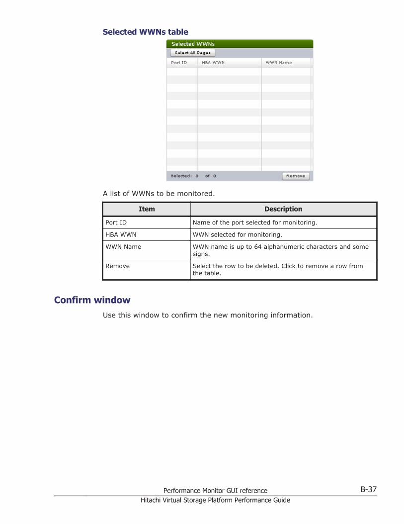
Selected WWNs table
A list of WWNs to be monitored.
Item Description
Port ID Name of the port selected for monitoring.
HBA WWN WWN selected for monitoring.
WWN Name WWN name is up to 64 alphanumeric characters and somesigns.
Remove Select the row to be deleted. Click to remove a row fromthe table.
Confirm windowUse this window to confirm the new monitoring information.
Performance Monitor GUI reference B-37Hitachi Virtual Storage Platform Performance Guide
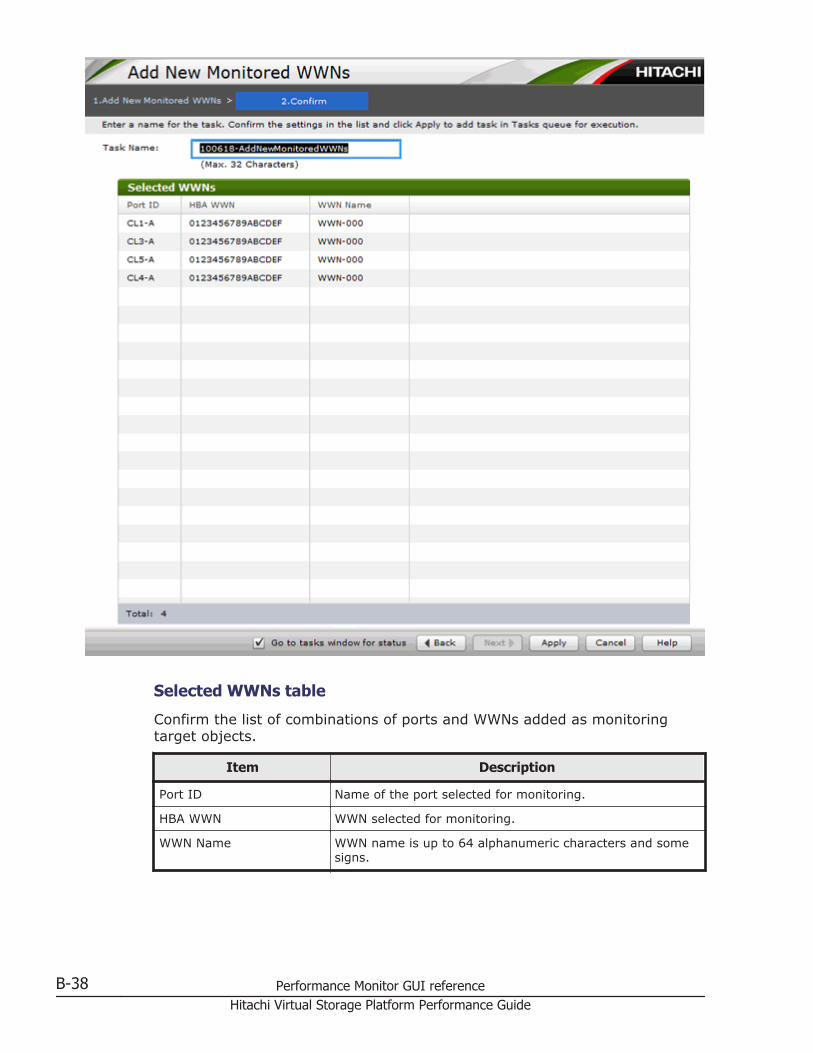
Selected WWNs table
Confirm the list of combinations of ports and WWNs added as monitoringtarget objects.
Item Description
Port ID Name of the port selected for monitoring.
HBA WWN WWN selected for monitoring.
WWN Name WWN name is up to 64 alphanumeric characters and somesigns.
B-38 Performance Monitor GUI referenceHitachi Virtual Storage Platform Performance Guide
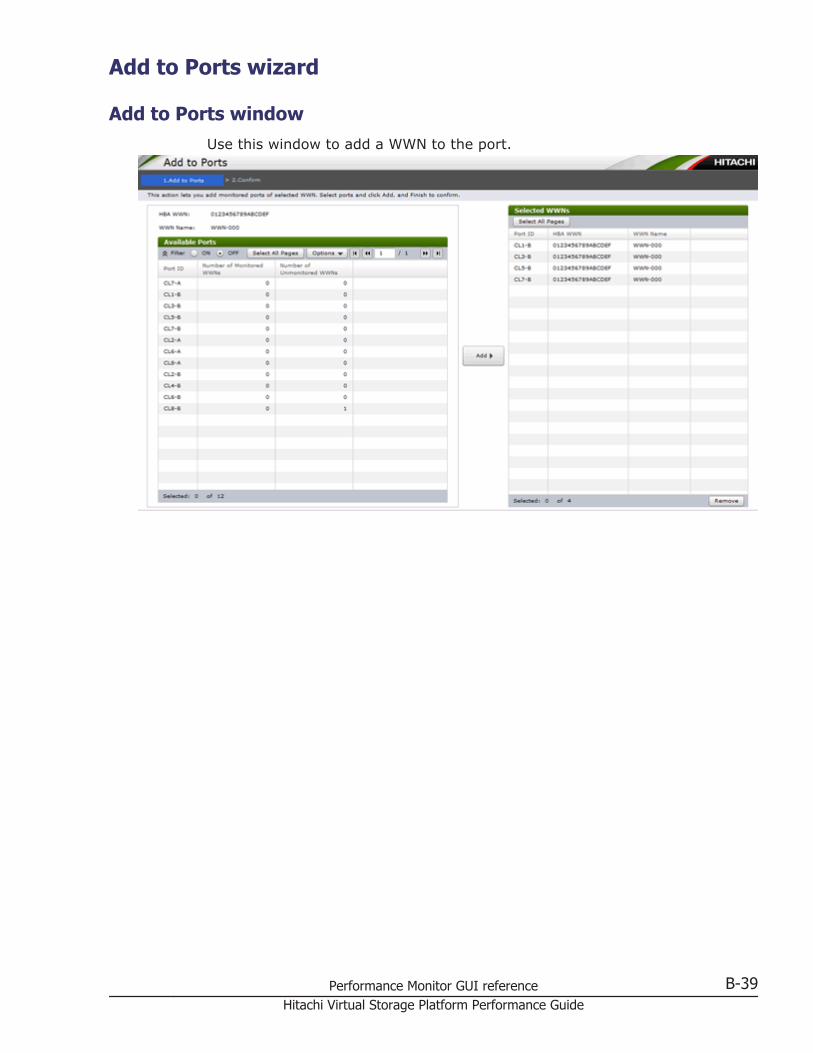
Add to Ports wizard
Add to Ports windowUse this window to add a WWN to the port.
Performance Monitor GUI reference B-39Hitachi Virtual Storage Platform Performance Guide
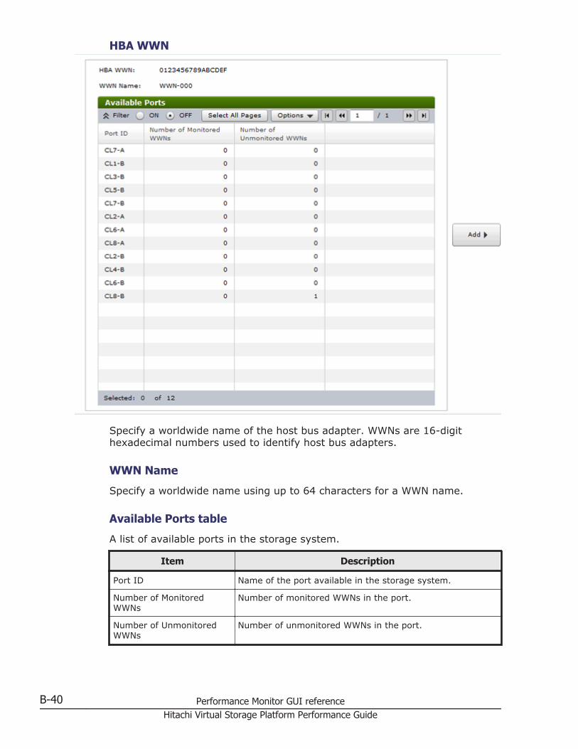
HBA WWN
Specify a worldwide name of the host bus adapter. WWNs are 16-digithexadecimal numbers used to identify host bus adapters.
WWN Name
Specify a worldwide name using up to 64 characters for a WWN name.
Available Ports table
A list of available ports in the storage system.
Item Description
Port ID Name of the port available in the storage system.
Number of MonitoredWWNs
Number of monitored WWNs in the port.
Number of UnmonitoredWWNs
Number of unmonitored WWNs in the port.
B-40 Performance Monitor GUI referenceHitachi Virtual Storage Platform Performance Guide
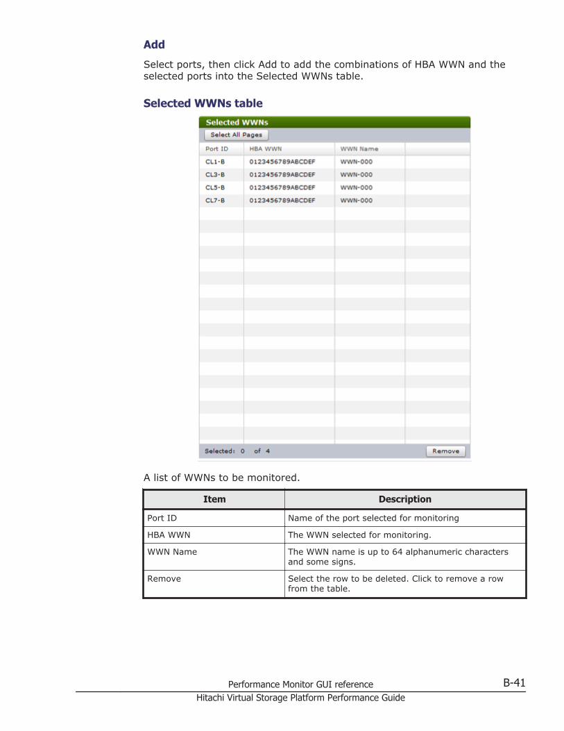
Add
Select ports, then click Add to add the combinations of HBA WWN and theselected ports into the Selected WWNs table.
Selected WWNs table
A list of WWNs to be monitored.
Item Description
Port ID Name of the port selected for monitoring
HBA WWN The WWN selected for monitoring.
WWN Name The WWN name is up to 64 alphanumeric charactersand some signs.
Remove Select the row to be deleted. Click to remove a rowfrom the table.
Performance Monitor GUI reference B-41Hitachi Virtual Storage Platform Performance Guide
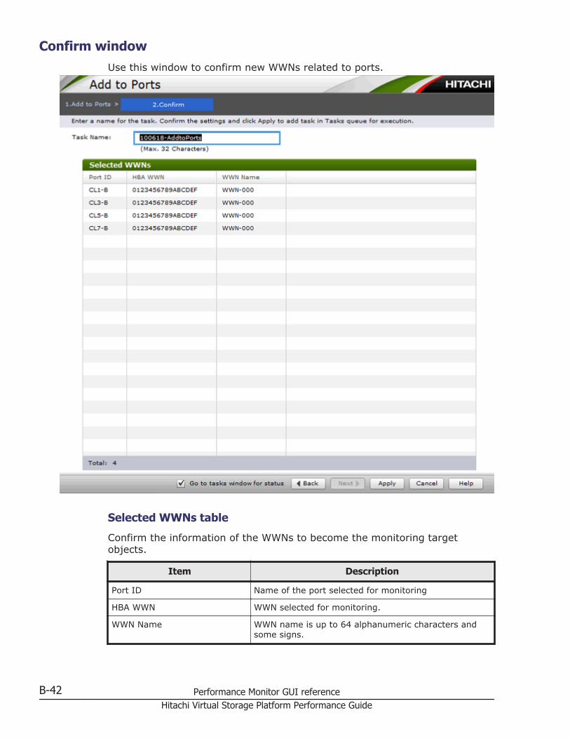
Confirm windowUse this window to confirm new WWNs related to ports.
Selected WWNs table
Confirm the information of the WWNs to become the monitoring targetobjects.
Item Description
Port ID Name of the port selected for monitoring
HBA WWN WWN selected for monitoring.
WWN Name WWN name is up to 64 alphanumeric characters andsome signs.
B-42 Performance Monitor GUI referenceHitachi Virtual Storage Platform Performance Guide
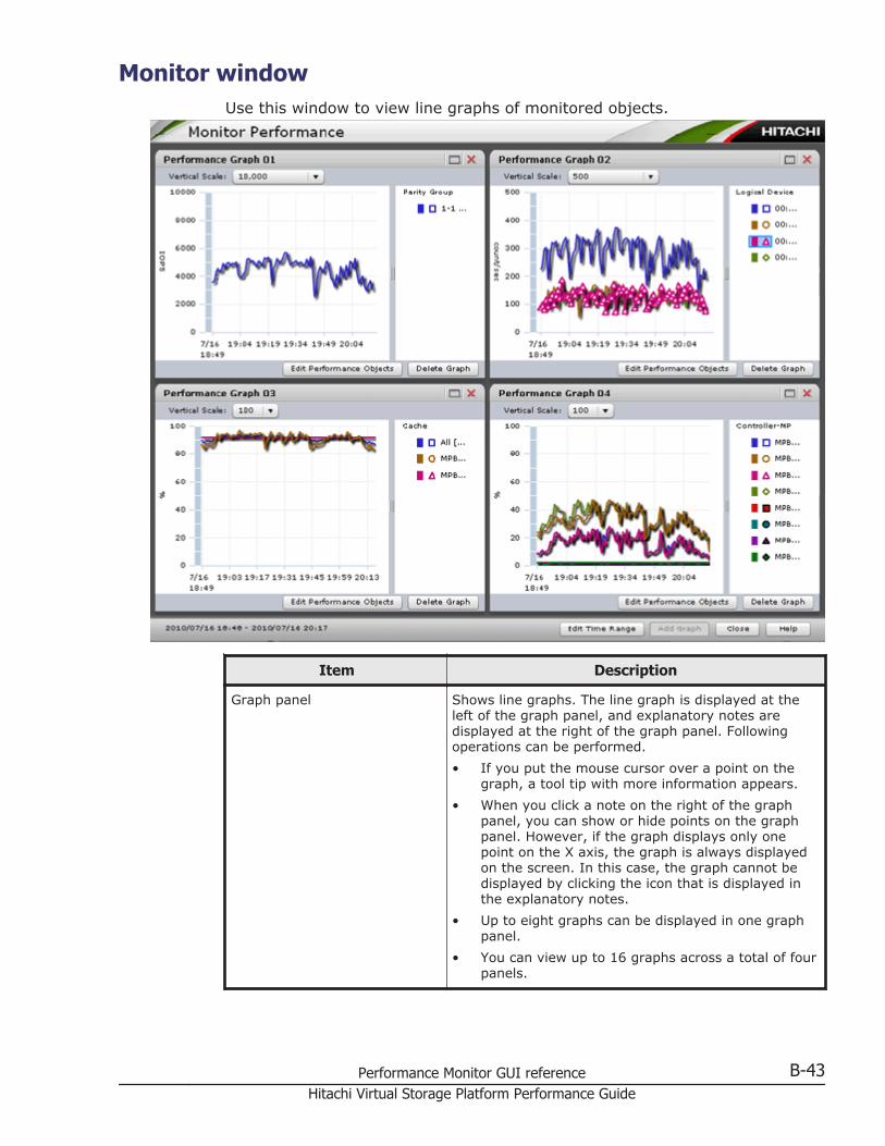
Monitor windowUse this window to view line graphs of monitored objects.
Item Description
Graph panel Shows line graphs. The line graph is displayed at theleft of the graph panel, and explanatory notes aredisplayed at the right of the graph panel. Followingoperations can be performed.• If you put the mouse cursor over a point on the
graph, a tool tip with more information appears.• When you click a note on the right of the graph
panel, you can show or hide points on the graphpanel. However, if the graph displays only onepoint on the X axis, the graph is always displayedon the screen. In this case, the graph cannot bedisplayed by clicking the icon that is displayed inthe explanatory notes.
• Up to eight graphs can be displayed in one graphpanel.
• You can view up to 16 graphs across a total of fourpanels.
Performance Monitor GUI reference B-43Hitachi Virtual Storage Platform Performance Guide
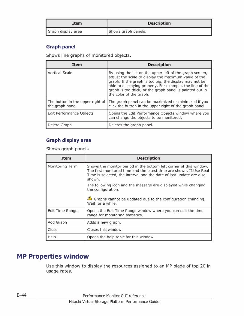
Item Description
Graph display area Shows graph panels.
Graph panel
Shows line graphs of monitored objects.
Item Description
Vertical Scale: By using the list on the upper left of the graph screen,adjust the scale to display the maximum value of thegraph. If the graph is too big, the display may not beable to displaying properly. For example, the line of thegraph is too thick, or the graph panel is painted out inthe color of the graph.
The button in the upper right ofthe graph panel
The graph panel can be maximized or minimized if youclick the button in the upper right of the graph panel.
Edit Performance Objects Opens the Edit Performance Objects window where youcan change the objects to be monitored.
Delete Graph Deletes the graph panel.
Graph display area
Shows graph panels.
Item Description
Monitoring Term Shows the monitor period in the bottom left corner of this window.The first monitored time and the latest time are shown. If Use RealTime is selected, the interval and the date of last update are alsoshown.The following icon and the message are displayed while changingthe configuration:
Graphs cannot be updated due to the configuration changing.Wait for a while.
Edit Time Range Opens the Edit Time Range window where you can edit the timerange for monitoring statistics.
Add Graph Adds a new graph.
Close Closes this window.
Help Opens the help topic for this window.
MP Properties windowUse this window to display the resources assigned to an MP blade of top 20 inusage rates.
B-44 Performance Monitor GUI referenceHitachi Virtual Storage Platform Performance Guide
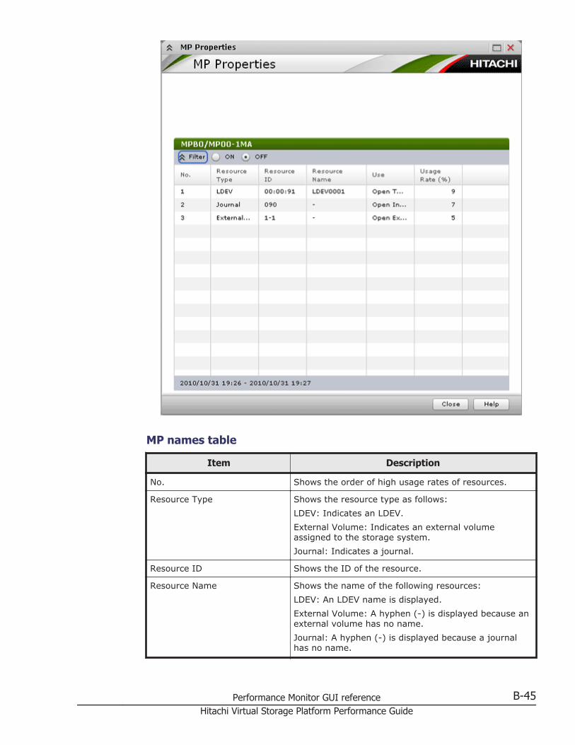
MP names table
Item Description
No. Shows the order of high usage rates of resources.
Resource Type Shows the resource type as follows:LDEV: Indicates an LDEV.External Volume: Indicates an external volumeassigned to the storage system.Journal: Indicates a journal.
Resource ID Shows the ID of the resource.
Resource Name Shows the name of the following resources:LDEV: An LDEV name is displayed.External Volume: A hyphen (-) is displayed because anexternal volume has no name.Journal: A hyphen (-) is displayed because a journalhas no name.
Performance Monitor GUI reference B-45Hitachi Virtual Storage Platform Performance Guide
Item Description
Use Shows a kernel type of a resource as follows:Open Target: Indicates that this resource is used onthe front end for the open system.Open External: Indicates that this resource is used bythe external storage system for the open system.Open Initiator: Indicates that this resource is used bythe initiator for the open system.Mainframe Target: Indicates that this resource is usedon the front end for the mainframe.Mainframe External: Indicates that this resource isused by the external storage system for themainframe.Back-end: Indicates that this resource is used on theback end.System: Indicates that this resource is used by themaintenance and other functions.
Usage Rate (%) Shows a usage rate of a resource.The rate (%) of a resource processed in the latestmonitoring period is displayed.
Close
Closes this window.
Help
Opens the help topic for this window.
Edit Time Range windowUse this window to select a date and time range for displaying monitoringdata in a performance graph.
B-46 Performance Monitor GUI referenceHitachi Virtual Storage Platform Performance Guide
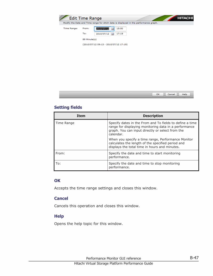
Setting fields
Item Description
Time Range Specify dates in the From and To fields to define a timerange for displaying monitoring data in a performancegraph. You can input directly or select from thecalendar.When you specify a time range, Performance Monitorcalculates the length of the specified period anddisplays the total time in hours and minutes.
From: Specify the date and time to start monitoringperformance.
To: Specify the date and time to stop monitoringperformance.
OK
Accepts the time range settings and closes this window.
Cancel
Cancels this operation and closes this window.
Help
Opens the help topic for this window.
Performance Monitor GUI reference B-47Hitachi Virtual Storage Platform Performance Guide
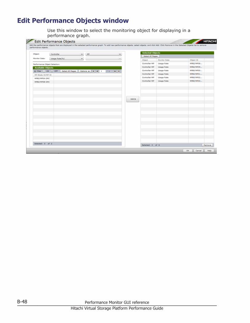
Edit Performance Objects windowUse this window to select the monitoring object for displaying in aperformance graph.
B-48 Performance Monitor GUI referenceHitachi Virtual Storage Platform Performance Guide
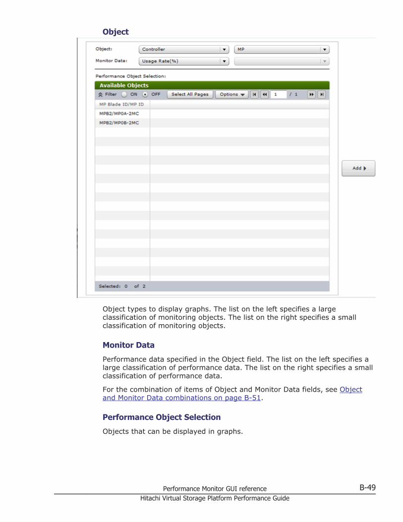
Object
Object types to display graphs. The list on the left specifies a largeclassification of monitoring objects. The list on the right specifies a smallclassification of monitoring objects.
Monitor Data
Performance data specified in the Object field. The list on the left specifies alarge classification of performance data. The list on the right specifies a smallclassification of performance data.
For the combination of items of Object and Monitor Data fields, see Objectand Monitor Data combinations on page B-51.
Performance Object Selection
Objects that can be displayed in graphs.
Performance Monitor GUI reference B-49Hitachi Virtual Storage Platform Performance Guide

Available Objects table
The columns depend on the object selected. For details, see Available Objectstable on page B-56.
Add
Adds objects to display the graph.
Selected Objects table
Objects to display the graph.
Item Description
Object Object to display the graph.
Monitor Data Type of monitoring data.
Object ID ID of the monitoring object.
Remove Remove the object in this table.
B-50 Performance Monitor GUI referenceHitachi Virtual Storage Platform Performance Guide
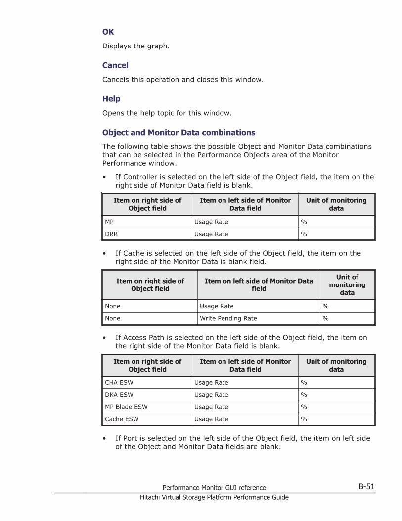
OK
Displays the graph.
Cancel
Cancels this operation and closes this window.
Help
Opens the help topic for this window.
Object and Monitor Data combinations
The following table shows the possible Object and Monitor Data combinationsthat can be selected in the Performance Objects area of the MonitorPerformance window.
• If Controller is selected on the left side of the Object field, the item on theright side of Monitor Data field is blank.
Item on right side ofObject field
Item on left side of MonitorData field
Unit of monitoringdata
MP Usage Rate %
DRR Usage Rate %
• If Cache is selected on the left side of the Object field, the item on theright side of the Monitor Data is blank field.
Item on right side ofObject field
Item on left side of Monitor Datafield
Unit ofmonitoring
data
None Usage Rate %
None Write Pending Rate %
• If Access Path is selected on the left side of the Object field, the item onthe right side of the Monitor Data field is blank.
Item on right side ofObject field
Item on left side of MonitorData field
Unit of monitoringdata
CHA ESW Usage Rate %
DKA ESW Usage Rate %
MP Blade ESW Usage Rate %
Cache ESW Usage Rate %
• If Port is selected on the left side of the Object field, the item on left sideof the Object and Monitor Data fields are blank.
Performance Monitor GUI reference B-51Hitachi Virtual Storage Platform Performance Guide
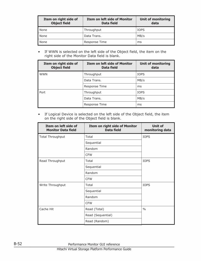
Item on right side ofObject field
Item on left side of MonitorData field
Unit of monitoringdata
None Throughput IOPS
None Data Trans. MB/s
None Response Time ms
• If WWN is selected on the left side of the Object field, the item on theright side of the Monitor Data field is blank.
Item on right side ofObject field
Item on left side of MonitorData field
Unit of monitoringdata
WWN Throughput IOPS
Data Trans. MB/s
Response Time ms
Port Throughput IOPS
Data Trans. MB/s
Response Time ms
• If Logical Device is selected on the left side of the Object field, the itemon the right side of the Object field is blank.
Item on left side ofMonitor Data field
Item on right side of MonitorData field
Unit ofmonitoring data
Total Throughput Total IOPS
Sequential
Random
CFW
Read Throughput Total IOPS
Sequential
Random
CFW
Write Throughput Total IOPS
Sequential
Random
CFW
Cache Hit Read (Total) %
Read (Sequential)
Read (Random)
B-52 Performance Monitor GUI referenceHitachi Virtual Storage Platform Performance Guide
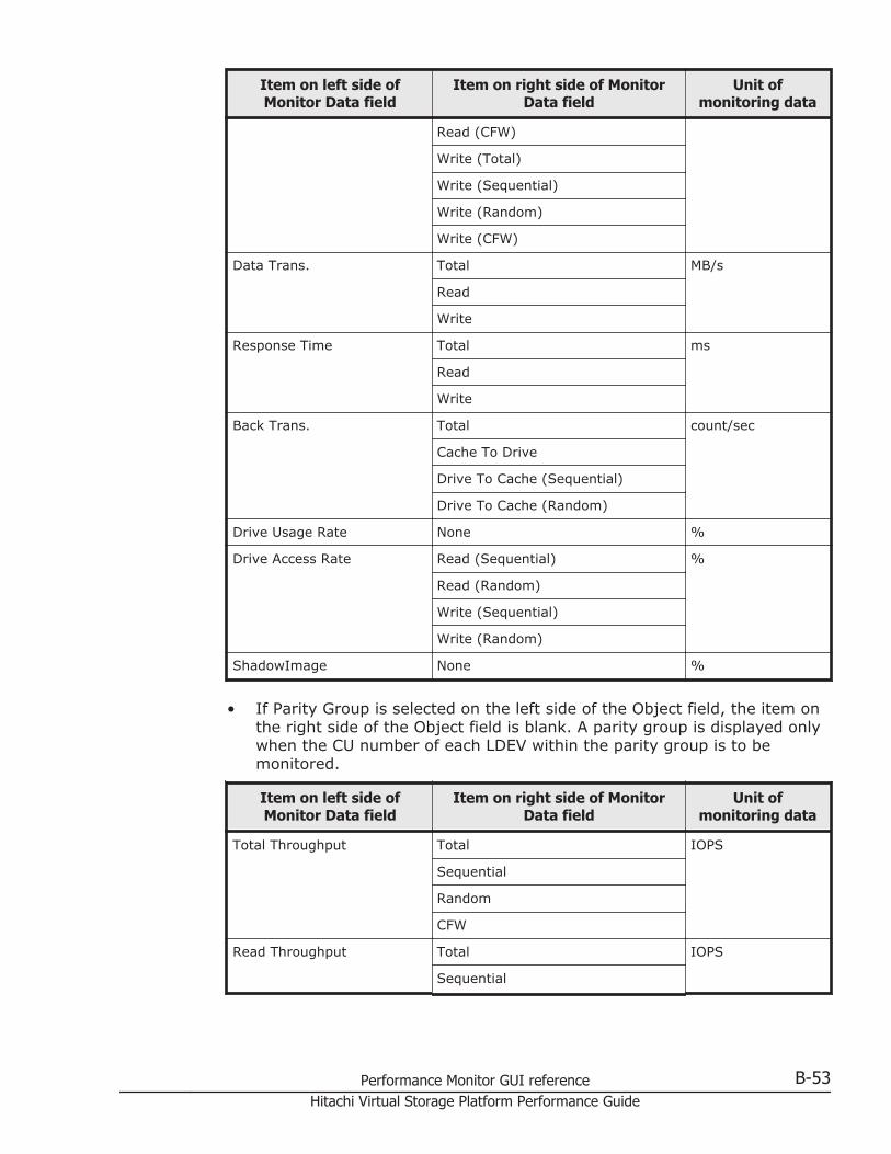
Item on left side ofMonitor Data field
Item on right side of MonitorData field
Unit ofmonitoring data
Read (CFW)
Write (Total)
Write (Sequential)
Write (Random)
Write (CFW)
Data Trans. Total MB/s
Read
Write
Response Time Total ms
Read
Write
Back Trans. Total count/sec
Cache To Drive
Drive To Cache (Sequential)
Drive To Cache (Random)
Drive Usage Rate None %
Drive Access Rate Read (Sequential) %
Read (Random)
Write (Sequential)
Write (Random)
ShadowImage None %
• If Parity Group is selected on the left side of the Object field, the item onthe right side of the Object field is blank. A parity group is displayed onlywhen the CU number of each LDEV within the parity group is to bemonitored.
Item on left side ofMonitor Data field
Item on right side of MonitorData field
Unit ofmonitoring data
Total Throughput Total IOPS
Sequential
Random
CFW
Read Throughput Total IOPS
Sequential
Performance Monitor GUI reference B-53Hitachi Virtual Storage Platform Performance Guide
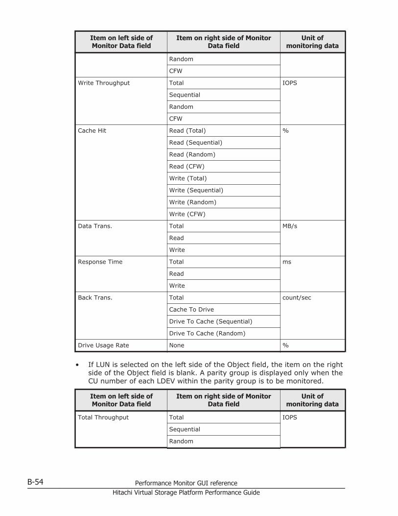
Item on left side ofMonitor Data field
Item on right side of MonitorData field
Unit ofmonitoring data
Random
CFW
Write Throughput Total IOPS
Sequential
Random
CFW
Cache Hit Read (Total) %
Read (Sequential)
Read (Random)
Read (CFW)
Write (Total)
Write (Sequential)
Write (Random)
Write (CFW)
Data Trans. Total MB/s
Read
Write
Response Time Total ms
Read
Write
Back Trans. Total count/sec
Cache To Drive
Drive To Cache (Sequential)
Drive To Cache (Random)
Drive Usage Rate None %
• If LUN is selected on the left side of the Object field, the item on the rightside of the Object field is blank. A parity group is displayed only when theCU number of each LDEV within the parity group is to be monitored.
Item on left side ofMonitor Data field
Item on right side of MonitorData field
Unit ofmonitoring data
Total Throughput Total IOPS
Sequential
Random
B-54 Performance Monitor GUI referenceHitachi Virtual Storage Platform Performance Guide
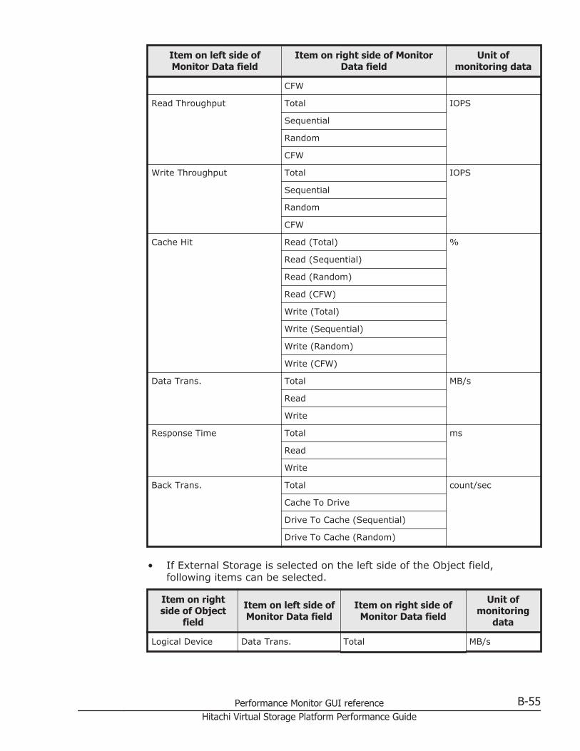
Item on left side ofMonitor Data field
Item on right side of MonitorData field
Unit ofmonitoring data
CFW
Read Throughput Total IOPS
Sequential
Random
CFW
Write Throughput Total IOPS
Sequential
Random
CFW
Cache Hit Read (Total) %
Read (Sequential)
Read (Random)
Read (CFW)
Write (Total)
Write (Sequential)
Write (Random)
Write (CFW)
Data Trans. Total MB/s
Read
Write
Response Time Total ms
Read
Write
Back Trans. Total count/sec
Cache To Drive
Drive To Cache (Sequential)
Drive To Cache (Random)
• If External Storage is selected on the left side of the Object field,following items can be selected.
Item on rightside of Object
field
Item on left side ofMonitor Data field
Item on right side ofMonitor Data field
Unit ofmonitoring
data
Logical Device Data Trans. Total MB/s
Performance Monitor GUI reference B-55Hitachi Virtual Storage Platform Performance Guide
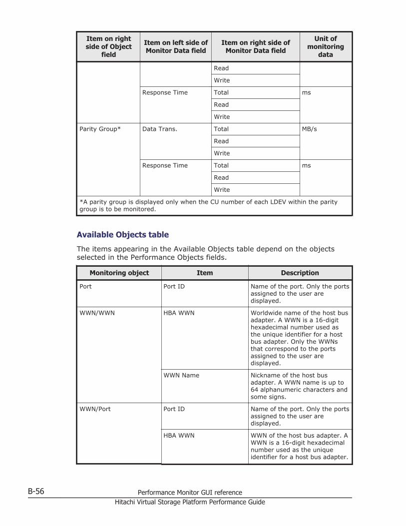
Item on rightside of Object
field
Item on left side ofMonitor Data field
Item on right side ofMonitor Data field
Unit ofmonitoring
data
Read
Write
Response Time Total ms
Read
Write
Parity Group* Data Trans. Total MB/s
Read
Write
Response Time Total ms
Read
Write
*A parity group is displayed only when the CU number of each LDEV within the paritygroup is to be monitored.
Available Objects table
The items appearing in the Available Objects table depend on the objectsselected in the Performance Objects fields.
Monitoring object Item Description
Port Port ID Name of the port. Only the portsassigned to the user aredisplayed.
WWN/WWN HBA WWN Worldwide name of the host busadapter. A WWN is a 16-digithexadecimal number used asthe unique identifier for a hostbus adapter. Only the WWNsthat correspond to the portsassigned to the user aredisplayed.
WWN Name Nickname of the host busadapter. A WWN name is up to64 alphanumeric characters andsome signs.
WWN/Port Port ID Name of the port. Only the portsassigned to the user aredisplayed.
HBA WWN WWN of the host bus adapter. AWWN is a 16-digit hexadecimalnumber used as the uniqueidentifier for a host bus adapter.
B-56 Performance Monitor GUI referenceHitachi Virtual Storage Platform Performance Guide
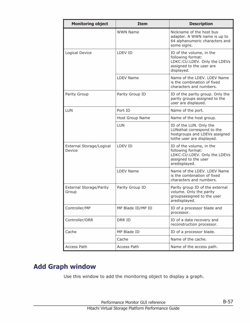
Monitoring object Item Description
WWN Name Nickname of the host busadapter. A WWN name is up to64 alphanumeric characters andsome signs.
Logical Device LDEV ID ID of the volume, in thefollowing format:LDKC:CU:LDEV. Only the LDEVsassigned to the user aredisplayed.
LDEV Name Name of the LDEV. LDEV Nameis the combination of fixedcharacters and numbers.
Parity Group Parity Group ID ID of the parity group. Only theparity groups assigned to theuser are displayed.
LUN Port ID Name of the port.
Host Group Name Name of the host group.
LUN ID of the LUN. Only theLUNsthat correspond to thehostgroups and LDEVs assignedtothe user are displayed.
External Storage/LogicalDevice
LDEV ID ID of the volume, in thefollowing format:LDKC:CU:LDEV. Only the LDEVsassigned to the useraredisplayed.
LDEV Name Name of the LDEV. LDEV Nameis the combination of fixedcharacters and numbers.
External Storage/ParityGroup
Parity Group ID Parity group ID of the externalvolume. Only the paritygroupsassigned to the useraredisplayed.
Controller/MP MP Blade ID/MP ID ID of a processor blade andprocessor.
Controller/DRR DRR ID ID of a data recovery andreconstruction processor.
Cache MP Blade ID ID of a processor blade.
Cache Name of the cache.
Access Path Access Path Name of the access path.
Add Graph windowUse this window to add the monitoring object to display a graph.
Performance Monitor GUI reference B-57Hitachi Virtual Storage Platform Performance Guide
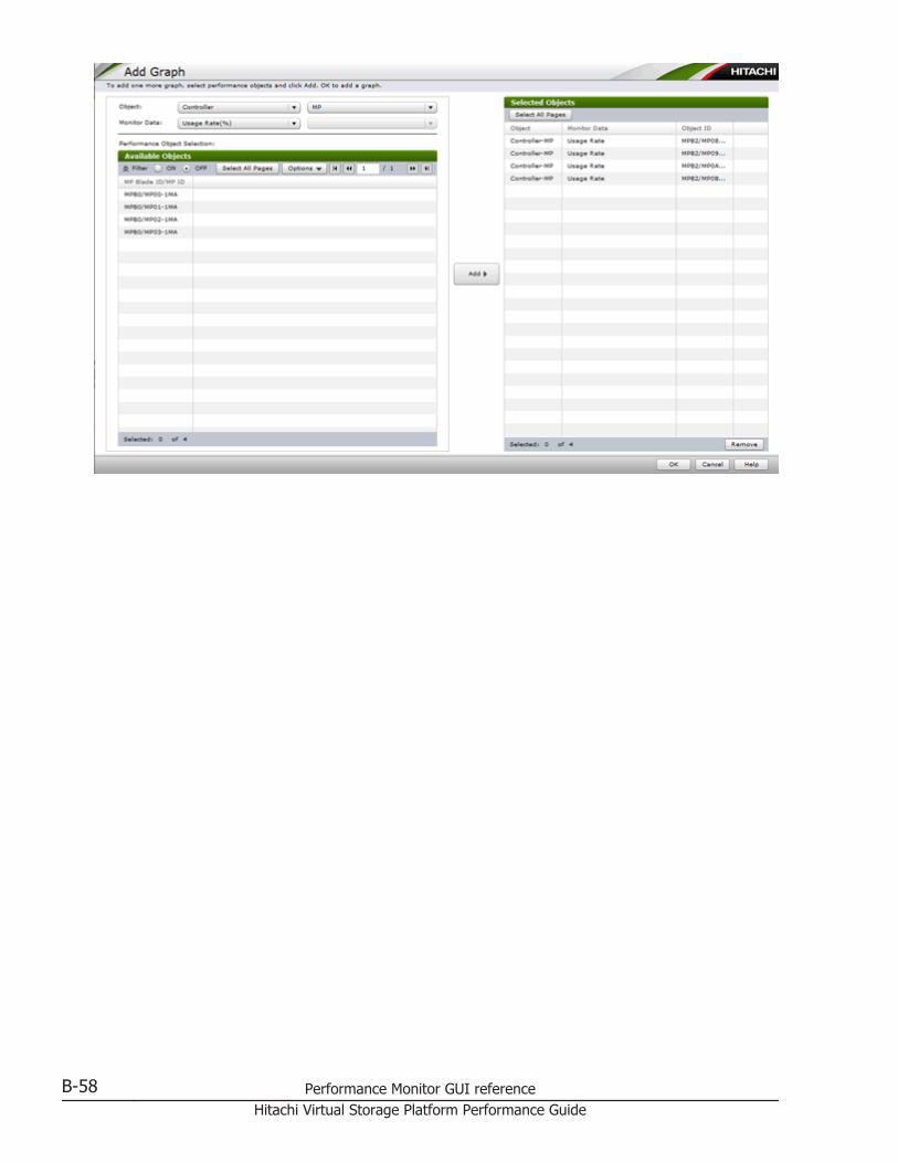
B-58 Performance Monitor GUI referenceHitachi Virtual Storage Platform Performance Guide
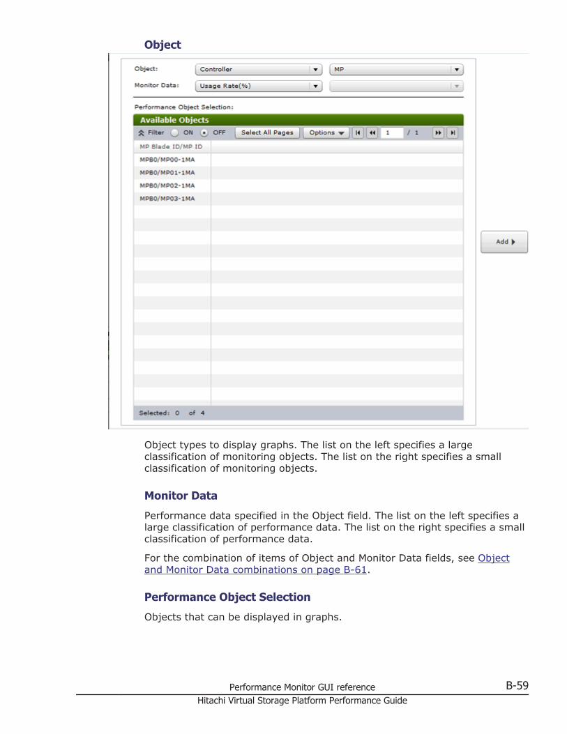
Object
Object types to display graphs. The list on the left specifies a largeclassification of monitoring objects. The list on the right specifies a smallclassification of monitoring objects.
Monitor Data
Performance data specified in the Object field. The list on the left specifies alarge classification of performance data. The list on the right specifies a smallclassification of performance data.
For the combination of items of Object and Monitor Data fields, see Objectand Monitor Data combinations on page B-61.
Performance Object Selection
Objects that can be displayed in graphs.
Performance Monitor GUI reference B-59Hitachi Virtual Storage Platform Performance Guide
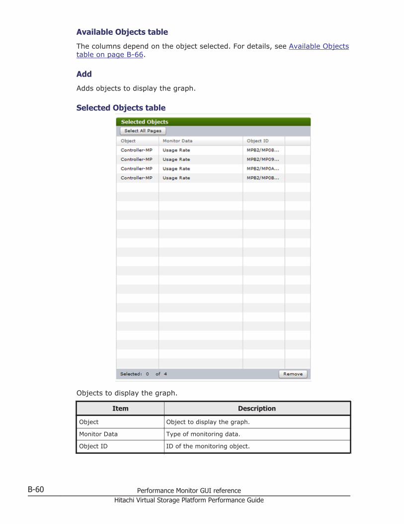
Available Objects table
The columns depend on the object selected. For details, see Available Objectstable on page B-66.
Add
Adds objects to display the graph.
Selected Objects table
Objects to display the graph.
Item Description
Object Object to display the graph.
Monitor Data Type of monitoring data.
Object ID ID of the monitoring object.
B-60 Performance Monitor GUI referenceHitachi Virtual Storage Platform Performance Guide
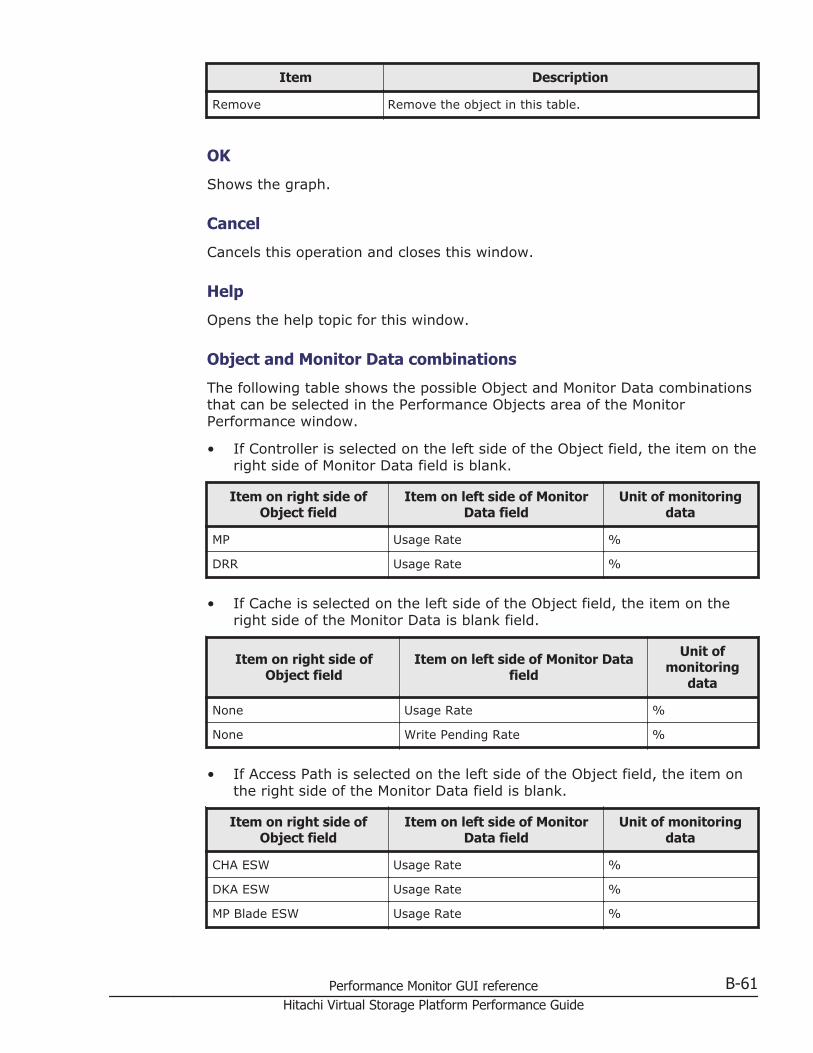
Item Description
Remove Remove the object in this table.
OK
Shows the graph.
Cancel
Cancels this operation and closes this window.
Help
Opens the help topic for this window.
Object and Monitor Data combinations
The following table shows the possible Object and Monitor Data combinationsthat can be selected in the Performance Objects area of the MonitorPerformance window.
• If Controller is selected on the left side of the Object field, the item on theright side of Monitor Data field is blank.
Item on right side ofObject field
Item on left side of MonitorData field
Unit of monitoringdata
MP Usage Rate %
DRR Usage Rate %
• If Cache is selected on the left side of the Object field, the item on theright side of the Monitor Data is blank field.
Item on right side ofObject field
Item on left side of Monitor Datafield
Unit ofmonitoring
data
None Usage Rate %
None Write Pending Rate %
• If Access Path is selected on the left side of the Object field, the item onthe right side of the Monitor Data field is blank.
Item on right side ofObject field
Item on left side of MonitorData field
Unit of monitoringdata
CHA ESW Usage Rate %
DKA ESW Usage Rate %
MP Blade ESW Usage Rate %
Performance Monitor GUI reference B-61Hitachi Virtual Storage Platform Performance Guide
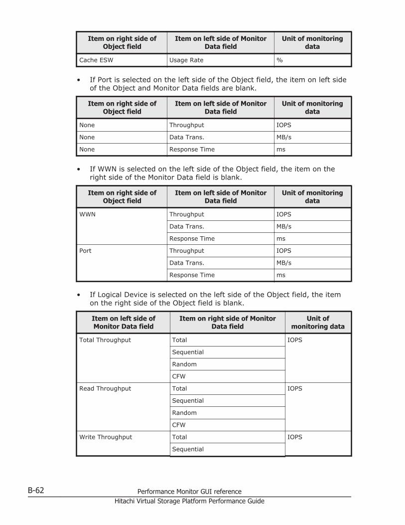
Item on right side ofObject field
Item on left side of MonitorData field
Unit of monitoringdata
Cache ESW Usage Rate %
• If Port is selected on the left side of the Object field, the item on left sideof the Object and Monitor Data fields are blank.
Item on right side ofObject field
Item on left side of MonitorData field
Unit of monitoringdata
None Throughput IOPS
None Data Trans. MB/s
None Response Time ms
• If WWN is selected on the left side of the Object field, the item on theright side of the Monitor Data field is blank.
Item on right side ofObject field
Item on left side of MonitorData field
Unit of monitoringdata
WWN Throughput IOPS
Data Trans. MB/s
Response Time ms
Port Throughput IOPS
Data Trans. MB/s
Response Time ms
• If Logical Device is selected on the left side of the Object field, the itemon the right side of the Object field is blank.
Item on left side ofMonitor Data field
Item on right side of MonitorData field
Unit ofmonitoring data
Total Throughput Total IOPS
Sequential
Random
CFW
Read Throughput Total IOPS
Sequential
Random
CFW
Write Throughput Total IOPS
Sequential
B-62 Performance Monitor GUI referenceHitachi Virtual Storage Platform Performance Guide
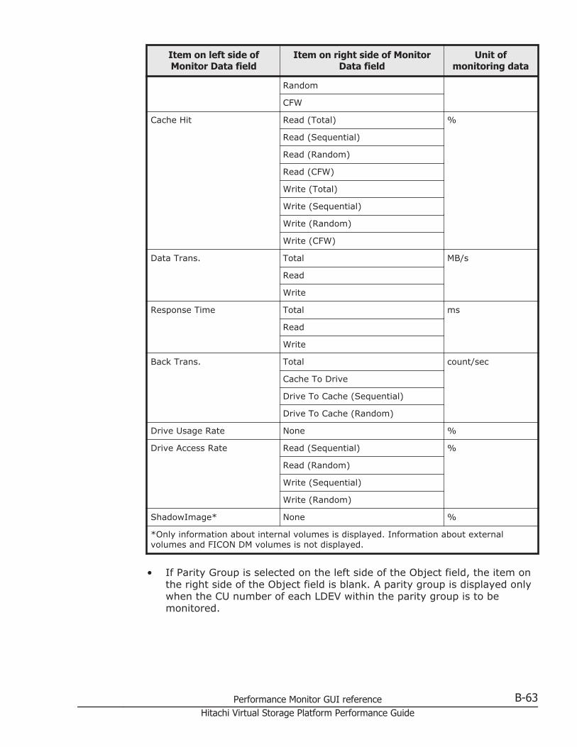
Item on left side ofMonitor Data field
Item on right side of MonitorData field
Unit ofmonitoring data
Random
CFW
Cache Hit Read (Total) %
Read (Sequential)
Read (Random)
Read (CFW)
Write (Total)
Write (Sequential)
Write (Random)
Write (CFW)
Data Trans. Total MB/s
Read
Write
Response Time Total ms
Read
Write
Back Trans. Total count/sec
Cache To Drive
Drive To Cache (Sequential)
Drive To Cache (Random)
Drive Usage Rate None %
Drive Access Rate Read (Sequential) %
Read (Random)
Write (Sequential)
Write (Random)
ShadowImage* None %
*Only information about internal volumes is displayed. Information about externalvolumes and FICON DM volumes is not displayed.
• If Parity Group is selected on the left side of the Object field, the item onthe right side of the Object field is blank. A parity group is displayed onlywhen the CU number of each LDEV within the parity group is to bemonitored.
Performance Monitor GUI reference B-63Hitachi Virtual Storage Platform Performance Guide
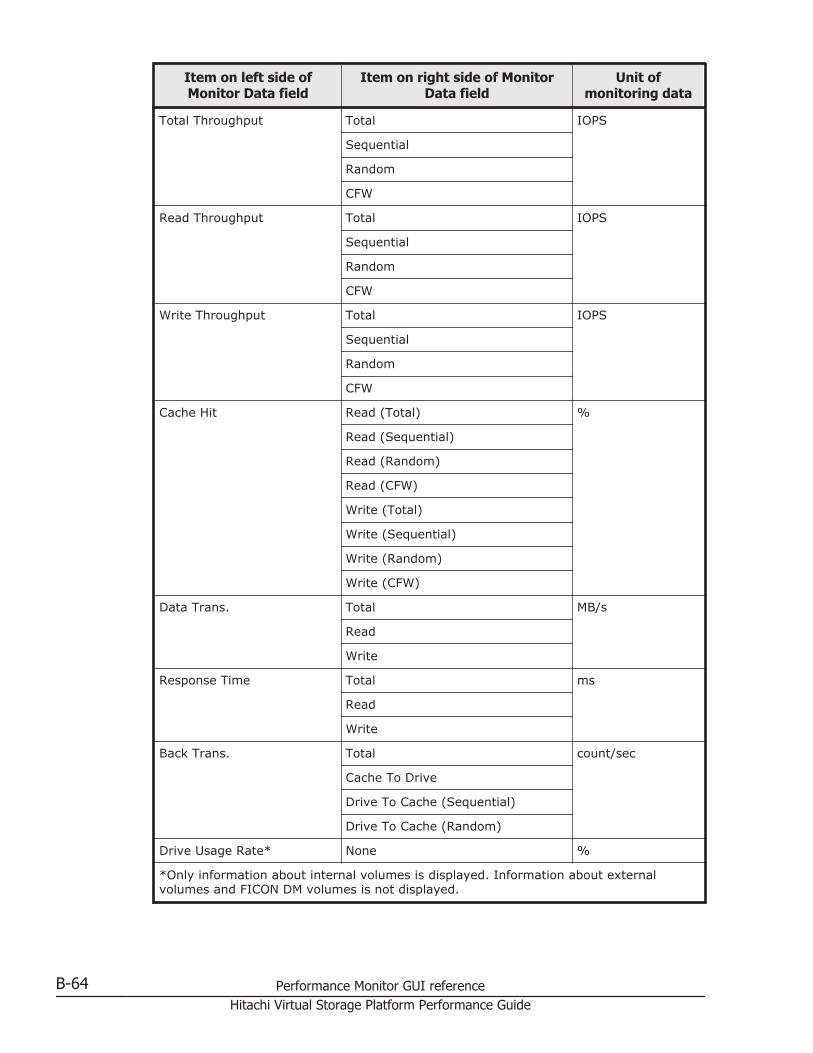
Item on left side ofMonitor Data field
Item on right side of MonitorData field
Unit ofmonitoring data
Total Throughput Total IOPS
Sequential
Random
CFW
Read Throughput Total IOPS
Sequential
Random
CFW
Write Throughput Total IOPS
Sequential
Random
CFW
Cache Hit Read (Total) %
Read (Sequential)
Read (Random)
Read (CFW)
Write (Total)
Write (Sequential)
Write (Random)
Write (CFW)
Data Trans. Total MB/s
Read
Write
Response Time Total ms
Read
Write
Back Trans. Total count/sec
Cache To Drive
Drive To Cache (Sequential)
Drive To Cache (Random)
Drive Usage Rate* None %
*Only information about internal volumes is displayed. Information about externalvolumes and FICON DM volumes is not displayed.
B-64 Performance Monitor GUI referenceHitachi Virtual Storage Platform Performance Guide
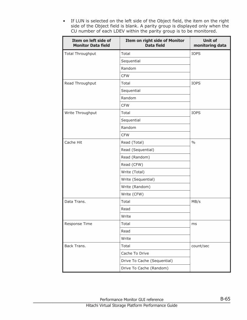
• If LUN is selected on the left side of the Object field, the item on the rightside of the Object field is blank. A parity group is displayed only when theCU number of each LDEV within the parity group is to be monitored.
Item on left side ofMonitor Data field
Item on right side of MonitorData field
Unit ofmonitoring data
Total Throughput Total IOPS
Sequential
Random
CFW
Read Throughput Total IOPS
Sequential
Random
CFW
Write Throughput Total IOPS
Sequential
Random
CFW
Cache Hit Read (Total) %
Read (Sequential)
Read (Random)
Read (CFW)
Write (Total)
Write (Sequential)
Write (Random)
Write (CFW)
Data Trans. Total MB/s
Read
Write
Response Time Total ms
Read
Write
Back Trans. Total count/sec
Cache To Drive
Drive To Cache (Sequential)
Drive To Cache (Random)
Performance Monitor GUI reference B-65Hitachi Virtual Storage Platform Performance Guide
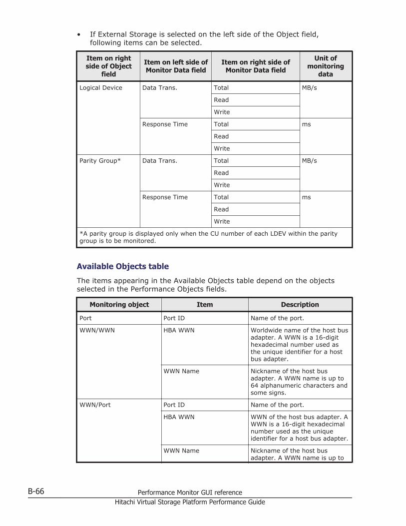
• If External Storage is selected on the left side of the Object field,following items can be selected.
Item on rightside of Object
field
Item on left side ofMonitor Data field
Item on right side ofMonitor Data field
Unit ofmonitoring
data
Logical Device Data Trans. Total MB/s
Read
Write
Response Time Total ms
Read
Write
Parity Group* Data Trans. Total MB/s
Read
Write
Response Time Total ms
Read
Write
*A parity group is displayed only when the CU number of each LDEV within the paritygroup is to be monitored.
Available Objects table
The items appearing in the Available Objects table depend on the objectsselected in the Performance Objects fields.
Monitoring object Item Description
Port Port ID Name of the port.
WWN/WWN HBA WWN Worldwide name of the host busadapter. A WWN is a 16-digithexadecimal number used asthe unique identifier for a hostbus adapter.
WWN Name Nickname of the host busadapter. A WWN name is up to64 alphanumeric characters andsome signs.
WWN/Port Port ID Name of the port.
HBA WWN WWN of the host bus adapter. AWWN is a 16-digit hexadecimalnumber used as the uniqueidentifier for a host bus adapter.
WWN Name Nickname of the host busadapter. A WWN name is up to
B-66 Performance Monitor GUI referenceHitachi Virtual Storage Platform Performance Guide
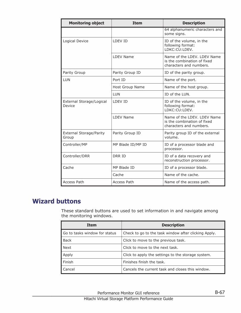
Monitoring object Item Description
64 alphanumeric characters andsome signs.
Logical Device LDEV ID ID of the volume, in thefollowing format:LDKC:CU:LDEV.
LDEV Name Name of the LDEV. LDEV Nameis the combination of fixedcharacters and numbers.
Parity Group Parity Group ID ID of the parity group.
LUN Port ID Name of the port.
Host Group Name Name of the host group.
LUN ID of the LUN.
External Storage/LogicalDevice
LDEV ID ID of the volume, in thefollowing format:LDKC:CU:LDEV.
LDEV Name Name of the LDEV. LDEV Nameis the combination of fixedcharacters and numbers.
External Storage/ParityGroup
Parity Group ID Parity group ID of the externalvolume.
Controller/MP MP Blade ID/MP ID ID of a processor blade andprocessor.
Controller/DRR DRR ID ID of a data recovery andreconstruction processor.
Cache MP Blade ID ID of a processor blade.
Cache Name of the cache.
Access Path Access Path Name of the access path.
Wizard buttonsThese standard buttons are used to set information in and navigate amongthe monitoring windows.
Item Description
Go to tasks window for status Check to go to the task window after clicking Apply.
Back Click to move to the previous task.
Next Click to move to the next task.
Apply Click to apply the settings to the storage system.
Finish Finishes finish the task.
Cancel Cancels the current task and closes this window.
Performance Monitor GUI reference B-67Hitachi Virtual Storage Platform Performance Guide
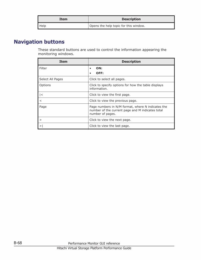
Item Description
Help Opens the help topic for this window.
Navigation buttonsThese standard buttons are used to control the information appearing themonitoring windows.
Item Description
Filter • ON:• OFF:
Select All Pages Click to select all pages.
Options Click to specify options for how the table displaysinformation.
|< Click to view the first page.
< Click to view the previous page.
Page Page numbers in N/M format, where N indicates thenumber of the current page and M indicates totalnumber of pages.
> Click to view the next page.
>| Click to view the last page.
B-68 Performance Monitor GUI referenceHitachi Virtual Storage Platform Performance Guide

CServer Priority Manager GUI reference
This topic provides reference information about the Server Priority ManagerGUI.
□ Server Priority Manager window
□ Port tab of the Server Priority Manager main window
□ WWN tab of the Server Priority Manager main window
Server Priority Manager GUI reference C-1Hitachi Virtual Storage Platform Performance Guide
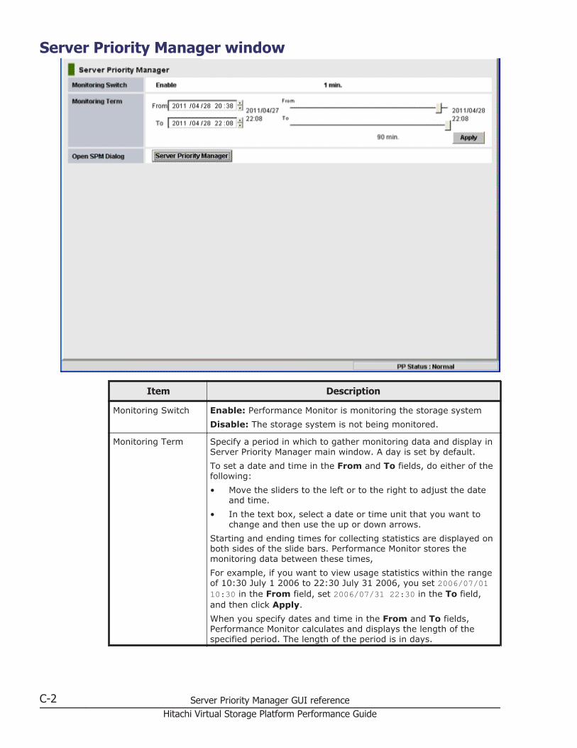
Server Priority Manager window
Item Description
Monitoring Switch Enable: Performance Monitor is monitoring the storage systemDisable: The storage system is not being monitored.
Monitoring Term Specify a period in which to gather monitoring data and display inServer Priority Manager main window. A day is set by default.To set a date and time in the From and To fields, do either of thefollowing:• Move the sliders to the left or to the right to adjust the date
and time.• In the text box, select a date or time unit that you want to
change and then use the up or down arrows.Starting and ending times for collecting statistics are displayed onboth sides of the slide bars. Performance Monitor stores themonitoring data between these times,For example, if you want to view usage statistics within the rangeof 10:30 July 1 2006 to 22:30 July 31 2006, you set 2006/07/0110:30 in the From field, set 2006/07/31 22:30 in the To field,and then click Apply.When you specify dates and time in the From and To fields,Performance Monitor calculates and displays the length of thespecified period. The length of the period is in days.
C-2 Server Priority Manager GUI referenceHitachi Virtual Storage Platform Performance Guide
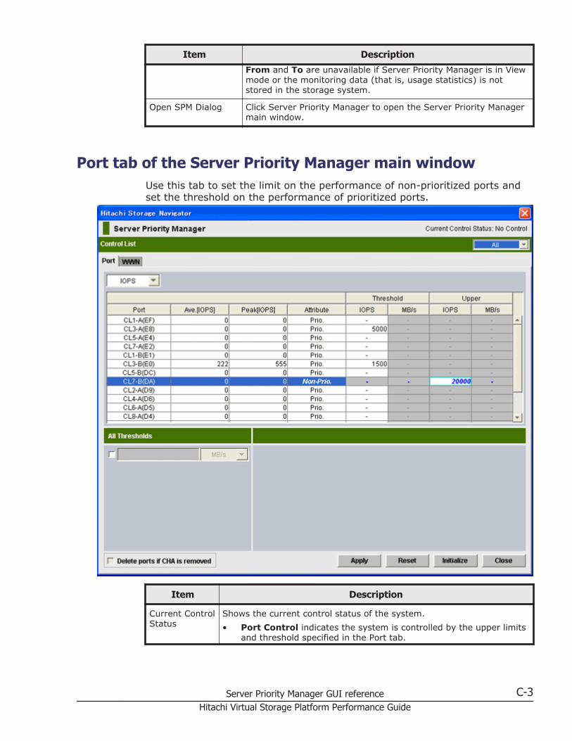
Item Description
From and To are unavailable if Server Priority Manager is in Viewmode or the monitoring data (that is, usage statistics) is notstored in the storage system.
Open SPM Dialog Click Server Priority Manager to open the Server Priority Managermain window.
Port tab of the Server Priority Manager main windowUse this tab to set the limit on the performance of non-prioritized ports andset the threshold on the performance of prioritized ports.
Item Description
Current ControlStatus
Shows the current control status of the system.• Port Control indicates the system is controlled by the upper limits
and threshold specified in the Port tab.
Server Priority Manager GUI reference C-3Hitachi Virtual Storage Platform Performance Guide
Item Description
• WWN Control indicates the system is controlled by the upperlimits and threshold specified in the WWN tab.
• No Control indicates the system performance is not controlled byServer Priority Manager.
Tip: If WWN Control is displayed when the Port tab is active, clickApply to switch control so that Port Control is displayed.Tip: To return the control status to No Control, specify Prio. forattributes of all the ports and then click Apply.
Control List Allows you to narrow ports appearing in the list:• If All is selected, all the ports appear in the list.• If Prioritize is selected, only the prioritized ports appear in the list.• If Non-Prioritize is selected, only the non-prioritized ports appear
in the list.If you change settings of a port, that port remains in the list regardlessof the selection in the list.
Statistic typelist
Allows you to change the type of performance statistics to be displayedin the list.• If IOPS (I/Os per second) is selected, the list displays I/O rates for
ports. The I/O rate indicates the number of I/Os per second.• If MB/s (megabytes per second) is selected, the list displays the
transfer rates for ports. The transfer rate indicates the size of datatransferred via a port in one second.
Ports table A list of ports, including the I/O rate or the transfer rate for each port.You can specify the port attributes, and the threshold and upper limit ofthe port traffic.The measurement unit for the values in the list can be specified by thedrop-down list above this table. The port traffic (I/O rate and transferrate) is monitored by Performance Monitor. To specify the monitoringperiod, use the Monitoring Term area of Performance Monitor.The table contains these columns:• Port indicates ports on the storage system.• Ave.[IOPS] indicates the average I/O rate or the average transfer
rate for the specified period.• Peak[IOPS] indicates the peak I/O rate or the peak transfer rate
of the ports for the specified period. This value means the top ofthe Max. line in the detailed port-traffic graph drawn in the MonitorPerformance window. For details, see Chapter 7, Working withgraphs on page 7-1.
• Attribute indicates the priority of each port. Prio indicates aprioritized port. Non-Prio indicates a non-prioritized port.
• Use the Threshold columns to specify the threshold for the I/Orate and the transfer rate for each prioritized port. Either the IOPSor MB/s column in the list is activated depending on the selectionfrom the list above.Use the IOPS column to specify the threshold for I/O rates. Usethe MB/s column to specify the threshold for transfer rates.To specify a threshold, double-click a cell to display the cursor inthe cell. If you specify a value in either the IOPS or MB/s column,
C-4 Server Priority Manager GUI referenceHitachi Virtual Storage Platform Performance Guide
Item Description
the other column is unavailable. You can specify thresholds for I/Orates and transfer rates all together for different prioritized ports.Even if you use the type of rate for the threshold different fromthat used for the upper limit values, the threshold control can workfor all the ports.
• Use the Upper columns to specify the upper limit on the I/O rateand the transfer rate for each non-prioritized port. Either the IOPSor MB/s column in the list is activated depending on the selectionfrom the list above.Use the IOPS column to specify the upper limit for I/O rates. Usethe MB/s column to specify the upper limit for transfer rates.To specify an upper limit, double-click a cell to display the cursor inthe cell. If you specify a value in either of the IOPS or MB/scolumn, the other column is unavailable. You can specify upperlimit values for I/O rates and transfer rates all together for differentnon-prioritized ports.
All Thresholds If you select this check box and enter a threshold value in the text box,the threshold value is applied to the entire storage system.To specify the threshold for the I/O rate, select IOPS from the list onthe right of the text box. To specify the threshold for the transfer rate,select MB/s from the list. For example, if you specify 128 IOPS in AllThresholds, the upper limits on non-prioritized ports are disabledwhen the sum of I/O rates for all the prioritized ports is below 128IOPS.Even if you use the different type of rate (IOPS or MB/s) for thethreshold as that used for the upper limit values, the threshold controlcan work for all the ports.
Delete ports ifCHA isremoved
If you check this check box, Server Priority Manager deletes, from SVP,the setting information of Server Priority Manager on ports in channeladapters that have been removed.When a channel adapter is removed, the port and its settings areremoved from the Server Priority Manager main window automatically,but they remain in SVP. This may cause the old setting for ServerPriority Manager to be applied to a different channel adapter than theone newly-installed on the same location.The Delete ports if CHA is removed check box is available only whenthe following Server Priority Manager settings on ports in a removedchannel adapter remains on SVP:• The setting of prioritized ports or non-prioritized ports.• The setting of prioritized WWNs or non-prioritized WWNs.
Apply Applies the settings in this window to the storage system.
Reset Restores the last applied settings in the window. When you click thisbutton, all the changes displayed with the blue text in the window arecanceled.
Initialize Changes the settings in this window as explained below, and thenapplies the resulting settings to the storage system:• All the ports become prioritized ports.• The threshold value for all the ports becomes 0 (zero).• The window will display a hyphen (-) instead of 0 (zero).
Server Priority Manager GUI reference C-5Hitachi Virtual Storage Platform Performance Guide
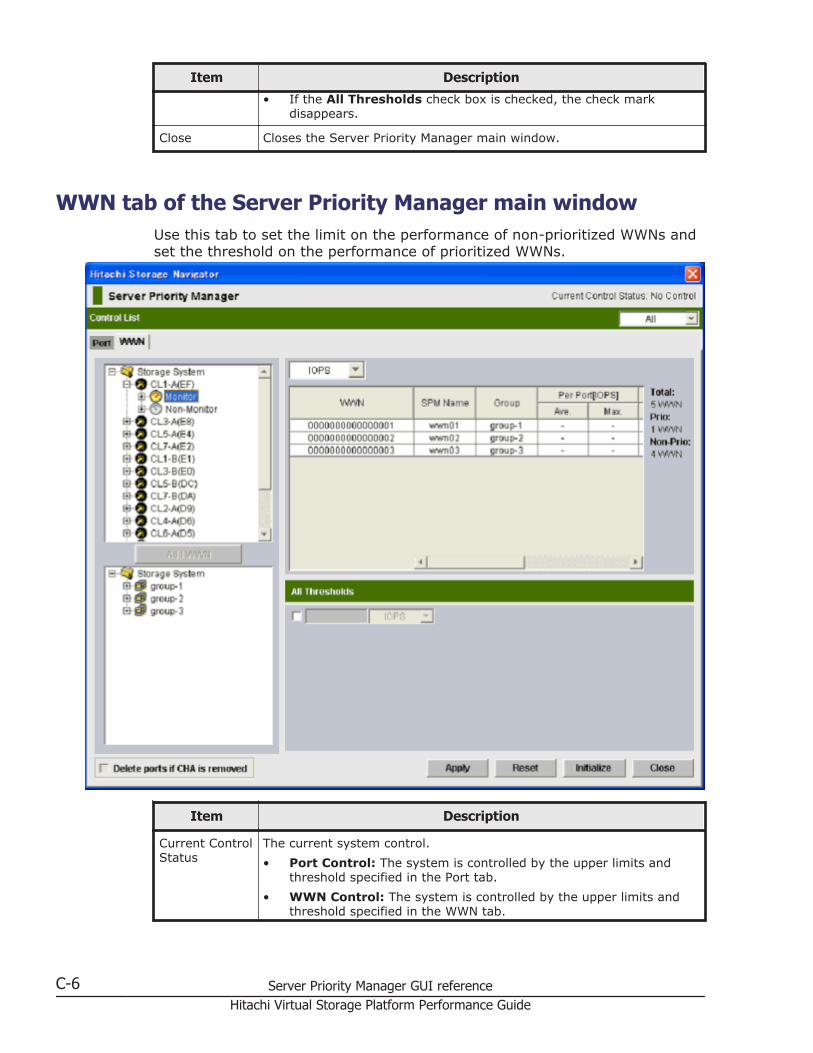
Item Description
• If the All Thresholds check box is checked, the check markdisappears.
Close Closes the Server Priority Manager main window.
WWN tab of the Server Priority Manager main windowUse this tab to set the limit on the performance of non-prioritized WWNs andset the threshold on the performance of prioritized WWNs.
Item Description
Current ControlStatus
The current system control.• Port Control: The system is controlled by the upper limits and
threshold specified in the Port tab.• WWN Control: The system is controlled by the upper limits and
threshold specified in the WWN tab.
C-6 Server Priority Manager GUI referenceHitachi Virtual Storage Platform Performance Guide
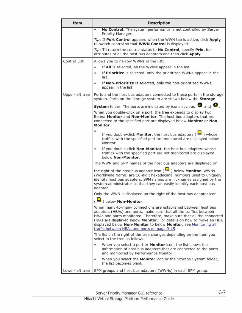
Item Description
• No Control: The system performance is not controlled by ServerPriority Manager.
Tip: If Port Control appears when the WWN tab is active, click Applyto switch control so that WWN Control is displayed.Tip: To return the control status to No Control, specify Prio. forattributes of all the host bus adapters and then click Apply.
Control List Allows you to narrow WWNs in the list:• If All is selected, all the WWNs appear in the list.• If Prioritize is selected, only the prioritized WWNs appear in the
list.• If Non-Prioritize is selected, only the non-prioritized WWNs
appear in the list.
Upper-left tree Ports and the host bus adapters connected to these ports in the storagesystem. Ports on the storage system are shown below the Storage
System folder. The ports are indicated by icons such as and .When you double-click on a port, the tree expands to display twoitems: Monitor and Non-Monitor. The host bus adapters that areconnected to the specified port are displayed below Monitor or Non-Monitor.•
If you double-click Monitor, the host bus adapters ( ) whosetraffics with the specified port are monitored are displayed belowMonitor.
• If you double-click Non-Monitor, the host bus adapters whosetraffics with the specified port are not monitored are displayedbelow Non-Monitor.
The WWN and SPM names of the host bus adapters are displayed on
the right of the host bus adapter icon ( ) below Monitor. WWNs(Worldwide Name) are 16-digit hexadecimal numbers used to uniquelyidentify host bus adapters. SPM names are nicknames assigned by thesystem administrator so that they can easily identify each host busadapter.Only the WWN is displayed on the right of the host bus adapter icon
( ) below Non-Monitor.When many-to-many connections are established between host busadapters (HBAs) and ports, make sure that all the traffics betweenHBAs and ports monitored. Therefore, make sure that all the connectedHBAs are displayed below Monitor. For details on how to move an HBAdisplayed below Non-Monitor to below Monitor, see Monitoring alltraffic between HBAs and ports on page 9-15.The list on the right of the tree changes depending on the item youselect in the tree as follows.• When you select a port or Monitor icon, the list shows the
information of host bus adapters that are connected to the portsand monitored by Performance Monitor.
• When you select the Monitor icon or the Storage System folder,the list becomes blank.
Lower-left tree SPM groups and host bus adapters (WWNs) in each SPM group:
Server Priority Manager GUI reference C-7Hitachi Virtual Storage Platform Performance Guide
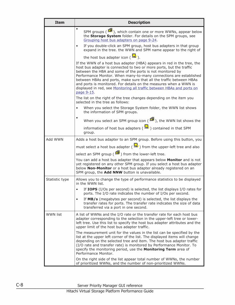
Item Description
•SPM groups ( ), which contain one or more WWNs, appear belowthe Storage System folder. For details on the SPM groups, seeGrouping host bus adapters on page 9-24.
• If you double-click an SPM group, host bus adapters in that groupexpand in the tree. the WWN and SPM name appear to the right of
the host bus adapter icon ( ).If the WWN of a host bus adapter (HBA) appears in red in the tree, thehost bus adapter is connected to two or more ports, but the trafficbetween the HBA and some of the ports is not monitored byPerformance Monitor. When many-to-many connections are establishedbetween HBAs and ports, make sure that all the traffic between HBAsand ports is monitored. For details on the measures when a WWN isdisplayed in red, see Monitoring all traffic between HBAs and ports onpage 9-15.The list on the right of the tree changes depending on the item youselected in the tree as follows:• When you select the Storage System folder, the WWN list shows
the information of SPM groups.•
When you select an SPM group icon ( ), the WWN list shows the
information of host bus adapters ( ) contained in that SPMgroup.
Add WWN Adds a host bus adapter to an SPM group. Before using this button, you
must select a host bus adapter ( ) from the upper-left tree and also
select an SPM group ( ) from the lower-left tree.You can add a host bus adapter that appears below Monitor and is notyet registered on any other SPM group. If you select a host bus adapterbelow Non-Monitor or a host bus adapter already registered on anSPM group, the Add NNW button is unavailable.
Statistic type Allows you to change the type of performance statistics to be displayedin the WWN list.• If IOPS (I/Os per second) is selected, the list displays I/O rates for
ports. The I/O rate indicates the number of I/Os per second.• If MB/s (megabytes per second) is selected, the list displays the
transfer rates for ports. The transfer rate indicates the size of datatransferred via a port in one second.
WWN list A list of WWNs and the I/O rate or the transfer rate for each host busadapter corresponding to the selection in the upper-left tree or lower-left tree. Use this list to specify the host bus adapter attributes and theupper limit of the host bus adapter traffic.The measurement unit for the values in the list can be specified by thelist at the upper left corner of the list. The displayed items will changedepending on the selected tree and item. The host bus adapter traffic(I/O rate and transfer rate) is monitored by Performance Monitor. Tospecify the monitoring period, use the Monitoring Term area ofPerformance Monitor.On the right side of the list appear total number of WWNs, the numberof prioritized WWNs, and the number of non-prioritized WWNs.
C-8 Server Priority Manager GUI referenceHitachi Virtual Storage Platform Performance Guide
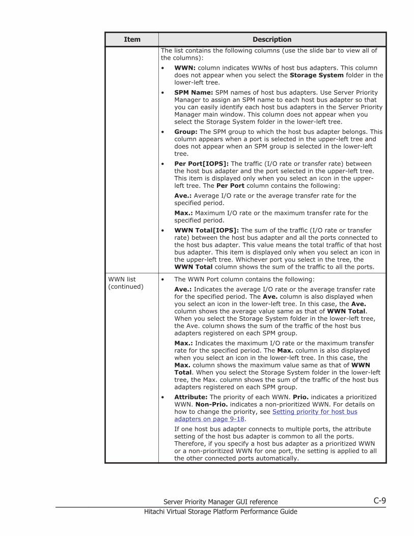
Item Description
The list contains the following columns (use the slide bar to view all ofthe columns):• WWN: column indicates WWNs of host bus adapters. This column
does not appear when you select the Storage System folder in thelower-left tree.
• SPM Name: SPM names of host bus adapters. Use Server PriorityManager to assign an SPM name to each host bus adapter so thatyou can easily identify each host bus adapters in the Server PriorityManager main window. This column does not appear when youselect the Storage System folder in the lower-left tree.
• Group: The SPM group to which the host bus adapter belongs. Thiscolumn appears when a port is selected in the upper-left tree anddoes not appear when an SPM group is selected in the lower-lefttree.
• Per Port[IOPS]: The traffic (I/O rate or transfer rate) betweenthe host bus adapter and the port selected in the upper-left tree.This item is displayed only when you select an icon in the upper-left tree. The Per Port column contains the following:Ave.: Average I/O rate or the average transfer rate for thespecified period.Max.: Maximum I/O rate or the maximum transfer rate for thespecified period.
• WWN Total[IOPS]: The sum of the traffic (I/O rate or transferrate) between the host bus adapter and all the ports connected tothe host bus adapter. This value means the total traffic of that hostbus adapter. This item is displayed only when you select an icon inthe upper-left tree. Whichever port you select in the tree, theWWN Total column shows the sum of the traffic to all the ports.
WWN list(continued)
• The WWN Port column contains the following:Ave.: Indicates the average I/O rate or the average transfer ratefor the specified period. The Ave. column is also displayed whenyou select an icon in the lower-left tree. In this case, the Ave.column shows the average value same as that of WWN Total.When you select the Storage System folder in the lower-left tree,the Ave. column shows the sum of the traffic of the host busadapters registered on each SPM group.Max.: Indicates the maximum I/O rate or the maximum transferrate for the specified period. The Max. column is also displayedwhen you select an icon in the lower-left tree. In this case, theMax. column shows the maximum value same as that of WWNTotal. When you select the Storage System folder in the lower-lefttree, the Max. column shows the sum of the traffic of the host busadapters registered on each SPM group.
• Attribute: The priority of each WWN. Prio. indicates a prioritizedWWN. Non-Prio. indicates a non-prioritized WWN. For details onhow to change the priority, see Setting priority for host busadapters on page 9-18.If one host bus adapter connects to multiple ports, the attributesetting of the host bus adapter is common to all the ports.Therefore, if you specify a host bus adapter as a prioritized WWNor a non-prioritized WWN for one port, the setting is applied to allthe other connected ports automatically.
Server Priority Manager GUI reference C-9Hitachi Virtual Storage Platform Performance Guide
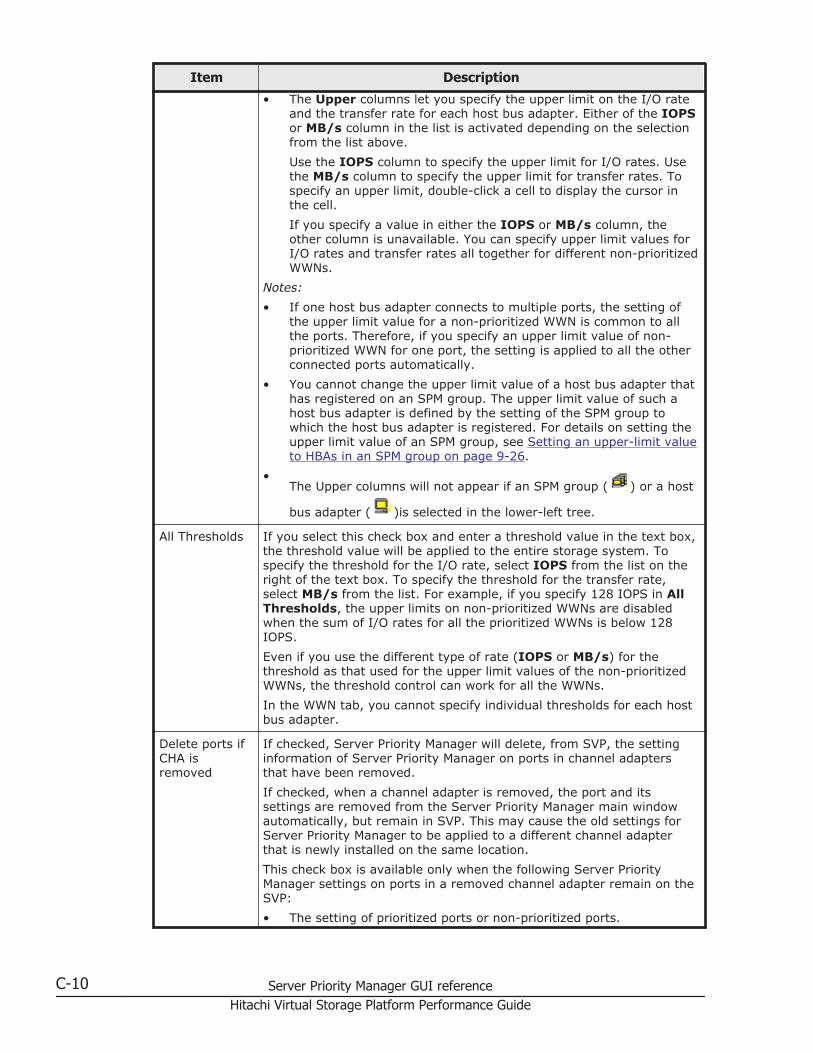
Item Description
• The Upper columns let you specify the upper limit on the I/O rateand the transfer rate for each host bus adapter. Either of the IOPSor MB/s column in the list is activated depending on the selectionfrom the list above.Use the IOPS column to specify the upper limit for I/O rates. Usethe MB/s column to specify the upper limit for transfer rates. Tospecify an upper limit, double-click a cell to display the cursor inthe cell.If you specify a value in either the IOPS or MB/s column, theother column is unavailable. You can specify upper limit values forI/O rates and transfer rates all together for different non-prioritizedWWNs.
Notes:• If one host bus adapter connects to multiple ports, the setting of
the upper limit value for a non-prioritized WWN is common to allthe ports. Therefore, if you specify an upper limit value of non-prioritized WWN for one port, the setting is applied to all the otherconnected ports automatically.
• You cannot change the upper limit value of a host bus adapter thathas registered on an SPM group. The upper limit value of such ahost bus adapter is defined by the setting of the SPM group towhich the host bus adapter is registered. For details on setting theupper limit value of an SPM group, see Setting an upper-limit valueto HBAs in an SPM group on page 9-26.
•The Upper columns will not appear if an SPM group ( ) or a host
bus adapter ( )is selected in the lower-left tree.
All Thresholds If you select this check box and enter a threshold value in the text box,the threshold value will be applied to the entire storage system. Tospecify the threshold for the I/O rate, select IOPS from the list on theright of the text box. To specify the threshold for the transfer rate,select MB/s from the list. For example, if you specify 128 IOPS in AllThresholds, the upper limits on non-prioritized WWNs are disabledwhen the sum of I/O rates for all the prioritized WWNs is below 128IOPS.Even if you use the different type of rate (IOPS or MB/s) for thethreshold as that used for the upper limit values of the non-prioritizedWWNs, the threshold control can work for all the WWNs.In the WWN tab, you cannot specify individual thresholds for each hostbus adapter.
Delete ports ifCHA isremoved
If checked, Server Priority Manager will delete, from SVP, the settinginformation of Server Priority Manager on ports in channel adaptersthat have been removed.If checked, when a channel adapter is removed, the port and itssettings are removed from the Server Priority Manager main windowautomatically, but remain in SVP. This may cause the old settings forServer Priority Manager to be applied to a different channel adapterthat is newly installed on the same location.This check box is available only when the following Server PriorityManager settings on ports in a removed channel adapter remain on theSVP:• The setting of prioritized ports or non-prioritized ports.
C-10 Server Priority Manager GUI referenceHitachi Virtual Storage Platform Performance Guide
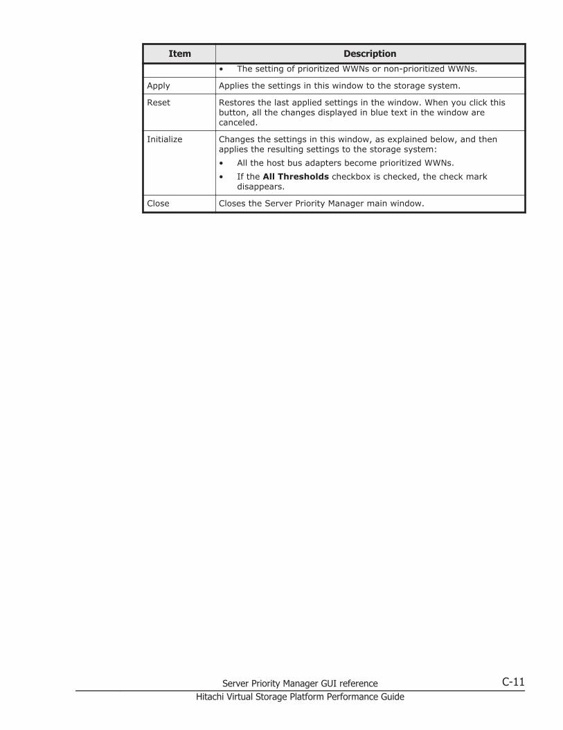
Item Description
• The setting of prioritized WWNs or non-prioritized WWNs.
Apply Applies the settings in this window to the storage system.
Reset Restores the last applied settings in the window. When you click thisbutton, all the changes displayed in blue text in the window arecanceled.
Initialize Changes the settings in this window, as explained below, and thenapplies the resulting settings to the storage system:• All the host bus adapters become prioritized WWNs.• If the All Thresholds checkbox is checked, the check mark
disappears.
Close Closes the Server Priority Manager main window.
Server Priority Manager GUI reference C-11Hitachi Virtual Storage Platform Performance Guide

C-12 Server Priority Manager GUI referenceHitachi Virtual Storage Platform Performance Guide
DVirtual Partition Manager GUI reference
This topic describes the windows that comprise the Virtual Partition ManagerGUI.
□ Partition Definition tab (Storage System selected)
□ Partition Definition tab, Cache Logical Partition window (all CLPRs)
□ Partition Definition tab, Cache Logical Partition window (one CLPR)
□ Select CU dialog box
Virtual Partition Manager GUI reference D-1Hitachi Virtual Storage Platform Performance Guide
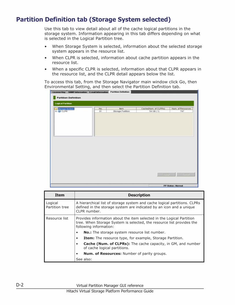
Partition Definition tab (Storage System selected)Use this tab to view detail about all of the cache logical partitions in thestorage system. Information appearing in this tab differs depending on whatis selected in the Logical Partition tree.
• When Storage System is selected, information about the selected storagesystem appears in the resource list.
• When CLPR is selected, information about cache partition appears in theresource list.
• When a specific CLPR is selected, information about that CLPR appears inthe resource list, and the CLPR detail appears below the list.
To access this tab, from the Storage Navigator main window click Go, thenEnvironmental Setting, and then select the Partition Definition tab.
Item Description
LogicalPartition tree
A hierarchical list of storage system and cache logical partitions. CLPRsdefined in the storage system are indicated by an icon and a uniqueCLPR number.
Resource list Provides information about the item selected in the Logical Partitiontree. When Storage System is selected, the resource list provides thefollowing information:• No.: The storage system resource list number.• Item: The resource type, for example, Storage Partition.• Cache (Num. of CLPRs): The cache capacity, in GM, and number
of cache logical partitions.• Num. of Resources: Number of parity groups.See also:
D-2 Virtual Partition Manager GUI referenceHitachi Virtual Storage Platform Performance Guide
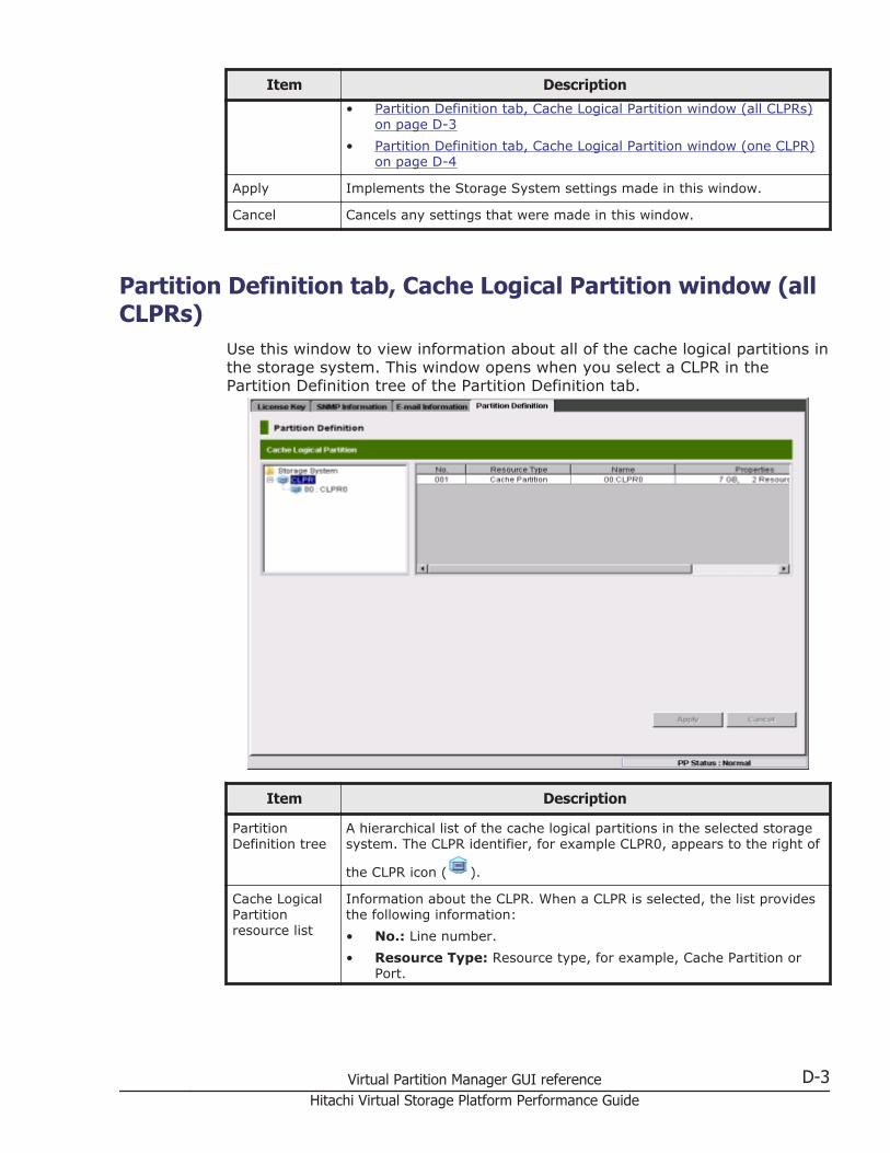
Item Description
• Partition Definition tab, Cache Logical Partition window (all CLPRs)on page D-3
• Partition Definition tab, Cache Logical Partition window (one CLPR)on page D-4
Apply Implements the Storage System settings made in this window.
Cancel Cancels any settings that were made in this window.
Partition Definition tab, Cache Logical Partition window (allCLPRs)
Use this window to view information about all of the cache logical partitions inthe storage system. This window opens when you select a CLPR in thePartition Definition tree of the Partition Definition tab.
Item Description
PartitionDefinition tree
A hierarchical list of the cache logical partitions in the selected storagesystem. The CLPR identifier, for example CLPR0, appears to the right of
the CLPR icon ( ).
Cache LogicalPartitionresource list
Information about the CLPR. When a CLPR is selected, the list providesthe following information:• No.: Line number.• Resource Type: Resource type, for example, Cache Partition or
Port.
Virtual Partition Manager GUI reference D-3Hitachi Virtual Storage Platform Performance Guide
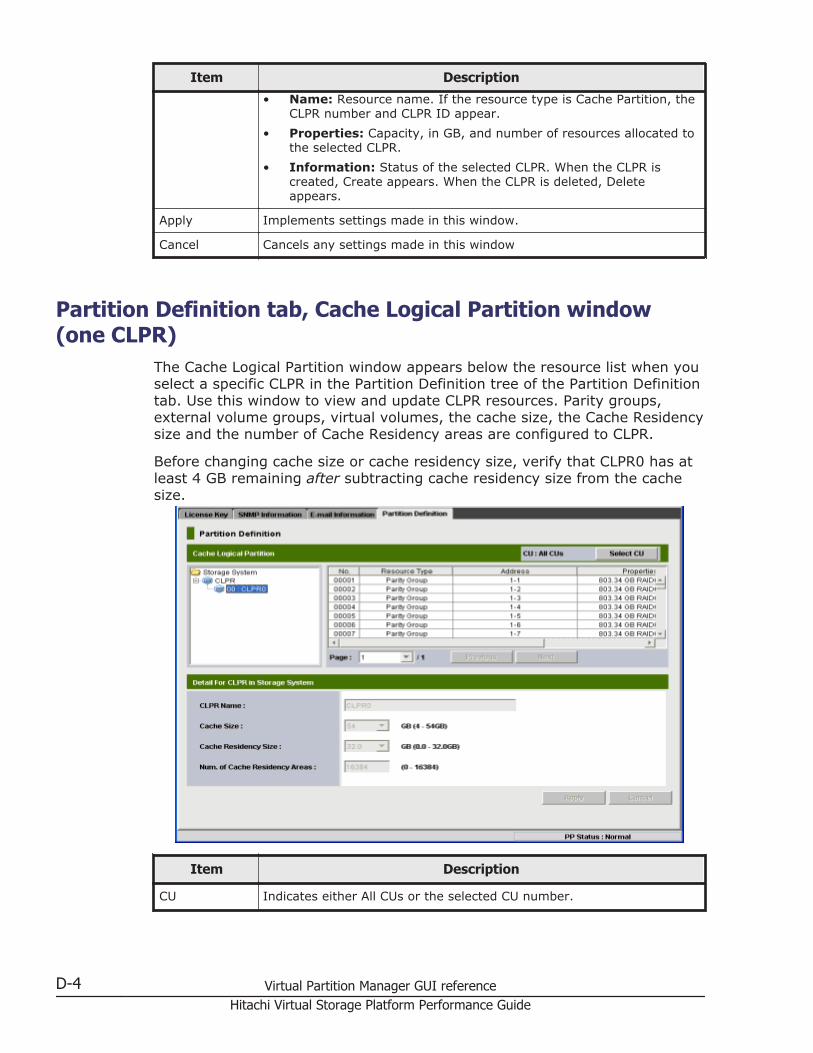
Item Description
• Name: Resource name. If the resource type is Cache Partition, theCLPR number and CLPR ID appear.
• Properties: Capacity, in GB, and number of resources allocated tothe selected CLPR.
• Information: Status of the selected CLPR. When the CLPR iscreated, Create appears. When the CLPR is deleted, Deleteappears.
Apply Implements settings made in this window.
Cancel Cancels any settings made in this window
Partition Definition tab, Cache Logical Partition window(one CLPR)
The Cache Logical Partition window appears below the resource list when youselect a specific CLPR in the Partition Definition tree of the Partition Definitiontab. Use this window to view and update CLPR resources. Parity groups,external volume groups, virtual volumes, the cache size, the Cache Residencysize and the number of Cache Residency areas are configured to CLPR.
Before changing cache size or cache residency size, verify that CLPR0 has atleast 4 GB remaining after subtracting cache residency size from the cachesize.
Item Description
CU Indicates either All CUs or the selected CU number.
D-4 Virtual Partition Manager GUI referenceHitachi Virtual Storage Platform Performance Guide
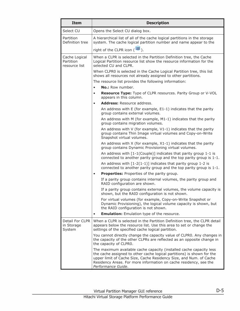
Item Description
Select CU Opens the Select CU dialog box.
PartitionDefinition tree
A hierarchical list of all of the cache logical partitions in the storagesystem. The cache logical partition number and name appear to the
right of the CLPR icon ( ).
Cache LogicalPartitionresource list
When a CLPR is selected in the Partition Definition tree, the CacheLogical Partition resource list show the resource information for theselected CU and CLPR.When CLPR0 is selected in the Cache Logical Partition tree, this listshows all resources not already assigned to other partitions.The resource list provides the following information:• No.: Row number.• Resource Type: Type of CLPR resources. Parity Group or V-VOL
appears in this column.• Address: Resource address.
An address with E (for example, E1-1) indicates that the paritygroup contains external volumes.An address with M (for example, M1-1) indicates that the paritygroup contains migration volumes.An address with V (for example, V1-1) indicates that the paritygroup contains Thin Image virtual volumes and Copy-on-WriteSnapshot virtual volumes.An address with X (for example, X1-1) indicates that the paritygroup contains Dynamic Provisioning virtual volumes.An address with [1-1(Couple)] indicates that parity group 1-1 isconnected to another parity group and the top parity group is 1-1.An address with [1-2(1-1)] indicates that parity group 1-2 isconnected to another parity group and the top parity group is 1-1.
• Properties: Properties of the parity group.If a parity group contains internal volumes, the parity group andRAID configuration are shown.If a parity group contains external volumes, the volume capacity isshown, but the RAID configuration is not shown.For virtual volumes (for example, Copy-on-Write Snapshot orDynamic Provisioning), the logical volume capacity is shown, butthe RAID configuration is not shown.
• Emulation: Emulation type of the resource.
Detail For CLPRin StorageSystem
When a CLPR is selected in the Partition Definition tree, the CLPR detailappears below the resource list. Use this area to set or change thesettings of the specified cache logical partition.You cannot directly change the capacity value of CLPR0. Any changes inthe capacity of the other CLPRs are reflected as an opposite change inthe capacity of CLPR0.The maximum available cache capacity (installed cache capacity lessthe cache assigned to other cache logical partitions) is shown for theupper limit of Cache Size, Cache Residency Size, and Num. of CacheResidency Areas. For more information on cache residency, see thePerformance Guide.
Virtual Partition Manager GUI reference D-5Hitachi Virtual Storage Platform Performance Guide
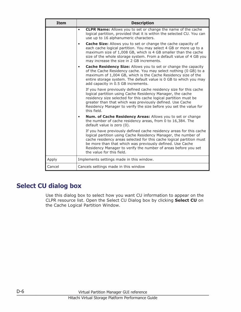
Item Description
• CLPR Name: Allows you to set or change the name of the cachelogical partition, provided that it is within the selected CU. You canuse up to 16 alphanumeric characters.
• Cache Size: Allows you to set or change the cache capacity ofeach cache logical partition. You may select 4 GB or more up to amaximum size of 1,008 GB, which is 4 GB smaller than the cachesize of the whole storage system. From a default value of 4 GB youmay increase the size in 2 GB increments.
• Cache Residency Size: Allows you to set or change the capacityof the Cache Residency cache. You may select nothing (0 GB) to amaximum of 1,004 GB, which is the Cache Residency size of theentire storage system. The default value is 0 GB to which you mayadd capacity in 0.5 GB increments.If you have previously defined cache residency size for this cachelogical partition using Cache Residency Manager, the cacheresidency size selected for this cache logical partition must begreater than that which was previously defined. Use CacheResidency Manager to verify the size before you set the value forthis field.
• Num. of Cache Residency Areas: Allows you to set or changethe number of cache residency areas, from 0 to 16,384. Thedefault value is zero (0).If you have previously defined cache residency areas for this cachelogical partition using Cache Residency Manager, the number ofcache residency areas selected for this cache logical partition mustbe more than that which was previously defined. Use CacheResidency Manager to verify the number of areas before you setthe value for this field.
Apply Implements settings made in this window.
Cancel Cancels settings made in this window
Select CU dialog boxUse this dialog box to select how you want CU information to appear on theCLPR resource list. Open the Select CU Dialog box by clicking Select CU onthe Cache Logical Partition Window.
D-6 Virtual Partition Manager GUI referenceHitachi Virtual Storage Platform Performance Guide
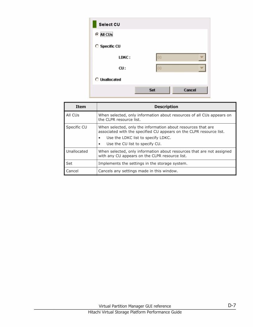
Item Description
All CUs When selected, only information about resources of all CUs appears onthe CLPR resource list.
Specific CU When selected, only the information about resources that areassociated with the specified CU appears on the CLPR resource list.• Use the LDKC list to specify LDKC.• Use the CU list to specify CU.
Unallocated When selected, only information about resources that are not assignedwith any CU appears on the CLPR resource list.
Set Implements the settings in the storage system.
Cancel Cancels any settings made in this window.
Virtual Partition Manager GUI reference D-7Hitachi Virtual Storage Platform Performance Guide

D-8 Virtual Partition Manager GUI referenceHitachi Virtual Storage Platform Performance Guide
ECache Residency Manager GUI
reference
This topic provides reference information about the Cache Residency ManagerGUI.
□ Cache Residency window
□ Multi Set dialog box
□ Multi Release dialog box
Cache Residency Manager GUI reference E-1Hitachi Virtual Storage Platform Performance Guide
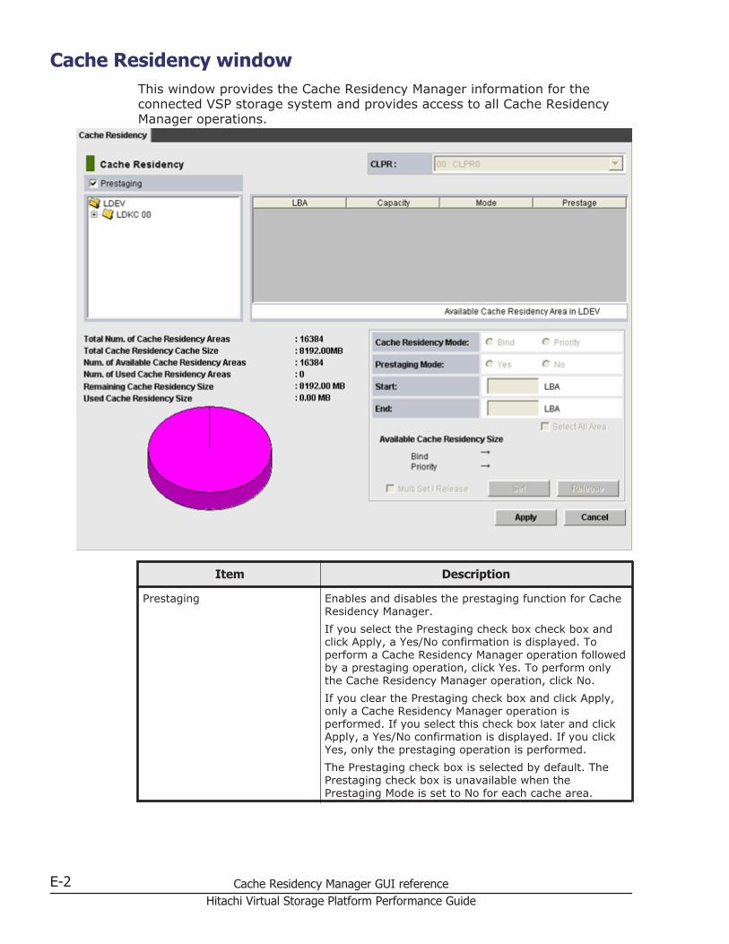
Cache Residency windowThis window provides the Cache Residency Manager information for theconnected VSP storage system and provides access to all Cache ResidencyManager operations.
Item Description
Prestaging Enables and disables the prestaging function for CacheResidency Manager.If you select the Prestaging check box check box andclick Apply, a Yes/No confirmation is displayed. Toperform a Cache Residency Manager operation followedby a prestaging operation, click Yes. To perform onlythe Cache Residency Manager operation, click No.If you clear the Prestaging check box and click Apply,only a Cache Residency Manager operation isperformed. If you select this check box later and clickApply, a Yes/No confirmation is displayed. If you clickYes, only the prestaging operation is performed.The Prestaging check box is selected by default. ThePrestaging check box is unavailable when thePrestaging Mode is set to No for each cache area.
E-2 Cache Residency Manager GUI referenceHitachi Virtual Storage Platform Performance Guide
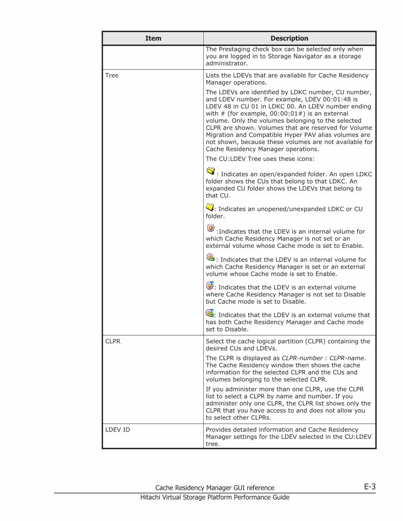
Item Description
The Prestaging check box can be selected only whenyou are logged in to Storage Navigator as a storageadministrator.
Tree Lists the LDEVs that are available for Cache ResidencyManager operations.The LDEVs are identified by LDKC number, CU number,and LDEV number. For example, LDEV 00:01:48 isLDEV 48 in CU 01 in LDKC 00. An LDEV number endingwith # (for example, 00:00:01#) is an externalvolume. Only the volumes belonging to the selectedCLPR are shown. Volumes that are reserved for VolumeMigration and Compatible Hyper PAV alias volumes arenot shown, because these volumes are not available forCache Residency Manager operations.The CU:LDEV Tree uses these icons:
: Indicates an open/expanded folder. An open LDKCfolder shows the CUs that belong to that LDKC. Anexpanded CU folder shows the LDEVs that belong tothat CU.
: Indicates an unopened/unexpanded LDKC or CUfolder.
:Indicates that the LDEV is an internal volume forwhich Cache Residency Manager is not set or anexternal volume whose Cache mode is set to Enable.
: Indicates that the LDEV is an internal volume forwhich Cache Residency Manager is set or an externalvolume whose Cache mode is set to Enable.
: Indicates that the LDEV is an external volumewhere Cache Residency Manager is not set to Disablebut Cache mode is set to Disable.
: Indicates that the LDEV is an external volume thathas both Cache Residency Manager and Cache modeset to Disable.
CLPR Select the cache logical partition (CLPR) containing thedesired CUs and LDEVs.The CLPR is displayed as CLPR-number : CLPR-name.The Cache Residency window then shows the cacheinformation for the selected CLPR and the CUs andvolumes belonging to the selected CLPR.If you administer more than one CLPR, use the CLPRlist to select a CLPR by name and number. If youadminister only one CLPR, the CLPR list shows only theCLPR that you have access to and does not allow youto select other CLPRs.
LDEV ID Provides detailed information and Cache ResidencyManager settings for the LDEV selected in the CU:LDEVtree.
Cache Residency Manager GUI reference E-3Hitachi Virtual Storage Platform Performance Guide
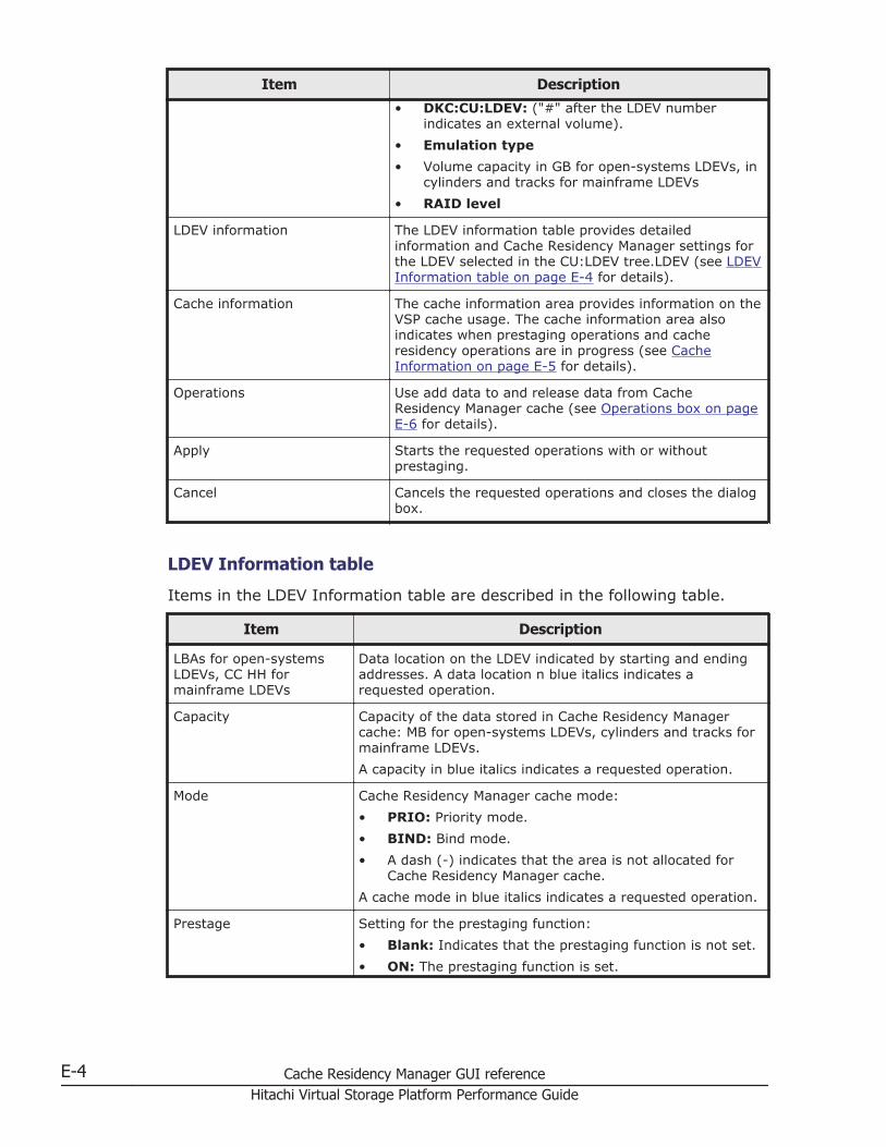
Item Description
• DKC:CU:LDEV: ("#" after the LDEV numberindicates an external volume).
• Emulation type• Volume capacity in GB for open-systems LDEVs, in
cylinders and tracks for mainframe LDEVs• RAID level
LDEV information The LDEV information table provides detailedinformation and Cache Residency Manager settings forthe LDEV selected in the CU:LDEV tree.LDEV (see LDEVInformation table on page E-4 for details).
Cache information The cache information area provides information on theVSP cache usage. The cache information area alsoindicates when prestaging operations and cacheresidency operations are in progress (see CacheInformation on page E-5 for details).
Operations Use add data to and release data from CacheResidency Manager cache (see Operations box on pageE-6 for details).
Apply Starts the requested operations with or withoutprestaging.
Cancel Cancels the requested operations and closes the dialogbox.
LDEV Information table
Items in the LDEV Information table are described in the following table.
Item Description
LBAs for open-systemsLDEVs, CC HH formainframe LDEVs
Data location on the LDEV indicated by starting and endingaddresses. A data location n blue italics indicates arequested operation.
Capacity Capacity of the data stored in Cache Residency Managercache: MB for open-systems LDEVs, cylinders and tracks formainframe LDEVs.A capacity in blue italics indicates a requested operation.
Mode Cache Residency Manager cache mode:• PRIO: Priority mode.• BIND: Bind mode.• A dash (-) indicates that the area is not allocated for
Cache Residency Manager cache.A cache mode in blue italics indicates a requested operation.
Prestage Setting for the prestaging function:• Blank: Indicates that the prestaging function is not set.• ON: The prestaging function is set.
E-4 Cache Residency Manager GUI referenceHitachi Virtual Storage Platform Performance Guide
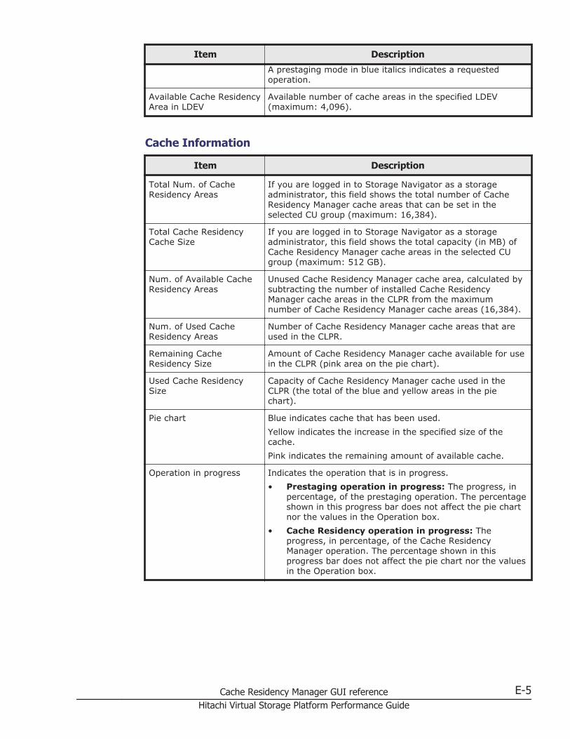
Item Description
A prestaging mode in blue italics indicates a requestedoperation.
Available Cache ResidencyArea in LDEV
Available number of cache areas in the specified LDEV(maximum: 4,096).
Cache Information
Item Description
Total Num. of CacheResidency Areas
If you are logged in to Storage Navigator as a storageadministrator, this field shows the total number of CacheResidency Manager cache areas that can be set in theselected CU group (maximum: 16,384).
Total Cache ResidencyCache Size
If you are logged in to Storage Navigator as a storageadministrator, this field shows the total capacity (in MB) ofCache Residency Manager cache areas in the selected CUgroup (maximum: 512 GB).
Num. of Available CacheResidency Areas
Unused Cache Residency Manager cache area, calculated bysubtracting the number of installed Cache ResidencyManager cache areas in the CLPR from the maximumnumber of Cache Residency Manager cache areas (16,384).
Num. of Used CacheResidency Areas
Number of Cache Residency Manager cache areas that areused in the CLPR.
Remaining CacheResidency Size
Amount of Cache Residency Manager cache available for usein the CLPR (pink area on the pie chart).
Used Cache ResidencySize
Capacity of Cache Residency Manager cache used in theCLPR (the total of the blue and yellow areas in the piechart).
Pie chart Blue indicates cache that has been used.Yellow indicates the increase in the specified size of thecache.Pink indicates the remaining amount of available cache.
Operation in progress Indicates the operation that is in progress.• Prestaging operation in progress: The progress, in
percentage, of the prestaging operation. The percentageshown in this progress bar does not affect the pie chartnor the values in the Operation box.
• Cache Residency operation in progress: Theprogress, in percentage, of the Cache ResidencyManager operation. The percentage shown in thisprogress bar does not affect the pie chart nor the valuesin the Operation box.
Cache Residency Manager GUI reference E-5Hitachi Virtual Storage Platform Performance Guide
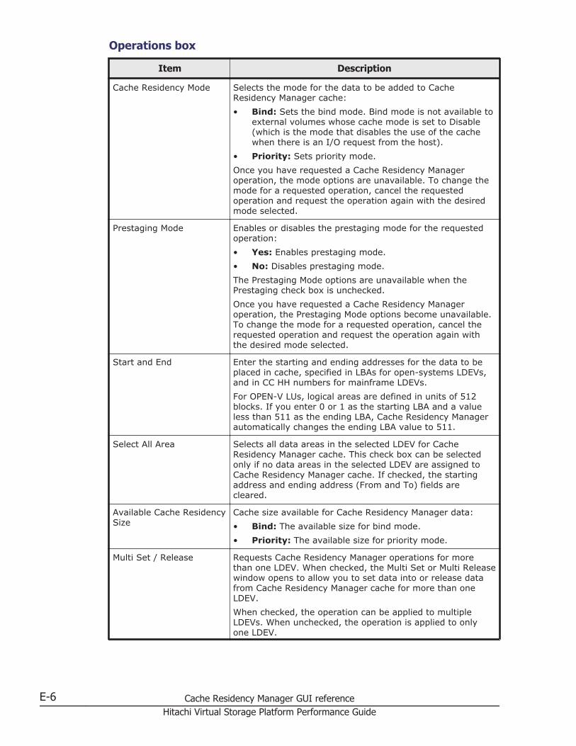
Operations box
Item Description
Cache Residency Mode Selects the mode for the data to be added to CacheResidency Manager cache:• Bind: Sets the bind mode. Bind mode is not available to
external volumes whose cache mode is set to Disable(which is the mode that disables the use of the cachewhen there is an I/O request from the host).
• Priority: Sets priority mode.Once you have requested a Cache Residency Manageroperation, the mode options are unavailable. To change themode for a requested operation, cancel the requestedoperation and request the operation again with the desiredmode selected.
Prestaging Mode Enables or disables the prestaging mode for the requestedoperation:• Yes: Enables prestaging mode.• No: Disables prestaging mode.The Prestaging Mode options are unavailable when thePrestaging check box is unchecked.Once you have requested a Cache Residency Manageroperation, the Prestaging Mode options become unavailable.To change the mode for a requested operation, cancel therequested operation and request the operation again withthe desired mode selected.
Start and End Enter the starting and ending addresses for the data to beplaced in cache, specified in LBAs for open-systems LDEVs,and in CC HH numbers for mainframe LDEVs.For OPEN-V LUs, logical areas are defined in units of 512blocks. If you enter 0 or 1 as the starting LBA and a valueless than 511 as the ending LBA, Cache Residency Managerautomatically changes the ending LBA value to 511.
Select All Area Selects all data areas in the selected LDEV for CacheResidency Manager cache. This check box can be selectedonly if no data areas in the selected LDEV are assigned toCache Residency Manager cache. If checked, the startingaddress and ending address (From and To) fields arecleared.
Available Cache ResidencySize
Cache size available for Cache Residency Manager data:• Bind: The available size for bind mode.• Priority: The available size for priority mode.
Multi Set / Release Requests Cache Residency Manager operations for morethan one LDEV. When checked, the Multi Set or Multi Releasewindow opens to allow you to set data into or release datafrom Cache Residency Manager cache for more than oneLDEV.When checked, the operation can be applied to multipleLDEVs. When unchecked, the operation is applied to onlyone LDEV.
E-6 Cache Residency Manager GUI referenceHitachi Virtual Storage Platform Performance Guide
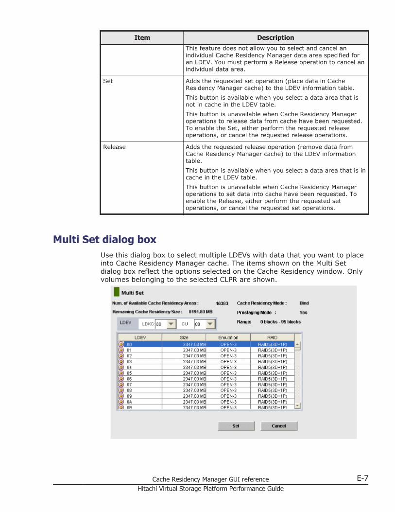
Item Description
This feature does not allow you to select and cancel anindividual Cache Residency Manager data area specified foran LDEV. You must perform a Release operation to cancel anindividual data area.
Set Adds the requested set operation (place data in CacheResidency Manager cache) to the LDEV information table.This button is available when you select a data area that isnot in cache in the LDEV table.This button is unavailable when Cache Residency Manageroperations to release data from cache have been requested.To enable the Set, either perform the requested releaseoperations, or cancel the requested release operations.
Release Adds the requested release operation (remove data fromCache Residency Manager cache) to the LDEV informationtable.This button is available when you select a data area that is incache in the LDEV table.This button is unavailable when Cache Residency Manageroperations to set data into cache have been requested. Toenable the Release, either perform the requested setoperations, or cancel the requested set operations.
Multi Set dialog boxUse this dialog box to select multiple LDEVs with data that you want to placeinto Cache Residency Manager cache. The items shown on the Multi Setdialog box reflect the options selected on the Cache Residency window. Onlyvolumes belonging to the selected CLPR are shown.
Cache Residency Manager GUI reference E-7Hitachi Virtual Storage Platform Performance Guide
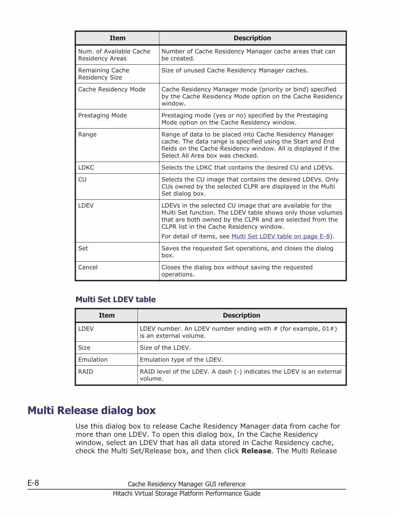
Item Description
Num. of Available CacheResidency Areas
Number of Cache Residency Manager cache areas that canbe created.
Remaining CacheResidency Size
Size of unused Cache Residency Manager caches.
Cache Residency Mode Cache Residency Manager mode (priority or bind) specifiedby the Cache Residency Mode option on the Cache Residencywindow.
Prestaging Mode Prestaging mode (yes or no) specified by the PrestagingMode option on the Cache Residency window.
Range Range of data to be placed into Cache Residency Managercache. The data range is specified using the Start and Endfields on the Cache Residency window. All is displayed if theSelect All Area box was checked.
LDKC Selects the LDKC that contains the desired CU and LDEVs.
CU Selects the CU image that contains the desired LDEVs. OnlyCUs owned by the selected CLPR are displayed in the MultiSet dialog box.
LDEV LDEVs in the selected CU image that are available for theMulti Set function. The LDEV table shows only those volumesthat are both owned by the CLPR and are selected from theCLPR list in the Cache Residency window.For detail of items, see Multi Set LDEV table on page E-8).
Set Saves the requested Set operations, and closes the dialogbox.
Cancel Closes the dialog box without saving the requestedoperations.
Multi Set LDEV table
Item Description
LDEV LDEV number. An LDEV number ending with # (for example, 01#)is an external volume.
Size Size of the LDEV.
Emulation Emulation type of the LDEV.
RAID RAID level of the LDEV. A dash (-) indicates the LDEV is an externalvolume.
Multi Release dialog boxUse this dialog box to release Cache Residency Manager data from cache formore than one LDEV. To open this dialog box, In the Cache Residencywindow, select an LDEV that has all data stored in Cache Residency cache,check the Multi Set/Release box, and then click Release. The Multi Release
E-8 Cache Residency Manager GUI referenceHitachi Virtual Storage Platform Performance Guide
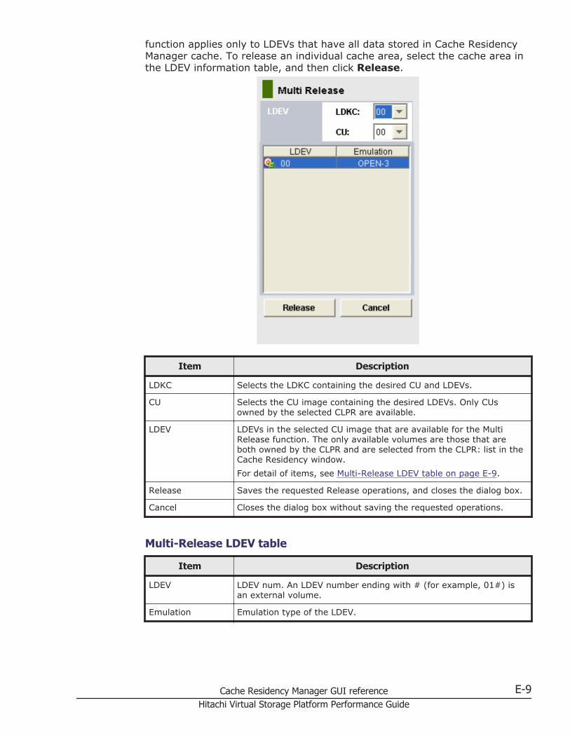
function applies only to LDEVs that have all data stored in Cache ResidencyManager cache. To release an individual cache area, select the cache area inthe LDEV information table, and then click Release.
Item Description
LDKC Selects the LDKC containing the desired CU and LDEVs.
CU Selects the CU image containing the desired LDEVs. Only CUsowned by the selected CLPR are available.
LDEV LDEVs in the selected CU image that are available for the MultiRelease function. The only available volumes are those that areboth owned by the CLPR and are selected from the CLPR: list in theCache Residency window.For detail of items, see Multi-Release LDEV table on page E-9.
Release Saves the requested Release operations, and closes the dialog box.
Cancel Closes the dialog box without saving the requested operations.
Multi-Release LDEV table
Item Description
LDEV LDEV num. An LDEV number ending with # (for example, 01#) isan external volume.
Emulation Emulation type of the LDEV.
Cache Residency Manager GUI reference E-9Hitachi Virtual Storage Platform Performance Guide

E-10 Cache Residency Manager GUI referenceHitachi Virtual Storage Platform Performance Guide
Index
A
access paths and I/O usage rates 7-8Auto LUN
restrictions on manual migration across multipleCLPRs 10-4
B
back-end performance and I/O usage rates 7-15batch file
preparing for use with Export Tool A-8using termination codes in Export Tool A-12
bind mode 1-6and cache size requirements 11-2
Business Copyrestrictions on quick restore operations acrossmultiple CLPRs 10-4
C
cachecapacity recommendations 10-6extents 11-5hit rates and I/O usage rates 7-13managing 12-1memory and I/O usage rates 7-7partitioning 10-1partitioning example 10-2partitions 10-2placing LDEVs into cache 12-7placing specific data into cache 12-5releasing LDEVs from cache 12-10releasing specific data from cache 12-9
rules, restrictions, and guidelines 12-2cache requirements
bind mode 1-7priority mode 1-6
Cache Residency Manager 1-3cache extents 11-5cache requirements 11-1system requirements 11-6
Cache Residency window E-2cache size
estimating 11-1requirements 11-2requirements, calculating for mainframesystems 11-4requirements, calculating for open systems 11-2
CLPRcreating 10-10
CLPRscreating 10-10deleting 10-13migrating resources 10-11
command filepreparing for use with Export Tool A-5
command referenceExport Tool A-14
creating a CLPR 10-10CUs
add to monitoring 4-2remove from monitoring 4-2set up monitoring 4-1
D
data prestaging 1-4
Index-1Hitachi Virtual Storage Platform Performance Guide
data recovery and reconstruction processor andI/O usage rates 7-6data transfer size and I/O usage rates 7-11deleting a CLPR 10-10, 10-13
E
error handlingExport Tool A-13
Export Tool A-1commands A-14error handling A-13file formats A-10log files A-12overview A-2processing time A-11requirements A-3text files A-2uninstalling on a UNIX system A-4uninstalling on a Windows system A-3using A-10
extents 11-5external volumes and cache size requirements11-2
G
graphs 7-1adding new graph panel 8-3changing displayed objects 8-2changing displayed period 8-2configuring 8-1creating and viewing 7-3deleting graph panel 8-3display parameters 8-2objects and data than can be graphed 7-4
H
hard disk drive access rates 7-16hard disk drive and I/O usage rates 7-16host bus adapter 9-2
I
I/O usage ratesaccess paths 7-8back-end performance 7-15
cache hit rates 7-13cache memory 7-7data recovery and reconstruction processor 7-6data transfer size 7-11hard disk drive 7-16hard disk drive access 7-16processor blades 7-6ShadowImage 7-17throughput 7-9write pending 7-7
interleaved parity groups in CLPRs 10-12interoperability
Performance Monitor with other software 2-1I/O rate 9-3
L
LDEVsplacing into cache 12-7releasing from cache 12-10
log filesExport Tool A-12
long range 6-2
M
mainframe systemscalculating cache requirements 11-4
managing resident cache 12-1migrating resources 10-11modes
bind 1-6changing after Cache Residency is registered incache 12-11priority 1-5
Monitor Performance window 2-2monitoring
starting 5-2stopping 5-2
N
non-prioritized port 9-3, 9-11non-prioritized WWN 9-7, 9-19
Index-2Hitachi Virtual Storage Platform Performance Guide
O
open systemscalculating cache requirements 11-2
OPEN-V LUs 12-6
P
partitioning cache 10-1Performance Monitor 1-2performance troubleshooting 13-1placing LDEVs into cache 12-7placing specific data into cache 12-5prestaging data 1-4prioritized port 9-3, 9-11prioritized WWN 9-7, 9-19priority mode 1-5
and cache size requirements 11-2processor blades and I/O usage rates 7-6
R
RAID levels and cache size requirements 11-2releasing LDEVs from cache 12-10releasing specific data from cache 12-9replace microprogram 2-2resident cache
managing 12-1resource usage rates 7-18restrictions
Auto LUN manual migration across multipleCLPRs 10-4Business Copy quick restore operations acrossmultiple CLPRs 10-4ShadowImage quick restore operations acrossmultiple CLPRs 10-4Volume Migration manual migration acrossmultiple CLPRs 10-4
S
ShadowImageI/O usage rates 7-17restrictions on quick restore operations acrossmultiple CLPRs 10-4
short range 6-2SPM group 9-24starting monitoring 5-2
statistics 6-1setting storing period 6-2storage ranges 6-2viewing 6-2
stopping monitoring 5-2
T
throughput and I/O usage rates 7-9top 20 resource usage rates 7-18transfer rate 9-3troubleshooting
Cache Partition 10-13performance 13-1Virtual Partition Manager 10-13
V
virtual cache partitions 10-2Volume Migration
restrictions on manual migration across multipleCLPRs 10-4
W
write pending and I/O usage rates 7-7WWNs
adding to monitoring 3-2, 3-3connecting to ports 3-4editing nickname 3-3removing from monitoring 3-2, 3-4setting up monitoring 3-1viewing 3-2
Index-3Hitachi Virtual Storage Platform Performance Guide

Index-4Hitachi Virtual Storage Platform Performance Guide

Hitachi Virtual Storage Platform Performance Guide
Hitachi Data Systems
Corporate Headquarters2845 Lafayette StreetSanta Clara, California 95050-2639U.S.A.www.hds.com
Regional Contact Information
Americas+1 408 970 [email protected]
Europe, Middle East, and Africa+44 (0)1753 [email protected]
Asia Pacific+852 3189 [email protected]
MK-90RD7020-13